Embed Size (px)
Citation preview
4.2.11 Student Book © 2004 Propane Education & Research Council Page 1
4.2.11Installing Manifold Cylinders or Tanks
When installing manifold DOT cylinders or ASME tanks, it is essential to understand and identify the different components and applications required by safety codes for their installation.
In this module you will learn to:(1) Identify basic NFPA code requirements for manifold container
installations(2) Identify manifold cylinder systems and applications (3) Select components for manifold cylinder systems (4) Identify components for typical vapor service manifold tank
installations with single regulator configuration (5) Identify components for typical vapor service manifold tank
installations with parallel regulator configuration (6) Identify code requirements and components for manifold tanks in
liquid service
4.2.11 Student Book © 2004 Propane Education & Research Council Page 1
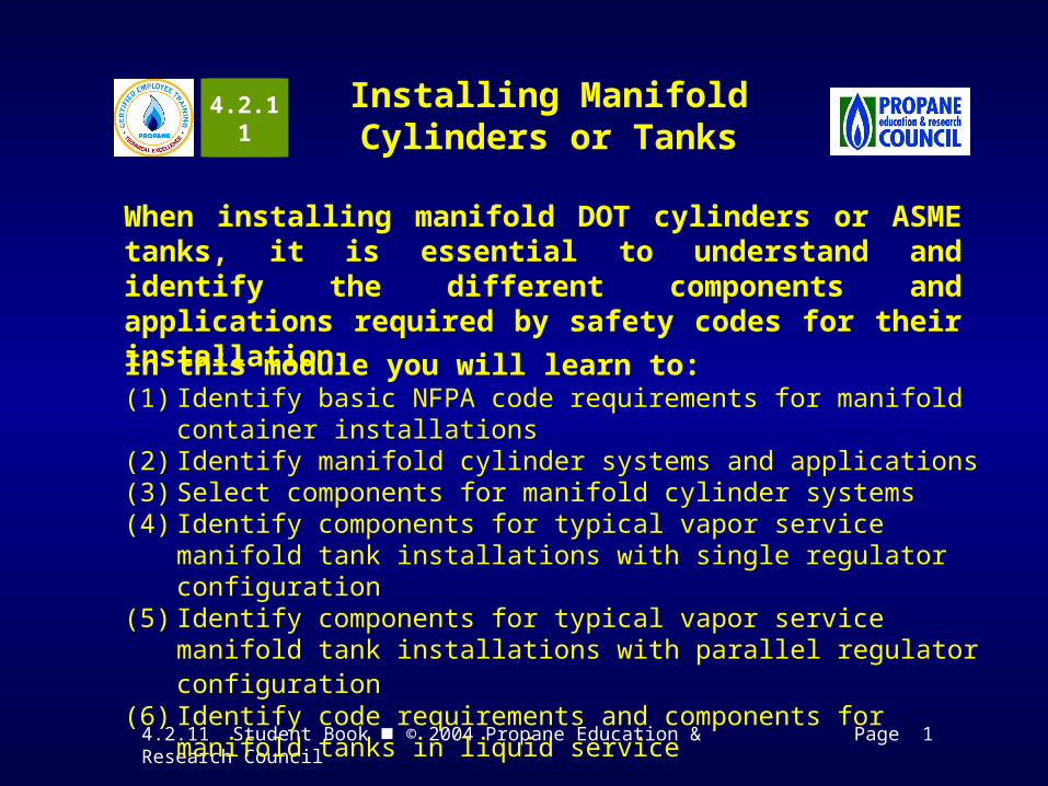
NFPA Code Requirements for Manifold Container Installations
2001 Edition Reference NFPA 58 Requirement
2004 Edition Reference
2.3 Liquid outlets of tanks and cylinders must be equipped with internal excess flow valves.
5.7.7
3.2.6.2 ASME tanks that have liquid interconnections must be installed so that the maximum permitted filling level of each tank is at the same elevation.
6.6.3.2
3.4.10.2(c) An excess flow valve sized for the smaller diameter pipe is required at any reduction in pipe size where liquid piping conveys liquid LP-gas into a building or structure, such as a building or structure housing a vaporizer.
6.17.12.2
4.2.11 Student Book © 2004 Propane Education & Research Council Pages 1& 2
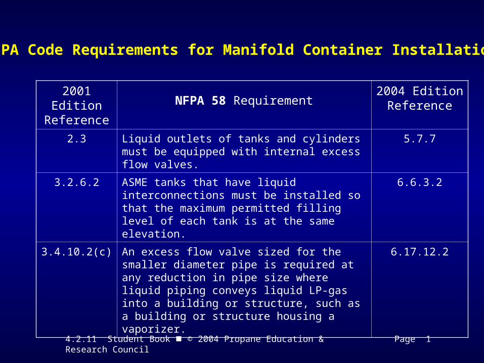
NFPA Code Requirements for Manifold Container Installations
2001 Edition Reference NFPA 58 Requirement
2004 Edition Reference
2.3.3.2 (a)(4) Most propane system installers and jurisdictional authorities interpret 2.3.3.2 (a)(4) as a requirement for excess-flow protection in manifold tank or cylinder installations, where the first-stage regulator is connected to tank service valves using vapor piping longer than the pigtail used in typical single tank installations and where the regulator is installed outside of the tank dome.
5.7.7.1 (F)
3.2.2 Manifold containers must be located in compliance with the minimum separation distances from important buildings, property lines that may be built upon, and other containers as shown in Table 3.2.2.2. Separation distances from container relief valves and building openings must comply with Table 3.2.2.2(d).
6.3
Table 6.3.1
Table 6.3.9
4.2.11 Student Book © 2004 Propane Education & Research Council Page 2
NFPA Code Requirements for Manifold Container Installations
2001 Edition Reference NFPA 58 Requirement
2004 Edition Reference
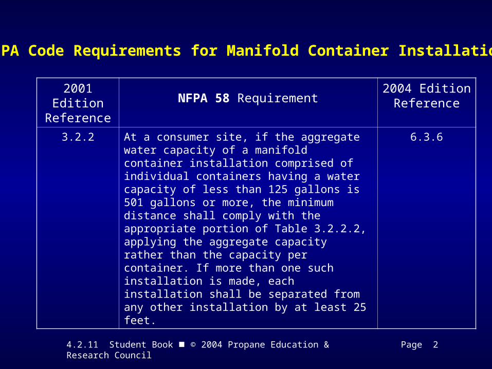
3.2.2 At a consumer site, if the aggregate water capacity of a manifold container installation comprised of individual containers having a water capacity of less than 125 gallons is 501 gallons or more, the minimum distance shall comply with the appropriate portion of Table 3.2.2.2, applying the aggregate capacity rather than the capacity per container. If more than one such installation is made, each installation shall be separated from any other installation by at least 25 feet.
6.3.6
4.2.11 Student Book © 2004 Propane Education & Research Council Page 2
Identifying Manifold Cylinder Systems and Applications
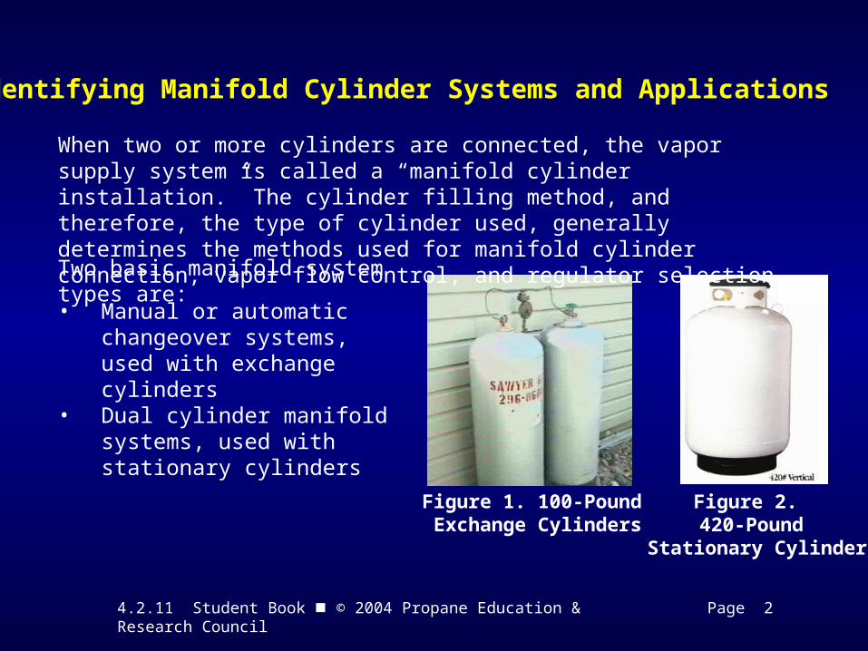
Figure 1. 100-Pound Exchange Cylinders
Figure 2. 420-Pound
Stationary Cylinder
When two or more cylinders are connected, the vapor supply system is called a “manifold cylinder installation.” The cylinder filling method, and therefore, the type of cylinder used, generally determines the methods used for manifold cylinder connection, vapor flow control, and regulator selection.
Two basic manifold system types are:
• Manual or automatic changeover systems, used with exchange cylinders
• Dual cylinder manifold systems, used with stationary cylinders
4.2.11 Student Book © 2004 Propane Education & Research Council Page 3
Identifying Manifold Cylinder Systems and Applications
Manual Changeover System— This manifold system relies on the customer to manually open and close the exchange cylinder service valves, or to switch over the valve in a connecting tee-block when the supply cylinder is empty and the reserve cylinder is needed.
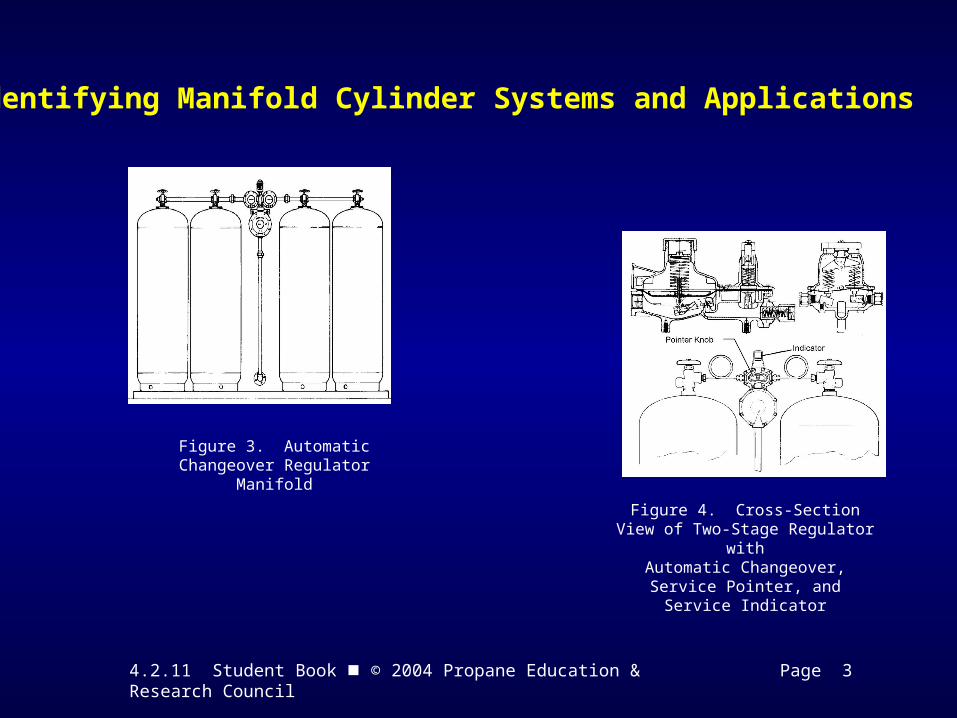
Automatic Changeover System— This cylinder manifold uses a special two-stage regulator combining the first stage and second stage into one unit. Normally this regulator is connected to two cylinders or two banks of cylinders (Figure 3). When the pressure in the supply cylinder(s) drops to a low level, the regulator automatically switches over to the reserve cylinder(s) and does not interrupt the supply to the appliances.
4.2.11 Student Book © 2004 Propane Education & Research Council Page 3
Identifying Manifold Cylinder Systems and Applications
Figure 3. Automatic Changeover Regulator Manifold
Figure 4. Cross-Section View of Two-Stage Regulator with
Automatic Changeover, Service Pointer, and Service Indicator
4.2.11 Student Book © 2004 Propane Education & Research Council Page 4
Identifying Manifold Cylinder Systems and Applications
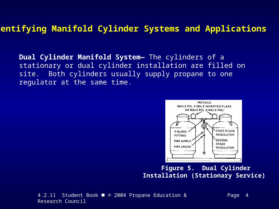
Figure 5. Dual CylinderInstallation (Stationary Service)
Dual Cylinder Manifold System— The cylinders of a stationary or dual cylinder installation are filled on site. Both cylinders usually supply propane to one regulator at the same time.
4.2.11 Student Book © 2004 Propane Education & Research Council Page 4
Selecting Components for Manifold Cylinder Systems
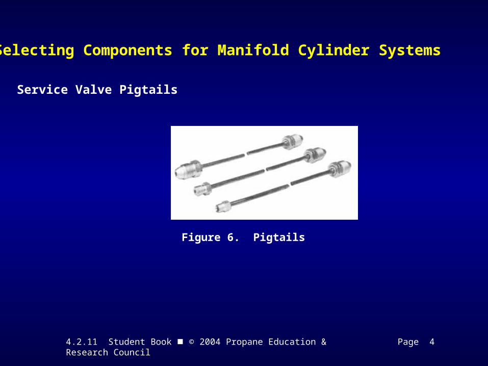
Figure 6. Pigtails
Service Valve Pigtails
4.2.11 Student Book © 2004 Propane Education & Research Council Page 5
Selecting T-Blocks for Manifold Cylinders
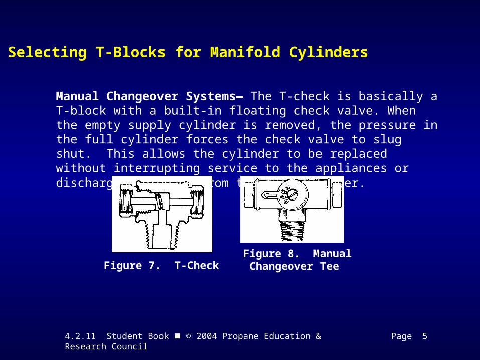
Figure 7. T-Check Figure 8. Manual Changeover Tee
Manual Changeover Systems— The T-check is basically a T-block with a built-in floating check valve. When the empty supply cylinder is removed, the pressure in the full cylinder forces the check valve to slug shut. This allows the cylinder to be replaced without interrupting service to the appliances or discharging propane from the full cylinder.
4.2.11 Student Book © 2004 Propane Education & Research Council Page 5
Selecting Components for Manifold Cylinder Systems
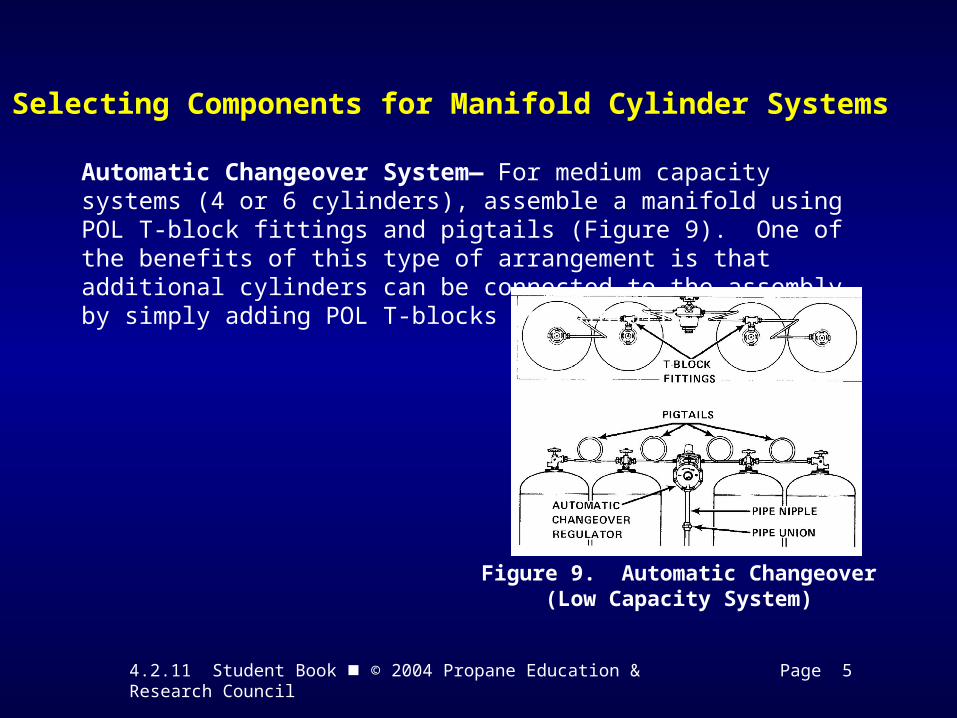
Figure 9. Automatic Changeover (Low Capacity System)
Automatic Changeover System— For medium capacity systems (4 or 6 cylinders), assemble a manifold using POL T-block fittings and pigtails (Figure 9). One of the benefits of this type of arrangement is that additional cylinders can be connected to the assembly by simply adding POL T-blocks and pigtails.
4.2.11 Student Book © 2004 Propane Education & Research Council Page 6
Selecting Components for Manifold Cylinder Systems
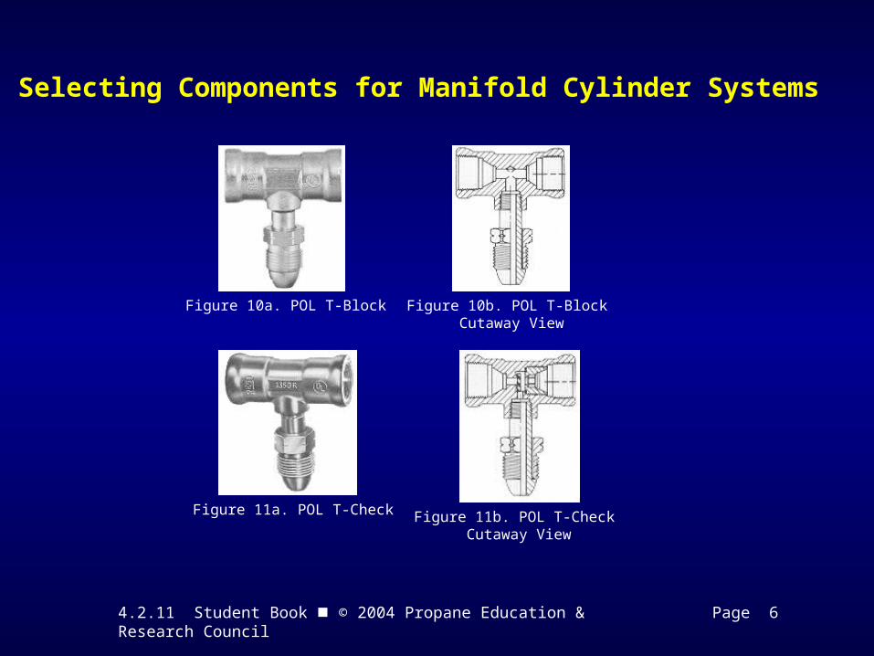
Figure 10a. POL T-Block Figure 10b. POL T-Block Cutaway View
Figure 11a. POL T-Check Figure 11b. POL T-Check Cutaway View
4.2.11 Student Book © 2004 Propane Education & Research Council Page 6
Selecting Components for Manifold Cylinder Systems
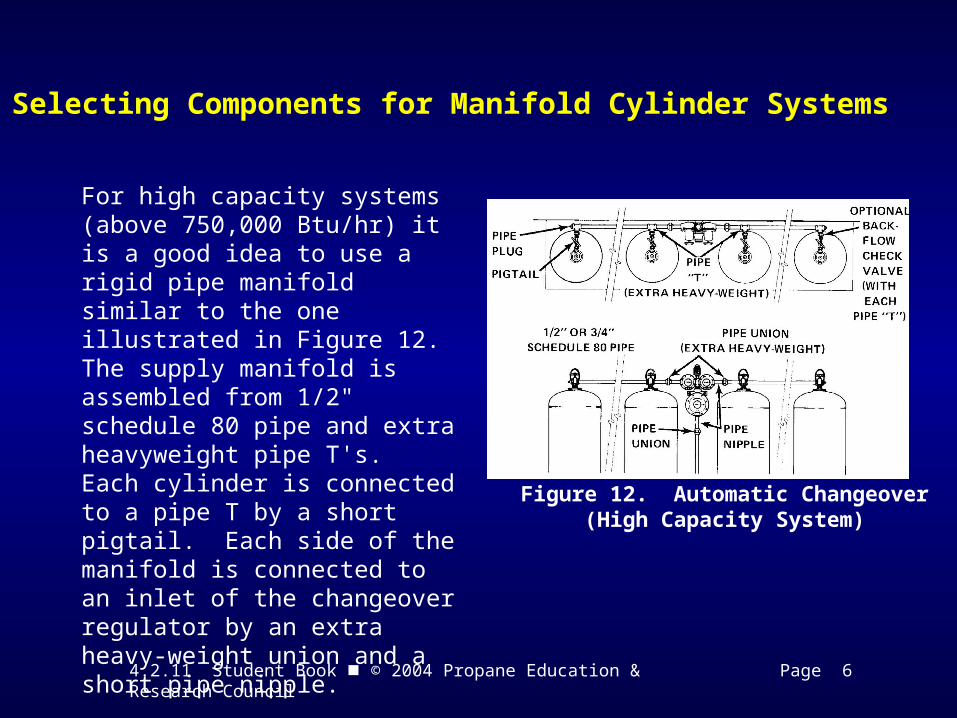
Figure 12. Automatic Changeover (High Capacity System)
For high capacity systems (above 750,000 Btu/hr) it is a good idea to use a rigid pipe manifold similar to the one illustrated in Figure 12. The supply manifold is assembled from 1/2" schedule 80 pipe and extra heavyweight pipe T's. Each cylinder is connected to a pipe T by a short pigtail. Each side of the manifold is connected to an inlet of the changeover regulator by an extra heavy-weight union and a short pipe nipple.
4.2.11 Student Book © 2004 Propane Education & Research Council Page 7
Selecting a Cylinder Manifold Pressure Regulator
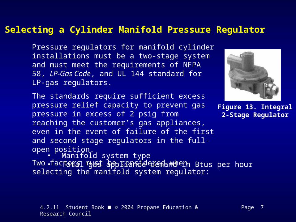
Figure 13. Integral 2-Stage Regulator
Pressure regulators for manifold cylinder installations must be a two-stage system and must meet the requirements of NFPA 58, LP-Gas Code, and UL 144 standard for LP-gas regulators.
The standards require sufficient excess pressure relief capacity to prevent gas pressure in excess of 2 psig from reaching the customer’s gas appliances, even in the event of failure of the first and second stage regulators in the full-open position.
Two factors must be considered when selecting the manifold system regulator:
• Manifold system type • Total gas appliance demand in Btus per hour
4.2.11 Student Book © 2004 Propane Education & Research Council Page 8
Selecting Components for Manifold Cylinder Systems
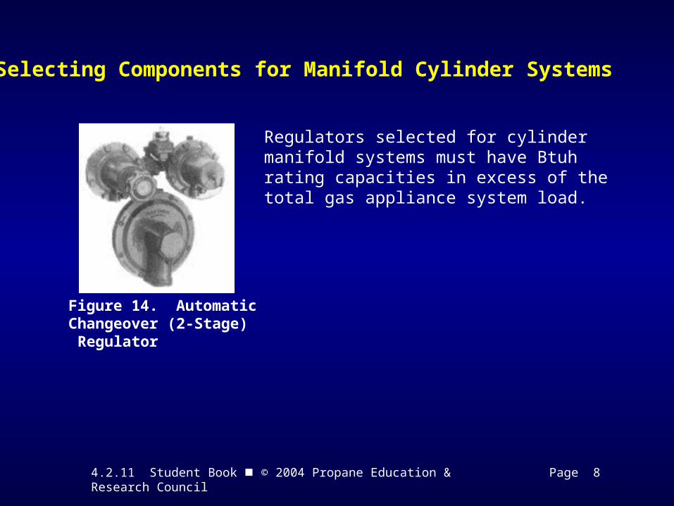
Figure 14. AutomaticChangeover (2-Stage) Regulator
Regulators selected for cylinder manifold systems must have Btuh rating capacities in excess of the total gas appliance system load.
4.2.11 Student Book © 2004 Propane Education & Research Council Page 9
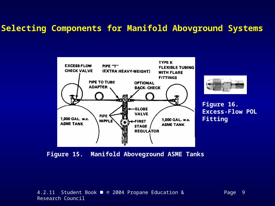
Selecting Components for Manifold Abovground Systems
Figure 15. Manifold Aboveground ASME Tanks
Figure 16. Excess-Flow POL Fitting
4.2.11 Student Book © 2004 Propane Education & Research Council Page 10
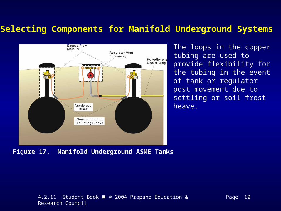
Selecting Components for Manifold Underground Systems
Figure 17. Manifold Underground ASME Tanks
The loops in the copper tubing are used to provide flexibility for the tubing in the event of tank or regulator post movement due to settling or soil frost heave.
4.2.11 Student Book © 2004 Propane Education & Research Council Page 10
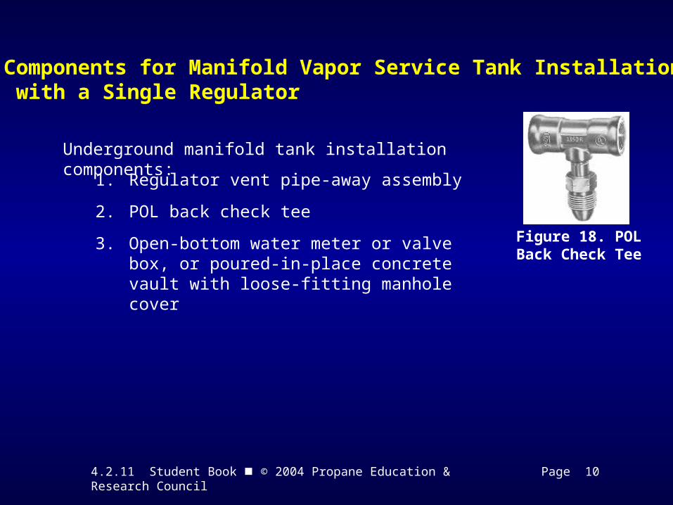
Components for Manifold Vapor Service Tank Installations with a Single Regulator
Figure 18. POL Back Check Tee
Underground manifold tank installation components:
1. Regulator vent pipe-away assembly
2. POL back check tee
3. Open-bottom water meter or valve box, or poured-in-place concrete vault with loose-fitting manhole cover
4.2.11 Student Book © 2004 Propane Education & Research Council Page 11
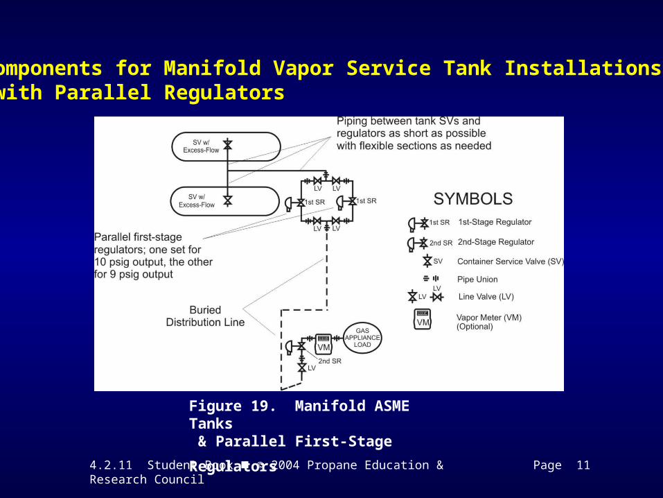
Components for Manifold Vapor Service Tank Installations with Parallel Regulators
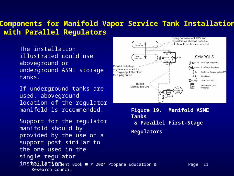
Figure 19. Manifold ASME Tanks
& Parallel First-Stage Regulators
4.2.11 Student Book © 2004 Propane Education & Research Council Page 11
Components for Manifold Vapor Service Tank Installations with Parallel Regulators
Figure 19. Manifold ASME Tanks
& Parallel First-Stage Regulators
The installation illustrated could use aboveground or underground ASME storage tanks.
If underground tanks are used, aboveground location of the regulator manifold is recommended.
Support for the regulator manifold should by provided by the use of a support post similar to the one used in the single regulator installation.

4.2.11 Student Book © 2004 Propane Education & Research Council Page 12
Identifying Code Requirements and Components for Manifold Tanks in Liquid Service
Figure 20. Excess- Flow Angle Valve
If the actuated liquid withdrawal excess-flow valve (sometimes called an evacuation valve) is used for manifold tank connection, one of two forms of excess-flow protection must be provided:
1. A liquid transfer valve attached to an actuated liquid withdrawal excess-flow valve that is recommended by the manufacturer for continuous service, or
2. If the tank’s evacuation valve is not approved for continuous service:
• The tank must be evacuated of liquid, and the vapor flared;• Tank vapor pressure reduced to atmospheric pressure;• The actuated liquid withdrawal excess-flow valve removed and
replaced with a liquid transfer valve equipped with an internal excess-flow
4.2.11 Student Book © 2004 Propane Education & Research Council Page 13
Identifying Code Requirements and Components forManifold Tanks in Liquid Service
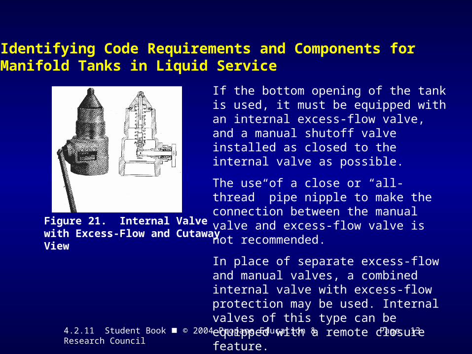
Figure 21. Internal Valve with Excess-Flow and Cutaway View
If the bottom opening of the tank is used, it must be equipped with an internal excess-flow valve, and a manual shutoff valve installed as closed to the internal valve as possible.
The use of a close or “all-thread” pipe nipple to make the connection between the manual valve and excess-flow valve is not recommended.
In place of separate excess-flow and manual valves, a combined internal valve with excess-flow protection may be used. Internal valves of this type can be equipped with a remote closure feature.
4.2.11 Student Book © 2004 Propane Education & Research Council Page 13
Identifying Code Requirements and Components forManifold Tanks in Liquid Service
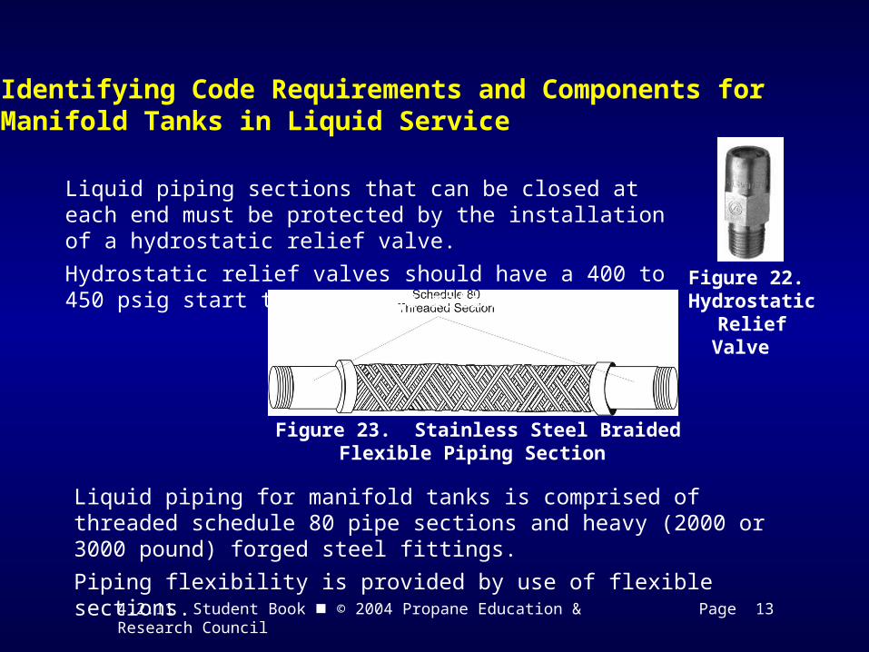
Figure 22. Hydrostatic Relief Valve
Figure 23. Stainless Steel BraidedFlexible Piping Section
Liquid piping sections that can be closed at each end must be protected by the installation of a hydrostatic relief valve.
Hydrostatic relief valves should have a 400 to 450 psig start to discharge rating.
Liquid piping for manifold tanks is comprised of threaded schedule 80 pipe sections and heavy (2000 or 3000 pound) forged steel fittings.
Piping flexibility is provided by use of flexible sections.
4.2.11 Student Book © 2004 Propane Education & Research Council Page 14
Identifying Code Requirements and Components forManifold Tanks in Liquid Service
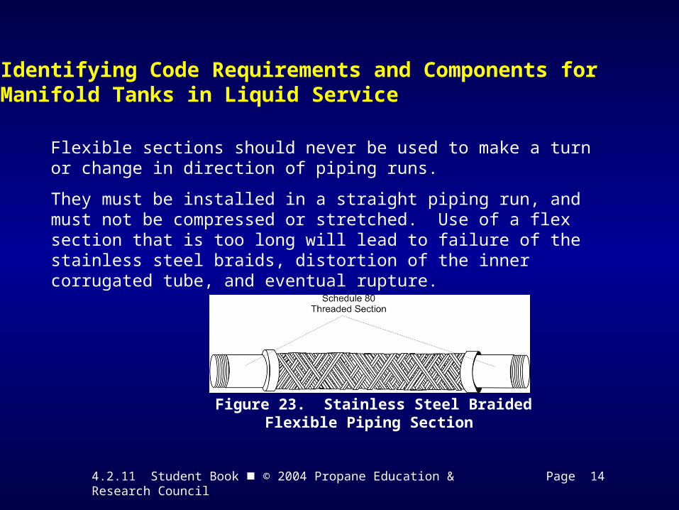
Figure 23. Stainless Steel BraidedFlexible Piping Section
Flexible sections should never be used to make a turn or change in direction of piping runs.
They must be installed in a straight piping run, and must not be compressed or stretched. Use of a flex section that is too long will lead to failure of the stainless steel braids, distortion of the inner corrugated tube, and eventual rupture.
4.2.11 Student Book © 2004 Propane Education & Research Council Page 14
Identifying Code Requirements and Components forManifold Tanks in Liquid Service
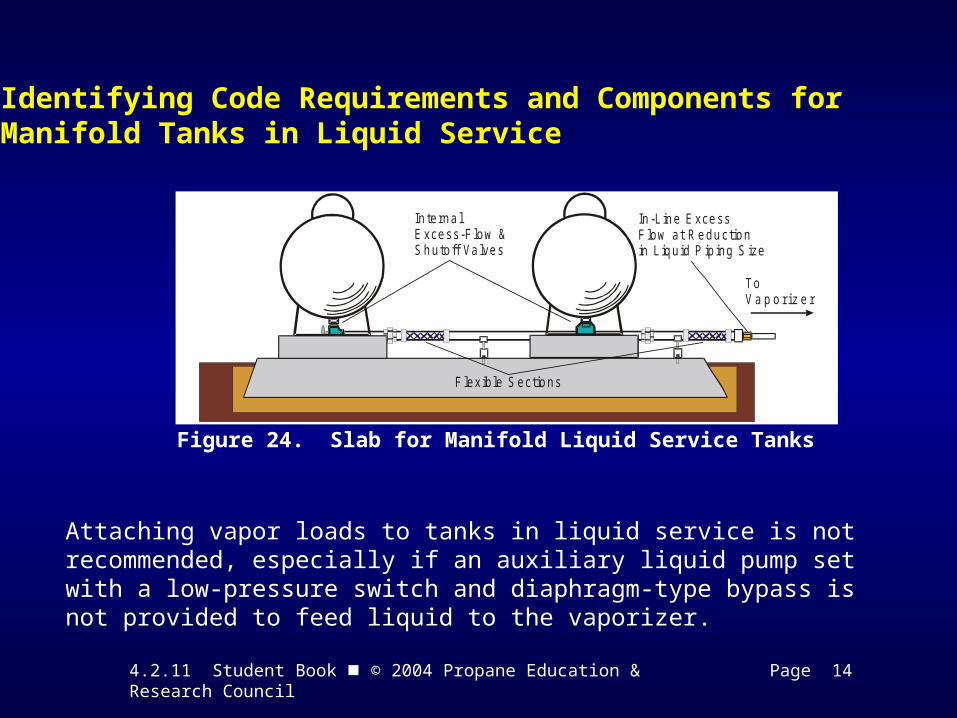
Figure 24. Slab for Manifold Liquid Service Tanks
ToV a p o r i z e r
In-L ine ExcessF low at Reductionin L iquid P ip ing S ize
Interna lExcess-Flow &Shutoff Valves
F lex ible S ections
Attaching vapor loads to tanks in liquid service is not recommended, especially if an auxiliary liquid pump set with a low-pressure switch and diaphragm-type bypass is not provided to feed liquid to the vaporizer.
4.2.11 Student Book © 2004 Propane Education & Research Council Pages 15 - 20
Time to See If You Got the Key Points of This Module…
• Complete the Review on pages 15 - 17.
• See if you are ready for the Certification Exam by checking off the performance criteria on pages 18 - 20.