Embed Size (px)
Citation preview
APPLICATION GUIDE
74-2949-3
CARE/E-Vision
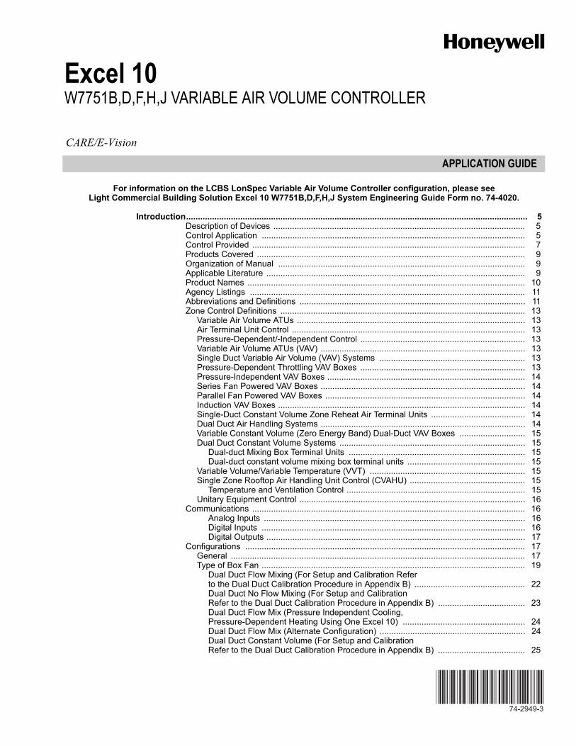
Excel 10W7751B,D,F,H,J VARIABLE AIR VOLUME CONTROLLER
For information on the LCBS LonSpec Variable Air Volume Controller configuration, please see Light Commercial Building Solution Excel 10 W7751B,D,F,H,J System Engineering Guide Form no. 74-4020.
Introduction ................................................................................................................................................. 5Description of Devices ........................................................................................................... 5Control Application ................................................................................................................ 5Control Provided .................................................................................................................... 7Products Covered .................................................................................................................. 9Organization of Manual ......................................................................................................... 9Applicable Literature .............................................................................................................. 9Product Names ...................................................................................................................... 10Agency Listings ..................................................................................................................... 11Abbreviations and Definitions ................................................................................................ 11Zone Control Definitions ........................................................................................................ 13
Variable Air Volume ATUs ................................................................................................. 13Air Terminal Unit Control ................................................................................................... 13Pressure-Dependent/-Independent Control ...................................................................... 13Variable Air Volume ATUs (VAV) ....................................................................................... 13Single Duct Variable Air Volume (VAV) Systems .............................................................. 13Pressure-Dependent Throttling VAV Boxes ...................................................................... 13Pressure-Independent VAV Boxes .................................................................................... 14Series Fan Powered VAV Boxes ....................................................................................... 14Parallel Fan Powered VAV Boxes ..................................................................................... 14Induction VAV Boxes ......................................................................................................... 14Single-Duct Constant Volume Zone Reheat Air Terminal Units ........................................ 14Dual Duct Air Handling Systems ....................................................................................... 14Variable Constant Volume (Zero Energy Band) Dual-Duct VAV Boxes ............................ 15Dual Duct Constant Volume Systems ............................................................................... 15
Dual-duct Mixing Box Terminal Units ........................................................................... 15Dual-duct constant volume mixing box terminal units .................................................. 15
Variable Volume/Variable Temperature (VVT) .................................................................. 15Single Zone Rooftop Air Handling Unit Control (CVAHU) ................................................. 15
Temperature and Ventilation Control ............................................................................ 15Unitary Equipment Control ................................................................................................ 16
Communications .................................................................................................................... 16Analog Inputs ............................................................................................................... 16Digital Inputs ................................................................................................................ 16Digital Outputs .............................................................................................................. 17
Configurations ....................................................................................................................... 17General ............................................................................................................................. 17Type of Box Fan ................................................................................................................ 19
Dual Duct Flow Mixing (For Setup and Calibration Refer to the Dual Duct Calibration Procedure in Appendix B) ............................................... 22Dual Duct No Flow Mixing (For Setup and Calibration Refer to the Dual Duct Calibration Procedure in Appendix B) ..................................... 23Dual Duct Flow Mix (Pressure Independent Cooling, Pressure-Dependent Heating Using One Excel 10) .................................................... 24Dual Duct Flow Mix (Alternate Configuration) .............................................................. 24Dual Duct Constant Volume (For Setup and Calibration Refer to the Dual Duct Calibration Procedure in Appendix B) ..................................... 25
EXCEL 10 W7751B,D,F,H,J VARIABLE AIR VOLUME CONTROLLER
74-2949—3 2
Dual Duct Press Flow Mix (Pressure-Dependent Cooling and Heating Using One Excel 10) ................................................................... 26Dual Duct Press Flow Mix (Alternate Configuration) .................................................... 26Dual Duct Discharge Sensor Constant Volume (Pressure-Independent Discharge Using One Excel 10) .............................................. 26Dual Duct Press Flow Mix (Pressure-Dependent Cooling and Heating Using One Excel 10) ................................................................................ 27Dual Duct Pressure-Independent (Pressure-Independent Cooling and Heating Using One Excel 10) ................................................................... 27PWM fan ....................................................................................................................... 28Exhaust Tracking Flow Control ..................................................................................... 28Share Wall Module ........................................................................................................ 29
Type of Reheat Coil ........................................................................................................... 30Pneumatic Valve Actuator Control ................................................................................ 31
Exhaust Tracking Option ................................................................................................... 31Occupancy Sensor ............................................................................................................ 31Window Open/Closed Digital Input .................................................................................... 32Heat/Cool Change Over .................................................................................................... 32Wall Module Options .......................................................................................................... 32
Common Temperature Control (Share Wall Module) .................................................... 32Sensor Options .................................................................................................................. 32Pneumatic Retrofit Applications ......................................................................................... 33
Application Process ................................................................................................................................................ 33Overview ................................................................................................................................ 33Step 1. Create Bill of Materials ............................................................................................... 33Step 2. Configure Controllers ................................................................................................. 33
Default Hardware Configuration ........................................................................................ 33Configuration Screens for VAV Controllers ........................................................................ 34
Tab: Configuration ......................................................................................................... 34Tab: Input ...................................................................................................................... 37Tab: Control Parameters ............................................................................................... 37Tab: Pickup Table .......................................................................................................... 39Tab: PID ........................................................................................................................ 39Tab: Misc Parameters ................................................................................................... 39Tab: Wiring .................................................................................................................... 41
Commissioning .................................................................................................................. 41ID Number .................................................................................................................... 41
Step 3. Troubleshooting .......................................................................................................... 41Troubleshooting Excel 10 Controllers and Wall Modules .................................................. 41Temperature Sensor and Setpoint Potentiometer Resistance Ranges ............................. 41Alarms ............................................................................................................................... 41Broadcasting the Service Message ................................................................................... 42
Appendices ................................................................................................................................................ 43Appendix A. Creating a Work Bench for Configuring Excel 10 W7751D,F VAV Controllers. . 43Appendix B. Using E-Vision to Commission a W7751 Controller. .......................................... 43
Job Commissioning ........................................................................................................... 43ID Number ......................................................................................................................... 43
Bench Top Configuring ................................................................................................. 43Configuring in the Field ................................................................................................. 43Configuring the Zone Manager ..................................................................................... 44
Sensor Calibration ............................................................................................................. 44Procedure ..................................................................................................................... 44
Air Flow Balancing (For Pressure Independent applications only) .................................... 44Procedure ..................................................................................................................... 44Resetting Air Flow Calibration to Factory Defaults ....................................................... 44
VAVII Calibration Sequence ............................................................................................... 44Appendix C. Sequences of Operation. ................................................................................... 46
Common Operations. ........................................................................................................ 46Room Temperature Sensor (RmTemp) ......................................................................... 46Remote Setpoint ........................................................................................................... 47Setpoint Limits (StptLoLim and StptHiLim) ................................................................... 47Bypass Mode (StatusOvrride and StatusLed) ............................................................... 47BypassTime .................................................................................................................. 47OverrideType ................................................................................................................ 47Override Priority ............................................................................................................ 47
Excel 10 W7751B,D,F,H,J Vari-able Air Vol-ume Controller
EXCEL 10 W7751B,D,F,H,J VARIABLE AIR VOLUME CONTROLLER
3 74-2949—3
Standby Mode ............................................................................................................... 47Window Sensor ............................................................................................................ 47CAV Control .................................................................................................................. 48Continuous Unoccupied Mode ..................................................................................... 48Share Wall Module ....................................................................................................... 48Night Purge ................................................................................................................... 48Morning Warm-Up ........................................................................................................ 48Smoke Control .............................................................................................................. 48Demand Limit Control ................................................................................................... 48Start-Up ........................................................................................................................ 48Air Flow Control Sequences of Operation .................................................................... 48
Dual Duct, Pressure Independent, with flow mixing, with cold and hot duct flow pickups (uses a satellite Excel 10 for hot duct). ....................................................................................... 49
Dual Duct Flow Mixing: (For setup and Calibration refer to the Dual Duct Calibration proce-dure in Appendix B) ...................................................................................................... 49
Dual Duct, Pressure Independent, without flow mixing, with cold and hot duct flow pickups (uses a satellite Excel 10 for hot duct). ............................................................................. 49
Dual Duct No Flow Mixing: (For setup and Calibration refer to the Dual Duct Calibration procedure in Appendix B) ............................................................................................. 49
Dual Duct, Pressure Independent cooling, Pressure Dependent heating with flow mixing, with cold duct flow pickup. ........................................................................................................ 50
Dual Duct Press Flow Mix (Pressure Independent Cooling and Pressure Dependent Heat-ing using one Excel 10). ............................................................................................... 50Dual Duct Press Flow Mix: (Alternate Configuration) ................................................... 50
Dual Duct, Pressure Independent cooling and heating, constant volume with hot and cold duct flow pickups. .............................................................................................................. 50
Dual Duct Constant Volume: ......................................................................................... 50Dual Duct, Pressure Dependent cooling and heating, with Flow mixing and no flow pickups. 51
Dual Duct Press Flow Mix (pressure dependent cooling and heating using one Excel 10). 51
Dual Duct, Pressure Independent cooling and Pressure Dependent heating, with Constant Volume and Discharge Air Flow pickup. ............................................................................ 51
Dual Duct Discharge Sensor Constant Volume(pressure dependent cooling and heating using one Excel 10). ................................... 51
Appendix D. Complete List of Excel 10 VAVII User Addresses .............................................. 52Appendix E. Q7750A Excel 10 Zone Manager Point Estimating Guide .................................115
Approximate Memory Size Estimating Procedure. ............................................................115Appendix F. Customer Flow Pickup Tables (not Applicable for Pressure Dependent Applica-tions). .....................................................................................................................................116
Method 1. Pressure Velocity Formulas ..............................................................................116Method 2. Pressure Versus Flow Graph ...........................................................................116

EXCEL 10 W7751B,D,F,H,J VARIABLE AIR VOLUME CONTROLLER
74-2949—3 4
EXCEL 10 W7751B,D,F,H,J VARIABLE AIR VOLUME CONTROLLER
5 74-2949—3
INTRODUCTION
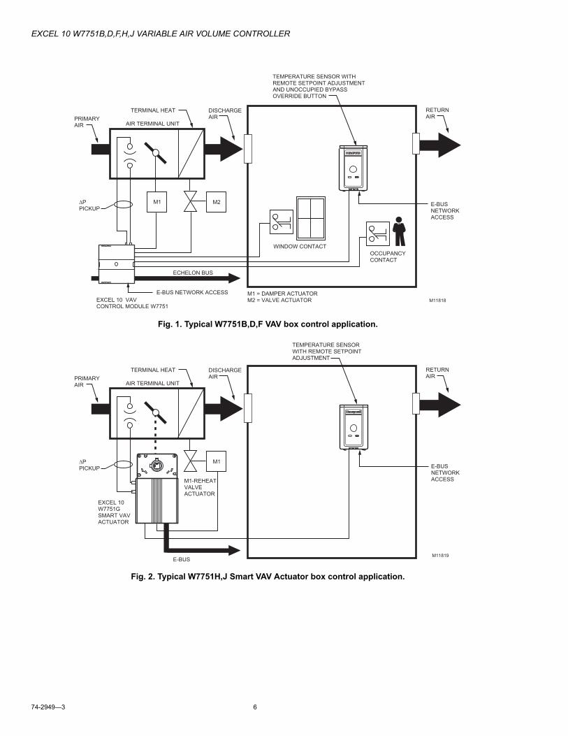
Description of DevicesThe W7751B,D,F,H,J Excel 10 VAVII Box Controllers provide enhanced control solutions for single duct, dual duct and constant volume air terminal units. The controllers feature preprogrammed heating/cooling or reheat control algorithms for standard VAV Box control applications that are selected through the E-Vision software configuration tool. Additionally, the VAVII controllers use Echelon® LONWORKS® communication technology and the new Free Topology Transceiver (FTT) for greater installation flexibility. The Excel 10 VAVII Box Controllers are the first VAV Box Controllers in the marketplace from any manufacturer that use the LONMARK® VAV Controller compliance profile for true openness and interoperability with third party LONMARK devices. The controllers can be used in stand-alone applications or can be used in combination with Excel 10 Zone Manager (FTT), other Excel Controllers, and the Excel Building Supervisor to provided a complete and low cost control solution for light commercial buildings.
The W7751B,D,F,H,J Excel 10 VAV Box Controllers are configurable direct digital controllers designed for pressure independent or pressure dependent single duct VAV, dual duct VAV and constant volume air terminal unit control solutions. Five models are available including a low cost circuit board OEM version (W7751B) for internal panel mounting, two plenum mounted controllers complete with a wiring subbase for easy field installation (W7751D and F) and the low cost Smart VAV Actuators (W7751H and J) consisting of the Excel 10 Controller that is factory mounted and wired to a 90 second ML6161B Actuator. The W7751B,D,F, and H Excel 10 VAV Box Controllers contain an integral microbridge air flow sensor that provides flow measurement for pressure independent applications. The W7751J does not contain an air flow sensor, and is therefore for pressure dependent applications only. The controller configuration for all VAVII controllers is selected using a personal computer and the configuration tool. The Excel 10 VAV Box Controllers offer many features required in today’s commercial buildings including energy saving setpoint reset for electrical demand limit control, standby setpoints for setpoint reset in the occupied mode and unoccupied setpoints for both heating and cooling. The control solutions are scalable from stand-alone installations to a networked system using a Zone Manager as the network master or they can be fully integrated into the complete Excel 5000 system with Excel 100, 500 and 600.
In addition, the Excel 10 VAVII Box Controllers provide true open communication with the use of the LONMARK Controller compliance profile and the FTT for greater flexibility in network wiring and integration with third party LONMARK® devices.
The T7770 are direct-wired wall modules used in conjunction with W7751B,D,F,H,J Controllers. The zone controlled by the W7751 Controllers will typically use a T7770 Wall Module with a temperature sensor for space temperature measurement in a minimum system configuration. Additional features available in the T7770 model include analog setpoint input, override digital input pushbutton, override status LED and LONWORKS Bus network access jack.
The T7790C used in conjunction with the Q7790A receiver uses wireless technology to communicate space temperature, setpoint, and manual occupancy override information to the W7751B,D,F,H, and J Controllers.
The C7770A Air Temperature Sensor is a direct wired temperature sensor that is used to sense discharge or return air in a duct controlled by a W7751 Controller.
The Q7750A Excel 10 Zone Manager is a communications interface that allows devices on the E-Bus network to communicate with devices on the EXCEL 5000™ System C-Bus.
The Q7750A also provides some control and monitoring functions.
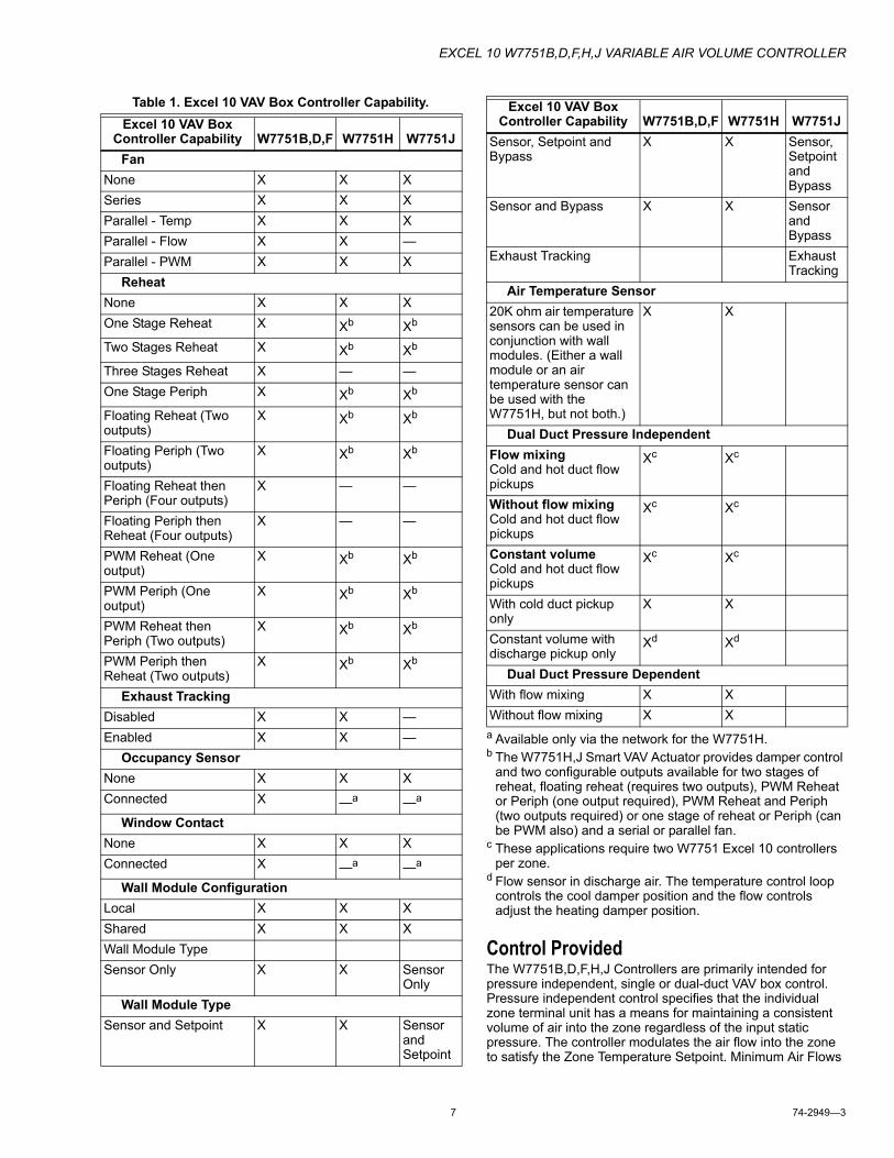
Control ApplicationVAV systems in commercial buildings typically incorporate a central air handler that delivers a modulated volume of air at a preconditioned temperature to multiple zones. Each zone is serviced by a VAV terminal box unit. Each box incorporates an air flow pickup assembly and motorized damper with optional fan and/or reheat coil. The controller determines and regulates the air flow of conditioned air to the space. The zone being fed by the terminal box will use a T7770 Wall Module, or a T7790 Wireless Wall Module for space temperature determination and access to the LONWORKS Bus network for operators. Fig. 1 shows a typical VAV box control application for the W7751B,D,F Controllers. Fig. 2 shows a typical VAV box control application for the W7751H Smart VAV Actuator. The W7751J Smart VAV Actuator has an application similar to Fig. 2 with no onboard air flow sensor (Pressure dependent applications). Table 1 shows the capabilities of the Excel 10 VAV Box Controllers.
Excel10
W7751B,D,F,H,JVari-able
AirVol-umeCon-
troller
EXCEL 10 W7751B,D,F,H,J VARIABLE AIR VOLUME CONTROLLER
74-2949—3 6
Fig. 1. Typical W7751B,D,F VAV box control application.
Fig. 2. Typical W7751H,J Smart VAV Actuator box control application.
ΔPPICKUP
M1 M2
EXCEL 10 VAVCONTROL MODULE W7751
WINDOW CONTACT
ECHELON BUS
OCCUPANCYCONTACT
DISCHARGE AIR
TERMINAL HEAT
AIR TERMINAL UNITPRIMARY AIR
M1 = DAMPER ACTUATORM2 = VALVE ACTUATOR
TEMPERATURE SENSOR WITHREMOTE SETPOINT ADJUSTMENT AND UNOCCUPIED BYPASSOVERRIDE BUTTON
RETURNAIR
M11818
E-BUS NETWORK ACCESS
E-BUS NETWORK ACCESS
ΔPPICKUP
M1
E-BUS
DISCHARGE AIR
TERMINAL HEAT
AIR TERMINAL UNITPRIMARY AIR
M1-REHEATVALVE ACTUATOR
TEMPERATURE SENSOR WITH REMOTE SETPOINT ADJUSTMENT
RETURNAIR
M11819
E-BUS NETWORK ACCESS
EXCEL 10 W7751GSMART VAV ACTUATOR
EXCEL 10 W7751B,D,F,H,J VARIABLE AIR VOLUME CONTROLLER
7 74-2949—3
Table 1. Excel 10 VAV Box Controller Capability.
a Available only via the network for the W7751H.b The W7751H,J Smart VAV Actuator provides damper control
and two configurable outputs available for two stages of reheat, floating reheat (requires two outputs), PWM Reheat or Periph (one output required), PWM Reheat and Periph (two outputs required) or one stage of reheat or Periph (can be PWM also) and a serial or parallel fan.
c These applications require two W7751 Excel 10 controllers per zone.
d Flow sensor in discharge air. The temperature control loop controls the cool damper position and the flow controls adjust the heating damper position.
Control ProvidedThe W7751B,D,F,H,J Controllers are primarily intended for pressure independent, single or dual-duct VAV box control. Pressure independent control specifies that the individual zone terminal unit has a means for maintaining a consistent volume of air into the zone regardless of the input static pressure. The controller modulates the air flow into the zone to satisfy the Zone Temperature Setpoint. Minimum Air Flows
Excel 10 VAV Box Controller Capability W7751B,D,F W7751H W7751J
FanNone X X XSeries X X XParallel - Temp X X XParallel - Flow X X —Parallel - PWM X X X
ReheatNone X X XOne Stage Reheat X Xb Xb
Two Stages Reheat X Xb Xb
Three Stages Reheat X — —One Stage Periph X Xb Xb
Floating Reheat (Two outputs)
X Xb Xb
Floating Periph (Two outputs)
X Xb Xb
Floating Reheat then Periph (Four outputs)
X — —
Floating Periph then Reheat (Four outputs)
X — —
PWM Reheat (One output)
X Xb Xb
PWM Periph (One output)
X Xb Xb
PWM Reheat then Periph (Two outputs)
X Xb Xb
PWM Periph then Reheat (Two outputs)
X Xb Xb
Exhaust TrackingDisabled X X —Enabled X X —
Occupancy SensorNone X X XConnected X —a —a
Window ContactNone X X XConnected X —a —a
Wall Module ConfigurationLocal X X XShared X X XWall Module TypeSensor Only X X Sensor
OnlyWall Module Type
Sensor and Setpoint X X Sensor and Setpoint
Sensor, Setpoint and Bypass
X X Sensor, Setpoint and Bypass
Sensor and Bypass X X Sensor and Bypass
Exhaust Tracking Exhaust Tracking
Air Temperature Sensor20K ohm air temperature sensors can be used in conjunction with wall modules. (Either a wall module or an air temperature sensor can be used with the W7751H, but not both.)
X X
Dual Duct Pressure IndependentFlow mixingCold and hot duct flow pickups
Xc Xc
Without flow mixingCold and hot duct flow pickups
Xc Xc
Constant volumeCold and hot duct flow pickups
Xc Xc
With cold duct pickup only
X X
Constant volume with discharge pickup only
Xd Xd
Dual Duct Pressure DependentWith flow mixing X XWithout flow mixing X X
Excel 10 VAV Box Controller Capability W7751B,D,F W7751H W7751J
EXCEL 10 W7751B,D,F,H,J VARIABLE AIR VOLUME CONTROLLER
74-2949—3 8
are maintained except during emergency strategy periods or during building Unoccupied periods if using physical position stops, a MIN/MAX air flow is always maintained (see Table 2).
Pressure dependent control specifies that the damper position is controlled by space temperature only and not by a measurement of air flow volume. The amount of air delivered to the zone at any given damper position is dependent on the static pressure in the supply air duct (physical position stops, range stop pins, are used to keep the damper at a fixed position).
VAV systems generally only provide cool air to the zones; therefore, the W7751 Controller provides additional outputs for control of heating systems such as reheat coils for Heat mode or Morning warm-up mode operation. The heating equipment can be staged-resistive heating, staged 2-position (solenoid) valve, or modulated steam or hot water valve.
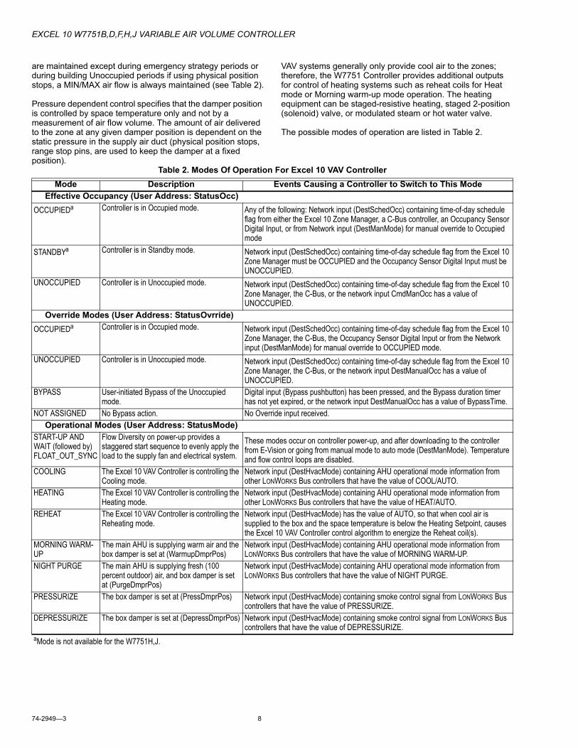
The possible modes of operation are listed in Table 2.
Table 2. Modes Of Operation For Excel 10 VAV ControllerMode Description Events Causing a Controller to Switch to This Mode
Effective Occupancy (User Address: StatusOcc)OCCUPIEDa Controller is in Occupied mode. Any of the following: Network input (DestSchedOcc) containing time-of-day schedule
flag from either the Excel 10 Zone Manager, a C-Bus controller, an Occupancy Sensor Digital Input, or from Network input (DestManMode) for manual override to Occupied mode
STANDBYa Controller is in Standby mode. Network input (DestSchedOcc) containing time-of-day schedule flag from the Excel 10 Zone Manager must be OCCUPIED and the Occupancy Sensor Digital Input must be UNOCCUPIED.
UNOCCUPIED Controller is in Unoccupied mode. Network input (DestSchedOcc) containing time-of-day schedule flag from the Excel 10 Zone Manager, the C-Bus, or the network input CmdManOcc has a value of UNOCCUPIED.
Override Modes (User Address: StatusOvrride)OCCUPIEDa Controller is in Occupied mode. Network input (DestSchedOcc) containing time-of-day schedule flag from the Excel 10
Zone Manager, the C-Bus, the Occupancy Sensor Digital Input or from the Network input (DestManMode) for manual override to OCCUPIED mode.
UNOCCUPIED Controller is in Unoccupied mode. Network input (DestSchedOcc) containing time-of-day schedule flag from the Excel 10 Zone Manager, the C-Bus, or the network input DestManualOcc has a value of UNOCCUPIED.
BYPASS User-initiated Bypass of the Unoccupied mode.
Digital input (Bypass pushbutton) has been pressed, and the Bypass duration timer has not yet expired, or the network input DestManualOcc has a value of BypassTime.
NOT ASSIGNED No Bypass action. No Override input received.Operational Modes (User Address: StatusMode)
START-UP AND WAIT (followed by) FLOAT_OUT_SYNC
Flow Diversity on power-up provides a staggered start sequence to evenly apply the load to the supply fan and electrical system.
These modes occur on controller power-up, and after downloading to the controller from E-Vision or going from manual mode to auto mode (DestManMode). Temperature and flow control loops are disabled.
COOLING The Excel 10 VAV Controller is controlling the Cooling mode.
Network input (DestHvacMode) containing AHU operational mode information from other LONWORKS Bus controllers that have the value of COOL/AUTO.
HEATING The Excel 10 VAV Controller is controlling the Heating mode.
Network input (DestHvacMode) containing AHU operational mode information from other LONWORKS Bus controllers that have the value of HEAT/AUTO.
REHEAT The Excel 10 VAV Controller is controlling the Reheating mode.
Network input (DestHvacMode) has the value of AUTO, so that when cool air is supplied to the box and the space temperature is below the Heating Setpoint, causes the Excel 10 VAV Controller control algorithm to energize the Reheat coil(s).
MORNING WARM-UP
The main AHU is supplying warm air and the box damper is set at (WarmupDmprPos)
Network input (DestHvacMode) containing AHU operational mode information from LONWORKS Bus controllers that have the value of MORNING WARM-UP.
NIGHT PURGE The main AHU is supplying fresh (100 percent outdoor) air, and box damper is set at (PurgeDmprPos)
Network input (DestHvacMode) containing AHU operational mode information from LONWORKS Bus controllers that have the value of NIGHT PURGE.
PRESSURIZE The box damper is set at (PressDmprPos) Network input (DestHvacMode) containing smoke control signal from LONWORKS Bus controllers that have the value of PRESSURIZE.
DEPRESSURIZE The box damper is set at (DepressDmprPos) Network input (DestHvacMode) containing smoke control signal from LONWORKS Bus controllers that have the value of DEPRESSURIZE.
aMode is not available for the W7751H,J.
EXCEL 10 W7751B,D,F,H,J VARIABLE AIR VOLUME CONTROLLER
9 74-2949—3
Products CoveredThis System Engineering Guide describes how to apply the Excel 10 family of W7751 VAV Controllers and related accessories to typical applications. The specific devices covered include:• W7751B,D,F,H,J Controllers.• T7770A through D Wall Modules.• T7790C/Q7790A Wireless Wall Module• Q7752A Serial Adapter.• Q7740A,B FTT Repeaters.• 209541B FTT Termination Module.
Organization of ManualThis manual is divided into three basic parts: the Introduction, the Application Process, and the Appendices that provide supporting information. The organization of the manual assumes a project is being engineered from start to finish. If an operator is adding to, or is changing an existing system, the Table of Contents can provide the relevant information.
Applicable LiteratureThe following list of documents contains information related to the Excel 10 family of VAV Box Controllers and the EXCEL 5000™ System in general.
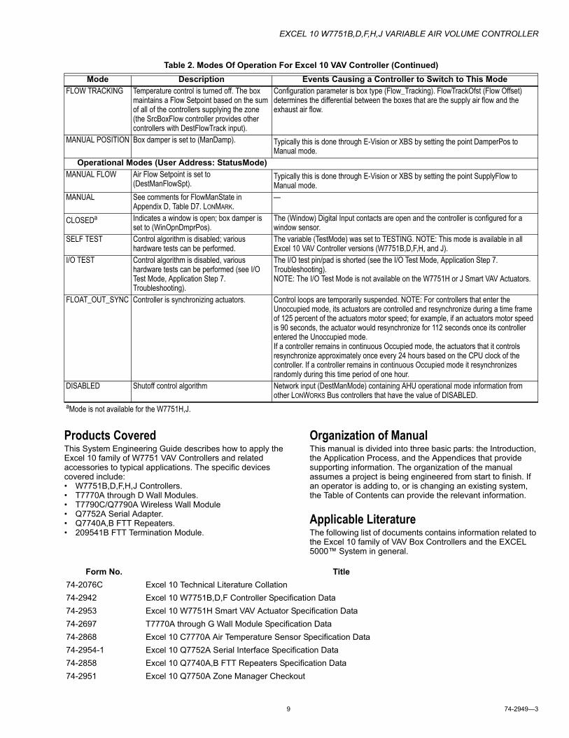
FLOW TRACKING Temperature control is turned off. The box maintains a Flow Setpoint based on the sum of all of the controllers supplying the zone (the SrcBoxFlow controller provides other controllers with DestFlowTrack input).
Configuration parameter is box type (Flow_Tracking). FlowTrackOfst (Flow Offset) determines the differential between the boxes that are the supply air flow and the exhaust air flow.
MANUAL POSITION Box damper is set to (ManDamp). Typically this is done through E-Vision or XBS by setting the point DamperPos to Manual mode.
Operational Modes (User Address: StatusMode)MANUAL FLOW Air Flow Setpoint is set to
(DestManFlowSpt).Typically this is done through E-Vision or XBS by setting the point SupplyFlow to Manual mode.
MANUAL See comments for FlowManState in Appendix D, Table D7. LONMARK.
—
CLOSEDa Indicates a window is open; box damper is set to (WinOpnDmprPos).
The (Window) Digital Input contacts are open and the controller is configured for a window sensor.
SELF TEST Control algorithm is disabled; various hardware tests can be performed.
The variable (TestMode) was set to TESTING. NOTE: This mode is available in all Excel 10 VAV Controller versions (W7751B,D,F,H, and J).
I/O TEST Control algorithm is disabled, various hardware tests can be performed (see I/O Test Mode, Application Step 7. Troubleshooting).
The I/O test pin/pad is shorted (see the I/O Test Mode, Application Step 7. Troubleshooting).NOTE: The I/O Test Mode is not available on the W7751H or J Smart VAV Actuators.
FLOAT_OUT_SYNC Controller is synchronizing actuators. Control loops are temporarily suspended. NOTE: For controllers that enter the Unoccupied mode, its actuators are controlled and resynchronize during a time frame of 125 percent of the actuators motor speed; for example, if an actuators motor speed is 90 seconds, the actuator would resynchronize for 112 seconds once its controller entered the Unoccupied mode.If a controller remains in continuous Occupied mode, the actuators that it controls resynchronize approximately once every 24 hours based on the CPU clock of the controller. If a controller remains in continuous Occupied mode it resynchronizes randomly during this time period of one hour.
DISABLED Shutoff control algorithm Network input (DestManMode) containing AHU operational mode information from other LONWORKS Bus controllers that have the value of DISABLED.
Table 2. Modes Of Operation For Excel 10 VAV Controller (Continued)Mode Description Events Causing a Controller to Switch to This Mode
aMode is not available for the W7751H,J.
Form No. Title74-2076C Excel 10 Technical Literature Collation74-2942 Excel 10 W7751B,D,F Controller Specification Data74-2953 Excel 10 W7751H Smart VAV Actuator Specification Data74-2697 T7770A through G Wall Module Specification Data74-2868 Excel 10 C7770A Air Temperature Sensor Specification Data74-2954-1 Excel 10 Q7752A Serial Interface Specification Data74-2858 Excel 10 Q7740A,B FTT Repeaters Specification Data74-2951 Excel 10 Q7750A Zone Manager Checkout
EXCEL 10 W7751B,D,F,H,J VARIABLE AIR VOLUME CONTROLLER
74-2949—3 10
Product NamesThe W7751 Controller is available in five models:• W7751B VAV Box Controller for OEM mounting on a VAV
box.• W7751D VAV Box Controller mounts on either a standard 4
in. by 4 in. electrical junction box or a standard 5 in. by 5 in. electrical junction box (wire passes through junction box to wiring subbase). It can also be snapped onto standard EN 50 022 DIN rail 35 mm by 7.5 mm (1-3/8 in. by 5/16 in.).
• W7751F VAV Box Controller mounts into either a panel with screws or snaps onto standard EN 50 022 DIN rail 35 mm by 7.5 mm (1-3/8 in. by 5/16 in.). Wires are terminated externally to wiring subbase.
• W7751H and J Smart VAV Actuators are VAV controllers that are factory mounted to an ML6161B1000 Actuator. The actuator/controller assembly is field mounted to the VAV box damper shaft similar to the mounting of a standard actuator, and the controller wiring is terminated to the screw terminals that are located under a snap-on cover. The W7751J does not contain a microbridge airflow sensor and therefore supports pressure dependent applications only.
The T7770 Wall Module is available in five models:• T7770A1006 Wall Module with temperature sensor. Use
with Excel 5000 or Excel 10 Controllers.• T7770A2004 Wall Module with temperature sensor and
LONWORKS Bus network connection. • T7770B Wall Module with temperature sensor, setpoint,
and LONWORKS Bus network connection. • T7770C Wall Module with temperature sensor, setpoint,
Bypass button and LED, and LONWORKS Bus network connection.
• T7770D Wall Module with temperature sensor, Bypass button and LED, and LONWORKS Bus network connection.
NOTE: The T7770B,C Models are available with a relative scale plate adjustable in E-Vision ±9°F (± 5°C).
Other products:• Q7750A Excel 10 Zone Manager.• Q7751A,B Bus Router.• Q7752A Serial Adapter.• Q7740A,B FTT Repeaters• 209541B FTT Termination Module• ML6161 Series 60 Damper Actuator.• M6410A Series 60 Valve Actuator (use with V5812 or
V5813 Valves).• ML684A Series 60 Versadrive Valve Actuator (use with
V5011 and V5013 Valves).• ML6464A Direct Coupled Damper Actuator, 66 lb.-in.
torque, Series 60.• ML6474 Direct Coupled Damper Actuator, 132 lb.-in.
torque, Series 60.• ML6185A Direct Coupled Damper Actuator, Spring Return,
Series 60.• ML7984B Direct Coupled Valve Actuator, PWM (use with
V5011 or V5013F,G Valves).• AK3781 LONWORKS Bus (non-plenum): 22 AWG
(0.325 mm2) twisted pair solid conductor, non-shielded wire (one twisted pair).
• AK3782 LONWORKS Bus (non-plenum): 22 AWG (0.325 mm2) twisted pair solid conductor, non-shielded wire (two twisted pairs).
• AK3791 LONWORKS Bus (plenum): 22 AWG (0.325 mm2) twisted pair solid conductor, non-shielded wire (one twisted pair).
• AK3792 LONWORKS Bus (plenum): 22 AWG (0.325 mm2) twisted pair solid conductor, non-shielded wire (two twisted pairs).
NOTE: The Q7750A Zone Manager is referred to as
74-2588 Excel E-Vision User’s Guide74-5587 CARE User’s Manual74-1392 CARE Excel 10 Zone Manager User’s Guide74-5577 CARE Icon Guide74-2039 XBS User’s Manual74-5018 XBS Application Guide95-7504 Excel 10 W7751B,D,F Controller Installation Instructions95-7509 Excel 10 Q7750A Zone Manager Installation Instructions.95-7510 Excel 10 Q7751A,B Router Installation Instructions95-7538 T7770A,B,C,D,E,F,G Wall Module Installation Instructions95-7511 Excel 10 Q7752A Serial Interface Installation Instructions95-7516 Excel 10 SLTA Connector Cable Installation Instructions95-7555 Excel 10 Q7740A,B FTT Repeaters Installation Instructions95-7554 Excel 10 209541B Termination Module Installation Instructions95-7620 T7560A,B Digital Wall Module Installation Instructions
Form No. Title
EXCEL 10 W7751B,D,F,H,J VARIABLE AIR VOLUME CONTROLLER
11 74-2949—3
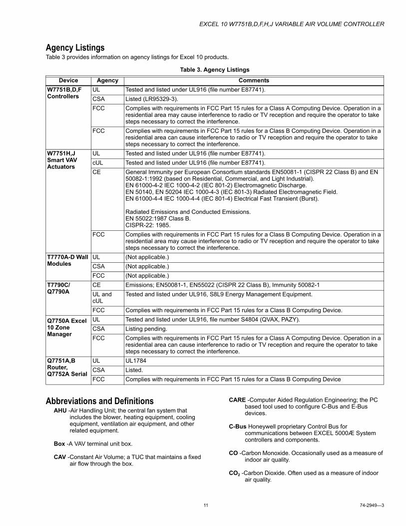
Agency ListingsTable 3 provides information on agency listings for Excel 10 products.
Abbreviations and DefinitionsAHU -Air Handling Unit; the central fan system that
includes the blower, heating equipment, cooling equipment, ventilation air equipment, and other related equipment.
Box -A VAV terminal unit box.
CAV -Constant Air Volume; a TUC that maintains a fixed air flow through the box.
CARE -Computer Aided Regulation Engineering; the PC based tool used to configure C-Bus and E-Bus devices.
C-Bus Honeywell proprietary Control Bus for communications between EXCEL 5000Æ System controllers and components.
CO -Carbon Monoxide. Occasionally used as a measure of indoor air quality.
CO2 -Carbon Dioxide. Often used as a measure of indoor air quality.
Table 3. Agency Listings
Device Agency CommentsW7751B,D,F Controllers
UL Tested and listed under UL916 (file number E87741).CSA Listed (LR95329-3).FCC Complies with requirements in FCC Part 15 rules for a Class A Computing Device. Operation in a
residential area may cause interference to radio or TV reception and require the operator to take steps necessary to correct the interference.
FCC Complies with requirements in FCC Part 15 rules for a Class B Computing Device. Operation in a residential area can cause interference to radio or TV reception and require the operator to take steps necessary to correct the interference.
W7751H,J Smart VAV Actuators
UL Tested and listed under UL916 (file number E87741).cUL Tested and listed under UL916 (file number E87741).CE General Immunity per European Consortium standards EN50081-1 (CISPR 22 Class B) and EN
50082-1:1992 (based on Residential, Commercial, and Light Industrial).EN 61000-4-2 IEC 1000-4-2 (IEC 801-2) Electromagnetic Discharge.EN 50140, EN 50204 IEC 1000-4-3 (IEC 801-3) Radiated Electromagnetic Field.EN 61000-4-4 IEC 1000-4-4 (IEC 801-4) Electrical Fast Transient (Burst).
Radiated Emissions and Conducted Emissions.EN 55022:1987 Class B.CISPR-22: 1985.
FCC Complies with requirements in FCC Part 15 rules for a Class B Computing Device. Operation in a residential area may cause interference to radio or TV reception and require the operator to take steps necessary to correct the interference.
T7770A-D Wall Modules
UL (Not applicable.)CSA (Not applicable.)FCC (Not applicable.)
T7790C/Q7790A
CE Emissions; EN50081-1, EN55022 (CISPR 22 Class B), Immunity 50082-1UL and cUL
Tested and listed under UL916, S8L9 Energy Management Equipment.
FCC Complies with requirements in FCC Part 15 rules for a Class B Computing Device.
Q7750A Excel 10 Zone Manager
UL Tested and listed under UL916, file number S4804 (QVAX, PAZY).CSA Listing pending.FCC Complies with requirements in FCC Part 15 rules for a Class A Computing Device. Operation in a
residential area can cause interference to radio or TV reception and require the operator to take steps necessary to correct the interference.
Q7751A,B Router, Q7752A Serial
UL UL1784CSA Listed.FCC Complies with requirements in FCC Part 15 rules for a Class B Computing Device
EXCEL 10 W7751B,D,F,H,J VARIABLE AIR VOLUME CONTROLLER
74-2949—3 12
CPU -Central Processing Unit; an EXCEL 5000Æ
cUL -Underwriters Laboratories Canada.
CVAHU -Constant Volume AHU; refers to a type of air handler with a single-speed fan that provides a constant amount of supply air to the space it serves.
DDF -Delta Degrees Fahrenheit.
DDWM -Digital Display Wall Module.
D/X -Direct Expansion; refers to a type of mechanical cooling where refrigerant is (expanded) to its cold state, within a heat-exchanging coil that is mounted in the air stream supplied to the conditioned space.
Echelon® - The company that developed the LON® bus and the Neuron® chips used to communicate on the LONWORKS Bus.
Economizer - Refers to the mixed-air dampers that regulate the quantity of outdoor air that enters the building. In cool outdoor conditions, fresh air can be used to supplement the mechanical cooling equipment. Because this action saves energy, the dampers are often referred to as economizer dampers.
E-Link -Refers to the Q7750A Zone Manager. This name is used in internal software and in CARE software.
EMI -Electromagnetic Interference; electrical noise that can cause problems with communications signals.
EMS -Energy Management System; refers to the controllers and algorithms responsible for calculating optimum operational parameters for maximum energy savings in the building.
EEPROM - Electrically Erasable Programmable Read Only Memory; the variable storage area for saving user setpoint values and factory calibration information.
EPROM - Erasable Programmable Read Only Memory; the firmware that contains the control algorithms for the Excel 10 Controller.
Excel 10 Zone Manager -A controller that is used to interface between the C-Bus and the E-Bus. The Excel 10 Zone Manager also has the functionality of an Excel 100 Controller, but has no physical I/O points.
NOTE: The Q7750A Zone Manager can be referred to as E-Link in the internal software, CARE.
Firmware - Software stored in a nonvolatile memory medium such as an EPROM.
Floating Control - Refers to Series 60 Modulating Control of a valve or damper. Floating Control utilizes one digital output to pulse the actuator open, and another digital output to pulse it closed.
IAQ -Indoor Air Quality. Refers to the quality of the air in the conditioned space, as it relates to occupant health and comfort.
I/O -Input/Output; the physical sensors and actuators connected to a controller.
I x R -I times R or current times resistance; refers to Ohm’s Law: V = I x R.
K -Degrees Kelvin.
Level IV - Refers to a classification of digital communication wire. Formerly known as UL Level IV, but not equivalent to Category IV cable. If there is any question about wire compatibility, use Honeywell-approved cables (see Step 5 Order Equipment section).
LONWORKS Bus (E-Bus) -Honeywell implementation of Echelon® LONWORKS® network for communication among Excel 10 Controllers.
LONWORKS® Bus Segment - One LONWORKS Bus section containing no more than 60 Excel 10s. Two segments can be joined together using a router.
NEC -National Electrical Code; the body of standards for safe field-wiring practices.
NEMA -National Electrical Manufacturers Association; the standards developed by an organization of companies for safe field wiring practices.
Node - A Communications Connection on a network; an Excel 10 Controller is one node on the LONWORKS Bus network.
NV -Network Variable; an Excel 10 parameter that can be viewed or modified over the LONWORKS Bus network.
OEM -Original Equipment Manufacturer; the company that builds the VAV boxes.
PC -An IBM compatible Personal Computer with 386 or higher processor and capable of running Microsoft® Windows® 95 or 98
Pot -Potentiometer. A variable resistance electronic component located on the T7770B,C Wall Module; used to allow user-adjusted setpoints to be input into the Excel 10 Controller.
PWM -Pulse Width Modulated output; allows analog modulating control of equipment using a digital output on the controller.
RTD -Resistance Temperature Detector; refers to a type of temperature sensor whose resistance output changes according to the temperature change of the sensing element.
Subnet - LONWORKS Bus segment.
TOD -Time-Of-Day; the scheduling of Occupied and Unoccupied times of operation.
EXCEL 10 W7751B,D,F,H,J VARIABLE AIR VOLUME CONTROLLER
13 74-2949—3
TCU -Terminal Control Unit; industry can refer to VAV box controllers such as the Excel 10 VAV Controller as TCUs.
TUC -Terminal Unit Controller; industry can refer to VAV box controllers such as the Excel 10 VAV Controller as TUCs.
VA -Volt Amperes; a measure of electrical power output or consumption as applies to an ac device.
Vac -Voltage alternating current; ac voltage rather than dc voltage.
VAV -Variable Air Volume; refers to either a type of air distribution system, or to the W7751 Excel 10 VAV Box Controller that controls a single zone in a variable air volume delivery system.
VOC -Volatile Organic Compound; refers to a class of common pollutants sometimes found in buildings. Sources include out-gassing of construction materials, production-line by-products, and general cleaning solvents. A VOC is occasionally used as a measure of indoor air quality.
W7751 - The model number of the Excel 10 VAV Box Controllers (also see VAV).
Wall Module - The Space Temperature Sensor and other optional controller inputs are contained in the T7770.
XBS -Excel Building Supervisor; a PC based tool for monitoring and changing parameters in C-Bus devices.
Zone Control Definitions
Variable Air Volume ATUsVariable air volume (VAV) ATUs are commonly called VAV boxes. Each VAV box has a controller that controls the temperature of a room or zone by modulating a damper in the VAV box to vary the amount of conditioned air supplied to the zone rather than changing the temperature of the conditioned air. They are used in larger buildings that have many zones along with a central air handling fan that supplies conditioned air via a pressurized main air duct system. The central air handling fan has a separate equipment controller that controls discharge air temperature, humidity, and supply duct static pressure.
Air Terminal Unit ControlAir terminal units (ATUs) regulate the amount of conditioned air delivered to satisfy the temperature requirements of a room or space. ATUs are classified by air handling system design and are available in several configurations. ATUs may be of variable air volume or constant volume design, and may be used in single-duct or dual-duct air handling systems. ATU controls can be as basic as a room thermostat controlling a damper or a more complex direct digital controller operating a damper, a terminal fan and enabling a reheat coil. In all cases, each ATU has a controller that is used to control the environment of the room or space.
Pressure-Dependent/-Independent ControlStatic pressure variations in an air handling system can affect terminal unit operation. Pressure-dependent terminal units are affected by changing duct static pressures because their damper position is determined by space temperature only. They may have mechanical or electric minimum and maximum air flow limits. Pressure-independent terminal units can automatically adjust to duct pressure changes because they contain air flow sensors and the controllers compensate for pressure changes in the main air distribution system. The damper position in pressure independent terminal units is determined by both space temperature and air flow volume.
Variable Air Volume ATUs (VAV)Variable air volume (VAV) ATUs are commonly called VAV boxes. Each VAV box has a controller that controls the temperature of a room or zone by modulating a damper in the VAV box to vary the amount of conditioned air supplied to the zone rather than changing the temperature of the conditioned air. They are used in larger buildings that have many zones along with a central air handling Unit (AHU) that supplies conditioned air via a pressurized main air duct system.
Single Duct Variable Air Volume (VAV) SystemsSingle duct VAV systems are used in over 80 percent of the VAV applications and employ one main supply air duct from the central air handling system. The air handling unit supplies cool air virtually one hundred percent of the time, with the only exception being a morning warm-up cycle that is used in buildings that are not continuously occupied, that temporarily raises the discharge air temperature of the central air handling system to quickly warm the building from its unoccupied zone temperatures to the occupied zone temperatures. Since the central air handling system is usually supplying cool air, single or multiple electric reheat coils or a modulating hot water (hydronic) reheat coil are often added in the VAV box discharge air duct to reheat the cool air when the zone becomes too cold. VAV boxes with reheat coils typically have a series or parallel fan in the VAV box to ensure air flow across the coil in the heating mode.
Pressure-Dependent Throttling VAV BoxesPressure dependent throttling VAV boxes are the simplest and least expensive ATU. A controller modulates a damper actuator according to the temperature in the zone. The pressure dependent VAV box usually has minimum and/or maximum damper position setpoint stops in the controller for limiting air volume. Because the unit is pressure dependent, the volume of air distributed to the zone at any given space temperature varies with the supply duct static pressure at the inlet of the VAV box. Maintaining a stable duct static pressure is important for proper operation and proper setting of the minimum damper position setpoint stop is essential for adequate circulation. When reheat coils and/or finned tube radiation are used the controller will set the damper position at a minimum position during the heating mode to ensure some air flow into the space and optimize heat transfer from the reheat coil. Pressure dependent VAV boxes are used in smaller buildings or in areas of larger buildings where the supply duct static pressure is low and stable.
EXCEL 10 W7751B,D,F,H,J VARIABLE AIR VOLUME CONTROLLER
74-2949—3 14
Pressure-Independent VAV BoxesPressure-independent or variable constant-volume VAV boxes are essentially air flow control devices that deliver a constant volume of air to a conditioned space at a given temperature despite a varying supply duct static pressure. An air flow sensor in the inlet of the VAV box is used to measure the volume of air and the VAV box controller resets the air flow volume setpoint as the thermal load changes in the space. Therefore, a pressure independent VAV box controller provides two control sequences; zone temperature control and terminal unit air flow control. The controller usually has a minimum air flow setpoint to maintain air flow at light load conditions and a maximum air flow setpoint to limit the air flow to meet the design conditions for the zone. A single zone sensor can be used to control multiple VAV boxes with differing volume ratings. When reheat coils and/or finned tube radiation are used with this unit the controller will lower the air flow setpoint during the heating mode to ensure air flow into the room and optimize heat transfer from the reheat coil. Pressure independent VAV boxes are used in buildings with larger air handling systems that have constant duct static pressure fluctuations due to the large number of zones.
Series Fan Powered VAV BoxesSeries Fan-powered VAV boxes are similar to pressure dependent and/or pressure independent VAV boxes, except they include an integral fan in series with the VAV box discharge duct that recirculates space air at constant volume and enhances the air distribution in the zone. Primary air is modulated by the VAV box damper to meet space demand for cooling and as primary air modulates down, more plenum air is drawn in by the fan to maintain a constant discharge volume to the zone. Typically the series fan is on continuously during occupied hours, or it can be programmed to be activated as primary air decreases to ensure adequate air circulation. In addition to enhancing air distribution, the units serving the perimeter area of a building usually include a reheat coil that is sequenced with the primary air damper to supply heat when required. When the primary air system is not operating (nighttime or unoccupied control mode), the night operating mode of the controller enables the fan and the reheat coil to maintain the lower unoccupied temperature setpoint in the space. Series Fan Powered VAV boxes can be pressure independent or pressure dependent.
Parallel Fan Powered VAV BoxesParallel Fan Powered VAV boxes or Bypass Fan Induction Terminal Units are similar to Series Fan-powered VAV terminal units, except the fan is located in the return plenum and does not run continuously during occupied hours. When the zone temperature is low and the need for primary air decreases, the controller modulates the primary air damper to a minimum and enables the fan, which recirculates warm air from the return plenum into the zone acting as the first stage of reheat. If a reheat coil is used the fan is cycled on when the reheat coil is enabled. As the space warms, the reheat valve closes and the fan cycles off as the primary air damper opens to allow delivery of conditioned air from the air handling system. When heating is required in the unoccupied mode, the fan at the central air handling system remains off, the VAV box fan and the reheat coil are enabled and the zone is heated to a reduced night setback temperature using air from the return air plenum. Parallel Fan Powered VAV boxes can be pressure independent or pressure dependent.
Induction VAV BoxesInduction VAV boxes use induced return air as the reheat medium which means no parallel fan is present in the VAV box. Induction VAV boxes are usually installed above the ceiling and draw return air from the plenum created by a false ceiling. The VAV box controller uses an air flow sensor for controlling air flow and a room sensor for controlling room temperature similar to pressure independent VAV boxes. The volume of air coming through the primary damper is controlled by positioning both dampers simultaneously so that as the primary air damper closes, the return air damper opens. Return air is thus drawn into the unit and recirculated into the space. Like pressure independent VAV boxes the controller resets the air flow setpoint of the controller as the thermal load changes in the conditioned space. For extremely cold design conditions, a reheat coil can be added.
The induction VAV ATU maintains satisfactory air motion at lower loads than a throttling VAV box can, however, the wide use of Parallel Fan Powered VAV boxes has now limited the use of Induction VAV boxes.
Single-Duct Constant Volume Zone Reheat Air Terminal UnitsSingle-Duct Constant Volume Zone Reheat Systems are used in low static pressure systems and have a heating coil (hot water, steam, or electric) in the branch supply duct to each zone. The central air-handling unit supplies constant temperature air and a manual balancing damper in each zone is set in a fixed position to determine the amount of air delivered to that zone. The volume of air delivered to each zone will change as the static pressure of the supply duct changes, however, in low static pressure systems the changes in the supply duct static pressure are small and do not have a dramatic effect on the amount air delivered to the zone. The control strategy used in single zone reheat systems is simple and involves activating electric heat or positioning a valve in conjunction to the zone temperature. In most cases this is accomplished using a simple space thermostat. However, direct digital controllers can be used in these cases to control multiple zone valve positions the reheat coil valve (or electric heating elements) as required to maintain space condition.
Dual Duct Air Handling SystemsIn a dual-duct air handling system, supply air is divided at the central fan and hot air and cold air flow through separate ducts to the perimeter zones in the building. Dual-duct terminal units are essentially mixing boxes with two supply inlets and one discharge outlet. The air is allowed to mix in the mixing box section and is discharged out of a single duct into the zone. Since a source of heating is available reheat coils are not used in the zone. Basic dual-duct mixing systems were not economical because supply air was cooled and heated year round and modern energy codes prohibited their use in many cities in the U.S. except in critical applications like hospitals, nursing homes, etc. However, with direct digital controllers and networked systems the individual zone data can be used to reset hot and cold duct temperatures as needed, allowing dual duct systems to be used more often in today’s applications. Dual duct systems are often used in conjunction with single duct systems in the same building.
EXCEL 10 W7751B,D,F,H,J VARIABLE AIR VOLUME CONTROLLER
15 74-2949—3
Variable Constant Volume (Zero Energy Band) Dual-Duct VAV BoxesVariable Constant Volume (Zero Energy Band) Dual-Duct VAV Boxes have inlet dampers (with individual damper actuators and air flow sensors) on the cooling and heating supply ducts. The air flow is pressure independent and the Dual Duct VAV Box controller uses the zone temperature to determine the required flow of hot and cold air from the respective ducts into the mixing box and resets the hot duct and cold duct air flow setpoints in sequence as space load changes. The Zero Energy Band (ZEB) is an energy conservation technique that allows temperatures to float between programmable settings to prevent the consumption of heating or cooling energy while the temperature is in this range. As space temperature rises to approach the controller setpoint, the hot air flow volume drops to zero. If space temperature continues to rise through the ZEB, the output signal from the controller modulates the cold-air damper open. The controller maintains adjustable minimum flows for ventilation, with no overlap of damper operations, during the ZEB when neither heating nor cooling is required. For example, if a zone had a setpoint of 74 degrees and a zero energy band of 2 degrees then the zone temperature would be allowed to float between 73 degrees and 75 degrees before the controller would use hot air to heat the zone or cool air to cool the zone. When the ZEB technique is properly used the comfort of the occupants is not sacrificed in the process of saving energy.
Dual Duct Constant Volume SystemsDUAL-DUCT MIXING BOX TERMINAL UNITSDual-duct mixing box terminal units generally apply to low-static pressure systems that require large amounts of ventilation. The warm duct damper and the cool duct damper are linked to operate in reverse of each other from a single damper actuator. The controller positions the mixing dampers through a damper actuator to mix warm and cool supply air to maintain space condition. Discharge air quantity depends on the static pressure in each supply duct at that location.
DUAL-DUCT CONSTANT VOLUME MIXING BOX TERMINAL UNITSDual-duct constant volume mixing box terminal units are typically used on high-static-pressure systems where the air flow quantity to each space is critical. The units are the same as those described in the previous paragraph, except that they include either an integral mechanical constant volume regulator or an air flow constant volume control furnished by the unit manufacturer to change the damper position to maintain a constant air flow volume with changes in duct static pressure.
Variable Volume/Variable Temperature (VVT)VVT systems are also called commercial zoning systems and use a constant volume air supply (roof top unit, heat pump, small air handler) with heating, cooling and economizer functions and vary the flow rates and supply-air temperature into smaller, damper-controlled zones through a single duct distribution system. Each zone damper is modulated based on space temperature. However, damper control is based only on zone temperature and there is no flow control at the zone level as there is in a pressure independent variable air volume (VAV) system. Typically, the zone damper is modulated using an analog signal, providing excellent zone temperature control. A method of providing feedback of zone demand is
provided which allows a controller at the rooftop to provide the minimum required amounts of heating and cooling (using economizer when acceptable) based on zone demand.
Because a number of zone dampers can possibly be closed, there needs to be a way to relieve pressure in the supply duct. A bypass damper is normally added in a duct between the supply and return ducts to relieve pressure. The pressure relief damper is normally controlled by sensing supply duct pressure and opening to vent supply air directly to return. This is one difference between a commercial zoning system and true VAV. A true VAV air handler actually varies air volume through the blower.
VVT makes it possible to operate a single-zone heating/cooling unit with multiple-zones and is often used in smaller buildings. Small buildings are not appropriate for VAV systems because the heating and cooling loads are not large enough for a VAV system to operate properly. VVT systems also cost less than VAV systems due to the use of constant volume packaged units, lower pressure ductwork, and they often do not require expensive perimeter heat. The main difference between VAV and VVT is the fact that VAV systems vary the amount of air entering a zone and not the temperature, where a VVT system varies both the amount of air and the temperature of the air entering the zone.
Single Zone Rooftop Air Handling Unit Control (CVAHU)Single-zone systems use a Constant Volume Air-Handling Unit (CVAHU) which are usually factory-packaged units mounted on the rooftop of the building, however, single zone air handling units can also be located in a mechanical room of buildings. Single zone units are used in smaller buildings, buildings that have a uniform heating/cooling load in large open zones, or in zones that have special comfort requirements that are different from other areas of the building. The building must also have the space available for the associated air handling equipment. Typical installations include; office/warehouse buildings, large open buildings such as supermarkets, restaurants, and ballrooms and lobbies of large buildings and hotels. Since single zone units are associated with only one zone, many single zone air handling units can be installed in a building. Fan volume control, as found in Variable Air Volume systems is not required, because fan volume and duct static pressure are set by the manufacturer to meet the design needs of the zone.
TEMPERATURE AND VENTILATION CONTROLA single space controller or thermostat controls the heating coil, ventilation dampers, and cooling coil in sequence as thermal load varies in the conditioned space. On rooftop mounted units the heating coils are typically electric and the cooling is by a self contained air-conditioning system using direct expansion cooling coils. However, single zone air handling systems that are located in a mechanical room of a building often employ hot water (hydronic) heating coils and use chilled water coils for cooling. The ventilation dampers (Outdoor air, Return air, and Exhaust air) are controlled to use outdoor air for the first-stage cooling when the conditions are appropriate. When outdoor air temperature or heat content (enthalpy) rises to the point that it can no longer be used for cooling, an outdoor air limit control overrides the signal to the ventilation dampers and moves them to the minimum ventilation position, as determined by the minimum positioning switch or the minimum position setpoint in the controller.
EXCEL 10 W7751B,D,F,H,J VARIABLE AIR VOLUME CONTROLLER
74-2949—3 16
Indoor air quality control is also accomplished with the Single Zone controller using sensors and control strategies that increase the minimum position of the outdoor air damper to allow more fresh air into the building when the indoor air quality is poor. A zero energy band often separates the heating and cooling control ranges, thus saving energy.
Unitary Equipment ControlUnitary equipment includes natural convection units, radiant panels, unit heaters, unit ventilators, fan coil units, and heat pumps. Unitary equipment does not require a central fan. Depending on design, unitary equipment may perform one or all of the functions of HVAC - ventilation, filtration, heating, cooling, humidification and distribution. Unitary equipment frequently requires a distribution system for steam or hot and/or chilled water.
Control of unitary equipment varies with system design. Typically, a room thermostat provides a signal to a controlled device to regulate the unit. The unit may use a day/night thermostat for operation at lower setpoints during unoccupied hours. If the unit has a fan, a time clock may be used to turn the fan off at night, and a night thermostat may be used to control the temperature within night limits. When DDC control is used all of the thermostat and time clock functionality is contained in the controller.
CommunicationsRefer to LONWORKS Bus Wiring Guidelines form, 74-2865 for complete description of network topology rules.
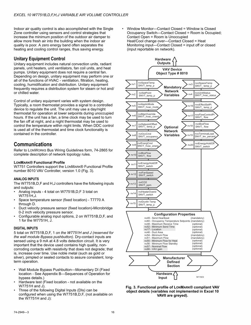
LONMARK® Functional ProfileW7751 Controllers support the LONMARK® Functional Profile number 8010 VAV Controller, version 1.0 (Fig. 3).
ANALOG INPUTSThe W7751B,D,F and H,J controllers have the following inputs and outputs:• Analog inputs - 4 total on W7751B,D,F 3 total on
W7751H,J.• Space temperature sensor (fixed location) - T7770 A
through D. • Duct velocity pressure sensor (fixed location)-Microbridge
0-2 inch velocity pressure sensor. • Configurable analog input options, 2 on W7751B,D,F, and
1 for the W7751H, J.
DIGITAL INPUTS5 total on W7751B,D,F, 1 on the W7751H and J (reserved for the wall module Bypass pushbutton). Dry-contact inputs are sensed using a 9 mA at 4.8 volts detection circuit. It is very important that the device used contains high quality, non-corroding contacts with resistivity that does not degrade; that is, increase over time. Use noble metal (such as gold or silver), pimpled or sealed contacts to assure consistent, long-term operation.
• Wall Module Bypass Pushbutton—Momentary DI (Fixed location - See Appendix B—Sequences of Operation for bypass details.)
• Hardware test (Fixed location - not available on the W7751H and J).
• Three of the following Digital Inputs (DIs) can be configured when using the W7751B,D,F, (not available on the W7751H and J):
• Window Monitor—Contact Closed = Window is Closed Occupancy Switch—Contact Closed = Room is Occupied; Contact Open = Room is Unoccupied Heat/Cool change over—Contact Closed = Heat Monitoring input—Contact Closed = input off or closed (input reportable on network).
Fig. 3. Functional profile of LONMARK® compliant VAV object details (variables not implemented in Excel 10
VAVII are greyed).
HardwareOutputs
VAV Device Object Type # 8010
Mandatory NetworkVariables
ManufacturerDefinedSection
OptionalNetworkVariables
nv9nviEnergCmdSNVT_hvac_energ
nv8
nv7nviSetpointOffsetSNVT_ temp_p
nv6nviManOverride
nviOccCmdSNVT_occupancy
nv5nviApplicModeSNVT_hvac_mode
SNVT_hvac_overid
nv19nvoTerminalLoadSNVT_lev_percent
nv18nvoBoxFlow
nv17 nvoFlowControlPtSNVT_ flow
SNVT_ flow
nv16nvoEffectSetPtSNVT_ temp_p
nv2nviSetPointSNVT_temp_p
nv1nviSpaceTempSNVT_temp_p
nv4nvoUnitStatusSNVT_hvac_status
nv3nvoSpaceTempSNVT_ temp_p
nv10nviBoxFlowSNVT_ flow
nv11nviEnergyHoldOff
SNVT_switch
HardwareInput
nc46 - Duct Area
nc49 - Send Heartbeat (mandatory)
nc60 - Occupancy Temperature Setpoints
(optional)nc48 - Maximum Receive Time
nc54 - Minimum Flow
nc56 - Minimum Flow Standby
(optional)
(mandatory)
(mandatory)nc51 - Maximum Flow (mandatory)
(optional)(optional)
(optional)(optional)(optional)
(optional)
Configuration Properties
nv12
nv13
nv14
nv15
nviFanSpeed
nviCO2
nviHeaterOverid
nviDuctIn Temp
nv20
M11823
SNVT_switch
SNVT_ppm
SNVT_switch
SNVT_temp_p
nviEnergyHoldOff
SNVT_switch
nc66 - VAV gainnc57 - Nominal Flow
nc52 - Minimum Send Timenc17 - Location
nc55 - Minimum Flow for Heat
EXCEL 10 W7751B,D,F,H,J VARIABLE AIR VOLUME CONTROLLER
17 74-2949—3
DIGITAL OUTPUTS8 total on W7751B,D,F (configurable locations), 4 total on W7751H and J (2 fixed position damper outputs and 2 configurable outputs). Configurable digital output options.
— Floating damper open (fixed location on W7751H,J)— Floating damper closed (fixed location on W7751H,J)— Reheat types
• Reheat (floating) valve open• Reheat (floating) valve closed• PWM• Stage 1• Stage 2 or Three stage binary control• Stage 3 (not available on W7751H,J)• Peripheral Heating types• Peripheral heat (floating) valve open• Peripheral heat (floating) valve closed• PWM• Stage 1
— Fan (Series or Parallel)• On/Off• PWM
— Auxiliary (On when occupied, Off when unoccupied or Standby)• Normal (On/Off)• Pulsed (requires two pairs open and closed)
— Network (up to 2 outputs commanded from the network)• Normal (On/Off)• Pulsed (requires two pairs open and closed)
Triac Outputs on the W7751B,D,F Model:Power ratings: 20 Vac to 30 Vac at 25 mA MIN to 1.0A
MAX current for any voltage.(For W7751H,J a minimum of 25 mA at 20 Vac and a
maximum of 400 mA at 30 Vac.)
IMPORTANTWhen any device is energized by a Triac, the device must be able to sink a minimum of 25 mA.
NOTE: Triacs sink current to the 24 Vac common (terminals 10 on the W7751B model, or terminals 2 and 4 on the W7751D,F models, or terminal 2 on the W7751H,J models). The controller and all Triac loads must be wired to the same 24 Vac source.
IMPORTANTIf non-Honeywell motors, actuators, or transducers are to be used with Excel 10 Controllers, Triac compatibility must be verified (see previous NOTE).
Configurations
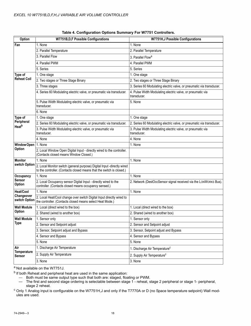
GeneralTable 4 lists the general mechanical equipment options available with the W7751 VAV Box Controller. See Table 1 for Excel 10 VAV Box Controller capabilities. All VAV boxes are assumed to have an air flow pickup for connecting to the Microbridge flow through pressure sensor on the Excel 10 VAV Controller except for the W7751J. Also, each box must have a flow-regulating damper that is controlled by a Series 60 (floating) type actuator such as the Honeywell ML6161 or a PWM type actuator.
IMPORTANT• The Excel 10 VAV Controller is designed to work with
Series 60 (floating) Damper Actuators that have a full stroke damper actuator time between 20 and 600 seconds (0.333 to 10 minutes) or PWM Damper Actuators that have a minimum time (zero percent) of 0.1 second and a maximum overall time of 600 seconds (0.1 second to 10 minutes).
• The W7751H,J Excel 10 VAV Controller is designed to work only with the Series 60 (floating) damper actuator (ML6161B) that has a full stroke damper actuator time of 90 seconds.
EXCEL 10 W7751B,D,F,H,J VARIABLE AIR VOLUME CONTROLLER
74-2949—3 18
a Not available on the W7751J.b If both Reheat and peripheral heat are used in the same application:
— Both must be same output type such that both are: staged, floating or PWM.— The first and second stage ordering is selectable between stage 1 - reheat, stage 2 peripheral or stage 1- peripheral,
stage 2 reheat.c Only 1 Analog input is configurable on the W7751H,J and only if the T7770A or D (no Space temperature setpoint) Wall mod-
ules are used.
Table 4. Configuration Options Summary For W7751 Controllers.
Option W7751B,D,F Possible Configurations W7751H,J Possible ConfigurationsFan 1. None 1. None
2. Parallel Temperature 2. Parallel Temperature3. Parallel Flow 3. Parallel Flowa
4. Parallel PWM 4. Parallel PWM5. Series 5. Series
Type of Reheat Coil
1. One stage 1. One stage2. Two stages or Three Stage Binary 2. Two stages or Three Stage Binary3. Three stages 3. Series 60 Modulating electric valve, or pneumatic via transducer.4. Series 60 Modulating electric valve, or pneumatic via transducer. 4. Pulse Width Modulating electric valve, or pneumatic via
transducer.5. Pulse Width Modulating electric valve, or pneumatic via transducer.
5. None
6. NoneType of Peripheral Heatb
1. One stage 1. One stage2. Series 60 Modulating electric valve, or pneumatic via transducer. 2. Series 60 Modulating electric valve, or pneumatic via transducer.3. Pulse Width Modulating electric valve, or pneumatic via transducer.
3. Pulse Width Modulating electric valve, or pneumatic via transducer.
4. None 4. NoneWindow Open Option
1. None 1. None2. Local Window Open Digital Input - directly wired to the controller. (Contacts closed means Window Closed.)
Monitor switch Option
1. None 1. None2. Local Monitor switch (general purpose) Digital Input -directly wired to the controller. (Contacts closed means that the switch is closed.)
Occupancy Sensor Option
1. None 1. None2. Local Occupancy sensor Digital Input - directly wired to the controller. (Contacts closed means occupancy sensed.)
2. Network (DestOccSensor signal received via the LONWORKS Bus).
Heat/Cool Changeover switch Option
1. None 1. None2. Local Heat/Cool change over switch Digital Input directly wired to the controller. (Contacts closed means select Heat Mode.)
Wall Module Option
1. Local (direct wired to the box) 1. Local (direct wired to the box)2. Shared (wired to another box) 2. Shared (wired to another box)
Wall Module Type
1. Sensor only 1. Sensor only2. Sensor and Setpoint adjust 2. Sensor and Setpoint adjust3. Sensor, Setpoint adjust and Bypass 3. Sensor, Setpoint adjust and Bypass4. Sensor and Bypass 4. Sensor and Bypass5. None 5. None
Air Temperature Sensor
1. Discharge Air Temperature 1. Discharge Air Temperaturec
2. Supply Air Temperature 2. Supply Air Temperaturec
3. None 3. None
EXCEL 10 W7751B,D,F,H,J VARIABLE AIR VOLUME CONTROLLER
19 74-2949—3
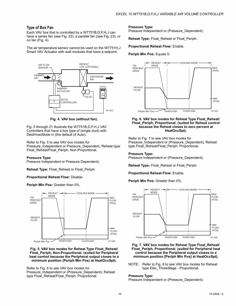
Type of Box FanEach VAV box that is controlled by a W7751B,D,F,H,J can have a series fan (see Fig. 22), a parallel fan (see Fig. 23), or no fan (Fig. 4).
The air temperature sensor cannot be used on the W7751H,J Smart VAV Actuator with wall modules that have a setpoint.
Fig. 4. VAV box (without fan).
Fig. 5 through 21 illustrate the W7751B,D,F,H,J VAV Controllers that have a box type of (single duct) with DestHvacMode in (the default of Auto).
Refer to Fig. 5 to see VAV box modes for Pressure_Independent or Pressure_Dependent, Reheat type Float_Reheat/Float_Periph, Non-Proportional.
Pressure Type:Pressure Independent or Pressure Dependent).
Reheat Type: Float_Reheat or Float_Periph.
Proportional Reheat Flow: Disable.
Periph Min Pos: Greater than 0%.
Fig. 5. VAV box modes for Reheat Type Float_Reheat/Float_Periph, Non-Proportional. (suited for Peripheral heat control because the Peripheral output closes to a
minimum position (Periph Min Pos) at HeatOccSpt).
Refer to Fig. 6 to see VAV box modes for Pressure_Independent or (Pressure_Dependent), Reheat type Float_Reheat/Float_Periph, Proportional.
Pressure Type:Pressure Independent or (Pressure_Dependent).
Reheat Type: Float_Reheat or Float_Periph.
Proportional Reheat Flow: Enable.
Periph Min Pos: Equals 0.
Fig. 6. VAV box modes for Reheat Type Float_Reheat/Float_Periph, Proportional. (suited for Reheat control
because the Reheat closes to zero percent at HeatOccSpt).
Refer to Fig. 7 to see VAV box modes for Pressure_Independent or (Pressure_Dependent), Reheat type Float_Reheat/Float_Periph, Proportional.
Pressure Type:Pressure Independent or (Pressure_Dependent).
Reheat Type: Float_Reheat or Float_Periph.
Proportional Reheat Flow: Enable.
Periph Min Pos: Greater than 0%.
Fig. 7. VAV box modes for Reheat Type Float_Reheat/Float_Periph, Proportional. (suited for Peripheral heat
control because the Peripheral output closes to a minimum position [Periph Min Pos] at HeatOccSpt).
NOTE: Refer to Fig. 8 to see VAV box modes for Reheat type Elec_ThreeStage - Proportional.
Pressure Type:Pressure Independent or (Pressure_Dependent).
M11824
AIR FLOWSENSOR
PRIMARYAIR
DAMPER ACTUATOR
REHEATCOIL (OPTIONAL)
DISCHARGEAIR
VALVE
T7770
W7751CONTROLLER
100PERCENTOPEN
REHEATFLOW
M11826
REHEAT MODE
COOLING MODE
MAXFLOW (POS)
MINFLOW (POS)
HeatOccSpt CoolOccSptPeriph Min Pos
REHEATFLOW
MAX (POS)
MIN (POS)
M11827
100PERCENTOPEN
HeatOccSpt CoolOccSptPeriph Min Pos
REHEAT MODE
COOLING MODE
REHEATFLOW
M11828
100PERCENTOPEN
HeatOccSpt CoolOccSpt
REHEAT MODE
COOLING MODE
MAXFLOW (POS)
MINFLOW (POS)
Periph Min Pos
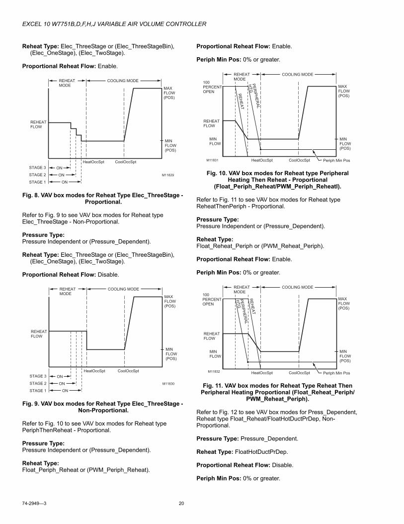
EXCEL 10 W7751B,D,F,H,J VARIABLE AIR VOLUME CONTROLLER
74-2949—3 20
Reheat Type: Elec_ThreeStage or (Elec_ThreeStageBin), (Elec_OneStage), (Elec_TwoStage).
Proportional Reheat Flow: Enable.
Fig. 8. VAV box modes for Reheat Type Elec_ThreeStage - Proportional.
Refer to Fig. 9 to see VAV box modes for Reheat type Elec_ThreeStage - Non-Proportional.
Pressure Type:Pressure Independent or (Pressure_Dependent).
Reheat Type: Elec_ThreeStage or (Elec_ThreeStageBin), (Elec_OneStage), (Elec_TwoStage).
Proportional Reheat Flow: Disable.
Fig. 9. VAV box modes for Reheat Type Elec_ThreeStage - Non-Proportional.
Refer to Fig. 10 to see VAV box modes for Reheat type PeriphThenReheat - Proportional.
Pressure Type:Pressure Independent or (Pressure_Dependent).
Reheat Type:Float_Periph_Reheat or (PWM_Periph_Reheat).
Proportional Reheat Flow: Enable.
Periph Min Pos: 0% or greater.
Fig. 10. VAV box modes for Reheat type Peripheral Heating Then Reheat - Proportional
(Float_Periph_Reheat/PWM_Periph_Reheatl).
Refer to Fig. 11 to see VAV box modes for Reheat type ReheatThenPeriph - Proportional.
Pressure Type:Pressure Independent or (Pressure_Dependent).
Reheat Type:Float_Reheat_Periph or (PWM_Reheat_Periph).
Proportional Reheat Flow: Enable.
Periph Min Pos: 0% or greater.
Fig. 11. VAV box modes for Reheat Type Reheat Then Peripheral Heating Proportional (Float_Reheat_Periph/
PWM_Reheat_Periph).
Refer to Fig. 12 to see VAV box modes for Press_Dependent, Reheat type Float_Reheat/FloatHotDuctPrDep, Non-Proportional.
Pressure Type: Pressure_Dependent.
Reheat Type: FloatHotDuctPrDep.
Proportional Reheat Flow: Disable.
Periph Min Pos: 0% or greater.
REHEATFLOW
M11829
ON
ON
ON
STAGE 3
STAGE 2
STAGE 1
HeatOccSpt CoolOccSpt
MAXFLOW (POS)
MINFLOW (POS)
REHEAT MODE
COOLING MODE
REHEATFLOW
M11830
ON
ON
ON
STAGE 3
STAGE 2
STAGE 1
HeatOccSpt CoolOccSpt
REHEAT MODE
COOLING MODE
MAXFLOW (POS)
MINFLOW (POS)
REHEATFLOW
MIN FLOW
M11831
PE
RIP
HE
RA
L
HT
G
RE
HE
AT
HeatOccSpt CoolOccSpt
100PERCENTOPEN
REHEAT MODE
COOLING MODE
MAXFLOW (POS)
MINFLOW (POS)
Periph Min Pos
REHEATFLOW
MIN FLOW
M11832
PE
RIP
HE
RA
L
HT
G
RE
HE
AT
100PERCENTOPEN
REHEAT MODE
COOLING MODE
HeatOccSpt CoolOccSpt Periph Min Pos
MAXFLOW (POS)
MINFLOW (POS)
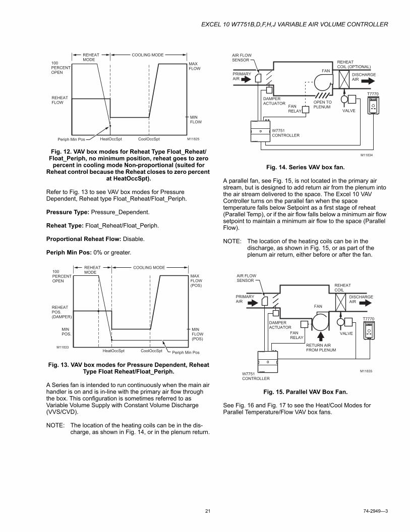
EXCEL 10 W7751B,D,F,H,J VARIABLE AIR VOLUME CONTROLLER
21 74-2949—3
Fig. 12. VAV box modes for Reheat Type Float_Reheat/Float_Periph, no minimum position, reheat goes to zero
percent in cooling mode Non-proportional (suited for Reheat control because the Reheat closes to zero percent
at HeatOccSpt).
Refer to Fig. 13 to see VAV box modes for Pressure Dependent, Reheat type Float_Reheat/Float_Periph.
Pressure Type: Pressure_Dependent.
Reheat Type: Float_Reheat/Float_Periph.
Proportional Reheat Flow: Disable.
Periph Min Pos: 0% or greater.
Fig. 13. VAV box modes for Pressure Dependent, Reheat Type Float Reheat/Float_Periph.
A Series fan is intended to run continuously when the main air handler is on and is in-line with the primary air flow through the box. This configuration is sometimes referred to as Variable Volume Supply with Constant Volume Discharge (VVS/CVD).
NOTE: The location of the heating coils can be in the dis-charge, as shown in Fig. 14, or in the plenum return.
Fig. 14. Series VAV box fan.
A parallel fan, see Fig. 15, is not located in the primary air stream, but is designed to add return air from the plenum into the air stream delivered to the space. The Excel 10 VAV Controller turns on the parallel fan when the space temperature falls below Setpoint as a first stage of reheat (Parallel Temp), or if the air flow falls below a minimum air flow setpoint to maintain a minimum air flow to the space (Parallel Flow).
NOTE: The location of the heating coils can be in the discharge, as shown in Fig. 15, or as part of the plenum air return, either before or after the fan.
Fig. 15. Parallel VAV Box Fan.
See Fig. 16 and Fig. 17 to see the Heat/Cool Modes for Parallel Temperature/Flow VAV box fans.
100PERCENTOPEN
REHEATFLOW
MAX FLOW
MIN FLOW
M11825HeatOccSpt CoolOccSpt
REHEAT MODE
COOLING MODE
Periph Min Pos
REHEATPOS.(DAMPER)
MIN POS.
M11833
REHEAT MODE
COOLING MODE
HeatOccSpt CoolOccSpt
100PERCENTOPEN
Periph Min Pos
MAXFLOW (POS)
MINFLOW (POS)
M11834
AIR FLOWSENSOR
PRIMARYAIR
DAMPER ACTUATOR
FAN RELAY
FAN
REHEATCOIL (OPTIONAL)
DISCHARGEAIR
VALVE
OPEN TO PLENUM
W7751CONTROLLER
T7770
AIR FLOWSENSOR
PRIMARYAIR
DAMPER ACTUATOR
FAN RELAY
FAN
REHEATCOIL
DISCHARGEAIR
VALVE
RETURN AIRFROM PLENUM
W7751CONTROLLER
T7770
M11835
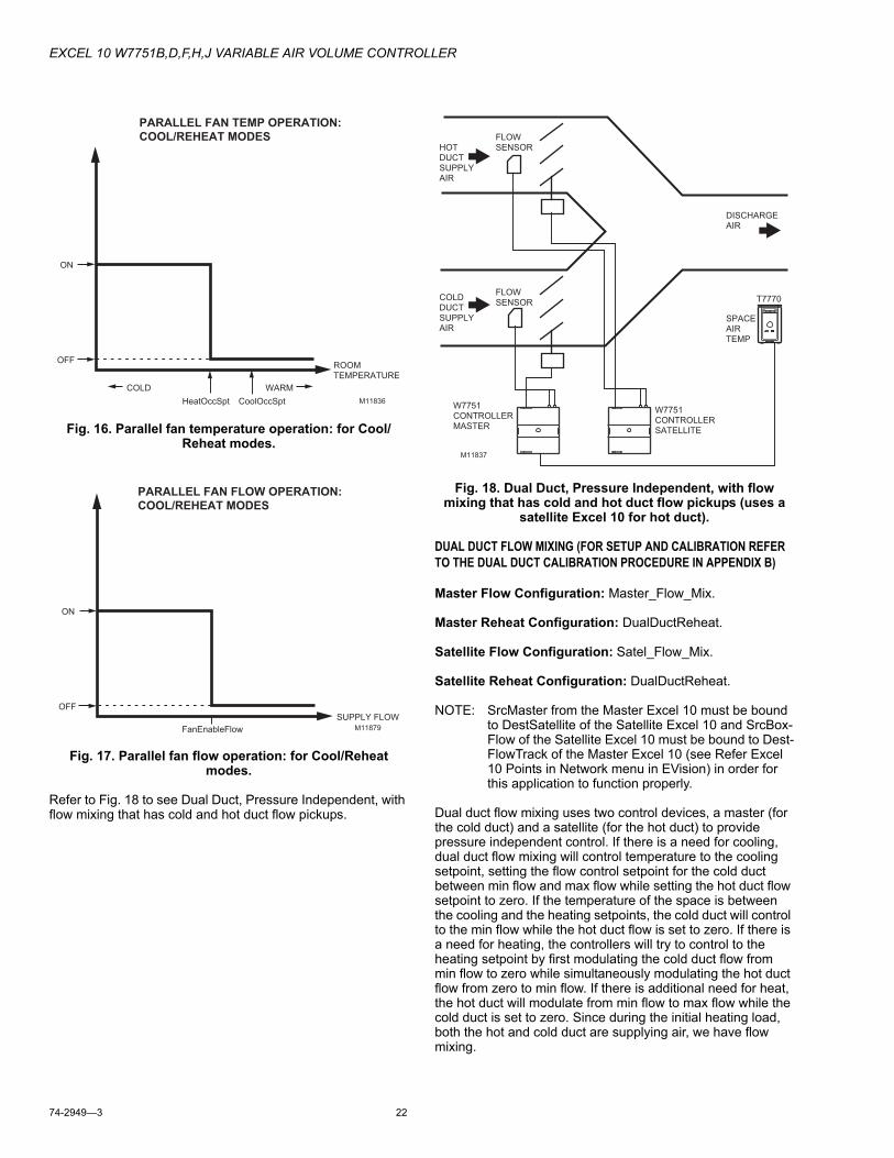
EXCEL 10 W7751B,D,F,H,J VARIABLE AIR VOLUME CONTROLLER
74-2949—3 22
Fig. 16. Parallel fan temperature operation: for Cool/Reheat modes.
Fig. 17. Parallel fan flow operation: for Cool/Reheat modes.
Refer to Fig. 18 to see Dual Duct, Pressure Independent, with flow mixing that has cold and hot duct flow pickups.
Fig. 18. Dual Duct, Pressure Independent, with flow mixing that has cold and hot duct flow pickups (uses a
satellite Excel 10 for hot duct).
DUAL DUCT FLOW MIXING (FOR SETUP AND CALIBRATION REFER TO THE DUAL DUCT CALIBRATION PROCEDURE IN APPENDIX B)
Master Flow Configuration: Master_Flow_Mix.
Master Reheat Configuration: DualDuctReheat.
Satellite Flow Configuration: Satel_Flow_Mix.
Satellite Reheat Configuration: DualDuctReheat.
NOTE: SrcMaster from the Master Excel 10 must be bound to DestSatellite of the Satellite Excel 10 and SrcBox-Flow of the Satellite Excel 10 must be bound to Dest-FlowTrack of the Master Excel 10 (see Refer Excel 10 Points in Network menu in EVision) in order for this application to function properly.
Dual duct flow mixing uses two control devices, a master (for the cold duct) and a satellite (for the hot duct) to provide pressure independent control. If there is a need for cooling, dual duct flow mixing will control temperature to the cooling setpoint, setting the flow control setpoint for the cold duct between min flow and max flow while setting the hot duct flow setpoint to zero. If the temperature of the space is between the cooling and the heating setpoints, the cold duct will control to the min flow while the hot duct flow is set to zero. If there is a need for heating, the controllers will try to control to the heating setpoint by first modulating the cold duct flow from min flow to zero while simultaneously modulating the hot duct flow from zero to min flow. If there is additional need for heat, the hot duct will modulate from min flow to max flow while the cold duct is set to zero. Since during the initial heating load, both the hot and cold duct are supplying air, we have flow mixing.
M11836
ROOMTEMPERATURE
COLD WARM
OFF
ON
PARALLEL FAN TEMP OPERATION:
COOL/REHEAT MODES
HeatOccSpt CoolOccSpt
M11879
SUPPLY FLOW
OFF
ON
PARALLEL FAN FLOW OPERATION:
COOL/REHEAT MODES
FanEnableFlow
T7770
HOTDUCTSUPPLYAIR
COLDDUCTSUPPLYAIR
DISCHARGE AIR
FLOWSENSOR
FLOWSENSOR
W7751CONTROLLERMASTER
SPACEAIRTEMP
W7751CONTROLLERSATELLITE
M11837
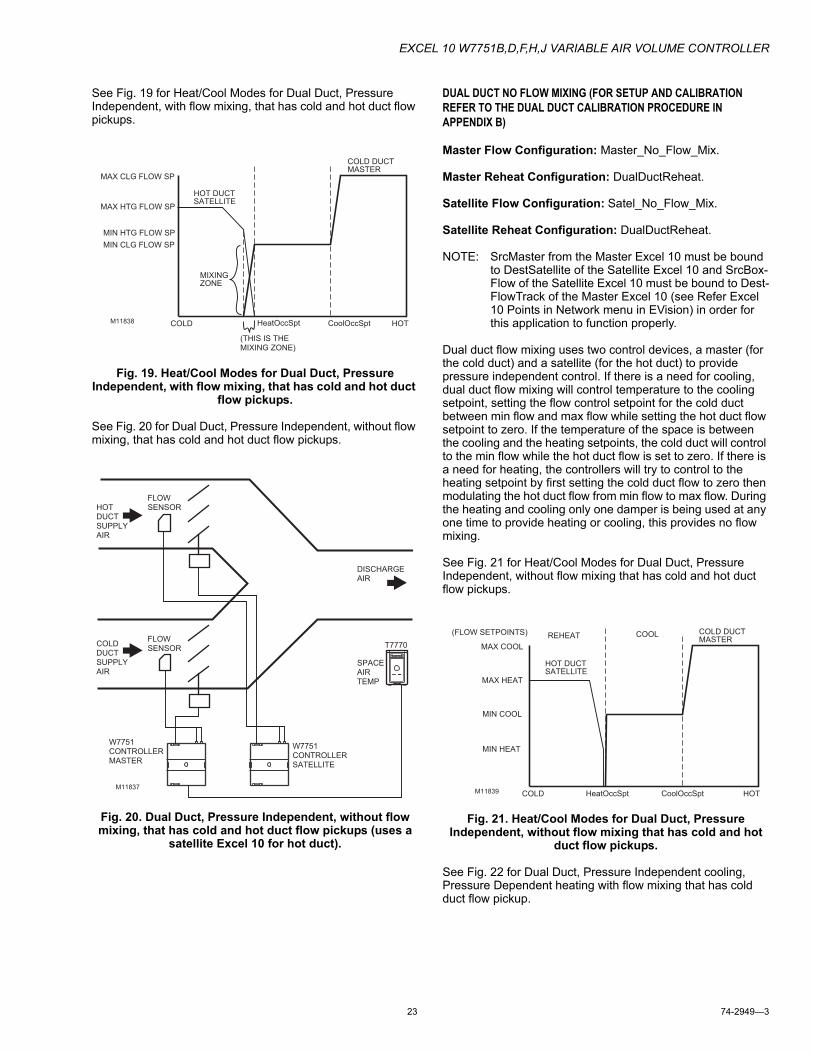
EXCEL 10 W7751B,D,F,H,J VARIABLE AIR VOLUME CONTROLLER
23 74-2949—3
See Fig. 19 for Heat/Cool Modes for Dual Duct, Pressure Independent, with flow mixing, that has cold and hot duct flow pickups.
Fig. 19. Heat/Cool Modes for Dual Duct, Pressure Independent, with flow mixing, that has cold and hot duct
flow pickups.
See Fig. 20 for Dual Duct, Pressure Independent, without flow mixing, that has cold and hot duct flow pickups.
Fig. 20. Dual Duct, Pressure Independent, without flow mixing, that has cold and hot duct flow pickups (uses a
satellite Excel 10 for hot duct).
DUAL DUCT NO FLOW MIXING (FOR SETUP AND CALIBRATION REFER TO THE DUAL DUCT CALIBRATION PROCEDURE IN APPENDIX B)
Master Flow Configuration: Master_No_Flow_Mix.
Master Reheat Configuration: DualDuctReheat.
Satellite Flow Configuration: Satel_No_Flow_Mix.
Satellite Reheat Configuration: DualDuctReheat.
NOTE: SrcMaster from the Master Excel 10 must be bound to DestSatellite of the Satellite Excel 10 and SrcBox-Flow of the Satellite Excel 10 must be bound to Dest-FlowTrack of the Master Excel 10 (see Refer Excel 10 Points in Network menu in EVision) in order for this application to function properly.
Dual duct flow mixing uses two control devices, a master (for the cold duct) and a satellite (for the hot duct) to provide pressure independent control. If there is a need for cooling, dual duct flow mixing will control temperature to the cooling setpoint, setting the flow control setpoint for the cold duct between min flow and max flow while setting the hot duct flow setpoint to zero. If the temperature of the space is between the cooling and the heating setpoints, the cold duct will control to the min flow while the hot duct flow is set to zero. If there is a need for heating, the controllers will try to control to the heating setpoint by first setting the cold duct flow to zero then modulating the hot duct flow from min flow to max flow. During the heating and cooling only one damper is being used at any one time to provide heating or cooling, this provides no flow mixing.
See Fig. 21 for Heat/Cool Modes for Dual Duct, Pressure Independent, without flow mixing that has cold and hot duct flow pickups.
Fig. 21. Heat/Cool Modes for Dual Duct, Pressure Independent, without flow mixing that has cold and hot
duct flow pickups.
See Fig. 22 for Dual Duct, Pressure Independent cooling, Pressure Dependent heating with flow mixing that has cold duct flow pickup.
M11838 COLD HOT
COLD DUCTMASTER
HOT DUCTSATELLITE
MAX CLG FLOW SP
MAX HTG FLOW SP
MIN HTG FLOW SP
MIN CLG FLOW SP
MIXINGZONE
HeatOccSpt CoolOccSpt
(THIS IS THEMIXING ZONE)
T7770
HOTDUCTSUPPLYAIR
COLDDUCTSUPPLYAIR
DISCHARGE AIR
FLOWSENSOR
FLOWSENSOR
W7751CONTROLLERMASTER
SPACEAIRTEMP
W7751CONTROLLERSATELLITE
M11837M11839 COLD HOT
COLD DUCTMASTER
HOT DUCTSATELLITE
MAX COOL
MAX HEAT
MIN HEAT
MIN COOL
REHEAT COOL
HeatOccSpt CoolOccSpt
(FLOW SETPOINTS)
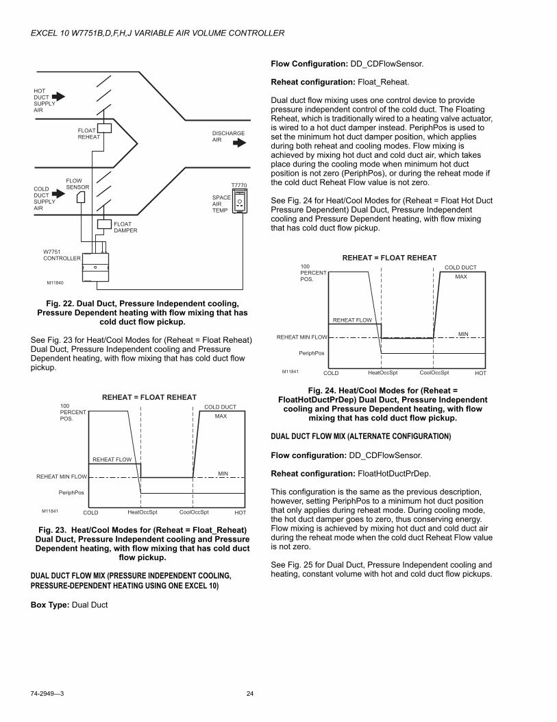
EXCEL 10 W7751B,D,F,H,J VARIABLE AIR VOLUME CONTROLLER
74-2949—3 24
Fig. 22. Dual Duct, Pressure Independent cooling, Pressure Dependent heating with flow mixing that has
cold duct flow pickup.
See Fig. 23 for Heat/Cool Modes for (Reheat = Float Reheat) Dual Duct, Pressure Independent cooling and Pressure Dependent heating, with flow mixing that has cold duct flow pickup.
Fig. 23. Heat/Cool Modes for (Reheat = Float_Reheat) Dual Duct, Pressure Independent cooling and Pressure Dependent heating, with flow mixing that has cold duct
flow pickup.
DUAL DUCT FLOW MIX (PRESSURE INDEPENDENT COOLING, PRESSURE-DEPENDENT HEATING USING ONE EXCEL 10)
Box Type: Dual Duct
Flow Configuration: DD_CDFlowSensor.
Reheat configuration: Float_Reheat.
Dual duct flow mixing uses one control device to provide pressure independent control of the cold duct. The Floating Reheat, which is traditionally wired to a heating valve actuator, is wired to a hot duct damper instead. PeriphPos is used to set the minimum hot duct damper position, which applies during both reheat and cooling modes. Flow mixing is achieved by mixing hot duct and cold duct air, which takes place during the cooling mode when minimum hot duct position is not zero (PeriphPos), or during the reheat mode if the cold duct Reheat Flow value is not zero.
See Fig. 24 for Heat/Cool Modes for (Reheat = Float Hot Duct Pressure Dependent) Dual Duct, Pressure Independent cooling and Pressure Dependent heating, with flow mixing that has cold duct flow pickup.
Fig. 24. Heat/Cool Modes for (Reheat = FloatHotDuctPrDep) Dual Duct, Pressure Independent
cooling and Pressure Dependent heating, with flow mixing that has cold duct flow pickup.
DUAL DUCT FLOW MIX (ALTERNATE CONFIGURATION)
Flow configuration: DD_CDFlowSensor.
Reheat configuration: FloatHotDuctPrDep.
This configuration is the same as the previous description, however, setting PeriphPos to a minimum hot duct position that only applies during reheat mode. During cooling mode, the hot duct damper goes to zero, thus conserving energy. Flow mixing is achieved by mixing hot duct and cold duct air during the reheat mode when the cold duct Reheat Flow value is not zero.
See Fig. 25 for Dual Duct, Pressure Independent cooling and heating, constant volume with hot and cold duct flow pickups.
T7770
HOTDUCTSUPPLYAIR
COLDDUCTSUPPLYAIR
DISCHARGE AIR
FLOWSENSOR
W7751CONTROLLER
SPACEAIRTEMP
M11840
FLOATREHEAT
FLOATDAMPER
M11841 COLD HOT
COLD DUCT
REHEAT FLOW
REHEAT MIN FLOW
MAX
MIN
REHEAT = FLOAT REHEAT100PERCENTPOS.
HeatOccSpt CoolOccSpt
PeriphPos
M11841 COLD HOT
COLD DUCT
REHEAT FLOW
REHEAT MIN FLOW
MAX
MIN
REHEAT = FLOAT REHEAT100PERCENTPOS.
HeatOccSpt CoolOccSpt
PeriphPos
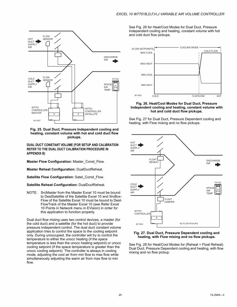
EXCEL 10 W7751B,D,F,H,J VARIABLE AIR VOLUME CONTROLLER
25 74-2949—3
Fig. 25. Dual Duct, Pressure Independent cooling and heating, constant volume with hot and cold duct flow
pickups.
DUAL DUCT CONSTANT VOLUME (FOR SETUP AND CALIBRATION REFER TO THE DUAL DUCT CALIBRATION PROCEDURE IN APPENDIX B)
Master Flow Configuration: Master_Const_Flow.
Master Reheat Configuration: DualDuctReheat.
Satellite Flow Configuration: Satel_Const_Flow.
Satellite Reheat Configuration: DualDuctReheat.
NOTE: SrcMaster from the Master Excel 10 must be bound to DestSatellite of the Satellite Excel 10 and SrcBox-Flow of the Satellite Excel 10 must be bound to Dest-FlowTrack of the Master Excel 10 (see Refer Excel 10 Points in Network menu in EVision) in order for this application to function properly.
Dual duct flow mixing uses two control devices, a master (for the cold duct) and a satellite (for the hot duct) to provide pressure independent control. The dual duct constant volume application tries to control the space to the cooling setpoint only. During unoccupied, the controller will try to control the temperature to either the unocc heating (if the space temperature is less than the unocc heating setpoint) or unocc cooling setpoint (if the space temperature is greater than the unocc cooling setpoint). The controller is always in cooling mode, adjusting the cool air from min flow to max flow while simultaneously adjusting the warm air from max flow to min flow.
See Fig. 26 for Heat/Cool Modes for Dual Duct, Pressure Independent cooling and heating, constant volume with hot and cold duct flow pickups.
Fig. 26. Heat/Cool Modes for Dual Duct, Pressure Independent cooling and heating, constant volume with
hot and cold duct flow pickups.
See Fig. 27 for Dual Duct, Pressure Dependent cooling and heating, with Flow mixing and no flow pickups.
Fig. 27. Dual Duct, Pressure Dependent cooling and heating, with Flow mixing and no flow pickups.
See Fig. 28 for Heat/Cool Modes for (Reheat = Float Reheat) Dual Duct, Pressure Dependent cooling and heating, with flow mixing and no flow pickup.
T7770
HOTDUCTSUPPLYAIR
COLDDUCTSUPPLYAIR
DISCHARGE AIR
FLOWSENSOR
FLOWSENSOR
W7751CONTROLLERMASTER
SPACEAIRTEMP
W7751CONTROLLERSATELLITE
M11837
M11843 COLD HOT
COLD FLOWMAX COOL
MAX HEAT
MIN HEAT
MIN COOL
CoolOccSpt
COOLING MODE(FLOW SETPOINTS)
T7770
HOTDUCTSUPPLYAIR
COLDDUCTSUPPLYAIR
DISCHARGE AIR
W7751CONTROLLER
SPACEAIRTEMP
M11844
FLOATREHEAT
FLOATDAMPER
NO FLOW PICKUPS
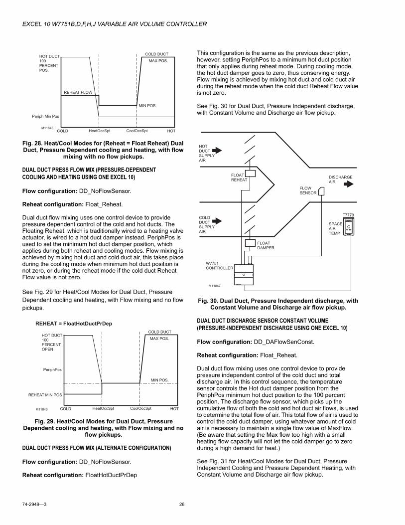
EXCEL 10 W7751B,D,F,H,J VARIABLE AIR VOLUME CONTROLLER
74-2949—3 26
Fig. 28. Heat/Cool Modes for (Reheat = Float Reheat) Dual Duct, Pressure Dependent cooling and heating, with flow
mixing with no flow pickups.
DUAL DUCT PRESS FLOW MIX (PRESSURE-DEPENDENT COOLING AND HEATING USING ONE EXCEL 10)
Flow configuration: DD_NoFlowSensor.
Reheat configuration: Float_Reheat.
Dual duct flow mixing uses one control device to provide pressure dependent control of the cold and hot ducts. The Floating Reheat, which is traditionally wired to a heating valve actuator, is wired to a hot duct damper instead. PeriphPos is used to set the minimum hot duct damper position, which applies during both reheat and cooling modes. Flow mixing is achieved by mixing hot duct and cold duct air, this takes place during the cooling mode when minimum hot duct position is not zero, or during the reheat mode if the cold duct Reheat Flow value is not zero.
See Fig. 29 for Heat/Cool Modes for Dual Duct, Pressure Dependent cooling and heating, with Flow mixing and no flow pickups.
Fig. 29. Heat/Cool Modes for Dual Duct, Pressure Dependent cooling and heating, with Flow mixing and no
flow pickups.
DUAL DUCT PRESS FLOW MIX (ALTERNATE CONFIGURATION)
Flow configuration: DD_NoFlowSensor.
Reheat configuration: FloatHotDuctPrDep
This configuration is the same as the previous description, however, setting PeriphPos to a minimum hot duct position that only applies during reheat mode. During cooling mode, the hot duct damper goes to zero, thus conserving energy. Flow mixing is achieved by mixing hot duct and cold duct air during the reheat mode when the cold duct Reheat Flow value is not zero.
See Fig. 30 for Dual Duct, Pressure Independent discharge, with Constant Volume and Discharge air flow pickup.
Fig. 30. Dual Duct, Pressure Independent discharge, with Constant Volume and Discharge air flow pickup.
DUAL DUCT DISCHARGE SENSOR CONSTANT VOLUME (PRESSURE-INDEPENDENT DISCHARGE USING ONE EXCEL 10)
Flow configuration: DD_DAFlowSenConst.
Reheat configuration: Float_Reheat.
Dual duct flow mixing uses one control device to provide pressure independent control of the cold duct and total discharge air. In this control sequence, the temperature sensor controls the Hot duct damper position from the PeriphPos minimum hot duct position to the 100 percent position. The discharge flow sensor, which picks up the cumulative flow of both the cold and hot duct air flows, is used to determine the total flow of air. This total flow of air is used to control the cold duct damper, using whatever amount of cold air is necessary to maintain a single flow value of MaxFlow. (Be aware that setting the Max flow too high with a small heating flow capacity will not let the cold damper go to zero during a high demand for heat.)
See Fig. 31 for Heat/Cool Modes for Dual Duct, Pressure Independent Cooling and Pressure Dependent Heating, with Constant Volume and Discharge air flow pickup.
M11845COLD HOT
COLD DUCT
REHEAT FLOW
MIN POS.
MAX POS.
HeatOccSpt CoolOccSpt
Periph Min Pos
HOT DUCT100PERCENTPOS.
M11846 COLD HOT
COLD DUCT
REHEAT MIN POS
MAX POS.
MIN POS.
REHEAT = FloatHotDuctPrDep
HOT DUCT100PERCENTOPEN
HeatOccSpt CoolOccSpt
PeriphPos
T7770
HOTDUCTSUPPLYAIR
COLDDUCTSUPPLYAIR
DISCHARGE AIR
FLOWSENSOR
W7751CONTROLLER
SPACEAIRTEMP
M11847
FLOATREHEAT
FLOATDAMPER
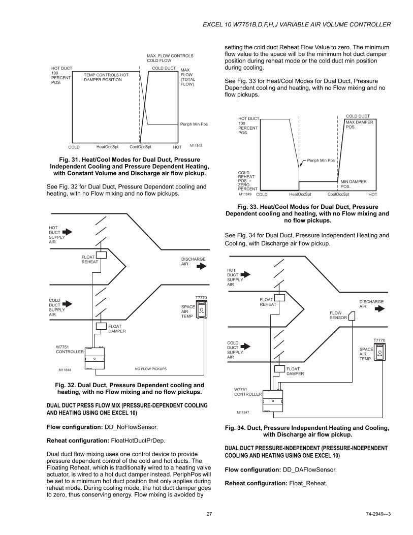
EXCEL 10 W7751B,D,F,H,J VARIABLE AIR VOLUME CONTROLLER
27 74-2949—3
Fig. 31. Heat/Cool Modes for Dual Duct, Pressure Independent Cooling and Pressure Dependent Heating, with Constant Volume and Discharge air flow pickup.
See Fig. 32 for Dual Duct, Pressure Dependent cooling and heating, with no Flow mixing and no flow pickups.
Fig. 32. Dual Duct, Pressure Dependent cooling and heating, with no Flow mixing and no flow pickups.
DUAL DUCT PRESS FLOW MIX (PRESSURE-DEPENDENT COOLING AND HEATING USING ONE EXCEL 10)
Flow configuration: DD_NoFlowSensor.
Reheat configuration: FloatHotDuctPrDep.
Dual duct flow mixing uses one control device to provide pressure dependent control of the cold and hot ducts. The Floating Reheat, which is traditionally wired to a heating valve actuator, is wired to a hot duct damper instead. PeriphPos will be set to a minimum hot duct position that only applies during reheat mode. During cooling mode, the hot duct damper goes to zero, thus conserving energy. Flow mixing is avoided by
setting the cold duct Reheat Flow Value to zero. The minimum flow value to the space will be the minimum hot duct damper position during reheat mode or the cold duct min position during cooling.
See Fig. 33 for Heat/Cool Modes for Dual Duct, Pressure Dependent cooling and heating, with no Flow mixing and no flow pickups.
Fig. 33. Heat/Cool Modes for Dual Duct, Pressure Dependent cooling and heating, with no Flow mixing and
no flow pickups.
See Fig. 34 for Dual Duct, Pressure Independent Heating and Cooling, with Discharge air flow pickup.
Fig. 34. Duct, Pressure Independent Heating and Cooling, with Discharge air flow pickup.
DUAL DUCT PRESSURE-INDEPENDENT (PRESSURE-INDEPENDENT COOLING AND HEATING USING ONE EXCEL 10)
Flow configuration: DD_DAFlowSensor.
Reheat configuration: Float_Reheat.
M11848COLD HOT
COLD DUCT
TEMP CONTROLS HOTDAMPER POSITION
MAX FLOW(TOTAL FLOW)
MAX. FLOW CONTROLSCOLD FLOW
HOT DUCT100PERCENTPOS.
HeatOccSpt CoolOccSpt
Periph Min Pos
T7770
HOTDUCTSUPPLYAIR
COLDDUCTSUPPLYAIR
DISCHARGE AIR
W7751CONTROLLER
SPACEAIRTEMP
M11844
FLOATREHEAT
FLOATDAMPER
NO FLOW PICKUPS
M11849 COLD HOT
COLD DUCT
MAX DAMPERPOS.
MIN DAMPERPOS.
COLD REHEATPOS. = ZEROPERCENT
HOT DUCT100PERCENTPOS.
HeatOccSpt CoolOccSpt
Periph Min Pos
T7770
HOTDUCTSUPPLYAIR
COLDDUCTSUPPLYAIR
DISCHARGE AIR
FLOWSENSOR
W7751CONTROLLER
SPACEAIRTEMP
M11847
FLOATREHEAT
FLOATDAMPER
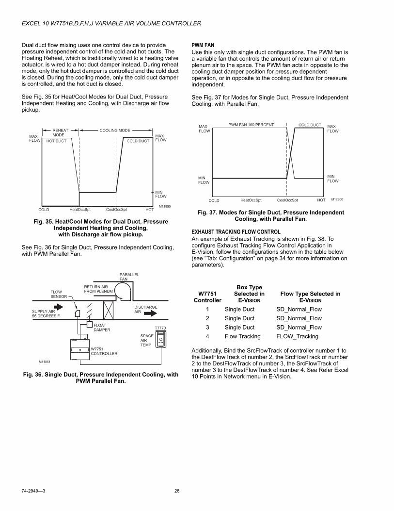
EXCEL 10 W7751B,D,F,H,J VARIABLE AIR VOLUME CONTROLLER
74-2949—3 28
Dual duct flow mixing uses one control device to provide pressure independent control of the cold and hot ducts. The Floating Reheat, which is traditionally wired to a heating valve actuator, is wired to a hot duct damper instead. During reheat mode, only the hot duct damper is controlled and the cold duct is closed. During the cooling mode, only the cold duct damper is controlled, and the hot duct is closed.
See Fig. 35 for Heat/Cool Modes for Dual Duct, Pressure Independent Heating and Cooling, with Discharge air flow pickup.
Fig. 35. Heat/Cool Modes for Dual Duct, Pressure Independent Heating and Cooling,
with Discharge air flow pickup.
See Fig. 36 for Single Duct, Pressure Independent Cooling, with PWM Parallel Fan.
Fig. 36. Single Duct, Pressure Independent Cooling, with PWM Parallel Fan.
PWM FANUse this only with single duct configurations. The PWM fan is a variable fan that controls the amount of return air or return plenum air to the space. The PWM fan acts in opposite to the cooling duct damper position for pressure dependent operation, or in opposite to the cooling duct flow for pressure independent.
See Fig. 37 for Modes for Single Duct, Pressure Independent Cooling, with Parallel Fan.
Fig. 37. Modes for Single Duct, Pressure Independent Cooling, with Parallel Fan.
EXHAUST TRACKING FLOW CONTROLAn example of Exhaust Tracking is shown in Fig. 38. To configure Exhaust Tracking Flow Control Application in E-Vision, follow the configurations shown in the table below (see “Tab: Configuration” on page 34 for more information on parameters).
Additionally, Bind the SrcFlowTrack of controller number 1 to the DestFlowTrack of number 2, the SrcFlowTrack of number 2 to the DestFlowTrack of number 3, the SrcFlowTrack of number 3 to the DestFlowTrack of number 4. See Refer Excel 10 Points in Network menu in E-Vision.
M11850COLD HOT
COLD DUCTHOT DUCTMAX FLOW
MIN FLOW
MAX FLOW
HeatOccSpt CoolOccSpt
REHEAT MODE
COOLING MODE
M11851
FLOWSENSOR
SUPPLY AIR55 DEGREES F
FLOATDAMPER
PARALLELFAN
DISCHARGEAIR
W7751CONTROLLER
T7770
SPACEAIRTEMP
RETURN AIRFROM PLENUM W7751
Controller
Box Type Selected in
E-VISIONFlow Type Selected in
E-VISION
1 Single Duct SD_Normal_Flow2 Single Duct SD_Normal_Flow3 Single Duct SD_Normal_Flow4 Flow Tracking FLOW_Tracking
M12800COLD HOT
COLD DUCTPWM FAN 100 PERCENT
MIN FLOW
MAX FLOW
MIN FLOW
MAX FLOW
HeatOccSpt CoolOccSpt
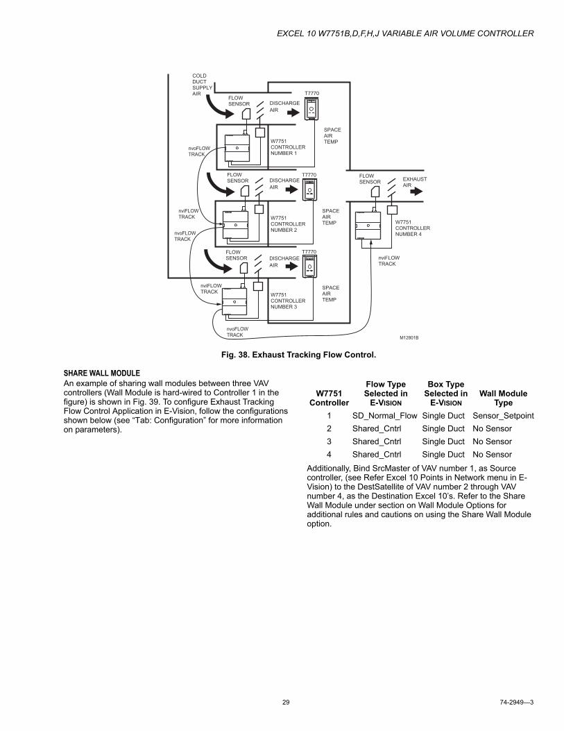
EXCEL 10 W7751B,D,F,H,J VARIABLE AIR VOLUME CONTROLLER
29 74-2949—3
Fig. 38. Exhaust Tracking Flow Control.
SHARE WALL MODULEAn example of sharing wall modules between three VAV controllers (Wall Module is hard-wired to Controller 1 in the figure) is shown in Fig. 39. To configure Exhaust Tracking Flow Control Application in E-Vision, follow the configurations shown below (see “Tab: Configuration” for more information on parameters).
Additionally, Bind SrcMaster of VAV number 1, as Source controller, (see Refer Excel 10 Points in Network menu in E-Vision) to the DestSatellite of VAV number 2 through VAV number 4, as the Destination Excel 10’s. Refer to the Share Wall Module under section on Wall Module Options for additional rules and cautions on using the Share Wall Module option.
COLD
DUCT
SUPPLY
AIR
EXHAUST
AIR
DISCHARGE
AIR
FLOW
SENSOR
T7770
SPACE
AIR
TEMPW7751
CONTROLLER
NUMBER 1
DISCHARGE
AIR
FLOW
SENSORT7770
SPACE
AIR
TEMPW7751
CONTROLLER
NUMBER 2
FLOW
SENSOR
W7751
CONTROLLER
NUMBER 4
DISCHARGE
AIR
FLOW
SENSOR
T7770
SPACE
AIR
TEMPW7751
CONTROLLER
NUMBER 3
nviFLOW
TRACK
nviFLOW
TRACK
nviFLOW
TRACK
nvoFLOW
TRACK
nvoFLOW
TRACK
nvoFLOW
TRACKM12801B
W7751 Controller
Flow Type Selected in
E-VISION
Box Type Selected in
E-VISIONWall Module
Type1 SD_Normal_Flow Single Duct Sensor_Setpoint2 Shared_Cntrl Single Duct No Sensor3 Shared_Cntrl Single Duct No Sensor4 Shared_Cntrl Single Duct No Sensor
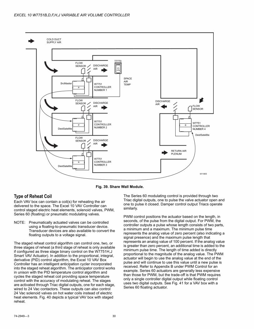
EXCEL 10 W7751B,D,F,H,J VARIABLE AIR VOLUME CONTROLLER
74-2949—3 30
Fig. 39. Share Wall Module.
Type of Reheat CoilEach VAV box can contain a coil(s) for reheating the air delivered to the space. The Excel 10 VAV Controller can control staged electric heat elements, solenoid valves, PWM, Series 60 (floating) or pneumatic modulating valves.
NOTE: Pneumatically actuated valves can be controlled using a floating-to-pneumatic transducer device. Transducer devices are also available to convert the floating outputs to a voltage signal.
The staged reheat control algorithm can control one, two, or three stages of reheat (a third stage of reheat is only available if configured as three stage binary control on the W7751H,J Smart VAV Actuator). In addition to the proportional, integral, derivative (PID) control algorithm, the Excel 10 VAV Box Controller has an intelligent anticipation cycler incorporated into the staged reheat algorithm. The anticipator control works in unison with the PID temperature control algorithm and cycles the staged reheat coil providing space temperature control with the accuracy of modulating reheat. The stages are activated through Triac digital outputs, one for each stage, wired to 24 Vac contactors. These outputs can also control 24 Vac solenoid valves on hot water coils instead of electric heat elements. Fig. 40 depicts a typical VAV box with staged reheat.
The Series 60 modulating control is provided through two Triac digital outputs, one to pulse the valve actuator open and one to pulse it closed. Damper control output Triacs operate similarly.
PWM control positions the actuator based on the length, in seconds, of the pulse from the digital output. For PWM, the controller outputs a pulse whose length consists of two parts, a minimum and a maximum. The minimum pulse time represents the analog value of zero percent (also indicating a signal presence) and the maximum pulse length that represents an analog value of 100 percent. If the analog value is greater than zero percent, an additional time is added to the minimum pulse time. The length of time added is directly proportional to the magnitude of the analog value. The PWM actuator will begin to use the analog value at the end of the pulse and will continue to use this value until a new pulse is received. Refer to Appendix B under PWM Control for an example. Series 60 actuators are generally less expensive than those for PWM, but the trade-off is that PWM requires only a single controller digital output while floating control uses two digital outputs. See Fig. 41 for a VAV box with a Series 60 floating actuator.
COLD DUCT
SUPPLY AIR
DISCHARGE
AIR
DISCHARGE
AIR
FLOW
SENSOR
T7770
SPACE
AIR
TEMPW7751
CONTROLLER
NUMBER 1
DISCHARGE
AIR
FLOW
SENSOR
W7751
CONTROLLER
NUMBER 2
FLOW
SENSOR
W7751
CONTROLLER
NUMBER 4
DISCHARGE
AIR
FLOW
SENSOR
W7751
CONTROLLER
NUMBER 3
M11865
RETURN AIR
PLENUM
SrcMaster
DestSatellite
DestSatellite
DestSatellite
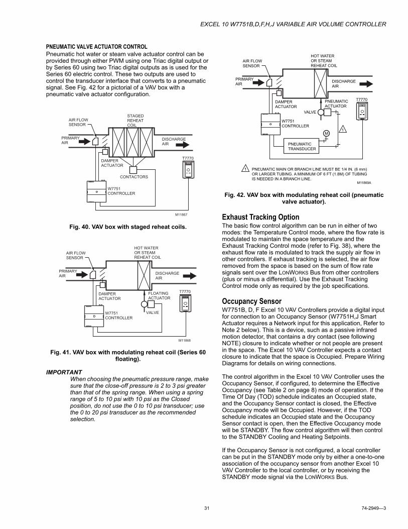
EXCEL 10 W7751B,D,F,H,J VARIABLE AIR VOLUME CONTROLLER
31 74-2949—3
PNEUMATIC VALVE ACTUATOR CONTROLPneumatic hot water or steam valve actuator control can be provided through either PWM using one Triac digital output or by Series 60 using two Triac digital outputs as is used for the Series 60 electric control. These two outputs are used to control the transducer interface that converts to a pneumatic signal. See Fig. 42 for a pictorial of a VAV box with a pneumatic valve actuator configuration.
Fig. 40. VAV box with staged reheat coils.
Fig. 41. VAV box with modulating reheat coil (Series 60 floating).
IMPORTANTWhen choosing the pneumatic pressure range, make sure that the close-off pressure is 2 to 3 psi greater than that of the spring range. When using a spring range of 5 to 10 psi with 10 psi as the Closed position, do not use the 0 to 10 psi transducer; use the 0 to 20 psi transducer as the recommended selection.
Fig. 42. VAV box with modulating reheat coil (pneumatic valve actuator).
Exhaust Tracking OptionThe basic flow control algorithm can be run in either of two modes: the Temperature Control mode, where the flow rate is modulated to maintain the space temperature and the Exhaust Tracking Control mode (refer to Fig. 38), where the exhaust flow rate is modulated to track the supply air flow in other controllers. If exhaust tracking is selected, the air flow removed from the space is based on the sum of flow rate signals sent over the LONWORKS Bus from other controllers (plus or minus a differential). Use the Exhaust Tracking Control mode only as required by the job specifications.
Occupancy SensorW7751B, D, F Excel 10 VAV Controllers provide a digital input for connection to an Occupancy Sensor (W7751H,J Smart Actuator requires a Network input for this application, Refer to Note 2 below). This is a device, such as a passive infrared motion detector, that contains a dry contact (see following NOTE) closure to indicate whether or not people are present in the space. The Excel 10 VAV Controller expects a contact closure to indicate that the space is Occupied. Prepare Wiring Diagrams for details on wiring connections.
The control algorithm in the Excel 10 VAV Controller uses the Occupancy Sensor, if configured, to determine the Effective Occupancy (see Table 2 on page 8) mode of operation. If the Time Of Day (TOD) schedule indicates an Occupied state, and the Occupancy Sensor contact is closed, the Effective Occupancy mode will be Occupied. However, if the TOD schedule indicates an Occupied state and the Occupancy Sensor contact is open, then the Effective Occupancy mode will be STANDBY. The flow control algorithm will then control to the STANDBY Cooling and Heating Setpoints.
If the Occupancy Sensor is not configured, a local controller can be put in the STANDBY mode only by either a one-to-one association of the occupancy sensor from another Excel 10 VAV Controller to the local controller, or by receiving the STANDBY mode signal via the LONWORKS Bus.
M11867
AIR FLOWSENSOR
PRIMARYAIR
DAMPER ACTUATOR
STAGEDREHEATCOIL
DISCHARGEAIR
CONTACTORS
W7751CONTROLLER
T7770
M11868
AIR FLOWSENSOR
PRIMARYAIR
DAMPER ACTUATOR
HOT WATEROR STEAMREHEAT COIL
DISCHARGEAIR
VALVEW7751CONTROLLER
FLOATINGACTUATOR
T7770
M11869A
AIR FLOW
SENSOR
PRIMARY
AIR
DAMPER
ACTUATOR
HOT WATER
OR STEAM
REHEAT COIL
DISCHARGE
AIR
VALVE
W7751
CONTROLLER
PNEUMATIC
ACTUATOR
PNEUMATIC
TRANSDUCER
M
1
1
PNEUMATIC MAIN OR BRANCH LINE MUST BE 1/4 IN. (6 mm)
OR LARGER TUBING. A MINIMUM OF 6 FT (1.8M) OF TUBING
IS NEEDED IN A BRANCH LINE.
T7770
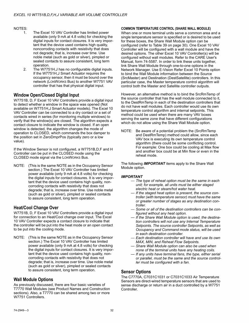
EXCEL 10 W7751B,D,F,H,J VARIABLE AIR VOLUME CONTROLLER
74-2949—3 32
NOTES:1. The Excel 10 VAV Controller has limited power
available (only 9 mA at 4.8 volts) for checking the digital inputs for contact closures. It is very impor-tant that the device used contains high quality, noncorroding contacts with resistivity that does not degrade; that is, increase over time. Use noble metal (such as gold or silver), pimpled or sealed contacts to assure consistent, long term operation.
2. The W7751H,J has no configurable digital inputs. If the W7751H,J Smart Actuator requires the occupancy sensor, then it must be bound over the network (LONWORKS Bus) to another W7751 VAV controller that has that physical digital input.
Window Open/Closed Digital InputW7751B, D, F Excel 10 VAV Controllers provide a digital input to detect whether a window in the space was opened (Not available on W7751H,J Smart Actuator models). The Excel 10 VAV Controller can be connected to a dry contact or a set of contacts wired in series (for monitoring multiple windows) to verify that the window(s) are closed. The algorithm expects a contact closure to indicate the window is closed. If an open window is detected, the algorithm changes the mode of operation to CLOSED, which commands the box damper to the position set in ZeroDmprPos (typically zero or a low value).
If the Window Sensor is not configured, a W7751B,D,F and H Controller can be put in the CLOSED mode using the CLOSED mode signal via the LONWORKS Bus.
NOTE: (This is the same NOTE as in the Occupancy Sensor section.) The Excel 10 VAV Controller has limited power available (only 9 mA at 4.8 volts) for checking the digital inputs for contact closures. It is very impor-tant that the device used contains high quality, non-corroding contacts with resistivity that does not degrade; that is, increase over time. Use noble metal (such as gold or silver), pimpled or sealed contacts to assure consistent, long term operation.
Heat/Cool Change OverW7751B, D, F Excel 10 VAV Controllers provide a digital input for connection to an Heat/Cool change over input. The Excel 10 VAV Controller expects a contact closure to indicate that the controller will be put into the heat mode or an open contact to be put into the cooling mode.
NOTE: (This is the same NOTE as in the Occupancy Sensor section.) The Excel 10 VAV Controller has limited power available (only 9 mA at 4.8 volts) for checking the digital inputs for contact closures. It is very impor-tant that the device used contains high quality, non-corroding contacts with resistivity that does not degrade; that is, increase over time. Use noble metal (such as gold or silver), pimpled or sealed contacts to assure consistent, long term operation.
Wall Module OptionsAs previously discussed, there are four basic varieties of T7770 Wall Modules (see Product Names and Construction sections). Also, a T7770 can be shared among two or more W7751 Controllers.
COMMON TEMPERATURE CONTROL (SHARE WALL MODULE)When one or more terminal units serve a common area and a single temperature sensor is specified or is desired to be used for these boxes, the Share Wall Module option can be configured (refer to Table 39 on page 30). One Excel 10 VAV Controller will be configured with a wall module and have the desired options. The other Excel 10 VAV Controller(s) will be configured without wall modules. Refer to the CARE User's Manual, form 74-5587. In order to link these units together, link Share Wall Module through one-to-one options in the Network Manager. Use E-Vision Refer Excel 10 Points option to bind the Wall Module information between the Source (SrcMaster) and Destination (DestSatellite) controllers. In this particular case, the Master temperature control algorithm will control both the Master and Satellite controller outputs.
However, an alternative method is to bind the SrcRmTemp of the source controller that has the wall module connected to it, to the DestRmTemp in each of the destination controllers that do not have wall modules. Each controller would use its own temperature control algorithm and internal setpoints. This method could be used when there are many VAV boxes serving the same zone that have different configurations which do not allow using the Share Wall Module option.
NOTE: Be aware of a potential problem the (SrcRmTemp and DestRmTemp) method could allow, since each VAV box is executing its own temperature control algorithm (there could be some conflicting control. For example: One box could be cooling at Max flow and another box could be at Min flow or even in the reheat mode.
The following IMPORTANT items apply to the Share Wall Module option.
IMPORTANT— The type of reheat option must be the same in each
unit; for example, all units must be either staged electric heat or steam/hot water heat.
— If the staged heat option is present, the source con-troller (with temperature sensor) must have the same or greater number of stages as any destination con-troller.
— Some or all of the destination controllers can be con-figured without any heat option.
— If the Share Wall Module option is used, the destina-tion controllers will not use any Internal Temperature Setpoints. The source controller Setpoints, as well as Occupancy and Command mode status, will be used in each destination controller.
— Each destination controller will have and use its own MAX, MIN, and Reheat Flow Setpoints.
— Share Wall Module option can also be used when none of the terminal units have any heating coils.
— If any units have terminal fans, the type, either serial or parallel, must be the same and the source control-ler must be configured with a fan.
Sensor OptionsThe C7770A, C7031C1031 or C7031C1033 Air Temperature Sensors are direct-wired temperature sensors that are used to sense discharge or return air in a duct controlled by a W7751 Controller.
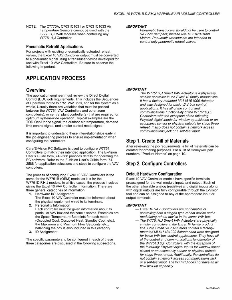
EXCEL 10 W7751B,D,F,H,J VARIABLE AIR VOLUME CONTROLLER
33 74-2949—3
NOTE: The C7770A, C7031C1031 or C7031C1033 Air Temperature Sensors cannot be used with the T7770B,C Wall Modules when controlling any W7751H,J Controller.
Pneumatic Retrofit ApplicationsFor projects with existing pneumatically-actuated reheat valves, the Excel 10 VAV Controller output must be converted to a pneumatic signal using a transducer device developed for use with Excel 10 VAV Controllers. Be sure to observe the following Important.
IMPORTANTPneumatic transducers should not be used to control VAV box dampers; Instead use ML6161B1000 Motors. Pneumatic transducers are intended to control only pneumatic reheat valves.
APPLICATION PROCESS
OverviewThe application engineer must review the Direct Digital Control (DDC) job requirements. This includes the Sequences of Operation for the W7751 VAV units, and for the system as a whole. Usually there are variables that must be passed between the W7751 VAV Controllers and other zone controller(s), or central plant controller(s) that are required for optimum system-wide operation. Typical examples are the TOD Occ/Unocc signal, the outdoor air temperature, demand limit control signal, and smoke control mode signal.
It is important to understand these interrelationships early in the job engineering process to ensure implementation when configuring the controllers.
Care/E-Vision PC Software is used to configure W7751 Controllers to match their intended application. The E-Vision User’s Guide form, 74-2588 provides details for operating the PC software. Refer to the E-Vision User’s Guide form, 74-2588 for application selections and steps to configure the VAV controllers.
The process of configuring Excel 10 VAV Controllers is the same for the W7751B (OEM) model as it is for the W7751D,F,H,J models. In all five cases, the process involves giving the Excel 10 VAV Controller information. There are three general categories of information:
1. Hardware I/O AssignmentThe Excel 10 VAV Controller must be informed about the physical equipment wired to its terminals.
2. Personality InformationEach controller must be given information about its particular VAV box and the zone it serves. Examples are the Space Temperature Setpoints for each mode (Occupied Cool, Occupied Heat, Standby Cool, etc.), the Maximum and Minimum Flow Setpoints, etc., balancing the box is also included in this category.
3. ID Assignment.
The specific parameters to be configured in each of these three categories are discussed in the following subsections.
IMPORTANTThe W7751H,J Smart VAV Actuator is a physically smaller controller in the Excel 10 family product line. It has a factory-mounted ML6161B1000 Actuator and was designed for basic VAV box control applications. It has all of the control and communications functionality of the W7751B,D,F Controllers with the exception of the following. Physical digital inputs for window open/closed or an occupancy sensor or physical outputs for stage three reheat. It also does not contain a network access communications jack or a self-test input.
Step 1. Create Bill of MaterialsAfter reviewing the job requirements, a bill of materials can be created for ordering purposes. For a list of Honeywell part numbers, “Product Names” on page 10.
Step 2. Configure Controllers
Default Hardware ConfigurationExcel 10 VAV Controller models have specific terminals preassigned for the wall module inputs and output. Each of the other allowable analog (resistive) and digital inputs along with digital outputs are fully configurable through the E-Vision tool and can be assigned to any of the appropriate input or output terminals.
IMPORTANT— Excel 10 VAV Controllers are not capable of
controlling both a staged type reheat device and a modulating reheat device in the same VAV box.
— The W7751H,J Smart VAV Actuators are physically smaller controllers in the Excel 10 family product line. Both Smart VAV Actuators contain a factory-mounted ML6161B1000 Actuator and were designed for basic VAV box control applications. They have all of the control and communications functionality of the W7751B,D,F Controllers with the exception of the following: Physical digital inputs for window open/closed or an occupancy sensor or physical outputs for stage three reheat. Additionally, the controllers do not contain a network access communications jack or a self-test input. The W7751J does not have an air flow pick-up capability.
EXCEL 10 W7751B,D,F,H,J VARIABLE AIR VOLUME CONTROLLER
74-2949—3 34
Configuration Screens for VAV ControllersThe configuration process is performed in a series of screens seen as file tabs under the menu option Controller> Application Selection in E-Vision. The following tables in this section list the options and variables found in each configuration screen. There are nine configuration screens (file tabs):
1. Configuration
2. Input
3. Output
4. Control Parameters
5. Misc Parameters
6. PID
7. Custom Output
8. Flow Pickup Table
9. Wiring
The specific parameters and equipment to be configured in each of these categories are tabulated in the following subsections.
NOTE: To set the following configuration parameters, use the E-Vision PC tool. These sections describe the various parameters and the allowable settings. For details on using E-Vision, refer to the E-Vision User Guide (form 74-2588).
TAB: CONFIGURATIONThe available options for the Configuration screen with the default values shown are listed in Table 5.
Table 5. VAV Controller Configuration Options.
Function Configuration options DefaultCross Reference
Heading(s)General Configuration
Controller Type Standard/OEMSmart Actuator
Standard_Controller “Description of Devices”
Pressure Type Pressure DependentPressure Independent
Pressure Independent “Pressure-Dependent/-Independent Control”
Box Type Single DuctDual DuctFlow Tracking
Single Duct “Single Duct Variable Air Volume (VAV) Systems”“Dual Duct Air Handling Systems”
Wall Module Type No SensorSensor OnlySensor OverrideSensor SetpointSensor_Spt_Ovrdride
Sensor_Spt_Ovrd “Wall Module Options”
Morning Warmup Type Fixed_Flow_SptMod_Flow_and_ReheatMod_Flow_No_Reheat
Fixed_Flow_Spt Morning Warmup
Flow Type Depends on Box Type and Pressure Type; see below for combinations allowed.
Flow Normal “Zone Control Definitions”
Reheat Type No ReheatOne Stage ReheatTwo Stage ReheatThree Stage ReheatThree Stage Bin ReheatOne Stage PeriphFloat ReheatFloat Periph ReheatFloat Reheat Then PeriphFloat Periph Then ReheatPWM ReheatPWM PeriphPWM Periph then ReheatPWM Reheat Then Periph
No Reheat “Type of Reheat Coil”
Also see Reheat Definitions below.
Fan Type No FanSerial FanParallel Temp ControlParallel Flow ControlParallel PWM Control
Serial Fan “Type of Box Fan”
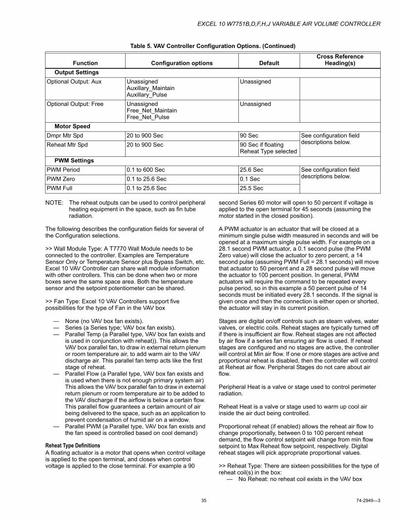
EXCEL 10 W7751B,D,F,H,J VARIABLE AIR VOLUME CONTROLLER
35 74-2949—3
NOTE: The reheat outputs can be used to control peripheral heating equipment in the space, such as fin tube radiation.
The following describes the configuration fields for several of the Configuration selections.
>> Wall Module Type: A T7770 Wall Module needs to be connected to the controller. Examples are Temperature Sensor Only or Temperature Sensor plus Bypass Switch, etc. Excel 10 VAV Controller can share wall module information with other controllers. This can be done when two or more boxes serve the same space area. Both the temperature sensor and the setpoint potentiometer can be shared.
>> Fan Type: Excel 10 VAV Controllers support five possibilities for the type of Fan in the VAV box
— None (no VAV box fan exists).— Series (a Series type; VAV box fan exists).— Parallel Temp (a Parallel type, VAV box fan exists and
is used in conjunction with reheat)). This allows the VAV box parallel fan, to draw in external return plenum or room temperature air, to add warm air to the VAV discharge air. This parallel fan temp acts like the first stage of reheat.
— Parallel Flow (a Parallel type, VAV box fan exists and is used when there is not enough primary system air) This allows the VAV box parallel fan to draw in external return plenum or room temperature air to be added to the VAV discharge if the airflow is below a certain flow. This parallel flow guarantees a certain amount of air being delivered to the space, such as an application to prevent condensation of humid air on a window.
— Parallel PWM (a Parallel type, VAV box fan exists and the fan speed is controlled based on cool demand)
Reheat Type DefinitionsA floating actuator is a motor that opens when control voltage is applied to the open terminal, and closes when control voltage is applied to the close terminal. For example a 90
second Series 60 motor will open to 50 percent if voltage is applied to the open terminal for 45 seconds (assuming the motor started in the closed position).
A PWM actuator is an actuator that will be closed at a minimum single pulse width measured in seconds and will be opened at a maximum single pulse width. For example on a 28.1 second PWM actuator, a 0.1 second pulse (the PWM Zero value) will close the actuator to zero percent, a 14 second pulse (assuming PWM Full = 28.1 seconds) will move that actuator to 50 percent and a 28 second pulse will move the actuator to 100 percent position. In general, PWM actuators will require the command to be repeated every pulse period, so in this example a 50 percent pulse of 14 seconds must be initiated every 28.1 seconds. If the signal is given once and then the connection is either open or shorted, the actuator will stay in its current position.
Stages are digital on/off controls such as steam valves, water valves, or electric coils. Reheat stages are typically turned off if there is insufficient air flow. Reheat stages are not affected by air flow if a series fan ensuring air flow is used. If reheat stages are configured and no stages are active, the controller will control at Min air flow. If one or more stages are active and proportional reheat is disabled, then the controller will control at Reheat air flow. Peripheral Stages do not care about air flow.
Peripheral Heat is a valve or stage used to control perimeter radiation.
Reheat Heat is a valve or stage used to warm up cool air inside the air duct being controlled.
Proportional reheat (if enabled) allows the reheat air flow to change proportionally, between 0 to 100 percent reheat demand, the flow control setpoint will change from min flow setpoint to Max Reheat flow setpoint, respectively. Digital reheat stages will pick appropriate proportional values.
>> Reheat Type: There are sixteen possibilities for the type of reheat coil(s) in the box:
— No Reheat: no reheat coil exists in the VAV box
Output SettingsOptional Output: Aux Unassigned
Auxillary_MaintainAuxillary_Pulse
Unassigned
Optional Output: Free UnassignedFree_Net_MaintainFree_Net_Pulse
Unassigned
Motor SpeedDmpr Mtr Spd 20 to 900 Sec 90 Sec See configuration field
descriptions below.Reheat Mtr Spd 20 to 900 Sec 90 Sec if floating Reheat Type selected
PWM SettingsPWM Period 0.1 to 600 Sec 25.6 Sec See configuration field
descriptions below.PWM Zero 0.1 to 25.6 Sec 0.1 SecPWM Full 0.1 to 25.6 Sec 25.5 Sec
Table 5. VAV Controller Configuration Options. (Continued)
Function Configuration options DefaultCross Reference
Heading(s)
EXCEL 10 W7751B,D,F,H,J VARIABLE AIR VOLUME CONTROLLER
74-2949—3 36
— One Stage Reheat: a staged On/Off control only, reheat coil exists in the box
— Two Stage Reheat: two stages of reheat exist in the VAV box
— Three Stage Reheat: three stages of reheat exist in the VAV box; not available for the W7751H,J.
— Three Stage Bin Reheat: using two physical stages of reheat controlled as three, for example: stage 1, stage 2, then stage 1 and 2 together. This type of reheat works similar to a 3-way light bulb: Off, low, medium and high using just two elements; available on the W7751H,J.
— One Stage Periph: a staged On/Off control only, baseboard radiation is an example of peripheral heating. This stage is not affected by air flow safeties.
— Float Reheat**: Modulating reheat valve (Series 60 floating control provided through two Digital Output points, one that pulses to open a steam or hot water valve and one that pulses to close the valve. Minimum position refers to the network variable nciAux1SetPt.ubPeriphMinPosS1.
— Float Periph Reheat* One modulating peripheral reheat stage. Stages is controlled via floating motor.
— Float Reheat Then Periph* One modulating reheat stage and one modulating peripheral reheat stage. Both stages are controlled via floating motors. Control turns on reheat valve first then peripheral valve.
— Float Periph Then Reheat* One modulating peripheral reheat stage and one modulating reheat stage. Both stages are controlled via floating motors. Control turns on peripheral reheat valve first then reheat valve.
— PWM ReHeat** One modulating reheat stage controlling via a pulse width modulation motor.
— PWM Periph* One modulating Peripheral reheat stage controlling via a pulse width modulation motor.
— PWM Periph then ReHeat* One modulating reheat stage and one modulating peripheral reheat stage. Both stages are controlled via a pulse width modula-tion motor. Control turns on peripheral valve first then reheat valve.
— PWM ReHeat then Periph* One modulating reheat stage and one modulating peripheral reheat stage. Both stages are controlled via a pulse width modulation motor. Control turns on reheat valve first then peripheral valve.
— Dual Duct Reheat: Reheating provided by second hot duct. A satellite controller can be used in conjunction with the master controller to control the hot duct.
— Float Hotduct Pressure Dependent*** Reheating using a hot duct damper controlled by the floating reheat outputs in the pressure dependent case only.
NOTES: Pneumatic hot water valves can be controlled with an MMC325 Pneumatic Transducer.* applies minimum position to the peripheral value
during all modes (Cooling, Reheat, Etc.).** applies minimum position to the reheat value
during all modes (Cooling, Reheat, Etc.).*** applies minimum position to the reheat value
during all modes except Cooling.
>> Flow Type: The flow type defines the control flow algorithm used by the controller. The selection available depends on the Pressure Type and the Box Type that are selected in the Configuration Screen.
— Flow Normal: The flow is controlled to satisfy the tem-perature control algorithm.
— Flow Tracking: The temperature control is turned off and the air flow setpoint equals the sum of SrcFlowTrack and Flow Offset (Control Parameters). Flow tracking can be used to pressurize or de-pressurize an area by having one or more VAV boxes deliver air to the space and one or more exhaust air from the space. By delivering or exhausting more air than is normally exhausted or delivered, the space can be pressurized or de- pressurized. Typically one or more boxes deliver air to the space and one box exhausts air from the space. Several nodes (controlling incoming air) can be bound in a daisy-chain to sum the total incoming flow. The last incoming air node is bound to the exhaust node. This setting is automatically selected if Pressure Type of Pressure Independent and Box Type of Flow Tracking are selected.
— Share Wall Module: The temperature control loop is turned off and the flow is controlled by the wall module at another node. In this case nvoShare is bound to nviShare of another node and the information received in nvoShare is used to control the air flow. The other node has the temperature sensor connected to it and controls the space temperature by its own damper and the other dampers of all nodes bound to it. This feature (Single Duct Box Type only), is used when only one temperature sensor is used in a large area to control several nodes.
— DD Master Constant Volume: The master node is connected to a cold air supply duct in a dual duct application and controls the air flow to the space. The satellite is connected to the hot duct. The master commands the satellite nodes damper via DestSatellite. The temperature control loop in the master is enabled and the temperature control loop in the satellite is disabled. Both the master and satellite have air flow sensors. The master controls the satellite so that the total air supplied is always a constant volume. When cooling is called, more Cool air is supplied to the space. When heating is called, more warm air is supplied to the space.
— DD Satel Constant Volume: Refer to the description above for DD Master Constant Volume.
— DD Master Flow Mix: The master node is connected to a cold air supply duct in a dual duct application and controls the air flow to the space. The satellite node is connected to the hot duct. The master node com-mands the satellite nodes damper via DestSatellite. Both the master and satellite have air flow sensors. The temperature control loop is enabled in the master and disabled in the satellite. Both warm air and cold air can be supplied to the space at the same time in the transition from heating to cooling or from cooling to heating - Flow mixing.
— DD Satel Flow Mix: Refer to the description for DD Master Flow Mix.
— DD Master No Flow Mix: Master node is connected to a cold air supply duct in a dual duct application and controls the air flow to the space. The satellite node is connected to the hot duct. Master node commands the satellite nodes damper via DestSatellite. Both the master and satellite have air flow sensors. The temperature control loop is enabled in the master and
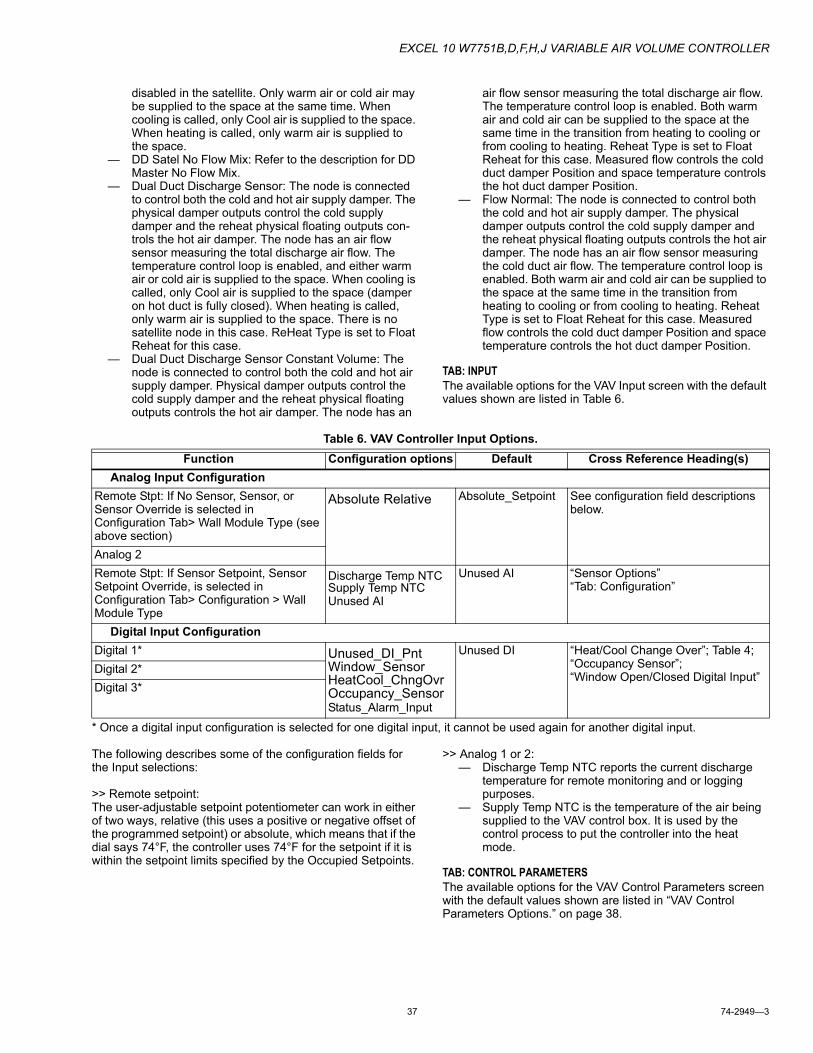
EXCEL 10 W7751B,D,F,H,J VARIABLE AIR VOLUME CONTROLLER
37 74-2949—3
disabled in the satellite. Only warm air or cold air may be supplied to the space at the same time. When cooling is called, only Cool air is supplied to the space. When heating is called, only warm air is supplied to the space.
— DD Satel No Flow Mix: Refer to the description for DD Master No Flow Mix.
— Dual Duct Discharge Sensor: The node is connected to control both the cold and hot air supply damper. The physical damper outputs control the cold supply damper and the reheat physical floating outputs con-trols the hot air damper. The node has an air flow sensor measuring the total discharge air flow. The temperature control loop is enabled, and either warm air or cold air is supplied to the space. When cooling is called, only Cool air is supplied to the space (damper on hot duct is fully closed). When heating is called, only warm air is supplied to the space. There is no satellite node in this case. ReHeat Type is set to Float Reheat for this case.
— Dual Duct Discharge Sensor Constant Volume: The node is connected to control both the cold and hot air supply damper. Physical damper outputs control the cold supply damper and the reheat physical floating outputs controls the hot air damper. The node has an
air flow sensor measuring the total discharge air flow. The temperature control loop is enabled. Both warm air and cold air can be supplied to the space at the same time in the transition from heating to cooling or from cooling to heating. Reheat Type is set to Float Reheat for this case. Measured flow controls the cold duct damper Position and space temperature controls the hot duct damper Position.
— Flow Normal: The node is connected to control both the cold and hot air supply damper. The physical damper outputs control the cold supply damper and the reheat physical floating outputs controls the hot air damper. The node has an air flow sensor measuring the cold duct air flow. The temperature control loop is enabled. Both warm air and cold air can be supplied to the space at the same time in the transition from heating to cooling or from cooling to heating. Reheat Type is set to Float Reheat for this case. Measured flow controls the cold duct damper Position and space temperature controls the hot duct damper Position.
TAB: INPUTThe available options for the VAV Input screen with the default values shown are listed in Table 6.
Table 6. VAV Controller Input Options.
* Once a digital input configuration is selected for one digital input, it cannot be used again for another digital input.
The following describes some of the configuration fields for the Input selections:
>> Remote setpoint:The user-adjustable setpoint potentiometer can work in either of two ways, relative (this uses a positive or negative offset of the programmed setpoint) or absolute, which means that if the dial says 74°F, the controller uses 74°F for the setpoint if it is within the setpoint limits specified by the Occupied Setpoints.
>> Analog 1 or 2: — Discharge Temp NTC reports the current discharge
temperature for remote monitoring and or logging purposes.
— Supply Temp NTC is the temperature of the air being supplied to the VAV control box. It is used by the control process to put the controller into the heat mode.
TAB: CONTROL PARAMETERSThe available options for the VAV Control Parameters screen with the default values shown are listed in “VAV Control Parameters Options.” on page 38.
Function Configuration options Default Cross Reference Heading(s)Analog Input Configuration
Remote Stpt: If No Sensor, Sensor, or Sensor Override is selected in Configuration Tab> Wall Module Type (see above section)
Absolute Relative Absolute_Setpoint See configuration field descriptions below.
Analog 2Remote Stpt: If Sensor Setpoint, Sensor Setpoint Override, is selected in Configuration Tab> Configuration > Wall Module Type
Discharge Temp NTCSupply Temp NTCUnused AI
Unused AI “Sensor Options”“Tab: Configuration”
Digital Input ConfigurationDigital 1* Unused_DI_Pnt
Window_SensorHeatCool_ChngOvrOccupancy_SensorStatus_Alarm_Input
Unused DI “Heat/Cool Change Over”; Table 4; “Occupancy Sensor”; “Window Open/Closed Digital Input”
Digital 2*Digital 3*
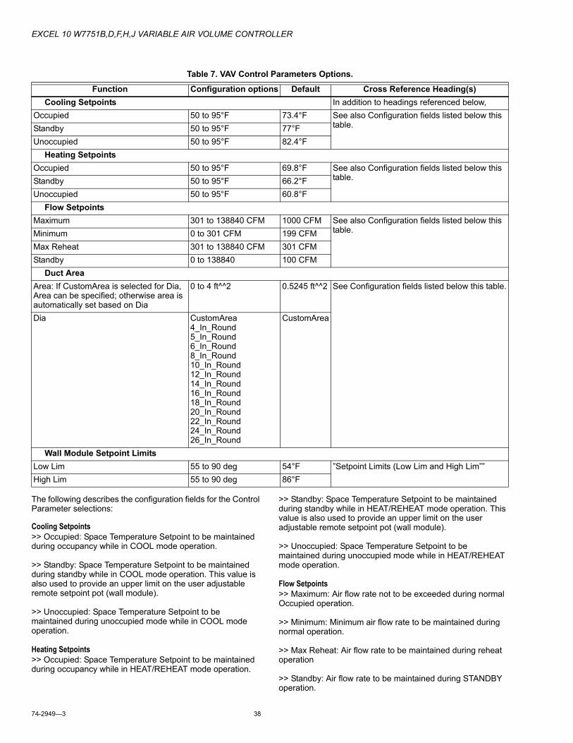
EXCEL 10 W7751B,D,F,H,J VARIABLE AIR VOLUME CONTROLLER
74-2949—3 38
The following describes the configuration fields for the Control Parameter selections:
Cooling Setpoints>> Occupied: Space Temperature Setpoint to be maintained during occupancy while in COOL mode operation.
>> Standby: Space Temperature Setpoint to be maintained during standby while in COOL mode operation. This value is also used to provide an upper limit on the user adjustable remote setpoint pot (wall module).
>> Unoccupied: Space Temperature Setpoint to be maintained during unoccupied mode while in COOL mode operation.
Heating Setpoints>> Occupied: Space Temperature Setpoint to be maintained during occupancy while in HEAT/REHEAT mode operation.
>> Standby: Space Temperature Setpoint to be maintained during standby while in HEAT/REHEAT mode operation. This value is also used to provide an upper limit on the user adjustable remote setpoint pot (wall module).
>> Unoccupied: Space Temperature Setpoint to be maintained during unoccupied mode while in HEAT/REHEAT mode operation.
Flow Setpoints>> Maximum: Air flow rate not to be exceeded during normal Occupied operation.
>> Minimum: Minimum air flow rate to be maintained during normal operation.
>> Max Reheat: Air flow rate to be maintained during reheat operation
>> Standby: Air flow rate to be maintained during STANDBY operation.
Table 7. VAV Control Parameters Options.
Function Configuration options Default Cross Reference Heading(s)Cooling Setpoints In addition to headings referenced below,
Occupied 50 to 95°F 73.4°F See also Configuration fields listed below this table.Standby 50 to 95°F 77°F
Unoccupied 50 to 95°F 82.4°FHeating Setpoints
Occupied 50 to 95°F 69.8°F See also Configuration fields listed below this table.Standby 50 to 95°F 66.2°F
Unoccupied 50 to 95°F 60.8°FFlow Setpoints
Maximum 301 to 138840 CFM 1000 CFM See also Configuration fields listed below this table.Minimum 0 to 301 CFM 199 CFM
Max Reheat 301 to 138840 CFM 301 CFMStandby 0 to 138840 100 CFM
Duct AreaArea: If CustomArea is selected for Dia, Area can be specified; otherwise area is automatically set based on Dia
0 to 4 ft^^2 0.5245 ft^^2 See Configuration fields listed below this table.
Dia CustomArea4_In_Round5_In_Round6_In_Round8_In_Round10_In_Round12_In_Round14_In_Round16_In_Round18_In_Round20_In_Round22_In_Round24_In_Round26_In_Round
CustomArea
Wall Module Setpoint LimitsLow Lim 55 to 90 deg 54°F ”Setpoint Limits (Low Lim and High Lim””High Lim 55 to 90 deg 86°F
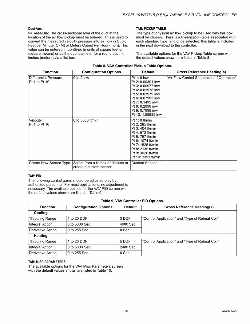
EXCEL 10 W7751B,D,F,H,J VARIABLE AIR VOLUME CONTROLLER
39 74-2949—3
Duct Area>> Area/Dia: The cross-sectional area of the duct at the location of the air flow pickup must be entered. This is used to convert the measured velocity pressure into air flow in Cubic Feet per Minute (CFM) or Meters Cubed Per Hour (m3h). This value can be entered in LONSPEC in units of square feet or (square meters) or as the duct diameter for a round duct, in inches (meters) via a list box.
TAB: PICKUP TABLEThe type of physical air flow pickup to be used with this box must be chosen. There is a linearization table associated with each standard type, and once selected, this table is included in the next download to the controller.
The available options for the VAV Pickup Table screen with the default values shown are listed in Table 8.
Table 8. VAV Controller Pickup Table Options.
TAB: PIDThe following control gains should be adjusted only by authorized personnel. For most applications, no adjustment is necessary. The available options for the VAV PID screen with the default values shown are listed in Table 9.
Table 9. VAV Controller PID Options.
TAB: MISC PARAMETERSThe available options for the VAV Misc Parameters screen with the default values shown are listed in Table 10.
Function Configuration Options Default Cross Reference Heading(s)Differential Pressure, Pt 1 to Pt 10
0 to 2 inw Pt 1: 0 inwPt 2: 0.00391 inwPt 3: 0.00977 inwPt 4: 0.01978 inwPt 5: 0.03979 inwPt 6: 0.07983 inwPt 7: 0.1499 inwPt 8: 0.2998 inwPt 9: 0.7998 inwPt 10: 1.59985 inw
“Air Flow Control Sequences of Operation”
Velocity, Pt 1 to Pt 10
0 to 3500 ft/min Pt 1: 0 ft/minPt 2: 285 ft/minPt 3: 404 ft/minPt 4: 572 ft/minPt 5: 757 ft/minPt 6: 1074 ft/minPt 7: 1526 ft/minPt 8: 2139 ft/minPt 9: 3026 ft/minPt 10: 3391 ft/min
Create New Sensor Type Select from a listbox of choices or create a custom sensor
Custom Sensor
Function Configuration Options Default Cross Reference Heading(s)Cooling
Throttling Range 1 to 20 DDF 3 DDF “Control Application” and “Type of Reheat Coil”Integral Action 0 to 5000 Sec 4000 SecDerivative Action 0 to 255 Sec 0 Sec
HeatingThrottling Range 1 to 20 DDF 5 DDF “Control Application” and “Type of Reheat Coil”Integral Action 0 to 5000 Sec 2400 SecDerivative Action 0 to 255 Sec 0 Sec
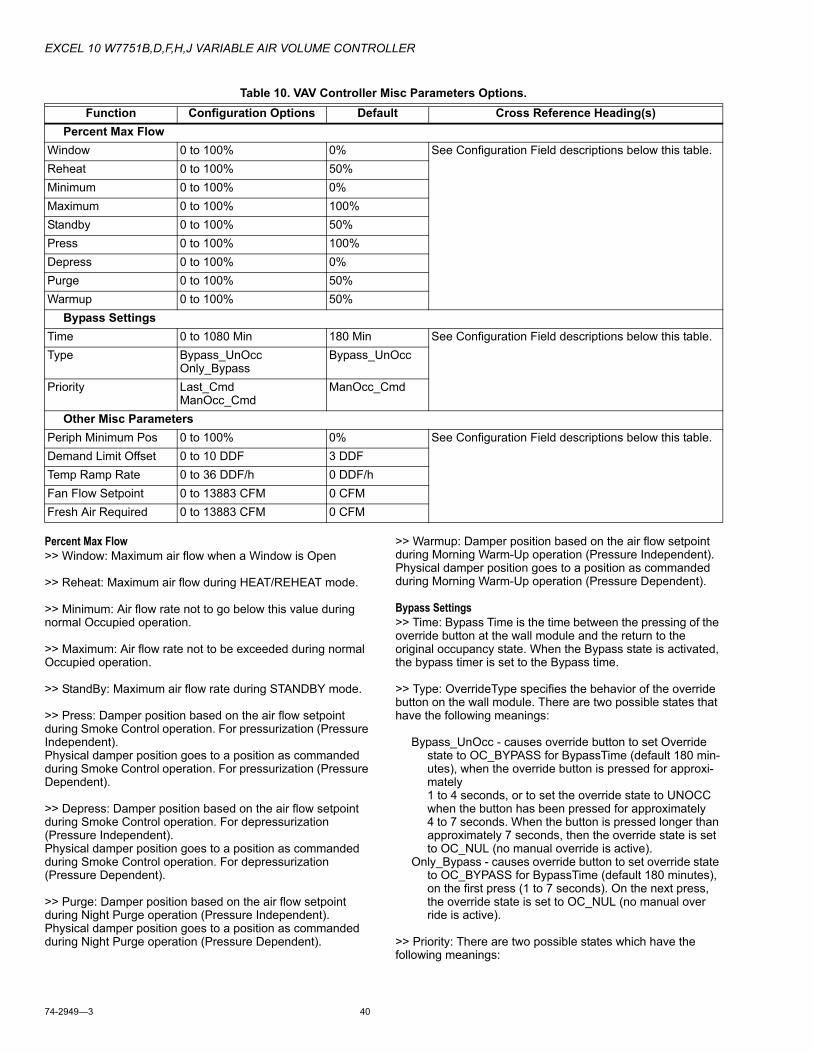
EXCEL 10 W7751B,D,F,H,J VARIABLE AIR VOLUME CONTROLLER
74-2949—3 40
Table 10. VAV Controller Misc Parameters Options.
Percent Max Flow>> Window: Maximum air flow when a Window is Open
>> Reheat: Maximum air flow during HEAT/REHEAT mode.
>> Minimum: Air flow rate not to go below this value during normal Occupied operation.
>> Maximum: Air flow rate not to be exceeded during normal Occupied operation.
>> StandBy: Maximum air flow rate during STANDBY mode.
>> Press: Damper position based on the air flow setpoint during Smoke Control operation. For pressurization (Pressure Independent).Physical damper position goes to a position as commanded during Smoke Control operation. For pressurization (Pressure Dependent).
>> Depress: Damper position based on the air flow setpoint during Smoke Control operation. For depressurization (Pressure Independent).Physical damper position goes to a position as commanded during Smoke Control operation. For depressurization (Pressure Dependent).
>> Purge: Damper position based on the air flow setpoint during Night Purge operation (Pressure Independent).Physical damper position goes to a position as commanded during Night Purge operation (Pressure Dependent).
>> Warmup: Damper position based on the air flow setpoint during Morning Warm-Up operation (Pressure Independent).Physical damper position goes to a position as commanded during Morning Warm-Up operation (Pressure Dependent).
Bypass Settings>> Time: Bypass Time is the time between the pressing of the override button at the wall module and the return to the original occupancy state. When the Bypass state is activated, the bypass timer is set to the Bypass time.
>> Type: OverrideType specifies the behavior of the override button on the wall module. There are two possible states that have the following meanings:
Bypass_UnOcc - causes override button to set Override state to OC_BYPASS for BypassTime (default 180 min-utes), when the override button is pressed for approxi-mately 1 to 4 seconds, or to set the override state to UNOCC when the button has been pressed for approximately 4 to 7 seconds. When the button is pressed longer than approximately 7 seconds, then the override state is set to OC_NUL (no manual override is active).
Only_Bypass - causes override button to set override state to OC_BYPASS for BypassTime (default 180 minutes), on the first press (1 to 7 seconds). On the next press, the override state is set to OC_NUL (no manual over ride is active).
>> Priority: There are two possible states which have the following meanings:
Function Configuration Options Default Cross Reference Heading(s)Percent Max Flow
Window 0 to 100% 0% See Configuration Field descriptions below this table.Reheat 0 to 100% 50%Minimum 0 to 100% 0%Maximum 0 to 100% 100%Standby 0 to 100% 50%Press 0 to 100% 100%Depress 0 to 100% 0%Purge 0 to 100% 50%Warmup 0 to 100% 50%
Bypass SettingsTime 0 to 1080 Min 180 Min See Configuration Field descriptions below this table.Type Bypass_UnOcc
Only_BypassBypass_UnOcc
Priority Last_CmdManOcc_Cmd
ManOcc_Cmd
Other Misc ParametersPeriph Minimum Pos 0 to 100% 0% See Configuration Field descriptions below this table.Demand Limit Offset 0 to 10 DDF 3 DDFTemp Ramp Rate 0 to 36 DDF/h 0 DDF/hFan Flow Setpoint 0 to 13883 CFM 0 CFMFresh Air Required 0 to 13883 CFM 0 CFM
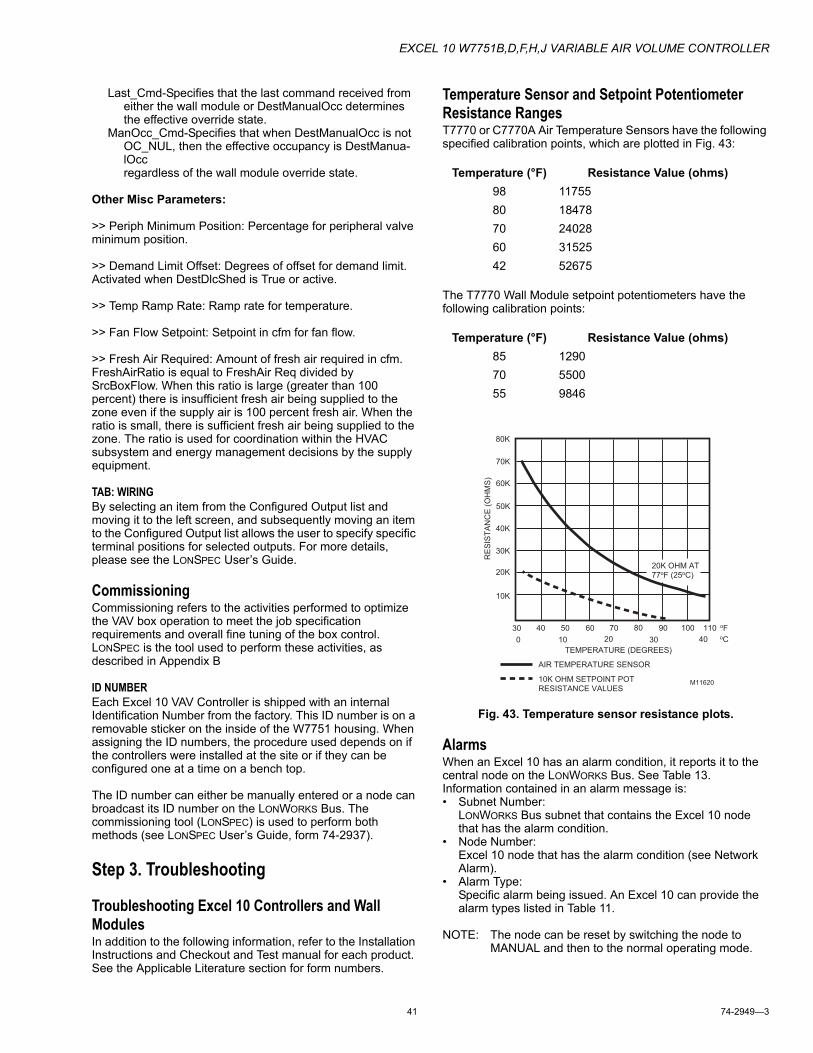
EXCEL 10 W7751B,D,F,H,J VARIABLE AIR VOLUME CONTROLLER
41 74-2949—3
Last_Cmd-Specifies that the last command received from either the wall module or DestManualOcc determines the effective override state.
ManOcc_Cmd-Specifies that when DestManualOcc is not OC_NUL, then the effective occupancy is DestManua-lOcc regardless of the wall module override state.
Other Misc Parameters:
>> Periph Minimum Position: Percentage for peripheral valve minimum position.
>> Demand Limit Offset: Degrees of offset for demand limit. Activated when DestDlcShed is True or active.
>> Temp Ramp Rate: Ramp rate for temperature.
>> Fan Flow Setpoint: Setpoint in cfm for fan flow.
>> Fresh Air Required: Amount of fresh air required in cfm. FreshAirRatio is equal to FreshAir Req divided by SrcBoxFlow. When this ratio is large (greater than 100 percent) there is insufficient fresh air being supplied to the zone even if the supply air is 100 percent fresh air. When the ratio is small, there is sufficient fresh air being supplied to the zone. The ratio is used for coordination within the HVAC subsystem and energy management decisions by the supply equipment.
TAB: WIRINGBy selecting an item from the Configured Output list and moving it to the left screen, and subsequently moving an item to the Configured Output list allows the user to specify specific terminal positions for selected outputs. For more details, please see the LONSPEC User’s Guide.
CommissioningCommissioning refers to the activities performed to optimize the VAV box operation to meet the job specification requirements and overall fine tuning of the box control. LONSPEC is the tool used to perform these activities, as described in Appendix B
ID NUMBEREach Excel 10 VAV Controller is shipped with an internal Identification Number from the factory. This ID number is on a removable sticker on the inside of the W7751 housing. When assigning the ID numbers, the procedure used depends on if the controllers were installed at the site or if they can be configured one at a time on a bench top.
The ID number can either be manually entered or a node can broadcast its ID number on the LONWORKS Bus. The commissioning tool (LONSPEC) is used to perform both methods (see LONSPEC User’s Guide, form 74-2937).
Step 3. Troubleshooting
Troubleshooting Excel 10 Controllers and Wall ModulesIn addition to the following information, refer to the Installation Instructions and Checkout and Test manual for each product. See the Applicable Literature section for form numbers.
Temperature Sensor and Setpoint Potentiometer Resistance RangesT7770 or C7770A Air Temperature Sensors have the following specified calibration points, which are plotted in Fig. 43:
The T7770 Wall Module setpoint potentiometers have the following calibration points:
Fig. 43. Temperature sensor resistance plots.
AlarmsWhen an Excel 10 has an alarm condition, it reports it to the central node on the LONWORKS Bus. See Table 13. Information contained in an alarm message is:• Subnet Number:
LONWORKS Bus subnet that contains the Excel 10 node that has the alarm condition.
• Node Number:Excel 10 node that has the alarm condition (see Network Alarm).
• Alarm Type:Specific alarm being issued. An Excel 10 can provide the alarm types listed in Table 11.
NOTE: The node can be reset by switching the node to MANUAL and then to the normal operating mode.
Temperature (°F) Resistance Value (ohms)98 1175580 1847870 2402860 3152542 52675
Temperature (°F) Resistance Value (ohms)85 129070 550055 9846
TEMPERATURE (DEGREES)
oF30 40 50 60 70 80 90 100 110
0 10 20 30 40
RE
SIS
TA
NC
E (
OH
MS
)
20K OHM AT 77oF (25oC)
80K
70K
60K
50K
40K
30K
20K
10K
oC
M11620
AIR TEMPERATURE SENSOR
10K OHM SETPOINT POTRESISTANCE VALUES
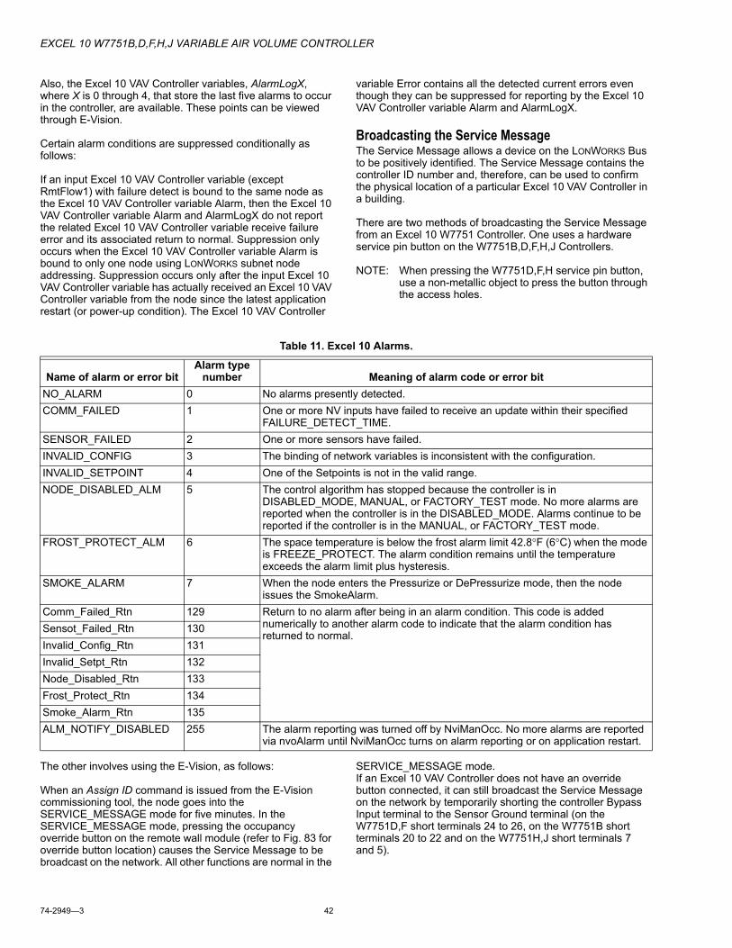
EXCEL 10 W7751B,D,F,H,J VARIABLE AIR VOLUME CONTROLLER
74-2949—3 42
Also, the Excel 10 VAV Controller variables, AlarmLogX, where X is 0 through 4, that store the last five alarms to occur in the controller, are available. These points can be viewed through E-Vision.
Certain alarm conditions are suppressed conditionally as follows:
If an input Excel 10 VAV Controller variable (except RmtFlow1) with failure detect is bound to the same node as the Excel 10 VAV Controller variable Alarm, then the Excel 10 VAV Controller variable Alarm and AlarmLogX do not report the related Excel 10 VAV Controller variable receive failure error and its associated return to normal. Suppression only occurs when the Excel 10 VAV Controller variable Alarm is bound to only one node using LONWORKS subnet node addressing. Suppression occurs only after the input Excel 10 VAV Controller variable has actually received an Excel 10 VAV Controller variable from the node since the latest application restart (or power-up condition). The Excel 10 VAV Controller
variable Error contains all the detected current errors even though they can be suppressed for reporting by the Excel 10 VAV Controller variable Alarm and AlarmLogX.
Broadcasting the Service MessageThe Service Message allows a device on the LONWORKS Bus to be positively identified. The Service Message contains the controller ID number and, therefore, can be used to confirm the physical location of a particular Excel 10 VAV Controller in a building.
There are two methods of broadcasting the Service Message from an Excel 10 W7751 Controller. One uses a hardware service pin button on the W7751B,D,F,H,J Controllers.
NOTE: When pressing the W7751D,F,H service pin button, use a non-metallic object to press the button through the access holes.
The other involves using the E-Vision, as follows:
When an Assign ID command is issued from the E-Vision commissioning tool, the node goes into the SERVICE_MESSAGE mode for five minutes. In the SERVICE_MESSAGE mode, pressing the occupancy override button on the remote wall module (refer to Fig. 83 for override button location) causes the Service Message to be broadcast on the network. All other functions are normal in the
SERVICE_MESSAGE mode. If an Excel 10 VAV Controller does not have an override button connected, it can still broadcast the Service Message on the network by temporarily shorting the controller Bypass Input terminal to the Sensor Ground terminal (on the W7751D,F short terminals 24 to 26, on the W7751B short terminals 20 to 22 and on the W7751H,J short terminals 7 and 5).
Table 11. Excel 10 Alarms.
Name of alarm or error bitAlarm type
number Meaning of alarm code or error bitNO_ALARM 0 No alarms presently detected.COMM_FAILED 1 One or more NV inputs have failed to receive an update within their specified
FAILURE_DETECT_TIME.SENSOR_FAILED 2 One or more sensors have failed.INVALID_CONFIG 3 The binding of network variables is inconsistent with the configuration.INVALID_SETPOINT 4 One of the Setpoints is not in the valid range.NODE_DISABLED_ALM 5 The control algorithm has stopped because the controller is in
DISABLED_MODE, MANUAL, or FACTORY_TEST mode. No more alarms are reported when the controller is in the DISABLED_MODE. Alarms continue to be reported if the controller is in the MANUAL, or FACTORY_TEST mode.
FROST_PROTECT_ALM 6 The space temperature is below the frost alarm limit 42.8°F (6°C) when the mode is FREEZE_PROTECT. The alarm condition remains until the temperature exceeds the alarm limit plus hysteresis.
SMOKE_ALARM 7 When the node enters the Pressurize or DePressurize mode, then the node issues the SmokeAlarm.
Comm_Failed_Rtn 129 Return to no alarm after being in an alarm condition. This code is added numerically to another alarm code to indicate that the alarm condition has returned to normal.
Sensot_Failed_Rtn 130Invalid_Config_Rtn 131Invalid_Setpt_Rtn 132Node_Disabled_Rtn 133Frost_Protect_Rtn 134Smoke_Alarm_Rtn 135ALM_NOTIFY_DISABLED 255 The alarm reporting was turned off by NviManOcc. No more alarms are reported
via nvoAlarm until NviManOcc turns on alarm reporting or on application restart.
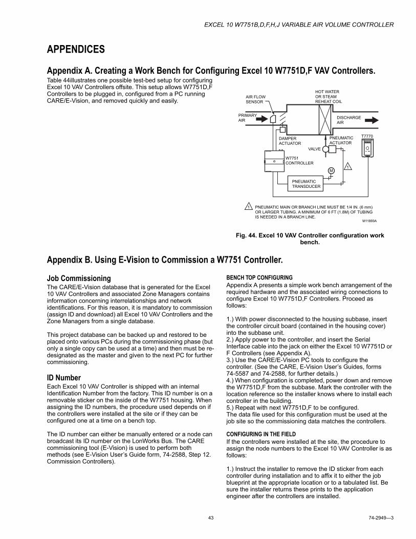
EXCEL 10 W7751B,D,F,H,J VARIABLE AIR VOLUME CONTROLLER
43 74-2949—3
APPENDICES
Appendix A. Creating a Work Bench for Configuring Excel 10 W7751D,F VAV Controllers.Table 44illustrates one possible test-bed setup for configuring Excel 10 VAV Controllers offsite. This setup allows W7751D,F Controllers to be plugged in, configured from a PC running CARE/E-Vision, and removed quickly and easily.
Fig. 44. Excel 10 VAV Controller configuration work bench.
Appendix B. Using E-Vision to Commission a W7751 Controller.
Job CommissioningThe CARE/E-Vision database that is generated for the Excel 10 VAV Controllers and associated Zone Managers contains information concerning interrelationships and network identifications. For this reason, it is mandatory to commission (assign ID and download) all Excel 10 VAV Controllers and the Zone Managers from a single database.
This project database can be backed up and restored to be placed onto various PCs during the commissioning phase (but only a single copy can be used at a time) and then must be re-designated as the master and given to the next PC for further commissioning.
ID NumberEach Excel 10 VAV Controller is shipped with an internal Identification Number from the factory. This ID number is on a removable sticker on the inside of the W7751 housing. When assigning the ID numbers, the procedure used depends on if the controllers were installed at the site or if they can be configured one at a time on a bench top.
The ID number can either be manually entered or a node can broadcast its ID number on the LonWorks Bus. The CARE commissioning tool (E-Vision) is used to perform both methods (see E-Vision User’s Guide form, 74-2588, Step 12. Commission Controllers).
BENCH TOP CONFIGURINGAppendix A presents a simple work bench arrangement of the required hardware and the associated wiring connections to configure Excel 10 W7751D,F Controllers. Proceed as follows:
1.) With power disconnected to the housing subbase, insert the controller circuit board (contained in the housing cover) into the subbase unit.2.) Apply power to the controller, and insert the Serial Interface cable into the jack on either the Excel 10 W7751D or F Controllers (see Appendix A).3.) Use the CARE/E-Vision PC tools to configure the controller. (See the CARE, E-Vision User’s Guides, forms 74-5587 and 74-2588, for further details.)4.) When configuration is completed, power down and remove the W7751D,F from the subbase. Mark the controller with the location reference so the installer knows where to install each controller in the building.5.) Repeat with next W7751D,F to be configured.The data file used for this configuration must be used at the job site so the commissioning data matches the controllers.
CONFIGURING IN THE FIELDIf the controllers were installed at the site, the procedure to assign the node numbers to the Excel 10 VAV Controller is as follows:
1.) Instruct the installer to remove the ID sticker from each controller during installation and to affix it to either the job blueprint at the appropriate location or to a tabulated list. Be sure the installer returns these prints to the application engineer after the controllers are installed.
M11869A
AIR FLOW
SENSOR
PRIMARY
AIR
DAMPER
ACTUATOR
HOT WATER
OR STEAM
REHEAT COIL
DISCHARGE
AIR
VALVE
W7751
CONTROLLER
PNEUMATIC
ACTUATOR
PNEUMATIC
TRANSDUCER
M
1
1
PNEUMATIC MAIN OR BRANCH LINE MUST BE 1/4 IN. (6 mm)
OR LARGER TUBING. A MINIMUM OF 6 FT (1.8M) OF TUBING
IS NEEDED IN A BRANCH LINE.
T7770
EXCEL 10 W7751B,D,F,H,J VARIABLE AIR VOLUME CONTROLLER
74-2949—3 44
2.) Connect to the LonWorks Bus with the CARE PC tool.
Proceed to configure the W7751 (using the job prints for location reference for the controllers) by following the standard CARE procedures.
CONFIGURING THE ZONE MANAGERThe Q7750A Excel 10 Zone Manager sends out a onetime LonWorks® message containing its 48-bit Neuron ID after any power-up WARMSTART or when the Excel 10 Zone Manager is reset by pressing the reset button.
IMPORTANTPressing the reset button on the Excel 10 Zone Man-ager causes all application files in the Q7751, includ-ing the C-Bus setup, to be lost.
The LonWorks® message is sent out one time and only on the E-Bus, not on the B-Port. The message will be the same as the one generated after pressing the service pin pushbutton available on Excel 10 VAV Controllers and also via the wall module bypass pushbutton. The CARE commissioning tool (E-Vision) can use this message to assign the node address.
The Assign ID procedure is the same as for an Excel 10 VAV Controller except, instead of pressing the bypass button, the reset button must be pressed or the power must be cycled (down then up) on the Q7750A Excel 10 Zone Manager.
Sensor CalibrationThe space temperature and the optional resistive inputs can all be calibrated. The wall module setpoint potentiometer can not be calibrated. Perform the sensor calibration by adding an offset value (either positive or negative) to the sensed value using E-Vision menus (see E-Vision user’s guide, form number 74-2588).
The temperature sensor in the Excel 10 wall modules can be calibrated to correct for sensor inaccuracies, wire resistance, etc. This allows the Excel 10 VAV Controller to sense the space temperature with a high degree of accuracy by applying a correction to the sensor input.
PROCEDURESelect the controller being worked on with E-Vision by right-clicking a controller on the subnet in the workspace and selecting Calibration from the menu (see the E-Vision User Guide for details on using E-Vision).
The calibration screen provides a list of sensors. After selecting a sensor, the actual value of the sensor displays. Enter the measured value that represents the true value that the sensor should be detecting. Click the Calibrate button to store the offset value in the controller.
Air Flow Balancing (For Pressure Independent applications only)In addition to the ten point Flow Pickup Calibration Table, the Excel 10 VAV Controller provides for 3-point (Maximum, Minimum, and Zero) Air Flow Calibration. This allows the box to be adjusted so it can be certified that the box provides the flow rates specified by the consulting engineer. When balancing is complete, the actual flow from a box should be within 5 to 10 percent of the indicated air flow (as shown on the E-Vision screen).
NOTE: There are many sources of error in flow-hood mea-surements. Flow hood meters typically attain accu-racy to within plus or minus three to five percent of full flow. The error can be due to the device being out of calibration, or that it was last calibrated with a dif-ferent style of diffuser. Even the operator technique plays a role in obtaining repeatable, accurate flow readings. When working with slotted diffusers, do not use a hood; use a velocity-probe type of instrument. Follow the diffuser manufacturer’s recommendation for how to best measure the air flow through their products.
PROCEDURE
CAUTION Prior to air flow balancing for the first time, perform a zero flow calibration procedure. To do so, power the Excel 10 VAV Controller for one hour or more before performing the procedure.
Select the controller being worked on with E-Vision (see the E-Vision User’s Guide, form 74-2588, for general details on using E-Vision). Due to inconsistencies in VGA display cards and modes, be sure to maximize the E-Vision window on the screen (by clicking the up-arrow at the top-right corner of the E-Vision window). This assures that all E-Vision activities are user viewable.
Using E-Vision and with the controller on-line, right click on the VAVII controller in the subnet area and select the Calibrate option. The Excel 10 VAVII calibration allows for both temperature and flow calibration. Click on the Air Flow Cal selection for Flow Calibration within the Sensor Calibration screen for VAVII. For specifics, please refer to the E-Vision User’s Guide, form 74-2588 to set the flow calibration for maximum, minimum, zero, and setpoint values.
RESETTING AIR FLOW CALIBRATION TO FACTORY DEFAULTSSelect the Action button titled “Reset” on the Air Flow Calibration Screen to reset to factory defaults.
VAVII Calibration SequenceTo calibrate a dual duct VAV box that has flow mixing with constant volume using two W7751 Controllers, follow the procedure shown below.
1. Create the Master controller in E-Vision.a. Add a VAVII controller to the network. Name the same
as the CARE name if using a Zone Manager.b. Configure the inputs and the outputs through the
Application Selection under the Controller menu.1.) Configuration Tab:
a.) Select the controller type (Standard, Smart, OEM).
b.) Select the Box Type (Dual_Duct).c.) Select the Flow Type (Master_Const_Flow).d.) Select the Pressure Type
(Press_Independent).e.) Select the Wall Module Type.f.) The Reheat Type will be DualDuctReheat, the
Fan Type will be NO_Fan and Morning Warm-up Type will be Fixed_Flow_Spt.
EXCEL 10 W7751B,D,F,H,J VARIABLE AIR VOLUME CONTROLLER
45 74-2949—3
2). Input Tab:a.) Select the Remote Stpt (Absolute_Setpoint,
Relative_Setpoint).b.) Select any additional Analog or Digital inputs.
3). Output Tab:a.) Enter the correct motor speed value (default is
90 seconds).b.) Verify that the direction to open the damper is
correct (default is CW).4). Cntrl Parameters Tab:
a.) Enter the desired Flow Setpoints.b.) Enter the correct Duct area or select the duct
diameter from the drop-down list.5). Flow Pickup Table Tab:
a.) Select the correct Flow Pickup from the Sensor Type drop-down list.
c. Click on the OK button to save the changes and exit out of the Application Selection screen.
2. Create the Satellite controller in E-Vision.a. Add a VAVII controller to the network. Name it the
same as the CARE name if using a Zone Manager.b. Configure the inputs and the outputs through Applica-
tion Selection under the Controller menu.1.) Configuration Tab:
a.) Select the controller type (Standard, Smart, OEM).
b.) Select the Box Type (Dual_Duct).c.) Select the Flow Type (Master_Const_Flow).d.) Select the Pressure Type
(Press_Independent).e.) Select the Wall Module Type.f.) The Reheat Type will be DualDuctReheat, the
Fan Type will be NO_Fan and Morning Warm-up Type will be Fixed_Flow_Spt.
2). Input Tab:a.) There will be no Remote Stpt for the Satellite
controller.b.) Select any additional Analog or Digital inputs.
3). Output Tab:a.) Enter the correct motor speed value (default is
90 seconds).b.) Verify that the direction to open the damper is
correct (default is CW).4). Cntrl Parameters Tab:
a.) Enter the desired Flow Setpoints. They should be the same as the Master controller setpoints.
b.) Enter the correct Duct area or select the duct diameter from the drop-down list.
c.) There are no Cooling or Heating Setpoints or Remote Setpoint limits available for the Satel-lite controller.
5). Flow Pickup Table Tab:a.) Select the correct Flow Pickup from the Sensor
Type drop-down list.c. Click on the OK button to save the changes and exit
out of the Application Selection screen.d. Bind the Wall Module from the Master controller to the
Satellite controller and the Satellite box flow to the Master controller.
1.) Select Refer Excel 10 Points (Network Menu item -Offline).
2). Select the Master controller to be the Source Excel 10.
3). Select the Satellite controller to be the Destination Excel 10.
4). Under Source Excel 10 Points, select SrcMaster.5). Under Destination Excel 10 Points, select Dest-
Satellite.6). Click on the Add button to add the binding to the
References list box.7). Select the Satellite controller to be the Source
Excel 10.8). Select the Master controller to be the Destination
Excel 10.9). Under Source Excel 10 Points, select SrcBox-
Flow.10).Under Destination Excel 10 Points, select Dest-
FlowTrack.11).Click on the Add button to add the binding to the
References list box. This will complete the binding that is required between the Master and the Satel-lite controllers. Click the Close button to exit the Refer Excel 10 Points dialog box.
3. Commission the Master and the Satellite Controllers.a. Select both controllers by clicking once on the Master
controller, then hold down the Ctrl key on the key-board and click on the Satellite controller.
b. Go to the Online mode (View menu item).c. Select Assign Neuron ID (Controller menu item). Use
the wall module Pushbutton on the Master controller wall module to assign the ID for the Master or manu-ally enter the ID for both the Master and the Satellite controllers. The status for both controllers should be Not Commissioned. Close out the dialog box.
d. Select Commission (Controller menu item). Both con-trollers should be listed in the list box and highlighted. Click on the Start button to commission the control-lers. Close out the dialog box after both controllers are commissioned.
e. Double click on the Master controller to bring up the Application Selection screen and select the Flow Pickup Table Tab.
f. Click on the Calculate button (this will create a new flow table based on the factory calibration values that were uploaded from the controller). A message box will display Flow Table Calculations Finished. Press Set or OK to complete. Click on the OK button to close the message box and then click the OK button to update the controller with the new values.
g. Repeat steps 3e and 3f for the Satellite controller.
4. Calibrate Air Flow.a. To calibrate the Master controller - Select the Master
controller (Cold Duct Damper).b. Select Calibration (Controller menu item) and
Air_Flow_Cal from the VAVII Sensor Calibration list box and then click on the Select button.
c. Select the Reset button to load the factory defaults (this is done so the controller has good starting values for the zero, minimum, and maximum calibration.
EXCEL 10 W7751B,D,F,H,J VARIABLE AIR VOLUME CONTROLLER
74-2949—3 46
d. Select the Zero button to do the Zero Calibration (this process will take a couple of minutes to complete). When calibration is complete, close the Air Flow Zero Calibration dialog box.
e. Select the Maximum button to do the maximum cali-bration. When Maximum Calibration Status displays Setpoint reached, enter measured flow, then enter the measured value and click on the Calibrate button. When calibration is complete, close the Air Flow Max-imum Calibration dialog box.
f. Select the Minimum button to do the minimum cali-bration. When Minimum Calibration Status displays Setpoint reached, enter measured flow, then enter the measured value and click on the Calibrate button. When calibration is complete, close the Air Flow Mini-mum Calibration dialog box.
g. Close the Air Flow Calibration and the VAVII Sensor Calibration dialog boxes.
h. Select the Satellite controller (Hot Duct Damper).i. To balance the Hot Duct Damper, the Cold Duct
Damper has to be closed. This example will use the Hand Held Tool (HHT) to command the Cold Duct Damper closed. The following steps will guide the user to manually command the damper closed.1.) Plug the HHT into the Master controllers wall
module or the Master controller and turn on the power switch. The HHT software version number will be displayed (it should be 01.01.02 or greater).
2). Press Enter to get to the main menu. Scroll down to HHT Functions and hit the Enter key.
3). Scroll down to Change Authorization and hit the Enter key.
4). Scroll down to Operator Level and hit the Enter key. For new level, enter level 4.
5). Enter the Password for that level and hit the Enter key. Hit the Prev Menu button a number of times to get back to the VAV2 Main Menu.
6). Pick the Select Excel 10 menu item and hit the Enter key. Scroll down to Push Button ID and hit the Enter key.
7). The HHT will prompt the user to press the push-button on the Master controllers wall module. The next screen will display Excel 10 Selected and also display the Nodes ID number.
8). Press any key to go to the VAV2 Main Menu. Scroll down to Service Excel 10 and press the Enter key.
9). Scroll down to I/O Points and press the Enter key.10).Scroll down to Commandable Points and press
the Enter key.11).Scroll down to Manual Damper/Flow and press
the Enter key.12).Use the Left or Right arrows to select Position on
the bottom line (default is Null). For New Position enter a value of 0 and press the Enter key. The Cold Duct Damper will be driven closed. The dis-play will show the current position of the damper. The ReFresh key will have to be pressed to update the current position. When the damper position displays 0, the user can go to step 4j to calibrate the Satellite controller (Hot Duct Damper).
j. To calibrate the Satellite controller, repeat steps 4b through 4g.
k. Press the Prev Menu key on the HHT. The HHT will display Manual Damper Leave Fixed?. Select No and press the Enter key to put the damper back under automatic control.
l. Press the Prev Menu key a number of times to get back to the VAV2 Main Menu and select the Logout VAV2 menu item and press the Enter key.
5. Verify Calibration.a. Select the Master controller (Online Mode).b. Select the Monitor mode (Controller menu item).c. Verify the Cold/Hot Duct Flow values and if the VAV
box is reaching setpoints.
Appendix C. Sequences of Operation.This Appendix provides the control sequences of operation that are pressure independent or pressure dependent. In pressure dependent applications, the reheat setpoint will default from CFM (m3h) to a fixed percent open position for the damper.
NOTE: Pressure dependent applications require physical minimum and maximum position stops on the damper actuator.
Common Operations.The Excel 10 VAV temperature control applications have common configuration options. However, Exhaust Flow Tracking, does not perform temperature control at all, and is strictly a flow control algorithm; therefore, it does not share the common operations. This section describes the common operations.
Each application can have any or all of these devices configured with the restriction that every Excel 10 VAV Controller that controls temperature must have a temperature sensor (either wired directly to the controller or shared from another Excel 10 VAV Controller).
ROOM TEMPERATURE SENSOR (RMTEMP)This is the room space temperature sensor. This sensor is the T7770 Wall Module or the T7780 DDWM. When it is configured, it provides the temperature input for the W7751 temperature control loop. If it is not configured, it is required that a room temperature sensor value be transmitted from another LonWorks Bus device like the T7780 DDWM. If no valid room temperature value is available to the W7751 Controller, the temperature control algorithm in the controller is disabled, causing the heating and cooling control outputs to be turned off.
It can be required that either Wall Module or Room Temperature sharing be provided from another Excel 10 VAV Controller with a wall module or temperature sensor.
EXCEL 10 W7751B,D,F,H,J VARIABLE AIR VOLUME CONTROLLER
47 74-2949—3
The room temperature sensor can be calibrated via E-Vision (see Temperature Sensor Calibration in Appendix B).
REMOTE SETPOINT NOTE:The C7770A Air Temperature Sensor (DischargeAir_Sensor or Supply_Air_Sensor) or the setpoint pot options are selectable in E-Vision. (Either one or the other can be selected, but not both on the W7751H,J controller.)
This is the Setpoint Potentiometer contained in the T7770 Wall Module. When configured, this occupant value is set to calculate the actual cooling or heating Occupied Setpoint. There are two options for how to calculate the actual setpoint to be used by the temperature control algorithm: (Offset) and (Absolute Middle). When SetPtKnob is set to Offset, the Wall Module setpoint knob represents a number from -5° to +5°C (-9° to +9°F) which is added to the software occupied setpoints for the heat and the cool modes (CoolOccSpt and HeatOccSpt). When SetPtKnob is set to Absolute Middle, the setpoint knob becomes the center of the Zero Energy Band (ZEB) between the cooling and heating occupied setpoints. The size of the ZEB is found by taking the difference between the software heating and cooling occupied setpoints; therefore, for Absolute Middle, the actual setpoints are found as follows:
RmTempActSpt (in cooling mode) = RmtStptPot + (CoolOccSpt - HeatOccSpt) / 2
RmTempActSpt (in reheat mode) = RmtStptPot - (CoolOccSpt - HeatOccSpt) / 2
During Standby and Unoccupied times, the remote setpoint pot is not referenced, and the software setpoints for those modes are used instead.
The C7770A Air Temperature Sensor is a direct-wired temperature sensor that is used to sense discharge, supply or return air in a duct that can be controlled by an Excel 10 W7751 VAV Controller. When configured, this provides the temperature input for the VAV controller setpoint inputs.
SETPOINT LIMITS (STPTLOLIM AND STPTHILIM)Remote setpoint pot limits are provided by StptLoLim and StptHiLim. The occupied setpoints used in the control algorithms are limited by these parameters. When the setpoint knob is configured to be of type Absolute Middle, the lowest actual setpoint allowed is equal to StptLoLim, and the highest actual setpoint allowed is equal to StptHiLim. When the setpoint knob is configured to be an Offset type, the lowest actual setpoint allowed is equal to HeatOccSpt - StptLoLim, and the highest allowed is equal to CoolOccSpt + StptHiLim.
BYPASS MODE (STATUSOVRRIDE AND STATUSLED)During Unoccupied periods, the facility occupant can request that Occupied temperature control setpoints be observed by depressing the Bypass pushbutton on the wall module. When activated, the controller remains in Bypass mode until:
1. Bypass Duration Setting has timed out (BypassTime), or2. User again presses the Wall Module pushbutton to
switch off Bypass mode, or3. Occupancy schedule (NviTodEvent network input)
switches the mode to Occupied.4. User sets the DestManualOcc network point to Not
Assigned.
The LED on the Wall Module (StatusLed) indicates the current bypass mode status (see the T7770C,D Wall Module Override LED section).
BYPASSTIMEBypassTime is the time between the pressing of the override button at the wall module (or initiating OC_BYPASS via DestManualOcc) and the return to the original occupancy state. When the bypass state has been activated, the bypass timer is set to BypassTime (default of 180 minutes).
OVERRIDETYPEOverrideType specifies the behavior of the override button on the wall module. There are two possible states that have the following meanings:
Bypass_UnOcc-Causes the override button to set the Override state to OC_BYPASS for BypassTime (default 180 minutes), when the override button has been pressed for approximately 1 to 4 seconds, or to set the override state to UNOCC when the button has been pressed for approximately 4 to 7 seconds. When the button is pressed longer than approximately 7 seconds, then the override state is set to OC_NUL (no manual override is active).
Only_Bypass-causes the override button to set the override state to OC_BYPASS for BypassTime (default 180 minutes), on the first press (1 to 7 seconds). On the next press, the override state is set to OC_NUL (no manual over ride is active).
OVERRIDE PRIORITYOverride Priority configures the override arbitration between DestManualOcc, DestBypassState, and the wall module override button. There are two possible states which have the following meanings:
LAST (Last_Cmd) -Specifies that the last command received from either the wall module or DestManualOcc determines the effective override state.
NET (ManOcc_Cmd) -Specifies that when DestManualOcc is not OC_NUL, then the effective occupancy is Dest-ManualOcc regardless of the wall module override state.
STANDBY MODEThe digital input for an occupancy sensor (usually a motion detector, or can be a time clock) provides the controller with a means to enter an energy-saving Standby mode whenever there are no people in the room. Standby mode occurs when the scheduled occupancy is Occupied, and the occupancy sensor detects no people currently in the room (digital input contacts Closed means people are in the room, and contacts Open means the room is Unoccupied). When in Standby mode, the Excel 10 VAV Controller uses the Standby Cooling (or Heating) Setpoint (CoolStbySpt or HeatStbySpt) for the Actual Space Temperature Setpoint.
WINDOW SENSORThe digital input for a window contact provides the algorithm with a means to disable its temperature control activities if someone has opened a window or door in the room. When a window is detected to be Open (digital input contacts Open equals window open), the box damper is commanded to control a damper to a configured percentage of maximum
EXCEL 10 W7751B,D,F,H,J VARIABLE AIR VOLUME CONTROLLER
74-2949—3 48
CFM (m3h) air flow for the ZeroDmprPos setting. Normal temperature control resumes when the window or door closes.
CAV CONTROLOn the occasion where it is required to supply Constant Air Volume (CAV) to the space, applications 1 through 15, can be used by assigning Maximum and Minimum and Reheat Air Flow Setpoints to the same value.
CONTINUOUS UNOCCUPIED MODEThis mode is entered when a wall module is configured with a bypass button (Type Bypass_UnOcc) that was pressed for four to seven seconds, causing the wall module LED to blink. This mode can also be entered via a network command (ManualOcc set to Unoccupied). If the controller is in this mode, it reverts to the Unoccupied Setpoints and control. The controller remains in this mode indefinitely or until the bypass button is pressed to exit the mode or a network command is sent to clear the mode.
SHARE WALL MODULEIf one or more terminal units serve a common area, and it is specified (or desired) to use a single temperature sensor for these boxes, the Share Wall Module option can be configured. Refer to the Cautions and Notes in the Wall Module Options section, Common Temperature Control (Shared Wall Module subsection).
The operation of the satellite controllers follows the temperature control and modes of the controller with the temperature sensor module. For example, this includes Temperature Setpoints and Occupied/Unoccupied/Standby/Bypass, modes. Each satellite controller performs flow loop control with its own Maximum, Minimum and Reheat Flow Setpoints, but is directed by the primary controller. For example, if the primary control is at 50 percent of flow; that is, 500 CFM (849 m3h) for MAX/MIN values of 1000/0 CFM (1700/0 m3h), then the satellite is also at 50 percent of its own Flow Setpoints, such as 400 CFM (680 m3h) for MAX/MIN values of 800/0 CFM (1360/0 m3h). Similarly, the primary unit directs the percent open or number of heating stages on for the satellite units.
NIGHT PURGEIf a terminal unit is put into the Night Purge mode via program (or manual) control, CmdMode set to (Night Purge), the controller performs the following functions (It):
• Disables the temperature control loop.• Disables the flow control loop.• Controls a damper to a configured percentage of maximum
CFM (m3h) air flow (PurgeDmprPos).• Enables terminal fan.
MORNING WARM-UPA Morning Warm-Up cycle commands the Excel 10 VAV Controller to open its VAV box to a preselected position to allow the conditioned space to warm up. (On boxes with reheat, the reheat is locked out during the Warm-Up mode.) When Morning Warm-Up is completed, Excel 10 VAV Controllers are commanded to the Occupied condition.
If a unit is put into Morning Warm-Up mode via program (or manual) control, CmdMode set to (Morning Warm-Up), then the controller disables its temperature and flow loops and performs the following functions (It):• Controls a damper to a configured percentage of maximum
CFM (m3h) air flow (MornWarmupPos).• Enables terminal fan.• Disables local heat (staged or modulating).
SMOKE CONTROLThe Excel 10 VAV Controller supports two smoke-related modes, Pressurize, and Depressurize. When the controller is placed in one of these two modes via a network command, the box damper is commanded to a fixed position specified in a separate user-adjustable Setpoint for each mode, and the temperature control function is disabled.
DEMAND LIMIT CONTROLWhen a high-electrical-demand signal is received via the LonWorks Bus network, the controller applies a DlcBumpTemp Setpoint to the current PID error value. This has the effect of bumping the temperature control point to save energy. This offset bumps the cooling control point upward, and bumps the heating control point downward.
START-UPUpon initial start-up or on a restart after power failure, the Excel 10 VAV Controller neuron ID number is used as a random number that assigns the controller to one of two groups, even or odd. Based on this determination, one group of controllers drives its actuators open and the other group drives its actuators closed. Only on initial power-up can a controller drive its actuators to go open. Controllers in these groups go through a controlled restart with different time delays to assure smooth air handling unit start-up, minimizing air distribution problems.
NOTE: After a controller download via E-Vision, the delayed reset time is bypassed and the controller starts after a 40-second initialization.
AIR FLOW CONTROL SEQUENCES OF OPERATIONThe primary function of the temperature-control applications is to regulate the quantity in Meters Cubed per Hour or CFM, of supply air delivered to the space to control the space temperature. The algorithm assumes there is cold air in the duct; therefore, as the box damper is opened wider, the space becomes cooler.
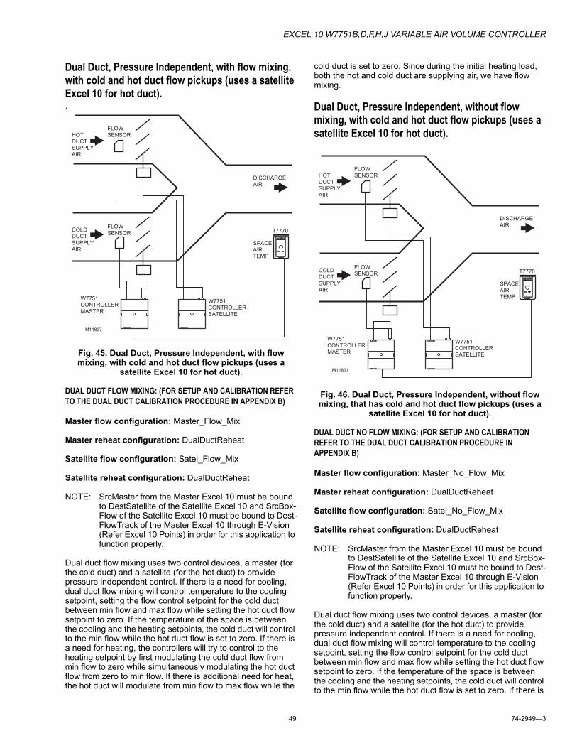
EXCEL 10 W7751B,D,F,H,J VARIABLE AIR VOLUME CONTROLLER
49 74-2949—3
Dual Duct, Pressure Independent, with flow mixing, with cold and hot duct flow pickups (uses a satellite Excel 10 for hot duct)..
Fig. 45. Dual Duct, Pressure Independent, with flow mixing, with cold and hot duct flow pickups (uses a
satellite Excel 10 for hot duct).
DUAL DUCT FLOW MIXING: (FOR SETUP AND CALIBRATION REFER TO THE DUAL DUCT CALIBRATION PROCEDURE IN APPENDIX B)
Master flow configuration: Master_Flow_Mix
Master reheat configuration: DualDuctReheat
Satellite flow configuration: Satel_Flow_Mix
Satellite reheat configuration: DualDuctReheat
NOTE: SrcMaster from the Master Excel 10 must be bound to DestSatellite of the Satellite Excel 10 and SrcBox-Flow of the Satellite Excel 10 must be bound to Dest-FlowTrack of the Master Excel 10 through E-Vision (Refer Excel 10 Points) in order for this application to function properly.
Dual duct flow mixing uses two control devices, a master (for the cold duct) and a satellite (for the hot duct) to provide pressure independent control. If there is a need for cooling, dual duct flow mixing will control temperature to the cooling setpoint, setting the flow control setpoint for the cold duct between min flow and max flow while setting the hot duct flow setpoint to zero. If the temperature of the space is between the cooling and the heating setpoints, the cold duct will control to the min flow while the hot duct flow is set to zero. If there is a need for heating, the controllers will try to control to the heating setpoint by first modulating the cold duct flow from min flow to zero while simultaneously modulating the hot duct flow from zero to min flow. If there is additional need for heat, the hot duct will modulate from min flow to max flow while the
cold duct is set to zero. Since during the initial heating load, both the hot and cold duct are supplying air, we have flow mixing.
Dual Duct, Pressure Independent, without flow mixing, with cold and hot duct flow pickups (uses a satellite Excel 10 for hot duct).
Fig. 46. Dual Duct, Pressure Independent, without flow mixing, that has cold and hot duct flow pickups (uses a
satellite Excel 10 for hot duct).
DUAL DUCT NO FLOW MIXING: (FOR SETUP AND CALIBRATION REFER TO THE DUAL DUCT CALIBRATION PROCEDURE IN APPENDIX B)
Master flow configuration: Master_No_Flow_Mix
Master reheat configuration: DualDuctReheat
Satellite flow configuration: Satel_No_Flow_Mix
Satellite reheat configuration: DualDuctReheat
NOTE: SrcMaster from the Master Excel 10 must be bound to DestSatellite of the Satellite Excel 10 and SrcBox-Flow of the Satellite Excel 10 must be bound to Dest-FlowTrack of the Master Excel 10 through E-Vision (Refer Excel 10 Points) in order for this application to function properly.
Dual duct flow mixing uses two control devices, a master (for the cold duct) and a satellite (for the hot duct) to provide pressure independent control. If there is a need for cooling, dual duct flow mixing will control temperature to the cooling setpoint, setting the flow control setpoint for the cold duct between min flow and max flow while setting the hot duct flow setpoint to zero. If the temperature of the space is between the cooling and the heating setpoints, the cold duct will control to the min flow while the hot duct flow is set to zero. If there is
T7770
HOTDUCTSUPPLYAIR
COLDDUCTSUPPLYAIR
DISCHARGE AIR
FLOWSENSOR
FLOWSENSOR
W7751CONTROLLERMASTER
SPACEAIRTEMP
W7751CONTROLLERSATELLITE
M11837
T7770
HOTDUCTSUPPLYAIR
COLDDUCTSUPPLYAIR
DISCHARGE AIR
FLOWSENSOR
FLOWSENSOR
W7751CONTROLLERMASTER
SPACEAIRTEMP
W7751CONTROLLERSATELLITE
M11837
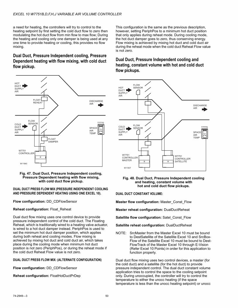
EXCEL 10 W7751B,D,F,H,J VARIABLE AIR VOLUME CONTROLLER
74-2949—3 50
a need for heating, the controllers will try to control to the heating setpoint by first setting the cold duct flow to zero then modulating the hot duct flow from min flow to max flow; During the heating and cooling only one damper is being used at any one time to provide heating or cooling, this provides no flow mixing.
Dual Duct, Pressure Independent cooling, Pressure Dependent heating with flow mixing, with cold duct flow pickup.
Fig. 47. Dual Duct, Pressure Independent cooling, Pressure Dependent heating with flow mixing,
with cold duct flow pickup.
DUAL DUCT PRESS FLOW MIX (PRESSURE INDEPENDENT COOLING AND PRESSURE DEPENDENT HEATING USING ONE EXCEL 10).
Flow configuration: DD_CDFlowSensor
Reheat configuration: Float_Reheat
Dual duct flow mixing uses one control device to provide pressure independent control of the cold duct. The Floating Reheat, which is traditionally wired to a heating valve actuator, is wired to a hot duct damper instead. PeriphPos is used to set the minimum hot duct damper position, which applies during both reheat and cooling modes. Flow mixing is achieved by mixing hot duct and cold duct air, which takes place during the cooling mode when minimum hot duct position is not zero (PeriphPos), or during the reheat mode if the cold duct Reheat Flow value is not zero.
DUAL DUCT PRESS FLOW MIX: (ALTERNATE CONFIGURATION)
Flow configuration: DD_CDFlowSensor
Reheat configuration: FloatHotDuctPrDep
This configuration is the same as the previous description, however, setting PeriphPos to a minimum hot duct position that only applies during reheat mode. During cooling mode, the hot duct damper goes to zero, thus conserving energy. Flow mixing is achieved by mixing hot duct and cold duct air during the reheat mode when the cold duct Reheat Flow value is not zero.
Dual Duct, Pressure Independent cooling and heating, constant volume with hot and cold duct flow pickups.
Fig. 48. Dual Duct, Pressure Independent cooling and heating, constant volume with
hot and cold duct flow pickups.
DUAL DUCT CONSTANT VOLUME:
Master flow configuration: Master_Const_Flow
Master reheat configuration: DualDuctReheat
Satellite flow configuration: Satel_Const_Flow
Satellite reheat configuration: DualDuctReheat
NOTE: SrcMaster from the Master Excel 10 must be bound to DestSatellite of the Satellite Excel 10 and SrcBox-Flow of the Satellite Excel 10 must be bound to Dest-FlowTrack of the Master Excel 10 through E-Vision (Refer Excel 10 Points) in order for this application to function properly.
Dual duct flow mixing uses two control devices, a master (for the cold duct) and a satellite (for the hot duct) to provide pressure independent control. The dual duct constant volume application tries to control the space to the cooling setpoint only. During unoccupied, the controller will try to control the temperature to either the unocc heating (if the space temperature is less than the unocc heating setpoint) or unocc
T7770
HOTDUCTSUPPLYAIR
COLDDUCTSUPPLYAIR
DISCHARGE AIR
FLOWSENSOR
W7751CONTROLLER
SPACEAIRTEMP
M11840
FLOATREHEAT
FLOATDAMPER
T7770
HOTDUCTSUPPLYAIR
COLDDUCTSUPPLYAIR
DISCHARGE AIR
FLOWSENSOR
FLOWSENSOR
W7751CONTROLLERMASTER
SPACEAIRTEMP
W7751CONTROLLERSATELLITE
M11837
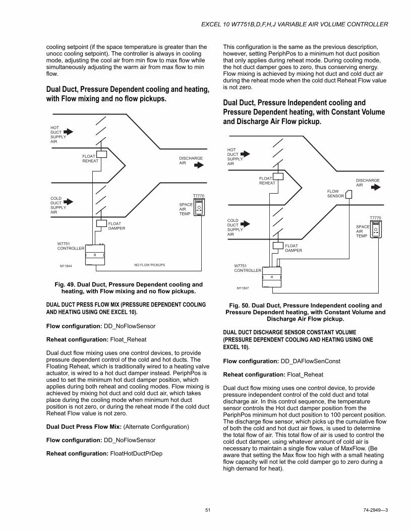
EXCEL 10 W7751B,D,F,H,J VARIABLE AIR VOLUME CONTROLLER
51 74-2949—3
cooling setpoint (if the space temperature is greater than the unocc cooling setpoint). The controller is always in cooling mode, adjusting the cool air from min flow to max flow while simultaneously adjusting the warm air from max flow to min flow.
Dual Duct, Pressure Dependent cooling and heating, with Flow mixing and no flow pickups.
Fig. 49. Dual Duct, Pressure Dependent cooling and heating, with Flow mixing and no flow pickups.
DUAL DUCT PRESS FLOW MIX (PRESSURE DEPENDENT COOLING AND HEATING USING ONE EXCEL 10).
Flow configuration: DD_NoFlowSensor
Reheat configuration: Float_Reheat
Dual duct flow mixing uses one control devices, to provide pressure dependent control of the cold and hot ducts. The Floating Reheat, which is traditionally wired to a heating valve actuator, is wired to a hot duct damper instead. PeriphPos is used to set the minimum hot duct damper position, which applies during both reheat and cooling modes. Flow mixing is achieved by mixing hot duct and cold duct air, which takes place during the cooling mode when minimum hot duct position is not zero, or during the reheat mode if the cold duct Reheat Flow value is not zero.
Dual Duct Press Flow Mix: (Alternate Configuration)
Flow configuration: DD_NoFlowSensor
Reheat configuration: FloatHotDuctPrDep
This configuration is the same as the previous description, however, setting PeriphPos to a minimum hot duct position that only applies during reheat mode. During cooling mode, the hot duct damper goes to zero, thus conserving energy. Flow mixing is achieved by mixing hot duct and cold duct air during the reheat mode when the cold duct Reheat Flow value is not zero.
Dual Duct, Pressure Independent cooling and Pressure Dependent heating, with Constant Volume and Discharge Air Flow pickup.
Fig. 50. Dual Duct, Pressure Independent cooling and Pressure Dependent heating, with Constant Volume and
Discharge Air Flow pickup.
DUAL DUCT DISCHARGE SENSOR CONSTANT VOLUME(PRESSURE DEPENDENT COOLING AND HEATING USING ONE EXCEL 10).
Flow configuration: DD_DAFlowSenConst
Reheat configuration: Float_Reheat
Dual duct flow mixing uses one control device, to provide pressure independent control of the cold duct and total discharge air. In this control sequence, the temperature sensor controls the Hot duct damper position from the PeriphPos minimum hot duct position to 100 percent position. The discharge flow sensor, which picks up the cumulative flow of both the cold and hot duct air flows, is used to determine the total flow of air. This total flow of air is used to control the cold duct damper, using whatever amount of cold air is necessary to maintain a single flow value of MaxFlow. (Be aware that setting the Max flow too high with a small heating flow capacity will not let the cold damper go to zero during a high demand for heat).
T7770
HOTDUCTSUPPLYAIR
COLDDUCTSUPPLYAIR
DISCHARGE AIR
W7751CONTROLLER
SPACEAIRTEMP
M11844
FLOATREHEAT
FLOATDAMPER
NO FLOW PICKUPS
T7770
HOTDUCTSUPPLYAIR
COLDDUCTSUPPLYAIR
DISCHARGE AIR
FLOWSENSOR
W7751CONTROLLER
SPACEAIRTEMP
M11847
FLOATREHEAT
FLOATDAMPER
EX
CE
L 10 W7751B
,D,F,H
,J VAR
IAB
LE A
IR VO
LUM
E C
ON
TRO
LLER
74-2949—3
52
Appendix D. Complete List of Excel 10 VAVII User AddressesTable 12. Input/Output Points.
User Address NvName Field Name
Engineering Units: English (Metric) or States plus Range
Digi
tal S
tate
or
Valu
e of S
tate
Default
E-Vi
siona
Shar
e
Map
Dire
ct A
cces
s
Hard
ware
Con
figur
atio
n
Manu
al Po
int
Test
CommentsRawTempSen1 nvoIO siTempSensorS7(0) degrees:
-9 to 122°F (-22.8 to 50°C)
255 SI_INVALID M X X RawTempSen1 reports the current sensor readings configured by TempInput1Type and TempInput2Type. NOTE: The reported temperature does not include the offset correction added during sensor calibration, TempInput1Cal or TempInput2Cal.
RawTempSen2 nvoIO siTempSensorS7(1) degrees: -9 to 122°F (-22.8 to 50°C)
SI_INVALID X RawTempSen2 reports the current sensor readings configured by TempInput1Type and TempInput2Type. NOTE: The reported temperature does not include the offset correction added during sensor calibration, TempInput1Cal or TempInput2Cal.
RawSpaceTemp nvoIO siSpaceTempS7 degrees: 40 to 100°F (4.4 to 37.8°C)
SI_INVALID X RawSpaceTemp is the measured space temperature. If the sensor is not configured or has failed, the value is SI_INVALID. NOTE: The reported temperatures does not include the offset correction SpaceTempCal.
RawFlowVolts nvoIO siFlowVoltsS12 Volts 0 to 6.5 SI_INVALID X RawFlowVolts is the on board flow sensor velocity measured by the A/D after pre-amplification and scaling. If a flow sensor error has been detected, RawFlowVolts set to SI_INVALID.
FlowUncorrected nvoIO siFlowUncorrectedS3 -300 to 3500 FPM (-1.5 to 17.5 m/s)
0 X FlowUncorrected is the air flow velocity measured by the on board flow sensor after zero correction and linearization. If a FlowError has been detected or ConfigPressDep (Press_Dependent in E-Vision) = TRUE, then FlowUncorrected is set to SI_INVALID.
FlowSensor nvoIO siFlowSensorS3 0 to 3500 FPM (0 to 17.5 m/s)
0 X X FlowSensor is the air flow velocity measured by the on-board flow sensor after zero calibration, linearization, and field corrections. If there is an error, then FlowSensor is set to SI_INVALID.
DigOutputByte nvoIO ubOut Byte Offset = 12 Bit Offset = 0 (DigitalOut1-8)
FALSETRUE
01
FALSE DigOutputByte - Bit Offset = 0 (DigitalOut1) DigOutputByte is a byte with a bit representing the state of every physical digital output.On is a 1 (TRUE) and off 0 (FALSE). (DigitalOut1 through DigitalOut8).
DigInputByte nvoIO ubDigitalIn Byte Offset = 13 Bit Offset = 7 (DigitalIn1-4)
FALSETRUE
01
FALSE DigInputByte Bit Offset = 7 (DigitalIn1): DigInputByte is a byte with a bit for every physical digital input. If the input is shorted to ground, the bit is a 0 or FALSE. If the input is open, the bit is 1 or TRUE. (DigitalIn1 through DigitalIn4).
a For E-Vision column: Calibrate (C), Monitor (M), Parameter (P), Schematic (S).
EX
CEL 10 W
7751B,D
,F,H,J VA
RIA
BLE
AIR
VOLU
ME
CO
NTR
OLLE
R
5374-2949—
3
OccupancySnsr nvoIO OccupancySensor FALSETRUE
01
FALSE M X X OccupancySnsr is the state of the digital input configured and wired to the local occupancy sensor. 1 means that occupancy is being sensed (input circuit shorted) and 0 means that no occupancy is being sensed (input circuit open).
WindowSensr nvoIO WindowOpen FALSETRUE
01
FALSE X WindowSensr is the state of the digital input configured and wired to a window open sensor switch. A 1 (input open circuit) means that the window is open, and 0 (input shorted) means that the window is closed.
HeatCoolCOSw nvoIO HeatCoolSwitch FALSETRUE
01
FALSE X HeatCoolCOSw is the state of the digital input configured and wired to a Heat/Cool change over switch. The state of HeatCoolCOSw is: FALSE (open): select Cool Mode TRUE (closed): select Heat Mode.
FreeDigInput nvoIO MonSwitch FALSETRUE
01
FALSE X FreeDigInput is the state of the digital input configured and wired to a general purpose monitor switch.1 (input shorted) means that switch is closed, and 0 (input open) means that the switch is open.
IOTestSwitch nvoIO IOTestSwitch FALSETRUE
01
FALSE IOTestSwitch is the state of the digital input configured and wired to a IO test The state of IOTestSwitch is: FALSE (open): Normal operation TRUE (closed): If Model is Large, perform stand-alone IO test.
OverrideInput nvoIO OverRide FALSETRUE
01
FALSE X OverrideInput indicates the status of the wall module override pushbutton. It is 1 (TRUE) if the button is pressed, and is 0 (FALSE) if it is not pressed.
Model nvoIO Model UNKNOWN_MODELSMALL_MODELMED_MODELLARGE_MODEL
0123
UNKNOWN_MODEL C Model: The hardware configuration is encoded as a resistor value connected to an analog resistive input. Model reports the detected hardware configuration. (SMALL_MODEL is the W7751H,J SmartVAV Actuator. LARGE_MODEL is the W7751D,F VAV Controllers and the W7751B OEM VAV Controller.)
RawData0 nvoIO raw_data(0) 0 to 65535 0 RawData0 represents the A/D counts from the analog inputs. The counts represent measured time during the second part of each A/D conversion cycle and can be used during testing of the A/D.
RawData1 nvoIO raw_data(1) 0 to 65535 0 MS
RawData1 represents the A/D counts from the analog inputs. The counts represent measured time during the second part of each A/D conversion cycle and can be used during testing of the A/D.
RawData2 nvoIO raw_data(2) 0 to 65535 0 RawData2 represents the A/D counts from the analog inputs. The counts represent measured time during the second part of each A/D conversion cycle and can be used during testing of the A/D.
Table 12. Input/Output Points. (Continued)
User Address NvName Field Name
Engineering Units: English (Metric) or States plus Range
Digi
tal S
tate
or
Valu
e of S
tate
Default
E-Vi
siona
Shar
e
Map
Dire
ct A
cces
s
Hard
ware
Con
figur
atio
n
Manu
al Po
int
Test
Comments
a For E-Vision column: Calibrate (C), Monitor (M), Parameter (P), Schematic (S).
EX
CE
L 10 W7751B
,D,F,H
,J VAR
IAB
LE A
IR VO
LUM
E C
ON
TRO
LLER
74-2949—3
54
RawData3 nvoIO raw_data(3) 0 to 65535 0 RawData3 represents the A/D counts from the analog inputs. The counts represent measured time during the second part of each A/D conversion cycle and can be used during testing of the A/D.
RawData4 nvoIO raw_data(4) 0 to 65535 0 RawData4 represents the A/D counts from the analog inputs. The counts represent measured time during the second part of each A/D conversion cycle and can be used during testing of the A/D.
RawData5 nvoIO raw_data(5) 0 to 65535 0 RawData5 represents the A/D counts from the analog inputs. The counts represent measured time during the second part of each A/D conversion cycle and can be used during testing of the A/D.
RawData6 nvoIO raw_data(6) 0 to 65535 0 RawData6 represents the A/D counts from the analog inputs. The counts represent measured time during the second part of each A/D conversion cycle and can be used during testing of the A/D.
RawData7 nvoIO raw_data(7) 0 to 65535 0 RawData7 represents the A/D counts from the analog inputs. The counts represent measured time during the second part of each A/D conversion cycle.
Table 12. Input/Output Points. (Continued)
User Address NvName Field Name
Engineering Units: English (Metric) or States plus Range
Digi
tal S
tate
or
Valu
e of S
tate
Default
E-Vi
siona
Shar
e
Map
Dire
ct A
cces
s
Hard
ware
Con
figur
atio
n
Manu
al Po
int
Test
Comments
a For E-Vision column: Calibrate (C), Monitor (M), Parameter (P), Schematic (S).
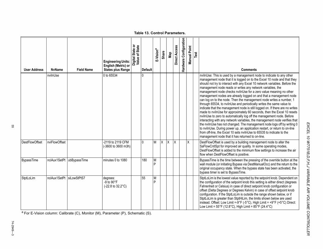
EX
CEL 10 W
7751B,D
,F,H,J VA
RIA
BLE
AIR
VOLU
ME
CO
NTR
OLLE
R
5574-2949—
3
Table 13. Control Parameters.
User Address NvName Field Name
Engineering Units: English (Metric) or States plus Range
Digi
tal S
tate
or
Valu
e of S
tate
Default
E-Vi
siona
Shar
e
Map
Dire
ct A
cces
s
Hard
ware
Con
figur
atio
n
Manu
al Po
int
Test
CommentsnviInUse 0 to 65534 0 nviInUse: This is used by a management node to indicate to any other
management node that it is logged on to the Excel 10 node and that they should not try to interact with any Excel 10 network variables. Before the management node reads or writes any network variables, the management node checks nviInUse for a zero value meaning no other management nodes are already logged on and that a management node can log on to the node. Then the management node writes a number, 1 through 65534, to nviInUse and periodically writes the same value to indicate that the management node is still logged on. If there are no writes made to nviInUse for approximately 60 seconds, then the Excel 10 resets nviInUse to zero to automatically log off the management node. Before interacting with any network variables, the management node verifies that the nviInUse has not changed. The management node logs off by writing 0 to nviInUse. During power up, an application restart, or return to on-line from off-line, the Excel 10 sets nviInUse to 65535 to indicate to the management node that it has returned to on-line.
DestFlowOffset nviFlowOffset -2119 to 2119 CFM (-3600 to 3600 m3h)
0 M X X X X DestFlowOffset is used by a building management node to alter the SaFlowCntlSpt for improved air quality. In some operating modes, DestFlowOffset is added to the minimum flow settings to increase the air flow when DestFlowOffset is positive.
BypassTime nciAux1SetPt ubBypassTime minutes 0 to 1080 180 MP
BypassTime is the time between the pressing of the override button at the wall module (or initiating Bypass via DestManualOcc) and the return to the original occupancy state. When the bypass state has been activated, the bypass timer is set to BypassTime.
StptLoLim nciAux1SetPt siLowStPtS7 degrees: -9 to 90°F (-22.8 to 32.2°C)
55 MP
StptLoLim is the lowest value reported by the setpoint knob. Dependent on the configuration of the setpoint knob this setting is either direct (degrees Fahrenheit or Celsius) in case of direct setpoint knob configuration or offset (Delta Degrees or Degrees Kelvin) in case of offset setpoint knob configuration. If the StptLoLim is outside the range shown below, or if StptLoLim is greater than StptHiLim, the limits shown below are used instead. Offset: Low Limit =-9°F (-5°C), High Limit = +9°F (+5°C) Direct: Low Limit = 55°F (12.8°C), High Limit = 85°F (24.4°C)
a For E-Vision column: Calibrate (C), Monitor (M), Parameter (P), Schematic (S).
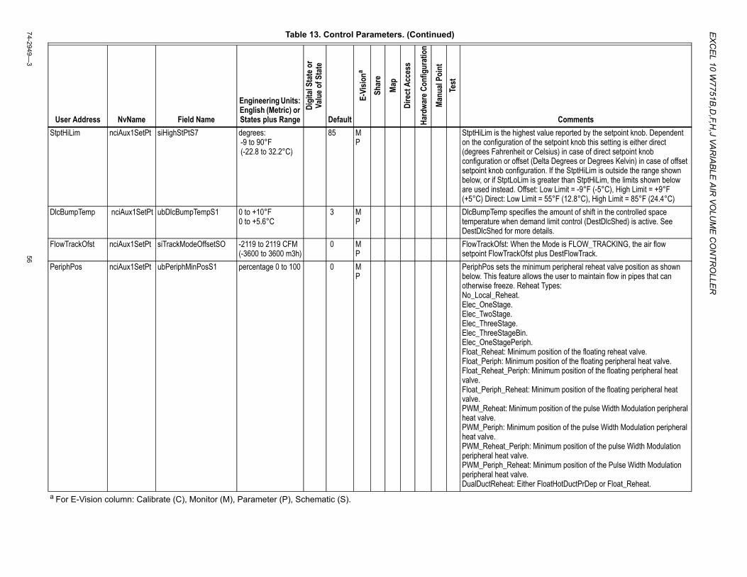
EX
CE
L 10 W7751B
,D,F,H
,J VAR
IAB
LE A
IR VO
LUM
E C
ON
TRO
LLER
74-2949—3
56
StptHiLim nciAux1SetPt siHighStPtS7 degrees: -9 to 90°F (-22.8 to 32.2°C)
85 MP
StptHiLim is the highest value reported by the setpoint knob. Dependent on the configuration of the setpoint knob this setting is either direct (degrees Fahrenheit or Celsius) in case of direct setpoint knob configuration or offset (Delta Degrees or Degrees Kelvin) in case of offset setpoint knob configuration. If the StptHiLim is outside the range shown below, or if StptLoLim is greater than StptHiLim, the limits shown below are used instead. Offset: Low Limit = -9°F (-5°C), High Limit = +9°F (+5°C) Direct: Low Limit = 55°F (12.8°C), High Limit = 85°F (24.4°C)
DlcBumpTemp nciAux1SetPt ubDlcBumpTempS1 0 to +10°F 0 to +5.6°C
3 MP
DlcBumpTemp specifies the amount of shift in the controlled space temperature when demand limit control (DestDlcShed) is active. See DestDlcShed for more details.
FlowTrackOfst nciAux1SetPt siTrackModeOffsetSO -2119 to 2119 CFM (-3600 to 3600 m3h)
0 MP
FlowTrackOfst: When the Mode is FLOW_TRACKING, the air flow setpoint FlowTrackOfst plus DestFlowTrack.
PeriphPos nciAux1SetPt ubPeriphMinPosS1 percentage 0 to 100 0 MP
PeriphPos sets the minimum peripheral reheat valve position as shown below. This feature allows the user to maintain flow in pipes that can otherwise freeze. Reheat Types:No_Local_Reheat.Elec_OneStage.Elec_TwoStage.Elec_ThreeStage.Elec_ThreeStageBin.Elec_OneStagePeriph.Float_Reheat: Minimum position of the floating reheat valve.Float_Periph: Minimum position of the floating peripheral heat valve.Float_Reheat_Periph: Minimum position of the floating peripheral heat valve.Float_Periph_Reheat: Minimum position of the floating peripheral heat valve.PWM_Reheat: Minimum position of the pulse Width Modulation peripheral heat valve.PWM_Periph: Minimum position of the pulse Width Modulation peripheral heat valve.PWM_Reheat_Periph: Minimum position of the pulse Width Modulation peripheral heat valve.PWM_Periph_Reheat: Minimum position of the Pulse Width Modulation peripheral heat valve.DualDuctReheat: Either FloatHotDuctPrDep or Float_Reheat.
Table 13. Control Parameters. (Continued)
User Address NvName Field Name
Engineering Units: English (Metric) or States plus Range
Digi
tal S
tate
or
Valu
e of S
tate
Default
E-Vi
siona
Shar
e
Map
Dire
ct A
cces
s
Hard
ware
Con
figur
atio
n
Manu
al Po
int
Test
Comments
a For E-Vision column: Calibrate (C), Monitor (M), Parameter (P), Schematic (S).
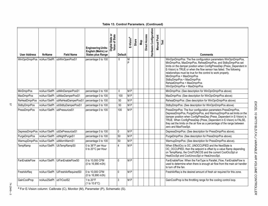
EX
CEL 10 W
7751B,D
,F,H,J VA
RIA
BLE
AIR
VOLU
ME
CO
NTR
OLLE
R
5774-2949—
3
WinOpnDmprPos nciAux1SetPt ubWinOpenPosS1 percentage 0 to 100 0 MP
WinOpnDmprPos: The five configuration parameters WinOpnDmprPos, MinDmprPos, MaxDmprPos, ReheatDmprPos, and StdbyDmprPos set limits on the damper position when ConfigPressDep (Press_Dependent in E-Vision) is TRUE or when the flow sensor has failed. The following relationships must be true for the control to work properly.MinDmprPos < MaxDmprPosStdbyDmprPos < MaxDmprPosReheatDmprPos < MaxDmprPosWinOpnDmprPos < MaxDmprPos
MinDmprPos nciAux1SetPt ubMinDamperPosS1 percentage 0 to 100 0 M P MinDmprPos: (See description for WinOpnDmprPos above)MaxDmprPos nciAux1SetPt ubMaxDamperPosS1 percentage 0 to 100 100 M P MaxDmprPos: (See description for WinOpnDmprPos above)ReHeatDmprPos nciAux1SetPt ubReHeatDamperPosS1 percentage 0 to 100 50 M P ReheatDmprPos: (See description for WinOpnDmprPos above)StdbyDmprPos nciAux1SetPt ubStdbyDamperPosS1 percentage 0 to 100 50 M P StdbyDmprPos: (See description for WinOpnDmprPos above)PressDmprPos nciAux1SetPt ubPressurizeS1 percentage 0 to 100 100 M P PressDmprPos: The four configuration parameters PressDmprPos,
DepressDmprPos, PurgeDmprPos, and WarmupDmprPos set limits on the damper position when ConfigPressDep (Press_Dependent in E-Vision) is TRUE. When ConfigPressDep (Press_Dependent in E-Vision) is FALSE, they set the limits on the air flow as a percentage of the range between zero and MaxFlowSpt.
DepressDmprPos nciAux1SetPt ubDePressurizeS1 percentage 0 to 100 0 M P DepressDmprPos: (See description for PressDmprPos above).PurgeDmprPos nciAux1SetPt ubNightPurgeS1 percentage 0 to 100 50 M P PurgeDmprPos: (See description for PressDmprPos above).WarmupDmprPos nciAux1SetPt ubMornWarmS1 percentage 0 to 100 50 M P WarmupDmprPos: (See description for PressDmprPos above).TempRamp nciAux1SetPt UbTempRampS0 0 to 36°F per Hour
0 to 20°C per Hour4 M P When EffectOcc is OC_UNOCCUPIED and the NextState is
OC_OCCUPIED, then the setpoint is offset by a value Ramp depending on TempRamp, the CmdTUNCOS and the current CoolOccSpt or HeatOccSpt and CoolUnoccSpt or HeaUnoccSpt.
FanEnableFlow nciAux1SetPt UiFanEnableFlowS0 0 to 10,000 CFM (0 to 16,990 m3h)
0 M P FanEnableFlow: When the FanType is Parallel_Flow, FanEnableFlow is used to determine when there is enough air flow from the main air handler to turn off the fan.
FreshAirReq nciAux1SetPt UiFreshAirRequiredS0 0 to 10,000 CFM (0 to 16,990 m3h)
0 M P FreshAirReq is the desired amount of fresh air required for this zone.
GainCoolProp nciAux2SetPt ubTrCoolS2 1 to 20°F (1 to 10.6°C)
3 M P GainCoolProp is the throttling range for the cooling control loop.
Table 13. Control Parameters. (Continued)
User Address NvName Field Name
Engineering Units: English (Metric) or States plus Range
Digi
tal S
tate
or
Valu
e of S
tate
Default
E-Vi
siona
Shar
e
Map
Dire
ct A
cces
s
Hard
ware
Con
figur
atio
n
Manu
al Po
int
Test
Comments
a For E-Vision column: Calibrate (C), Monitor (M), Parameter (P), Schematic (S).
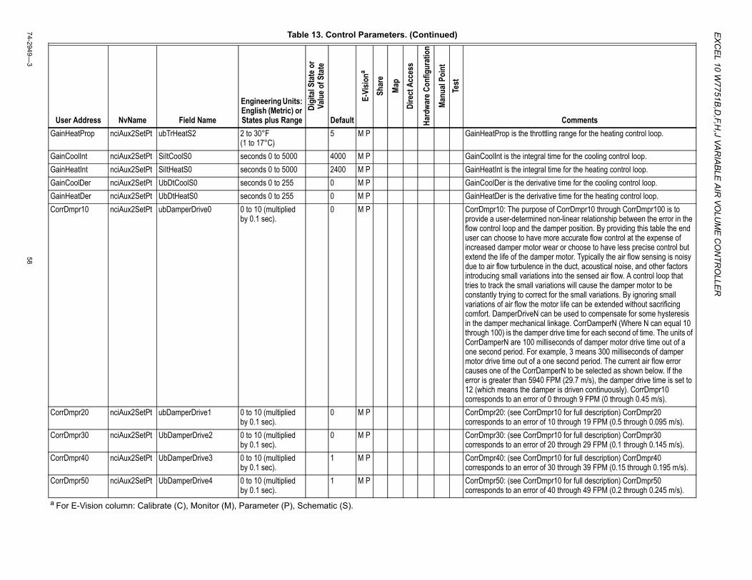
EX
CE
L 10 W7751B
,D,F,H
,J VAR
IAB
LE A
IR VO
LUM
E C
ON
TRO
LLER
74-2949—3
58
GainHeatProp nciAux2SetPt ubTrHeatS2 2 to 30°F (1 to 17°C)
5 M P GainHeatProp is the throttling range for the heating control loop.
GainCoolInt nciAux2SetPt SiItCoolS0 seconds 0 to 5000 4000 M P GainCoolInt is the integral time for the cooling control loop.GainHeatInt nciAux2SetPt SiItHeatS0 seconds 0 to 5000 2400 M P GainHeatInt is the integral time for the heating control loop.GainCoolDer nciAux2SetPt UbDtCoolS0 seconds 0 to 255 0 M P GainCoolDer is the derivative time for the cooling control loop.GainHeatDer nciAux2SetPt UbDtHeatS0 seconds 0 to 255 0 M P GainHeatDer is the derivative time for the heating control loop.CorrDmpr10 nciAux2SetPt ubDamperDrive0 0 to 10 (multiplied
by 0.1 sec).0 M P CorrDmpr10: The purpose of CorrDmpr10 through CorrDmpr100 is to
provide a user-determined non-linear relationship between the error in the flow control loop and the damper position. By providing this table the end user can choose to have more accurate flow control at the expense of increased damper motor wear or choose to have less precise control but extend the life of the damper motor. Typically the air flow sensing is noisy due to air flow turbulence in the duct, acoustical noise, and other factors introducing small variations into the sensed air flow. A control loop that tries to track the small variations will cause the damper motor to be constantly trying to correct for the small variations. By ignoring small variations of air flow the motor life can be extended without sacrificing comfort. DamperDriveN can be used to compensate for some hysteresis in the damper mechanical linkage. CorrDamperN (Where N can equal 10 through 100) is the damper drive time for each second of time. The units of CorrDamperN are 100 milliseconds of damper motor drive time out of a one second period. For example, 3 means 300 milliseconds of damper motor drive time out of a one second period. The current air flow error causes one of the CorrDamperN to be selected as shown below. If the error is greater than 5940 FPM (29.7 m/s), the damper drive time is set to 12 (which means the damper is driven continuously). CorrDmpr10 corresponds to an error of 0 through 9 FPM (0 through 0.45 m/s).
CorrDmpr20 nciAux2SetPt ubDamperDrive1 0 to 10 (multiplied by 0.1 sec).
0 M P CorrDmpr20: (see CorrDmpr10 for full description) CorrDmpr20 corresponds to an error of 10 through 19 FPM (0.5 through 0.095 m/s).
CorrDmpr30 nciAux2SetPt UbDamperDrive2 0 to 10 (multiplied by 0.1 sec).
0 M P CorrDmpr30: (see CorrDmpr10 for full description) CorrDmpr30 corresponds to an error of 20 through 29 FPM (0.1 through 0.145 m/s).
CorrDmpr40 nciAux2SetPt UbDamperDrive3 0 to 10 (multiplied by 0.1 sec).
1 M P CorrDmpr40: (see CorrDmpr10 for full description) CorrDmpr40 corresponds to an error of 30 through 39 FPM (0.15 through 0.195 m/s).
CorrDmpr50 nciAux2SetPt UbDamperDrive4 0 to 10 (multiplied by 0.1 sec).
1 M P CorrDmpr50: (see CorrDmpr10 for full description) CorrDmpr50 corresponds to an error of 40 through 49 FPM (0.2 through 0.245 m/s).
Table 13. Control Parameters. (Continued)
User Address NvName Field Name
Engineering Units: English (Metric) or States plus Range
Digi
tal S
tate
or
Valu
e of S
tate
Default
E-Vi
siona
Shar
e
Map
Dire
ct A
cces
s
Hard
ware
Con
figur
atio
n
Manu
al Po
int
Test
Comments
a For E-Vision column: Calibrate (C), Monitor (M), Parameter (P), Schematic (S).
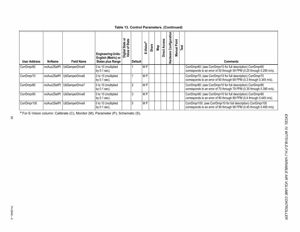
EX
CEL 10 W
7751B,D
,F,H,J VA
RIA
BLE
AIR
VOLU
ME
CO
NTR
OLLE
R
5974-2949—
3
CorrDmpr60 nciAux2SetPt UbDamperDrive5 0 to 10 (multiplied by 0.1 sec).
1 M P CorrDmpr60: (see CorrDmpr10 for full description) CorrDmpr60 corresponds to an error of 50 through 59 FPM (0.25 through 0.295 m/s).
CorrDmpr70 nciAux2SetPt UbDamperDrive6 0 to 10 (multiplied by 0.1 sec).
1 M P CorrDmpr70: (see CorrDmpr10 for full description) CorrDmpr70 corresponds to an error of 60 through 69 FPM (0.3 through 0.345 m/s).
CorrDmpr80 nciAux2SetPt UbDamperDrive7 0 to 10 (multiplied by 0.1 sec).
2 M P CorrDmpr80: (see CorrDmpr10 for full description) CorrDmpr80 corresponds to an error of 70 through 79 FPM (0.35 through 0.395 m/s).
CorrDmpr90 nciAux2SetPt UbDamperDrive8 0 to 10 (multiplied by 0.1 sec).
3 M P CorrDmpr90: (see CorrDmpr10 for full description) CorrDmpr90 corresponds to an error of 80 through 89 FPM (0.4 through 0.445 m/s).
CorrDmpr100 nciAux2SetPt UbDamperDrive9 0 to 10 (multiplied by 0.1 sec).
5 M P CorrDmpr100: (see CorrDmpr10 for full description) CorrDmpr100 corresponds to an error of 90 through 99 FPM (0.45 through 0.495 m/s).
Table 13. Control Parameters. (Continued)
User Address NvName Field Name
Engineering Units: English (Metric) or States plus Range
Digi
tal S
tate
or
Valu
e of S
tate
Default
E-Vi
siona
Shar
e
Map
Dire
ct A
cces
s
Hard
ware
Con
figur
atio
n
Manu
al Po
int
Test
Comments
a For E-Vision column: Calibrate (C), Monitor (M), Parameter (P), Schematic (S).
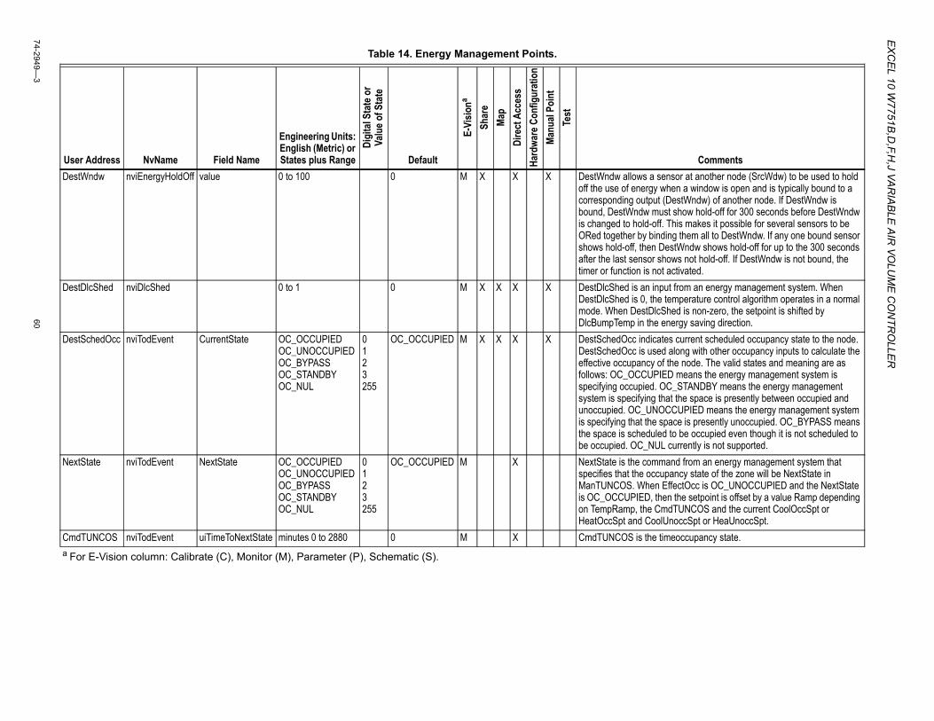
EX
CE
L 10 W7751B
,D,F,H
,J VAR
IAB
LE A
IR VO
LUM
E C
ON
TRO
LLER
74-2949—3
60
Table 14. Energy Management Points.
User Address NvName Field Name
Engineering Units: English (Metric) or States plus Range
Digi
tal S
tate
or
Valu
e of S
tate
Default
E-Vi
siona
Shar
eMa
pDi
rect
Acc
ess
Hard
ware
Con
figur
atio
nMa
nual
Poin
tTe
st
CommentsDestWndw nviEnergyHoldOff value 0 to 100 0 M X X X DestWndw allows a sensor at another node (SrcWdw) to be used to hold
off the use of energy when a window is open and is typically bound to a corresponding output (DestWndw) of another node. If DestWndw is bound, DestWndw must show hold-off for 300 seconds before DestWndw is changed to hold-off. This makes it possible for several sensors to be ORed together by binding them all to DestWndw. If any one bound sensor shows hold-off, then DestWndw shows hold-off for up to the 300 seconds after the last sensor shows not hold-off. If DestWndw is not bound, the timer or function is not activated.
DestDlcShed nviDlcShed 0 to 1 0 M X X X X DestDlcShed is an input from an energy management system. When DestDlcShed is 0, the temperature control algorithm operates in a normal mode. When DestDlcShed is non-zero, the setpoint is shifted by DlcBumpTemp in the energy saving direction.
DestSchedOcc nviTodEvent CurrentState OC_OCCUPIED OC_UNOCCUPIED OC_BYPASS OC_STANDBY OC_NUL
0 1 2 3 255
OC_OCCUPIED M X X X X DestSchedOcc indicates current scheduled occupancy state to the node. DestSchedOcc is used along with other occupancy inputs to calculate the effective occupancy of the node. The valid states and meaning are as follows: OC_OCCUPIED means the energy management system is specifying occupied. OC_STANDBY means the energy management system is specifying that the space is presently between occupied and unoccupied. OC_UNOCCUPIED means the energy management system is specifying that the space is presently unoccupied. OC_BYPASS means the space is scheduled to be occupied even though it is not scheduled to be occupied. OC_NUL currently is not supported.
NextState nviTodEvent NextState OC_OCCUPIED OC_UNOCCUPIED OC_BYPASS OC_STANDBY OC_NUL
0 1 2 3 255
OC_OCCUPIED M X NextState is the command from an energy management system that specifies that the occupancy state of the zone will be NextState in ManTUNCOS. When EffectOcc is OC_UNOCCUPIED and the NextState is OC_OCCUPIED, then the setpoint is offset by a value Ramp depending on TempRamp, the CmdTUNCOS and the current CoolOccSpt or HeatOccSpt and CoolUnoccSpt or HeaUnoccSpt.
CmdTUNCOS nviTodEvent uiTimeToNextState minutes 0 to 2880 0 M X CmdTUNCOS is the timeoccupancy state.a For E-Vision column: Calibrate (C), Monitor (M), Parameter (P), Schematic (S).
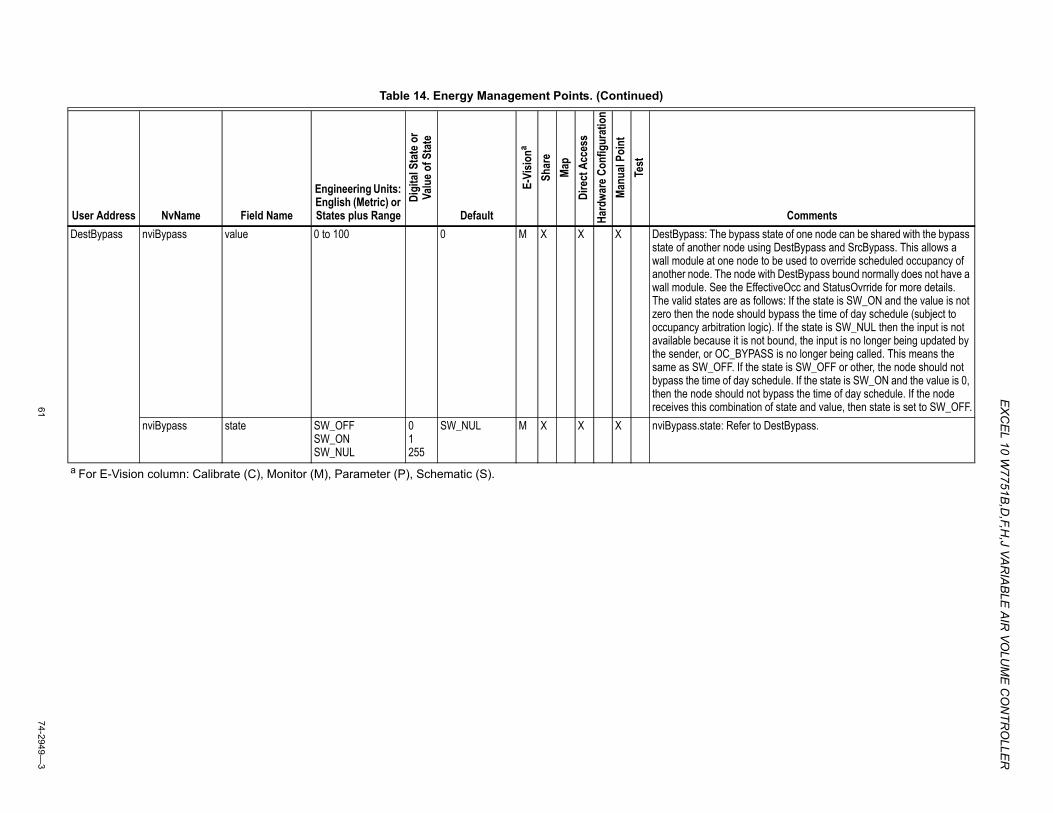
EX
CEL 10 W
7751B,D
,F,H,J VA
RIA
BLE
AIR
VOLU
ME
CO
NTR
OLLE
R
6174-2949—
3
DestBypass nviBypass value 0 to 100 0 M X X X DestBypass: The bypass state of one node can be shared with the bypass state of another node using DestBypass and SrcBypass. This allows a wall module at one node to be used to override scheduled occupancy of another node. The node with DestBypass bound normally does not have a wall module. See the EffectiveOcc and StatusOvrride for more details. The valid states are as follows: If the state is SW_ON and the value is not zero then the node should bypass the time of day schedule (subject to occupancy arbitration logic). If the state is SW_NUL then the input is not available because it is not bound, the input is no longer being updated by the sender, or OC_BYPASS is no longer being called. This means the same as SW_OFF. If the state is SW_OFF or other, the node should not bypass the time of day schedule. If the state is SW_ON and the value is 0, then the node should not bypass the time of day schedule. If the node receives this combination of state and value, then state is set to SW_OFF.
nviBypass state SW_OFF SW_ON SW_NUL
0 1 255
SW_NUL M X X X nviBypass.state: Refer to DestBypass.
Table 14. Energy Management Points. (Continued)
User Address NvName Field Name
Engineering Units: English (Metric) or States plus Range
Digi
tal S
tate
or
Valu
e of S
tate
Default
E-Vi
siona
Shar
eMa
pDi
rect
Acc
ess
Hard
ware
Con
figur
atio
nMa
nual
Poin
tTe
st
Comments
a For E-Vision column: Calibrate (C), Monitor (M), Parameter (P), Schematic (S).
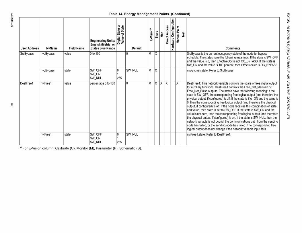
EX
CE
L 10 W7751B
,D,F,H
,J VAR
IAB
LE A
IR VO
LUM
E C
ON
TRO
LLER
74-2949—3
62
SrcBypass nvoBypass value 0 to 100 0 M X SrcBypass is the current occupancy state of the node for bypass schedule. The states have the following meanings: If the state is SW_OFF and the value is 0, then EffectiveOcc is not OC_BYPASS. If the state is SW_ON and the value is 100 percent, then EffectiveOcc is OC_BYPASS.
nvoBypass state SW_OFF SW_ON SW_NUL
0 1 255
SW_NUL M X nvoBypass.state: Refer to SrcBypass.
DestFree1 nviFree1 value percentage 0 to 100 0 M X X X X DestFree1: This network variable controls the spare or free digital output for auxiliary functions. DestFree1 controls the Free_Net_Maintain or Free_Net_Pulse outputs. The states have the following meaning: If the state is SW_OFF, the corresponding free logical output (and therefore the physical output, if configured) is off. If the state is SW_ON and the value is 0, then the corresponding free logical output (and therefore the physical output, if configured) is off. If the node receives this combination of state and value, then state is set to SW_OFF. If the state is SW_ON and the value is not zero, then the corresponding free logical output (and therefore the physical output, if configured) is on. If the state is SW_NUL, then the network variable is not bound, the communications path from the sending node has failed, or the sending node has failed. The corresponding free logical output does not change if the network variable input fails.
nviFree1 state SW_OFF SW_ON SW_NUL
0 1 255
SW_NUL nviFree1.state: Refer to DestFree1.
Table 14. Energy Management Points. (Continued)
User Address NvName Field Name
Engineering Units: English (Metric) or States plus Range
Digi
tal S
tate
or
Valu
e of S
tate
Default
E-Vi
siona
Shar
eMa
pDi
rect
Acc
ess
Hard
ware
Con
figur
atio
nMa
nual
Poin
tTe
st
Comments
a For E-Vision column: Calibrate (C), Monitor (M), Parameter (P), Schematic (S).
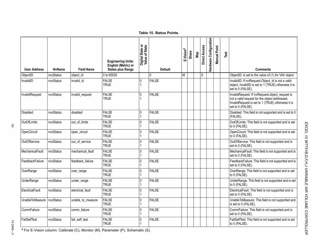
EX
CEL 10 W
7751B,D
,F,H,J VA
RIA
BLE
AIR
VOLU
ME
CO
NTR
OLLE
R
6374-2949—
3
Table 15. Status Points.
User Address NvName Field Name
Engineering Units: English (Metric) or States plus Range
Digi
tal S
tate
or
Valu
e of S
tate
Default
E-Vi
siona
Shar
e
Map
Dire
ct A
cces
s
Hard
ware
Con
figur
atio
n
Manu
al Po
int
Test
CommentsObjectID nvoStatus object_id 0 to 65535 0 M X ObjectID: is set to the value of (1) for VAV objectInvalidID nvoStatus invalid_id FALSE
TRUE0 1
FALSE InvalidID: If nviRequest.Object_id is not a valid object, InvalidID is set to 1 (TRUE) otherwise it is set to 0 (FALSE).
InvalidRequest nvoStatus invalid_request FALSE TRUE
0 1
FALSE InvalidRequest: If nviRequest.object_request is not a valid request for the object addressed, InvalidRequest is set to 1 (TRUE) otherwise it is set to 0 (FALSE).
Disabled nvoStatus disabled FALSE TRUE
0 1
FALSE Disabled: This field is not supported and is set to 0 (FALSE).
OutOfLimits nvoStatus out_of_limits FALSE TRUE
0 1
FALSE OutOfLimits: This field is not supported and is set to 0 (FALSE).
OpenCircuit nvoStatus open_circuit FALSE TRUE
0 1
FALSE OpenCircuit: This field is not supported and is set to 0 (FALSE).
OutOfService nvoStatus out_of_service FALSE TRUE
0 1
FALSE OutOfService: This field is not supported and is set to 0 (FALSE).
MechanicalFault nvoStatus mechanical_fault FALSE TRUE
0 1
FALSE MechanicalFault: This field is not supported and is set to 0 (FALSE).
FeedbackFailure nvoStatus feedback_failure FALSE TRUE
0 1
FALSE FeedbackFailure: This field is not supported and is set to 0 (FALSE).
OverRange nvoStatus over_range FALSE TRUE
0 1
FALSE OverRange: This field is not supported and is set to 0 (FALSE).
UnderRange nvoStatus under_range FALSE TRUE
0 1
FALSE UnderRange: This field is not supported and is set to 0 (FALSE).
ElectricalFault nvoStatus electrical_fault FALSE TRUE
0 1
FALSE ElectricalFault: This field is not supported and is set to 0 (FALSE).
UnableToMeasure nvoStatus unable_to_measure FALSE TRUE
0 1
FALSE UnableToMeasure: This field is not supported and is set to 0 (FALSE).
CommFailure nvoStatus comm_failure FALSE TRUE
0 1
FALSE CommFailure: This field is not supported and is set to 0 (FALSE).
FailSelfTest nvoStatus fail_self_test FALSE TRUE
0 1
FALSE FailSelfTest: This field is not supported and is set to 0 (FALSE).
a For E-Vision column: Calibrate (C), Monitor (M), Parameter (P), Schematic (S).
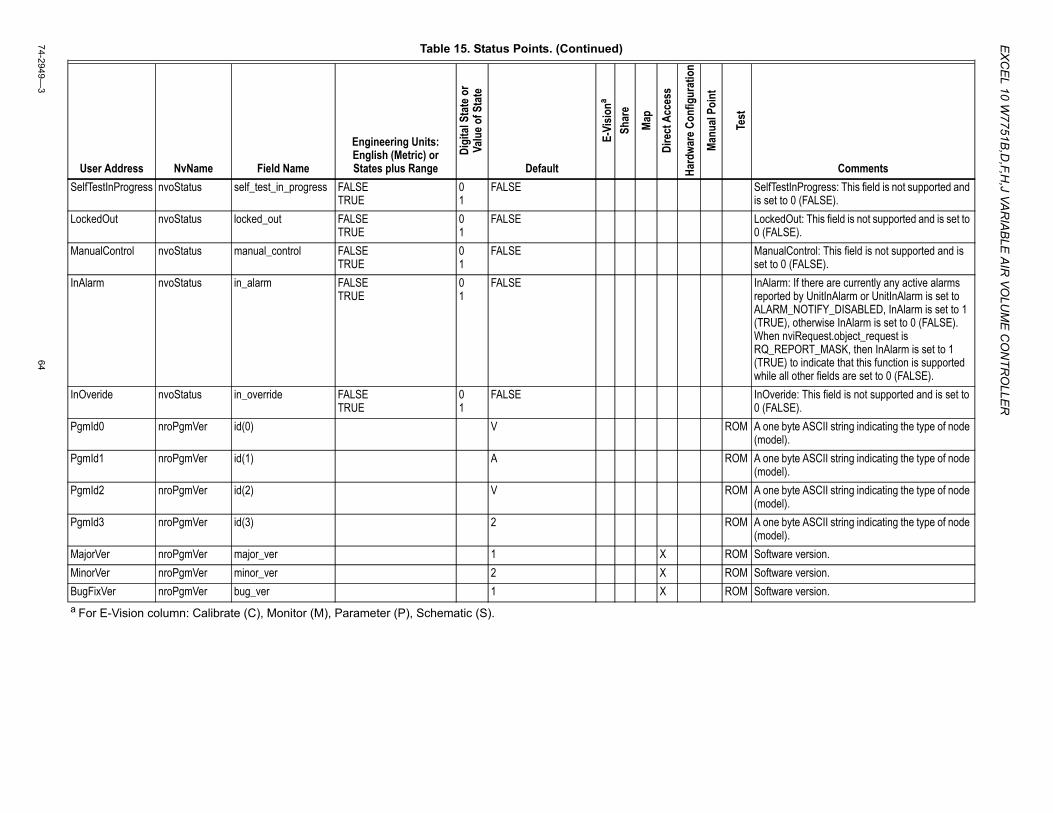
EX
CE
L 10 W7751B
,D,F,H
,J VAR
IAB
LE A
IR VO
LUM
E C
ON
TRO
LLER
74-2949—3
64
SelfTestInProgress nvoStatus self_test_in_progress FALSE TRUE
0 1
FALSE SelfTestInProgress: This field is not supported and is set to 0 (FALSE).
LockedOut nvoStatus locked_out FALSE TRUE
0 1
FALSE LockedOut: This field is not supported and is set to 0 (FALSE).
ManualControl nvoStatus manual_control FALSE TRUE
0 1
FALSE ManualControl: This field is not supported and is set to 0 (FALSE).
InAlarm nvoStatus in_alarm FALSE TRUE
0 1
FALSE InAlarm: If there are currently any active alarms reported by UnitInAlarm or UnitInAlarm is set to ALARM_NOTIFY_DISABLED, InAlarm is set to 1 (TRUE), otherwise InAlarm is set to 0 (FALSE). When nviRequest.object_request is RQ_REPORT_MASK, then InAlarm is set to 1 (TRUE) to indicate that this function is supported while all other fields are set to 0 (FALSE).
InOveride nvoStatus in_override FALSE TRUE
0 1
FALSE InOveride: This field is not supported and is set to 0 (FALSE).
PgmId0 nroPgmVer id(0) V ROM A one byte ASCII string indicating the type of node (model).
PgmId1 nroPgmVer id(1) A ROM A one byte ASCII string indicating the type of node (model).
PgmId2 nroPgmVer id(2) V ROM A one byte ASCII string indicating the type of node (model).
PgmId3 nroPgmVer id(3) 2 ROM A one byte ASCII string indicating the type of node (model).
MajorVer nroPgmVer major_ver 1 X ROM Software version.MinorVer nroPgmVer minor_ver 2 X ROM Software version.BugFixVer nroPgmVer bug_ver 1 X ROM Software version.
Table 15. Status Points. (Continued)
User Address NvName Field Name
Engineering Units: English (Metric) or States plus Range
Digi
tal S
tate
or
Valu
e of S
tate
Default
E-Vi
siona
Shar
e
Map
Dire
ct A
cces
s
Hard
ware
Con
figur
atio
n
Manu
al Po
int
Test
Comments
a For E-Vision column: Calibrate (C), Monitor (M), Parameter (P), Schematic (S).

EX
CEL 10 W
7751B,D
,F,H,J VA
RIA
BLE
AIR
VOLU
ME
CO
NTR
OLLE
R
6574-2949—
3
PgmVerNodeType nroPgmVer node_type 3 ROM The NodeType is a numeric identifier that is stored in EPROM that identifies the Excel 10 node type. Whenever a new software version or upgrade is issued, this is reflected in PgmVerNodeType which typically is read by a network management node to identify the node type. The contents of PgmVerNodeType contain compatible model type information and is fixed at the time when the node software is compiled.
AlarmSubnet nvoAlarm subnet 1 to 255 0 AlarmSubnet is the LonWorksÒsubnet number (in domain entry 1 of the nodes domain table) to which the node is assigned.
AlarmNode nvoAlarm node 0 to 127 0 AlarmNode is the LonWorksÒnode number (in domain entry 1 of the nodes domain table) assigned to the node.
AlarmType nvoAlarm type 0 to 255 NO_ALARM COMM_FAILED SENSOR_FAILED INVALID_CONFIG INVALID_SETPOINT NODE_DISABLED_ALM FROST_PROTECT_ALM SMOKE_ALARM Comm_Failed_Rtn Sensor_Failed_Rtn Invalid_Config_Rtn Invalid_Setpt_Rtn Node_Disabled_Rtn Frost_Protect_Rnt Smoke_Alarm_Rtn ALM_NOTIFY_DISABLED
0 1 2 3 4 5 6 7 129 130 131 132 133 134 135 255
NO_ALARM AlarmType is the alarm type being issued. When an alarm condition is no longer TRUE, AlarmType is set to the sum of the alarm conditions numeric value and the RETURN_TO_NORMAL numeric value. The type also is recorded in AlarmLog(0 to 4). When a new alarm is detected, just the corresponding numeric value for the alarm is reported. Refer to Table 13 (Excel 10 Alarms) in the System Engineering Guide for all the error conditions that can be reported.
AlarmStatus0 nvoAlarmStatus alarm_bit(0) Byte Offset = 0 Bit Offset = 0 (CommFail)
FALSE TRUE
0 1
FALSE X X alarm_bit(0) Byte Offset = 0 Bit Offset = 0 (CommFail) alarm_bit (n) contains a bit for every possible alarm condition. Each alarm type has a corresponding bit in alarm_bit (n) (AlarmType: 1.24, without RETURN_TO_NORMAL).
Table 15. Status Points. (Continued)
User Address NvName Field Name
Engineering Units: English (Metric) or States plus Range
Digi
tal S
tate
or
Valu
e of S
tate
Default
E-Vi
siona
Shar
e
Map
Dire
ct A
cces
s
Hard
ware
Con
figur
atio
n
Manu
al Po
int
Test
Comments
a For E-Vision column: Calibrate (C), Monitor (M), Parameter (P), Schematic (S).
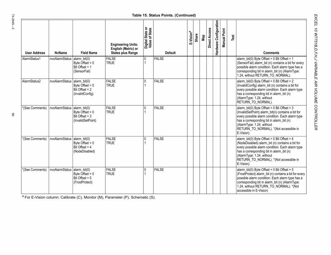
EX
CE
L 10 W7751B
,D,F,H
,J VAR
IAB
LE A
IR VO
LUM
E C
ON
TRO
LLER
74-2949—3
66
AlarmStatus1 nvoAlarmStatus alarm_bit(0) Byte Offset = 0 Bit Offset = 1 (SensorFail)
FALSE TRUE
0 1
FALSE alarm_bit(0) Byte Offset = 0 Bit Offset = 1 (SensorFail) alarm_bit (n) contains a bit for every possible alarm condition. Each alarm type has a corresponding bit in alarm_bit (n) (AlarmType: 1.24, without RETURN_TO_NORMAL).
AlarmStatus2 nvoAlarmStatus alarm_bit(0) Byte Offset = 0 Bit Offset = 2 (InvalidConfig)
FALSE TRUE
0 1
FALSE alarm_bit(0) Byte Offset = 0 Bit Offset = 2 (InvalidConfig) alarm_bit (n) contains a bit for every possible alarm condition. Each alarm type has a corresponding bit in alarm_bit (n) (AlarmType: 1.24, without RETURN_TO_NORMAL).
*(See Comments) nvoAlarmStatus alarm_bit(0) Byte Offset = 0 Bit Offset = 3 (InvalidSetPoint)
FALSE TRUE
0 1
FALSE alarm_bit(0) Byte Offset = 0 Bit Offset = 3 (InvalidSetPoint) alarm_bit(n) contains a bit for every possible alarm condition. Each alarm type has a corresponding bit in alarm_bit (n) (AlarmType: 1.24, without RETURN_TO_NORMAL). *(Not accessible in E-Vision)
*(See Comments) nvoAlarmStatus alarm_bit(0) Byte Offset = 0 Bit Offset = 4 (NodeDisabled)
FALSE TRUE
0 1
FALSE alarm_bit(0) Byte Offset = 0 Bit Offset = 4 (NodeDisabled) alarm_bit (n) contains a bit for every possible alarm condition. Each alarm type has a corresponding bit in alarm_bit (n) (AlarmType: 1.24, without RETURN_TO_NORMAL). *(Not accessible in E-Vision)
*(See Comments) nvoAlarmStatus alarm_bit(0) Byte Offset = 0 Bit Offset = 5 (FrostProtect)
FALSE TRUE
0 1
FALSE alarm_bit(0) Byte Offset = 0 Bit Offset = 5 (FrostProtect) alarm_bit (n) contains a bit for every possible alarm condition. Each alarm type has a corresponding bit in alarm_bit (n) (AlarmType: 1.24, without RETURN_TO_NORMAL). *(Not accessible in E-Vision)
Table 15. Status Points. (Continued)
User Address NvName Field Name
Engineering Units: English (Metric) or States plus Range
Digi
tal S
tate
or
Valu
e of S
tate
Default
E-Vi
siona
Shar
e
Map
Dire
ct A
cces
s
Hard
ware
Con
figur
atio
n
Manu
al Po
int
Test
Comments
a For E-Vision column: Calibrate (C), Monitor (M), Parameter (P), Schematic (S).
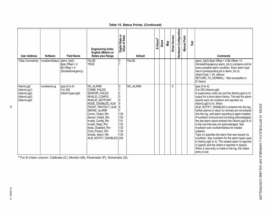
EX
CEL 10 W
7751B,D
,F,H,J VA
RIA
BLE
AIR
VOLU
ME
CO
NTR
OLLE
R
6774-2949—
3
*(See Comments) nvoAlarmStatus alarm_bit(0) Byte Offset = 0 Bit Offset = 6 (SmokeEmergency)
FALSE TRUE
0 1
FALSE alarm_bit(0) Byte Offset = 0 Bit Offset = 6 (SmokeEmergency) alarm_bit (n) contains a bit for every possible alarm condition. Each alarm type has a corresponding bit in alarm_bit (n) (AlarmType: 1.24, without RETURN_TO_NORMAL). *(Not accessible in E-Vision)
AlarmLog0 (AlarmLog1) (AlarmLog2) (AlarmLog3) (AlarmLog4)
nvoAlarmLog type (0 to 4) 0 to 255 (AlarmTypeLog0)
NO_ALARMCOMM_FAILEDSENSOR_FAILEDINVALID_CONFIGINVALID_SETPOINTNODE_DISABLED_ALMFROST_PROTECT_ALMSMOKE_ALARMComm_Failed_RtnSensor_Failed_RtnInvalid_Config_RtnInvalid_Setpt_RntNode_Disabled_RntFrost_Protect_RntSmoke_Alarm_RtnALM_NOTIFY_DISABLED
01234567129130131132133134135255
NO_ALARM X type (0 to 4):0 to 255 (AlarmLog0)A supervisory node can poll the AlarmLog(0 to 4) output for a short alarm history. The last five alarm reports sent via nvoAlarm are reported via AlarmLog(0 to 4). When ALM_NOTIFY_DISABLED is entered into the log, further alarms or return to normals are not entered into the log, until alarm reporting is again enabled. If nvoAlarm is bound and not being acknowledged, the last alarm report entered into AlarmLog(0 to 4) is the one that was not acknowledged. See nvoAlarm and nvoAlarmStatus for related subjects.Type (n) specifies the alarm that was issued via nvoAlarm. See nvoAlarm for the alarm types used in AlarmLog(0 to 4). The newest alarm is reported in type(0) and the oldest is reported in type(4). When a new entry is made to the log, the oldest entry is lost.
Table 15. Status Points. (Continued)
User Address NvName Field Name
Engineering Units: English (Metric) or States plus Range
Digi
tal S
tate
or
Valu
e of S
tate
Default
E-Vi
siona
Shar
e
Map
Dire
ct A
cces
s
Hard
ware
Con
figur
atio
n
Manu
al Po
int
Test
Comments
a For E-Vision column: Calibrate (C), Monitor (M), Parameter (P), Schematic (S).
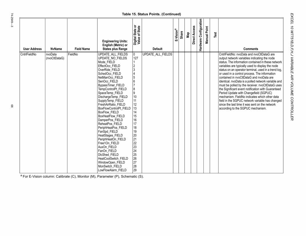
EX
CE
L 10 W7751B
,D,F,H
,J VAR
IAB
LE A
IR VO
LUM
E C
ON
TRO
LLER
74-2949—3
68
CntrlFieldNo nvoData (nvoCtlDataG)
FieldNo UPDATE_ALL_FIELDSUPDATE_NO_FIELDSMode_FIELDEffectOcc_FIELDOverRide_FIELDSchedOcc_FIELDNetManOcc_FIELDSenOcc_FIELDBypassTimer_FIELDTempControlPt_FIELDSpaceTemp_FIELDDischargeTemp_FIELDSupplyTemp_FIELDFreshAirRatio_FIELDBoxFlowControlPt_FIELDBoxFlow_FIELDBoxHeatFlow_FIELDDamperPos_FIELDReheatPos_FIELDPeriphHeatPos_FIELDFanSpd_FIELDHeatStages_FIELDPeriphHeatOn_FIELDFree1On_FIELDAuxOn_FIELDFanOn_FIELDDlcShed_FIELDHeatCoolSwitch_FIELDWindowOpen_FIELDMonSwitch_FIELDLowFlowAlarm_FIELD
01271234567891011121314151617181920212223242526272829
UPDATE_ALL_FIELDS CntrlFieldNo: nvoData and nvoCtlDataG are output network variables indicating the node status. The information contained in these network variables are typically used to display the node status on an operator terminal, used in a trend log, or used in a control process. The information contained in nvoCtlDataG and nvoData are identical. nvoData is a polled network variable and must be polled by the receiver. nvoCtlDataG uses the Significant event notification with Guaranteed Period Update with Changefield (SGPUC) mechanism. FieldNo indicates which other data field in the SGPUC network variable has changed since the last time it was sent on the network according to the SGPUC mechanism.
Table 15. Status Points. (Continued)
User Address NvName Field Name
Engineering Units: English (Metric) or States plus Range
Digi
tal S
tate
or
Valu
e of S
tate
Default
E-Vi
siona
Shar
e
Map
Dire
ct A
cces
s
Hard
ware
Con
figur
atio
n
Manu
al Po
int
Test
Comments
a For E-Vision column: Calibrate (C), Monitor (M), Parameter (P), Schematic (S).
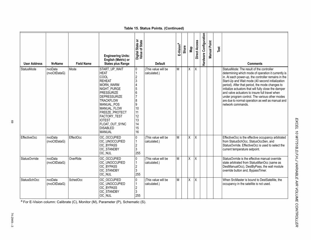
EX
CEL 10 W
7751B,D
,F,H,J VA
RIA
BLE
AIR
VOLU
ME
CO
NTR
OLLE
R
6974-2949—
3
StatusMode nvoData (nvoCtlDataG)
Mode START_UP_WAIT HEAT COOL REHEAT MORN_WARM NIGHT_PURGE PRESSURIZE DEPRESSURIZE TRACKFLOW MANUAL_POS MANUAL_FLOW FREEZE_PROTECT FACTORY_TEST IOTEST FLOAT_OUT_SYNC DISABLED MANUAL
0 1 2 3 4 5 6 7 8 9 10 11 12 13 14 15 16
(This value will be calculated.)
M X X StatusMode: The result of the controller determining which mode of operation it currently is in. At each power-up, the controller remains in the Start-Up and Wait mode (40 second initialization period). After that period, the mode changes to initialize actuators that will fully close the damper and valve actuators to insure full travel when under program control. The various other modes are due to normal operation as well as manual and network commands.
EffectiveOcc nvoData (nvoCtlDataG)
EffectOcc OC_OCCUPIED OC_UNOCCUPIED OC_BYPASS OC_STANDBY OC_NUL
0 1 2 3 255
(This value will be calculated.)
M X X EffectiveOcc is the effective occupancy arbitrated from StatusSchOcc, StatusOccSen, and StatusOvrride. EffectiveOcc is used to select the current temperature setpoint.
StatusOvrride nvoData (nvoCtlDataG)
OverRide OC_OCCUPIED OC_UNOCCUPIED OC_BYPASS OC_STANDBY OC_NUL
0 1 2 3 255
(This value will be calculated.)
M X X StatusOvrride is the effective manual override state arbitrated from StatusManOcc (same as DestManualOcc), DestByPass, the wall module override button and, BypassTimer.
StatusSchOcc nvoData (nvoCtlDataG)
SchedOcc OC_OCCUPIED OC_UNOCCUPIED OC_BYPASS OC_STANDBY OC_NUL
0 1 2 3 255
(This value will be calculated.)
M X X When SrcMaster is bound to DestSatellite, the occupancy in the satellite is not used.
Table 15. Status Points. (Continued)
User Address NvName Field Name
Engineering Units: English (Metric) or States plus Range
Digi
tal S
tate
or
Valu
e of S
tate
Default
E-Vi
siona
Shar
e
Map
Dire
ct A
cces
s
Hard
ware
Con
figur
atio
n
Manu
al Po
int
Test
Comments
a For E-Vision column: Calibrate (C), Monitor (M), Parameter (P), Schematic (S).
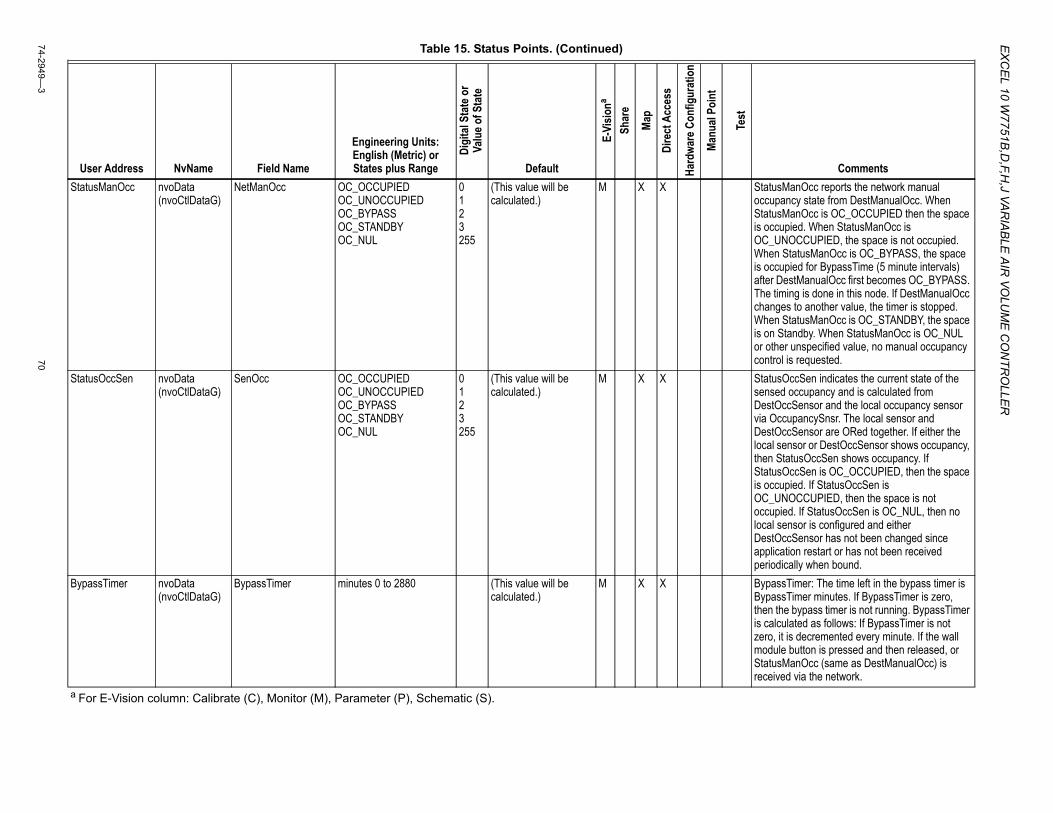
EX
CE
L 10 W7751B
,D,F,H
,J VAR
IAB
LE A
IR VO
LUM
E C
ON
TRO
LLER
74-2949—3
70
StatusManOcc nvoData (nvoCtlDataG)
NetManOcc OC_OCCUPIED OC_UNOCCUPIED OC_BYPASS OC_STANDBY OC_NUL
0 1 2 3 255
(This value will be calculated.)
M X X StatusManOcc reports the network manual occupancy state from DestManualOcc. When StatusManOcc is OC_OCCUPIED then the space is occupied. When StatusManOcc is OC_UNOCCUPIED, the space is not occupied. When StatusManOcc is OC_BYPASS, the space is occupied for BypassTime (5 minute intervals) after DestManualOcc first becomes OC_BYPASS. The timing is done in this node. If DestManualOcc changes to another value, the timer is stopped. When StatusManOcc is OC_STANDBY, the space is on Standby. When StatusManOcc is OC_NUL or other unspecified value, no manual occupancy control is requested.
StatusOccSen nvoData (nvoCtlDataG)
SenOcc OC_OCCUPIED OC_UNOCCUPIED OC_BYPASS OC_STANDBY OC_NUL
0 1 2 3 255
(This value will be calculated.)
M X X StatusOccSen indicates the current state of the sensed occupancy and is calculated from DestOccSensor and the local occupancy sensor via OccupancySnsr. The local sensor and DestOccSensor are ORed together. If either the local sensor or DestOccSensor shows occupancy, then StatusOccSen shows occupancy. If StatusOccSen is OC_OCCUPIED, then the space is occupied. If StatusOccSen is OC_UNOCCUPIED, then the space is not occupied. If StatusOccSen is OC_NUL, then no local sensor is configured and either DestOccSensor has not been changed since application restart or has not been received periodically when bound.
BypassTimer nvoData (nvoCtlDataG)
BypassTimer minutes 0 to 2880 (This value will be calculated.)
M X X BypassTimer: The time left in the bypass timer is BypassTimer minutes. If BypassTimer is zero, then the bypass timer is not running. BypassTimer is calculated as follows: If BypassTimer is not zero, it is decremented every minute. If the wall module button is pressed and then released, or StatusManOcc (same as DestManualOcc) is received via the network.
Table 15. Status Points. (Continued)
User Address NvName Field Name
Engineering Units: English (Metric) or States plus Range
Digi
tal S
tate
or
Valu
e of S
tate
Default
E-Vi
siona
Shar
e
Map
Dire
ct A
cces
s
Hard
ware
Con
figur
atio
n
Manu
al Po
int
Test
Comments
a For E-Vision column: Calibrate (C), Monitor (M), Parameter (P), Schematic (S).
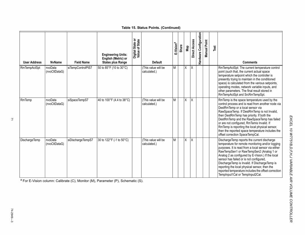
EX
CEL 10 W
7751B,D
,F,H,J VA
RIA
BLE
AIR
VOLU
ME
CO
NTR
OLLE
R
7174-2949—
3
RmTempActSpt nvoData (nvoCtlDataG)
siTempControlPtS7 50 to 85°F (10 to 30°C) (This value will be calculated.)
M X X RmTempActSpt: The current temperature control point (such that, the current actual space temperature setpoint which the controller is presently trying to maintain in the conditioned space) is calculated from the various setpoints, operating modes, network variable inputs, and other parameters. The final result stored in RmTempActSpt and SrcRmTempSpt.
RmTemp nvoData (nvoCtlDataG)
siSpaceTempS7 40 to 100°F (4.4 to 38°C) (This value will be calculated.)
M X X RmTemp is the space temperature used by the control process and is read from another node via DestRmTemp or a local sensor via RawSpaceTemp. If DestRmTemp is not Invalid, then DestRmTemp has priority. If both the DestRmTemp and the RawSpaceTemp has failed or are not configured, RmTemis Invalid. If RmTemp is reporting the local physical sensor, then the reported space temperature includes the offset correction SpaceTempCal.
DischargeTemp nvoData (nvoCtlDataG)
siDischargeTempS7 30 to 122°F (-1 to 50°C) (This value will be calculated.)
M X X DischargeTemp reports the current discharge temperature for remote monitoring and/or logging purposes. It is read from a local sensor via either RawTempSen1 or RawTempSen2 (Analog 1 or Analog 2 as configured by E-Vision.) If the local sensor has failed or is not configured, DischargeTemp is Invalid. If DischargeTemp is reporting the local physical sensor, then the reported temperature includes the offset correction TempInput1Cal or TempInput2Cal.
Table 15. Status Points. (Continued)
User Address NvName Field Name
Engineering Units: English (Metric) or States plus Range
Digi
tal S
tate
or
Valu
e of S
tate
Default
E-Vi
siona
Shar
e
Map
Dire
ct A
cces
s
Hard
ware
Con
figur
atio
n
Manu
al Po
int
Test
Comments
a For E-Vision column: Calibrate (C), Monitor (M), Parameter (P), Schematic (S).
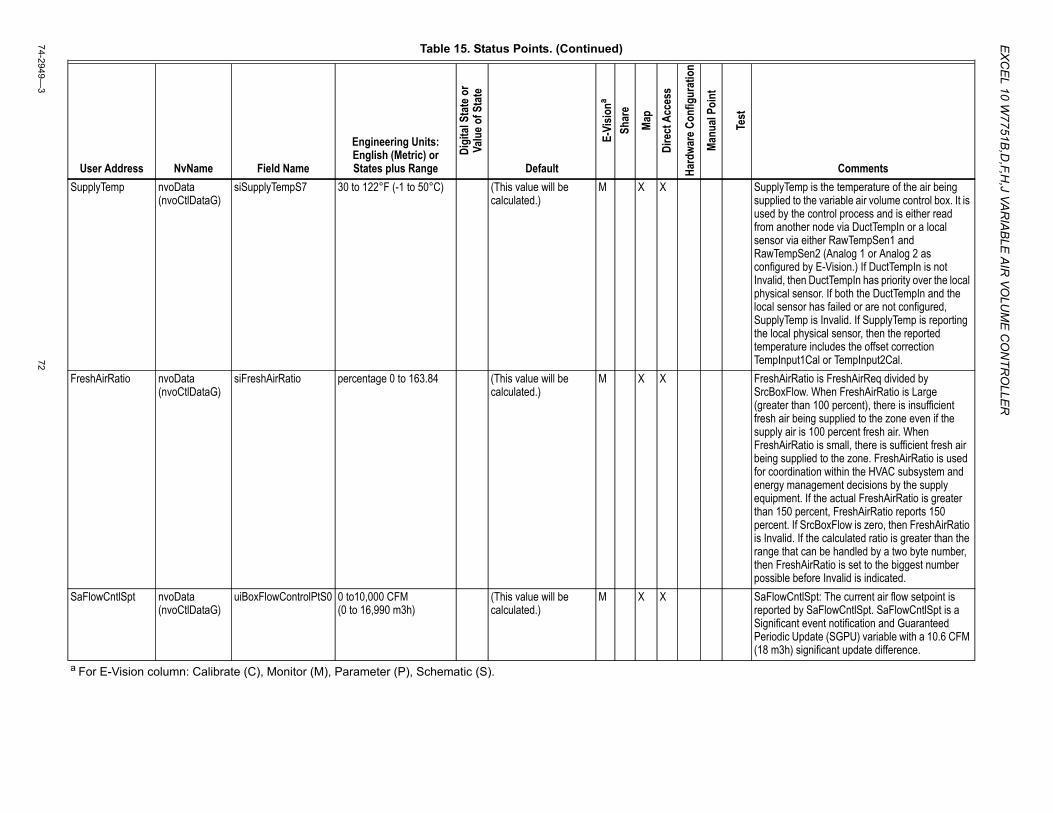
EX
CE
L 10 W7751B
,D,F,H
,J VAR
IAB
LE A
IR VO
LUM
E C
ON
TRO
LLER
74-2949—3
72
SupplyTemp nvoData (nvoCtlDataG)
siSupplyTempS7 30 to 122°F (-1 to 50°C) (This value will be calculated.)
M X X SupplyTemp is the temperature of the air being supplied to the variable air volume control box. It is used by the control process and is either read from another node via DuctTempIn or a local sensor via either RawTempSen1 and RawTempSen2 (Analog 1 or Analog 2 as configured by E-Vision.) If DuctTempIn is not Invalid, then DuctTempIn has priority over the local physical sensor. If both the DuctTempIn and the local sensor has failed or are not configured, SupplyTemp is Invalid. If SupplyTemp is reporting the local physical sensor, then the reported temperature includes the offset correction TempInput1Cal or TempInput2Cal.
FreshAirRatio nvoData (nvoCtlDataG)
siFreshAirRatio percentage 0 to 163.84 (This value will be calculated.)
M X X FreshAirRatio is FreshAirReq divided by SrcBoxFlow. When FreshAirRatio is Large (greater than 100 percent), there is insufficient fresh air being supplied to the zone even if the supply air is 100 percent fresh air. When FreshAirRatio is small, there is sufficient fresh air being supplied to the zone. FreshAirRatio is used for coordination within the HVAC subsystem and energy management decisions by the supply equipment. If the actual FreshAirRatio is greater than 150 percent, FreshAirRatio reports 150 percent. If SrcBoxFlow is zero, then FreshAirRatio is Invalid. If the calculated ratio is greater than the range that can be handled by a two byte number, then FreshAirRatio is set to the biggest number possible before Invalid is indicated.
SaFlowCntlSpt nvoData (nvoCtlDataG)
uiBoxFlowControlPtS0 0 to10,000 CFM (0 to 16,990 m3h)
(This value will be calculated.)
M X X SaFlowCntlSpt: The current air flow setpoint is reported by SaFlowCntlSpt. SaFlowCntlSpt is a Significant event notification and Guaranteed Periodic Update (SGPU) variable with a 10.6 CFM (18 m3h) significant update difference.
Table 15. Status Points. (Continued)
User Address NvName Field Name
Engineering Units: English (Metric) or States plus Range
Digi
tal S
tate
or
Valu
e of S
tate
Default
E-Vi
siona
Shar
e
Map
Dire
ct A
cces
s
Hard
ware
Con
figur
atio
n
Manu
al Po
int
Test
Comments
a For E-Vision column: Calibrate (C), Monitor (M), Parameter (P), Schematic (S).
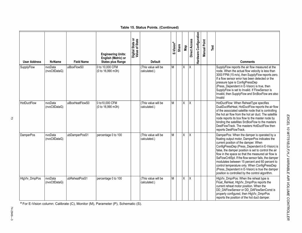
EX
CEL 10 W
7751B,D
,F,H,J VA
RIA
BLE
AIR
VOLU
ME
CO
NTR
OLLE
R
7374-2949—
3
SupplyFlow nvoData (nvoCtlDataG)
uiBoxFlowS0 0 to 10,000 CFM (0 to 16,990 m3h)
(This value will be calculated.)
M X X SupplyFlow reports the air flow measured at the node. When the actual flow velocity is less than 3000 FPM (15 m/s), then SupplyFlow reports zero. If a flow sensor error has been detected or the pressure type is ConfigPressDep (Press_Dependent in E-Vision) is true, then SupplyFlow is set to Invalid. If FlowSensor is Invalid, then SupplyFlow and SrcBoxFlow are also Invalid
HotDuctFlow nvoData (nvoCtlDataG)
uiBoxHeatFlowS0 0 to10,000 CFM (0 to 16,990 m3h)
(This value will be calculated.)
M X X HotDuctFlow: When ReheatType specifies DualDuctReHeat, HotDuctFlow reports the air flow of the associated satellite node that is controlling the hot air flow from the hot air duct. The satellite node reports its box flow to the master node by binding the satellites SrcBoxFlow to the masters DestFlowTrack. The masters HotDuctFlow then reports DestFlowTrack.
DamperPos nvoData (nvoCtlDataG)
ubDamperPosS1 percentage 0 to 100 (This value will be calculated.)
M X X DamperPos: When the damper is operated by a floating output motor, DamperPos indicates the current position of the damper. When ConfigPressDep (Press_Dependent in E-Vision) is false, the damper position is set to control the air flow in the space so that the measured air flow is SaFlowCntlSpt. If the flow sensor fails, the damper modulates between 15 percent and 60 percent to control temperature only. When ConfigPressDep (Press_Dependent in E-Vision) is true the damper position is controlled by the control algorithm.
HtgVlv_DmpPos nvoData (nvoCtlDataG)
ubReheatPosS1 percentage 0 to 100 (This value will be calculated.)
M X X HtgVlv_DmprPos: When the reheat type is Float_ReHeat, HtgVlv_DmprPos reports the current reheat motor position. When the DD_DAFlowSensor or DD_DAFlowSenConst is properly configured, then HtgVlv_DmprPos reports the position of the hot duct damper.
Table 15. Status Points. (Continued)
User Address NvName Field Name
Engineering Units: English (Metric) or States plus Range
Digi
tal S
tate
or
Valu
e of S
tate
Default
E-Vi
siona
Shar
e
Map
Dire
ct A
cces
s
Hard
ware
Con
figur
atio
n
Manu
al Po
int
Test
Comments
a For E-Vision column: Calibrate (C), Monitor (M), Parameter (P), Schematic (S).
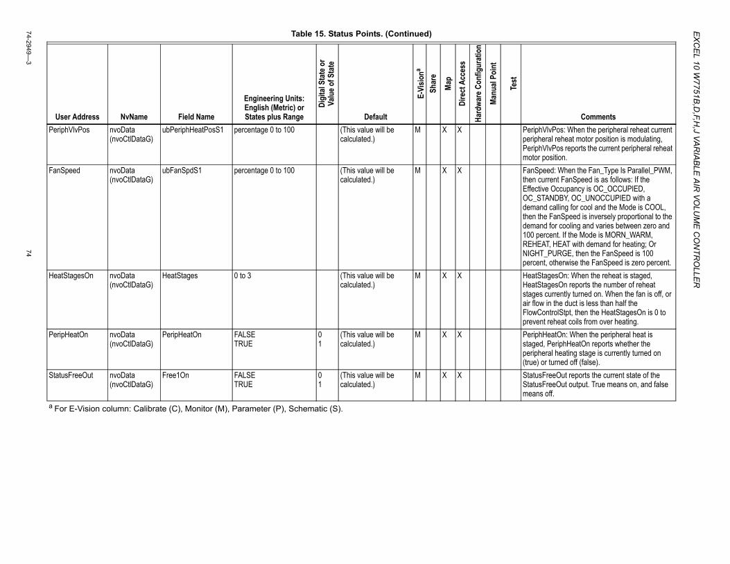
EX
CE
L 10 W7751B
,D,F,H
,J VAR
IAB
LE A
IR VO
LUM
E C
ON
TRO
LLER
74-2949—3
74
PeriphVlvPos nvoData (nvoCtlDataG)
ubPeriphHeatPosS1 percentage 0 to 100 (This value will be calculated.)
M X X PeriphVlvPos: When the peripheral reheat current peripheral reheat motor position is modulating, PeriphVlvPos reports the current peripheral reheat motor position.
FanSpeed nvoData (nvoCtlDataG)
ubFanSpdS1 percentage 0 to 100 (This value will be calculated.)
M X X FanSpeed: When the Fan_Type Is Parallel_PWM, then current FanSpeed is as follows: If the Effective Occupancy is OC_OCCUPIED, OC_STANDBY, OC_UNOCCUPIED with a demand calling for cool and the Mode is COOL, then the FanSpeed is inversely proportional to the demand for cooling and varies between zero and 100 percent. If the Mode is MORN_WARM, REHEAT, HEAT with demand for heating; Or NIGHT_PURGE, then the FanSpeed is 100 percent, otherwise the FanSpeed is zero percent.
HeatStagesOn nvoData (nvoCtlDataG)
HeatStages 0 to 3 (This value will be calculated.)
M X X HeatStagesOn: When the reheat is staged, HeatStagesOn reports the number of reheat stages currently turned on. When the fan is off, or air flow in the duct is less than half the FlowControlStpt, then the HeatStagesOn is 0 to prevent reheat coils from over heating.
PeripHeatOn nvoData (nvoCtlDataG)
PeripHeatOn FALSE TRUE
0 1
(This value will be calculated.)
M X X PeriphHeatOn: When the peripheral heat is staged, PeriphHeatOn reports whether the peripheral heating stage is currently turned on (true) or turned off (false).
StatusFreeOut nvoData (nvoCtlDataG)
Free1On FALSE TRUE
0 1
(This value will be calculated.)
M X X StatusFreeOut reports the current state of the StatusFreeOut output. True means on, and false means off.
Table 15. Status Points. (Continued)
User Address NvName Field Name
Engineering Units: English (Metric) or States plus Range
Digi
tal S
tate
or
Valu
e of S
tate
Default
E-Vi
siona
Shar
e
Map
Dire
ct A
cces
s
Hard
ware
Con
figur
atio
n
Manu
al Po
int
Test
Comments
a For E-Vision column: Calibrate (C), Monitor (M), Parameter (P), Schematic (S).
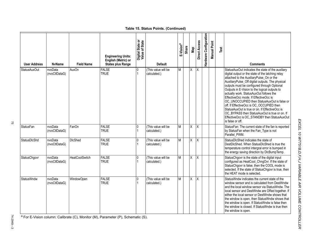
EX
CEL 10 W
7751B,D
,F,H,J VA
RIA
BLE
AIR
VOLU
ME
CO
NTR
OLLE
R
7574-2949—
3
StatusAuxOut nvoData (nvoCtlDataG)
AuxOn FALSE TRUE
0 1
(This value will be calculated.)
M X X StatusAuxOut indicates the state of the auxiliary digital output or the state of the latching relay attached to the AuxiliaryPulse_On or the AuxiliaryPulse_Off digital outputs. The physical outputs must be configured through Optional Outputs in E-Vision to the logical outputs to actually work. StatusAuxOut follows the EffectiveOcc mode. If EffectiveOcc is OC_UNOCCUPIED then StatusAuxOut is false or off. If EffectiveOcc is OC_OCCUPIED then StatusAuxOut is true or on. If EffectiveOcc is OC_BYPASS then StatusAuxOut is true or on. If EffectiveOcc is OC_STANDBY then StatusAuxOut is false or off.
StatusFan nvoData (nvoCtlDataG)
FanOn FALSE TRUE
0 1
(This value will be calculated.)
M X X StatusFan: The current state of the fan is reported by StatusFan when the Fan_Type is not Parallel_PWM.
StatusDlcShd nvoData (nvoCtlDataG)
DlcShed FALSE TRUE
0 1
(This value will be calculated.)
M X X StatusDlcShed indicates the state of DestDlcShed. When StatusDlcShed is true the temperature control intergral error is bumped in the energy saving direction by DlcBumpTemp.
StatusChgovr nvoData (nvoCtlDataG)
HeatCoolSwitch FALSE TRUE
0 1
(This value will be calculated.)
M X X StatusChgovr is the state of the digital input configured as HeatCool_ChngOvr. If the state of StatusChgovr is false, then the COOL mode is selected. If the state of StatusChgovr is true, then the HEAT mode is selected.
StatusWndw nvoData (nvoCtlDataG)
WindowOpen FALSE TRUE
0 1
(This value will be calculated.)
M X X StatusWndw indicates the current state of the window sensor and is calculated from DestWndw and the local window sensor via StatusWndw. The local sensor and DestWndw are ORed together. If either the local sensor or DestWndw shows that the window is open, then StatusWndw shows that the window is open. If StatusWndw is false then the window is closed. If StatusWndw is true then the window is open.
Table 15. Status Points. (Continued)
User Address NvName Field Name
Engineering Units: English (Metric) or States plus Range
Digi
tal S
tate
or
Valu
e of S
tate
Default
E-Vi
siona
Shar
e
Map
Dire
ct A
cces
s
Hard
ware
Con
figur
atio
n
Manu
al Po
int
Test
Comments
a For E-Vision column: Calibrate (C), Monitor (M), Parameter (P), Schematic (S).
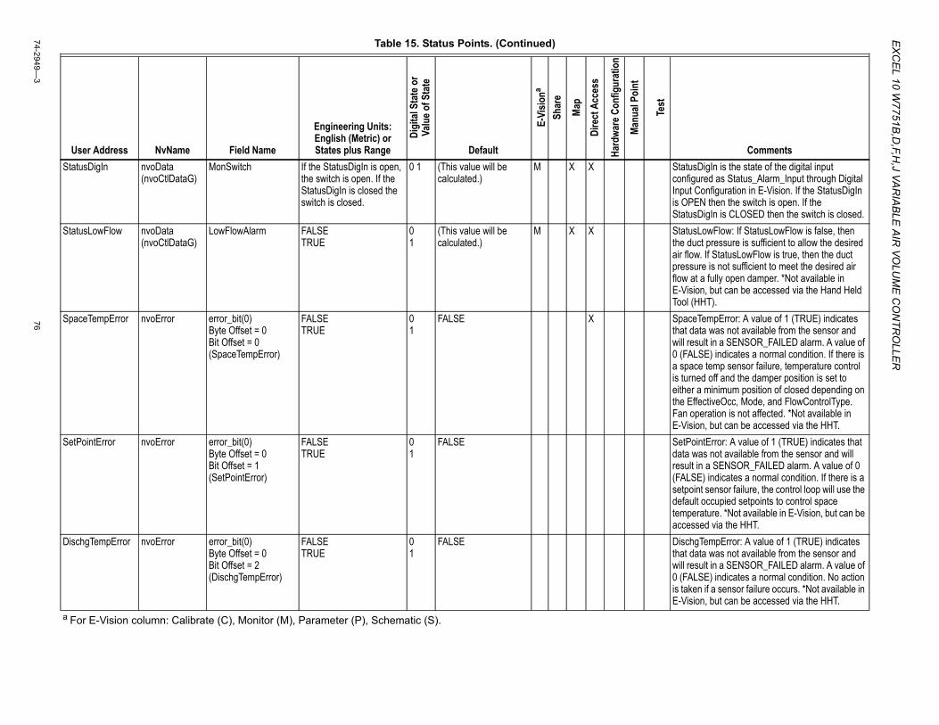
EX
CE
L 10 W7751B
,D,F,H
,J VAR
IAB
LE A
IR VO
LUM
E C
ON
TRO
LLER
74-2949—3
76
StatusDigIn nvoData (nvoCtlDataG)
MonSwitch If the StatusDigIn is open, the switch is open. If the StatusDigIn is closed the switch is closed.
0 1 (This value will be calculated.)
M X X StatusDigIn is the state of the digital input configured as Status_Alarm_Input through Digital Input Configuration in E-Vision. If the StatusDigIn is OPEN then the switch is open. If the StatusDigIn is CLOSED then the switch is closed.
StatusLowFlow nvoData (nvoCtlDataG)
LowFlowAlarm FALSE TRUE
0 1
(This value will be calculated.)
M X X StatusLowFlow: If StatusLowFlow is false, then the duct pressure is sufficient to allow the desired air flow. If StatusLowFlow is true, then the duct pressure is not sufficient to meet the desired air flow at a fully open damper. *Not available in E-Vision, but can be accessed via the Hand Held Tool (HHT).
SpaceTempError nvoError error_bit(0) Byte Offset = 0 Bit Offset = 0 (SpaceTempError)
FALSE TRUE
0 1
FALSE X SpaceTempError: A value of 1 (TRUE) indicates that data was not available from the sensor and will result in a SENSOR_FAILED alarm. A value of 0 (FALSE) indicates a normal condition. If there is a space temp sensor failure, temperature control is turned off and the damper position is set to either a minimum position of closed depending on the EffectiveOcc, Mode, and FlowControlType. Fan operation is not affected. *Not available in E-Vision, but can be accessed via the HHT.
SetPointError nvoError error_bit(0) Byte Offset = 0 Bit Offset = 1 (SetPointError)
FALSE TRUE
0 1
FALSE SetPointError: A value of 1 (TRUE) indicates that data was not available from the sensor and will result in a SENSOR_FAILED alarm. A value of 0 (FALSE) indicates a normal condition. If there is a setpoint sensor failure, the control loop will use the default occupied setpoints to control space temperature. *Not available in E-Vision, but can be accessed via the HHT.
DischgTempError nvoError error_bit(0) Byte Offset = 0 Bit Offset = 2 (DischgTempError)
FALSE TRUE
0 1
FALSE DischgTempError: A value of 1 (TRUE) indicates that data was not available from the sensor and will result in a SENSOR_FAILED alarm. A value of 0 (FALSE) indicates a normal condition. No action is taken if a sensor failure occurs. *Not available in E-Vision, but can be accessed via the HHT.
Table 15. Status Points. (Continued)
User Address NvName Field Name
Engineering Units: English (Metric) or States plus Range
Digi
tal S
tate
or
Valu
e of S
tate
Default
E-Vi
siona
Shar
e
Map
Dire
ct A
cces
s
Hard
ware
Con
figur
atio
n
Manu
al Po
int
Test
Comments
a For E-Vision column: Calibrate (C), Monitor (M), Parameter (P), Schematic (S).
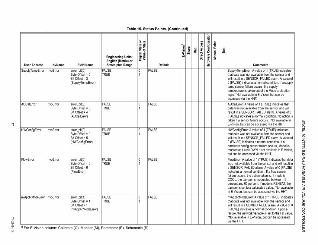
EX
CEL 10 W
7751B,D
,F,H,J VA
RIA
BLE
AIR
VOLU
ME
CO
NTR
OLLE
R
7774-2949—
3
SupplyTempError nvoError error_bit(0) Byte Offset = 0 Bit Offset = 3 (SupplyTempError)
FALSE TRUE
0 1
FALSE SupplyTempError: A value of 1 (TRUE) indicates that data was not available from the sensor and will result in a SENSOR_FAILED alarm. A value of 0 (FALSE) indicates a normal condition. If a supply temp sensor failure occurs, the supply temperature is taken out of the Mode arbitration logic. *Not available in E-Vision, but can be accessed via the HHT.
ADCalError nvoError error_bit(0) Byte Offset = 0 Bit Offset = 4 (ADCalError)
FALSE TRUE
0 1
FALSE ADCalError: A value of 1 (TRUE) indicates that data was not available from the sensor and will result in a SENSOR_FAILED alarm. A value of 0 (FALSE) indicates a normal condition. No action is taken if a sensor failure occurs. *Not available in E-Vision, but can be accessed via the HHT.
HWConfigError nvoError error_bit(0) Byte Offset = 0 Bit Offset = 5 (HWConfigError)
FALSE TRUE
0 1
FALSE HWConfigError: A value of 1 (TRUE) indicates that data was not available from the sensor and will result in a SENSOR_FAILED alarm. A value of 0 (FALSE) indicates a normal condition. If a hardware config sensor failure occurs, Model is marked as UNKNOWN. *Not available in E-Vision, but can be accessed via the HHT.
FlowError nvoError error_bit(0) Byte Offset = 0 Bit Offset = 6 (FlowError)
FALSE TRUE
0 1
FALSE FlowError: A value of 1 (TRUE) indicates that data was not available from the sensor and will result in a SENSOR_FAILED alarm. A value of 0 (FALSE) indicates a normal condition. If a flow sensor failure occurs, the action taken is: If mode is COOL, the damper is modulated between 15 percent and 60 percent. If mode is REHEAT, the damper is set to a calculated value. *Not available in E-Vision, but can be accessed via the HHT.
nvApplicModeError nvoError error_bit(1) Byte Offset = 1 Bit Offset = 1 (nvApplicModeError)
FALSE TRUE
0 1
FALSE nvApplicModeError: A value of 1 (TRUE) indicates that data was not available from the sensor and will result in a COMM_FAILED alarm. A value of 0 (FALSE) indicates a normal condition. Upon a failure, the network variable is set to the FD value. *Not available in E-Vision, but can be accessed via the HHT.
Table 15. Status Points. (Continued)
User Address NvName Field Name
Engineering Units: English (Metric) or States plus Range
Digi
tal S
tate
or
Valu
e of S
tate
Default
E-Vi
siona
Shar
e
Map
Dire
ct A
cces
s
Hard
ware
Con
figur
atio
n
Manu
al Po
int
Test
Comments
a For E-Vision column: Calibrate (C), Monitor (M), Parameter (P), Schematic (S).
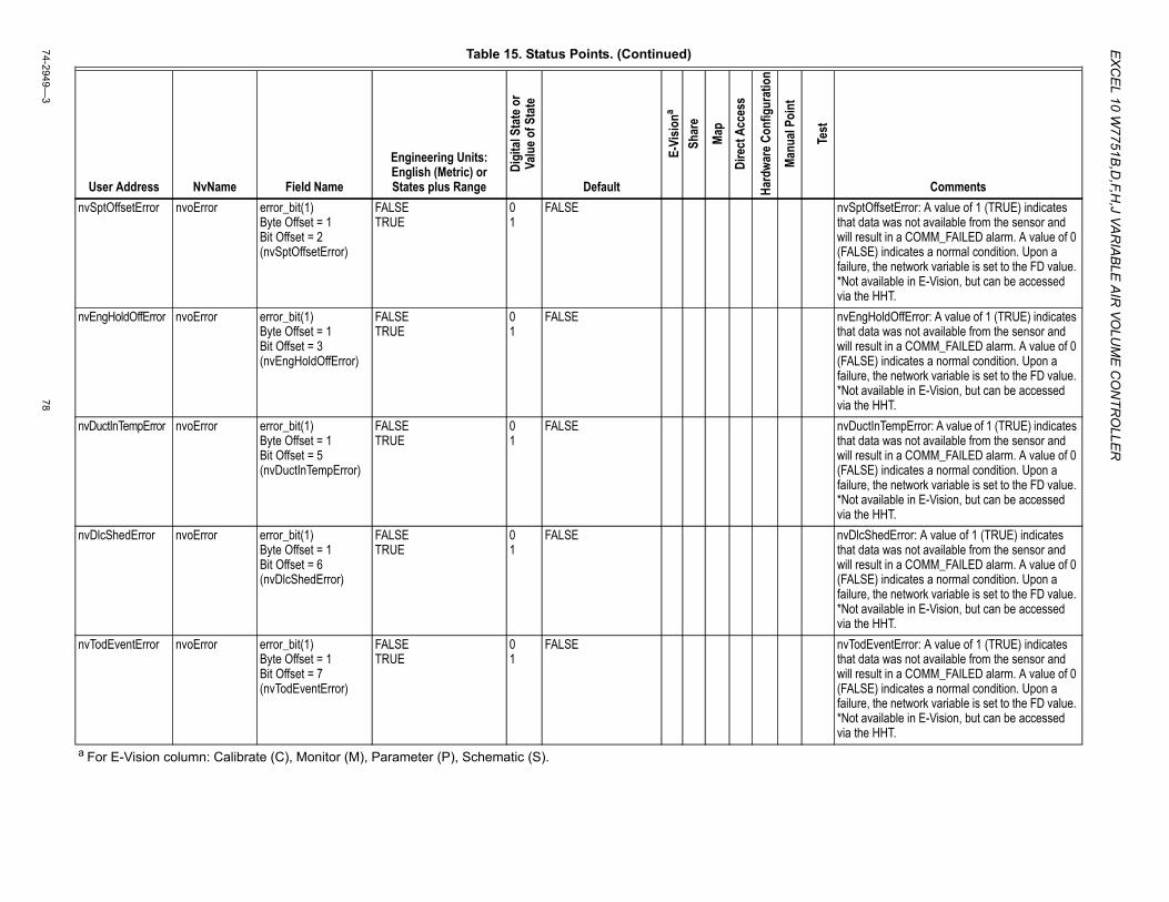
EX
CE
L 10 W7751B
,D,F,H
,J VAR
IAB
LE A
IR VO
LUM
E C
ON
TRO
LLER
74-2949—3
78
nvSptOffsetError nvoError error_bit(1) Byte Offset = 1 Bit Offset = 2 (nvSptOffsetError)
FALSE TRUE
0 1
FALSE nvSptOffsetError: A value of 1 (TRUE) indicates that data was not available from the sensor and will result in a COMM_FAILED alarm. A value of 0 (FALSE) indicates a normal condition. Upon a failure, the network variable is set to the FD value. *Not available in E-Vision, but can be accessed via the HHT.
nvEngHoldOffError nvoError error_bit(1) Byte Offset = 1 Bit Offset = 3 (nvEngHoldOffError)
FALSE TRUE
0 1
FALSE nvEngHoldOffError: A value of 1 (TRUE) indicates that data was not available from the sensor and will result in a COMM_FAILED alarm. A value of 0 (FALSE) indicates a normal condition. Upon a failure, the network variable is set to the FD value. *Not available in E-Vision, but can be accessed via the HHT.
nvDuctInTempError nvoError error_bit(1) Byte Offset = 1 Bit Offset = 5 (nvDuctInTempError)
FALSE TRUE
0 1
FALSE nvDuctInTempError: A value of 1 (TRUE) indicates that data was not available from the sensor and will result in a COMM_FAILED alarm. A value of 0 (FALSE) indicates a normal condition. Upon a failure, the network variable is set to the FD value. *Not available in E-Vision, but can be accessed via the HHT.
nvDlcShedError nvoError error_bit(1) Byte Offset = 1 Bit Offset = 6 (nvDlcShedError)
FALSE TRUE
0 1
FALSE nvDlcShedError: A value of 1 (TRUE) indicates that data was not available from the sensor and will result in a COMM_FAILED alarm. A value of 0 (FALSE) indicates a normal condition. Upon a failure, the network variable is set to the FD value. *Not available in E-Vision, but can be accessed via the HHT.
nvTodEventError nvoError error_bit(1) Byte Offset = 1 Bit Offset = 7 (nvTodEventError)
FALSE TRUE
0 1
FALSE nvTodEventError: A value of 1 (TRUE) indicates that data was not available from the sensor and will result in a COMM_FAILED alarm. A value of 0 (FALSE) indicates a normal condition. Upon a failure, the network variable is set to the FD value. *Not available in E-Vision, but can be accessed via the HHT.
Table 15. Status Points. (Continued)
User Address NvName Field Name
Engineering Units: English (Metric) or States plus Range
Digi
tal S
tate
or
Valu
e of S
tate
Default
E-Vi
siona
Shar
e
Map
Dire
ct A
cces
s
Hard
ware
Con
figur
atio
n
Manu
al Po
int
Test
Comments
a For E-Vision column: Calibrate (C), Monitor (M), Parameter (P), Schematic (S).
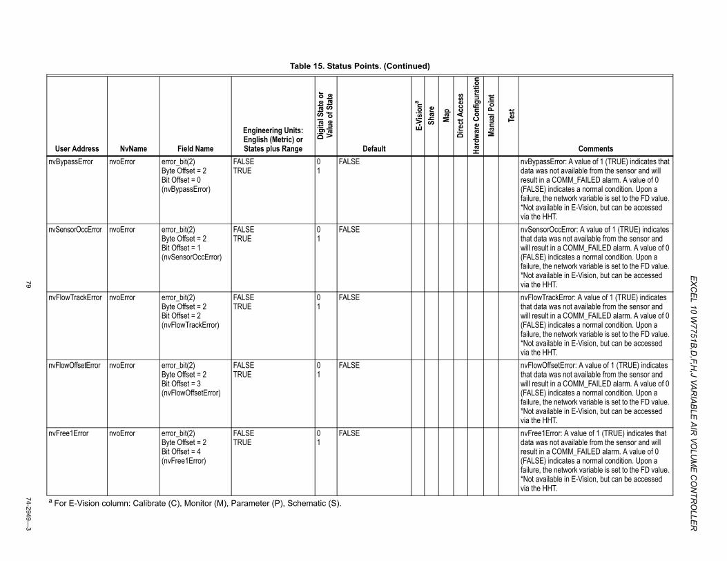
EX
CEL 10 W
7751B,D
,F,H,J VA
RIA
BLE
AIR
VOLU
ME
CO
NTR
OLLE
R
7974-2949—
3
nvBypassError nvoError error_bit(2) Byte Offset = 2 Bit Offset = 0 (nvBypassError)
FALSE TRUE
0 1
FALSE nvBypassError: A value of 1 (TRUE) indicates that data was not available from the sensor and will result in a COMM_FAILED alarm. A value of 0 (FALSE) indicates a normal condition. Upon a failure, the network variable is set to the FD value. *Not available in E-Vision, but can be accessed via the HHT.
nvSensorOccError nvoError error_bit(2) Byte Offset = 2 Bit Offset = 1 (nvSensorOccError)
FALSE TRUE
0 1
FALSE nvSensorOccError: A value of 1 (TRUE) indicates that data was not available from the sensor and will result in a COMM_FAILED alarm. A value of 0 (FALSE) indicates a normal condition. Upon a failure, the network variable is set to the FD value. *Not available in E-Vision, but can be accessed via the HHT.
nvFlowTrackError nvoError error_bit(2) Byte Offset = 2 Bit Offset = 2 (nvFlowTrackError)
FALSE TRUE
0 1
FALSE nvFlowTrackError: A value of 1 (TRUE) indicates that data was not available from the sensor and will result in a COMM_FAILED alarm. A value of 0 (FALSE) indicates a normal condition. Upon a failure, the network variable is set to the FD value. *Not available in E-Vision, but can be accessed via the HHT.
nvFlowOffsetError nvoError error_bit(2) Byte Offset = 2 Bit Offset = 3 (nvFlowOffsetError)
FALSE TRUE
0 1
FALSE nvFlowOffsetError: A value of 1 (TRUE) indicates that data was not available from the sensor and will result in a COMM_FAILED alarm. A value of 0 (FALSE) indicates a normal condition. Upon a failure, the network variable is set to the FD value. *Not available in E-Vision, but can be accessed via the HHT.
nvFree1Error nvoError error_bit(2) Byte Offset = 2 Bit Offset = 4 (nvFree1Error)
FALSE TRUE
0 1
FALSE nvFree1Error: A value of 1 (TRUE) indicates that data was not available from the sensor and will result in a COMM_FAILED alarm. A value of 0 (FALSE) indicates a normal condition. Upon a failure, the network variable is set to the FD value. *Not available in E-Vision, but can be accessed via the HHT.
Table 15. Status Points. (Continued)
User Address NvName Field Name
Engineering Units: English (Metric) or States plus Range
Digi
tal S
tate
or
Valu
e of S
tate
Default
E-Vi
siona
Shar
e
Map
Dire
ct A
cces
s
Hard
ware
Con
figur
atio
n
Manu
al Po
int
Test
Comments
a For E-Vision column: Calibrate (C), Monitor (M), Parameter (P), Schematic (S).
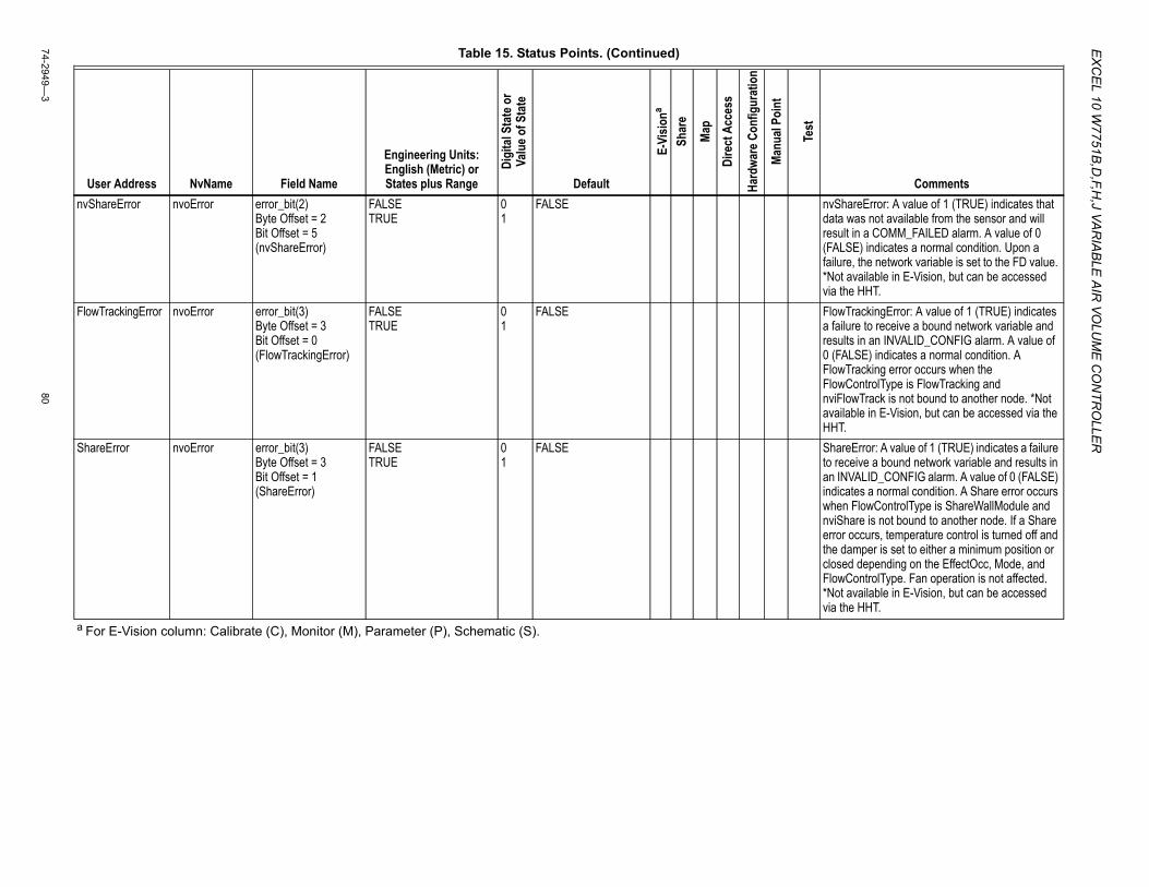
EX
CE
L 10 W7751B
,D,F,H
,J VAR
IAB
LE A
IR VO
LUM
E C
ON
TRO
LLER
74-2949—3
80
nvShareError nvoError error_bit(2) Byte Offset = 2 Bit Offset = 5 (nvShareError)
FALSE TRUE
0 1
FALSE nvShareError: A value of 1 (TRUE) indicates that data was not available from the sensor and will result in a COMM_FAILED alarm. A value of 0 (FALSE) indicates a normal condition. Upon a failure, the network variable is set to the FD value. *Not available in E-Vision, but can be accessed via the HHT.
FlowTrackingError nvoError error_bit(3) Byte Offset = 3 Bit Offset = 0 (FlowTrackingError)
FALSE TRUE
0 1
FALSE FlowTrackingError: A value of 1 (TRUE) indicates a failure to receive a bound network variable and results in an INVALID_CONFIG alarm. A value of 0 (FALSE) indicates a normal condition. A FlowTracking error occurs when the FlowControlType is FlowTracking and nviFlowTrack is not bound to another node. *Not available in E-Vision, but can be accessed via the HHT.
ShareError nvoError error_bit(3) Byte Offset = 3 Bit Offset = 1 (ShareError)
FALSE TRUE
0 1
FALSE ShareError: A value of 1 (TRUE) indicates a failure to receive a bound network variable and results in an INVALID_CONFIG alarm. A value of 0 (FALSE) indicates a normal condition. A Share error occurs when FlowControlType is ShareWallModule and nviShare is not bound to another node. If a Share error occurs, temperature control is turned off and the damper is set to either a minimum position or closed depending on the EffectOcc, Mode, and FlowControlType. Fan operation is not affected. *Not available in E-Vision, but can be accessed via the HHT.
Table 15. Status Points. (Continued)
User Address NvName Field Name
Engineering Units: English (Metric) or States plus Range
Digi
tal S
tate
or
Valu
e of S
tate
Default
E-Vi
siona
Shar
e
Map
Dire
ct A
cces
s
Hard
ware
Con
figur
atio
n
Manu
al Po
int
Test
Comments
a For E-Vision column: Calibrate (C), Monitor (M), Parameter (P), Schematic (S).
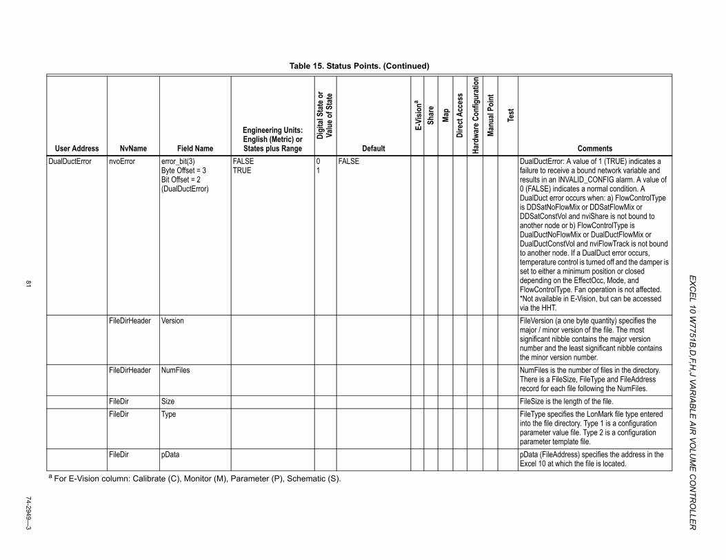
EX
CEL 10 W
7751B,D
,F,H,J VA
RIA
BLE
AIR
VOLU
ME
CO
NTR
OLLE
R
8174-2949—
3
DualDuctError nvoError error_bit(3) Byte Offset = 3 Bit Offset = 2 (DualDuctError)
FALSE TRUE
0 1
FALSE DualDuctError: A value of 1 (TRUE) indicates a failure to receive a bound network variable and results in an INVALID_CONFIG alarm. A value of 0 (FALSE) indicates a normal condition. A DualDuct error occurs when: a) FlowControlType is DDSatNoFlowMix or DDSatFlowMix or DDSatConstVol and nviShare is not bound to another node or b) FlowControlType is DualDuctNoFlowMix or DualDuctFlowMix or DualDuctConstVol and nviFlowTrack is not bound to another node. If a DualDuct error occurs, temperature control is turned off and the damper is set to either a minimum position or closed depending on the EffectOcc, Mode, and FlowControlType. Fan operation is not affected. *Not available in E-Vision, but can be accessed via the HHT.
FileDirHeader Version FileVersion (a one byte quantity) specifies the major / minor version of the file. The most significant nibble contains the major version number and the least significant nibble contains the minor version number.
FileDirHeader NumFiles NumFiles is the number of files in the directory. There is a FileSize, FileType and FileAddress record for each file following the NumFiles.
FileDir Size FileSize is the length of the file.FileDir Type FileType specifies the LonMark file type entered
into the file directory. Type 1 is a configuration parameter value file. Type 2 is a configuration parameter template file.
FileDir pData pData (FileAddress) specifies the address in the Excel 10 at which the file is located.
Table 15. Status Points. (Continued)
User Address NvName Field Name
Engineering Units: English (Metric) or States plus Range
Digi
tal S
tate
or
Valu
e of S
tate
Default
E-Vi
siona
Shar
e
Map
Dire
ct A
cces
s
Hard
ware
Con
figur
atio
n
Manu
al Po
int
Test
Comments
a For E-Vision column: Calibrate (C), Monitor (M), Parameter (P), Schematic (S).
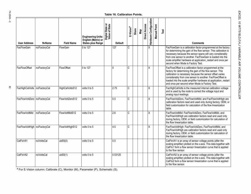
EX
CE
L 10 W7751B
,D,F,H
,J VAR
IAB
LE A
IR VO
LUM
E C
ON
TRO
LLER
74-2949—3
82
Table 16. Calibration Points.
User Address NvName Field Name
Engineering Units: English (Metric) or States plus Range
Digi
tal S
tate
or
Valu
e of S
tate
Default
E-Vi
siona
Shar
e
Map
Dire
ct A
cces
s
Hard
ware
Con
figur
atio
n
Manu
al Po
int
Test
CommentsFacFlowGain nciFactoryCal FlowGain 0 to 127 127 C X FacFlowGain is a calibration factor programmed at the factory
for determining the gain of the flow sensor. This calibration is necessary because the sensor spans will vary considerably from one sensor to another. FacFlowGain is loaded into the scale amplifier hardware at application_restart and once per second when Mode is Factory Test.
FacFlowOffset nciFactoryCal FlowOffset 0 to 127 0 C X FacFlowOffset is a calibration factor programmed at the factory for determining the gain of the flow sensor. This calibration is necessary because the sensor offset varies considerably from one sensor to another. FacFlowOffset is loaded into the scale amplifier hardware at application_restart and once per second when Mode is Factory Test.
FacHighCalVolts nciFactoryCal HighCalVoltsS12 volts 0 to 5 2.75 C X FacHighCalVolts is the measured internal calibration voltage and is used by the node to correct the voltage input and analog input readings.
FacFlowVoltZero nciFactoryCal FlowVoltZeroS12 volts 0 to 5 0.5 C X FacFlowVoltZero, FacFlowVoltMid, and FacFlowVoltHigh are calibration factors read and used only during factory, OEM, or field customization for calculation of the flow linearization table.
FacFlowVoltMid nciFactoryCal FlowVoltMidS12 volts 0 to 5 2.6 C X FacFlowVoltMid: FacFlowVoltZero, FacFlowVoltMid, and FacFlowVoltHigh are calibration factors read and used only during factory, OEM, or field customization for calculation of the flow linearization table.
FacFlowVoltHigh nciFactoryCal FlowVoltHighS12 volts 0 to 5 4.5 C X FacFlowVoltHigh: FacFlowVoltZero, FacFlowVoltMid, and FacFlowVoltHigh are calibration factors read and used only during factory, OEM, or field customization for calculation of the flow linearization table.
CalFloVlt1 nciVoltsCal ubS5(0) volts 0 to 5 0.5 CalFloVlt1 is an array of sensor voltage points (after the scaling amplifier) plotted on the x-axis. This data together with CalFlo1 form a flow sensor linearization curve that is applied to the flow sensor.
CalFloVlt2 nciVoltsCal ubS5(1) volts 0 to 5 0.53125 CalFloVlt2 is an array of sensor voltage points (after the scaling amplifier) plotted on the x-axis. This data together with CalFlo2 form a flow sensor linearization curve that is applied to the flow sensor.
a For E-Vision column: Calibrate (C), Monitor (M), Parameter (P), Schematic (S).
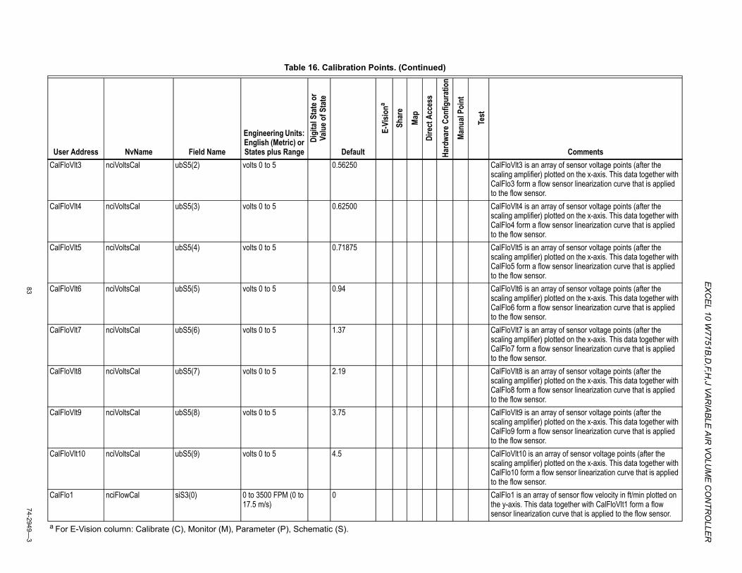
EX
CEL 10 W
7751B,D
,F,H,J VA
RIA
BLE
AIR
VOLU
ME
CO
NTR
OLLE
R
8374-2949—
3
CalFloVlt3 nciVoltsCal ubS5(2) volts 0 to 5 0.56250 CalFloVlt3 is an array of sensor voltage points (after the scaling amplifier) plotted on the x-axis. This data together with CalFlo3 form a flow sensor linearization curve that is applied to the flow sensor.
CalFloVlt4 nciVoltsCal ubS5(3) volts 0 to 5 0.62500 CalFloVlt4 is an array of sensor voltage points (after the scaling amplifier) plotted on the x-axis. This data together with CalFlo4 form a flow sensor linearization curve that is applied to the flow sensor.
CalFloVlt5 nciVoltsCal ubS5(4) volts 0 to 5 0.71875 CalFloVlt5 is an array of sensor voltage points (after the scaling amplifier) plotted on the x-axis. This data together with CalFlo5 form a flow sensor linearization curve that is applied to the flow sensor.
CalFloVlt6 nciVoltsCal ubS5(5) volts 0 to 5 0.94 CalFloVlt6 is an array of sensor voltage points (after the scaling amplifier) plotted on the x-axis. This data together with CalFlo6 form a flow sensor linearization curve that is applied to the flow sensor.
CalFloVlt7 nciVoltsCal ubS5(6) volts 0 to 5 1.37 CalFloVlt7 is an array of sensor voltage points (after the scaling amplifier) plotted on the x-axis. This data together with CalFlo7 form a flow sensor linearization curve that is applied to the flow sensor.
CalFloVlt8 nciVoltsCal ubS5(7) volts 0 to 5 2.19 CalFloVlt8 is an array of sensor voltage points (after the scaling amplifier) plotted on the x-axis. This data together with CalFlo8 form a flow sensor linearization curve that is applied to the flow sensor.
CalFloVlt9 nciVoltsCal ubS5(8) volts 0 to 5 3.75 CalFloVlt9 is an array of sensor voltage points (after the scaling amplifier) plotted on the x-axis. This data together with CalFlo9 form a flow sensor linearization curve that is applied to the flow sensor.
CalFloVlt10 nciVoltsCal ubS5(9) volts 0 to 5 4.5 CalFloVlt10 is an array of sensor voltage points (after the scaling amplifier) plotted on the x-axis. This data together with CalFlo10 form a flow sensor linearization curve that is applied to the flow sensor.
CalFlo1 nciFlowCal siS3(0) 0 to 3500 FPM (0 to 17.5 m/s)
0 CalFlo1 is an array of sensor flow velocity in ft/min plotted on the y-axis. This data together with CalFloVlt1 form a flow sensor linearization curve that is applied to the flow sensor.
Table 16. Calibration Points. (Continued)
User Address NvName Field Name
Engineering Units: English (Metric) or States plus Range
Digi
tal S
tate
or
Valu
e of S
tate
Default
E-Vi
siona
Shar
e
Map
Dire
ct A
cces
s
Hard
ware
Con
figur
atio
n
Manu
al Po
int
Test
Comments
a For E-Vision column: Calibrate (C), Monitor (M), Parameter (P), Schematic (S).
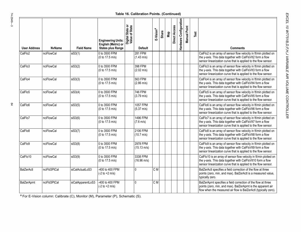
EX
CE
L 10 W7751B
,D,F,H
,J VAR
IAB
LE A
IR VO
LUM
E C
ON
TRO
LLER
74-2949—3
84
CalFlo2 nciFlowCal siS3(1) 0 to 3500 FPM (0 to 17.5 m/s)
281 FPM (1.43 m/s)
CalFlo2 is an array of sensor flow velocity in ft/min plotted on the y-axis. This data together with CalFloVlt2 form a flow sensor linearization curve that is applied to the flow sensor.
CalFlo3 nciFlowCal siS3(2) 0 to 3500 FPM (0 to 17.5 m/s)
398 FPM (2.02 m/s)
CalFlo3 is an array of sensor flow velocity in ft/min plotted on the y-axis. This data together with CalFloVlt3 form a flow sensor linearization curve that is applied to the flow sensor.
CalFlo4 nciFlowCal siS3(3) 0 to 3500 FPM (0 to 17.5 m/s)
563 FPM (2.86 m/s)
CalFlo4 is an array of sensor flow velocity in ft/min plotted on the y-axis. This data together with CalFloVlt4 form a flow sensor linearization curve that is applied to the flow sensor.
CalFlo5 nciFlowCal siS3(4) 0 to 3500 FPM (0 to 17.5 m/s)
746 FPM (3.79 m/s)
CalFlo5 is an array of sensor flow velocity in ft/min plotted on the y-axis. This data together with CalFloVlt5 form a flow sensor linearization curve that is applied to the flow sensor.
CalFlo6 nciFlowCal siS3(5) 0 to 3500 FPM (0 to 17.5 m/s)
1057 FPM (5.37 m/s)
CalFlo6 is an array of sensor flow velocity in ft/min plotted on the y-axis. This data together with CalFloVlt6 form a flow sensor linearization curve that is applied to the flow sensor.
CalFlo7 nciFlowCal siS3(6) 0 to 3500 FPM (0 to 17.5 m/s)
1496 FPM (7.6 m/s)
CalFlo7 is an array of sensor flow velocity in ft/min plotted on the y-axis. This data together with CalFloVlt7 form a flow sensor linearization curve that is applied to the flow sensor.
CalFlo8 nciFlowCal siS3(7) 0 to 3500 FPM (0 to 17.5 m/s)
2106 FPM (10.7 m/s)
CalFlo8 is an array of sensor flow velocity in ft/min plotted on the y-axis. This data together with CalFloVlt8 form a flow sensor linearization curve that is applied to the flow sensor.
CalFlo9 nciFlowCal siS3(8) 0 to 3500 FPM (0 to 17.5 m/s)
2978 FPM (15.13 m/s)
CalFlo9 is an array of sensor flow velocity in ft/min plotted on the y-axis. This data together with CalFloVlt9 form a flow sensor linearization curve that is applied to the flow sensor.
CalFlo10 nciFlowCal siS3(9) 0 to 3500 FPM (0 to 17.5 m/s)
3338 FPM (16.96 m/s)
CalFlo10 is an array of sensor flow velocity in ft/min plotted on the y-axis. This data together with CalFloVlt10 form a flow sensor linearization curve that is applied to the flow sensor.
BalZerActl nciFld3PtCal siCalActualLoS3 -400 to 400 FPM (-2 to +2 m/s)
0 C M BalZerActl specifies a field correction of the flow at three points (zero, min, and max). BalZerActl is a measured value, typically zero.
BalZerAprnt nciFld3PtCal siCalApparentLoS3 -400 to 400 FPM (-2 to +2 m/s)
0 C M BalZerAprnt specifies a field correction of the flow at three points (zero, min, and max). BalZerAprnt is the apparent air flow when the measured air flow is BalZerActl (typically zero).
Table 16. Calibration Points. (Continued)
User Address NvName Field Name
Engineering Units: English (Metric) or States plus Range
Digi
tal S
tate
or
Valu
e of S
tate
Default
E-Vi
siona
Shar
e
Map
Dire
ct A
cces
s
Hard
ware
Con
figur
atio
n
Manu
al Po
int
Test
Comments
a For E-Vision column: Calibrate (C), Monitor (M), Parameter (P), Schematic (S).
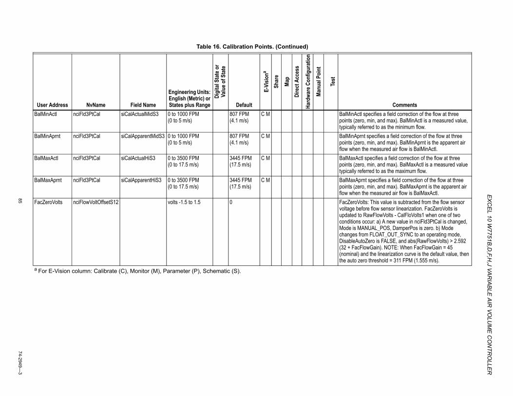
EX
CEL 10 W
7751B,D
,F,H,J VA
RIA
BLE
AIR
VOLU
ME
CO
NTR
OLLE
R
8574-2949—
3
BalMinActl nciFld3PtCal siCalActualMidS3 0 to 1000 FPM (0 to 5 m/s)
807 FPM (4.1 m/s)
C M BalMinActl specifies a field correction of the flow at three points (zero, min, and max). BalMinActl is a measured value, typically referred to as the minimum flow.
BalMinAprnt nciFld3PtCal siCalApparentMidS3 0 to 1000 FPM (0 to 5 m/s)
807 FPM (4.1 m/s)
C M BalMinAprnt specifies a field correction of the flow at three points (zero, min, and max). BalMinAprnt is the apparent air flow when the measured air flow is BalMinActl.
BalMaxActl nciFld3PtCal siCalActualHiS3 0 to 3500 FPM (0 to 17.5 m/s)
3445 FPM (17.5 m/s)
C M BalMaxActl specifies a field correction of the flow at three points (zero, min, and max). BalMaxActl is a measured value typically referred to as the maximum flow.
BalMaxAprnt nciFld3PtCal siCalApparentHiS3 0 to 3500 FPM (0 to 17.5 m/s)
3445 FPM (17.5 m/s)
C M BalMaxAprnt specifies a field correction of the flow at three points (zero, min, and max). BalMaxAprnt is the apparent air flow when the measured air flow is BalMaxActl.
FacZeroVolts nciFlowVoltOffsetS12 volts -1.5 to 1.5 0 FacZeroVolts: This value is subtracted from the flow sensor voltage before flow sensor linearization. FacZeroVolts is updated to RawFlowVolts - CalFloVolts1 when one of two conditions occur: a) A new value in nciFld3PtCal is changed, Mode is MANUAL_POS, DamperPos is zero. b) Mode changes from FLOAT_OUT_SYNC to an operating mode, DisableAutoZero is FALSE, and abs(RawFlowVolts) > 2.592 (32 + FacFlowGain). NOTE: When FacFlowGain = 45 (nominal) and the linearization curve is the default value, then the auto zero threshold = 311 FPM (1.555 m/s).
Table 16. Calibration Points. (Continued)
User Address NvName Field Name
Engineering Units: English (Metric) or States plus Range
Digi
tal S
tate
or
Valu
e of S
tate
Default
E-Vi
siona
Shar
e
Map
Dire
ct A
cces
s
Hard
ware
Con
figur
atio
n
Manu
al Po
int
Test
Comments
a For E-Vision column: Calibrate (C), Monitor (M), Parameter (P), Schematic (S).
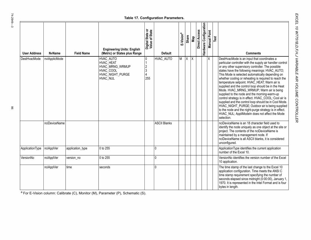
EX
CE
L 10 W7751B
,D,F,H
,J VAR
IAB
LE A
IR VO
LUM
E C
ON
TRO
LLER
74-2949—3
86
Table 17. Configuration Parameters.
User Address NvName Field NameEngineering Units: English
(Metric) or States plus Range
Digi
tal S
tate
or
Valu
e of S
tate
Default
E-Vi
siona
Shar
eMa
pDi
rect
Acc
ess
Hard
ware
Con
figur
atio
nMa
nual
Poin
tTe
st
CommentsDestHvacMode nviApplicMode HVAC_AUTO
HVAC_HEAT HVAC_MRNG_WRMUP HVAC_COOL HVAC_NIGHT_PURGE HVAC_NUL
0 1 2 3 4 255
HVAC_AUTO M X X X DestHvacMode is an input that coordinates a particular controller with the supply air handler control or any other supervisory controller. The possible states have the following meanings: HVAC_AUTO; This Mode is selected automatically depending on whether cooling or reheating is required to reach the temperature setpoint. HVAC_HEAT; Warm air is supplied and the control loop should be in the Heat Mode. HVAC_MRNG_WRMUP; Warm air is being supplied to the node and the morning-warm-up control strategy is in effect. HVAC_COOL; Cool air is supplied and the control loop should be in Cool Mode. HVAC_NIGHT_PURGE; Outdoor air is being supplied to the node and the night-purge strategy is in effect. HVAC_NUL; AppliModeIn does not affect the Mode selection.
nciDeviceName ASCII Blanks nciDeviceName is an 18 character field used to identify the node uniquely as one object at the site or project. The contents of the nciDeviceName is maintained by a management node. If nciDeviceName is all ASCII blanks, it is considered unconfigured.
ApplicationType nciApplVer application_type 0 to 255 0 ApplicationType identifies the current application number of the Excel 10.
VersionNo nciApplVer version_no 0 to 255 0 VersionNo identifies the version number of the Excel 10 application.
nciApplVer time seconds 0 The time stamp of the last change to the Excel 10 application configuration. Time meets the ANSI C time stamp requirement specifying the number of seconds elapsed since midnight (0:00:00), January 1, 1970. It is represented in the Intel Format and is four bytes in length.
a For E-Vision column: Calibrate (C), Monitor (M), Parameter (P), Schematic (S).
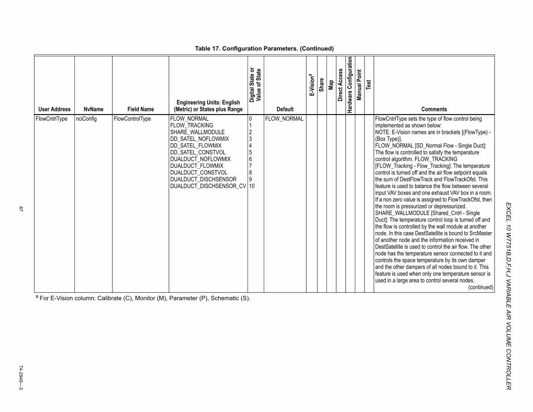
EX
CEL 10 W
7751B,D
,F,H,J VA
RIA
BLE
AIR
VOLU
ME
CO
NTR
OLLE
R
8774-2949—
3
FlowCntrlType nciConfig FlowControlType FLOW_NORMALFLOW_TRACKINGSHARE_WALLMODULEDD_SATEL_NOFLOWMIXDD_SATEL_FLOWMIXDD_SATEL_CONSTVOLDUALDUCT_NOFLOWMIXDUALDUCT_FLOWMIXDUALDUCT_CONSTVOLDUALDUCT_DISCHSENSORDUALDUCT_DISCHSENSOR_CV
012345678910
FLOW_NORMAL FlowCntrlType sets the type of flow control being implemented as shown below:NOTE: E-Vision names are in brackets [(FlowType) - (Box Type)].FLOW_NORMAL [SD_Normal Flow - Single Duct]: The flow is controlled to satisfy the temperature control algorithm. FLOW_TRACKING [FLOW_Tracking - Flow_Tracking]: The temperature control is turned off and the air flow setpoint equals the sum of DestFlowTrack and FlowTrackOfst. This feature is used to balance the flow between several input VAV boxes and one exhaust VAV box in a room. If a non zero value is assigned to FlowTrackOfst, then the room is pressurized or depressurized. SHARE_WALLMODULE [Shared_Cntrl - Single Duct]: The temperature control loop is turned off and the flow is controlled by the wall module at another node. In this case DestSatellite is bound to SrcMaster of another node and the information received in DestSatellite is used to control the air flow. The other node has the temperature sensor connected to it and controls the space temperature by its own damper and the other dampers of all nodes bound to it. This feature is used when only one temperature sensor is used in a large area to control several nodes.
(continued)
Table 17. Configuration Parameters. (Continued)
User Address NvName Field NameEngineering Units: English
(Metric) or States plus Range
Digi
tal S
tate
or
Valu
e of S
tate
Default
E-Vi
siona
Shar
eMa
pDi
rect
Acc
ess
Hard
ware
Con
figur
atio
nMa
nual
Poin
tTe
st
Comments
a For E-Vision column: Calibrate (C), Monitor (M), Parameter (P), Schematic (S).
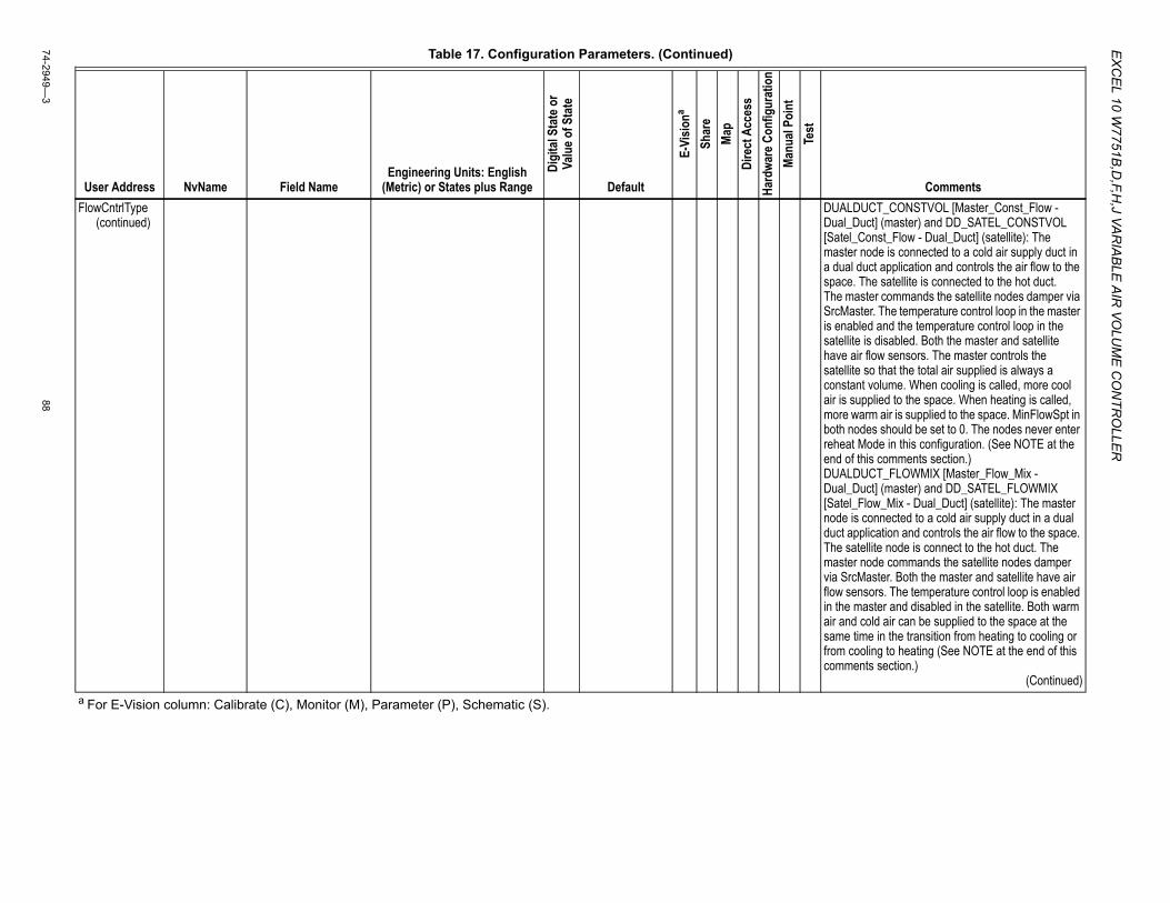
EX
CE
L 10 W7751B
,D,F,H
,J VAR
IAB
LE A
IR VO
LUM
E C
ON
TRO
LLER
74-2949—3
88
FlowCntrlType(continued)
DUALDUCT_CONSTVOL [Master_Const_Flow - Dual_Duct] (master) and DD_SATEL_CONSTVOL [Satel_Const_Flow - Dual_Duct] (satellite): The master node is connected to a cold air supply duct in a dual duct application and controls the air flow to the space. The satellite is connected to the hot duct.The master commands the satellite nodes damper via SrcMaster. The temperature control loop in the master is enabled and the temperature control loop in the satellite is disabled. Both the master and satellite have air flow sensors. The master controls the satellite so that the total air supplied is always a constant volume. When cooling is called, more cool air is supplied to the space. When heating is called, more warm air is supplied to the space. MinFlowSpt in both nodes should be set to 0. The nodes never enter reheat Mode in this configuration. (See NOTE at the end of this comments section.)DUALDUCT_FLOWMIX [Master_Flow_Mix - Dual_Duct] (master) and DD_SATEL_FLOWMIX [Satel_Flow_Mix - Dual_Duct] (satellite): The master node is connected to a cold air supply duct in a dual duct application and controls the air flow to the space. The satellite node is connect to the hot duct. The master node commands the satellite nodes damper via SrcMaster. Both the master and satellite have air flow sensors. The temperature control loop is enabled in the master and disabled in the satellite. Both warm air and cold air can be supplied to the space at the same time in the transition from heating to cooling or from cooling to heating (See NOTE at the end of this comments section.)
(Continued)
Table 17. Configuration Parameters. (Continued)
User Address NvName Field NameEngineering Units: English
(Metric) or States plus Range
Digi
tal S
tate
or
Valu
e of S
tate
Default
E-Vi
siona
Shar
eMa
pDi
rect
Acc
ess
Hard
ware
Con
figur
atio
nMa
nual
Poin
tTe
st
Comments
a For E-Vision column: Calibrate (C), Monitor (M), Parameter (P), Schematic (S).
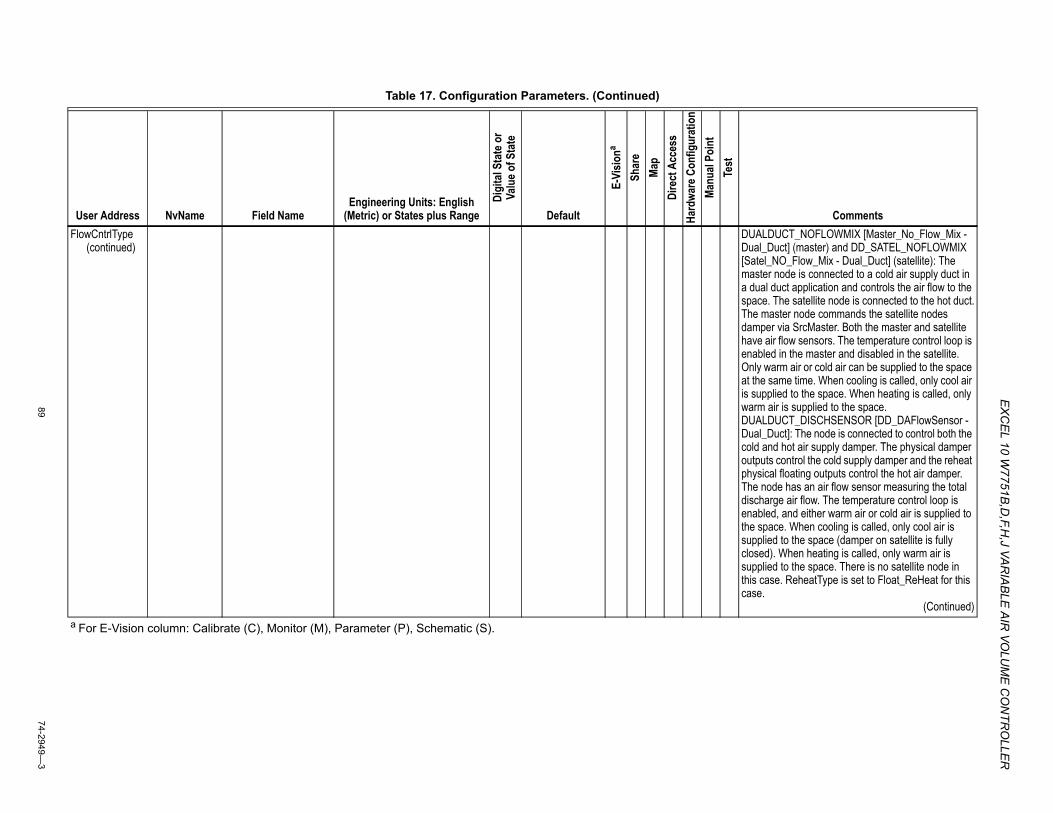
EX
CEL 10 W
7751B,D
,F,H,J VA
RIA
BLE
AIR
VOLU
ME
CO
NTR
OLLE
R
8974-2949—
3
FlowCntrlType(continued)
DUALDUCT_NOFLOWMIX [Master_No_Flow_Mix - Dual_Duct] (master) and DD_SATEL_NOFLOWMIX [Satel_NO_Flow_Mix - Dual_Duct] (satellite): The master node is connected to a cold air supply duct in a dual duct application and controls the air flow to the space. The satellite node is connected to the hot duct.The master node commands the satellite nodes damper via SrcMaster. Both the master and satellite have air flow sensors. The temperature control loop is enabled in the master and disabled in the satellite. Only warm air or cold air can be supplied to the space at the same time. When cooling is called, only cool air is supplied to the space. When heating is called, only warm air is supplied to the space.DUALDUCT_DISCHSENSOR [DD_DAFlowSensor - Dual_Duct]: The node is connected to control both the cold and hot air supply damper. The physical damper outputs control the cold supply damper and the reheat physical floating outputs control the hot air damper. The node has an air flow sensor measuring the total discharge air flow. The temperature control loop is enabled, and either warm air or cold air is supplied to the space. When cooling is called, only cool air is supplied to the space (damper on satellite is fully closed). When heating is called, only warm air is supplied to the space. There is no satellite node in this case. ReheatType is set to Float_ReHeat for this case.
(Continued)
Table 17. Configuration Parameters. (Continued)
User Address NvName Field NameEngineering Units: English
(Metric) or States plus Range
Digi
tal S
tate
or
Valu
e of S
tate
Default
E-Vi
siona
Shar
eMa
pDi
rect
Acc
ess
Hard
ware
Con
figur
atio
nMa
nual
Poin
tTe
st
Comments
a For E-Vision column: Calibrate (C), Monitor (M), Parameter (P), Schematic (S).
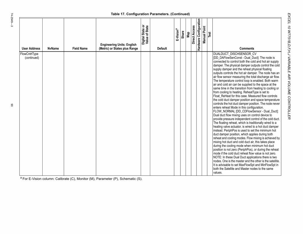
EX
CE
L 10 W7751B
,D,F,H
,J VAR
IAB
LE A
IR VO
LUM
E C
ON
TRO
LLER
74-2949—3
90
FlowCntrlType(continued)
DUALDUCT_DISCHSENSOR_CV [DD_DAFlowSenConst - Dual_Duct]: The node is connected to control both the cold and hot air supply damper. The physical damper outputs control the cold supply damper and the reheat physical floating outputs controls the hot air damper. The node has an air flow sensor measuring the total discharge air flow. The temperature control loop is enabled. Both warm air and cold air can be supplied to the space at the same time in the transition from heating to cooling or from cooling to heating. ReheatType is set to Float_ReHeat for this case. Measured flow controls the cold duct damper position and space temperature controls the hot duct damper position. The node never enters reheat Mode in this configuration.FLOW_NORMAL [DD_CDFlowSensor - Dual_Duct]: Dual duct flow mixing uses on control device to provide pressure independent control of the cold duct. The floating reheat, which is traditionally wired to a heating valve actuator, is wired to a hot duct damper instead. PeriphPos is used to set the minimum hot duct damper position, which applies during both reheat and cooling modes. Flow mixing is achieved by mixing hot duct and cold duct air, this takes place during the cooling mode when minimum hot duct position is not zero (PeriphPos), or during the reheat mode if the cold duct reheat flow value is not zero.NOTE: In these Dual Duct applications there is two nodes. One is the master and the other is the satellite. It is advisable to set MaxFlowSpt and MinFlowSpt in both the Satellite and Master nodes to the same values.
Table 17. Configuration Parameters. (Continued)
User Address NvName Field NameEngineering Units: English
(Metric) or States plus Range
Digi
tal S
tate
or
Valu
e of S
tate
Default
E-Vi
siona
Shar
eMa
pDi
rect
Acc
ess
Hard
ware
Con
figur
atio
nMa
nual
Poin
tTe
st
Comments
a For E-Vision column: Calibrate (C), Monitor (M), Parameter (P), Schematic (S).
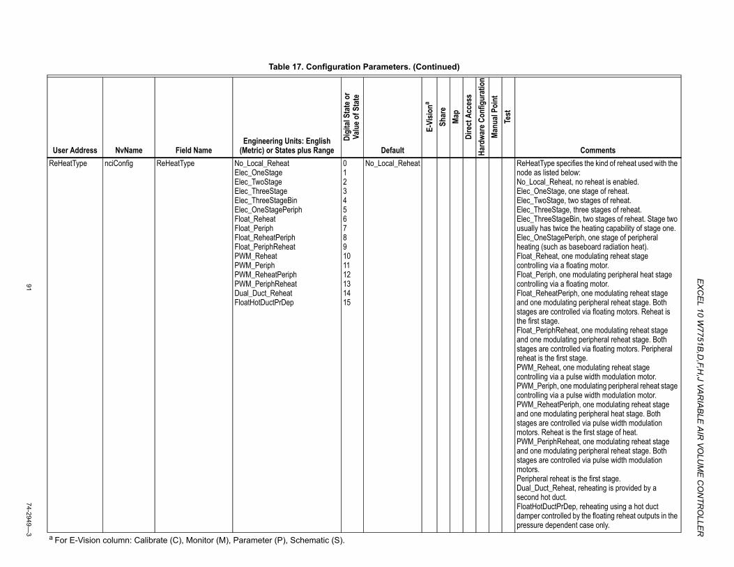
EX
CEL 10 W
7751B,D
,F,H,J VA
RIA
BLE
AIR
VOLU
ME
CO
NTR
OLLE
R
9174-2949—
3
ReHeatType nciConfig ReHeatType No_Local_ReheatElec_OneStageElec_TwoStageElec_ThreeStageElec_ThreeStageBinElec_OneStagePeriphFloat_ReheatFloat_PeriphFloat_ReheatPeriphFloat_PeriphReheatPWM_ReheatPWM_PeriphPWM_ReheatPeriphPWM_PeriphReheatDual_Duct_ReheatFloatHotDuctPrDep
0123456789101112131415
No_Local_Reheat ReHeatType specifies the kind of reheat used with the node as listed below:No_Local_Reheat, no reheat is enabled.Elec_OneStage, one stage of reheat.Elec_TwoStage, two stages of reheat.Elec_ThreeStage, three stages of reheat.Elec_ThreeStageBin, two stages of reheat. Stage two usually has twice the heating capability of stage one.Elec_OneStagePeriph, one stage of peripheral heating (such as baseboard radiation heat).Float_Reheat, one modulating reheat stage controlling via a floating motor.Float_Periph, one modulating peripheral heat stage controlling via a floating motor.Float_ReheatPeriph, one modulating reheat stage and one modulating peripheral reheat stage. Both stages are controlled via floating motors. Reheat is the first stage.Float_PeriphReheat, one modulating reheat stage and one modulating peripheral reheat stage. Both stages are controlled via floating motors. Peripheral reheat is the first stage.PWM_Reheat, one modulating reheat stage controlling via a pulse width modulation motor.PWM_Periph, one modulating peripheral reheat stage controlling via a pulse width modulation motor.PWM_ReheatPeriph, one modulating reheat stage and one modulating peripheral heat stage. Both stages are controlled via pulse width modulation motors. Reheat is the first stage of heat.PWM_PeriphReheat, one modulating reheat stage and one modulating peripheral reheat stage. Both stages are controlled via pulse width modulation motors.Peripheral reheat is the first stage.Dual_Duct_Reheat, reheating is provided by a second hot duct.FloatHotDuctPrDep, reheating using a hot duct damper controlled by the floating reheat outputs in the pressure dependent case only.
Table 17. Configuration Parameters. (Continued)
User Address NvName Field NameEngineering Units: English
(Metric) or States plus Range
Digi
tal S
tate
or
Valu
e of S
tate
Default
E-Vi
siona
Shar
eMa
pDi
rect
Acc
ess
Hard
ware
Con
figur
atio
nMa
nual
Poin
tTe
st
Comments
a For E-Vision column: Calibrate (C), Monitor (M), Parameter (P), Schematic (S).
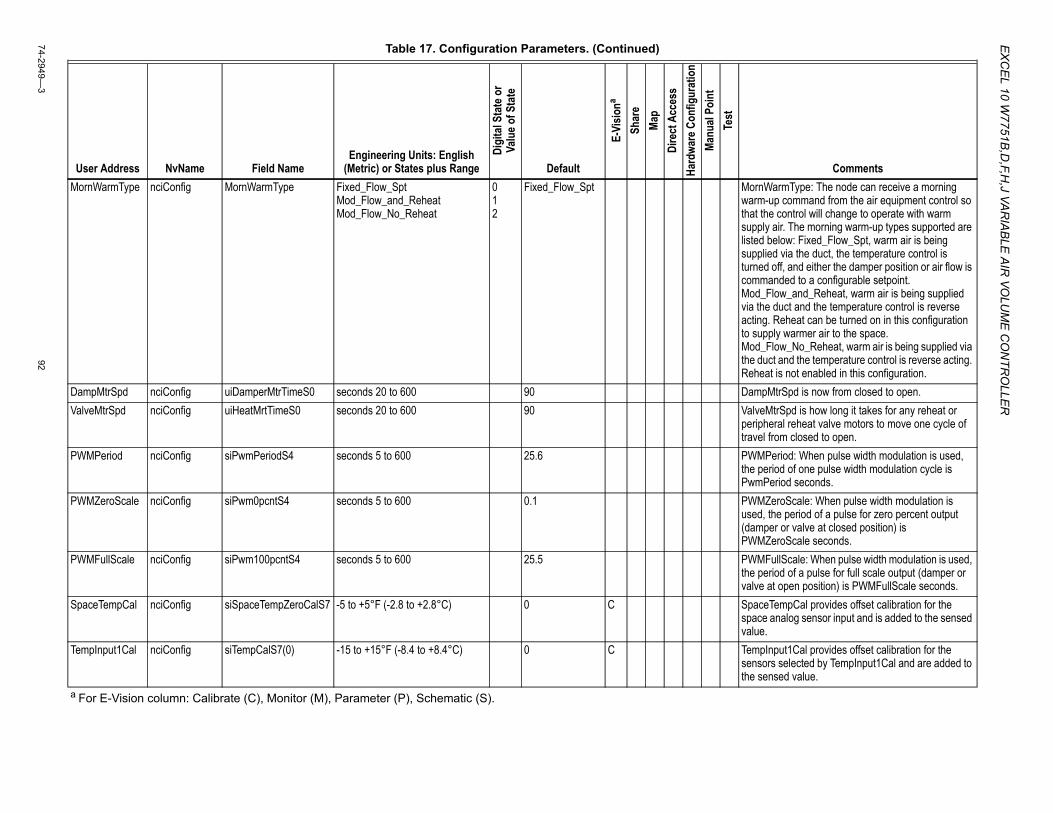
EX
CE
L 10 W7751B
,D,F,H
,J VAR
IAB
LE A
IR VO
LUM
E C
ON
TRO
LLER
74-2949—3
92
MornWarmType nciConfig MornWarmType Fixed_Flow_Spt Mod_Flow_and_Reheat Mod_Flow_No_Reheat
0 1 2
Fixed_Flow_Spt MornWarmType: The node can receive a morning warm-up command from the air equipment control so that the control will change to operate with warm supply air. The morning warm-up types supported are listed below: Fixed_Flow_Spt, warm air is being supplied via the duct, the temperature control is turned off, and either the damper position or air flow is commanded to a configurable setpoint. Mod_Flow_and_Reheat, warm air is being supplied via the duct and the temperature control is reverse acting. Reheat can be turned on in this configuration to supply warmer air to the space. Mod_Flow_No_Reheat, warm air is being supplied via the duct and the temperature control is reverse acting. Reheat is not enabled in this configuration.
DampMtrSpd nciConfig uiDamperMtrTimeS0 seconds 20 to 600 90 DampMtrSpd is now from closed to open.ValveMtrSpd nciConfig uiHeatMrtTimeS0 seconds 20 to 600 90 ValveMtrSpd is how long it takes for any reheat or
peripheral reheat valve motors to move one cycle of travel from closed to open.
PWMPeriod nciConfig siPwmPeriodS4 seconds 5 to 600 25.6 PWMPeriod: When pulse width modulation is used, the period of one pulse width modulation cycle is PwmPeriod seconds.
PWMZeroScale nciConfig siPwm0pcntS4 seconds 5 to 600 0.1 PWMZeroScale: When pulse width modulation is used, the period of a pulse for zero percent output (damper or valve at closed position) is PWMZeroScale seconds.
PWMFullScale nciConfig siPwm100pcntS4 seconds 5 to 600 25.5 PWMFullScale: When pulse width modulation is used, the period of a pulse for full scale output (damper or valve at open position) is PWMFullScale seconds.
SpaceTempCal nciConfig siSpaceTempZeroCalS7 -5 to +5°F (-2.8 to +2.8°C) 0 C SpaceTempCal provides offset calibration for the space analog sensor input and is added to the sensed value.
TempInput1Cal nciConfig siTempCalS7(0) -15 to +15°F (-8.4 to +8.4°C) 0 C TempInput1Cal provides offset calibration for the sensors selected by TempInput1Cal and are added to the sensed value.
Table 17. Configuration Parameters. (Continued)
User Address NvName Field NameEngineering Units: English
(Metric) or States plus Range
Digi
tal S
tate
or
Valu
e of S
tate
Default
E-Vi
siona
Shar
eMa
pDi
rect
Acc
ess
Hard
ware
Con
figur
atio
nMa
nual
Poin
tTe
st
Comments
a For E-Vision column: Calibrate (C), Monitor (M), Parameter (P), Schematic (S).
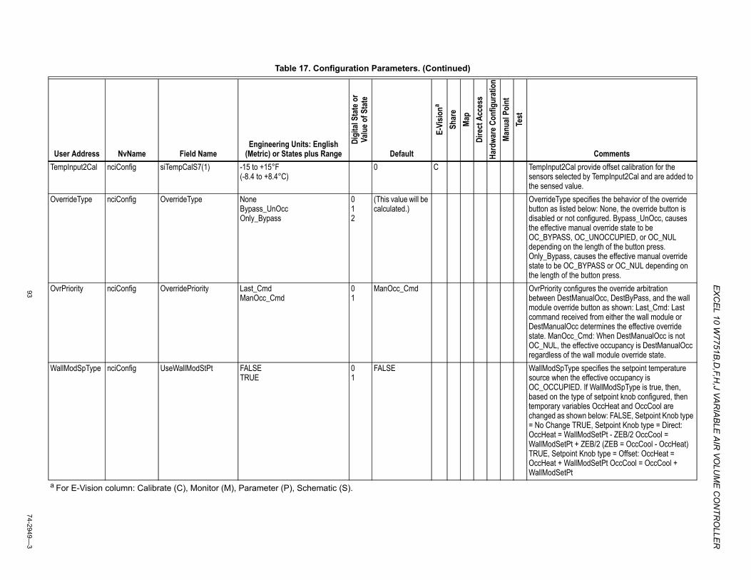
EX
CEL 10 W
7751B,D
,F,H,J VA
RIA
BLE
AIR
VOLU
ME
CO
NTR
OLLE
R
9374-2949—
3
TempInput2Cal nciConfig siTempCalS7(1) -15 to +15°F (-8.4 to +8.4°C)
0 C TempInput2Cal provide offset calibration for the sensors selected by TempInput2Cal and are added to the sensed value.
OverrideType nciConfig OverrideType None Bypass_UnOcc Only_Bypass
0 1 2
(This value will be calculated.)
OverrideType specifies the behavior of the override button as listed below: None, the override button is disabled or not configured. Bypass_UnOcc, causes the effective manual override state to be OC_BYPASS, OC_UNOCCUPIED, or OC_NUL depending on the length of the button press. Only_Bypass, causes the effective manual override state to be OC_BYPASS or OC_NUL depending on the length of the button press.
OvrPriority nciConfig OverridePriority Last_Cmd ManOcc_Cmd
0 1
ManOcc_Cmd OvrPriority configures the override arbitration between DestManualOcc, DestByPass, and the wall module override button as shown: Last_Cmd: Last command received from either the wall module or DestManualOcc determines the effective override state. ManOcc_Cmd: When DestManualOcc is not OC_NUL, the effective occupancy is DestManualOcc regardless of the wall module override state.
WallModSpType nciConfig UseWallModStPt FALSE TRUE
0 1
FALSE WallModSpType specifies the setpoint temperature source when the effective occupancy is OC_OCCUPIED. If WallModSpType is true, then, based on the type of setpoint knob configured, then temporary variables OccHeat and OccCool are changed as shown below: FALSE, Setpoint Knob type = No Change TRUE, Setpoint Knob type = Direct: OccHeat = WallModSetPt - ZEB/2 OccCool = WallModSetPt + ZEB/2 (ZEB = OccCool - OccHeat) TRUE, Setpoint Knob type = Offset: OccHeat = OccHeat + WallModSetPt OccCool = OccCool + WallModSetPt
Table 17. Configuration Parameters. (Continued)
User Address NvName Field NameEngineering Units: English
(Metric) or States plus Range
Digi
tal S
tate
or
Valu
e of S
tate
Default
E-Vi
siona
Shar
eMa
pDi
rect
Acc
ess
Hard
ware
Con
figur
atio
nMa
nual
Poin
tTe
st
Comments
a For E-Vision column: Calibrate (C), Monitor (M), Parameter (P), Schematic (S).
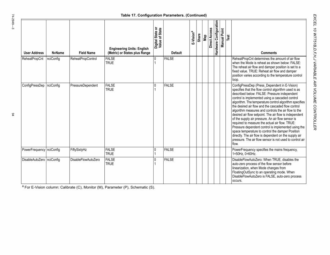
EX
CE
L 10 W7751B
,D,F,H
,J VAR
IAB
LE A
IR VO
LUM
E C
ON
TRO
LLER
74-2949—3
94
ReheatPropCnt nciConfig ReheatPropControl FALSE TRUE
0 1
FALSE ReheatPropCnt determines the amount of air flow when the Mode is reheat as shown below: FALSE: The reheat air flow and damper position is set to a fixed value. TRUE: Reheat air flow and damper position varies according to the temperature control loop.
ConfigPressDep nciConfig PressureDependent FALSE TRUE
0 1
FALSE ConfigPressDep (Press_Dependent in E-Vision) specifies that the flow control algorithm used is as described below: FALSE: Pressure independent control is implemented using a cascaded control algorithm. The temperature control algorithm specifies the desired air flow and the cascaded flow control algorithm measures and controls the air flow to the desired air flow setpoint. The air flow is independent of the supply air pressure. An air flow sensor is required to measure the actual air flow. TRUE: Pressure dependent control is implemented using the space temperature to control the damper Position directly. The air flow is dependent on the supply air pressure. The air flow sensor is not used to control air flow.
PowerFrequency nciConfig FiftySixtyHz FALSE TRUE
0 1
FALSE PowerFrequency specifies the mains frequency, 1=50Hz, 0=60Hz.
DisableAutoZero nciConfig DisableFlowAutoZero FALSE TRUE
0 1
FALSE DisableFlowAutoZero: When TRUE, disables the auto-zero process of the flow sensor before linearization, when Mode changes from FloatingOutSync to an operating mode. When DisableFlowAutoZero is FALSE, auto-zero process occurs.
Table 17. Configuration Parameters. (Continued)
User Address NvName Field NameEngineering Units: English
(Metric) or States plus Range
Digi
tal S
tate
or
Valu
e of S
tate
Default
E-Vi
siona
Shar
eMa
pDi
rect
Acc
ess
Hard
ware
Con
figur
atio
nMa
nual
Poin
tTe
st
Comments
a For E-Vision column: Calibrate (C), Monitor (M), Parameter (P), Schematic (S).
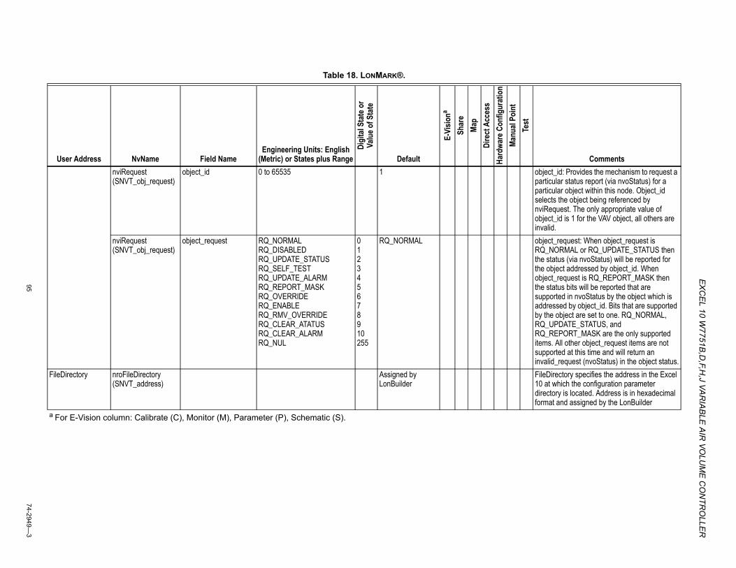
EX
CEL 10 W
7751B,D
,F,H,J VA
RIA
BLE
AIR
VOLU
ME
CO
NTR
OLLE
R
9574-2949—
3
Table 18. LONMARK®.
User Address NvName Field NameEngineering Units: English
(Metric) or States plus Range
Digi
tal S
tate
or
Valu
e of S
tate
Default
E-Vi
siona
Shar
eMa
pDi
rect
Acc
ess
Hard
ware
Con
figur
atio
nMa
nual
Poin
tTe
st
CommentsnviRequest (SNVT_obj_request)
object_id 0 to 65535 1 object_id: Provides the mechanism to request a particular status report (via nvoStatus) for a particular object within this node. Object_id selects the object being referenced by nviRequest. The only appropriate value of object_id is 1 for the VAV object, all others are invalid.
nviRequest(SNVT_obj_request)
object_request RQ_NORMALRQ_DISABLEDRQ_UPDATE_STATUSRQ_SELF_TESTRQ_UPDATE_ALARMRQ_REPORT_MASKRQ_OVERRIDERQ_ENABLERQ_RMV_OVERRIDERQ_CLEAR_ATATUSRQ_CLEAR_ALARMRQ_NUL
012345678910255
RQ_NORMAL object_request: When object_request is RQ_NORMAL or RQ_UPDATE_STATUS then the status (via nvoStatus) will be reported for the object addressed by object_id. When object_request is RQ_REPORT_MASK then the status bits will be reported that are supported in nvoStatus by the object which is addressed by object_id. Bits that are supported by the object are set to one. RQ_NORMAL, RQ_UPDATE_STATUS, and RQ_REPORT_MASK are the only supported items. All other object_request items are not supported at this time and will return an invalid_request (nvoStatus) in the object status.
FileDirectory nroFileDirectory (SNVT_address)
Assigned by LonBuilder
FileDirectory specifies the address in the Excel 10 at which the configuration parameter directory is located. Address is in hexadecimal format and assigned by the LonBuilder
a For E-Vision column: Calibrate (C), Monitor (M), Parameter (P), Schematic (S).
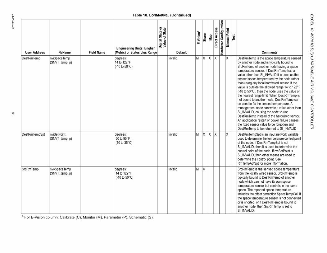
EX
CE
L 10 W7751B
,D,F,H
,J VAR
IAB
LE A
IR VO
LUM
E C
ON
TRO
LLER
74-2949—3
96
DestRmTemp nviSpaceTemp (SNVT_temp_p)
degrees: 14 to 122°F (-10 to 50°C)
Invalid M X X X X DestRmTemp is the space temperature sensed by another node and is typically bound to SrcRmTemp of another node having a space temperature sensor. If DestRmTemp has a value other than SI_INVALID it is used as the sensed space temperature by the node rather than using any local hardwired sensor. If the value is outside the allowed range 14 to 122°F (-10 to 50°C), then the node uses the value of the nearest range limit. When DestRmTemp is not bound to another node, DestRmTemp can be used to fix the sensed temperature. A management node can write a value other than SI_INVALID, causing the node to use DestRmTemp instead of the hardwired sensor. An application restart or power failure causes the fixed sensor value to be forgotten and DestRmTemp to be returned to SI_INVALID
DestRmTempSpt nviSetPoint (SNVT_temp_p)
degrees: 50 to 95°F (10 to 35°C)
Invalid M X X X X DestRmTempSpt is an input network variable used to determine the temperature control point of the node. If DestRmTempSpt is not SI_INVALID, then it is used to determine the control point of the node. If nviSetPoint is SI_INVALID, then other means are used to determine the control point. See RmTempActSpt for more information.
SrcRmTemp nvoSpaceTemp (SNVT_temp_p)
degrees: 14 to 122°F (-10 to 50°C)
Invalid M X SrcRmTemp is the sensed space temperature from the locally wired sensor. SrcRmTemp is typically bound to DestRmTemp of another node which can not have its own space temperature sensor but controls in the same space. The reported space temperature includes the offset correction SpaceTempCal. If the space temperature sensor is not connected or is shorted, or if DestRmTemp is bound to another node, then SrcRmTemp is set to SI_INVALID.
Table 18. LONMARK®. (Continued)
User Address NvName Field NameEngineering Units: English
(Metric) or States plus Range
Digi
tal S
tate
or
Valu
e of S
tate
Default
E-Vi
siona
Shar
eMa
pDi
rect
Acc
ess
Hard
ware
Con
figur
atio
nMa
nual
Poin
tTe
st
Comments
a For E-Vision column: Calibrate (C), Monitor (M), Parameter (P), Schematic (S).

EX
CEL 10 W
7751B,D
,F,H,J VA
RIA
BLE
AIR
VOLU
ME
CO
NTR
OLLE
R
9774-2949—
3
SrcUnitStatus nvoUnitStatus (SNVT_hvac_status)
mode HVAC_AUTOHVAC_HEATHVAC_MRNG_WRMUPHVAC_COOLHVAC_NIGHT_PURGEHVAC_PRE_COOLHVAC_OFFHVAC_TESTHVAC_EMERG_HEATHVAC_FAN_ONLYHVAC_NUL
0123456789255
HVAC_OFF X SrcUnitStatus is set according to the StatusMode. If StatusMode is Pressurize, DePressurize, TrackFlow, Flowt_Out_Sync, or FreezeProtect the mode is set to HVAC_NUL which indicates that the node is in a mode not supported by the SNVT_hvac_mode data type. If StatusMode is HEAT or REHEAT, then the mode is set to HVAC_HEAT, which indicates that heating energy is being supplied to the controlled space. If StatusMode is COOL, then the mode is set to HVAC_COOL, which indicates that cooling energy is being supplied to the controlled space. If StatusMode is StartUpWait or DISABLED_MODE, then the mode is disabled or off. If StatusMode is MornWarm the mode is set to HVAC_MRNG_WRMUP which indicates that the heated air is being supplied for morning-warm-up. If StatusMode is NightPurge, the mode is set to HVAC_NIGHT_PURGE which indicates that the outside air is being supplied for night purge. If StatusMode is IOTest, FactoryTest, Manual, ManualPos, or ManualFlow the mode is set to HVAC_TEST which indicates that the node is in a manual or test mode. HVAC_AUTO, HVAC_PRE_COOL, HVAC_EMERG_HEAT, and HVAC_FAN_ONLY are not supported.
UnitHeatOutputPri nvoUnitStatus (SNVT_hvac_status)
heat_output_primary percentage 0 to 100 0 UnitHeatOutputPri reports the current percentage of reheat stages or modulating reheat that are turned on. If the reheat type is DualDuctReHeat, UnitHeatOutputPri reports the current percentage of heat requested of the hot duct. When reheat is configured, UnitHeatOutputPri is set to Invalid.
Table 18. LONMARK®. (Continued)
User Address NvName Field NameEngineering Units: English
(Metric) or States plus Range
Digi
tal S
tate
or
Valu
e of S
tate
Default
E-Vi
siona
Shar
eMa
pDi
rect
Acc
ess
Hard
ware
Con
figur
atio
nMa
nual
Poin
tTe
st
Comments
a For E-Vision column: Calibrate (C), Monitor (M), Parameter (P), Schematic (S).
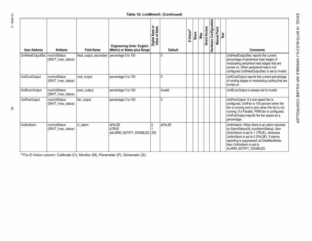
EX
CE
L 10 W7751B
,D,F,H
,J VAR
IAB
LE A
IR VO
LUM
E C
ON
TRO
LLER
74-2949—3
98
UnitHeatOutputSec nvoUnitStatus (SNVT_hvac_status)
heat_output_secondary percentage 0 to 100 0 UnitHeatOutputSec reports the current percentage of peripheral heat stages of modulating peripheral heat stages that are turned on. When peripheral heat is not configured UnitHeatOutputSec is set to Invalid.
UnitCoolOutput nvoUnitStatus (SNVT_hvac_status)
cool_output percentage 0 to 100 0 UnitCoolOutput reports the current percentage of cooling stages or modulating cooling that are turned on.
UnitEconOutput nvoUnitStatus (SNVT_hvac_status)
econ_output percentage 0 to 100 Invalid UnitEconOutput is always set to invalid.
UnitFanOutput nvoUnitStatus (SNVT_hvac_status)
fan_output percentage 0 to 100 0 UnitFanOutput: If a one speed fan is configured, UnitFan is 100 percent when the fan is running and is zero when the fan is not running. If a Parallel_PWM fan is configured, UnitFanOutput reports the fan speed as a percentage.
UnitInAlarm nvoUnitStatus (SNVT_hvac_status)
in_alarm aFALSEaTRUEaALARM_NOTIFY_DISABLED
01255
aFALSE UnitInAlarm: When there is an alarm reported by AlarmStatus(N) (nvoAlarmStatus), then UnitInAlarm is set to 1 (TRUE), otherwise UnitInAlarm is set to 0 (FALSE). If alarms reporting is suppressed via DestManMode, then UnitInAlarm is set to ALARM_NOTIFY_DISABLED.
Table 18. LONMARK®. (Continued)
User Address NvName Field NameEngineering Units: English
(Metric) or States plus Range
Digi
tal S
tate
or
Valu
e of S
tate
Default
E-Vi
siona
Shar
eMa
pDi
rect
Acc
ess
Hard
ware
Con
figur
atio
nMa
nual
Poin
tTe
st
Comments
a For E-Vision column: Calibrate (C), Monitor (M), Parameter (P), Schematic (S).
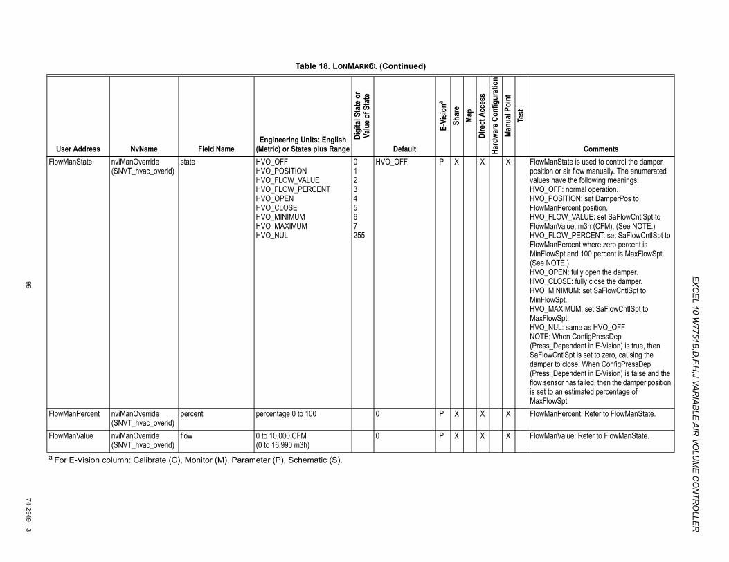
EX
CEL 10 W
7751B,D
,F,H,J VA
RIA
BLE
AIR
VOLU
ME
CO
NTR
OLLE
R
9974-2949—
3
FlowManState nviManOverride (SNVT_hvac_overid)
state HVO_OFFHVO_POSITIONHVO_FLOW_VALUEHVO_FLOW_PERCENTHVO_OPENHVO_CLOSEHVO_MINIMUMHVO_MAXIMUMHVO_NUL
01234567255
HVO_OFF P X X X FlowManState is used to control the damper position or air flow manually. The enumerated values have the following meanings:HVO_OFF: normal operation.HVO_POSITION: set DamperPos to FlowManPercent position.HVO_FLOW_VALUE: set SaFlowCntlSpt to FlowManValue, m3h (CFM). (See NOTE.)HVO_FLOW_PERCENT: set SaFlowCntlSpt to FlowManPercent where zero percent is MinFlowSpt and 100 percent is MaxFlowSpt. (See NOTE.)HVO_OPEN: fully open the damper.HVO_CLOSE: fully close the damper.HVO_MINIMUM: set SaFlowCntlSpt to MinFlowSpt.HVO_MAXIMUM: set SaFlowCntlSpt to MaxFlowSpt.HVO_NUL: same as HVO_OFFNOTE: When ConfigPressDep (Press_Dependent in E-Vision) is true, then SaFlowCntlSpt is set to zero, causing the damper to close. When ConfigPressDep (Press_Dependent in E-Vision) is false and the flow sensor has failed, then the damper position is set to an estimated percentage of MaxFlowSpt.
FlowManPercent nviManOverride (SNVT_hvac_overid)
percent percentage 0 to 100 0 P X X X FlowManPercent: Refer to FlowManState.
FlowManValue nviManOverride (SNVT_hvac_overid)
flow 0 to 10,000 CFM (0 to 16,990 m3h)
0 P X X X FlowManValue: Refer to FlowManState.
Table 18. LONMARK®. (Continued)
User Address NvName Field NameEngineering Units: English
(Metric) or States plus Range
Digi
tal S
tate
or
Valu
e of S
tate
Default
E-Vi
siona
Shar
eMa
pDi
rect
Acc
ess
Hard
ware
Con
figur
atio
nMa
nual
Poin
tTe
st
Comments
a For E-Vision column: Calibrate (C), Monitor (M), Parameter (P), Schematic (S).
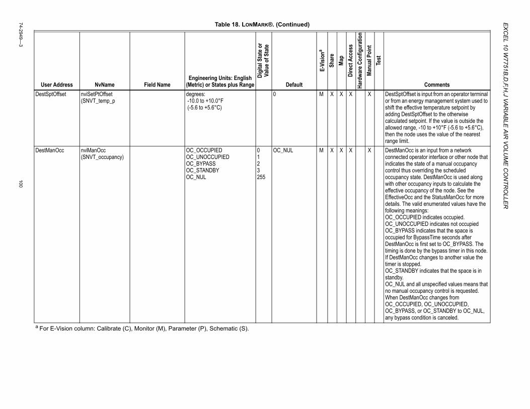
EX
CE
L 10 W7751B
,D,F,H
,J VAR
IAB
LE A
IR VO
LUM
E C
ON
TRO
LLER
74-2949—3
100
DestSptOffset nviSetPtOffset (SNVT_temp_p
degrees: -10.0 to +10.0°F (-5.6 to +5.6°C)
0 M X X X X DestSptOffset is input from an operator terminal or from an energy management system used to shift the effective temperature setpoint by adding DestSptOffset to the otherwise calculated setpoint. If the value is outside the allowed range, -10 to +10°F (-5.6 to +5.6°C), then the node uses the value of the nearest range limit.
DestManOcc nviManOcc (SNVT_occupancy)
OC_OCCUPIEDOC_UNOCCUPIEDOC_BYPASSOC_STANDBYOC_NUL
0123255
OC_NUL M X X X X DestManOcc is an input from a network connected operator interface or other node that indicates the state of a manual occupancy control thus overriding the scheduled occupancy state. DestManOcc is used along with other occupancy inputs to calculate the effective occupancy of the node. See the EffectiveOcc and the StatusManOcc for more details. The valid enumerated values have the following meanings:OC_OCCUPIED indicates occupied.OC_UNOCCUPIED indicates not occupiedOC_BYPASS indicates that the space is occupied for BypassTime seconds after DestManOcc is first set to OC_BYPASS. The timing is done by the bypass timer in this node. If DestManOcc changes to another value the timer is stopped.OC_STANDBY indicates that the space is in standby.OC_NUL and all unspecified values means that no manual occupancy control is requested. When DestManOcc changes from OC_OCCUPIED, OC_UNOCCUPIED, OC_BYPASS, or OC_STANDBY to OC_NUL, any bypass condition is canceled.
Table 18. LONMARK®. (Continued)
User Address NvName Field NameEngineering Units: English
(Metric) or States plus Range
Digi
tal S
tate
or
Valu
e of S
tate
Default
E-Vi
siona
Shar
eMa
pDi
rect
Acc
ess
Hard
ware
Con
figur
atio
nMa
nual
Poin
tTe
st
Comments
a For E-Vision column: Calibrate (C), Monitor (M), Parameter (P), Schematic (S).
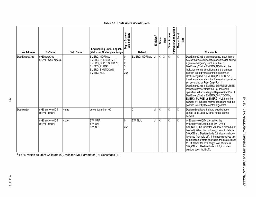
EX
CEL 10 W
7751B,D
,F,H,J VA
RIA
BLE
AIR
VOLU
ME
CO
NTR
OLLE
R
10174-2949—
3
DestEmergCmd nviEmergCmd (SNVT_hvac_emerg)
EMERG_NORMALEMERG_PRESSURIZEEMERG_DEPRESSURIZEEMERG_PURGEEMERG_SHUTDOWNEMERG_NUL
01234255
EMERG_NORMAL M X X X X DestEmergCmd is an emergency input from a device that determines the correct action during a given emergency, such as a fire. If DestEmergCmd is EMERG_NORMAL, this indicates normal conditions and the damper position is set by the control algorithm. If DestEmergCmd is EMERG_PRESSURIZE, then the damper starts the Pressurize operation set according to PressDmprPos. If DestEmergCmd is EMERG_DEPRESSURIZE, then the damper starts the DePressurize operation set according to DepressDmpPos. If DestEmergCmd is EMERG_SHUTDOWN, EMERG_PURGE, or EMERG_NUL then the damper will indicate normal conditions and the position is set by the control algorithm.
DestWndw nviEnergyHoldOff (SNVT_switch)
value percentage 0 to 100 0 M X X X DestWndw allows the hard wired window sensor to be used by other nodes on the network.
nviEnergyHoldOff (SNVT_switch)
state SW_OFFSW_ONSW_NUL
01255
SW_NUL M X X X nviEnergyHoldOff.state: When the nviEnergyHoldOff.state is SW_OFF or SW_NULL, this indicates window is closed (not hold-off). When the nviEnergyHoldOff.state is SW_ON and DestWndw is 0, indicates window is closed (not hold-off). If the node receives this combination of state and value, then state is set to Off. When the nviEnergyHoldOff.state is SW_ON and DestWndw is not 0, indicates window open (hold-off).
Table 18. LONMARK®. (Continued)
User Address NvName Field NameEngineering Units: English
(Metric) or States plus Range
Digi
tal S
tate
or
Valu
e of S
tate
Default
E-Vi
siona
Shar
eMa
pDi
rect
Acc
ess
Hard
ware
Con
figur
atio
nMa
nual
Poin
tTe
st
Comments
a For E-Vision column: Calibrate (C), Monitor (M), Parameter (P), Schematic (S).
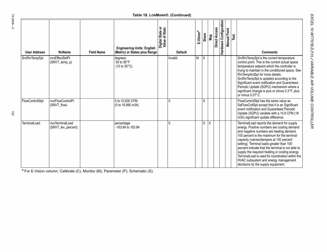
EX
CE
L 10 W7751B
,D,F,H
,J VAR
IAB
LE A
IR VO
LUM
E C
ON
TRO
LLER
74-2949—3
102
SrcRmTempSpt nvoEffectSetPt (SNVT_temp_p)
degrees: 50 to 95°F (10 to 35°C)
Invalid M X SrcRmTempSpt is the current temperature control point. This is the current actual space temperature setpoint which the controller is trying to maintain in the conditioned space. See RmTempActSpt for more details. SrcRmTempSpt is updated according to the Significant event notification and Guaranteed Periodic Update (SGPU) mechanism where a significant change is plus or minus 0.3°F, plus or minus 0.07°C.
FlowControlStpt nvoFlowControlPt (SNVT_flow)
0 to 10,000 CFM (0 to 16,990 m3h)
0 X FlowControlStpt has the same value as SaFlowCntlSpt except that it is an Significant event notification and Guaranteed Periodic Update (SGPU) variable with a 10.6 CFM (18 m3h) significant update difference.
TerminalLoad nvoTerminalLoad (SNVT_lev_percent)
percentage -163.84 to 163.84
0 X X TerminalLoad reports the demand for supply energy. Positive numbers are cooling demand and negative numbers are heating demand. 100 percent is the maximum for the terminal capacity (valves/dampers at 100 percent setting). Terminal loads greater than 100 percent indicate that the terminal is not able to supply the required heating or cooling energy. TerminalLoad is used for coordination within the HVAC subsystem and energy management decisions by the supply equipment.
Table 18. LONMARK®. (Continued)
User Address NvName Field NameEngineering Units: English
(Metric) or States plus Range
Digi
tal S
tate
or
Valu
e of S
tate
Default
E-Vi
siona
Shar
eMa
pDi
rect
Acc
ess
Hard
ware
Con
figur
atio
nMa
nual
Poin
tTe
st
Comments
a For E-Vision column: Calibrate (C), Monitor (M), Parameter (P), Schematic (S).
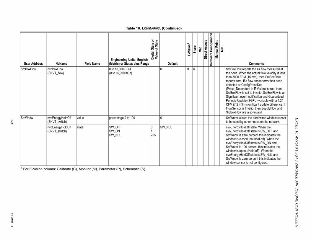
EX
CEL 10 W
7751B,D
,F,H,J VA
RIA
BLE
AIR
VOLU
ME
CO
NTR
OLLE
R
10374-2949—
3
SrcBoxFlow nvoBoxFlow (SNVT_flow)
0 to 10,000 CFM (0 to 16,990 m3h)
0 M X SrcBoxFlow reports the air flow measured at the node. When the actual flow velocity is less than 3000 FPM (15 m/s), then SrcBoxFlow reports zero. If a flow sensor error has been detected or ConfigPressDep (Press_Dependent in E-Vision) is true, then SrcBoxFlow is set to Invalid. SrcBoxFlow is an Significant event notification and Guaranteed Periodic Update (SGPU) variable with a 4.24 CFM (7.2 m3h) significant update difference. If FlowSensor is Invalid, then SupplyFlow and SrcBoxFlow are also Invalid.
SrcWndw nvoEnergyHoldOff (SNVT_switch)
value percentage 0 to 100 0 SrcWndw allows the hard wired window sensor to be used by other nodes on the network.
nvoEnergyHoldOff (SNVT_switch)
state SW_OFFSW_ONSW_NUL
01255
SW_NUL nvoEnergyHoldOff.state: When the nvoEnergyHoldOff.state is SW_OFF and SrcWndw is zero percent this indicates the window is closed (not hold-off). When the nvoEnergyHoldOff.state is SW_ON and SrcWndw is 100 percent this indicates the window is open. (Hold-off). When the nvoEnergyHoldOff.state is SW_NUL and SrcWndw is zero percent this indicates the window sensor is not configured.
Table 18. LONMARK®. (Continued)
User Address NvName Field NameEngineering Units: English
(Metric) or States plus Range
Digi
tal S
tate
or
Valu
e of S
tate
Default
E-Vi
siona
Shar
eMa
pDi
rect
Acc
ess
Hard
ware
Con
figur
atio
nMa
nual
Poin
tTe
st
Comments
a For E-Vision column: Calibrate (C), Monitor (M), Parameter (P), Schematic (S).
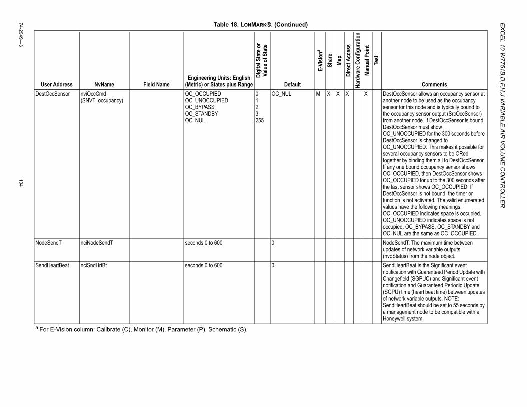
EX
CE
L 10 W7751B
,D,F,H
,J VAR
IAB
LE A
IR VO
LUM
E C
ON
TRO
LLER
74-2949—3
104
DestOccSensor nviOccCmd (SNVT_occupancy)
OC_OCCUPIED OC_UNOCCUPIED OC_BYPASS OC_STANDBY OC_NUL
0 1 2 3 255
OC_NUL M X X X X DestOccSensor allows an occupancy sensor at another node to be used as the occupancy sensor for this node and is typically bound to the occupancy sensor output (SrcOccSensor) from another node. If DestOccSensor is bound, DestOccSensor must show OC_UNOCCUPIED for the 300 seconds before DestOccSensor is changed to OC_UNOCCUPIED. This makes it possible for several occupancy sensors to be ORed together by binding them all to DestOccSensor. If any one bound occupancy sensor shows OC_OCCUPIED, then DestOccSensor shows OC_OCCUPIED for up to the 300 seconds after the last sensor shows OC_OCCUPIED. If DestOccSensor is not bound, the timer or function is not activated. The valid enumerated values have the following meanings: OC_OCCUPIED indicates space is occupied. OC_UNOCCUPIED indicates space is not occupied. OC_BYPASS, OC_STANDBY and OC_NUL are the same as OC_OCCUPIED.
NodeSendT nciNodeSendT seconds 0 to 600 0 NodeSendT: The maximum time between updates of network variable outputs (nvoStatus) from the node object.
SendHeartBeat nciSndHrtBt seconds 0 to 600 0 SendHeartBeat is the Significant event notification with Guaranteed Period Update with Changefield (SGPUC) and Significant event notification and Guaranteed Periodic Update (SGPU) time (heart beat time) between updates of network variable outputs. NOTE: SendHeartBeat should be set to 55 seconds by a management node to be compatible with a Honeywell system.
Table 18. LONMARK®. (Continued)
User Address NvName Field NameEngineering Units: English
(Metric) or States plus Range
Digi
tal S
tate
or
Valu
e of S
tate
Default
E-Vi
siona
Shar
eMa
pDi
rect
Acc
ess
Hard
ware
Con
figur
atio
nMa
nual
Poin
tTe
st
Comments
a For E-Vision column: Calibrate (C), Monitor (M), Parameter (P), Schematic (S).
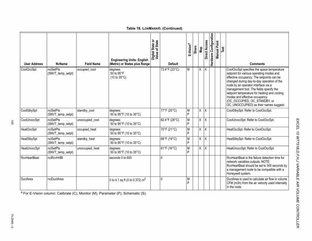
EX
CEL 10 W
7751B,D
,F,H,J VA
RIA
BLE
AIR
VOLU
ME
CO
NTR
OLLE
R
10574-2949—
3
CoolOccSpt nciSetPts (SNVT_temp_setpt)
occupied_cool degrees: 50 to 95°F (10 to 35°C)
73.4°F (23°C) M X X CoolOccSpt specifies the space temperature setpoint for various operating modes and effective occupancy. The setpoints can be changed during day-to-day operation of the node by an operator interface via a management tool. The fields specify the setpoint temperature for heating and cooling modes and effective occupancy (OC_OCCUPIED, OC_STANDBY, or OC_UNOCCUPIED) as their names suggest.
CoolStbySpt nciSetPts (SNVT_temp_setpt)
standby_cool degrees: 50 to 95°F (10 to 35°C)
77°F (25°C) MP
X X CoolStbySpt: Refer to CoolOccSpt.
CoolUnoccSpt nciSetPts (SNVT_temp_setpt)
unoccupied_cool degrees: 50 to 95°F (10 to 35°C)
82.4°F (28°C) MP
X X CoolUnoccSpt: Refer to CoolOccSpt.
HeatOccSpt nciSetPts (SNVT_temp_setpt)
occupied_heat degrees: 50 to 95°F (10 to 35°C)
70°F (21°C) MP
X X HeatOccSpt: Refer to CoolOccSpt.
HeatStbySpt nciSetPts (SNVT_temp_setpt)
standby_heat degrees: 50 to 95°F (10 to 35°C)
66°F (19°C) MP
X X HeatStbySpt: Refer to CoolOccSpt.
HeatUnoccSpt nciSetPts (SNVT_temp_setpt)
unoccupied_heat degrees: 50 to 95°F (10 to 35°C)
61°F (16°C) MP
X X HeatUnoccSpt: Refer to CoolOccSpt.
RcvHeartBeat nciRcvHrtBt seconds 0 to 600 0 RcvHeartBeat is the failure detection time for network variables outputs. NOTE: RcvHeartBeat should be set to 300 seconds by a management node to be compatible with a Honeywell system.
DuctArea nciDuctArea 0 to 4.1 sq ft (0 to 0.372) m2 0 MP
DuctArea is used to calculate air flow in volume CFM (m3h) from the air velocity used internally in the node.
Table 18. LONMARK®. (Continued)
User Address NvName Field NameEngineering Units: English
(Metric) or States plus Range
Digi
tal S
tate
or
Valu
e of S
tate
Default
E-Vi
siona
Shar
eMa
pDi
rect
Acc
ess
Hard
ware
Con
figur
atio
nMa
nual
Poin
tTe
st
Comments
a For E-Vision column: Calibrate (C), Monitor (M), Parameter (P), Schematic (S).
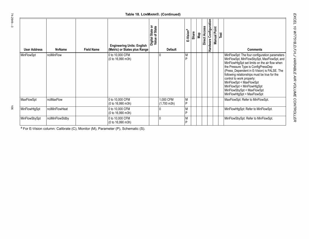
EX
CE
L 10 W7751B
,D,F,H
,J VAR
IAB
LE A
IR VO
LUM
E C
ON
TRO
LLER
74-2949—3
106
MinFlowSpt nciMinFlow 0 to 10,000 CFM (0 to 16,990 m3h)
0 MP
MinFlowSpt: The four configuration parameters MinFlowSpt, MinFlowSbySpt, MaxFlowSpt, and MinFlowHtgSpt set limits on the air flow when the Pressure Type is ConfigPressDep (Press_Dependent in E-Vision) is FALSE. The following relationships must be true for the control to work properly:MinFlowSpt < MaxFlowSptMinFlowSpt < MinFlowHtgSptMinFlowSbySpt < MaxFlowSptMinFlowHtgSpt < MaxFlowSpt
MaxFlowSpt nciMaxFlow 0 to 10,000 CFM (0 to 16,990 m3h)
1,000 CFM (1,700 m3h)
MP
MaxFlowSpt: Refer to MinFlowSpt.
MinFlowHtgSpt nciMinFlowHeat 0 to 10,000 CFM (0 to 16,990 m3h)
0 MP
MinFlowHtgSpt: Refer to MinFlowSpt.
MinFlowSbySpt nciMinFlowStdby 0 to 10,000 CFM (0 to 16,990 m3h)
0 MP
MinFlowSbySpt: Refer to MinFlowSpt.
Table 18. LONMARK®. (Continued)
User Address NvName Field NameEngineering Units: English
(Metric) or States plus Range
Digi
tal S
tate
or
Valu
e of S
tate
Default
E-Vi
siona
Shar
eMa
pDi
rect
Acc
ess
Hard
ware
Con
figur
atio
nMa
nual
Poin
tTe
st
Comments
a For E-Vision column: Calibrate (C), Monitor (M), Parameter (P), Schematic (S).
EX
CEL 10 W
7751B,D
,F,H,J VA
RIA
BLE
AIR
VOLU
ME
CO
NTR
OLLE
R
10774-2949—
3
Table 19. Direct Access and Special Points.
User Address NvName Field Name
Engineering Units: English (Metric) or States plus Range
Digi
tal S
tate
or
Valu
e of S
tate
Default
E-Vi
siona
Shar
eMa
pDi
rect
Acc
ess
Hard
ware
Con
figur
atio
nMa
nual
Poin
tTe
st
CommentsDestManMode nviManualMode MODE_ENABLE
MODE_DISABLEMODE_MANUALSUPPRESS_ALARMSUNSUPPRESS_ALARMS
01234
MODE_ENABLE M X X X X DestManMode is an input which is used to disable the Excel 10s control algorithms and to manually set the physical outputs. DestManMode remains unchanged until another mode has been commanded or an application restart has been performed. See StatusMode for more details. The valid enumerated values are:MODE_ENABLE enables the node so that the control algorithm determines the operating mode, and controls the physical outputs. MODE_ENABLE is the default state after power restore or application restart. If the mode were MODE_MANUAL and DestManMode is set to MODE_ENABLE, the node then goes through application_restart.MODE_DISABLE sets the node to the DISABLED mode. The alarm NODE_DISABLED is initiated, all control loops are disabled, and the physical outputs are turned off. The physical inputs, network variable inputs, and network variable outputs are still functioning when the node is in the DISABLED mode.MODE_MANUAL sets the node into the MANUAL mode. The alarm NODE_DISABLED_ALARM is initiated, all control loops are disabled, and the physical outputs are controlled manually as commanded by nviManValue. The nodes configuration variables and nviManValue are used to set valves, dampers, and/or digital output to the desired manual positions or state(s). The physical inputs, network variable inputs, and network variable outputs are still functioning when the node is in the MODE_MANUAL mode. SUPPRESS_ALARMS causes AlarmType to be set to ALARM_NOTIFY_DISABLED, and AlarmLog0 through AlarmLog4 to no longer record alarms. If alarms are suppressed, UNSUPPRESS_ALARMS causes AlarmType and AlarmLog0 through AlarmLog4 to be returned to reporting alarms. See AlarmType for more details. All unspecified values are the same as MODE_ENABLE.
a For E-Vision column: Calibrate (C), Monitor (M), Parameter (P), Schematic (S).
EX
CE
L 10 W7751B
,D,F,H
,J VAR
IAB
LE A
IR VO
LUM
E C
ON
TRO
LLER
74-2949—3
108
ManFactoryTest nviManValue ManFactoryTest NormalOpTest1OnTest2OnTest3OnTest4OnTest5OnTest6OnTest7OnTest8OnTestAllOffTestAllOnTestAllDisabledTestScaleAmpOff
0123456789101112
NormalOp X ManFactoryTest: The node (Mode) and the physical output(s) energized for various values of ManFactoryTest are described as below:NormalOp or unspecified value and node (Mode) is determined by other network variables, then the physical outputs are controlled by algorithms or other fields in ManFactoryTest. (This test is only used when the controller is specifically in the Factory Test Mode, (factory only) this mode can not be accessed by (XI 584) Direct Access or E-Vision.Test1On: D01 is energized.Test2On: D02 is energized.Test3On: D03 is energized.Test4On: D04 is energized.Test5On: D05 is energized.Test6On: D06 is energized.Test7On: D07 is energized.Test8On: D08 is energized.TestAllOff: no output is energized.TestAllOn: all outputs are energized.TestAllDisabled: All output bits are turned on but the output drivers are disabled causing the outputs to be off. This checks the driver Disable function of the hardware.TestScaleAmpOff: the scaling amplifier between the sensor and the A/D is turned off so that the amplified sensor voltage can be directly measured by the A/D converter or a voltmeter connected to a circuit board Test point. During FactoryTest Mode, all control loops are disabled, and the physical outputs are controlled manually as commanded by nviManValue on a bit by bit basis ignoring the nodes configuration variables. The physical inputs, network variable inputs, and network variable outputs are still functioning when the node is in the FactoryTest Mode.
ManDamp nviManValue ManDamperPos percentage 0 to 100 0 X ManDamp: During Manual Mode, ManDamp sets the damper position to the specified position. If ManDamp is 0 or 100 percent, the motor is overdriven for a period longer than the motor time to ensure that it is at the end of travel.
Table 19. Direct Access and Special Points. (Continued)
User Address NvName Field Name
Engineering Units: English (Metric) or States plus Range
Digi
tal S
tate
or
Valu
e of S
tate
Default
E-Vi
siona
Shar
eMa
pDi
rect
Acc
ess
Hard
ware
Con
figur
atio
nMa
nual
Poin
tTe
st
Comments
a For E-Vision column: Calibrate (C), Monitor (M), Parameter (P), Schematic (S).
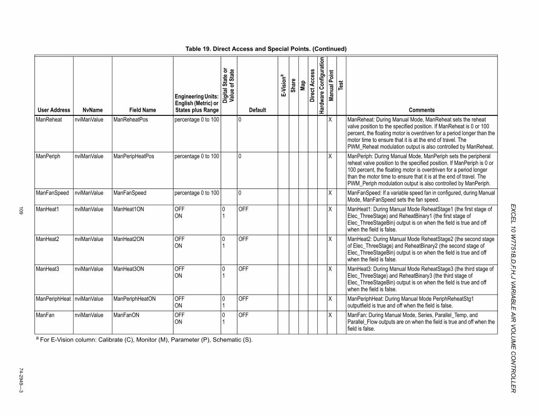
EX
CEL 10 W
7751B,D
,F,H,J VA
RIA
BLE
AIR
VOLU
ME
CO
NTR
OLLE
R
10974-2949—
3
ManReheat nviManValue ManReheatPos percentage 0 to 100 0 X ManReheat: During Manual Mode, ManReheat sets the reheat valve position to the specified position. If ManReheat is 0 or 100 percent, the floating motor is overdriven for a period longer than the motor time to ensure that it is at the end of travel. The PWM_Reheat modulation output is also controlled by ManReheat.
ManPeriph nviManValue ManPeripHeatPos percentage 0 to 100 0 X ManPeriph: During Manual Mode, ManPeriph sets the peripheral reheat valve position to the specified position. If ManPeriph is 0 or 100 percent, the floating motor is overdriven for a period longer than the motor time to ensure that it is at the end of travel. The PWM_Periph modulation output is also controlled by ManPeriph.
ManFanSpeed nviManValue ManFanSpeed percentage 0 to 100 0 X ManFanSpeed: If a variable speed fan in configured, during Manual Mode, ManFanSpeed sets the fan speed.
ManHeat1 nviManValue ManHeat1ON OFFON
01
OFF X ManHeat1: During Manual Mode ReheatStage1 (the first stage of Elec_ThreeStage) and ReheatBinary1 (the first stage of Elec_ThreeStageBin) output is on when the field is true and off when the field is false.
ManHeat2 nviManValue ManHeat2ON OFFON
01
OFF X ManHeat2: During Manual Mode ReheatStage2 (the second stage of Elec_ThreeStage) and ReheatBinary2 (the second stage of Elec_ThreeStageBin) output is on when the field is true and off when the field is false.
ManHeat3 nviManValue ManHeat3ON OFFON
01
OFF X ManHeat3: During Manual Mode ReheatStage3 (the third stage of Elec_ThreeStage) and ReheatBinary3 (the third stage of Elec_ThreeStageBin) output is on when the field is true and off when the field is false.
ManPeriphHeat nviManValue ManPeriphHeatON OFFON
01
OFF X ManPeriphHeat: During Manual Mode PeriphReheatStg1 outputfield is true and off when the field is false.
ManFan nviManValue ManFanON OFFON
01
OFF X ManFan: During Manual Mode, Series, Parallel_Temp, and Parallel_Flow outputs are on when the field is true and off when the field is false.
Table 19. Direct Access and Special Points. (Continued)
User Address NvName Field Name
Engineering Units: English (Metric) or States plus Range
Digi
tal S
tate
or
Valu
e of S
tate
Default
E-Vi
siona
Shar
eMa
pDi
rect
Acc
ess
Hard
ware
Con
figur
atio
nMa
nual
Poin
tTe
st
Comments
a For E-Vision column: Calibrate (C), Monitor (M), Parameter (P), Schematic (S).
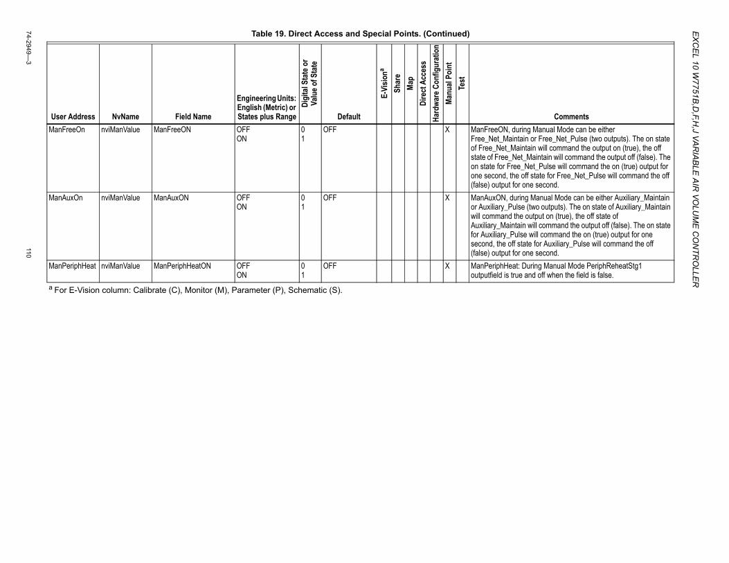
EX
CE
L 10 W7751B
,D,F,H
,J VAR
IAB
LE A
IR VO
LUM
E C
ON
TRO
LLER
74-2949—3
110
ManFreeOn nviManValue ManFreeON OFFON
01
OFF X ManFreeON, during Manual Mode can be either Free_Net_Maintain or Free_Net_Pulse (two outputs). The on state of Free_Net_Maintain will command the output on (true), the off state of Free_Net_Maintain will command the output off (false). The on state for Free_Net_Pulse will command the on (true) output for one second, the off state for Free_Net_Pulse will command the off (false) output for one second.
ManAuxOn nviManValue ManAuxON OFFON
01
OFF X ManAuxON, during Manual Mode can be either Auxiliary_Maintain or Auxiliary_Pulse (two outputs). The on state of Auxiliary_Maintain will command the output on (true), the off state of Auxiliary_Maintain will command the output off (false). The on state for Auxiliary_Pulse will command the on (true) output for one second, the off state for Auxiliary_Pulse will command the off (false) output for one second.
ManPeriphHeat nviManValue ManPeriphHeatON OFFON
01
OFF X ManPeriphHeat: During Manual Mode PeriphReheatStg1 outputfield is true and off when the field is false.
Table 19. Direct Access and Special Points. (Continued)
User Address NvName Field Name
Engineering Units: English (Metric) or States plus Range
Digi
tal S
tate
or
Valu
e of S
tate
Default
E-Vi
siona
Shar
eMa
pDi
rect
Acc
ess
Hard
ware
Con
figur
atio
nMa
nual
Poin
tTe
st
Comments
a For E-Vision column: Calibrate (C), Monitor (M), Parameter (P), Schematic (S).
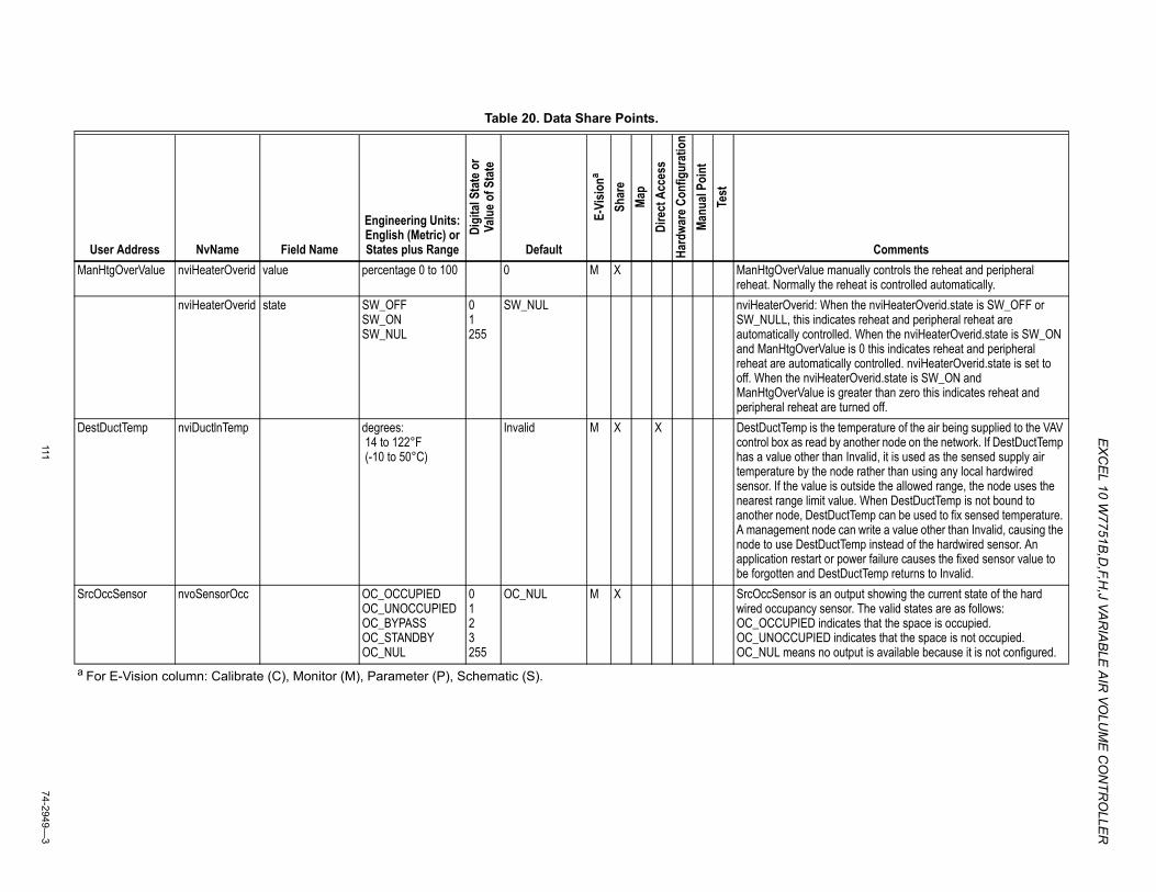
EX
CEL 10 W
7751B,D
,F,H,J VA
RIA
BLE
AIR
VOLU
ME
CO
NTR
OLLE
R
11174-2949—
3
Table 20. Data Share Points.
User Address NvName Field Name
Engineering Units: English (Metric) or States plus Range
Digi
tal S
tate
or
Valu
e of S
tate
Default
E-Vi
siona
Shar
eMa
pDi
rect
Acc
ess
Hard
ware
Con
figur
atio
nMa
nual
Poin
tTe
st
CommentsManHtgOverValue nviHeaterOverid value percentage 0 to 100 0 M X ManHtgOverValue manually controls the reheat and peripheral
reheat. Normally the reheat is controlled automatically.nviHeaterOverid state SW_OFF
SW_ON SW_NUL
01255
SW_NUL nviHeaterOverid: When the nviHeaterOverid.state is SW_OFF or SW_NULL, this indicates reheat and peripheral reheat are automatically controlled. When the nviHeaterOverid.state is SW_ON and ManHtgOverValue is 0 this indicates reheat and peripheral reheat are automatically controlled. nviHeaterOverid.state is set to off. When the nviHeaterOverid.state is SW_ON and ManHtgOverValue is greater than zero this indicates reheat and peripheral reheat are turned off.
DestDuctTemp nviDuctlnTemp degrees: 14 to 122°F (-10 to 50°C)
Invalid M X X DestDuctTemp is the temperature of the air being supplied to the VAV control box as read by another node on the network. If DestDuctTemp has a value other than Invalid, it is used as the sensed supply air temperature by the node rather than using any local hardwired sensor. If the value is outside the allowed range, the node uses the nearest range limit value. When DestDuctTemp is not bound to another node, DestDuctTemp can be used to fix sensed temperature. A management node can write a value other than Invalid, causing the node to use DestDuctTemp instead of the hardwired sensor. An application restart or power failure causes the fixed sensor value to be forgotten and DestDuctTemp returns to Invalid.
SrcOccSensor nvoSensorOcc OC_OCCUPIEDOC_UNOCCUPIEDOC_BYPASSOC_STANDBYOC_NUL
0123255
OC_NUL M X SrcOccSensor is an output showing the current state of the hard wired occupancy sensor. The valid states are as follows: OC_OCCUPIED indicates that the space is occupied. OC_UNOCCUPIED indicates that the space is not occupied. OC_NUL means no output is available because it is not configured.
a For E-Vision column: Calibrate (C), Monitor (M), Parameter (P), Schematic (S).
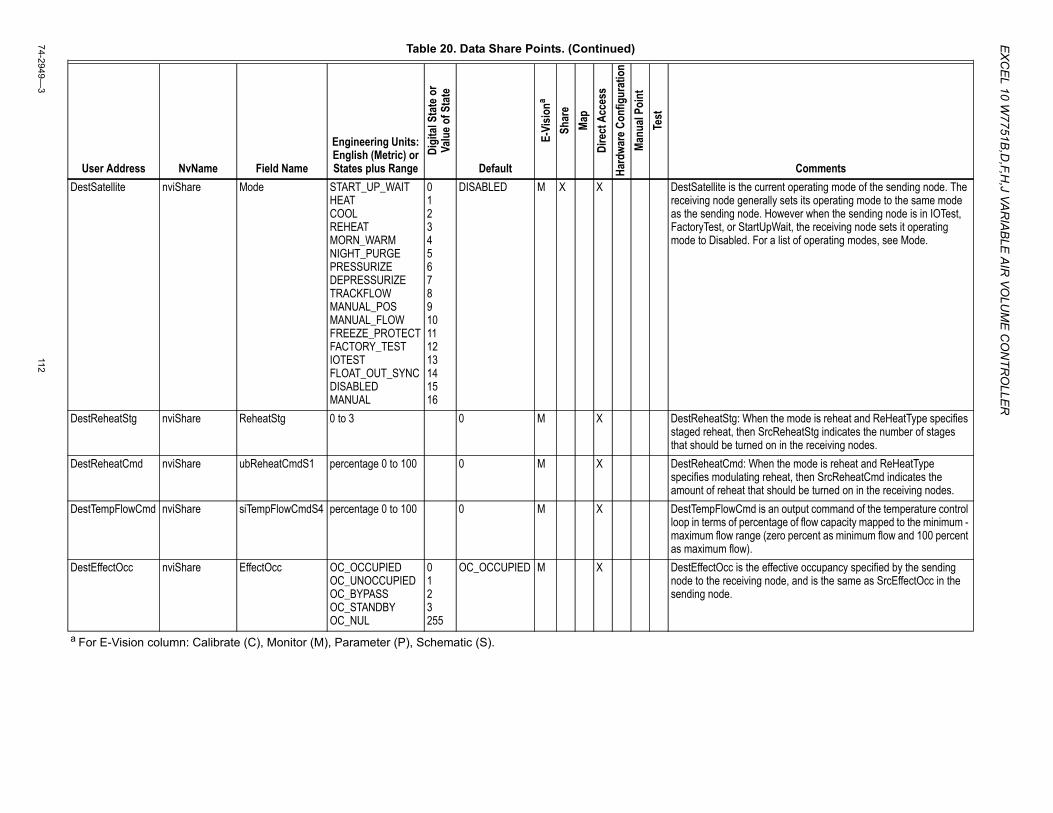
EX
CE
L 10 W7751B
,D,F,H
,J VAR
IAB
LE A
IR VO
LUM
E C
ON
TRO
LLER
74-2949—3
112
DestSatellite nviShare Mode START_UP_WAITHEATCOOLREHEATMORN_WARMNIGHT_PURGEPRESSURIZEDEPRESSURIZETRACKFLOWMANUAL_POSMANUAL_FLOWFREEZE_PROTECTFACTORY_TESTIOTESTFLOAT_OUT_SYNCDISABLEDMANUAL
012345678910111213141516
DISABLED M X X DestSatellite is the current operating mode of the sending node. The receiving node generally sets its operating mode to the same mode as the sending node. However when the sending node is in IOTest, FactoryTest, or StartUpWait, the receiving node sets it operating mode to Disabled. For a list of operating modes, see Mode.
DestReheatStg nviShare ReheatStg 0 to 3 0 M X DestReheatStg: When the mode is reheat and ReHeatType specifies staged reheat, then SrcReheatStg indicates the number of stages that should be turned on in the receiving nodes.
DestReheatCmd nviShare ubReheatCmdS1 percentage 0 to 100 0 M X DestReheatCmd: When the mode is reheat and ReHeatType specifies modulating reheat, then SrcReheatCmd indicates the amount of reheat that should be turned on in the receiving nodes.
DestTempFlowCmd nviShare siTempFlowCmdS4 percentage 0 to 100 0 M X DestTempFlowCmd is an output command of the temperature control loop in terms of percentage of flow capacity mapped to the minimum - maximum flow range (zero percent as minimum flow and 100 percent as maximum flow).
DestEffectOcc nviShare EffectOcc OC_OCCUPIEDOC_UNOCCUPIEDOC_BYPASSOC_STANDBYOC_NUL
0123255
OC_OCCUPIED M X DestEffectOcc is the effective occupancy specified by the sending node to the receiving node, and is the same as SrcEffectOcc in the sending node.
Table 20. Data Share Points. (Continued)
User Address NvName Field Name
Engineering Units: English (Metric) or States plus Range
Digi
tal S
tate
or
Valu
e of S
tate
Default
E-Vi
siona
Shar
eMa
pDi
rect
Acc
ess
Hard
ware
Con
figur
atio
nMa
nual
Poin
tTe
st
Comments
a For E-Vision column: Calibrate (C), Monitor (M), Parameter (P), Schematic (S).
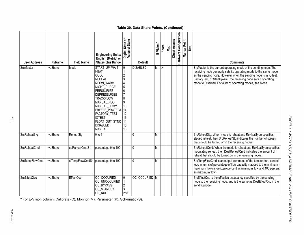
EX
CEL 10 W
7751B,D
,F,H,J VA
RIA
BLE
AIR
VOLU
ME
CO
NTR
OLLE
R
11374-2949—
3
SrcMaster nvoShare Mode START_UP_WAITHEATCOOLREHEATMORN_WARMNIGHT_PURGEPRESSURIZEDEPRESSURIZETRACKFLOWMANUAL_POSMANUAL_FLOWFREEZE_PROTECTFACTORY_TESTIOTESTFLOAT_OUT_SYNCDISABLEDMANUAL
012345678910111213141516
DISABLED M X SrcMaster is the current operating mode of the sending node. The receiving node generally sets its operating mode to the same mode as the sending node. However when the sending node is in IOTest, FactoryTest, or StartUpWait, the receiving node sets it operating mode to Disabled. For a list of operating modes, see Mode.
SrcReheatStg nvoShare ReheatStg 0 to 3 0 M SrcReheatStg: When mode is reheat and ReHeatType specifies staged reheat, then SrcReheatStg indicates the number of stages that should be turned on in the receiving nodes.
SrcReheatCmd nvoShare ubReheatCmdS1 percentage 0 to 100 0 M SrcReheatCmd: When the mode is reheat and ReHeatType specifies modulating reheat, then DestReheatCmd indicates the amount of reheat that should be turned on in the receiving nodes.
SrcTempFlowCmd nvoShare siTempFlowCmdS4 percentage 0 to 100 0 M SrcTempFlowCmd is an output command of the temperature control loop in terms of percentage of flow capacity mapped to the minimum - maximum flow range (zero percent as minimum flow and 100 percent as maximum flow).
SrcEffectOcc nvoShare EffectOcc OC_OCCUPIED OC_UNOCCUPIEDOC_BYPASSOC_STANDBYOC_NUL
0123255
OC_OCCUPIED M SrcEffectOcc is the effective occupancy specified by the sending node to the receiving node, and is the same as DestEffectOcc in the sending node.
Table 20. Data Share Points. (Continued)
User Address NvName Field Name
Engineering Units: English (Metric) or States plus Range
Digi
tal S
tate
or
Valu
e of S
tate
Default
E-Vi
siona
Shar
eMa
pDi
rect
Acc
ess
Hard
ware
Con
figur
atio
nMa
nual
Poin
tTe
st
Comments
a For E-Vision column: Calibrate (C), Monitor (M), Parameter (P), Schematic (S).
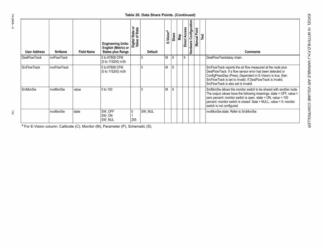
EX
CE
L 10 W7751B
,D,F,H
,J VAR
IAB
LE A
IR VO
LUM
E C
ON
TRO
LLER
74-2949—3
114
DestFlowTrack nviFlowTrack 0 to 67808 CFM (0 to 115200) m3h
0 M X X DestFlowTrackdaisy chain.
SrcFlowTrack nvoFlowTrack 0 to 67808 CFM (0 to 115200) m3h
0 M X SrcFlowTrack reports the air flow measured at the node plus DestFlowTrack. If a flow sensor error has been detected or ConfigPressDep (Press_Dependent in E-Vision) is true, then SrcFlowTrack is set to Invalid. If DestFlowTrack is Invalid, SrcFlowTrack is also set to Invalid.
SrcMonSw nvoMonSw value 0 to 100 0 M X SrcMonSw allows the monitor switch to be shared with another node. The output values have the following meanings: state = OFF, value = zero percent: monitor switch is open. state = ON, value = 100 percent: monitor switch is closed. Sate = NULL, value = 0: monitor switch is not configured.
nvoMonSw state SW_OFFSW_ONSW_NUL
01255
SW_NUL nvoMonSw.state: Refer to SrcMonSw.
Table 20. Data Share Points. (Continued)
User Address NvName Field Name
Engineering Units: English (Metric) or States plus Range
Digi
tal S
tate
or
Valu
e of S
tate
Default
E-Vi
siona
Shar
eMa
pDi
rect
Acc
ess
Hard
ware
Con
figur
atio
nMa
nual
Poin
tTe
st
Comments
a For E-Vision column: Calibrate (C), Monitor (M), Parameter (P), Schematic (S).
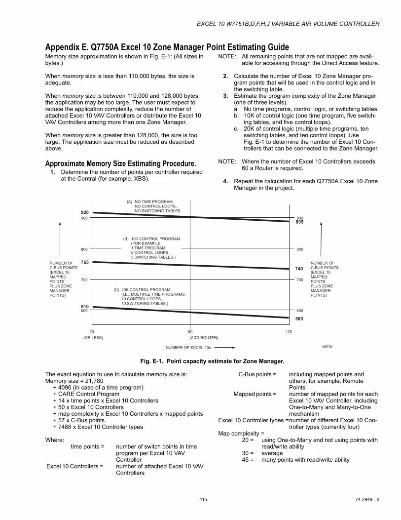
EXCEL 10 W7751B,D,F,H,J VARIABLE AIR VOLUME CONTROLLER
115 74-2949—3
Appendix E. Q7750A Excel 10 Zone Manager Point Estimating GuideMemory size approximation is shown in Fig. E-1: (All sizes in bytes.)
When memory size is less than 110,000 bytes, the size is adequate.
When memory size is between 110,000 and 128,000 bytes, the application may be too large. The user must expect to reduce the application complexity, reduce the number of attached Excel 10 VAV Controllers or distribute the Excel 10 VAV Controllers among more than one Zone Manager.
When memory size is greater than 128,000, the size is too large. The application size must be reduced as described above.
Approximate Memory Size Estimating Procedure.1. Determine the number of points per controller required
at the Central (for example, XBS).
NOTE: All remaining points that are not mapped are avail-able for accessing through the Direct Access feature.
2. Calculate the number of Excel 10 Zone Manager pro-gram points that will be used in the control logic and in the switching table.
3. Estimate the program complexity of the Zone Manager (one of three levels).a. No time programs, control logic, or switching tables.b. 10K of control logic (one time program, five switch-
ing tables, and five control loops).c. 20K of control logic (multiple time programs, ten
switching tables, and ten control loops). Use Fig. E-1 to determine the number of Excel 10 Con-trollers that can be connected to the Zone Manager.
NOTE: Where the number of Excel 10 Controllers exceeds 60 a Router is required.
4. Repeat the calculation for each Q7750A Excel 10 Zone Manager in the project.
Fig. E-1. Point capacity estimate for Zone Manager.
The exact equation to use to calculate memory size is:Memory size = 21,780
+ 4096 (in case of a time program)+ CARE Control Program+ 14 x time points x Excel 10 Controllers+ 50 x Excel 10 Controllers+ map complexity x Excel 10 Controllers x mapped points+ 57 x C-Bus points+ 7488 x Excel 10 Controller types
Where:time points = number of switch points in time
program per Excel 10 VAV Controller
Excel 10 Controllers = number of attached Excel 10 VAV Controllers
C-Bus points = including mapped points and others; for example, Remote Points
Mapped points = number of mapped points for each Excel 10 VAV Controller, including One-to-Many and Many-to-One mechanism
Excel 10 Controller types =number of different Excel 10 Con-troller types (currently four)
Map complexity =20 = using One-to-Many and not using points with
read/write ability30 = average45 = many points with read/write ability
20 60 120
600
700
800
900
600
700
800
900
920
765
610
585
740
895
NUMBER OFC-BUS POINTS(EXCEL 10MAPPED POINTSPLUS ZONEMANAGERPOINTS)
(OR LESS) (ADD ROUTER)
NUMBER OF EXCEL 10s
(C)
(A)
NUMBER OFC-BUS POINTS(EXCEL 10MAPPED POINTSPLUS ZONEMANAGERPOINTS)
NO TIME PROGRAM,NO CONTROL LOOPS, NO SWITCHING TABLES.
20K CONTROL PROGRAM(I.E., MULTIPLE TIME PROGRAMS,10 CONTROL LOOPS, 10 SWITCHING TABLES.)
10K CONTROL PROGRAM(FOR EXAMPLE, 1 TIME PROGRAM,5 CONTROL LOOPS, 5 SWITCHING TABLES.)
(B)
M8729
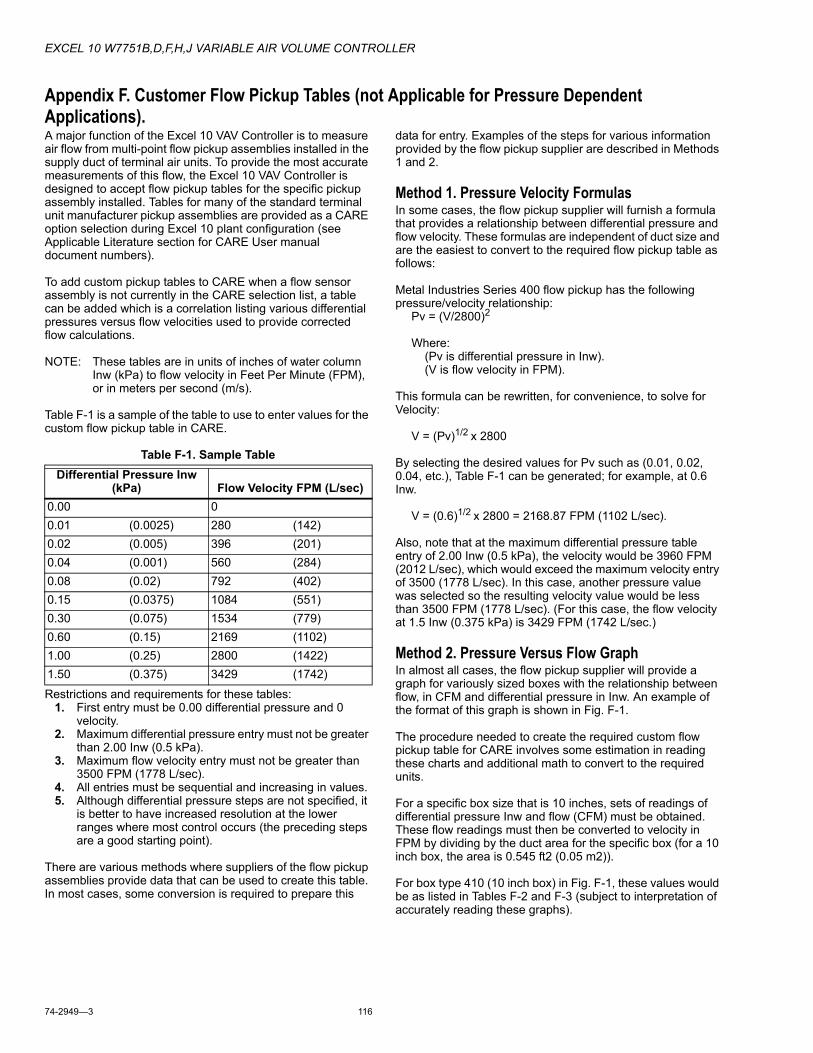
EXCEL 10 W7751B,D,F,H,J VARIABLE AIR VOLUME CONTROLLER
74-2949—3 116
Appendix F. Customer Flow Pickup Tables (not Applicable for Pressure Dependent Applications).A major function of the Excel 10 VAV Controller is to measure air flow from multi-point flow pickup assemblies installed in the supply duct of terminal air units. To provide the most accurate measurements of this flow, the Excel 10 VAV Controller is designed to accept flow pickup tables for the specific pickup assembly installed. Tables for many of the standard terminal unit manufacturer pickup assemblies are provided as a CARE option selection during Excel 10 plant configuration (see Applicable Literature section for CARE User manual document numbers).
To add custom pickup tables to CARE when a flow sensor assembly is not currently in the CARE selection list, a table can be added which is a correlation listing various differential pressures versus flow velocities used to provide corrected flow calculations.
NOTE: These tables are in units of inches of water column Inw (kPa) to flow velocity in Feet Per Minute (FPM), or in meters per second (m/s).
Table F-1 is a sample of the table to use to enter values for the custom flow pickup table in CARE.
Table F-1. Sample Table
Restrictions and requirements for these tables:1. First entry must be 0.00 differential pressure and 0
velocity.2. Maximum differential pressure entry must not be greater
than 2.00 Inw (0.5 kPa).3. Maximum flow velocity entry must not be greater than
3500 FPM (1778 L/sec).4. All entries must be sequential and increasing in values.5. Although differential pressure steps are not specified, it
is better to have increased resolution at the lower ranges where most control occurs (the preceding steps are a good starting point).
There are various methods where suppliers of the flow pickup assemblies provide data that can be used to create this table. In most cases, some conversion is required to prepare this
data for entry. Examples of the steps for various information provided by the flow pickup supplier are described in Methods 1 and 2.
Method 1. Pressure Velocity FormulasIn some cases, the flow pickup supplier will furnish a formula that provides a relationship between differential pressure and flow velocity. These formulas are independent of duct size and are the easiest to convert to the required flow pickup table as follows:
Metal Industries Series 400 flow pickup has the following pressure/velocity relationship:
Pv = (V/2800)2
Where: (Pv is differential pressure in Inw). (V is flow velocity in FPM).
This formula can be rewritten, for convenience, to solve for Velocity:
V = (Pv)1/2 x 2800
By selecting the desired values for Pv such as (0.01, 0.02, 0.04, etc.), Table F-1 can be generated; for example, at 0.6 Inw.
V = (0.6)1/2 x 2800 = 2168.87 FPM (1102 L/sec).
Also, note that at the maximum differential pressure table entry of 2.00 Inw (0.5 kPa), the velocity would be 3960 FPM (2012 L/sec), which would exceed the maximum velocity entry of 3500 (1778 L/sec). In this case, another pressure value was selected so the resulting velocity value would be less than 3500 FPM (1778 L/sec). (For this case, the flow velocity at 1.5 Inw (0.375 kPa) is 3429 FPM (1742 L/sec.)
Method 2. Pressure Versus Flow GraphIn almost all cases, the flow pickup supplier will provide a graph for variously sized boxes with the relationship between flow, in CFM and differential pressure in Inw. An example of the format of this graph is shown in Fig. F-1.
The procedure needed to create the required custom flow pickup table for CARE involves some estimation in reading these charts and additional math to convert to the required units.
For a specific box size that is 10 inches, sets of readings of differential pressure Inw and flow (CFM) must be obtained. These flow readings must then be converted to velocity in FPM by dividing by the duct area for the specific box (for a 10 inch box, the area is 0.545 ft2 (0.05 m2)).
For box type 410 (10 inch box) in Fig. F-1, these values would be as listed in Tables F-2 and F-3 (subject to interpretation of accurately reading these graphs).
Differential Pressure Inw (kPa) Flow Velocity FPM (L/sec)
0.00 0 0.01 (0.0025) 280 (142) 0.02 (0.005) 396 (201) 0.04 (0.001) 560 (284) 0.08 (0.02) 792 (402) 0.15 (0.0375) 1084 (551) 0.30 (0.075) 1534 (779) 0.60 (0.15) 2169 (1102) 1.00 (0.25) 2800 (1422) 1.50 (0.375) 3429 (1742)
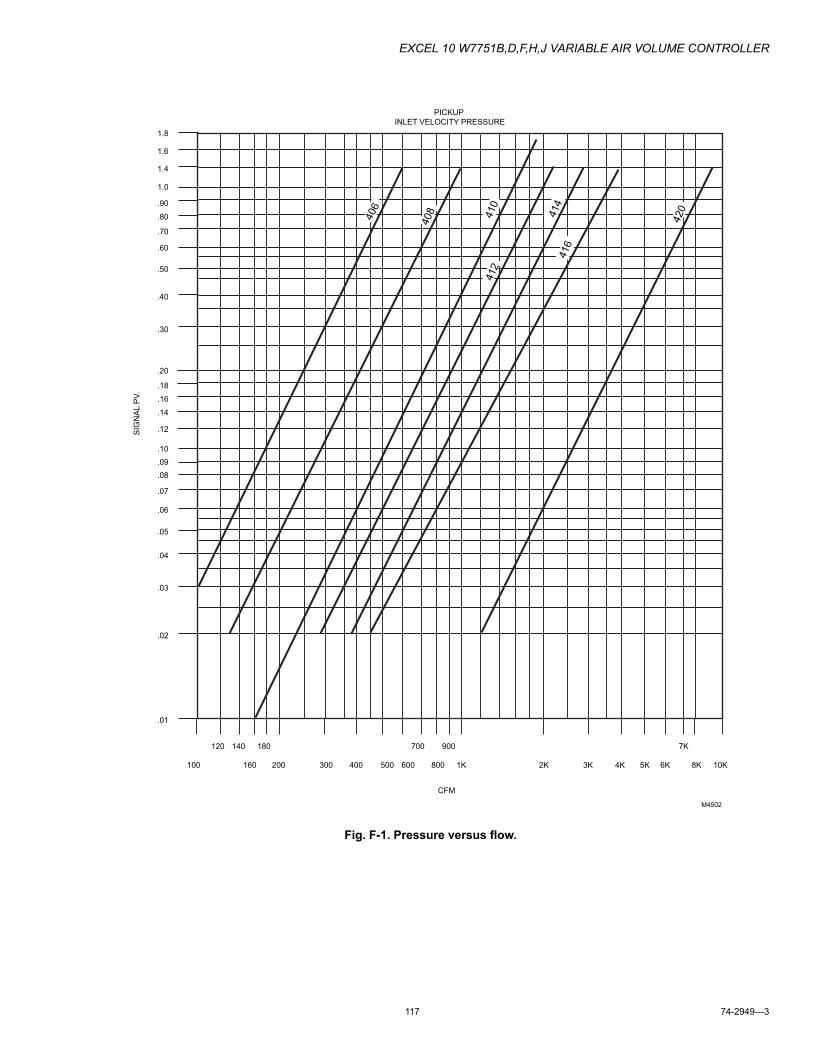
EXCEL 10 W7751B,D,F,H,J VARIABLE AIR VOLUME CONTROLLER
117 74-2949—3
Fig. F-1. Pressure versus flow.
1.8
PICKUP
INLET VELOCITY PRESSURE
406
408
410
412
414
416
100 200 300 400 500 600
700
800
900
1K 2K 3K 4K 5K 6K
7K
8K 10K
.01
.02
.03
.04
.05
.06
.07
.80
.90
.30
.40
.50
.60
.70
.08
.09
1.0
1.4
1.6
.10
.12
.14
.16
.18
.20
120 140
160
180
CFM
SIG
NA
L P
V.
M4502
420
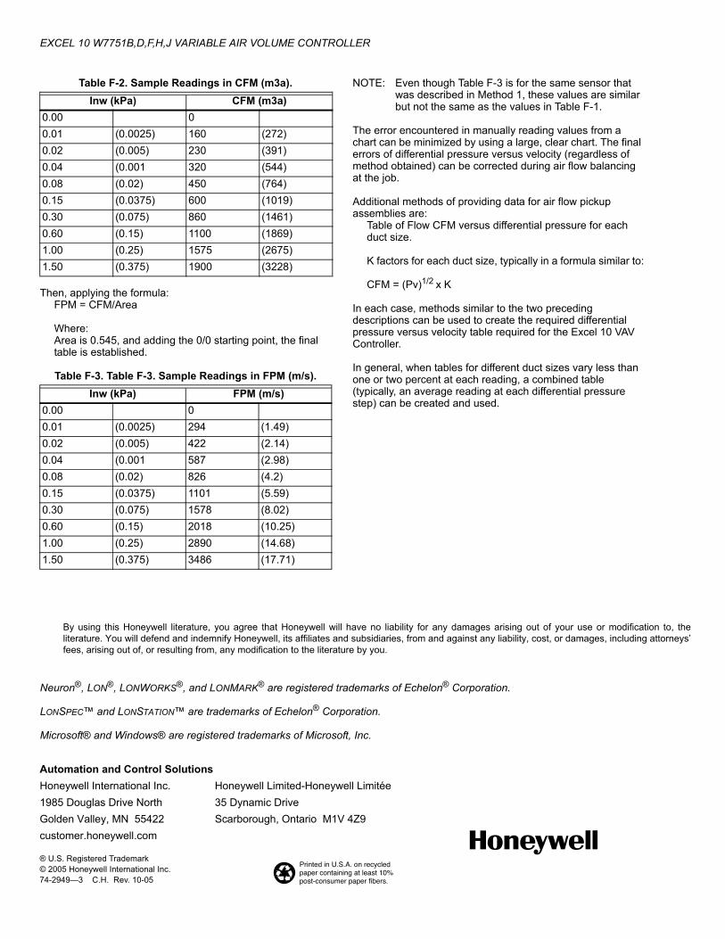
EXCEL 10 W7751B,D,F,H,J VARIABLE AIR VOLUME CONTROLLER
Automation and Control SolutionsHoneywell International Inc. Honeywell Limited-Honeywell Limitée1985 Douglas Drive North 35 Dynamic DriveGolden Valley, MN 55422 Scarborough, Ontario M1V 4Z9customer.honeywell.com
® U.S. Registered Trademark© 2005 Honeywell International Inc.74-2949—3 C.H. Rev. 10-05
Table F-2. Sample Readings in CFM (m3a).
Then, applying the formula:FPM = CFM/Area
Where:Area is 0.545, and adding the 0/0 starting point, the final table is established.
Table F-3. Table F-3. Sample Readings in FPM (m/s).
NOTE: Even though Table F-3 is for the same sensor that was described in Method 1, these values are similar but not the same as the values in Table F-1.
The error encountered in manually reading values from a chart can be minimized by using a large, clear chart. The final errors of differential pressure versus velocity (regardless of method obtained) can be corrected during air flow balancing at the job.
Additional methods of providing data for air flow pickup assemblies are:
Table of Flow CFM versus differential pressure for each duct size.
K factors for each duct size, typically in a formula similar to:
CFM = (Pv)1/2 x K
In each case, methods similar to the two preceding descriptions can be used to create the required differential pressure versus velocity table required for the Excel 10 VAV Controller.
In general, when tables for different duct sizes vary less than one or two percent at each reading, a combined table (typically, an average reading at each differential pressure step) can be created and used.
Neuron®, LON®, LONWORKS®, and LONMARK® are registered trademarks of Echelon® Corporation.
LONSPEC™ and LONSTATION™ are trademarks of Echelon® Corporation.
Microsoft® and Windows® are registered trademarks of Microsoft, Inc.
Inw (kPa) CFM (m3a)0.00 00.01 (0.0025) 160 (272)0.02 (0.005) 230 (391)0.04 (0.001 320 (544)0.08 (0.02) 450 (764)0.15 (0.0375) 600 (1019)0.30 (0.075) 860 (1461)0.60 (0.15) 1100 (1869)1.00 (0.25) 1575 (2675)1.50 (0.375) 1900 (3228)
Inw (kPa) FPM (m/s)0.00 00.01 (0.0025) 294 (1.49)0.02 (0.005) 422 (2.14)0.04 (0.001 587 (2.98)0.08 (0.02) 826 (4.2)0.15 (0.0375) 1101 (5.59)0.30 (0.075) 1578 (8.02)0.60 (0.15) 2018 (10.25)1.00 (0.25) 2890 (14.68)1.50 (0.375) 3486 (17.71)
By using this Honeywell literature, you agree that Honeywell will have no liability for any damages arising out of your use or modification to, the literature. You will defend and indemnify Honeywell, its affiliates and subsidiaries, from and against any liability, cost, or damages, including attorneys’ fees, arising out of, or resulting from, any modification to the literature by you.