Embed Size (px)
Citation preview
TM
Effective: October 2012
F-74-800
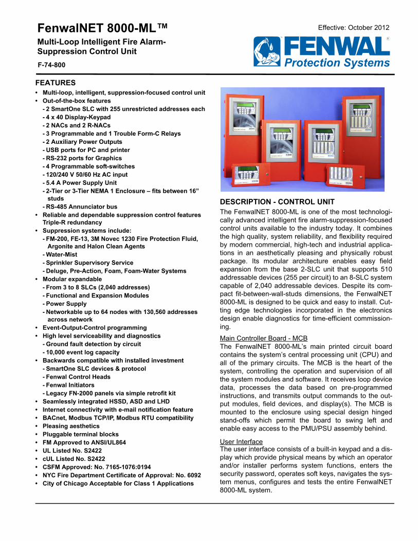
FenwalNET 8000-ML™ Multi-Loop Intelligent Fire Alarm-Suppression Control Unit
DESCRIPTION - CONTROL UNITThe FenwalNET 8000-ML is one of the most technologi-cally advanced intelligent fire alarm-suppression-focusedcontrol units available to the industry today. It combinesthe high quality, system reliability, and flexibility requiredby modern commercial, high-tech and industrial applica-tions in an aesthetically pleasing and physically robustpackage. Its modular architecture enables easy fieldexpansion from the base 2-SLC unit that supports 510addressable devices (255 per circuit) to an 8-SLC systemcapable of 2,040 addressable devices. Despite its com-pact fit-between-wall-studs dimensions, the FenwalNET8000-ML is designed to be quick and easy to install. Cut-ting edge technologies incorporated in the electronicsdesign enable diagnostics for time-efficient commission-ing.
Main Controller Board - MCBThe FenwalNET 8000-ML’s main printed circuit boardcontains the system’s central processing unit (CPU) andall of the primary circuits. The MCB is the heart of thesystem, controlling the operation and supervision of allthe system modules and software. It receives loop devicedata, processes the data based on pre-programmedinstructions, and transmits output commands to the out-put modules, field devices, and display(s). The MCB ismounted to the enclosure using special design hingedstand-offs which permit the board to swing left andenable easy access to the PMU/PSU assembly behind.
User InterfaceThe user interface consists of a built-in keypad and a dis-play which provide physical means by which an operatorand/or installer performs system functions, enters thesecurity password, operates soft keys, navigates the sys-tem menus, configures and tests the entire FenwalNET8000-ML system.
FEATURES• Multi-loop, intelligent, suppression-focused control unit• Out-of-the-box features
- 2 SmartOne SLC with 255 unrestricted addresses each- 4 x 40 Display-Keypad- 2 NACs and 2 R-NACs- 3 Programmable and 1 Trouble Form-C Relays- 2 Auxiliary Power Outputs - USB ports for PC and printer- RS-232 ports for Graphics- 4 Programmable soft-switches- 120/240 V 50/60 Hz AC input - 5.4 A Power Supply Unit- 2-Tier or 3-Tier NEMA 1 Enclosure – fits between 16”
studs- RS-485 Annunciator bus
• Reliable and dependable suppression control features Triple-R redundancy
• Suppression systems include:- FM-200, FE-13, 3M Novec 1230 Fire Protection Fluid,
Argonite and Halon Clean Agents- Water-Mist- Sprinkler Supervisory Service- Deluge, Pre-Action, Foam, Foam-Water Systems
• Modular expandable- From 3 to 8 SLCs (2,040 addresses)- Functional and Expansion Modules- Power Supply- Networkable up to 64 nodes with 130,560 addresses
across network • Event-Output-Control programming• High level serviceability and diagnostics
- Ground fault detection by circuit - 10,000 event log capacity
• Backwards compatible with installed investment- SmartOne SLC devices & protocol- Fenwal Control Heads - Fenwal Initiators- Legacy FN-2000 panels via simple retrofit kit
• Seamlessly integrated HSSD, ASD and LHD• Internet connectivity with e-mail notification feature• BACnet, Modbus TCP/IP, Modbus RTU compatibility• Pleasing aesthetics• Pluggable terminal blocks• FM Approved to ANSI/UL864• UL Listed No. S2422• cUL Listed No. S2422• CSFM Approved: No. 7165-1076:0194• NYC Fire Department Certificate of Approval: No. 6092• City of Chicago Acceptable for Class 1 Applications
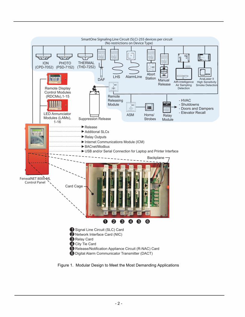
Figure 1. Modular Design to Meet the Most Demanding Applications
Suppression Release
MO
DE
LA
I,N
/O
INST
RUC
TIO
NSSE
EIN
STAL
LATI
ON
CAT
.NO
.70-
4070
08-0
01
Smar
tOne
TM
FOR
SER
VICE
SEN
DTO
:KI
DD
E-FE
NWAL
,IN
C.
400
MAI
NST
.AS
HLA
ND,
MA
0172
1D
ATE
OF
MAN
UFA
CTU
RE:
MAX
.IN
STAL
L.TE
MP.
120°
F
7 6 5 4 3 2 1
06-2
3557
8-00
1
PCPCPCPC(+)(-)(+)(-)
8A
SWB
SW(+)LED
(-)LED
ALL
TERM
INAL
SAR
EPO
WER
LIM
ITE
D
ManualRelease
RemoteReleasingModule
ION(CPD-7052)
PHOTO(PSD-7152)
THERMAL(THD-7252)
SmartOne Signaling Line Circuit (SLC)-255 devices per circuit(No restrictions on Device Type)
FenwalNET 8000-MLControl Panel
ADDRESSABLE RELEASEMODULE
Release
AGENT
RELEASE
ASM Horns/Strobes
Additional SLCs
MO
DEL
AO
INS
TRU
CTI
ON
SS
EE
INS
TALL
ATIO
NC
AT. N
O. 7
0-40
8004
-001
Smar
tOne
TM
FOR
SER
VIC
E S
EN
DTO
:K
IDD
E-F
EN
WA
L, IN
C.
400
MA
IN S
T.A
SH
LAN
D, M
A01
721
DAT
E O
F M
AN
UF A
CTU
RE
:
MA
X. I
NS
TALL
.TE
MP.
120
°F
7 6 5 4 3 2 1
06-2
3557
7-00
1
PCPCPCPC(+)(-)(+)(-)N/CCOMN/O
TER
MIN
ALS
5-7
AR
E P
OW
ER
LIM
ITE
DTE
RM
INA
LS 1
-4A
RE
PO
WE
R L
IMIT
ED
RelayModule
- HVAC- Shutdowns- Doors and Dampers- Elevator Recall
Relay Outputs
Remote DisplayControl Modules(RDCMs),1-15
LED AnnunciatorModules (LAMs),
1-16
SmartOneAPIC
MO
DE
LA
I,N
/O
INST
RUC
TIO
NSSE
EIN
STAL
LATI
ON
CAT
.NO
.70-
4070
08-0
01
Smar
tOne
TM
FOR
SER
VICE
SEN
DTO
:KI
DD
E-FE
NWAL
,IN
C.
400
MAI
NST
.AS
HLA
ND,
MA
0172
1D
ATE
OF
MAN
UFA
CTU
RE:
MAX
.IN
STAL
L.TE
MP.
120°
F
7 6 5 4 3 2 1
06-2
3557
8-00
1
PCPCPCPC(+)(-)(+)(-)
8A
SWB
SW(+)LED
(-)LED
ALL
TERM
INAL
SAR
EPO
WER
LIM
ITE
D
PUSH
PULL
Internet Communications Module (ICM)BACnet/Modbus
MO
DE
LA
I,N
/O
INST
RUC
TIO
NSSE
EIN
STAL
LATI
ON
CAT
.NO
.70-
4070
08-0
01
Smar
tOne
TM
FOR
SER
VICE
SEN
DTO
:KI
DD
E-FE
NWAL
,IN
C.
400
MAI
NST
.AS
HLA
ND,
MA
0172
1D
ATE
OF
MAN
UFA
CTU
RE:
MAX
.IN
STAL
L.TE
MP.
120°
F
7 6 5 4 3 2 1
06-2
3557
8-00
1
PCPCPCPC(+)(-)(+)(-)
8A
SWB
SW(+)LED
(-)LED
ALL
TERM
INAL
SAR
EPO
WER
LIM
ITE
D
DAFLHS
SUPPRES SION SYSTEM ABOR T
AbortStation
AlarmLin e
SmartOne
AlarmLine
KIDDE-FEN WA L, INC.400 MAIN ST . A SHLAND, MA 01721
ANALASER II INTERF ACE MODULEPA RT . NO. 89-300010-001
FENW ALNET ADDRESSTMFM
APPROVED
IN
OU TRXTX
RXTX
GN D
ALL TERMINALS ARE POWER LIMITED
R
AIR-IntelligenceAir Sampling
Detection
AnaLaser IIHigh Sensitivity
Smoke Detection
Card Cage
Backplane
Signal Line Circuit (SLC) CardNetwork Interface Card (NIC)Relay CardCity Tie CardRelease/Notification Appliance Circuit (R-NAC) CardDigital Alarm Communicator Transmitter (DACT)
1 2 3 4 5 6
123456
USB and/or Serial Connection for Laptop and Printer Interface
- 2 -
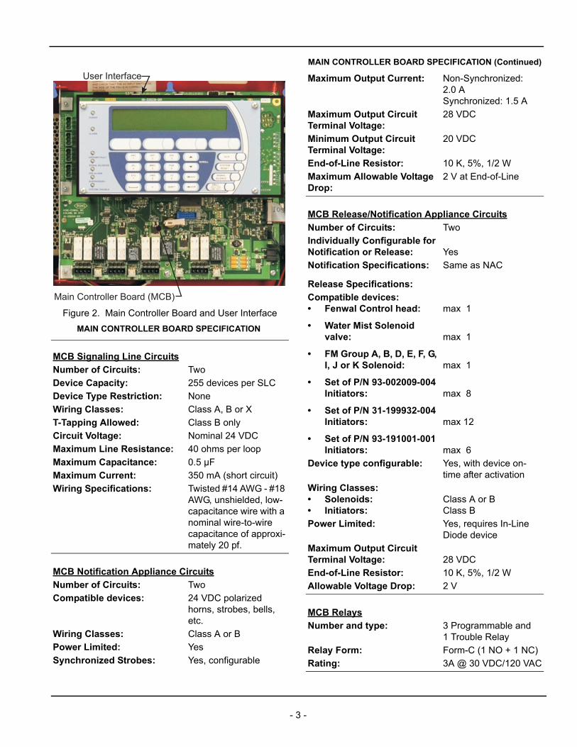
Figure 2. Main Controller Board and User Interface
MAIN CONTROLLER BOARD SPECIFICATION
MCB Signaling Line Circuits
Number of Circuits: Two
Device Capacity: 255 devices per SLC
Device Type Restriction: None
Wiring Classes: Class A, B or X
T-Tapping Allowed: Class B only
Circuit Voltage: Nominal 24 VDC
Maximum Line Resistance: 40 ohms per loop
Maximum Capacitance: 0.5 µF
Maximum Current: 350 mA (short circuit)
Wiring Specifications: Twisted #14 AWG - #18 AWG, unshielded, low-capacitance wire with a nominal wire-to-wire capacitance of approxi-mately 20 pf.
MCB Notification Appliance Circuits
Number of Circuits: Two
Compatible devices: 24 VDC polarized horns, strobes, bells, etc.
Wiring Classes: Class A or B
Power Limited: Yes
Synchronized Strobes: Yes, configurable
Main Controller Board (MCB)
User Interface Maximum Output Current: Non-Synchronized: 2.0 ASynchronized: 1.5 A
Maximum Output CircuitTerminal Voltage:
28 VDC
Minimum Output CircuitTerminal Voltage:
20 VDC
End-of-Line Resistor: 10 K, 5%, 1/2 W
Maximum Allowable Voltage Drop:
2 V at End-of-Line
MCB Release/Notification Appliance Circuits
Number of Circuits: Two
Individually Configurable for Notification or Release: Yes
Notification Specifications: Same as NAC
Release Specifications:
Compatible devices:• Fenwal Control head:
• Water Mist Solenoid valve:
• FM Group A, B, D, E, F, G, I, J or K Solenoid:
• Set of P/N 93-002009-004 Initiators:
• Set of P/N 31-199932-004 Initiators:
• Set of P/N 93-191001-001 Initiators:
max 1
max 1
max 1
max 8
max 12
max 6
Device type configurable: Yes, with device on-time after activation
Wiring Classes:• Solenoids:• Initiators:
Class A or BClass B
Power Limited: Yes, requires In-Line Diode device
Maximum Output CircuitTerminal Voltage: 28 VDC
End-of-Line Resistor: 10 K, 5%, 1/2 W
Allowable Voltage Drop: 2 V
MCB Relays
Number and type: 3 Programmable and1 Trouble Relay
Relay Form: Form-C (1 NO + 1 NC)
Rating: 3A @ 30 VDC/120 VAC
MAIN CONTROLLER BOARD SPECIFICATION (Continued)
- 3 -
Power SupplyThe FenwalNET 8000-ML Control Unit requires a mini-mum of one Power Supply Unit and one Power Manage-ment Unit (PMU) Board for operation. Additional PowerSupply Units may be added, based on calculated powerrequirement (refer to Battery Calculations in the Fenwal-NET 8000-ML Installation, Operation, and MaintenanceManual, P/N 06-237041-001).
One PMU board is needed to control up to 2 Power Sup-ply Units. The FenwalNET 8000-ML Control Unit designoffers optional Power Supply Units and Power Manage-ment Unit (PMU) Board to expand the available power tomeet additional power requirements.
Each enclosure of the FenwalNET 8000-ML Control Unitcan provide 20 Amps of power supply capacity and thesystem can charge up to 165-AH batteries for US appli-cations and 132-AH batteries for Canadian applications.
MCB RS-232 Serial Ports
Number of Ports: 2
Specifications: Bi-Directional 9600 Baud, 8 Data Bits, 1 Stop Bit, No Parity
MCB RS-485 Annunciator Port
Number of Ports: 1
Compatible Devices:• RDCM• R-LAM• ATM-L • ATM-R
Max. 15 devicesMax. 16 devicesMax. 16 devicesMax. 16 devices
Compatible Device Maximum:
31 in any combination and in any order
Wiring Type: Twisted shielded low-capacitance fire alarm wire
Wiring Minimum Size: AWG 18
Maximum wire length: 4,000 ft. (1,219 m)
MCB USB Device Ports:
Number of Ports: 2
MAIN CONTROLLER BOARD SPECIFICATION (Continued) POWER SUPPLY & MANAGEMENT SPECIFICATION
Number of PMUs percontrol unit
Minimum: 1Maximum: 4
Number of PSUs per PMU Minimum: 1Maximum: 2
Primary AC Input Power:• 1 PSU:
• 2 PSU:
120 VAC, 50/60 Hz, 3.2 A240 VAC, 50/60 Hz, 1.6 A
120 VAC, 50/60 Hz, 6.4 A 240 VAC, 50/60 Hz, 3.2 A
Allowable Input VoltageVariation:
115 + 5% VAC230 + 4% VAC
Secondary DC Output:• 1 PSU:• 2 PSU:
5.4 A @ 27.6 VDC10.8 A @ 27.6 VDC
Voltage Selection: Slide switch on PSU
Trouble Relay Contact Rating:
1.0 A @ 30 VDC (resistive)
AC to Battery Transfer Voltage:• 120 VAC:• 220 VAC:
109 VAC200 VAC
Battery Charging CircuitVoltage:
27.0 VDC (nominal)
Maximum Battery ChargingCircuit Current:• 1 PSU:• 2 PSU:
4 A8.9 A
Allowable Battery Type: 2 x 12 VDC Sealed Lead-Acid Only
Maximum Battery Capacity: UL/FM: 165 AHULC: 132 AH
Auxiliary Outputs: 2 per PMU,power-limited
Auxiliary Output OperatingVoltage Range:
19.2 - 27.6 VDC
Auxiliary Output MaximumCurrent:
2 A @ 470 µF max.per output
- 4 -
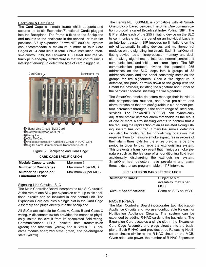
Backplane & Card CageThe Card Cage is a metal frame which supports andsecures up to six Expansion/Functional Cards pluggedinto the Backplane. The frame is fixed to the Backplaneand mounts to the enclosure in the second- or third-tierpositions. A fully expanded FenwalNET 8000-ML systemcan accommodate a maximum number of four CardCages or 24 card slots in total. Unlike installation inten-sive control units, the FenwalNET 8000-ML features vir-tually plug-and-play architecture in that the control unit isintelligent enough to detect the type of card plugged in.
Figure 3. Backplane and Card Cage
Signaling Line Circuits - SLCThe Main Controller Board incorporates two SLC circuits.At the rate of one SLC per expansion card, up to six addi-tional circuits can be included in one control unit. TheExpansion Card occupies a single slot in the Card CageAssembly and plugs directly into the backplane.
All SLC’s are suitable for Class A, Class B and Class Xwiring. A disconnect switch provides the means to physi-cally isolate the circuit from its associated field wiring.Communications LEDs indicate data transmission(green) and reception (yellow) and a Status LED indi-cates module energized state (green) and de-energizedstate (yellow).
The FenwalNET 8000-ML is compatible with all Smart-One protocol based devices. The SmartOne communica-tion protocol is called Broadcast Index Polling (BIP). TheBIP enables each of the 255 initiating device on the SLCto communicate with the panel on an individual basis inan intelligent system. BIP imposes no limitations on themix of automatic initiating devices and monitor/controlmodules on the signaling line circuit. Each SmartOne ini-tiating device has a microprocessor, memory, and deci-sion-making algorithms to interrupt normal control-unitcommunications and initiate an alarm signal. The BIPcommunication protocol divides the potential 255addresses on the SLC loops into 8 groups of 32addresses each and the panel constantly samples thegroups for fire signatures. Once a fire signature isdetected, the panel narrows down to the group with theSmartOne device(s) initiating the signature and further tothe particular address initiating the fire signature.
The SmartOne smoke detectors manage their individualdrift compensation routines, and have pre-alarm andalarm thresholds that are configurable in 0.1 percent-per-foot increments throughout the entire range of listed sen-sitivities. The FenwalNET 8000-ML can dynamicallyadjust the smoke detector alarm thresholds as the resultof one or more alarm-initiating events to confirm that afire requiring the rapid action of an associated extinguish-ing system has occurred. SmartOne smoke detectorscan also be configured for non-latching operation thatrequires them to measure smoke signatures in excess oftheir alarm thresholds for the entire pre-discharge timeperiod in order to discharge the extinguishing system.This prevents a transitory event that mimics a smoke sig-nature such as the leakage of air-conditioning fluid fromaccidentally discharging the extinguishing system.SmartOne heat detectors have pre-alarm and alarmthresholds that are programmable in 1°F intervals.
NACs & R-NACsThe Main Controller Board incorporates two NotificationAppliance Circuits and two user-configurable Releasing/Notification Appliance Circuits. The system can beexpanded by adding R-NAC cards to the backplane. TheExpansion Card occupies a single slot in the ExpansionCard Cage Assembly and plugs directly into the back-plane. Each R-NAC card provides three Releasing-Notifi-cation circuits similar to the R-NAC circuit on the MCB.Given adequate power, the number of R-NAC Expansion
CARD CAGE SPECIFICATION
Module Capacity each: Maximum 6
Number of Card Cages: Maximum 4 per MCB
Number of Expansion/Functional cards:
Maximum 24 per MCB
Card Cage Backplane
Signal Line Circuit (SLC) CardNetwork Interface Card (NIC)Relay CardCity Tie CardRelease/Notification Appliance Circuit (R-NAC) CardDigital Alarm Communicator Transmitter (DACT)
1 2 3 4 5 6
123456
SLC EXPANSION CARD SPECIFICATION
Number of Cards: Subject to slot availabilty, max 6 per MCB
Circuit Specifications: Same as SLC on MCB
- 5 -
Cards in a system is limited only by the availability of cardslots – which itself is limited to 24.
Notification Appliance Circuits can be wired as Class A orClass B and support 24 VDC polarized appliances suchas horns, strobes and bells. Strobes can be either syn-chronized or non-synchronized.
The Releasing Circuits can be wired as Class A or ClassB and configured to activate agent control heads andsolenoid valves. Fenwal initiators can only be wiredClass B. The circuit-on time is configurable from 55microseconds, 90 seconds, 10 minutes, 15 minutes, On-To-Reset, On-Off cycling dependant on the releasedevice and suppression system. While the circuits arepower limited, utilizing this option for releasing requiresthe use of a field In-Line Release Device – separate forsolenoids and initiators. An NFPA-72 compliant discon-nect switch provides the means to physically isolate thecircuit from its associated field wiring.
Triple Redundancy ProtectionUnlike some generic fire alarm control units adopted forreleasing service, at its core the FenwalNET 8000-ML issuppression-focused. Featuring the exclusive Triple-Rredundancy safeguard wherein no single component fail-ure or combination of abnormal operating conditions,including main microprocessor failure, is allowed to resultin accidental release activation, the FenwalNET 8000-MLprovides the same high quality, dependability and maxi-mum protection against inadvertent release that havebeen the hallmark of Fenwal suppression panels fordecades. The Triple-R system requires that in order toactivate a release, the main microprocessor issue tworelease commands of opposite polarity via separate sig-naling channels and that these commands combine witha signal from the control unit's watchdog timer to confirmthe microprocessor operation. The Triple-R systemensures that electrical transients or disturbances such aspower surges that could interfere with the operation ofthe main microprocessor will not inadvertently activatethe connected suppression system. The result is a morerobust and reliable suppression control unit.
RelaysThe Main Controller Board incorporates 3 programmableForm-C Relays and 1 Form-C Trouble relay. The Expan-sion Card occupies a single slot in the Card CageAssembly and plugs directly into the backplane. The sys-
tem can be expanded by adding Relay cards to the back-plane. Each Relay card provides four programmableForm-C relays similar to those on the MCB. The numberof Relay Expansion Cards in a system is limited only bythe availability of card slots – which itself is limited to 24.
Each relay is independently-driven and can be pre-pro-grammed to change state for all states of Alarm, Troubleand Supervisory conditions. Relays are normally de-energized, unless configured for Trouble. A Trouble relayis energized upon startup and changes state for anyTrouble event, including failure of the Main ControllerBoard. R-G-Y status LEDs are provided. Contact ratingsare 3 A at 30 VDC or 120 VAC.
City Tie CardThe optional City Tie Card provides connection and oper-ation for three independently operated signaling circuitsused to connect to Municipal Tie inputs as either LocalEnergy output, Shunt-Type Master Box output orReverse Polarity output. The City Tie Card occupies asingle slot in the Card Cage Assembly and plugs directlyinto the backplane. The FenwalNET 8000-ML allows oneCity Tie Card per control unit.
NetworkingFor large areas or campus-style applications, Fenwal-NET 8000-ML control units can be networked into a pow-erful system capable of supporting 130,560 addressabledevices. The FenwalNET 8000-ML has the capability toprovide true peer-to-peer networking of up to 64 controlunits. Added functionality is provided when the RemoteDisplay-Control Module (RDCM) are connected to theindividual control panels and hence into the interconnec-tion scheme. The network is capable of performing fire-
R-NAC EXPANSION CARD SPECIFICATION
Number of Cards: Subject to slot availability, max 24 per MCB
Number of Circuits Per Card: Three
Circuit Specifications: Same as R-NAC on MCB
RELAY EXPANSION CARD SPECIFICATION
Number of Cards: Subject to slot availability, max 24 per MCB
Number of Relays Per Card: Four
Relay Specifications: Same as Relays on MCB
CITY TIE CARD SPECIFICATION
Number of Cards: Max 1 per control unit
Number of Circuits Per Card: Three
Local Energy Type: 24 VDC @ 550 mA maximum
Shunt-Type Master Box: 24 VDC @ 5 A maximum
Reverse Polarity Type: 24 VDC @ 100 mA maximum
- 6 -
alarm and/or suppression system operations on a net-work-wide basis:
– Event initiation– Protected-premises local and/or remote event
annunciation– Occupant notification via audible and visible sig-
naling appliances– Process/equipment control to activate safety pro-
cedures– Fire extinguishing system release – Off-premises transmissions to central station or
fire department
The network provides several convenient interconnectprogramming schemes wherein control panels can beconfigured individually or within created groups of controlpanels. When utilizing the grouping configuration, theinterconnection automatically provides shared alarm andtrouble responses. The programmable shared responsesare: acknowledge, silence, reset, event logging and logicstatements. Operator events can be activated into theinterconnection via the control panels or any annunciator.A location address and programmable description isused to identify the panel initiating the event.
Network Interface Card – NICThe Network Interface Card regenerates and boosts net-work communications between control units and electri-cally isolates the networked units from each other. AllFenwalNET 8000-ML units must contain a NIC to be net-worked to one another. The NIC occupies a single slot inthe Card Cage Assembly. Using the NIC, the control unitstransmit and receive messages via RS485 format over atwisted pair. An optional Fiber Optic Converter Module(FOCM), in addition to the NIC, allows connectivity via afiber optic medium. The networking structure supports amixture of fiber-optic and twisted-wire interconnectionsamong networked control units. The network structurealso supports up to 4,000 ft. long 18 AWG of copper wirebetween nodes (control units).
Fiber Optic Converter Module – FOCMA fiber-optic option is available for network applications(NIC card also required) with communication pathsgreater than 4,000 ft. or where excessive electrical noiseis present. The FOCM is a bi-directional, externally-pow-ered unit which is wall mountable in the standard Fenwal-NET 8000-ML remote enclosure. One FOCM is requiredat both interconnected FenwalNET 8000-ML control unitsfor a single communication channel.
For short transmission distances (under 1 mile), such aswithin a building or on a campus, multi-mode optical fiber(MM fiber) can be used (62.5 μm core size/125 μm clad-ding diameter). For longer transmission distances (up to12 miles), single-mode (SM fiber) can be used (8.3 μm
core size/125 μm cladding diameter). Either type of fibermay be used and both connect to the FenwalNET 8000-ML power and RS-485 data lines in the same fashion.
The FOCM is shipped standard with one converter chan-nel. For greater communication security and redundancy,a second converter channel may be added. This is mosteffective if the second channel is installed in a differentpathway from the first.
Digital Alarm Communicator Transmitter – DACTThe communication capabilities of the FenwalNET 8000-ML control unit are enhanced with an optional DACTwhich transmits system status over phone lines to aCentral Station. The DACT card includes a built-inmodem and two Loop Start Public Switched TelephoneNetwork (PSTN) connections. Status LEDs are providedto indicate data transmission (green) and reception(yellow). A FenwalNET 8000-ML system allows oneDACT Card per control unit. The DACT card operates on24 Vdc and supports SIA DC-05-1999.09 Ademco Con-tact ID and SIA DC-03-1990.01 (R2003.10) protocols.
NETWORK INTERFACE CARD (NIC) SPECIFICATION
Number of Cards: Max 1 per control unit
Number of nodes in network: Maximum 64
Wiring Classes: Class A or Class B
Operating Voltage: 24 VDC
Operating Current: 63 mA
Data Ports: EIA/TIA-485
Baud Rate: 38,400 baud
Recommended Wiring: AWG 18, twisted, shielded, pair
Maximum Recommended Length:
4,000 ft. (1,219 m)
FIBER OPTIC CONVERTER MODULE (FOCM) SPECIFICATION
Operating Voltage: 24 VDC
Operating Current: 175 mA
Data Ports: EIA/TIA-485
Max. Recommended Length for MM Fiber:
1 mile (with no more than 6.4 dB/mile cable attenuation)
Max. Recommended Length for SM Fiber:
12 miles (with no more than 1.66 dB/mile cable attenuation)
Baud Rate: 38,400 Baud
Temperature Range: 0º to 50ºC
Humidity Range: 0 to 93% RH, non-condensing
Enclosure Dimensions(H x W x D):
7-1/2 x 12-3/4 x 2-3/4 (in.)191 x 324 x 70 (mm)
- 7 -
Internet Communications Module – ICMThe Internet Communications Module (ICM) can be usedto access the FenwalNET 8000-ML System via the Inter-net to view system status and current events and todownload the history log. The ICM can be programmedto transmit up to five e-mails upon the occurrence of anyunsolicited event in the system. The e-mail messageembeds a link with the IP address of the control unit thatsent the message for instant access to the remote sys-tem. The ICM can be accessed using any standard Webbrowsing program and requires no special proprietarysoftware. The ICM also allows the FenwalNET 8000-MLControl Unit to report as a slave device via the ModbusTCP/IP Protocol to a master monitoring system for auto-mated process control.
Modbus/BACnet Interface The Modbus/BACnet Interface module provides protocoltranslation between the FenwalNET 8000-ML communi-cation protocol and the communication protocol of anexternal monitoring system such as a building automa-tion system. The Modbus/BACnet Interface module con-verts the FenwalNET 8000-ML Communications Protocolto BACnet Protocol. The unit is wall mountable in thesame FenwalNET 8000-ML standard remote enclosure.The communication flow is one-way from the FenwalNET8000-ML network to the external monitoring system. Thesingle module supports systems with up to 4 SLCs. Forsystems including more than 4 SLCs, a second (Add-On)module is required.
EnclosuresThe FenwalNET 8000-ML offers two enclosure sizes,2-Tier and 3-Tier, for both main and expansion enclo-sures. The enclosures accommodate the MCB, PMU/PSU, Expansion Card Cages and Batteries. The enclo-sures are sized to fit between standard 16”-spaced wallstuds and can accommodate a pair of 12 VDC12-AH or17-AH SLA batteries (max. 40 AH). The enclosures arepainted red, rated NEMA 1 and constructed from 16AWG cold rolled steel per ASTM A-366. All Fenwalenclosures utilize a common key. Despite its compactdimensions, the enclosure allows a minimum of 1.5 in.(38 mm) of wiring space between the wall and any wiringterminal. Multiple knockouts provide flexibility in wiringentry.
DIGITAL ALARM COMMUNICATOR TRANSMITTER (DACT) SPECIFICATION
Number of Cards: Max 1 per control unit
Operating Voltage: 24 VDC
Operating Current: 37 mA
Electrical Interface: PSTN line using a RJ45X phone jack
Supported Protocols: SIA DC-05-1999.09 Ademco Contact IDSIA DC-03-1990.01 (R2003.10)
Compatible Digital Alarm Communicator Receivers (DACRs):
Sur-Gard System I, Sur-Gard System III and Osborne Hoffman Model 2000E
INTERNET COMMUNICATIONS MODULE (ICM) SPECIFICATION
Operating Voltage: 24 VDC
Operating Current: 42 mA
Operating Environment: 32º to 120ºF(0º to 49ºC)0-90% RH, non-condensing
Data Port: RJ45
Supported Field Protocols: Ethernet - Local Area Network or Wide Area Network (LAN or WAN)
Modbus/BACnet SPECIFICATION
Electrical Connections:
• 6-pin Phoenix connector, RS232
• 3-pin Phoenix connector, RS485
• Ethernet-10/100 port
Enclosure Dimensions(H x W x D):
7-1/2 x 12-3/4 x 2-3/4 (in.)191 x 324 x 70 (mm)
Operating Voltage: 9-30VDC or 12-24VAC
Operating Current: 150 mA @ 12VDC
Operating Temperature: -40F to 187F (-40C to 85C)
Humidity: 5 - 90% RH, non-condensing
Data Ports: RS232, Ethernet
Max. RS232 Cable Length: 50 ft. (15.2 m)
Supported Baud Ratefor BACnet MS/TP:
9.6 - 76.8K baud
- 8 -
Dead Front CoversA sheet-steel dead-front cover may optionally bemounted between the door and electronics to preventunwanted access to the electronics. With the dead-frontinstalled, an operator has access only to the user inter-face. A blanking plate (included) may be removed if anintegrated LED Annunciator is present. The dead front istypical in ULC/cUL applications.
Enclosure Trim RingA sheet-steel red-enamel finished trim ring may bemounted around a semi-flush FenwalNET 8000-MLenclosure to enhance the Control Unit’s aesthetic appealafter installation.
CONTROL UNIT FEATURESSeamless Integration with Specialty DetectorsSmartOne loop protocol interface cards enable theFenwalNET 8000-ML to seamlessly integrate with spe-cialty detectors. AIR-Intelligence Air Sampling SmokeDetectors (ASD) and AnaLASER-II High SensitivitySmoke Detectors (HSSD) connect via Addressable Pro-tocol Interface Cards (APIC) and AnaLASER InterfaceModules (AIM-II) respectively and report pre-alarms and
alarms in a manner analogous to SmartOne smokedetectors. AlarmLine Integrating Linear Heat Detectorsensors (LHD) connect via AlarmLine Addressable Mod-ules (AAM) and report pre-alarms and alarms similar to aSmart-One heat detector. Fixed Temperature Linear HeatSensor cables (LHS) connect via Addressable InputModules (AI) and report point alarms.
Field Programming OptionsThe FenwalNET 8000-ML Configuration Software(FCS8000) tool is used to program the control unit foreach individual site-specific application. Programming isfor control-by-event scenarios and consists of entering aseries of conditional control statements that logically joininitiating points to control-unit-based outputs and remotecontrol modules. Each SmartOne field device can beassigned a location message of up to 40 characters viathe configuration tool. A USB Device Port is available toconnect a laptop computer for application upload.
An AutoLearn routine that creates a general alarm (one-input-activates-all outputs) application can be invokedfrom the User Interface to speed the configuration pro-cess. A more sophisticated Auto-Setup routine whichautomatically configures the control unit for a typicalwaterless fire-suppression system can also be invoked.
Automatic SLC Device TestingThe FenwalNET 8000-ML features an exclusive auto-matic SLC device testing protocol. With this cutting edgesupervisory technology, the control unit routinely checksall SLC devices in groups of 32 for operational status. If agroup fails, the control unit then interrogates at lowerlevel in that group and pin-points and reports the mal-functioning device on the User Interface within seconds.
Duplicate Address DetectionElectronic device addressing is via the Handheld Pro-grammer (HHP). The fully-digitized FenwalNET 8000-MLControl Unit protocol has the ability to monitor the SLCfor devices with duplicate addresses. Should such dupli-cation be detected, the control unit displays theseaddresses on the User Interface – thereby reducing theoverall configuration time.
Battery Life TrackingThe FenwalNET 8000-ML software includes an optionalBattery Monitoring Mode which can track battery lifetimefrom the original install date and emit an audible signalon the replacement due date.
Annunciator BusThe Main Controller Board includes an RS-485 buswhich can communicate with up to a total of 31 RemoteAnnunciators. These include up to 15 RDCM RemoteDisplay/Control Modules, up to 16 LAM LED AnnunciatorModules. This capability can be expanded to include upto 16 legacy ATM-R and ATM-L Annunciator TerminalModules.
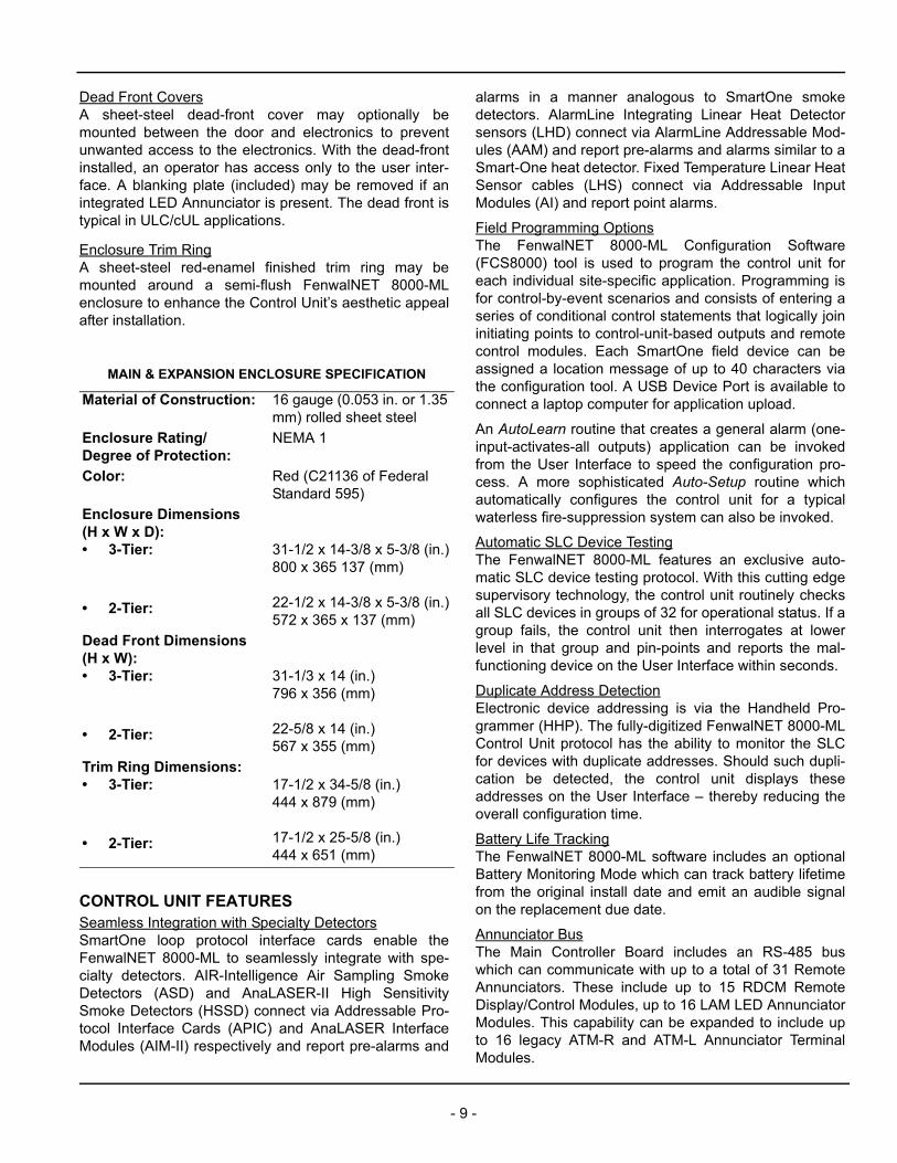
MAIN & EXPANSION ENCLOSURE SPECIFICATION
Material of Construction: 16 gauge (0.053 in. or 1.35 mm) rolled sheet steel
Enclosure Rating/Degree of Protection:
NEMA 1
Color: Red (C21136 of Federal Standard 595)
Enclosure Dimensions(H x W x D):• 3-Tier:
• 2-Tier:
31-1/2 x 14-3/8 x 5-3/8 (in.)800 x 365 137 (mm)
22-1/2 x 14-3/8 x 5-3/8 (in.)572 x 365 x 137 (mm)
Dead Front Dimensions(H x W):• 3-Tier:
• 2-Tier:
31-1/3 x 14 (in.)796 x 356 (mm)
22-5/8 x 14 (in.)567 x 355 (mm)
Trim Ring Dimensions:• 3-Tier:
• 2-Tier:
17-1/2 x 34-5/8 (in.)444 x 879 (mm)
17-1/2 x 25-5/8 (in.)444 x 651 (mm)
- 9 -
CONTROL UNIT ACCESSORIESLarge Capacity Battery CabinetAn optional NEMA-1 surface-mount Battery Cabinet isavailable for a pair of up to 12 VDC 40-AH sealed leadacid batteries. The cabinet is designed to be locatedwithin 100 feet of the control unit. The red painted cabinetis constructed of cold-rolled steel as other availableFenwalNET enclosures. The door is hinged on the leftand includes the same lock and key used with all Fenwal-NET enclosures. Three conduit knockouts are providedat the top to accommodate either ½-inch or ¾-inch stan-dard electrical conduit fittings.
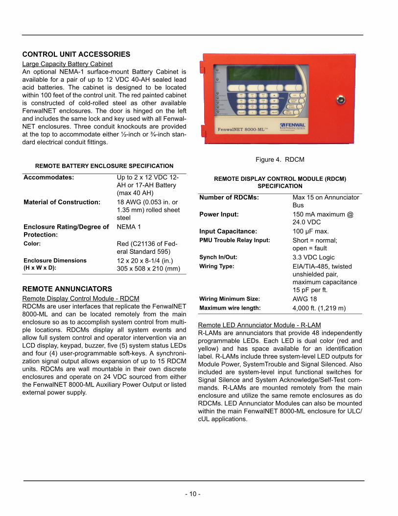
REMOTE ANNUNCIATORSRemote Display Control Module - RDCMRDCMs are user interfaces that replicate the FenwalNET8000-ML and can be located remotely from the mainenclosure so as to accomplish system control from multi-ple locations. RDCMs display all system events andallow full system control and operator intervention via anLCD display, keypad, buzzer, five (5) system status LEDsand four (4) user-programmable soft-keys. A synchroni-zation signal output allows expansion of up to 15 RDCMunits. RDCMs are wall mountable in their own discreteenclosures and operate on 24 VDC sourced from eitherthe FenwalNET 8000-ML Auxiliary Power Output or listedexternal power supply.
Figure 4. RDCM
Remote LED Annunciator Module - R-LAMR-LAMs are annunciators that provide 48 independentlyprogrammable LEDs. Each LED is dual color (red andyellow) and has space available for an identificationlabel. R-LAMs include three system-level LED outputs forModule Power, SystemTrouble and Signal Silenced. Alsoincluded are system-level input functional switches forSignal Silence and System Acknowledge/Self-Test com-mands. R-LAMs are mounted remotely from the mainenclosure and utilize the same remote enclosures as doRDCMs. LED Annunciator Modules can also be mountedwithin the main FenwalNET 8000-ML enclosure for ULC/cUL applications.
REMOTE BATTERY ENCLOSURE SPECIFICATION
Accommodates: Up to 2 x 12 VDC 12-AH or 17-AH Battery(max 40 AH)
Material of Construction: 18 AWG (0.053 in. or 1.35 mm) rolled sheet steel
Enclosure Rating/Degree of Protection:
NEMA 1
Color: Red (C21136 of Fed-eral Standard 595)
Enclosure Dimensions(H x W x D):
12 x 20 x 8-1/4 (in.)305 x 508 x 210 (mm)
REMOTE DISPLAY CONTROL MODULE (RDCM) SPECIFICATION
Number of RDCMs: Max 15 on Annunciator Bus
Power Input: 150 mA maximum @ 24.0 VDC
Input Capacitance: 100 µF max.PMU Trouble Relay Input: Short = normal;
open = faultSynch In/Out: 3.3 VDC LogicWiring Type: EIA/TIA-485, twisted
unshielded pair, maximum capacitance 15 pF per ft.
Wiring Minimum Size: AWG 18Maximum wire length: 4,000 ft. (1,219 m)
- 10 -
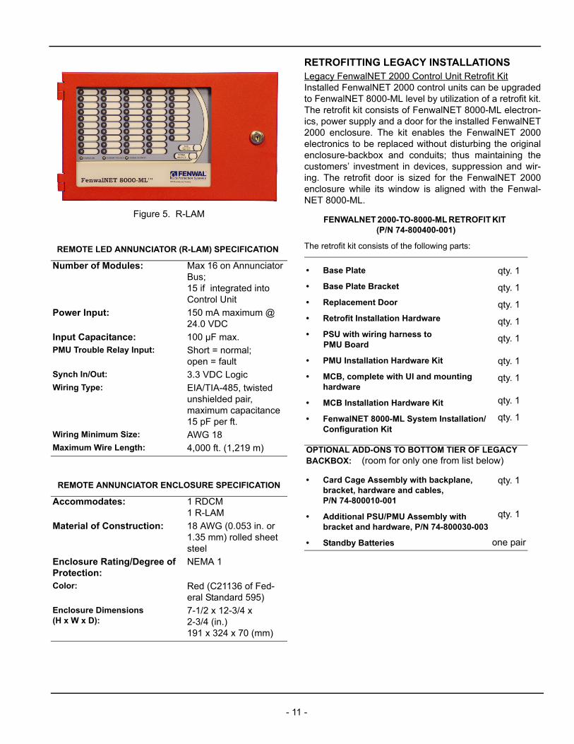
Figure 5. R-LAM
RETROFITTING LEGACY INSTALLATIONSLegacy FenwalNET 2000 Control Unit Retrofit KitInstalled FenwalNET 2000 control units can be upgradedto FenwalNET 8000-ML level by utilization of a retrofit kit.The retrofit kit consists of FenwalNET 8000-ML electron-ics, power supply and a door for the installed FenwalNET2000 enclosure. The kit enables the FenwalNET 2000electronics to be replaced without disturbing the originalenclosure-backbox and conduits; thus maintaining thecustomers’ investment in devices, suppression and wir-ing. The retrofit door is sized for the FenwalNET 2000enclosure while its window is aligned with the Fenwal-NET 8000-ML.
REMOTE LED ANNUNCIATOR (R-LAM) SPECIFICATION
Number of Modules: Max 16 on Annunciator Bus;15 if integrated into Control Unit
Power Input: 150 mA maximum @ 24.0 VDC
Input Capacitance: 100 µF max.PMU Trouble Relay Input: Short = normal;
open = faultSynch In/Out: 3.3 VDC LogicWiring Type: EIA/TIA-485, twisted
unshielded pair, maximum capacitance 15 pF per ft.
Wiring Minimum Size: AWG 18Maximum Wire Length: 4,000 ft. (1,219 m)
REMOTE ANNUNCIATOR ENCLOSURE SPECIFICATION
Accommodates: 1 RDCM1 R-LAM
Material of Construction: 18 AWG (0.053 in. or 1.35 mm) rolled sheet steel
Enclosure Rating/Degree of Protection:
NEMA 1
Color: Red (C21136 of Fed-eral Standard 595)
Enclosure Dimensions(H x W x D):
7-1/2 x 12-3/4 x 2-3/4 (in.)191 x 324 x 70 (mm)
FENWALNET 2000-TO-8000-ML RETROFIT KIT (P/N 74-800400-001)
The retrofit kit consists of the following parts:
• Base Plate
• Base Plate Bracket
• Replacement Door
• Retrofit Installation Hardware
• PSU with wiring harness to PMU Board
• PMU Installation Hardware Kit
• MCB, complete with UI and mounting hardware
• MCB Installation Hardware Kit
• FenwalNET 8000-ML System Installation/Configuration Kit
qty. 1
qty. 1
qty. 1
qty. 1
qty. 1
qty. 1
qty. 1
qty. 1
qty. 1
OPTIONAL ADD-ONS TO BOTTOM TIER OF LEGACY BACKBOX: (room for only one from list below)
• Card Cage Assembly with backplane, bracket, hardware and cables, P/N 74-800010-001
• Additional PSU/PMU Assembly with bracket and hardware, P/N 74-800030-003
• Standby Batteries
qty. 1
qty. 1
one pair
- 11 -
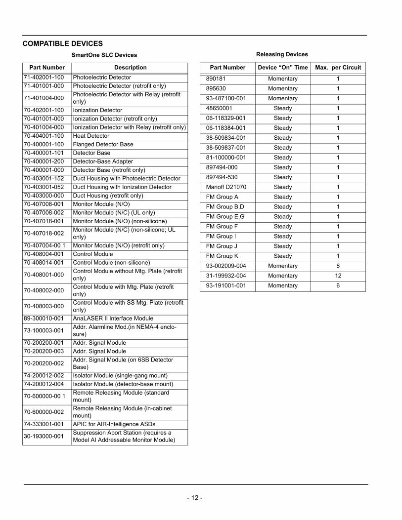
COMPATIBLE DEVICES
SmartOne SLC Devices
Part Number Description
71-402001-100 Photoelectric Detector
71-401001-000 Photoelectric Detector (retrofit only)
71-401004-000Photoelectric Detector with Relay (retrofit only)
70-402001-100 Ionization Detector
70-401001-000 Ionization Detector (retrofit only)
70-401004-000 Ionization Detector with Relay (retrofit only)
70-404001-100 Heat Detector
70-400001-100 Flanged Detector Base
70-400001-101 Detector Base
70-400001-200 Detector-Base Adapter
70-400001-000 Detector Base (retrofit only)
70-403001-152 Duct Housing with Photoelectric Detector
70-403001-052 Duct Housing with Ionization Detector
70-403000-000 Duct Housing (retrofit only)
70-407008-001 Monitor Module (N/O)
70-407008-002 Monitor Module (N/C) (UL only)
70-407018-001 Monitor Module (N/O) (non-silicone)
70-407018-002Monitor Module (N/C) (non-silicone; UL only)
70-407004-00 1 Monitor Module (N/O) (retrofit only)
70-408004-001 Control Module
70-408014-001 Control Module (non-silicone)
70-408001-000Control Module without Mtg. Plate (retrofit only)
70-408002-000Control Module with Mtg. Plate (retrofit only)
70-408003-000Control Module with SS Mtg. Plate (retrofit only)
89-300010-001 AnaLASER II Interface Module
73-100003-001Addr. Alarmline Mod.(in NEMA-4 enclo-sure)
70-200200-001 Addr. Signal Module
70-200200-003 Addr. Signal Module
70-200200-002Addr. Signal Module (on 6SB Detector Base)
74-200012-002 Isolator Module (single-gang mount)
74-200012-004 Isolator Module (detector-base mount)
70-600000-00 1Remote Releasing Module (standard mount)
70-600000-002Remote Releasing Module (in-cabinet mount)
74-333001-001 APIC for AIR-Intelligence ASDs
30-193000-001Suppression Abort Station (requires a Model AI Addressable Monitor Module)
Releasing Devices
Part Number Device “On” Time Max. per Circuit
890181 Momentary 1
895630 Momentary 1
93-487100-001 Momentary 1
48650001 Steady 1
06-118329-001 Steady 1
06-118384-001 Steady 1
38-509834-001 Steady 1
38-509837-001 Steady 1
81-100000-001 Steady 1
897494-000 Steady 1
897494-530 Steady 1
Marioff D21070 Steady 1
FM Group A Steady 1
FM Group B,D Steady 1
FM Group E,G Steady 1
FM Group F Steady 1
FM Group I Steady 1
FM Group J Steady 1
FM Group K Steady 1
93-002009-004 Momentary 8
31-199932-004 Momentary 12
93-191001-001 Momentary 6
- 12 -

ORDERING INFORMATION
Part Number Description
FenwalNET 8000-ML SYSTEMS
74-800100-001 FN8000 Control Unit-3T
74-800101-002 FN8000 Control Unit-3T-ULC
74-800200-001 FN8000 Control Unit-2T
74-800201-002 FN8000 Control Unit-ULC
74-800101-001 FN8000 Control Unit-3T-ULC
74-800201-001 FN8000 Control Unit-2T-ULC
74-800102-001 FN8000 Control Unit-3T-City of Chicago
74-800202-001 FN8000 Control Unit-2T-City of Chicago
EXPANSION ENCLOSURES
74-800100-003 FN8000 Expansion Encl-3T
74-800200-003 FN8000 Expansion Encl-2T
ENCLOSURE TRIM RINGS
74-800100-004 FN8000 Trim Ring-3T Enclosure
74-800200-004 FN8000 Trim Ring-2T Enclosure
74-800300-004 FN8000 Trim Ring-RDCM Enclosure
EXPANSION CARDS
74-800011-001 FN8000 SLC Card
74-800012-001 FN8000 Relay Card
74-800013-001 FN8000 R-NAC Card
74-800016-001 FN8000 City Tie Card
74-800015-001 FN8000 DACT Card
74-800017-001 FN8000 ICM Card
74-800014-001 FN8000 NIC Card
89-300014-001 FN8000 IIM Card (with modem)
89-300015-001 FN8000 IIM Card (without modem)
EXPANSION CARD CAGE
74-800010-001 FN8000 Card Cage Assy
74-800010-002 FN8000 Backplane Board
REMOTE ANNUNCIATORS/MODULES
74-800300-001 FN8000 Remote Display Control Module
74-800300-002 FN8000 Remote LED Annunciator
74-300004-032 FN8000 Model ATM-L LED Driver Module
74-300005-032 FN8000 Model ATM-R Relay Driver Module
STANDBY BATTERIES (order 2 for 24V)
06-115915-013 Battery, 12 Vdc, 7-AH
06-115915-047 Battery, 12 Vdc,12-AH
06-115915-046 Battery, 12 Vdc, 17/18-AH
89-100052-001Battery, 12 Vdc, 35-AH (requires large capacity battery cabinet)
74-600000-514 Large Capacity Battery Cabinet, Red
74-800030-006 FN8000 Battery Tray
EXTERNAL MODULES
74-800300-005 FN8000 FOCM w/enclosure, for MM fiber
74-800300-006 FN8000 FOCM w/enclosure, for SM fiber
74-800300-015FN8000 FOCM Add-On Converter Channel, for MM fiber
74-800300-016FN8000 FOCM Add-On Converter Channel, for SM fiber
74-800300-007 BACnet Module w/enclosure
74-800300-017 BACnet Module Add-On Card
REPLACEMENT ENCLOSURES AND COVERS
74-800101-005 FN8000 Dead Front-3T
74-800201-005 FN8000 Dead Front-2T
74-800100-101 FN8000 3T Main Enclosure
74-800200-101 FN8000 2T Main Enclosure
74-800101-101 FN8000 3T Main Enclosure ULC
74-800201-101 FN8000 2T Main Enclosure ULC
74-800300-101 FN8000 Remote Display Enclosure
MCB & KEYPAD/DISPLAY
74-800020-003 FN8000 Replacement LAM Board
74-800020-001 FN8000 Main Controller Board
74-800020-002 FN8000 Keypad-Display
POWER SUPPLIES
74-800030-001FN8000 PSU, 120-240VAC, 5.4A, with har-ness to PMU Board
74-800030-002FN8000 Power Supply,120-240VAC, 5.4A, without harness
74-800030-004 FN8000 Power Management Unit Board
74-800030-003 FN8000 Add-on Power Supply/PMU Assy.
74-800030-005 FN8000 PMU Assembly Mounting Bracket
74-800030-007 FN8000 Power Management Fuse Kit
MISCELLANEOUS
74-800000-008 FN8000 Installation Configuration Kit
74-800000-001 FN8000 Installation-Hardware Universal
74-800000-004 FN8000 Releasing Diode Kit
74-800500-001 FN8000 Chicago Control Box
74-800000-002 FN8000 Main Plexiglass Window
74-800000-003 FN8000 R-LAM Plexiglass Window
74-800000-005 FN8000 Bezel-Enclosure Door
74-800000-006 FN8000 Harness Enclosure-to-Enclosure
70-600000-100 Hand-Held Programmer
ORDERING INFORMATION (Continued)
Part Number Description
- 13 -
This literature is provided for informational purposes only. KIDDE-FENWAL, INC. assumes no responsibility for the product’s suitability for a particular application. The product must be properly applied to work correctly.
TM
Fenwal is a registered trademark of Kidde-Fenwal, Inc.FenwalNET 8000-ML is a trademark of Kidde-Fenwal, Inc.
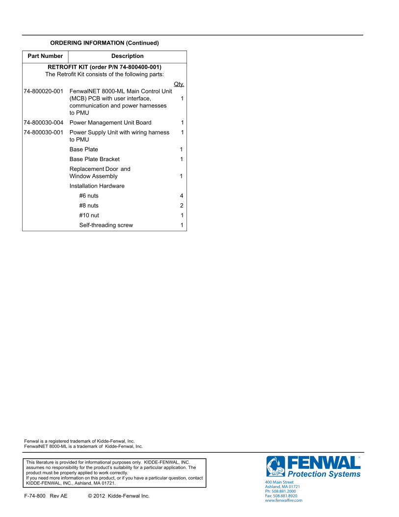
RETROFIT KIT (order P/N 74-800400-001)The Retrofit Kit consists of the following parts:
74-800020-001
Qty.FenwalNET 8000-ML Main Control Unit (MCB) PCB with user interface, 1communication and power harnessesto PMU
74-800030-004 Power Management Unit Board 1
74-800030-001 Power Supply Unit with wiring harness 1to PMU
Base Plate 1
Base Plate Bracket 1
Replacement Door and Window Assembly 1
Installation Hardware
#6 nuts 4
#8 nuts 2
#10 nut 1
Self-threading screw 1
ORDERING INFORMATION (Continued)
Part Number Description
If you need more information on this product, or if you have a particular question, contact KIDDE-FENWAL, INC., Ashland, MA 01721.
F-74-800 Rev AE © 2012 Kidde-Fenwal Inc.
400 Main StreetAshland, MA 01721Ph: 508.881.2000Fax: 508.881.8920www.fenwalfire.com


![Turbine suppression[2]](https://img.pdfslide.us/doc/110x75/546d3cafb4af9f662c8b53ba/turbine-suppression2.jpg)
