Embed Size (px)
Citation preview
Enhanced Thermal Conductivity Ceramic Filled PTFE/WovenFiberglass Laminate for Microwave Printed Circuits Boards
Features:
• “Best in Class” Thermal Conductivity(1.0 W/mK) and Dielectric ConstantStability across Wide Temperatures (-9 ppm/ºC)• Very Low Loss Tangent providesHigher Amplifier or Antenna Efficiency• Priced Affordably for Commercial Applications• Easier to drill than traditional commercial based laminates utilizingthick and dense style woven glass• High Peel Strength for Reliable Copper Adhesion in thermally stressedapplications
Benefits:
• Heat Dissipation and Management• Improved Processing and Reliability• Large Panel Sizes for Multiple CircuitLayout for lowered Processing Costs
Typical Applications:
• Power Amplifiers, Filters and Couplers• Tower Mounted Amplifiers (TMA) andTower Mounted Boosters (TMB)• Thermally Cycled Antennas sensitiveto dielectric drift• Microwave Combiner and Power Dividers
Arlon’s TC350 is a woven fiberglass reinforced, ceramic filled,PTFE-based composite for use as a printed circuit board substrate. TC350 is designed to provide enhanced heat-transferthrough “Best-In-Class” thermal conductivity, while reducing dielectric loss and insertion loss. Lower losses result in higher Amplifier and Antenna Gains/Efficiencies.
The increased thermal conductivity of TC350 provides higherpower handling, reduces hot-spots and improves device reliabil-ity. This higher heat transfer within the substrate complements designs using coins, heat sinks or thermal vias to provide designers additional design margin in managing heat. In designswith limited thermal management options, TC350 significantly improves heat transfer where the primary thermal path is throughthe laminate. This results in reduced junction temperatures andextends the life of active components, which is critical for improving power amplifier reliability, extending MTBF and reducing warranty costs. In addition, lower operating temperatures and chip-matching thermal expansion characteristics provide better reliability for component attachmentprone to solder fatigue, solder softening and joint failure.
TC350 has excellent Dielectric Constant Stability across a widetemperature range. This helps Power Amplifier and Antenna designers maximize gain and minimize dead bandwidth lost to dielectric constant drift as operating temperature changes. Dielectric constant stability is also critical to phase and imped-ance sensitive devices such as network transformers utilized for impedance matching networks utilized in power amplifier circuitryor in Wilkinson Power Dividers.
TC350 has low Z-Direction CTE which matches copper. This feature provides unsurpassed plated through hole reliability.TC350 is a “soft substrate” and relatively insensitive to stress fromvibration and impact from today’s drop testing requirements.
TC350 enjoys a strong bond to copper, utilizing microwave grade,low profile copper. Unlike ceramic hydrocarbons that need to utilize “toothy copper” to achieve acceptable bond, TC350 utilizes relatively smooth copper. This results in even lower insertion loss due to skin effect losses of copper that are more obvious at higher RF and microwave frequencies.
TC350
3.503.503.50
0.00150.00180.0020
-9
7.4x10⁶
1.4x10⁸
3.2x10⁷
4.3x10⁸
780 (31)40
>240
520567>60>60>607, 7231.2
7 (1.2)9 (1.6)7 (1.2)
14/10 (97/69)11/8 (76/55)
0.052.301.0
0.90V0
0.020.010.01
---
----
ppm/ºC
MΩ-cmMΩ-cm
MΩMΩ
Volts/mil (kV/mm)kVsec
°C°Cminminmin
ppm/ºCppm/ºC
%
lb/in (N/mm)lb/in (N/mm)lb/in (N/mm)kpsi (MPa)kpsi (MPa)kpsi (MPa)kpsi (MPa)
-
%g/cm3
W/mKJ/gKclass
%%%
IPC TM-650 2.5.5.3RESONANT CAVITYIPC TM-650 2.5.5.5
IPC TM-650 2.5.5.3RESONANT CAVITYIPC TM-650 2.5.5.5
IPC TM-650 2.5.5.5
IPC TM-650 2.5.17.1IPC TM-650 2.5.17.1
IPC TM-650 2.5.17.1IPC TM-650 2.5.17.1IPC TM-650 2.5.6.2IPC TM-650 2.5.6IPC TM-650 2.5.1
IPC TM-650 2.4.24.6IPC TM-650 2.4.24.6IPC TM-650 2.4.24.1IPC TM-650 2.4.24.1IPC TM-650 2.4.24.1IPC TM-650 2.4.41IPC TM-650 2.4.24IPC TM-650 2.4.24
IPC TM-650 2.4.8IPC TM-650 2.4.8.2IPC TM-650 2.4.8
IPC TM-650 2.4.18.3IPC TM-650 2.4.4
IPC TM-650 2.4.18.3ASTM D-3410ASTM D-3039
IPC TM-650 2.6.2.1ASTM D792 Method A
ASTM D5470ASTM E1461
UL-94
NASA SP-R-0022ANASA SP-R-0022ANASA SP-R-0022A
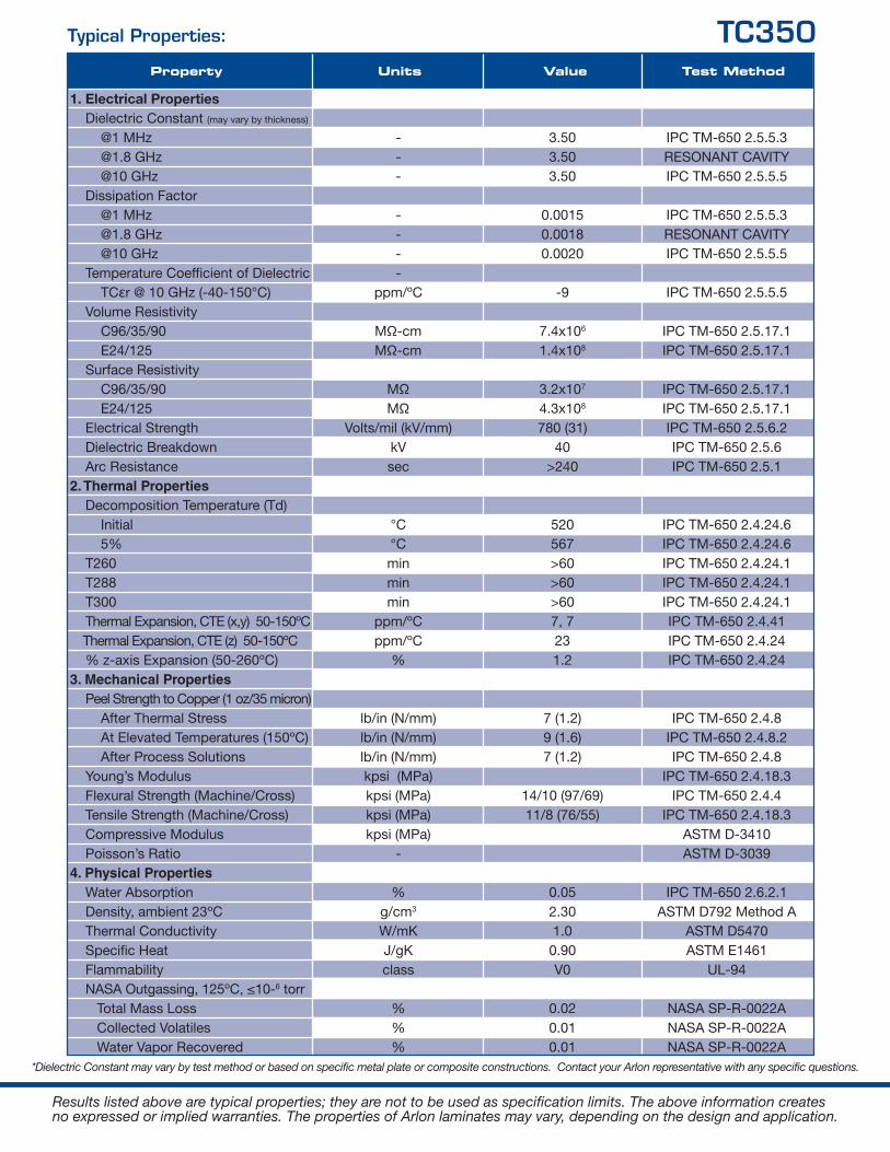
Units Value Test MethodProperty
1. Electrical Properties Dielectric Constant (may vary by thickness)
@1 MHz @1.8 GHz @10 GHz Dissipation Factor @1 MHz @1.8 GHz @10 GHz Temperature Coefficient of Dielectric TCεr @ 10 GHz (-40-150°C) Volume Resistivity C96/35/90 E24/125 Surface Resistivity C96/35/90 E24/125 Electrical Strength Dielectric Breakdown Arc Resistance2. Thermal Properties Decomposition Temperature (Td) Initial 5% T260 T288 T300 Thermal Expansion, CTE (x,y) 50-150ºC Thermal Expansion, CTE (z) 50-150ºC % z-axis Expansion (50-260ºC)3. Mechanical Properties Peel Strength to Copper (1 oz/35 micron) After Thermal Stress At Elevated Temperatures (150ºC) After Process Solutions Young’s Modulus Flexural Strength (Machine/Cross) Tensile Strength (Machine/Cross) Compressive Modulus Poisson’s Ratio 4. Physical Properties Water Absorption Density, ambient 23ºC Thermal Conductivity Specific Heat Flammability NASA Outgassing, 125ºC, ≤10-6 torr Total Mass Loss Collected Volatiles Water Vapor Recovered
*Dielectric Constant may vary by test method or based on specific metal plate or composite constructions. Contact your Arlon representative with any specific questions.
Results listed above are typical properties; they are not to be used as specification limits. The above information createsno expressed or implied warranties. The properties of Arlon laminates may vary, depending on the design and application.
Typical Properties: TC350
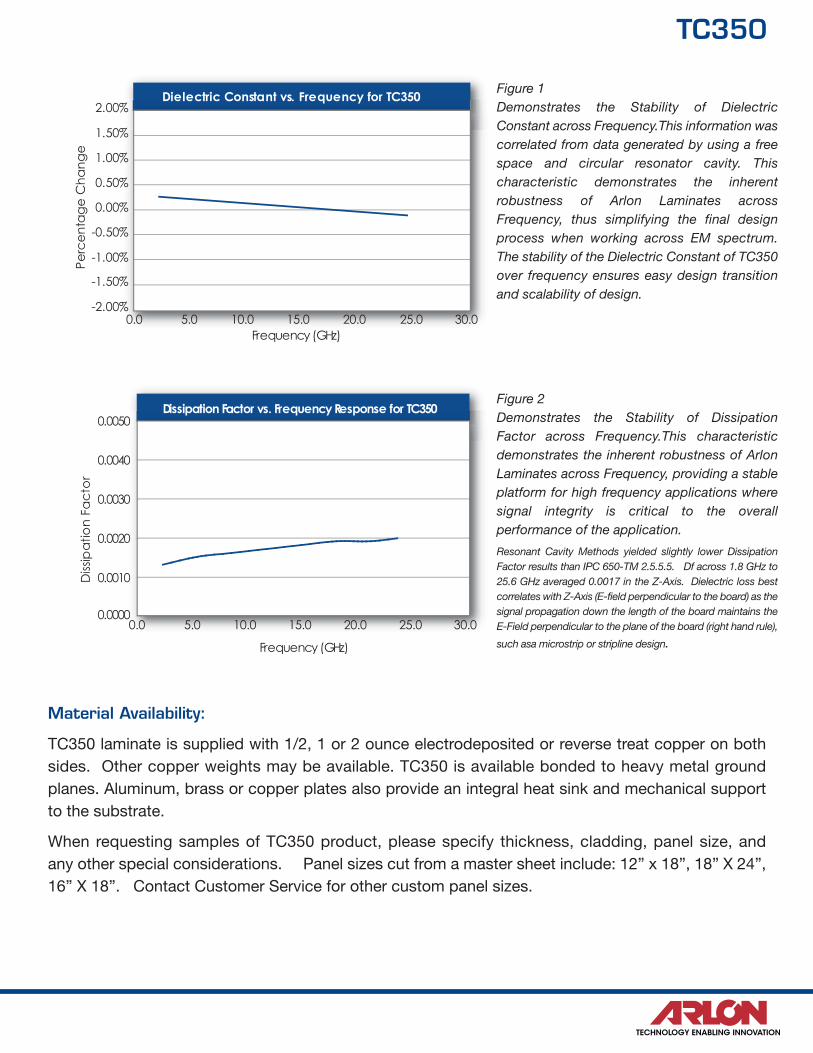
Dielectric Constant vs. Frequency for TC350
-2.00%0.0 5.0 10.0 15.0 20.0 25.0 30.0
-1.50%
-1.00%
-0.50%
0.00%
0.50%
1.00%
1.50%
2.00%
Pe
rce
nta
ge
Ch
an
ge
Frequency (GHz)
D
Dissipation Factor vs. Frequency Response for TC350
0.0 5.0 10.0 15.0 20.0 25.0 30.0
0.0000
0.0010
0.0020
0.0030
0.0040
0.0050
Frequency (GHz)
F
Diss
ipa
tion
Fa
cto
rFigure 1Demonstrates the Stability of Dielectric Constant across Frequency.This information was correlated from data generated by using a freespace and circular resonator cavity. This characteristic demonstrates the inherent robustness of Arlon Laminates across Frequency, thus simplifying the final designprocess when working across EM spectrum.The stability of the Dielectric Constant of TC350over frequency ensures easy design transitionand scalability of design.
Figure 2Demonstrates the Stability of Dissipation Factor across Frequency.This characteristicdemonstrates the inherent robustness of ArlonLaminates across Frequency, providing a stableplatform for high frequency applications wheresignal integrity is critical to the overall performance of the application.
Resonant Cavity Methods yielded slightly lower Dissipation Factor results than IPC 650-TM 2.5.5.5. Df across 1.8 GHz to25.6 GHz averaged 0.0017 in the Z-Axis. Dielectric loss bestcorrelates with Z-Axis (E-field perpendicular to the board) as thesignal propagation down the length of the board maintains theE-Field perpendicular to the plane of the board (right hand rule),
such asa microstrip or stripline design.
Material Availability:
TC350 laminate is supplied with 1/2, 1 or 2 ounce electrodeposited or reverse treat copper on bothsides. Other copper weights may be available. TC350 is available bonded to heavy metal groundplanes. Aluminum, brass or copper plates also provide an integral heat sink and mechanical supportto the substrate.
When requesting samples of TC350 product, please specify thickness, cladding, panel size, and any other special considerations. Panel sizes cut from a master sheet include: 12” x 18”, 18” X 24”,16” X 18”. Contact Customer Service for other custom panel sizes.
TC350
NORTH AMERICA:
Arlon LLCElectronic Substrates9433 Hyssop DriveRancho Cucamonga, CA 91730Tel: (909) 987-9533Fax: (909) 987-8541
Arlon LLCMicrowave Materials1100 Governor Lea RoadBear, DE 19701Tel: (800) 635-9333Outside U.S. & Canada: (302) 834-2100Fax: (302) 834-2574
NORTHERN EUROPE:
Arlon LLC44 Wilby AvenueLittle LeverBolton, Lancashire BL31QEUnited KingdomTel: (44) 120-457-6068Fax: (44) 120-479-6463
SOUTHERN CHINA:
Arlon LLCRoom 601, Unit 1, Bldg 6Liyuan, Xincun ShaheShenzhen, China 518053 Tel: (86) 755-269-066-12Fax: (86) 755-26910475
NORTHERN CHINA:
Arlon LLCRoom 11/401, No. 8Hong Gu RoadShanghai, China 200336Tel/Fax: (86) 21-6209-0202
SOUTHERN EUROPE:
Arlon LLC6 cours des Juilliottes 94700 Maisons-Alfort France Tel: (33) 1-84-23-41-51 Fax: (33) 9-55-62-43-26
For samples, technical assistance, customer service or for more information, please contact Arlon Materials for Electronics Division at the following locations:
www.arlon-med.com
© 2014, 2013, 2012, 2011, 2010, 2009, 2008 Arlon LLC
Arlon Microwave Materials… Challenge Us
Ver. 1.2