Embed Size (px)
Citation preview

72-8715 Operating Manual

72-8715 Operating Manual
1
Overview Digital Bench-Type Multimeter Model 72-8715 is the maximum reading 1999 and 3 1/2 digits, models in manual range, DC / AC current type digital multimeter. This is also the extra large characters in LCD display backlight with full function, full measurement and full overload protection as well as a good product design outlook. In addition to all the conventional features include DC/AC voltage, DC/AC current, resistance, frequency, capacitance, temperature ℃, Transistor hFE, diode and continuity buzzer. This operating manual covers information on safety and cautions. Please read the relevant information carefully and observe all the Warnings and Notes strictly.
Unpacking Inspection Open the package case and take out the Meter. Check the following items carefully to see any missing or damaged part. If you find any missing or damage, please contact your dealer in your country. • Operating Manual 1 piece • Test Lead 1 pair • Alligator Clip 1 pair • K Type Temperature Probe (For the temperature under 230℃testing) 1 piece • Multi-Purpose Socket 1 piece • Power Code (AC220V 50Hz DC9V/200mA) 1 piece
Safety Information This Meter complies with the standards IEC61010-1 in pollution degree 2, overvoltage category (CAT II 1000V) and double insulation. If you can not follow up this operating instruction to use the meter and it reduces the chance to have an using protection.1. Before using the Meter and Test Leads inspect both items. Do not use the Meter and Test Leads if it is damaged or the case (or part of the case) is removed or no reaction on LCD display. Prohibited to use the meter without housing or housing without screw fix up in order to avoid possible electric shock or to avoid possible damage to the meter or to the equipment under test.2. If the damage of test leads, use only the same model number or identical electrical specifications replacement parts.3. Do not use your finger to touch on any testing cable, connector, unused terminal input or circuit during the testing stage4. When the meter working at an effective voltage over 60V in DC or 30V rms in AC, special care should be taken for there is danger of electric shock.5. Selecting the correct terminal input and turn the rotary switch to select the measuring function. In case of no any idea on the value input of the current, just simply test from the high value to low one.6. Do not overload voltage or current on EITHER between terminal and terminal OR between terminal and grounding which indicate on meter limitation.7. The rotary switch should be placed in the right position and no any changeover of range shall be made during measurement is conducted to prevent damage of the Meter.

72-8715 Operating Manual
2
8. Do not use or store the meter in an environment of high temperature, humidity, flammable and electromagnetic environment. The performance of the meter may deteriorate after dampened.9. The internal circuit of the meter shall not be altered at will to avoid damage of the meter and any accident10. Replace the battery as soon as the battery indicator “ ”Appears. With a low battery, the meter might produce false readings that can lead to electric shock and personal injury.11. Turn the meter off when it is not is use and take out the battery when not using for a long time.
General Specifications1. Maximum Voltage between terminal input and COM: 1000V (except 200mV, 230V)2. μA mA terminal input protection: (CE) 250mA 265V auto recovery fuse3. 10A terminal input protection : (CE) F1 (10A H 250V) Fast type melted fuse Φ5x20mm4. Resistance input protection : PTC/250V5. Capacitance input protection : (CE) F2,F3 (0.5A H 250V) Fast type melted fuse Φ5x20mm6. Frequency input protection : PTC/250V7. Temperature input protection : (CE) 250mA 265V fuse8. terminal input protection : PTC/250V9. hFE input protection: (CE) 250mA 265V auto recovery fuse, F3 (0.5A H 250V) Fast type melted fuse Φ5x20mm10. Display LCD full function signal display, maximum reading is 1999 (72-8715), Updates 2-3 times / second11. Range Manual12. Polarity Display: Auto13. Overload indication: 114. Battery Deficiency 15. Operating Temperature: 0 to 40℃16. Storing Temperature: -10 to 50℃17. Relative Humidity: 0℃ to 30℃ below ≤75%,30℃ to 40℃ ≤50%18. Electromagnetic Field: Under 1V/m the influence of radiated radio-frequency electromagnetic field phenomenon,Total accuracy= specific accuracy+ measurement 5%, Over 1V/m radiated radio-frequency electromagnetic which do not have any reference data on this topic.19. Power AC (external power adapter AC220V/DC9V-200mA) or DC(internal battery type 2 R14/1.5V 6 pieces)20. Product size : (300 x 245 x 105) mm21. Product Net Weight : About1500g (without the accessories) 22. Safety Compliances IEC 61010: CATⅡ1000V
LCD Display
72-8715 Operating Manual
3
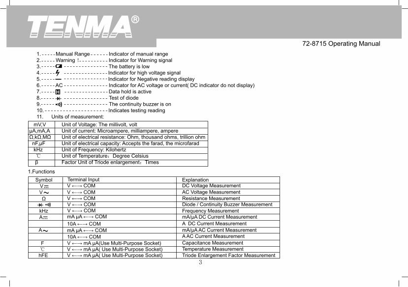
1. Manual Range Indicator of manual range 2. Warning ! Indicator for Warning signal 3. The battery is low 4. Indicator for high voltage signal 5. Indicator for Negative reading display 6. AC Indicator for AC voltage or current( DC indicator do not display) 7. Data hold is active 8. Test of diode 9. The continuity buzzer is on 10. Indicates testing reading 11. Units of measurement: mV,V Unit of Voltage: The millivolt, volt μA,mA,A Unit of current: Microampere, milliampere, ampere Ω,kΩ,MΩ Unit of electrical resistance: Ohm, thousand ohms, trillion ohm nF,μF Unit of electrical capacity: Accepts the farad, the microfarad kHz Unit of Frequency: Kilohertz ℃ Unit of Temperature:Degree Celsius β Factor Unit of Triode enlargement:Times
1.FunctionsSymbol
V V Ω
kHzA
A
F℃hFE
Terminal InputV ←→ COMV ←→ COMV ←→ COMV ←→ COMV ←→ COMmA μA ←→ COM10A ←→ COMmA μA ←→ COM10A ←→ COMV ←→ mA μA(Use Multi-Purpose Socket)V ←→ mA μA( Use Multi-Purpose Socket)V ←→ mA μA( Use Multi-Purpose Socket)
ExplanationDC Voltage MeasurementAC Voltage MeasurementResistance MeasurementDiode / Continuity Buzzer MeasurementFrequency MeasurementmA/μA DC Current MeasurementA DC Current MeasurementmA/μA AC Current MeasurementA AC Current MeasurementCapacitance MeasurementTemperature MeasurementTriode Enlargement Factor Measurement

72-8715 Operating Manual
4
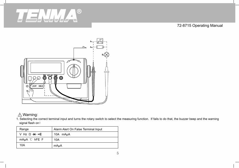
2. Functional Buttons Turn the power on and offLIGHT Turn the display backlight on and off (suitable for battery supply,backlight turn on about 10 seconds after auto shut down.)HOLD Press Hold to enter and exit the hold mode in any mode, the meter beepsOperational Measurement Guide (see Diagram 1, 2, 3)
Diagram 1Diagram 2
72-8715 Operating Manual
5
Diagram 3 Warning: 1. Selecting the correct terminal input and turns the rotary switch to select the measuring function. If fails to do that, the buzzer beep and the warning signal flash on!
RangeV Hz Ω
mAμA ℃ hFE F
10A
Alarm Alert On False Terminal Input10A mAμA
10A
mAμA

72-8715 Operating Manual
6
2. DC or AC Voltage Measurement •. To avoid harms to you or damages to the Meter from electric shock, please do not attempt to measure voltages higher than 1000 V although reading may be obtained! •. The Meter has an input impedance of 10MΩ,This loading effect can cause measurement errors in high impedance circuits and so you need to take a note on it.3. DC or AC Current Measurement
•. Before connect the Meter in serial with the tested return circuit, closed the return circuit current to avoid the dangerous of sparking. •. Do not use over >10A current measurement ! Although the meter can work on below 20A current testing but for the avoiding any harms to you or damages to the Meter !4. Measuring Resistance, Diodes, Continuity or Capacitance •. To maintain the measurement accuracy, discount circuit power and discharge all the high voltage capacitors during the measuring resistance. •. When measuring high resistance on 1MΩ or above, it is normal to take several seconds to obtain a stable reading. In order to obtain stable reading, choose shorter test lead to carrying out measurement. •. The test leads and the Meter inside wire will bring around 0.1Ω to 0.2Ω of error to resistance measurement when measuring low resistance. To obtain accurate readings in low-resistance, short –circuit the test leads beforehand and record the reading obtained, call this reading as X. Then use the equation: measured resistance value (Y) – (X) = accurate readings of resistance. •. During measurement,Diodes is in a good silicon junction drops between 500mV to 800mV as the normal value;The continuity measurement, the poles between resistance is >100Ω,it is a short circuit,but on the poles between resistance is ≤10Ω,it is a good connection,buzzer is continually beep on,and the reading value is nearly to the circuit resistance value,Unit is Ω.
Accuracy Specifications Accuracy: ±(% reading + digits),guarantee for 1 year Operating temperature: 18 to 28℃ Environmental humidity: Less than 75%RH
72-8715 Operating Manual
7
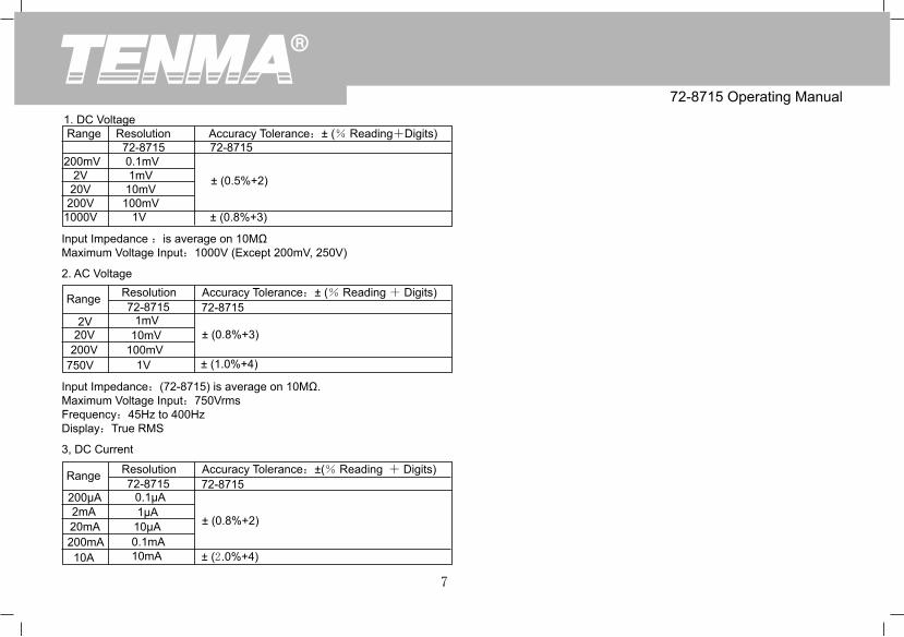
1. DC Voltage Range Resolution Accuracy Tolerance:± (% Reading+Digits) 72-8715 72-8715200mV 0.1mV 2V 1mV 20V 10mV 200V 100mV 1000V 1V ± (0.8%+3)
± (0.5%+2)
Input Impedance :is average on 10MΩMaximum Voltage Input:1000V (Except 200mV, 250V)
2. AC Voltage
Range
Range
Resolution
Resolution
Accuracy Tolerance:± (% Reading + Digits)
Accuracy Tolerance:±(% Reading + Digits)
72-8715
72-8715
± (0.8%+3)
± (0.8%+2)
± (1.0%+4)
± (2.0%+4)
72-8715
72-8715
1mV
0.1μA
10mV
1μA
100mV
10μA
1V
0.1mA10mA
2V
200μA
20V
2mA
200V
20mA
750V
200mA10A
Input Impedance:(72-8715) is average on 10MΩ.Maximum Voltage Input:750VrmsFrequency:45Hz to 400HzDisplay:True RMS
3, DC Current

72-8715 Operating Manual
8
Range
Range
Range
Resolution
Resolution
Resolution
Accuracy Tolerance:±(% Reading + Digits)
Accuracy Tolerance:±(% Reading + Digits)
Accuracy Tolerance:±(% Reading + Digits)
72-8715
72-8715
72-8715
± (1.0%+3)
±(4%+3)
±(5%+5)
± (0.8%+3)
± (2.5%+5)
± (1.2%+5)
72-8715
72-8715
72-8715
1μA
10pF
0.1Ω
10μA
1nF
1Ω
0.1mA
100nF
10Ω
10mA
100Ω1kΩ
10kΩ
2mA
20nF
200Ω
20mA
2μF
2kΩ
200mA
200μF•
20kΩ
10A
200kΩ2MΩ
20MΩ200MΩ
* When ≥5A,Continuous measurement less than 10 seconds at an interval more than 15 minutes.
4, AC Current
Frequency:45Hz to 400Hz* When ≥5A,Continuous measurement less than 10 seconds at an interval more than 15 minutes.
5, Resistance
6. Capacitance
*:>40μF capacitance measurement as reference purpose.

72-8715 Operating Manual
9
7. Frequency
Range
Range
Range
Resolution
Resolution
Resolution
Accuracy Tolerance:±(% Reading + Digits)
Remarks
Remarks
Accuracy Tolerance:±(% Reading + Digits)
72-8715
±(1.5%+5)
Open circuit voltage is around 3 V,Silicon junction drops between 0.5 to 0.8V as the normal value.
Open circuit voltage is approximate 3V;When circuit disconnected with resistance value:>100Ω,buzzer does not beep;When circuit is in good connection with resistance value :≤10Ω,buzzer beeps continuously.
72-8715
72-8715
72-8715
1Hz100Hz
1mV
1Ω*
2kHz200kHzInput Amplitude:(2kHz range)50mV≤a≤30Vrms, (200kHz range) 150mV≤a≤30Vrms
8. Temperature
Range
-40 to -20℃>-20 to 0℃>0 to 100℃>100 to1000℃
1℃
72-8715 72-8715-(8%+5)
±(1.2%+4±(1.2%+3)±(2.5%+2)
Resolution
* Thermocouple: It is suitable to use K type thermocouple. This include point contact K type thermocouple can only be used on less than 230℃ temperature measurement.
9. Diode Test
10. Continuity Test

72-8715 Operating Manual
10
Range
hFE
ResolutionRemarks
Ib0 is about 10μA;Vce is about 2.5V
72-8715
1β*
11. Transistor hFE
see Diagram 4
Specifications and other information shown on this instruction manual are subject to change without notice
Diagram 4

Copyright 2010 Tenma. All rights reserved. Manufacturer:Tenma 405 S. Pioneer Blvd, Springboro, Ohio 45066-3001 Phone: 1-888-655-5409 Fax: 1-800-765-6960
REV.1DATE:2015-12-15P/N:110401105612X
72-8715 Operating Manual
11

序号 项目 内容
1
2
3
4
5
6
7
尺寸 尺寸:210X145mm
材质 80g书纸
颜色 单黑印刷
外观要求
装订方式 两枚大钉钉装
表面处理 无
印字完整清晰、版面整洁,无斑墨、残缺破损、毛边、装钉不齐等缺陷。
修改
DWH设 计 MODEL
机型:Part NO.物料编号:110401105612X CHK
审核
APPRO. 批准
说明书菲林做货要求:
8 REV. 2
72-8715(UT801改)
版本.1 韦英锁2015/12/151.修改前物料号:110401101889X2.修改第7页的AC Voltage 参数3.最后一页增加PN号