Embed Size (px)
Citation preview
US DEPARTMENT OF TRANSPORTATION 710091) FEDERAL AVIATION ADMINISTRATION
121103
SUBJ STANDARD TERMINAL ARRIVAL PROGRAM AND PROCEDURES
1 PURPOSE This order provides guidance and standardization for procedures development and management of the Standard Terminal Arrival (STAR) program
2 DISTRIBUTION This order is distributed in Washington headquarters at the division level of Flight Standards branch level of Air Traffic the offices of Airport Safety and Standards and Communications Navigation and Surveillance Systems the National Flight Procedures Office (NFPO) the Regulatory Standards and Compliance Division at the Mike Moruroney Aeronautical Center regional Eight Standards and Air Traffic Divisions (ATD) all air traffic field offices and facilities and special military and public addresses
3 CANCELLATION This ordta cancels Order 71009C Standard Terminal Arrival dated November 14 2001
4 EFFECTIVE DATE This order is effective December 15 2003
5 BACKGROUND The STAR program was developed to reduce pilotcontroller workload and airground communication s by providing a preplanned arrival pioceduie published in graphic form STARs should be simple understandable and applicable to current air traffic control (ATC) radarnonradar operations This order provides guidelines that standardize the development and publication of conventional and area navigation CRNAV) STAR procedures
6 EXPLANATION OF CHANGES This order has been revised and updated to reflect the most current STAR program information and has been harmonized with Order S26Q46 Departure Procedure Program dated January 2 2003 to the greatest extent possible
a Related publications have beenreferenced including the notices to airmen and Flight Management System instrument procedures development orders Federal Aviation Administration (FAA) air traffic noise screening model user manual International Civil Aviation Organization (ICAO) documents and Radio Technical Commission for Aeronautics (RTCA) publication on Required Navigation Performance (RNP) for RNAV Minimum Aviation Systems Performance Standards (MASPS)
b The format has been revised to clarify the conventional and RNAV STAR development processes
c Roles are clearly defined responsibility details are expanded to emphasize specific processing responsibilities and the Regional Airspace Procedures Team (RAPT) was added
Distrbjtior ZAT-T^O A-FATFFSFIA-Q (MAX) Initiated By ATP-500 2AT-721 2AT-423 External
71009D 121103
d Requirements for visual flight rules (VFR) sectional charts and notices (o airmen (NOTAM) have been clarified
c Figures have been added to Appendix 2 Guidelines for Design of Standard Terminal Arrivals of this order to visually identity RNAV STAR transitions Forms 7100-3 RNAV STAR (Data Record) and 7100-4 STAR Standard Terminal Arrival and their associated instructions have been modified and are contained in Appendix 3 Instmcfions for Completing RNAV Star Form 7100-3 and Appendix 4 Instructions for Completing Form 7100-4 respectively Guidelines for Implementing Terminal RNAV Procedures is included in Appendix 5 Guidelines for Implementing Terminal RNAV Procedures
f Adds distance measuring equipment (DME) assessment requirement
g Simplifies procedures by limiting segments to en route and common route and eliminating runway transitions
7 DEFINITIONS Appendix 1 Acronyms Terms and Definitions contains a glossary of additional terms abbreviations and acronyms used in this order
8 RELATED PUBLICATIONS
a Order 10501 Policies and Procedures for Considering Environmental Impacts
b Order 71303 Holding Pattern Criteria
c Order 74002 Procedures for Handling Airspace Matters
d Order 79302 Notices to Airmen (NOTAM)
e Order 82603 United States Standard for Terminal Instrument Procedures (TERPS)
f Order 826019 Flight Procedures and Airspace
g Order 826040 Plight Management System (FMS) Instrument Procedures Development
h Order 826043 Flight Procedures Management Program
i Order 826044 Civil Utilization of Area Navigation (RNAV) Departure Procedures
j Order 826046 Instrument Departure Procedure (DP) Program
k FAA-EE-99-01 ATMS Air Traffic Noise Screening Model Version 20 User Manual
ARENJC Specification 424 Navigation System Databases
m ICAO Annex 11 Air Traffic Sei vices
Page 2 Par 11
121103 71009D
n ICAO ATM 4444 PANS OPS
o RTCA DO-236A MASPS RNP for RNAV
9 FORMS Appendix 3 contains Form 7100-3 and Appendix 4 contains Form 7100-4
10 REGIONAL STAR PROCEDURES PROCESSING AND CANCELLATIONS
a General The following guidance outlines procedures for STAR requests processing and cancellations
STAR Requests STARs are typically requested by the responsible air route traffic control center (ARTCC) servicing the terminal area approach control for the areaairport(s) affected by the terminal radar approach control facility or by other proponents These requests shall be routed to the RAPT for processing in accordance with Order 826043
b The proponents request shall include
(1) Expected benefits to include advantages resulting from the implementation of a STAR such as fuel savings from reduced flight tracks and time reduced interintra-facility coordination reduced communications increased aiispaceflexibility management and sectorization or other similar benefits to users or providers
(2) Description of the STAR including the proposed ground track with navigational aids (NAVALD)fixesT waypoims (WP) courses radials and altitudesspeeds
c STAR Processing (following RAPT authorization)
(1) For RNAV STARs the regional ATD shall form an RNAV working group in accordance with this order The working group shall use Guidelines for Implementing Terminal RNAV Procedures (included in Appendix 5) and the Terminal Area Route Generation Evaluation Traffic Simulation (TARGETS) design tool
(2) Conventional STARs are the responsibility of the controlling ARTCC for piocedure design development and implementation in accordance with this order
(a) TARGETS may be used for procedure design
(b) Altitude and speed assignments must be designed and coordinated with the lead operator and the ATC facilities having jurisdiction for the airspace affected
d Cancellation A proponents recommendation for cancellation shall include notification to the ATC facilities impacted STARs may be canceled by ATC or military service as appropriate after coordination with the RAPT
Par 11 Page 3
71OO0D 12 1303
11 ROLES AND RESPONSIBILITIES
a The ATD shall
() For RNAV STAR development
(a) Designate a project facilitator and a TARGETS operator
(b) Direct the formation of an RNAV Implementation Working Group with stakeholder representation as identified in Table 1 of Appendix 5 Guidelines for Implementing Terminal RNAV Procedures
(2) For RNAV or conventional STAR development
(a) Use the information contained in Appendix 2 for guidance on STAR design and development
(b) Ensure coordination with affected ATC facilities Provide assistance to ATC facilities where local training and resources are not available
(c) Review each new or revised STAR to ensure accuracy and compliance with the provisions of this order
(d) Use ihe information contained in Appendix 5 for guidance in review and approval of environmental data and documentation Send the preliminary environmental package to the air traffic environmental specialist for review to ensure that proper environmental guidance has been applied to the proposed procedure unless the AT environmental specialist is part of the RNAV Implementation Working Group
(e) Send procedure documentation to the Flight Procedures Office (FPO) The documentation includes the following
L Original signed Form 7100-4 and two additional copies
2 Form 7100-3 (for RNAV STARs)
3 Two copies of each Form 8260-2 Data Worksheet
4 TARGETS Distribution Package (for RNAV STARs)
1 RNAV-Pro Output Package (for RNAV STARs)
6 Theresults of the regional environmental review
T The VFR sectional charts depicting the STAR route the route protected areas and the controlling obstructions for each segment For conventional STARs provide only for off airway routing
Pagcopy 4 Par 11
121103 71009D
5L The air traffic facility point of contact
(f) After receipt of completed documentation from the NFPO forward copies to all affected ATC facilities
(g) Subsequent modification of the procedure requires forw aiding of the appropriate 7100 series form to effect permanent charting changes
b The ATC facility shall for RNAV or conventional STAR development
(1) When requested by the RAPT andor ATD provide assistance to determine the STAR operational feasibility and verify expected benefits
(2) When requested^ provide the working group with information pertaining to traffic flows and operational constraints ie arrivaldeparture routes aircraft types and characteristics minimum instrument flight rules (DPR) altitudes airspace boundaries sector requirements and standard operating procedures (SOP)
(3) Where local training and resources permit when directed by the RAFF or ATD provide personnel and resources to support the STAR development and implementation Seek assistance from the ATD where training and resources are not available
(4) Provide Automated Radar Terminal System (ARTS) or Standard Terminal Automation Replacement System (STARS) data and identify required video maps if necessary ARTSSTARS data should be provided during all phases of the design process as necessary ie design testing implementation etc
(5) Coordinate with othex ATC facilities concerning letters of agreement handoff procedures controller notifications and SOPs
(6) Review automation requirements ie Host Computer System (HCS) ARTSSTARS update cycles moratoriums coding options etc and coordinate with adjacent facilities regarding HCS automation change
(7) Serve as the focal point for all ATC related coordination and provide assistance in resolving problems identified during the development process
(8) Ensure that the proposed procedure has been evaluated for potential environmental impacts in accordance with Order 10501 in order to meet the requirements of the National Environmental Policy Act An approved environmental checklist and the Air Traffic Noise Screening (ATNS) Model shall be used for this purpose Close coordination is required with the terminal procedures specialist and regional air traffic environmental specialist to ensure compliance with applicable environmental laws regulations and policies
(9) Name all fixes and WPs in a STAR Coordinate with the controlling ARTCC to obtain the five-letter pronounceable names Complete Form 8260-2 m accordance with Order 826046 for each fix or WP being established modified or canceled and submit to ATD
Par 11 Page 5
71009D 121103
(10) Depict each RNAV STAR oroff airway conventional STAR procedure on a VFR aeronautical sectional chart(s) for each segment at or below flight level (FL) 180 m the contiguous United States and at or below FL 230 for Alaska and Hawaii (other approved electronicdigital mapping tools may be used eg TARGETS)
(a) The depiction will include the STAR primary (4 nautical miles [KM]) and secondary (2 NMs) obstruction areas on either side of course centcrline (refer to Orders 826044 and 82603) and must include identification of the obstacle used to establish the minimum en route 3FR altitude for each segment Where two segments are joined no turning area is required (see figure 1)
(b) Coordinate with the FPO for application of appropriate orders and assistance developing chart depictions
NOTE-The purpose of this requirement is to enable NFPO to verify that minimum en route altitudes (MEA) meet minimum required obstruction clearance altitude minimum reception aliitedet communication and airspace requirements
FIG I STAR Route Stegmmt Overlap
(11) Shall complete an initial DMEDME screening using the RNAV-Pro modeling tool Assistance in completing the DMEDME screening is available from the regional ATD Forward the RNAV-Pro Output with the submission package
(a) Unless a satisfactory assessment of the DME NAVAID infrastructure is obtained the procedure must be annotated GPS Required The assessment ensures that adequate NAVAED availabilitycoverage exists to support navigation along the published route
(b) If following the flight inspection any DME facility limitations are identified a final ran of RNAV-Pro will be conducted with the UKIE limitations included
Paoe6 Parti
121103 71009D
(c) When icquired request Expanded Service Volume (ESV) through the ESV Management System (ESVMS) The ESVMS is accessible via the Spectrum Assignment and Engineering Division ASR-100
(12) In collaboration with the RNAV working group complete and forward the applicable forms environmental checklist ard annotated VFR sectional chart(s) to the ATD The applicable form for a conventional STAR is Form 7100-4 and the applicable forms for an RNAV STAR are Forms 7100-3 and 7100-4 (see appendixes 3 and 4)
(13) Conduct as a minimum a biennial review of existing STARs for accuracy simplicity standardization obsolescence and adherence to criteria in this order and the latest edition of Orders 82603 and 826019 Forwaid changes or updates to the ATD
(14) When it is necessary to cancel a STAR process appropriate Forms 7100-4 and 8260-2 After completion distribute to RAPT ATD National Flight Data Center (NFDC) NFPO and affected ATC facilities
c The RNAV Implementation Working Group shall
(1) Follow Guidelines for Implementing Terminal RNAV Procedures in Appendix 5
(2) Follow Guidelines for Design of Standard Terrmna Arrivals m Appendix 2
d The FPO shall
(1) Provide technical assistance on STAR development and review procedure desip for compliance with criteria
(2) Review STAR documentation The review shall include as a minimum the following
(a) Evaluation for impact by current or proposed obstacle evaluationsairport airspace analysis facilities and equipments national change proposals or other applicable projects
(b) Conduct database integrity checks (WP fix etc) to ensure accuracy of the data coordination of WPfix names and to confirm no other fixes or WPs are located at the same geographic location
(3) The FPO shall contact the submitting ATC facility to resolve any problems found during the review The working group and ATC shall be responsible for additional coordination of changes identified during the review process
(4) Facilitate discussion of the STAR at the RAFf
(5) Transmit the S TAR documentation to the NFPO
Par 11 Pago 7
710Q9D 121103
e The All Weather Office (AWO) shall
(1) Piovide technical assistance on STAR development
(2) Provide assistance in determining the equivalent level of safety required for any flight standards waivers needed
f The NFPO shall
(1) Review STAR documentation and conduct data integrity check for existing facilities (WP fix etc) against the data contained in the approved database for continuity This is to ensure accuracy of the data coordination of names and to eonOrm no other fixes or WPs are located at the same geographic location
(2) Review the STAR for MEA and bearingdistance between fixesWP
(3) After the package is complete forward STAR documentation to Flight Inspection Central Operations for coordination of the flight inspection
(4) Complete Form 8260-2 based on the submitted worksheets
(5) Forward documentation of flight inspection and original forms to the NFDC for further processing and a copy to the regional ATD Critical DME facilities as identified by fliglit inspection shall be annotated on the Form 7100 4 in block 15
g The NFDC shall
(1) Conduct a prepublication review of submitted forms to ensure compliance with applicable directives and resolve data conflicts form discrepancies etc with the NFPO and regional ATD
(2) Verify that WP names are not duplicated
(3) Assign an effective date and publish the STAR and associated fixesWP in the National Flight Data Digest (NEDD) authorizing charting agencies to publish the STAR
(4) File and maintain the original signed copy of the forms
(5) When a STAR or WP is cancelled emure names are made available for future use
h The NACO shall
(1) Advise the RAPT and ATD of any charting issues or publication delays
(2) Publish the STAR on the effective date assigned by NFDC
Page 8 Par 11
121103 71009D
12 ACCURACY VERIFICATION AND RESPONSIBILITIES Users of this order shall notify the NFDC flight service station or local air traffic unit for possible NOTAM action whenever errors are discovered in the NFDD or when reviewing a STAR
a STAR NOTAM Issuance
(1) Order 79302 prescribes procedures used to obtain formal and disseminate information on unanticipated or temporary changes to components of or hazards in the National Airspace System until the associated aeronautical charts aod related publications have been amended The NOTAM system should not be used to advertise data already published or charted
(2) When changes occur so rapidly that time does not permit issuance on a chart or in an appropriate pubication they are publicized as NOTAMs Originators of airmen information are expected to inform the NFDC in sufficient time before the effective dates of changes to permit publishing of aeronautical data on the various charts or in the appropriate publications
(3) Information pertaining to temporary changes in published STARs and profile descent procedures shall be submitted to the United States NOTAM Office (USNOF) for dissemination as NOTAM D
USD XKDCKX BOS SCUFF THREE ARRIVALRAALF TRANSITION DELETE SEGMENT FROM JFK VORDME TO RAALF INT CHANGE INITIAL ROUTING TO READ FROM OVER RAALF INT VIA ORW VORDME R-261 TO OKW VORDME REST OF ROU1E UNCHANGED
(4) Changes to STARs requiting immediate dissemination shall be originated by the affected ARTCC and submitted to the USNOF for issuance as a NOTAM D
b Permanent Changes Appropriate Forms 7100-4 and 7100-3 must be submitted to effect permanent charting changes NOTAMs on STARs will be carried on the system until published Upon formal publication of the amended STAR the facility that submitted any applicable NOTAMs shall ensure they are cancelled through the USNOF
13 MILITARY STARS Military STARs are developed and published in the same manner as civil STARs and shall comply with the criteria outlined in this order Miliary proponents are responsible for ensuring coordination with the RAPT and affected ATC facilities TheFAA will develop STARs at joint-usefalffieTtis I
David B Johnson Director of Air Traffic
Par 11 Page 9
121103 7100 9D Appendix 1
APPENDIX 1 ACRONYMS TERMS AND DEFINITIONS
AcronymTerra
AAO
APP CON
Area Navigation (RNAV)
ARTCC
ARTS
ATC
ATCT
ATD
ATIS
ATNS
AWO
AWOS
CP
Common Route
DF
DME
En Route Transition
FAA
Beltairiba
Adverse assumption obstacle - The means by which an obstruction is identified when no man-made obstruction is recorded or identified
Approach control
A method of navigation that permits aircraft operation on any desired flight path within the coverage of station-referenced navigation aids or within the limits of the capability of self-contained aidsf or a combination of these (See Pilot Controller Glossary)
Air route traffic control center
Automated Radar Terminal System
Air traffic control
Airport traffic control tower
Air Traffic Division
Automated Terminal information System
Air Traffic Noise Screen model
All weather operations
Automated Weather Observation System
Course to fix RNAV leg type
The segment of a STAR between the en route transition end point and the final point on a STAR
Direct to fix RNAV leg type
Distance measuring equipment
A published segment that connects one or more en route airwayjet route to the STAR
Federal Aviation Administration
Page 1
7100SD 121103 Appendix
Fix A generic term used to define a predetermined geographical position used for route definition A fix may he aground-based NAVAJD a waypoint or defined by reference to one or more radio NAVAIDs
FB Fly-by waypoint - Requires the use of turn aniicipiition to avoid overshoot of the next flight segment
FO Fly-over waypoint - Precludes any turn until the waypoint is overflown
and is followed by an intercept maneuver of the next flight segment
FMS Flight Management System
FPNM Feet per nautical mile
FPO Flight Procedures Office (An element of the National Fliglit
Procedures Office located at each FAA regional headquarters)
FSS Flight service station
GPS Global Positioning System
HCS Hos Computer System IF Path terminator denoting the initial fix of an RNAV route leg
See path and terminator
IFR Instrument flight rules
KIAS Knots indicated airspeed
KTS Knots Lead Operator An operator that has agreed to serve as the focal point for the development
of STARs at a specific airport The lead operator agrees to help develop the STAR and ensure fly-ability by all aircraft expected to use the STAR
Leg Type See path and terminator
I OA Letter of agreern ent
MEA Minimum en route IFR altitude
MSL Mean sea level
NACO National Aeronautical Charting Office
NAVAID Navigational aid
Page 2
123103
NEPA
NFDD
NFDC
NFPO
NOTAM
NM
NRP
Path and Terminator
Proponent
RAPT
RNP
Significant Benefits
SOP
STAR
TARGETS
TERPS
TF
710Q9D Appendix 1
National Environmental Policy Act
National Flight Data Digest
National Fliglit Data Center
National Flight Procedures Office
Notice to airmen
Nautical mile
North American Route Program
An ARINO 424 term that is defined as a set of two alphabetic characters The first identifies the type of flight path and the second indicates where the route leg terminates eg TF DF CF VM
The originator of a STAR requirement This may include an individual user group ATC NFPO or other appropriate government agency
Regional Airspace Procedures Team
Required navigation performance A statement of the navigational performance accuracy necessary for operation within defined airspace
Standard instrument approach procedure
Tangible or intangible advantages resulting from the implementation of a STAR such as fuel savings from reduced flight tracks and time reduced mterintra facility coordination reduced communication between ATC and pilots increased flexibility of airspace management and sectorizalion due to more predictable ground tracks or other similar benefits to users or ATC
Standard operating procedures
Standard Terminal Arrival - A preplanned instrumentfliglit rule (IFR) air traffic control arrival procedure published for pilot use in graphic form STARs provide transition from the en route structure to an outer fix or an instrument approach fixarrival waypoint in the terminal area
Terminal Area Route Generation Evaluation Traffic Simulation tool
1 erniinal instrument procedures
Track to fix
Page3
71009D
Appendsx 1 3 2 1103
TRACON Terrainal radar approach control facility
Transitions See common route and en loute transition VFR Visual flight rales
VM Heading to a manual termination (sped fled as a heading until a manual termination)
WP Waypoint - A predetermined geographical position used for routeinstrument approach definition progress reports pubhshed WR routes visual reporting points or points for transitioning andor circumnavigating controlled andor special use airspace that is defined relative to a VORTAC station or in termamp uflatitudelongitiide coordinates
Page A
121103 71039D Appendix 2
APPENDIX 2 GUIDELINES FOR DESIGN OF STANDARD TERMINAL ARRIVALS
1 GENERAL Safety is a primary concern in the design of Standard Terminal Arrival (STAR) routes A STAR will not be established solely for the purpose of noise abatement but existing noise abatement procedures should be considered in the STARS design In addition all procedures shall be evaluated for possible environmental effects in accordance with Order 10501 Policies and Procedures for Considering Environmental Impacts to ensure that the requirements oftbe National Environmental Policy Act have been met An environmental checklist and the Air Traffic Noise Screening model shall be used for this purpose Close coordination is required with the terminal procedures specialist and regional air traffic environmental specialist to ensure compliance with applicable environmental laws regulations and policies
a STARs shall
(1) Be simple and easily understood
(2) Commence at an en route fix eg navigational aid (NAVAJD) intersection distance measuring equipment (DME) fix or waypoint
(3) Be compatible with local air traffic control (ATC) standard operating procedures (SOP) and traffic flow management procedures
(4) Include in the graphic depiction holding patterns referenced in the narrative of the STAR
(5) Be designed to Level 2 criteria as defined in Order 826044 Civil Utilization of Area Navigation (RNAV) Departure Procedures (RNAV only)
(6) Shall not require automated vertical navigation
(7) Depict a minimum en route altitude (MEA) for each segment of an arrival m accordance with Order 82603 United States Standard for Terminal Instrument Procedures The MEA of each segment shall not be higher than the preceding segment In mountainous areas obstacle clearance may he reduced from 2000 feet to 1000 feet when necessary to achieve compatibility with the associated instrument appioach procedures (TAP) with approval from the National Flight Procedures Office
(8) Terminate at an initial approach fix for a standard instrument approach procedure (SIAP) or at a point in space defined by a fix or waypoint An RNAV STAR shall terminate at a point from which radar vectors may be initiated For airports served by a radar approach control terminate at a point within the terminal airspace
(9) When terminating at a point in space that is not associated with an f AP be charted with air traffic vectors and lost communication instructions if lost communications procedures differ from 14 Code of Federal Regulations (CFR) 91185
Paqo 1
71009D Appendix 2 121103
(10) Not combine conventional and RNAV STARs on the same chart
(11) Use procedural data notes when limitations are necessary eg services to be provided in conjunction with the procedure designated aircraft equipment eapabilitys etc Do not include items of an ATC clearance in notes
ExampleshyRADAR REQUIRED or FOR USE BYE t A3 andR (RNP-20) EQUIPPED AIRCRAFT ONLY
b STARs should
(1) Be developed to accommodate as many different types of aircraft as possible
(2) Provide for a significant usersystem benefit
(3) Reduce pilotcontroller communications and workload
(4) Use only the minimum number offixeswaypomts turns and speed or altitude changes to depict the route
(5) Avoid the use of DME arcs
(6) Establish crossing altitudes for traffic separation andor obstacle clearance
c STARs may
(1) Serve multiple airports
(2) Be designed to overlay the vector procedure from an en route fix to a point in space orSIAPfix
2 RNAV STARs This section describes the elements specific to RNAV STAR procedures The design of an RNAV STAR may include two segment types en route transitions and a single common route (see figure 1) These segments will be depicted with poundy-by (FB)fly-over (FO) waypoints (that may have associated altitude and speed requirements) and leg types
Page 2
H009D 121103 Appends 2
FIG J
RNAV STAR Example
PEPPR
SAIL
RUNNR jSPSEJBu]
0ANCR Vectors to TABLE OME RNAV ARRIVAL Final (TBLT8L1)
RNAlTifA^WrTH THREE EN ROtTE n
TRANSITIONS AMD VECTORS TO FINAL
a Waypoints An RNAV STAR must be designed using waypoints This provision does not preclude the use of an existing NAVAJDfix FB waypoints shall be used except the last waypoint shall be coded as aFO waypoint
(1) Design STARs using the fewest number of waypoints
(2) Names assigned ibi waypoints shall consist of a singlefive-letter pronounceable name
(3) Use existing NAVATDsfixes or waypoints whenever possible Waypoints that are co-located with existmg NAVATDs shall use the NA VATD three-letter location identifier
(4) Waypoints may be assigned crossing altitudes and speeds to optimize the descent and deceleration profiles Waypoint crossing assignment types shall be defined as at at or above at or below or expect
(a) Limit the number of altitude and speed requirements to the minimum necessary Altitude assignments shall not include both at or above and at or below in the same procedure Expect altitudes or airspeeds will not be coded into an aircraft navigation database
Page 3
71009D Appendix 2 12 11 03
(b) Avoid the use of multiple altitude or speed restrictions at same waypoint egbdquo cross XRAY at 9000 feet when Runway 27 in use but cross XRAY at 11000 feet when Runway 9 is active When multiple restrictions cannot be avoided at a particular waypoint use expect altitudes oi speeds This does not prohibit the combined use of a single altitude and a single speed assignment for a waypoint
b Leg type (path terminator) The following table shows permissible leg types for use with RNAV STARs (refer to Order 826044 for leg-type definitions and examples)
TBLl Leg-Type Example
(From Waypoint Via (leg type) To Waypoint lt FB TFCF FBFO Irp2 T X C F T D F FBFO
VM3jFO wsiisiSiiiiHi
(1) Track to fix (TF) is the preferred leg type from an FB to a FBFO
(2) An IF is used to designate the first waypoint of a STAR transition
(3) A heading until a manual termination (VM) leg may be used only after the last waypoint A VM leg shall be atabove the minimum vectoring altitude
c Leg Length
(1) Use the longest legs possible The designer must consider speed and course changes when determining minimum kg length (refer to Order 826044 for specific minima)
(2) The maximum leg length for straight-line paths is 260 miles to ensure the geodesic path does not exceed the protected airspace for a great circle path
d Turn Angle
(1) For a track change at a FB waypoint below flight level (FL) 195 avoid turn angles of greater than 120 degrees
(2) For a track change at a FB waypoint at or above FL 195 avoid turn angles of greater than 70 degrees
c Descent Gradients and Deceleration Segments
(1) STAR procedures should be designed to standardize descents from the high-altitude en route stratum down to the terminal environment
Page laquo
F1C09D 121103 Appendix 2
(2) A descent gradient of 318 feet per nautical mile (FPNM) (a 3-degree vertical path angle [VPA]) should be used from the en route environment to 10000 feet mean sea level (MSL) Below 10000 feet MSL the descent gradient should not exceed 330 FPNM (a 31-degree VPA)
Note-Based on ATC SOPs RNA V STARs may require descent gradients that exceed the 330 FPNM
A descent gradient greater than 330 FPNM may require manual speed intervention by the pilot and deceleration segments may need to he increased to compensate
(3) The STAR designer shall allow for a deceleration at any waypoint that has a speed restriction The operational requirement of affected operators should be considered As a general deceleration guideline the leg distance between the waypoints should be increased at least 1 nautical mile (NM) per 10 knots (KTS) of deceleration required
Example-An RNAV STAR begins at waypoint ALPHA at 17000feet MSL and 310 KTS This STAR requires the aircraft to descend to and cross waypoint BRAVO at 9000feet MSL at 240 KTS The minimum leg length between ALPHA and BRAVO would be computed as follows
(17000 - 9000) + 318 = Minimum leg length using a 3-degree descent gradient 8000 +318^ 25157NM
plus
(310 - 240 + 10 - Deceleration segment 70 + 10-7NM 7 = 32J57 NM (round to 3216)
(4) STAR design should account for the deceleration necessary to slow the aircraft to 250 KTS at 10000 feet MSL If the STAR ends within 20 miles of a landing runway the STAR should also provide a deceleration segment that allows for a speed reduction from 250 KTS to 200 KTS
f Levels of criteria (For RNAV STAR development use Level 2 criteria only)
(1) Level 2 criteria correspond to a level of aircraft performance The following RNAV equipment suffixes defined in the Aeronautical Information Manual indicate aircraft that are capable of Level 2 STARs
(a) E - Dual FMS equipped aircraft
(b) F - Single FMS equipped aircraft without a moving map display
(c) G - Global Positioning System equipped aircraft
Page 5
71O09D Appendix 2 321103
(d) R - (RNP 2 0) Aircraft approved For required na igation performance (RNP) opcraiions of RNP 2 0 or less
(e) Include the standard note For use by III Fraquo G or R (RNP 20) equipped aircraft only in the remarks section of form 7100-4 STAR - Standard Terminal Arrival
g RNP Reserved
h STAR Naming and Computer Code Identification
() A STAR shall be named to correspond with a NAVAID fix or waypoint identifier on the common route normally where the common route begins An RNAV STAR will include the term RNAV in the name eg TOEZZ ONE RNAV ARRIVAL
(2) STARs shall not be given a name that implies a direction e g north east south west etc
(3) STAR names shall not be duplicated STAR designers should also avoid the use of similar sounding STAR names
(4) Number each original STAR -ONE eg DLBRT ONE RNAV ARRIVAL Number subsequent revisions m numerical sequence through NIN E and then restart at ONE Renumber STARs whenever a revised FAA 7100 series form is required
(5) The STAR computer code will be assigned by using the NAVAIDfix or waypomi identifier where the STAR common route begins followed by a dot then the identifier associated with the name of the procedure followed by a revision numeral (1-9)
(6) En route transitions also require a computer code En route transitions are assigned by using the NAVAID fix or waypoint identifier name where the en route transition begins separated by a dot followed by the identifiername of the STAR and suffixed with a numeral (1 -9) The STAR naming and computer-coding conventions are illustrated in figures I and 2
Page 6
7100 9D 121103 Appendix
FIG 2 RNAV STAR Example
SALLT
|SALLT 5MJLT1j
RUNMR
DANCR SALLT ONE RNAV ARRIVAL gt (vectors to (SALITSUT1)
l F i n a l fRNAV STAR WITH HO TRANSITIONS AND VECTORS TO FINftL
i Fix Waypoint Holding Pattern and Communication (CHARTING) Information that is charted in graphic form should not be duplicated in a textual description on the chart
(1) Fixes waypoints and associated holding patterns should be published on en route low-altitude and high-altitude charts when they are used for en route ATC
(2) Fixes waypoints and holding patterns should be published on arrival charts when they are used for the contiol of arrival traffic into a specified area
(3) A published holding pattern depicted at a fix or waypoint on a lowliigh altitude en route chart or area chart shall be published on any arrival chart that depicts the same fix or waypoint
(4) Refer to Order 8260 19 Flight Procedures and Airspace for use of magnetic variance in the development of holding patterns and point-to-point navigation for RNAV versus conventional NAVAJDs
(5) For RNAV STARs that terminate at a point in space annotate on the chart that radar vectors will be provided eg expect radar vectors to final and annotate the chart with the lost communication procedure if lost communications procedures differ from 14 CFR 91 185
Pacse
71009D Appencix 2 121103
(6) Chart at least one very high frequency (VIIF) one ultra highfrequency (U1IF) (where available) and the Automated Terminal Information System at each airport served by the STAR
(7) The maximum number of airportfrequencies that may be charted shall not exceed one VHF and one UHF (where available) for tower and ground control
(8) Include one VI If and one UITF air route traffic control center frequency only when there is no terminal facility involved
(9) Control frequencies shall not be included in the arrival text
Pages
7100SD 121103 idlx 3
APPENDIX 3 INSTRUCTIONS FOR COMPLETING RNAV STAR FORM 7100-3
BLOCK L HXNAVAIP Enter the name of the fix or navigational aid (NAVAID) in one of the following two formats (1) five-letter pronounceable name and type or (2) three letter facility identification plus facility type egTBL VOR SPICK WP
BLOCK2 LATLONG Enter the north latitude followed by the west longitude (separated by a ) associated with the item listed in block 1 In degrees minutes seconds and hundredths of a second eg 40190022078503021
BLOCK 3 C (chart) Enter a Y (yes) i the item in block 1 is to he charted Enter an N (no) if charting is not required
Note-All fixes or NAVAIDs requiring a change in altitude speed or direction ((heading) require charting
BLOCK 4 FLY-BYFLY-OVER Enter 4TB to indicate a fly by waypoint or TO to indicate a fly-over waypoint
BLOCKS LEG TYPE Enter the two-letter leg-type code
BLOCK 6 TC (true course) Enter the true course to the nearest hundredth of a degree eg 16412
BLOCK 7 DIST (distance) Enter the distance to the nearest hundredth of a nautical mile eg 2464
BLOCKS ALTITUDE Enter altitude rounded to the nearest 100 lect or flight levels (FL) above FL 180 where necessary for traffic flow requirements and vertical descent profile Label each altitudeFL enteied with the appropriate indicator
BLOCK SPEED Enter knots indicated airspeed where necessary for procedure containment or traffic flow requirements Label each speed restriction with the appropriate indicator
TBLI Altitude Indicator
^^^m^f(M^^miiamp^ampmtfflm At or Above +8000
At (blank) 6000 At or Below -5000
Page 1
71009D Appendix 3 12110
TBI 2 Speed Indicator
MMim^m PljjfriftCII gg| At or Above +230
(blank) 240 At or Below -220
BLOCK 10 REMARKS Enter the en route transition computer code (see Appendix 2) and any other pertinent information that would clarify the reason for a data entry eg airspeed restriction required for tuni radius Enter expect altitudes and airspeeds in this block
BLOCK 1L ARRIVAL NAME Enter name of Standard Terminal Arrival (STAR) route (see Appendix 2)
Exampleshy
TINKR THREE RNAV ARRIVAL is entered as T1NKR RNAV
BLOCK 12 NUMBER Enter STAR revision number (see Appendix 2) eg EIGHT
BLOCK 13 STAR COMPUTER CODE Enter computer identification code (see Appendix 2) BLOCK 14 SUPERSEDED NR STAR revision number superseded by this STAR If original insert none
BLOCK 15 DATED Published or revision date of superseded STAR eg 17 NOV 02
BLOCK 16 EFFECTIVE DATE Completed by the National Flight Data Center
Page 2
US Department of Transportation RMAV STAR (Data Record) Federal Aiatioa Administration
(1) FIXMAVAID
En Route Transitions PEPPR WP
TBL VOR
SALLT WP
TBL VOR
SPICE WP
TBL VOR~
Common Route TBL VOR
I RUMNR WP
j DANCRWP
mdash1
(111Arrival NameTABLE RNAV
(2) LATLONG
40001644 077403926 39244402 0772230 49
39575908 076552780
39244402 077223049
39290100 07634350039244402 077223049
39244402 077223049 39192758 077291833 39112722 077292910
_
_
j j
(3) C
I Y
Y
Y
Y j
lt
Y _ _
Y
mdash
Y
Y
mdash
112
Nu mber laquoME
(4) (5) m FOFB LEG TC
IF
FB TF 15838
r IF
FB TF 21229
IF
bdquo 2 m _FB TF
IF
FB 22605
P Q -fp leToo
_ mdash- mdash - mdash mdash
mdash mdash
(13) STAR Compu ter Code
T Q I L1 1 tJL I B
(7) (8) DIST ALTiTUDE
3817
3924
~37 37
mdash shy- shy
i
745
eoo 6000
_ trade ~ mdash
mdash
(14| Superseded Nr
none
m SPEED
-250
_ _ u
-250
mdash
250
i
i
(15) Dated
(10) REMARKS
j
PEPPRTBL1
Expect 10000
SALLTTBL1 J
Expect 10000
SPICETBL1
Expect 10000
Fxpect10000
(16) Effective
Date
1J1
9 -4
bulla o ns o a lt fr
FAA Forra 7100-3 (902)
o | i n o 71009D
APPENDIX 4 INSTRUCTIONS FOR COMPLETING FAA FORM 7100-4
BLOCK l a TRANSITION NAMMS) Enter the name of each en route transition according lo the name of the fix or navigational aid (NAVAID) where the en route transition(s) begins eg for a transition starting at the TNP VOR enter Twenty Nine Palms as the transition name Do not include the word transition
BLOCK lb TRANSITION COMPUTER CODES Enter computer code (see Appendix 2)
BLOCK 1c FROM FIXNAVA1D Enter the name and type offixNA VAID where each en route transition begins Use the following to identify type WP TNT VORTAC etc eg GFE VORTAC GOINN INT UbTIT WP
BLOCK Id TO FIXMAVAID Enter the name(s) and type(s) of all fixNAVAiD(s) that describe the en route transition after the first point to and including the common point egf GFE VORTAC GOINN INT GETIT WP
Note-If a transition has multiple segments use one line for each segment
BLOCK l a MAG COURSEDISTANCE Enter the magnetic course and distance for each transition segment Specify the magnetic course to the hundredth of a degree eg 35424 and distance to the hundredth of a mile eg 7243 The National Aeronautical Charting Office (NACO) will round entries to the nearest whole degree for publication
BLOCK If MEA Enter the minimum en route altitude (MEA) along each en route segment En route transitions sharing a common segment should have the same MEA If it is the intention to have different MEAs on a common segment note this in block 14 Remarks
BLOCK lg MOCA Enter the minimum obstruction clearance altitude (MOCA) along the route
BLOCK lh MAA Enter the maximum authorized altitude (MAA) along each en route transition
BLOCK 11 CROSSING ALTITUDEFIXES Enter altitude rounded up to the nearest 100 feet or flight levels (FL) above FL 180 where necessary for traffic flow requirements and vertical descent profile (see Appendix 3)
BLOCK 2 ARRIVAL ROUTE PESCRHTION Provide a textual description of the Standard Terminal Arrival (STAR) route from the common route starling point to the ending point of the STAR Document all courses headings tracks and distances to the nearest hundredth unit of measurement In parenthesis list the MEA andor MOCA foi each segment as required eg MEA 5000 MOCA 2500
Note-Block 2 entries will he published verbatim on the NACO chart with the exception of courses headings and tracks which will he rounded by NACO to the nearest whole degree
Pagel
71009D 121103 Appendix 4
Area navigation (RNAV) STARs The- textual description of an RNAV STAR requires specific narrative wording to match the leg type information depicted on associated Form 7100-3 RNAV STAR (Data Record) (see table 1 for required wording) Ensure courses tracks headings and distances entered on Form 7100-4 STAR - Standard Terminal Arrival match the equivalent true values and distances entered on Form 7100-3 In addition turn directions shall be specified as either left or right as follows
Direct to fix (DF) legs All course changes
Course to fix (CF) and track to fix (TF) legs All course changes exceeding 90 degrees
Note-Ifthe STAR is or becomes a series of consecutive TF legs with turns less than or equal to 90 degrees a complete textual description from that point is not necessary State thence as depicted
TBL1 Leg Type Wording and Required Information
Ugyffij mmmmmmmmmm TF DF CF VM
Track Direct Course Heading
Coursediamptanceium direction Turn direction distance
Course distance turn direction Heading
Example-A TF leg followed by a heading until a manual termination (VM) kg via 07011 track to TALKN WP then via 09012 heading Expect radar vectors
A CF leg followed by a DF leg via 32022 course to cross WALKN WP atabove 10000feet then right tum direct TRYNN WP
Consecutive TF legs via 27011 track to DRYVN thence as depicted toFLYYN WP
BLOCK 3 PROCEDURAL DATA NOTES Enter any information that will appear in note form on the published chart eg distance measuring equipment (DME) required RADAR required Also list any altitudespeed restrictions not associated with a particular waypoint (WP)fix Notes should be clear and easily understood by pilots using the procedure For landing flow vise landing direction not traffic flow direction
For RNAV STARs procedures intended for use by IE F or R regardless of required navigation performance (RNP) accuracy must include the note GPS required unless a satisfactory DMFDME assessment n completed and documented in block 15
BLOCK 4 FIXES ANDOR HOLDING PATTERNS Enter those fixes or NAVADDs for which holding is required and enter the applicable holding instructions Ensure the accompanying Form 8260-2 Data Worksheet contains the same charting instructions for holding patterns supporting the STAR
Page 2
71009D 12 11 03 Appendix 4
BLOCK 5 COMMUNICATION Enter the name all of radio communications to be charted eg ATIS AWOS API CON Specify the frequencies only if different than what is currently published for the facility
BLOCK ltbull ARRIVAL NAME Enter name of STAR (see Appendix 2) eg CHARLOTTE EIGHT ARRIVAL is entered as CHARLOTTE TINKR THREE RNAV ARRIVAL is entered as
UNKRRNAV
BLOCK 7 NUMBER Enter STAR revision number (see Appendix 2) eg EIGHT
BLOCK g STAR COMUTKIjCOPE Enter computer identification code (see appendix 2) BLOCK SUPERSEDED NR STAR revision number superseded by this STAR If original cuter none
BLOCK 10 DATED Published or revision date of superseded STAR eg 17 NOV 02
BLOCK 11 EFFECTIVE DATE Completed by the National flight Date Center
BLOCK 12 AIRPORTS SERVED Enter all airports served by the STAR List the csty and two-letter state code for each airport listed
BLOCK 13 LOST COMMUNICATION PROCEDURE Enter lost communications procedure if required to be included in the textual description Leave blank when procedures are the same as 14 Code of Federal Regulations 9U85-
BLOCK 14 REMARKS List informationdata that is not to be charted eg administrative data or notes for controller information (requested by air traffic control) 1 bese items will not be seen in the National Flight Data Digest
BLOCK 15 ADDITIONAL FLIGHT DATA List any additional charting instructions items essential to clarify charting or information a specialist has determined needs charting as other than a note Data may include terrain features additional airports Special Use Airspace or landing obstacles
For RNAV STARs place the reference (arrival airport) magnetic variation of record used to develop the STAR in this block eg REFERENCE MAG VAR KNTW 10W00
The National Flight Procedures Office will enter one of the following after completion of the flight inspection
a DMEDME Assessment SAT (RNP 20) indicates a successful assessment to the RNP value specified
b DMEDME Assessment- DME limitations identifies specific DME facilities with limitations
DMEDME Assessment- I INS AT indicates an unsuccessful assessment to RNP 20 If the DMEDME assessment indicates UNS AT che note GPS required must be entered in block 3
Page 3
c
71009D _ Appends 4 i i l l O J
Note-The DMEDME assessment process is covered in separate guidance
BLOCK 16 CONTINUATION Use this area of the sheet lo complete any data block from previous pages Indicate block number and title being continued
BLOCK 17 CHANGES List changes relating lo data entries
BLOCK 18 REASONS List reasons for changes identified m block 17
BLOCK 19 GRAPHIC DEPICITON Include a graphic depiction of the STAR Identify on the depiction the magnetic and true course between fixes intersections waypoints or very high-frequency omnidirectional ranges (VOR) and list any required altitudes and speeds
Page^
^ Beormgs poundamp3e1flsectpound esamprses ard radiak amp^ ljstssect lsgt II e
JS DcpjrSflmani of ^Twsportatiot f edersl Avail j n Atrniiiiilralscii STAR-Standard Terminal Arrival 3 AluLisss a nrp iu wri jfcli^o^s unices irir-wampi $
li Transjtipji RouJfisJr3CraquohIc Depiction O n M _ _ ^ _ _ _
a) Transition ltbj ransttior | (c) From RNAV WP j (d)TtaRMAV WPNamo s Computer Codes J FWNAVAID RxNAVAIDbdquo i bdquo mdash bdquo
| M
M
bdquo
M T O ^
bdquo _ bdquo
r n l ] r n w a 8 W P CourseDistance Jf) MFA (g) MOCA
l s fh) MAA
l ^ r t ^ S
Altitudesfixes
O
pfcppfi PES-VKJBLI Pl i-^K WP TBLVOR 168 38381 FL210
SAI LT SALLT TBLt S A t i r w p WL VOR 222 283324 pound003 FL2C
SMCF SPICE T8L1 SP CB Vilaquo 8 VOR 263683737 8000 FL210
(2) Arrival Route Description f rom TBL VOR via 235 05 track to RUNNR WP (hence as depleted to cross DANCR WP al 6000 (MFA 5000 Expact radar vectors to final approach course
(3| Procedural Data NotesCross DANCR at 6003
Radar reewnsd Th s STAR applicable to iurampojs aircrat only Expect o cross TBL at 10000 Cross TBL at or below 50 KT S
(4) Fixes andor Holding Patterns Cha^t LA~7LONG coordinates tor TABLb
(5) Communicationsshy
6 Arrival Name TABLE RNAV
NWT ARRvAL ATLgt FREQ 11b 71348 NCWTOWN CENTER FREQ 13252 NbWTOWN APdegROACH CONTROt
7 Number
ONE (8) STAR Computer C o f (9) Superseded Mr j 10) Dated
TBLTBL1 NONE DDMOYR
1267123 9S
(115 Effective Date
SVaSM
mdash o o
bull
FAA Form 7100-4(702)
(12) Airports Served 00 Airport Name Newtown international c Airport Name
Airport Name Airport Name Airport Marne Airport Maotts
(13) Lost Communications Procedure
(14) Remarks- RHFHRENCH MAG VAR KNTW 10W00
(15) Additional Flight Data
Cily$tate Newtown NJ CityState CityState CityState CityState CttyState
-0 copy
8stgt o iomdash - mdash mdash - shyis shy
_ mdash bdquo mdash
(6) Arrival Name (7) Number (8) STAR Computer Code |9 Superseded Nr (10gt Dated (11gt Effective Date | ~gt
TABLE RNAV ONE TBLT8L1 NONE DDMOYR
FAA Form 7190-4 (702)
i-1
(16) Continuation
o us
(17) Changes
(18) Reasons for Changes
Developed By
L Name (Typed and Signed) Title and Organization Example John Smith
Support Specialist Washington Center
DATE
Approved NFPO
TO ra ATD ltx) O
rs o a bull
(6) Arrival Name (7) Number (8) STAR Computer Code (9) Superseded Mr 10 Dated (11) Effective DateTABLE RNAV ONE TBLTBL1 NONE DDMOYR DOMOYR
FAA Fnriit 7100-4 (702)
i
araquo -vi (19) Graphic Depiction gtT3 raquo -
ns o raquo op gtPEPPR CO A u S
SALLT
TBL Expect to cross I at 10000 Cross at or telwv 2poundOkts
SPICE RUNNR
FAA Form 7100-4 (702)
7100 9D 1 2 1 1 0 3 Append 5
APPKNOJX 5 GUIDELINES TOR IVJPLKMEN ItSG TERMINAL RNAV PROCEDURES
IMTRODUCriCKN
This document is a standardized systematic process for the development of terminal area navigation (RNAV) amval and departure pioceduies (DP) This process is designed to be used by members of the RNAV Implementation Working Group (see table i) with the goal to publish an RNAV arrival or DP The guidance in this document incoiporates past lessons learned and references material used to accomplish the project objectives The process is known as Guidelines fot Implementing Terminal RNAV Procedures (guidelines) and must be used in conjunction with Order 826043 Flight Procedures Management Program and other applicable Federal Aviation Administration (FAA) orders governing terminal RNAV procedure design
The guideline provide the RNAV Implementation Working Group with a tracking mechanism to expedite the development review and implementation of a terminal RNAV procedure This is accomplished by providing instructions that separate design and implementation into manageable items that arc mapped as closely as possible to the anticipated sequential order of RNAV procedure development However due to the dynamic nature of RNAV piocedure development guideline items may be completed concurrently or in an order different than that presented in the guidelines Additionally if during the development of a procedure changes to the design arc required the working group must revisil all applicable items in the guidelines to ensure all changes have been addressed
It is important to remember that during the project duration maintaining a committed working group is critical lo the projects success A key element of this collaborative process is the sharing of information The guidelines play a significant role in this process by providing a medium by which information regarding resource requirements and specific user roles may be identified and shared among team members
GUIDELINE ITEMS
I Kickoff Meeting
I his item describes the activities involved in plaiuimg conducting and administering an RNAV Implementation Working Group kickoff meeting which includes preliminary design of an RNAV procedure Additionally this item provides guidance on managing regularly scheduled working group conference calls (telcons)
a Project Facilitator
(I) Prcmeetmg requirements
(a) Schedule a kickoff meeting thai brings together the members of the working group (see table 1)
Page 1
71009D Appendix 5 121103
(b) Determine need for working group participation by individualsorganizations not listed in table 1 Arrange for their participation as necessary
(c) Advise RNAV procedure proponent(s) to be prepared to present their proposals
(d) Advise Terminal Area Route Generation Evaluation and Traffic Simulation (TARGETS) tool operator to complete guideline item 2 Adaption of TARGETS Adapt TARGETS and be prepared to present a demonstration of TARGETS as needed
(2) Initial meeting
(a) Introduce the Guidelines for Implementing Terminal RNAV Procedures to include the participants roles and responsibilities from table 1
(b) Provide an overview of any ongoing RNAV development projects at the air traffic control (ATC) facility or elsewhere in the region
(c) Develop a mission statement that provides clear direction for the working group The mission statement should identify the projects goal
Example-Define develop and implement RNAV procedures and profiles in the New York Terminal Radar Approach Control (TRACON) facility airspace to increase safety reduce communications improve userprovider efficiencies and improve air transportation sendee to the traveling public at the John F Kennedy International Airport
(3) Administrative activities
(a) Develop a point of contact list using Fonn 4 Working Group Contact List
(b) In coordination with the Flight Procedures Office (FPO) establish a schedule for guideline item completion that meets the publication dale TARGETS contains a Microsoft project template of critical path and average timeline schedule for each item
(c) Establish telcon schedule
Note-After the kickoff meeting telcons are the primary metliod by which the working group meets They are used to coordinate activities ensure timely completion of project items refine issues verify completion of required work and to truck remaining items and critical schedule dependencies
(d) Identify the organization (usually the FAA regional office) responsible for establishing the telcon bridge Obtain the telephone number and access code
Page 2
121103 7 1 0 0 9 D
Appendix 5 (4) Post meeting requirements
Create and begm regular (as needed) distribution of project documentation to the working group This will generally consist of some or all of the following
(a) An e-mail documenting meeting or telcon attendees minutes of the previous meeting or telcon and the next meeting or telcon agenda
(b) An updated list o faction items and the guideline index
(c) The TARGETS RNAV distribution package which includes a PowerPoint diagram ot the procedure and a waypoint data table depictmg the latitudelongitude coordinates FAA leg types and when assigned altitudespeed for each waypoint
(d) Additional documentation as needed
Note-It is imperative that individuals with decisionmaking authority participate m teicons In certain cases it may be pr udent to cam el a telcon or even terminate a telcon in progress when key participants are not available This will reduce the need for post telcon coordination assist in consensus building and help to ensure all aspects of important issues arefully addressed
b TARGETS Operator
(1) Conduct demonstration of TARGETS if necessarj
(2) Operate TARGETS during preliminary and subsequent orocedure design activities
2 Adaptation of TARGETS
This item describes the activities required to prepare TARGETS for the site-specific procedute design Tire 1ARGEFS operator shall acquire and install the following data elements mto TARGETS
a Navigation Data
Provided by the National Flight Data Center (NFDC) on CD-ROM
b Video Maps
Digital maps provided m digital DAT format by the National Aeronautical Charting Office (NACO)
Page 3
71009D Appendix 5 121103
c Automated Radar Terminal Systems (ARTS)Standard Terminal Automation Replacement System (STARS) Data
ATC facility management provides ARTSSTARS data This data is used in TARGETS to confirm existing traffic flows This daia may also bs used in the construction of scenarios for controller familiarization and evaluation Sufficient track data should be installed to adequately characterize the traffic flows for the particular airportrunway configuration of interest
d Aircraft Performance Data
TARGETS is preconfigured with a set of generic aircraft performance that is used lor the flyability evaluations In addition specific aircraft performance data can be entered in TARGETS
3 Reserve Waypoiot Names
This item describes the steps necessary to reserve waypoint names and to reduce the possibility of duplicated name assignments
a ATC Facility Management
(1) Coordinate with the appropriate air route traffic control center (ARTCC) to reserve a block of waypoint names for the project
(2) Verify with the NFDC that the names have not already been used
b TARGETS Operator
Enter waypoint names into TARGETS
c Lead Operator
Verify with charting and navigation database suppher(s) that the names have not already been used
4 Design of Procedure
The item provides guidance for designing the procedure However it is imperative thai procedure designers consult the most current edition of the appropriate references before and during the design process
a ATC Facility Management
(1) Design considerations
Pa goshy
71009D 1 2 1 1 0 3
Appendix 5
(a) Follow the design guidance hsted in the following applicable FAA orders Order 826044 Civil Utilization of RNAV Departure Procedures Order 8260 46 Departure Procedure Program andor Order 71 KJy Standard Terminal Arrival when defining the procedure Additional guidance can be obtained from the regional project facilitator or the Regional Airspace Procedures Team (RAPT)
(b) Assign procedure and waypoint names in accordance with the naming conventions outlined m the applicable FAA order
(c) The procedure must pass a TARGETS flyability evaluation and comply with minimum segment length requirements If unable to comply coordination with the FPO is necessary
(2) Air traffic considerations
(a) Ensure all waypoints that are located near airspace boundaries are positioned to comply with required separation standards Waypoints located less than 40 miles from the radar antenna must be at least 35 nautical miles (NM) from the boundary and greater than 40 miles from the antenna must be at least 4 5 NMs
(b) Consider possible traffic conflicts eg piggybacks letters of agreement [LOAj routings other airport flows etc
(e) For departures where required ensure an interim altitude is given for each runwaytransition in the chart narrative eg MAINTAIN 3000 feet expect filed altitude 10 minutes after departure
(d) For procedures designed to overlay historical trackspattcrm cheek against the plotted ARTSSTARS data to verify that the procedures lateral track complies with current traffic flows
(e) Controller simulations using the TARGETS simulation (unction may be used to identify potential traffic conflicts or design issues See item 5 Simulator Evaluations
(f) Consider lost communication procedures and phraseology necessary for the procedure
(g) Solicit feedback from facility controllers on the procedures design and potential operational impacts
b FPO Verify Airport Magnetic Variation Being Used for Project
c TARGETS Operator
(1) Prior lo submitting the documentation to the FPO apply ATC facility selected names to all waypoints associated with the procedure
Pago 5
7100 9D Appendix 5 1 2 1 1 0 3
(2) Ensure that the TARGETS has tli2 correct magnetic variation for the airpon
(3) Build proposed RNAV procedure in TARGETS and perform flyability evaluation^)
(4) Create and distribute the TARGETS RNAV distribution package o the project facilitator for subsequent distribution to the remainder of the working group
d Lead Operator
(1) Obtain input on procedure design and navigation coding from a charting and database supplier
(2) Advise the principal operating inspector (POI) of the procedure design
(3) Identify and address flight deck human factors (TIF) issues Consider the impact of lateral navigation (LNAV) and veitical navigation (VNAV) procedure components on a vanety of aircraft con figurations
(4) For DPs coordinate with local air traffic management to identify and create runway position updating quick align (QA) waypoints Coordinate QA waypoint information with the regional 520amp530s Advise charting and database supplier for updates
5 Simulator Evaluations
This item provides guidance for simulator evaluations The purpose of aircraft simulator evaluations is to identify and resolve navigation database FAA leg type autoflight capabilities and HFs issues The purpose of ATC facility simulation is to identify and revive communication or operational impacts Simulator evaluations are not retmired but are strongly recommended They may occur anytime and should be repeated as necessary
a All Participants
Identify any special test conditions based on the procedures design or prevailing operating conditions that the lead operator should simulate e g if the first leg of the procedure is a heading leg the working group may want to simulate crosswind conditions during takeoff
b Lead Operator
(1) Obtain a database with coded procedure
(2) Evaluate the procedure in the simulator Alert the working group if it is necessary to evaluate the procedure in a simulator type not available to the lead operator
(3) Complete the output requirements for aircraft simulations Torm-5 RNAV Flight Simulator Worksheet and distribute the results to the working group
Page 6
71009D
121103 Appendix 5
(4) Report flyabihty or operational issues to the working group
Note-Coordinate simulator evaluation with the Policy and Standards Branch A VN-23G
c ATC Facility Management
(1) Evaluate the procedure using TARGETS andor the Enhanced Target Generator (ETG) as required
(2) Report any operational issues to the team for review
6 Working Group Review of Procedure
This item is intended to allow the entire RNAV Implementation Wotking Group an opportunity to review the procedure design from the TARGETS distribution package prior to completing and submitting the procedure documentation to the FPO
a All Participants
(1) Review the procedure to ensure it meets the mission statement developed during the kiekoff meeti rig
(2) Ensue that the procedure passes a TARGETS flyability evaluation and complies with minimum segment length requirements If unable to comply redesign the procedure or discuss waiver options with the FPO
b ATC Facility Management
(1) Review airspace issues waypoint placement in relationship to airspace boundaries crossing restrictions traffic conflicts and LOA routings
(2) Review the RNAV procedure for automation impacts (see item 9 Automation)
c Lead Operator
(1) Review navigation system database or operational issues
(2) Ensure any issues identified during simulator evaluations have been addressee (see item 5)
d FPOAU Weather Operation (AWO)
(1) Perform an initial Terminal Instrument Procedure (TERPS) and inability assessment If the procedure does not coirpiy with TERPS criteria or the flyability assessment the following actions need to occur as appropriate
Hage
7100 9D
Appendix 5 1 2 1 1 0 3
(a) Advise the working group of the failure
(b) In coordination with the working group revise the procedure (c) Consider making the proceduie a special andor apply for waivers to the
criteria with equivalent levels of safety defined
(d) Coordinate with the Flight Standards Service (AFS) regarding changes to design criteria
(2) Ensure that latitudelongitude values generated by TARGETS arc identical to the Aviation System Standards (AVN) AirNav database values If database differences are discovered coordinate with AVN for final determination Advise the TARGETS operator of the correct coordinates to use
Note-Tie possibility exists thai IheAirNav database may reflect different coordinates than the NFDC database because of recent changes ot revisions
(3) Provide writtenverbal authorization to the working group to continue with procedure development
c TARGETS Opeiatot
(1) Update the procedure design to incorporate feedback from the working group review
(2) After modifications arc complete distribute the TARGETS RNAV distribution package to the project facilitator
f ATC Facility ManagementRegional 520s530s
Determine the extent of the environmental reviews lequired (reference Order 10501D Policies and Procedures for Considering Environmental Impacts)
7 Process of Decision
This item is a key decision point The working gioup must reach consensus concermng whether to conduct flight trials or to proceed directly to public charting
a All Participants
(1) Determine the need lo conduct flight trials (specials) Consider route complexity eg overlay versus nonoerlay route compliance with applicable FAA orders ATC facility and lead operator comfort level
Page S
121103 71009D Appendix 5
(2) For flight trials
(a) Create procedure documents associated with a special as directed by the FPO
(b) Follow guidance forpreparing and conducting lead operator flight trials provided in item 16 Lead Operator Flight Trials
b Direct to Public Close item 16
8 Procedure Documentation
This step provides guidance for completion and submission of the required documentation to be submitted to the FPO for review and processing Procedure documentation must be submitted to the FPO in accordance with the Operational Evolution Plan (OEP) RNAV prioritization list to allow processing to be completed prior (o the publication date
a ATC Facility Management
(1) Confirm the waypoint names listed in the TARGETS distribution package are the same as the waypoints selected by ATC facility management
(2) Confirm the name of the procedure is in accordance with the applicable FAA order
(3) Upon completion of guideline item 6 Working Group Review of Procedure use the current TARGETS distribution package to complete and submit appropriate documentation in accordance with applicable FAA orders to the regional Air Traffic Division (ATD)
Note 7-For a Standard Terminal Arrival (STAR) complete the forms worksheets sectional charts and TARGETS distribution package as directed m FAAO 7100 9
Note 2shyFor a DP complete the worksheets and TARGETS distribution package as directed in FAAO S26046
b Regional ATD
(1) Review procedure documentation and submit to the FPO
(2) If the documentation requires any modification coordinate with the working group prior to making changes
(3) After completing procedure documentation review forward to the FPO for further processing
Page
7 1 0 0 9 0 1211gt03 Appendix 5
c FPOAWO
(1) Review the procedure documentation
(2) If tire documentation requires any modification coordinate with the working group prior to making changes
(3) For procedures intended for use byE IF andor R regardless of Required Navigation Performance (RNP) accuracy conduct a distance measuring equipment (DMEVDME assessment
(4) After completing procedut e documentation review forward to the National Flight Procedures Office (NFPO) for further processing
9 Automation
This item provides guidance on automation activities that should be completed prior to procedure implementation
a ATC Facility Management
(1) fcnsure coordination occurs between all effected facilities including first and second tier facilities Determine each participating facilitys specific automation requirements Reach consensus among the facilities as to how the procedure will be coded in the Host Comouter System (HCS) HCS coding options include
(a) For departures preferred departuie routes (PDR) preferred departure and arrival routes (PDAR) or standard instrument departure (SID) route records
(b) For arrivals preferred arrival loutes (PAR) or STAR route records
(2) Ensure that data tags and scratch pad requirements have been identified and addressed Close coordination between adjoining facilities is required to ensure the fix-pair information agrees at all facilities
(3) Review intcrfacilitymtrafacility handofi procedures for possible modifications to HCS or ARTSSTARS
(4) Evaluate the impact of the new procedure on ARI CC IICS and flight plan filing systems Ensure that an identified lbsues have been resolved
b Lead Operator
Identify necessary updates to the flight planning system database If an update is required identify the format requirements
Page 10
7100 9D 121103 Appendix 5
Note-Automation update cycles may have a significant impact or the flight trial and public charting implementation timelines
10 Environmental Review
ATC Facility ManagementRegional 520s530s
Complete required environmental reviews
Note-An en vironmental review must be completed for all proposed procedures For those reviews thai confirm the proposed change overlays existingflightpathsnofurther environmental review is required However the appropriate documentation should be prepared and included in the officialfile
11 Advise Industry of Project Development
a Regional 520s530s
(1) Advise industry groups (Air Transport Association Regional Airlines Association National Business Aircraft Association etc) of new procedure development and forward IARGETS distnbuion package
(2) Inform industry of any newly created runway position updating points (QA waypoints) See Fonn-6 Industry Notification
b Lead Operator
Bncf development status issues and lessons learned at Air Transport Association RNAV task force meetings
12 AVN Flight Check
This Hem provides guidance to ensure the AVN flight check is satisfactorily completed and the working group reviews the results
a AVN
(I) After the NFPO has completed a TERPS evaluation and quality control review complete a flight check
12) Dbtribute any flight ciew feedback on the procedure lo tie working group
b NFPO
Page 1
7100 9D A c 1 2 1 1 0 3
Appendix 5
Upon completion of a satisfactory flight check complete the appropriate forms Forward documentation of flight inspection and original forms to the NhDC for further piocessmg atd a copy to the regional ATD SID forms will be processed and sent directly ta the NFDC for publication
c ATC Facility Management
(1) Capture flight check ARTSSTARS track for review m TARGETS
(2) Document controller feedback
d All Participants
(1) Upon completion of the fliglit check review the recorded flight check tracks
m TARGETS
(2) Review the flight check crew and controller feedback
13 Video Maps This item provides guidance to ATC facility management to ensure that video maps have been updated to accommodate the new piocedure
a Determine if video map updates are required Be sure to consider all associated facilities
b If v ideo maps require updating submit change requests to NACO at least 30 days prior to either proccduie impiementaton or flight trials Tins allows sufficient time for procurement and instal lation
Note-Overlay procedutes that follow established traffic flows ma not require this item
14 1 raining and Notifications
I his item provides guidance for notifying and training pilots dispatchers and controllers
a ATC Facility Management
(1) Provide notice to controllers as required by the collective bargaining agreement between the National Air Traffic Controllei s Association (NATCA) and FAA
(2) Conduct impact and implementation (lampI) with NATCA m accordance with Article 7 of the collective bargaimng agreement between NATCA and the FAA Ensure training and IampJ will be completed prior to the start of the flight trials or procedure implementation
(3) Use TARGETS or ETG for controller familiarization with the new procedure
Page 1
71009D l Z 1 1 0 3 Appendix 5
(4) Controller training material should include but not be limited to the following
a Automated Terminal Information System (A flS) verbiage pliraseology and procedural changes necessary for the new procedure
b Lead Operator
(1) Prepare and distribute pilotdispatcher training aids and materials
(2) Distribute internal notification as required
(3) Additional guidance material should be provided for aircraft operating without VNAV capabilities on procedures with assigned altitudes
15 Process Verification
This item ensures all action items arc completed prior to implementing the new procedure
a ATC Facility Management
(1) For overlay procedures check final procedure design against plotted ARTSSTARS to verify the procedure matches the current flows
(2) Confirm Iampl with NATCA is completed and controller concernsissues have been resolved
(3) Confirm automation and handoff issues have been resolved (predeparture clearance [PDC] handoff strip handling etc)
(4) Confirm video map updates have been installed
(5) Coordinate with the David J Hurley Air Traffic Control System Command Center (ATCSCC) and consider the need for a National Airspace System (NAS) bulletin andor updates to the National Route Program This coordination is critical for special procedures
b Regional 520s
Ensure all environmental requirements have been met and the appropriate environmental documentation is part of the official file
c FPOAWO
(1) Confirm ail required forms have been completed and submitted
(2) CuiiHrin AVN fliglit check has been completed
Paue 13
i
7100 9D lt 1 2 1 3 0 3
Appendix 5 d LeadOpeiatoi
(1) Ensure all company issues eg POI Ops Spec flight planning system navigation database training etc are resolved
(2) If QA waypoints are required ensure they are available m the database prior to procedure implementation
16 Lead Operator Flight Trials
This item provides guidance for preparing and conducting lead operator flight trials The purpose of the flight trials is to evaluate the procedure design and provide an opportunity for a large sample of controllers and pilots to become familiar with the RNAV procedure Lead operator flight trials are revenue flights in which aircraft are assigned the procedure prior to public implementation Flight trials will be conducted as FAA specials only after having met all safety requirements AVN flight check and receiving AFSPOl approvals as required
a All Participants
(1) Establish flight tnal dates When establishing the start date consideration must be given to pilot dispatcher and controller training requirements charting and database cycles (add seven day buffer for distribution) fliglit planning systems impacts etc
(2) The flight trials should be scheduled over an established period of time eg 60 90 120 dayb
(3) Based on the results of the flight trials make decisions regarding the procedure design andor implementation date Consult item 18 Post Procedure Implementation Analysis
(4) Confirm item 15 Process Verification has been completed pnor to start of fliglit trials
(5) Conduct analysis per item 18
Note-If all parties agree the lead operator may continue to use the special procedure while thepuhhc charting process is completed
b Lead Operator
(1) Develop a tailored chan and navigation database for use during the flight trials (Provide working group with copies of chart)
(2) Receive POI approval prior to the btart of flight trials
(3) Develop pilot questionnaires lor distribution dunng the flight trials
Pcrje 14
7100 9D 1 2 1 ] 0 3 Appendix 5
(4) Ensure flight planning system updates have been completed and dispatchers are prepared prior to the start da6
c ATC Facilities
(1) Training and notification must be completed 30 days prior to the beginning of fliglit trials
(2) Collect ARTSSTARS data from these flights and using TARGETS compare to the piocedurc
17 Publish Procedure for Public Use
a AVNATD
Complete final procedure documentation and forward to NACO for publication
b All Participants
Confirm that navigation database coding of the procedure matches the charted depiction andor intent of the procedure The working group should contact a charting provider and the National Imagery and Mapping Agency (NIMA) to ensure that database coding meets operational needs prioi to publication
18 Postprocedure Implementation Analysis
This item provides guidance for the working group to collect and analyze data from the new procedure
a ATC Facility Management
(1) Establish a system for documenting and reporting instances when proceduie irregularities occur Include the following
(2) Aircraft identification (ID) date time ard person reporting
(3) A bnef description of where the aircraft deviated from the published flight path
(4) If possible archive the voice tapes and ARTS STARS tracks for future evaluation
(5) Collect and evaluate controller feedback
(6) Assess controller workload
(7) Identify operational issues and advise the working group of required changes to the nrocedurc
Pace 15
71009D Appendix 5 123103
b All Participants
(1) Review and analyze data collected bgt the ATC facility
(2) If necessary follow guidance in applicable FAA orders to modify the procedure
c Lead Operator
(1) Collect and evaluate pilot feedback (interview pilots as needed)
(2) Assess pilot workload
(3) Identify operational issues and advise the working group of required changes to the procedure
Page 16
1 2 1 1 0 3 71009D Appendix 5
Table 1 RNAV Implemenation Working Group
I he following is a list of participants that must be represented on the RNAV Implcmentaton Working Group and some of their associated responsibilities
Project Facilitator
a Designated by regional ATD following RAPT procedure prioritization process
b Focal point for coordinating working group activities
c Lead telcon discussions update project schedule and maintain all project documentation
d Assign and track opencompleted issues and tasks using the implementation guidelines
e Ensure working group consensus on open items in the guidelines prior to closure Provide updates to the working group on procedure status as needed
t Provide assistance to air traffic management ir the completion and submission of requiied worksheetsforms
2 TARGETS Operator
a Acq JUC and install video maps ARTSSI ARS data and NFDC navigation dan
b Maintain the most recem version of TARGETS wih an updated NFDC database
c Maintain the procedure assign in a TARGETS file Each update to the file should be saved with a unique easv to understand name that indicates chronological order of the project design eg CLTJSALEY 9-20-02 Save and maintain all files
d Peifoim flyabihty evaluations and create simulations as needed
3 Regional FPOAWO
a Provide mput on route design and review procedure design for compliance with ci itei la
b If due to local air traffic or environmental reasons the route cannot be designed lo conform to current criteria request assistance from AVNAFS concerning additional route design options or begin waiver pnxess if necessary
c Ensure waypoint latitudelongitude positions are conect
d Piovide an initial route design authorization to the working grojp
c Revew and forward procecuie documentation to the MPO
Page t
7100 9D bdquo 1 2 1 1 0 3
Appendix 5
4 Regional 520s530s
a i ovide support and resources required for procedure development
b Appoint a project facilitator for working group
c Provide a telcon bridge for working group teicons
ri Assign an environmental specialist lo review the proposed route for environmental impact provide guidance on co-npletion of required paperwork and forms (environmental checklist etc) for submission of the route and participate as pan of the working group
e Provide coordination regarding all regional activities and assist with FPQAWO coordination
f Bnef the RAPT flight teams headquarters etc as required or requested
5 AVNAFS
a Support lcgional FPOAWO personnel as requested
b The TPOAWO may request guidance i f a procedure docs not meet criteria If due to local air traffic or environmental reasons the route cannot be designed to conform to current criteria provide guidance on waiver options and assist in completion
6 Lead Operator
A Provide feedback on procedure design route flyamliry and potential navigation database design requirements The lead operators experttse with navigation systems is critical for successful procedure design
b If the lead operator has the capability be prepaied to conduct simulation andor flight trials of the procedures llyalnhty This may icquire obtaining an updaEed navigation database and tailored chart
c When simulator testing is accomplished record performance data utilizing Form 5 RNAV Flight Simulatoi Worksheet
d When necessarv provide pocedure data to other operatois for testing in additional aircraft types
c If the lead operator is ar air cainer coordinate with the FAA POI
Page 8
7 1 0 0 9 D 121103Appendix 5
7 1C Facility ManagementNATCA
a Provide the working group with information regarding traffic flows and ope-ationa considerations eg existing routes minimum instrument flight rules (IFR) altitudes facilitysector lateral and vertical airspace boundaries and airspeed restrictions
b Provide data depicting current or anticipated flight operations in order to define flight pathaltitudes profilesspeeds arrival departure separation procedures terminalen route information exchange and timing of contro actions
c Ensure that all ATC concerns arc addressed regarding procedure design implementation timetable and communication requirements
d Complete and submit requred procedure documentation
e If required update video maps at least 30 days prior to the start of the flight trials or public charting
f Complete all controller notifications 2nd training prior to start of the flight trials or public charting
8 ARTCC MaDagementNATCA
a Provide the proponent and participating facility with information regarding traffic flows and operational considerations
b Review handoff procedures crossing restrictions airspace boundary issues waypoint placement in relationslup to airspace boundaries crossing restrictions traffic conflicts and any LOA routings which may affect procedure design or implementation
c Provide names for waypoints created for the procedure
d Coordinate automation updates for the filing of STARs and DPs as required
e Ensure that all known controller concerns regarding design implementation timetable end working procedures are resolved
9 Airport Authority
a Provide input on procedure design and impacts to airport
b Assist in reviewing impacts to noise sensitive areas surrounding the ai-port
c Provide information concerning planned airport construction that may impact procedure implementation
Page 19
71009D Appendix 5 121103
Note-Any other parties determined to have a potential interest in the procedure may be included in the working group eg user groupsFMS manufacturers charting and database suppliers etc
Page 20
121103
Acronym
AFS ALT ARTCC ARTS ATA ATC ATCSCC ATCT ATD ATIS AVN AWO DME DP ETG FAA FMS FPO GPS HCS HF IampI ID IFR IRL LNAV LOA NACO NAS NATCA NAVAID NFDC NFPO NIMA OEP Ops Specs PAR PDAR PDC PDR POI QA RAPT
71009D Appendix 5
Table 2 Acronyms Terms and Definitions
Definition
Flight Standards Service Airspace Liaison Team Air Route Traffic Control Center Automated Radar Terminal Systems Air Traffic Airspace Management Air Traffc Control Air Traffic Control System Command Center Airport Traffic Control Tower Air Traffic Division Automated Terminal Information System Aviation System Standards All Weather Operations (associated with AFS) Distance Measuring Equipment Departure Procedure Enhanced Target Generator Federal Aviation Administration Flight Management System Flight Procedures Office Global Positioning System Host Computer System Human Factor Impact and Implementation Identification Instrument Flight Rules Inertial Reference Unit Lateral Navigation Letter of Agreement National Aeronautical Charting Office National Airspace System National Air Traffic Controllers Association Navigational Aid National Flight Data Center National Flight Procedures Office National Imagery and Mapping Agency Operational Evolution Plan Operations Specifications Preferred Arrival Route Preierred Departure and Arrival Route Predeparurre Clearance Preferred Departure Route Principal Operating Inspector Quick Align Regional Airspace Procedures Team
Page 21
7100 9D Appendix 5
REGIONAL 520530 RNAV RNP SID STAR STARS TARGETS
TERPS TRACON VNAV VORTAC
1 2 3 1 0 3
FAA Regional Office - Airspace Plans and Procedure Area Navigation Required Navigation Performance Standard Instrument Departure Standard Terminal Arrival Standard Terminal Automation Replacement System fenninal Area Route Generation Evaluation and Traffic Simulation Tool Terminal Instrument Procedures Terminal Radar Approach Control Vertical Navigation Collocated VOR and FACAN
Page 22
121103 71009D
Term
FAA Teg Type
Fix
Fly-Ry Waypoint
Fly-Over Waypoint
Guidelines
Lead Operator
Ops Specs
STAR
STAR Transition
Telcon Bridge
Waypoint
Appendix 5 Definition
The defined standard for aeronautical navigation databases that translates text and route information into computer readable code
A generic tenn used to define a predetermined geographical position used for route definition A fix may be a ground-based Navigational Aid (NAVAID) a waypoint or defined by reference to one or more radio NAVAEDs
A fly-by waypoint requires the use of turn anticipation to avoid overshoot of the next flight segment
A fly-over waypoint precludes any turn until the waypoint is over flown and may be followed by an intercept maneuver of the next flight segment
Guidelines for Implementing Terminal RKAV Procedures
An operator that has agreed to serve as the focal point for the development of DPSTARs at a specific airport
Airlines FAA approved Ops Specs governs the type of operations the airline is approved for and how the airline will comply with the FAA regulations
Standard Terminal Arrival - A preplanned IFR ATC arrival procedure published for pilot use in graphic andor textual form STARs provide transition from the en route structure to the terminal area
A published segment used to connect one or more en route airwaysjet routes to the basic STAR
A conference call that has a number of phone lines available Participants of the call must dial a designated phone number In the RNAV process the appropriate region office will create the telcon bridge when requested to do so by the RNAV Implementation Working Group
A predetermined geographical position that is defined in terms of latitudelongitude coordinates
Page 23
bull
bull
bull bull
bull
71009D Aopendix 5
Forni-1 Project Summary
Project Name
Prtwedttre PrcopypregHeiit(s)s Airports Served
Typet Arrival
121103
Proposed Publication Batreg
Departure Other
r RiinwaKsect)J
TraiwioiiCs) Mission Siateiiienfe
mdash mdash mdash
Tekraquon Phone Numbers TelcltMt Schedule gt
Access Code 1 (
Waypoint Names
Name Used Name Used Name Used Name Used
D D D D
j
bull
D bull D Q ( bull n
rr i bull 1 bull n bdquo bdquo bdquo _ _ _
bull bull i n bull i I D bull bull D
i1 n bull bull bull bull i L J laquo
bull bull gt
D D 1D D D bull
bull mdash mdash mdash mdash bull -g- n r i
Page 24
121103
Form-2 Guideline Item Index
71008D Appendix 5
(tem v
Start Date
Status
i Kickoff Meeting
l Adapt TARGETS
Reserve Waypoint Names
Design the Procedure
Simulator Evaluation
ji
Working Gioup Review of Procedtre
Process Decision
lt
i
Procedure Documentation i
Automation mdash mdash mdash -bull mdash shy - shy
_ _ _
s Envhunmental Review j
Adv i se Industry of Project k
Development
1
1 AVN Flight Check
Video Maps mdash - shy
|
Training and Notification
Process Verification _ _
Lead Operator Flight Trial 5
Publish Procedure foi Pubhc Use Post Procedure Implementation Analysts
Page 25
710090 Appendix 5 171101
Forni-3 Project Action Items
Action Item Assigned To Assign Date
Closed Bate Notes
1
-
i
i
i
Pago 26
121103 71009D Appendix 5
Form-4 Workimi Group Contact List Name Organization Phone Number E-Mail
i
f i
- _ _ bdquo _ bdquo bdquo bdquo _ _
_
I f
i i
i
Psgo 7
Form-5 RNAV Flight Simulator Worlcsheet
( 1) Operator Name See attachment for completion mstrcctions
(21 Procedure Name m Date
(4) Jype feg CARIZF] (5) LNAV VNAV lineags Point
(6) FMSGPS Manufacturer () FMSOPS Software Version
(g) Initial Wind Setup 10 K-TS or Maximum allowable tail wind on surface jncreasing to 30 KTS at 1000 feet then iacflampasebv 10 KTSevery 2000 feet until teachjaaSQ KTS
i^tSM R e a l Run 2 Rmt3 Rim4 Run S
(9) Ruiiwayaiid En Route Transition Flown
(10) Max allowable Takeoff Weight of Aircraft fli) Takeoff Throat used
Q2)Max SiirfaceTailwirid (SID only)
f3) Temperatuie (ISA)
(14) Type ofGujdariee
(15) Navigation Source
(16) Other
pound12LReinarks
(IS) Completed Bv (19) Phone Number
(20) Attach a print out of the FAA kg-type coding and a copy of the lateral aodjverjrical tiackromihc jproceduraflowR
O
Forrolaquo5 RNAV Flight Simutator Worksheet fContintied)
(21 Procedure Maine Run Complete tor Each Roe
K3
(21)WayfxjwitName - (221 Altitude - bull (23) Airsrx^JClcoimdsjaed
bull -- (M) Turn AnticioatioTt
Distance bull 1251 Wind
mdash mdash - shy mdash shy ~ shy
bdquo bdquo bdquo _ _ _ _ _ _ raquo _ _ bdquo _
mdashmdash-mdashmdashbull shy
1
j
mdash bull -
mdash - shy - - mdash _
i
i1 I
i
I
|
1
gt ^
tn
Instructions for Completing RNAV Flight Simulator Worksheet xr
w
J)
2)
1 3)
Rntert|ieoperator name
Enter the RNAV procedure name fep PAIGW RNAV five departure) Enterlhe date simxiladons were accomplished
1 sect
x
P
bullbullbull-~lt- -bull- laquo bull - trade ^
l 4) Enter the aircraft type and equipment suffix (eg CARJF 5) For standard instrument departures (SID) enter the point at which LNAVVNAV is engaged (as specified in operator operations manual)
6 Ejitet the FMS or GPS stand-alone manufacturers narraquog fejeHoncYweHSiniths1eK) 7) Enter the PMS or GPS stand-alone s o ft ware version 8) Use an in-tlieht tailwind of 30 KTS at 1 QQQ feet arid increase by 10 KTS every 2000 feet until reaching 80-KT tail wind (record wind u ed^mJMock aSJ
(Additionally for SIPs use crosm^dhearing opposite of first turn) 9) Enter the runway and en route transition flown 0) Enter tha takeoff weight - fly procedures at maximum allowable takeoff weight 11) Enter the takeoff thrust used - list either reduced or maximum takeoff settingiiBedXrrjgx^pwablebdquogervcojdx|ioas 12) Enter the surface tailwind - initiate takeoff with10-KT tailwind component 13) Enter the TSAiemperature - fly the procedure at average max summer temperature for the airport and use indicated climb gradients
14) Enter the type cf flight guidance used Tha preferred flight guidance is the autopilot List other if used fee flight director or CDR 15) Enter the navigation sensorreferenced whileflying the procedure (eaGPSsIRUDMEDME DMEDME) 16) Enter any working group specified conditions (eg crosswittd componerit) 1T) Enter any reoiarll about Aferarecediire^ W) Enter the name of poison completing the form 19) Enter an appfopriateeoMact phone number of the person conipleting form 20) Attach a print out of the leg type coding and lateral vertical trackforSMhlup fjown
21) bnttfi the name of WAypo t passed bv the aircraft (complete sheet for each ran completed)
22) Enter the aircraft altitude pacing the waypoint listed In box 21 23) bull nter the aircraft airground speed passing the waypoint listed in box 21 24) Enter the aircraft ten anticipation distance passing the waypoint listed in box 21 25) Enter the wind direction and veloc|tynassirig the waypomt listed in box21
o
121103 71009D Aapendix 5
Form-6 Industry Notification
Airport 1 Procedure Type I STAR [ J SID bull Other bull
Procedure Name j Expected Publication Date
Procedure BescrlpttenComrttente
Quick Align Waypoint Data (list name latitudelongitude)
Distribution Lists
j AOPA n ATA D NBAA f l RAA imdash
Other H
Note Attach TARGETS distribution package with this notification
Page 31
71009D 121103
d Requirements for visual flight rules (VFR) sectional charts and notices (o airmen (NOTAM) have been clarified
c Figures have been added to Appendix 2 Guidelines for Design of Standard Terminal Arrivals of this order to visually identity RNAV STAR transitions Forms 7100-3 RNAV STAR (Data Record) and 7100-4 STAR Standard Terminal Arrival and their associated instructions have been modified and are contained in Appendix 3 Instmcfions for Completing RNAV Star Form 7100-3 and Appendix 4 Instructions for Completing Form 7100-4 respectively Guidelines for Implementing Terminal RNAV Procedures is included in Appendix 5 Guidelines for Implementing Terminal RNAV Procedures
f Adds distance measuring equipment (DME) assessment requirement
g Simplifies procedures by limiting segments to en route and common route and eliminating runway transitions
7 DEFINITIONS Appendix 1 Acronyms Terms and Definitions contains a glossary of additional terms abbreviations and acronyms used in this order
8 RELATED PUBLICATIONS
a Order 10501 Policies and Procedures for Considering Environmental Impacts
b Order 71303 Holding Pattern Criteria
c Order 74002 Procedures for Handling Airspace Matters
d Order 79302 Notices to Airmen (NOTAM)
e Order 82603 United States Standard for Terminal Instrument Procedures (TERPS)
f Order 826019 Flight Procedures and Airspace
g Order 826040 Plight Management System (FMS) Instrument Procedures Development
h Order 826043 Flight Procedures Management Program
i Order 826044 Civil Utilization of Area Navigation (RNAV) Departure Procedures
j Order 826046 Instrument Departure Procedure (DP) Program
k FAA-EE-99-01 ATMS Air Traffic Noise Screening Model Version 20 User Manual
ARENJC Specification 424 Navigation System Databases
m ICAO Annex 11 Air Traffic Sei vices
Page 2 Par 11
121103 71009D
n ICAO ATM 4444 PANS OPS
o RTCA DO-236A MASPS RNP for RNAV
9 FORMS Appendix 3 contains Form 7100-3 and Appendix 4 contains Form 7100-4
10 REGIONAL STAR PROCEDURES PROCESSING AND CANCELLATIONS
a General The following guidance outlines procedures for STAR requests processing and cancellations
STAR Requests STARs are typically requested by the responsible air route traffic control center (ARTCC) servicing the terminal area approach control for the areaairport(s) affected by the terminal radar approach control facility or by other proponents These requests shall be routed to the RAPT for processing in accordance with Order 826043
b The proponents request shall include
(1) Expected benefits to include advantages resulting from the implementation of a STAR such as fuel savings from reduced flight tracks and time reduced interintra-facility coordination reduced communications increased aiispaceflexibility management and sectorization or other similar benefits to users or providers
(2) Description of the STAR including the proposed ground track with navigational aids (NAVALD)fixesT waypoims (WP) courses radials and altitudesspeeds
c STAR Processing (following RAPT authorization)
(1) For RNAV STARs the regional ATD shall form an RNAV working group in accordance with this order The working group shall use Guidelines for Implementing Terminal RNAV Procedures (included in Appendix 5) and the Terminal Area Route Generation Evaluation Traffic Simulation (TARGETS) design tool
(2) Conventional STARs are the responsibility of the controlling ARTCC for piocedure design development and implementation in accordance with this order
(a) TARGETS may be used for procedure design
(b) Altitude and speed assignments must be designed and coordinated with the lead operator and the ATC facilities having jurisdiction for the airspace affected
d Cancellation A proponents recommendation for cancellation shall include notification to the ATC facilities impacted STARs may be canceled by ATC or military service as appropriate after coordination with the RAPT
Par 11 Page 3
71OO0D 12 1303
11 ROLES AND RESPONSIBILITIES
a The ATD shall
() For RNAV STAR development
(a) Designate a project facilitator and a TARGETS operator
(b) Direct the formation of an RNAV Implementation Working Group with stakeholder representation as identified in Table 1 of Appendix 5 Guidelines for Implementing Terminal RNAV Procedures
(2) For RNAV or conventional STAR development
(a) Use the information contained in Appendix 2 for guidance on STAR design and development
(b) Ensure coordination with affected ATC facilities Provide assistance to ATC facilities where local training and resources are not available
(c) Review each new or revised STAR to ensure accuracy and compliance with the provisions of this order
(d) Use ihe information contained in Appendix 5 for guidance in review and approval of environmental data and documentation Send the preliminary environmental package to the air traffic environmental specialist for review to ensure that proper environmental guidance has been applied to the proposed procedure unless the AT environmental specialist is part of the RNAV Implementation Working Group
(e) Send procedure documentation to the Flight Procedures Office (FPO) The documentation includes the following
L Original signed Form 7100-4 and two additional copies
2 Form 7100-3 (for RNAV STARs)
3 Two copies of each Form 8260-2 Data Worksheet
4 TARGETS Distribution Package (for RNAV STARs)
1 RNAV-Pro Output Package (for RNAV STARs)
6 Theresults of the regional environmental review
T The VFR sectional charts depicting the STAR route the route protected areas and the controlling obstructions for each segment For conventional STARs provide only for off airway routing
Pagcopy 4 Par 11
121103 71009D
5L The air traffic facility point of contact
(f) After receipt of completed documentation from the NFPO forward copies to all affected ATC facilities
(g) Subsequent modification of the procedure requires forw aiding of the appropriate 7100 series form to effect permanent charting changes
b The ATC facility shall for RNAV or conventional STAR development
(1) When requested by the RAPT andor ATD provide assistance to determine the STAR operational feasibility and verify expected benefits
(2) When requested^ provide the working group with information pertaining to traffic flows and operational constraints ie arrivaldeparture routes aircraft types and characteristics minimum instrument flight rules (DPR) altitudes airspace boundaries sector requirements and standard operating procedures (SOP)
(3) Where local training and resources permit when directed by the RAFF or ATD provide personnel and resources to support the STAR development and implementation Seek assistance from the ATD where training and resources are not available
(4) Provide Automated Radar Terminal System (ARTS) or Standard Terminal Automation Replacement System (STARS) data and identify required video maps if necessary ARTSSTARS data should be provided during all phases of the design process as necessary ie design testing implementation etc
(5) Coordinate with othex ATC facilities concerning letters of agreement handoff procedures controller notifications and SOPs
(6) Review automation requirements ie Host Computer System (HCS) ARTSSTARS update cycles moratoriums coding options etc and coordinate with adjacent facilities regarding HCS automation change
(7) Serve as the focal point for all ATC related coordination and provide assistance in resolving problems identified during the development process
(8) Ensure that the proposed procedure has been evaluated for potential environmental impacts in accordance with Order 10501 in order to meet the requirements of the National Environmental Policy Act An approved environmental checklist and the Air Traffic Noise Screening (ATNS) Model shall be used for this purpose Close coordination is required with the terminal procedures specialist and regional air traffic environmental specialist to ensure compliance with applicable environmental laws regulations and policies
(9) Name all fixes and WPs in a STAR Coordinate with the controlling ARTCC to obtain the five-letter pronounceable names Complete Form 8260-2 m accordance with Order 826046 for each fix or WP being established modified or canceled and submit to ATD
Par 11 Page 5
71009D 121103
(10) Depict each RNAV STAR oroff airway conventional STAR procedure on a VFR aeronautical sectional chart(s) for each segment at or below flight level (FL) 180 m the contiguous United States and at or below FL 230 for Alaska and Hawaii (other approved electronicdigital mapping tools may be used eg TARGETS)
(a) The depiction will include the STAR primary (4 nautical miles [KM]) and secondary (2 NMs) obstruction areas on either side of course centcrline (refer to Orders 826044 and 82603) and must include identification of the obstacle used to establish the minimum en route 3FR altitude for each segment Where two segments are joined no turning area is required (see figure 1)
(b) Coordinate with the FPO for application of appropriate orders and assistance developing chart depictions
NOTE-The purpose of this requirement is to enable NFPO to verify that minimum en route altitudes (MEA) meet minimum required obstruction clearance altitude minimum reception aliitedet communication and airspace requirements
FIG I STAR Route Stegmmt Overlap
(11) Shall complete an initial DMEDME screening using the RNAV-Pro modeling tool Assistance in completing the DMEDME screening is available from the regional ATD Forward the RNAV-Pro Output with the submission package
(a) Unless a satisfactory assessment of the DME NAVAID infrastructure is obtained the procedure must be annotated GPS Required The assessment ensures that adequate NAVAED availabilitycoverage exists to support navigation along the published route
(b) If following the flight inspection any DME facility limitations are identified a final ran of RNAV-Pro will be conducted with the UKIE limitations included
Paoe6 Parti
121103 71009D
(c) When icquired request Expanded Service Volume (ESV) through the ESV Management System (ESVMS) The ESVMS is accessible via the Spectrum Assignment and Engineering Division ASR-100
(12) In collaboration with the RNAV working group complete and forward the applicable forms environmental checklist ard annotated VFR sectional chart(s) to the ATD The applicable form for a conventional STAR is Form 7100-4 and the applicable forms for an RNAV STAR are Forms 7100-3 and 7100-4 (see appendixes 3 and 4)
(13) Conduct as a minimum a biennial review of existing STARs for accuracy simplicity standardization obsolescence and adherence to criteria in this order and the latest edition of Orders 82603 and 826019 Forwaid changes or updates to the ATD
(14) When it is necessary to cancel a STAR process appropriate Forms 7100-4 and 8260-2 After completion distribute to RAPT ATD National Flight Data Center (NFDC) NFPO and affected ATC facilities
c The RNAV Implementation Working Group shall
(1) Follow Guidelines for Implementing Terminal RNAV Procedures in Appendix 5
(2) Follow Guidelines for Design of Standard Terrmna Arrivals m Appendix 2
d The FPO shall
(1) Provide technical assistance on STAR development and review procedure desip for compliance with criteria
(2) Review STAR documentation The review shall include as a minimum the following
(a) Evaluation for impact by current or proposed obstacle evaluationsairport airspace analysis facilities and equipments national change proposals or other applicable projects
(b) Conduct database integrity checks (WP fix etc) to ensure accuracy of the data coordination of WPfix names and to confirm no other fixes or WPs are located at the same geographic location
(3) The FPO shall contact the submitting ATC facility to resolve any problems found during the review The working group and ATC shall be responsible for additional coordination of changes identified during the review process
(4) Facilitate discussion of the STAR at the RAFf
(5) Transmit the S TAR documentation to the NFPO
Par 11 Pago 7
710Q9D 121103
e The All Weather Office (AWO) shall
(1) Piovide technical assistance on STAR development
(2) Provide assistance in determining the equivalent level of safety required for any flight standards waivers needed
f The NFPO shall
(1) Review STAR documentation and conduct data integrity check for existing facilities (WP fix etc) against the data contained in the approved database for continuity This is to ensure accuracy of the data coordination of names and to eonOrm no other fixes or WPs are located at the same geographic location
(2) Review the STAR for MEA and bearingdistance between fixesWP
(3) After the package is complete forward STAR documentation to Flight Inspection Central Operations for coordination of the flight inspection
(4) Complete Form 8260-2 based on the submitted worksheets
(5) Forward documentation of flight inspection and original forms to the NFDC for further processing and a copy to the regional ATD Critical DME facilities as identified by fliglit inspection shall be annotated on the Form 7100 4 in block 15
g The NFDC shall
(1) Conduct a prepublication review of submitted forms to ensure compliance with applicable directives and resolve data conflicts form discrepancies etc with the NFPO and regional ATD
(2) Verify that WP names are not duplicated
(3) Assign an effective date and publish the STAR and associated fixesWP in the National Flight Data Digest (NEDD) authorizing charting agencies to publish the STAR
(4) File and maintain the original signed copy of the forms
(5) When a STAR or WP is cancelled emure names are made available for future use
h The NACO shall
(1) Advise the RAPT and ATD of any charting issues or publication delays
(2) Publish the STAR on the effective date assigned by NFDC
Page 8 Par 11
121103 71009D
12 ACCURACY VERIFICATION AND RESPONSIBILITIES Users of this order shall notify the NFDC flight service station or local air traffic unit for possible NOTAM action whenever errors are discovered in the NFDD or when reviewing a STAR
a STAR NOTAM Issuance
(1) Order 79302 prescribes procedures used to obtain formal and disseminate information on unanticipated or temporary changes to components of or hazards in the National Airspace System until the associated aeronautical charts aod related publications have been amended The NOTAM system should not be used to advertise data already published or charted
(2) When changes occur so rapidly that time does not permit issuance on a chart or in an appropriate pubication they are publicized as NOTAMs Originators of airmen information are expected to inform the NFDC in sufficient time before the effective dates of changes to permit publishing of aeronautical data on the various charts or in the appropriate publications
(3) Information pertaining to temporary changes in published STARs and profile descent procedures shall be submitted to the United States NOTAM Office (USNOF) for dissemination as NOTAM D
USD XKDCKX BOS SCUFF THREE ARRIVALRAALF TRANSITION DELETE SEGMENT FROM JFK VORDME TO RAALF INT CHANGE INITIAL ROUTING TO READ FROM OVER RAALF INT VIA ORW VORDME R-261 TO OKW VORDME REST OF ROU1E UNCHANGED
(4) Changes to STARs requiting immediate dissemination shall be originated by the affected ARTCC and submitted to the USNOF for issuance as a NOTAM D
b Permanent Changes Appropriate Forms 7100-4 and 7100-3 must be submitted to effect permanent charting changes NOTAMs on STARs will be carried on the system until published Upon formal publication of the amended STAR the facility that submitted any applicable NOTAMs shall ensure they are cancelled through the USNOF
13 MILITARY STARS Military STARs are developed and published in the same manner as civil STARs and shall comply with the criteria outlined in this order Miliary proponents are responsible for ensuring coordination with the RAPT and affected ATC facilities TheFAA will develop STARs at joint-usefalffieTtis I
David B Johnson Director of Air Traffic
Par 11 Page 9
121103 7100 9D Appendix 1
APPENDIX 1 ACRONYMS TERMS AND DEFINITIONS
AcronymTerra
AAO
APP CON
Area Navigation (RNAV)
ARTCC
ARTS
ATC
ATCT
ATD
ATIS
ATNS
AWO
AWOS
CP
Common Route
DF
DME
En Route Transition
FAA
Beltairiba
Adverse assumption obstacle - The means by which an obstruction is identified when no man-made obstruction is recorded or identified
Approach control
A method of navigation that permits aircraft operation on any desired flight path within the coverage of station-referenced navigation aids or within the limits of the capability of self-contained aidsf or a combination of these (See Pilot Controller Glossary)
Air route traffic control center
Automated Radar Terminal System
Air traffic control
Airport traffic control tower
Air Traffic Division
Automated Terminal information System
Air Traffic Noise Screen model
All weather operations
Automated Weather Observation System
Course to fix RNAV leg type
The segment of a STAR between the en route transition end point and the final point on a STAR
Direct to fix RNAV leg type
Distance measuring equipment
A published segment that connects one or more en route airwayjet route to the STAR
Federal Aviation Administration
Page 1
7100SD 121103 Appendix
Fix A generic term used to define a predetermined geographical position used for route definition A fix may he aground-based NAVAJD a waypoint or defined by reference to one or more radio NAVAIDs
FB Fly-by waypoint - Requires the use of turn aniicipiition to avoid overshoot of the next flight segment
FO Fly-over waypoint - Precludes any turn until the waypoint is overflown
and is followed by an intercept maneuver of the next flight segment
FMS Flight Management System
FPNM Feet per nautical mile
FPO Flight Procedures Office (An element of the National Fliglit
Procedures Office located at each FAA regional headquarters)
FSS Flight service station
GPS Global Positioning System
HCS Hos Computer System IF Path terminator denoting the initial fix of an RNAV route leg
See path and terminator
IFR Instrument flight rules
KIAS Knots indicated airspeed
KTS Knots Lead Operator An operator that has agreed to serve as the focal point for the development
of STARs at a specific airport The lead operator agrees to help develop the STAR and ensure fly-ability by all aircraft expected to use the STAR
Leg Type See path and terminator
I OA Letter of agreern ent
MEA Minimum en route IFR altitude
MSL Mean sea level
NACO National Aeronautical Charting Office
NAVAID Navigational aid
Page 2
123103
NEPA
NFDD
NFDC
NFPO
NOTAM
NM
NRP
Path and Terminator
Proponent
RAPT
RNP
Significant Benefits
SOP
STAR
TARGETS
TERPS
TF
710Q9D Appendix 1
National Environmental Policy Act
National Flight Data Digest
National Fliglit Data Center
National Flight Procedures Office
Notice to airmen
Nautical mile
North American Route Program
An ARINO 424 term that is defined as a set of two alphabetic characters The first identifies the type of flight path and the second indicates where the route leg terminates eg TF DF CF VM
The originator of a STAR requirement This may include an individual user group ATC NFPO or other appropriate government agency
Regional Airspace Procedures Team
Required navigation performance A statement of the navigational performance accuracy necessary for operation within defined airspace
Standard instrument approach procedure
Tangible or intangible advantages resulting from the implementation of a STAR such as fuel savings from reduced flight tracks and time reduced mterintra facility coordination reduced communication between ATC and pilots increased flexibility of airspace management and sectorizalion due to more predictable ground tracks or other similar benefits to users or ATC
Standard operating procedures
Standard Terminal Arrival - A preplanned instrumentfliglit rule (IFR) air traffic control arrival procedure published for pilot use in graphic form STARs provide transition from the en route structure to an outer fix or an instrument approach fixarrival waypoint in the terminal area
Terminal Area Route Generation Evaluation Traffic Simulation tool
1 erniinal instrument procedures
Track to fix
Page3
71009D
Appendsx 1 3 2 1103
TRACON Terrainal radar approach control facility
Transitions See common route and en loute transition VFR Visual flight rales
VM Heading to a manual termination (sped fled as a heading until a manual termination)
WP Waypoint - A predetermined geographical position used for routeinstrument approach definition progress reports pubhshed WR routes visual reporting points or points for transitioning andor circumnavigating controlled andor special use airspace that is defined relative to a VORTAC station or in termamp uflatitudelongitiide coordinates
Page A
121103 71039D Appendix 2
APPENDIX 2 GUIDELINES FOR DESIGN OF STANDARD TERMINAL ARRIVALS
1 GENERAL Safety is a primary concern in the design of Standard Terminal Arrival (STAR) routes A STAR will not be established solely for the purpose of noise abatement but existing noise abatement procedures should be considered in the STARS design In addition all procedures shall be evaluated for possible environmental effects in accordance with Order 10501 Policies and Procedures for Considering Environmental Impacts to ensure that the requirements oftbe National Environmental Policy Act have been met An environmental checklist and the Air Traffic Noise Screening model shall be used for this purpose Close coordination is required with the terminal procedures specialist and regional air traffic environmental specialist to ensure compliance with applicable environmental laws regulations and policies
a STARs shall
(1) Be simple and easily understood
(2) Commence at an en route fix eg navigational aid (NAVAJD) intersection distance measuring equipment (DME) fix or waypoint
(3) Be compatible with local air traffic control (ATC) standard operating procedures (SOP) and traffic flow management procedures
(4) Include in the graphic depiction holding patterns referenced in the narrative of the STAR
(5) Be designed to Level 2 criteria as defined in Order 826044 Civil Utilization of Area Navigation (RNAV) Departure Procedures (RNAV only)
(6) Shall not require automated vertical navigation
(7) Depict a minimum en route altitude (MEA) for each segment of an arrival m accordance with Order 82603 United States Standard for Terminal Instrument Procedures The MEA of each segment shall not be higher than the preceding segment In mountainous areas obstacle clearance may he reduced from 2000 feet to 1000 feet when necessary to achieve compatibility with the associated instrument appioach procedures (TAP) with approval from the National Flight Procedures Office
(8) Terminate at an initial approach fix for a standard instrument approach procedure (SIAP) or at a point in space defined by a fix or waypoint An RNAV STAR shall terminate at a point from which radar vectors may be initiated For airports served by a radar approach control terminate at a point within the terminal airspace
(9) When terminating at a point in space that is not associated with an f AP be charted with air traffic vectors and lost communication instructions if lost communications procedures differ from 14 Code of Federal Regulations (CFR) 91185
Paqo 1
71009D Appendix 2 121103
(10) Not combine conventional and RNAV STARs on the same chart
(11) Use procedural data notes when limitations are necessary eg services to be provided in conjunction with the procedure designated aircraft equipment eapabilitys etc Do not include items of an ATC clearance in notes
ExampleshyRADAR REQUIRED or FOR USE BYE t A3 andR (RNP-20) EQUIPPED AIRCRAFT ONLY
b STARs should
(1) Be developed to accommodate as many different types of aircraft as possible
(2) Provide for a significant usersystem benefit
(3) Reduce pilotcontroller communications and workload
(4) Use only the minimum number offixeswaypomts turns and speed or altitude changes to depict the route
(5) Avoid the use of DME arcs
(6) Establish crossing altitudes for traffic separation andor obstacle clearance
c STARs may
(1) Serve multiple airports
(2) Be designed to overlay the vector procedure from an en route fix to a point in space orSIAPfix
2 RNAV STARs This section describes the elements specific to RNAV STAR procedures The design of an RNAV STAR may include two segment types en route transitions and a single common route (see figure 1) These segments will be depicted with poundy-by (FB)fly-over (FO) waypoints (that may have associated altitude and speed requirements) and leg types
Page 2
H009D 121103 Appends 2
FIG J
RNAV STAR Example
PEPPR
SAIL
RUNNR jSPSEJBu]
0ANCR Vectors to TABLE OME RNAV ARRIVAL Final (TBLT8L1)
RNAlTifA^WrTH THREE EN ROtTE n
TRANSITIONS AMD VECTORS TO FINAL
a Waypoints An RNAV STAR must be designed using waypoints This provision does not preclude the use of an existing NAVAJDfix FB waypoints shall be used except the last waypoint shall be coded as aFO waypoint
(1) Design STARs using the fewest number of waypoints
(2) Names assigned ibi waypoints shall consist of a singlefive-letter pronounceable name
(3) Use existing NAVATDsfixes or waypoints whenever possible Waypoints that are co-located with existmg NAVATDs shall use the NA VATD three-letter location identifier
(4) Waypoints may be assigned crossing altitudes and speeds to optimize the descent and deceleration profiles Waypoint crossing assignment types shall be defined as at at or above at or below or expect
(a) Limit the number of altitude and speed requirements to the minimum necessary Altitude assignments shall not include both at or above and at or below in the same procedure Expect altitudes or airspeeds will not be coded into an aircraft navigation database
Page 3
71009D Appendix 2 12 11 03
(b) Avoid the use of multiple altitude or speed restrictions at same waypoint egbdquo cross XRAY at 9000 feet when Runway 27 in use but cross XRAY at 11000 feet when Runway 9 is active When multiple restrictions cannot be avoided at a particular waypoint use expect altitudes oi speeds This does not prohibit the combined use of a single altitude and a single speed assignment for a waypoint
b Leg type (path terminator) The following table shows permissible leg types for use with RNAV STARs (refer to Order 826044 for leg-type definitions and examples)
TBLl Leg-Type Example
(From Waypoint Via (leg type) To Waypoint lt FB TFCF FBFO Irp2 T X C F T D F FBFO
VM3jFO wsiisiSiiiiHi
(1) Track to fix (TF) is the preferred leg type from an FB to a FBFO
(2) An IF is used to designate the first waypoint of a STAR transition
(3) A heading until a manual termination (VM) leg may be used only after the last waypoint A VM leg shall be atabove the minimum vectoring altitude
c Leg Length
(1) Use the longest legs possible The designer must consider speed and course changes when determining minimum kg length (refer to Order 826044 for specific minima)
(2) The maximum leg length for straight-line paths is 260 miles to ensure the geodesic path does not exceed the protected airspace for a great circle path
d Turn Angle
(1) For a track change at a FB waypoint below flight level (FL) 195 avoid turn angles of greater than 120 degrees
(2) For a track change at a FB waypoint at or above FL 195 avoid turn angles of greater than 70 degrees
c Descent Gradients and Deceleration Segments
(1) STAR procedures should be designed to standardize descents from the high-altitude en route stratum down to the terminal environment
Page laquo
F1C09D 121103 Appendix 2
(2) A descent gradient of 318 feet per nautical mile (FPNM) (a 3-degree vertical path angle [VPA]) should be used from the en route environment to 10000 feet mean sea level (MSL) Below 10000 feet MSL the descent gradient should not exceed 330 FPNM (a 31-degree VPA)
Note-Based on ATC SOPs RNA V STARs may require descent gradients that exceed the 330 FPNM
A descent gradient greater than 330 FPNM may require manual speed intervention by the pilot and deceleration segments may need to he increased to compensate
(3) The STAR designer shall allow for a deceleration at any waypoint that has a speed restriction The operational requirement of affected operators should be considered As a general deceleration guideline the leg distance between the waypoints should be increased at least 1 nautical mile (NM) per 10 knots (KTS) of deceleration required
Example-An RNAV STAR begins at waypoint ALPHA at 17000feet MSL and 310 KTS This STAR requires the aircraft to descend to and cross waypoint BRAVO at 9000feet MSL at 240 KTS The minimum leg length between ALPHA and BRAVO would be computed as follows
(17000 - 9000) + 318 = Minimum leg length using a 3-degree descent gradient 8000 +318^ 25157NM
plus
(310 - 240 + 10 - Deceleration segment 70 + 10-7NM 7 = 32J57 NM (round to 3216)
(4) STAR design should account for the deceleration necessary to slow the aircraft to 250 KTS at 10000 feet MSL If the STAR ends within 20 miles of a landing runway the STAR should also provide a deceleration segment that allows for a speed reduction from 250 KTS to 200 KTS
f Levels of criteria (For RNAV STAR development use Level 2 criteria only)
(1) Level 2 criteria correspond to a level of aircraft performance The following RNAV equipment suffixes defined in the Aeronautical Information Manual indicate aircraft that are capable of Level 2 STARs
(a) E - Dual FMS equipped aircraft
(b) F - Single FMS equipped aircraft without a moving map display
(c) G - Global Positioning System equipped aircraft
Page 5
71O09D Appendix 2 321103
(d) R - (RNP 2 0) Aircraft approved For required na igation performance (RNP) opcraiions of RNP 2 0 or less
(e) Include the standard note For use by III Fraquo G or R (RNP 20) equipped aircraft only in the remarks section of form 7100-4 STAR - Standard Terminal Arrival
g RNP Reserved
h STAR Naming and Computer Code Identification
() A STAR shall be named to correspond with a NAVAID fix or waypoint identifier on the common route normally where the common route begins An RNAV STAR will include the term RNAV in the name eg TOEZZ ONE RNAV ARRIVAL
(2) STARs shall not be given a name that implies a direction e g north east south west etc
(3) STAR names shall not be duplicated STAR designers should also avoid the use of similar sounding STAR names
(4) Number each original STAR -ONE eg DLBRT ONE RNAV ARRIVAL Number subsequent revisions m numerical sequence through NIN E and then restart at ONE Renumber STARs whenever a revised FAA 7100 series form is required
(5) The STAR computer code will be assigned by using the NAVAIDfix or waypomi identifier where the STAR common route begins followed by a dot then the identifier associated with the name of the procedure followed by a revision numeral (1-9)
(6) En route transitions also require a computer code En route transitions are assigned by using the NAVAID fix or waypoint identifier name where the en route transition begins separated by a dot followed by the identifiername of the STAR and suffixed with a numeral (1 -9) The STAR naming and computer-coding conventions are illustrated in figures I and 2
Page 6
7100 9D 121103 Appendix
FIG 2 RNAV STAR Example
SALLT
|SALLT 5MJLT1j
RUNMR
DANCR SALLT ONE RNAV ARRIVAL gt (vectors to (SALITSUT1)
l F i n a l fRNAV STAR WITH HO TRANSITIONS AND VECTORS TO FINftL
i Fix Waypoint Holding Pattern and Communication (CHARTING) Information that is charted in graphic form should not be duplicated in a textual description on the chart
(1) Fixes waypoints and associated holding patterns should be published on en route low-altitude and high-altitude charts when they are used for en route ATC
(2) Fixes waypoints and holding patterns should be published on arrival charts when they are used for the contiol of arrival traffic into a specified area
(3) A published holding pattern depicted at a fix or waypoint on a lowliigh altitude en route chart or area chart shall be published on any arrival chart that depicts the same fix or waypoint
(4) Refer to Order 8260 19 Flight Procedures and Airspace for use of magnetic variance in the development of holding patterns and point-to-point navigation for RNAV versus conventional NAVAJDs
(5) For RNAV STARs that terminate at a point in space annotate on the chart that radar vectors will be provided eg expect radar vectors to final and annotate the chart with the lost communication procedure if lost communications procedures differ from 14 CFR 91 185
Pacse
71009D Appencix 2 121103
(6) Chart at least one very high frequency (VIIF) one ultra highfrequency (U1IF) (where available) and the Automated Terminal Information System at each airport served by the STAR
(7) The maximum number of airportfrequencies that may be charted shall not exceed one VHF and one UHF (where available) for tower and ground control
(8) Include one VI If and one UITF air route traffic control center frequency only when there is no terminal facility involved
(9) Control frequencies shall not be included in the arrival text
Pages
7100SD 121103 idlx 3
APPENDIX 3 INSTRUCTIONS FOR COMPLETING RNAV STAR FORM 7100-3
BLOCK L HXNAVAIP Enter the name of the fix or navigational aid (NAVAID) in one of the following two formats (1) five-letter pronounceable name and type or (2) three letter facility identification plus facility type egTBL VOR SPICK WP
BLOCK2 LATLONG Enter the north latitude followed by the west longitude (separated by a ) associated with the item listed in block 1 In degrees minutes seconds and hundredths of a second eg 40190022078503021
BLOCK 3 C (chart) Enter a Y (yes) i the item in block 1 is to he charted Enter an N (no) if charting is not required
Note-All fixes or NAVAIDs requiring a change in altitude speed or direction ((heading) require charting
BLOCK 4 FLY-BYFLY-OVER Enter 4TB to indicate a fly by waypoint or TO to indicate a fly-over waypoint
BLOCKS LEG TYPE Enter the two-letter leg-type code
BLOCK 6 TC (true course) Enter the true course to the nearest hundredth of a degree eg 16412
BLOCK 7 DIST (distance) Enter the distance to the nearest hundredth of a nautical mile eg 2464
BLOCKS ALTITUDE Enter altitude rounded to the nearest 100 lect or flight levels (FL) above FL 180 where necessary for traffic flow requirements and vertical descent profile Label each altitudeFL enteied with the appropriate indicator
BLOCK SPEED Enter knots indicated airspeed where necessary for procedure containment or traffic flow requirements Label each speed restriction with the appropriate indicator
TBLI Altitude Indicator
^^^m^f(M^^miiamp^ampmtfflm At or Above +8000
At (blank) 6000 At or Below -5000
Page 1
71009D Appendix 3 12110
TBI 2 Speed Indicator
MMim^m PljjfriftCII gg| At or Above +230
(blank) 240 At or Below -220
BLOCK 10 REMARKS Enter the en route transition computer code (see Appendix 2) and any other pertinent information that would clarify the reason for a data entry eg airspeed restriction required for tuni radius Enter expect altitudes and airspeeds in this block
BLOCK 1L ARRIVAL NAME Enter name of Standard Terminal Arrival (STAR) route (see Appendix 2)
Exampleshy
TINKR THREE RNAV ARRIVAL is entered as T1NKR RNAV
BLOCK 12 NUMBER Enter STAR revision number (see Appendix 2) eg EIGHT
BLOCK 13 STAR COMPUTER CODE Enter computer identification code (see Appendix 2) BLOCK 14 SUPERSEDED NR STAR revision number superseded by this STAR If original insert none
BLOCK 15 DATED Published or revision date of superseded STAR eg 17 NOV 02
BLOCK 16 EFFECTIVE DATE Completed by the National Flight Data Center
Page 2
US Department of Transportation RMAV STAR (Data Record) Federal Aiatioa Administration
(1) FIXMAVAID
En Route Transitions PEPPR WP
TBL VOR
SALLT WP
TBL VOR
SPICE WP
TBL VOR~
Common Route TBL VOR
I RUMNR WP
j DANCRWP
mdash1
(111Arrival NameTABLE RNAV
(2) LATLONG
40001644 077403926 39244402 0772230 49
39575908 076552780
39244402 077223049
39290100 07634350039244402 077223049
39244402 077223049 39192758 077291833 39112722 077292910
_
_
j j
(3) C
I Y
Y
Y
Y j
lt
Y _ _
Y
mdash
Y
Y
mdash
112
Nu mber laquoME
(4) (5) m FOFB LEG TC
IF
FB TF 15838
r IF
FB TF 21229
IF
bdquo 2 m _FB TF
IF
FB 22605
P Q -fp leToo
_ mdash- mdash - mdash mdash
mdash mdash
(13) STAR Compu ter Code
T Q I L1 1 tJL I B
(7) (8) DIST ALTiTUDE
3817
3924
~37 37
mdash shy- shy
i
745
eoo 6000
_ trade ~ mdash
mdash
(14| Superseded Nr
none
m SPEED
-250
_ _ u
-250
mdash
250
i
i
(15) Dated
(10) REMARKS
j
PEPPRTBL1
Expect 10000
SALLTTBL1 J
Expect 10000
SPICETBL1
Expect 10000
Fxpect10000
(16) Effective
Date
1J1
9 -4
bulla o ns o a lt fr
FAA Forra 7100-3 (902)
o | i n o 71009D
APPENDIX 4 INSTRUCTIONS FOR COMPLETING FAA FORM 7100-4
BLOCK l a TRANSITION NAMMS) Enter the name of each en route transition according lo the name of the fix or navigational aid (NAVAID) where the en route transition(s) begins eg for a transition starting at the TNP VOR enter Twenty Nine Palms as the transition name Do not include the word transition
BLOCK lb TRANSITION COMPUTER CODES Enter computer code (see Appendix 2)
BLOCK 1c FROM FIXNAVA1D Enter the name and type offixNA VAID where each en route transition begins Use the following to identify type WP TNT VORTAC etc eg GFE VORTAC GOINN INT UbTIT WP
BLOCK Id TO FIXMAVAID Enter the name(s) and type(s) of all fixNAVAiD(s) that describe the en route transition after the first point to and including the common point egf GFE VORTAC GOINN INT GETIT WP
Note-If a transition has multiple segments use one line for each segment
BLOCK l a MAG COURSEDISTANCE Enter the magnetic course and distance for each transition segment Specify the magnetic course to the hundredth of a degree eg 35424 and distance to the hundredth of a mile eg 7243 The National Aeronautical Charting Office (NACO) will round entries to the nearest whole degree for publication
BLOCK If MEA Enter the minimum en route altitude (MEA) along each en route segment En route transitions sharing a common segment should have the same MEA If it is the intention to have different MEAs on a common segment note this in block 14 Remarks
BLOCK lg MOCA Enter the minimum obstruction clearance altitude (MOCA) along the route
BLOCK lh MAA Enter the maximum authorized altitude (MAA) along each en route transition
BLOCK 11 CROSSING ALTITUDEFIXES Enter altitude rounded up to the nearest 100 feet or flight levels (FL) above FL 180 where necessary for traffic flow requirements and vertical descent profile (see Appendix 3)
BLOCK 2 ARRIVAL ROUTE PESCRHTION Provide a textual description of the Standard Terminal Arrival (STAR) route from the common route starling point to the ending point of the STAR Document all courses headings tracks and distances to the nearest hundredth unit of measurement In parenthesis list the MEA andor MOCA foi each segment as required eg MEA 5000 MOCA 2500
Note-Block 2 entries will he published verbatim on the NACO chart with the exception of courses headings and tracks which will he rounded by NACO to the nearest whole degree
Pagel
71009D 121103 Appendix 4
Area navigation (RNAV) STARs The- textual description of an RNAV STAR requires specific narrative wording to match the leg type information depicted on associated Form 7100-3 RNAV STAR (Data Record) (see table 1 for required wording) Ensure courses tracks headings and distances entered on Form 7100-4 STAR - Standard Terminal Arrival match the equivalent true values and distances entered on Form 7100-3 In addition turn directions shall be specified as either left or right as follows
Direct to fix (DF) legs All course changes
Course to fix (CF) and track to fix (TF) legs All course changes exceeding 90 degrees
Note-Ifthe STAR is or becomes a series of consecutive TF legs with turns less than or equal to 90 degrees a complete textual description from that point is not necessary State thence as depicted
TBL1 Leg Type Wording and Required Information
Ugyffij mmmmmmmmmm TF DF CF VM
Track Direct Course Heading
Coursediamptanceium direction Turn direction distance
Course distance turn direction Heading
Example-A TF leg followed by a heading until a manual termination (VM) kg via 07011 track to TALKN WP then via 09012 heading Expect radar vectors
A CF leg followed by a DF leg via 32022 course to cross WALKN WP atabove 10000feet then right tum direct TRYNN WP
Consecutive TF legs via 27011 track to DRYVN thence as depicted toFLYYN WP
BLOCK 3 PROCEDURAL DATA NOTES Enter any information that will appear in note form on the published chart eg distance measuring equipment (DME) required RADAR required Also list any altitudespeed restrictions not associated with a particular waypoint (WP)fix Notes should be clear and easily understood by pilots using the procedure For landing flow vise landing direction not traffic flow direction
For RNAV STARs procedures intended for use by IE F or R regardless of required navigation performance (RNP) accuracy must include the note GPS required unless a satisfactory DMFDME assessment n completed and documented in block 15
BLOCK 4 FIXES ANDOR HOLDING PATTERNS Enter those fixes or NAVADDs for which holding is required and enter the applicable holding instructions Ensure the accompanying Form 8260-2 Data Worksheet contains the same charting instructions for holding patterns supporting the STAR
Page 2
71009D 12 11 03 Appendix 4
BLOCK 5 COMMUNICATION Enter the name all of radio communications to be charted eg ATIS AWOS API CON Specify the frequencies only if different than what is currently published for the facility
BLOCK ltbull ARRIVAL NAME Enter name of STAR (see Appendix 2) eg CHARLOTTE EIGHT ARRIVAL is entered as CHARLOTTE TINKR THREE RNAV ARRIVAL is entered as
UNKRRNAV
BLOCK 7 NUMBER Enter STAR revision number (see Appendix 2) eg EIGHT
BLOCK g STAR COMUTKIjCOPE Enter computer identification code (see appendix 2) BLOCK SUPERSEDED NR STAR revision number superseded by this STAR If original cuter none
BLOCK 10 DATED Published or revision date of superseded STAR eg 17 NOV 02
BLOCK 11 EFFECTIVE DATE Completed by the National flight Date Center
BLOCK 12 AIRPORTS SERVED Enter all airports served by the STAR List the csty and two-letter state code for each airport listed
BLOCK 13 LOST COMMUNICATION PROCEDURE Enter lost communications procedure if required to be included in the textual description Leave blank when procedures are the same as 14 Code of Federal Regulations 9U85-
BLOCK 14 REMARKS List informationdata that is not to be charted eg administrative data or notes for controller information (requested by air traffic control) 1 bese items will not be seen in the National Flight Data Digest
BLOCK 15 ADDITIONAL FLIGHT DATA List any additional charting instructions items essential to clarify charting or information a specialist has determined needs charting as other than a note Data may include terrain features additional airports Special Use Airspace or landing obstacles
For RNAV STARs place the reference (arrival airport) magnetic variation of record used to develop the STAR in this block eg REFERENCE MAG VAR KNTW 10W00
The National Flight Procedures Office will enter one of the following after completion of the flight inspection
a DMEDME Assessment SAT (RNP 20) indicates a successful assessment to the RNP value specified
b DMEDME Assessment- DME limitations identifies specific DME facilities with limitations
DMEDME Assessment- I INS AT indicates an unsuccessful assessment to RNP 20 If the DMEDME assessment indicates UNS AT che note GPS required must be entered in block 3
Page 3
c
71009D _ Appends 4 i i l l O J
Note-The DMEDME assessment process is covered in separate guidance
BLOCK 16 CONTINUATION Use this area of the sheet lo complete any data block from previous pages Indicate block number and title being continued
BLOCK 17 CHANGES List changes relating lo data entries
BLOCK 18 REASONS List reasons for changes identified m block 17
BLOCK 19 GRAPHIC DEPICITON Include a graphic depiction of the STAR Identify on the depiction the magnetic and true course between fixes intersections waypoints or very high-frequency omnidirectional ranges (VOR) and list any required altitudes and speeds
Page^
^ Beormgs poundamp3e1flsectpound esamprses ard radiak amp^ ljstssect lsgt II e
JS DcpjrSflmani of ^Twsportatiot f edersl Avail j n Atrniiiiilralscii STAR-Standard Terminal Arrival 3 AluLisss a nrp iu wri jfcli^o^s unices irir-wampi $
li Transjtipji RouJfisJr3CraquohIc Depiction O n M _ _ ^ _ _ _
a) Transition ltbj ransttior | (c) From RNAV WP j (d)TtaRMAV WPNamo s Computer Codes J FWNAVAID RxNAVAIDbdquo i bdquo mdash bdquo
| M
M
bdquo
M T O ^
bdquo _ bdquo
r n l ] r n w a 8 W P CourseDistance Jf) MFA (g) MOCA
l s fh) MAA
l ^ r t ^ S
Altitudesfixes
O
pfcppfi PES-VKJBLI Pl i-^K WP TBLVOR 168 38381 FL210
SAI LT SALLT TBLt S A t i r w p WL VOR 222 283324 pound003 FL2C
SMCF SPICE T8L1 SP CB Vilaquo 8 VOR 263683737 8000 FL210
(2) Arrival Route Description f rom TBL VOR via 235 05 track to RUNNR WP (hence as depleted to cross DANCR WP al 6000 (MFA 5000 Expact radar vectors to final approach course
(3| Procedural Data NotesCross DANCR at 6003
Radar reewnsd Th s STAR applicable to iurampojs aircrat only Expect o cross TBL at 10000 Cross TBL at or below 50 KT S
(4) Fixes andor Holding Patterns Cha^t LA~7LONG coordinates tor TABLb
(5) Communicationsshy
6 Arrival Name TABLE RNAV
NWT ARRvAL ATLgt FREQ 11b 71348 NCWTOWN CENTER FREQ 13252 NbWTOWN APdegROACH CONTROt
7 Number
ONE (8) STAR Computer C o f (9) Superseded Mr j 10) Dated
TBLTBL1 NONE DDMOYR
1267123 9S
(115 Effective Date
SVaSM
mdash o o
bull
FAA Form 7100-4(702)
(12) Airports Served 00 Airport Name Newtown international c Airport Name
Airport Name Airport Name Airport Marne Airport Maotts
(13) Lost Communications Procedure
(14) Remarks- RHFHRENCH MAG VAR KNTW 10W00
(15) Additional Flight Data
Cily$tate Newtown NJ CityState CityState CityState CityState CttyState
-0 copy
8stgt o iomdash - mdash mdash - shyis shy
_ mdash bdquo mdash
(6) Arrival Name (7) Number (8) STAR Computer Code |9 Superseded Nr (10gt Dated (11gt Effective Date | ~gt
TABLE RNAV ONE TBLT8L1 NONE DDMOYR
FAA Form 7190-4 (702)
i-1
(16) Continuation
o us
(17) Changes
(18) Reasons for Changes
Developed By
L Name (Typed and Signed) Title and Organization Example John Smith
Support Specialist Washington Center
DATE
Approved NFPO
TO ra ATD ltx) O
rs o a bull
(6) Arrival Name (7) Number (8) STAR Computer Code (9) Superseded Mr 10 Dated (11) Effective DateTABLE RNAV ONE TBLTBL1 NONE DDMOYR DOMOYR
FAA Fnriit 7100-4 (702)
i
araquo -vi (19) Graphic Depiction gtT3 raquo -
ns o raquo op gtPEPPR CO A u S
SALLT
TBL Expect to cross I at 10000 Cross at or telwv 2poundOkts
SPICE RUNNR
FAA Form 7100-4 (702)
7100 9D 1 2 1 1 0 3 Append 5
APPKNOJX 5 GUIDELINES TOR IVJPLKMEN ItSG TERMINAL RNAV PROCEDURES
IMTRODUCriCKN
This document is a standardized systematic process for the development of terminal area navigation (RNAV) amval and departure pioceduies (DP) This process is designed to be used by members of the RNAV Implementation Working Group (see table i) with the goal to publish an RNAV arrival or DP The guidance in this document incoiporates past lessons learned and references material used to accomplish the project objectives The process is known as Guidelines fot Implementing Terminal RNAV Procedures (guidelines) and must be used in conjunction with Order 826043 Flight Procedures Management Program and other applicable Federal Aviation Administration (FAA) orders governing terminal RNAV procedure design
The guideline provide the RNAV Implementation Working Group with a tracking mechanism to expedite the development review and implementation of a terminal RNAV procedure This is accomplished by providing instructions that separate design and implementation into manageable items that arc mapped as closely as possible to the anticipated sequential order of RNAV procedure development However due to the dynamic nature of RNAV piocedure development guideline items may be completed concurrently or in an order different than that presented in the guidelines Additionally if during the development of a procedure changes to the design arc required the working group must revisil all applicable items in the guidelines to ensure all changes have been addressed
It is important to remember that during the project duration maintaining a committed working group is critical lo the projects success A key element of this collaborative process is the sharing of information The guidelines play a significant role in this process by providing a medium by which information regarding resource requirements and specific user roles may be identified and shared among team members
GUIDELINE ITEMS
I Kickoff Meeting
I his item describes the activities involved in plaiuimg conducting and administering an RNAV Implementation Working Group kickoff meeting which includes preliminary design of an RNAV procedure Additionally this item provides guidance on managing regularly scheduled working group conference calls (telcons)
a Project Facilitator
(I) Prcmeetmg requirements
(a) Schedule a kickoff meeting thai brings together the members of the working group (see table 1)
Page 1
71009D Appendix 5 121103
(b) Determine need for working group participation by individualsorganizations not listed in table 1 Arrange for their participation as necessary
(c) Advise RNAV procedure proponent(s) to be prepared to present their proposals
(d) Advise Terminal Area Route Generation Evaluation and Traffic Simulation (TARGETS) tool operator to complete guideline item 2 Adaption of TARGETS Adapt TARGETS and be prepared to present a demonstration of TARGETS as needed
(2) Initial meeting
(a) Introduce the Guidelines for Implementing Terminal RNAV Procedures to include the participants roles and responsibilities from table 1
(b) Provide an overview of any ongoing RNAV development projects at the air traffic control (ATC) facility or elsewhere in the region
(c) Develop a mission statement that provides clear direction for the working group The mission statement should identify the projects goal
Example-Define develop and implement RNAV procedures and profiles in the New York Terminal Radar Approach Control (TRACON) facility airspace to increase safety reduce communications improve userprovider efficiencies and improve air transportation sendee to the traveling public at the John F Kennedy International Airport
(3) Administrative activities
(a) Develop a point of contact list using Fonn 4 Working Group Contact List
(b) In coordination with the Flight Procedures Office (FPO) establish a schedule for guideline item completion that meets the publication dale TARGETS contains a Microsoft project template of critical path and average timeline schedule for each item
(c) Establish telcon schedule
Note-After the kickoff meeting telcons are the primary metliod by which the working group meets They are used to coordinate activities ensure timely completion of project items refine issues verify completion of required work and to truck remaining items and critical schedule dependencies
(d) Identify the organization (usually the FAA regional office) responsible for establishing the telcon bridge Obtain the telephone number and access code
Page 2
121103 7 1 0 0 9 D
Appendix 5 (4) Post meeting requirements
Create and begm regular (as needed) distribution of project documentation to the working group This will generally consist of some or all of the following
(a) An e-mail documenting meeting or telcon attendees minutes of the previous meeting or telcon and the next meeting or telcon agenda
(b) An updated list o faction items and the guideline index
(c) The TARGETS RNAV distribution package which includes a PowerPoint diagram ot the procedure and a waypoint data table depictmg the latitudelongitude coordinates FAA leg types and when assigned altitudespeed for each waypoint
(d) Additional documentation as needed
Note-It is imperative that individuals with decisionmaking authority participate m teicons In certain cases it may be pr udent to cam el a telcon or even terminate a telcon in progress when key participants are not available This will reduce the need for post telcon coordination assist in consensus building and help to ensure all aspects of important issues arefully addressed
b TARGETS Operator
(1) Conduct demonstration of TARGETS if necessarj
(2) Operate TARGETS during preliminary and subsequent orocedure design activities
2 Adaptation of TARGETS
This item describes the activities required to prepare TARGETS for the site-specific procedute design Tire 1ARGEFS operator shall acquire and install the following data elements mto TARGETS
a Navigation Data
Provided by the National Flight Data Center (NFDC) on CD-ROM
b Video Maps
Digital maps provided m digital DAT format by the National Aeronautical Charting Office (NACO)
Page 3
71009D Appendix 5 121103
c Automated Radar Terminal Systems (ARTS)Standard Terminal Automation Replacement System (STARS) Data
ATC facility management provides ARTSSTARS data This data is used in TARGETS to confirm existing traffic flows This daia may also bs used in the construction of scenarios for controller familiarization and evaluation Sufficient track data should be installed to adequately characterize the traffic flows for the particular airportrunway configuration of interest
d Aircraft Performance Data
TARGETS is preconfigured with a set of generic aircraft performance that is used lor the flyability evaluations In addition specific aircraft performance data can be entered in TARGETS
3 Reserve Waypoiot Names
This item describes the steps necessary to reserve waypoint names and to reduce the possibility of duplicated name assignments
a ATC Facility Management
(1) Coordinate with the appropriate air route traffic control center (ARTCC) to reserve a block of waypoint names for the project
(2) Verify with the NFDC that the names have not already been used
b TARGETS Operator
Enter waypoint names into TARGETS
c Lead Operator
Verify with charting and navigation database suppher(s) that the names have not already been used
4 Design of Procedure
The item provides guidance for designing the procedure However it is imperative thai procedure designers consult the most current edition of the appropriate references before and during the design process
a ATC Facility Management
(1) Design considerations
Pa goshy
71009D 1 2 1 1 0 3
Appendix 5
(a) Follow the design guidance hsted in the following applicable FAA orders Order 826044 Civil Utilization of RNAV Departure Procedures Order 8260 46 Departure Procedure Program andor Order 71 KJy Standard Terminal Arrival when defining the procedure Additional guidance can be obtained from the regional project facilitator or the Regional Airspace Procedures Team (RAPT)
(b) Assign procedure and waypoint names in accordance with the naming conventions outlined m the applicable FAA order
(c) The procedure must pass a TARGETS flyability evaluation and comply with minimum segment length requirements If unable to comply coordination with the FPO is necessary
(2) Air traffic considerations
(a) Ensure all waypoints that are located near airspace boundaries are positioned to comply with required separation standards Waypoints located less than 40 miles from the radar antenna must be at least 35 nautical miles (NM) from the boundary and greater than 40 miles from the antenna must be at least 4 5 NMs
(b) Consider possible traffic conflicts eg piggybacks letters of agreement [LOAj routings other airport flows etc
(e) For departures where required ensure an interim altitude is given for each runwaytransition in the chart narrative eg MAINTAIN 3000 feet expect filed altitude 10 minutes after departure
(d) For procedures designed to overlay historical trackspattcrm cheek against the plotted ARTSSTARS data to verify that the procedures lateral track complies with current traffic flows
(e) Controller simulations using the TARGETS simulation (unction may be used to identify potential traffic conflicts or design issues See item 5 Simulator Evaluations
(f) Consider lost communication procedures and phraseology necessary for the procedure
(g) Solicit feedback from facility controllers on the procedures design and potential operational impacts
b FPO Verify Airport Magnetic Variation Being Used for Project
c TARGETS Operator
(1) Prior lo submitting the documentation to the FPO apply ATC facility selected names to all waypoints associated with the procedure
Pago 5
7100 9D Appendix 5 1 2 1 1 0 3
(2) Ensure that the TARGETS has tli2 correct magnetic variation for the airpon
(3) Build proposed RNAV procedure in TARGETS and perform flyability evaluation^)
(4) Create and distribute the TARGETS RNAV distribution package o the project facilitator for subsequent distribution to the remainder of the working group
d Lead Operator
(1) Obtain input on procedure design and navigation coding from a charting and database supplier
(2) Advise the principal operating inspector (POI) of the procedure design
(3) Identify and address flight deck human factors (TIF) issues Consider the impact of lateral navigation (LNAV) and veitical navigation (VNAV) procedure components on a vanety of aircraft con figurations
(4) For DPs coordinate with local air traffic management to identify and create runway position updating quick align (QA) waypoints Coordinate QA waypoint information with the regional 520amp530s Advise charting and database supplier for updates
5 Simulator Evaluations
This item provides guidance for simulator evaluations The purpose of aircraft simulator evaluations is to identify and resolve navigation database FAA leg type autoflight capabilities and HFs issues The purpose of ATC facility simulation is to identify and revive communication or operational impacts Simulator evaluations are not retmired but are strongly recommended They may occur anytime and should be repeated as necessary
a All Participants
Identify any special test conditions based on the procedures design or prevailing operating conditions that the lead operator should simulate e g if the first leg of the procedure is a heading leg the working group may want to simulate crosswind conditions during takeoff
b Lead Operator
(1) Obtain a database with coded procedure
(2) Evaluate the procedure in the simulator Alert the working group if it is necessary to evaluate the procedure in a simulator type not available to the lead operator
(3) Complete the output requirements for aircraft simulations Torm-5 RNAV Flight Simulator Worksheet and distribute the results to the working group
Page 6
71009D
121103 Appendix 5
(4) Report flyabihty or operational issues to the working group
Note-Coordinate simulator evaluation with the Policy and Standards Branch A VN-23G
c ATC Facility Management
(1) Evaluate the procedure using TARGETS andor the Enhanced Target Generator (ETG) as required
(2) Report any operational issues to the team for review
6 Working Group Review of Procedure
This item is intended to allow the entire RNAV Implementation Wotking Group an opportunity to review the procedure design from the TARGETS distribution package prior to completing and submitting the procedure documentation to the FPO
a All Participants
(1) Review the procedure to ensure it meets the mission statement developed during the kiekoff meeti rig
(2) Ensue that the procedure passes a TARGETS flyability evaluation and complies with minimum segment length requirements If unable to comply redesign the procedure or discuss waiver options with the FPO
b ATC Facility Management
(1) Review airspace issues waypoint placement in relationship to airspace boundaries crossing restrictions traffic conflicts and LOA routings
(2) Review the RNAV procedure for automation impacts (see item 9 Automation)
c Lead Operator
(1) Review navigation system database or operational issues
(2) Ensure any issues identified during simulator evaluations have been addressee (see item 5)
d FPOAU Weather Operation (AWO)
(1) Perform an initial Terminal Instrument Procedure (TERPS) and inability assessment If the procedure does not coirpiy with TERPS criteria or the flyability assessment the following actions need to occur as appropriate
Hage
7100 9D
Appendix 5 1 2 1 1 0 3
(a) Advise the working group of the failure
(b) In coordination with the working group revise the procedure (c) Consider making the proceduie a special andor apply for waivers to the
criteria with equivalent levels of safety defined
(d) Coordinate with the Flight Standards Service (AFS) regarding changes to design criteria
(2) Ensure that latitudelongitude values generated by TARGETS arc identical to the Aviation System Standards (AVN) AirNav database values If database differences are discovered coordinate with AVN for final determination Advise the TARGETS operator of the correct coordinates to use
Note-Tie possibility exists thai IheAirNav database may reflect different coordinates than the NFDC database because of recent changes ot revisions
(3) Provide writtenverbal authorization to the working group to continue with procedure development
c TARGETS Opeiatot
(1) Update the procedure design to incorporate feedback from the working group review
(2) After modifications arc complete distribute the TARGETS RNAV distribution package to the project facilitator
f ATC Facility ManagementRegional 520s530s
Determine the extent of the environmental reviews lequired (reference Order 10501D Policies and Procedures for Considering Environmental Impacts)
7 Process of Decision
This item is a key decision point The working gioup must reach consensus concermng whether to conduct flight trials or to proceed directly to public charting
a All Participants
(1) Determine the need lo conduct flight trials (specials) Consider route complexity eg overlay versus nonoerlay route compliance with applicable FAA orders ATC facility and lead operator comfort level
Page S
121103 71009D Appendix 5
(2) For flight trials
(a) Create procedure documents associated with a special as directed by the FPO
(b) Follow guidance forpreparing and conducting lead operator flight trials provided in item 16 Lead Operator Flight Trials
b Direct to Public Close item 16
8 Procedure Documentation
This step provides guidance for completion and submission of the required documentation to be submitted to the FPO for review and processing Procedure documentation must be submitted to the FPO in accordance with the Operational Evolution Plan (OEP) RNAV prioritization list to allow processing to be completed prior (o the publication date
a ATC Facility Management
(1) Confirm the waypoint names listed in the TARGETS distribution package are the same as the waypoints selected by ATC facility management
(2) Confirm the name of the procedure is in accordance with the applicable FAA order
(3) Upon completion of guideline item 6 Working Group Review of Procedure use the current TARGETS distribution package to complete and submit appropriate documentation in accordance with applicable FAA orders to the regional Air Traffic Division (ATD)
Note 7-For a Standard Terminal Arrival (STAR) complete the forms worksheets sectional charts and TARGETS distribution package as directed m FAAO 7100 9
Note 2shyFor a DP complete the worksheets and TARGETS distribution package as directed in FAAO S26046
b Regional ATD
(1) Review procedure documentation and submit to the FPO
(2) If the documentation requires any modification coordinate with the working group prior to making changes
(3) After completing procedure documentation review forward to the FPO for further processing
Page
7 1 0 0 9 0 1211gt03 Appendix 5
c FPOAWO
(1) Review the procedure documentation
(2) If tire documentation requires any modification coordinate with the working group prior to making changes
(3) For procedures intended for use byE IF andor R regardless of Required Navigation Performance (RNP) accuracy conduct a distance measuring equipment (DMEVDME assessment
(4) After completing procedut e documentation review forward to the National Flight Procedures Office (NFPO) for further processing
9 Automation
This item provides guidance on automation activities that should be completed prior to procedure implementation
a ATC Facility Management
(1) fcnsure coordination occurs between all effected facilities including first and second tier facilities Determine each participating facilitys specific automation requirements Reach consensus among the facilities as to how the procedure will be coded in the Host Comouter System (HCS) HCS coding options include
(a) For departures preferred departuie routes (PDR) preferred departure and arrival routes (PDAR) or standard instrument departure (SID) route records
(b) For arrivals preferred arrival loutes (PAR) or STAR route records
(2) Ensure that data tags and scratch pad requirements have been identified and addressed Close coordination between adjoining facilities is required to ensure the fix-pair information agrees at all facilities
(3) Review intcrfacilitymtrafacility handofi procedures for possible modifications to HCS or ARTSSTARS
(4) Evaluate the impact of the new procedure on ARI CC IICS and flight plan filing systems Ensure that an identified lbsues have been resolved
b Lead Operator
Identify necessary updates to the flight planning system database If an update is required identify the format requirements
Page 10
7100 9D 121103 Appendix 5
Note-Automation update cycles may have a significant impact or the flight trial and public charting implementation timelines
10 Environmental Review
ATC Facility ManagementRegional 520s530s
Complete required environmental reviews
Note-An en vironmental review must be completed for all proposed procedures For those reviews thai confirm the proposed change overlays existingflightpathsnofurther environmental review is required However the appropriate documentation should be prepared and included in the officialfile
11 Advise Industry of Project Development
a Regional 520s530s
(1) Advise industry groups (Air Transport Association Regional Airlines Association National Business Aircraft Association etc) of new procedure development and forward IARGETS distnbuion package
(2) Inform industry of any newly created runway position updating points (QA waypoints) See Fonn-6 Industry Notification
b Lead Operator
Bncf development status issues and lessons learned at Air Transport Association RNAV task force meetings
12 AVN Flight Check
This Hem provides guidance to ensure the AVN flight check is satisfactorily completed and the working group reviews the results
a AVN
(I) After the NFPO has completed a TERPS evaluation and quality control review complete a flight check
12) Dbtribute any flight ciew feedback on the procedure lo tie working group
b NFPO
Page 1
7100 9D A c 1 2 1 1 0 3
Appendix 5
Upon completion of a satisfactory flight check complete the appropriate forms Forward documentation of flight inspection and original forms to the NhDC for further piocessmg atd a copy to the regional ATD SID forms will be processed and sent directly ta the NFDC for publication
c ATC Facility Management
(1) Capture flight check ARTSSTARS track for review m TARGETS
(2) Document controller feedback
d All Participants
(1) Upon completion of the fliglit check review the recorded flight check tracks
m TARGETS
(2) Review the flight check crew and controller feedback
13 Video Maps This item provides guidance to ATC facility management to ensure that video maps have been updated to accommodate the new piocedure
a Determine if video map updates are required Be sure to consider all associated facilities
b If v ideo maps require updating submit change requests to NACO at least 30 days prior to either proccduie impiementaton or flight trials Tins allows sufficient time for procurement and instal lation
Note-Overlay procedutes that follow established traffic flows ma not require this item
14 1 raining and Notifications
I his item provides guidance for notifying and training pilots dispatchers and controllers
a ATC Facility Management
(1) Provide notice to controllers as required by the collective bargaining agreement between the National Air Traffic Controllei s Association (NATCA) and FAA
(2) Conduct impact and implementation (lampI) with NATCA m accordance with Article 7 of the collective bargaimng agreement between NATCA and the FAA Ensure training and IampJ will be completed prior to the start of the flight trials or procedure implementation
(3) Use TARGETS or ETG for controller familiarization with the new procedure
Page 1
71009D l Z 1 1 0 3 Appendix 5
(4) Controller training material should include but not be limited to the following
a Automated Terminal Information System (A flS) verbiage pliraseology and procedural changes necessary for the new procedure
b Lead Operator
(1) Prepare and distribute pilotdispatcher training aids and materials
(2) Distribute internal notification as required
(3) Additional guidance material should be provided for aircraft operating without VNAV capabilities on procedures with assigned altitudes
15 Process Verification
This item ensures all action items arc completed prior to implementing the new procedure
a ATC Facility Management
(1) For overlay procedures check final procedure design against plotted ARTSSTARS to verify the procedure matches the current flows
(2) Confirm Iampl with NATCA is completed and controller concernsissues have been resolved
(3) Confirm automation and handoff issues have been resolved (predeparture clearance [PDC] handoff strip handling etc)
(4) Confirm video map updates have been installed
(5) Coordinate with the David J Hurley Air Traffic Control System Command Center (ATCSCC) and consider the need for a National Airspace System (NAS) bulletin andor updates to the National Route Program This coordination is critical for special procedures
b Regional 520s
Ensure all environmental requirements have been met and the appropriate environmental documentation is part of the official file
c FPOAWO
(1) Confirm ail required forms have been completed and submitted
(2) CuiiHrin AVN fliglit check has been completed
Paue 13
i
7100 9D lt 1 2 1 3 0 3
Appendix 5 d LeadOpeiatoi
(1) Ensure all company issues eg POI Ops Spec flight planning system navigation database training etc are resolved
(2) If QA waypoints are required ensure they are available m the database prior to procedure implementation
16 Lead Operator Flight Trials
This item provides guidance for preparing and conducting lead operator flight trials The purpose of the flight trials is to evaluate the procedure design and provide an opportunity for a large sample of controllers and pilots to become familiar with the RNAV procedure Lead operator flight trials are revenue flights in which aircraft are assigned the procedure prior to public implementation Flight trials will be conducted as FAA specials only after having met all safety requirements AVN flight check and receiving AFSPOl approvals as required
a All Participants
(1) Establish flight tnal dates When establishing the start date consideration must be given to pilot dispatcher and controller training requirements charting and database cycles (add seven day buffer for distribution) fliglit planning systems impacts etc
(2) The flight trials should be scheduled over an established period of time eg 60 90 120 dayb
(3) Based on the results of the flight trials make decisions regarding the procedure design andor implementation date Consult item 18 Post Procedure Implementation Analysis
(4) Confirm item 15 Process Verification has been completed pnor to start of fliglit trials
(5) Conduct analysis per item 18
Note-If all parties agree the lead operator may continue to use the special procedure while thepuhhc charting process is completed
b Lead Operator
(1) Develop a tailored chan and navigation database for use during the flight trials (Provide working group with copies of chart)
(2) Receive POI approval prior to the btart of flight trials
(3) Develop pilot questionnaires lor distribution dunng the flight trials
Pcrje 14
7100 9D 1 2 1 ] 0 3 Appendix 5
(4) Ensure flight planning system updates have been completed and dispatchers are prepared prior to the start da6
c ATC Facilities
(1) Training and notification must be completed 30 days prior to the beginning of fliglit trials
(2) Collect ARTSSTARS data from these flights and using TARGETS compare to the piocedurc
17 Publish Procedure for Public Use
a AVNATD
Complete final procedure documentation and forward to NACO for publication
b All Participants
Confirm that navigation database coding of the procedure matches the charted depiction andor intent of the procedure The working group should contact a charting provider and the National Imagery and Mapping Agency (NIMA) to ensure that database coding meets operational needs prioi to publication
18 Postprocedure Implementation Analysis
This item provides guidance for the working group to collect and analyze data from the new procedure
a ATC Facility Management
(1) Establish a system for documenting and reporting instances when proceduie irregularities occur Include the following
(2) Aircraft identification (ID) date time ard person reporting
(3) A bnef description of where the aircraft deviated from the published flight path
(4) If possible archive the voice tapes and ARTS STARS tracks for future evaluation
(5) Collect and evaluate controller feedback
(6) Assess controller workload
(7) Identify operational issues and advise the working group of required changes to the nrocedurc
Pace 15
71009D Appendix 5 123103
b All Participants
(1) Review and analyze data collected bgt the ATC facility
(2) If necessary follow guidance in applicable FAA orders to modify the procedure
c Lead Operator
(1) Collect and evaluate pilot feedback (interview pilots as needed)
(2) Assess pilot workload
(3) Identify operational issues and advise the working group of required changes to the procedure
Page 16
1 2 1 1 0 3 71009D Appendix 5
Table 1 RNAV Implemenation Working Group
I he following is a list of participants that must be represented on the RNAV Implcmentaton Working Group and some of their associated responsibilities
Project Facilitator
a Designated by regional ATD following RAPT procedure prioritization process
b Focal point for coordinating working group activities
c Lead telcon discussions update project schedule and maintain all project documentation
d Assign and track opencompleted issues and tasks using the implementation guidelines
e Ensure working group consensus on open items in the guidelines prior to closure Provide updates to the working group on procedure status as needed
t Provide assistance to air traffic management ir the completion and submission of requiied worksheetsforms
2 TARGETS Operator
a Acq JUC and install video maps ARTSSI ARS data and NFDC navigation dan
b Maintain the most recem version of TARGETS wih an updated NFDC database
c Maintain the procedure assign in a TARGETS file Each update to the file should be saved with a unique easv to understand name that indicates chronological order of the project design eg CLTJSALEY 9-20-02 Save and maintain all files
d Peifoim flyabihty evaluations and create simulations as needed
3 Regional FPOAWO
a Provide mput on route design and review procedure design for compliance with ci itei la
b If due to local air traffic or environmental reasons the route cannot be designed lo conform to current criteria request assistance from AVNAFS concerning additional route design options or begin waiver pnxess if necessary
c Ensure waypoint latitudelongitude positions are conect
d Piovide an initial route design authorization to the working grojp
c Revew and forward procecuie documentation to the MPO
Page t
7100 9D bdquo 1 2 1 1 0 3
Appendix 5
4 Regional 520s530s
a i ovide support and resources required for procedure development
b Appoint a project facilitator for working group
c Provide a telcon bridge for working group teicons
ri Assign an environmental specialist lo review the proposed route for environmental impact provide guidance on co-npletion of required paperwork and forms (environmental checklist etc) for submission of the route and participate as pan of the working group
e Provide coordination regarding all regional activities and assist with FPQAWO coordination
f Bnef the RAPT flight teams headquarters etc as required or requested
5 AVNAFS
a Support lcgional FPOAWO personnel as requested
b The TPOAWO may request guidance i f a procedure docs not meet criteria If due to local air traffic or environmental reasons the route cannot be designed to conform to current criteria provide guidance on waiver options and assist in completion
6 Lead Operator
A Provide feedback on procedure design route flyamliry and potential navigation database design requirements The lead operators experttse with navigation systems is critical for successful procedure design
b If the lead operator has the capability be prepaied to conduct simulation andor flight trials of the procedures llyalnhty This may icquire obtaining an updaEed navigation database and tailored chart
c When simulator testing is accomplished record performance data utilizing Form 5 RNAV Flight Simulatoi Worksheet
d When necessarv provide pocedure data to other operatois for testing in additional aircraft types
c If the lead operator is ar air cainer coordinate with the FAA POI
Page 8
7 1 0 0 9 D 121103Appendix 5
7 1C Facility ManagementNATCA
a Provide the working group with information regarding traffic flows and ope-ationa considerations eg existing routes minimum instrument flight rules (IFR) altitudes facilitysector lateral and vertical airspace boundaries and airspeed restrictions
b Provide data depicting current or anticipated flight operations in order to define flight pathaltitudes profilesspeeds arrival departure separation procedures terminalen route information exchange and timing of contro actions
c Ensure that all ATC concerns arc addressed regarding procedure design implementation timetable and communication requirements
d Complete and submit requred procedure documentation
e If required update video maps at least 30 days prior to the start of the flight trials or public charting
f Complete all controller notifications 2nd training prior to start of the flight trials or public charting
8 ARTCC MaDagementNATCA
a Provide the proponent and participating facility with information regarding traffic flows and operational considerations
b Review handoff procedures crossing restrictions airspace boundary issues waypoint placement in relationslup to airspace boundaries crossing restrictions traffic conflicts and any LOA routings which may affect procedure design or implementation
c Provide names for waypoints created for the procedure
d Coordinate automation updates for the filing of STARs and DPs as required
e Ensure that all known controller concerns regarding design implementation timetable end working procedures are resolved
9 Airport Authority
a Provide input on procedure design and impacts to airport
b Assist in reviewing impacts to noise sensitive areas surrounding the ai-port
c Provide information concerning planned airport construction that may impact procedure implementation
Page 19
71009D Appendix 5 121103
Note-Any other parties determined to have a potential interest in the procedure may be included in the working group eg user groupsFMS manufacturers charting and database suppliers etc
Page 20
121103
Acronym
AFS ALT ARTCC ARTS ATA ATC ATCSCC ATCT ATD ATIS AVN AWO DME DP ETG FAA FMS FPO GPS HCS HF IampI ID IFR IRL LNAV LOA NACO NAS NATCA NAVAID NFDC NFPO NIMA OEP Ops Specs PAR PDAR PDC PDR POI QA RAPT
71009D Appendix 5
Table 2 Acronyms Terms and Definitions
Definition
Flight Standards Service Airspace Liaison Team Air Route Traffic Control Center Automated Radar Terminal Systems Air Traffic Airspace Management Air Traffc Control Air Traffic Control System Command Center Airport Traffic Control Tower Air Traffic Division Automated Terminal Information System Aviation System Standards All Weather Operations (associated with AFS) Distance Measuring Equipment Departure Procedure Enhanced Target Generator Federal Aviation Administration Flight Management System Flight Procedures Office Global Positioning System Host Computer System Human Factor Impact and Implementation Identification Instrument Flight Rules Inertial Reference Unit Lateral Navigation Letter of Agreement National Aeronautical Charting Office National Airspace System National Air Traffic Controllers Association Navigational Aid National Flight Data Center National Flight Procedures Office National Imagery and Mapping Agency Operational Evolution Plan Operations Specifications Preferred Arrival Route Preierred Departure and Arrival Route Predeparurre Clearance Preferred Departure Route Principal Operating Inspector Quick Align Regional Airspace Procedures Team
Page 21
7100 9D Appendix 5
REGIONAL 520530 RNAV RNP SID STAR STARS TARGETS
TERPS TRACON VNAV VORTAC
1 2 3 1 0 3
FAA Regional Office - Airspace Plans and Procedure Area Navigation Required Navigation Performance Standard Instrument Departure Standard Terminal Arrival Standard Terminal Automation Replacement System fenninal Area Route Generation Evaluation and Traffic Simulation Tool Terminal Instrument Procedures Terminal Radar Approach Control Vertical Navigation Collocated VOR and FACAN
Page 22
121103 71009D
Term
FAA Teg Type
Fix
Fly-Ry Waypoint
Fly-Over Waypoint
Guidelines
Lead Operator
Ops Specs
STAR
STAR Transition
Telcon Bridge
Waypoint
Appendix 5 Definition
The defined standard for aeronautical navigation databases that translates text and route information into computer readable code
A generic tenn used to define a predetermined geographical position used for route definition A fix may be a ground-based Navigational Aid (NAVAID) a waypoint or defined by reference to one or more radio NAVAEDs
A fly-by waypoint requires the use of turn anticipation to avoid overshoot of the next flight segment
A fly-over waypoint precludes any turn until the waypoint is over flown and may be followed by an intercept maneuver of the next flight segment
Guidelines for Implementing Terminal RKAV Procedures
An operator that has agreed to serve as the focal point for the development of DPSTARs at a specific airport
Airlines FAA approved Ops Specs governs the type of operations the airline is approved for and how the airline will comply with the FAA regulations
Standard Terminal Arrival - A preplanned IFR ATC arrival procedure published for pilot use in graphic andor textual form STARs provide transition from the en route structure to the terminal area
A published segment used to connect one or more en route airwaysjet routes to the basic STAR
A conference call that has a number of phone lines available Participants of the call must dial a designated phone number In the RNAV process the appropriate region office will create the telcon bridge when requested to do so by the RNAV Implementation Working Group
A predetermined geographical position that is defined in terms of latitudelongitude coordinates
Page 23
bull
bull
bull bull
bull
71009D Aopendix 5
Forni-1 Project Summary
Project Name
Prtwedttre PrcopypregHeiit(s)s Airports Served
Typet Arrival
121103
Proposed Publication Batreg
Departure Other
r RiinwaKsect)J
TraiwioiiCs) Mission Siateiiienfe
mdash mdash mdash
Tekraquon Phone Numbers TelcltMt Schedule gt
Access Code 1 (
Waypoint Names
Name Used Name Used Name Used Name Used
D D D D
j
bull
D bull D Q ( bull n
rr i bull 1 bull n bdquo bdquo bdquo _ _ _
bull bull i n bull i I D bull bull D
i1 n bull bull bull bull i L J laquo
bull bull gt
D D 1D D D bull
bull mdash mdash mdash mdash bull -g- n r i
Page 24
121103
Form-2 Guideline Item Index
71008D Appendix 5
(tem v
Start Date
Status
i Kickoff Meeting
l Adapt TARGETS
Reserve Waypoint Names
Design the Procedure
Simulator Evaluation
ji
Working Gioup Review of Procedtre
Process Decision
lt
i
Procedure Documentation i
Automation mdash mdash mdash -bull mdash shy - shy
_ _ _
s Envhunmental Review j
Adv i se Industry of Project k
Development
1
1 AVN Flight Check
Video Maps mdash - shy
|
Training and Notification
Process Verification _ _
Lead Operator Flight Trial 5
Publish Procedure foi Pubhc Use Post Procedure Implementation Analysts
Page 25
710090 Appendix 5 171101
Forni-3 Project Action Items
Action Item Assigned To Assign Date
Closed Bate Notes
1
-
i
i
i
Pago 26
121103 71009D Appendix 5
Form-4 Workimi Group Contact List Name Organization Phone Number E-Mail
i
f i
- _ _ bdquo _ bdquo bdquo bdquo _ _
_
I f
i i
i
Psgo 7
Form-5 RNAV Flight Simulator Worlcsheet
( 1) Operator Name See attachment for completion mstrcctions
(21 Procedure Name m Date
(4) Jype feg CARIZF] (5) LNAV VNAV lineags Point
(6) FMSGPS Manufacturer () FMSOPS Software Version
(g) Initial Wind Setup 10 K-TS or Maximum allowable tail wind on surface jncreasing to 30 KTS at 1000 feet then iacflampasebv 10 KTSevery 2000 feet until teachjaaSQ KTS
i^tSM R e a l Run 2 Rmt3 Rim4 Run S
(9) Ruiiwayaiid En Route Transition Flown
(10) Max allowable Takeoff Weight of Aircraft fli) Takeoff Throat used
Q2)Max SiirfaceTailwirid (SID only)
f3) Temperatuie (ISA)
(14) Type ofGujdariee
(15) Navigation Source
(16) Other
pound12LReinarks
(IS) Completed Bv (19) Phone Number
(20) Attach a print out of the FAA kg-type coding and a copy of the lateral aodjverjrical tiackromihc jproceduraflowR
O
Forrolaquo5 RNAV Flight Simutator Worksheet fContintied)
(21 Procedure Maine Run Complete tor Each Roe
K3
(21)WayfxjwitName - (221 Altitude - bull (23) Airsrx^JClcoimdsjaed
bull -- (M) Turn AnticioatioTt
Distance bull 1251 Wind
mdash mdash - shy mdash shy ~ shy
bdquo bdquo bdquo _ _ _ _ _ _ raquo _ _ bdquo _
mdashmdash-mdashmdashbull shy
1
j
mdash bull -
mdash - shy - - mdash _
i
i1 I
i
I
|
1
gt ^
tn
Instructions for Completing RNAV Flight Simulator Worksheet xr
w
J)
2)
1 3)
Rntert|ieoperator name
Enter the RNAV procedure name fep PAIGW RNAV five departure) Enterlhe date simxiladons were accomplished
1 sect
x
P
bullbullbull-~lt- -bull- laquo bull - trade ^
l 4) Enter the aircraft type and equipment suffix (eg CARJF 5) For standard instrument departures (SID) enter the point at which LNAVVNAV is engaged (as specified in operator operations manual)
6 Ejitet the FMS or GPS stand-alone manufacturers narraquog fejeHoncYweHSiniths1eK) 7) Enter the PMS or GPS stand-alone s o ft ware version 8) Use an in-tlieht tailwind of 30 KTS at 1 QQQ feet arid increase by 10 KTS every 2000 feet until reaching 80-KT tail wind (record wind u ed^mJMock aSJ
(Additionally for SIPs use crosm^dhearing opposite of first turn) 9) Enter the runway and en route transition flown 0) Enter tha takeoff weight - fly procedures at maximum allowable takeoff weight 11) Enter the takeoff thrust used - list either reduced or maximum takeoff settingiiBedXrrjgx^pwablebdquogervcojdx|ioas 12) Enter the surface tailwind - initiate takeoff with10-KT tailwind component 13) Enter the TSAiemperature - fly the procedure at average max summer temperature for the airport and use indicated climb gradients
14) Enter the type cf flight guidance used Tha preferred flight guidance is the autopilot List other if used fee flight director or CDR 15) Enter the navigation sensorreferenced whileflying the procedure (eaGPSsIRUDMEDME DMEDME) 16) Enter any working group specified conditions (eg crosswittd componerit) 1T) Enter any reoiarll about Aferarecediire^ W) Enter the name of poison completing the form 19) Enter an appfopriateeoMact phone number of the person conipleting form 20) Attach a print out of the leg type coding and lateral vertical trackforSMhlup fjown
21) bnttfi the name of WAypo t passed bv the aircraft (complete sheet for each ran completed)
22) Enter the aircraft altitude pacing the waypoint listed In box 21 23) bull nter the aircraft airground speed passing the waypoint listed in box 21 24) Enter the aircraft ten anticipation distance passing the waypoint listed in box 21 25) Enter the wind direction and veloc|tynassirig the waypomt listed in box21
o
121103 71009D Aapendix 5
Form-6 Industry Notification
Airport 1 Procedure Type I STAR [ J SID bull Other bull
Procedure Name j Expected Publication Date
Procedure BescrlpttenComrttente
Quick Align Waypoint Data (list name latitudelongitude)
Distribution Lists
j AOPA n ATA D NBAA f l RAA imdash
Other H
Note Attach TARGETS distribution package with this notification
Page 31
121103 71009D
n ICAO ATM 4444 PANS OPS
o RTCA DO-236A MASPS RNP for RNAV
9 FORMS Appendix 3 contains Form 7100-3 and Appendix 4 contains Form 7100-4
10 REGIONAL STAR PROCEDURES PROCESSING AND CANCELLATIONS
a General The following guidance outlines procedures for STAR requests processing and cancellations
STAR Requests STARs are typically requested by the responsible air route traffic control center (ARTCC) servicing the terminal area approach control for the areaairport(s) affected by the terminal radar approach control facility or by other proponents These requests shall be routed to the RAPT for processing in accordance with Order 826043
b The proponents request shall include
(1) Expected benefits to include advantages resulting from the implementation of a STAR such as fuel savings from reduced flight tracks and time reduced interintra-facility coordination reduced communications increased aiispaceflexibility management and sectorization or other similar benefits to users or providers
(2) Description of the STAR including the proposed ground track with navigational aids (NAVALD)fixesT waypoims (WP) courses radials and altitudesspeeds
c STAR Processing (following RAPT authorization)
(1) For RNAV STARs the regional ATD shall form an RNAV working group in accordance with this order The working group shall use Guidelines for Implementing Terminal RNAV Procedures (included in Appendix 5) and the Terminal Area Route Generation Evaluation Traffic Simulation (TARGETS) design tool
(2) Conventional STARs are the responsibility of the controlling ARTCC for piocedure design development and implementation in accordance with this order
(a) TARGETS may be used for procedure design
(b) Altitude and speed assignments must be designed and coordinated with the lead operator and the ATC facilities having jurisdiction for the airspace affected
d Cancellation A proponents recommendation for cancellation shall include notification to the ATC facilities impacted STARs may be canceled by ATC or military service as appropriate after coordination with the RAPT
Par 11 Page 3
71OO0D 12 1303
11 ROLES AND RESPONSIBILITIES
a The ATD shall
() For RNAV STAR development
(a) Designate a project facilitator and a TARGETS operator
(b) Direct the formation of an RNAV Implementation Working Group with stakeholder representation as identified in Table 1 of Appendix 5 Guidelines for Implementing Terminal RNAV Procedures
(2) For RNAV or conventional STAR development
(a) Use the information contained in Appendix 2 for guidance on STAR design and development
(b) Ensure coordination with affected ATC facilities Provide assistance to ATC facilities where local training and resources are not available
(c) Review each new or revised STAR to ensure accuracy and compliance with the provisions of this order
(d) Use ihe information contained in Appendix 5 for guidance in review and approval of environmental data and documentation Send the preliminary environmental package to the air traffic environmental specialist for review to ensure that proper environmental guidance has been applied to the proposed procedure unless the AT environmental specialist is part of the RNAV Implementation Working Group
(e) Send procedure documentation to the Flight Procedures Office (FPO) The documentation includes the following
L Original signed Form 7100-4 and two additional copies
2 Form 7100-3 (for RNAV STARs)
3 Two copies of each Form 8260-2 Data Worksheet
4 TARGETS Distribution Package (for RNAV STARs)
1 RNAV-Pro Output Package (for RNAV STARs)
6 Theresults of the regional environmental review
T The VFR sectional charts depicting the STAR route the route protected areas and the controlling obstructions for each segment For conventional STARs provide only for off airway routing
Pagcopy 4 Par 11
121103 71009D
5L The air traffic facility point of contact
(f) After receipt of completed documentation from the NFPO forward copies to all affected ATC facilities
(g) Subsequent modification of the procedure requires forw aiding of the appropriate 7100 series form to effect permanent charting changes
b The ATC facility shall for RNAV or conventional STAR development
(1) When requested by the RAPT andor ATD provide assistance to determine the STAR operational feasibility and verify expected benefits
(2) When requested^ provide the working group with information pertaining to traffic flows and operational constraints ie arrivaldeparture routes aircraft types and characteristics minimum instrument flight rules (DPR) altitudes airspace boundaries sector requirements and standard operating procedures (SOP)
(3) Where local training and resources permit when directed by the RAFF or ATD provide personnel and resources to support the STAR development and implementation Seek assistance from the ATD where training and resources are not available
(4) Provide Automated Radar Terminal System (ARTS) or Standard Terminal Automation Replacement System (STARS) data and identify required video maps if necessary ARTSSTARS data should be provided during all phases of the design process as necessary ie design testing implementation etc
(5) Coordinate with othex ATC facilities concerning letters of agreement handoff procedures controller notifications and SOPs
(6) Review automation requirements ie Host Computer System (HCS) ARTSSTARS update cycles moratoriums coding options etc and coordinate with adjacent facilities regarding HCS automation change
(7) Serve as the focal point for all ATC related coordination and provide assistance in resolving problems identified during the development process
(8) Ensure that the proposed procedure has been evaluated for potential environmental impacts in accordance with Order 10501 in order to meet the requirements of the National Environmental Policy Act An approved environmental checklist and the Air Traffic Noise Screening (ATNS) Model shall be used for this purpose Close coordination is required with the terminal procedures specialist and regional air traffic environmental specialist to ensure compliance with applicable environmental laws regulations and policies
(9) Name all fixes and WPs in a STAR Coordinate with the controlling ARTCC to obtain the five-letter pronounceable names Complete Form 8260-2 m accordance with Order 826046 for each fix or WP being established modified or canceled and submit to ATD
Par 11 Page 5
71009D 121103
(10) Depict each RNAV STAR oroff airway conventional STAR procedure on a VFR aeronautical sectional chart(s) for each segment at or below flight level (FL) 180 m the contiguous United States and at or below FL 230 for Alaska and Hawaii (other approved electronicdigital mapping tools may be used eg TARGETS)
(a) The depiction will include the STAR primary (4 nautical miles [KM]) and secondary (2 NMs) obstruction areas on either side of course centcrline (refer to Orders 826044 and 82603) and must include identification of the obstacle used to establish the minimum en route 3FR altitude for each segment Where two segments are joined no turning area is required (see figure 1)
(b) Coordinate with the FPO for application of appropriate orders and assistance developing chart depictions
NOTE-The purpose of this requirement is to enable NFPO to verify that minimum en route altitudes (MEA) meet minimum required obstruction clearance altitude minimum reception aliitedet communication and airspace requirements
FIG I STAR Route Stegmmt Overlap
(11) Shall complete an initial DMEDME screening using the RNAV-Pro modeling tool Assistance in completing the DMEDME screening is available from the regional ATD Forward the RNAV-Pro Output with the submission package
(a) Unless a satisfactory assessment of the DME NAVAID infrastructure is obtained the procedure must be annotated GPS Required The assessment ensures that adequate NAVAED availabilitycoverage exists to support navigation along the published route
(b) If following the flight inspection any DME facility limitations are identified a final ran of RNAV-Pro will be conducted with the UKIE limitations included
Paoe6 Parti
121103 71009D
(c) When icquired request Expanded Service Volume (ESV) through the ESV Management System (ESVMS) The ESVMS is accessible via the Spectrum Assignment and Engineering Division ASR-100
(12) In collaboration with the RNAV working group complete and forward the applicable forms environmental checklist ard annotated VFR sectional chart(s) to the ATD The applicable form for a conventional STAR is Form 7100-4 and the applicable forms for an RNAV STAR are Forms 7100-3 and 7100-4 (see appendixes 3 and 4)
(13) Conduct as a minimum a biennial review of existing STARs for accuracy simplicity standardization obsolescence and adherence to criteria in this order and the latest edition of Orders 82603 and 826019 Forwaid changes or updates to the ATD
(14) When it is necessary to cancel a STAR process appropriate Forms 7100-4 and 8260-2 After completion distribute to RAPT ATD National Flight Data Center (NFDC) NFPO and affected ATC facilities
c The RNAV Implementation Working Group shall
(1) Follow Guidelines for Implementing Terminal RNAV Procedures in Appendix 5
(2) Follow Guidelines for Design of Standard Terrmna Arrivals m Appendix 2
d The FPO shall
(1) Provide technical assistance on STAR development and review procedure desip for compliance with criteria
(2) Review STAR documentation The review shall include as a minimum the following
(a) Evaluation for impact by current or proposed obstacle evaluationsairport airspace analysis facilities and equipments national change proposals or other applicable projects
(b) Conduct database integrity checks (WP fix etc) to ensure accuracy of the data coordination of WPfix names and to confirm no other fixes or WPs are located at the same geographic location
(3) The FPO shall contact the submitting ATC facility to resolve any problems found during the review The working group and ATC shall be responsible for additional coordination of changes identified during the review process
(4) Facilitate discussion of the STAR at the RAFf
(5) Transmit the S TAR documentation to the NFPO
Par 11 Pago 7
710Q9D 121103
e The All Weather Office (AWO) shall
(1) Piovide technical assistance on STAR development
(2) Provide assistance in determining the equivalent level of safety required for any flight standards waivers needed
f The NFPO shall
(1) Review STAR documentation and conduct data integrity check for existing facilities (WP fix etc) against the data contained in the approved database for continuity This is to ensure accuracy of the data coordination of names and to eonOrm no other fixes or WPs are located at the same geographic location
(2) Review the STAR for MEA and bearingdistance between fixesWP
(3) After the package is complete forward STAR documentation to Flight Inspection Central Operations for coordination of the flight inspection
(4) Complete Form 8260-2 based on the submitted worksheets
(5) Forward documentation of flight inspection and original forms to the NFDC for further processing and a copy to the regional ATD Critical DME facilities as identified by fliglit inspection shall be annotated on the Form 7100 4 in block 15
g The NFDC shall
(1) Conduct a prepublication review of submitted forms to ensure compliance with applicable directives and resolve data conflicts form discrepancies etc with the NFPO and regional ATD
(2) Verify that WP names are not duplicated
(3) Assign an effective date and publish the STAR and associated fixesWP in the National Flight Data Digest (NEDD) authorizing charting agencies to publish the STAR
(4) File and maintain the original signed copy of the forms
(5) When a STAR or WP is cancelled emure names are made available for future use
h The NACO shall
(1) Advise the RAPT and ATD of any charting issues or publication delays
(2) Publish the STAR on the effective date assigned by NFDC
Page 8 Par 11
121103 71009D
12 ACCURACY VERIFICATION AND RESPONSIBILITIES Users of this order shall notify the NFDC flight service station or local air traffic unit for possible NOTAM action whenever errors are discovered in the NFDD or when reviewing a STAR
a STAR NOTAM Issuance
(1) Order 79302 prescribes procedures used to obtain formal and disseminate information on unanticipated or temporary changes to components of or hazards in the National Airspace System until the associated aeronautical charts aod related publications have been amended The NOTAM system should not be used to advertise data already published or charted
(2) When changes occur so rapidly that time does not permit issuance on a chart or in an appropriate pubication they are publicized as NOTAMs Originators of airmen information are expected to inform the NFDC in sufficient time before the effective dates of changes to permit publishing of aeronautical data on the various charts or in the appropriate publications
(3) Information pertaining to temporary changes in published STARs and profile descent procedures shall be submitted to the United States NOTAM Office (USNOF) for dissemination as NOTAM D
USD XKDCKX BOS SCUFF THREE ARRIVALRAALF TRANSITION DELETE SEGMENT FROM JFK VORDME TO RAALF INT CHANGE INITIAL ROUTING TO READ FROM OVER RAALF INT VIA ORW VORDME R-261 TO OKW VORDME REST OF ROU1E UNCHANGED
(4) Changes to STARs requiting immediate dissemination shall be originated by the affected ARTCC and submitted to the USNOF for issuance as a NOTAM D
b Permanent Changes Appropriate Forms 7100-4 and 7100-3 must be submitted to effect permanent charting changes NOTAMs on STARs will be carried on the system until published Upon formal publication of the amended STAR the facility that submitted any applicable NOTAMs shall ensure they are cancelled through the USNOF
13 MILITARY STARS Military STARs are developed and published in the same manner as civil STARs and shall comply with the criteria outlined in this order Miliary proponents are responsible for ensuring coordination with the RAPT and affected ATC facilities TheFAA will develop STARs at joint-usefalffieTtis I
David B Johnson Director of Air Traffic
Par 11 Page 9
121103 7100 9D Appendix 1
APPENDIX 1 ACRONYMS TERMS AND DEFINITIONS
AcronymTerra
AAO
APP CON
Area Navigation (RNAV)
ARTCC
ARTS
ATC
ATCT
ATD
ATIS
ATNS
AWO
AWOS
CP
Common Route
DF
DME
En Route Transition
FAA
Beltairiba
Adverse assumption obstacle - The means by which an obstruction is identified when no man-made obstruction is recorded or identified
Approach control
A method of navigation that permits aircraft operation on any desired flight path within the coverage of station-referenced navigation aids or within the limits of the capability of self-contained aidsf or a combination of these (See Pilot Controller Glossary)
Air route traffic control center
Automated Radar Terminal System
Air traffic control
Airport traffic control tower
Air Traffic Division
Automated Terminal information System
Air Traffic Noise Screen model
All weather operations
Automated Weather Observation System
Course to fix RNAV leg type
The segment of a STAR between the en route transition end point and the final point on a STAR
Direct to fix RNAV leg type
Distance measuring equipment
A published segment that connects one or more en route airwayjet route to the STAR
Federal Aviation Administration
Page 1
7100SD 121103 Appendix
Fix A generic term used to define a predetermined geographical position used for route definition A fix may he aground-based NAVAJD a waypoint or defined by reference to one or more radio NAVAIDs
FB Fly-by waypoint - Requires the use of turn aniicipiition to avoid overshoot of the next flight segment
FO Fly-over waypoint - Precludes any turn until the waypoint is overflown
and is followed by an intercept maneuver of the next flight segment
FMS Flight Management System
FPNM Feet per nautical mile
FPO Flight Procedures Office (An element of the National Fliglit
Procedures Office located at each FAA regional headquarters)
FSS Flight service station
GPS Global Positioning System
HCS Hos Computer System IF Path terminator denoting the initial fix of an RNAV route leg
See path and terminator
IFR Instrument flight rules
KIAS Knots indicated airspeed
KTS Knots Lead Operator An operator that has agreed to serve as the focal point for the development
of STARs at a specific airport The lead operator agrees to help develop the STAR and ensure fly-ability by all aircraft expected to use the STAR
Leg Type See path and terminator
I OA Letter of agreern ent
MEA Minimum en route IFR altitude
MSL Mean sea level
NACO National Aeronautical Charting Office
NAVAID Navigational aid
Page 2
123103
NEPA
NFDD
NFDC
NFPO
NOTAM
NM
NRP
Path and Terminator
Proponent
RAPT
RNP
Significant Benefits
SOP
STAR
TARGETS
TERPS
TF
710Q9D Appendix 1
National Environmental Policy Act
National Flight Data Digest
National Fliglit Data Center
National Flight Procedures Office
Notice to airmen
Nautical mile
North American Route Program
An ARINO 424 term that is defined as a set of two alphabetic characters The first identifies the type of flight path and the second indicates where the route leg terminates eg TF DF CF VM
The originator of a STAR requirement This may include an individual user group ATC NFPO or other appropriate government agency
Regional Airspace Procedures Team
Required navigation performance A statement of the navigational performance accuracy necessary for operation within defined airspace
Standard instrument approach procedure
Tangible or intangible advantages resulting from the implementation of a STAR such as fuel savings from reduced flight tracks and time reduced mterintra facility coordination reduced communication between ATC and pilots increased flexibility of airspace management and sectorizalion due to more predictable ground tracks or other similar benefits to users or ATC
Standard operating procedures
Standard Terminal Arrival - A preplanned instrumentfliglit rule (IFR) air traffic control arrival procedure published for pilot use in graphic form STARs provide transition from the en route structure to an outer fix or an instrument approach fixarrival waypoint in the terminal area
Terminal Area Route Generation Evaluation Traffic Simulation tool
1 erniinal instrument procedures
Track to fix
Page3
71009D
Appendsx 1 3 2 1103
TRACON Terrainal radar approach control facility
Transitions See common route and en loute transition VFR Visual flight rales
VM Heading to a manual termination (sped fled as a heading until a manual termination)
WP Waypoint - A predetermined geographical position used for routeinstrument approach definition progress reports pubhshed WR routes visual reporting points or points for transitioning andor circumnavigating controlled andor special use airspace that is defined relative to a VORTAC station or in termamp uflatitudelongitiide coordinates
Page A
121103 71039D Appendix 2
APPENDIX 2 GUIDELINES FOR DESIGN OF STANDARD TERMINAL ARRIVALS
1 GENERAL Safety is a primary concern in the design of Standard Terminal Arrival (STAR) routes A STAR will not be established solely for the purpose of noise abatement but existing noise abatement procedures should be considered in the STARS design In addition all procedures shall be evaluated for possible environmental effects in accordance with Order 10501 Policies and Procedures for Considering Environmental Impacts to ensure that the requirements oftbe National Environmental Policy Act have been met An environmental checklist and the Air Traffic Noise Screening model shall be used for this purpose Close coordination is required with the terminal procedures specialist and regional air traffic environmental specialist to ensure compliance with applicable environmental laws regulations and policies
a STARs shall
(1) Be simple and easily understood
(2) Commence at an en route fix eg navigational aid (NAVAJD) intersection distance measuring equipment (DME) fix or waypoint
(3) Be compatible with local air traffic control (ATC) standard operating procedures (SOP) and traffic flow management procedures
(4) Include in the graphic depiction holding patterns referenced in the narrative of the STAR
(5) Be designed to Level 2 criteria as defined in Order 826044 Civil Utilization of Area Navigation (RNAV) Departure Procedures (RNAV only)
(6) Shall not require automated vertical navigation
(7) Depict a minimum en route altitude (MEA) for each segment of an arrival m accordance with Order 82603 United States Standard for Terminal Instrument Procedures The MEA of each segment shall not be higher than the preceding segment In mountainous areas obstacle clearance may he reduced from 2000 feet to 1000 feet when necessary to achieve compatibility with the associated instrument appioach procedures (TAP) with approval from the National Flight Procedures Office
(8) Terminate at an initial approach fix for a standard instrument approach procedure (SIAP) or at a point in space defined by a fix or waypoint An RNAV STAR shall terminate at a point from which radar vectors may be initiated For airports served by a radar approach control terminate at a point within the terminal airspace
(9) When terminating at a point in space that is not associated with an f AP be charted with air traffic vectors and lost communication instructions if lost communications procedures differ from 14 Code of Federal Regulations (CFR) 91185
Paqo 1
71009D Appendix 2 121103
(10) Not combine conventional and RNAV STARs on the same chart
(11) Use procedural data notes when limitations are necessary eg services to be provided in conjunction with the procedure designated aircraft equipment eapabilitys etc Do not include items of an ATC clearance in notes
ExampleshyRADAR REQUIRED or FOR USE BYE t A3 andR (RNP-20) EQUIPPED AIRCRAFT ONLY
b STARs should
(1) Be developed to accommodate as many different types of aircraft as possible
(2) Provide for a significant usersystem benefit
(3) Reduce pilotcontroller communications and workload
(4) Use only the minimum number offixeswaypomts turns and speed or altitude changes to depict the route
(5) Avoid the use of DME arcs
(6) Establish crossing altitudes for traffic separation andor obstacle clearance
c STARs may
(1) Serve multiple airports
(2) Be designed to overlay the vector procedure from an en route fix to a point in space orSIAPfix
2 RNAV STARs This section describes the elements specific to RNAV STAR procedures The design of an RNAV STAR may include two segment types en route transitions and a single common route (see figure 1) These segments will be depicted with poundy-by (FB)fly-over (FO) waypoints (that may have associated altitude and speed requirements) and leg types
Page 2
H009D 121103 Appends 2
FIG J
RNAV STAR Example
PEPPR
SAIL
RUNNR jSPSEJBu]
0ANCR Vectors to TABLE OME RNAV ARRIVAL Final (TBLT8L1)
RNAlTifA^WrTH THREE EN ROtTE n
TRANSITIONS AMD VECTORS TO FINAL
a Waypoints An RNAV STAR must be designed using waypoints This provision does not preclude the use of an existing NAVAJDfix FB waypoints shall be used except the last waypoint shall be coded as aFO waypoint
(1) Design STARs using the fewest number of waypoints
(2) Names assigned ibi waypoints shall consist of a singlefive-letter pronounceable name
(3) Use existing NAVATDsfixes or waypoints whenever possible Waypoints that are co-located with existmg NAVATDs shall use the NA VATD three-letter location identifier
(4) Waypoints may be assigned crossing altitudes and speeds to optimize the descent and deceleration profiles Waypoint crossing assignment types shall be defined as at at or above at or below or expect
(a) Limit the number of altitude and speed requirements to the minimum necessary Altitude assignments shall not include both at or above and at or below in the same procedure Expect altitudes or airspeeds will not be coded into an aircraft navigation database
Page 3
71009D Appendix 2 12 11 03
(b) Avoid the use of multiple altitude or speed restrictions at same waypoint egbdquo cross XRAY at 9000 feet when Runway 27 in use but cross XRAY at 11000 feet when Runway 9 is active When multiple restrictions cannot be avoided at a particular waypoint use expect altitudes oi speeds This does not prohibit the combined use of a single altitude and a single speed assignment for a waypoint
b Leg type (path terminator) The following table shows permissible leg types for use with RNAV STARs (refer to Order 826044 for leg-type definitions and examples)
TBLl Leg-Type Example
(From Waypoint Via (leg type) To Waypoint lt FB TFCF FBFO Irp2 T X C F T D F FBFO
VM3jFO wsiisiSiiiiHi
(1) Track to fix (TF) is the preferred leg type from an FB to a FBFO
(2) An IF is used to designate the first waypoint of a STAR transition
(3) A heading until a manual termination (VM) leg may be used only after the last waypoint A VM leg shall be atabove the minimum vectoring altitude
c Leg Length
(1) Use the longest legs possible The designer must consider speed and course changes when determining minimum kg length (refer to Order 826044 for specific minima)
(2) The maximum leg length for straight-line paths is 260 miles to ensure the geodesic path does not exceed the protected airspace for a great circle path
d Turn Angle
(1) For a track change at a FB waypoint below flight level (FL) 195 avoid turn angles of greater than 120 degrees
(2) For a track change at a FB waypoint at or above FL 195 avoid turn angles of greater than 70 degrees
c Descent Gradients and Deceleration Segments
(1) STAR procedures should be designed to standardize descents from the high-altitude en route stratum down to the terminal environment
Page laquo
F1C09D 121103 Appendix 2
(2) A descent gradient of 318 feet per nautical mile (FPNM) (a 3-degree vertical path angle [VPA]) should be used from the en route environment to 10000 feet mean sea level (MSL) Below 10000 feet MSL the descent gradient should not exceed 330 FPNM (a 31-degree VPA)
Note-Based on ATC SOPs RNA V STARs may require descent gradients that exceed the 330 FPNM
A descent gradient greater than 330 FPNM may require manual speed intervention by the pilot and deceleration segments may need to he increased to compensate
(3) The STAR designer shall allow for a deceleration at any waypoint that has a speed restriction The operational requirement of affected operators should be considered As a general deceleration guideline the leg distance between the waypoints should be increased at least 1 nautical mile (NM) per 10 knots (KTS) of deceleration required
Example-An RNAV STAR begins at waypoint ALPHA at 17000feet MSL and 310 KTS This STAR requires the aircraft to descend to and cross waypoint BRAVO at 9000feet MSL at 240 KTS The minimum leg length between ALPHA and BRAVO would be computed as follows
(17000 - 9000) + 318 = Minimum leg length using a 3-degree descent gradient 8000 +318^ 25157NM
plus
(310 - 240 + 10 - Deceleration segment 70 + 10-7NM 7 = 32J57 NM (round to 3216)
(4) STAR design should account for the deceleration necessary to slow the aircraft to 250 KTS at 10000 feet MSL If the STAR ends within 20 miles of a landing runway the STAR should also provide a deceleration segment that allows for a speed reduction from 250 KTS to 200 KTS
f Levels of criteria (For RNAV STAR development use Level 2 criteria only)
(1) Level 2 criteria correspond to a level of aircraft performance The following RNAV equipment suffixes defined in the Aeronautical Information Manual indicate aircraft that are capable of Level 2 STARs
(a) E - Dual FMS equipped aircraft
(b) F - Single FMS equipped aircraft without a moving map display
(c) G - Global Positioning System equipped aircraft
Page 5
71O09D Appendix 2 321103
(d) R - (RNP 2 0) Aircraft approved For required na igation performance (RNP) opcraiions of RNP 2 0 or less
(e) Include the standard note For use by III Fraquo G or R (RNP 20) equipped aircraft only in the remarks section of form 7100-4 STAR - Standard Terminal Arrival
g RNP Reserved
h STAR Naming and Computer Code Identification
() A STAR shall be named to correspond with a NAVAID fix or waypoint identifier on the common route normally where the common route begins An RNAV STAR will include the term RNAV in the name eg TOEZZ ONE RNAV ARRIVAL
(2) STARs shall not be given a name that implies a direction e g north east south west etc
(3) STAR names shall not be duplicated STAR designers should also avoid the use of similar sounding STAR names
(4) Number each original STAR -ONE eg DLBRT ONE RNAV ARRIVAL Number subsequent revisions m numerical sequence through NIN E and then restart at ONE Renumber STARs whenever a revised FAA 7100 series form is required
(5) The STAR computer code will be assigned by using the NAVAIDfix or waypomi identifier where the STAR common route begins followed by a dot then the identifier associated with the name of the procedure followed by a revision numeral (1-9)
(6) En route transitions also require a computer code En route transitions are assigned by using the NAVAID fix or waypoint identifier name where the en route transition begins separated by a dot followed by the identifiername of the STAR and suffixed with a numeral (1 -9) The STAR naming and computer-coding conventions are illustrated in figures I and 2
Page 6
7100 9D 121103 Appendix
FIG 2 RNAV STAR Example
SALLT
|SALLT 5MJLT1j
RUNMR
DANCR SALLT ONE RNAV ARRIVAL gt (vectors to (SALITSUT1)
l F i n a l fRNAV STAR WITH HO TRANSITIONS AND VECTORS TO FINftL
i Fix Waypoint Holding Pattern and Communication (CHARTING) Information that is charted in graphic form should not be duplicated in a textual description on the chart
(1) Fixes waypoints and associated holding patterns should be published on en route low-altitude and high-altitude charts when they are used for en route ATC
(2) Fixes waypoints and holding patterns should be published on arrival charts when they are used for the contiol of arrival traffic into a specified area
(3) A published holding pattern depicted at a fix or waypoint on a lowliigh altitude en route chart or area chart shall be published on any arrival chart that depicts the same fix or waypoint
(4) Refer to Order 8260 19 Flight Procedures and Airspace for use of magnetic variance in the development of holding patterns and point-to-point navigation for RNAV versus conventional NAVAJDs
(5) For RNAV STARs that terminate at a point in space annotate on the chart that radar vectors will be provided eg expect radar vectors to final and annotate the chart with the lost communication procedure if lost communications procedures differ from 14 CFR 91 185
Pacse
71009D Appencix 2 121103
(6) Chart at least one very high frequency (VIIF) one ultra highfrequency (U1IF) (where available) and the Automated Terminal Information System at each airport served by the STAR
(7) The maximum number of airportfrequencies that may be charted shall not exceed one VHF and one UHF (where available) for tower and ground control
(8) Include one VI If and one UITF air route traffic control center frequency only when there is no terminal facility involved
(9) Control frequencies shall not be included in the arrival text
Pages
7100SD 121103 idlx 3
APPENDIX 3 INSTRUCTIONS FOR COMPLETING RNAV STAR FORM 7100-3
BLOCK L HXNAVAIP Enter the name of the fix or navigational aid (NAVAID) in one of the following two formats (1) five-letter pronounceable name and type or (2) three letter facility identification plus facility type egTBL VOR SPICK WP
BLOCK2 LATLONG Enter the north latitude followed by the west longitude (separated by a ) associated with the item listed in block 1 In degrees minutes seconds and hundredths of a second eg 40190022078503021
BLOCK 3 C (chart) Enter a Y (yes) i the item in block 1 is to he charted Enter an N (no) if charting is not required
Note-All fixes or NAVAIDs requiring a change in altitude speed or direction ((heading) require charting
BLOCK 4 FLY-BYFLY-OVER Enter 4TB to indicate a fly by waypoint or TO to indicate a fly-over waypoint
BLOCKS LEG TYPE Enter the two-letter leg-type code
BLOCK 6 TC (true course) Enter the true course to the nearest hundredth of a degree eg 16412
BLOCK 7 DIST (distance) Enter the distance to the nearest hundredth of a nautical mile eg 2464
BLOCKS ALTITUDE Enter altitude rounded to the nearest 100 lect or flight levels (FL) above FL 180 where necessary for traffic flow requirements and vertical descent profile Label each altitudeFL enteied with the appropriate indicator
BLOCK SPEED Enter knots indicated airspeed where necessary for procedure containment or traffic flow requirements Label each speed restriction with the appropriate indicator
TBLI Altitude Indicator
^^^m^f(M^^miiamp^ampmtfflm At or Above +8000
At (blank) 6000 At or Below -5000
Page 1
71009D Appendix 3 12110
TBI 2 Speed Indicator
MMim^m PljjfriftCII gg| At or Above +230
(blank) 240 At or Below -220
BLOCK 10 REMARKS Enter the en route transition computer code (see Appendix 2) and any other pertinent information that would clarify the reason for a data entry eg airspeed restriction required for tuni radius Enter expect altitudes and airspeeds in this block
BLOCK 1L ARRIVAL NAME Enter name of Standard Terminal Arrival (STAR) route (see Appendix 2)
Exampleshy
TINKR THREE RNAV ARRIVAL is entered as T1NKR RNAV
BLOCK 12 NUMBER Enter STAR revision number (see Appendix 2) eg EIGHT
BLOCK 13 STAR COMPUTER CODE Enter computer identification code (see Appendix 2) BLOCK 14 SUPERSEDED NR STAR revision number superseded by this STAR If original insert none
BLOCK 15 DATED Published or revision date of superseded STAR eg 17 NOV 02
BLOCK 16 EFFECTIVE DATE Completed by the National Flight Data Center
Page 2
US Department of Transportation RMAV STAR (Data Record) Federal Aiatioa Administration
(1) FIXMAVAID
En Route Transitions PEPPR WP
TBL VOR
SALLT WP
TBL VOR
SPICE WP
TBL VOR~
Common Route TBL VOR
I RUMNR WP
j DANCRWP
mdash1
(111Arrival NameTABLE RNAV
(2) LATLONG
40001644 077403926 39244402 0772230 49
39575908 076552780
39244402 077223049
39290100 07634350039244402 077223049
39244402 077223049 39192758 077291833 39112722 077292910
_
_
j j
(3) C
I Y
Y
Y
Y j
lt
Y _ _
Y
mdash
Y
Y
mdash
112
Nu mber laquoME
(4) (5) m FOFB LEG TC
IF
FB TF 15838
r IF
FB TF 21229
IF
bdquo 2 m _FB TF
IF
FB 22605
P Q -fp leToo
_ mdash- mdash - mdash mdash
mdash mdash
(13) STAR Compu ter Code
T Q I L1 1 tJL I B
(7) (8) DIST ALTiTUDE
3817
3924
~37 37
mdash shy- shy
i
745
eoo 6000
_ trade ~ mdash
mdash
(14| Superseded Nr
none
m SPEED
-250
_ _ u
-250
mdash
250
i
i
(15) Dated
(10) REMARKS
j
PEPPRTBL1
Expect 10000
SALLTTBL1 J
Expect 10000
SPICETBL1
Expect 10000
Fxpect10000
(16) Effective
Date
1J1
9 -4
bulla o ns o a lt fr
FAA Forra 7100-3 (902)
o | i n o 71009D
APPENDIX 4 INSTRUCTIONS FOR COMPLETING FAA FORM 7100-4
BLOCK l a TRANSITION NAMMS) Enter the name of each en route transition according lo the name of the fix or navigational aid (NAVAID) where the en route transition(s) begins eg for a transition starting at the TNP VOR enter Twenty Nine Palms as the transition name Do not include the word transition
BLOCK lb TRANSITION COMPUTER CODES Enter computer code (see Appendix 2)
BLOCK 1c FROM FIXNAVA1D Enter the name and type offixNA VAID where each en route transition begins Use the following to identify type WP TNT VORTAC etc eg GFE VORTAC GOINN INT UbTIT WP
BLOCK Id TO FIXMAVAID Enter the name(s) and type(s) of all fixNAVAiD(s) that describe the en route transition after the first point to and including the common point egf GFE VORTAC GOINN INT GETIT WP
Note-If a transition has multiple segments use one line for each segment
BLOCK l a MAG COURSEDISTANCE Enter the magnetic course and distance for each transition segment Specify the magnetic course to the hundredth of a degree eg 35424 and distance to the hundredth of a mile eg 7243 The National Aeronautical Charting Office (NACO) will round entries to the nearest whole degree for publication
BLOCK If MEA Enter the minimum en route altitude (MEA) along each en route segment En route transitions sharing a common segment should have the same MEA If it is the intention to have different MEAs on a common segment note this in block 14 Remarks
BLOCK lg MOCA Enter the minimum obstruction clearance altitude (MOCA) along the route
BLOCK lh MAA Enter the maximum authorized altitude (MAA) along each en route transition
BLOCK 11 CROSSING ALTITUDEFIXES Enter altitude rounded up to the nearest 100 feet or flight levels (FL) above FL 180 where necessary for traffic flow requirements and vertical descent profile (see Appendix 3)
BLOCK 2 ARRIVAL ROUTE PESCRHTION Provide a textual description of the Standard Terminal Arrival (STAR) route from the common route starling point to the ending point of the STAR Document all courses headings tracks and distances to the nearest hundredth unit of measurement In parenthesis list the MEA andor MOCA foi each segment as required eg MEA 5000 MOCA 2500
Note-Block 2 entries will he published verbatim on the NACO chart with the exception of courses headings and tracks which will he rounded by NACO to the nearest whole degree
Pagel
71009D 121103 Appendix 4
Area navigation (RNAV) STARs The- textual description of an RNAV STAR requires specific narrative wording to match the leg type information depicted on associated Form 7100-3 RNAV STAR (Data Record) (see table 1 for required wording) Ensure courses tracks headings and distances entered on Form 7100-4 STAR - Standard Terminal Arrival match the equivalent true values and distances entered on Form 7100-3 In addition turn directions shall be specified as either left or right as follows
Direct to fix (DF) legs All course changes
Course to fix (CF) and track to fix (TF) legs All course changes exceeding 90 degrees
Note-Ifthe STAR is or becomes a series of consecutive TF legs with turns less than or equal to 90 degrees a complete textual description from that point is not necessary State thence as depicted
TBL1 Leg Type Wording and Required Information
Ugyffij mmmmmmmmmm TF DF CF VM
Track Direct Course Heading
Coursediamptanceium direction Turn direction distance
Course distance turn direction Heading
Example-A TF leg followed by a heading until a manual termination (VM) kg via 07011 track to TALKN WP then via 09012 heading Expect radar vectors
A CF leg followed by a DF leg via 32022 course to cross WALKN WP atabove 10000feet then right tum direct TRYNN WP
Consecutive TF legs via 27011 track to DRYVN thence as depicted toFLYYN WP
BLOCK 3 PROCEDURAL DATA NOTES Enter any information that will appear in note form on the published chart eg distance measuring equipment (DME) required RADAR required Also list any altitudespeed restrictions not associated with a particular waypoint (WP)fix Notes should be clear and easily understood by pilots using the procedure For landing flow vise landing direction not traffic flow direction
For RNAV STARs procedures intended for use by IE F or R regardless of required navigation performance (RNP) accuracy must include the note GPS required unless a satisfactory DMFDME assessment n completed and documented in block 15
BLOCK 4 FIXES ANDOR HOLDING PATTERNS Enter those fixes or NAVADDs for which holding is required and enter the applicable holding instructions Ensure the accompanying Form 8260-2 Data Worksheet contains the same charting instructions for holding patterns supporting the STAR
Page 2
71009D 12 11 03 Appendix 4
BLOCK 5 COMMUNICATION Enter the name all of radio communications to be charted eg ATIS AWOS API CON Specify the frequencies only if different than what is currently published for the facility
BLOCK ltbull ARRIVAL NAME Enter name of STAR (see Appendix 2) eg CHARLOTTE EIGHT ARRIVAL is entered as CHARLOTTE TINKR THREE RNAV ARRIVAL is entered as
UNKRRNAV
BLOCK 7 NUMBER Enter STAR revision number (see Appendix 2) eg EIGHT
BLOCK g STAR COMUTKIjCOPE Enter computer identification code (see appendix 2) BLOCK SUPERSEDED NR STAR revision number superseded by this STAR If original cuter none
BLOCK 10 DATED Published or revision date of superseded STAR eg 17 NOV 02
BLOCK 11 EFFECTIVE DATE Completed by the National flight Date Center
BLOCK 12 AIRPORTS SERVED Enter all airports served by the STAR List the csty and two-letter state code for each airport listed
BLOCK 13 LOST COMMUNICATION PROCEDURE Enter lost communications procedure if required to be included in the textual description Leave blank when procedures are the same as 14 Code of Federal Regulations 9U85-
BLOCK 14 REMARKS List informationdata that is not to be charted eg administrative data or notes for controller information (requested by air traffic control) 1 bese items will not be seen in the National Flight Data Digest
BLOCK 15 ADDITIONAL FLIGHT DATA List any additional charting instructions items essential to clarify charting or information a specialist has determined needs charting as other than a note Data may include terrain features additional airports Special Use Airspace or landing obstacles
For RNAV STARs place the reference (arrival airport) magnetic variation of record used to develop the STAR in this block eg REFERENCE MAG VAR KNTW 10W00
The National Flight Procedures Office will enter one of the following after completion of the flight inspection
a DMEDME Assessment SAT (RNP 20) indicates a successful assessment to the RNP value specified
b DMEDME Assessment- DME limitations identifies specific DME facilities with limitations
DMEDME Assessment- I INS AT indicates an unsuccessful assessment to RNP 20 If the DMEDME assessment indicates UNS AT che note GPS required must be entered in block 3
Page 3
c
71009D _ Appends 4 i i l l O J
Note-The DMEDME assessment process is covered in separate guidance
BLOCK 16 CONTINUATION Use this area of the sheet lo complete any data block from previous pages Indicate block number and title being continued
BLOCK 17 CHANGES List changes relating lo data entries
BLOCK 18 REASONS List reasons for changes identified m block 17
BLOCK 19 GRAPHIC DEPICITON Include a graphic depiction of the STAR Identify on the depiction the magnetic and true course between fixes intersections waypoints or very high-frequency omnidirectional ranges (VOR) and list any required altitudes and speeds
Page^
^ Beormgs poundamp3e1flsectpound esamprses ard radiak amp^ ljstssect lsgt II e
JS DcpjrSflmani of ^Twsportatiot f edersl Avail j n Atrniiiiilralscii STAR-Standard Terminal Arrival 3 AluLisss a nrp iu wri jfcli^o^s unices irir-wampi $
li Transjtipji RouJfisJr3CraquohIc Depiction O n M _ _ ^ _ _ _
a) Transition ltbj ransttior | (c) From RNAV WP j (d)TtaRMAV WPNamo s Computer Codes J FWNAVAID RxNAVAIDbdquo i bdquo mdash bdquo
| M
M
bdquo
M T O ^
bdquo _ bdquo
r n l ] r n w a 8 W P CourseDistance Jf) MFA (g) MOCA
l s fh) MAA
l ^ r t ^ S
Altitudesfixes
O
pfcppfi PES-VKJBLI Pl i-^K WP TBLVOR 168 38381 FL210
SAI LT SALLT TBLt S A t i r w p WL VOR 222 283324 pound003 FL2C
SMCF SPICE T8L1 SP CB Vilaquo 8 VOR 263683737 8000 FL210
(2) Arrival Route Description f rom TBL VOR via 235 05 track to RUNNR WP (hence as depleted to cross DANCR WP al 6000 (MFA 5000 Expact radar vectors to final approach course
(3| Procedural Data NotesCross DANCR at 6003
Radar reewnsd Th s STAR applicable to iurampojs aircrat only Expect o cross TBL at 10000 Cross TBL at or below 50 KT S
(4) Fixes andor Holding Patterns Cha^t LA~7LONG coordinates tor TABLb
(5) Communicationsshy
6 Arrival Name TABLE RNAV
NWT ARRvAL ATLgt FREQ 11b 71348 NCWTOWN CENTER FREQ 13252 NbWTOWN APdegROACH CONTROt
7 Number
ONE (8) STAR Computer C o f (9) Superseded Mr j 10) Dated
TBLTBL1 NONE DDMOYR
1267123 9S
(115 Effective Date
SVaSM
mdash o o
bull
FAA Form 7100-4(702)
(12) Airports Served 00 Airport Name Newtown international c Airport Name
Airport Name Airport Name Airport Marne Airport Maotts
(13) Lost Communications Procedure
(14) Remarks- RHFHRENCH MAG VAR KNTW 10W00
(15) Additional Flight Data
Cily$tate Newtown NJ CityState CityState CityState CityState CttyState
-0 copy
8stgt o iomdash - mdash mdash - shyis shy
_ mdash bdquo mdash
(6) Arrival Name (7) Number (8) STAR Computer Code |9 Superseded Nr (10gt Dated (11gt Effective Date | ~gt
TABLE RNAV ONE TBLT8L1 NONE DDMOYR
FAA Form 7190-4 (702)
i-1
(16) Continuation
o us
(17) Changes
(18) Reasons for Changes
Developed By
L Name (Typed and Signed) Title and Organization Example John Smith
Support Specialist Washington Center
DATE
Approved NFPO
TO ra ATD ltx) O
rs o a bull
(6) Arrival Name (7) Number (8) STAR Computer Code (9) Superseded Mr 10 Dated (11) Effective DateTABLE RNAV ONE TBLTBL1 NONE DDMOYR DOMOYR
FAA Fnriit 7100-4 (702)
i
araquo -vi (19) Graphic Depiction gtT3 raquo -
ns o raquo op gtPEPPR CO A u S
SALLT
TBL Expect to cross I at 10000 Cross at or telwv 2poundOkts
SPICE RUNNR
FAA Form 7100-4 (702)
7100 9D 1 2 1 1 0 3 Append 5
APPKNOJX 5 GUIDELINES TOR IVJPLKMEN ItSG TERMINAL RNAV PROCEDURES
IMTRODUCriCKN
This document is a standardized systematic process for the development of terminal area navigation (RNAV) amval and departure pioceduies (DP) This process is designed to be used by members of the RNAV Implementation Working Group (see table i) with the goal to publish an RNAV arrival or DP The guidance in this document incoiporates past lessons learned and references material used to accomplish the project objectives The process is known as Guidelines fot Implementing Terminal RNAV Procedures (guidelines) and must be used in conjunction with Order 826043 Flight Procedures Management Program and other applicable Federal Aviation Administration (FAA) orders governing terminal RNAV procedure design
The guideline provide the RNAV Implementation Working Group with a tracking mechanism to expedite the development review and implementation of a terminal RNAV procedure This is accomplished by providing instructions that separate design and implementation into manageable items that arc mapped as closely as possible to the anticipated sequential order of RNAV procedure development However due to the dynamic nature of RNAV piocedure development guideline items may be completed concurrently or in an order different than that presented in the guidelines Additionally if during the development of a procedure changes to the design arc required the working group must revisil all applicable items in the guidelines to ensure all changes have been addressed
It is important to remember that during the project duration maintaining a committed working group is critical lo the projects success A key element of this collaborative process is the sharing of information The guidelines play a significant role in this process by providing a medium by which information regarding resource requirements and specific user roles may be identified and shared among team members
GUIDELINE ITEMS
I Kickoff Meeting
I his item describes the activities involved in plaiuimg conducting and administering an RNAV Implementation Working Group kickoff meeting which includes preliminary design of an RNAV procedure Additionally this item provides guidance on managing regularly scheduled working group conference calls (telcons)
a Project Facilitator
(I) Prcmeetmg requirements
(a) Schedule a kickoff meeting thai brings together the members of the working group (see table 1)
Page 1
71009D Appendix 5 121103
(b) Determine need for working group participation by individualsorganizations not listed in table 1 Arrange for their participation as necessary
(c) Advise RNAV procedure proponent(s) to be prepared to present their proposals
(d) Advise Terminal Area Route Generation Evaluation and Traffic Simulation (TARGETS) tool operator to complete guideline item 2 Adaption of TARGETS Adapt TARGETS and be prepared to present a demonstration of TARGETS as needed
(2) Initial meeting
(a) Introduce the Guidelines for Implementing Terminal RNAV Procedures to include the participants roles and responsibilities from table 1
(b) Provide an overview of any ongoing RNAV development projects at the air traffic control (ATC) facility or elsewhere in the region
(c) Develop a mission statement that provides clear direction for the working group The mission statement should identify the projects goal
Example-Define develop and implement RNAV procedures and profiles in the New York Terminal Radar Approach Control (TRACON) facility airspace to increase safety reduce communications improve userprovider efficiencies and improve air transportation sendee to the traveling public at the John F Kennedy International Airport
(3) Administrative activities
(a) Develop a point of contact list using Fonn 4 Working Group Contact List
(b) In coordination with the Flight Procedures Office (FPO) establish a schedule for guideline item completion that meets the publication dale TARGETS contains a Microsoft project template of critical path and average timeline schedule for each item
(c) Establish telcon schedule
Note-After the kickoff meeting telcons are the primary metliod by which the working group meets They are used to coordinate activities ensure timely completion of project items refine issues verify completion of required work and to truck remaining items and critical schedule dependencies
(d) Identify the organization (usually the FAA regional office) responsible for establishing the telcon bridge Obtain the telephone number and access code
Page 2
121103 7 1 0 0 9 D
Appendix 5 (4) Post meeting requirements
Create and begm regular (as needed) distribution of project documentation to the working group This will generally consist of some or all of the following
(a) An e-mail documenting meeting or telcon attendees minutes of the previous meeting or telcon and the next meeting or telcon agenda
(b) An updated list o faction items and the guideline index
(c) The TARGETS RNAV distribution package which includes a PowerPoint diagram ot the procedure and a waypoint data table depictmg the latitudelongitude coordinates FAA leg types and when assigned altitudespeed for each waypoint
(d) Additional documentation as needed
Note-It is imperative that individuals with decisionmaking authority participate m teicons In certain cases it may be pr udent to cam el a telcon or even terminate a telcon in progress when key participants are not available This will reduce the need for post telcon coordination assist in consensus building and help to ensure all aspects of important issues arefully addressed
b TARGETS Operator
(1) Conduct demonstration of TARGETS if necessarj
(2) Operate TARGETS during preliminary and subsequent orocedure design activities
2 Adaptation of TARGETS
This item describes the activities required to prepare TARGETS for the site-specific procedute design Tire 1ARGEFS operator shall acquire and install the following data elements mto TARGETS
a Navigation Data
Provided by the National Flight Data Center (NFDC) on CD-ROM
b Video Maps
Digital maps provided m digital DAT format by the National Aeronautical Charting Office (NACO)
Page 3
71009D Appendix 5 121103
c Automated Radar Terminal Systems (ARTS)Standard Terminal Automation Replacement System (STARS) Data
ATC facility management provides ARTSSTARS data This data is used in TARGETS to confirm existing traffic flows This daia may also bs used in the construction of scenarios for controller familiarization and evaluation Sufficient track data should be installed to adequately characterize the traffic flows for the particular airportrunway configuration of interest
d Aircraft Performance Data
TARGETS is preconfigured with a set of generic aircraft performance that is used lor the flyability evaluations In addition specific aircraft performance data can be entered in TARGETS
3 Reserve Waypoiot Names
This item describes the steps necessary to reserve waypoint names and to reduce the possibility of duplicated name assignments
a ATC Facility Management
(1) Coordinate with the appropriate air route traffic control center (ARTCC) to reserve a block of waypoint names for the project
(2) Verify with the NFDC that the names have not already been used
b TARGETS Operator
Enter waypoint names into TARGETS
c Lead Operator
Verify with charting and navigation database suppher(s) that the names have not already been used
4 Design of Procedure
The item provides guidance for designing the procedure However it is imperative thai procedure designers consult the most current edition of the appropriate references before and during the design process
a ATC Facility Management
(1) Design considerations
Pa goshy
71009D 1 2 1 1 0 3
Appendix 5
(a) Follow the design guidance hsted in the following applicable FAA orders Order 826044 Civil Utilization of RNAV Departure Procedures Order 8260 46 Departure Procedure Program andor Order 71 KJy Standard Terminal Arrival when defining the procedure Additional guidance can be obtained from the regional project facilitator or the Regional Airspace Procedures Team (RAPT)
(b) Assign procedure and waypoint names in accordance with the naming conventions outlined m the applicable FAA order
(c) The procedure must pass a TARGETS flyability evaluation and comply with minimum segment length requirements If unable to comply coordination with the FPO is necessary
(2) Air traffic considerations
(a) Ensure all waypoints that are located near airspace boundaries are positioned to comply with required separation standards Waypoints located less than 40 miles from the radar antenna must be at least 35 nautical miles (NM) from the boundary and greater than 40 miles from the antenna must be at least 4 5 NMs
(b) Consider possible traffic conflicts eg piggybacks letters of agreement [LOAj routings other airport flows etc
(e) For departures where required ensure an interim altitude is given for each runwaytransition in the chart narrative eg MAINTAIN 3000 feet expect filed altitude 10 minutes after departure
(d) For procedures designed to overlay historical trackspattcrm cheek against the plotted ARTSSTARS data to verify that the procedures lateral track complies with current traffic flows
(e) Controller simulations using the TARGETS simulation (unction may be used to identify potential traffic conflicts or design issues See item 5 Simulator Evaluations
(f) Consider lost communication procedures and phraseology necessary for the procedure
(g) Solicit feedback from facility controllers on the procedures design and potential operational impacts
b FPO Verify Airport Magnetic Variation Being Used for Project
c TARGETS Operator
(1) Prior lo submitting the documentation to the FPO apply ATC facility selected names to all waypoints associated with the procedure
Pago 5
7100 9D Appendix 5 1 2 1 1 0 3
(2) Ensure that the TARGETS has tli2 correct magnetic variation for the airpon
(3) Build proposed RNAV procedure in TARGETS and perform flyability evaluation^)
(4) Create and distribute the TARGETS RNAV distribution package o the project facilitator for subsequent distribution to the remainder of the working group
d Lead Operator
(1) Obtain input on procedure design and navigation coding from a charting and database supplier
(2) Advise the principal operating inspector (POI) of the procedure design
(3) Identify and address flight deck human factors (TIF) issues Consider the impact of lateral navigation (LNAV) and veitical navigation (VNAV) procedure components on a vanety of aircraft con figurations
(4) For DPs coordinate with local air traffic management to identify and create runway position updating quick align (QA) waypoints Coordinate QA waypoint information with the regional 520amp530s Advise charting and database supplier for updates
5 Simulator Evaluations
This item provides guidance for simulator evaluations The purpose of aircraft simulator evaluations is to identify and resolve navigation database FAA leg type autoflight capabilities and HFs issues The purpose of ATC facility simulation is to identify and revive communication or operational impacts Simulator evaluations are not retmired but are strongly recommended They may occur anytime and should be repeated as necessary
a All Participants
Identify any special test conditions based on the procedures design or prevailing operating conditions that the lead operator should simulate e g if the first leg of the procedure is a heading leg the working group may want to simulate crosswind conditions during takeoff
b Lead Operator
(1) Obtain a database with coded procedure
(2) Evaluate the procedure in the simulator Alert the working group if it is necessary to evaluate the procedure in a simulator type not available to the lead operator
(3) Complete the output requirements for aircraft simulations Torm-5 RNAV Flight Simulator Worksheet and distribute the results to the working group
Page 6
71009D
121103 Appendix 5
(4) Report flyabihty or operational issues to the working group
Note-Coordinate simulator evaluation with the Policy and Standards Branch A VN-23G
c ATC Facility Management
(1) Evaluate the procedure using TARGETS andor the Enhanced Target Generator (ETG) as required
(2) Report any operational issues to the team for review
6 Working Group Review of Procedure
This item is intended to allow the entire RNAV Implementation Wotking Group an opportunity to review the procedure design from the TARGETS distribution package prior to completing and submitting the procedure documentation to the FPO
a All Participants
(1) Review the procedure to ensure it meets the mission statement developed during the kiekoff meeti rig
(2) Ensue that the procedure passes a TARGETS flyability evaluation and complies with minimum segment length requirements If unable to comply redesign the procedure or discuss waiver options with the FPO
b ATC Facility Management
(1) Review airspace issues waypoint placement in relationship to airspace boundaries crossing restrictions traffic conflicts and LOA routings
(2) Review the RNAV procedure for automation impacts (see item 9 Automation)
c Lead Operator
(1) Review navigation system database or operational issues
(2) Ensure any issues identified during simulator evaluations have been addressee (see item 5)
d FPOAU Weather Operation (AWO)
(1) Perform an initial Terminal Instrument Procedure (TERPS) and inability assessment If the procedure does not coirpiy with TERPS criteria or the flyability assessment the following actions need to occur as appropriate
Hage
7100 9D
Appendix 5 1 2 1 1 0 3
(a) Advise the working group of the failure
(b) In coordination with the working group revise the procedure (c) Consider making the proceduie a special andor apply for waivers to the
criteria with equivalent levels of safety defined
(d) Coordinate with the Flight Standards Service (AFS) regarding changes to design criteria
(2) Ensure that latitudelongitude values generated by TARGETS arc identical to the Aviation System Standards (AVN) AirNav database values If database differences are discovered coordinate with AVN for final determination Advise the TARGETS operator of the correct coordinates to use
Note-Tie possibility exists thai IheAirNav database may reflect different coordinates than the NFDC database because of recent changes ot revisions
(3) Provide writtenverbal authorization to the working group to continue with procedure development
c TARGETS Opeiatot
(1) Update the procedure design to incorporate feedback from the working group review
(2) After modifications arc complete distribute the TARGETS RNAV distribution package to the project facilitator
f ATC Facility ManagementRegional 520s530s
Determine the extent of the environmental reviews lequired (reference Order 10501D Policies and Procedures for Considering Environmental Impacts)
7 Process of Decision
This item is a key decision point The working gioup must reach consensus concermng whether to conduct flight trials or to proceed directly to public charting
a All Participants
(1) Determine the need lo conduct flight trials (specials) Consider route complexity eg overlay versus nonoerlay route compliance with applicable FAA orders ATC facility and lead operator comfort level
Page S
121103 71009D Appendix 5
(2) For flight trials
(a) Create procedure documents associated with a special as directed by the FPO
(b) Follow guidance forpreparing and conducting lead operator flight trials provided in item 16 Lead Operator Flight Trials
b Direct to Public Close item 16
8 Procedure Documentation
This step provides guidance for completion and submission of the required documentation to be submitted to the FPO for review and processing Procedure documentation must be submitted to the FPO in accordance with the Operational Evolution Plan (OEP) RNAV prioritization list to allow processing to be completed prior (o the publication date
a ATC Facility Management
(1) Confirm the waypoint names listed in the TARGETS distribution package are the same as the waypoints selected by ATC facility management
(2) Confirm the name of the procedure is in accordance with the applicable FAA order
(3) Upon completion of guideline item 6 Working Group Review of Procedure use the current TARGETS distribution package to complete and submit appropriate documentation in accordance with applicable FAA orders to the regional Air Traffic Division (ATD)
Note 7-For a Standard Terminal Arrival (STAR) complete the forms worksheets sectional charts and TARGETS distribution package as directed m FAAO 7100 9
Note 2shyFor a DP complete the worksheets and TARGETS distribution package as directed in FAAO S26046
b Regional ATD
(1) Review procedure documentation and submit to the FPO
(2) If the documentation requires any modification coordinate with the working group prior to making changes
(3) After completing procedure documentation review forward to the FPO for further processing
Page
7 1 0 0 9 0 1211gt03 Appendix 5
c FPOAWO
(1) Review the procedure documentation
(2) If tire documentation requires any modification coordinate with the working group prior to making changes
(3) For procedures intended for use byE IF andor R regardless of Required Navigation Performance (RNP) accuracy conduct a distance measuring equipment (DMEVDME assessment
(4) After completing procedut e documentation review forward to the National Flight Procedures Office (NFPO) for further processing
9 Automation
This item provides guidance on automation activities that should be completed prior to procedure implementation
a ATC Facility Management
(1) fcnsure coordination occurs between all effected facilities including first and second tier facilities Determine each participating facilitys specific automation requirements Reach consensus among the facilities as to how the procedure will be coded in the Host Comouter System (HCS) HCS coding options include
(a) For departures preferred departuie routes (PDR) preferred departure and arrival routes (PDAR) or standard instrument departure (SID) route records
(b) For arrivals preferred arrival loutes (PAR) or STAR route records
(2) Ensure that data tags and scratch pad requirements have been identified and addressed Close coordination between adjoining facilities is required to ensure the fix-pair information agrees at all facilities
(3) Review intcrfacilitymtrafacility handofi procedures for possible modifications to HCS or ARTSSTARS
(4) Evaluate the impact of the new procedure on ARI CC IICS and flight plan filing systems Ensure that an identified lbsues have been resolved
b Lead Operator
Identify necessary updates to the flight planning system database If an update is required identify the format requirements
Page 10
7100 9D 121103 Appendix 5
Note-Automation update cycles may have a significant impact or the flight trial and public charting implementation timelines
10 Environmental Review
ATC Facility ManagementRegional 520s530s
Complete required environmental reviews
Note-An en vironmental review must be completed for all proposed procedures For those reviews thai confirm the proposed change overlays existingflightpathsnofurther environmental review is required However the appropriate documentation should be prepared and included in the officialfile
11 Advise Industry of Project Development
a Regional 520s530s
(1) Advise industry groups (Air Transport Association Regional Airlines Association National Business Aircraft Association etc) of new procedure development and forward IARGETS distnbuion package
(2) Inform industry of any newly created runway position updating points (QA waypoints) See Fonn-6 Industry Notification
b Lead Operator
Bncf development status issues and lessons learned at Air Transport Association RNAV task force meetings
12 AVN Flight Check
This Hem provides guidance to ensure the AVN flight check is satisfactorily completed and the working group reviews the results
a AVN
(I) After the NFPO has completed a TERPS evaluation and quality control review complete a flight check
12) Dbtribute any flight ciew feedback on the procedure lo tie working group
b NFPO
Page 1
7100 9D A c 1 2 1 1 0 3
Appendix 5
Upon completion of a satisfactory flight check complete the appropriate forms Forward documentation of flight inspection and original forms to the NhDC for further piocessmg atd a copy to the regional ATD SID forms will be processed and sent directly ta the NFDC for publication
c ATC Facility Management
(1) Capture flight check ARTSSTARS track for review m TARGETS
(2) Document controller feedback
d All Participants
(1) Upon completion of the fliglit check review the recorded flight check tracks
m TARGETS
(2) Review the flight check crew and controller feedback
13 Video Maps This item provides guidance to ATC facility management to ensure that video maps have been updated to accommodate the new piocedure
a Determine if video map updates are required Be sure to consider all associated facilities
b If v ideo maps require updating submit change requests to NACO at least 30 days prior to either proccduie impiementaton or flight trials Tins allows sufficient time for procurement and instal lation
Note-Overlay procedutes that follow established traffic flows ma not require this item
14 1 raining and Notifications
I his item provides guidance for notifying and training pilots dispatchers and controllers
a ATC Facility Management
(1) Provide notice to controllers as required by the collective bargaining agreement between the National Air Traffic Controllei s Association (NATCA) and FAA
(2) Conduct impact and implementation (lampI) with NATCA m accordance with Article 7 of the collective bargaimng agreement between NATCA and the FAA Ensure training and IampJ will be completed prior to the start of the flight trials or procedure implementation
(3) Use TARGETS or ETG for controller familiarization with the new procedure
Page 1
71009D l Z 1 1 0 3 Appendix 5
(4) Controller training material should include but not be limited to the following
a Automated Terminal Information System (A flS) verbiage pliraseology and procedural changes necessary for the new procedure
b Lead Operator
(1) Prepare and distribute pilotdispatcher training aids and materials
(2) Distribute internal notification as required
(3) Additional guidance material should be provided for aircraft operating without VNAV capabilities on procedures with assigned altitudes
15 Process Verification
This item ensures all action items arc completed prior to implementing the new procedure
a ATC Facility Management
(1) For overlay procedures check final procedure design against plotted ARTSSTARS to verify the procedure matches the current flows
(2) Confirm Iampl with NATCA is completed and controller concernsissues have been resolved
(3) Confirm automation and handoff issues have been resolved (predeparture clearance [PDC] handoff strip handling etc)
(4) Confirm video map updates have been installed
(5) Coordinate with the David J Hurley Air Traffic Control System Command Center (ATCSCC) and consider the need for a National Airspace System (NAS) bulletin andor updates to the National Route Program This coordination is critical for special procedures
b Regional 520s
Ensure all environmental requirements have been met and the appropriate environmental documentation is part of the official file
c FPOAWO
(1) Confirm ail required forms have been completed and submitted
(2) CuiiHrin AVN fliglit check has been completed
Paue 13
i
7100 9D lt 1 2 1 3 0 3
Appendix 5 d LeadOpeiatoi
(1) Ensure all company issues eg POI Ops Spec flight planning system navigation database training etc are resolved
(2) If QA waypoints are required ensure they are available m the database prior to procedure implementation
16 Lead Operator Flight Trials
This item provides guidance for preparing and conducting lead operator flight trials The purpose of the flight trials is to evaluate the procedure design and provide an opportunity for a large sample of controllers and pilots to become familiar with the RNAV procedure Lead operator flight trials are revenue flights in which aircraft are assigned the procedure prior to public implementation Flight trials will be conducted as FAA specials only after having met all safety requirements AVN flight check and receiving AFSPOl approvals as required
a All Participants
(1) Establish flight tnal dates When establishing the start date consideration must be given to pilot dispatcher and controller training requirements charting and database cycles (add seven day buffer for distribution) fliglit planning systems impacts etc
(2) The flight trials should be scheduled over an established period of time eg 60 90 120 dayb
(3) Based on the results of the flight trials make decisions regarding the procedure design andor implementation date Consult item 18 Post Procedure Implementation Analysis
(4) Confirm item 15 Process Verification has been completed pnor to start of fliglit trials
(5) Conduct analysis per item 18
Note-If all parties agree the lead operator may continue to use the special procedure while thepuhhc charting process is completed
b Lead Operator
(1) Develop a tailored chan and navigation database for use during the flight trials (Provide working group with copies of chart)
(2) Receive POI approval prior to the btart of flight trials
(3) Develop pilot questionnaires lor distribution dunng the flight trials
Pcrje 14
7100 9D 1 2 1 ] 0 3 Appendix 5
(4) Ensure flight planning system updates have been completed and dispatchers are prepared prior to the start da6
c ATC Facilities
(1) Training and notification must be completed 30 days prior to the beginning of fliglit trials
(2) Collect ARTSSTARS data from these flights and using TARGETS compare to the piocedurc
17 Publish Procedure for Public Use
a AVNATD
Complete final procedure documentation and forward to NACO for publication
b All Participants
Confirm that navigation database coding of the procedure matches the charted depiction andor intent of the procedure The working group should contact a charting provider and the National Imagery and Mapping Agency (NIMA) to ensure that database coding meets operational needs prioi to publication
18 Postprocedure Implementation Analysis
This item provides guidance for the working group to collect and analyze data from the new procedure
a ATC Facility Management
(1) Establish a system for documenting and reporting instances when proceduie irregularities occur Include the following
(2) Aircraft identification (ID) date time ard person reporting
(3) A bnef description of where the aircraft deviated from the published flight path
(4) If possible archive the voice tapes and ARTS STARS tracks for future evaluation
(5) Collect and evaluate controller feedback
(6) Assess controller workload
(7) Identify operational issues and advise the working group of required changes to the nrocedurc
Pace 15
71009D Appendix 5 123103
b All Participants
(1) Review and analyze data collected bgt the ATC facility
(2) If necessary follow guidance in applicable FAA orders to modify the procedure
c Lead Operator
(1) Collect and evaluate pilot feedback (interview pilots as needed)
(2) Assess pilot workload
(3) Identify operational issues and advise the working group of required changes to the procedure
Page 16
1 2 1 1 0 3 71009D Appendix 5
Table 1 RNAV Implemenation Working Group
I he following is a list of participants that must be represented on the RNAV Implcmentaton Working Group and some of their associated responsibilities
Project Facilitator
a Designated by regional ATD following RAPT procedure prioritization process
b Focal point for coordinating working group activities
c Lead telcon discussions update project schedule and maintain all project documentation
d Assign and track opencompleted issues and tasks using the implementation guidelines
e Ensure working group consensus on open items in the guidelines prior to closure Provide updates to the working group on procedure status as needed
t Provide assistance to air traffic management ir the completion and submission of requiied worksheetsforms
2 TARGETS Operator
a Acq JUC and install video maps ARTSSI ARS data and NFDC navigation dan
b Maintain the most recem version of TARGETS wih an updated NFDC database
c Maintain the procedure assign in a TARGETS file Each update to the file should be saved with a unique easv to understand name that indicates chronological order of the project design eg CLTJSALEY 9-20-02 Save and maintain all files
d Peifoim flyabihty evaluations and create simulations as needed
3 Regional FPOAWO
a Provide mput on route design and review procedure design for compliance with ci itei la
b If due to local air traffic or environmental reasons the route cannot be designed lo conform to current criteria request assistance from AVNAFS concerning additional route design options or begin waiver pnxess if necessary
c Ensure waypoint latitudelongitude positions are conect
d Piovide an initial route design authorization to the working grojp
c Revew and forward procecuie documentation to the MPO
Page t
7100 9D bdquo 1 2 1 1 0 3
Appendix 5
4 Regional 520s530s
a i ovide support and resources required for procedure development
b Appoint a project facilitator for working group
c Provide a telcon bridge for working group teicons
ri Assign an environmental specialist lo review the proposed route for environmental impact provide guidance on co-npletion of required paperwork and forms (environmental checklist etc) for submission of the route and participate as pan of the working group
e Provide coordination regarding all regional activities and assist with FPQAWO coordination
f Bnef the RAPT flight teams headquarters etc as required or requested
5 AVNAFS
a Support lcgional FPOAWO personnel as requested
b The TPOAWO may request guidance i f a procedure docs not meet criteria If due to local air traffic or environmental reasons the route cannot be designed to conform to current criteria provide guidance on waiver options and assist in completion
6 Lead Operator
A Provide feedback on procedure design route flyamliry and potential navigation database design requirements The lead operators experttse with navigation systems is critical for successful procedure design
b If the lead operator has the capability be prepaied to conduct simulation andor flight trials of the procedures llyalnhty This may icquire obtaining an updaEed navigation database and tailored chart
c When simulator testing is accomplished record performance data utilizing Form 5 RNAV Flight Simulatoi Worksheet
d When necessarv provide pocedure data to other operatois for testing in additional aircraft types
c If the lead operator is ar air cainer coordinate with the FAA POI
Page 8
7 1 0 0 9 D 121103Appendix 5
7 1C Facility ManagementNATCA
a Provide the working group with information regarding traffic flows and ope-ationa considerations eg existing routes minimum instrument flight rules (IFR) altitudes facilitysector lateral and vertical airspace boundaries and airspeed restrictions
b Provide data depicting current or anticipated flight operations in order to define flight pathaltitudes profilesspeeds arrival departure separation procedures terminalen route information exchange and timing of contro actions
c Ensure that all ATC concerns arc addressed regarding procedure design implementation timetable and communication requirements
d Complete and submit requred procedure documentation
e If required update video maps at least 30 days prior to the start of the flight trials or public charting
f Complete all controller notifications 2nd training prior to start of the flight trials or public charting
8 ARTCC MaDagementNATCA
a Provide the proponent and participating facility with information regarding traffic flows and operational considerations
b Review handoff procedures crossing restrictions airspace boundary issues waypoint placement in relationslup to airspace boundaries crossing restrictions traffic conflicts and any LOA routings which may affect procedure design or implementation
c Provide names for waypoints created for the procedure
d Coordinate automation updates for the filing of STARs and DPs as required
e Ensure that all known controller concerns regarding design implementation timetable end working procedures are resolved
9 Airport Authority
a Provide input on procedure design and impacts to airport
b Assist in reviewing impacts to noise sensitive areas surrounding the ai-port
c Provide information concerning planned airport construction that may impact procedure implementation
Page 19
71009D Appendix 5 121103
Note-Any other parties determined to have a potential interest in the procedure may be included in the working group eg user groupsFMS manufacturers charting and database suppliers etc
Page 20
121103
Acronym
AFS ALT ARTCC ARTS ATA ATC ATCSCC ATCT ATD ATIS AVN AWO DME DP ETG FAA FMS FPO GPS HCS HF IampI ID IFR IRL LNAV LOA NACO NAS NATCA NAVAID NFDC NFPO NIMA OEP Ops Specs PAR PDAR PDC PDR POI QA RAPT
71009D Appendix 5
Table 2 Acronyms Terms and Definitions
Definition
Flight Standards Service Airspace Liaison Team Air Route Traffic Control Center Automated Radar Terminal Systems Air Traffic Airspace Management Air Traffc Control Air Traffic Control System Command Center Airport Traffic Control Tower Air Traffic Division Automated Terminal Information System Aviation System Standards All Weather Operations (associated with AFS) Distance Measuring Equipment Departure Procedure Enhanced Target Generator Federal Aviation Administration Flight Management System Flight Procedures Office Global Positioning System Host Computer System Human Factor Impact and Implementation Identification Instrument Flight Rules Inertial Reference Unit Lateral Navigation Letter of Agreement National Aeronautical Charting Office National Airspace System National Air Traffic Controllers Association Navigational Aid National Flight Data Center National Flight Procedures Office National Imagery and Mapping Agency Operational Evolution Plan Operations Specifications Preferred Arrival Route Preierred Departure and Arrival Route Predeparurre Clearance Preferred Departure Route Principal Operating Inspector Quick Align Regional Airspace Procedures Team
Page 21
7100 9D Appendix 5
REGIONAL 520530 RNAV RNP SID STAR STARS TARGETS
TERPS TRACON VNAV VORTAC
1 2 3 1 0 3
FAA Regional Office - Airspace Plans and Procedure Area Navigation Required Navigation Performance Standard Instrument Departure Standard Terminal Arrival Standard Terminal Automation Replacement System fenninal Area Route Generation Evaluation and Traffic Simulation Tool Terminal Instrument Procedures Terminal Radar Approach Control Vertical Navigation Collocated VOR and FACAN
Page 22
121103 71009D
Term
FAA Teg Type
Fix
Fly-Ry Waypoint
Fly-Over Waypoint
Guidelines
Lead Operator
Ops Specs
STAR
STAR Transition
Telcon Bridge
Waypoint
Appendix 5 Definition
The defined standard for aeronautical navigation databases that translates text and route information into computer readable code
A generic tenn used to define a predetermined geographical position used for route definition A fix may be a ground-based Navigational Aid (NAVAID) a waypoint or defined by reference to one or more radio NAVAEDs
A fly-by waypoint requires the use of turn anticipation to avoid overshoot of the next flight segment
A fly-over waypoint precludes any turn until the waypoint is over flown and may be followed by an intercept maneuver of the next flight segment
Guidelines for Implementing Terminal RKAV Procedures
An operator that has agreed to serve as the focal point for the development of DPSTARs at a specific airport
Airlines FAA approved Ops Specs governs the type of operations the airline is approved for and how the airline will comply with the FAA regulations
Standard Terminal Arrival - A preplanned IFR ATC arrival procedure published for pilot use in graphic andor textual form STARs provide transition from the en route structure to the terminal area
A published segment used to connect one or more en route airwaysjet routes to the basic STAR
A conference call that has a number of phone lines available Participants of the call must dial a designated phone number In the RNAV process the appropriate region office will create the telcon bridge when requested to do so by the RNAV Implementation Working Group
A predetermined geographical position that is defined in terms of latitudelongitude coordinates
Page 23
bull
bull
bull bull
bull
71009D Aopendix 5
Forni-1 Project Summary
Project Name
Prtwedttre PrcopypregHeiit(s)s Airports Served
Typet Arrival
121103
Proposed Publication Batreg
Departure Other
r RiinwaKsect)J
TraiwioiiCs) Mission Siateiiienfe
mdash mdash mdash
Tekraquon Phone Numbers TelcltMt Schedule gt
Access Code 1 (
Waypoint Names
Name Used Name Used Name Used Name Used
D D D D
j
bull
D bull D Q ( bull n
rr i bull 1 bull n bdquo bdquo bdquo _ _ _
bull bull i n bull i I D bull bull D
i1 n bull bull bull bull i L J laquo
bull bull gt
D D 1D D D bull
bull mdash mdash mdash mdash bull -g- n r i
Page 24
121103
Form-2 Guideline Item Index
71008D Appendix 5
(tem v
Start Date
Status
i Kickoff Meeting
l Adapt TARGETS
Reserve Waypoint Names
Design the Procedure
Simulator Evaluation
ji
Working Gioup Review of Procedtre
Process Decision
lt
i
Procedure Documentation i
Automation mdash mdash mdash -bull mdash shy - shy
_ _ _
s Envhunmental Review j
Adv i se Industry of Project k
Development
1
1 AVN Flight Check
Video Maps mdash - shy
|
Training and Notification
Process Verification _ _
Lead Operator Flight Trial 5
Publish Procedure foi Pubhc Use Post Procedure Implementation Analysts
Page 25
710090 Appendix 5 171101
Forni-3 Project Action Items
Action Item Assigned To Assign Date
Closed Bate Notes
1
-
i
i
i
Pago 26
121103 71009D Appendix 5
Form-4 Workimi Group Contact List Name Organization Phone Number E-Mail
i
f i
- _ _ bdquo _ bdquo bdquo bdquo _ _
_
I f
i i
i
Psgo 7
Form-5 RNAV Flight Simulator Worlcsheet
( 1) Operator Name See attachment for completion mstrcctions
(21 Procedure Name m Date
(4) Jype feg CARIZF] (5) LNAV VNAV lineags Point
(6) FMSGPS Manufacturer () FMSOPS Software Version
(g) Initial Wind Setup 10 K-TS or Maximum allowable tail wind on surface jncreasing to 30 KTS at 1000 feet then iacflampasebv 10 KTSevery 2000 feet until teachjaaSQ KTS
i^tSM R e a l Run 2 Rmt3 Rim4 Run S
(9) Ruiiwayaiid En Route Transition Flown
(10) Max allowable Takeoff Weight of Aircraft fli) Takeoff Throat used
Q2)Max SiirfaceTailwirid (SID only)
f3) Temperatuie (ISA)
(14) Type ofGujdariee
(15) Navigation Source
(16) Other
pound12LReinarks
(IS) Completed Bv (19) Phone Number
(20) Attach a print out of the FAA kg-type coding and a copy of the lateral aodjverjrical tiackromihc jproceduraflowR
O
Forrolaquo5 RNAV Flight Simutator Worksheet fContintied)
(21 Procedure Maine Run Complete tor Each Roe
K3
(21)WayfxjwitName - (221 Altitude - bull (23) Airsrx^JClcoimdsjaed
bull -- (M) Turn AnticioatioTt
Distance bull 1251 Wind
mdash mdash - shy mdash shy ~ shy
bdquo bdquo bdquo _ _ _ _ _ _ raquo _ _ bdquo _
mdashmdash-mdashmdashbull shy
1
j
mdash bull -
mdash - shy - - mdash _
i
i1 I
i
I
|
1
gt ^
tn
Instructions for Completing RNAV Flight Simulator Worksheet xr
w
J)
2)
1 3)
Rntert|ieoperator name
Enter the RNAV procedure name fep PAIGW RNAV five departure) Enterlhe date simxiladons were accomplished
1 sect
x
P
bullbullbull-~lt- -bull- laquo bull - trade ^
l 4) Enter the aircraft type and equipment suffix (eg CARJF 5) For standard instrument departures (SID) enter the point at which LNAVVNAV is engaged (as specified in operator operations manual)
6 Ejitet the FMS or GPS stand-alone manufacturers narraquog fejeHoncYweHSiniths1eK) 7) Enter the PMS or GPS stand-alone s o ft ware version 8) Use an in-tlieht tailwind of 30 KTS at 1 QQQ feet arid increase by 10 KTS every 2000 feet until reaching 80-KT tail wind (record wind u ed^mJMock aSJ
(Additionally for SIPs use crosm^dhearing opposite of first turn) 9) Enter the runway and en route transition flown 0) Enter tha takeoff weight - fly procedures at maximum allowable takeoff weight 11) Enter the takeoff thrust used - list either reduced or maximum takeoff settingiiBedXrrjgx^pwablebdquogervcojdx|ioas 12) Enter the surface tailwind - initiate takeoff with10-KT tailwind component 13) Enter the TSAiemperature - fly the procedure at average max summer temperature for the airport and use indicated climb gradients
14) Enter the type cf flight guidance used Tha preferred flight guidance is the autopilot List other if used fee flight director or CDR 15) Enter the navigation sensorreferenced whileflying the procedure (eaGPSsIRUDMEDME DMEDME) 16) Enter any working group specified conditions (eg crosswittd componerit) 1T) Enter any reoiarll about Aferarecediire^ W) Enter the name of poison completing the form 19) Enter an appfopriateeoMact phone number of the person conipleting form 20) Attach a print out of the leg type coding and lateral vertical trackforSMhlup fjown
21) bnttfi the name of WAypo t passed bv the aircraft (complete sheet for each ran completed)
22) Enter the aircraft altitude pacing the waypoint listed In box 21 23) bull nter the aircraft airground speed passing the waypoint listed in box 21 24) Enter the aircraft ten anticipation distance passing the waypoint listed in box 21 25) Enter the wind direction and veloc|tynassirig the waypomt listed in box21
o
121103 71009D Aapendix 5
Form-6 Industry Notification
Airport 1 Procedure Type I STAR [ J SID bull Other bull
Procedure Name j Expected Publication Date
Procedure BescrlpttenComrttente
Quick Align Waypoint Data (list name latitudelongitude)
Distribution Lists
j AOPA n ATA D NBAA f l RAA imdash
Other H
Note Attach TARGETS distribution package with this notification
Page 31
121103 71009D
5L The air traffic facility point of contact
(f) After receipt of completed documentation from the NFPO forward copies to all affected ATC facilities
(g) Subsequent modification of the procedure requires forw aiding of the appropriate 7100 series form to effect permanent charting changes
b The ATC facility shall for RNAV or conventional STAR development
(1) When requested by the RAPT andor ATD provide assistance to determine the STAR operational feasibility and verify expected benefits
(2) When requested^ provide the working group with information pertaining to traffic flows and operational constraints ie arrivaldeparture routes aircraft types and characteristics minimum instrument flight rules (DPR) altitudes airspace boundaries sector requirements and standard operating procedures (SOP)
(3) Where local training and resources permit when directed by the RAFF or ATD provide personnel and resources to support the STAR development and implementation Seek assistance from the ATD where training and resources are not available
(4) Provide Automated Radar Terminal System (ARTS) or Standard Terminal Automation Replacement System (STARS) data and identify required video maps if necessary ARTSSTARS data should be provided during all phases of the design process as necessary ie design testing implementation etc
(5) Coordinate with othex ATC facilities concerning letters of agreement handoff procedures controller notifications and SOPs
(6) Review automation requirements ie Host Computer System (HCS) ARTSSTARS update cycles moratoriums coding options etc and coordinate with adjacent facilities regarding HCS automation change
(7) Serve as the focal point for all ATC related coordination and provide assistance in resolving problems identified during the development process
(8) Ensure that the proposed procedure has been evaluated for potential environmental impacts in accordance with Order 10501 in order to meet the requirements of the National Environmental Policy Act An approved environmental checklist and the Air Traffic Noise Screening (ATNS) Model shall be used for this purpose Close coordination is required with the terminal procedures specialist and regional air traffic environmental specialist to ensure compliance with applicable environmental laws regulations and policies
(9) Name all fixes and WPs in a STAR Coordinate with the controlling ARTCC to obtain the five-letter pronounceable names Complete Form 8260-2 m accordance with Order 826046 for each fix or WP being established modified or canceled and submit to ATD
Par 11 Page 5
71009D 121103
(10) Depict each RNAV STAR oroff airway conventional STAR procedure on a VFR aeronautical sectional chart(s) for each segment at or below flight level (FL) 180 m the contiguous United States and at or below FL 230 for Alaska and Hawaii (other approved electronicdigital mapping tools may be used eg TARGETS)
(a) The depiction will include the STAR primary (4 nautical miles [KM]) and secondary (2 NMs) obstruction areas on either side of course centcrline (refer to Orders 826044 and 82603) and must include identification of the obstacle used to establish the minimum en route 3FR altitude for each segment Where two segments are joined no turning area is required (see figure 1)
(b) Coordinate with the FPO for application of appropriate orders and assistance developing chart depictions
NOTE-The purpose of this requirement is to enable NFPO to verify that minimum en route altitudes (MEA) meet minimum required obstruction clearance altitude minimum reception aliitedet communication and airspace requirements
FIG I STAR Route Stegmmt Overlap
(11) Shall complete an initial DMEDME screening using the RNAV-Pro modeling tool Assistance in completing the DMEDME screening is available from the regional ATD Forward the RNAV-Pro Output with the submission package
(a) Unless a satisfactory assessment of the DME NAVAID infrastructure is obtained the procedure must be annotated GPS Required The assessment ensures that adequate NAVAED availabilitycoverage exists to support navigation along the published route
(b) If following the flight inspection any DME facility limitations are identified a final ran of RNAV-Pro will be conducted with the UKIE limitations included
Paoe6 Parti
121103 71009D
(c) When icquired request Expanded Service Volume (ESV) through the ESV Management System (ESVMS) The ESVMS is accessible via the Spectrum Assignment and Engineering Division ASR-100
(12) In collaboration with the RNAV working group complete and forward the applicable forms environmental checklist ard annotated VFR sectional chart(s) to the ATD The applicable form for a conventional STAR is Form 7100-4 and the applicable forms for an RNAV STAR are Forms 7100-3 and 7100-4 (see appendixes 3 and 4)
(13) Conduct as a minimum a biennial review of existing STARs for accuracy simplicity standardization obsolescence and adherence to criteria in this order and the latest edition of Orders 82603 and 826019 Forwaid changes or updates to the ATD
(14) When it is necessary to cancel a STAR process appropriate Forms 7100-4 and 8260-2 After completion distribute to RAPT ATD National Flight Data Center (NFDC) NFPO and affected ATC facilities
c The RNAV Implementation Working Group shall
(1) Follow Guidelines for Implementing Terminal RNAV Procedures in Appendix 5
(2) Follow Guidelines for Design of Standard Terrmna Arrivals m Appendix 2
d The FPO shall
(1) Provide technical assistance on STAR development and review procedure desip for compliance with criteria
(2) Review STAR documentation The review shall include as a minimum the following
(a) Evaluation for impact by current or proposed obstacle evaluationsairport airspace analysis facilities and equipments national change proposals or other applicable projects
(b) Conduct database integrity checks (WP fix etc) to ensure accuracy of the data coordination of WPfix names and to confirm no other fixes or WPs are located at the same geographic location
(3) The FPO shall contact the submitting ATC facility to resolve any problems found during the review The working group and ATC shall be responsible for additional coordination of changes identified during the review process
(4) Facilitate discussion of the STAR at the RAFf
(5) Transmit the S TAR documentation to the NFPO
Par 11 Pago 7
710Q9D 121103
e The All Weather Office (AWO) shall
(1) Piovide technical assistance on STAR development
(2) Provide assistance in determining the equivalent level of safety required for any flight standards waivers needed
f The NFPO shall
(1) Review STAR documentation and conduct data integrity check for existing facilities (WP fix etc) against the data contained in the approved database for continuity This is to ensure accuracy of the data coordination of names and to eonOrm no other fixes or WPs are located at the same geographic location
(2) Review the STAR for MEA and bearingdistance between fixesWP
(3) After the package is complete forward STAR documentation to Flight Inspection Central Operations for coordination of the flight inspection
(4) Complete Form 8260-2 based on the submitted worksheets
(5) Forward documentation of flight inspection and original forms to the NFDC for further processing and a copy to the regional ATD Critical DME facilities as identified by fliglit inspection shall be annotated on the Form 7100 4 in block 15
g The NFDC shall
(1) Conduct a prepublication review of submitted forms to ensure compliance with applicable directives and resolve data conflicts form discrepancies etc with the NFPO and regional ATD
(2) Verify that WP names are not duplicated
(3) Assign an effective date and publish the STAR and associated fixesWP in the National Flight Data Digest (NEDD) authorizing charting agencies to publish the STAR
(4) File and maintain the original signed copy of the forms
(5) When a STAR or WP is cancelled emure names are made available for future use
h The NACO shall
(1) Advise the RAPT and ATD of any charting issues or publication delays
(2) Publish the STAR on the effective date assigned by NFDC
Page 8 Par 11
121103 71009D
12 ACCURACY VERIFICATION AND RESPONSIBILITIES Users of this order shall notify the NFDC flight service station or local air traffic unit for possible NOTAM action whenever errors are discovered in the NFDD or when reviewing a STAR
a STAR NOTAM Issuance
(1) Order 79302 prescribes procedures used to obtain formal and disseminate information on unanticipated or temporary changes to components of or hazards in the National Airspace System until the associated aeronautical charts aod related publications have been amended The NOTAM system should not be used to advertise data already published or charted
(2) When changes occur so rapidly that time does not permit issuance on a chart or in an appropriate pubication they are publicized as NOTAMs Originators of airmen information are expected to inform the NFDC in sufficient time before the effective dates of changes to permit publishing of aeronautical data on the various charts or in the appropriate publications
(3) Information pertaining to temporary changes in published STARs and profile descent procedures shall be submitted to the United States NOTAM Office (USNOF) for dissemination as NOTAM D
USD XKDCKX BOS SCUFF THREE ARRIVALRAALF TRANSITION DELETE SEGMENT FROM JFK VORDME TO RAALF INT CHANGE INITIAL ROUTING TO READ FROM OVER RAALF INT VIA ORW VORDME R-261 TO OKW VORDME REST OF ROU1E UNCHANGED
(4) Changes to STARs requiting immediate dissemination shall be originated by the affected ARTCC and submitted to the USNOF for issuance as a NOTAM D
b Permanent Changes Appropriate Forms 7100-4 and 7100-3 must be submitted to effect permanent charting changes NOTAMs on STARs will be carried on the system until published Upon formal publication of the amended STAR the facility that submitted any applicable NOTAMs shall ensure they are cancelled through the USNOF
13 MILITARY STARS Military STARs are developed and published in the same manner as civil STARs and shall comply with the criteria outlined in this order Miliary proponents are responsible for ensuring coordination with the RAPT and affected ATC facilities TheFAA will develop STARs at joint-usefalffieTtis I
David B Johnson Director of Air Traffic
Par 11 Page 9
121103 7100 9D Appendix 1
APPENDIX 1 ACRONYMS TERMS AND DEFINITIONS
AcronymTerra
AAO
APP CON
Area Navigation (RNAV)
ARTCC
ARTS
ATC
ATCT
ATD
ATIS
ATNS
AWO
AWOS
CP
Common Route
DF
DME
En Route Transition
FAA
Beltairiba
Adverse assumption obstacle - The means by which an obstruction is identified when no man-made obstruction is recorded or identified
Approach control
A method of navigation that permits aircraft operation on any desired flight path within the coverage of station-referenced navigation aids or within the limits of the capability of self-contained aidsf or a combination of these (See Pilot Controller Glossary)
Air route traffic control center
Automated Radar Terminal System
Air traffic control
Airport traffic control tower
Air Traffic Division
Automated Terminal information System
Air Traffic Noise Screen model
All weather operations
Automated Weather Observation System
Course to fix RNAV leg type
The segment of a STAR between the en route transition end point and the final point on a STAR
Direct to fix RNAV leg type
Distance measuring equipment
A published segment that connects one or more en route airwayjet route to the STAR
Federal Aviation Administration
Page 1
7100SD 121103 Appendix
Fix A generic term used to define a predetermined geographical position used for route definition A fix may he aground-based NAVAJD a waypoint or defined by reference to one or more radio NAVAIDs
FB Fly-by waypoint - Requires the use of turn aniicipiition to avoid overshoot of the next flight segment
FO Fly-over waypoint - Precludes any turn until the waypoint is overflown
and is followed by an intercept maneuver of the next flight segment
FMS Flight Management System
FPNM Feet per nautical mile
FPO Flight Procedures Office (An element of the National Fliglit
Procedures Office located at each FAA regional headquarters)
FSS Flight service station
GPS Global Positioning System
HCS Hos Computer System IF Path terminator denoting the initial fix of an RNAV route leg
See path and terminator
IFR Instrument flight rules
KIAS Knots indicated airspeed
KTS Knots Lead Operator An operator that has agreed to serve as the focal point for the development
of STARs at a specific airport The lead operator agrees to help develop the STAR and ensure fly-ability by all aircraft expected to use the STAR
Leg Type See path and terminator
I OA Letter of agreern ent
MEA Minimum en route IFR altitude
MSL Mean sea level
NACO National Aeronautical Charting Office
NAVAID Navigational aid
Page 2
123103
NEPA
NFDD
NFDC
NFPO
NOTAM
NM
NRP
Path and Terminator
Proponent
RAPT
RNP
Significant Benefits
SOP
STAR
TARGETS
TERPS
TF
710Q9D Appendix 1
National Environmental Policy Act
National Flight Data Digest
National Fliglit Data Center
National Flight Procedures Office
Notice to airmen
Nautical mile
North American Route Program
An ARINO 424 term that is defined as a set of two alphabetic characters The first identifies the type of flight path and the second indicates where the route leg terminates eg TF DF CF VM
The originator of a STAR requirement This may include an individual user group ATC NFPO or other appropriate government agency
Regional Airspace Procedures Team
Required navigation performance A statement of the navigational performance accuracy necessary for operation within defined airspace
Standard instrument approach procedure
Tangible or intangible advantages resulting from the implementation of a STAR such as fuel savings from reduced flight tracks and time reduced mterintra facility coordination reduced communication between ATC and pilots increased flexibility of airspace management and sectorizalion due to more predictable ground tracks or other similar benefits to users or ATC
Standard operating procedures
Standard Terminal Arrival - A preplanned instrumentfliglit rule (IFR) air traffic control arrival procedure published for pilot use in graphic form STARs provide transition from the en route structure to an outer fix or an instrument approach fixarrival waypoint in the terminal area
Terminal Area Route Generation Evaluation Traffic Simulation tool
1 erniinal instrument procedures
Track to fix
Page3
71009D
Appendsx 1 3 2 1103
TRACON Terrainal radar approach control facility
Transitions See common route and en loute transition VFR Visual flight rales
VM Heading to a manual termination (sped fled as a heading until a manual termination)
WP Waypoint - A predetermined geographical position used for routeinstrument approach definition progress reports pubhshed WR routes visual reporting points or points for transitioning andor circumnavigating controlled andor special use airspace that is defined relative to a VORTAC station or in termamp uflatitudelongitiide coordinates
Page A
121103 71039D Appendix 2
APPENDIX 2 GUIDELINES FOR DESIGN OF STANDARD TERMINAL ARRIVALS
1 GENERAL Safety is a primary concern in the design of Standard Terminal Arrival (STAR) routes A STAR will not be established solely for the purpose of noise abatement but existing noise abatement procedures should be considered in the STARS design In addition all procedures shall be evaluated for possible environmental effects in accordance with Order 10501 Policies and Procedures for Considering Environmental Impacts to ensure that the requirements oftbe National Environmental Policy Act have been met An environmental checklist and the Air Traffic Noise Screening model shall be used for this purpose Close coordination is required with the terminal procedures specialist and regional air traffic environmental specialist to ensure compliance with applicable environmental laws regulations and policies
a STARs shall
(1) Be simple and easily understood
(2) Commence at an en route fix eg navigational aid (NAVAJD) intersection distance measuring equipment (DME) fix or waypoint
(3) Be compatible with local air traffic control (ATC) standard operating procedures (SOP) and traffic flow management procedures
(4) Include in the graphic depiction holding patterns referenced in the narrative of the STAR
(5) Be designed to Level 2 criteria as defined in Order 826044 Civil Utilization of Area Navigation (RNAV) Departure Procedures (RNAV only)
(6) Shall not require automated vertical navigation
(7) Depict a minimum en route altitude (MEA) for each segment of an arrival m accordance with Order 82603 United States Standard for Terminal Instrument Procedures The MEA of each segment shall not be higher than the preceding segment In mountainous areas obstacle clearance may he reduced from 2000 feet to 1000 feet when necessary to achieve compatibility with the associated instrument appioach procedures (TAP) with approval from the National Flight Procedures Office
(8) Terminate at an initial approach fix for a standard instrument approach procedure (SIAP) or at a point in space defined by a fix or waypoint An RNAV STAR shall terminate at a point from which radar vectors may be initiated For airports served by a radar approach control terminate at a point within the terminal airspace
(9) When terminating at a point in space that is not associated with an f AP be charted with air traffic vectors and lost communication instructions if lost communications procedures differ from 14 Code of Federal Regulations (CFR) 91185
Paqo 1
71009D Appendix 2 121103
(10) Not combine conventional and RNAV STARs on the same chart
(11) Use procedural data notes when limitations are necessary eg services to be provided in conjunction with the procedure designated aircraft equipment eapabilitys etc Do not include items of an ATC clearance in notes
ExampleshyRADAR REQUIRED or FOR USE BYE t A3 andR (RNP-20) EQUIPPED AIRCRAFT ONLY
b STARs should
(1) Be developed to accommodate as many different types of aircraft as possible
(2) Provide for a significant usersystem benefit
(3) Reduce pilotcontroller communications and workload
(4) Use only the minimum number offixeswaypomts turns and speed or altitude changes to depict the route
(5) Avoid the use of DME arcs
(6) Establish crossing altitudes for traffic separation andor obstacle clearance
c STARs may
(1) Serve multiple airports
(2) Be designed to overlay the vector procedure from an en route fix to a point in space orSIAPfix
2 RNAV STARs This section describes the elements specific to RNAV STAR procedures The design of an RNAV STAR may include two segment types en route transitions and a single common route (see figure 1) These segments will be depicted with poundy-by (FB)fly-over (FO) waypoints (that may have associated altitude and speed requirements) and leg types
Page 2
H009D 121103 Appends 2
FIG J
RNAV STAR Example
PEPPR
SAIL
RUNNR jSPSEJBu]
0ANCR Vectors to TABLE OME RNAV ARRIVAL Final (TBLT8L1)
RNAlTifA^WrTH THREE EN ROtTE n
TRANSITIONS AMD VECTORS TO FINAL
a Waypoints An RNAV STAR must be designed using waypoints This provision does not preclude the use of an existing NAVAJDfix FB waypoints shall be used except the last waypoint shall be coded as aFO waypoint
(1) Design STARs using the fewest number of waypoints
(2) Names assigned ibi waypoints shall consist of a singlefive-letter pronounceable name
(3) Use existing NAVATDsfixes or waypoints whenever possible Waypoints that are co-located with existmg NAVATDs shall use the NA VATD three-letter location identifier
(4) Waypoints may be assigned crossing altitudes and speeds to optimize the descent and deceleration profiles Waypoint crossing assignment types shall be defined as at at or above at or below or expect
(a) Limit the number of altitude and speed requirements to the minimum necessary Altitude assignments shall not include both at or above and at or below in the same procedure Expect altitudes or airspeeds will not be coded into an aircraft navigation database
Page 3
71009D Appendix 2 12 11 03
(b) Avoid the use of multiple altitude or speed restrictions at same waypoint egbdquo cross XRAY at 9000 feet when Runway 27 in use but cross XRAY at 11000 feet when Runway 9 is active When multiple restrictions cannot be avoided at a particular waypoint use expect altitudes oi speeds This does not prohibit the combined use of a single altitude and a single speed assignment for a waypoint
b Leg type (path terminator) The following table shows permissible leg types for use with RNAV STARs (refer to Order 826044 for leg-type definitions and examples)
TBLl Leg-Type Example
(From Waypoint Via (leg type) To Waypoint lt FB TFCF FBFO Irp2 T X C F T D F FBFO
VM3jFO wsiisiSiiiiHi
(1) Track to fix (TF) is the preferred leg type from an FB to a FBFO
(2) An IF is used to designate the first waypoint of a STAR transition
(3) A heading until a manual termination (VM) leg may be used only after the last waypoint A VM leg shall be atabove the minimum vectoring altitude
c Leg Length
(1) Use the longest legs possible The designer must consider speed and course changes when determining minimum kg length (refer to Order 826044 for specific minima)
(2) The maximum leg length for straight-line paths is 260 miles to ensure the geodesic path does not exceed the protected airspace for a great circle path
d Turn Angle
(1) For a track change at a FB waypoint below flight level (FL) 195 avoid turn angles of greater than 120 degrees
(2) For a track change at a FB waypoint at or above FL 195 avoid turn angles of greater than 70 degrees
c Descent Gradients and Deceleration Segments
(1) STAR procedures should be designed to standardize descents from the high-altitude en route stratum down to the terminal environment
Page laquo
F1C09D 121103 Appendix 2
(2) A descent gradient of 318 feet per nautical mile (FPNM) (a 3-degree vertical path angle [VPA]) should be used from the en route environment to 10000 feet mean sea level (MSL) Below 10000 feet MSL the descent gradient should not exceed 330 FPNM (a 31-degree VPA)
Note-Based on ATC SOPs RNA V STARs may require descent gradients that exceed the 330 FPNM
A descent gradient greater than 330 FPNM may require manual speed intervention by the pilot and deceleration segments may need to he increased to compensate
(3) The STAR designer shall allow for a deceleration at any waypoint that has a speed restriction The operational requirement of affected operators should be considered As a general deceleration guideline the leg distance between the waypoints should be increased at least 1 nautical mile (NM) per 10 knots (KTS) of deceleration required
Example-An RNAV STAR begins at waypoint ALPHA at 17000feet MSL and 310 KTS This STAR requires the aircraft to descend to and cross waypoint BRAVO at 9000feet MSL at 240 KTS The minimum leg length between ALPHA and BRAVO would be computed as follows
(17000 - 9000) + 318 = Minimum leg length using a 3-degree descent gradient 8000 +318^ 25157NM
plus
(310 - 240 + 10 - Deceleration segment 70 + 10-7NM 7 = 32J57 NM (round to 3216)
(4) STAR design should account for the deceleration necessary to slow the aircraft to 250 KTS at 10000 feet MSL If the STAR ends within 20 miles of a landing runway the STAR should also provide a deceleration segment that allows for a speed reduction from 250 KTS to 200 KTS
f Levels of criteria (For RNAV STAR development use Level 2 criteria only)
(1) Level 2 criteria correspond to a level of aircraft performance The following RNAV equipment suffixes defined in the Aeronautical Information Manual indicate aircraft that are capable of Level 2 STARs
(a) E - Dual FMS equipped aircraft
(b) F - Single FMS equipped aircraft without a moving map display
(c) G - Global Positioning System equipped aircraft
Page 5
71O09D Appendix 2 321103
(d) R - (RNP 2 0) Aircraft approved For required na igation performance (RNP) opcraiions of RNP 2 0 or less
(e) Include the standard note For use by III Fraquo G or R (RNP 20) equipped aircraft only in the remarks section of form 7100-4 STAR - Standard Terminal Arrival
g RNP Reserved
h STAR Naming and Computer Code Identification
() A STAR shall be named to correspond with a NAVAID fix or waypoint identifier on the common route normally where the common route begins An RNAV STAR will include the term RNAV in the name eg TOEZZ ONE RNAV ARRIVAL
(2) STARs shall not be given a name that implies a direction e g north east south west etc
(3) STAR names shall not be duplicated STAR designers should also avoid the use of similar sounding STAR names
(4) Number each original STAR -ONE eg DLBRT ONE RNAV ARRIVAL Number subsequent revisions m numerical sequence through NIN E and then restart at ONE Renumber STARs whenever a revised FAA 7100 series form is required
(5) The STAR computer code will be assigned by using the NAVAIDfix or waypomi identifier where the STAR common route begins followed by a dot then the identifier associated with the name of the procedure followed by a revision numeral (1-9)
(6) En route transitions also require a computer code En route transitions are assigned by using the NAVAID fix or waypoint identifier name where the en route transition begins separated by a dot followed by the identifiername of the STAR and suffixed with a numeral (1 -9) The STAR naming and computer-coding conventions are illustrated in figures I and 2
Page 6
7100 9D 121103 Appendix
FIG 2 RNAV STAR Example
SALLT
|SALLT 5MJLT1j
RUNMR
DANCR SALLT ONE RNAV ARRIVAL gt (vectors to (SALITSUT1)
l F i n a l fRNAV STAR WITH HO TRANSITIONS AND VECTORS TO FINftL
i Fix Waypoint Holding Pattern and Communication (CHARTING) Information that is charted in graphic form should not be duplicated in a textual description on the chart
(1) Fixes waypoints and associated holding patterns should be published on en route low-altitude and high-altitude charts when they are used for en route ATC
(2) Fixes waypoints and holding patterns should be published on arrival charts when they are used for the contiol of arrival traffic into a specified area
(3) A published holding pattern depicted at a fix or waypoint on a lowliigh altitude en route chart or area chart shall be published on any arrival chart that depicts the same fix or waypoint
(4) Refer to Order 8260 19 Flight Procedures and Airspace for use of magnetic variance in the development of holding patterns and point-to-point navigation for RNAV versus conventional NAVAJDs
(5) For RNAV STARs that terminate at a point in space annotate on the chart that radar vectors will be provided eg expect radar vectors to final and annotate the chart with the lost communication procedure if lost communications procedures differ from 14 CFR 91 185
Pacse
71009D Appencix 2 121103
(6) Chart at least one very high frequency (VIIF) one ultra highfrequency (U1IF) (where available) and the Automated Terminal Information System at each airport served by the STAR
(7) The maximum number of airportfrequencies that may be charted shall not exceed one VHF and one UHF (where available) for tower and ground control
(8) Include one VI If and one UITF air route traffic control center frequency only when there is no terminal facility involved
(9) Control frequencies shall not be included in the arrival text
Pages
7100SD 121103 idlx 3
APPENDIX 3 INSTRUCTIONS FOR COMPLETING RNAV STAR FORM 7100-3
BLOCK L HXNAVAIP Enter the name of the fix or navigational aid (NAVAID) in one of the following two formats (1) five-letter pronounceable name and type or (2) three letter facility identification plus facility type egTBL VOR SPICK WP
BLOCK2 LATLONG Enter the north latitude followed by the west longitude (separated by a ) associated with the item listed in block 1 In degrees minutes seconds and hundredths of a second eg 40190022078503021
BLOCK 3 C (chart) Enter a Y (yes) i the item in block 1 is to he charted Enter an N (no) if charting is not required
Note-All fixes or NAVAIDs requiring a change in altitude speed or direction ((heading) require charting
BLOCK 4 FLY-BYFLY-OVER Enter 4TB to indicate a fly by waypoint or TO to indicate a fly-over waypoint
BLOCKS LEG TYPE Enter the two-letter leg-type code
BLOCK 6 TC (true course) Enter the true course to the nearest hundredth of a degree eg 16412
BLOCK 7 DIST (distance) Enter the distance to the nearest hundredth of a nautical mile eg 2464
BLOCKS ALTITUDE Enter altitude rounded to the nearest 100 lect or flight levels (FL) above FL 180 where necessary for traffic flow requirements and vertical descent profile Label each altitudeFL enteied with the appropriate indicator
BLOCK SPEED Enter knots indicated airspeed where necessary for procedure containment or traffic flow requirements Label each speed restriction with the appropriate indicator
TBLI Altitude Indicator
^^^m^f(M^^miiamp^ampmtfflm At or Above +8000
At (blank) 6000 At or Below -5000
Page 1
71009D Appendix 3 12110
TBI 2 Speed Indicator
MMim^m PljjfriftCII gg| At or Above +230
(blank) 240 At or Below -220
BLOCK 10 REMARKS Enter the en route transition computer code (see Appendix 2) and any other pertinent information that would clarify the reason for a data entry eg airspeed restriction required for tuni radius Enter expect altitudes and airspeeds in this block
BLOCK 1L ARRIVAL NAME Enter name of Standard Terminal Arrival (STAR) route (see Appendix 2)
Exampleshy
TINKR THREE RNAV ARRIVAL is entered as T1NKR RNAV
BLOCK 12 NUMBER Enter STAR revision number (see Appendix 2) eg EIGHT
BLOCK 13 STAR COMPUTER CODE Enter computer identification code (see Appendix 2) BLOCK 14 SUPERSEDED NR STAR revision number superseded by this STAR If original insert none
BLOCK 15 DATED Published or revision date of superseded STAR eg 17 NOV 02
BLOCK 16 EFFECTIVE DATE Completed by the National Flight Data Center
Page 2
US Department of Transportation RMAV STAR (Data Record) Federal Aiatioa Administration
(1) FIXMAVAID
En Route Transitions PEPPR WP
TBL VOR
SALLT WP
TBL VOR
SPICE WP
TBL VOR~
Common Route TBL VOR
I RUMNR WP
j DANCRWP
mdash1
(111Arrival NameTABLE RNAV
(2) LATLONG
40001644 077403926 39244402 0772230 49
39575908 076552780
39244402 077223049
39290100 07634350039244402 077223049
39244402 077223049 39192758 077291833 39112722 077292910
_
_
j j
(3) C
I Y
Y
Y
Y j
lt
Y _ _
Y
mdash
Y
Y
mdash
112
Nu mber laquoME
(4) (5) m FOFB LEG TC
IF
FB TF 15838
r IF
FB TF 21229
IF
bdquo 2 m _FB TF
IF
FB 22605
P Q -fp leToo
_ mdash- mdash - mdash mdash
mdash mdash
(13) STAR Compu ter Code
T Q I L1 1 tJL I B
(7) (8) DIST ALTiTUDE
3817
3924
~37 37
mdash shy- shy
i
745
eoo 6000
_ trade ~ mdash
mdash
(14| Superseded Nr
none
m SPEED
-250
_ _ u
-250
mdash
250
i
i
(15) Dated
(10) REMARKS
j
PEPPRTBL1
Expect 10000
SALLTTBL1 J
Expect 10000
SPICETBL1
Expect 10000
Fxpect10000
(16) Effective
Date
1J1
9 -4
bulla o ns o a lt fr
FAA Forra 7100-3 (902)
o | i n o 71009D
APPENDIX 4 INSTRUCTIONS FOR COMPLETING FAA FORM 7100-4
BLOCK l a TRANSITION NAMMS) Enter the name of each en route transition according lo the name of the fix or navigational aid (NAVAID) where the en route transition(s) begins eg for a transition starting at the TNP VOR enter Twenty Nine Palms as the transition name Do not include the word transition
BLOCK lb TRANSITION COMPUTER CODES Enter computer code (see Appendix 2)
BLOCK 1c FROM FIXNAVA1D Enter the name and type offixNA VAID where each en route transition begins Use the following to identify type WP TNT VORTAC etc eg GFE VORTAC GOINN INT UbTIT WP
BLOCK Id TO FIXMAVAID Enter the name(s) and type(s) of all fixNAVAiD(s) that describe the en route transition after the first point to and including the common point egf GFE VORTAC GOINN INT GETIT WP
Note-If a transition has multiple segments use one line for each segment
BLOCK l a MAG COURSEDISTANCE Enter the magnetic course and distance for each transition segment Specify the magnetic course to the hundredth of a degree eg 35424 and distance to the hundredth of a mile eg 7243 The National Aeronautical Charting Office (NACO) will round entries to the nearest whole degree for publication
BLOCK If MEA Enter the minimum en route altitude (MEA) along each en route segment En route transitions sharing a common segment should have the same MEA If it is the intention to have different MEAs on a common segment note this in block 14 Remarks
BLOCK lg MOCA Enter the minimum obstruction clearance altitude (MOCA) along the route
BLOCK lh MAA Enter the maximum authorized altitude (MAA) along each en route transition
BLOCK 11 CROSSING ALTITUDEFIXES Enter altitude rounded up to the nearest 100 feet or flight levels (FL) above FL 180 where necessary for traffic flow requirements and vertical descent profile (see Appendix 3)
BLOCK 2 ARRIVAL ROUTE PESCRHTION Provide a textual description of the Standard Terminal Arrival (STAR) route from the common route starling point to the ending point of the STAR Document all courses headings tracks and distances to the nearest hundredth unit of measurement In parenthesis list the MEA andor MOCA foi each segment as required eg MEA 5000 MOCA 2500
Note-Block 2 entries will he published verbatim on the NACO chart with the exception of courses headings and tracks which will he rounded by NACO to the nearest whole degree
Pagel
71009D 121103 Appendix 4
Area navigation (RNAV) STARs The- textual description of an RNAV STAR requires specific narrative wording to match the leg type information depicted on associated Form 7100-3 RNAV STAR (Data Record) (see table 1 for required wording) Ensure courses tracks headings and distances entered on Form 7100-4 STAR - Standard Terminal Arrival match the equivalent true values and distances entered on Form 7100-3 In addition turn directions shall be specified as either left or right as follows
Direct to fix (DF) legs All course changes
Course to fix (CF) and track to fix (TF) legs All course changes exceeding 90 degrees
Note-Ifthe STAR is or becomes a series of consecutive TF legs with turns less than or equal to 90 degrees a complete textual description from that point is not necessary State thence as depicted
TBL1 Leg Type Wording and Required Information
Ugyffij mmmmmmmmmm TF DF CF VM
Track Direct Course Heading
Coursediamptanceium direction Turn direction distance
Course distance turn direction Heading
Example-A TF leg followed by a heading until a manual termination (VM) kg via 07011 track to TALKN WP then via 09012 heading Expect radar vectors
A CF leg followed by a DF leg via 32022 course to cross WALKN WP atabove 10000feet then right tum direct TRYNN WP
Consecutive TF legs via 27011 track to DRYVN thence as depicted toFLYYN WP
BLOCK 3 PROCEDURAL DATA NOTES Enter any information that will appear in note form on the published chart eg distance measuring equipment (DME) required RADAR required Also list any altitudespeed restrictions not associated with a particular waypoint (WP)fix Notes should be clear and easily understood by pilots using the procedure For landing flow vise landing direction not traffic flow direction
For RNAV STARs procedures intended for use by IE F or R regardless of required navigation performance (RNP) accuracy must include the note GPS required unless a satisfactory DMFDME assessment n completed and documented in block 15
BLOCK 4 FIXES ANDOR HOLDING PATTERNS Enter those fixes or NAVADDs for which holding is required and enter the applicable holding instructions Ensure the accompanying Form 8260-2 Data Worksheet contains the same charting instructions for holding patterns supporting the STAR
Page 2
71009D 12 11 03 Appendix 4
BLOCK 5 COMMUNICATION Enter the name all of radio communications to be charted eg ATIS AWOS API CON Specify the frequencies only if different than what is currently published for the facility
BLOCK ltbull ARRIVAL NAME Enter name of STAR (see Appendix 2) eg CHARLOTTE EIGHT ARRIVAL is entered as CHARLOTTE TINKR THREE RNAV ARRIVAL is entered as
UNKRRNAV
BLOCK 7 NUMBER Enter STAR revision number (see Appendix 2) eg EIGHT
BLOCK g STAR COMUTKIjCOPE Enter computer identification code (see appendix 2) BLOCK SUPERSEDED NR STAR revision number superseded by this STAR If original cuter none
BLOCK 10 DATED Published or revision date of superseded STAR eg 17 NOV 02
BLOCK 11 EFFECTIVE DATE Completed by the National flight Date Center
BLOCK 12 AIRPORTS SERVED Enter all airports served by the STAR List the csty and two-letter state code for each airport listed
BLOCK 13 LOST COMMUNICATION PROCEDURE Enter lost communications procedure if required to be included in the textual description Leave blank when procedures are the same as 14 Code of Federal Regulations 9U85-
BLOCK 14 REMARKS List informationdata that is not to be charted eg administrative data or notes for controller information (requested by air traffic control) 1 bese items will not be seen in the National Flight Data Digest
BLOCK 15 ADDITIONAL FLIGHT DATA List any additional charting instructions items essential to clarify charting or information a specialist has determined needs charting as other than a note Data may include terrain features additional airports Special Use Airspace or landing obstacles
For RNAV STARs place the reference (arrival airport) magnetic variation of record used to develop the STAR in this block eg REFERENCE MAG VAR KNTW 10W00
The National Flight Procedures Office will enter one of the following after completion of the flight inspection
a DMEDME Assessment SAT (RNP 20) indicates a successful assessment to the RNP value specified
b DMEDME Assessment- DME limitations identifies specific DME facilities with limitations
DMEDME Assessment- I INS AT indicates an unsuccessful assessment to RNP 20 If the DMEDME assessment indicates UNS AT che note GPS required must be entered in block 3
Page 3
c
71009D _ Appends 4 i i l l O J
Note-The DMEDME assessment process is covered in separate guidance
BLOCK 16 CONTINUATION Use this area of the sheet lo complete any data block from previous pages Indicate block number and title being continued
BLOCK 17 CHANGES List changes relating lo data entries
BLOCK 18 REASONS List reasons for changes identified m block 17
BLOCK 19 GRAPHIC DEPICITON Include a graphic depiction of the STAR Identify on the depiction the magnetic and true course between fixes intersections waypoints or very high-frequency omnidirectional ranges (VOR) and list any required altitudes and speeds
Page^
^ Beormgs poundamp3e1flsectpound esamprses ard radiak amp^ ljstssect lsgt II e
JS DcpjrSflmani of ^Twsportatiot f edersl Avail j n Atrniiiiilralscii STAR-Standard Terminal Arrival 3 AluLisss a nrp iu wri jfcli^o^s unices irir-wampi $
li Transjtipji RouJfisJr3CraquohIc Depiction O n M _ _ ^ _ _ _
a) Transition ltbj ransttior | (c) From RNAV WP j (d)TtaRMAV WPNamo s Computer Codes J FWNAVAID RxNAVAIDbdquo i bdquo mdash bdquo
| M
M
bdquo
M T O ^
bdquo _ bdquo
r n l ] r n w a 8 W P CourseDistance Jf) MFA (g) MOCA
l s fh) MAA
l ^ r t ^ S
Altitudesfixes
O
pfcppfi PES-VKJBLI Pl i-^K WP TBLVOR 168 38381 FL210
SAI LT SALLT TBLt S A t i r w p WL VOR 222 283324 pound003 FL2C
SMCF SPICE T8L1 SP CB Vilaquo 8 VOR 263683737 8000 FL210
(2) Arrival Route Description f rom TBL VOR via 235 05 track to RUNNR WP (hence as depleted to cross DANCR WP al 6000 (MFA 5000 Expact radar vectors to final approach course
(3| Procedural Data NotesCross DANCR at 6003
Radar reewnsd Th s STAR applicable to iurampojs aircrat only Expect o cross TBL at 10000 Cross TBL at or below 50 KT S
(4) Fixes andor Holding Patterns Cha^t LA~7LONG coordinates tor TABLb
(5) Communicationsshy
6 Arrival Name TABLE RNAV
NWT ARRvAL ATLgt FREQ 11b 71348 NCWTOWN CENTER FREQ 13252 NbWTOWN APdegROACH CONTROt
7 Number
ONE (8) STAR Computer C o f (9) Superseded Mr j 10) Dated
TBLTBL1 NONE DDMOYR
1267123 9S
(115 Effective Date
SVaSM
mdash o o
bull
FAA Form 7100-4(702)
(12) Airports Served 00 Airport Name Newtown international c Airport Name
Airport Name Airport Name Airport Marne Airport Maotts
(13) Lost Communications Procedure
(14) Remarks- RHFHRENCH MAG VAR KNTW 10W00
(15) Additional Flight Data
Cily$tate Newtown NJ CityState CityState CityState CityState CttyState
-0 copy
8stgt o iomdash - mdash mdash - shyis shy
_ mdash bdquo mdash
(6) Arrival Name (7) Number (8) STAR Computer Code |9 Superseded Nr (10gt Dated (11gt Effective Date | ~gt
TABLE RNAV ONE TBLT8L1 NONE DDMOYR
FAA Form 7190-4 (702)
i-1
(16) Continuation
o us
(17) Changes
(18) Reasons for Changes
Developed By
L Name (Typed and Signed) Title and Organization Example John Smith
Support Specialist Washington Center
DATE
Approved NFPO
TO ra ATD ltx) O
rs o a bull
(6) Arrival Name (7) Number (8) STAR Computer Code (9) Superseded Mr 10 Dated (11) Effective DateTABLE RNAV ONE TBLTBL1 NONE DDMOYR DOMOYR
FAA Fnriit 7100-4 (702)
i
araquo -vi (19) Graphic Depiction gtT3 raquo -
ns o raquo op gtPEPPR CO A u S
SALLT
TBL Expect to cross I at 10000 Cross at or telwv 2poundOkts
SPICE RUNNR
FAA Form 7100-4 (702)
7100 9D 1 2 1 1 0 3 Append 5
APPKNOJX 5 GUIDELINES TOR IVJPLKMEN ItSG TERMINAL RNAV PROCEDURES
IMTRODUCriCKN
This document is a standardized systematic process for the development of terminal area navigation (RNAV) amval and departure pioceduies (DP) This process is designed to be used by members of the RNAV Implementation Working Group (see table i) with the goal to publish an RNAV arrival or DP The guidance in this document incoiporates past lessons learned and references material used to accomplish the project objectives The process is known as Guidelines fot Implementing Terminal RNAV Procedures (guidelines) and must be used in conjunction with Order 826043 Flight Procedures Management Program and other applicable Federal Aviation Administration (FAA) orders governing terminal RNAV procedure design
The guideline provide the RNAV Implementation Working Group with a tracking mechanism to expedite the development review and implementation of a terminal RNAV procedure This is accomplished by providing instructions that separate design and implementation into manageable items that arc mapped as closely as possible to the anticipated sequential order of RNAV procedure development However due to the dynamic nature of RNAV piocedure development guideline items may be completed concurrently or in an order different than that presented in the guidelines Additionally if during the development of a procedure changes to the design arc required the working group must revisil all applicable items in the guidelines to ensure all changes have been addressed
It is important to remember that during the project duration maintaining a committed working group is critical lo the projects success A key element of this collaborative process is the sharing of information The guidelines play a significant role in this process by providing a medium by which information regarding resource requirements and specific user roles may be identified and shared among team members
GUIDELINE ITEMS
I Kickoff Meeting
I his item describes the activities involved in plaiuimg conducting and administering an RNAV Implementation Working Group kickoff meeting which includes preliminary design of an RNAV procedure Additionally this item provides guidance on managing regularly scheduled working group conference calls (telcons)
a Project Facilitator
(I) Prcmeetmg requirements
(a) Schedule a kickoff meeting thai brings together the members of the working group (see table 1)
Page 1
71009D Appendix 5 121103
(b) Determine need for working group participation by individualsorganizations not listed in table 1 Arrange for their participation as necessary
(c) Advise RNAV procedure proponent(s) to be prepared to present their proposals
(d) Advise Terminal Area Route Generation Evaluation and Traffic Simulation (TARGETS) tool operator to complete guideline item 2 Adaption of TARGETS Adapt TARGETS and be prepared to present a demonstration of TARGETS as needed
(2) Initial meeting
(a) Introduce the Guidelines for Implementing Terminal RNAV Procedures to include the participants roles and responsibilities from table 1
(b) Provide an overview of any ongoing RNAV development projects at the air traffic control (ATC) facility or elsewhere in the region
(c) Develop a mission statement that provides clear direction for the working group The mission statement should identify the projects goal
Example-Define develop and implement RNAV procedures and profiles in the New York Terminal Radar Approach Control (TRACON) facility airspace to increase safety reduce communications improve userprovider efficiencies and improve air transportation sendee to the traveling public at the John F Kennedy International Airport
(3) Administrative activities
(a) Develop a point of contact list using Fonn 4 Working Group Contact List
(b) In coordination with the Flight Procedures Office (FPO) establish a schedule for guideline item completion that meets the publication dale TARGETS contains a Microsoft project template of critical path and average timeline schedule for each item
(c) Establish telcon schedule
Note-After the kickoff meeting telcons are the primary metliod by which the working group meets They are used to coordinate activities ensure timely completion of project items refine issues verify completion of required work and to truck remaining items and critical schedule dependencies
(d) Identify the organization (usually the FAA regional office) responsible for establishing the telcon bridge Obtain the telephone number and access code
Page 2
121103 7 1 0 0 9 D
Appendix 5 (4) Post meeting requirements
Create and begm regular (as needed) distribution of project documentation to the working group This will generally consist of some or all of the following
(a) An e-mail documenting meeting or telcon attendees minutes of the previous meeting or telcon and the next meeting or telcon agenda
(b) An updated list o faction items and the guideline index
(c) The TARGETS RNAV distribution package which includes a PowerPoint diagram ot the procedure and a waypoint data table depictmg the latitudelongitude coordinates FAA leg types and when assigned altitudespeed for each waypoint
(d) Additional documentation as needed
Note-It is imperative that individuals with decisionmaking authority participate m teicons In certain cases it may be pr udent to cam el a telcon or even terminate a telcon in progress when key participants are not available This will reduce the need for post telcon coordination assist in consensus building and help to ensure all aspects of important issues arefully addressed
b TARGETS Operator
(1) Conduct demonstration of TARGETS if necessarj
(2) Operate TARGETS during preliminary and subsequent orocedure design activities
2 Adaptation of TARGETS
This item describes the activities required to prepare TARGETS for the site-specific procedute design Tire 1ARGEFS operator shall acquire and install the following data elements mto TARGETS
a Navigation Data
Provided by the National Flight Data Center (NFDC) on CD-ROM
b Video Maps
Digital maps provided m digital DAT format by the National Aeronautical Charting Office (NACO)
Page 3
71009D Appendix 5 121103
c Automated Radar Terminal Systems (ARTS)Standard Terminal Automation Replacement System (STARS) Data
ATC facility management provides ARTSSTARS data This data is used in TARGETS to confirm existing traffic flows This daia may also bs used in the construction of scenarios for controller familiarization and evaluation Sufficient track data should be installed to adequately characterize the traffic flows for the particular airportrunway configuration of interest
d Aircraft Performance Data
TARGETS is preconfigured with a set of generic aircraft performance that is used lor the flyability evaluations In addition specific aircraft performance data can be entered in TARGETS
3 Reserve Waypoiot Names
This item describes the steps necessary to reserve waypoint names and to reduce the possibility of duplicated name assignments
a ATC Facility Management
(1) Coordinate with the appropriate air route traffic control center (ARTCC) to reserve a block of waypoint names for the project
(2) Verify with the NFDC that the names have not already been used
b TARGETS Operator
Enter waypoint names into TARGETS
c Lead Operator
Verify with charting and navigation database suppher(s) that the names have not already been used
4 Design of Procedure
The item provides guidance for designing the procedure However it is imperative thai procedure designers consult the most current edition of the appropriate references before and during the design process
a ATC Facility Management
(1) Design considerations
Pa goshy
71009D 1 2 1 1 0 3
Appendix 5
(a) Follow the design guidance hsted in the following applicable FAA orders Order 826044 Civil Utilization of RNAV Departure Procedures Order 8260 46 Departure Procedure Program andor Order 71 KJy Standard Terminal Arrival when defining the procedure Additional guidance can be obtained from the regional project facilitator or the Regional Airspace Procedures Team (RAPT)
(b) Assign procedure and waypoint names in accordance with the naming conventions outlined m the applicable FAA order
(c) The procedure must pass a TARGETS flyability evaluation and comply with minimum segment length requirements If unable to comply coordination with the FPO is necessary
(2) Air traffic considerations
(a) Ensure all waypoints that are located near airspace boundaries are positioned to comply with required separation standards Waypoints located less than 40 miles from the radar antenna must be at least 35 nautical miles (NM) from the boundary and greater than 40 miles from the antenna must be at least 4 5 NMs
(b) Consider possible traffic conflicts eg piggybacks letters of agreement [LOAj routings other airport flows etc
(e) For departures where required ensure an interim altitude is given for each runwaytransition in the chart narrative eg MAINTAIN 3000 feet expect filed altitude 10 minutes after departure
(d) For procedures designed to overlay historical trackspattcrm cheek against the plotted ARTSSTARS data to verify that the procedures lateral track complies with current traffic flows
(e) Controller simulations using the TARGETS simulation (unction may be used to identify potential traffic conflicts or design issues See item 5 Simulator Evaluations
(f) Consider lost communication procedures and phraseology necessary for the procedure
(g) Solicit feedback from facility controllers on the procedures design and potential operational impacts
b FPO Verify Airport Magnetic Variation Being Used for Project
c TARGETS Operator
(1) Prior lo submitting the documentation to the FPO apply ATC facility selected names to all waypoints associated with the procedure
Pago 5
7100 9D Appendix 5 1 2 1 1 0 3
(2) Ensure that the TARGETS has tli2 correct magnetic variation for the airpon
(3) Build proposed RNAV procedure in TARGETS and perform flyability evaluation^)
(4) Create and distribute the TARGETS RNAV distribution package o the project facilitator for subsequent distribution to the remainder of the working group
d Lead Operator
(1) Obtain input on procedure design and navigation coding from a charting and database supplier
(2) Advise the principal operating inspector (POI) of the procedure design
(3) Identify and address flight deck human factors (TIF) issues Consider the impact of lateral navigation (LNAV) and veitical navigation (VNAV) procedure components on a vanety of aircraft con figurations
(4) For DPs coordinate with local air traffic management to identify and create runway position updating quick align (QA) waypoints Coordinate QA waypoint information with the regional 520amp530s Advise charting and database supplier for updates
5 Simulator Evaluations
This item provides guidance for simulator evaluations The purpose of aircraft simulator evaluations is to identify and resolve navigation database FAA leg type autoflight capabilities and HFs issues The purpose of ATC facility simulation is to identify and revive communication or operational impacts Simulator evaluations are not retmired but are strongly recommended They may occur anytime and should be repeated as necessary
a All Participants
Identify any special test conditions based on the procedures design or prevailing operating conditions that the lead operator should simulate e g if the first leg of the procedure is a heading leg the working group may want to simulate crosswind conditions during takeoff
b Lead Operator
(1) Obtain a database with coded procedure
(2) Evaluate the procedure in the simulator Alert the working group if it is necessary to evaluate the procedure in a simulator type not available to the lead operator
(3) Complete the output requirements for aircraft simulations Torm-5 RNAV Flight Simulator Worksheet and distribute the results to the working group
Page 6
71009D
121103 Appendix 5
(4) Report flyabihty or operational issues to the working group
Note-Coordinate simulator evaluation with the Policy and Standards Branch A VN-23G
c ATC Facility Management
(1) Evaluate the procedure using TARGETS andor the Enhanced Target Generator (ETG) as required
(2) Report any operational issues to the team for review
6 Working Group Review of Procedure
This item is intended to allow the entire RNAV Implementation Wotking Group an opportunity to review the procedure design from the TARGETS distribution package prior to completing and submitting the procedure documentation to the FPO
a All Participants
(1) Review the procedure to ensure it meets the mission statement developed during the kiekoff meeti rig
(2) Ensue that the procedure passes a TARGETS flyability evaluation and complies with minimum segment length requirements If unable to comply redesign the procedure or discuss waiver options with the FPO
b ATC Facility Management
(1) Review airspace issues waypoint placement in relationship to airspace boundaries crossing restrictions traffic conflicts and LOA routings
(2) Review the RNAV procedure for automation impacts (see item 9 Automation)
c Lead Operator
(1) Review navigation system database or operational issues
(2) Ensure any issues identified during simulator evaluations have been addressee (see item 5)
d FPOAU Weather Operation (AWO)
(1) Perform an initial Terminal Instrument Procedure (TERPS) and inability assessment If the procedure does not coirpiy with TERPS criteria or the flyability assessment the following actions need to occur as appropriate
Hage
7100 9D
Appendix 5 1 2 1 1 0 3
(a) Advise the working group of the failure
(b) In coordination with the working group revise the procedure (c) Consider making the proceduie a special andor apply for waivers to the
criteria with equivalent levels of safety defined
(d) Coordinate with the Flight Standards Service (AFS) regarding changes to design criteria
(2) Ensure that latitudelongitude values generated by TARGETS arc identical to the Aviation System Standards (AVN) AirNav database values If database differences are discovered coordinate with AVN for final determination Advise the TARGETS operator of the correct coordinates to use
Note-Tie possibility exists thai IheAirNav database may reflect different coordinates than the NFDC database because of recent changes ot revisions
(3) Provide writtenverbal authorization to the working group to continue with procedure development
c TARGETS Opeiatot
(1) Update the procedure design to incorporate feedback from the working group review
(2) After modifications arc complete distribute the TARGETS RNAV distribution package to the project facilitator
f ATC Facility ManagementRegional 520s530s
Determine the extent of the environmental reviews lequired (reference Order 10501D Policies and Procedures for Considering Environmental Impacts)
7 Process of Decision
This item is a key decision point The working gioup must reach consensus concermng whether to conduct flight trials or to proceed directly to public charting
a All Participants
(1) Determine the need lo conduct flight trials (specials) Consider route complexity eg overlay versus nonoerlay route compliance with applicable FAA orders ATC facility and lead operator comfort level
Page S
121103 71009D Appendix 5
(2) For flight trials
(a) Create procedure documents associated with a special as directed by the FPO
(b) Follow guidance forpreparing and conducting lead operator flight trials provided in item 16 Lead Operator Flight Trials
b Direct to Public Close item 16
8 Procedure Documentation
This step provides guidance for completion and submission of the required documentation to be submitted to the FPO for review and processing Procedure documentation must be submitted to the FPO in accordance with the Operational Evolution Plan (OEP) RNAV prioritization list to allow processing to be completed prior (o the publication date
a ATC Facility Management
(1) Confirm the waypoint names listed in the TARGETS distribution package are the same as the waypoints selected by ATC facility management
(2) Confirm the name of the procedure is in accordance with the applicable FAA order
(3) Upon completion of guideline item 6 Working Group Review of Procedure use the current TARGETS distribution package to complete and submit appropriate documentation in accordance with applicable FAA orders to the regional Air Traffic Division (ATD)
Note 7-For a Standard Terminal Arrival (STAR) complete the forms worksheets sectional charts and TARGETS distribution package as directed m FAAO 7100 9
Note 2shyFor a DP complete the worksheets and TARGETS distribution package as directed in FAAO S26046
b Regional ATD
(1) Review procedure documentation and submit to the FPO
(2) If the documentation requires any modification coordinate with the working group prior to making changes
(3) After completing procedure documentation review forward to the FPO for further processing
Page
7 1 0 0 9 0 1211gt03 Appendix 5
c FPOAWO
(1) Review the procedure documentation
(2) If tire documentation requires any modification coordinate with the working group prior to making changes
(3) For procedures intended for use byE IF andor R regardless of Required Navigation Performance (RNP) accuracy conduct a distance measuring equipment (DMEVDME assessment
(4) After completing procedut e documentation review forward to the National Flight Procedures Office (NFPO) for further processing
9 Automation
This item provides guidance on automation activities that should be completed prior to procedure implementation
a ATC Facility Management
(1) fcnsure coordination occurs between all effected facilities including first and second tier facilities Determine each participating facilitys specific automation requirements Reach consensus among the facilities as to how the procedure will be coded in the Host Comouter System (HCS) HCS coding options include
(a) For departures preferred departuie routes (PDR) preferred departure and arrival routes (PDAR) or standard instrument departure (SID) route records
(b) For arrivals preferred arrival loutes (PAR) or STAR route records
(2) Ensure that data tags and scratch pad requirements have been identified and addressed Close coordination between adjoining facilities is required to ensure the fix-pair information agrees at all facilities
(3) Review intcrfacilitymtrafacility handofi procedures for possible modifications to HCS or ARTSSTARS
(4) Evaluate the impact of the new procedure on ARI CC IICS and flight plan filing systems Ensure that an identified lbsues have been resolved
b Lead Operator
Identify necessary updates to the flight planning system database If an update is required identify the format requirements
Page 10
7100 9D 121103 Appendix 5
Note-Automation update cycles may have a significant impact or the flight trial and public charting implementation timelines
10 Environmental Review
ATC Facility ManagementRegional 520s530s
Complete required environmental reviews
Note-An en vironmental review must be completed for all proposed procedures For those reviews thai confirm the proposed change overlays existingflightpathsnofurther environmental review is required However the appropriate documentation should be prepared and included in the officialfile
11 Advise Industry of Project Development
a Regional 520s530s
(1) Advise industry groups (Air Transport Association Regional Airlines Association National Business Aircraft Association etc) of new procedure development and forward IARGETS distnbuion package
(2) Inform industry of any newly created runway position updating points (QA waypoints) See Fonn-6 Industry Notification
b Lead Operator
Bncf development status issues and lessons learned at Air Transport Association RNAV task force meetings
12 AVN Flight Check
This Hem provides guidance to ensure the AVN flight check is satisfactorily completed and the working group reviews the results
a AVN
(I) After the NFPO has completed a TERPS evaluation and quality control review complete a flight check
12) Dbtribute any flight ciew feedback on the procedure lo tie working group
b NFPO
Page 1
7100 9D A c 1 2 1 1 0 3
Appendix 5
Upon completion of a satisfactory flight check complete the appropriate forms Forward documentation of flight inspection and original forms to the NhDC for further piocessmg atd a copy to the regional ATD SID forms will be processed and sent directly ta the NFDC for publication
c ATC Facility Management
(1) Capture flight check ARTSSTARS track for review m TARGETS
(2) Document controller feedback
d All Participants
(1) Upon completion of the fliglit check review the recorded flight check tracks
m TARGETS
(2) Review the flight check crew and controller feedback
13 Video Maps This item provides guidance to ATC facility management to ensure that video maps have been updated to accommodate the new piocedure
a Determine if video map updates are required Be sure to consider all associated facilities
b If v ideo maps require updating submit change requests to NACO at least 30 days prior to either proccduie impiementaton or flight trials Tins allows sufficient time for procurement and instal lation
Note-Overlay procedutes that follow established traffic flows ma not require this item
14 1 raining and Notifications
I his item provides guidance for notifying and training pilots dispatchers and controllers
a ATC Facility Management
(1) Provide notice to controllers as required by the collective bargaining agreement between the National Air Traffic Controllei s Association (NATCA) and FAA
(2) Conduct impact and implementation (lampI) with NATCA m accordance with Article 7 of the collective bargaimng agreement between NATCA and the FAA Ensure training and IampJ will be completed prior to the start of the flight trials or procedure implementation
(3) Use TARGETS or ETG for controller familiarization with the new procedure
Page 1
71009D l Z 1 1 0 3 Appendix 5
(4) Controller training material should include but not be limited to the following
a Automated Terminal Information System (A flS) verbiage pliraseology and procedural changes necessary for the new procedure
b Lead Operator
(1) Prepare and distribute pilotdispatcher training aids and materials
(2) Distribute internal notification as required
(3) Additional guidance material should be provided for aircraft operating without VNAV capabilities on procedures with assigned altitudes
15 Process Verification
This item ensures all action items arc completed prior to implementing the new procedure
a ATC Facility Management
(1) For overlay procedures check final procedure design against plotted ARTSSTARS to verify the procedure matches the current flows
(2) Confirm Iampl with NATCA is completed and controller concernsissues have been resolved
(3) Confirm automation and handoff issues have been resolved (predeparture clearance [PDC] handoff strip handling etc)
(4) Confirm video map updates have been installed
(5) Coordinate with the David J Hurley Air Traffic Control System Command Center (ATCSCC) and consider the need for a National Airspace System (NAS) bulletin andor updates to the National Route Program This coordination is critical for special procedures
b Regional 520s
Ensure all environmental requirements have been met and the appropriate environmental documentation is part of the official file
c FPOAWO
(1) Confirm ail required forms have been completed and submitted
(2) CuiiHrin AVN fliglit check has been completed
Paue 13
i
7100 9D lt 1 2 1 3 0 3
Appendix 5 d LeadOpeiatoi
(1) Ensure all company issues eg POI Ops Spec flight planning system navigation database training etc are resolved
(2) If QA waypoints are required ensure they are available m the database prior to procedure implementation
16 Lead Operator Flight Trials
This item provides guidance for preparing and conducting lead operator flight trials The purpose of the flight trials is to evaluate the procedure design and provide an opportunity for a large sample of controllers and pilots to become familiar with the RNAV procedure Lead operator flight trials are revenue flights in which aircraft are assigned the procedure prior to public implementation Flight trials will be conducted as FAA specials only after having met all safety requirements AVN flight check and receiving AFSPOl approvals as required
a All Participants
(1) Establish flight tnal dates When establishing the start date consideration must be given to pilot dispatcher and controller training requirements charting and database cycles (add seven day buffer for distribution) fliglit planning systems impacts etc
(2) The flight trials should be scheduled over an established period of time eg 60 90 120 dayb
(3) Based on the results of the flight trials make decisions regarding the procedure design andor implementation date Consult item 18 Post Procedure Implementation Analysis
(4) Confirm item 15 Process Verification has been completed pnor to start of fliglit trials
(5) Conduct analysis per item 18
Note-If all parties agree the lead operator may continue to use the special procedure while thepuhhc charting process is completed
b Lead Operator
(1) Develop a tailored chan and navigation database for use during the flight trials (Provide working group with copies of chart)
(2) Receive POI approval prior to the btart of flight trials
(3) Develop pilot questionnaires lor distribution dunng the flight trials
Pcrje 14
7100 9D 1 2 1 ] 0 3 Appendix 5
(4) Ensure flight planning system updates have been completed and dispatchers are prepared prior to the start da6
c ATC Facilities
(1) Training and notification must be completed 30 days prior to the beginning of fliglit trials
(2) Collect ARTSSTARS data from these flights and using TARGETS compare to the piocedurc
17 Publish Procedure for Public Use
a AVNATD
Complete final procedure documentation and forward to NACO for publication
b All Participants
Confirm that navigation database coding of the procedure matches the charted depiction andor intent of the procedure The working group should contact a charting provider and the National Imagery and Mapping Agency (NIMA) to ensure that database coding meets operational needs prioi to publication
18 Postprocedure Implementation Analysis
This item provides guidance for the working group to collect and analyze data from the new procedure
a ATC Facility Management
(1) Establish a system for documenting and reporting instances when proceduie irregularities occur Include the following
(2) Aircraft identification (ID) date time ard person reporting
(3) A bnef description of where the aircraft deviated from the published flight path
(4) If possible archive the voice tapes and ARTS STARS tracks for future evaluation
(5) Collect and evaluate controller feedback
(6) Assess controller workload
(7) Identify operational issues and advise the working group of required changes to the nrocedurc
Pace 15
71009D Appendix 5 123103
b All Participants
(1) Review and analyze data collected bgt the ATC facility
(2) If necessary follow guidance in applicable FAA orders to modify the procedure
c Lead Operator
(1) Collect and evaluate pilot feedback (interview pilots as needed)
(2) Assess pilot workload
(3) Identify operational issues and advise the working group of required changes to the procedure
Page 16
1 2 1 1 0 3 71009D Appendix 5
Table 1 RNAV Implemenation Working Group
I he following is a list of participants that must be represented on the RNAV Implcmentaton Working Group and some of their associated responsibilities
Project Facilitator
a Designated by regional ATD following RAPT procedure prioritization process
b Focal point for coordinating working group activities
c Lead telcon discussions update project schedule and maintain all project documentation
d Assign and track opencompleted issues and tasks using the implementation guidelines
e Ensure working group consensus on open items in the guidelines prior to closure Provide updates to the working group on procedure status as needed
t Provide assistance to air traffic management ir the completion and submission of requiied worksheetsforms
2 TARGETS Operator
a Acq JUC and install video maps ARTSSI ARS data and NFDC navigation dan
b Maintain the most recem version of TARGETS wih an updated NFDC database
c Maintain the procedure assign in a TARGETS file Each update to the file should be saved with a unique easv to understand name that indicates chronological order of the project design eg CLTJSALEY 9-20-02 Save and maintain all files
d Peifoim flyabihty evaluations and create simulations as needed
3 Regional FPOAWO
a Provide mput on route design and review procedure design for compliance with ci itei la
b If due to local air traffic or environmental reasons the route cannot be designed lo conform to current criteria request assistance from AVNAFS concerning additional route design options or begin waiver pnxess if necessary
c Ensure waypoint latitudelongitude positions are conect
d Piovide an initial route design authorization to the working grojp
c Revew and forward procecuie documentation to the MPO
Page t
7100 9D bdquo 1 2 1 1 0 3
Appendix 5
4 Regional 520s530s
a i ovide support and resources required for procedure development
b Appoint a project facilitator for working group
c Provide a telcon bridge for working group teicons
ri Assign an environmental specialist lo review the proposed route for environmental impact provide guidance on co-npletion of required paperwork and forms (environmental checklist etc) for submission of the route and participate as pan of the working group
e Provide coordination regarding all regional activities and assist with FPQAWO coordination
f Bnef the RAPT flight teams headquarters etc as required or requested
5 AVNAFS
a Support lcgional FPOAWO personnel as requested
b The TPOAWO may request guidance i f a procedure docs not meet criteria If due to local air traffic or environmental reasons the route cannot be designed to conform to current criteria provide guidance on waiver options and assist in completion
6 Lead Operator
A Provide feedback on procedure design route flyamliry and potential navigation database design requirements The lead operators experttse with navigation systems is critical for successful procedure design
b If the lead operator has the capability be prepaied to conduct simulation andor flight trials of the procedures llyalnhty This may icquire obtaining an updaEed navigation database and tailored chart
c When simulator testing is accomplished record performance data utilizing Form 5 RNAV Flight Simulatoi Worksheet
d When necessarv provide pocedure data to other operatois for testing in additional aircraft types
c If the lead operator is ar air cainer coordinate with the FAA POI
Page 8
7 1 0 0 9 D 121103Appendix 5
7 1C Facility ManagementNATCA
a Provide the working group with information regarding traffic flows and ope-ationa considerations eg existing routes minimum instrument flight rules (IFR) altitudes facilitysector lateral and vertical airspace boundaries and airspeed restrictions
b Provide data depicting current or anticipated flight operations in order to define flight pathaltitudes profilesspeeds arrival departure separation procedures terminalen route information exchange and timing of contro actions
c Ensure that all ATC concerns arc addressed regarding procedure design implementation timetable and communication requirements
d Complete and submit requred procedure documentation
e If required update video maps at least 30 days prior to the start of the flight trials or public charting
f Complete all controller notifications 2nd training prior to start of the flight trials or public charting
8 ARTCC MaDagementNATCA
a Provide the proponent and participating facility with information regarding traffic flows and operational considerations
b Review handoff procedures crossing restrictions airspace boundary issues waypoint placement in relationslup to airspace boundaries crossing restrictions traffic conflicts and any LOA routings which may affect procedure design or implementation
c Provide names for waypoints created for the procedure
d Coordinate automation updates for the filing of STARs and DPs as required
e Ensure that all known controller concerns regarding design implementation timetable end working procedures are resolved
9 Airport Authority
a Provide input on procedure design and impacts to airport
b Assist in reviewing impacts to noise sensitive areas surrounding the ai-port
c Provide information concerning planned airport construction that may impact procedure implementation
Page 19
71009D Appendix 5 121103
Note-Any other parties determined to have a potential interest in the procedure may be included in the working group eg user groupsFMS manufacturers charting and database suppliers etc
Page 20
121103
Acronym
AFS ALT ARTCC ARTS ATA ATC ATCSCC ATCT ATD ATIS AVN AWO DME DP ETG FAA FMS FPO GPS HCS HF IampI ID IFR IRL LNAV LOA NACO NAS NATCA NAVAID NFDC NFPO NIMA OEP Ops Specs PAR PDAR PDC PDR POI QA RAPT
71009D Appendix 5
Table 2 Acronyms Terms and Definitions
Definition
Flight Standards Service Airspace Liaison Team Air Route Traffic Control Center Automated Radar Terminal Systems Air Traffic Airspace Management Air Traffc Control Air Traffic Control System Command Center Airport Traffic Control Tower Air Traffic Division Automated Terminal Information System Aviation System Standards All Weather Operations (associated with AFS) Distance Measuring Equipment Departure Procedure Enhanced Target Generator Federal Aviation Administration Flight Management System Flight Procedures Office Global Positioning System Host Computer System Human Factor Impact and Implementation Identification Instrument Flight Rules Inertial Reference Unit Lateral Navigation Letter of Agreement National Aeronautical Charting Office National Airspace System National Air Traffic Controllers Association Navigational Aid National Flight Data Center National Flight Procedures Office National Imagery and Mapping Agency Operational Evolution Plan Operations Specifications Preferred Arrival Route Preierred Departure and Arrival Route Predeparurre Clearance Preferred Departure Route Principal Operating Inspector Quick Align Regional Airspace Procedures Team
Page 21
7100 9D Appendix 5
REGIONAL 520530 RNAV RNP SID STAR STARS TARGETS
TERPS TRACON VNAV VORTAC
1 2 3 1 0 3
FAA Regional Office - Airspace Plans and Procedure Area Navigation Required Navigation Performance Standard Instrument Departure Standard Terminal Arrival Standard Terminal Automation Replacement System fenninal Area Route Generation Evaluation and Traffic Simulation Tool Terminal Instrument Procedures Terminal Radar Approach Control Vertical Navigation Collocated VOR and FACAN
Page 22
121103 71009D
Term
FAA Teg Type
Fix
Fly-Ry Waypoint
Fly-Over Waypoint
Guidelines
Lead Operator
Ops Specs
STAR
STAR Transition
Telcon Bridge
Waypoint
Appendix 5 Definition
The defined standard for aeronautical navigation databases that translates text and route information into computer readable code
A generic tenn used to define a predetermined geographical position used for route definition A fix may be a ground-based Navigational Aid (NAVAID) a waypoint or defined by reference to one or more radio NAVAEDs
A fly-by waypoint requires the use of turn anticipation to avoid overshoot of the next flight segment
A fly-over waypoint precludes any turn until the waypoint is over flown and may be followed by an intercept maneuver of the next flight segment
Guidelines for Implementing Terminal RKAV Procedures
An operator that has agreed to serve as the focal point for the development of DPSTARs at a specific airport
Airlines FAA approved Ops Specs governs the type of operations the airline is approved for and how the airline will comply with the FAA regulations
Standard Terminal Arrival - A preplanned IFR ATC arrival procedure published for pilot use in graphic andor textual form STARs provide transition from the en route structure to the terminal area
A published segment used to connect one or more en route airwaysjet routes to the basic STAR
A conference call that has a number of phone lines available Participants of the call must dial a designated phone number In the RNAV process the appropriate region office will create the telcon bridge when requested to do so by the RNAV Implementation Working Group
A predetermined geographical position that is defined in terms of latitudelongitude coordinates
Page 23
bull
bull
bull bull
bull
71009D Aopendix 5
Forni-1 Project Summary
Project Name
Prtwedttre PrcopypregHeiit(s)s Airports Served
Typet Arrival
121103
Proposed Publication Batreg
Departure Other
r RiinwaKsect)J
TraiwioiiCs) Mission Siateiiienfe
mdash mdash mdash
Tekraquon Phone Numbers TelcltMt Schedule gt
Access Code 1 (
Waypoint Names
Name Used Name Used Name Used Name Used
D D D D
j
bull
D bull D Q ( bull n
rr i bull 1 bull n bdquo bdquo bdquo _ _ _
bull bull i n bull i I D bull bull D
i1 n bull bull bull bull i L J laquo
bull bull gt
D D 1D D D bull
bull mdash mdash mdash mdash bull -g- n r i
Page 24
121103
Form-2 Guideline Item Index
71008D Appendix 5
(tem v
Start Date
Status
i Kickoff Meeting
l Adapt TARGETS
Reserve Waypoint Names
Design the Procedure
Simulator Evaluation
ji
Working Gioup Review of Procedtre
Process Decision
lt
i
Procedure Documentation i
Automation mdash mdash mdash -bull mdash shy - shy
_ _ _
s Envhunmental Review j
Adv i se Industry of Project k
Development
1
1 AVN Flight Check
Video Maps mdash - shy
|
Training and Notification
Process Verification _ _
Lead Operator Flight Trial 5
Publish Procedure foi Pubhc Use Post Procedure Implementation Analysts
Page 25
710090 Appendix 5 171101
Forni-3 Project Action Items
Action Item Assigned To Assign Date
Closed Bate Notes
1
-
i
i
i
Pago 26
121103 71009D Appendix 5
Form-4 Workimi Group Contact List Name Organization Phone Number E-Mail
i
f i
- _ _ bdquo _ bdquo bdquo bdquo _ _
_
I f
i i
i
Psgo 7
Form-5 RNAV Flight Simulator Worlcsheet
( 1) Operator Name See attachment for completion mstrcctions
(21 Procedure Name m Date
(4) Jype feg CARIZF] (5) LNAV VNAV lineags Point
(6) FMSGPS Manufacturer () FMSOPS Software Version
(g) Initial Wind Setup 10 K-TS or Maximum allowable tail wind on surface jncreasing to 30 KTS at 1000 feet then iacflampasebv 10 KTSevery 2000 feet until teachjaaSQ KTS
i^tSM R e a l Run 2 Rmt3 Rim4 Run S
(9) Ruiiwayaiid En Route Transition Flown
(10) Max allowable Takeoff Weight of Aircraft fli) Takeoff Throat used
Q2)Max SiirfaceTailwirid (SID only)
f3) Temperatuie (ISA)
(14) Type ofGujdariee
(15) Navigation Source
(16) Other
pound12LReinarks
(IS) Completed Bv (19) Phone Number
(20) Attach a print out of the FAA kg-type coding and a copy of the lateral aodjverjrical tiackromihc jproceduraflowR
O
Forrolaquo5 RNAV Flight Simutator Worksheet fContintied)
(21 Procedure Maine Run Complete tor Each Roe
K3
(21)WayfxjwitName - (221 Altitude - bull (23) Airsrx^JClcoimdsjaed
bull -- (M) Turn AnticioatioTt
Distance bull 1251 Wind
mdash mdash - shy mdash shy ~ shy
bdquo bdquo bdquo _ _ _ _ _ _ raquo _ _ bdquo _
mdashmdash-mdashmdashbull shy
1
j
mdash bull -
mdash - shy - - mdash _
i
i1 I
i
I
|
1
gt ^
tn
Instructions for Completing RNAV Flight Simulator Worksheet xr
w
J)
2)
1 3)
Rntert|ieoperator name
Enter the RNAV procedure name fep PAIGW RNAV five departure) Enterlhe date simxiladons were accomplished
1 sect
x
P
bullbullbull-~lt- -bull- laquo bull - trade ^
l 4) Enter the aircraft type and equipment suffix (eg CARJF 5) For standard instrument departures (SID) enter the point at which LNAVVNAV is engaged (as specified in operator operations manual)
6 Ejitet the FMS or GPS stand-alone manufacturers narraquog fejeHoncYweHSiniths1eK) 7) Enter the PMS or GPS stand-alone s o ft ware version 8) Use an in-tlieht tailwind of 30 KTS at 1 QQQ feet arid increase by 10 KTS every 2000 feet until reaching 80-KT tail wind (record wind u ed^mJMock aSJ
(Additionally for SIPs use crosm^dhearing opposite of first turn) 9) Enter the runway and en route transition flown 0) Enter tha takeoff weight - fly procedures at maximum allowable takeoff weight 11) Enter the takeoff thrust used - list either reduced or maximum takeoff settingiiBedXrrjgx^pwablebdquogervcojdx|ioas 12) Enter the surface tailwind - initiate takeoff with10-KT tailwind component 13) Enter the TSAiemperature - fly the procedure at average max summer temperature for the airport and use indicated climb gradients
14) Enter the type cf flight guidance used Tha preferred flight guidance is the autopilot List other if used fee flight director or CDR 15) Enter the navigation sensorreferenced whileflying the procedure (eaGPSsIRUDMEDME DMEDME) 16) Enter any working group specified conditions (eg crosswittd componerit) 1T) Enter any reoiarll about Aferarecediire^ W) Enter the name of poison completing the form 19) Enter an appfopriateeoMact phone number of the person conipleting form 20) Attach a print out of the leg type coding and lateral vertical trackforSMhlup fjown
21) bnttfi the name of WAypo t passed bv the aircraft (complete sheet for each ran completed)
22) Enter the aircraft altitude pacing the waypoint listed In box 21 23) bull nter the aircraft airground speed passing the waypoint listed in box 21 24) Enter the aircraft ten anticipation distance passing the waypoint listed in box 21 25) Enter the wind direction and veloc|tynassirig the waypomt listed in box21
o
121103 71009D Aapendix 5
Form-6 Industry Notification
Airport 1 Procedure Type I STAR [ J SID bull Other bull
Procedure Name j Expected Publication Date
Procedure BescrlpttenComrttente
Quick Align Waypoint Data (list name latitudelongitude)
Distribution Lists
j AOPA n ATA D NBAA f l RAA imdash
Other H
Note Attach TARGETS distribution package with this notification
Page 31
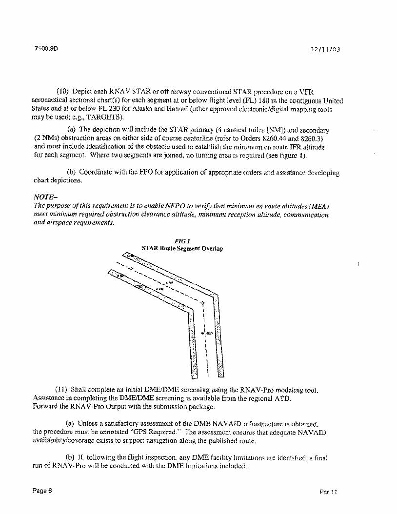
121103 71009D
(c) When icquired request Expanded Service Volume (ESV) through the ESV Management System (ESVMS) The ESVMS is accessible via the Spectrum Assignment and Engineering Division ASR-100
(12) In collaboration with the RNAV working group complete and forward the applicable forms environmental checklist ard annotated VFR sectional chart(s) to the ATD The applicable form for a conventional STAR is Form 7100-4 and the applicable forms for an RNAV STAR are Forms 7100-3 and 7100-4 (see appendixes 3 and 4)
(13) Conduct as a minimum a biennial review of existing STARs for accuracy simplicity standardization obsolescence and adherence to criteria in this order and the latest edition of Orders 82603 and 826019 Forwaid changes or updates to the ATD
(14) When it is necessary to cancel a STAR process appropriate Forms 7100-4 and 8260-2 After completion distribute to RAPT ATD National Flight Data Center (NFDC) NFPO and affected ATC facilities
c The RNAV Implementation Working Group shall
(1) Follow Guidelines for Implementing Terminal RNAV Procedures in Appendix 5
(2) Follow Guidelines for Design of Standard Terrmna Arrivals m Appendix 2
d The FPO shall
(1) Provide technical assistance on STAR development and review procedure desip for compliance with criteria
(2) Review STAR documentation The review shall include as a minimum the following
(a) Evaluation for impact by current or proposed obstacle evaluationsairport airspace analysis facilities and equipments national change proposals or other applicable projects
(b) Conduct database integrity checks (WP fix etc) to ensure accuracy of the data coordination of WPfix names and to confirm no other fixes or WPs are located at the same geographic location
(3) The FPO shall contact the submitting ATC facility to resolve any problems found during the review The working group and ATC shall be responsible for additional coordination of changes identified during the review process
(4) Facilitate discussion of the STAR at the RAFf
(5) Transmit the S TAR documentation to the NFPO
Par 11 Pago 7
710Q9D 121103
e The All Weather Office (AWO) shall
(1) Piovide technical assistance on STAR development
(2) Provide assistance in determining the equivalent level of safety required for any flight standards waivers needed
f The NFPO shall
(1) Review STAR documentation and conduct data integrity check for existing facilities (WP fix etc) against the data contained in the approved database for continuity This is to ensure accuracy of the data coordination of names and to eonOrm no other fixes or WPs are located at the same geographic location
(2) Review the STAR for MEA and bearingdistance between fixesWP
(3) After the package is complete forward STAR documentation to Flight Inspection Central Operations for coordination of the flight inspection
(4) Complete Form 8260-2 based on the submitted worksheets
(5) Forward documentation of flight inspection and original forms to the NFDC for further processing and a copy to the regional ATD Critical DME facilities as identified by fliglit inspection shall be annotated on the Form 7100 4 in block 15
g The NFDC shall
(1) Conduct a prepublication review of submitted forms to ensure compliance with applicable directives and resolve data conflicts form discrepancies etc with the NFPO and regional ATD
(2) Verify that WP names are not duplicated
(3) Assign an effective date and publish the STAR and associated fixesWP in the National Flight Data Digest (NEDD) authorizing charting agencies to publish the STAR
(4) File and maintain the original signed copy of the forms
(5) When a STAR or WP is cancelled emure names are made available for future use
h The NACO shall
(1) Advise the RAPT and ATD of any charting issues or publication delays
(2) Publish the STAR on the effective date assigned by NFDC
Page 8 Par 11
121103 71009D
12 ACCURACY VERIFICATION AND RESPONSIBILITIES Users of this order shall notify the NFDC flight service station or local air traffic unit for possible NOTAM action whenever errors are discovered in the NFDD or when reviewing a STAR
a STAR NOTAM Issuance
(1) Order 79302 prescribes procedures used to obtain formal and disseminate information on unanticipated or temporary changes to components of or hazards in the National Airspace System until the associated aeronautical charts aod related publications have been amended The NOTAM system should not be used to advertise data already published or charted
(2) When changes occur so rapidly that time does not permit issuance on a chart or in an appropriate pubication they are publicized as NOTAMs Originators of airmen information are expected to inform the NFDC in sufficient time before the effective dates of changes to permit publishing of aeronautical data on the various charts or in the appropriate publications
(3) Information pertaining to temporary changes in published STARs and profile descent procedures shall be submitted to the United States NOTAM Office (USNOF) for dissemination as NOTAM D
USD XKDCKX BOS SCUFF THREE ARRIVALRAALF TRANSITION DELETE SEGMENT FROM JFK VORDME TO RAALF INT CHANGE INITIAL ROUTING TO READ FROM OVER RAALF INT VIA ORW VORDME R-261 TO OKW VORDME REST OF ROU1E UNCHANGED
(4) Changes to STARs requiting immediate dissemination shall be originated by the affected ARTCC and submitted to the USNOF for issuance as a NOTAM D
b Permanent Changes Appropriate Forms 7100-4 and 7100-3 must be submitted to effect permanent charting changes NOTAMs on STARs will be carried on the system until published Upon formal publication of the amended STAR the facility that submitted any applicable NOTAMs shall ensure they are cancelled through the USNOF
13 MILITARY STARS Military STARs are developed and published in the same manner as civil STARs and shall comply with the criteria outlined in this order Miliary proponents are responsible for ensuring coordination with the RAPT and affected ATC facilities TheFAA will develop STARs at joint-usefalffieTtis I
David B Johnson Director of Air Traffic
Par 11 Page 9
121103 7100 9D Appendix 1
APPENDIX 1 ACRONYMS TERMS AND DEFINITIONS
AcronymTerra
AAO
APP CON
Area Navigation (RNAV)
ARTCC
ARTS
ATC
ATCT
ATD
ATIS
ATNS
AWO
AWOS
CP
Common Route
DF
DME
En Route Transition
FAA
Beltairiba
Adverse assumption obstacle - The means by which an obstruction is identified when no man-made obstruction is recorded or identified
Approach control
A method of navigation that permits aircraft operation on any desired flight path within the coverage of station-referenced navigation aids or within the limits of the capability of self-contained aidsf or a combination of these (See Pilot Controller Glossary)
Air route traffic control center
Automated Radar Terminal System
Air traffic control
Airport traffic control tower
Air Traffic Division
Automated Terminal information System
Air Traffic Noise Screen model
All weather operations
Automated Weather Observation System
Course to fix RNAV leg type
The segment of a STAR between the en route transition end point and the final point on a STAR
Direct to fix RNAV leg type
Distance measuring equipment
A published segment that connects one or more en route airwayjet route to the STAR
Federal Aviation Administration
Page 1
7100SD 121103 Appendix
Fix A generic term used to define a predetermined geographical position used for route definition A fix may he aground-based NAVAJD a waypoint or defined by reference to one or more radio NAVAIDs
FB Fly-by waypoint - Requires the use of turn aniicipiition to avoid overshoot of the next flight segment
FO Fly-over waypoint - Precludes any turn until the waypoint is overflown
and is followed by an intercept maneuver of the next flight segment
FMS Flight Management System
FPNM Feet per nautical mile
FPO Flight Procedures Office (An element of the National Fliglit
Procedures Office located at each FAA regional headquarters)
FSS Flight service station
GPS Global Positioning System
HCS Hos Computer System IF Path terminator denoting the initial fix of an RNAV route leg
See path and terminator
IFR Instrument flight rules
KIAS Knots indicated airspeed
KTS Knots Lead Operator An operator that has agreed to serve as the focal point for the development
of STARs at a specific airport The lead operator agrees to help develop the STAR and ensure fly-ability by all aircraft expected to use the STAR
Leg Type See path and terminator
I OA Letter of agreern ent
MEA Minimum en route IFR altitude
MSL Mean sea level
NACO National Aeronautical Charting Office
NAVAID Navigational aid
Page 2
123103
NEPA
NFDD
NFDC
NFPO
NOTAM
NM
NRP
Path and Terminator
Proponent
RAPT
RNP
Significant Benefits
SOP
STAR
TARGETS
TERPS
TF
710Q9D Appendix 1
National Environmental Policy Act
National Flight Data Digest
National Fliglit Data Center
National Flight Procedures Office
Notice to airmen
Nautical mile
North American Route Program
An ARINO 424 term that is defined as a set of two alphabetic characters The first identifies the type of flight path and the second indicates where the route leg terminates eg TF DF CF VM
The originator of a STAR requirement This may include an individual user group ATC NFPO or other appropriate government agency
Regional Airspace Procedures Team
Required navigation performance A statement of the navigational performance accuracy necessary for operation within defined airspace
Standard instrument approach procedure
Tangible or intangible advantages resulting from the implementation of a STAR such as fuel savings from reduced flight tracks and time reduced mterintra facility coordination reduced communication between ATC and pilots increased flexibility of airspace management and sectorizalion due to more predictable ground tracks or other similar benefits to users or ATC
Standard operating procedures
Standard Terminal Arrival - A preplanned instrumentfliglit rule (IFR) air traffic control arrival procedure published for pilot use in graphic form STARs provide transition from the en route structure to an outer fix or an instrument approach fixarrival waypoint in the terminal area
Terminal Area Route Generation Evaluation Traffic Simulation tool
1 erniinal instrument procedures
Track to fix
Page3
71009D
Appendsx 1 3 2 1103
TRACON Terrainal radar approach control facility
Transitions See common route and en loute transition VFR Visual flight rales
VM Heading to a manual termination (sped fled as a heading until a manual termination)
WP Waypoint - A predetermined geographical position used for routeinstrument approach definition progress reports pubhshed WR routes visual reporting points or points for transitioning andor circumnavigating controlled andor special use airspace that is defined relative to a VORTAC station or in termamp uflatitudelongitiide coordinates
Page A
121103 71039D Appendix 2
APPENDIX 2 GUIDELINES FOR DESIGN OF STANDARD TERMINAL ARRIVALS
1 GENERAL Safety is a primary concern in the design of Standard Terminal Arrival (STAR) routes A STAR will not be established solely for the purpose of noise abatement but existing noise abatement procedures should be considered in the STARS design In addition all procedures shall be evaluated for possible environmental effects in accordance with Order 10501 Policies and Procedures for Considering Environmental Impacts to ensure that the requirements oftbe National Environmental Policy Act have been met An environmental checklist and the Air Traffic Noise Screening model shall be used for this purpose Close coordination is required with the terminal procedures specialist and regional air traffic environmental specialist to ensure compliance with applicable environmental laws regulations and policies
a STARs shall
(1) Be simple and easily understood
(2) Commence at an en route fix eg navigational aid (NAVAJD) intersection distance measuring equipment (DME) fix or waypoint
(3) Be compatible with local air traffic control (ATC) standard operating procedures (SOP) and traffic flow management procedures
(4) Include in the graphic depiction holding patterns referenced in the narrative of the STAR
(5) Be designed to Level 2 criteria as defined in Order 826044 Civil Utilization of Area Navigation (RNAV) Departure Procedures (RNAV only)
(6) Shall not require automated vertical navigation
(7) Depict a minimum en route altitude (MEA) for each segment of an arrival m accordance with Order 82603 United States Standard for Terminal Instrument Procedures The MEA of each segment shall not be higher than the preceding segment In mountainous areas obstacle clearance may he reduced from 2000 feet to 1000 feet when necessary to achieve compatibility with the associated instrument appioach procedures (TAP) with approval from the National Flight Procedures Office
(8) Terminate at an initial approach fix for a standard instrument approach procedure (SIAP) or at a point in space defined by a fix or waypoint An RNAV STAR shall terminate at a point from which radar vectors may be initiated For airports served by a radar approach control terminate at a point within the terminal airspace
(9) When terminating at a point in space that is not associated with an f AP be charted with air traffic vectors and lost communication instructions if lost communications procedures differ from 14 Code of Federal Regulations (CFR) 91185
Paqo 1
71009D Appendix 2 121103
(10) Not combine conventional and RNAV STARs on the same chart
(11) Use procedural data notes when limitations are necessary eg services to be provided in conjunction with the procedure designated aircraft equipment eapabilitys etc Do not include items of an ATC clearance in notes
ExampleshyRADAR REQUIRED or FOR USE BYE t A3 andR (RNP-20) EQUIPPED AIRCRAFT ONLY
b STARs should
(1) Be developed to accommodate as many different types of aircraft as possible
(2) Provide for a significant usersystem benefit
(3) Reduce pilotcontroller communications and workload
(4) Use only the minimum number offixeswaypomts turns and speed or altitude changes to depict the route
(5) Avoid the use of DME arcs
(6) Establish crossing altitudes for traffic separation andor obstacle clearance
c STARs may
(1) Serve multiple airports
(2) Be designed to overlay the vector procedure from an en route fix to a point in space orSIAPfix
2 RNAV STARs This section describes the elements specific to RNAV STAR procedures The design of an RNAV STAR may include two segment types en route transitions and a single common route (see figure 1) These segments will be depicted with poundy-by (FB)fly-over (FO) waypoints (that may have associated altitude and speed requirements) and leg types
Page 2
H009D 121103 Appends 2
FIG J
RNAV STAR Example
PEPPR
SAIL
RUNNR jSPSEJBu]
0ANCR Vectors to TABLE OME RNAV ARRIVAL Final (TBLT8L1)
RNAlTifA^WrTH THREE EN ROtTE n
TRANSITIONS AMD VECTORS TO FINAL
a Waypoints An RNAV STAR must be designed using waypoints This provision does not preclude the use of an existing NAVAJDfix FB waypoints shall be used except the last waypoint shall be coded as aFO waypoint
(1) Design STARs using the fewest number of waypoints
(2) Names assigned ibi waypoints shall consist of a singlefive-letter pronounceable name
(3) Use existing NAVATDsfixes or waypoints whenever possible Waypoints that are co-located with existmg NAVATDs shall use the NA VATD three-letter location identifier
(4) Waypoints may be assigned crossing altitudes and speeds to optimize the descent and deceleration profiles Waypoint crossing assignment types shall be defined as at at or above at or below or expect
(a) Limit the number of altitude and speed requirements to the minimum necessary Altitude assignments shall not include both at or above and at or below in the same procedure Expect altitudes or airspeeds will not be coded into an aircraft navigation database
Page 3
71009D Appendix 2 12 11 03
(b) Avoid the use of multiple altitude or speed restrictions at same waypoint egbdquo cross XRAY at 9000 feet when Runway 27 in use but cross XRAY at 11000 feet when Runway 9 is active When multiple restrictions cannot be avoided at a particular waypoint use expect altitudes oi speeds This does not prohibit the combined use of a single altitude and a single speed assignment for a waypoint
b Leg type (path terminator) The following table shows permissible leg types for use with RNAV STARs (refer to Order 826044 for leg-type definitions and examples)
TBLl Leg-Type Example
(From Waypoint Via (leg type) To Waypoint lt FB TFCF FBFO Irp2 T X C F T D F FBFO
VM3jFO wsiisiSiiiiHi
(1) Track to fix (TF) is the preferred leg type from an FB to a FBFO
(2) An IF is used to designate the first waypoint of a STAR transition
(3) A heading until a manual termination (VM) leg may be used only after the last waypoint A VM leg shall be atabove the minimum vectoring altitude
c Leg Length
(1) Use the longest legs possible The designer must consider speed and course changes when determining minimum kg length (refer to Order 826044 for specific minima)
(2) The maximum leg length for straight-line paths is 260 miles to ensure the geodesic path does not exceed the protected airspace for a great circle path
d Turn Angle
(1) For a track change at a FB waypoint below flight level (FL) 195 avoid turn angles of greater than 120 degrees
(2) For a track change at a FB waypoint at or above FL 195 avoid turn angles of greater than 70 degrees
c Descent Gradients and Deceleration Segments
(1) STAR procedures should be designed to standardize descents from the high-altitude en route stratum down to the terminal environment
Page laquo
F1C09D 121103 Appendix 2
(2) A descent gradient of 318 feet per nautical mile (FPNM) (a 3-degree vertical path angle [VPA]) should be used from the en route environment to 10000 feet mean sea level (MSL) Below 10000 feet MSL the descent gradient should not exceed 330 FPNM (a 31-degree VPA)
Note-Based on ATC SOPs RNA V STARs may require descent gradients that exceed the 330 FPNM
A descent gradient greater than 330 FPNM may require manual speed intervention by the pilot and deceleration segments may need to he increased to compensate
(3) The STAR designer shall allow for a deceleration at any waypoint that has a speed restriction The operational requirement of affected operators should be considered As a general deceleration guideline the leg distance between the waypoints should be increased at least 1 nautical mile (NM) per 10 knots (KTS) of deceleration required
Example-An RNAV STAR begins at waypoint ALPHA at 17000feet MSL and 310 KTS This STAR requires the aircraft to descend to and cross waypoint BRAVO at 9000feet MSL at 240 KTS The minimum leg length between ALPHA and BRAVO would be computed as follows
(17000 - 9000) + 318 = Minimum leg length using a 3-degree descent gradient 8000 +318^ 25157NM
plus
(310 - 240 + 10 - Deceleration segment 70 + 10-7NM 7 = 32J57 NM (round to 3216)
(4) STAR design should account for the deceleration necessary to slow the aircraft to 250 KTS at 10000 feet MSL If the STAR ends within 20 miles of a landing runway the STAR should also provide a deceleration segment that allows for a speed reduction from 250 KTS to 200 KTS
f Levels of criteria (For RNAV STAR development use Level 2 criteria only)
(1) Level 2 criteria correspond to a level of aircraft performance The following RNAV equipment suffixes defined in the Aeronautical Information Manual indicate aircraft that are capable of Level 2 STARs
(a) E - Dual FMS equipped aircraft
(b) F - Single FMS equipped aircraft without a moving map display
(c) G - Global Positioning System equipped aircraft
Page 5
71O09D Appendix 2 321103
(d) R - (RNP 2 0) Aircraft approved For required na igation performance (RNP) opcraiions of RNP 2 0 or less
(e) Include the standard note For use by III Fraquo G or R (RNP 20) equipped aircraft only in the remarks section of form 7100-4 STAR - Standard Terminal Arrival
g RNP Reserved
h STAR Naming and Computer Code Identification
() A STAR shall be named to correspond with a NAVAID fix or waypoint identifier on the common route normally where the common route begins An RNAV STAR will include the term RNAV in the name eg TOEZZ ONE RNAV ARRIVAL
(2) STARs shall not be given a name that implies a direction e g north east south west etc
(3) STAR names shall not be duplicated STAR designers should also avoid the use of similar sounding STAR names
(4) Number each original STAR -ONE eg DLBRT ONE RNAV ARRIVAL Number subsequent revisions m numerical sequence through NIN E and then restart at ONE Renumber STARs whenever a revised FAA 7100 series form is required
(5) The STAR computer code will be assigned by using the NAVAIDfix or waypomi identifier where the STAR common route begins followed by a dot then the identifier associated with the name of the procedure followed by a revision numeral (1-9)
(6) En route transitions also require a computer code En route transitions are assigned by using the NAVAID fix or waypoint identifier name where the en route transition begins separated by a dot followed by the identifiername of the STAR and suffixed with a numeral (1 -9) The STAR naming and computer-coding conventions are illustrated in figures I and 2
Page 6
7100 9D 121103 Appendix
FIG 2 RNAV STAR Example
SALLT
|SALLT 5MJLT1j
RUNMR
DANCR SALLT ONE RNAV ARRIVAL gt (vectors to (SALITSUT1)
l F i n a l fRNAV STAR WITH HO TRANSITIONS AND VECTORS TO FINftL
i Fix Waypoint Holding Pattern and Communication (CHARTING) Information that is charted in graphic form should not be duplicated in a textual description on the chart
(1) Fixes waypoints and associated holding patterns should be published on en route low-altitude and high-altitude charts when they are used for en route ATC
(2) Fixes waypoints and holding patterns should be published on arrival charts when they are used for the contiol of arrival traffic into a specified area
(3) A published holding pattern depicted at a fix or waypoint on a lowliigh altitude en route chart or area chart shall be published on any arrival chart that depicts the same fix or waypoint
(4) Refer to Order 8260 19 Flight Procedures and Airspace for use of magnetic variance in the development of holding patterns and point-to-point navigation for RNAV versus conventional NAVAJDs
(5) For RNAV STARs that terminate at a point in space annotate on the chart that radar vectors will be provided eg expect radar vectors to final and annotate the chart with the lost communication procedure if lost communications procedures differ from 14 CFR 91 185
Pacse
71009D Appencix 2 121103
(6) Chart at least one very high frequency (VIIF) one ultra highfrequency (U1IF) (where available) and the Automated Terminal Information System at each airport served by the STAR
(7) The maximum number of airportfrequencies that may be charted shall not exceed one VHF and one UHF (where available) for tower and ground control
(8) Include one VI If and one UITF air route traffic control center frequency only when there is no terminal facility involved
(9) Control frequencies shall not be included in the arrival text
Pages
7100SD 121103 idlx 3
APPENDIX 3 INSTRUCTIONS FOR COMPLETING RNAV STAR FORM 7100-3
BLOCK L HXNAVAIP Enter the name of the fix or navigational aid (NAVAID) in one of the following two formats (1) five-letter pronounceable name and type or (2) three letter facility identification plus facility type egTBL VOR SPICK WP
BLOCK2 LATLONG Enter the north latitude followed by the west longitude (separated by a ) associated with the item listed in block 1 In degrees minutes seconds and hundredths of a second eg 40190022078503021
BLOCK 3 C (chart) Enter a Y (yes) i the item in block 1 is to he charted Enter an N (no) if charting is not required
Note-All fixes or NAVAIDs requiring a change in altitude speed or direction ((heading) require charting
BLOCK 4 FLY-BYFLY-OVER Enter 4TB to indicate a fly by waypoint or TO to indicate a fly-over waypoint
BLOCKS LEG TYPE Enter the two-letter leg-type code
BLOCK 6 TC (true course) Enter the true course to the nearest hundredth of a degree eg 16412
BLOCK 7 DIST (distance) Enter the distance to the nearest hundredth of a nautical mile eg 2464
BLOCKS ALTITUDE Enter altitude rounded to the nearest 100 lect or flight levels (FL) above FL 180 where necessary for traffic flow requirements and vertical descent profile Label each altitudeFL enteied with the appropriate indicator
BLOCK SPEED Enter knots indicated airspeed where necessary for procedure containment or traffic flow requirements Label each speed restriction with the appropriate indicator
TBLI Altitude Indicator
^^^m^f(M^^miiamp^ampmtfflm At or Above +8000
At (blank) 6000 At or Below -5000
Page 1
71009D Appendix 3 12110
TBI 2 Speed Indicator
MMim^m PljjfriftCII gg| At or Above +230
(blank) 240 At or Below -220
BLOCK 10 REMARKS Enter the en route transition computer code (see Appendix 2) and any other pertinent information that would clarify the reason for a data entry eg airspeed restriction required for tuni radius Enter expect altitudes and airspeeds in this block
BLOCK 1L ARRIVAL NAME Enter name of Standard Terminal Arrival (STAR) route (see Appendix 2)
Exampleshy
TINKR THREE RNAV ARRIVAL is entered as T1NKR RNAV
BLOCK 12 NUMBER Enter STAR revision number (see Appendix 2) eg EIGHT
BLOCK 13 STAR COMPUTER CODE Enter computer identification code (see Appendix 2) BLOCK 14 SUPERSEDED NR STAR revision number superseded by this STAR If original insert none
BLOCK 15 DATED Published or revision date of superseded STAR eg 17 NOV 02
BLOCK 16 EFFECTIVE DATE Completed by the National Flight Data Center
Page 2
US Department of Transportation RMAV STAR (Data Record) Federal Aiatioa Administration
(1) FIXMAVAID
En Route Transitions PEPPR WP
TBL VOR
SALLT WP
TBL VOR
SPICE WP
TBL VOR~
Common Route TBL VOR
I RUMNR WP
j DANCRWP
mdash1
(111Arrival NameTABLE RNAV
(2) LATLONG
40001644 077403926 39244402 0772230 49
39575908 076552780
39244402 077223049
39290100 07634350039244402 077223049
39244402 077223049 39192758 077291833 39112722 077292910
_
_
j j
(3) C
I Y
Y
Y
Y j
lt
Y _ _
Y
mdash
Y
Y
mdash
112
Nu mber laquoME
(4) (5) m FOFB LEG TC
IF
FB TF 15838
r IF
FB TF 21229
IF
bdquo 2 m _FB TF
IF
FB 22605
P Q -fp leToo
_ mdash- mdash - mdash mdash
mdash mdash
(13) STAR Compu ter Code
T Q I L1 1 tJL I B
(7) (8) DIST ALTiTUDE
3817
3924
~37 37
mdash shy- shy
i
745
eoo 6000
_ trade ~ mdash
mdash
(14| Superseded Nr
none
m SPEED
-250
_ _ u
-250
mdash
250
i
i
(15) Dated
(10) REMARKS
j
PEPPRTBL1
Expect 10000
SALLTTBL1 J
Expect 10000
SPICETBL1
Expect 10000
Fxpect10000
(16) Effective
Date
1J1
9 -4
bulla o ns o a lt fr
FAA Forra 7100-3 (902)
o | i n o 71009D
APPENDIX 4 INSTRUCTIONS FOR COMPLETING FAA FORM 7100-4
BLOCK l a TRANSITION NAMMS) Enter the name of each en route transition according lo the name of the fix or navigational aid (NAVAID) where the en route transition(s) begins eg for a transition starting at the TNP VOR enter Twenty Nine Palms as the transition name Do not include the word transition
BLOCK lb TRANSITION COMPUTER CODES Enter computer code (see Appendix 2)
BLOCK 1c FROM FIXNAVA1D Enter the name and type offixNA VAID where each en route transition begins Use the following to identify type WP TNT VORTAC etc eg GFE VORTAC GOINN INT UbTIT WP
BLOCK Id TO FIXMAVAID Enter the name(s) and type(s) of all fixNAVAiD(s) that describe the en route transition after the first point to and including the common point egf GFE VORTAC GOINN INT GETIT WP
Note-If a transition has multiple segments use one line for each segment
BLOCK l a MAG COURSEDISTANCE Enter the magnetic course and distance for each transition segment Specify the magnetic course to the hundredth of a degree eg 35424 and distance to the hundredth of a mile eg 7243 The National Aeronautical Charting Office (NACO) will round entries to the nearest whole degree for publication
BLOCK If MEA Enter the minimum en route altitude (MEA) along each en route segment En route transitions sharing a common segment should have the same MEA If it is the intention to have different MEAs on a common segment note this in block 14 Remarks
BLOCK lg MOCA Enter the minimum obstruction clearance altitude (MOCA) along the route
BLOCK lh MAA Enter the maximum authorized altitude (MAA) along each en route transition
BLOCK 11 CROSSING ALTITUDEFIXES Enter altitude rounded up to the nearest 100 feet or flight levels (FL) above FL 180 where necessary for traffic flow requirements and vertical descent profile (see Appendix 3)
BLOCK 2 ARRIVAL ROUTE PESCRHTION Provide a textual description of the Standard Terminal Arrival (STAR) route from the common route starling point to the ending point of the STAR Document all courses headings tracks and distances to the nearest hundredth unit of measurement In parenthesis list the MEA andor MOCA foi each segment as required eg MEA 5000 MOCA 2500
Note-Block 2 entries will he published verbatim on the NACO chart with the exception of courses headings and tracks which will he rounded by NACO to the nearest whole degree
Pagel
71009D 121103 Appendix 4
Area navigation (RNAV) STARs The- textual description of an RNAV STAR requires specific narrative wording to match the leg type information depicted on associated Form 7100-3 RNAV STAR (Data Record) (see table 1 for required wording) Ensure courses tracks headings and distances entered on Form 7100-4 STAR - Standard Terminal Arrival match the equivalent true values and distances entered on Form 7100-3 In addition turn directions shall be specified as either left or right as follows
Direct to fix (DF) legs All course changes
Course to fix (CF) and track to fix (TF) legs All course changes exceeding 90 degrees
Note-Ifthe STAR is or becomes a series of consecutive TF legs with turns less than or equal to 90 degrees a complete textual description from that point is not necessary State thence as depicted
TBL1 Leg Type Wording and Required Information
Ugyffij mmmmmmmmmm TF DF CF VM
Track Direct Course Heading
Coursediamptanceium direction Turn direction distance
Course distance turn direction Heading
Example-A TF leg followed by a heading until a manual termination (VM) kg via 07011 track to TALKN WP then via 09012 heading Expect radar vectors
A CF leg followed by a DF leg via 32022 course to cross WALKN WP atabove 10000feet then right tum direct TRYNN WP
Consecutive TF legs via 27011 track to DRYVN thence as depicted toFLYYN WP
BLOCK 3 PROCEDURAL DATA NOTES Enter any information that will appear in note form on the published chart eg distance measuring equipment (DME) required RADAR required Also list any altitudespeed restrictions not associated with a particular waypoint (WP)fix Notes should be clear and easily understood by pilots using the procedure For landing flow vise landing direction not traffic flow direction
For RNAV STARs procedures intended for use by IE F or R regardless of required navigation performance (RNP) accuracy must include the note GPS required unless a satisfactory DMFDME assessment n completed and documented in block 15
BLOCK 4 FIXES ANDOR HOLDING PATTERNS Enter those fixes or NAVADDs for which holding is required and enter the applicable holding instructions Ensure the accompanying Form 8260-2 Data Worksheet contains the same charting instructions for holding patterns supporting the STAR
Page 2
71009D 12 11 03 Appendix 4
BLOCK 5 COMMUNICATION Enter the name all of radio communications to be charted eg ATIS AWOS API CON Specify the frequencies only if different than what is currently published for the facility
BLOCK ltbull ARRIVAL NAME Enter name of STAR (see Appendix 2) eg CHARLOTTE EIGHT ARRIVAL is entered as CHARLOTTE TINKR THREE RNAV ARRIVAL is entered as
UNKRRNAV
BLOCK 7 NUMBER Enter STAR revision number (see Appendix 2) eg EIGHT
BLOCK g STAR COMUTKIjCOPE Enter computer identification code (see appendix 2) BLOCK SUPERSEDED NR STAR revision number superseded by this STAR If original cuter none
BLOCK 10 DATED Published or revision date of superseded STAR eg 17 NOV 02
BLOCK 11 EFFECTIVE DATE Completed by the National flight Date Center
BLOCK 12 AIRPORTS SERVED Enter all airports served by the STAR List the csty and two-letter state code for each airport listed
BLOCK 13 LOST COMMUNICATION PROCEDURE Enter lost communications procedure if required to be included in the textual description Leave blank when procedures are the same as 14 Code of Federal Regulations 9U85-
BLOCK 14 REMARKS List informationdata that is not to be charted eg administrative data or notes for controller information (requested by air traffic control) 1 bese items will not be seen in the National Flight Data Digest
BLOCK 15 ADDITIONAL FLIGHT DATA List any additional charting instructions items essential to clarify charting or information a specialist has determined needs charting as other than a note Data may include terrain features additional airports Special Use Airspace or landing obstacles
For RNAV STARs place the reference (arrival airport) magnetic variation of record used to develop the STAR in this block eg REFERENCE MAG VAR KNTW 10W00
The National Flight Procedures Office will enter one of the following after completion of the flight inspection
a DMEDME Assessment SAT (RNP 20) indicates a successful assessment to the RNP value specified
b DMEDME Assessment- DME limitations identifies specific DME facilities with limitations
DMEDME Assessment- I INS AT indicates an unsuccessful assessment to RNP 20 If the DMEDME assessment indicates UNS AT che note GPS required must be entered in block 3
Page 3
c
71009D _ Appends 4 i i l l O J
Note-The DMEDME assessment process is covered in separate guidance
BLOCK 16 CONTINUATION Use this area of the sheet lo complete any data block from previous pages Indicate block number and title being continued
BLOCK 17 CHANGES List changes relating lo data entries
BLOCK 18 REASONS List reasons for changes identified m block 17
BLOCK 19 GRAPHIC DEPICITON Include a graphic depiction of the STAR Identify on the depiction the magnetic and true course between fixes intersections waypoints or very high-frequency omnidirectional ranges (VOR) and list any required altitudes and speeds
Page^
^ Beormgs poundamp3e1flsectpound esamprses ard radiak amp^ ljstssect lsgt II e
JS DcpjrSflmani of ^Twsportatiot f edersl Avail j n Atrniiiiilralscii STAR-Standard Terminal Arrival 3 AluLisss a nrp iu wri jfcli^o^s unices irir-wampi $
li Transjtipji RouJfisJr3CraquohIc Depiction O n M _ _ ^ _ _ _
a) Transition ltbj ransttior | (c) From RNAV WP j (d)TtaRMAV WPNamo s Computer Codes J FWNAVAID RxNAVAIDbdquo i bdquo mdash bdquo
| M
M
bdquo
M T O ^
bdquo _ bdquo
r n l ] r n w a 8 W P CourseDistance Jf) MFA (g) MOCA
l s fh) MAA
l ^ r t ^ S
Altitudesfixes
O
pfcppfi PES-VKJBLI Pl i-^K WP TBLVOR 168 38381 FL210
SAI LT SALLT TBLt S A t i r w p WL VOR 222 283324 pound003 FL2C
SMCF SPICE T8L1 SP CB Vilaquo 8 VOR 263683737 8000 FL210
(2) Arrival Route Description f rom TBL VOR via 235 05 track to RUNNR WP (hence as depleted to cross DANCR WP al 6000 (MFA 5000 Expact radar vectors to final approach course
(3| Procedural Data NotesCross DANCR at 6003
Radar reewnsd Th s STAR applicable to iurampojs aircrat only Expect o cross TBL at 10000 Cross TBL at or below 50 KT S
(4) Fixes andor Holding Patterns Cha^t LA~7LONG coordinates tor TABLb
(5) Communicationsshy
6 Arrival Name TABLE RNAV
NWT ARRvAL ATLgt FREQ 11b 71348 NCWTOWN CENTER FREQ 13252 NbWTOWN APdegROACH CONTROt
7 Number
ONE (8) STAR Computer C o f (9) Superseded Mr j 10) Dated
TBLTBL1 NONE DDMOYR
1267123 9S
(115 Effective Date
SVaSM
mdash o o
bull
FAA Form 7100-4(702)
(12) Airports Served 00 Airport Name Newtown international c Airport Name
Airport Name Airport Name Airport Marne Airport Maotts
(13) Lost Communications Procedure
(14) Remarks- RHFHRENCH MAG VAR KNTW 10W00
(15) Additional Flight Data
Cily$tate Newtown NJ CityState CityState CityState CityState CttyState
-0 copy
8stgt o iomdash - mdash mdash - shyis shy
_ mdash bdquo mdash
(6) Arrival Name (7) Number (8) STAR Computer Code |9 Superseded Nr (10gt Dated (11gt Effective Date | ~gt
TABLE RNAV ONE TBLT8L1 NONE DDMOYR
FAA Form 7190-4 (702)
i-1
(16) Continuation
o us
(17) Changes
(18) Reasons for Changes
Developed By
L Name (Typed and Signed) Title and Organization Example John Smith
Support Specialist Washington Center
DATE
Approved NFPO
TO ra ATD ltx) O
rs o a bull
(6) Arrival Name (7) Number (8) STAR Computer Code (9) Superseded Mr 10 Dated (11) Effective DateTABLE RNAV ONE TBLTBL1 NONE DDMOYR DOMOYR
FAA Fnriit 7100-4 (702)
i
araquo -vi (19) Graphic Depiction gtT3 raquo -
ns o raquo op gtPEPPR CO A u S
SALLT
TBL Expect to cross I at 10000 Cross at or telwv 2poundOkts
SPICE RUNNR
FAA Form 7100-4 (702)
7100 9D 1 2 1 1 0 3 Append 5
APPKNOJX 5 GUIDELINES TOR IVJPLKMEN ItSG TERMINAL RNAV PROCEDURES
IMTRODUCriCKN
This document is a standardized systematic process for the development of terminal area navigation (RNAV) amval and departure pioceduies (DP) This process is designed to be used by members of the RNAV Implementation Working Group (see table i) with the goal to publish an RNAV arrival or DP The guidance in this document incoiporates past lessons learned and references material used to accomplish the project objectives The process is known as Guidelines fot Implementing Terminal RNAV Procedures (guidelines) and must be used in conjunction with Order 826043 Flight Procedures Management Program and other applicable Federal Aviation Administration (FAA) orders governing terminal RNAV procedure design
The guideline provide the RNAV Implementation Working Group with a tracking mechanism to expedite the development review and implementation of a terminal RNAV procedure This is accomplished by providing instructions that separate design and implementation into manageable items that arc mapped as closely as possible to the anticipated sequential order of RNAV procedure development However due to the dynamic nature of RNAV piocedure development guideline items may be completed concurrently or in an order different than that presented in the guidelines Additionally if during the development of a procedure changes to the design arc required the working group must revisil all applicable items in the guidelines to ensure all changes have been addressed
It is important to remember that during the project duration maintaining a committed working group is critical lo the projects success A key element of this collaborative process is the sharing of information The guidelines play a significant role in this process by providing a medium by which information regarding resource requirements and specific user roles may be identified and shared among team members
GUIDELINE ITEMS
I Kickoff Meeting
I his item describes the activities involved in plaiuimg conducting and administering an RNAV Implementation Working Group kickoff meeting which includes preliminary design of an RNAV procedure Additionally this item provides guidance on managing regularly scheduled working group conference calls (telcons)
a Project Facilitator
(I) Prcmeetmg requirements
(a) Schedule a kickoff meeting thai brings together the members of the working group (see table 1)
Page 1
71009D Appendix 5 121103
(b) Determine need for working group participation by individualsorganizations not listed in table 1 Arrange for their participation as necessary
(c) Advise RNAV procedure proponent(s) to be prepared to present their proposals
(d) Advise Terminal Area Route Generation Evaluation and Traffic Simulation (TARGETS) tool operator to complete guideline item 2 Adaption of TARGETS Adapt TARGETS and be prepared to present a demonstration of TARGETS as needed
(2) Initial meeting
(a) Introduce the Guidelines for Implementing Terminal RNAV Procedures to include the participants roles and responsibilities from table 1
(b) Provide an overview of any ongoing RNAV development projects at the air traffic control (ATC) facility or elsewhere in the region
(c) Develop a mission statement that provides clear direction for the working group The mission statement should identify the projects goal
Example-Define develop and implement RNAV procedures and profiles in the New York Terminal Radar Approach Control (TRACON) facility airspace to increase safety reduce communications improve userprovider efficiencies and improve air transportation sendee to the traveling public at the John F Kennedy International Airport
(3) Administrative activities
(a) Develop a point of contact list using Fonn 4 Working Group Contact List
(b) In coordination with the Flight Procedures Office (FPO) establish a schedule for guideline item completion that meets the publication dale TARGETS contains a Microsoft project template of critical path and average timeline schedule for each item
(c) Establish telcon schedule
Note-After the kickoff meeting telcons are the primary metliod by which the working group meets They are used to coordinate activities ensure timely completion of project items refine issues verify completion of required work and to truck remaining items and critical schedule dependencies
(d) Identify the organization (usually the FAA regional office) responsible for establishing the telcon bridge Obtain the telephone number and access code
Page 2
121103 7 1 0 0 9 D
Appendix 5 (4) Post meeting requirements
Create and begm regular (as needed) distribution of project documentation to the working group This will generally consist of some or all of the following
(a) An e-mail documenting meeting or telcon attendees minutes of the previous meeting or telcon and the next meeting or telcon agenda
(b) An updated list o faction items and the guideline index
(c) The TARGETS RNAV distribution package which includes a PowerPoint diagram ot the procedure and a waypoint data table depictmg the latitudelongitude coordinates FAA leg types and when assigned altitudespeed for each waypoint
(d) Additional documentation as needed
Note-It is imperative that individuals with decisionmaking authority participate m teicons In certain cases it may be pr udent to cam el a telcon or even terminate a telcon in progress when key participants are not available This will reduce the need for post telcon coordination assist in consensus building and help to ensure all aspects of important issues arefully addressed
b TARGETS Operator
(1) Conduct demonstration of TARGETS if necessarj
(2) Operate TARGETS during preliminary and subsequent orocedure design activities
2 Adaptation of TARGETS
This item describes the activities required to prepare TARGETS for the site-specific procedute design Tire 1ARGEFS operator shall acquire and install the following data elements mto TARGETS
a Navigation Data
Provided by the National Flight Data Center (NFDC) on CD-ROM
b Video Maps
Digital maps provided m digital DAT format by the National Aeronautical Charting Office (NACO)
Page 3
71009D Appendix 5 121103
c Automated Radar Terminal Systems (ARTS)Standard Terminal Automation Replacement System (STARS) Data
ATC facility management provides ARTSSTARS data This data is used in TARGETS to confirm existing traffic flows This daia may also bs used in the construction of scenarios for controller familiarization and evaluation Sufficient track data should be installed to adequately characterize the traffic flows for the particular airportrunway configuration of interest
d Aircraft Performance Data
TARGETS is preconfigured with a set of generic aircraft performance that is used lor the flyability evaluations In addition specific aircraft performance data can be entered in TARGETS
3 Reserve Waypoiot Names
This item describes the steps necessary to reserve waypoint names and to reduce the possibility of duplicated name assignments
a ATC Facility Management
(1) Coordinate with the appropriate air route traffic control center (ARTCC) to reserve a block of waypoint names for the project
(2) Verify with the NFDC that the names have not already been used
b TARGETS Operator
Enter waypoint names into TARGETS
c Lead Operator
Verify with charting and navigation database suppher(s) that the names have not already been used
4 Design of Procedure
The item provides guidance for designing the procedure However it is imperative thai procedure designers consult the most current edition of the appropriate references before and during the design process
a ATC Facility Management
(1) Design considerations
Pa goshy
71009D 1 2 1 1 0 3
Appendix 5
(a) Follow the design guidance hsted in the following applicable FAA orders Order 826044 Civil Utilization of RNAV Departure Procedures Order 8260 46 Departure Procedure Program andor Order 71 KJy Standard Terminal Arrival when defining the procedure Additional guidance can be obtained from the regional project facilitator or the Regional Airspace Procedures Team (RAPT)
(b) Assign procedure and waypoint names in accordance with the naming conventions outlined m the applicable FAA order
(c) The procedure must pass a TARGETS flyability evaluation and comply with minimum segment length requirements If unable to comply coordination with the FPO is necessary
(2) Air traffic considerations
(a) Ensure all waypoints that are located near airspace boundaries are positioned to comply with required separation standards Waypoints located less than 40 miles from the radar antenna must be at least 35 nautical miles (NM) from the boundary and greater than 40 miles from the antenna must be at least 4 5 NMs
(b) Consider possible traffic conflicts eg piggybacks letters of agreement [LOAj routings other airport flows etc
(e) For departures where required ensure an interim altitude is given for each runwaytransition in the chart narrative eg MAINTAIN 3000 feet expect filed altitude 10 minutes after departure
(d) For procedures designed to overlay historical trackspattcrm cheek against the plotted ARTSSTARS data to verify that the procedures lateral track complies with current traffic flows
(e) Controller simulations using the TARGETS simulation (unction may be used to identify potential traffic conflicts or design issues See item 5 Simulator Evaluations
(f) Consider lost communication procedures and phraseology necessary for the procedure
(g) Solicit feedback from facility controllers on the procedures design and potential operational impacts
b FPO Verify Airport Magnetic Variation Being Used for Project
c TARGETS Operator
(1) Prior lo submitting the documentation to the FPO apply ATC facility selected names to all waypoints associated with the procedure
Pago 5
7100 9D Appendix 5 1 2 1 1 0 3
(2) Ensure that the TARGETS has tli2 correct magnetic variation for the airpon
(3) Build proposed RNAV procedure in TARGETS and perform flyability evaluation^)
(4) Create and distribute the TARGETS RNAV distribution package o the project facilitator for subsequent distribution to the remainder of the working group
d Lead Operator
(1) Obtain input on procedure design and navigation coding from a charting and database supplier
(2) Advise the principal operating inspector (POI) of the procedure design
(3) Identify and address flight deck human factors (TIF) issues Consider the impact of lateral navigation (LNAV) and veitical navigation (VNAV) procedure components on a vanety of aircraft con figurations
(4) For DPs coordinate with local air traffic management to identify and create runway position updating quick align (QA) waypoints Coordinate QA waypoint information with the regional 520amp530s Advise charting and database supplier for updates
5 Simulator Evaluations
This item provides guidance for simulator evaluations The purpose of aircraft simulator evaluations is to identify and resolve navigation database FAA leg type autoflight capabilities and HFs issues The purpose of ATC facility simulation is to identify and revive communication or operational impacts Simulator evaluations are not retmired but are strongly recommended They may occur anytime and should be repeated as necessary
a All Participants
Identify any special test conditions based on the procedures design or prevailing operating conditions that the lead operator should simulate e g if the first leg of the procedure is a heading leg the working group may want to simulate crosswind conditions during takeoff
b Lead Operator
(1) Obtain a database with coded procedure
(2) Evaluate the procedure in the simulator Alert the working group if it is necessary to evaluate the procedure in a simulator type not available to the lead operator
(3) Complete the output requirements for aircraft simulations Torm-5 RNAV Flight Simulator Worksheet and distribute the results to the working group
Page 6
71009D
121103 Appendix 5
(4) Report flyabihty or operational issues to the working group
Note-Coordinate simulator evaluation with the Policy and Standards Branch A VN-23G
c ATC Facility Management
(1) Evaluate the procedure using TARGETS andor the Enhanced Target Generator (ETG) as required
(2) Report any operational issues to the team for review
6 Working Group Review of Procedure
This item is intended to allow the entire RNAV Implementation Wotking Group an opportunity to review the procedure design from the TARGETS distribution package prior to completing and submitting the procedure documentation to the FPO
a All Participants
(1) Review the procedure to ensure it meets the mission statement developed during the kiekoff meeti rig
(2) Ensue that the procedure passes a TARGETS flyability evaluation and complies with minimum segment length requirements If unable to comply redesign the procedure or discuss waiver options with the FPO
b ATC Facility Management
(1) Review airspace issues waypoint placement in relationship to airspace boundaries crossing restrictions traffic conflicts and LOA routings
(2) Review the RNAV procedure for automation impacts (see item 9 Automation)
c Lead Operator
(1) Review navigation system database or operational issues
(2) Ensure any issues identified during simulator evaluations have been addressee (see item 5)
d FPOAU Weather Operation (AWO)
(1) Perform an initial Terminal Instrument Procedure (TERPS) and inability assessment If the procedure does not coirpiy with TERPS criteria or the flyability assessment the following actions need to occur as appropriate
Hage
7100 9D
Appendix 5 1 2 1 1 0 3
(a) Advise the working group of the failure
(b) In coordination with the working group revise the procedure (c) Consider making the proceduie a special andor apply for waivers to the
criteria with equivalent levels of safety defined
(d) Coordinate with the Flight Standards Service (AFS) regarding changes to design criteria
(2) Ensure that latitudelongitude values generated by TARGETS arc identical to the Aviation System Standards (AVN) AirNav database values If database differences are discovered coordinate with AVN for final determination Advise the TARGETS operator of the correct coordinates to use
Note-Tie possibility exists thai IheAirNav database may reflect different coordinates than the NFDC database because of recent changes ot revisions
(3) Provide writtenverbal authorization to the working group to continue with procedure development
c TARGETS Opeiatot
(1) Update the procedure design to incorporate feedback from the working group review
(2) After modifications arc complete distribute the TARGETS RNAV distribution package to the project facilitator
f ATC Facility ManagementRegional 520s530s
Determine the extent of the environmental reviews lequired (reference Order 10501D Policies and Procedures for Considering Environmental Impacts)
7 Process of Decision
This item is a key decision point The working gioup must reach consensus concermng whether to conduct flight trials or to proceed directly to public charting
a All Participants
(1) Determine the need lo conduct flight trials (specials) Consider route complexity eg overlay versus nonoerlay route compliance with applicable FAA orders ATC facility and lead operator comfort level
Page S
121103 71009D Appendix 5
(2) For flight trials
(a) Create procedure documents associated with a special as directed by the FPO
(b) Follow guidance forpreparing and conducting lead operator flight trials provided in item 16 Lead Operator Flight Trials
b Direct to Public Close item 16
8 Procedure Documentation
This step provides guidance for completion and submission of the required documentation to be submitted to the FPO for review and processing Procedure documentation must be submitted to the FPO in accordance with the Operational Evolution Plan (OEP) RNAV prioritization list to allow processing to be completed prior (o the publication date
a ATC Facility Management
(1) Confirm the waypoint names listed in the TARGETS distribution package are the same as the waypoints selected by ATC facility management
(2) Confirm the name of the procedure is in accordance with the applicable FAA order
(3) Upon completion of guideline item 6 Working Group Review of Procedure use the current TARGETS distribution package to complete and submit appropriate documentation in accordance with applicable FAA orders to the regional Air Traffic Division (ATD)
Note 7-For a Standard Terminal Arrival (STAR) complete the forms worksheets sectional charts and TARGETS distribution package as directed m FAAO 7100 9
Note 2shyFor a DP complete the worksheets and TARGETS distribution package as directed in FAAO S26046
b Regional ATD
(1) Review procedure documentation and submit to the FPO
(2) If the documentation requires any modification coordinate with the working group prior to making changes
(3) After completing procedure documentation review forward to the FPO for further processing
Page
7 1 0 0 9 0 1211gt03 Appendix 5
c FPOAWO
(1) Review the procedure documentation
(2) If tire documentation requires any modification coordinate with the working group prior to making changes
(3) For procedures intended for use byE IF andor R regardless of Required Navigation Performance (RNP) accuracy conduct a distance measuring equipment (DMEVDME assessment
(4) After completing procedut e documentation review forward to the National Flight Procedures Office (NFPO) for further processing
9 Automation
This item provides guidance on automation activities that should be completed prior to procedure implementation
a ATC Facility Management
(1) fcnsure coordination occurs between all effected facilities including first and second tier facilities Determine each participating facilitys specific automation requirements Reach consensus among the facilities as to how the procedure will be coded in the Host Comouter System (HCS) HCS coding options include
(a) For departures preferred departuie routes (PDR) preferred departure and arrival routes (PDAR) or standard instrument departure (SID) route records
(b) For arrivals preferred arrival loutes (PAR) or STAR route records
(2) Ensure that data tags and scratch pad requirements have been identified and addressed Close coordination between adjoining facilities is required to ensure the fix-pair information agrees at all facilities
(3) Review intcrfacilitymtrafacility handofi procedures for possible modifications to HCS or ARTSSTARS
(4) Evaluate the impact of the new procedure on ARI CC IICS and flight plan filing systems Ensure that an identified lbsues have been resolved
b Lead Operator
Identify necessary updates to the flight planning system database If an update is required identify the format requirements
Page 10
7100 9D 121103 Appendix 5
Note-Automation update cycles may have a significant impact or the flight trial and public charting implementation timelines
10 Environmental Review
ATC Facility ManagementRegional 520s530s
Complete required environmental reviews
Note-An en vironmental review must be completed for all proposed procedures For those reviews thai confirm the proposed change overlays existingflightpathsnofurther environmental review is required However the appropriate documentation should be prepared and included in the officialfile
11 Advise Industry of Project Development
a Regional 520s530s
(1) Advise industry groups (Air Transport Association Regional Airlines Association National Business Aircraft Association etc) of new procedure development and forward IARGETS distnbuion package
(2) Inform industry of any newly created runway position updating points (QA waypoints) See Fonn-6 Industry Notification
b Lead Operator
Bncf development status issues and lessons learned at Air Transport Association RNAV task force meetings
12 AVN Flight Check
This Hem provides guidance to ensure the AVN flight check is satisfactorily completed and the working group reviews the results
a AVN
(I) After the NFPO has completed a TERPS evaluation and quality control review complete a flight check
12) Dbtribute any flight ciew feedback on the procedure lo tie working group
b NFPO
Page 1
7100 9D A c 1 2 1 1 0 3
Appendix 5
Upon completion of a satisfactory flight check complete the appropriate forms Forward documentation of flight inspection and original forms to the NhDC for further piocessmg atd a copy to the regional ATD SID forms will be processed and sent directly ta the NFDC for publication
c ATC Facility Management
(1) Capture flight check ARTSSTARS track for review m TARGETS
(2) Document controller feedback
d All Participants
(1) Upon completion of the fliglit check review the recorded flight check tracks
m TARGETS
(2) Review the flight check crew and controller feedback
13 Video Maps This item provides guidance to ATC facility management to ensure that video maps have been updated to accommodate the new piocedure
a Determine if video map updates are required Be sure to consider all associated facilities
b If v ideo maps require updating submit change requests to NACO at least 30 days prior to either proccduie impiementaton or flight trials Tins allows sufficient time for procurement and instal lation
Note-Overlay procedutes that follow established traffic flows ma not require this item
14 1 raining and Notifications
I his item provides guidance for notifying and training pilots dispatchers and controllers
a ATC Facility Management
(1) Provide notice to controllers as required by the collective bargaining agreement between the National Air Traffic Controllei s Association (NATCA) and FAA
(2) Conduct impact and implementation (lampI) with NATCA m accordance with Article 7 of the collective bargaimng agreement between NATCA and the FAA Ensure training and IampJ will be completed prior to the start of the flight trials or procedure implementation
(3) Use TARGETS or ETG for controller familiarization with the new procedure
Page 1
71009D l Z 1 1 0 3 Appendix 5
(4) Controller training material should include but not be limited to the following
a Automated Terminal Information System (A flS) verbiage pliraseology and procedural changes necessary for the new procedure
b Lead Operator
(1) Prepare and distribute pilotdispatcher training aids and materials
(2) Distribute internal notification as required
(3) Additional guidance material should be provided for aircraft operating without VNAV capabilities on procedures with assigned altitudes
15 Process Verification
This item ensures all action items arc completed prior to implementing the new procedure
a ATC Facility Management
(1) For overlay procedures check final procedure design against plotted ARTSSTARS to verify the procedure matches the current flows
(2) Confirm Iampl with NATCA is completed and controller concernsissues have been resolved
(3) Confirm automation and handoff issues have been resolved (predeparture clearance [PDC] handoff strip handling etc)
(4) Confirm video map updates have been installed
(5) Coordinate with the David J Hurley Air Traffic Control System Command Center (ATCSCC) and consider the need for a National Airspace System (NAS) bulletin andor updates to the National Route Program This coordination is critical for special procedures
b Regional 520s
Ensure all environmental requirements have been met and the appropriate environmental documentation is part of the official file
c FPOAWO
(1) Confirm ail required forms have been completed and submitted
(2) CuiiHrin AVN fliglit check has been completed
Paue 13
i
7100 9D lt 1 2 1 3 0 3
Appendix 5 d LeadOpeiatoi
(1) Ensure all company issues eg POI Ops Spec flight planning system navigation database training etc are resolved
(2) If QA waypoints are required ensure they are available m the database prior to procedure implementation
16 Lead Operator Flight Trials
This item provides guidance for preparing and conducting lead operator flight trials The purpose of the flight trials is to evaluate the procedure design and provide an opportunity for a large sample of controllers and pilots to become familiar with the RNAV procedure Lead operator flight trials are revenue flights in which aircraft are assigned the procedure prior to public implementation Flight trials will be conducted as FAA specials only after having met all safety requirements AVN flight check and receiving AFSPOl approvals as required
a All Participants
(1) Establish flight tnal dates When establishing the start date consideration must be given to pilot dispatcher and controller training requirements charting and database cycles (add seven day buffer for distribution) fliglit planning systems impacts etc
(2) The flight trials should be scheduled over an established period of time eg 60 90 120 dayb
(3) Based on the results of the flight trials make decisions regarding the procedure design andor implementation date Consult item 18 Post Procedure Implementation Analysis
(4) Confirm item 15 Process Verification has been completed pnor to start of fliglit trials
(5) Conduct analysis per item 18
Note-If all parties agree the lead operator may continue to use the special procedure while thepuhhc charting process is completed
b Lead Operator
(1) Develop a tailored chan and navigation database for use during the flight trials (Provide working group with copies of chart)
(2) Receive POI approval prior to the btart of flight trials
(3) Develop pilot questionnaires lor distribution dunng the flight trials
Pcrje 14
7100 9D 1 2 1 ] 0 3 Appendix 5
(4) Ensure flight planning system updates have been completed and dispatchers are prepared prior to the start da6
c ATC Facilities
(1) Training and notification must be completed 30 days prior to the beginning of fliglit trials
(2) Collect ARTSSTARS data from these flights and using TARGETS compare to the piocedurc
17 Publish Procedure for Public Use
a AVNATD
Complete final procedure documentation and forward to NACO for publication
b All Participants
Confirm that navigation database coding of the procedure matches the charted depiction andor intent of the procedure The working group should contact a charting provider and the National Imagery and Mapping Agency (NIMA) to ensure that database coding meets operational needs prioi to publication
18 Postprocedure Implementation Analysis
This item provides guidance for the working group to collect and analyze data from the new procedure
a ATC Facility Management
(1) Establish a system for documenting and reporting instances when proceduie irregularities occur Include the following
(2) Aircraft identification (ID) date time ard person reporting
(3) A bnef description of where the aircraft deviated from the published flight path
(4) If possible archive the voice tapes and ARTS STARS tracks for future evaluation
(5) Collect and evaluate controller feedback
(6) Assess controller workload
(7) Identify operational issues and advise the working group of required changes to the nrocedurc
Pace 15
71009D Appendix 5 123103
b All Participants
(1) Review and analyze data collected bgt the ATC facility
(2) If necessary follow guidance in applicable FAA orders to modify the procedure
c Lead Operator
(1) Collect and evaluate pilot feedback (interview pilots as needed)
(2) Assess pilot workload
(3) Identify operational issues and advise the working group of required changes to the procedure
Page 16
1 2 1 1 0 3 71009D Appendix 5
Table 1 RNAV Implemenation Working Group
I he following is a list of participants that must be represented on the RNAV Implcmentaton Working Group and some of their associated responsibilities
Project Facilitator
a Designated by regional ATD following RAPT procedure prioritization process
b Focal point for coordinating working group activities
c Lead telcon discussions update project schedule and maintain all project documentation
d Assign and track opencompleted issues and tasks using the implementation guidelines
e Ensure working group consensus on open items in the guidelines prior to closure Provide updates to the working group on procedure status as needed
t Provide assistance to air traffic management ir the completion and submission of requiied worksheetsforms
2 TARGETS Operator
a Acq JUC and install video maps ARTSSI ARS data and NFDC navigation dan
b Maintain the most recem version of TARGETS wih an updated NFDC database
c Maintain the procedure assign in a TARGETS file Each update to the file should be saved with a unique easv to understand name that indicates chronological order of the project design eg CLTJSALEY 9-20-02 Save and maintain all files
d Peifoim flyabihty evaluations and create simulations as needed
3 Regional FPOAWO
a Provide mput on route design and review procedure design for compliance with ci itei la
b If due to local air traffic or environmental reasons the route cannot be designed lo conform to current criteria request assistance from AVNAFS concerning additional route design options or begin waiver pnxess if necessary
c Ensure waypoint latitudelongitude positions are conect
d Piovide an initial route design authorization to the working grojp
c Revew and forward procecuie documentation to the MPO
Page t
7100 9D bdquo 1 2 1 1 0 3
Appendix 5
4 Regional 520s530s
a i ovide support and resources required for procedure development
b Appoint a project facilitator for working group
c Provide a telcon bridge for working group teicons
ri Assign an environmental specialist lo review the proposed route for environmental impact provide guidance on co-npletion of required paperwork and forms (environmental checklist etc) for submission of the route and participate as pan of the working group
e Provide coordination regarding all regional activities and assist with FPQAWO coordination
f Bnef the RAPT flight teams headquarters etc as required or requested
5 AVNAFS
a Support lcgional FPOAWO personnel as requested
b The TPOAWO may request guidance i f a procedure docs not meet criteria If due to local air traffic or environmental reasons the route cannot be designed to conform to current criteria provide guidance on waiver options and assist in completion
6 Lead Operator
A Provide feedback on procedure design route flyamliry and potential navigation database design requirements The lead operators experttse with navigation systems is critical for successful procedure design
b If the lead operator has the capability be prepaied to conduct simulation andor flight trials of the procedures llyalnhty This may icquire obtaining an updaEed navigation database and tailored chart
c When simulator testing is accomplished record performance data utilizing Form 5 RNAV Flight Simulatoi Worksheet
d When necessarv provide pocedure data to other operatois for testing in additional aircraft types
c If the lead operator is ar air cainer coordinate with the FAA POI
Page 8
7 1 0 0 9 D 121103Appendix 5
7 1C Facility ManagementNATCA
a Provide the working group with information regarding traffic flows and ope-ationa considerations eg existing routes minimum instrument flight rules (IFR) altitudes facilitysector lateral and vertical airspace boundaries and airspeed restrictions
b Provide data depicting current or anticipated flight operations in order to define flight pathaltitudes profilesspeeds arrival departure separation procedures terminalen route information exchange and timing of contro actions
c Ensure that all ATC concerns arc addressed regarding procedure design implementation timetable and communication requirements
d Complete and submit requred procedure documentation
e If required update video maps at least 30 days prior to the start of the flight trials or public charting
f Complete all controller notifications 2nd training prior to start of the flight trials or public charting
8 ARTCC MaDagementNATCA
a Provide the proponent and participating facility with information regarding traffic flows and operational considerations
b Review handoff procedures crossing restrictions airspace boundary issues waypoint placement in relationslup to airspace boundaries crossing restrictions traffic conflicts and any LOA routings which may affect procedure design or implementation
c Provide names for waypoints created for the procedure
d Coordinate automation updates for the filing of STARs and DPs as required
e Ensure that all known controller concerns regarding design implementation timetable end working procedures are resolved
9 Airport Authority
a Provide input on procedure design and impacts to airport
b Assist in reviewing impacts to noise sensitive areas surrounding the ai-port
c Provide information concerning planned airport construction that may impact procedure implementation
Page 19
71009D Appendix 5 121103
Note-Any other parties determined to have a potential interest in the procedure may be included in the working group eg user groupsFMS manufacturers charting and database suppliers etc
Page 20
121103
Acronym
AFS ALT ARTCC ARTS ATA ATC ATCSCC ATCT ATD ATIS AVN AWO DME DP ETG FAA FMS FPO GPS HCS HF IampI ID IFR IRL LNAV LOA NACO NAS NATCA NAVAID NFDC NFPO NIMA OEP Ops Specs PAR PDAR PDC PDR POI QA RAPT
71009D Appendix 5
Table 2 Acronyms Terms and Definitions
Definition
Flight Standards Service Airspace Liaison Team Air Route Traffic Control Center Automated Radar Terminal Systems Air Traffic Airspace Management Air Traffc Control Air Traffic Control System Command Center Airport Traffic Control Tower Air Traffic Division Automated Terminal Information System Aviation System Standards All Weather Operations (associated with AFS) Distance Measuring Equipment Departure Procedure Enhanced Target Generator Federal Aviation Administration Flight Management System Flight Procedures Office Global Positioning System Host Computer System Human Factor Impact and Implementation Identification Instrument Flight Rules Inertial Reference Unit Lateral Navigation Letter of Agreement National Aeronautical Charting Office National Airspace System National Air Traffic Controllers Association Navigational Aid National Flight Data Center National Flight Procedures Office National Imagery and Mapping Agency Operational Evolution Plan Operations Specifications Preferred Arrival Route Preierred Departure and Arrival Route Predeparurre Clearance Preferred Departure Route Principal Operating Inspector Quick Align Regional Airspace Procedures Team
Page 21
7100 9D Appendix 5
REGIONAL 520530 RNAV RNP SID STAR STARS TARGETS
TERPS TRACON VNAV VORTAC
1 2 3 1 0 3
FAA Regional Office - Airspace Plans and Procedure Area Navigation Required Navigation Performance Standard Instrument Departure Standard Terminal Arrival Standard Terminal Automation Replacement System fenninal Area Route Generation Evaluation and Traffic Simulation Tool Terminal Instrument Procedures Terminal Radar Approach Control Vertical Navigation Collocated VOR and FACAN
Page 22
121103 71009D
Term
FAA Teg Type
Fix
Fly-Ry Waypoint
Fly-Over Waypoint
Guidelines
Lead Operator
Ops Specs
STAR
STAR Transition
Telcon Bridge
Waypoint
Appendix 5 Definition
The defined standard for aeronautical navigation databases that translates text and route information into computer readable code
A generic tenn used to define a predetermined geographical position used for route definition A fix may be a ground-based Navigational Aid (NAVAID) a waypoint or defined by reference to one or more radio NAVAEDs
A fly-by waypoint requires the use of turn anticipation to avoid overshoot of the next flight segment
A fly-over waypoint precludes any turn until the waypoint is over flown and may be followed by an intercept maneuver of the next flight segment
Guidelines for Implementing Terminal RKAV Procedures
An operator that has agreed to serve as the focal point for the development of DPSTARs at a specific airport
Airlines FAA approved Ops Specs governs the type of operations the airline is approved for and how the airline will comply with the FAA regulations
Standard Terminal Arrival - A preplanned IFR ATC arrival procedure published for pilot use in graphic andor textual form STARs provide transition from the en route structure to the terminal area
A published segment used to connect one or more en route airwaysjet routes to the basic STAR
A conference call that has a number of phone lines available Participants of the call must dial a designated phone number In the RNAV process the appropriate region office will create the telcon bridge when requested to do so by the RNAV Implementation Working Group
A predetermined geographical position that is defined in terms of latitudelongitude coordinates
Page 23
bull
bull
bull bull
bull
71009D Aopendix 5
Forni-1 Project Summary
Project Name
Prtwedttre PrcopypregHeiit(s)s Airports Served
Typet Arrival
121103
Proposed Publication Batreg
Departure Other
r RiinwaKsect)J
TraiwioiiCs) Mission Siateiiienfe
mdash mdash mdash
Tekraquon Phone Numbers TelcltMt Schedule gt
Access Code 1 (
Waypoint Names
Name Used Name Used Name Used Name Used
D D D D
j
bull
D bull D Q ( bull n
rr i bull 1 bull n bdquo bdquo bdquo _ _ _
bull bull i n bull i I D bull bull D
i1 n bull bull bull bull i L J laquo
bull bull gt
D D 1D D D bull
bull mdash mdash mdash mdash bull -g- n r i
Page 24
121103
Form-2 Guideline Item Index
71008D Appendix 5
(tem v
Start Date
Status
i Kickoff Meeting
l Adapt TARGETS
Reserve Waypoint Names
Design the Procedure
Simulator Evaluation
ji
Working Gioup Review of Procedtre
Process Decision
lt
i
Procedure Documentation i
Automation mdash mdash mdash -bull mdash shy - shy
_ _ _
s Envhunmental Review j
Adv i se Industry of Project k
Development
1
1 AVN Flight Check
Video Maps mdash - shy
|
Training and Notification
Process Verification _ _
Lead Operator Flight Trial 5
Publish Procedure foi Pubhc Use Post Procedure Implementation Analysts
Page 25
710090 Appendix 5 171101
Forni-3 Project Action Items
Action Item Assigned To Assign Date
Closed Bate Notes
1
-
i
i
i
Pago 26
121103 71009D Appendix 5
Form-4 Workimi Group Contact List Name Organization Phone Number E-Mail
i
f i
- _ _ bdquo _ bdquo bdquo bdquo _ _
_
I f
i i
i
Psgo 7
Form-5 RNAV Flight Simulator Worlcsheet
( 1) Operator Name See attachment for completion mstrcctions
(21 Procedure Name m Date
(4) Jype feg CARIZF] (5) LNAV VNAV lineags Point
(6) FMSGPS Manufacturer () FMSOPS Software Version
(g) Initial Wind Setup 10 K-TS or Maximum allowable tail wind on surface jncreasing to 30 KTS at 1000 feet then iacflampasebv 10 KTSevery 2000 feet until teachjaaSQ KTS
i^tSM R e a l Run 2 Rmt3 Rim4 Run S
(9) Ruiiwayaiid En Route Transition Flown
(10) Max allowable Takeoff Weight of Aircraft fli) Takeoff Throat used
Q2)Max SiirfaceTailwirid (SID only)
f3) Temperatuie (ISA)
(14) Type ofGujdariee
(15) Navigation Source
(16) Other
pound12LReinarks
(IS) Completed Bv (19) Phone Number
(20) Attach a print out of the FAA kg-type coding and a copy of the lateral aodjverjrical tiackromihc jproceduraflowR
O
Forrolaquo5 RNAV Flight Simutator Worksheet fContintied)
(21 Procedure Maine Run Complete tor Each Roe
K3
(21)WayfxjwitName - (221 Altitude - bull (23) Airsrx^JClcoimdsjaed
bull -- (M) Turn AnticioatioTt
Distance bull 1251 Wind
mdash mdash - shy mdash shy ~ shy
bdquo bdquo bdquo _ _ _ _ _ _ raquo _ _ bdquo _
mdashmdash-mdashmdashbull shy
1
j
mdash bull -
mdash - shy - - mdash _
i
i1 I
i
I
|
1
gt ^
tn
Instructions for Completing RNAV Flight Simulator Worksheet xr
w
J)
2)
1 3)
Rntert|ieoperator name
Enter the RNAV procedure name fep PAIGW RNAV five departure) Enterlhe date simxiladons were accomplished
1 sect
x
P
bullbullbull-~lt- -bull- laquo bull - trade ^
l 4) Enter the aircraft type and equipment suffix (eg CARJF 5) For standard instrument departures (SID) enter the point at which LNAVVNAV is engaged (as specified in operator operations manual)
6 Ejitet the FMS or GPS stand-alone manufacturers narraquog fejeHoncYweHSiniths1eK) 7) Enter the PMS or GPS stand-alone s o ft ware version 8) Use an in-tlieht tailwind of 30 KTS at 1 QQQ feet arid increase by 10 KTS every 2000 feet until reaching 80-KT tail wind (record wind u ed^mJMock aSJ
(Additionally for SIPs use crosm^dhearing opposite of first turn) 9) Enter the runway and en route transition flown 0) Enter tha takeoff weight - fly procedures at maximum allowable takeoff weight 11) Enter the takeoff thrust used - list either reduced or maximum takeoff settingiiBedXrrjgx^pwablebdquogervcojdx|ioas 12) Enter the surface tailwind - initiate takeoff with10-KT tailwind component 13) Enter the TSAiemperature - fly the procedure at average max summer temperature for the airport and use indicated climb gradients
14) Enter the type cf flight guidance used Tha preferred flight guidance is the autopilot List other if used fee flight director or CDR 15) Enter the navigation sensorreferenced whileflying the procedure (eaGPSsIRUDMEDME DMEDME) 16) Enter any working group specified conditions (eg crosswittd componerit) 1T) Enter any reoiarll about Aferarecediire^ W) Enter the name of poison completing the form 19) Enter an appfopriateeoMact phone number of the person conipleting form 20) Attach a print out of the leg type coding and lateral vertical trackforSMhlup fjown
21) bnttfi the name of WAypo t passed bv the aircraft (complete sheet for each ran completed)
22) Enter the aircraft altitude pacing the waypoint listed In box 21 23) bull nter the aircraft airground speed passing the waypoint listed in box 21 24) Enter the aircraft ten anticipation distance passing the waypoint listed in box 21 25) Enter the wind direction and veloc|tynassirig the waypomt listed in box21
o
121103 71009D Aapendix 5
Form-6 Industry Notification
Airport 1 Procedure Type I STAR [ J SID bull Other bull
Procedure Name j Expected Publication Date
Procedure BescrlpttenComrttente
Quick Align Waypoint Data (list name latitudelongitude)
Distribution Lists
j AOPA n ATA D NBAA f l RAA imdash
Other H
Note Attach TARGETS distribution package with this notification
Page 31
121103 71009D
12 ACCURACY VERIFICATION AND RESPONSIBILITIES Users of this order shall notify the NFDC flight service station or local air traffic unit for possible NOTAM action whenever errors are discovered in the NFDD or when reviewing a STAR
a STAR NOTAM Issuance
(1) Order 79302 prescribes procedures used to obtain formal and disseminate information on unanticipated or temporary changes to components of or hazards in the National Airspace System until the associated aeronautical charts aod related publications have been amended The NOTAM system should not be used to advertise data already published or charted
(2) When changes occur so rapidly that time does not permit issuance on a chart or in an appropriate pubication they are publicized as NOTAMs Originators of airmen information are expected to inform the NFDC in sufficient time before the effective dates of changes to permit publishing of aeronautical data on the various charts or in the appropriate publications
(3) Information pertaining to temporary changes in published STARs and profile descent procedures shall be submitted to the United States NOTAM Office (USNOF) for dissemination as NOTAM D
USD XKDCKX BOS SCUFF THREE ARRIVALRAALF TRANSITION DELETE SEGMENT FROM JFK VORDME TO RAALF INT CHANGE INITIAL ROUTING TO READ FROM OVER RAALF INT VIA ORW VORDME R-261 TO OKW VORDME REST OF ROU1E UNCHANGED
(4) Changes to STARs requiting immediate dissemination shall be originated by the affected ARTCC and submitted to the USNOF for issuance as a NOTAM D
b Permanent Changes Appropriate Forms 7100-4 and 7100-3 must be submitted to effect permanent charting changes NOTAMs on STARs will be carried on the system until published Upon formal publication of the amended STAR the facility that submitted any applicable NOTAMs shall ensure they are cancelled through the USNOF
13 MILITARY STARS Military STARs are developed and published in the same manner as civil STARs and shall comply with the criteria outlined in this order Miliary proponents are responsible for ensuring coordination with the RAPT and affected ATC facilities TheFAA will develop STARs at joint-usefalffieTtis I
David B Johnson Director of Air Traffic
Par 11 Page 9
121103 7100 9D Appendix 1
APPENDIX 1 ACRONYMS TERMS AND DEFINITIONS
AcronymTerra
AAO
APP CON
Area Navigation (RNAV)
ARTCC
ARTS
ATC
ATCT
ATD
ATIS
ATNS
AWO
AWOS
CP
Common Route
DF
DME
En Route Transition
FAA
Beltairiba
Adverse assumption obstacle - The means by which an obstruction is identified when no man-made obstruction is recorded or identified
Approach control
A method of navigation that permits aircraft operation on any desired flight path within the coverage of station-referenced navigation aids or within the limits of the capability of self-contained aidsf or a combination of these (See Pilot Controller Glossary)
Air route traffic control center
Automated Radar Terminal System
Air traffic control
Airport traffic control tower
Air Traffic Division
Automated Terminal information System
Air Traffic Noise Screen model
All weather operations
Automated Weather Observation System
Course to fix RNAV leg type
The segment of a STAR between the en route transition end point and the final point on a STAR
Direct to fix RNAV leg type
Distance measuring equipment
A published segment that connects one or more en route airwayjet route to the STAR
Federal Aviation Administration
Page 1
7100SD 121103 Appendix
Fix A generic term used to define a predetermined geographical position used for route definition A fix may he aground-based NAVAJD a waypoint or defined by reference to one or more radio NAVAIDs
FB Fly-by waypoint - Requires the use of turn aniicipiition to avoid overshoot of the next flight segment
FO Fly-over waypoint - Precludes any turn until the waypoint is overflown
and is followed by an intercept maneuver of the next flight segment
FMS Flight Management System
FPNM Feet per nautical mile
FPO Flight Procedures Office (An element of the National Fliglit
Procedures Office located at each FAA regional headquarters)
FSS Flight service station
GPS Global Positioning System
HCS Hos Computer System IF Path terminator denoting the initial fix of an RNAV route leg
See path and terminator
IFR Instrument flight rules
KIAS Knots indicated airspeed
KTS Knots Lead Operator An operator that has agreed to serve as the focal point for the development
of STARs at a specific airport The lead operator agrees to help develop the STAR and ensure fly-ability by all aircraft expected to use the STAR
Leg Type See path and terminator
I OA Letter of agreern ent
MEA Minimum en route IFR altitude
MSL Mean sea level
NACO National Aeronautical Charting Office
NAVAID Navigational aid
Page 2
123103
NEPA
NFDD
NFDC
NFPO
NOTAM
NM
NRP
Path and Terminator
Proponent
RAPT
RNP
Significant Benefits
SOP
STAR
TARGETS
TERPS
TF
710Q9D Appendix 1
National Environmental Policy Act
National Flight Data Digest
National Fliglit Data Center
National Flight Procedures Office
Notice to airmen
Nautical mile
North American Route Program
An ARINO 424 term that is defined as a set of two alphabetic characters The first identifies the type of flight path and the second indicates where the route leg terminates eg TF DF CF VM
The originator of a STAR requirement This may include an individual user group ATC NFPO or other appropriate government agency
Regional Airspace Procedures Team
Required navigation performance A statement of the navigational performance accuracy necessary for operation within defined airspace
Standard instrument approach procedure
Tangible or intangible advantages resulting from the implementation of a STAR such as fuel savings from reduced flight tracks and time reduced mterintra facility coordination reduced communication between ATC and pilots increased flexibility of airspace management and sectorizalion due to more predictable ground tracks or other similar benefits to users or ATC
Standard operating procedures
Standard Terminal Arrival - A preplanned instrumentfliglit rule (IFR) air traffic control arrival procedure published for pilot use in graphic form STARs provide transition from the en route structure to an outer fix or an instrument approach fixarrival waypoint in the terminal area
Terminal Area Route Generation Evaluation Traffic Simulation tool
1 erniinal instrument procedures
Track to fix
Page3
71009D
Appendsx 1 3 2 1103
TRACON Terrainal radar approach control facility
Transitions See common route and en loute transition VFR Visual flight rales
VM Heading to a manual termination (sped fled as a heading until a manual termination)
WP Waypoint - A predetermined geographical position used for routeinstrument approach definition progress reports pubhshed WR routes visual reporting points or points for transitioning andor circumnavigating controlled andor special use airspace that is defined relative to a VORTAC station or in termamp uflatitudelongitiide coordinates
Page A
121103 71039D Appendix 2
APPENDIX 2 GUIDELINES FOR DESIGN OF STANDARD TERMINAL ARRIVALS
1 GENERAL Safety is a primary concern in the design of Standard Terminal Arrival (STAR) routes A STAR will not be established solely for the purpose of noise abatement but existing noise abatement procedures should be considered in the STARS design In addition all procedures shall be evaluated for possible environmental effects in accordance with Order 10501 Policies and Procedures for Considering Environmental Impacts to ensure that the requirements oftbe National Environmental Policy Act have been met An environmental checklist and the Air Traffic Noise Screening model shall be used for this purpose Close coordination is required with the terminal procedures specialist and regional air traffic environmental specialist to ensure compliance with applicable environmental laws regulations and policies
a STARs shall
(1) Be simple and easily understood
(2) Commence at an en route fix eg navigational aid (NAVAJD) intersection distance measuring equipment (DME) fix or waypoint
(3) Be compatible with local air traffic control (ATC) standard operating procedures (SOP) and traffic flow management procedures
(4) Include in the graphic depiction holding patterns referenced in the narrative of the STAR
(5) Be designed to Level 2 criteria as defined in Order 826044 Civil Utilization of Area Navigation (RNAV) Departure Procedures (RNAV only)
(6) Shall not require automated vertical navigation
(7) Depict a minimum en route altitude (MEA) for each segment of an arrival m accordance with Order 82603 United States Standard for Terminal Instrument Procedures The MEA of each segment shall not be higher than the preceding segment In mountainous areas obstacle clearance may he reduced from 2000 feet to 1000 feet when necessary to achieve compatibility with the associated instrument appioach procedures (TAP) with approval from the National Flight Procedures Office
(8) Terminate at an initial approach fix for a standard instrument approach procedure (SIAP) or at a point in space defined by a fix or waypoint An RNAV STAR shall terminate at a point from which radar vectors may be initiated For airports served by a radar approach control terminate at a point within the terminal airspace
(9) When terminating at a point in space that is not associated with an f AP be charted with air traffic vectors and lost communication instructions if lost communications procedures differ from 14 Code of Federal Regulations (CFR) 91185
Paqo 1
71009D Appendix 2 121103
(10) Not combine conventional and RNAV STARs on the same chart
(11) Use procedural data notes when limitations are necessary eg services to be provided in conjunction with the procedure designated aircraft equipment eapabilitys etc Do not include items of an ATC clearance in notes
ExampleshyRADAR REQUIRED or FOR USE BYE t A3 andR (RNP-20) EQUIPPED AIRCRAFT ONLY
b STARs should
(1) Be developed to accommodate as many different types of aircraft as possible
(2) Provide for a significant usersystem benefit
(3) Reduce pilotcontroller communications and workload
(4) Use only the minimum number offixeswaypomts turns and speed or altitude changes to depict the route
(5) Avoid the use of DME arcs
(6) Establish crossing altitudes for traffic separation andor obstacle clearance
c STARs may
(1) Serve multiple airports
(2) Be designed to overlay the vector procedure from an en route fix to a point in space orSIAPfix
2 RNAV STARs This section describes the elements specific to RNAV STAR procedures The design of an RNAV STAR may include two segment types en route transitions and a single common route (see figure 1) These segments will be depicted with poundy-by (FB)fly-over (FO) waypoints (that may have associated altitude and speed requirements) and leg types
Page 2
H009D 121103 Appends 2
FIG J
RNAV STAR Example
PEPPR
SAIL
RUNNR jSPSEJBu]
0ANCR Vectors to TABLE OME RNAV ARRIVAL Final (TBLT8L1)
RNAlTifA^WrTH THREE EN ROtTE n
TRANSITIONS AMD VECTORS TO FINAL
a Waypoints An RNAV STAR must be designed using waypoints This provision does not preclude the use of an existing NAVAJDfix FB waypoints shall be used except the last waypoint shall be coded as aFO waypoint
(1) Design STARs using the fewest number of waypoints
(2) Names assigned ibi waypoints shall consist of a singlefive-letter pronounceable name
(3) Use existing NAVATDsfixes or waypoints whenever possible Waypoints that are co-located with existmg NAVATDs shall use the NA VATD three-letter location identifier
(4) Waypoints may be assigned crossing altitudes and speeds to optimize the descent and deceleration profiles Waypoint crossing assignment types shall be defined as at at or above at or below or expect
(a) Limit the number of altitude and speed requirements to the minimum necessary Altitude assignments shall not include both at or above and at or below in the same procedure Expect altitudes or airspeeds will not be coded into an aircraft navigation database
Page 3
71009D Appendix 2 12 11 03
(b) Avoid the use of multiple altitude or speed restrictions at same waypoint egbdquo cross XRAY at 9000 feet when Runway 27 in use but cross XRAY at 11000 feet when Runway 9 is active When multiple restrictions cannot be avoided at a particular waypoint use expect altitudes oi speeds This does not prohibit the combined use of a single altitude and a single speed assignment for a waypoint
b Leg type (path terminator) The following table shows permissible leg types for use with RNAV STARs (refer to Order 826044 for leg-type definitions and examples)
TBLl Leg-Type Example
(From Waypoint Via (leg type) To Waypoint lt FB TFCF FBFO Irp2 T X C F T D F FBFO
VM3jFO wsiisiSiiiiHi
(1) Track to fix (TF) is the preferred leg type from an FB to a FBFO
(2) An IF is used to designate the first waypoint of a STAR transition
(3) A heading until a manual termination (VM) leg may be used only after the last waypoint A VM leg shall be atabove the minimum vectoring altitude
c Leg Length
(1) Use the longest legs possible The designer must consider speed and course changes when determining minimum kg length (refer to Order 826044 for specific minima)
(2) The maximum leg length for straight-line paths is 260 miles to ensure the geodesic path does not exceed the protected airspace for a great circle path
d Turn Angle
(1) For a track change at a FB waypoint below flight level (FL) 195 avoid turn angles of greater than 120 degrees
(2) For a track change at a FB waypoint at or above FL 195 avoid turn angles of greater than 70 degrees
c Descent Gradients and Deceleration Segments
(1) STAR procedures should be designed to standardize descents from the high-altitude en route stratum down to the terminal environment
Page laquo
F1C09D 121103 Appendix 2
(2) A descent gradient of 318 feet per nautical mile (FPNM) (a 3-degree vertical path angle [VPA]) should be used from the en route environment to 10000 feet mean sea level (MSL) Below 10000 feet MSL the descent gradient should not exceed 330 FPNM (a 31-degree VPA)
Note-Based on ATC SOPs RNA V STARs may require descent gradients that exceed the 330 FPNM
A descent gradient greater than 330 FPNM may require manual speed intervention by the pilot and deceleration segments may need to he increased to compensate
(3) The STAR designer shall allow for a deceleration at any waypoint that has a speed restriction The operational requirement of affected operators should be considered As a general deceleration guideline the leg distance between the waypoints should be increased at least 1 nautical mile (NM) per 10 knots (KTS) of deceleration required
Example-An RNAV STAR begins at waypoint ALPHA at 17000feet MSL and 310 KTS This STAR requires the aircraft to descend to and cross waypoint BRAVO at 9000feet MSL at 240 KTS The minimum leg length between ALPHA and BRAVO would be computed as follows
(17000 - 9000) + 318 = Minimum leg length using a 3-degree descent gradient 8000 +318^ 25157NM
plus
(310 - 240 + 10 - Deceleration segment 70 + 10-7NM 7 = 32J57 NM (round to 3216)
(4) STAR design should account for the deceleration necessary to slow the aircraft to 250 KTS at 10000 feet MSL If the STAR ends within 20 miles of a landing runway the STAR should also provide a deceleration segment that allows for a speed reduction from 250 KTS to 200 KTS
f Levels of criteria (For RNAV STAR development use Level 2 criteria only)
(1) Level 2 criteria correspond to a level of aircraft performance The following RNAV equipment suffixes defined in the Aeronautical Information Manual indicate aircraft that are capable of Level 2 STARs
(a) E - Dual FMS equipped aircraft
(b) F - Single FMS equipped aircraft without a moving map display
(c) G - Global Positioning System equipped aircraft
Page 5
71O09D Appendix 2 321103
(d) R - (RNP 2 0) Aircraft approved For required na igation performance (RNP) opcraiions of RNP 2 0 or less
(e) Include the standard note For use by III Fraquo G or R (RNP 20) equipped aircraft only in the remarks section of form 7100-4 STAR - Standard Terminal Arrival
g RNP Reserved
h STAR Naming and Computer Code Identification
() A STAR shall be named to correspond with a NAVAID fix or waypoint identifier on the common route normally where the common route begins An RNAV STAR will include the term RNAV in the name eg TOEZZ ONE RNAV ARRIVAL
(2) STARs shall not be given a name that implies a direction e g north east south west etc
(3) STAR names shall not be duplicated STAR designers should also avoid the use of similar sounding STAR names
(4) Number each original STAR -ONE eg DLBRT ONE RNAV ARRIVAL Number subsequent revisions m numerical sequence through NIN E and then restart at ONE Renumber STARs whenever a revised FAA 7100 series form is required
(5) The STAR computer code will be assigned by using the NAVAIDfix or waypomi identifier where the STAR common route begins followed by a dot then the identifier associated with the name of the procedure followed by a revision numeral (1-9)
(6) En route transitions also require a computer code En route transitions are assigned by using the NAVAID fix or waypoint identifier name where the en route transition begins separated by a dot followed by the identifiername of the STAR and suffixed with a numeral (1 -9) The STAR naming and computer-coding conventions are illustrated in figures I and 2
Page 6
7100 9D 121103 Appendix
FIG 2 RNAV STAR Example
SALLT
|SALLT 5MJLT1j
RUNMR
DANCR SALLT ONE RNAV ARRIVAL gt (vectors to (SALITSUT1)
l F i n a l fRNAV STAR WITH HO TRANSITIONS AND VECTORS TO FINftL
i Fix Waypoint Holding Pattern and Communication (CHARTING) Information that is charted in graphic form should not be duplicated in a textual description on the chart
(1) Fixes waypoints and associated holding patterns should be published on en route low-altitude and high-altitude charts when they are used for en route ATC
(2) Fixes waypoints and holding patterns should be published on arrival charts when they are used for the contiol of arrival traffic into a specified area
(3) A published holding pattern depicted at a fix or waypoint on a lowliigh altitude en route chart or area chart shall be published on any arrival chart that depicts the same fix or waypoint
(4) Refer to Order 8260 19 Flight Procedures and Airspace for use of magnetic variance in the development of holding patterns and point-to-point navigation for RNAV versus conventional NAVAJDs
(5) For RNAV STARs that terminate at a point in space annotate on the chart that radar vectors will be provided eg expect radar vectors to final and annotate the chart with the lost communication procedure if lost communications procedures differ from 14 CFR 91 185
Pacse
71009D Appencix 2 121103
(6) Chart at least one very high frequency (VIIF) one ultra highfrequency (U1IF) (where available) and the Automated Terminal Information System at each airport served by the STAR
(7) The maximum number of airportfrequencies that may be charted shall not exceed one VHF and one UHF (where available) for tower and ground control
(8) Include one VI If and one UITF air route traffic control center frequency only when there is no terminal facility involved
(9) Control frequencies shall not be included in the arrival text
Pages
7100SD 121103 idlx 3
APPENDIX 3 INSTRUCTIONS FOR COMPLETING RNAV STAR FORM 7100-3
BLOCK L HXNAVAIP Enter the name of the fix or navigational aid (NAVAID) in one of the following two formats (1) five-letter pronounceable name and type or (2) three letter facility identification plus facility type egTBL VOR SPICK WP
BLOCK2 LATLONG Enter the north latitude followed by the west longitude (separated by a ) associated with the item listed in block 1 In degrees minutes seconds and hundredths of a second eg 40190022078503021
BLOCK 3 C (chart) Enter a Y (yes) i the item in block 1 is to he charted Enter an N (no) if charting is not required
Note-All fixes or NAVAIDs requiring a change in altitude speed or direction ((heading) require charting
BLOCK 4 FLY-BYFLY-OVER Enter 4TB to indicate a fly by waypoint or TO to indicate a fly-over waypoint
BLOCKS LEG TYPE Enter the two-letter leg-type code
BLOCK 6 TC (true course) Enter the true course to the nearest hundredth of a degree eg 16412
BLOCK 7 DIST (distance) Enter the distance to the nearest hundredth of a nautical mile eg 2464
BLOCKS ALTITUDE Enter altitude rounded to the nearest 100 lect or flight levels (FL) above FL 180 where necessary for traffic flow requirements and vertical descent profile Label each altitudeFL enteied with the appropriate indicator
BLOCK SPEED Enter knots indicated airspeed where necessary for procedure containment or traffic flow requirements Label each speed restriction with the appropriate indicator
TBLI Altitude Indicator
^^^m^f(M^^miiamp^ampmtfflm At or Above +8000
At (blank) 6000 At or Below -5000
Page 1
71009D Appendix 3 12110
TBI 2 Speed Indicator
MMim^m PljjfriftCII gg| At or Above +230
(blank) 240 At or Below -220
BLOCK 10 REMARKS Enter the en route transition computer code (see Appendix 2) and any other pertinent information that would clarify the reason for a data entry eg airspeed restriction required for tuni radius Enter expect altitudes and airspeeds in this block
BLOCK 1L ARRIVAL NAME Enter name of Standard Terminal Arrival (STAR) route (see Appendix 2)
Exampleshy
TINKR THREE RNAV ARRIVAL is entered as T1NKR RNAV
BLOCK 12 NUMBER Enter STAR revision number (see Appendix 2) eg EIGHT
BLOCK 13 STAR COMPUTER CODE Enter computer identification code (see Appendix 2) BLOCK 14 SUPERSEDED NR STAR revision number superseded by this STAR If original insert none
BLOCK 15 DATED Published or revision date of superseded STAR eg 17 NOV 02
BLOCK 16 EFFECTIVE DATE Completed by the National Flight Data Center
Page 2
US Department of Transportation RMAV STAR (Data Record) Federal Aiatioa Administration
(1) FIXMAVAID
En Route Transitions PEPPR WP
TBL VOR
SALLT WP
TBL VOR
SPICE WP
TBL VOR~
Common Route TBL VOR
I RUMNR WP
j DANCRWP
mdash1
(111Arrival NameTABLE RNAV
(2) LATLONG
40001644 077403926 39244402 0772230 49
39575908 076552780
39244402 077223049
39290100 07634350039244402 077223049
39244402 077223049 39192758 077291833 39112722 077292910
_
_
j j
(3) C
I Y
Y
Y
Y j
lt
Y _ _
Y
mdash
Y
Y
mdash
112
Nu mber laquoME
(4) (5) m FOFB LEG TC
IF
FB TF 15838
r IF
FB TF 21229
IF
bdquo 2 m _FB TF
IF
FB 22605
P Q -fp leToo
_ mdash- mdash - mdash mdash
mdash mdash
(13) STAR Compu ter Code
T Q I L1 1 tJL I B
(7) (8) DIST ALTiTUDE
3817
3924
~37 37
mdash shy- shy
i
745
eoo 6000
_ trade ~ mdash
mdash
(14| Superseded Nr
none
m SPEED
-250
_ _ u
-250
mdash
250
i
i
(15) Dated
(10) REMARKS
j
PEPPRTBL1
Expect 10000
SALLTTBL1 J
Expect 10000
SPICETBL1
Expect 10000
Fxpect10000
(16) Effective
Date
1J1
9 -4
bulla o ns o a lt fr
FAA Forra 7100-3 (902)
o | i n o 71009D
APPENDIX 4 INSTRUCTIONS FOR COMPLETING FAA FORM 7100-4
BLOCK l a TRANSITION NAMMS) Enter the name of each en route transition according lo the name of the fix or navigational aid (NAVAID) where the en route transition(s) begins eg for a transition starting at the TNP VOR enter Twenty Nine Palms as the transition name Do not include the word transition
BLOCK lb TRANSITION COMPUTER CODES Enter computer code (see Appendix 2)
BLOCK 1c FROM FIXNAVA1D Enter the name and type offixNA VAID where each en route transition begins Use the following to identify type WP TNT VORTAC etc eg GFE VORTAC GOINN INT UbTIT WP
BLOCK Id TO FIXMAVAID Enter the name(s) and type(s) of all fixNAVAiD(s) that describe the en route transition after the first point to and including the common point egf GFE VORTAC GOINN INT GETIT WP
Note-If a transition has multiple segments use one line for each segment
BLOCK l a MAG COURSEDISTANCE Enter the magnetic course and distance for each transition segment Specify the magnetic course to the hundredth of a degree eg 35424 and distance to the hundredth of a mile eg 7243 The National Aeronautical Charting Office (NACO) will round entries to the nearest whole degree for publication
BLOCK If MEA Enter the minimum en route altitude (MEA) along each en route segment En route transitions sharing a common segment should have the same MEA If it is the intention to have different MEAs on a common segment note this in block 14 Remarks
BLOCK lg MOCA Enter the minimum obstruction clearance altitude (MOCA) along the route
BLOCK lh MAA Enter the maximum authorized altitude (MAA) along each en route transition
BLOCK 11 CROSSING ALTITUDEFIXES Enter altitude rounded up to the nearest 100 feet or flight levels (FL) above FL 180 where necessary for traffic flow requirements and vertical descent profile (see Appendix 3)
BLOCK 2 ARRIVAL ROUTE PESCRHTION Provide a textual description of the Standard Terminal Arrival (STAR) route from the common route starling point to the ending point of the STAR Document all courses headings tracks and distances to the nearest hundredth unit of measurement In parenthesis list the MEA andor MOCA foi each segment as required eg MEA 5000 MOCA 2500
Note-Block 2 entries will he published verbatim on the NACO chart with the exception of courses headings and tracks which will he rounded by NACO to the nearest whole degree
Pagel
71009D 121103 Appendix 4
Area navigation (RNAV) STARs The- textual description of an RNAV STAR requires specific narrative wording to match the leg type information depicted on associated Form 7100-3 RNAV STAR (Data Record) (see table 1 for required wording) Ensure courses tracks headings and distances entered on Form 7100-4 STAR - Standard Terminal Arrival match the equivalent true values and distances entered on Form 7100-3 In addition turn directions shall be specified as either left or right as follows
Direct to fix (DF) legs All course changes
Course to fix (CF) and track to fix (TF) legs All course changes exceeding 90 degrees
Note-Ifthe STAR is or becomes a series of consecutive TF legs with turns less than or equal to 90 degrees a complete textual description from that point is not necessary State thence as depicted
TBL1 Leg Type Wording and Required Information
Ugyffij mmmmmmmmmm TF DF CF VM
Track Direct Course Heading
Coursediamptanceium direction Turn direction distance
Course distance turn direction Heading
Example-A TF leg followed by a heading until a manual termination (VM) kg via 07011 track to TALKN WP then via 09012 heading Expect radar vectors
A CF leg followed by a DF leg via 32022 course to cross WALKN WP atabove 10000feet then right tum direct TRYNN WP
Consecutive TF legs via 27011 track to DRYVN thence as depicted toFLYYN WP
BLOCK 3 PROCEDURAL DATA NOTES Enter any information that will appear in note form on the published chart eg distance measuring equipment (DME) required RADAR required Also list any altitudespeed restrictions not associated with a particular waypoint (WP)fix Notes should be clear and easily understood by pilots using the procedure For landing flow vise landing direction not traffic flow direction
For RNAV STARs procedures intended for use by IE F or R regardless of required navigation performance (RNP) accuracy must include the note GPS required unless a satisfactory DMFDME assessment n completed and documented in block 15
BLOCK 4 FIXES ANDOR HOLDING PATTERNS Enter those fixes or NAVADDs for which holding is required and enter the applicable holding instructions Ensure the accompanying Form 8260-2 Data Worksheet contains the same charting instructions for holding patterns supporting the STAR
Page 2
71009D 12 11 03 Appendix 4
BLOCK 5 COMMUNICATION Enter the name all of radio communications to be charted eg ATIS AWOS API CON Specify the frequencies only if different than what is currently published for the facility
BLOCK ltbull ARRIVAL NAME Enter name of STAR (see Appendix 2) eg CHARLOTTE EIGHT ARRIVAL is entered as CHARLOTTE TINKR THREE RNAV ARRIVAL is entered as
UNKRRNAV
BLOCK 7 NUMBER Enter STAR revision number (see Appendix 2) eg EIGHT
BLOCK g STAR COMUTKIjCOPE Enter computer identification code (see appendix 2) BLOCK SUPERSEDED NR STAR revision number superseded by this STAR If original cuter none
BLOCK 10 DATED Published or revision date of superseded STAR eg 17 NOV 02
BLOCK 11 EFFECTIVE DATE Completed by the National flight Date Center
BLOCK 12 AIRPORTS SERVED Enter all airports served by the STAR List the csty and two-letter state code for each airport listed
BLOCK 13 LOST COMMUNICATION PROCEDURE Enter lost communications procedure if required to be included in the textual description Leave blank when procedures are the same as 14 Code of Federal Regulations 9U85-
BLOCK 14 REMARKS List informationdata that is not to be charted eg administrative data or notes for controller information (requested by air traffic control) 1 bese items will not be seen in the National Flight Data Digest
BLOCK 15 ADDITIONAL FLIGHT DATA List any additional charting instructions items essential to clarify charting or information a specialist has determined needs charting as other than a note Data may include terrain features additional airports Special Use Airspace or landing obstacles
For RNAV STARs place the reference (arrival airport) magnetic variation of record used to develop the STAR in this block eg REFERENCE MAG VAR KNTW 10W00
The National Flight Procedures Office will enter one of the following after completion of the flight inspection
a DMEDME Assessment SAT (RNP 20) indicates a successful assessment to the RNP value specified
b DMEDME Assessment- DME limitations identifies specific DME facilities with limitations
DMEDME Assessment- I INS AT indicates an unsuccessful assessment to RNP 20 If the DMEDME assessment indicates UNS AT che note GPS required must be entered in block 3
Page 3
c
71009D _ Appends 4 i i l l O J
Note-The DMEDME assessment process is covered in separate guidance
BLOCK 16 CONTINUATION Use this area of the sheet lo complete any data block from previous pages Indicate block number and title being continued
BLOCK 17 CHANGES List changes relating lo data entries
BLOCK 18 REASONS List reasons for changes identified m block 17
BLOCK 19 GRAPHIC DEPICITON Include a graphic depiction of the STAR Identify on the depiction the magnetic and true course between fixes intersections waypoints or very high-frequency omnidirectional ranges (VOR) and list any required altitudes and speeds
Page^
^ Beormgs poundamp3e1flsectpound esamprses ard radiak amp^ ljstssect lsgt II e
JS DcpjrSflmani of ^Twsportatiot f edersl Avail j n Atrniiiiilralscii STAR-Standard Terminal Arrival 3 AluLisss a nrp iu wri jfcli^o^s unices irir-wampi $
li Transjtipji RouJfisJr3CraquohIc Depiction O n M _ _ ^ _ _ _
a) Transition ltbj ransttior | (c) From RNAV WP j (d)TtaRMAV WPNamo s Computer Codes J FWNAVAID RxNAVAIDbdquo i bdquo mdash bdquo
| M
M
bdquo
M T O ^
bdquo _ bdquo
r n l ] r n w a 8 W P CourseDistance Jf) MFA (g) MOCA
l s fh) MAA
l ^ r t ^ S
Altitudesfixes
O
pfcppfi PES-VKJBLI Pl i-^K WP TBLVOR 168 38381 FL210
SAI LT SALLT TBLt S A t i r w p WL VOR 222 283324 pound003 FL2C
SMCF SPICE T8L1 SP CB Vilaquo 8 VOR 263683737 8000 FL210
(2) Arrival Route Description f rom TBL VOR via 235 05 track to RUNNR WP (hence as depleted to cross DANCR WP al 6000 (MFA 5000 Expact radar vectors to final approach course
(3| Procedural Data NotesCross DANCR at 6003
Radar reewnsd Th s STAR applicable to iurampojs aircrat only Expect o cross TBL at 10000 Cross TBL at or below 50 KT S
(4) Fixes andor Holding Patterns Cha^t LA~7LONG coordinates tor TABLb
(5) Communicationsshy
6 Arrival Name TABLE RNAV
NWT ARRvAL ATLgt FREQ 11b 71348 NCWTOWN CENTER FREQ 13252 NbWTOWN APdegROACH CONTROt
7 Number
ONE (8) STAR Computer C o f (9) Superseded Mr j 10) Dated
TBLTBL1 NONE DDMOYR
1267123 9S
(115 Effective Date
SVaSM
mdash o o
bull
FAA Form 7100-4(702)
(12) Airports Served 00 Airport Name Newtown international c Airport Name
Airport Name Airport Name Airport Marne Airport Maotts
(13) Lost Communications Procedure
(14) Remarks- RHFHRENCH MAG VAR KNTW 10W00
(15) Additional Flight Data
Cily$tate Newtown NJ CityState CityState CityState CityState CttyState
-0 copy
8stgt o iomdash - mdash mdash - shyis shy
_ mdash bdquo mdash
(6) Arrival Name (7) Number (8) STAR Computer Code |9 Superseded Nr (10gt Dated (11gt Effective Date | ~gt
TABLE RNAV ONE TBLT8L1 NONE DDMOYR
FAA Form 7190-4 (702)
i-1
(16) Continuation
o us
(17) Changes
(18) Reasons for Changes
Developed By
L Name (Typed and Signed) Title and Organization Example John Smith
Support Specialist Washington Center
DATE
Approved NFPO
TO ra ATD ltx) O
rs o a bull
(6) Arrival Name (7) Number (8) STAR Computer Code (9) Superseded Mr 10 Dated (11) Effective DateTABLE RNAV ONE TBLTBL1 NONE DDMOYR DOMOYR
FAA Fnriit 7100-4 (702)
i
araquo -vi (19) Graphic Depiction gtT3 raquo -
ns o raquo op gtPEPPR CO A u S
SALLT
TBL Expect to cross I at 10000 Cross at or telwv 2poundOkts
SPICE RUNNR
FAA Form 7100-4 (702)
7100 9D 1 2 1 1 0 3 Append 5
APPKNOJX 5 GUIDELINES TOR IVJPLKMEN ItSG TERMINAL RNAV PROCEDURES
IMTRODUCriCKN
This document is a standardized systematic process for the development of terminal area navigation (RNAV) amval and departure pioceduies (DP) This process is designed to be used by members of the RNAV Implementation Working Group (see table i) with the goal to publish an RNAV arrival or DP The guidance in this document incoiporates past lessons learned and references material used to accomplish the project objectives The process is known as Guidelines fot Implementing Terminal RNAV Procedures (guidelines) and must be used in conjunction with Order 826043 Flight Procedures Management Program and other applicable Federal Aviation Administration (FAA) orders governing terminal RNAV procedure design
The guideline provide the RNAV Implementation Working Group with a tracking mechanism to expedite the development review and implementation of a terminal RNAV procedure This is accomplished by providing instructions that separate design and implementation into manageable items that arc mapped as closely as possible to the anticipated sequential order of RNAV procedure development However due to the dynamic nature of RNAV piocedure development guideline items may be completed concurrently or in an order different than that presented in the guidelines Additionally if during the development of a procedure changes to the design arc required the working group must revisil all applicable items in the guidelines to ensure all changes have been addressed
It is important to remember that during the project duration maintaining a committed working group is critical lo the projects success A key element of this collaborative process is the sharing of information The guidelines play a significant role in this process by providing a medium by which information regarding resource requirements and specific user roles may be identified and shared among team members
GUIDELINE ITEMS
I Kickoff Meeting
I his item describes the activities involved in plaiuimg conducting and administering an RNAV Implementation Working Group kickoff meeting which includes preliminary design of an RNAV procedure Additionally this item provides guidance on managing regularly scheduled working group conference calls (telcons)
a Project Facilitator
(I) Prcmeetmg requirements
(a) Schedule a kickoff meeting thai brings together the members of the working group (see table 1)
Page 1
71009D Appendix 5 121103
(b) Determine need for working group participation by individualsorganizations not listed in table 1 Arrange for their participation as necessary
(c) Advise RNAV procedure proponent(s) to be prepared to present their proposals
(d) Advise Terminal Area Route Generation Evaluation and Traffic Simulation (TARGETS) tool operator to complete guideline item 2 Adaption of TARGETS Adapt TARGETS and be prepared to present a demonstration of TARGETS as needed
(2) Initial meeting
(a) Introduce the Guidelines for Implementing Terminal RNAV Procedures to include the participants roles and responsibilities from table 1
(b) Provide an overview of any ongoing RNAV development projects at the air traffic control (ATC) facility or elsewhere in the region
(c) Develop a mission statement that provides clear direction for the working group The mission statement should identify the projects goal
Example-Define develop and implement RNAV procedures and profiles in the New York Terminal Radar Approach Control (TRACON) facility airspace to increase safety reduce communications improve userprovider efficiencies and improve air transportation sendee to the traveling public at the John F Kennedy International Airport
(3) Administrative activities
(a) Develop a point of contact list using Fonn 4 Working Group Contact List
(b) In coordination with the Flight Procedures Office (FPO) establish a schedule for guideline item completion that meets the publication dale TARGETS contains a Microsoft project template of critical path and average timeline schedule for each item
(c) Establish telcon schedule
Note-After the kickoff meeting telcons are the primary metliod by which the working group meets They are used to coordinate activities ensure timely completion of project items refine issues verify completion of required work and to truck remaining items and critical schedule dependencies
(d) Identify the organization (usually the FAA regional office) responsible for establishing the telcon bridge Obtain the telephone number and access code
Page 2
121103 7 1 0 0 9 D
Appendix 5 (4) Post meeting requirements
Create and begm regular (as needed) distribution of project documentation to the working group This will generally consist of some or all of the following
(a) An e-mail documenting meeting or telcon attendees minutes of the previous meeting or telcon and the next meeting or telcon agenda
(b) An updated list o faction items and the guideline index
(c) The TARGETS RNAV distribution package which includes a PowerPoint diagram ot the procedure and a waypoint data table depictmg the latitudelongitude coordinates FAA leg types and when assigned altitudespeed for each waypoint
(d) Additional documentation as needed
Note-It is imperative that individuals with decisionmaking authority participate m teicons In certain cases it may be pr udent to cam el a telcon or even terminate a telcon in progress when key participants are not available This will reduce the need for post telcon coordination assist in consensus building and help to ensure all aspects of important issues arefully addressed
b TARGETS Operator
(1) Conduct demonstration of TARGETS if necessarj
(2) Operate TARGETS during preliminary and subsequent orocedure design activities
2 Adaptation of TARGETS
This item describes the activities required to prepare TARGETS for the site-specific procedute design Tire 1ARGEFS operator shall acquire and install the following data elements mto TARGETS
a Navigation Data
Provided by the National Flight Data Center (NFDC) on CD-ROM
b Video Maps
Digital maps provided m digital DAT format by the National Aeronautical Charting Office (NACO)
Page 3
71009D Appendix 5 121103
c Automated Radar Terminal Systems (ARTS)Standard Terminal Automation Replacement System (STARS) Data
ATC facility management provides ARTSSTARS data This data is used in TARGETS to confirm existing traffic flows This daia may also bs used in the construction of scenarios for controller familiarization and evaluation Sufficient track data should be installed to adequately characterize the traffic flows for the particular airportrunway configuration of interest
d Aircraft Performance Data
TARGETS is preconfigured with a set of generic aircraft performance that is used lor the flyability evaluations In addition specific aircraft performance data can be entered in TARGETS
3 Reserve Waypoiot Names
This item describes the steps necessary to reserve waypoint names and to reduce the possibility of duplicated name assignments
a ATC Facility Management
(1) Coordinate with the appropriate air route traffic control center (ARTCC) to reserve a block of waypoint names for the project
(2) Verify with the NFDC that the names have not already been used
b TARGETS Operator
Enter waypoint names into TARGETS
c Lead Operator
Verify with charting and navigation database suppher(s) that the names have not already been used
4 Design of Procedure
The item provides guidance for designing the procedure However it is imperative thai procedure designers consult the most current edition of the appropriate references before and during the design process
a ATC Facility Management
(1) Design considerations
Pa goshy
71009D 1 2 1 1 0 3
Appendix 5
(a) Follow the design guidance hsted in the following applicable FAA orders Order 826044 Civil Utilization of RNAV Departure Procedures Order 8260 46 Departure Procedure Program andor Order 71 KJy Standard Terminal Arrival when defining the procedure Additional guidance can be obtained from the regional project facilitator or the Regional Airspace Procedures Team (RAPT)
(b) Assign procedure and waypoint names in accordance with the naming conventions outlined m the applicable FAA order
(c) The procedure must pass a TARGETS flyability evaluation and comply with minimum segment length requirements If unable to comply coordination with the FPO is necessary
(2) Air traffic considerations
(a) Ensure all waypoints that are located near airspace boundaries are positioned to comply with required separation standards Waypoints located less than 40 miles from the radar antenna must be at least 35 nautical miles (NM) from the boundary and greater than 40 miles from the antenna must be at least 4 5 NMs
(b) Consider possible traffic conflicts eg piggybacks letters of agreement [LOAj routings other airport flows etc
(e) For departures where required ensure an interim altitude is given for each runwaytransition in the chart narrative eg MAINTAIN 3000 feet expect filed altitude 10 minutes after departure
(d) For procedures designed to overlay historical trackspattcrm cheek against the plotted ARTSSTARS data to verify that the procedures lateral track complies with current traffic flows
(e) Controller simulations using the TARGETS simulation (unction may be used to identify potential traffic conflicts or design issues See item 5 Simulator Evaluations
(f) Consider lost communication procedures and phraseology necessary for the procedure
(g) Solicit feedback from facility controllers on the procedures design and potential operational impacts
b FPO Verify Airport Magnetic Variation Being Used for Project
c TARGETS Operator
(1) Prior lo submitting the documentation to the FPO apply ATC facility selected names to all waypoints associated with the procedure
Pago 5
7100 9D Appendix 5 1 2 1 1 0 3
(2) Ensure that the TARGETS has tli2 correct magnetic variation for the airpon
(3) Build proposed RNAV procedure in TARGETS and perform flyability evaluation^)
(4) Create and distribute the TARGETS RNAV distribution package o the project facilitator for subsequent distribution to the remainder of the working group
d Lead Operator
(1) Obtain input on procedure design and navigation coding from a charting and database supplier
(2) Advise the principal operating inspector (POI) of the procedure design
(3) Identify and address flight deck human factors (TIF) issues Consider the impact of lateral navigation (LNAV) and veitical navigation (VNAV) procedure components on a vanety of aircraft con figurations
(4) For DPs coordinate with local air traffic management to identify and create runway position updating quick align (QA) waypoints Coordinate QA waypoint information with the regional 520amp530s Advise charting and database supplier for updates
5 Simulator Evaluations
This item provides guidance for simulator evaluations The purpose of aircraft simulator evaluations is to identify and resolve navigation database FAA leg type autoflight capabilities and HFs issues The purpose of ATC facility simulation is to identify and revive communication or operational impacts Simulator evaluations are not retmired but are strongly recommended They may occur anytime and should be repeated as necessary
a All Participants
Identify any special test conditions based on the procedures design or prevailing operating conditions that the lead operator should simulate e g if the first leg of the procedure is a heading leg the working group may want to simulate crosswind conditions during takeoff
b Lead Operator
(1) Obtain a database with coded procedure
(2) Evaluate the procedure in the simulator Alert the working group if it is necessary to evaluate the procedure in a simulator type not available to the lead operator
(3) Complete the output requirements for aircraft simulations Torm-5 RNAV Flight Simulator Worksheet and distribute the results to the working group
Page 6
71009D
121103 Appendix 5
(4) Report flyabihty or operational issues to the working group
Note-Coordinate simulator evaluation with the Policy and Standards Branch A VN-23G
c ATC Facility Management
(1) Evaluate the procedure using TARGETS andor the Enhanced Target Generator (ETG) as required
(2) Report any operational issues to the team for review
6 Working Group Review of Procedure
This item is intended to allow the entire RNAV Implementation Wotking Group an opportunity to review the procedure design from the TARGETS distribution package prior to completing and submitting the procedure documentation to the FPO
a All Participants
(1) Review the procedure to ensure it meets the mission statement developed during the kiekoff meeti rig
(2) Ensue that the procedure passes a TARGETS flyability evaluation and complies with minimum segment length requirements If unable to comply redesign the procedure or discuss waiver options with the FPO
b ATC Facility Management
(1) Review airspace issues waypoint placement in relationship to airspace boundaries crossing restrictions traffic conflicts and LOA routings
(2) Review the RNAV procedure for automation impacts (see item 9 Automation)
c Lead Operator
(1) Review navigation system database or operational issues
(2) Ensure any issues identified during simulator evaluations have been addressee (see item 5)
d FPOAU Weather Operation (AWO)
(1) Perform an initial Terminal Instrument Procedure (TERPS) and inability assessment If the procedure does not coirpiy with TERPS criteria or the flyability assessment the following actions need to occur as appropriate
Hage
7100 9D
Appendix 5 1 2 1 1 0 3
(a) Advise the working group of the failure
(b) In coordination with the working group revise the procedure (c) Consider making the proceduie a special andor apply for waivers to the
criteria with equivalent levels of safety defined
(d) Coordinate with the Flight Standards Service (AFS) regarding changes to design criteria
(2) Ensure that latitudelongitude values generated by TARGETS arc identical to the Aviation System Standards (AVN) AirNav database values If database differences are discovered coordinate with AVN for final determination Advise the TARGETS operator of the correct coordinates to use
Note-Tie possibility exists thai IheAirNav database may reflect different coordinates than the NFDC database because of recent changes ot revisions
(3) Provide writtenverbal authorization to the working group to continue with procedure development
c TARGETS Opeiatot
(1) Update the procedure design to incorporate feedback from the working group review
(2) After modifications arc complete distribute the TARGETS RNAV distribution package to the project facilitator
f ATC Facility ManagementRegional 520s530s
Determine the extent of the environmental reviews lequired (reference Order 10501D Policies and Procedures for Considering Environmental Impacts)
7 Process of Decision
This item is a key decision point The working gioup must reach consensus concermng whether to conduct flight trials or to proceed directly to public charting
a All Participants
(1) Determine the need lo conduct flight trials (specials) Consider route complexity eg overlay versus nonoerlay route compliance with applicable FAA orders ATC facility and lead operator comfort level
Page S
121103 71009D Appendix 5
(2) For flight trials
(a) Create procedure documents associated with a special as directed by the FPO
(b) Follow guidance forpreparing and conducting lead operator flight trials provided in item 16 Lead Operator Flight Trials
b Direct to Public Close item 16
8 Procedure Documentation
This step provides guidance for completion and submission of the required documentation to be submitted to the FPO for review and processing Procedure documentation must be submitted to the FPO in accordance with the Operational Evolution Plan (OEP) RNAV prioritization list to allow processing to be completed prior (o the publication date
a ATC Facility Management
(1) Confirm the waypoint names listed in the TARGETS distribution package are the same as the waypoints selected by ATC facility management
(2) Confirm the name of the procedure is in accordance with the applicable FAA order
(3) Upon completion of guideline item 6 Working Group Review of Procedure use the current TARGETS distribution package to complete and submit appropriate documentation in accordance with applicable FAA orders to the regional Air Traffic Division (ATD)
Note 7-For a Standard Terminal Arrival (STAR) complete the forms worksheets sectional charts and TARGETS distribution package as directed m FAAO 7100 9
Note 2shyFor a DP complete the worksheets and TARGETS distribution package as directed in FAAO S26046
b Regional ATD
(1) Review procedure documentation and submit to the FPO
(2) If the documentation requires any modification coordinate with the working group prior to making changes
(3) After completing procedure documentation review forward to the FPO for further processing
Page
7 1 0 0 9 0 1211gt03 Appendix 5
c FPOAWO
(1) Review the procedure documentation
(2) If tire documentation requires any modification coordinate with the working group prior to making changes
(3) For procedures intended for use byE IF andor R regardless of Required Navigation Performance (RNP) accuracy conduct a distance measuring equipment (DMEVDME assessment
(4) After completing procedut e documentation review forward to the National Flight Procedures Office (NFPO) for further processing
9 Automation
This item provides guidance on automation activities that should be completed prior to procedure implementation
a ATC Facility Management
(1) fcnsure coordination occurs between all effected facilities including first and second tier facilities Determine each participating facilitys specific automation requirements Reach consensus among the facilities as to how the procedure will be coded in the Host Comouter System (HCS) HCS coding options include
(a) For departures preferred departuie routes (PDR) preferred departure and arrival routes (PDAR) or standard instrument departure (SID) route records
(b) For arrivals preferred arrival loutes (PAR) or STAR route records
(2) Ensure that data tags and scratch pad requirements have been identified and addressed Close coordination between adjoining facilities is required to ensure the fix-pair information agrees at all facilities
(3) Review intcrfacilitymtrafacility handofi procedures for possible modifications to HCS or ARTSSTARS
(4) Evaluate the impact of the new procedure on ARI CC IICS and flight plan filing systems Ensure that an identified lbsues have been resolved
b Lead Operator
Identify necessary updates to the flight planning system database If an update is required identify the format requirements
Page 10
7100 9D 121103 Appendix 5
Note-Automation update cycles may have a significant impact or the flight trial and public charting implementation timelines
10 Environmental Review
ATC Facility ManagementRegional 520s530s
Complete required environmental reviews
Note-An en vironmental review must be completed for all proposed procedures For those reviews thai confirm the proposed change overlays existingflightpathsnofurther environmental review is required However the appropriate documentation should be prepared and included in the officialfile
11 Advise Industry of Project Development
a Regional 520s530s
(1) Advise industry groups (Air Transport Association Regional Airlines Association National Business Aircraft Association etc) of new procedure development and forward IARGETS distnbuion package
(2) Inform industry of any newly created runway position updating points (QA waypoints) See Fonn-6 Industry Notification
b Lead Operator
Bncf development status issues and lessons learned at Air Transport Association RNAV task force meetings
12 AVN Flight Check
This Hem provides guidance to ensure the AVN flight check is satisfactorily completed and the working group reviews the results
a AVN
(I) After the NFPO has completed a TERPS evaluation and quality control review complete a flight check
12) Dbtribute any flight ciew feedback on the procedure lo tie working group
b NFPO
Page 1
7100 9D A c 1 2 1 1 0 3
Appendix 5
Upon completion of a satisfactory flight check complete the appropriate forms Forward documentation of flight inspection and original forms to the NhDC for further piocessmg atd a copy to the regional ATD SID forms will be processed and sent directly ta the NFDC for publication
c ATC Facility Management
(1) Capture flight check ARTSSTARS track for review m TARGETS
(2) Document controller feedback
d All Participants
(1) Upon completion of the fliglit check review the recorded flight check tracks
m TARGETS
(2) Review the flight check crew and controller feedback
13 Video Maps This item provides guidance to ATC facility management to ensure that video maps have been updated to accommodate the new piocedure
a Determine if video map updates are required Be sure to consider all associated facilities
b If v ideo maps require updating submit change requests to NACO at least 30 days prior to either proccduie impiementaton or flight trials Tins allows sufficient time for procurement and instal lation
Note-Overlay procedutes that follow established traffic flows ma not require this item
14 1 raining and Notifications
I his item provides guidance for notifying and training pilots dispatchers and controllers
a ATC Facility Management
(1) Provide notice to controllers as required by the collective bargaining agreement between the National Air Traffic Controllei s Association (NATCA) and FAA
(2) Conduct impact and implementation (lampI) with NATCA m accordance with Article 7 of the collective bargaimng agreement between NATCA and the FAA Ensure training and IampJ will be completed prior to the start of the flight trials or procedure implementation
(3) Use TARGETS or ETG for controller familiarization with the new procedure
Page 1
71009D l Z 1 1 0 3 Appendix 5
(4) Controller training material should include but not be limited to the following
a Automated Terminal Information System (A flS) verbiage pliraseology and procedural changes necessary for the new procedure
b Lead Operator
(1) Prepare and distribute pilotdispatcher training aids and materials
(2) Distribute internal notification as required
(3) Additional guidance material should be provided for aircraft operating without VNAV capabilities on procedures with assigned altitudes
15 Process Verification
This item ensures all action items arc completed prior to implementing the new procedure
a ATC Facility Management
(1) For overlay procedures check final procedure design against plotted ARTSSTARS to verify the procedure matches the current flows
(2) Confirm Iampl with NATCA is completed and controller concernsissues have been resolved
(3) Confirm automation and handoff issues have been resolved (predeparture clearance [PDC] handoff strip handling etc)
(4) Confirm video map updates have been installed
(5) Coordinate with the David J Hurley Air Traffic Control System Command Center (ATCSCC) and consider the need for a National Airspace System (NAS) bulletin andor updates to the National Route Program This coordination is critical for special procedures
b Regional 520s
Ensure all environmental requirements have been met and the appropriate environmental documentation is part of the official file
c FPOAWO
(1) Confirm ail required forms have been completed and submitted
(2) CuiiHrin AVN fliglit check has been completed
Paue 13
i
7100 9D lt 1 2 1 3 0 3
Appendix 5 d LeadOpeiatoi
(1) Ensure all company issues eg POI Ops Spec flight planning system navigation database training etc are resolved
(2) If QA waypoints are required ensure they are available m the database prior to procedure implementation
16 Lead Operator Flight Trials
This item provides guidance for preparing and conducting lead operator flight trials The purpose of the flight trials is to evaluate the procedure design and provide an opportunity for a large sample of controllers and pilots to become familiar with the RNAV procedure Lead operator flight trials are revenue flights in which aircraft are assigned the procedure prior to public implementation Flight trials will be conducted as FAA specials only after having met all safety requirements AVN flight check and receiving AFSPOl approvals as required
a All Participants
(1) Establish flight tnal dates When establishing the start date consideration must be given to pilot dispatcher and controller training requirements charting and database cycles (add seven day buffer for distribution) fliglit planning systems impacts etc
(2) The flight trials should be scheduled over an established period of time eg 60 90 120 dayb
(3) Based on the results of the flight trials make decisions regarding the procedure design andor implementation date Consult item 18 Post Procedure Implementation Analysis
(4) Confirm item 15 Process Verification has been completed pnor to start of fliglit trials
(5) Conduct analysis per item 18
Note-If all parties agree the lead operator may continue to use the special procedure while thepuhhc charting process is completed
b Lead Operator
(1) Develop a tailored chan and navigation database for use during the flight trials (Provide working group with copies of chart)
(2) Receive POI approval prior to the btart of flight trials
(3) Develop pilot questionnaires lor distribution dunng the flight trials
Pcrje 14
7100 9D 1 2 1 ] 0 3 Appendix 5
(4) Ensure flight planning system updates have been completed and dispatchers are prepared prior to the start da6
c ATC Facilities
(1) Training and notification must be completed 30 days prior to the beginning of fliglit trials
(2) Collect ARTSSTARS data from these flights and using TARGETS compare to the piocedurc
17 Publish Procedure for Public Use
a AVNATD
Complete final procedure documentation and forward to NACO for publication
b All Participants
Confirm that navigation database coding of the procedure matches the charted depiction andor intent of the procedure The working group should contact a charting provider and the National Imagery and Mapping Agency (NIMA) to ensure that database coding meets operational needs prioi to publication
18 Postprocedure Implementation Analysis
This item provides guidance for the working group to collect and analyze data from the new procedure
a ATC Facility Management
(1) Establish a system for documenting and reporting instances when proceduie irregularities occur Include the following
(2) Aircraft identification (ID) date time ard person reporting
(3) A bnef description of where the aircraft deviated from the published flight path
(4) If possible archive the voice tapes and ARTS STARS tracks for future evaluation
(5) Collect and evaluate controller feedback
(6) Assess controller workload
(7) Identify operational issues and advise the working group of required changes to the nrocedurc
Pace 15
71009D Appendix 5 123103
b All Participants
(1) Review and analyze data collected bgt the ATC facility
(2) If necessary follow guidance in applicable FAA orders to modify the procedure
c Lead Operator
(1) Collect and evaluate pilot feedback (interview pilots as needed)
(2) Assess pilot workload
(3) Identify operational issues and advise the working group of required changes to the procedure
Page 16
1 2 1 1 0 3 71009D Appendix 5
Table 1 RNAV Implemenation Working Group
I he following is a list of participants that must be represented on the RNAV Implcmentaton Working Group and some of their associated responsibilities
Project Facilitator
a Designated by regional ATD following RAPT procedure prioritization process
b Focal point for coordinating working group activities
c Lead telcon discussions update project schedule and maintain all project documentation
d Assign and track opencompleted issues and tasks using the implementation guidelines
e Ensure working group consensus on open items in the guidelines prior to closure Provide updates to the working group on procedure status as needed
t Provide assistance to air traffic management ir the completion and submission of requiied worksheetsforms
2 TARGETS Operator
a Acq JUC and install video maps ARTSSI ARS data and NFDC navigation dan
b Maintain the most recem version of TARGETS wih an updated NFDC database
c Maintain the procedure assign in a TARGETS file Each update to the file should be saved with a unique easv to understand name that indicates chronological order of the project design eg CLTJSALEY 9-20-02 Save and maintain all files
d Peifoim flyabihty evaluations and create simulations as needed
3 Regional FPOAWO
a Provide mput on route design and review procedure design for compliance with ci itei la
b If due to local air traffic or environmental reasons the route cannot be designed lo conform to current criteria request assistance from AVNAFS concerning additional route design options or begin waiver pnxess if necessary
c Ensure waypoint latitudelongitude positions are conect
d Piovide an initial route design authorization to the working grojp
c Revew and forward procecuie documentation to the MPO
Page t
7100 9D bdquo 1 2 1 1 0 3
Appendix 5
4 Regional 520s530s
a i ovide support and resources required for procedure development
b Appoint a project facilitator for working group
c Provide a telcon bridge for working group teicons
ri Assign an environmental specialist lo review the proposed route for environmental impact provide guidance on co-npletion of required paperwork and forms (environmental checklist etc) for submission of the route and participate as pan of the working group
e Provide coordination regarding all regional activities and assist with FPQAWO coordination
f Bnef the RAPT flight teams headquarters etc as required or requested
5 AVNAFS
a Support lcgional FPOAWO personnel as requested
b The TPOAWO may request guidance i f a procedure docs not meet criteria If due to local air traffic or environmental reasons the route cannot be designed to conform to current criteria provide guidance on waiver options and assist in completion
6 Lead Operator
A Provide feedback on procedure design route flyamliry and potential navigation database design requirements The lead operators experttse with navigation systems is critical for successful procedure design
b If the lead operator has the capability be prepaied to conduct simulation andor flight trials of the procedures llyalnhty This may icquire obtaining an updaEed navigation database and tailored chart
c When simulator testing is accomplished record performance data utilizing Form 5 RNAV Flight Simulatoi Worksheet
d When necessarv provide pocedure data to other operatois for testing in additional aircraft types
c If the lead operator is ar air cainer coordinate with the FAA POI
Page 8
7 1 0 0 9 D 121103Appendix 5
7 1C Facility ManagementNATCA
a Provide the working group with information regarding traffic flows and ope-ationa considerations eg existing routes minimum instrument flight rules (IFR) altitudes facilitysector lateral and vertical airspace boundaries and airspeed restrictions
b Provide data depicting current or anticipated flight operations in order to define flight pathaltitudes profilesspeeds arrival departure separation procedures terminalen route information exchange and timing of contro actions
c Ensure that all ATC concerns arc addressed regarding procedure design implementation timetable and communication requirements
d Complete and submit requred procedure documentation
e If required update video maps at least 30 days prior to the start of the flight trials or public charting
f Complete all controller notifications 2nd training prior to start of the flight trials or public charting
8 ARTCC MaDagementNATCA
a Provide the proponent and participating facility with information regarding traffic flows and operational considerations
b Review handoff procedures crossing restrictions airspace boundary issues waypoint placement in relationslup to airspace boundaries crossing restrictions traffic conflicts and any LOA routings which may affect procedure design or implementation
c Provide names for waypoints created for the procedure
d Coordinate automation updates for the filing of STARs and DPs as required
e Ensure that all known controller concerns regarding design implementation timetable end working procedures are resolved
9 Airport Authority
a Provide input on procedure design and impacts to airport
b Assist in reviewing impacts to noise sensitive areas surrounding the ai-port
c Provide information concerning planned airport construction that may impact procedure implementation
Page 19
71009D Appendix 5 121103
Note-Any other parties determined to have a potential interest in the procedure may be included in the working group eg user groupsFMS manufacturers charting and database suppliers etc
Page 20
121103
Acronym
AFS ALT ARTCC ARTS ATA ATC ATCSCC ATCT ATD ATIS AVN AWO DME DP ETG FAA FMS FPO GPS HCS HF IampI ID IFR IRL LNAV LOA NACO NAS NATCA NAVAID NFDC NFPO NIMA OEP Ops Specs PAR PDAR PDC PDR POI QA RAPT
71009D Appendix 5
Table 2 Acronyms Terms and Definitions
Definition
Flight Standards Service Airspace Liaison Team Air Route Traffic Control Center Automated Radar Terminal Systems Air Traffic Airspace Management Air Traffc Control Air Traffic Control System Command Center Airport Traffic Control Tower Air Traffic Division Automated Terminal Information System Aviation System Standards All Weather Operations (associated with AFS) Distance Measuring Equipment Departure Procedure Enhanced Target Generator Federal Aviation Administration Flight Management System Flight Procedures Office Global Positioning System Host Computer System Human Factor Impact and Implementation Identification Instrument Flight Rules Inertial Reference Unit Lateral Navigation Letter of Agreement National Aeronautical Charting Office National Airspace System National Air Traffic Controllers Association Navigational Aid National Flight Data Center National Flight Procedures Office National Imagery and Mapping Agency Operational Evolution Plan Operations Specifications Preferred Arrival Route Preierred Departure and Arrival Route Predeparurre Clearance Preferred Departure Route Principal Operating Inspector Quick Align Regional Airspace Procedures Team
Page 21
7100 9D Appendix 5
REGIONAL 520530 RNAV RNP SID STAR STARS TARGETS
TERPS TRACON VNAV VORTAC
1 2 3 1 0 3
FAA Regional Office - Airspace Plans and Procedure Area Navigation Required Navigation Performance Standard Instrument Departure Standard Terminal Arrival Standard Terminal Automation Replacement System fenninal Area Route Generation Evaluation and Traffic Simulation Tool Terminal Instrument Procedures Terminal Radar Approach Control Vertical Navigation Collocated VOR and FACAN
Page 22
121103 71009D
Term
FAA Teg Type
Fix
Fly-Ry Waypoint
Fly-Over Waypoint
Guidelines
Lead Operator
Ops Specs
STAR
STAR Transition
Telcon Bridge
Waypoint
Appendix 5 Definition
The defined standard for aeronautical navigation databases that translates text and route information into computer readable code
A generic tenn used to define a predetermined geographical position used for route definition A fix may be a ground-based Navigational Aid (NAVAID) a waypoint or defined by reference to one or more radio NAVAEDs
A fly-by waypoint requires the use of turn anticipation to avoid overshoot of the next flight segment
A fly-over waypoint precludes any turn until the waypoint is over flown and may be followed by an intercept maneuver of the next flight segment
Guidelines for Implementing Terminal RKAV Procedures
An operator that has agreed to serve as the focal point for the development of DPSTARs at a specific airport
Airlines FAA approved Ops Specs governs the type of operations the airline is approved for and how the airline will comply with the FAA regulations
Standard Terminal Arrival - A preplanned IFR ATC arrival procedure published for pilot use in graphic andor textual form STARs provide transition from the en route structure to the terminal area
A published segment used to connect one or more en route airwaysjet routes to the basic STAR
A conference call that has a number of phone lines available Participants of the call must dial a designated phone number In the RNAV process the appropriate region office will create the telcon bridge when requested to do so by the RNAV Implementation Working Group
A predetermined geographical position that is defined in terms of latitudelongitude coordinates
Page 23
bull
bull
bull bull
bull
71009D Aopendix 5
Forni-1 Project Summary
Project Name
Prtwedttre PrcopypregHeiit(s)s Airports Served
Typet Arrival
121103
Proposed Publication Batreg
Departure Other
r RiinwaKsect)J
TraiwioiiCs) Mission Siateiiienfe
mdash mdash mdash
Tekraquon Phone Numbers TelcltMt Schedule gt
Access Code 1 (
Waypoint Names
Name Used Name Used Name Used Name Used
D D D D
j
bull
D bull D Q ( bull n
rr i bull 1 bull n bdquo bdquo bdquo _ _ _
bull bull i n bull i I D bull bull D
i1 n bull bull bull bull i L J laquo
bull bull gt
D D 1D D D bull
bull mdash mdash mdash mdash bull -g- n r i
Page 24
121103
Form-2 Guideline Item Index
71008D Appendix 5
(tem v
Start Date
Status
i Kickoff Meeting
l Adapt TARGETS
Reserve Waypoint Names
Design the Procedure
Simulator Evaluation
ji
Working Gioup Review of Procedtre
Process Decision
lt
i
Procedure Documentation i
Automation mdash mdash mdash -bull mdash shy - shy
_ _ _
s Envhunmental Review j
Adv i se Industry of Project k
Development
1
1 AVN Flight Check
Video Maps mdash - shy
|
Training and Notification
Process Verification _ _
Lead Operator Flight Trial 5
Publish Procedure foi Pubhc Use Post Procedure Implementation Analysts
Page 25
710090 Appendix 5 171101
Forni-3 Project Action Items
Action Item Assigned To Assign Date
Closed Bate Notes
1
-
i
i
i
Pago 26
121103 71009D Appendix 5
Form-4 Workimi Group Contact List Name Organization Phone Number E-Mail
i
f i
- _ _ bdquo _ bdquo bdquo bdquo _ _
_
I f
i i
i
Psgo 7
Form-5 RNAV Flight Simulator Worlcsheet
( 1) Operator Name See attachment for completion mstrcctions
(21 Procedure Name m Date
(4) Jype feg CARIZF] (5) LNAV VNAV lineags Point
(6) FMSGPS Manufacturer () FMSOPS Software Version
(g) Initial Wind Setup 10 K-TS or Maximum allowable tail wind on surface jncreasing to 30 KTS at 1000 feet then iacflampasebv 10 KTSevery 2000 feet until teachjaaSQ KTS
i^tSM R e a l Run 2 Rmt3 Rim4 Run S
(9) Ruiiwayaiid En Route Transition Flown
(10) Max allowable Takeoff Weight of Aircraft fli) Takeoff Throat used
Q2)Max SiirfaceTailwirid (SID only)
f3) Temperatuie (ISA)
(14) Type ofGujdariee
(15) Navigation Source
(16) Other
pound12LReinarks
(IS) Completed Bv (19) Phone Number
(20) Attach a print out of the FAA kg-type coding and a copy of the lateral aodjverjrical tiackromihc jproceduraflowR
O
Forrolaquo5 RNAV Flight Simutator Worksheet fContintied)
(21 Procedure Maine Run Complete tor Each Roe
K3
(21)WayfxjwitName - (221 Altitude - bull (23) Airsrx^JClcoimdsjaed
bull -- (M) Turn AnticioatioTt
Distance bull 1251 Wind
mdash mdash - shy mdash shy ~ shy
bdquo bdquo bdquo _ _ _ _ _ _ raquo _ _ bdquo _
mdashmdash-mdashmdashbull shy
1
j
mdash bull -
mdash - shy - - mdash _
i
i1 I
i
I
|
1
gt ^
tn
Instructions for Completing RNAV Flight Simulator Worksheet xr
w
J)
2)
1 3)
Rntert|ieoperator name
Enter the RNAV procedure name fep PAIGW RNAV five departure) Enterlhe date simxiladons were accomplished
1 sect
x
P
bullbullbull-~lt- -bull- laquo bull - trade ^
l 4) Enter the aircraft type and equipment suffix (eg CARJF 5) For standard instrument departures (SID) enter the point at which LNAVVNAV is engaged (as specified in operator operations manual)
6 Ejitet the FMS or GPS stand-alone manufacturers narraquog fejeHoncYweHSiniths1eK) 7) Enter the PMS or GPS stand-alone s o ft ware version 8) Use an in-tlieht tailwind of 30 KTS at 1 QQQ feet arid increase by 10 KTS every 2000 feet until reaching 80-KT tail wind (record wind u ed^mJMock aSJ
(Additionally for SIPs use crosm^dhearing opposite of first turn) 9) Enter the runway and en route transition flown 0) Enter tha takeoff weight - fly procedures at maximum allowable takeoff weight 11) Enter the takeoff thrust used - list either reduced or maximum takeoff settingiiBedXrrjgx^pwablebdquogervcojdx|ioas 12) Enter the surface tailwind - initiate takeoff with10-KT tailwind component 13) Enter the TSAiemperature - fly the procedure at average max summer temperature for the airport and use indicated climb gradients
14) Enter the type cf flight guidance used Tha preferred flight guidance is the autopilot List other if used fee flight director or CDR 15) Enter the navigation sensorreferenced whileflying the procedure (eaGPSsIRUDMEDME DMEDME) 16) Enter any working group specified conditions (eg crosswittd componerit) 1T) Enter any reoiarll about Aferarecediire^ W) Enter the name of poison completing the form 19) Enter an appfopriateeoMact phone number of the person conipleting form 20) Attach a print out of the leg type coding and lateral vertical trackforSMhlup fjown
21) bnttfi the name of WAypo t passed bv the aircraft (complete sheet for each ran completed)
22) Enter the aircraft altitude pacing the waypoint listed In box 21 23) bull nter the aircraft airground speed passing the waypoint listed in box 21 24) Enter the aircraft ten anticipation distance passing the waypoint listed in box 21 25) Enter the wind direction and veloc|tynassirig the waypomt listed in box21
o
121103 71009D Aapendix 5
Form-6 Industry Notification
Airport 1 Procedure Type I STAR [ J SID bull Other bull
Procedure Name j Expected Publication Date
Procedure BescrlpttenComrttente
Quick Align Waypoint Data (list name latitudelongitude)
Distribution Lists
j AOPA n ATA D NBAA f l RAA imdash
Other H
Note Attach TARGETS distribution package with this notification
Page 31

71009D
Appendsx 1 3 2 1103
TRACON Terrainal radar approach control facility
Transitions See common route and en loute transition VFR Visual flight rales
VM Heading to a manual termination (sped fled as a heading until a manual termination)
WP Waypoint - A predetermined geographical position used for routeinstrument approach definition progress reports pubhshed WR routes visual reporting points or points for transitioning andor circumnavigating controlled andor special use airspace that is defined relative to a VORTAC station or in termamp uflatitudelongitiide coordinates
Page A
121103 71039D Appendix 2
APPENDIX 2 GUIDELINES FOR DESIGN OF STANDARD TERMINAL ARRIVALS
1 GENERAL Safety is a primary concern in the design of Standard Terminal Arrival (STAR) routes A STAR will not be established solely for the purpose of noise abatement but existing noise abatement procedures should be considered in the STARS design In addition all procedures shall be evaluated for possible environmental effects in accordance with Order 10501 Policies and Procedures for Considering Environmental Impacts to ensure that the requirements oftbe National Environmental Policy Act have been met An environmental checklist and the Air Traffic Noise Screening model shall be used for this purpose Close coordination is required with the terminal procedures specialist and regional air traffic environmental specialist to ensure compliance with applicable environmental laws regulations and policies
a STARs shall
(1) Be simple and easily understood
(2) Commence at an en route fix eg navigational aid (NAVAJD) intersection distance measuring equipment (DME) fix or waypoint
(3) Be compatible with local air traffic control (ATC) standard operating procedures (SOP) and traffic flow management procedures
(4) Include in the graphic depiction holding patterns referenced in the narrative of the STAR
(5) Be designed to Level 2 criteria as defined in Order 826044 Civil Utilization of Area Navigation (RNAV) Departure Procedures (RNAV only)
(6) Shall not require automated vertical navigation
(7) Depict a minimum en route altitude (MEA) for each segment of an arrival m accordance with Order 82603 United States Standard for Terminal Instrument Procedures The MEA of each segment shall not be higher than the preceding segment In mountainous areas obstacle clearance may he reduced from 2000 feet to 1000 feet when necessary to achieve compatibility with the associated instrument appioach procedures (TAP) with approval from the National Flight Procedures Office
(8) Terminate at an initial approach fix for a standard instrument approach procedure (SIAP) or at a point in space defined by a fix or waypoint An RNAV STAR shall terminate at a point from which radar vectors may be initiated For airports served by a radar approach control terminate at a point within the terminal airspace
(9) When terminating at a point in space that is not associated with an f AP be charted with air traffic vectors and lost communication instructions if lost communications procedures differ from 14 Code of Federal Regulations (CFR) 91185
Paqo 1
71009D Appendix 2 121103
(10) Not combine conventional and RNAV STARs on the same chart
(11) Use procedural data notes when limitations are necessary eg services to be provided in conjunction with the procedure designated aircraft equipment eapabilitys etc Do not include items of an ATC clearance in notes
ExampleshyRADAR REQUIRED or FOR USE BYE t A3 andR (RNP-20) EQUIPPED AIRCRAFT ONLY
b STARs should
(1) Be developed to accommodate as many different types of aircraft as possible
(2) Provide for a significant usersystem benefit
(3) Reduce pilotcontroller communications and workload
(4) Use only the minimum number offixeswaypomts turns and speed or altitude changes to depict the route
(5) Avoid the use of DME arcs
(6) Establish crossing altitudes for traffic separation andor obstacle clearance
c STARs may
(1) Serve multiple airports
(2) Be designed to overlay the vector procedure from an en route fix to a point in space orSIAPfix
2 RNAV STARs This section describes the elements specific to RNAV STAR procedures The design of an RNAV STAR may include two segment types en route transitions and a single common route (see figure 1) These segments will be depicted with poundy-by (FB)fly-over (FO) waypoints (that may have associated altitude and speed requirements) and leg types
Page 2
H009D 121103 Appends 2
FIG J
RNAV STAR Example
PEPPR
SAIL
RUNNR jSPSEJBu]
0ANCR Vectors to TABLE OME RNAV ARRIVAL Final (TBLT8L1)
RNAlTifA^WrTH THREE EN ROtTE n
TRANSITIONS AMD VECTORS TO FINAL
a Waypoints An RNAV STAR must be designed using waypoints This provision does not preclude the use of an existing NAVAJDfix FB waypoints shall be used except the last waypoint shall be coded as aFO waypoint
(1) Design STARs using the fewest number of waypoints
(2) Names assigned ibi waypoints shall consist of a singlefive-letter pronounceable name
(3) Use existing NAVATDsfixes or waypoints whenever possible Waypoints that are co-located with existmg NAVATDs shall use the NA VATD three-letter location identifier
(4) Waypoints may be assigned crossing altitudes and speeds to optimize the descent and deceleration profiles Waypoint crossing assignment types shall be defined as at at or above at or below or expect
(a) Limit the number of altitude and speed requirements to the minimum necessary Altitude assignments shall not include both at or above and at or below in the same procedure Expect altitudes or airspeeds will not be coded into an aircraft navigation database
Page 3
71009D Appendix 2 12 11 03
(b) Avoid the use of multiple altitude or speed restrictions at same waypoint egbdquo cross XRAY at 9000 feet when Runway 27 in use but cross XRAY at 11000 feet when Runway 9 is active When multiple restrictions cannot be avoided at a particular waypoint use expect altitudes oi speeds This does not prohibit the combined use of a single altitude and a single speed assignment for a waypoint
b Leg type (path terminator) The following table shows permissible leg types for use with RNAV STARs (refer to Order 826044 for leg-type definitions and examples)
TBLl Leg-Type Example
(From Waypoint Via (leg type) To Waypoint lt FB TFCF FBFO Irp2 T X C F T D F FBFO
VM3jFO wsiisiSiiiiHi
(1) Track to fix (TF) is the preferred leg type from an FB to a FBFO
(2) An IF is used to designate the first waypoint of a STAR transition
(3) A heading until a manual termination (VM) leg may be used only after the last waypoint A VM leg shall be atabove the minimum vectoring altitude
c Leg Length
(1) Use the longest legs possible The designer must consider speed and course changes when determining minimum kg length (refer to Order 826044 for specific minima)
(2) The maximum leg length for straight-line paths is 260 miles to ensure the geodesic path does not exceed the protected airspace for a great circle path
d Turn Angle
(1) For a track change at a FB waypoint below flight level (FL) 195 avoid turn angles of greater than 120 degrees
(2) For a track change at a FB waypoint at or above FL 195 avoid turn angles of greater than 70 degrees
c Descent Gradients and Deceleration Segments
(1) STAR procedures should be designed to standardize descents from the high-altitude en route stratum down to the terminal environment
Page laquo
F1C09D 121103 Appendix 2
(2) A descent gradient of 318 feet per nautical mile (FPNM) (a 3-degree vertical path angle [VPA]) should be used from the en route environment to 10000 feet mean sea level (MSL) Below 10000 feet MSL the descent gradient should not exceed 330 FPNM (a 31-degree VPA)
Note-Based on ATC SOPs RNA V STARs may require descent gradients that exceed the 330 FPNM
A descent gradient greater than 330 FPNM may require manual speed intervention by the pilot and deceleration segments may need to he increased to compensate
(3) The STAR designer shall allow for a deceleration at any waypoint that has a speed restriction The operational requirement of affected operators should be considered As a general deceleration guideline the leg distance between the waypoints should be increased at least 1 nautical mile (NM) per 10 knots (KTS) of deceleration required
Example-An RNAV STAR begins at waypoint ALPHA at 17000feet MSL and 310 KTS This STAR requires the aircraft to descend to and cross waypoint BRAVO at 9000feet MSL at 240 KTS The minimum leg length between ALPHA and BRAVO would be computed as follows
(17000 - 9000) + 318 = Minimum leg length using a 3-degree descent gradient 8000 +318^ 25157NM
plus
(310 - 240 + 10 - Deceleration segment 70 + 10-7NM 7 = 32J57 NM (round to 3216)
(4) STAR design should account for the deceleration necessary to slow the aircraft to 250 KTS at 10000 feet MSL If the STAR ends within 20 miles of a landing runway the STAR should also provide a deceleration segment that allows for a speed reduction from 250 KTS to 200 KTS
f Levels of criteria (For RNAV STAR development use Level 2 criteria only)
(1) Level 2 criteria correspond to a level of aircraft performance The following RNAV equipment suffixes defined in the Aeronautical Information Manual indicate aircraft that are capable of Level 2 STARs
(a) E - Dual FMS equipped aircraft
(b) F - Single FMS equipped aircraft without a moving map display
(c) G - Global Positioning System equipped aircraft
Page 5
71O09D Appendix 2 321103
(d) R - (RNP 2 0) Aircraft approved For required na igation performance (RNP) opcraiions of RNP 2 0 or less
(e) Include the standard note For use by III Fraquo G or R (RNP 20) equipped aircraft only in the remarks section of form 7100-4 STAR - Standard Terminal Arrival
g RNP Reserved
h STAR Naming and Computer Code Identification
() A STAR shall be named to correspond with a NAVAID fix or waypoint identifier on the common route normally where the common route begins An RNAV STAR will include the term RNAV in the name eg TOEZZ ONE RNAV ARRIVAL
(2) STARs shall not be given a name that implies a direction e g north east south west etc
(3) STAR names shall not be duplicated STAR designers should also avoid the use of similar sounding STAR names
(4) Number each original STAR -ONE eg DLBRT ONE RNAV ARRIVAL Number subsequent revisions m numerical sequence through NIN E and then restart at ONE Renumber STARs whenever a revised FAA 7100 series form is required
(5) The STAR computer code will be assigned by using the NAVAIDfix or waypomi identifier where the STAR common route begins followed by a dot then the identifier associated with the name of the procedure followed by a revision numeral (1-9)
(6) En route transitions also require a computer code En route transitions are assigned by using the NAVAID fix or waypoint identifier name where the en route transition begins separated by a dot followed by the identifiername of the STAR and suffixed with a numeral (1 -9) The STAR naming and computer-coding conventions are illustrated in figures I and 2
Page 6
7100 9D 121103 Appendix
FIG 2 RNAV STAR Example
SALLT
|SALLT 5MJLT1j
RUNMR
DANCR SALLT ONE RNAV ARRIVAL gt (vectors to (SALITSUT1)
l F i n a l fRNAV STAR WITH HO TRANSITIONS AND VECTORS TO FINftL
i Fix Waypoint Holding Pattern and Communication (CHARTING) Information that is charted in graphic form should not be duplicated in a textual description on the chart
(1) Fixes waypoints and associated holding patterns should be published on en route low-altitude and high-altitude charts when they are used for en route ATC
(2) Fixes waypoints and holding patterns should be published on arrival charts when they are used for the contiol of arrival traffic into a specified area
(3) A published holding pattern depicted at a fix or waypoint on a lowliigh altitude en route chart or area chart shall be published on any arrival chart that depicts the same fix or waypoint
(4) Refer to Order 8260 19 Flight Procedures and Airspace for use of magnetic variance in the development of holding patterns and point-to-point navigation for RNAV versus conventional NAVAJDs
(5) For RNAV STARs that terminate at a point in space annotate on the chart that radar vectors will be provided eg expect radar vectors to final and annotate the chart with the lost communication procedure if lost communications procedures differ from 14 CFR 91 185
Pacse
71009D Appencix 2 121103
(6) Chart at least one very high frequency (VIIF) one ultra highfrequency (U1IF) (where available) and the Automated Terminal Information System at each airport served by the STAR
(7) The maximum number of airportfrequencies that may be charted shall not exceed one VHF and one UHF (where available) for tower and ground control
(8) Include one VI If and one UITF air route traffic control center frequency only when there is no terminal facility involved
(9) Control frequencies shall not be included in the arrival text
Pages
7100SD 121103 idlx 3
APPENDIX 3 INSTRUCTIONS FOR COMPLETING RNAV STAR FORM 7100-3
BLOCK L HXNAVAIP Enter the name of the fix or navigational aid (NAVAID) in one of the following two formats (1) five-letter pronounceable name and type or (2) three letter facility identification plus facility type egTBL VOR SPICK WP
BLOCK2 LATLONG Enter the north latitude followed by the west longitude (separated by a ) associated with the item listed in block 1 In degrees minutes seconds and hundredths of a second eg 40190022078503021
BLOCK 3 C (chart) Enter a Y (yes) i the item in block 1 is to he charted Enter an N (no) if charting is not required
Note-All fixes or NAVAIDs requiring a change in altitude speed or direction ((heading) require charting
BLOCK 4 FLY-BYFLY-OVER Enter 4TB to indicate a fly by waypoint or TO to indicate a fly-over waypoint
BLOCKS LEG TYPE Enter the two-letter leg-type code
BLOCK 6 TC (true course) Enter the true course to the nearest hundredth of a degree eg 16412
BLOCK 7 DIST (distance) Enter the distance to the nearest hundredth of a nautical mile eg 2464
BLOCKS ALTITUDE Enter altitude rounded to the nearest 100 lect or flight levels (FL) above FL 180 where necessary for traffic flow requirements and vertical descent profile Label each altitudeFL enteied with the appropriate indicator
BLOCK SPEED Enter knots indicated airspeed where necessary for procedure containment or traffic flow requirements Label each speed restriction with the appropriate indicator
TBLI Altitude Indicator
^^^m^f(M^^miiamp^ampmtfflm At or Above +8000
At (blank) 6000 At or Below -5000
Page 1
71009D Appendix 3 12110
TBI 2 Speed Indicator
MMim^m PljjfriftCII gg| At or Above +230
(blank) 240 At or Below -220
BLOCK 10 REMARKS Enter the en route transition computer code (see Appendix 2) and any other pertinent information that would clarify the reason for a data entry eg airspeed restriction required for tuni radius Enter expect altitudes and airspeeds in this block
BLOCK 1L ARRIVAL NAME Enter name of Standard Terminal Arrival (STAR) route (see Appendix 2)
Exampleshy
TINKR THREE RNAV ARRIVAL is entered as T1NKR RNAV
BLOCK 12 NUMBER Enter STAR revision number (see Appendix 2) eg EIGHT
BLOCK 13 STAR COMPUTER CODE Enter computer identification code (see Appendix 2) BLOCK 14 SUPERSEDED NR STAR revision number superseded by this STAR If original insert none
BLOCK 15 DATED Published or revision date of superseded STAR eg 17 NOV 02
BLOCK 16 EFFECTIVE DATE Completed by the National Flight Data Center
Page 2
US Department of Transportation RMAV STAR (Data Record) Federal Aiatioa Administration
(1) FIXMAVAID
En Route Transitions PEPPR WP
TBL VOR
SALLT WP
TBL VOR
SPICE WP
TBL VOR~
Common Route TBL VOR
I RUMNR WP
j DANCRWP
mdash1
(111Arrival NameTABLE RNAV
(2) LATLONG
40001644 077403926 39244402 0772230 49
39575908 076552780
39244402 077223049
39290100 07634350039244402 077223049
39244402 077223049 39192758 077291833 39112722 077292910
_
_
j j
(3) C
I Y
Y
Y
Y j
lt
Y _ _
Y
mdash
Y
Y
mdash
112
Nu mber laquoME
(4) (5) m FOFB LEG TC
IF
FB TF 15838
r IF
FB TF 21229
IF
bdquo 2 m _FB TF
IF
FB 22605
P Q -fp leToo
_ mdash- mdash - mdash mdash
mdash mdash
(13) STAR Compu ter Code
T Q I L1 1 tJL I B
(7) (8) DIST ALTiTUDE
3817
3924
~37 37
mdash shy- shy
i
745
eoo 6000
_ trade ~ mdash
mdash
(14| Superseded Nr
none
m SPEED
-250
_ _ u
-250
mdash
250
i
i
(15) Dated
(10) REMARKS
j
PEPPRTBL1
Expect 10000
SALLTTBL1 J
Expect 10000
SPICETBL1
Expect 10000
Fxpect10000
(16) Effective
Date
1J1
9 -4
bulla o ns o a lt fr
FAA Forra 7100-3 (902)
o | i n o 71009D
APPENDIX 4 INSTRUCTIONS FOR COMPLETING FAA FORM 7100-4
BLOCK l a TRANSITION NAMMS) Enter the name of each en route transition according lo the name of the fix or navigational aid (NAVAID) where the en route transition(s) begins eg for a transition starting at the TNP VOR enter Twenty Nine Palms as the transition name Do not include the word transition
BLOCK lb TRANSITION COMPUTER CODES Enter computer code (see Appendix 2)
BLOCK 1c FROM FIXNAVA1D Enter the name and type offixNA VAID where each en route transition begins Use the following to identify type WP TNT VORTAC etc eg GFE VORTAC GOINN INT UbTIT WP
BLOCK Id TO FIXMAVAID Enter the name(s) and type(s) of all fixNAVAiD(s) that describe the en route transition after the first point to and including the common point egf GFE VORTAC GOINN INT GETIT WP
Note-If a transition has multiple segments use one line for each segment
BLOCK l a MAG COURSEDISTANCE Enter the magnetic course and distance for each transition segment Specify the magnetic course to the hundredth of a degree eg 35424 and distance to the hundredth of a mile eg 7243 The National Aeronautical Charting Office (NACO) will round entries to the nearest whole degree for publication
BLOCK If MEA Enter the minimum en route altitude (MEA) along each en route segment En route transitions sharing a common segment should have the same MEA If it is the intention to have different MEAs on a common segment note this in block 14 Remarks
BLOCK lg MOCA Enter the minimum obstruction clearance altitude (MOCA) along the route
BLOCK lh MAA Enter the maximum authorized altitude (MAA) along each en route transition
BLOCK 11 CROSSING ALTITUDEFIXES Enter altitude rounded up to the nearest 100 feet or flight levels (FL) above FL 180 where necessary for traffic flow requirements and vertical descent profile (see Appendix 3)
BLOCK 2 ARRIVAL ROUTE PESCRHTION Provide a textual description of the Standard Terminal Arrival (STAR) route from the common route starling point to the ending point of the STAR Document all courses headings tracks and distances to the nearest hundredth unit of measurement In parenthesis list the MEA andor MOCA foi each segment as required eg MEA 5000 MOCA 2500
Note-Block 2 entries will he published verbatim on the NACO chart with the exception of courses headings and tracks which will he rounded by NACO to the nearest whole degree
Pagel
71009D 121103 Appendix 4
Area navigation (RNAV) STARs The- textual description of an RNAV STAR requires specific narrative wording to match the leg type information depicted on associated Form 7100-3 RNAV STAR (Data Record) (see table 1 for required wording) Ensure courses tracks headings and distances entered on Form 7100-4 STAR - Standard Terminal Arrival match the equivalent true values and distances entered on Form 7100-3 In addition turn directions shall be specified as either left or right as follows
Direct to fix (DF) legs All course changes
Course to fix (CF) and track to fix (TF) legs All course changes exceeding 90 degrees
Note-Ifthe STAR is or becomes a series of consecutive TF legs with turns less than or equal to 90 degrees a complete textual description from that point is not necessary State thence as depicted
TBL1 Leg Type Wording and Required Information
Ugyffij mmmmmmmmmm TF DF CF VM
Track Direct Course Heading
Coursediamptanceium direction Turn direction distance
Course distance turn direction Heading
Example-A TF leg followed by a heading until a manual termination (VM) kg via 07011 track to TALKN WP then via 09012 heading Expect radar vectors
A CF leg followed by a DF leg via 32022 course to cross WALKN WP atabove 10000feet then right tum direct TRYNN WP
Consecutive TF legs via 27011 track to DRYVN thence as depicted toFLYYN WP
BLOCK 3 PROCEDURAL DATA NOTES Enter any information that will appear in note form on the published chart eg distance measuring equipment (DME) required RADAR required Also list any altitudespeed restrictions not associated with a particular waypoint (WP)fix Notes should be clear and easily understood by pilots using the procedure For landing flow vise landing direction not traffic flow direction
For RNAV STARs procedures intended for use by IE F or R regardless of required navigation performance (RNP) accuracy must include the note GPS required unless a satisfactory DMFDME assessment n completed and documented in block 15
BLOCK 4 FIXES ANDOR HOLDING PATTERNS Enter those fixes or NAVADDs for which holding is required and enter the applicable holding instructions Ensure the accompanying Form 8260-2 Data Worksheet contains the same charting instructions for holding patterns supporting the STAR
Page 2
71009D 12 11 03 Appendix 4
BLOCK 5 COMMUNICATION Enter the name all of radio communications to be charted eg ATIS AWOS API CON Specify the frequencies only if different than what is currently published for the facility
BLOCK ltbull ARRIVAL NAME Enter name of STAR (see Appendix 2) eg CHARLOTTE EIGHT ARRIVAL is entered as CHARLOTTE TINKR THREE RNAV ARRIVAL is entered as
UNKRRNAV
BLOCK 7 NUMBER Enter STAR revision number (see Appendix 2) eg EIGHT
BLOCK g STAR COMUTKIjCOPE Enter computer identification code (see appendix 2) BLOCK SUPERSEDED NR STAR revision number superseded by this STAR If original cuter none
BLOCK 10 DATED Published or revision date of superseded STAR eg 17 NOV 02
BLOCK 11 EFFECTIVE DATE Completed by the National flight Date Center
BLOCK 12 AIRPORTS SERVED Enter all airports served by the STAR List the csty and two-letter state code for each airport listed
BLOCK 13 LOST COMMUNICATION PROCEDURE Enter lost communications procedure if required to be included in the textual description Leave blank when procedures are the same as 14 Code of Federal Regulations 9U85-
BLOCK 14 REMARKS List informationdata that is not to be charted eg administrative data or notes for controller information (requested by air traffic control) 1 bese items will not be seen in the National Flight Data Digest
BLOCK 15 ADDITIONAL FLIGHT DATA List any additional charting instructions items essential to clarify charting or information a specialist has determined needs charting as other than a note Data may include terrain features additional airports Special Use Airspace or landing obstacles
For RNAV STARs place the reference (arrival airport) magnetic variation of record used to develop the STAR in this block eg REFERENCE MAG VAR KNTW 10W00
The National Flight Procedures Office will enter one of the following after completion of the flight inspection
a DMEDME Assessment SAT (RNP 20) indicates a successful assessment to the RNP value specified
b DMEDME Assessment- DME limitations identifies specific DME facilities with limitations
DMEDME Assessment- I INS AT indicates an unsuccessful assessment to RNP 20 If the DMEDME assessment indicates UNS AT che note GPS required must be entered in block 3
Page 3
c
71009D _ Appends 4 i i l l O J
Note-The DMEDME assessment process is covered in separate guidance
BLOCK 16 CONTINUATION Use this area of the sheet lo complete any data block from previous pages Indicate block number and title being continued
BLOCK 17 CHANGES List changes relating lo data entries
BLOCK 18 REASONS List reasons for changes identified m block 17
BLOCK 19 GRAPHIC DEPICITON Include a graphic depiction of the STAR Identify on the depiction the magnetic and true course between fixes intersections waypoints or very high-frequency omnidirectional ranges (VOR) and list any required altitudes and speeds
Page^
^ Beormgs poundamp3e1flsectpound esamprses ard radiak amp^ ljstssect lsgt II e
JS DcpjrSflmani of ^Twsportatiot f edersl Avail j n Atrniiiiilralscii STAR-Standard Terminal Arrival 3 AluLisss a nrp iu wri jfcli^o^s unices irir-wampi $
li Transjtipji RouJfisJr3CraquohIc Depiction O n M _ _ ^ _ _ _
a) Transition ltbj ransttior | (c) From RNAV WP j (d)TtaRMAV WPNamo s Computer Codes J FWNAVAID RxNAVAIDbdquo i bdquo mdash bdquo
| M
M
bdquo
M T O ^
bdquo _ bdquo
r n l ] r n w a 8 W P CourseDistance Jf) MFA (g) MOCA
l s fh) MAA
l ^ r t ^ S
Altitudesfixes
O
pfcppfi PES-VKJBLI Pl i-^K WP TBLVOR 168 38381 FL210
SAI LT SALLT TBLt S A t i r w p WL VOR 222 283324 pound003 FL2C
SMCF SPICE T8L1 SP CB Vilaquo 8 VOR 263683737 8000 FL210
(2) Arrival Route Description f rom TBL VOR via 235 05 track to RUNNR WP (hence as depleted to cross DANCR WP al 6000 (MFA 5000 Expact radar vectors to final approach course
(3| Procedural Data NotesCross DANCR at 6003
Radar reewnsd Th s STAR applicable to iurampojs aircrat only Expect o cross TBL at 10000 Cross TBL at or below 50 KT S
(4) Fixes andor Holding Patterns Cha^t LA~7LONG coordinates tor TABLb
(5) Communicationsshy
6 Arrival Name TABLE RNAV
NWT ARRvAL ATLgt FREQ 11b 71348 NCWTOWN CENTER FREQ 13252 NbWTOWN APdegROACH CONTROt
7 Number
ONE (8) STAR Computer C o f (9) Superseded Mr j 10) Dated
TBLTBL1 NONE DDMOYR
1267123 9S
(115 Effective Date
SVaSM
mdash o o
bull
FAA Form 7100-4(702)
(12) Airports Served 00 Airport Name Newtown international c Airport Name
Airport Name Airport Name Airport Marne Airport Maotts
(13) Lost Communications Procedure
(14) Remarks- RHFHRENCH MAG VAR KNTW 10W00
(15) Additional Flight Data
Cily$tate Newtown NJ CityState CityState CityState CityState CttyState
-0 copy
8stgt o iomdash - mdash mdash - shyis shy
_ mdash bdquo mdash
(6) Arrival Name (7) Number (8) STAR Computer Code |9 Superseded Nr (10gt Dated (11gt Effective Date | ~gt
TABLE RNAV ONE TBLT8L1 NONE DDMOYR
FAA Form 7190-4 (702)
i-1
(16) Continuation
o us
(17) Changes
(18) Reasons for Changes
Developed By
L Name (Typed and Signed) Title and Organization Example John Smith
Support Specialist Washington Center
DATE
Approved NFPO
TO ra ATD ltx) O
rs o a bull
(6) Arrival Name (7) Number (8) STAR Computer Code (9) Superseded Mr 10 Dated (11) Effective DateTABLE RNAV ONE TBLTBL1 NONE DDMOYR DOMOYR
FAA Fnriit 7100-4 (702)
i
araquo -vi (19) Graphic Depiction gtT3 raquo -
ns o raquo op gtPEPPR CO A u S
SALLT
TBL Expect to cross I at 10000 Cross at or telwv 2poundOkts
SPICE RUNNR
FAA Form 7100-4 (702)
7100 9D 1 2 1 1 0 3 Append 5
APPKNOJX 5 GUIDELINES TOR IVJPLKMEN ItSG TERMINAL RNAV PROCEDURES
IMTRODUCriCKN
This document is a standardized systematic process for the development of terminal area navigation (RNAV) amval and departure pioceduies (DP) This process is designed to be used by members of the RNAV Implementation Working Group (see table i) with the goal to publish an RNAV arrival or DP The guidance in this document incoiporates past lessons learned and references material used to accomplish the project objectives The process is known as Guidelines fot Implementing Terminal RNAV Procedures (guidelines) and must be used in conjunction with Order 826043 Flight Procedures Management Program and other applicable Federal Aviation Administration (FAA) orders governing terminal RNAV procedure design
The guideline provide the RNAV Implementation Working Group with a tracking mechanism to expedite the development review and implementation of a terminal RNAV procedure This is accomplished by providing instructions that separate design and implementation into manageable items that arc mapped as closely as possible to the anticipated sequential order of RNAV procedure development However due to the dynamic nature of RNAV piocedure development guideline items may be completed concurrently or in an order different than that presented in the guidelines Additionally if during the development of a procedure changes to the design arc required the working group must revisil all applicable items in the guidelines to ensure all changes have been addressed
It is important to remember that during the project duration maintaining a committed working group is critical lo the projects success A key element of this collaborative process is the sharing of information The guidelines play a significant role in this process by providing a medium by which information regarding resource requirements and specific user roles may be identified and shared among team members
GUIDELINE ITEMS
I Kickoff Meeting
I his item describes the activities involved in plaiuimg conducting and administering an RNAV Implementation Working Group kickoff meeting which includes preliminary design of an RNAV procedure Additionally this item provides guidance on managing regularly scheduled working group conference calls (telcons)
a Project Facilitator
(I) Prcmeetmg requirements
(a) Schedule a kickoff meeting thai brings together the members of the working group (see table 1)
Page 1
71009D Appendix 5 121103
(b) Determine need for working group participation by individualsorganizations not listed in table 1 Arrange for their participation as necessary
(c) Advise RNAV procedure proponent(s) to be prepared to present their proposals
(d) Advise Terminal Area Route Generation Evaluation and Traffic Simulation (TARGETS) tool operator to complete guideline item 2 Adaption of TARGETS Adapt TARGETS and be prepared to present a demonstration of TARGETS as needed
(2) Initial meeting
(a) Introduce the Guidelines for Implementing Terminal RNAV Procedures to include the participants roles and responsibilities from table 1
(b) Provide an overview of any ongoing RNAV development projects at the air traffic control (ATC) facility or elsewhere in the region
(c) Develop a mission statement that provides clear direction for the working group The mission statement should identify the projects goal
Example-Define develop and implement RNAV procedures and profiles in the New York Terminal Radar Approach Control (TRACON) facility airspace to increase safety reduce communications improve userprovider efficiencies and improve air transportation sendee to the traveling public at the John F Kennedy International Airport
(3) Administrative activities
(a) Develop a point of contact list using Fonn 4 Working Group Contact List
(b) In coordination with the Flight Procedures Office (FPO) establish a schedule for guideline item completion that meets the publication dale TARGETS contains a Microsoft project template of critical path and average timeline schedule for each item
(c) Establish telcon schedule
Note-After the kickoff meeting telcons are the primary metliod by which the working group meets They are used to coordinate activities ensure timely completion of project items refine issues verify completion of required work and to truck remaining items and critical schedule dependencies
(d) Identify the organization (usually the FAA regional office) responsible for establishing the telcon bridge Obtain the telephone number and access code
Page 2
121103 7 1 0 0 9 D
Appendix 5 (4) Post meeting requirements
Create and begm regular (as needed) distribution of project documentation to the working group This will generally consist of some or all of the following
(a) An e-mail documenting meeting or telcon attendees minutes of the previous meeting or telcon and the next meeting or telcon agenda
(b) An updated list o faction items and the guideline index
(c) The TARGETS RNAV distribution package which includes a PowerPoint diagram ot the procedure and a waypoint data table depictmg the latitudelongitude coordinates FAA leg types and when assigned altitudespeed for each waypoint
(d) Additional documentation as needed
Note-It is imperative that individuals with decisionmaking authority participate m teicons In certain cases it may be pr udent to cam el a telcon or even terminate a telcon in progress when key participants are not available This will reduce the need for post telcon coordination assist in consensus building and help to ensure all aspects of important issues arefully addressed
b TARGETS Operator
(1) Conduct demonstration of TARGETS if necessarj
(2) Operate TARGETS during preliminary and subsequent orocedure design activities
2 Adaptation of TARGETS
This item describes the activities required to prepare TARGETS for the site-specific procedute design Tire 1ARGEFS operator shall acquire and install the following data elements mto TARGETS
a Navigation Data
Provided by the National Flight Data Center (NFDC) on CD-ROM
b Video Maps
Digital maps provided m digital DAT format by the National Aeronautical Charting Office (NACO)
Page 3
71009D Appendix 5 121103
c Automated Radar Terminal Systems (ARTS)Standard Terminal Automation Replacement System (STARS) Data
ATC facility management provides ARTSSTARS data This data is used in TARGETS to confirm existing traffic flows This daia may also bs used in the construction of scenarios for controller familiarization and evaluation Sufficient track data should be installed to adequately characterize the traffic flows for the particular airportrunway configuration of interest
d Aircraft Performance Data
TARGETS is preconfigured with a set of generic aircraft performance that is used lor the flyability evaluations In addition specific aircraft performance data can be entered in TARGETS
3 Reserve Waypoiot Names
This item describes the steps necessary to reserve waypoint names and to reduce the possibility of duplicated name assignments
a ATC Facility Management
(1) Coordinate with the appropriate air route traffic control center (ARTCC) to reserve a block of waypoint names for the project
(2) Verify with the NFDC that the names have not already been used
b TARGETS Operator
Enter waypoint names into TARGETS
c Lead Operator
Verify with charting and navigation database suppher(s) that the names have not already been used
4 Design of Procedure
The item provides guidance for designing the procedure However it is imperative thai procedure designers consult the most current edition of the appropriate references before and during the design process
a ATC Facility Management
(1) Design considerations
Pa goshy
71009D 1 2 1 1 0 3
Appendix 5
(a) Follow the design guidance hsted in the following applicable FAA orders Order 826044 Civil Utilization of RNAV Departure Procedures Order 8260 46 Departure Procedure Program andor Order 71 KJy Standard Terminal Arrival when defining the procedure Additional guidance can be obtained from the regional project facilitator or the Regional Airspace Procedures Team (RAPT)
(b) Assign procedure and waypoint names in accordance with the naming conventions outlined m the applicable FAA order
(c) The procedure must pass a TARGETS flyability evaluation and comply with minimum segment length requirements If unable to comply coordination with the FPO is necessary
(2) Air traffic considerations
(a) Ensure all waypoints that are located near airspace boundaries are positioned to comply with required separation standards Waypoints located less than 40 miles from the radar antenna must be at least 35 nautical miles (NM) from the boundary and greater than 40 miles from the antenna must be at least 4 5 NMs
(b) Consider possible traffic conflicts eg piggybacks letters of agreement [LOAj routings other airport flows etc
(e) For departures where required ensure an interim altitude is given for each runwaytransition in the chart narrative eg MAINTAIN 3000 feet expect filed altitude 10 minutes after departure
(d) For procedures designed to overlay historical trackspattcrm cheek against the plotted ARTSSTARS data to verify that the procedures lateral track complies with current traffic flows
(e) Controller simulations using the TARGETS simulation (unction may be used to identify potential traffic conflicts or design issues See item 5 Simulator Evaluations
(f) Consider lost communication procedures and phraseology necessary for the procedure
(g) Solicit feedback from facility controllers on the procedures design and potential operational impacts
b FPO Verify Airport Magnetic Variation Being Used for Project
c TARGETS Operator
(1) Prior lo submitting the documentation to the FPO apply ATC facility selected names to all waypoints associated with the procedure
Pago 5
7100 9D Appendix 5 1 2 1 1 0 3
(2) Ensure that the TARGETS has tli2 correct magnetic variation for the airpon
(3) Build proposed RNAV procedure in TARGETS and perform flyability evaluation^)
(4) Create and distribute the TARGETS RNAV distribution package o the project facilitator for subsequent distribution to the remainder of the working group
d Lead Operator
(1) Obtain input on procedure design and navigation coding from a charting and database supplier
(2) Advise the principal operating inspector (POI) of the procedure design
(3) Identify and address flight deck human factors (TIF) issues Consider the impact of lateral navigation (LNAV) and veitical navigation (VNAV) procedure components on a vanety of aircraft con figurations
(4) For DPs coordinate with local air traffic management to identify and create runway position updating quick align (QA) waypoints Coordinate QA waypoint information with the regional 520amp530s Advise charting and database supplier for updates
5 Simulator Evaluations
This item provides guidance for simulator evaluations The purpose of aircraft simulator evaluations is to identify and resolve navigation database FAA leg type autoflight capabilities and HFs issues The purpose of ATC facility simulation is to identify and revive communication or operational impacts Simulator evaluations are not retmired but are strongly recommended They may occur anytime and should be repeated as necessary
a All Participants
Identify any special test conditions based on the procedures design or prevailing operating conditions that the lead operator should simulate e g if the first leg of the procedure is a heading leg the working group may want to simulate crosswind conditions during takeoff
b Lead Operator
(1) Obtain a database with coded procedure
(2) Evaluate the procedure in the simulator Alert the working group if it is necessary to evaluate the procedure in a simulator type not available to the lead operator
(3) Complete the output requirements for aircraft simulations Torm-5 RNAV Flight Simulator Worksheet and distribute the results to the working group
Page 6
71009D
121103 Appendix 5
(4) Report flyabihty or operational issues to the working group
Note-Coordinate simulator evaluation with the Policy and Standards Branch A VN-23G
c ATC Facility Management
(1) Evaluate the procedure using TARGETS andor the Enhanced Target Generator (ETG) as required
(2) Report any operational issues to the team for review
6 Working Group Review of Procedure
This item is intended to allow the entire RNAV Implementation Wotking Group an opportunity to review the procedure design from the TARGETS distribution package prior to completing and submitting the procedure documentation to the FPO
a All Participants
(1) Review the procedure to ensure it meets the mission statement developed during the kiekoff meeti rig
(2) Ensue that the procedure passes a TARGETS flyability evaluation and complies with minimum segment length requirements If unable to comply redesign the procedure or discuss waiver options with the FPO
b ATC Facility Management
(1) Review airspace issues waypoint placement in relationship to airspace boundaries crossing restrictions traffic conflicts and LOA routings
(2) Review the RNAV procedure for automation impacts (see item 9 Automation)
c Lead Operator
(1) Review navigation system database or operational issues
(2) Ensure any issues identified during simulator evaluations have been addressee (see item 5)
d FPOAU Weather Operation (AWO)
(1) Perform an initial Terminal Instrument Procedure (TERPS) and inability assessment If the procedure does not coirpiy with TERPS criteria or the flyability assessment the following actions need to occur as appropriate
Hage
7100 9D
Appendix 5 1 2 1 1 0 3
(a) Advise the working group of the failure
(b) In coordination with the working group revise the procedure (c) Consider making the proceduie a special andor apply for waivers to the
criteria with equivalent levels of safety defined
(d) Coordinate with the Flight Standards Service (AFS) regarding changes to design criteria
(2) Ensure that latitudelongitude values generated by TARGETS arc identical to the Aviation System Standards (AVN) AirNav database values If database differences are discovered coordinate with AVN for final determination Advise the TARGETS operator of the correct coordinates to use
Note-Tie possibility exists thai IheAirNav database may reflect different coordinates than the NFDC database because of recent changes ot revisions
(3) Provide writtenverbal authorization to the working group to continue with procedure development
c TARGETS Opeiatot
(1) Update the procedure design to incorporate feedback from the working group review
(2) After modifications arc complete distribute the TARGETS RNAV distribution package to the project facilitator
f ATC Facility ManagementRegional 520s530s
Determine the extent of the environmental reviews lequired (reference Order 10501D Policies and Procedures for Considering Environmental Impacts)
7 Process of Decision
This item is a key decision point The working gioup must reach consensus concermng whether to conduct flight trials or to proceed directly to public charting
a All Participants
(1) Determine the need lo conduct flight trials (specials) Consider route complexity eg overlay versus nonoerlay route compliance with applicable FAA orders ATC facility and lead operator comfort level
Page S
121103 71009D Appendix 5
(2) For flight trials
(a) Create procedure documents associated with a special as directed by the FPO
(b) Follow guidance forpreparing and conducting lead operator flight trials provided in item 16 Lead Operator Flight Trials
b Direct to Public Close item 16
8 Procedure Documentation
This step provides guidance for completion and submission of the required documentation to be submitted to the FPO for review and processing Procedure documentation must be submitted to the FPO in accordance with the Operational Evolution Plan (OEP) RNAV prioritization list to allow processing to be completed prior (o the publication date
a ATC Facility Management
(1) Confirm the waypoint names listed in the TARGETS distribution package are the same as the waypoints selected by ATC facility management
(2) Confirm the name of the procedure is in accordance with the applicable FAA order
(3) Upon completion of guideline item 6 Working Group Review of Procedure use the current TARGETS distribution package to complete and submit appropriate documentation in accordance with applicable FAA orders to the regional Air Traffic Division (ATD)
Note 7-For a Standard Terminal Arrival (STAR) complete the forms worksheets sectional charts and TARGETS distribution package as directed m FAAO 7100 9
Note 2shyFor a DP complete the worksheets and TARGETS distribution package as directed in FAAO S26046
b Regional ATD
(1) Review procedure documentation and submit to the FPO
(2) If the documentation requires any modification coordinate with the working group prior to making changes
(3) After completing procedure documentation review forward to the FPO for further processing
Page
7 1 0 0 9 0 1211gt03 Appendix 5
c FPOAWO
(1) Review the procedure documentation
(2) If tire documentation requires any modification coordinate with the working group prior to making changes
(3) For procedures intended for use byE IF andor R regardless of Required Navigation Performance (RNP) accuracy conduct a distance measuring equipment (DMEVDME assessment
(4) After completing procedut e documentation review forward to the National Flight Procedures Office (NFPO) for further processing
9 Automation
This item provides guidance on automation activities that should be completed prior to procedure implementation
a ATC Facility Management
(1) fcnsure coordination occurs between all effected facilities including first and second tier facilities Determine each participating facilitys specific automation requirements Reach consensus among the facilities as to how the procedure will be coded in the Host Comouter System (HCS) HCS coding options include
(a) For departures preferred departuie routes (PDR) preferred departure and arrival routes (PDAR) or standard instrument departure (SID) route records
(b) For arrivals preferred arrival loutes (PAR) or STAR route records
(2) Ensure that data tags and scratch pad requirements have been identified and addressed Close coordination between adjoining facilities is required to ensure the fix-pair information agrees at all facilities
(3) Review intcrfacilitymtrafacility handofi procedures for possible modifications to HCS or ARTSSTARS
(4) Evaluate the impact of the new procedure on ARI CC IICS and flight plan filing systems Ensure that an identified lbsues have been resolved
b Lead Operator
Identify necessary updates to the flight planning system database If an update is required identify the format requirements
Page 10
7100 9D 121103 Appendix 5
Note-Automation update cycles may have a significant impact or the flight trial and public charting implementation timelines
10 Environmental Review
ATC Facility ManagementRegional 520s530s
Complete required environmental reviews
Note-An en vironmental review must be completed for all proposed procedures For those reviews thai confirm the proposed change overlays existingflightpathsnofurther environmental review is required However the appropriate documentation should be prepared and included in the officialfile
11 Advise Industry of Project Development
a Regional 520s530s
(1) Advise industry groups (Air Transport Association Regional Airlines Association National Business Aircraft Association etc) of new procedure development and forward IARGETS distnbuion package
(2) Inform industry of any newly created runway position updating points (QA waypoints) See Fonn-6 Industry Notification
b Lead Operator
Bncf development status issues and lessons learned at Air Transport Association RNAV task force meetings
12 AVN Flight Check
This Hem provides guidance to ensure the AVN flight check is satisfactorily completed and the working group reviews the results
a AVN
(I) After the NFPO has completed a TERPS evaluation and quality control review complete a flight check
12) Dbtribute any flight ciew feedback on the procedure lo tie working group
b NFPO
Page 1
7100 9D A c 1 2 1 1 0 3
Appendix 5
Upon completion of a satisfactory flight check complete the appropriate forms Forward documentation of flight inspection and original forms to the NhDC for further piocessmg atd a copy to the regional ATD SID forms will be processed and sent directly ta the NFDC for publication
c ATC Facility Management
(1) Capture flight check ARTSSTARS track for review m TARGETS
(2) Document controller feedback
d All Participants
(1) Upon completion of the fliglit check review the recorded flight check tracks
m TARGETS
(2) Review the flight check crew and controller feedback
13 Video Maps This item provides guidance to ATC facility management to ensure that video maps have been updated to accommodate the new piocedure
a Determine if video map updates are required Be sure to consider all associated facilities
b If v ideo maps require updating submit change requests to NACO at least 30 days prior to either proccduie impiementaton or flight trials Tins allows sufficient time for procurement and instal lation
Note-Overlay procedutes that follow established traffic flows ma not require this item
14 1 raining and Notifications
I his item provides guidance for notifying and training pilots dispatchers and controllers
a ATC Facility Management
(1) Provide notice to controllers as required by the collective bargaining agreement between the National Air Traffic Controllei s Association (NATCA) and FAA
(2) Conduct impact and implementation (lampI) with NATCA m accordance with Article 7 of the collective bargaimng agreement between NATCA and the FAA Ensure training and IampJ will be completed prior to the start of the flight trials or procedure implementation
(3) Use TARGETS or ETG for controller familiarization with the new procedure
Page 1
71009D l Z 1 1 0 3 Appendix 5
(4) Controller training material should include but not be limited to the following
a Automated Terminal Information System (A flS) verbiage pliraseology and procedural changes necessary for the new procedure
b Lead Operator
(1) Prepare and distribute pilotdispatcher training aids and materials
(2) Distribute internal notification as required
(3) Additional guidance material should be provided for aircraft operating without VNAV capabilities on procedures with assigned altitudes
15 Process Verification
This item ensures all action items arc completed prior to implementing the new procedure
a ATC Facility Management
(1) For overlay procedures check final procedure design against plotted ARTSSTARS to verify the procedure matches the current flows
(2) Confirm Iampl with NATCA is completed and controller concernsissues have been resolved
(3) Confirm automation and handoff issues have been resolved (predeparture clearance [PDC] handoff strip handling etc)
(4) Confirm video map updates have been installed
(5) Coordinate with the David J Hurley Air Traffic Control System Command Center (ATCSCC) and consider the need for a National Airspace System (NAS) bulletin andor updates to the National Route Program This coordination is critical for special procedures
b Regional 520s
Ensure all environmental requirements have been met and the appropriate environmental documentation is part of the official file
c FPOAWO
(1) Confirm ail required forms have been completed and submitted
(2) CuiiHrin AVN fliglit check has been completed
Paue 13
i
7100 9D lt 1 2 1 3 0 3
Appendix 5 d LeadOpeiatoi
(1) Ensure all company issues eg POI Ops Spec flight planning system navigation database training etc are resolved
(2) If QA waypoints are required ensure they are available m the database prior to procedure implementation
16 Lead Operator Flight Trials
This item provides guidance for preparing and conducting lead operator flight trials The purpose of the flight trials is to evaluate the procedure design and provide an opportunity for a large sample of controllers and pilots to become familiar with the RNAV procedure Lead operator flight trials are revenue flights in which aircraft are assigned the procedure prior to public implementation Flight trials will be conducted as FAA specials only after having met all safety requirements AVN flight check and receiving AFSPOl approvals as required
a All Participants
(1) Establish flight tnal dates When establishing the start date consideration must be given to pilot dispatcher and controller training requirements charting and database cycles (add seven day buffer for distribution) fliglit planning systems impacts etc
(2) The flight trials should be scheduled over an established period of time eg 60 90 120 dayb
(3) Based on the results of the flight trials make decisions regarding the procedure design andor implementation date Consult item 18 Post Procedure Implementation Analysis
(4) Confirm item 15 Process Verification has been completed pnor to start of fliglit trials
(5) Conduct analysis per item 18
Note-If all parties agree the lead operator may continue to use the special procedure while thepuhhc charting process is completed
b Lead Operator
(1) Develop a tailored chan and navigation database for use during the flight trials (Provide working group with copies of chart)
(2) Receive POI approval prior to the btart of flight trials
(3) Develop pilot questionnaires lor distribution dunng the flight trials
Pcrje 14
7100 9D 1 2 1 ] 0 3 Appendix 5
(4) Ensure flight planning system updates have been completed and dispatchers are prepared prior to the start da6
c ATC Facilities
(1) Training and notification must be completed 30 days prior to the beginning of fliglit trials
(2) Collect ARTSSTARS data from these flights and using TARGETS compare to the piocedurc
17 Publish Procedure for Public Use
a AVNATD
Complete final procedure documentation and forward to NACO for publication
b All Participants
Confirm that navigation database coding of the procedure matches the charted depiction andor intent of the procedure The working group should contact a charting provider and the National Imagery and Mapping Agency (NIMA) to ensure that database coding meets operational needs prioi to publication
18 Postprocedure Implementation Analysis
This item provides guidance for the working group to collect and analyze data from the new procedure
a ATC Facility Management
(1) Establish a system for documenting and reporting instances when proceduie irregularities occur Include the following
(2) Aircraft identification (ID) date time ard person reporting
(3) A bnef description of where the aircraft deviated from the published flight path
(4) If possible archive the voice tapes and ARTS STARS tracks for future evaluation
(5) Collect and evaluate controller feedback
(6) Assess controller workload
(7) Identify operational issues and advise the working group of required changes to the nrocedurc
Pace 15
71009D Appendix 5 123103
b All Participants
(1) Review and analyze data collected bgt the ATC facility
(2) If necessary follow guidance in applicable FAA orders to modify the procedure
c Lead Operator
(1) Collect and evaluate pilot feedback (interview pilots as needed)
(2) Assess pilot workload
(3) Identify operational issues and advise the working group of required changes to the procedure
Page 16
1 2 1 1 0 3 71009D Appendix 5
Table 1 RNAV Implemenation Working Group
I he following is a list of participants that must be represented on the RNAV Implcmentaton Working Group and some of their associated responsibilities
Project Facilitator
a Designated by regional ATD following RAPT procedure prioritization process
b Focal point for coordinating working group activities
c Lead telcon discussions update project schedule and maintain all project documentation
d Assign and track opencompleted issues and tasks using the implementation guidelines
e Ensure working group consensus on open items in the guidelines prior to closure Provide updates to the working group on procedure status as needed
t Provide assistance to air traffic management ir the completion and submission of requiied worksheetsforms
2 TARGETS Operator
a Acq JUC and install video maps ARTSSI ARS data and NFDC navigation dan
b Maintain the most recem version of TARGETS wih an updated NFDC database
c Maintain the procedure assign in a TARGETS file Each update to the file should be saved with a unique easv to understand name that indicates chronological order of the project design eg CLTJSALEY 9-20-02 Save and maintain all files
d Peifoim flyabihty evaluations and create simulations as needed
3 Regional FPOAWO
a Provide mput on route design and review procedure design for compliance with ci itei la
b If due to local air traffic or environmental reasons the route cannot be designed lo conform to current criteria request assistance from AVNAFS concerning additional route design options or begin waiver pnxess if necessary
c Ensure waypoint latitudelongitude positions are conect
d Piovide an initial route design authorization to the working grojp
c Revew and forward procecuie documentation to the MPO
Page t
7100 9D bdquo 1 2 1 1 0 3
Appendix 5
4 Regional 520s530s
a i ovide support and resources required for procedure development
b Appoint a project facilitator for working group
c Provide a telcon bridge for working group teicons
ri Assign an environmental specialist lo review the proposed route for environmental impact provide guidance on co-npletion of required paperwork and forms (environmental checklist etc) for submission of the route and participate as pan of the working group
e Provide coordination regarding all regional activities and assist with FPQAWO coordination
f Bnef the RAPT flight teams headquarters etc as required or requested
5 AVNAFS
a Support lcgional FPOAWO personnel as requested
b The TPOAWO may request guidance i f a procedure docs not meet criteria If due to local air traffic or environmental reasons the route cannot be designed to conform to current criteria provide guidance on waiver options and assist in completion
6 Lead Operator
A Provide feedback on procedure design route flyamliry and potential navigation database design requirements The lead operators experttse with navigation systems is critical for successful procedure design
b If the lead operator has the capability be prepaied to conduct simulation andor flight trials of the procedures llyalnhty This may icquire obtaining an updaEed navigation database and tailored chart
c When simulator testing is accomplished record performance data utilizing Form 5 RNAV Flight Simulatoi Worksheet
d When necessarv provide pocedure data to other operatois for testing in additional aircraft types
c If the lead operator is ar air cainer coordinate with the FAA POI
Page 8
7 1 0 0 9 D 121103Appendix 5
7 1C Facility ManagementNATCA
a Provide the working group with information regarding traffic flows and ope-ationa considerations eg existing routes minimum instrument flight rules (IFR) altitudes facilitysector lateral and vertical airspace boundaries and airspeed restrictions
b Provide data depicting current or anticipated flight operations in order to define flight pathaltitudes profilesspeeds arrival departure separation procedures terminalen route information exchange and timing of contro actions
c Ensure that all ATC concerns arc addressed regarding procedure design implementation timetable and communication requirements
d Complete and submit requred procedure documentation
e If required update video maps at least 30 days prior to the start of the flight trials or public charting
f Complete all controller notifications 2nd training prior to start of the flight trials or public charting
8 ARTCC MaDagementNATCA
a Provide the proponent and participating facility with information regarding traffic flows and operational considerations
b Review handoff procedures crossing restrictions airspace boundary issues waypoint placement in relationslup to airspace boundaries crossing restrictions traffic conflicts and any LOA routings which may affect procedure design or implementation
c Provide names for waypoints created for the procedure
d Coordinate automation updates for the filing of STARs and DPs as required
e Ensure that all known controller concerns regarding design implementation timetable end working procedures are resolved
9 Airport Authority
a Provide input on procedure design and impacts to airport
b Assist in reviewing impacts to noise sensitive areas surrounding the ai-port
c Provide information concerning planned airport construction that may impact procedure implementation
Page 19
71009D Appendix 5 121103
Note-Any other parties determined to have a potential interest in the procedure may be included in the working group eg user groupsFMS manufacturers charting and database suppliers etc
Page 20
121103
Acronym
AFS ALT ARTCC ARTS ATA ATC ATCSCC ATCT ATD ATIS AVN AWO DME DP ETG FAA FMS FPO GPS HCS HF IampI ID IFR IRL LNAV LOA NACO NAS NATCA NAVAID NFDC NFPO NIMA OEP Ops Specs PAR PDAR PDC PDR POI QA RAPT
71009D Appendix 5
Table 2 Acronyms Terms and Definitions
Definition
Flight Standards Service Airspace Liaison Team Air Route Traffic Control Center Automated Radar Terminal Systems Air Traffic Airspace Management Air Traffc Control Air Traffic Control System Command Center Airport Traffic Control Tower Air Traffic Division Automated Terminal Information System Aviation System Standards All Weather Operations (associated with AFS) Distance Measuring Equipment Departure Procedure Enhanced Target Generator Federal Aviation Administration Flight Management System Flight Procedures Office Global Positioning System Host Computer System Human Factor Impact and Implementation Identification Instrument Flight Rules Inertial Reference Unit Lateral Navigation Letter of Agreement National Aeronautical Charting Office National Airspace System National Air Traffic Controllers Association Navigational Aid National Flight Data Center National Flight Procedures Office National Imagery and Mapping Agency Operational Evolution Plan Operations Specifications Preferred Arrival Route Preierred Departure and Arrival Route Predeparurre Clearance Preferred Departure Route Principal Operating Inspector Quick Align Regional Airspace Procedures Team
Page 21
7100 9D Appendix 5
REGIONAL 520530 RNAV RNP SID STAR STARS TARGETS
TERPS TRACON VNAV VORTAC
1 2 3 1 0 3
FAA Regional Office - Airspace Plans and Procedure Area Navigation Required Navigation Performance Standard Instrument Departure Standard Terminal Arrival Standard Terminal Automation Replacement System fenninal Area Route Generation Evaluation and Traffic Simulation Tool Terminal Instrument Procedures Terminal Radar Approach Control Vertical Navigation Collocated VOR and FACAN
Page 22
121103 71009D
Term
FAA Teg Type
Fix
Fly-Ry Waypoint
Fly-Over Waypoint
Guidelines
Lead Operator
Ops Specs
STAR
STAR Transition
Telcon Bridge
Waypoint
Appendix 5 Definition
The defined standard for aeronautical navigation databases that translates text and route information into computer readable code
A generic tenn used to define a predetermined geographical position used for route definition A fix may be a ground-based Navigational Aid (NAVAID) a waypoint or defined by reference to one or more radio NAVAEDs
A fly-by waypoint requires the use of turn anticipation to avoid overshoot of the next flight segment
A fly-over waypoint precludes any turn until the waypoint is over flown and may be followed by an intercept maneuver of the next flight segment
Guidelines for Implementing Terminal RKAV Procedures
An operator that has agreed to serve as the focal point for the development of DPSTARs at a specific airport
Airlines FAA approved Ops Specs governs the type of operations the airline is approved for and how the airline will comply with the FAA regulations
Standard Terminal Arrival - A preplanned IFR ATC arrival procedure published for pilot use in graphic andor textual form STARs provide transition from the en route structure to the terminal area
A published segment used to connect one or more en route airwaysjet routes to the basic STAR
A conference call that has a number of phone lines available Participants of the call must dial a designated phone number In the RNAV process the appropriate region office will create the telcon bridge when requested to do so by the RNAV Implementation Working Group
A predetermined geographical position that is defined in terms of latitudelongitude coordinates
Page 23
bull
bull
bull bull
bull
71009D Aopendix 5
Forni-1 Project Summary
Project Name
Prtwedttre PrcopypregHeiit(s)s Airports Served
Typet Arrival
121103
Proposed Publication Batreg
Departure Other
r RiinwaKsect)J
TraiwioiiCs) Mission Siateiiienfe
mdash mdash mdash
Tekraquon Phone Numbers TelcltMt Schedule gt
Access Code 1 (
Waypoint Names
Name Used Name Used Name Used Name Used
D D D D
j
bull
D bull D Q ( bull n
rr i bull 1 bull n bdquo bdquo bdquo _ _ _
bull bull i n bull i I D bull bull D
i1 n bull bull bull bull i L J laquo
bull bull gt
D D 1D D D bull
bull mdash mdash mdash mdash bull -g- n r i
Page 24
121103
Form-2 Guideline Item Index
71008D Appendix 5
(tem v
Start Date
Status
i Kickoff Meeting
l Adapt TARGETS
Reserve Waypoint Names
Design the Procedure
Simulator Evaluation
ji
Working Gioup Review of Procedtre
Process Decision
lt
i
Procedure Documentation i
Automation mdash mdash mdash -bull mdash shy - shy
_ _ _
s Envhunmental Review j
Adv i se Industry of Project k
Development
1
1 AVN Flight Check
Video Maps mdash - shy
|
Training and Notification
Process Verification _ _
Lead Operator Flight Trial 5
Publish Procedure foi Pubhc Use Post Procedure Implementation Analysts
Page 25
710090 Appendix 5 171101
Forni-3 Project Action Items
Action Item Assigned To Assign Date
Closed Bate Notes
1
-
i
i
i
Pago 26
121103 71009D Appendix 5
Form-4 Workimi Group Contact List Name Organization Phone Number E-Mail
i
f i
- _ _ bdquo _ bdquo bdquo bdquo _ _
_
I f
i i
i
Psgo 7
Form-5 RNAV Flight Simulator Worlcsheet
( 1) Operator Name See attachment for completion mstrcctions
(21 Procedure Name m Date
(4) Jype feg CARIZF] (5) LNAV VNAV lineags Point
(6) FMSGPS Manufacturer () FMSOPS Software Version
(g) Initial Wind Setup 10 K-TS or Maximum allowable tail wind on surface jncreasing to 30 KTS at 1000 feet then iacflampasebv 10 KTSevery 2000 feet until teachjaaSQ KTS
i^tSM R e a l Run 2 Rmt3 Rim4 Run S
(9) Ruiiwayaiid En Route Transition Flown
(10) Max allowable Takeoff Weight of Aircraft fli) Takeoff Throat used
Q2)Max SiirfaceTailwirid (SID only)
f3) Temperatuie (ISA)
(14) Type ofGujdariee
(15) Navigation Source
(16) Other
pound12LReinarks
(IS) Completed Bv (19) Phone Number
(20) Attach a print out of the FAA kg-type coding and a copy of the lateral aodjverjrical tiackromihc jproceduraflowR
O
Forrolaquo5 RNAV Flight Simutator Worksheet fContintied)
(21 Procedure Maine Run Complete tor Each Roe
K3
(21)WayfxjwitName - (221 Altitude - bull (23) Airsrx^JClcoimdsjaed
bull -- (M) Turn AnticioatioTt
Distance bull 1251 Wind
mdash mdash - shy mdash shy ~ shy
bdquo bdquo bdquo _ _ _ _ _ _ raquo _ _ bdquo _
mdashmdash-mdashmdashbull shy
1
j
mdash bull -
mdash - shy - - mdash _
i
i1 I
i
I
|
1
gt ^
tn
Instructions for Completing RNAV Flight Simulator Worksheet xr
w
J)
2)
1 3)
Rntert|ieoperator name
Enter the RNAV procedure name fep PAIGW RNAV five departure) Enterlhe date simxiladons were accomplished
1 sect
x
P
bullbullbull-~lt- -bull- laquo bull - trade ^
l 4) Enter the aircraft type and equipment suffix (eg CARJF 5) For standard instrument departures (SID) enter the point at which LNAVVNAV is engaged (as specified in operator operations manual)
6 Ejitet the FMS or GPS stand-alone manufacturers narraquog fejeHoncYweHSiniths1eK) 7) Enter the PMS or GPS stand-alone s o ft ware version 8) Use an in-tlieht tailwind of 30 KTS at 1 QQQ feet arid increase by 10 KTS every 2000 feet until reaching 80-KT tail wind (record wind u ed^mJMock aSJ
(Additionally for SIPs use crosm^dhearing opposite of first turn) 9) Enter the runway and en route transition flown 0) Enter tha takeoff weight - fly procedures at maximum allowable takeoff weight 11) Enter the takeoff thrust used - list either reduced or maximum takeoff settingiiBedXrrjgx^pwablebdquogervcojdx|ioas 12) Enter the surface tailwind - initiate takeoff with10-KT tailwind component 13) Enter the TSAiemperature - fly the procedure at average max summer temperature for the airport and use indicated climb gradients
14) Enter the type cf flight guidance used Tha preferred flight guidance is the autopilot List other if used fee flight director or CDR 15) Enter the navigation sensorreferenced whileflying the procedure (eaGPSsIRUDMEDME DMEDME) 16) Enter any working group specified conditions (eg crosswittd componerit) 1T) Enter any reoiarll about Aferarecediire^ W) Enter the name of poison completing the form 19) Enter an appfopriateeoMact phone number of the person conipleting form 20) Attach a print out of the leg type coding and lateral vertical trackforSMhlup fjown
21) bnttfi the name of WAypo t passed bv the aircraft (complete sheet for each ran completed)
22) Enter the aircraft altitude pacing the waypoint listed In box 21 23) bull nter the aircraft airground speed passing the waypoint listed in box 21 24) Enter the aircraft ten anticipation distance passing the waypoint listed in box 21 25) Enter the wind direction and veloc|tynassirig the waypomt listed in box21
o
121103 71009D Aapendix 5
Form-6 Industry Notification
Airport 1 Procedure Type I STAR [ J SID bull Other bull
Procedure Name j Expected Publication Date
Procedure BescrlpttenComrttente
Quick Align Waypoint Data (list name latitudelongitude)
Distribution Lists
j AOPA n ATA D NBAA f l RAA imdash
Other H
Note Attach TARGETS distribution package with this notification
Page 31
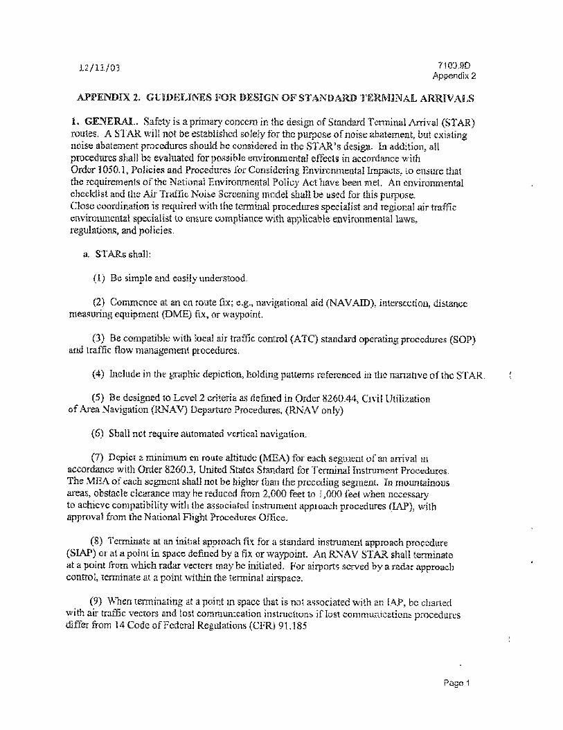
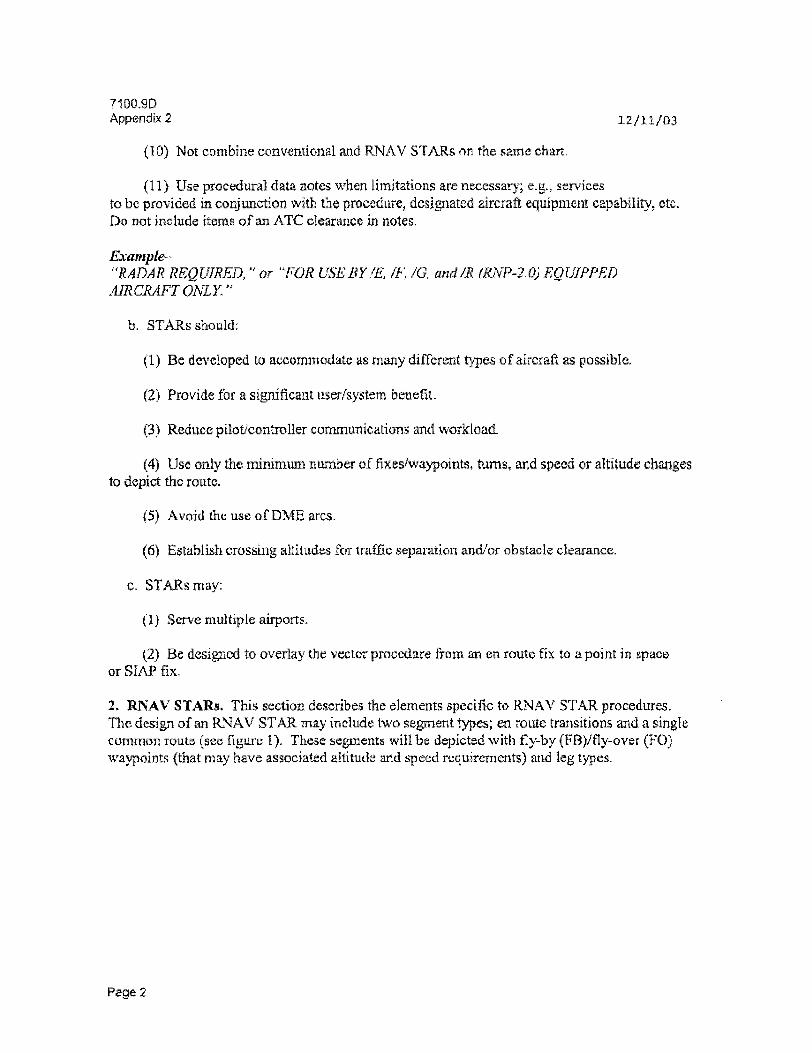
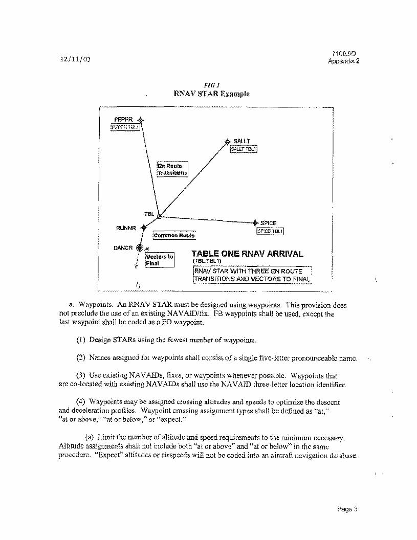
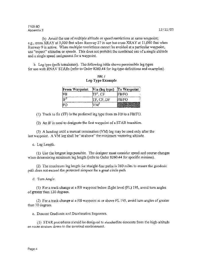
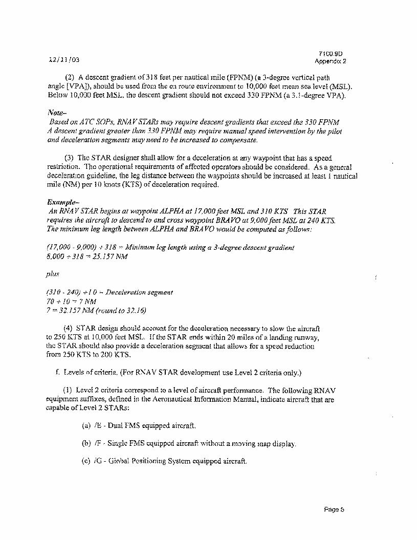
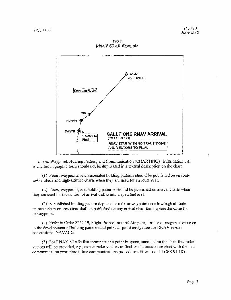
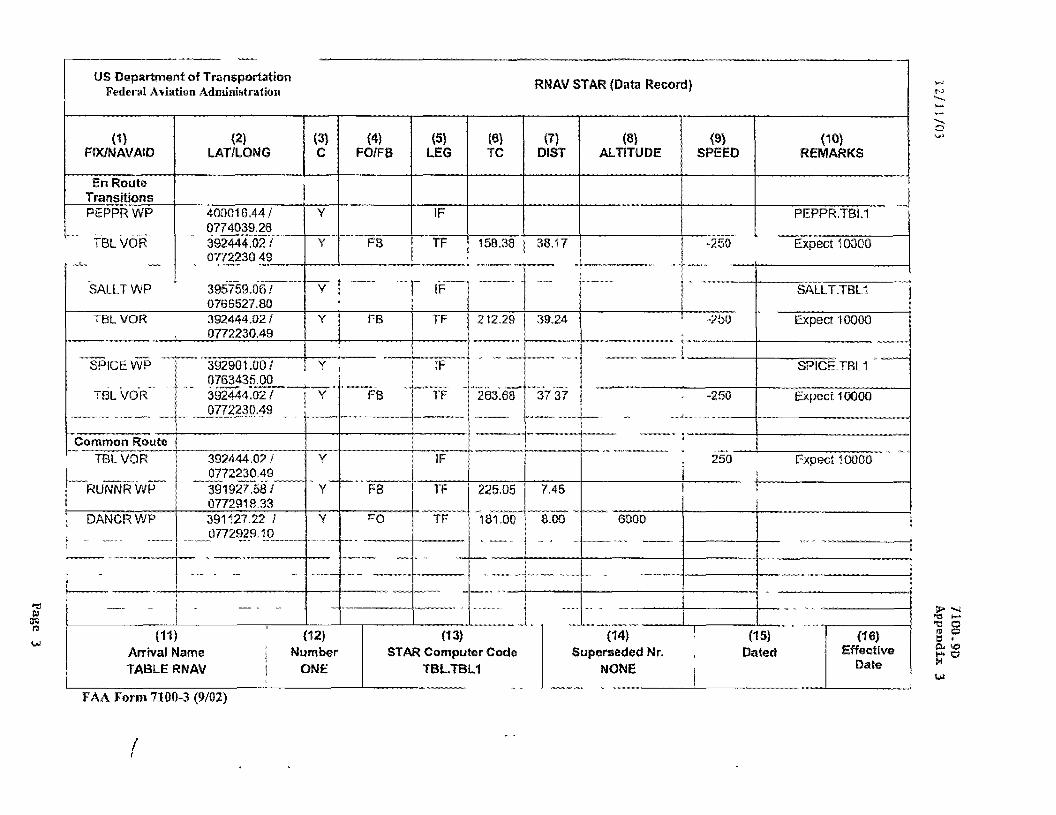
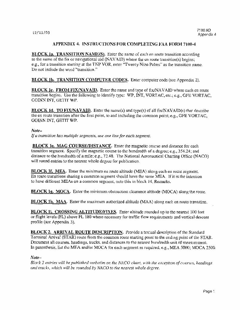
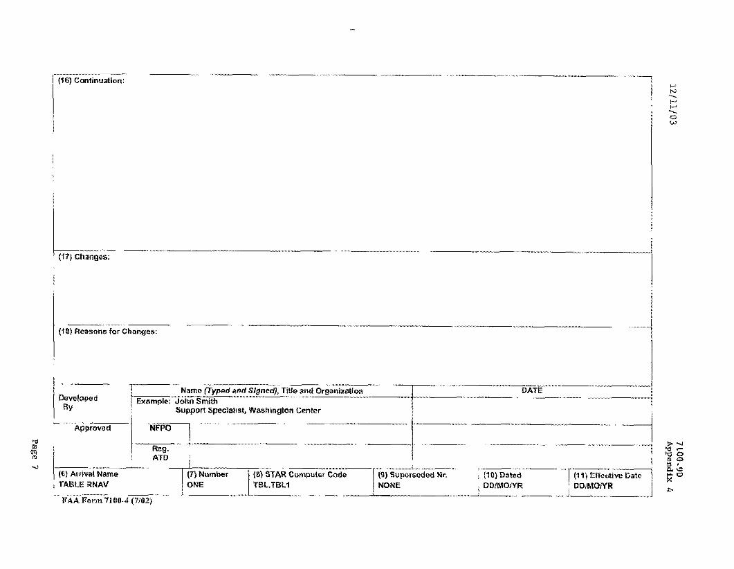

71009D Appendix 5 121103
(b) Determine need for working group participation by individualsorganizations not listed in table 1 Arrange for their participation as necessary
(c) Advise RNAV procedure proponent(s) to be prepared to present their proposals
(d) Advise Terminal Area Route Generation Evaluation and Traffic Simulation (TARGETS) tool operator to complete guideline item 2 Adaption of TARGETS Adapt TARGETS and be prepared to present a demonstration of TARGETS as needed
(2) Initial meeting
(a) Introduce the Guidelines for Implementing Terminal RNAV Procedures to include the participants roles and responsibilities from table 1
(b) Provide an overview of any ongoing RNAV development projects at the air traffic control (ATC) facility or elsewhere in the region
(c) Develop a mission statement that provides clear direction for the working group The mission statement should identify the projects goal
Example-Define develop and implement RNAV procedures and profiles in the New York Terminal Radar Approach Control (TRACON) facility airspace to increase safety reduce communications improve userprovider efficiencies and improve air transportation sendee to the traveling public at the John F Kennedy International Airport
(3) Administrative activities
(a) Develop a point of contact list using Fonn 4 Working Group Contact List
(b) In coordination with the Flight Procedures Office (FPO) establish a schedule for guideline item completion that meets the publication dale TARGETS contains a Microsoft project template of critical path and average timeline schedule for each item
(c) Establish telcon schedule
Note-After the kickoff meeting telcons are the primary metliod by which the working group meets They are used to coordinate activities ensure timely completion of project items refine issues verify completion of required work and to truck remaining items and critical schedule dependencies
(d) Identify the organization (usually the FAA regional office) responsible for establishing the telcon bridge Obtain the telephone number and access code
Page 2
121103 7 1 0 0 9 D
Appendix 5 (4) Post meeting requirements
Create and begm regular (as needed) distribution of project documentation to the working group This will generally consist of some or all of the following
(a) An e-mail documenting meeting or telcon attendees minutes of the previous meeting or telcon and the next meeting or telcon agenda
(b) An updated list o faction items and the guideline index
(c) The TARGETS RNAV distribution package which includes a PowerPoint diagram ot the procedure and a waypoint data table depictmg the latitudelongitude coordinates FAA leg types and when assigned altitudespeed for each waypoint
(d) Additional documentation as needed
Note-It is imperative that individuals with decisionmaking authority participate m teicons In certain cases it may be pr udent to cam el a telcon or even terminate a telcon in progress when key participants are not available This will reduce the need for post telcon coordination assist in consensus building and help to ensure all aspects of important issues arefully addressed
b TARGETS Operator
(1) Conduct demonstration of TARGETS if necessarj
(2) Operate TARGETS during preliminary and subsequent orocedure design activities
2 Adaptation of TARGETS
This item describes the activities required to prepare TARGETS for the site-specific procedute design Tire 1ARGEFS operator shall acquire and install the following data elements mto TARGETS
a Navigation Data
Provided by the National Flight Data Center (NFDC) on CD-ROM
b Video Maps
Digital maps provided m digital DAT format by the National Aeronautical Charting Office (NACO)
Page 3
71009D Appendix 5 121103
c Automated Radar Terminal Systems (ARTS)Standard Terminal Automation Replacement System (STARS) Data
ATC facility management provides ARTSSTARS data This data is used in TARGETS to confirm existing traffic flows This daia may also bs used in the construction of scenarios for controller familiarization and evaluation Sufficient track data should be installed to adequately characterize the traffic flows for the particular airportrunway configuration of interest
d Aircraft Performance Data
TARGETS is preconfigured with a set of generic aircraft performance that is used lor the flyability evaluations In addition specific aircraft performance data can be entered in TARGETS
3 Reserve Waypoiot Names
This item describes the steps necessary to reserve waypoint names and to reduce the possibility of duplicated name assignments
a ATC Facility Management
(1) Coordinate with the appropriate air route traffic control center (ARTCC) to reserve a block of waypoint names for the project
(2) Verify with the NFDC that the names have not already been used
b TARGETS Operator
Enter waypoint names into TARGETS
c Lead Operator
Verify with charting and navigation database suppher(s) that the names have not already been used
4 Design of Procedure
The item provides guidance for designing the procedure However it is imperative thai procedure designers consult the most current edition of the appropriate references before and during the design process
a ATC Facility Management
(1) Design considerations
Pa goshy
71009D 1 2 1 1 0 3
Appendix 5
(a) Follow the design guidance hsted in the following applicable FAA orders Order 826044 Civil Utilization of RNAV Departure Procedures Order 8260 46 Departure Procedure Program andor Order 71 KJy Standard Terminal Arrival when defining the procedure Additional guidance can be obtained from the regional project facilitator or the Regional Airspace Procedures Team (RAPT)
(b) Assign procedure and waypoint names in accordance with the naming conventions outlined m the applicable FAA order
(c) The procedure must pass a TARGETS flyability evaluation and comply with minimum segment length requirements If unable to comply coordination with the FPO is necessary
(2) Air traffic considerations
(a) Ensure all waypoints that are located near airspace boundaries are positioned to comply with required separation standards Waypoints located less than 40 miles from the radar antenna must be at least 35 nautical miles (NM) from the boundary and greater than 40 miles from the antenna must be at least 4 5 NMs
(b) Consider possible traffic conflicts eg piggybacks letters of agreement [LOAj routings other airport flows etc
(e) For departures where required ensure an interim altitude is given for each runwaytransition in the chart narrative eg MAINTAIN 3000 feet expect filed altitude 10 minutes after departure
(d) For procedures designed to overlay historical trackspattcrm cheek against the plotted ARTSSTARS data to verify that the procedures lateral track complies with current traffic flows
(e) Controller simulations using the TARGETS simulation (unction may be used to identify potential traffic conflicts or design issues See item 5 Simulator Evaluations
(f) Consider lost communication procedures and phraseology necessary for the procedure
(g) Solicit feedback from facility controllers on the procedures design and potential operational impacts
b FPO Verify Airport Magnetic Variation Being Used for Project
c TARGETS Operator
(1) Prior lo submitting the documentation to the FPO apply ATC facility selected names to all waypoints associated with the procedure
Pago 5
7100 9D Appendix 5 1 2 1 1 0 3
(2) Ensure that the TARGETS has tli2 correct magnetic variation for the airpon
(3) Build proposed RNAV procedure in TARGETS and perform flyability evaluation^)
(4) Create and distribute the TARGETS RNAV distribution package o the project facilitator for subsequent distribution to the remainder of the working group
d Lead Operator
(1) Obtain input on procedure design and navigation coding from a charting and database supplier
(2) Advise the principal operating inspector (POI) of the procedure design
(3) Identify and address flight deck human factors (TIF) issues Consider the impact of lateral navigation (LNAV) and veitical navigation (VNAV) procedure components on a vanety of aircraft con figurations
(4) For DPs coordinate with local air traffic management to identify and create runway position updating quick align (QA) waypoints Coordinate QA waypoint information with the regional 520amp530s Advise charting and database supplier for updates
5 Simulator Evaluations
This item provides guidance for simulator evaluations The purpose of aircraft simulator evaluations is to identify and resolve navigation database FAA leg type autoflight capabilities and HFs issues The purpose of ATC facility simulation is to identify and revive communication or operational impacts Simulator evaluations are not retmired but are strongly recommended They may occur anytime and should be repeated as necessary
a All Participants
Identify any special test conditions based on the procedures design or prevailing operating conditions that the lead operator should simulate e g if the first leg of the procedure is a heading leg the working group may want to simulate crosswind conditions during takeoff
b Lead Operator
(1) Obtain a database with coded procedure
(2) Evaluate the procedure in the simulator Alert the working group if it is necessary to evaluate the procedure in a simulator type not available to the lead operator
(3) Complete the output requirements for aircraft simulations Torm-5 RNAV Flight Simulator Worksheet and distribute the results to the working group
Page 6
71009D
121103 Appendix 5
(4) Report flyabihty or operational issues to the working group
Note-Coordinate simulator evaluation with the Policy and Standards Branch A VN-23G
c ATC Facility Management
(1) Evaluate the procedure using TARGETS andor the Enhanced Target Generator (ETG) as required
(2) Report any operational issues to the team for review
6 Working Group Review of Procedure
This item is intended to allow the entire RNAV Implementation Wotking Group an opportunity to review the procedure design from the TARGETS distribution package prior to completing and submitting the procedure documentation to the FPO
a All Participants
(1) Review the procedure to ensure it meets the mission statement developed during the kiekoff meeti rig
(2) Ensue that the procedure passes a TARGETS flyability evaluation and complies with minimum segment length requirements If unable to comply redesign the procedure or discuss waiver options with the FPO
b ATC Facility Management
(1) Review airspace issues waypoint placement in relationship to airspace boundaries crossing restrictions traffic conflicts and LOA routings
(2) Review the RNAV procedure for automation impacts (see item 9 Automation)
c Lead Operator
(1) Review navigation system database or operational issues
(2) Ensure any issues identified during simulator evaluations have been addressee (see item 5)
d FPOAU Weather Operation (AWO)
(1) Perform an initial Terminal Instrument Procedure (TERPS) and inability assessment If the procedure does not coirpiy with TERPS criteria or the flyability assessment the following actions need to occur as appropriate
Hage
7100 9D
Appendix 5 1 2 1 1 0 3
(a) Advise the working group of the failure
(b) In coordination with the working group revise the procedure (c) Consider making the proceduie a special andor apply for waivers to the
criteria with equivalent levels of safety defined
(d) Coordinate with the Flight Standards Service (AFS) regarding changes to design criteria
(2) Ensure that latitudelongitude values generated by TARGETS arc identical to the Aviation System Standards (AVN) AirNav database values If database differences are discovered coordinate with AVN for final determination Advise the TARGETS operator of the correct coordinates to use
Note-Tie possibility exists thai IheAirNav database may reflect different coordinates than the NFDC database because of recent changes ot revisions
(3) Provide writtenverbal authorization to the working group to continue with procedure development
c TARGETS Opeiatot
(1) Update the procedure design to incorporate feedback from the working group review
(2) After modifications arc complete distribute the TARGETS RNAV distribution package to the project facilitator
f ATC Facility ManagementRegional 520s530s
Determine the extent of the environmental reviews lequired (reference Order 10501D Policies and Procedures for Considering Environmental Impacts)
7 Process of Decision
This item is a key decision point The working gioup must reach consensus concermng whether to conduct flight trials or to proceed directly to public charting
a All Participants
(1) Determine the need lo conduct flight trials (specials) Consider route complexity eg overlay versus nonoerlay route compliance with applicable FAA orders ATC facility and lead operator comfort level
Page S
121103 71009D Appendix 5
(2) For flight trials
(a) Create procedure documents associated with a special as directed by the FPO
(b) Follow guidance forpreparing and conducting lead operator flight trials provided in item 16 Lead Operator Flight Trials
b Direct to Public Close item 16
8 Procedure Documentation
This step provides guidance for completion and submission of the required documentation to be submitted to the FPO for review and processing Procedure documentation must be submitted to the FPO in accordance with the Operational Evolution Plan (OEP) RNAV prioritization list to allow processing to be completed prior (o the publication date
a ATC Facility Management
(1) Confirm the waypoint names listed in the TARGETS distribution package are the same as the waypoints selected by ATC facility management
(2) Confirm the name of the procedure is in accordance with the applicable FAA order
(3) Upon completion of guideline item 6 Working Group Review of Procedure use the current TARGETS distribution package to complete and submit appropriate documentation in accordance with applicable FAA orders to the regional Air Traffic Division (ATD)
Note 7-For a Standard Terminal Arrival (STAR) complete the forms worksheets sectional charts and TARGETS distribution package as directed m FAAO 7100 9
Note 2shyFor a DP complete the worksheets and TARGETS distribution package as directed in FAAO S26046
b Regional ATD
(1) Review procedure documentation and submit to the FPO
(2) If the documentation requires any modification coordinate with the working group prior to making changes
(3) After completing procedure documentation review forward to the FPO for further processing
Page
7 1 0 0 9 0 1211gt03 Appendix 5
c FPOAWO
(1) Review the procedure documentation
(2) If tire documentation requires any modification coordinate with the working group prior to making changes
(3) For procedures intended for use byE IF andor R regardless of Required Navigation Performance (RNP) accuracy conduct a distance measuring equipment (DMEVDME assessment
(4) After completing procedut e documentation review forward to the National Flight Procedures Office (NFPO) for further processing
9 Automation
This item provides guidance on automation activities that should be completed prior to procedure implementation
a ATC Facility Management
(1) fcnsure coordination occurs between all effected facilities including first and second tier facilities Determine each participating facilitys specific automation requirements Reach consensus among the facilities as to how the procedure will be coded in the Host Comouter System (HCS) HCS coding options include
(a) For departures preferred departuie routes (PDR) preferred departure and arrival routes (PDAR) or standard instrument departure (SID) route records
(b) For arrivals preferred arrival loutes (PAR) or STAR route records
(2) Ensure that data tags and scratch pad requirements have been identified and addressed Close coordination between adjoining facilities is required to ensure the fix-pair information agrees at all facilities
(3) Review intcrfacilitymtrafacility handofi procedures for possible modifications to HCS or ARTSSTARS
(4) Evaluate the impact of the new procedure on ARI CC IICS and flight plan filing systems Ensure that an identified lbsues have been resolved
b Lead Operator
Identify necessary updates to the flight planning system database If an update is required identify the format requirements
Page 10
7100 9D 121103 Appendix 5
Note-Automation update cycles may have a significant impact or the flight trial and public charting implementation timelines
10 Environmental Review
ATC Facility ManagementRegional 520s530s
Complete required environmental reviews
Note-An en vironmental review must be completed for all proposed procedures For those reviews thai confirm the proposed change overlays existingflightpathsnofurther environmental review is required However the appropriate documentation should be prepared and included in the officialfile
11 Advise Industry of Project Development
a Regional 520s530s
(1) Advise industry groups (Air Transport Association Regional Airlines Association National Business Aircraft Association etc) of new procedure development and forward IARGETS distnbuion package
(2) Inform industry of any newly created runway position updating points (QA waypoints) See Fonn-6 Industry Notification
b Lead Operator
Bncf development status issues and lessons learned at Air Transport Association RNAV task force meetings
12 AVN Flight Check
This Hem provides guidance to ensure the AVN flight check is satisfactorily completed and the working group reviews the results
a AVN
(I) After the NFPO has completed a TERPS evaluation and quality control review complete a flight check
12) Dbtribute any flight ciew feedback on the procedure lo tie working group
b NFPO
Page 1
7100 9D A c 1 2 1 1 0 3
Appendix 5
Upon completion of a satisfactory flight check complete the appropriate forms Forward documentation of flight inspection and original forms to the NhDC for further piocessmg atd a copy to the regional ATD SID forms will be processed and sent directly ta the NFDC for publication
c ATC Facility Management
(1) Capture flight check ARTSSTARS track for review m TARGETS
(2) Document controller feedback
d All Participants
(1) Upon completion of the fliglit check review the recorded flight check tracks
m TARGETS
(2) Review the flight check crew and controller feedback
13 Video Maps This item provides guidance to ATC facility management to ensure that video maps have been updated to accommodate the new piocedure
a Determine if video map updates are required Be sure to consider all associated facilities
b If v ideo maps require updating submit change requests to NACO at least 30 days prior to either proccduie impiementaton or flight trials Tins allows sufficient time for procurement and instal lation
Note-Overlay procedutes that follow established traffic flows ma not require this item
14 1 raining and Notifications
I his item provides guidance for notifying and training pilots dispatchers and controllers
a ATC Facility Management
(1) Provide notice to controllers as required by the collective bargaining agreement between the National Air Traffic Controllei s Association (NATCA) and FAA
(2) Conduct impact and implementation (lampI) with NATCA m accordance with Article 7 of the collective bargaimng agreement between NATCA and the FAA Ensure training and IampJ will be completed prior to the start of the flight trials or procedure implementation
(3) Use TARGETS or ETG for controller familiarization with the new procedure
Page 1
71009D l Z 1 1 0 3 Appendix 5
(4) Controller training material should include but not be limited to the following
a Automated Terminal Information System (A flS) verbiage pliraseology and procedural changes necessary for the new procedure
b Lead Operator
(1) Prepare and distribute pilotdispatcher training aids and materials
(2) Distribute internal notification as required
(3) Additional guidance material should be provided for aircraft operating without VNAV capabilities on procedures with assigned altitudes
15 Process Verification
This item ensures all action items arc completed prior to implementing the new procedure
a ATC Facility Management
(1) For overlay procedures check final procedure design against plotted ARTSSTARS to verify the procedure matches the current flows
(2) Confirm Iampl with NATCA is completed and controller concernsissues have been resolved
(3) Confirm automation and handoff issues have been resolved (predeparture clearance [PDC] handoff strip handling etc)
(4) Confirm video map updates have been installed
(5) Coordinate with the David J Hurley Air Traffic Control System Command Center (ATCSCC) and consider the need for a National Airspace System (NAS) bulletin andor updates to the National Route Program This coordination is critical for special procedures
b Regional 520s
Ensure all environmental requirements have been met and the appropriate environmental documentation is part of the official file
c FPOAWO
(1) Confirm ail required forms have been completed and submitted
(2) CuiiHrin AVN fliglit check has been completed
Paue 13
i
7100 9D lt 1 2 1 3 0 3
Appendix 5 d LeadOpeiatoi
(1) Ensure all company issues eg POI Ops Spec flight planning system navigation database training etc are resolved
(2) If QA waypoints are required ensure they are available m the database prior to procedure implementation
16 Lead Operator Flight Trials
This item provides guidance for preparing and conducting lead operator flight trials The purpose of the flight trials is to evaluate the procedure design and provide an opportunity for a large sample of controllers and pilots to become familiar with the RNAV procedure Lead operator flight trials are revenue flights in which aircraft are assigned the procedure prior to public implementation Flight trials will be conducted as FAA specials only after having met all safety requirements AVN flight check and receiving AFSPOl approvals as required
a All Participants
(1) Establish flight tnal dates When establishing the start date consideration must be given to pilot dispatcher and controller training requirements charting and database cycles (add seven day buffer for distribution) fliglit planning systems impacts etc
(2) The flight trials should be scheduled over an established period of time eg 60 90 120 dayb
(3) Based on the results of the flight trials make decisions regarding the procedure design andor implementation date Consult item 18 Post Procedure Implementation Analysis
(4) Confirm item 15 Process Verification has been completed pnor to start of fliglit trials
(5) Conduct analysis per item 18
Note-If all parties agree the lead operator may continue to use the special procedure while thepuhhc charting process is completed
b Lead Operator
(1) Develop a tailored chan and navigation database for use during the flight trials (Provide working group with copies of chart)
(2) Receive POI approval prior to the btart of flight trials
(3) Develop pilot questionnaires lor distribution dunng the flight trials
Pcrje 14
7100 9D 1 2 1 ] 0 3 Appendix 5
(4) Ensure flight planning system updates have been completed and dispatchers are prepared prior to the start da6
c ATC Facilities
(1) Training and notification must be completed 30 days prior to the beginning of fliglit trials
(2) Collect ARTSSTARS data from these flights and using TARGETS compare to the piocedurc
17 Publish Procedure for Public Use
a AVNATD
Complete final procedure documentation and forward to NACO for publication
b All Participants
Confirm that navigation database coding of the procedure matches the charted depiction andor intent of the procedure The working group should contact a charting provider and the National Imagery and Mapping Agency (NIMA) to ensure that database coding meets operational needs prioi to publication
18 Postprocedure Implementation Analysis
This item provides guidance for the working group to collect and analyze data from the new procedure
a ATC Facility Management
(1) Establish a system for documenting and reporting instances when proceduie irregularities occur Include the following
(2) Aircraft identification (ID) date time ard person reporting
(3) A bnef description of where the aircraft deviated from the published flight path
(4) If possible archive the voice tapes and ARTS STARS tracks for future evaluation
(5) Collect and evaluate controller feedback
(6) Assess controller workload
(7) Identify operational issues and advise the working group of required changes to the nrocedurc
Pace 15
71009D Appendix 5 123103
b All Participants
(1) Review and analyze data collected bgt the ATC facility
(2) If necessary follow guidance in applicable FAA orders to modify the procedure
c Lead Operator
(1) Collect and evaluate pilot feedback (interview pilots as needed)
(2) Assess pilot workload
(3) Identify operational issues and advise the working group of required changes to the procedure
Page 16
1 2 1 1 0 3 71009D Appendix 5
Table 1 RNAV Implemenation Working Group
I he following is a list of participants that must be represented on the RNAV Implcmentaton Working Group and some of their associated responsibilities
Project Facilitator
a Designated by regional ATD following RAPT procedure prioritization process
b Focal point for coordinating working group activities
c Lead telcon discussions update project schedule and maintain all project documentation
d Assign and track opencompleted issues and tasks using the implementation guidelines
e Ensure working group consensus on open items in the guidelines prior to closure Provide updates to the working group on procedure status as needed
t Provide assistance to air traffic management ir the completion and submission of requiied worksheetsforms
2 TARGETS Operator
a Acq JUC and install video maps ARTSSI ARS data and NFDC navigation dan
b Maintain the most recem version of TARGETS wih an updated NFDC database
c Maintain the procedure assign in a TARGETS file Each update to the file should be saved with a unique easv to understand name that indicates chronological order of the project design eg CLTJSALEY 9-20-02 Save and maintain all files
d Peifoim flyabihty evaluations and create simulations as needed
3 Regional FPOAWO
a Provide mput on route design and review procedure design for compliance with ci itei la
b If due to local air traffic or environmental reasons the route cannot be designed lo conform to current criteria request assistance from AVNAFS concerning additional route design options or begin waiver pnxess if necessary
c Ensure waypoint latitudelongitude positions are conect
d Piovide an initial route design authorization to the working grojp
c Revew and forward procecuie documentation to the MPO
Page t
7100 9D bdquo 1 2 1 1 0 3
Appendix 5
4 Regional 520s530s
a i ovide support and resources required for procedure development
b Appoint a project facilitator for working group
c Provide a telcon bridge for working group teicons
ri Assign an environmental specialist lo review the proposed route for environmental impact provide guidance on co-npletion of required paperwork and forms (environmental checklist etc) for submission of the route and participate as pan of the working group
e Provide coordination regarding all regional activities and assist with FPQAWO coordination
f Bnef the RAPT flight teams headquarters etc as required or requested
5 AVNAFS
a Support lcgional FPOAWO personnel as requested
b The TPOAWO may request guidance i f a procedure docs not meet criteria If due to local air traffic or environmental reasons the route cannot be designed to conform to current criteria provide guidance on waiver options and assist in completion
6 Lead Operator
A Provide feedback on procedure design route flyamliry and potential navigation database design requirements The lead operators experttse with navigation systems is critical for successful procedure design
b If the lead operator has the capability be prepaied to conduct simulation andor flight trials of the procedures llyalnhty This may icquire obtaining an updaEed navigation database and tailored chart
c When simulator testing is accomplished record performance data utilizing Form 5 RNAV Flight Simulatoi Worksheet
d When necessarv provide pocedure data to other operatois for testing in additional aircraft types
c If the lead operator is ar air cainer coordinate with the FAA POI
Page 8
7 1 0 0 9 D 121103Appendix 5
7 1C Facility ManagementNATCA
a Provide the working group with information regarding traffic flows and ope-ationa considerations eg existing routes minimum instrument flight rules (IFR) altitudes facilitysector lateral and vertical airspace boundaries and airspeed restrictions
b Provide data depicting current or anticipated flight operations in order to define flight pathaltitudes profilesspeeds arrival departure separation procedures terminalen route information exchange and timing of contro actions
c Ensure that all ATC concerns arc addressed regarding procedure design implementation timetable and communication requirements
d Complete and submit requred procedure documentation
e If required update video maps at least 30 days prior to the start of the flight trials or public charting
f Complete all controller notifications 2nd training prior to start of the flight trials or public charting
8 ARTCC MaDagementNATCA
a Provide the proponent and participating facility with information regarding traffic flows and operational considerations
b Review handoff procedures crossing restrictions airspace boundary issues waypoint placement in relationslup to airspace boundaries crossing restrictions traffic conflicts and any LOA routings which may affect procedure design or implementation
c Provide names for waypoints created for the procedure
d Coordinate automation updates for the filing of STARs and DPs as required
e Ensure that all known controller concerns regarding design implementation timetable end working procedures are resolved
9 Airport Authority
a Provide input on procedure design and impacts to airport
b Assist in reviewing impacts to noise sensitive areas surrounding the ai-port
c Provide information concerning planned airport construction that may impact procedure implementation
Page 19
71009D Appendix 5 121103
Note-Any other parties determined to have a potential interest in the procedure may be included in the working group eg user groupsFMS manufacturers charting and database suppliers etc
Page 20
121103
Acronym
AFS ALT ARTCC ARTS ATA ATC ATCSCC ATCT ATD ATIS AVN AWO DME DP ETG FAA FMS FPO GPS HCS HF IampI ID IFR IRL LNAV LOA NACO NAS NATCA NAVAID NFDC NFPO NIMA OEP Ops Specs PAR PDAR PDC PDR POI QA RAPT
71009D Appendix 5
Table 2 Acronyms Terms and Definitions
Definition
Flight Standards Service Airspace Liaison Team Air Route Traffic Control Center Automated Radar Terminal Systems Air Traffic Airspace Management Air Traffc Control Air Traffic Control System Command Center Airport Traffic Control Tower Air Traffic Division Automated Terminal Information System Aviation System Standards All Weather Operations (associated with AFS) Distance Measuring Equipment Departure Procedure Enhanced Target Generator Federal Aviation Administration Flight Management System Flight Procedures Office Global Positioning System Host Computer System Human Factor Impact and Implementation Identification Instrument Flight Rules Inertial Reference Unit Lateral Navigation Letter of Agreement National Aeronautical Charting Office National Airspace System National Air Traffic Controllers Association Navigational Aid National Flight Data Center National Flight Procedures Office National Imagery and Mapping Agency Operational Evolution Plan Operations Specifications Preferred Arrival Route Preierred Departure and Arrival Route Predeparurre Clearance Preferred Departure Route Principal Operating Inspector Quick Align Regional Airspace Procedures Team
Page 21
7100 9D Appendix 5
REGIONAL 520530 RNAV RNP SID STAR STARS TARGETS
TERPS TRACON VNAV VORTAC
1 2 3 1 0 3
FAA Regional Office - Airspace Plans and Procedure Area Navigation Required Navigation Performance Standard Instrument Departure Standard Terminal Arrival Standard Terminal Automation Replacement System fenninal Area Route Generation Evaluation and Traffic Simulation Tool Terminal Instrument Procedures Terminal Radar Approach Control Vertical Navigation Collocated VOR and FACAN
Page 22
121103 71009D
Term
FAA Teg Type
Fix
Fly-Ry Waypoint
Fly-Over Waypoint
Guidelines
Lead Operator
Ops Specs
STAR
STAR Transition
Telcon Bridge
Waypoint
Appendix 5 Definition
The defined standard for aeronautical navigation databases that translates text and route information into computer readable code
A generic tenn used to define a predetermined geographical position used for route definition A fix may be a ground-based Navigational Aid (NAVAID) a waypoint or defined by reference to one or more radio NAVAEDs
A fly-by waypoint requires the use of turn anticipation to avoid overshoot of the next flight segment
A fly-over waypoint precludes any turn until the waypoint is over flown and may be followed by an intercept maneuver of the next flight segment
Guidelines for Implementing Terminal RKAV Procedures
An operator that has agreed to serve as the focal point for the development of DPSTARs at a specific airport
Airlines FAA approved Ops Specs governs the type of operations the airline is approved for and how the airline will comply with the FAA regulations
Standard Terminal Arrival - A preplanned IFR ATC arrival procedure published for pilot use in graphic andor textual form STARs provide transition from the en route structure to the terminal area
A published segment used to connect one or more en route airwaysjet routes to the basic STAR
A conference call that has a number of phone lines available Participants of the call must dial a designated phone number In the RNAV process the appropriate region office will create the telcon bridge when requested to do so by the RNAV Implementation Working Group
A predetermined geographical position that is defined in terms of latitudelongitude coordinates
Page 23
bull
bull
bull bull
bull
71009D Aopendix 5
Forni-1 Project Summary
Project Name
Prtwedttre PrcopypregHeiit(s)s Airports Served
Typet Arrival
121103
Proposed Publication Batreg
Departure Other
r RiinwaKsect)J
TraiwioiiCs) Mission Siateiiienfe
mdash mdash mdash
Tekraquon Phone Numbers TelcltMt Schedule gt
Access Code 1 (
Waypoint Names
Name Used Name Used Name Used Name Used
D D D D
j
bull
D bull D Q ( bull n
rr i bull 1 bull n bdquo bdquo bdquo _ _ _
bull bull i n bull i I D bull bull D
i1 n bull bull bull bull i L J laquo
bull bull gt
D D 1D D D bull
bull mdash mdash mdash mdash bull -g- n r i
Page 24
121103
Form-2 Guideline Item Index
71008D Appendix 5
(tem v
Start Date
Status
i Kickoff Meeting
l Adapt TARGETS
Reserve Waypoint Names
Design the Procedure
Simulator Evaluation
ji
Working Gioup Review of Procedtre
Process Decision
lt
i
Procedure Documentation i
Automation mdash mdash mdash -bull mdash shy - shy
_ _ _
s Envhunmental Review j
Adv i se Industry of Project k
Development
1
1 AVN Flight Check
Video Maps mdash - shy
|
Training and Notification
Process Verification _ _
Lead Operator Flight Trial 5
Publish Procedure foi Pubhc Use Post Procedure Implementation Analysts
Page 25
710090 Appendix 5 171101
Forni-3 Project Action Items
Action Item Assigned To Assign Date
Closed Bate Notes
1
-
i
i
i
Pago 26
121103 71009D Appendix 5
Form-4 Workimi Group Contact List Name Organization Phone Number E-Mail
i
f i
- _ _ bdquo _ bdquo bdquo bdquo _ _
_
I f
i i
i
Psgo 7
Form-5 RNAV Flight Simulator Worlcsheet
( 1) Operator Name See attachment for completion mstrcctions
(21 Procedure Name m Date
(4) Jype feg CARIZF] (5) LNAV VNAV lineags Point
(6) FMSGPS Manufacturer () FMSOPS Software Version
(g) Initial Wind Setup 10 K-TS or Maximum allowable tail wind on surface jncreasing to 30 KTS at 1000 feet then iacflampasebv 10 KTSevery 2000 feet until teachjaaSQ KTS
i^tSM R e a l Run 2 Rmt3 Rim4 Run S
(9) Ruiiwayaiid En Route Transition Flown
(10) Max allowable Takeoff Weight of Aircraft fli) Takeoff Throat used
Q2)Max SiirfaceTailwirid (SID only)
f3) Temperatuie (ISA)
(14) Type ofGujdariee
(15) Navigation Source
(16) Other
pound12LReinarks
(IS) Completed Bv (19) Phone Number
(20) Attach a print out of the FAA kg-type coding and a copy of the lateral aodjverjrical tiackromihc jproceduraflowR
O
Forrolaquo5 RNAV Flight Simutator Worksheet fContintied)
(21 Procedure Maine Run Complete tor Each Roe
K3
(21)WayfxjwitName - (221 Altitude - bull (23) Airsrx^JClcoimdsjaed
bull -- (M) Turn AnticioatioTt
Distance bull 1251 Wind
mdash mdash - shy mdash shy ~ shy
bdquo bdquo bdquo _ _ _ _ _ _ raquo _ _ bdquo _
mdashmdash-mdashmdashbull shy
1
j
mdash bull -
mdash - shy - - mdash _
i
i1 I
i
I
|
1
gt ^
tn
Instructions for Completing RNAV Flight Simulator Worksheet xr
w
J)
2)
1 3)
Rntert|ieoperator name
Enter the RNAV procedure name fep PAIGW RNAV five departure) Enterlhe date simxiladons were accomplished
1 sect
x
P
bullbullbull-~lt- -bull- laquo bull - trade ^
l 4) Enter the aircraft type and equipment suffix (eg CARJF 5) For standard instrument departures (SID) enter the point at which LNAVVNAV is engaged (as specified in operator operations manual)
6 Ejitet the FMS or GPS stand-alone manufacturers narraquog fejeHoncYweHSiniths1eK) 7) Enter the PMS or GPS stand-alone s o ft ware version 8) Use an in-tlieht tailwind of 30 KTS at 1 QQQ feet arid increase by 10 KTS every 2000 feet until reaching 80-KT tail wind (record wind u ed^mJMock aSJ
(Additionally for SIPs use crosm^dhearing opposite of first turn) 9) Enter the runway and en route transition flown 0) Enter tha takeoff weight - fly procedures at maximum allowable takeoff weight 11) Enter the takeoff thrust used - list either reduced or maximum takeoff settingiiBedXrrjgx^pwablebdquogervcojdx|ioas 12) Enter the surface tailwind - initiate takeoff with10-KT tailwind component 13) Enter the TSAiemperature - fly the procedure at average max summer temperature for the airport and use indicated climb gradients
14) Enter the type cf flight guidance used Tha preferred flight guidance is the autopilot List other if used fee flight director or CDR 15) Enter the navigation sensorreferenced whileflying the procedure (eaGPSsIRUDMEDME DMEDME) 16) Enter any working group specified conditions (eg crosswittd componerit) 1T) Enter any reoiarll about Aferarecediire^ W) Enter the name of poison completing the form 19) Enter an appfopriateeoMact phone number of the person conipleting form 20) Attach a print out of the leg type coding and lateral vertical trackforSMhlup fjown
21) bnttfi the name of WAypo t passed bv the aircraft (complete sheet for each ran completed)
22) Enter the aircraft altitude pacing the waypoint listed In box 21 23) bull nter the aircraft airground speed passing the waypoint listed in box 21 24) Enter the aircraft ten anticipation distance passing the waypoint listed in box 21 25) Enter the wind direction and veloc|tynassirig the waypomt listed in box21
o
121103 71009D Aapendix 5
Form-6 Industry Notification
Airport 1 Procedure Type I STAR [ J SID bull Other bull
Procedure Name j Expected Publication Date
Procedure BescrlpttenComrttente
Quick Align Waypoint Data (list name latitudelongitude)
Distribution Lists
j AOPA n ATA D NBAA f l RAA imdash
Other H
Note Attach TARGETS distribution package with this notification
Page 31
71009D Appendix 5 121103
c Automated Radar Terminal Systems (ARTS)Standard Terminal Automation Replacement System (STARS) Data
ATC facility management provides ARTSSTARS data This data is used in TARGETS to confirm existing traffic flows This daia may also bs used in the construction of scenarios for controller familiarization and evaluation Sufficient track data should be installed to adequately characterize the traffic flows for the particular airportrunway configuration of interest
d Aircraft Performance Data
TARGETS is preconfigured with a set of generic aircraft performance that is used lor the flyability evaluations In addition specific aircraft performance data can be entered in TARGETS
3 Reserve Waypoiot Names
This item describes the steps necessary to reserve waypoint names and to reduce the possibility of duplicated name assignments
a ATC Facility Management
(1) Coordinate with the appropriate air route traffic control center (ARTCC) to reserve a block of waypoint names for the project
(2) Verify with the NFDC that the names have not already been used
b TARGETS Operator
Enter waypoint names into TARGETS
c Lead Operator
Verify with charting and navigation database suppher(s) that the names have not already been used
4 Design of Procedure
The item provides guidance for designing the procedure However it is imperative thai procedure designers consult the most current edition of the appropriate references before and during the design process
a ATC Facility Management
(1) Design considerations
Pa goshy
71009D 1 2 1 1 0 3
Appendix 5
(a) Follow the design guidance hsted in the following applicable FAA orders Order 826044 Civil Utilization of RNAV Departure Procedures Order 8260 46 Departure Procedure Program andor Order 71 KJy Standard Terminal Arrival when defining the procedure Additional guidance can be obtained from the regional project facilitator or the Regional Airspace Procedures Team (RAPT)
(b) Assign procedure and waypoint names in accordance with the naming conventions outlined m the applicable FAA order
(c) The procedure must pass a TARGETS flyability evaluation and comply with minimum segment length requirements If unable to comply coordination with the FPO is necessary
(2) Air traffic considerations
(a) Ensure all waypoints that are located near airspace boundaries are positioned to comply with required separation standards Waypoints located less than 40 miles from the radar antenna must be at least 35 nautical miles (NM) from the boundary and greater than 40 miles from the antenna must be at least 4 5 NMs
(b) Consider possible traffic conflicts eg piggybacks letters of agreement [LOAj routings other airport flows etc
(e) For departures where required ensure an interim altitude is given for each runwaytransition in the chart narrative eg MAINTAIN 3000 feet expect filed altitude 10 minutes after departure
(d) For procedures designed to overlay historical trackspattcrm cheek against the plotted ARTSSTARS data to verify that the procedures lateral track complies with current traffic flows
(e) Controller simulations using the TARGETS simulation (unction may be used to identify potential traffic conflicts or design issues See item 5 Simulator Evaluations
(f) Consider lost communication procedures and phraseology necessary for the procedure
(g) Solicit feedback from facility controllers on the procedures design and potential operational impacts
b FPO Verify Airport Magnetic Variation Being Used for Project
c TARGETS Operator
(1) Prior lo submitting the documentation to the FPO apply ATC facility selected names to all waypoints associated with the procedure
Pago 5
7100 9D Appendix 5 1 2 1 1 0 3
(2) Ensure that the TARGETS has tli2 correct magnetic variation for the airpon
(3) Build proposed RNAV procedure in TARGETS and perform flyability evaluation^)
(4) Create and distribute the TARGETS RNAV distribution package o the project facilitator for subsequent distribution to the remainder of the working group
d Lead Operator
(1) Obtain input on procedure design and navigation coding from a charting and database supplier
(2) Advise the principal operating inspector (POI) of the procedure design
(3) Identify and address flight deck human factors (TIF) issues Consider the impact of lateral navigation (LNAV) and veitical navigation (VNAV) procedure components on a vanety of aircraft con figurations
(4) For DPs coordinate with local air traffic management to identify and create runway position updating quick align (QA) waypoints Coordinate QA waypoint information with the regional 520amp530s Advise charting and database supplier for updates
5 Simulator Evaluations
This item provides guidance for simulator evaluations The purpose of aircraft simulator evaluations is to identify and resolve navigation database FAA leg type autoflight capabilities and HFs issues The purpose of ATC facility simulation is to identify and revive communication or operational impacts Simulator evaluations are not retmired but are strongly recommended They may occur anytime and should be repeated as necessary
a All Participants
Identify any special test conditions based on the procedures design or prevailing operating conditions that the lead operator should simulate e g if the first leg of the procedure is a heading leg the working group may want to simulate crosswind conditions during takeoff
b Lead Operator
(1) Obtain a database with coded procedure
(2) Evaluate the procedure in the simulator Alert the working group if it is necessary to evaluate the procedure in a simulator type not available to the lead operator
(3) Complete the output requirements for aircraft simulations Torm-5 RNAV Flight Simulator Worksheet and distribute the results to the working group
Page 6
71009D
121103 Appendix 5
(4) Report flyabihty or operational issues to the working group
Note-Coordinate simulator evaluation with the Policy and Standards Branch A VN-23G
c ATC Facility Management
(1) Evaluate the procedure using TARGETS andor the Enhanced Target Generator (ETG) as required
(2) Report any operational issues to the team for review
6 Working Group Review of Procedure
This item is intended to allow the entire RNAV Implementation Wotking Group an opportunity to review the procedure design from the TARGETS distribution package prior to completing and submitting the procedure documentation to the FPO
a All Participants
(1) Review the procedure to ensure it meets the mission statement developed during the kiekoff meeti rig
(2) Ensue that the procedure passes a TARGETS flyability evaluation and complies with minimum segment length requirements If unable to comply redesign the procedure or discuss waiver options with the FPO
b ATC Facility Management
(1) Review airspace issues waypoint placement in relationship to airspace boundaries crossing restrictions traffic conflicts and LOA routings
(2) Review the RNAV procedure for automation impacts (see item 9 Automation)
c Lead Operator
(1) Review navigation system database or operational issues
(2) Ensure any issues identified during simulator evaluations have been addressee (see item 5)
d FPOAU Weather Operation (AWO)
(1) Perform an initial Terminal Instrument Procedure (TERPS) and inability assessment If the procedure does not coirpiy with TERPS criteria or the flyability assessment the following actions need to occur as appropriate
Hage
7100 9D
Appendix 5 1 2 1 1 0 3
(a) Advise the working group of the failure
(b) In coordination with the working group revise the procedure (c) Consider making the proceduie a special andor apply for waivers to the
criteria with equivalent levels of safety defined
(d) Coordinate with the Flight Standards Service (AFS) regarding changes to design criteria
(2) Ensure that latitudelongitude values generated by TARGETS arc identical to the Aviation System Standards (AVN) AirNav database values If database differences are discovered coordinate with AVN for final determination Advise the TARGETS operator of the correct coordinates to use
Note-Tie possibility exists thai IheAirNav database may reflect different coordinates than the NFDC database because of recent changes ot revisions
(3) Provide writtenverbal authorization to the working group to continue with procedure development
c TARGETS Opeiatot
(1) Update the procedure design to incorporate feedback from the working group review
(2) After modifications arc complete distribute the TARGETS RNAV distribution package to the project facilitator
f ATC Facility ManagementRegional 520s530s
Determine the extent of the environmental reviews lequired (reference Order 10501D Policies and Procedures for Considering Environmental Impacts)
7 Process of Decision
This item is a key decision point The working gioup must reach consensus concermng whether to conduct flight trials or to proceed directly to public charting
a All Participants
(1) Determine the need lo conduct flight trials (specials) Consider route complexity eg overlay versus nonoerlay route compliance with applicable FAA orders ATC facility and lead operator comfort level
Page S
121103 71009D Appendix 5
(2) For flight trials
(a) Create procedure documents associated with a special as directed by the FPO
(b) Follow guidance forpreparing and conducting lead operator flight trials provided in item 16 Lead Operator Flight Trials
b Direct to Public Close item 16
8 Procedure Documentation
This step provides guidance for completion and submission of the required documentation to be submitted to the FPO for review and processing Procedure documentation must be submitted to the FPO in accordance with the Operational Evolution Plan (OEP) RNAV prioritization list to allow processing to be completed prior (o the publication date
a ATC Facility Management
(1) Confirm the waypoint names listed in the TARGETS distribution package are the same as the waypoints selected by ATC facility management
(2) Confirm the name of the procedure is in accordance with the applicable FAA order
(3) Upon completion of guideline item 6 Working Group Review of Procedure use the current TARGETS distribution package to complete and submit appropriate documentation in accordance with applicable FAA orders to the regional Air Traffic Division (ATD)
Note 7-For a Standard Terminal Arrival (STAR) complete the forms worksheets sectional charts and TARGETS distribution package as directed m FAAO 7100 9
Note 2shyFor a DP complete the worksheets and TARGETS distribution package as directed in FAAO S26046
b Regional ATD
(1) Review procedure documentation and submit to the FPO
(2) If the documentation requires any modification coordinate with the working group prior to making changes
(3) After completing procedure documentation review forward to the FPO for further processing
Page
7 1 0 0 9 0 1211gt03 Appendix 5
c FPOAWO
(1) Review the procedure documentation
(2) If tire documentation requires any modification coordinate with the working group prior to making changes
(3) For procedures intended for use byE IF andor R regardless of Required Navigation Performance (RNP) accuracy conduct a distance measuring equipment (DMEVDME assessment
(4) After completing procedut e documentation review forward to the National Flight Procedures Office (NFPO) for further processing
9 Automation
This item provides guidance on automation activities that should be completed prior to procedure implementation
a ATC Facility Management
(1) fcnsure coordination occurs between all effected facilities including first and second tier facilities Determine each participating facilitys specific automation requirements Reach consensus among the facilities as to how the procedure will be coded in the Host Comouter System (HCS) HCS coding options include
(a) For departures preferred departuie routes (PDR) preferred departure and arrival routes (PDAR) or standard instrument departure (SID) route records
(b) For arrivals preferred arrival loutes (PAR) or STAR route records
(2) Ensure that data tags and scratch pad requirements have been identified and addressed Close coordination between adjoining facilities is required to ensure the fix-pair information agrees at all facilities
(3) Review intcrfacilitymtrafacility handofi procedures for possible modifications to HCS or ARTSSTARS
(4) Evaluate the impact of the new procedure on ARI CC IICS and flight plan filing systems Ensure that an identified lbsues have been resolved
b Lead Operator
Identify necessary updates to the flight planning system database If an update is required identify the format requirements
Page 10
7100 9D 121103 Appendix 5
Note-Automation update cycles may have a significant impact or the flight trial and public charting implementation timelines
10 Environmental Review
ATC Facility ManagementRegional 520s530s
Complete required environmental reviews
Note-An en vironmental review must be completed for all proposed procedures For those reviews thai confirm the proposed change overlays existingflightpathsnofurther environmental review is required However the appropriate documentation should be prepared and included in the officialfile
11 Advise Industry of Project Development
a Regional 520s530s
(1) Advise industry groups (Air Transport Association Regional Airlines Association National Business Aircraft Association etc) of new procedure development and forward IARGETS distnbuion package
(2) Inform industry of any newly created runway position updating points (QA waypoints) See Fonn-6 Industry Notification
b Lead Operator
Bncf development status issues and lessons learned at Air Transport Association RNAV task force meetings
12 AVN Flight Check
This Hem provides guidance to ensure the AVN flight check is satisfactorily completed and the working group reviews the results
a AVN
(I) After the NFPO has completed a TERPS evaluation and quality control review complete a flight check
12) Dbtribute any flight ciew feedback on the procedure lo tie working group
b NFPO
Page 1
7100 9D A c 1 2 1 1 0 3
Appendix 5
Upon completion of a satisfactory flight check complete the appropriate forms Forward documentation of flight inspection and original forms to the NhDC for further piocessmg atd a copy to the regional ATD SID forms will be processed and sent directly ta the NFDC for publication
c ATC Facility Management
(1) Capture flight check ARTSSTARS track for review m TARGETS
(2) Document controller feedback
d All Participants
(1) Upon completion of the fliglit check review the recorded flight check tracks
m TARGETS
(2) Review the flight check crew and controller feedback
13 Video Maps This item provides guidance to ATC facility management to ensure that video maps have been updated to accommodate the new piocedure
a Determine if video map updates are required Be sure to consider all associated facilities
b If v ideo maps require updating submit change requests to NACO at least 30 days prior to either proccduie impiementaton or flight trials Tins allows sufficient time for procurement and instal lation
Note-Overlay procedutes that follow established traffic flows ma not require this item
14 1 raining and Notifications
I his item provides guidance for notifying and training pilots dispatchers and controllers
a ATC Facility Management
(1) Provide notice to controllers as required by the collective bargaining agreement between the National Air Traffic Controllei s Association (NATCA) and FAA
(2) Conduct impact and implementation (lampI) with NATCA m accordance with Article 7 of the collective bargaimng agreement between NATCA and the FAA Ensure training and IampJ will be completed prior to the start of the flight trials or procedure implementation
(3) Use TARGETS or ETG for controller familiarization with the new procedure
Page 1
71009D l Z 1 1 0 3 Appendix 5
(4) Controller training material should include but not be limited to the following
a Automated Terminal Information System (A flS) verbiage pliraseology and procedural changes necessary for the new procedure
b Lead Operator
(1) Prepare and distribute pilotdispatcher training aids and materials
(2) Distribute internal notification as required
(3) Additional guidance material should be provided for aircraft operating without VNAV capabilities on procedures with assigned altitudes
15 Process Verification
This item ensures all action items arc completed prior to implementing the new procedure
a ATC Facility Management
(1) For overlay procedures check final procedure design against plotted ARTSSTARS to verify the procedure matches the current flows
(2) Confirm Iampl with NATCA is completed and controller concernsissues have been resolved
(3) Confirm automation and handoff issues have been resolved (predeparture clearance [PDC] handoff strip handling etc)
(4) Confirm video map updates have been installed
(5) Coordinate with the David J Hurley Air Traffic Control System Command Center (ATCSCC) and consider the need for a National Airspace System (NAS) bulletin andor updates to the National Route Program This coordination is critical for special procedures
b Regional 520s
Ensure all environmental requirements have been met and the appropriate environmental documentation is part of the official file
c FPOAWO
(1) Confirm ail required forms have been completed and submitted
(2) CuiiHrin AVN fliglit check has been completed
Paue 13
i
7100 9D lt 1 2 1 3 0 3
Appendix 5 d LeadOpeiatoi
(1) Ensure all company issues eg POI Ops Spec flight planning system navigation database training etc are resolved
(2) If QA waypoints are required ensure they are available m the database prior to procedure implementation
16 Lead Operator Flight Trials
This item provides guidance for preparing and conducting lead operator flight trials The purpose of the flight trials is to evaluate the procedure design and provide an opportunity for a large sample of controllers and pilots to become familiar with the RNAV procedure Lead operator flight trials are revenue flights in which aircraft are assigned the procedure prior to public implementation Flight trials will be conducted as FAA specials only after having met all safety requirements AVN flight check and receiving AFSPOl approvals as required
a All Participants
(1) Establish flight tnal dates When establishing the start date consideration must be given to pilot dispatcher and controller training requirements charting and database cycles (add seven day buffer for distribution) fliglit planning systems impacts etc
(2) The flight trials should be scheduled over an established period of time eg 60 90 120 dayb
(3) Based on the results of the flight trials make decisions regarding the procedure design andor implementation date Consult item 18 Post Procedure Implementation Analysis
(4) Confirm item 15 Process Verification has been completed pnor to start of fliglit trials
(5) Conduct analysis per item 18
Note-If all parties agree the lead operator may continue to use the special procedure while thepuhhc charting process is completed
b Lead Operator
(1) Develop a tailored chan and navigation database for use during the flight trials (Provide working group with copies of chart)
(2) Receive POI approval prior to the btart of flight trials
(3) Develop pilot questionnaires lor distribution dunng the flight trials
Pcrje 14
7100 9D 1 2 1 ] 0 3 Appendix 5
(4) Ensure flight planning system updates have been completed and dispatchers are prepared prior to the start da6
c ATC Facilities
(1) Training and notification must be completed 30 days prior to the beginning of fliglit trials
(2) Collect ARTSSTARS data from these flights and using TARGETS compare to the piocedurc
17 Publish Procedure for Public Use
a AVNATD
Complete final procedure documentation and forward to NACO for publication
b All Participants
Confirm that navigation database coding of the procedure matches the charted depiction andor intent of the procedure The working group should contact a charting provider and the National Imagery and Mapping Agency (NIMA) to ensure that database coding meets operational needs prioi to publication
18 Postprocedure Implementation Analysis
This item provides guidance for the working group to collect and analyze data from the new procedure
a ATC Facility Management
(1) Establish a system for documenting and reporting instances when proceduie irregularities occur Include the following
(2) Aircraft identification (ID) date time ard person reporting
(3) A bnef description of where the aircraft deviated from the published flight path
(4) If possible archive the voice tapes and ARTS STARS tracks for future evaluation
(5) Collect and evaluate controller feedback
(6) Assess controller workload
(7) Identify operational issues and advise the working group of required changes to the nrocedurc
Pace 15
71009D Appendix 5 123103
b All Participants
(1) Review and analyze data collected bgt the ATC facility
(2) If necessary follow guidance in applicable FAA orders to modify the procedure
c Lead Operator
(1) Collect and evaluate pilot feedback (interview pilots as needed)
(2) Assess pilot workload
(3) Identify operational issues and advise the working group of required changes to the procedure
Page 16
1 2 1 1 0 3 71009D Appendix 5
Table 1 RNAV Implemenation Working Group
I he following is a list of participants that must be represented on the RNAV Implcmentaton Working Group and some of their associated responsibilities
Project Facilitator
a Designated by regional ATD following RAPT procedure prioritization process
b Focal point for coordinating working group activities
c Lead telcon discussions update project schedule and maintain all project documentation
d Assign and track opencompleted issues and tasks using the implementation guidelines
e Ensure working group consensus on open items in the guidelines prior to closure Provide updates to the working group on procedure status as needed
t Provide assistance to air traffic management ir the completion and submission of requiied worksheetsforms
2 TARGETS Operator
a Acq JUC and install video maps ARTSSI ARS data and NFDC navigation dan
b Maintain the most recem version of TARGETS wih an updated NFDC database
c Maintain the procedure assign in a TARGETS file Each update to the file should be saved with a unique easv to understand name that indicates chronological order of the project design eg CLTJSALEY 9-20-02 Save and maintain all files
d Peifoim flyabihty evaluations and create simulations as needed
3 Regional FPOAWO
a Provide mput on route design and review procedure design for compliance with ci itei la
b If due to local air traffic or environmental reasons the route cannot be designed lo conform to current criteria request assistance from AVNAFS concerning additional route design options or begin waiver pnxess if necessary
c Ensure waypoint latitudelongitude positions are conect
d Piovide an initial route design authorization to the working grojp
c Revew and forward procecuie documentation to the MPO
Page t
7100 9D bdquo 1 2 1 1 0 3
Appendix 5
4 Regional 520s530s
a i ovide support and resources required for procedure development
b Appoint a project facilitator for working group
c Provide a telcon bridge for working group teicons
ri Assign an environmental specialist lo review the proposed route for environmental impact provide guidance on co-npletion of required paperwork and forms (environmental checklist etc) for submission of the route and participate as pan of the working group
e Provide coordination regarding all regional activities and assist with FPQAWO coordination
f Bnef the RAPT flight teams headquarters etc as required or requested
5 AVNAFS
a Support lcgional FPOAWO personnel as requested
b The TPOAWO may request guidance i f a procedure docs not meet criteria If due to local air traffic or environmental reasons the route cannot be designed to conform to current criteria provide guidance on waiver options and assist in completion
6 Lead Operator
A Provide feedback on procedure design route flyamliry and potential navigation database design requirements The lead operators experttse with navigation systems is critical for successful procedure design
b If the lead operator has the capability be prepaied to conduct simulation andor flight trials of the procedures llyalnhty This may icquire obtaining an updaEed navigation database and tailored chart
c When simulator testing is accomplished record performance data utilizing Form 5 RNAV Flight Simulatoi Worksheet
d When necessarv provide pocedure data to other operatois for testing in additional aircraft types
c If the lead operator is ar air cainer coordinate with the FAA POI
Page 8
7 1 0 0 9 D 121103Appendix 5
7 1C Facility ManagementNATCA
a Provide the working group with information regarding traffic flows and ope-ationa considerations eg existing routes minimum instrument flight rules (IFR) altitudes facilitysector lateral and vertical airspace boundaries and airspeed restrictions
b Provide data depicting current or anticipated flight operations in order to define flight pathaltitudes profilesspeeds arrival departure separation procedures terminalen route information exchange and timing of contro actions
c Ensure that all ATC concerns arc addressed regarding procedure design implementation timetable and communication requirements
d Complete and submit requred procedure documentation
e If required update video maps at least 30 days prior to the start of the flight trials or public charting
f Complete all controller notifications 2nd training prior to start of the flight trials or public charting
8 ARTCC MaDagementNATCA
a Provide the proponent and participating facility with information regarding traffic flows and operational considerations
b Review handoff procedures crossing restrictions airspace boundary issues waypoint placement in relationslup to airspace boundaries crossing restrictions traffic conflicts and any LOA routings which may affect procedure design or implementation
c Provide names for waypoints created for the procedure
d Coordinate automation updates for the filing of STARs and DPs as required
e Ensure that all known controller concerns regarding design implementation timetable end working procedures are resolved
9 Airport Authority
a Provide input on procedure design and impacts to airport
b Assist in reviewing impacts to noise sensitive areas surrounding the ai-port
c Provide information concerning planned airport construction that may impact procedure implementation
Page 19
71009D Appendix 5 121103
Note-Any other parties determined to have a potential interest in the procedure may be included in the working group eg user groupsFMS manufacturers charting and database suppliers etc
Page 20
121103
Acronym
AFS ALT ARTCC ARTS ATA ATC ATCSCC ATCT ATD ATIS AVN AWO DME DP ETG FAA FMS FPO GPS HCS HF IampI ID IFR IRL LNAV LOA NACO NAS NATCA NAVAID NFDC NFPO NIMA OEP Ops Specs PAR PDAR PDC PDR POI QA RAPT
71009D Appendix 5
Table 2 Acronyms Terms and Definitions
Definition
Flight Standards Service Airspace Liaison Team Air Route Traffic Control Center Automated Radar Terminal Systems Air Traffic Airspace Management Air Traffc Control Air Traffic Control System Command Center Airport Traffic Control Tower Air Traffic Division Automated Terminal Information System Aviation System Standards All Weather Operations (associated with AFS) Distance Measuring Equipment Departure Procedure Enhanced Target Generator Federal Aviation Administration Flight Management System Flight Procedures Office Global Positioning System Host Computer System Human Factor Impact and Implementation Identification Instrument Flight Rules Inertial Reference Unit Lateral Navigation Letter of Agreement National Aeronautical Charting Office National Airspace System National Air Traffic Controllers Association Navigational Aid National Flight Data Center National Flight Procedures Office National Imagery and Mapping Agency Operational Evolution Plan Operations Specifications Preferred Arrival Route Preierred Departure and Arrival Route Predeparurre Clearance Preferred Departure Route Principal Operating Inspector Quick Align Regional Airspace Procedures Team
Page 21
7100 9D Appendix 5
REGIONAL 520530 RNAV RNP SID STAR STARS TARGETS
TERPS TRACON VNAV VORTAC
1 2 3 1 0 3
FAA Regional Office - Airspace Plans and Procedure Area Navigation Required Navigation Performance Standard Instrument Departure Standard Terminal Arrival Standard Terminal Automation Replacement System fenninal Area Route Generation Evaluation and Traffic Simulation Tool Terminal Instrument Procedures Terminal Radar Approach Control Vertical Navigation Collocated VOR and FACAN
Page 22
121103 71009D
Term
FAA Teg Type
Fix
Fly-Ry Waypoint
Fly-Over Waypoint
Guidelines
Lead Operator
Ops Specs
STAR
STAR Transition
Telcon Bridge
Waypoint
Appendix 5 Definition
The defined standard for aeronautical navigation databases that translates text and route information into computer readable code
A generic tenn used to define a predetermined geographical position used for route definition A fix may be a ground-based Navigational Aid (NAVAID) a waypoint or defined by reference to one or more radio NAVAEDs
A fly-by waypoint requires the use of turn anticipation to avoid overshoot of the next flight segment
A fly-over waypoint precludes any turn until the waypoint is over flown and may be followed by an intercept maneuver of the next flight segment
Guidelines for Implementing Terminal RKAV Procedures
An operator that has agreed to serve as the focal point for the development of DPSTARs at a specific airport
Airlines FAA approved Ops Specs governs the type of operations the airline is approved for and how the airline will comply with the FAA regulations
Standard Terminal Arrival - A preplanned IFR ATC arrival procedure published for pilot use in graphic andor textual form STARs provide transition from the en route structure to the terminal area
A published segment used to connect one or more en route airwaysjet routes to the basic STAR
A conference call that has a number of phone lines available Participants of the call must dial a designated phone number In the RNAV process the appropriate region office will create the telcon bridge when requested to do so by the RNAV Implementation Working Group
A predetermined geographical position that is defined in terms of latitudelongitude coordinates
Page 23
bull
bull
bull bull
bull
71009D Aopendix 5
Forni-1 Project Summary
Project Name
Prtwedttre PrcopypregHeiit(s)s Airports Served
Typet Arrival
121103
Proposed Publication Batreg
Departure Other
r RiinwaKsect)J
TraiwioiiCs) Mission Siateiiienfe
mdash mdash mdash
Tekraquon Phone Numbers TelcltMt Schedule gt
Access Code 1 (
Waypoint Names
Name Used Name Used Name Used Name Used
D D D D
j
bull
D bull D Q ( bull n
rr i bull 1 bull n bdquo bdquo bdquo _ _ _
bull bull i n bull i I D bull bull D
i1 n bull bull bull bull i L J laquo
bull bull gt
D D 1D D D bull
bull mdash mdash mdash mdash bull -g- n r i
Page 24
121103
Form-2 Guideline Item Index
71008D Appendix 5
(tem v
Start Date
Status
i Kickoff Meeting
l Adapt TARGETS
Reserve Waypoint Names
Design the Procedure
Simulator Evaluation
ji
Working Gioup Review of Procedtre
Process Decision
lt
i
Procedure Documentation i
Automation mdash mdash mdash -bull mdash shy - shy
_ _ _
s Envhunmental Review j
Adv i se Industry of Project k
Development
1
1 AVN Flight Check
Video Maps mdash - shy
|
Training and Notification
Process Verification _ _
Lead Operator Flight Trial 5
Publish Procedure foi Pubhc Use Post Procedure Implementation Analysts
Page 25
710090 Appendix 5 171101
Forni-3 Project Action Items
Action Item Assigned To Assign Date
Closed Bate Notes
1
-
i
i
i
Pago 26
121103 71009D Appendix 5
Form-4 Workimi Group Contact List Name Organization Phone Number E-Mail
i
f i
- _ _ bdquo _ bdquo bdquo bdquo _ _
_
I f
i i
i
Psgo 7
Form-5 RNAV Flight Simulator Worlcsheet
( 1) Operator Name See attachment for completion mstrcctions
(21 Procedure Name m Date
(4) Jype feg CARIZF] (5) LNAV VNAV lineags Point
(6) FMSGPS Manufacturer () FMSOPS Software Version
(g) Initial Wind Setup 10 K-TS or Maximum allowable tail wind on surface jncreasing to 30 KTS at 1000 feet then iacflampasebv 10 KTSevery 2000 feet until teachjaaSQ KTS
i^tSM R e a l Run 2 Rmt3 Rim4 Run S
(9) Ruiiwayaiid En Route Transition Flown
(10) Max allowable Takeoff Weight of Aircraft fli) Takeoff Throat used
Q2)Max SiirfaceTailwirid (SID only)
f3) Temperatuie (ISA)
(14) Type ofGujdariee
(15) Navigation Source
(16) Other
pound12LReinarks
(IS) Completed Bv (19) Phone Number
(20) Attach a print out of the FAA kg-type coding and a copy of the lateral aodjverjrical tiackromihc jproceduraflowR
O
Forrolaquo5 RNAV Flight Simutator Worksheet fContintied)
(21 Procedure Maine Run Complete tor Each Roe
K3
(21)WayfxjwitName - (221 Altitude - bull (23) Airsrx^JClcoimdsjaed
bull -- (M) Turn AnticioatioTt
Distance bull 1251 Wind
mdash mdash - shy mdash shy ~ shy
bdquo bdquo bdquo _ _ _ _ _ _ raquo _ _ bdquo _
mdashmdash-mdashmdashbull shy
1
j
mdash bull -
mdash - shy - - mdash _
i
i1 I
i
I
|
1
gt ^
tn
Instructions for Completing RNAV Flight Simulator Worksheet xr
w
J)
2)
1 3)
Rntert|ieoperator name
Enter the RNAV procedure name fep PAIGW RNAV five departure) Enterlhe date simxiladons were accomplished
1 sect
x
P
bullbullbull-~lt- -bull- laquo bull - trade ^
l 4) Enter the aircraft type and equipment suffix (eg CARJF 5) For standard instrument departures (SID) enter the point at which LNAVVNAV is engaged (as specified in operator operations manual)
6 Ejitet the FMS or GPS stand-alone manufacturers narraquog fejeHoncYweHSiniths1eK) 7) Enter the PMS or GPS stand-alone s o ft ware version 8) Use an in-tlieht tailwind of 30 KTS at 1 QQQ feet arid increase by 10 KTS every 2000 feet until reaching 80-KT tail wind (record wind u ed^mJMock aSJ
(Additionally for SIPs use crosm^dhearing opposite of first turn) 9) Enter the runway and en route transition flown 0) Enter tha takeoff weight - fly procedures at maximum allowable takeoff weight 11) Enter the takeoff thrust used - list either reduced or maximum takeoff settingiiBedXrrjgx^pwablebdquogervcojdx|ioas 12) Enter the surface tailwind - initiate takeoff with10-KT tailwind component 13) Enter the TSAiemperature - fly the procedure at average max summer temperature for the airport and use indicated climb gradients
14) Enter the type cf flight guidance used Tha preferred flight guidance is the autopilot List other if used fee flight director or CDR 15) Enter the navigation sensorreferenced whileflying the procedure (eaGPSsIRUDMEDME DMEDME) 16) Enter any working group specified conditions (eg crosswittd componerit) 1T) Enter any reoiarll about Aferarecediire^ W) Enter the name of poison completing the form 19) Enter an appfopriateeoMact phone number of the person conipleting form 20) Attach a print out of the leg type coding and lateral vertical trackforSMhlup fjown
21) bnttfi the name of WAypo t passed bv the aircraft (complete sheet for each ran completed)
22) Enter the aircraft altitude pacing the waypoint listed In box 21 23) bull nter the aircraft airground speed passing the waypoint listed in box 21 24) Enter the aircraft ten anticipation distance passing the waypoint listed in box 21 25) Enter the wind direction and veloc|tynassirig the waypomt listed in box21
o
121103 71009D Aapendix 5
Form-6 Industry Notification
Airport 1 Procedure Type I STAR [ J SID bull Other bull
Procedure Name j Expected Publication Date
Procedure BescrlpttenComrttente
Quick Align Waypoint Data (list name latitudelongitude)
Distribution Lists
j AOPA n ATA D NBAA f l RAA imdash
Other H
Note Attach TARGETS distribution package with this notification
Page 31

121103 71009D Appendix 5
(2) For flight trials
(a) Create procedure documents associated with a special as directed by the FPO
(b) Follow guidance forpreparing and conducting lead operator flight trials provided in item 16 Lead Operator Flight Trials
b Direct to Public Close item 16
8 Procedure Documentation
This step provides guidance for completion and submission of the required documentation to be submitted to the FPO for review and processing Procedure documentation must be submitted to the FPO in accordance with the Operational Evolution Plan (OEP) RNAV prioritization list to allow processing to be completed prior (o the publication date
a ATC Facility Management
(1) Confirm the waypoint names listed in the TARGETS distribution package are the same as the waypoints selected by ATC facility management
(2) Confirm the name of the procedure is in accordance with the applicable FAA order
(3) Upon completion of guideline item 6 Working Group Review of Procedure use the current TARGETS distribution package to complete and submit appropriate documentation in accordance with applicable FAA orders to the regional Air Traffic Division (ATD)
Note 7-For a Standard Terminal Arrival (STAR) complete the forms worksheets sectional charts and TARGETS distribution package as directed m FAAO 7100 9
Note 2shyFor a DP complete the worksheets and TARGETS distribution package as directed in FAAO S26046
b Regional ATD
(1) Review procedure documentation and submit to the FPO
(2) If the documentation requires any modification coordinate with the working group prior to making changes
(3) After completing procedure documentation review forward to the FPO for further processing
Page
7 1 0 0 9 0 1211gt03 Appendix 5
c FPOAWO
(1) Review the procedure documentation
(2) If tire documentation requires any modification coordinate with the working group prior to making changes
(3) For procedures intended for use byE IF andor R regardless of Required Navigation Performance (RNP) accuracy conduct a distance measuring equipment (DMEVDME assessment
(4) After completing procedut e documentation review forward to the National Flight Procedures Office (NFPO) for further processing
9 Automation
This item provides guidance on automation activities that should be completed prior to procedure implementation
a ATC Facility Management
(1) fcnsure coordination occurs between all effected facilities including first and second tier facilities Determine each participating facilitys specific automation requirements Reach consensus among the facilities as to how the procedure will be coded in the Host Comouter System (HCS) HCS coding options include
(a) For departures preferred departuie routes (PDR) preferred departure and arrival routes (PDAR) or standard instrument departure (SID) route records
(b) For arrivals preferred arrival loutes (PAR) or STAR route records
(2) Ensure that data tags and scratch pad requirements have been identified and addressed Close coordination between adjoining facilities is required to ensure the fix-pair information agrees at all facilities
(3) Review intcrfacilitymtrafacility handofi procedures for possible modifications to HCS or ARTSSTARS
(4) Evaluate the impact of the new procedure on ARI CC IICS and flight plan filing systems Ensure that an identified lbsues have been resolved
b Lead Operator
Identify necessary updates to the flight planning system database If an update is required identify the format requirements
Page 10
7100 9D 121103 Appendix 5
Note-Automation update cycles may have a significant impact or the flight trial and public charting implementation timelines
10 Environmental Review
ATC Facility ManagementRegional 520s530s
Complete required environmental reviews
Note-An en vironmental review must be completed for all proposed procedures For those reviews thai confirm the proposed change overlays existingflightpathsnofurther environmental review is required However the appropriate documentation should be prepared and included in the officialfile
11 Advise Industry of Project Development
a Regional 520s530s
(1) Advise industry groups (Air Transport Association Regional Airlines Association National Business Aircraft Association etc) of new procedure development and forward IARGETS distnbuion package
(2) Inform industry of any newly created runway position updating points (QA waypoints) See Fonn-6 Industry Notification
b Lead Operator
Bncf development status issues and lessons learned at Air Transport Association RNAV task force meetings
12 AVN Flight Check
This Hem provides guidance to ensure the AVN flight check is satisfactorily completed and the working group reviews the results
a AVN
(I) After the NFPO has completed a TERPS evaluation and quality control review complete a flight check
12) Dbtribute any flight ciew feedback on the procedure lo tie working group
b NFPO
Page 1
7100 9D A c 1 2 1 1 0 3
Appendix 5
Upon completion of a satisfactory flight check complete the appropriate forms Forward documentation of flight inspection and original forms to the NhDC for further piocessmg atd a copy to the regional ATD SID forms will be processed and sent directly ta the NFDC for publication
c ATC Facility Management
(1) Capture flight check ARTSSTARS track for review m TARGETS
(2) Document controller feedback
d All Participants
(1) Upon completion of the fliglit check review the recorded flight check tracks
m TARGETS
(2) Review the flight check crew and controller feedback
13 Video Maps This item provides guidance to ATC facility management to ensure that video maps have been updated to accommodate the new piocedure
a Determine if video map updates are required Be sure to consider all associated facilities
b If v ideo maps require updating submit change requests to NACO at least 30 days prior to either proccduie impiementaton or flight trials Tins allows sufficient time for procurement and instal lation
Note-Overlay procedutes that follow established traffic flows ma not require this item
14 1 raining and Notifications
I his item provides guidance for notifying and training pilots dispatchers and controllers
a ATC Facility Management
(1) Provide notice to controllers as required by the collective bargaining agreement between the National Air Traffic Controllei s Association (NATCA) and FAA
(2) Conduct impact and implementation (lampI) with NATCA m accordance with Article 7 of the collective bargaimng agreement between NATCA and the FAA Ensure training and IampJ will be completed prior to the start of the flight trials or procedure implementation
(3) Use TARGETS or ETG for controller familiarization with the new procedure
Page 1
71009D l Z 1 1 0 3 Appendix 5
(4) Controller training material should include but not be limited to the following
a Automated Terminal Information System (A flS) verbiage pliraseology and procedural changes necessary for the new procedure
b Lead Operator
(1) Prepare and distribute pilotdispatcher training aids and materials
(2) Distribute internal notification as required
(3) Additional guidance material should be provided for aircraft operating without VNAV capabilities on procedures with assigned altitudes
15 Process Verification
This item ensures all action items arc completed prior to implementing the new procedure
a ATC Facility Management
(1) For overlay procedures check final procedure design against plotted ARTSSTARS to verify the procedure matches the current flows
(2) Confirm Iampl with NATCA is completed and controller concernsissues have been resolved
(3) Confirm automation and handoff issues have been resolved (predeparture clearance [PDC] handoff strip handling etc)
(4) Confirm video map updates have been installed
(5) Coordinate with the David J Hurley Air Traffic Control System Command Center (ATCSCC) and consider the need for a National Airspace System (NAS) bulletin andor updates to the National Route Program This coordination is critical for special procedures
b Regional 520s
Ensure all environmental requirements have been met and the appropriate environmental documentation is part of the official file
c FPOAWO
(1) Confirm ail required forms have been completed and submitted
(2) CuiiHrin AVN fliglit check has been completed
Paue 13
i
7100 9D lt 1 2 1 3 0 3
Appendix 5 d LeadOpeiatoi
(1) Ensure all company issues eg POI Ops Spec flight planning system navigation database training etc are resolved
(2) If QA waypoints are required ensure they are available m the database prior to procedure implementation
16 Lead Operator Flight Trials
This item provides guidance for preparing and conducting lead operator flight trials The purpose of the flight trials is to evaluate the procedure design and provide an opportunity for a large sample of controllers and pilots to become familiar with the RNAV procedure Lead operator flight trials are revenue flights in which aircraft are assigned the procedure prior to public implementation Flight trials will be conducted as FAA specials only after having met all safety requirements AVN flight check and receiving AFSPOl approvals as required
a All Participants
(1) Establish flight tnal dates When establishing the start date consideration must be given to pilot dispatcher and controller training requirements charting and database cycles (add seven day buffer for distribution) fliglit planning systems impacts etc
(2) The flight trials should be scheduled over an established period of time eg 60 90 120 dayb
(3) Based on the results of the flight trials make decisions regarding the procedure design andor implementation date Consult item 18 Post Procedure Implementation Analysis
(4) Confirm item 15 Process Verification has been completed pnor to start of fliglit trials
(5) Conduct analysis per item 18
Note-If all parties agree the lead operator may continue to use the special procedure while thepuhhc charting process is completed
b Lead Operator
(1) Develop a tailored chan and navigation database for use during the flight trials (Provide working group with copies of chart)
(2) Receive POI approval prior to the btart of flight trials
(3) Develop pilot questionnaires lor distribution dunng the flight trials
Pcrje 14
7100 9D 1 2 1 ] 0 3 Appendix 5
(4) Ensure flight planning system updates have been completed and dispatchers are prepared prior to the start da6
c ATC Facilities
(1) Training and notification must be completed 30 days prior to the beginning of fliglit trials
(2) Collect ARTSSTARS data from these flights and using TARGETS compare to the piocedurc
17 Publish Procedure for Public Use
a AVNATD
Complete final procedure documentation and forward to NACO for publication
b All Participants
Confirm that navigation database coding of the procedure matches the charted depiction andor intent of the procedure The working group should contact a charting provider and the National Imagery and Mapping Agency (NIMA) to ensure that database coding meets operational needs prioi to publication
18 Postprocedure Implementation Analysis
This item provides guidance for the working group to collect and analyze data from the new procedure
a ATC Facility Management
(1) Establish a system for documenting and reporting instances when proceduie irregularities occur Include the following
(2) Aircraft identification (ID) date time ard person reporting
(3) A bnef description of where the aircraft deviated from the published flight path
(4) If possible archive the voice tapes and ARTS STARS tracks for future evaluation
(5) Collect and evaluate controller feedback
(6) Assess controller workload
(7) Identify operational issues and advise the working group of required changes to the nrocedurc
Pace 15
71009D Appendix 5 123103
b All Participants
(1) Review and analyze data collected bgt the ATC facility
(2) If necessary follow guidance in applicable FAA orders to modify the procedure
c Lead Operator
(1) Collect and evaluate pilot feedback (interview pilots as needed)
(2) Assess pilot workload
(3) Identify operational issues and advise the working group of required changes to the procedure
Page 16
1 2 1 1 0 3 71009D Appendix 5
Table 1 RNAV Implemenation Working Group
I he following is a list of participants that must be represented on the RNAV Implcmentaton Working Group and some of their associated responsibilities
Project Facilitator
a Designated by regional ATD following RAPT procedure prioritization process
b Focal point for coordinating working group activities
c Lead telcon discussions update project schedule and maintain all project documentation
d Assign and track opencompleted issues and tasks using the implementation guidelines
e Ensure working group consensus on open items in the guidelines prior to closure Provide updates to the working group on procedure status as needed
t Provide assistance to air traffic management ir the completion and submission of requiied worksheetsforms
2 TARGETS Operator
a Acq JUC and install video maps ARTSSI ARS data and NFDC navigation dan
b Maintain the most recem version of TARGETS wih an updated NFDC database
c Maintain the procedure assign in a TARGETS file Each update to the file should be saved with a unique easv to understand name that indicates chronological order of the project design eg CLTJSALEY 9-20-02 Save and maintain all files
d Peifoim flyabihty evaluations and create simulations as needed
3 Regional FPOAWO
a Provide mput on route design and review procedure design for compliance with ci itei la
b If due to local air traffic or environmental reasons the route cannot be designed lo conform to current criteria request assistance from AVNAFS concerning additional route design options or begin waiver pnxess if necessary
c Ensure waypoint latitudelongitude positions are conect
d Piovide an initial route design authorization to the working grojp
c Revew and forward procecuie documentation to the MPO
Page t
7100 9D bdquo 1 2 1 1 0 3
Appendix 5
4 Regional 520s530s
a i ovide support and resources required for procedure development
b Appoint a project facilitator for working group
c Provide a telcon bridge for working group teicons
ri Assign an environmental specialist lo review the proposed route for environmental impact provide guidance on co-npletion of required paperwork and forms (environmental checklist etc) for submission of the route and participate as pan of the working group
e Provide coordination regarding all regional activities and assist with FPQAWO coordination
f Bnef the RAPT flight teams headquarters etc as required or requested
5 AVNAFS
a Support lcgional FPOAWO personnel as requested
b The TPOAWO may request guidance i f a procedure docs not meet criteria If due to local air traffic or environmental reasons the route cannot be designed to conform to current criteria provide guidance on waiver options and assist in completion
6 Lead Operator
A Provide feedback on procedure design route flyamliry and potential navigation database design requirements The lead operators experttse with navigation systems is critical for successful procedure design
b If the lead operator has the capability be prepaied to conduct simulation andor flight trials of the procedures llyalnhty This may icquire obtaining an updaEed navigation database and tailored chart
c When simulator testing is accomplished record performance data utilizing Form 5 RNAV Flight Simulatoi Worksheet
d When necessarv provide pocedure data to other operatois for testing in additional aircraft types
c If the lead operator is ar air cainer coordinate with the FAA POI
Page 8
7 1 0 0 9 D 121103Appendix 5
7 1C Facility ManagementNATCA
a Provide the working group with information regarding traffic flows and ope-ationa considerations eg existing routes minimum instrument flight rules (IFR) altitudes facilitysector lateral and vertical airspace boundaries and airspeed restrictions
b Provide data depicting current or anticipated flight operations in order to define flight pathaltitudes profilesspeeds arrival departure separation procedures terminalen route information exchange and timing of contro actions
c Ensure that all ATC concerns arc addressed regarding procedure design implementation timetable and communication requirements
d Complete and submit requred procedure documentation
e If required update video maps at least 30 days prior to the start of the flight trials or public charting
f Complete all controller notifications 2nd training prior to start of the flight trials or public charting
8 ARTCC MaDagementNATCA
a Provide the proponent and participating facility with information regarding traffic flows and operational considerations
b Review handoff procedures crossing restrictions airspace boundary issues waypoint placement in relationslup to airspace boundaries crossing restrictions traffic conflicts and any LOA routings which may affect procedure design or implementation
c Provide names for waypoints created for the procedure
d Coordinate automation updates for the filing of STARs and DPs as required
e Ensure that all known controller concerns regarding design implementation timetable end working procedures are resolved
9 Airport Authority
a Provide input on procedure design and impacts to airport
b Assist in reviewing impacts to noise sensitive areas surrounding the ai-port
c Provide information concerning planned airport construction that may impact procedure implementation
Page 19
71009D Appendix 5 121103
Note-Any other parties determined to have a potential interest in the procedure may be included in the working group eg user groupsFMS manufacturers charting and database suppliers etc
Page 20
121103
Acronym
AFS ALT ARTCC ARTS ATA ATC ATCSCC ATCT ATD ATIS AVN AWO DME DP ETG FAA FMS FPO GPS HCS HF IampI ID IFR IRL LNAV LOA NACO NAS NATCA NAVAID NFDC NFPO NIMA OEP Ops Specs PAR PDAR PDC PDR POI QA RAPT
71009D Appendix 5
Table 2 Acronyms Terms and Definitions
Definition
Flight Standards Service Airspace Liaison Team Air Route Traffic Control Center Automated Radar Terminal Systems Air Traffic Airspace Management Air Traffc Control Air Traffic Control System Command Center Airport Traffic Control Tower Air Traffic Division Automated Terminal Information System Aviation System Standards All Weather Operations (associated with AFS) Distance Measuring Equipment Departure Procedure Enhanced Target Generator Federal Aviation Administration Flight Management System Flight Procedures Office Global Positioning System Host Computer System Human Factor Impact and Implementation Identification Instrument Flight Rules Inertial Reference Unit Lateral Navigation Letter of Agreement National Aeronautical Charting Office National Airspace System National Air Traffic Controllers Association Navigational Aid National Flight Data Center National Flight Procedures Office National Imagery and Mapping Agency Operational Evolution Plan Operations Specifications Preferred Arrival Route Preierred Departure and Arrival Route Predeparurre Clearance Preferred Departure Route Principal Operating Inspector Quick Align Regional Airspace Procedures Team
Page 21
7100 9D Appendix 5
REGIONAL 520530 RNAV RNP SID STAR STARS TARGETS
TERPS TRACON VNAV VORTAC
1 2 3 1 0 3
FAA Regional Office - Airspace Plans and Procedure Area Navigation Required Navigation Performance Standard Instrument Departure Standard Terminal Arrival Standard Terminal Automation Replacement System fenninal Area Route Generation Evaluation and Traffic Simulation Tool Terminal Instrument Procedures Terminal Radar Approach Control Vertical Navigation Collocated VOR and FACAN
Page 22
121103 71009D
Term
FAA Teg Type
Fix
Fly-Ry Waypoint
Fly-Over Waypoint
Guidelines
Lead Operator
Ops Specs
STAR
STAR Transition
Telcon Bridge
Waypoint
Appendix 5 Definition
The defined standard for aeronautical navigation databases that translates text and route information into computer readable code
A generic tenn used to define a predetermined geographical position used for route definition A fix may be a ground-based Navigational Aid (NAVAID) a waypoint or defined by reference to one or more radio NAVAEDs
A fly-by waypoint requires the use of turn anticipation to avoid overshoot of the next flight segment
A fly-over waypoint precludes any turn until the waypoint is over flown and may be followed by an intercept maneuver of the next flight segment
Guidelines for Implementing Terminal RKAV Procedures
An operator that has agreed to serve as the focal point for the development of DPSTARs at a specific airport
Airlines FAA approved Ops Specs governs the type of operations the airline is approved for and how the airline will comply with the FAA regulations
Standard Terminal Arrival - A preplanned IFR ATC arrival procedure published for pilot use in graphic andor textual form STARs provide transition from the en route structure to the terminal area
A published segment used to connect one or more en route airwaysjet routes to the basic STAR
A conference call that has a number of phone lines available Participants of the call must dial a designated phone number In the RNAV process the appropriate region office will create the telcon bridge when requested to do so by the RNAV Implementation Working Group
A predetermined geographical position that is defined in terms of latitudelongitude coordinates
Page 23
bull
bull
bull bull
bull
71009D Aopendix 5
Forni-1 Project Summary
Project Name
Prtwedttre PrcopypregHeiit(s)s Airports Served
Typet Arrival
121103
Proposed Publication Batreg
Departure Other
r RiinwaKsect)J
TraiwioiiCs) Mission Siateiiienfe
mdash mdash mdash
Tekraquon Phone Numbers TelcltMt Schedule gt
Access Code 1 (
Waypoint Names
Name Used Name Used Name Used Name Used
D D D D
j
bull
D bull D Q ( bull n
rr i bull 1 bull n bdquo bdquo bdquo _ _ _
bull bull i n bull i I D bull bull D
i1 n bull bull bull bull i L J laquo
bull bull gt
D D 1D D D bull
bull mdash mdash mdash mdash bull -g- n r i
Page 24
121103
Form-2 Guideline Item Index
71008D Appendix 5
(tem v
Start Date
Status
i Kickoff Meeting
l Adapt TARGETS
Reserve Waypoint Names
Design the Procedure
Simulator Evaluation
ji
Working Gioup Review of Procedtre
Process Decision
lt
i
Procedure Documentation i
Automation mdash mdash mdash -bull mdash shy - shy
_ _ _
s Envhunmental Review j
Adv i se Industry of Project k
Development
1
1 AVN Flight Check
Video Maps mdash - shy
|
Training and Notification
Process Verification _ _
Lead Operator Flight Trial 5
Publish Procedure foi Pubhc Use Post Procedure Implementation Analysts
Page 25
710090 Appendix 5 171101
Forni-3 Project Action Items
Action Item Assigned To Assign Date
Closed Bate Notes
1
-
i
i
i
Pago 26
121103 71009D Appendix 5
Form-4 Workimi Group Contact List Name Organization Phone Number E-Mail
i
f i
- _ _ bdquo _ bdquo bdquo bdquo _ _
_
I f
i i
i
Psgo 7
Form-5 RNAV Flight Simulator Worlcsheet
( 1) Operator Name See attachment for completion mstrcctions
(21 Procedure Name m Date
(4) Jype feg CARIZF] (5) LNAV VNAV lineags Point
(6) FMSGPS Manufacturer () FMSOPS Software Version
(g) Initial Wind Setup 10 K-TS or Maximum allowable tail wind on surface jncreasing to 30 KTS at 1000 feet then iacflampasebv 10 KTSevery 2000 feet until teachjaaSQ KTS
i^tSM R e a l Run 2 Rmt3 Rim4 Run S
(9) Ruiiwayaiid En Route Transition Flown
(10) Max allowable Takeoff Weight of Aircraft fli) Takeoff Throat used
Q2)Max SiirfaceTailwirid (SID only)
f3) Temperatuie (ISA)
(14) Type ofGujdariee
(15) Navigation Source
(16) Other
pound12LReinarks
(IS) Completed Bv (19) Phone Number
(20) Attach a print out of the FAA kg-type coding and a copy of the lateral aodjverjrical tiackromihc jproceduraflowR
O
Forrolaquo5 RNAV Flight Simutator Worksheet fContintied)
(21 Procedure Maine Run Complete tor Each Roe
K3
(21)WayfxjwitName - (221 Altitude - bull (23) Airsrx^JClcoimdsjaed
bull -- (M) Turn AnticioatioTt
Distance bull 1251 Wind
mdash mdash - shy mdash shy ~ shy
bdquo bdquo bdquo _ _ _ _ _ _ raquo _ _ bdquo _
mdashmdash-mdashmdashbull shy
1
j
mdash bull -
mdash - shy - - mdash _
i
i1 I
i
I
|
1
gt ^
tn
Instructions for Completing RNAV Flight Simulator Worksheet xr
w
J)
2)
1 3)
Rntert|ieoperator name
Enter the RNAV procedure name fep PAIGW RNAV five departure) Enterlhe date simxiladons were accomplished
1 sect
x
P
bullbullbull-~lt- -bull- laquo bull - trade ^
l 4) Enter the aircraft type and equipment suffix (eg CARJF 5) For standard instrument departures (SID) enter the point at which LNAVVNAV is engaged (as specified in operator operations manual)
6 Ejitet the FMS or GPS stand-alone manufacturers narraquog fejeHoncYweHSiniths1eK) 7) Enter the PMS or GPS stand-alone s o ft ware version 8) Use an in-tlieht tailwind of 30 KTS at 1 QQQ feet arid increase by 10 KTS every 2000 feet until reaching 80-KT tail wind (record wind u ed^mJMock aSJ
(Additionally for SIPs use crosm^dhearing opposite of first turn) 9) Enter the runway and en route transition flown 0) Enter tha takeoff weight - fly procedures at maximum allowable takeoff weight 11) Enter the takeoff thrust used - list either reduced or maximum takeoff settingiiBedXrrjgx^pwablebdquogervcojdx|ioas 12) Enter the surface tailwind - initiate takeoff with10-KT tailwind component 13) Enter the TSAiemperature - fly the procedure at average max summer temperature for the airport and use indicated climb gradients
14) Enter the type cf flight guidance used Tha preferred flight guidance is the autopilot List other if used fee flight director or CDR 15) Enter the navigation sensorreferenced whileflying the procedure (eaGPSsIRUDMEDME DMEDME) 16) Enter any working group specified conditions (eg crosswittd componerit) 1T) Enter any reoiarll about Aferarecediire^ W) Enter the name of poison completing the form 19) Enter an appfopriateeoMact phone number of the person conipleting form 20) Attach a print out of the leg type coding and lateral vertical trackforSMhlup fjown
21) bnttfi the name of WAypo t passed bv the aircraft (complete sheet for each ran completed)
22) Enter the aircraft altitude pacing the waypoint listed In box 21 23) bull nter the aircraft airground speed passing the waypoint listed in box 21 24) Enter the aircraft ten anticipation distance passing the waypoint listed in box 21 25) Enter the wind direction and veloc|tynassirig the waypomt listed in box21
o
121103 71009D Aapendix 5
Form-6 Industry Notification
Airport 1 Procedure Type I STAR [ J SID bull Other bull
Procedure Name j Expected Publication Date
Procedure BescrlpttenComrttente
Quick Align Waypoint Data (list name latitudelongitude)
Distribution Lists
j AOPA n ATA D NBAA f l RAA imdash
Other H
Note Attach TARGETS distribution package with this notification
Page 31

121103
Acronym
AFS ALT ARTCC ARTS ATA ATC ATCSCC ATCT ATD ATIS AVN AWO DME DP ETG FAA FMS FPO GPS HCS HF IampI ID IFR IRL LNAV LOA NACO NAS NATCA NAVAID NFDC NFPO NIMA OEP Ops Specs PAR PDAR PDC PDR POI QA RAPT
71009D Appendix 5
Table 2 Acronyms Terms and Definitions
Definition
Flight Standards Service Airspace Liaison Team Air Route Traffic Control Center Automated Radar Terminal Systems Air Traffic Airspace Management Air Traffc Control Air Traffic Control System Command Center Airport Traffic Control Tower Air Traffic Division Automated Terminal Information System Aviation System Standards All Weather Operations (associated with AFS) Distance Measuring Equipment Departure Procedure Enhanced Target Generator Federal Aviation Administration Flight Management System Flight Procedures Office Global Positioning System Host Computer System Human Factor Impact and Implementation Identification Instrument Flight Rules Inertial Reference Unit Lateral Navigation Letter of Agreement National Aeronautical Charting Office National Airspace System National Air Traffic Controllers Association Navigational Aid National Flight Data Center National Flight Procedures Office National Imagery and Mapping Agency Operational Evolution Plan Operations Specifications Preferred Arrival Route Preierred Departure and Arrival Route Predeparurre Clearance Preferred Departure Route Principal Operating Inspector Quick Align Regional Airspace Procedures Team
Page 21
7100 9D Appendix 5
REGIONAL 520530 RNAV RNP SID STAR STARS TARGETS
TERPS TRACON VNAV VORTAC
1 2 3 1 0 3
FAA Regional Office - Airspace Plans and Procedure Area Navigation Required Navigation Performance Standard Instrument Departure Standard Terminal Arrival Standard Terminal Automation Replacement System fenninal Area Route Generation Evaluation and Traffic Simulation Tool Terminal Instrument Procedures Terminal Radar Approach Control Vertical Navigation Collocated VOR and FACAN
Page 22
121103 71009D
Term
FAA Teg Type
Fix
Fly-Ry Waypoint
Fly-Over Waypoint
Guidelines
Lead Operator
Ops Specs
STAR
STAR Transition
Telcon Bridge
Waypoint
Appendix 5 Definition
The defined standard for aeronautical navigation databases that translates text and route information into computer readable code
A generic tenn used to define a predetermined geographical position used for route definition A fix may be a ground-based Navigational Aid (NAVAID) a waypoint or defined by reference to one or more radio NAVAEDs
A fly-by waypoint requires the use of turn anticipation to avoid overshoot of the next flight segment
A fly-over waypoint precludes any turn until the waypoint is over flown and may be followed by an intercept maneuver of the next flight segment
Guidelines for Implementing Terminal RKAV Procedures
An operator that has agreed to serve as the focal point for the development of DPSTARs at a specific airport
Airlines FAA approved Ops Specs governs the type of operations the airline is approved for and how the airline will comply with the FAA regulations
Standard Terminal Arrival - A preplanned IFR ATC arrival procedure published for pilot use in graphic andor textual form STARs provide transition from the en route structure to the terminal area
A published segment used to connect one or more en route airwaysjet routes to the basic STAR
A conference call that has a number of phone lines available Participants of the call must dial a designated phone number In the RNAV process the appropriate region office will create the telcon bridge when requested to do so by the RNAV Implementation Working Group
A predetermined geographical position that is defined in terms of latitudelongitude coordinates
Page 23
bull
bull
bull bull
bull
71009D Aopendix 5
Forni-1 Project Summary
Project Name
Prtwedttre PrcopypregHeiit(s)s Airports Served
Typet Arrival
121103
Proposed Publication Batreg
Departure Other
r RiinwaKsect)J
TraiwioiiCs) Mission Siateiiienfe
mdash mdash mdash
Tekraquon Phone Numbers TelcltMt Schedule gt
Access Code 1 (
Waypoint Names
Name Used Name Used Name Used Name Used
D D D D
j
bull
D bull D Q ( bull n
rr i bull 1 bull n bdquo bdquo bdquo _ _ _
bull bull i n bull i I D bull bull D
i1 n bull bull bull bull i L J laquo
bull bull gt
D D 1D D D bull
bull mdash mdash mdash mdash bull -g- n r i
Page 24
121103
Form-2 Guideline Item Index
71008D Appendix 5
(tem v
Start Date
Status
i Kickoff Meeting
l Adapt TARGETS
Reserve Waypoint Names
Design the Procedure
Simulator Evaluation
ji
Working Gioup Review of Procedtre
Process Decision
lt
i
Procedure Documentation i
Automation mdash mdash mdash -bull mdash shy - shy
_ _ _
s Envhunmental Review j
Adv i se Industry of Project k
Development
1
1 AVN Flight Check
Video Maps mdash - shy
|
Training and Notification
Process Verification _ _
Lead Operator Flight Trial 5
Publish Procedure foi Pubhc Use Post Procedure Implementation Analysts
Page 25
710090 Appendix 5 171101
Forni-3 Project Action Items
Action Item Assigned To Assign Date
Closed Bate Notes
1
-
i
i
i
Pago 26
121103 71009D Appendix 5
Form-4 Workimi Group Contact List Name Organization Phone Number E-Mail
i
f i
- _ _ bdquo _ bdquo bdquo bdquo _ _
_
I f
i i
i
Psgo 7
Form-5 RNAV Flight Simulator Worlcsheet
( 1) Operator Name See attachment for completion mstrcctions
(21 Procedure Name m Date
(4) Jype feg CARIZF] (5) LNAV VNAV lineags Point
(6) FMSGPS Manufacturer () FMSOPS Software Version
(g) Initial Wind Setup 10 K-TS or Maximum allowable tail wind on surface jncreasing to 30 KTS at 1000 feet then iacflampasebv 10 KTSevery 2000 feet until teachjaaSQ KTS
i^tSM R e a l Run 2 Rmt3 Rim4 Run S
(9) Ruiiwayaiid En Route Transition Flown
(10) Max allowable Takeoff Weight of Aircraft fli) Takeoff Throat used
Q2)Max SiirfaceTailwirid (SID only)
f3) Temperatuie (ISA)
(14) Type ofGujdariee
(15) Navigation Source
(16) Other
pound12LReinarks
(IS) Completed Bv (19) Phone Number
(20) Attach a print out of the FAA kg-type coding and a copy of the lateral aodjverjrical tiackromihc jproceduraflowR
O
Forrolaquo5 RNAV Flight Simutator Worksheet fContintied)
(21 Procedure Maine Run Complete tor Each Roe
K3
(21)WayfxjwitName - (221 Altitude - bull (23) Airsrx^JClcoimdsjaed
bull -- (M) Turn AnticioatioTt
Distance bull 1251 Wind
mdash mdash - shy mdash shy ~ shy
bdquo bdquo bdquo _ _ _ _ _ _ raquo _ _ bdquo _
mdashmdash-mdashmdashbull shy
1
j
mdash bull -
mdash - shy - - mdash _
i
i1 I
i
I
|
1
gt ^
tn
Instructions for Completing RNAV Flight Simulator Worksheet xr
w
J)
2)
1 3)
Rntert|ieoperator name
Enter the RNAV procedure name fep PAIGW RNAV five departure) Enterlhe date simxiladons were accomplished
1 sect
x
P
bullbullbull-~lt- -bull- laquo bull - trade ^
l 4) Enter the aircraft type and equipment suffix (eg CARJF 5) For standard instrument departures (SID) enter the point at which LNAVVNAV is engaged (as specified in operator operations manual)
6 Ejitet the FMS or GPS stand-alone manufacturers narraquog fejeHoncYweHSiniths1eK) 7) Enter the PMS or GPS stand-alone s o ft ware version 8) Use an in-tlieht tailwind of 30 KTS at 1 QQQ feet arid increase by 10 KTS every 2000 feet until reaching 80-KT tail wind (record wind u ed^mJMock aSJ
(Additionally for SIPs use crosm^dhearing opposite of first turn) 9) Enter the runway and en route transition flown 0) Enter tha takeoff weight - fly procedures at maximum allowable takeoff weight 11) Enter the takeoff thrust used - list either reduced or maximum takeoff settingiiBedXrrjgx^pwablebdquogervcojdx|ioas 12) Enter the surface tailwind - initiate takeoff with10-KT tailwind component 13) Enter the TSAiemperature - fly the procedure at average max summer temperature for the airport and use indicated climb gradients
14) Enter the type cf flight guidance used Tha preferred flight guidance is the autopilot List other if used fee flight director or CDR 15) Enter the navigation sensorreferenced whileflying the procedure (eaGPSsIRUDMEDME DMEDME) 16) Enter any working group specified conditions (eg crosswittd componerit) 1T) Enter any reoiarll about Aferarecediire^ W) Enter the name of poison completing the form 19) Enter an appfopriateeoMact phone number of the person conipleting form 20) Attach a print out of the leg type coding and lateral vertical trackforSMhlup fjown
21) bnttfi the name of WAypo t passed bv the aircraft (complete sheet for each ran completed)
22) Enter the aircraft altitude pacing the waypoint listed In box 21 23) bull nter the aircraft airground speed passing the waypoint listed in box 21 24) Enter the aircraft ten anticipation distance passing the waypoint listed in box 21 25) Enter the wind direction and veloc|tynassirig the waypomt listed in box21
o
121103 71009D Aapendix 5
Form-6 Industry Notification
Airport 1 Procedure Type I STAR [ J SID bull Other bull
Procedure Name j Expected Publication Date
Procedure BescrlpttenComrttente
Quick Align Waypoint Data (list name latitudelongitude)
Distribution Lists
j AOPA n ATA D NBAA f l RAA imdash
Other H
Note Attach TARGETS distribution package with this notification
Page 31
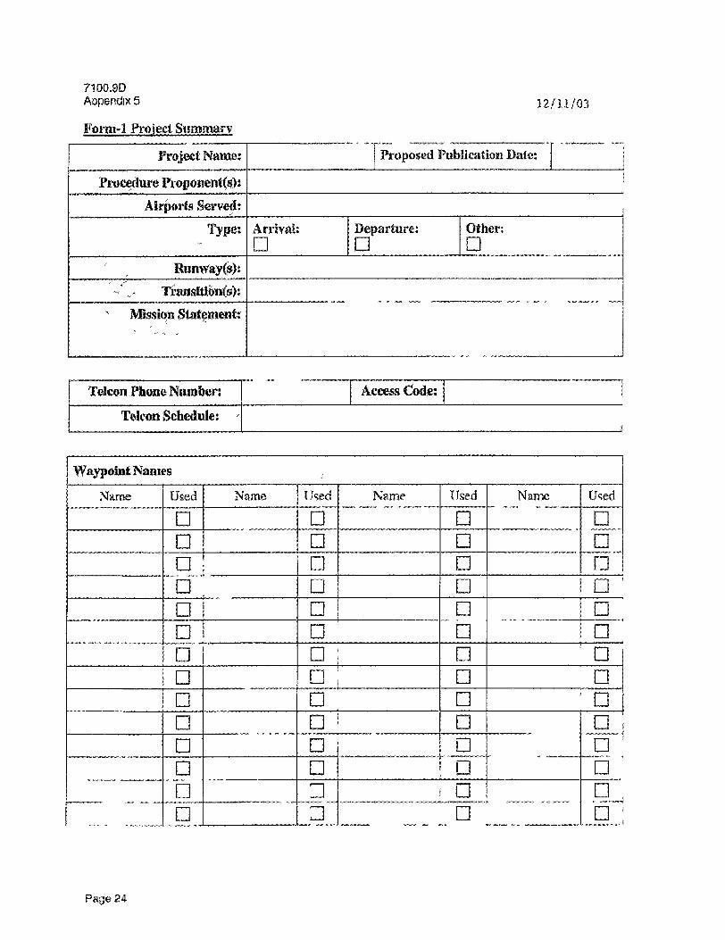
bull
bull
bull bull
bull
71009D Aopendix 5
Forni-1 Project Summary
Project Name
Prtwedttre PrcopypregHeiit(s)s Airports Served
Typet Arrival
121103
Proposed Publication Batreg
Departure Other
r RiinwaKsect)J
TraiwioiiCs) Mission Siateiiienfe
mdash mdash mdash
Tekraquon Phone Numbers TelcltMt Schedule gt
Access Code 1 (
Waypoint Names
Name Used Name Used Name Used Name Used
D D D D
j
bull
D bull D Q ( bull n
rr i bull 1 bull n bdquo bdquo bdquo _ _ _
bull bull i n bull i I D bull bull D
i1 n bull bull bull bull i L J laquo
bull bull gt
D D 1D D D bull
bull mdash mdash mdash mdash bull -g- n r i
Page 24
121103
Form-2 Guideline Item Index
71008D Appendix 5
(tem v
Start Date
Status
i Kickoff Meeting
l Adapt TARGETS
Reserve Waypoint Names
Design the Procedure
Simulator Evaluation
ji
Working Gioup Review of Procedtre
Process Decision
lt
i
Procedure Documentation i
Automation mdash mdash mdash -bull mdash shy - shy
_ _ _
s Envhunmental Review j
Adv i se Industry of Project k
Development
1
1 AVN Flight Check
Video Maps mdash - shy
|
Training and Notification
Process Verification _ _
Lead Operator Flight Trial 5
Publish Procedure foi Pubhc Use Post Procedure Implementation Analysts
Page 25
710090 Appendix 5 171101
Forni-3 Project Action Items
Action Item Assigned To Assign Date
Closed Bate Notes
1
-
i
i
i
Pago 26
121103 71009D Appendix 5
Form-4 Workimi Group Contact List Name Organization Phone Number E-Mail
i
f i
- _ _ bdquo _ bdquo bdquo bdquo _ _
_
I f
i i
i
Psgo 7
Form-5 RNAV Flight Simulator Worlcsheet
( 1) Operator Name See attachment for completion mstrcctions
(21 Procedure Name m Date
(4) Jype feg CARIZF] (5) LNAV VNAV lineags Point
(6) FMSGPS Manufacturer () FMSOPS Software Version
(g) Initial Wind Setup 10 K-TS or Maximum allowable tail wind on surface jncreasing to 30 KTS at 1000 feet then iacflampasebv 10 KTSevery 2000 feet until teachjaaSQ KTS
i^tSM R e a l Run 2 Rmt3 Rim4 Run S
(9) Ruiiwayaiid En Route Transition Flown
(10) Max allowable Takeoff Weight of Aircraft fli) Takeoff Throat used
Q2)Max SiirfaceTailwirid (SID only)
f3) Temperatuie (ISA)
(14) Type ofGujdariee
(15) Navigation Source
(16) Other
pound12LReinarks
(IS) Completed Bv (19) Phone Number
(20) Attach a print out of the FAA kg-type coding and a copy of the lateral aodjverjrical tiackromihc jproceduraflowR
O
Forrolaquo5 RNAV Flight Simutator Worksheet fContintied)
(21 Procedure Maine Run Complete tor Each Roe
K3
(21)WayfxjwitName - (221 Altitude - bull (23) Airsrx^JClcoimdsjaed
bull -- (M) Turn AnticioatioTt
Distance bull 1251 Wind
mdash mdash - shy mdash shy ~ shy
bdquo bdquo bdquo _ _ _ _ _ _ raquo _ _ bdquo _
mdashmdash-mdashmdashbull shy
1
j
mdash bull -
mdash - shy - - mdash _
i
i1 I
i
I
|
1
gt ^
tn
Instructions for Completing RNAV Flight Simulator Worksheet xr
w
J)
2)
1 3)
Rntert|ieoperator name
Enter the RNAV procedure name fep PAIGW RNAV five departure) Enterlhe date simxiladons were accomplished
1 sect
x
P
bullbullbull-~lt- -bull- laquo bull - trade ^
l 4) Enter the aircraft type and equipment suffix (eg CARJF 5) For standard instrument departures (SID) enter the point at which LNAVVNAV is engaged (as specified in operator operations manual)
6 Ejitet the FMS or GPS stand-alone manufacturers narraquog fejeHoncYweHSiniths1eK) 7) Enter the PMS or GPS stand-alone s o ft ware version 8) Use an in-tlieht tailwind of 30 KTS at 1 QQQ feet arid increase by 10 KTS every 2000 feet until reaching 80-KT tail wind (record wind u ed^mJMock aSJ
(Additionally for SIPs use crosm^dhearing opposite of first turn) 9) Enter the runway and en route transition flown 0) Enter tha takeoff weight - fly procedures at maximum allowable takeoff weight 11) Enter the takeoff thrust used - list either reduced or maximum takeoff settingiiBedXrrjgx^pwablebdquogervcojdx|ioas 12) Enter the surface tailwind - initiate takeoff with10-KT tailwind component 13) Enter the TSAiemperature - fly the procedure at average max summer temperature for the airport and use indicated climb gradients
14) Enter the type cf flight guidance used Tha preferred flight guidance is the autopilot List other if used fee flight director or CDR 15) Enter the navigation sensorreferenced whileflying the procedure (eaGPSsIRUDMEDME DMEDME) 16) Enter any working group specified conditions (eg crosswittd componerit) 1T) Enter any reoiarll about Aferarecediire^ W) Enter the name of poison completing the form 19) Enter an appfopriateeoMact phone number of the person conipleting form 20) Attach a print out of the leg type coding and lateral vertical trackforSMhlup fjown
21) bnttfi the name of WAypo t passed bv the aircraft (complete sheet for each ran completed)
22) Enter the aircraft altitude pacing the waypoint listed In box 21 23) bull nter the aircraft airground speed passing the waypoint listed in box 21 24) Enter the aircraft ten anticipation distance passing the waypoint listed in box 21 25) Enter the wind direction and veloc|tynassirig the waypomt listed in box21
o
121103 71009D Aapendix 5
Form-6 Industry Notification
Airport 1 Procedure Type I STAR [ J SID bull Other bull
Procedure Name j Expected Publication Date
Procedure BescrlpttenComrttente
Quick Align Waypoint Data (list name latitudelongitude)
Distribution Lists
j AOPA n ATA D NBAA f l RAA imdash
Other H
Note Attach TARGETS distribution package with this notification
Page 31
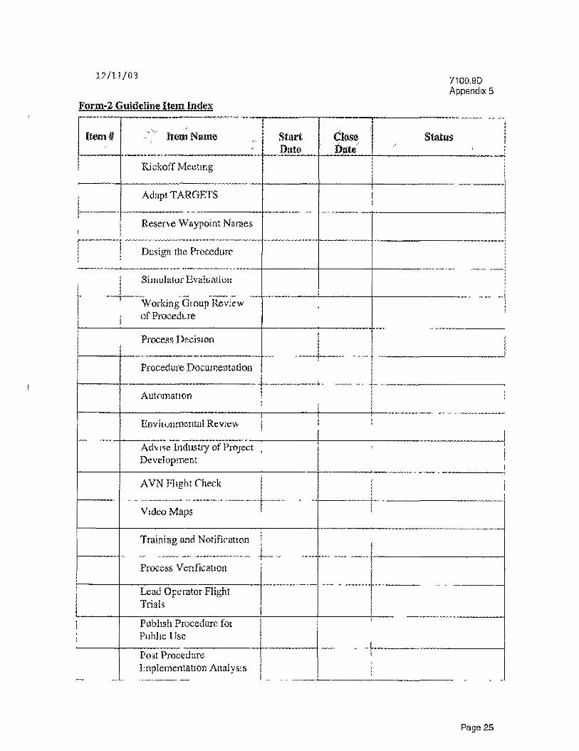
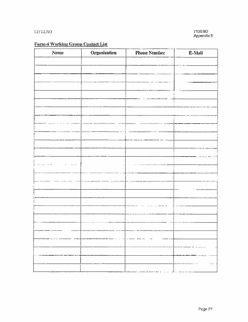
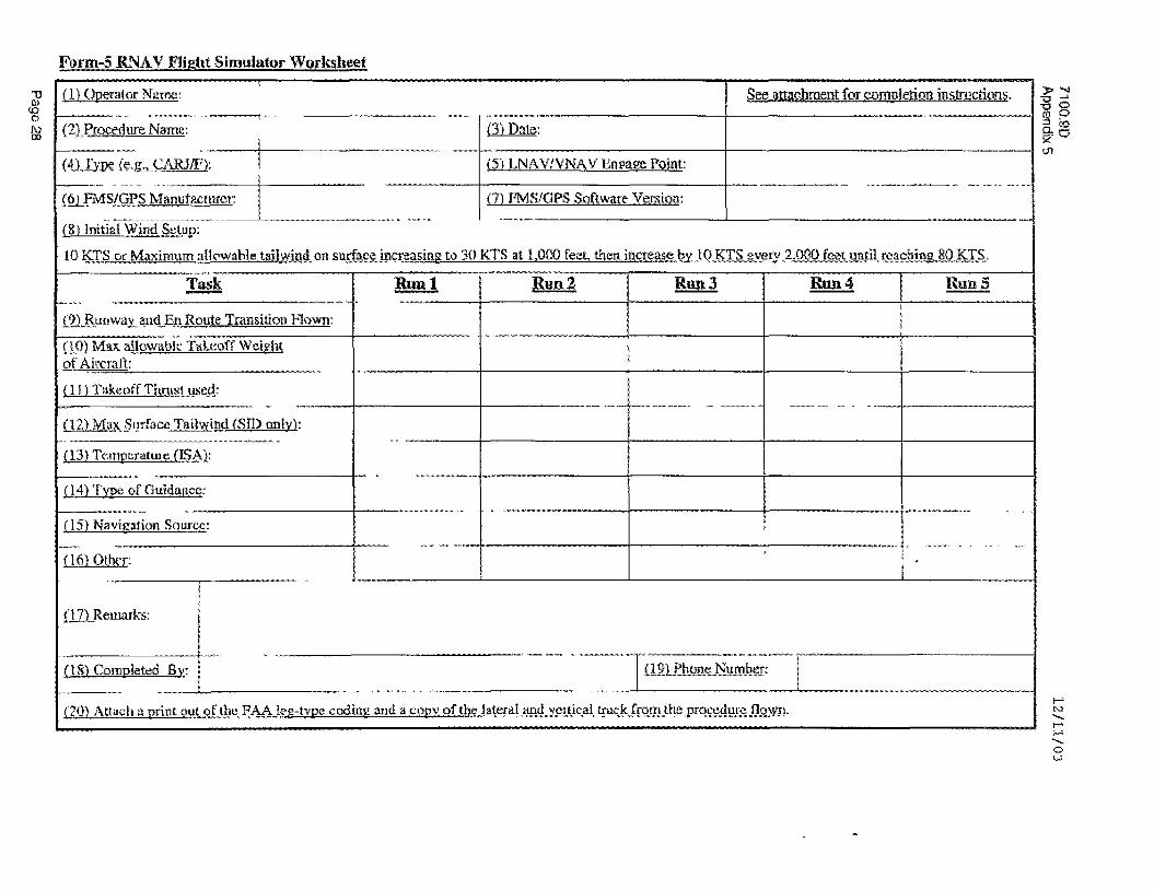
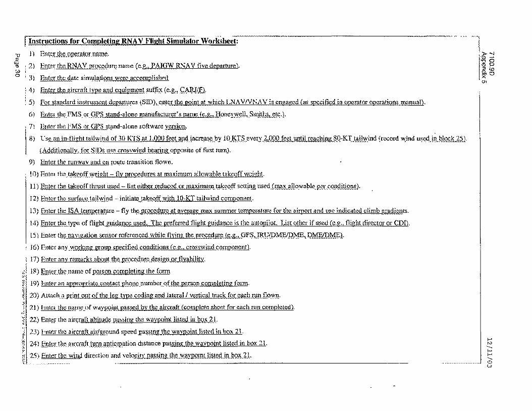