Embed Size (px)
Citation preview
Excellence Pump Industry Co., Ltd.
Installation and Operating Manual
The EHM(R) Slurry Pump
2
SAFETY INFORMATION
The following safety information relating to pump operation and maintenance should be carefully observed, and correct procedures followed, to avoid injuries to personnel, and damage to equipment. All statutory requirements relating to this equipment must be complied with at all times.
DO NOT APPLY HEAT TO THE IMPELLER HUB OR INLET EYE TO ASSIST
IMPELLER REMOVAL. APPLICATION OF HEAT MAY RESULT IN SHATTERING OF
THE IMPELLER, RESULTING IN INJURY OR EQUIPMENT DAMAGE.
DO NOT OPERATE THE PUMP FOR AN EXTENDED TIME WITH ZERO OR VERY
LOW FLOWRATE. FAILURE TO OBSERVE THIS WARNING COULD RESULT IN
OVERHEATING OF THE PUMP, AND VAPORISATION OF THE PUMPED FLUID, WITH
GENERATION OF VERY HIGH PRESSURES. SERIOUS INJURY TO PERSONNEL OR
DAMAGE TO EQUIPMENT MAY RESULT FROM SUCH ACTION.
CHECK DRIVE MOTOR ROTATION PRIOR TO FITTING OF DRIVE BELTS OR
COUPLINGS. INCORRECT MOTOR ROTATION MAY CAUSE PERSONNEL INJURY OR
EQUIPMENT DAMAGE.
DO NOT FEED VERY HOT OR VERY COLD FLUID INTO A PUMP AT AMBIENT
TEMPERATURE. THERMAL SHOCK MAY RESULT IN FRACTURE OF PUMP WET-END
PARTS.
WHERE AUXILIARY EQUIPMENT IS ASSOCIATED WITH A PUMP. (e.g. MOTORS,
DRIVE BELTS, DRIVE COUPLINGS, SPEED REDUCERS, VARIABLE SPEED DRIVES,
ETC), ALL RELEVANT INSTRUCTION MANUALS SHOULD BE CONSULTED, AND
RECOMMENDED PROCEDURES IMPLEMENTED, DURING INSTALLATION,
OPERATION AND MAINTENANCE OF THE PUMP SYSTEM.
THE PUMP SHOULD NOT TURN UNDER LOW OR ZERO CAPACITY FOR LONG. OTHERWISE THE PUMP MAY VIBRATE AND THE PUMP FLUID MAY VAPORIZE, WHICH MAY CREATE HAZARDS FOR PERSONNEL OR PROPERTY OR LEAD TO PREMATURE FAILURE OF THE PUMP. DO NOT WORK ON THE PUMP SET UNTIL THE ELECTRICITY SUPPLY HAS BEEN DISCONNECTED COMPLETELY AS THE PUMP IS A ROTARY OBJECT. IT MAY CAUSE ACCIDENTS FOR PERSONNEL OTHERWISE! WHEN THE PUMP IS IN OPERATION, HANDS SHOULD NOT GET INTO OR REMOVE THE PROTECTIVE SHIELD OF THE PUMP. IT MAY CAUSE ACCIDENTS FOR PERSONNEL OTHERWISE!
3
Contents
1. General…………………………………………………………… (4)
2. Structure………………………………………………………… (5)
3. Assembly ……………………………………………………… (7)
4. Operation……………………………………………………… (13)
5. Maintenance……………………………………………………… (17)
6. Possible problems and solutions………………………………… (19)
4
1. General
The horizontal slurry pump is a cantilevered centrifugal slurry pump. It is suitable for carrying corrosive or abrasive slurry. It is widely used in metallurgy, mining, the oil industry, the petrochemical industry, the coal industry, power generation, transport, construction, public service, et cetera. Types EHM, the wetted components of this pump are made of high Chromium, 27%. The frame plate, cover plate and rotary parts are interchangeable with that of Types EHR. It is suitable for carrying slurry with fine particles and corrosive slurry, to some degree.
5
2. Structure
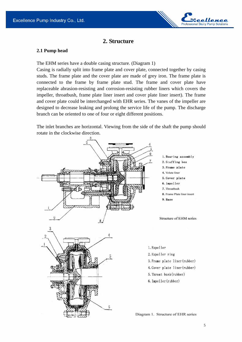
2.1 Pump head The EHM series have a double casing structure. (Diagram 1) Casing is radially split into frame plate and cover plate, connected together by casing studs. The frame plate and the cover plate are made of grey iron. The frame plate is connected to the frame by frame plate stud. The frame and cover plate have replaceable abrasion-resisting and corrosion-resisting rubber liners which covers the impeller, throatbush, frame plate liner insert and cover plate liner insert). The frame and cover plate could be interchanged with EHR series. The vanes of the impeller are designed to decrease leaking and prolong the service life of the pump. The discharge branch can be oriented to one of four or eight different positions. The inlet branches are horizontal. Viewing from the side of the shaft the pump should rotate in the clockwise direction.
6
2.2 Shaft seal There are two kinds of seal types: 1. Centrifugal seal, also called Expeller and expeller ring seal. When the pressure at
the inlet mouth is less than 10% of the pressure at the discharge mouth for single-staged pump or the first stage of a multi-staged pump series, centrifugal seal can be adopted. The centrifugal seal has a good sealing effect, which does not require flush water and thus does not dilute the slurry. (NB: Flush water could also be added).
2. Packed gland seal: packed gland seal has a simple structure which makes maintenance easier. But packed gland seal requires flush water. For conditions that make centrifugal seal impossible, packed gland seal is usually adopted.
Rotary parts All horizontal slurry pumps adopt the same model of rotary parts, which include frame and bearing assembly. The rigid shaft has a large diameter and short overhang which does not vibrate or bend even in adverse conditions. Depending on the power required, the bearings could be heavy single row, double row tapered roller bearings, or double row roller bearing, which could withstand great pressure from the axial and radial direction. The bearing is lubricated with grease. Both sides of the bearing housing have end covers, labyrinths, piston rings which would effectively prevent slurry and other dust particles entering the bearings. Then, the bearings have a long service life.
7
3. Assembly
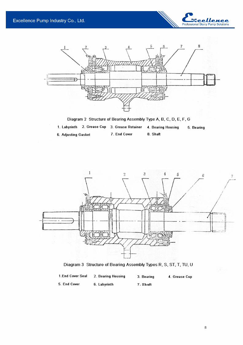
3.1 Bearing Assembly(Diagram 2 & 3) Before assembling, pre-heat the inner race of the bearing to a temperature below 120℃. The inner race must be fixed next to the shaft shoulder or grease retainer. For double row taper roller bearing, the inner ring, outer ring, and lantern ring comes in a set, please do not interchange the components. For bearing assemblies of Type A, B, C, D, E, F, G, single row roller bearing is used. Axial space is ensured by adjusting the gasket at the bearing end cover. The axial space should follow the following table:
Frame Type A B C D E F,G Axial space (mm) 0.05-0.15 0.1-0.2 0.15-0.25 0.18-0.28 0.4-0.6 0.5-0.6
For bearing assembly with type R, S, ST, T, TU, U, the pump uses double row roller bearing on the sides of the shaft. The bearing itself has ensured axial space, thus there is no need for further adjustment. When assembling bearing, a moderate amount of lubricant should be added. Labyrinth ring and labyrinth sleeve is adopted at seal cover end. When assembling bearings, a moderate amount of lubricant should be added. Labyrinth and piston ring are adopted at end cover seal. Please arrange the gaps on the labyrinth rings such that they are not in the same angular position. 2# or 3# lithium-based grease is recommended for shaft lubrication. When installing, the recommended amount of lubricant can be read from the following table:
Frame lubricant(g)
B C D E F G R.RS S.ST T.TU
Driver-side bearing 30 50 100 200 500 1150 200 500 1150
Pump-side bearing 30 5- 100 200 500 1150 400 1000 2300
8
9
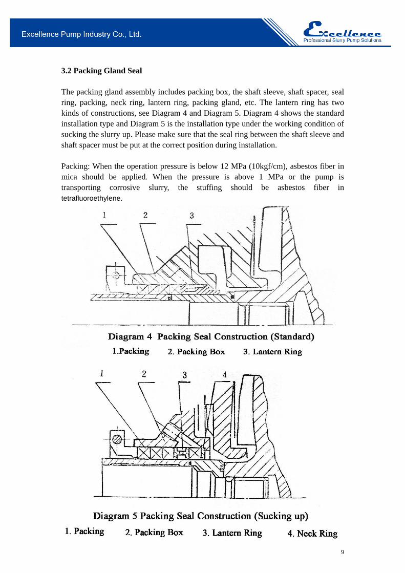
3.2 Packing Gland Seal The packing gland assembly includes packing box, the shaft sleeve, shaft spacer, seal ring, packing, neck ring, lantern ring, packing gland, etc. The lantern ring has two kinds of constructions, see Diagram 4 and Diagram 5. Diagram 4 shows the standard installation type and Diagram 5 is the installation type under the working condition of sucking the slurry up. Please make sure that the seal ring between the shaft sleeve and shaft spacer must be put at the correct position during installation. Packing: When the operation pressure is below 12 MPa (10kgf/cm), asbestos fiber in mica should be applied. When the pressure is above 1 MPa or the pump is transporting corrosive slurry, the stuffing should be asbestos fiber in tetrafluoroethylene.
10
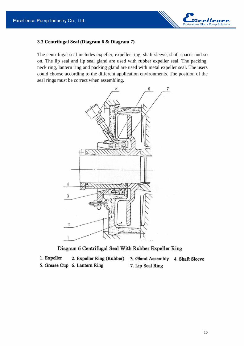
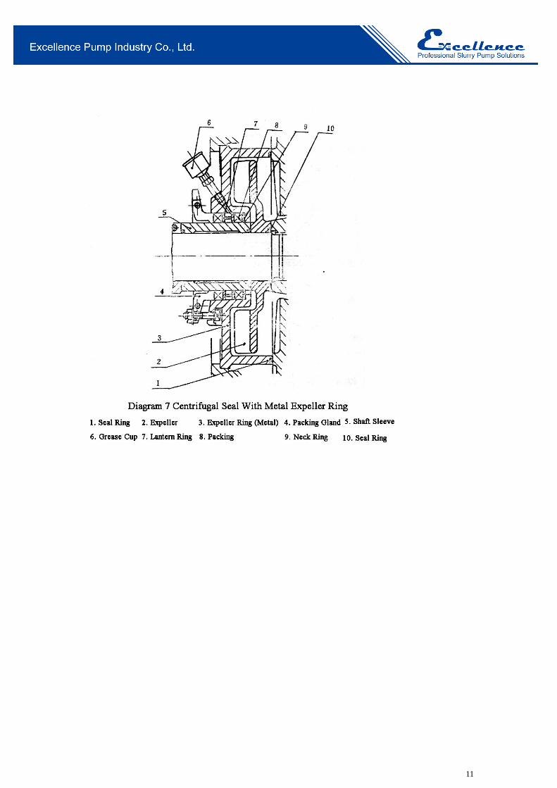
3.3 Centrifugal Seal (Diagram 6 & Diagram 7) The centrifugal seal includes expeller, expeller ring, shaft sleeve, shaft spacer and so on. The lip seal and lip seal gland are used with rubber expeller seal. The packing, neck ring, lantern ring and packing gland are used with metal expeller seal. The users could choose according to the different application environments. The position of the seal rings must be correct when assembling.
11
12
3.4 The Pump Head
1. Put seal ring into the frame plate; install frame plate liner and impeller with locating nut, and then the volute liner.
2. Press the volute liner to the frame plate by means of bolts and clamp board.
3. Install the throatbush and cover plate in turn.
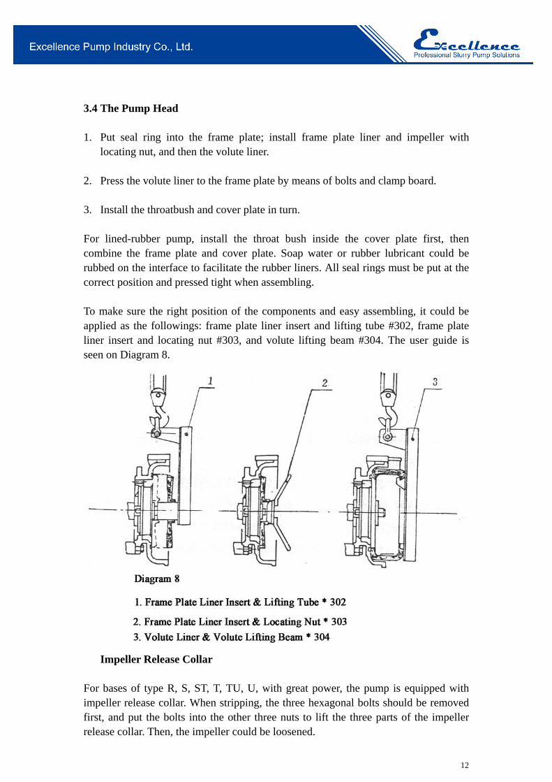
For lined-rubber pump, install the throat bush inside the cover plate first, then combine the frame plate and cover plate. Soap water or rubber lubricant could be rubbed on the interface to facilitate the rubber liners. All seal rings must be put at the correct position and pressed tight when assembling. To make sure the right position of the components and easy assembling, it could be applied as the followings: frame plate liner insert and lifting tube #302, frame plate liner insert and locating nut #303, and volute lifting beam #304. The user guide is seen on Diagram 8.
Impeller Release Collar For bases of type R, S, ST, T, TU, U, with great power, the pump is equipped with impeller release collar. When stripping, the three hexagonal bolts should be removed first, and put the bolts into the other three nuts to lift the three parts of the impeller release collar. Then, the impeller could be loosened.
13
4. Operation
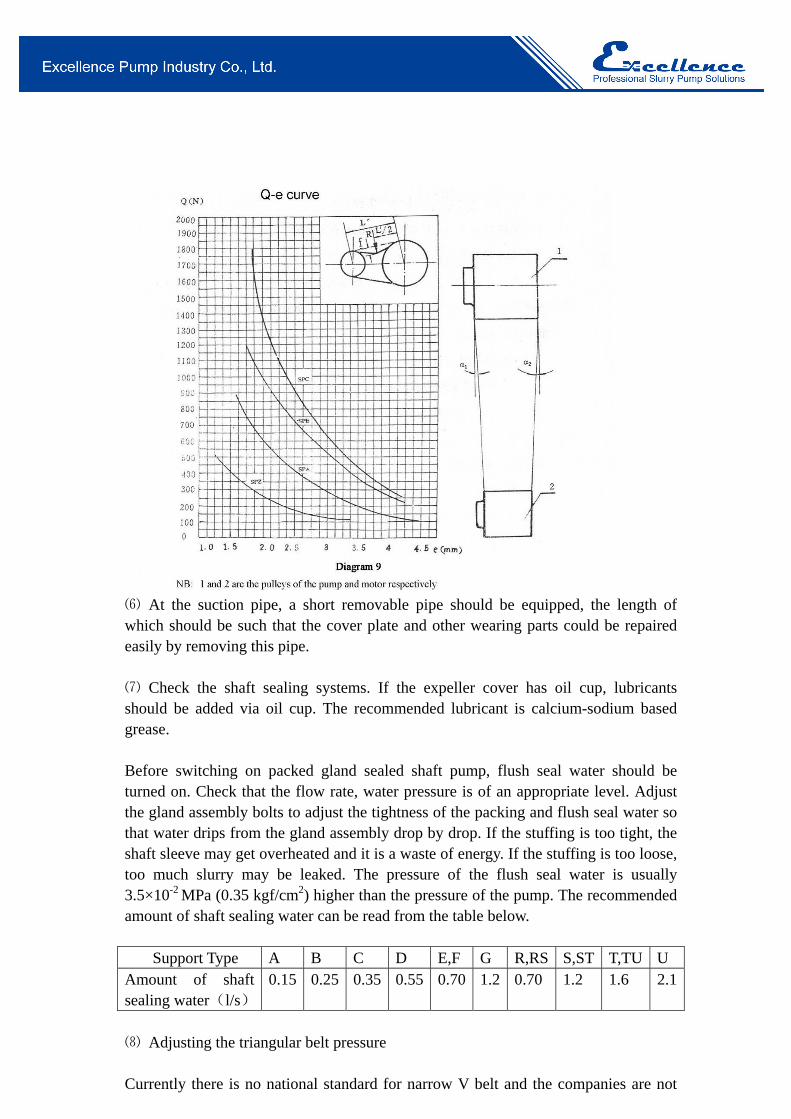
4.1 Starting up Before starting please check the pump by the order listed below. ⑴ The pump should be placed at a secure base which can stand the weight of the pump and minimize vibration. Screw all the foundation bolts tight. ⑵ The pipe and the valve should have separate supports. ⑶ Use hands to turn the shaft to the direction of the rotation of the pump. The shaft should be able to drive the impeller and there should be no friction, otherwise the gap between impeller and frame plate liner and the gap between the impeller and the throat bush should be adjusted. ⑷ Check the direction of rotation of electric motor. Make sure the pump turn in the direction as labeled on the frame plate. Note that the pump must not turn in the reverse direction. Otherwise the impeller may be screwed off the shaft and damage the pump. ⑸ If coupling is used, the shaft of the pump should be exactly co-centric with the shaft of the electric motor. For V-belt drive, the pump shaft and the motor shaft should be parallel. Adjust the position of the groove such that it is perpendicular to the belt, so as to avoid violent vibration and wear and tear. SPA SPB For pulley type SPA and & SPB and matched, SPB SPC the pulleys should be adjusted such that a 1= a 2 as shown in Diagram 9.
14
⑹ At the suction pipe, a short removable pipe should be equipped, the length of which should be such that the cover plate and other wearing parts could be repaired easily by removing this pipe.
⑺ Check the shaft sealing systems. If the expeller cover has oil cup, lubricants should be added via oil cup. The recommended lubricant is calcium-sodium based grease. Before switching on packed gland sealed shaft pump, flush seal water should be turned on. Check that the flow rate, water pressure is of an appropriate level. Adjust the gland assembly bolts to adjust the tightness of the packing and flush seal water so that water drips from the gland assembly drop by drop. If the stuffing is too tight, the shaft sleeve may get overheated and it is a waste of energy. If the stuffing is too loose, too much slurry may be leaked. The pressure of the flush seal water is usually 3.5×10⁻² MPa (0.35 kgf/cm2) higher than the pressure of the pump. The recommended amount of shaft sealing water can be read from the table below. Support Type A B C D E,F G R,RS S,ST T,TU U Amount of shaft sealing water(l/s)
0.15 0.25 0.35 0.55 0.70 1.2 0.70 1.2 1.6 2.1
⑻ Adjusting the triangular belt pressure Currently there is no national standard for narrow V belt and the companies are not
15
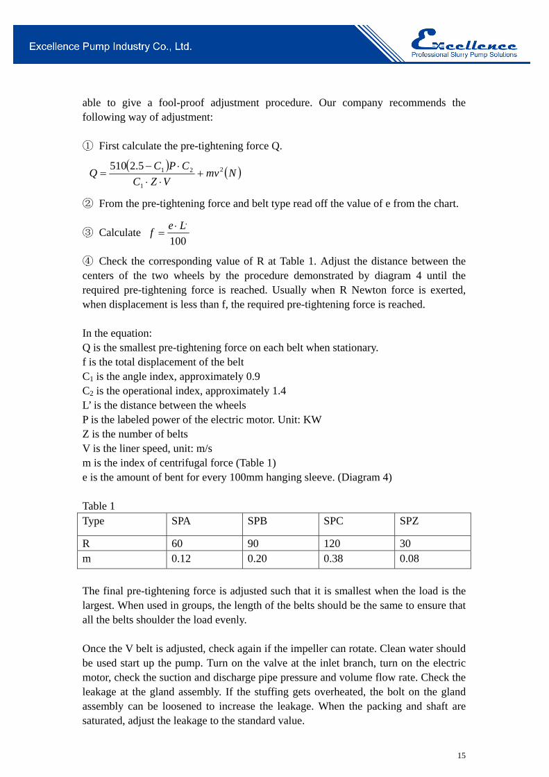
able to give a fool-proof adjustment procedure. Our company recommends the following way of adjustment: ① First calculate the pre-tightening force Q.
Nmv
VZC
CPCQ 2
1
215.2510
② From the pre-tightening force and belt type read off the value of e from the chart.
③ Calculate 100
,Lef
④ Check the corresponding value of R at Table 1. Adjust the distance between the centers of the two wheels by the procedure demonstrated by diagram 4 until the required pre-tightening force is reached. Usually when R Newton force is exerted, when displacement is less than f, the required pre-tightening force is reached. In the equation: Q is the smallest pre-tightening force on each belt when stationary. f is the total displacement of the belt C1 is the angle index, approximately 0.9 C2 is the operational index, approximately 1.4 L’ is the distance between the wheels P is the labeled power of the electric motor. Unit: KW Z is the number of belts V is the liner speed, unit: m/s m is the index of centrifugal force (Table 1) e is the amount of bent for every 100mm hanging sleeve. (Diagram 4) Table 1 Type SPA SPB SPC SPZ
R 60 90 120 30 m 0.12 0.20 0.38 0.08
The final pre-tightening force is adjusted such that it is smallest when the load is the largest. When used in groups, the length of the belts should be the same to ensure that all the belts shoulder the load evenly. Once the V belt is adjusted, check again if the impeller can rotate. Clean water should be used start up the pump. Turn on the valve at the inlet branch, turn on the electric motor, check the suction and discharge pipe pressure and volume flow rate. Check the leakage at the gland assembly. If the stuffing gets overheated, the bolt on the gland assembly can be loosened to increase the leakage. When the packing and shaft are saturated, adjust the leakage to the standard value.
16
4.2 Operation
⑴ When the machine is in operation, check the pressure and volume flow rate of the sealing water regularly, if sealing water is used. Adjust the tightness of sealing cover and replace the stuffing if necessary. Ensure that there is always enough clean water passing over the shaft.
⑵ Check the bearing assembly regularly. If the bearing gets overheated when the operation is started, the pump should be switched off to let the bearing cool down, and then switch on the pump again. When the bearing still gets severely overheated and the temperature keeps rising, the bearing assembly should be stripped and carefully examined to find out the reason. Usually the overheating is caused by excessive lubricant or impure lubricant. The lubrication should be clean and of an appropriate amount. Lubricants should be added regularly.
⑶ The efficiency of the pump decreases as the gap between the impeller and throatbush increases. Thus the impeller should be moved forward regularly to ensure the gap is kept at an appropriate size. When the parts are worn such that the system requirement cannot be met, the wearing parts should be replaced.
4.3 Shutting down
Before shutting down the pump, if possible, the pump should be allowed to transport clean water for a while so as to clean the slurry inside the pump. Then the pump, valve, and sealing water should be stopped in turn.
17
5. Maintenance
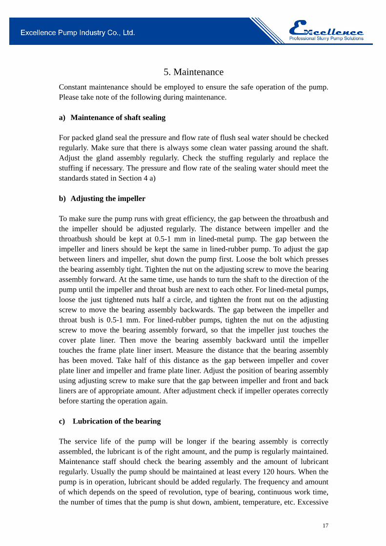
Constant maintenance should be employed to ensure the safe operation of the pump. Please take note of the following during maintenance. a) Maintenance of shaft sealing For packed gland seal the pressure and flow rate of flush seal water should be checked regularly. Make sure that there is always some clean water passing around the shaft. Adjust the gland assembly regularly. Check the stuffing regularly and replace the stuffing if necessary. The pressure and flow rate of the sealing water should meet the standards stated in Section 4 a) b) Adjusting the impeller To make sure the pump runs with great efficiency, the gap between the throatbush and the impeller should be adjusted regularly. The distance between impeller and the throatbush should be kept at 0.5-1 mm in lined-metal pump. The gap between the impeller and liners should be kept the same in lined-rubber pump. To adjust the gap between liners and impeller, shut down the pump first. Loose the bolt which presses the bearing assembly tight. Tighten the nut on the adjusting screw to move the bearing assembly forward. At the same time, use hands to turn the shaft to the direction of the pump until the impeller and throat bush are next to each other. For lined-metal pumps, loose the just tightened nuts half a circle, and tighten the front nut on the adjusting screw to move the bearing assembly backwards. The gap between the impeller and throat bush is 0.5-1 mm. For lined-rubber pumps, tighten the nut on the adjusting screw to move the bearing assembly forward, so that the impeller just touches the cover plate liner. Then move the bearing assembly backward until the impeller touches the frame plate liner insert. Measure the distance that the bearing assembly has been moved. Take half of this distance as the gap between impeller and cover plate liner and impeller and frame plate liner. Adjust the position of bearing assembly using adjusting screw to make sure that the gap between impeller and front and back liners are of appropriate amount. After adjustment check if impeller operates correctly before starting the operation again. c) Lubrication of the bearing The service life of the pump will be longer if the bearing assembly is correctly assembled, the lubricant is of the right amount, and the pump is regularly maintained. Maintenance staff should check the bearing assembly and the amount of lubricant regularly. Usually the pump should be maintained at least every 120 hours. When the pump is in operation, lubricant should be added regularly. The frequency and amount of which depends on the speed of revolution, type of bearing, continuous work time, the number of times that the pump is shut down, ambient, temperature, etc. Excessive
18
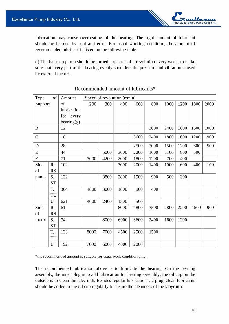
lubrication may cause overheating of the bearing. The right amount of lubricant should be learned by trial and error. For usual working condition, the amount of recommended lubricant is listed on the following table. d) The back-up pump should be turned a quarter of a revolution every week, to make sure that every part of the bearing evenly shoulders the pressure and vibration caused by external factors.
Recommended amount of lubricants*
Type of Support
Amount of lubrication for every bearing(g)
Speed of revolution (r/min) 200 300 400 600 800 1000 1200 1800 2000
B 12 3000 2400 1800 1500 1000
C 18 3600 2400 1800 1600 1200 900
D 28 2500 2000 1500 1200 800 500
E 44 5000 3600 2200 1600 1100 800 500F 71 7000 4200 2000 1800 1200 700 400 Side of pump
R, RS
102 3000 2000 1400 1000 600 400 100
S, ST
132 3800 2800 1500 900 500 300
T, TU
304 4800 3000 1800 900 400
U 621 4000 2400 1500 500 Side of motor
R, RS
61 8000 4800 3500 2800 2200 1500 900
S, ST
74 8000 6000 3600 2400 1600 1200
T, TU
133 8000 7000 4500 2500 1500
U 192 7000 6000 4000 2000
*the recommended amount is suitable for usual work condition only.
The recommended lubrication above is to lubricate the bearing. On the bearing assembly, the inner plug is to add lubrication for bearing assembly; the oil cup on the outside is to clean the labyrinth. Besides regular lubrication via plug, clean lubricants should be added to the oil cup regularly to ensure the cleanness of the labyrinth.
19
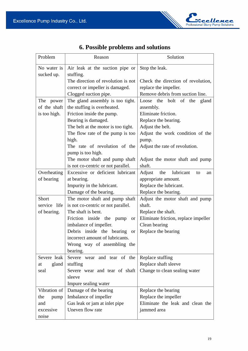
6. Possible problems and solutions
Problem Reason Solution
No water is sucked up.
Air leak at the suction pipe or stuffing. The direction of revolution is not correct or impeller is damaged. Clogged suction pipe.
Stop the leak. Check the direction of revolution, replace the impeller. Remove debris from suction line.
The power of the shaft is too high.
The gland assembly is too tight. the stuffing is overheated. Friction inside the pump. Bearing is damaged. The belt at the motor is too tight. The flow rate of the pump is too high. The rate of revolution of the pump is too high. The motor shaft and pump shaft is not co-centric or not parallel.
Loose the bolt of the gland assembly. Eliminate friction. Replace the bearing. Adjust the belt. Adjust the work condition of the pump. Adjust the rate of revolution. Adjust the motor shaft and pump shaft.
Overheating of bearing
Excessive or deficient lubricant at bearing. Impurity in the lubricant. Damage of the bearing.
Adjust the lubricant to an appropriate amount. Replace the lubricant. Replace the bearing.
Short service life of bearing.
The motor shaft and pump shaft is not co-centric or not parallel. The shaft is bent. Friction inside the pump or imbalance of impeller. Debris inside the bearing or incorrect amount of lubricants. Wrong way of assembling the bearing.
Adjust the motor shaft and pump shaft. Replace the shaft. Eliminate friction, replace impellerClean bearing Replace the bearing
Severe leak at gland seal
Severe wear and tear of the stuffing Severe wear and tear of shaft sleeve Impure sealing water
Replace stuffing Replace shaft sleeve Change to clean sealing water
Vibration of the pump and excessive noise
Damage of the bearing Imbalance of impeller Gas leak or jam at inlet pipe Uneven flow rate
Replace the bearing Replace the impeller Eliminate the leak and clean the jammed area
20
Headquarter:
Add: No.368, Xinshi North Road, Shijiazhuang, Hebei, China 050091.
Beijing Branch:
Add: No.78, East 4th Ring Middle Road, Beijing, China 100124.
Tel: +86-10-81107022 Fax: +86-10-81107016
For inquiries, please send your emails to [email protected]
For customer service, please send your emails to [email protected]