Embed Size (px)
Citation preview
INSTRUCTION MANUAL
Model 701C
Follow Stimulator
March 16, 2010, Revision 0
Copyright 2009-2010 Aurora Scientific Inc.
Aurora Scientific Inc.
360 Industrial Parkway S., Unit 4
Aurora, Ontario, Canada L4G 3V7
Tel: 1-905-727-5161
Toll Free: 1-877-878-4784
Fax: 1-905-713-6882
Email: [email protected]
Web Site: www.AuroraScientific.com
INSTRUCTION MANUAL PAGE 1 OF 15 MODEL 701C
FOLLOW STIMULATOR REV. 0
File: 701C.Manual.doc Aurora Scientific Inc., 2009-2010
Table of Contents
Table of Contents ................................................................................................................. 1
1.0 Safety ............................................................................................................................. 3
2.0 Introduction .................................................................................................................... 4
3.0 Specifications ................................................................................................................. 7
4.0 Operating Instructions .................................................................................................... 8
4.1 Output Cabling ........................................................................................................... 8
4.2 Load Interconnection .................................................................................................. 8
4.3 Controls ...................................................................................................................... 8
4.4 Optional Monitor Connectors available on the model 701C-M ............................... 10
4.5 Power-up Procedures ................................................................................................ 11
5.0 Troubleshooting ........................................................................................................... 13
5.1 Troubleshooting Procedure ....................................................................................... 13
5.2 Technical Assistance ................................................................................................ 14
6.0 Warranty ....................................................................................................................... 15
7. 0 Terms and Conditions for Returning Equipment ........................................................ 16
Drawings ............................................................................................................................ 17
INSTRUCTION MANUAL PAGE 2 OF 15 MODEL 701C
FOLLOW STIMULATOR REV. 0
File: 701C.Manual.doc Aurora Scientific Inc., 2009-2010
*** WARNING ***
SAFE OPERATING PROCEDURES AND PROPER USE OF THE
EQUIPMENT ARE THE RESPONSIBILITY OF THE
USER OF THIS SYSTEM.
Aurora Scientific Inc. provides information on its
products and associated hazards, but it assumes no
responsibility for the after-sale operation and safety practices.
ALL PERSONNEL WHO WORK WITH OR ARE EXPOSED
TO THIS EQUIPMENT MUST TAKE PRECAUTIONS TO PROTECT
THEMSELVES AGAINST POSSIBLE SERIOUS
AND/OR FATAL BODILY INJURY.
NOT FOR HUMAN USE.
INSTRUCTION MANUAL PAGE 3 OF 15 MODEL 701C
FOLLOW STIMULATOR REV. 0
File: 701C.Manual.doc Aurora Scientific Inc., 2009-2010
1.0 Safety
The high voltage/high current nature of this device dictates the use of caution when operating
or servicing this equipment. OBSERVE ALL SAFETY PRECAUTIONS LISTED BELOW.
FAILURE TO DO SO COULD RESULT IN SERIOUS INJURY.
Precautions
1) The 701C stimulator should be serviced only by personnel experienced in high
voltage pulsed power systems.
2) Service personnel should be instructed to observe all safety precautions as stated
in the operating instructions, and those safety precautions standard to the high
voltage pulsed power community. Failure to do so could result in serious injury.
3) Do not handle the load or terminations, or remove the input or output cables,
while the stimulator is in operation. Ensure that the high voltage power supplies
have fully discharged before handling the load. Failure to observe these
precautions can result in potential electric shock to personnel, arcing, and damage
to the connectors and system.
4) The stimulator contains reference planes that are elevated to the potential of the
output pulse. Extreme caution should be exercised when servicing the equipment.
5) Pulsed power systems are capable of random triggering via transients and
therefore when the stimulator is turned on, or high voltage is present in the
module, assume it is possible to get a pulse on the output cable.
INSTRUCTION MANUAL PAGE 4 OF 15 MODEL 701C
FOLLOW STIMULATOR REV. 0
File: 701C.Manual.doc Aurora Scientific Inc., 2009-2010
2.0 Introduction
The model 701C is a high power, bi-polar, pulse stimulator that can provide positive,
negative or alternating voltage pulses of up to 80 volts at up to 1 ampere of current. The high
power output of the unit is available at the front panel BNC connector labeled Output Pulses.
For safety the outer sleeve of this connector and the outer ground braid of the co-ax cables
you connect to it are at chassis ground.
The stimulator can be configured to operate in constant current or constant voltage
modes. In constant current mode the output voltage is varied to obtain the desired current. In
constant voltage mode the output current varies to keep the voltage constant.
In constant current mode the 701C can provide output currents from 0.4 milliamp
(mA) to 1000 milliamps (1 amp) in three ranges. The output current is set using the Range
switch in combination with the Adjust potentiometer both of which are located on the front
panel. In constant voltage mode the 701C can provide output voltages from 0 volts to 80
volts. The output voltage is set using the Range switch in combination with the Adjust
potentiometer located on the front panel.
The stimulator includes a Sync Output BNC connector located on the rear panel that
produces a +5V pulse each time an output pulse of either polarity is issued. The start time
and duration of the Sync pulse is identical to that of the Output Pulse. For experiments that
require precise knowledge of the timing of the stimulation pulses we recommend that the
Sync Output be digitized along with main experimental quantities.
With the model 701C-M current and voltage monitor outputs are provided on the rear
panel. These monitors allow the actual output current and voltage of each pulse to be
examined. The current monitor provides an output of 1 V for each 1 A of output current.
Note the current monitor is only active during the pulse so connection of the current monitor
to a voltmeter will provide erroneous readings. If the Output is not connected to a load, the
current monitor will always read zero. The voltage monitor provides an output of 1 V for
each 10 V of output voltage.
The 701C can be used as a constant current or a constant voltage stimulator. The
setting of the Range switch determines the operating mode and range. The available current
ranges are 10mA, 100mA and 1A full scale. The available voltage ranges are 20V and 80V
full scale. Within any selected range of either current or voltage the Adjust potentiometer is
used to set the level within that range. The Adjust potentiometer is a ten turn control with a
turns counting dial that provides precise control within the selected range. To operate in
constant current mode set the Range switch to one of the three current modes and then set the
current with the Adjust potentiometer. The stimulator will then vary the voltage up to the
maximum of 80 volts in order to maintain the current at the set level. To operate in constant
voltage mode set the Range switch to one of the two voltage ranges and then set the desired
INSTRUCTION MANUAL PAGE 5 OF 15 MODEL 701C
FOLLOW STIMULATOR REV. 0
File: 701C.Manual.doc Aurora Scientific Inc., 2009-2010
voltage with the Adjust potentiometer. The stimulator will then vary the current up to the
maximum of 1 ampere in order to maintain the voltage at the set level.
The 701C Follow Stimulator was designed to follow the pulse pattern produced by a
computer or other device. The trigger signal is input through the Pulse Trigger BNC located
on the front panel. In operation the stimulator will produce pulses a the Output Pulses
connector, with the current and voltage determined by the Range and Adjust controls,
whenever a trigger pulse is input to the Pulse Trigger connector. The output pulse is active
whenever and for as long as the Pulse Trigger input is above 2 Volts. When controlling the
stimulator with a computer the computer produces trigger signals and the width and
frequency of the stimulator’s output follows the width and frequency of the Pulse Trigger
input.
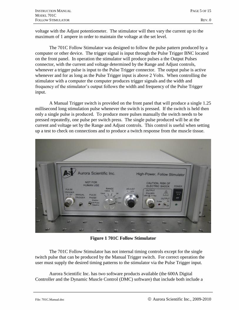
A Manual Trigger switch is provided on the front panel that will produce a single 1.25
millisecond long stimulation pulse whenever the switch is pressed. If the switch is held then
only a single pulse is produced. To produce more pulses manually the switch needs to be
pressed repeatedly, one pulse per switch press. The single pulse produced will be at the
current and voltage set by the Range and Adjust controls. This control is useful when setting
up a test to check on connections and to produce a twitch response from the muscle tissue.
Figure 1 701C Follow Stimulator
The 701C Follow Stimulator has not internal timing controls except for the single
twitch pulse that can be produced by the Manual Trigger switch. For correct operation the
user must supply the desired timing patterns to the stimulator via the Pulse Trigger input.
Aurora Scientific Inc. has two software products available (the 600A Digital
Controller and the Dynamic Muscle Control (DMC) software) that include both include a
INSTRUCTION MANUAL PAGE 6 OF 15 MODEL 701C
FOLLOW STIMULATOR REV. 0
File: 701C.Manual.doc Aurora Scientific Inc., 2009-2010
module that allows the stimulator to be controlled via simple on-screen controls. Precise
timing and synchronization of stimulation and muscle lever control is assured with our
software control programs and a 701C stimulator. Each program provides control of all of
the timing parameters affecting muscle stimulation including: pulse width, pulse frequency,
frequency duration, train, train frequency, and train duration.
A unique feature of the 701C stimulator is the Pulse Phase switch that is used to set
the polarity of the output pulses. The stimulator can be set to generate only positive pulses,
only negative pulses, or pulses of alternating (positive then negative) bi-phase polarity.
These pulses are all referenced to the chassis ground. This means that the outer conductor of
the Output Pulses BNC connector always stays at ground voltage (the same voltage as the
ground pin on the AC input power cable). Operation in the Bi-Phase mode allows the net
current through the muscle bath to be zero. This minimizes corrosion of the electrodes and
the possible release of heavy metals into the bath which could adversely affect the muscle.
For safety purposes an Output control switch is provided next to the Output Pulses
connector. When this switch is off no voltage and current will be available at the Output
Pulses connector regardless of the settings of any of the other controls on the instrument. A
second output control is located on the Range switch. There is a Range switch position
labeled Off that once again will prevent any current or voltage being available at the Output
Pulses connector.
The 701C Follow Stimulator is housed in a 2U (3.4”) high, ½ rack-mount steel and
aluminum enclosure. A ½ rack adapter is available from Aurora Scientific Inc. for mounting
the stimulator in a 19” rack. All controls are located on the front panel along with an LED
that indicates the power is on. A second LED is provided that flashes each time an output
pulse is issued, this provides an easy verification of correct operation.
INSTRUCTION MANUAL PAGE 7 OF 15 MODEL 701C
FOLLOW STIMULATOR REV. 0
File: 701C.Manual.doc Aurora Scientific Inc., 2009-2010
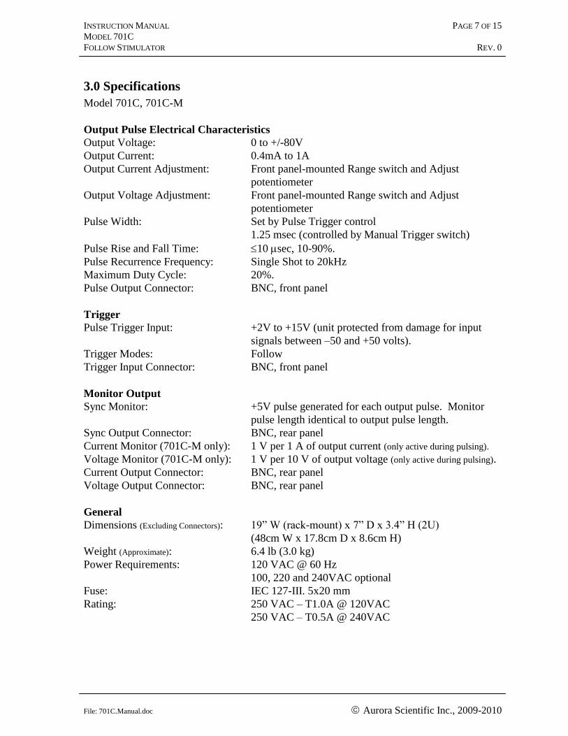
3.0 Specifications
Model 701C, 701C-M
Output Pulse Electrical Characteristics
Output Voltage: 0 to +/-80V
Output Current: 0.4mA to 1A
Output Current Adjustment: Front panel-mounted Range switch and Adjust
potentiometer
Output Voltage Adjustment: Front panel-mounted Range switch and Adjust
potentiometer
Pulse Width: Set by Pulse Trigger control
1.25 msec (controlled by Manual Trigger switch)
Pulse Rise and Fall Time: 10 sec, 10-90%.
Pulse Recurrence Frequency: Single Shot to 20kHz
Maximum Duty Cycle: 20%.
Pulse Output Connector: BNC, front panel
Trigger
Pulse Trigger Input: +2V to +15V (unit protected from damage for input
signals between –50 and +50 volts).
Trigger Modes: Follow
Trigger Input Connector: BNC, front panel
Monitor Output
Sync Monitor: +5V pulse generated for each output pulse. Monitor
pulse length identical to output pulse length.
Sync Output Connector: BNC, rear panel
Current Monitor (701C-M only): 1 V per 1 A of output current (only active during pulsing).
Voltage Monitor (701C-M only): 1 V per 10 V of output voltage (only active during pulsing).
Current Output Connector: BNC, rear panel
Voltage Output Connector: BNC, rear panel
General
Dimensions (Excluding Connectors): 19” W (rack-mount) x 7” D x 3.4” H (2U)
(48cm W x 17.8cm D x 8.6cm H)
Weight (Approximate): 6.4 lb (3.0 kg)
Power Requirements: 120 VAC @ 60 Hz
100, 220 and 240VAC optional
Fuse: IEC 127-III. 5x20 mm
Rating: 250 VAC – T1.0A @ 120VAC
250 VAC – T0.5A @ 240VAC
INSTRUCTION MANUAL PAGE 8 OF 15 MODEL 701C
FOLLOW STIMULATOR REV. 0
File: 701C.Manual.doc Aurora Scientific Inc., 2009-2010
4.0 Operating Instructions
*** WARNING ***
1) Do not remove the input or output cables while the stimulator is in operation.
Never intentionally short-circuit the high voltage output of the stimulator. Failure
to observe these precautions can result in potential electric shock to personnel,
arcing, and damage to the connectors and system.
2) Pulsed power systems are capable of random triggering via transients and
therefore when the stimulator is turned on, or high voltage is present in the
chassis, assume it is possible to get a pulse on the output connector.
4.1 Output Cabling
The high current, high voltage output of the 701C is provided at a BNC connector on
the front panel. ASI recommends that the shortest length of cable possible be used to ensure
the fastest possible rise times and best pulse fidelity. A 2 m long standard BNC to BNC
cable was included with the 701C for connecting the output of the stimulator to the load. If
you are using the 701C with Aurora Scientific Inc. apparatus then you will have been
provided with an adapter to connect between the BNC cable and the apparatus. If you are
connecting to some other apparatus or directly to subcutaneous electrodes or wires then
please contact ASI for a list of available adapters.
4.2 Load Interconnection
For optimal waveform fidelity, the ends of the coaxial cable should be connected
directly to the load to minimize interconnection inductance and impedance mismatches. If it
is necessary to use wire leads between the coaxial cable and the load, the leads should be kept
as short as possible. Twisting the leads together (i.e., using twisted pair wire) will reduce the
lead inductance and help to preserve waveform fidelity.
4.3 Controls
The location of all of the controls is shown in Figure 2 on the next page.
The PULSE TRIGGER Input BNC allows remote triggering of the unit. The normal
Pulse Trigger signal should be within the range of +5V to +15V. Signals greater than +2V
will turn the stimulator on and less than +1V will ensure it is off. Damage will not occur for
any signal between –50V and +50V.
INSTRUCTION MANUAL PAGE 9 OF 15 MODEL 701C
FOLLOW STIMULATOR REV. 0
File: 701C.Manual.doc Aurora Scientific Inc., 2009-2010
The MANUAL TRIGGER switch will cause a single 1.25msec long pulse to be issued
from the OUTPUT PULSES connector. The current, voltage and phase of the pulse are all
determined by the front panel controls.
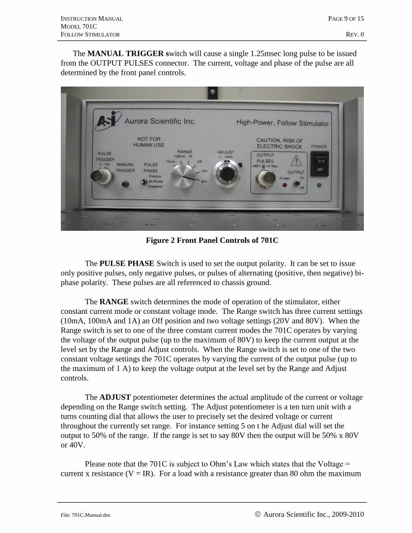
Figure 2 Front Panel Controls of 701C
The PULSE PHASE Switch is used to set the output polarity. It can be set to issue
only positive pulses, only negative pulses, or pulses of alternating (positive, then negative) bi-
phase polarity. These pulses are all referenced to chassis ground.
The RANGE switch determines the mode of operation of the stimulator, either
constant current mode or constant voltage mode. The Range switch has three current settings
(10mA, 100mA and 1A) an Off position and two voltage settings (20V and 80V). When the
Range switch is set to one of the three constant current modes the 701C operates by varying
the voltage of the output pulse (up to the maximum of 80V) to keep the current output at the
level set by the Range and Adjust controls. When the Range switch is set to one of the two
constant voltage settings the 701C operates by varying the current of the output pulse (up to
the maximum of 1 A) to keep the voltage output at the level set by the Range and Adjust
controls.
The ADJUST potentiometer determines the actual amplitude of the current or voltage
depending on the Range switch setting. The Adjust potentiometer is a ten turn unit with a
turns counting dial that allows the user to precisely set the desired voltage or current
throughout the currently set range. For instance setting 5 on t he Adjust dial will set the
output to 50% of the range. If the range is set to say 80V then the output will be 50% x 80V
or 40V.
Please note that the 701C is subject to Ohm’s Law which states that the Voltage =
current x resistance (V = IR). For a load with a resistance greater than 80 ohm the maximum
INSTRUCTION MANUAL PAGE 10 OF 15 MODEL 701C
FOLLOW STIMULATOR REV. 0
File: 701C.Manual.doc Aurora Scientific Inc., 2009-2010
voltage can be obtained but the current will be less than 1 A. The actual current can be
calculated as I = V/R. For example if the bath resistance was 400 ohm then at 80 V the
maximum current that the stimulator can generate will be 80V/400ohm = 0.2A (or 200mA).
For loads with a resistance less than 80 ohm the maximum current of 1 A can be obtained but
the voltage will be less than 80 V. For example if the bath resistance was 60 ohm then at for
a current of 1 A the output voltage will be V=IR=1A x 60ohm = 60V. The 701C has more
than enough current and voltage to fully stimulate muscle tissue in a typical field stimulation
experimental setup.
The OUTPUT PULSES BNC Connector is the high power output of the unit. For
safety, the outer sleeve of this connector and the outer ground braid of the co-ax cables that
you connect to it are at chassis ground.
The Pulses LED lights each time an output pulse is issued as an easy verification of
correct operation. At higher pulse rates the LED will appear to stay on. Note: the LED only
lights when pulses are output. If the OUTPUT switch is set to Off then the LED will not light
even when the 701C is triggered properly.
The OUTPUT switch turns on and off the Output Pulses. This is a physical switch
that disconnects both the central conductor and the outer conductor of the Output Pulses BNC
connector. When the Output switch is off no pulses can be issued from the 701C.
The MAIN POWER Switch applies the AC line power to the transformer-isolated
internal supplies. The unit is protected with a fuse (1A @ 120VAC, 0.5A @ 240VAC)
located in the power entry module on the rear panel of the unit. A spare fuse is included
inside the fuse holder.
The POWER LED lights when the internal supplies are operating properly.
The SYNC OUTPUT BNC connector located on the rear panel will issue a +5V
pulse each time an output pulse of either polarity is issued from the Output Pulses connector.
The length of the Sync pulse is identical to that of the Output Pulse.
4.4 Optional Monitor Connectors available on the model 701C-M
The CURRENT MONITOR BNC allows examination of the actual output current
pulses being delivered by the unit. The output will produce 10 V for each 1 A of output
current. The output polarity is the same as that of the pulses (i.e., for a positive 100 mA
pulse the monitor will show +1.0 V). Note that if the output is not connected to a load, this
current monitor will always read zero. The Current Monitor is only active while the pulses
are being issued, for example, if a 100mA current pulse that is 0.5msec long is issued from
the Output Pulses connector then the Current Monitor will switch to 1V for the 0.5msec that
the pulse is active and then switch back to 0 volts. This means that you can’t determine the
output current by simply connecting a voltmeter to the Current Monitor connector. You will
INSTRUCTION MANUAL PAGE 11 OF 15 MODEL 701C
FOLLOW STIMULATOR REV. 0
File: 701C.Manual.doc Aurora Scientific Inc., 2009-2010
need to connect the Current Monitor either to an oscilloscope or to a PC based data
acquisition system that is acquiring data at a high enough rate to resolve the pulses.
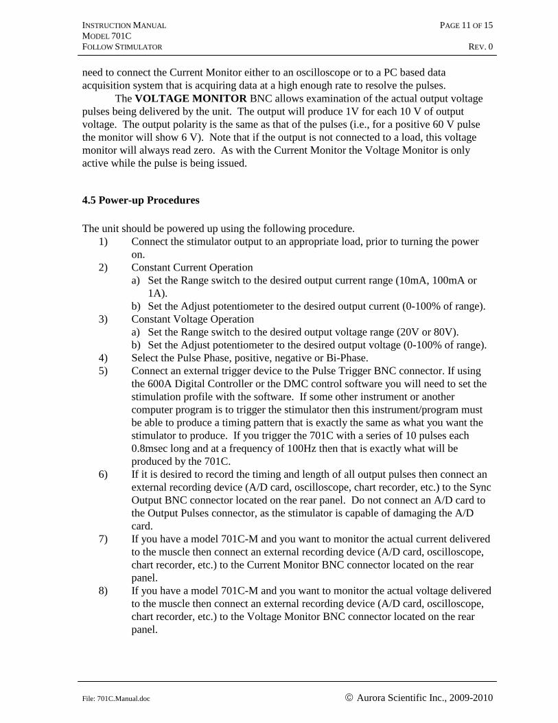
The VOLTAGE MONITOR BNC allows examination of the actual output voltage
pulses being delivered by the unit. The output will produce 1V for each 10 V of output
voltage. The output polarity is the same as that of the pulses (i.e., for a positive 60 V pulse
the monitor will show 6 V). Note that if the output is not connected to a load, this voltage
monitor will always read zero. As with the Current Monitor the Voltage Monitor is only
active while the pulse is being issued.
4.5 Power-up Procedures
The unit should be powered up using the following procedure.
1) Connect the stimulator output to an appropriate load, prior to turning the power
on.
2) Constant Current Operation
a) Set the Range switch to the desired output current range (10mA, 100mA or
1A).
b) Set the Adjust potentiometer to the desired output current (0-100% of range).
3) Constant Voltage Operation
a) Set the Range switch to the desired output voltage range (20V or 80V).
b) Set the Adjust potentiometer to the desired output voltage (0-100% of range).
4) Select the Pulse Phase, positive, negative or Bi-Phase.
5) Connect an external trigger device to the Pulse Trigger BNC connector. If using
the 600A Digital Controller or the DMC control software you will need to set the
stimulation profile with the software. If some other instrument or another
computer program is to trigger the stimulator then this instrument/program must
be able to produce a timing pattern that is exactly the same as what you want the
stimulator to produce. If you trigger the 701C with a series of 10 pulses each
0.8msec long and at a frequency of 100Hz then that is exactly what will be
produced by the 701C.
6) If it is desired to record the timing and length of all output pulses then connect an
external recording device (A/D card, oscilloscope, chart recorder, etc.) to the Sync
Output BNC connector located on the rear panel. Do not connect an A/D card to
the Output Pulses connector, as the stimulator is capable of damaging the A/D
card.
7) If you have a model 701C-M and you want to monitor the actual current delivered
to the muscle then connect an external recording device (A/D card, oscilloscope,
chart recorder, etc.) to the Current Monitor BNC connector located on the rear
panel.
8) If you have a model 701C-M and you want to monitor the actual voltage delivered
to the muscle then connect an external recording device (A/D card, oscilloscope,
chart recorder, etc.) to the Voltage Monitor BNC connector located on the rear
panel.
INSTRUCTION MANUAL PAGE 12 OF 15 MODEL 701C
FOLLOW STIMULATOR REV. 0
File: 701C.Manual.doc Aurora Scientific Inc., 2009-2010
9) At this point check the Output cabling to the muscle bath to ensure that no
one can come in contact with the central conductor when the unit is
operating. The central conductor of the Output Pulses connector/cable
produces momentary hazardous potentials of up to 80 Volts.
10) Ensure that you are not triggering the unit through the Pulse Trigger connector.
11) Switch on the power switch.
12) Switch on the Pulses switch. At this point the 701C will output pulses if a trigger
is received or if the Manual Trigger switch is pressed.
13) Press the Manual Trigger switch and check that the muscle twitches and that the
Pulses LED lights.
14) If there is no output from the stimulator refer to the Troubleshooting Section of
this manual.
15) Send trigger pulses to the Pulse Trigger connector and check that the Pulses LED
lights and the muscle contracts.
INSTRUCTION MANUAL PAGE 13 OF 15 MODEL 701C
FOLLOW STIMULATOR REV. 0
File: 701C.Manual.doc Aurora Scientific Inc., 2009-2010
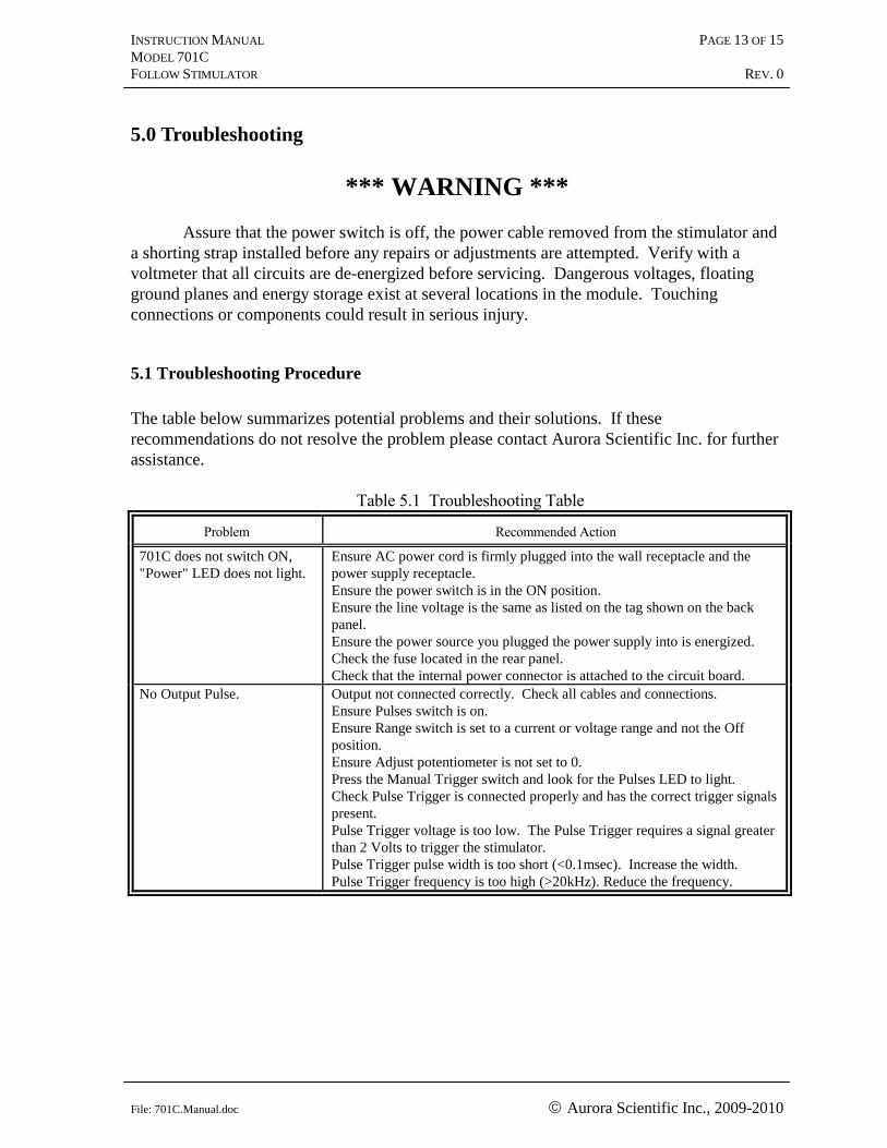
5.0 Troubleshooting
*** WARNING ***
Assure that the power switch is off, the power cable removed from the stimulator and
a shorting strap installed before any repairs or adjustments are attempted. Verify with a
voltmeter that all circuits are de-energized before servicing. Dangerous voltages, floating
ground planes and energy storage exist at several locations in the module. Touching
connections or components could result in serious injury.
5.1 Troubleshooting Procedure
The table below summarizes potential problems and their solutions. If these
recommendations do not resolve the problem please contact Aurora Scientific Inc. for further
assistance.
Table 5.1 Troubleshooting Table
Problem Recommended Action
701C does not switch ON,
"Power" LED does not light.
Ensure AC power cord is firmly plugged into the wall receptacle and the
power supply receptacle.
Ensure the power switch is in the ON position.
Ensure the line voltage is the same as listed on the tag shown on the back
panel.
Ensure the power source you plugged the power supply into is energized.
Check the fuse located in the rear panel.
Check that the internal power connector is attached to the circuit board. No Output Pulse. Output not connected correctly. Check all cables and connections.
Ensure Pulses switch is on.
Ensure Range switch is set to a current or voltage range and not the Off
position.
Ensure Adjust potentiometer is not set to 0.
Press the Manual Trigger switch and look for the Pulses LED to light.
Check Pulse Trigger is connected properly and has the correct trigger signals
present.
Pulse Trigger voltage is too low. The Pulse Trigger requires a signal greater
than 2 Volts to trigger the stimulator.
Pulse Trigger pulse width is too short (<0.1msec). Increase the width.
Pulse Trigger frequency is too high (>20kHz). Reduce the frequency.
INSTRUCTION MANUAL PAGE 14 OF 15 MODEL 701C
FOLLOW STIMULATOR REV. 0
File: 701C.Manual.doc Aurora Scientific Inc., 2009-2010
5.2 Technical Assistance
Technical assistance is available by regular mail, email, phone, or fax. Use the
information below to contact Aurora Scientific Inc.
Address: Aurora Scientific Inc.
Technical Assistance
P.O. Box 2724
Richmond Hill, Ontario, CANADA
L4E 1A7
Phone: 1-905-727-5161
Toll Free: 1-877-878-4784
FAX: 1-905-713-6882
E-mail: [email protected]
Web site: www.AuroraScientific.com
INSTRUCTION MANUAL PAGE 15 OF 15 MODEL 701C
FOLLOW STIMULATOR REV. 0
File: 701C.Manual.doc Aurora Scientific Inc., 2009-2010
6.0 Warranty
The 701C stimulator is warranted to be free of defects in materials and workmanship
for three years from the date of shipment. Aurora Scientific Inc. will repair or replace, at our
option, any part of the system that upon our examination is found to be defective while under
warranty. Obligations under this warranty are limited to repair or replacement of the
instrument. Aurora Scientific Inc. shall not be liable for any other damages of any kind,
including consequential damages, personal injury, or the like. Damage to the system through
misuse will void this warranty. Aurora Scientific Inc. pursues a policy of continual product
development and improvement therefore we reserve the right to change published
specifications without prior notice.
INSTRUCTION MANUAL PAGE 16 OF 15 MODEL 701C
FOLLOW STIMULATOR REV. 0
File: 701C.Manual.doc Aurora Scientific Inc., 2009-2010
7. 0 Terms and Conditions for Returning Equipment
1. Aurora Scientific Inc. will not accept any equipment returned without prior
authorization in the form of a return material authorization number.
1. Please call Customer Service at (905) 727-5161 or toll free at 1-877-878-
4784 to obtain an RMA#. Please specify the product line.
2. Please package equipment properly. Goods that are damaged in shipment are
the responsibility of the shipper.
3. Aurora Scientific, Inc. withholds the right to assess charges for the repair
or replacement of such damaged goods, regardless of warranty status.
4. Warranty repairs will be shipped back to the customer via FedEx. If you require
or request another form of shipment, the cost of such service is your full
responsibility.
5. Aurora Scientific, Inc. will not be responsible for any return or replacement
shipping charges incurred due to an incorrect order placed by the customer.
Return Shipping Address:
Aurora Scientific Inc.
360 Industrial Pkwy. S., Unit 4
Aurora, ON, Canada
L4G 3V7
Attn: RMA Returns
INSTRUCTION MANUAL PAGE 17 OF 15 MODEL 701C
FOLLOW STIMULATOR REV. 0
File: 701C.Manual.doc Aurora Scientific Inc., 2009-2010
Drawings
This section consists of the following drawings:
1) Typical Equipment Setup AS701-G001