Embed Size (px)
Citation preview
700/750/800/850/900/950/1000 704/754/804/854/904/954/1004
Wheeled Tractors
Operation Manual
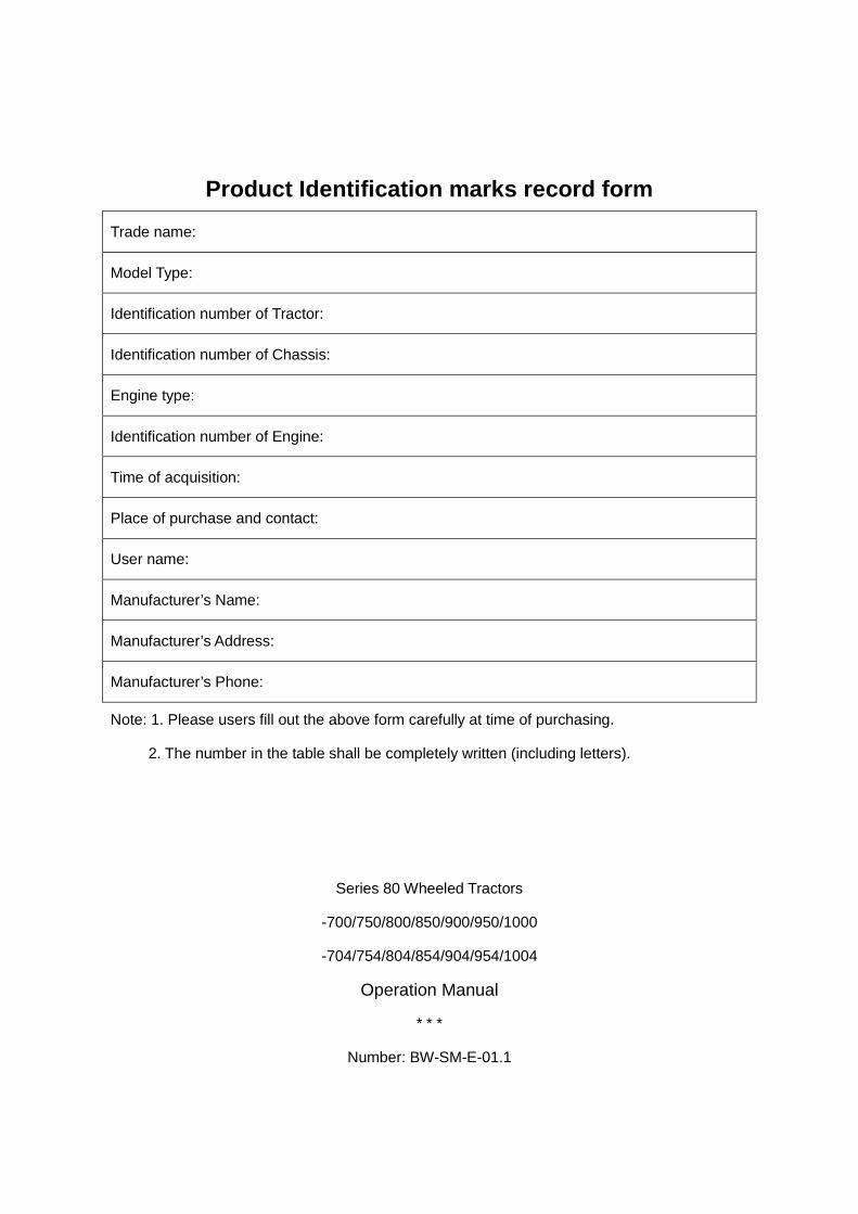
Product Identification marks record form
Trade name:
Model Type:
Identification number of Tractor:
Identification number of Chassis:
Engine type:
Identification number of Engine:
Time of acquisition:
Place of purchase and contact:
User name:
Manufacturer’s Name:
Manufacturer’s Address:
Manufacturer’s Phone:
Note: 1. Please users fill out the above form carefully at time of purchasing.
2. The number in the table shall be completely written (including letters).
Series 80 Wheeled Tractors
-700/750/800/850/900/950/1000
-704/754/804/854/904/954/1004
Operation Manual
* * *
Number: BW-SM-E-01.1
Instruction to Users
Instruction to Users
To honorable users:
Thank you for your belief in our company, and purchasing wheeled tractors of our company.
For the sake of correct, reasonable and effective operation of tractors, please pay attention to the
following information.
1、Before operating the tractor, please read this specification carefully whether you have
experience of driving or not before, because it will help you operate tractor more reasonably and
effectively.
2、For the sake of more economic benefit to you and longer service life of tractor, before
operation, please read carefully this operation specification and operation instruction of matching
engine and agricultural implements, and manipulate and maintain tractor closely as required in
operation specification for the purpose of full use of performance of tractor.
3、Please don’t modify tractors randomly for fear of effect on tractor performance and
unexpected accident, or even the consequence that it is hard to performance guarantee service.
4、Due to great difference in agriculture and soil condition, there are diversified purposes,
parameters, matching agricultural implements and operation efficiency recommended in this
operation specification accordingly. Please users make a choice according to practical conditions.
5、The tractor can be only manipulated, maintained and repaired by persons familiar with
characteristics of tractor, and relevant safe operation knowledge.
6、Drivers must have the license of agricultural vehicles and tractors issued by local traffic
department.
7、Local safety rules and road traffic regulations shall be observed at any time for fear of
unexpected accident.
8、Tractor shall be used in accordance with requirements of this operation specification;
Otherwise, it will probably lead to degradation or failure of tractor.
9、This operation specification is not a quality warranty. Therefore users must not put forward
any requirements on the basis of data, illustration or instruction in the operation specification.
10、The contents said in this operation specification shall be subject to the published product
structure. The contents are subject to change without further notice. Please users pay attention to
it.
11、The products in operation specification accord with the up-to-date standard before the
date of manufacturing.
General Description
General Description The operation specification introduces in detail the safe operation rules, operation precautions,
main technical specification, and methods of wearing, operation, technical maintenance, adjustment, and trouble clearing etc. of series 80 of wheeled tractors for reference of tractor drivers and .service man.
In this operation specification, safety sign indicate important safety information. When
seeing this sign, please pay attention to it to avoid possible injury. Read carefully the following information of the sign and inform other operators of it.
Warning: denote that if not avoided, there will possibly be potential danger, such as
casualties or serious personal injury.
Attention: denote that if not avoided, there will be potential danger such as low and
medium degree personal injury.
Warning: denote that if not avoided, there will possibly be machinery breakdown or
damage to environment. Note: specifying supplementary information. This operation specification is an important part of products. It will be supplied to users along
with tractors. Pleas users keep it properly. In case of incomprehension of part in the operation specification, you can dial service hotline
for consultation.
Intended Use This series of wheeled tractors are multipurpose agricultural wheeled tractors. This type of
tractors is characterized by compact structure, convenience manipulation, flexible steering, great tractive force, wide application, and maintenance and repair convenience etc. if fitted with appropriate agricultural implements, the tractors will be able to conduct plowing, harrowing, sowing and harvesting operations etc. fitted with a trailer, they can be used for agricultural transportation; trailer and tractor mass ratio (specific value between gross mass of trailer and unladen mass of tractor) shall not be more than 3. By power output shaft, they can be coupled with straw returning machine to conduct straw returning operation. They can be also used as motive power of water pump and threshing machine. Please fit agricultural implements correctly as required in this operation specification for the sake of maximum economic benefit. Users shall closely comply with prescribed service, maintenance and repair conditions of manufactory, as well as basic requirements for intended use. The use for other operation will deviate from intended use of tractors.
The tractors can be only operated, maintained and repaired by persons familiar with their characteristics, as well as relevant safe operation knowledge.
Users must comply with the rules against unexpected accident, other safety regulations and road traffic regulations at any time.
Manufactory shall assume no responsibility for degradation of reliability, machinery breakdown or personal injury caused from random modification, or use for the operation going against intended use of tractors.
Contents
Contents 1. Safety Notes– – – – – – – – – – – – – – – – – – – – – – – – – – – – – – – – – – 1
1.1 Safety regulations and notes for use – – – – – – – – – – – – – – – – – – – – – – – – – – 1
1.2 Safety Warning Signs– – – – – – – – – – – – – – – – – – – – – – – – – – – – – – – – – – 7
2. Operation Instruction– – – – – – – – – – – – – – – – – – – – – – – – – – – – – – – – – – 11
2.1 Product description– – – – – – – – – – – – – – – – – – – – – – – – – – – – – – – – – – – – 11
2.2 Operating mechanism and instrument of tractor– – – – – – – – – – – – – – – – – – – – – 11
2.3 Start of engine – – – – – – – – – – – – – – – – – – – – – – – – – – – – – – – – – – – – – – 12
2.4 Start of tractor – – – – – – – – – – – – – – – – – – – – – – – – – – – – – – – – – – – – – – 14
2.5 Steering of tractor– – – – – – – – – – – – – – – – – – – – – – – – – – – – – – – – – – – – 15
2.6 Gear shift of tractor – – – – – – – – – – – – – – – – – – – – – – – – – – – – – – – – – – – 16
2.7 Operation of Differential Lock – – – – – – – – – – – – – – – – – – – – – – – – – – – – – – 17
2.8 Using of Front Drive Axle – – – – – – – – – – – – – – – – – – – – – – – – – – – – – – – – 17
2.9 Braking of the Tractor – – – – – – – – – – – – – – – – – – – – – – – – – – – –– – – –– – – 18
2.10 Stopping of Tractor Stop and Flameout of Engine– – – – – – – – – – – – – – – – – – – 19
2.11 Adjusting of Tread– – – – – – – – – – – – – – – – – – – – – – – – – – – – – – – –– – – – 20
2.12 Using, Dismounting and Mounting of Tyre– – – – – – – – – – – – – – – – – – – – – – – 21
2.13 Using of Balance Weight – – – – – – – – – – – – – – – – – – – – – – – – – – – – – – – – 22
2.14 Adjustment of the Driver’s Seat– – – – – – – – – – – – – – – – – – – – – – – – – – – – – 23
2.15 Covering panels of the Tractor– – – – – – – – – – – – – – – – – – – – – – – – – – – – – 24
2.16 Using of the working device of the tractor– – – – – – – – – – – – – – – – – – – – – – –
24
2.17 Running-in of tractor – – – – – – – – – – – – – – – – – – – – – – – – – – – – – – – – – – 29
2.18 Frequent faults and solutions of tractor – – – – – – – – – – – – – – – – – – – – – – – – 33
3. Accessories, Spare parts and Quick-Wearing Parts – – – – – – – – – – – – – – – 41
3.1 Accessories – – – – – – – – – – – – – – – – – – – – – – – – – – – – – – – – – – – – – – – 41
3.2 Spare parts – – – – – – – – – – – – – – – – – – – – – – – – – – – – – – – – – – – – – – – 42
3.3 Quick-Wearing Parts – – – – – – – – – – – – – – – – – – – – – – – – – – – – – – – – – – 43
Contents
4. Maintenance Instructions – – – – – – – – – – – – – – – – – – – – – – – – – – – – – – – 44
4.1 Technical maintenance rules – – – – – – – – – – – – – – – – – – – – – – – – – – – – – – 44
4.2 Technical maintenance operation – – – – – – – – – – – – – – – – – – – – – – – – – – – – 47
4.3 Adjustment of tractor chassis – – – – – – – – – – – – – – – – – – – – – – – – – – – – – – 53
4.4 Adjustment of hydraulic suspension system– – – – – – – – – – – – – – –– – – – – – – – 58
4.5 Attention for the operation of full hydraulic steering system– – – – – – – – – – – – – – – 59
5. Storage– – – – – – – – – – – – – – – – – – – – – – – – – – – – – – – – – – – – – – – – – – 60
5.1 Reasons for damage of tractor during storage period– – – – – – – – – – – – – – – – – – 60
5.2 Sealing and storing the tractor – – – – – – – – – – – – – – – – – – – – – – – – – – – – – 60
5.3 Service during the period of sealing and storing tractor– – – – – – – – – – – – – – – – – 61
5.4 Unsealing tractor – – – – – – – – – – – – – – – – – – – – – – – – – – – – – – – – – – – – 62
6. Delivery, Acceptance and Transportation – – – – – – – – – – – – – – – – – – – – – 63
6.1 Delivery and acceptance – – – – – – – – – – – – – – – – – – – – – – – – – – – – – – – – 63
6.2 Transportation – – – – – – – – – – – – – – – – – – – – – – – – – – – – – – – – – – – – – – 63
7. Technical Specification – – – – – – – – – – – – – – – – – – – – – – – – – – – – – – – – 64
7.1 Producing Standard – – – – – – – – – – – – – – – – – – – – – – – – – – – – – – – – – – 64
7.2 Product Sign location– – – – – – – – – – – – – – – – – – – – – – – – – – – – – – – – – – 64
7.3 Product Specification– – – – – – – – – – – – – – – – – – – – – – – – – – – – – – – – – – 65
8. Disassembly & Disposal – – – – – – – – – – – – – – – – – – – – – – – – – – – – – – – 74
9. Warranty Items – – – – – – – – – – – – – – – – – – – – – – – – – – – – – – – – – – – – – 75
9.1 Basis of Warranty– – – – – – – – – – – – – – – – – – – – – – – – – – – – – – – – – – – – 75
9.2 Situations beyond warranty– – – – – – – – – – – – – – – – – – – – – – – – – – – – – – – 75
10. Appendix – – – – – – – – – – – – – – – – – – – – – – – – – – – – – – – – – – – – –– – – 76
10.1 Oil and Solution for tractors – – – – – – – – – – – – – – – – – – – – – – – – – – – – – – 76
10.2 Tightening torque table of main bolts and nuts – – – – – – – – – – – – – – – – – – – – – 77
10.3 Matching agricultural implements – – – – – – – – – – – – – – – – – – – – – – – – – – – 78
Safety Precautions
-1-
1. Safety Precautions
1.1 Safety Rules and Precautions for Use
Read Before Operation
1. One must be fully read and understand the use and maintenance instructions and
safety warning signs;
2. Must remember the correct operation and working practices。
Qualified operator
1. When you to operate the machines, must have sufficient judgment;
2. Bodily sensations, drink, lack of sleep, pregnant women, color blindness, and
children under 18 years of age are not allowed to operate the machines;
3. The driver should be trained to obtain a driver's license and acceptance testing
on time;
4. The initial operators should drive at low speed before familiar 。
The driver's clothing requirements
In operation, the driver should wear proper tight-fitting clothes, not allowed to
wear the loose jacket and shirt, and don't wear a tie。
The use of oil-bearing
1. The fuel is combustibles, fireworks is strictly prohibited when use the fuel;
2. Should turn off the engine before filling the fuel;
3. Don't smoking when you refueling or maintenance of fuel systems;
4. When the fuel or oil overflow, use a clean rag cleaned;
5. The quality of fuels and lubricants in strict accordance with the requirements
of the Appendix provides。
Placement of waste oil
1. The oil replaced is waste oil, don’t arbitrarily discarded;
2. The replaced battery acid will pollute the environment, don’t arbitrarily
fly-tips。

Safety Precautions
-2-
When the pipeline leak
If high pressure oil leak from the pipeline, don't use hand to direct touch;You can
use the thick paper or slab to detect the site of the possible leakage。
Emergency disposal
1. When brake failure happens, should stabilize the steering wheel to reach a safe
place , then, immediately turn off, turn off the engine;
2. Failure of the steering wheel, should immediately brake, then turn off the engine;
3. When the machine catch fire, should immediately turn off the engine。If you have
fire extinguishers, use it point at the flame roots plunging; if without fire
extinguishers, available sand for fire fighting;
4. After a security incident, you should immediately call the local emergency center,
hospital or fire department emergency telephone。
Warning:
1. For your life and property safety, to the happiness of your family,please security
operation;
2. In order to prevent the tractor suddenly started and the accident risk,when the
tractor start, should pay attention to the road with or without obstructions,whether
someone between tractors and farm implements or trailers,And whistle warning;
3. Do not leave the driver's seat position to start and manipulate the tractor,when
start the tractor, should ensure the gear lever in neutral position,Power take off
joystick and the front drive lever in the separation of state,riser operating handle
in the downward position to prevent the tractor suddenly starts and accident risk;
4. Do not use the inter-terminal short circuit start the engine, otherwise, when the
gearbox hanging , the tractor will automatically walk out of control, accident risk;
5. The movement of the pedal should not be hindered, all pedal must be able to affect
the back into place。On the floor, not placed under the pedal hindrance on the pedal
travel,Not placed on the items will roll or slide to pedal。Pedal not be placed around

Safety Precautions
-3-
the foot of carpet or other bedding material, so as not to affect the pedal risk of
accidents;
6. When the tractor was operating, not allow people moving up and down tractor,Not
allowed to climb under the tractor do inspection and repair work when the engine is
running, to prevent the risk of accidents;
7. After stopping, before the driver down from the tractor , be sure to remove the key,
The shift lever should on the neutral position and lock the parking brake handle,
To prevent the tractor suddenly start, have actions out of control, and accident risk;
8. The brake pedal must be chain together when do transport work. reasonable control
of speed,when over the culverts, bridges, full attention to whether the ultra-high,
when turning, must full deceleration in advance to avoid accidents from happening,
cause rollover crash;
9. When driving on the hillside, you must use the lowest gear, and rational use of the
throttle control,The tractor is strictly prohibited neutral gear or the clutch pedal
is depressed sliding,in order to avoid roll-over risk when driving on the hillside,
it is forbidden to change the shift ;
10. Tractor shall not turning sharply at high speeds, can not use unilateral brake a sharp
turn,it is forbidden to change the shift;
11. When tractor walking on the road, should pay attention to traffic signs, and strictly
comply with traffic regulations,it is forbidden to change the shift;
12. When you transfer, you must strictly comply with traffic rules, it should be maintained
between the two vehicles driving distance of at least 60m, in order to avoid the crash
risk of accidents.
13. When near the embankment of the ditch, hole, dams and other more vulnerable, the weight
of the tractor may make it crash, by passing the driving;
14. The tractor shall not be overload; it is forbidden ultra-extreme working, in order to avoid
mechanical overload, cause damage or even personal injury.
Safety Precautions
-4-
15. Operation of the tractor at night, you should have good lighting, so as not to affect
the tractor work results, accidents dangerous occurrences.
16. When the tractors doing harvest or yard work, it should be installed mars eradication
device on the exhaust pipe, to avoid the risk of accidental fires.
17. When you working in the rain and snow season, you must reduce the operating speed,
to avoid roads, slippery floor, resulting in the roll-over risk.
18. When you operation power takeoff, you must ensure a reliable connection, reliable
protection, to avoid moving parts pro lapse wounding.
19. When connection and traction implements, must ensure that each pin connection is
reliable, solid, to avoid pin shedding caused by a collision hazard; when the torn
off and mount the traction equipment, it should be ensure that the pin is all in state
of separation, to avoid separated unclear cause damage machine and cause personal
safety of dangerous.
20. When lifting, you must pay attention to the engine throttle control, to avoid lifting
speed is too fast, resulting in the destruction of machinery or jeopardize the
personal safety of dangerous;
21. When the battery charging, it should ensure that the liquid injection plug vent flow,
away from open flame, when you fully charged, first off the power to prevent explosion.
22. To strictly observe the safety height allowed by the high-voltage transmission lines,
in order to avoid accidents and dangerous occurrences.
23. When the tractor engaged in the operations of field harvesting, threshing, and
transport of flammable goods, should be equipped with fire extinguishers, in order
to avoid an accidental fire incidents;
24. When the tractor transport operations, the user should be equipped with fault warning
signs. when the tractor failure , need for maintenance, you should placed failure
warning signs in the direction of the vehicle coming, to warning the other vehicles
here is a car need repair in front , to prevent danger.
Safety Precautions
-5-
Note:
1. Each of the connected parts of the bolts, nuts, and easily loose parts, such as front
and rear driving wheel nut, steering tie rod coupling nut, steering wheel fastening
nuts, should be inspected regularly, when the loosen happen, manner tighten in time ,
to avoid accidents dangerous occurrences.
2. When the tractor PTO shaft working, it must be installed PTO shaft guard, Prohibit
people from approaching the PTO shaft, when the PTO shaft load, The tractor can not
be a sharp turn to avoid damaging the universal joint or tractor PTO shaft, when you
not use PTO shaft, the handle should in the separation position, to avoid accidents
dangerous occurrences.
3. After stopping, before the engine does not turn off, the driver shall not leave the
tractor, to prevent the tractor suddenly start, their own actions out of control,
occur accident hazards.
4. Tractor slope on parking, be sure to use the parking brake (hand brake) and then
plugged the rear wheel with a triangular plug, and change the shift (uphill location
use forward shift, downhill position use reverse shift).
5. Tire installation and adjustment only can be doing by the experienced professionals
use appropriate special tools , the tire installed not properly can cause serious
accidents;
6. When you clean-up tank, should be first turn off flame and turn off the engine and
waiting the water tank cooling, then clean up, to avoid scalding injury and damage
to the tank;
7. Before the installation of optional components, and changing parts or mount equipment,
please note that the safety and carefully read the safety signs and instruction
manual.
Note:
1.The new tractor or the tractor after the overhaul must be run-in according to tractor
Safety Precautions
-6-
run-in requirements;
2.The tractor shall be strictly on request to use variety of solution。Fuel must have
at least 48 hours precipitation purification,transfer system lubricants must be filtrated
by the filter as the same upgrade filter as the raiser. Then, can filling;
3.Tractors must check oil circuit, cooling water situation before the start, after the
start, it is important to note the meter readings;
4. Before using the PTO shaft-driven agricultural implements, should check the tractor
and drive farm implements reasonable match。When farming, the angle of power take-off
shaft and universal joint transfer shaft should less than 15 °;After enhance implements
turning on the headland, The angle between PTO shaft\ implements output shaft and drive
shaft should not bigger than 20°, now, the rotary tiller blade ground clearance is not
less than 200mm;Prohibit the rotavator buried at the start before start, which will causes
rotary tiller and tractor clutch serious damage;
5.When the tractor transferred with the implements, should spin out the decline adjust
hand wheel (at driver's seat bottom) from counterclockwise direction,and locked farm
implements to prevent the raiser operation handle be touched move and caused the accident
of implements suddenly landing;When the driver leave the tractor, be sure made the farm
tools down to the ground;
6. Winter temperatures below 0 ℃, you must use antifreeze.
7.Tractor front drive axle is only used in tire skid at field working and road mud
conditions; other cases, prohibited use, or, will easily cause early wear and tear of
tires and transfer system;
8. When the tractor moving, the driver's foot is not allowed on the brake pedal or clutch
pedal, in order to avoid the brake or clutch early damage.
9. When the tractor equipped with farm machinery for road transfer, should be hanging
device on the rod adjusted to the shortest state, and adjust the limit lever to prevent
farm implements from side to side, in the same time ,need to tighten the lock nut on
Safety Precautions
-7-
the rod and limit rods, to ensure traffic safety,to avoid the resulting risk of the
destruction of machinery and farm implements。
10. Maintenance of tractors, must be selected parts of acceptable quality。
Unscrew the radiator cap
When the engine is still in hot state,unscrew the radiator cap need very carefully,
after a few minutes idle,and turn off the engine cooling,then loosen the radiator cap
to the first shift location,after lose pressure and then unscrew the cover。
Maintenance of electrical components
1. Pull down the power lock switch key。
2. Disconnect the grounding line and the battery ,then carry out electrical repairs.
When the tractor appears anomalies
1. Not allow the tractor "sick" work,particularly in the state of no oil pressure,
low oil pressure, water temperature is too high or unusual noise,you should in time
stop and check, and troubleshooting.
2. When you do lubrication maintenance and field adjustment, you should turn off the
engine。
1.2 Safety warning signs
Note:
1. Safety warning signs should be kept clear and easy to see, if have dirty, use soapy
water cleaning, and wipe clean with a soft sweeping movements cloth;
2. Safety signs missing or unclear, should contact the manufacturer or the distribution
department for replacement in time;
3. If replace the parts which affixed safety warning signs, should replace safety
warning signs at the same time;
The content of safety warning signs comes to personal safety , must be strictly
enforced。
Safety Precautions
-8-
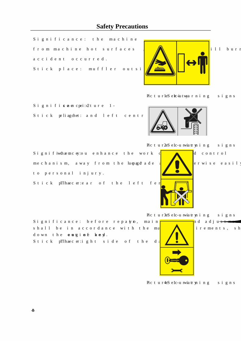
Significance: the machine work to keep a distance
from machine hot surfaces , otherwise it will burn
accident occurred.
Stick place: muffler outside
Picture 1-1 Security warning signs
Significance: see picture 1-2
Stick place: right and left central fenders
Picture 1-2 Security warning signs
Significance: when you enhance the work of the rod control
mechanism, away from the upgrade area, otherwise easily lead
to personal injury.
Stick place: The rear of the left fender.
Picture 1-3 Security warning signs Significance: before repair, maintenance and adjustment,you
shall be in accordance with the manual requirements, shutting
down the engine and out of key.
Stick place: The right side of the dashboard
Picture 1-4 Security warning signs
Safety Precautions
-9-
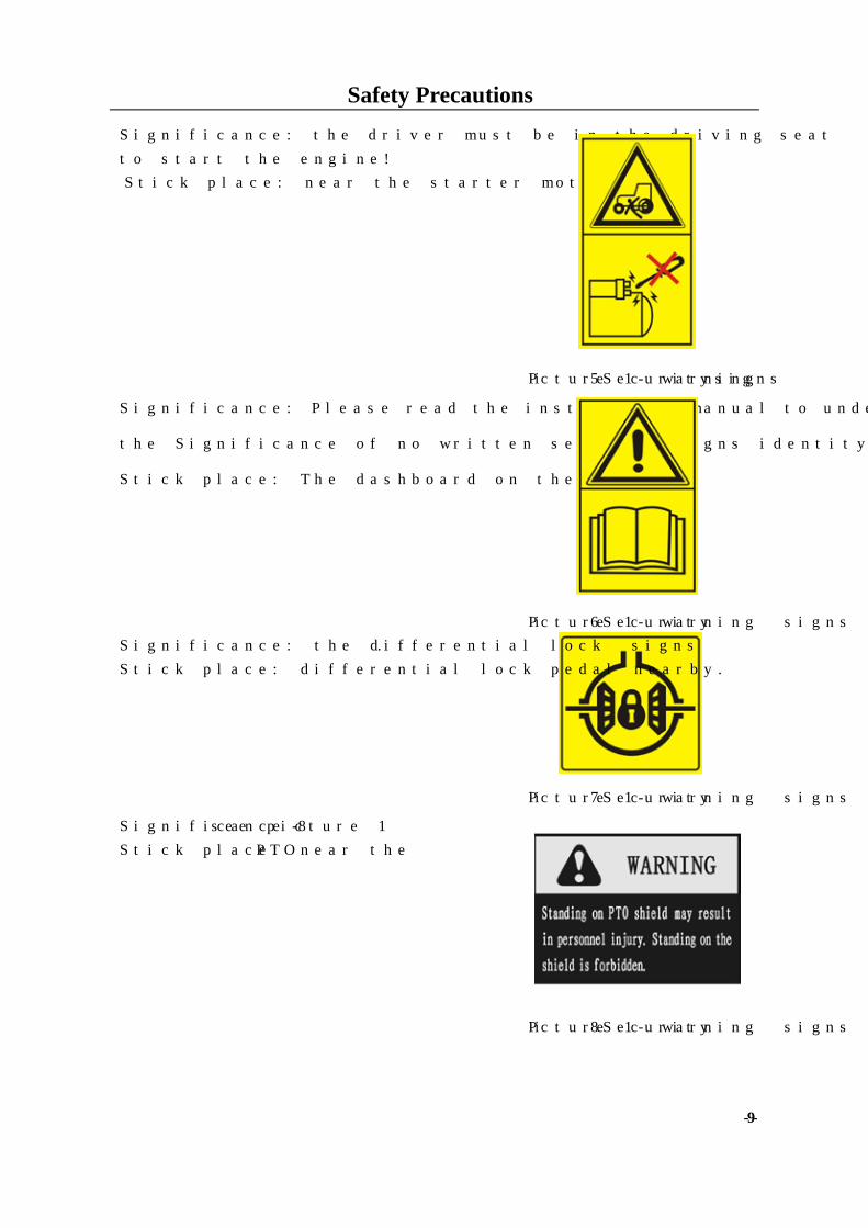
Significance: the driver must be in the driving seat
to start the engine!
Stick place: near the starter motor.
Picture 1-5 Security warning signs
Significance: Please read the instruction manual to understand
the Significance of no written security signs identity.
Stick place: The dashboard on the left.
Picture 1-6 Security warning signs Significance: the differential lock signs.
Stick place: differential lock pedal nearby.
Picture 1-7 Security warning signs
Significance :see picture 1-8
Stick place: near the PTO
Picture 1-8 Security warning signs
Safety Precautions
-10-
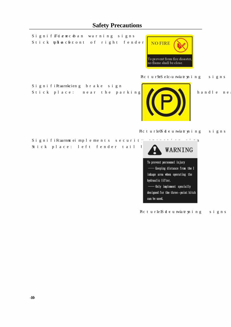
Significance:Fire ban warning signs
Stick place: the front of right fender
Picture 1-9 Security warning signs
Significance: Parking brake sign
Stick place: near the parking brake control handle nearby.
Picture 1-10 Security warning signs
Significance :Farm implements security operation sign
Stick place: left fender tail board.
Picture 1-11 Security warning signs
Operation Instruction
-11-
2. Operation Instruction
The proper operation of the tractor can make the performance of the tractor fully exerted,
reduce the tractor abrasion and accident, and guarantee that the operation on farmland and road
is completed in high-quality, high-efficiency, and low-consumption and safely by the operator.
2.1 Product description
The use, technical maintenance, adjustment, faults and troubleshooting method of the series
tractors are described in the manual.
The series wheeled tractor, which is a kind of multi-purpose medium-sized agricultural
wheeled tractor, is featured by compact structure, convenient for manipulation, flexible steering,
large traction force, convenient for repair and maintenance.
2.2 Operating mechanism and instrument of tractor 2.2.1 Operating mechanism of tractor
The operating mechanism is arranged at the middle position of the tractor and the front, back,
left and right side of the driver.
1. Power take off operating handle (left rear side of driver)
2. Front drive operating handle (left front side of driver)
3. Clutch pedal (front face and left side of driver)
4. Flameout wire handle (front face and left side of driver)
5. Left and right brake pedal (front face and right side of driver)
6. Foot throttle operating handle (right front side of driver)
7. Riser operating handle(right side of the driver, near the seat)
8. Hydraulic out put operating handle (right side of riser operating handle)
9. Main gear shift lever (right side of driver)
10. Sub gear shift lever (right side of driver)
11. Hand throttle operating handle (right side of driver)
2.2.2 Instrument and switches The instrument cluster includes tachometer (including hour meter), fuel gauge, water
temperature gauge, pressure indicator, left and right direction indicator lamp, high beam lamp,
charge lamp, too low oil pressure indicator lamp, preheat indicator lamp, position indicator lamp,
parking braking indicator lamp, etc.
Operation Instruction
-12-
2.3 Start of engine
Notes: Before use, the tractor shall be subject to careful and full inspection, so as to eliminate
hidden trouble and effectively prevent the occurrence of risk and accident.
2.3.1 Preparation before start of engine Ø Careful inspection shall be performed before start. The connection of various parts shall be
firm and reliable; the operating mechanisms shall be able to work normally; the pipe joints of
various parts shall be screwed down without such phenomenon as oil leakage, water leakage
or air leakage;
Ø Inspect the lubricating oil level in the engine oil sump, tractor gear box-rear axle and the
hydraulic system. Sufficient cooling water shall be filled into the radiator of water tank; and
there shall be enough fuel in the fuel tank;
Ø Make the oil circuit switch handle of the fuel tank turned to the relevant consequent position,
making the fuel oil circuit at the connected position;
Ø Inspect the gear box operating lever and power take off operating handle; make the main gear
shift lever, power take off operating handle and front drive operating handle placed at the at
the neutral position, and make the lifter handle placed at drop position.
Ø The hand throttle shall be at half-open status (half throttle position);
Ø Pull the flameout stay wire locking device, let the flameout stay wire relax, at this time, the oil
injection pump in a position of oil supply.
Ø For the new tractor, the tractor given heavy repair or the tractor that has not been used for a
long time, before start, the air in the oil circuit shall be removed firstly, so as to guarantee the
smooth start of the diesel engine. The method is as follows: first, unscrew the air bleed screw
of diesel filter; press the pump with hand; oil pumping will make the air in the oil circuit from
the oil tank to diesel filter exhausted until the discharged fuel has no bubble. Then, screw
down the air bleed screw of the diesel filter, and bleed air with the same method until the
discharged fuel has no bubble.
Ø Put the key into starting switch.
Important notes: 1. The sundries in the water tank meshes shall be cleaned away periodically, so as to
prevent the failure of engine caused by poor heat dissipation;
2. When the tractor carries out field work under poor heat dissipation conditions, to
guarantee the long-time continuous work of the engine, it is suggested to make auxiliary
Operation Instruction
-13-
heat dissipation device installed at the proper position of the tractor.
2.3.2 Start of engine
Notes:
Before the engine is started, shall be ensured that the main and sub gear shift levers
and the front drive operating lever are at the neutral position; and the lifter operating lever
is at drop position, so as to prevent accident and risk caused by sudden start of the tractor.
Important notes:
1. After the engine is started, loosen your grip immediately to let the key automatically
rebound to “ON” position, otherwise the started engine will drive the start of motor, which
will cause motor damage;
2. The continual start time of each time shall not exceed 5s, and the start interval shall
be 15s at least. To maintain the charge performance of the storage battery, the continual
start times shall not exceed 3. If the start fails after three times’ continual start, find out the
reasons and then start again.
1) Start of storage battery: Ø Start under normal temperature (above -5℃): Make the key rotated to “ON” position at
clockwise direction to connect the circuit; then, make the key rotated to “ST” position to
start the engine; after the engine is started, loosen your grip immediately to let the key
automatically rebound to “ON” position. If there is safe start switch, then the main clutch
pedal shall be treaded firstly, and then rotate the key to start the engine.
Ø Start under low temperature (below -5℃): In cold winter, before the engine is started, the
hot water of above 90℃ shall be added into the water tank; close the water drain valve
until hot water flows from the water drain valve of the cylinder, and then make the whole
cooling system filled with hot water. Make the machine oil in the oil sump discharged (it is
better to make the oil discharged when flameout of last time); make the oil dumped into a
container with a cover and heated to (70-90) ℃, and then make the oil filled into the oil
sump. It is forbidden to bake the oil sump with fire.
2) Using assistant battery start: When the battery is not enough, should use assistant battery to start the tractor, (the assistant
battery volume should the same as the battery in the tractor). When start, should parallel the
two batteries, (positive pole connect positive pole, cathode connect cathode). When the
battery needs use outside charger, use the same way to charge the battery. If not take down
the battery, should take down the earth wire.
Operation Instruction
-14-
Notes:
The electrical equipment system is cathode earth wire; the battery connection should ensure
the polarity correct. If wrong, it will break the electric equipment. Usually, fist connect the
positive pole, and then connect the cathode pole. When take off the engine, start motor and
other electric equipment, should take off the cathode earth wire first.
3) Start by making use of pull tractor: When the start is performed by making use of pull tractor, high III stage or high IV stage shall
be applied to the pulled tractor. To guarantee the safety, the speed of the pull tractor shall not
be higher than 15km/h.
Important notes: When the start is performed by making use of pull tractor, once the
engine runs, the main clutch pedal shall be treaded immediately and the throttle should
reduced, so as to prevent the engine flameout.
2.3.3 Operation of engine Ø After the engine is started, the throttle shall be reduced immediately to make the engine at idle
running status. Inspect the engine oil pressure at this time; it shall be ensured that the
machine oil pressure is no less than 98 kPa. At this time, the oil pressure indicator lamp goes
out.
Ø After the engine is started, full-load running shall not be performed immediately; and the
engine shall be subject to intermediate speed no-load running for heating. When the
temperature of the cooling liquid is above 60℃, the revolution speed can be increased to the
maximum speed for full-load running.
Ø The revolution speed and load of engine shall be slowly increased or reduced. In particular,
for the engine that is just started, sudden high speed running is unallowable.
Ø When engine running, the pressure of machine oil and temperature of cooling liquid shall be
inspected frequently.
2.4 Start of tractor
Ø When the engine is under low speed status, tread the clutch pedal, and then make the gear
shift lever of gear box placed at the needed stage;
Ø Push the locating detent rocker arm downwards, and loosen the parking brake;
Ø Whistling sound shall be made and observe whether there is barrier around;
Ø Gradually increase the revolution speed of engine and slowly loosen the clutch pedal to make
the tractor start smoothly. After the tractor starts moving, quickly loosen the clutch pedal, so as
Operation Instruction
-15-
to avoid the slipping of clutch.
Ø Gradually increase the throttle to make the tractor reach the needed working speed;
Ø During the use process, the driving speed of tractor shall not be reduced by adopting the
method of semi-combination of clutch. During the driving process, the feet shall not be always
placed on the clutch pedal, so as to avoid the accelerated abrasion of disengaging lever and
friction plate. Clutch pedal; avoid the slipping of clutch.
Important notes: 1. To prevent collision of teeth of drive gear of gear box and the early damage of clutch,
high stage start is forbidden;
2. The parking brake must be loosened before the tractor starts moving, so as to
prevent the damage of other working parts;
3. When putting into gear or gear shift, the clutch pedal must be treaded to separate the
main clutch, so as to prevent collision of teeth of drive gear of gear box and the early
damage of clutch.
2.5 Steering of tractor
When steering of tractor on road, the horn switch on the instrument panel shall be operated
firstly; whistling sound shall be made for warning, and then make a turn. If the speed is high,
reduce the speed firstly. In case of shallow turn, steer early and slowly; in case of sharp turn, steer
late and quickly.
When the tractor have little steering or steering on the soft field, because of the front wheel
side slip cause the steering unavailable , can steering the steering wheel and tread the pedal at
the same time to help steering.
Warning:
1. When the tractor is driving at a high speed, making a sharp turn by adopting
unilateral braking is unallowable. When the front wheel make a wide turn, if there is squeak
when the safety valve works, the steering wheel shall be withdrawn a little, so as to avoid
the damage caused by long-time overload of hydraulic steering system and steering failure
accident;
2. When making a turn or head back during field work, the working parts of agricultural
implement inserted into soil must be lifted above ground, so as to avoid damage of
agricultural implement or personal injury.
Operation Instruction
-16-
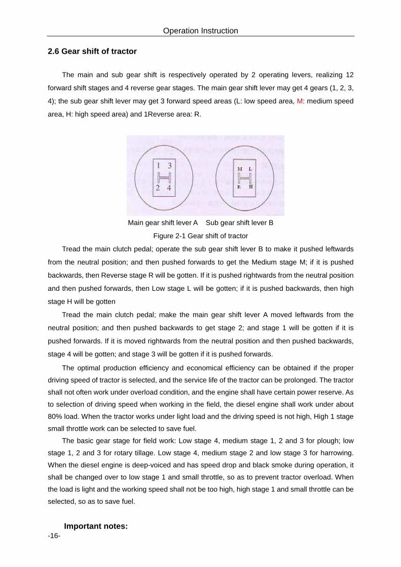
2.6 Gear shift of tractor
The main and sub gear shift is respectively operated by 2 operating levers, realizing 12
forward shift stages and 4 reverse gear stages. The main gear shift lever may get 4 gears (1, 2, 3,
4); the sub gear shift lever may get 3 forward speed areas (L: low speed area, M: medium speed
area, H: high speed area) and 1Reverse area: R.
Main gear shift lever A Sub gear shift lever B
Figure 2-1 Gear shift of tractor
Tread the main clutch pedal; operate the sub gear shift lever B to make it pushed leftwards
from the neutral position; and then pushed forwards to get the Medium stage M; if it is pushed
backwards, then Reverse stage R will be gotten. If it is pushed rightwards from the neutral position
and then pushed forwards, then Low stage L will be gotten; if it is pushed backwards, then high
stage H will be gotten
Tread the main clutch pedal; make the main gear shift lever A moved leftwards from the
neutral position; and then pushed backwards to get stage 2; and stage 1 will be gotten if it is
pushed forwards. If it is moved rightwards from the neutral position and then pushed backwards,
stage 4 will be gotten; and stage 3 will be gotten if it is pushed forwards.
The optimal production efficiency and economical efficiency can be obtained if the proper
driving speed of tractor is selected, and the service life of the tractor can be prolonged. The tractor
shall not often work under overload condition, and the engine shall have certain power reserve. As
to selection of driving speed when working in the field, the diesel engine shall work under about
80% load. When the tractor works under light load and the driving speed is not high, High 1 stage
small throttle work can be selected to save fuel.
The basic gear stage for field work: Low stage 4, medium stage 1, 2 and 3 for plough; low
stage 1, 2 and 3 for rotary tillage. Low stage 4, medium stage 2 and low stage 3 for harrowing.
When the diesel engine is deep-voiced and has speed drop and black smoke during operation, it
shall be changed over to low stage 1 and small throttle, so as to prevent tractor overload. When
the load is light and the working speed shall not be too high, high stage 1 and small throttle can be
selected, so as to save fuel.
Important notes:
Operation Instruction
-17-
1. When engine running, before gear shift, the main clutch pedal shall be treaded to
floor, and the gear shift shall be performed after several seconds, so as to prevent poor
engagement of sliding sleeve of gear box (which will lead to “collision of teeth”);
2. The tractor only can be at back gear stage when it is still;
3. Do not make the hands placed on the gear shift lever when the tractor is driving, or
the hand pressure will be transmitted to the gear shift fork in the gear box, which will lead
to premature wear of the shift fork.
2.7 Operation of Differential Lock During the operation or working process of tractor, if the tractor can not move forward due to
sticking or the unilateral driving wheel is slipping, the differential lock can be connected according
to the following steps to rigidly connect the left driving wheel and the right driving wheel so as to
drive the tractor out of the slipping section at the same speed.
Ø Step on the main clutch pedal and operate the gear shift lever to change to low gear;
Ø Turn the throttle operating handle to the maximum oil-supply position;
Ø Step on the differential lock operating pedal by the right foot;
Ø Loosen the clutch pedal smoothly, so as to make the tractor start smoothly;
Ø Loosen the differential lock pedal after driving out of the slipping section, and the
differential lock will be disengaged automatically.
Important matters: it is forbidden to use the differential lock when the tractor is
driving normally and turning in case of damaging the machine component and wearing the
acceleration tire.
2.8 Using of Front Drive Axle This series of four-wheel drive tractor works in farm fields under heavy load or works on humid
and soft soil; if only driven by the rear wheel, the traction property of the tractor may present
insufficiently; at this time, hanging the front drive axle can increase the traction force of the tractor
and reduce the slipping rate, thereby improving the working adaptability of the tractor. In order to
be convenient for connecting and separating the front drive axle, the following operation
procedures shall be followed:
2.8.1 Hanging of the Front Drive Axle
Step on the main clutch pedal, hang the position of the gear-box well, and then loose the
clutch pedal slowly, wait for the slighting moving of the tractor and timely pull the front drive axle
operation handle upward, so as to change two-wheel drive to four-wheel drive.
Operation Instruction
-18-
2.8.2 Disconnection of the Front Drive Axle
When it is necessary to disconnect the front drive axle, step on the main clutch pedal and
push the front axle operation handle downward, so as to separate the front drive axle
Important matters: 1. When the tractor is conveying on a hard roadway for ordinary transportation, it is
forbidden to connect the front drive axle, otherwise it will cause early stage abrasion of the
front wheel and increase oil consumption. Only when the roadway is slipping and the back
wheel can easily slip after climbing large slope during raining or snowing day, the front
drive axle be connected. After the tractor drives out of the difficult section, the front drive
axle shall be separated.
2. When the tractor is conveying, the front tire wears faster and the tire treads at the left
and right side of the tire wear unevenly; the left tire and right tire can be exchanged for use
according to the condition. 2.9 Braking of the Tractor
Generally, firstly decrease the throttle, step on the clutch pedal, and then gradually step on
the brake pedal according to the condition to steadily pause the tractor.
For emergency stop, you shall simultaneously step on the clutch and the brake pedal and
cannot solely step on the brake pedal, so as to prevent rapid abrasion of the brake friction plate or
causing engine stop.
When a trailer is added for braking, you shall adjust the length of the brake valve hang rod to
firstly brake the trailer and then brake the main engine.
When the tractor is running on road, you shall lock the left brake pedal and the right brake
pedal together by the chain board.
Warning:
1. Before departure of each time, you shall uniformly check the oil level of the brake oil
tank as well as whether there is oil leakage generated at the brake piping or not; if the oil
level of the oil tank is too low or there is oil leakage generated at the brake piping, you shall
timely find out the reason, repair it, otherwise major incident like brake failure will be
raised.
2. When the tractor is running on road, you must interlock the left brake pedal and the
right brake pedal together, so as to prevent off tracking and even overturning of the tractor
when braking.
Operation Instruction
-19-
2.10 Stopping of Tractor Stop and Flameout of Engine
Flameout of the tractor and stopping of the tractor shall follow the following procedures:
Ø Decrease the throttle, and reduce the running speed of the tractor.
Ø Step on the clutch pedal, then step on the brake pedal and place the gear shift lever at
the position of neutral gear after the tractor stops
Ø Loosen the clutch and brake pedal, and then decrease the throttle to lead the engine run
under idle speed.
Ø Pull the flameout pull rod back, the oil pump stops supplying oil and the engine shuts
down immediately, and then push it to the position of oil supply
Ø Turn the power switch to the off position, and shut down all the power sources.
Notices:
1. After stopping and before flameout of the engine, the driver is forbidden to leave the tractor,
so as to prevent the tractor from starting suddenly, which will cause accidental risk.
2. If the tractor must stop at a slope land, you shall engage the gear (engage the forward gear
at upslope position, and engage the backward gear at downslope position), and must use parking
brake and plug the back wheels by triangle brake shoes, so as to prevent the tractor from
suddenly starting and out of control automatically, which will cause accidental risk.
Important matters:
1.When the temperature is lower than zero DEG in winter, turn on the drain valve of the
water tank and the drain switch of the engine of the tractor, which does not use antifreeze
when the engine is running under idle speed, to discharge cooling water out, and then shut
down the engine, so as to prevent freezing of the cooling water which will crack the engine
body through frosting;
2. After discharging water in winter, in order to prevent residual water in the outlet pipe
of the water tank from cracking the water pipe through frosting, suggest the user to turn on
the water discharge switch of the engine after the engine stops, position the flameout
handle at the position of flameout and drag the engine to run 2 to 3 times for 15 second
with a interval of 2 to 3 minutes, so as to prevent discharging all of the water in the water
pipe.
Operation Instruction
-20-
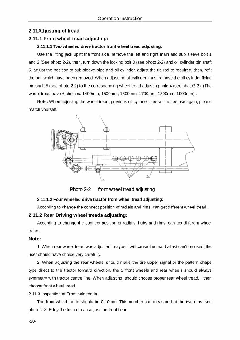
2.11Adjusting of tread 2.11.1 Front wheel tread adjusting:
2.11.1.1 Two wheeled drive tractor front wheel tread adjusting:
Use the lifting jack uplift the front axle, remove the left and right main and sub sleeve bolt 1
and 2 (See photo 2-2), then, turn down the locking bolt 3 (see photo 2-2) and oil cylinder pin shaft
5, adjust the position of sub-sleeve pipe and oil cylinder, adjust the tie rod to required, then, refit
the bolt which have been removed. When adjust the oil cylinder, must remove the oil cylinder fixing
pin shaft 5 (see photo 2-2) to the corresponding wheel tread adjusting hole 4 (see photo2-2). (The
wheel tread have 6 choices: 1400mm, 1500mm, 1600mm, 1700mm, 1800mm, 1900mm) .
Note: When adjusting the wheel tread, previous oil cylinder pipe will not be use again, please
match yourself.
Photo 2-2 front wheel tread adjusting
2.11.1.2 Four wheeled drive tractor front wheel tread adjusting:
According to change the connect position of radials and rims, can get different wheel tread.
2.11.2 Rear Driving wheel treads adjusting: According to change the connect position of radials, hubs and rims, can get different wheel
tread.
Note: 1. When rear wheel tread was adjusted, maybe it will cause the rear ballast can’t be used, the
user should have choice very carefully.
2. When adjusting the rear wheels, should make the tire upper signal or the pattern shape
type direct to the tractor forward direction, the 2 front wheels and rear wheels should always
symmetry with tractor centre line. When adjusting, should choose proper rear wheel tread, then
choose front wheel tread.
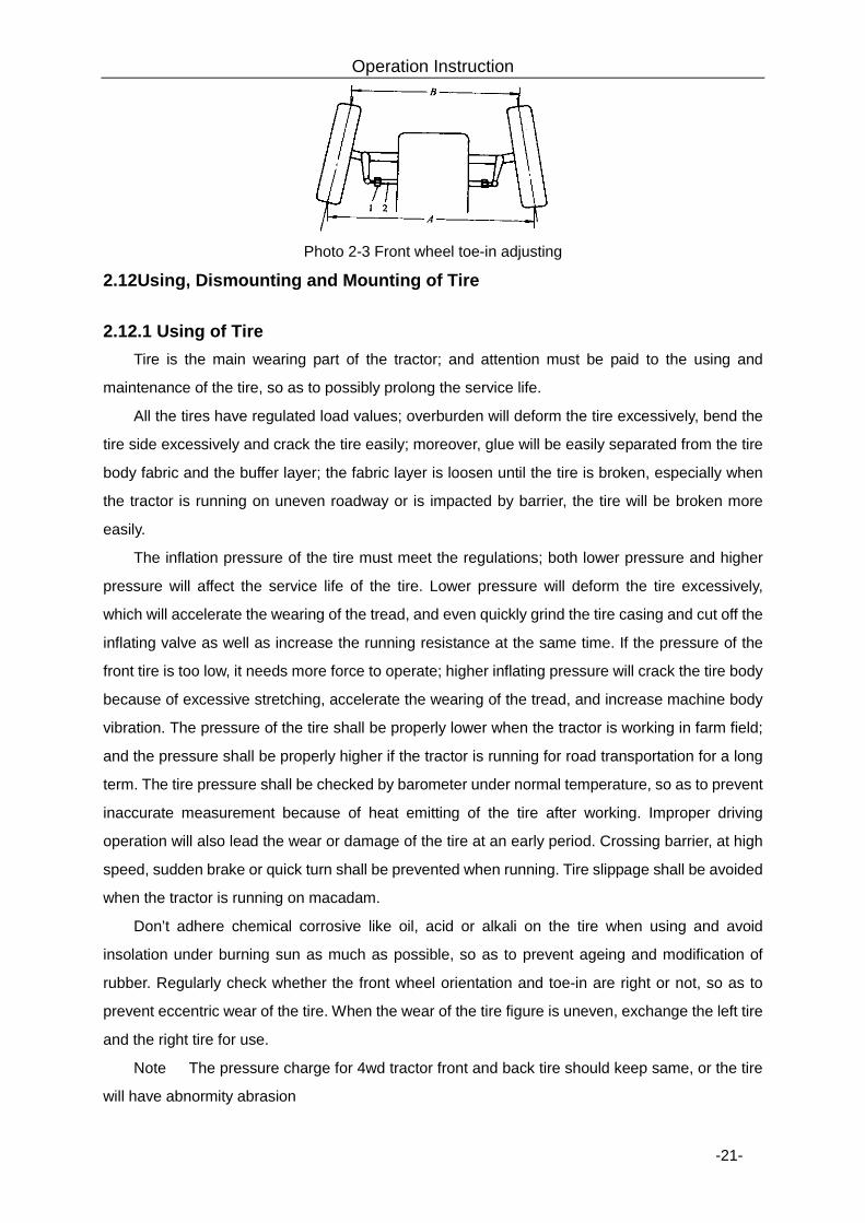
2.11.3 Inspection of Front axle toe-in.
The front wheel toe-in should be 0-10mm. This number can measured at the two rims, see
photo 2-3. Eddy the tie rod, can adjust the front tie-in.
Operation Instruction
-21-
Photo 2-3 Front wheel toe-in adjusting
2.12Using, Dismounting and Mounting of Tire
2.12.1 Using of Tire Tire is the main wearing part of the tractor; and attention must be paid to the using and
maintenance of the tire, so as to possibly prolong the service life.
All the tires have regulated load values; overburden will deform the tire excessively, bend the
tire side excessively and crack the tire easily; moreover, glue will be easily separated from the tire
body fabric and the buffer layer; the fabric layer is loosen until the tire is broken, especially when
the tractor is running on uneven roadway or is impacted by barrier, the tire will be broken more
easily.
The inflation pressure of the tire must meet the regulations; both lower pressure and higher
pressure will affect the service life of the tire. Lower pressure will deform the tire excessively,
which will accelerate the wearing of the tread, and even quickly grind the tire casing and cut off the
inflating valve as well as increase the running resistance at the same time. If the pressure of the
front tire is too low, it needs more force to operate; higher inflating pressure will crack the tire body
because of excessive stretching, accelerate the wearing of the tread, and increase machine body
vibration. The pressure of the tire shall be properly lower when the tractor is working in farm field;
and the pressure shall be properly higher if the tractor is running for road transportation for a long
term. The tire pressure shall be checked by barometer under normal temperature, so as to prevent
inaccurate measurement because of heat emitting of the tire after working. Improper driving
operation will also lead the wear or damage of the tire at an early period. Crossing barrier, at high
speed, sudden brake or quick turn shall be prevented when running. Tire slippage shall be avoided
when the tractor is running on macadam.
Don’t adhere chemical corrosive like oil, acid or alkali on the tire when using and avoid
insolation under burning sun as much as possible, so as to prevent ageing and modification of
rubber. Regularly check whether the front wheel orientation and toe-in are right or not, so as to
prevent eccentric wear of the tire. When the wear of the tire figure is uneven, exchange the left tire
and the right tire for use.
Note: The pressure charge for 4wd tractor front and back tire should keep same, or the tire
will have abnormity abrasion
Operation Instruction
-22-
2.12.2 Dismounting and Mounting of the Tire Dismounting of the tire
Special tools shall be used for dismounting the tire and it is forbidden to use hard tools (like
screwdriver) and sledge hammer to beat the tire, so as to prevent puncturing the tire or damaging
the tire edge and rim section.
When dismounting the tire, you shall discharge the air at first, and press the tire edge at two
sides of the tire casing into the groove of the rim section; then use a crowbar to pry the tire edge at
one side out of the rim section from the position near the inflating valve; and then use two
crowbars alternately pry the whole tire edge out. After taking the inner tire out, use the same
method to pry out the tire edge at the other side, and take down the tire casing.
Mounting of the tire
When mounting the tire, firstly check whether the rim section and the tire are matched or not,
and there shall be no burrs and serious deformation at the edge of the rim section; then eliminate
rust on the rim section, check whether there is breakage on the tire or not. After wiping up each
spare part, coat a thin layer of talcum powder between the inner tire and the tire casing during
mounting. Lay the rim section flat, mount the tire casing and step by foot or pry it into the rim
section by crowbar.
Put the inner tire in (slightly underlay the tire casing) and use galvanized wire to fix the
inflating valve in the inflating valve hole of the rim section to prevent slipping. Use a crowbar to pry
one side of the tire casing into the rim section (it will spend most force at the last section and use a
hand hammer to slightly knock the crowbar). Finally, check whether the position of the inflating
valve is inclined or not and whether the rim edge and the rim section are closely fitted or not. When
inflating, recheck whether the inner tire is broken or not by prying, inflate and at the same time
knock the tire casing by the hand hammer, after inflating to the regulated pressure, then discharge
half of the air, so as to make the inner tire expand normally and eliminate cockle phenomenon.
When mounting the tire onto the tractor, you shall also pay attention to the direction of the tire
figure; otherwise, the adhering property and abrasion performance will be influenced, and mud will
be deposited.
Warning: it is forbidden to dismount the connecting bolts of the tire, the drive
hub and the hub; otherwise they will fly out and hurt people.
2.13 Using of Balance Weight
2.13.1 Rear balance weight When the tractor is working in farm field, the quantity of the balance weight can be selected
Operation Instruction
-23-
according to different working patterns in order to improve the working performance of the tractor.
Each piece of cast iron balance weight weighs 50kg, and at most 3 pieces can be mounted at one
side (150kg).
Notice: Before dismounting the rear wheel which is provided with the rear
balance weight from the tractor, you shall firstly dismount the back balance weight from the
tire, so as to prevent the risk of losing balance.
2.13.2 Front balance weight
In order to adjust the relation between the front balance weight and the back balance weight
of the tractor, it is necessary to mount the front balance weight block at the front part of the tractor.
For plough work under heavy load or hanging machines like large scale seeding machinery, in
order to guarantee the head o f the tractor does not raise and run safely, the front balance weight
with sufficient weight must be mounted.
The front ballast weight 130Kg.
At most 10 pieces of cast iron front balance weights can be selected and mounted on the
tractor [each piece weighs 40kg].
Notice:
Attach the big implements at the rear of tractor, in order to keep your safety, must fit with enough front ballast, or will have turn over dangerous.
2.14 Adjustment of the Driver’s Seat 2.14.1 Adjusting Seat front and rear.
Loosen bolt under the seat. The driver can adjust the seat according to his/her height. After
adjustment, tighten the bolt。
2.14.2 Stiffness of the driver's seat adjustment
According to the operator's height, weight adjustment to adjust the driver's seat hand wheel
Notice:
1. To safety, seat adjustment must be implemented when the tractor is under static
condition, so as to prevent accidental risk.
2. Seat stiffness can not be stressed too soft,when you driving on rugged roads, you
should pay more attention to this point,in order to avoid risk of accident.
Operation Instruction
-24-
2.15 Covering Panels of the Tractor
The covering panels mainly comprise an engine cover, a driving cab, a splash guard, an instrument desk, a floor, accessories, etc.
2.15.1 Engine cover The engine cover of the tractor adopts a streamline move-in structure which has an elegant
appearance.
2.15.2 Instrument desk The electrical appliance switches and instrument clusters of the tractor are uniformly mounted
on the instrument desk; and the instrument desk mainly takes the effects of bracket of the control
switch as well as decoration and seal.
2.15.3 Cab (Options) The cab of the tractor is manufactured by a framework which is welded by tubular-shaped
profiled materials and inlayed by large area of spatial curved glass.
2.15.4 Fan of the cab (Options) The cab is provided with interior trim and fan.
2.15.5 Interior trim of the cab (Options) The interior trim comprises a splash guard interior trim, a floor mat, an instrument desk, an
interior cresting, etc.
2.16 Using of the working device of the tractor
This series of tractors mainly have the working devices as follows: (Partially selected and
installed)
Ø Hydraulic raiser: shall preferentially adopt force position comprehensive adjustment
when working with plough so as to guarantee the working effect.
Ø Hydraulic output device: can be used for hydraulic reversible plow, hydraulic harrow,
etc.;
Ø Suspension mechanism :is mainly used for the hanging and connecting of hanging
agricultural machineries.
Ø Power output device: is mainly used for agricultural machineries which needs power
drive.
Ø Pendulum traction apparatus:is mainly used for demand heavy duty harrow, mower,
traction seeder, single axle trailer, etc.
Ø Traction frame:is mainly used for double axle trailer, etc.
2.16.1 Operation of hydraulic raiser
Operation Instruction
-25-
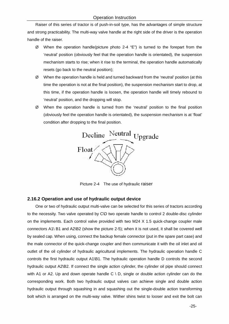
Raiser of this series of tractor is of push-in-soil type, has the advantages of simple structure
and strong practicability. The multi-way valve handle at the right side of the driver is the operation
handle of the raiser.
Ø When the operation handle(picture photo 2-4 “E”) is turned to the forepart from the
‘neutral’ position (obviously feel that the operation handle is orientated), the suspension
mechanism starts to rise; when it rise to the terminal, the operation handle automatically
resets (go back to the neutral position);
Ø When the operation handle is held and turned backward from the ‘neutral’ position (at this
time the operation is not at the final position), the suspension mechanism start to drop, at
this time, if the operation handle is loosen, the operation handle will timely rebound to
‘neutral’ position, and the dropping will stop.
Ø When the operation handle is turned from the ‘neutral’ position to the final position
(obviously feel the operation handle is orientated), the suspension mechanism is at ‘float’
condition after dropping to the final position.
Picture 2-4 The use of hydraulic raiser
2.16.2 Operation and use of hydraulic output device One or two of hydraulic output multi-valve can be selected for this series of tractors according
to the necessity. Two valve operated by C\D two operate handle to control 2 double-disc cylinder
on the implements. Each control valve provided with two M24 X 1.5 quick-change coupler male
connectors A1\ B1 and A2\B2 (show the picture 2-5); when it is not used, it shall be covered well
by sealed cap. When using, connect the backup female connector (put in the spare part case) and
the male connector of the quick-change coupler and then communicate it with the oil inlet and oil
outlet of the oil cylinder of hydraulic agricultural implements. The hydraulic operation handle C
controls the first hydraulic output A1\B1. The hydraulic operation handle D controls the second
hydraulic output A2\B2. If connect the single action cylinder, the cylinder oil pipe should connect
with A1 or A2. Up and down operate handle C \ D, single or double action cylinder can do the
corresponding work. Both two hydraulic output valves can achieve single and double action
hydraulic output through squashing in and squashing out the single-double action transforming
bolt which is arranged on the multi-way valve. Wither shins twist to looser and exit the bolt can
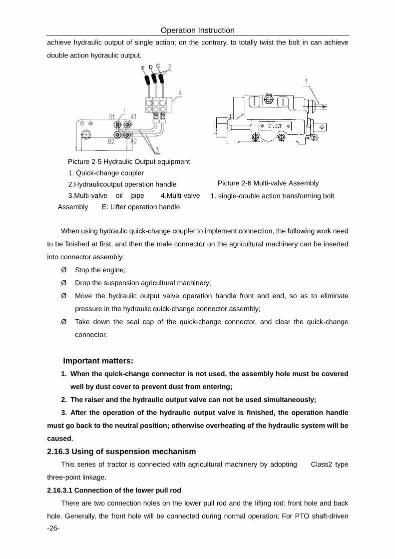
Operation Instruction
-26-
achieve hydraulic output of single action; on the contrary, to totally twist the bolt in can achieve
double action hydraulic output.
Picture 2-5 Hydraulic Output equipment 1. Quick-change coupler 2.Hydraulicoutput operation handle 3.Multi-valve oil pipe 4.Multi-valve
Assembly E: Lifter operation handle
Picture 2-6 Multi-valve Assembly
1. single-double action transforming bolt
When using hydraulic quick-change coupler to implement connection, the following work need
to be finished at first, and then the male connector on the agricultural machinery can be inserted
into connector assembly:
Ø Stop the engine;
Ø Drop the suspension agricultural machinery;
Ø Move the hydraulic output valve operation handle front and end, so as to eliminate
pressure in the hydraulic quick-change connector assembly;
Ø Take down the seal cap of the quick-change connector, and clear the quick-change
connector.
Important matters: 1. When the quick-change connector is not used, the assembly hole must be covered
well by dust cover to prevent dust from entering;
2. The raiser and the hydraulic output valve can not be used simultaneously;
3. After the operation of the hydraulic output valve is finished, the operation handle
must go back to the neutral position; otherwise overheating of the hydraulic system will be
caused.
2.16.3 Using of suspension mechanism This series of tractor is connected with agricultural machinery by adopting 、 Class2 type
three-point linkage.
2.16.3.1 Connection of the lower pull rod
There are two connection holes on the lower pull rod and the lifting rod: front hole and back
hole. Generally, the front hole will be connected during normal operation; For PTO shaft-driven
Operation Instruction
-27-
machines and the large duplex operating farm implements (such as rotary tiller, etc.) are normally
connected back holes.
2.16.3.2 Connecting of the lifting rod
Generally, the length of the lifting rod shall be adjusted at the central position. The adjustment
of the left lifting rod and the right lifting rod shall be uniformly implemented through rotating the
welding of the central lifting rod conduit. To adjust the lifting rod is mainly to adjust the lateral level
position of the agricultural machinery.
2.16.3.3 Connection of the upper pull rod
To adjust the height of the upper pull rod is mainly used to adjust the longitude horizontal
position of the agricultural machinery. And bearings to connect the two holes for the selection. It
can choose the most suitable location to connect the farm implements column height.
2.16.3.4 Adjustment of the limit rod
The limit rod is mainly used to limit the lateral oscillating quantity of the agricultural machinery
(namely the lower pull rod). To insert the lock pin into the round hole at the front of the limit sleeve
can fix the limit rod without moving. To rotate limit sleeve with threads can adjust the length of the
limit rod. The round hole at the back side is a jack socket for placing the lock pin when adjusting
the length of the limit rod.
The amount of movement of the limit rod can be selected according to the working type of the
agricultural machinery. A certain amount of movement shall be maintained for the limit rod when
the tractor is equipped with plow, harrow, etc, which can maintain the tractor with good operation
performance. The limit rod shall be fixed without moving when the tractor is equipped with rotary
cultivator, mower, etc.
Requirements of suspension mechanism:
⑴、When you operations, allowing farm implements relatively tractor smaller swing。It is
suitable for a smaller load, the small farm implements requirements of lateral swing. Such as
cultivators, seed drills rotary tiller.
⑵, When the tractors with a support wheel mounted implements work, multiple valve must
use a "floating" position work.
⑶, When the tractor turning at the edge of a farm , you must be upgraded the hanging tools
off the ground,then begin turning; After turn around, into the straight-line driving, and then fall
down the agricultural implements.
⑷ , When the tractors with mounted implements long-distance transport, adjust the
suspension rods short, and rose to the highest position, limit rods can not be free to expand. And
also need to tighten the lock nut on the rod and limit rod.
⑸,When the tractors with mounted implements transportation or headland turn, it doesn't
allow high-speed steering and high-speed obstacle.
⑹,When there is no safety measures, it is prohibited to adjust, clean or do other work below
Operation Instruction
-28-
the upgrade farm tools.
2.16.4 Operation of the power output device The power output shaft of this series of tractor is of a postposition detached type. When the
assorted machinery equipment of the tractor needs power output, the operation shall follow the
procedures as follows:
Ø Put the farm implements and hitch connection;
Ø Pull the vice clutch control handle, pace the power output operation handle at the
middle neutral position;
Ø Dismount the traction frame and the cover of the power output shaft, and then connect
the universal joint on the agricultural machinery and the power output shaft;
Ø Mount the power output shield well.
Ø Riser manipulation of the handle placed in the "upgrade" position, to enhance agricultural
implements;
Ø Again to pull the vice clutch control handle, according to the power output shaft speed. To
press the power output operation handle downward can obtain high speed which is
1000r/min( or850 r/min、or 760r/min); if lifting upwards, low speed which is 760r/min( or
540r/min) can be obtained; When don't need power output,power output manipulation
of the handle should be in the middle of the neutral position, and power output shaft
sleeve tube re-installed on the screw.
Warning: It is forbidden to get close to the agricultural machinery when the power output is
connected in case of danger.
2.16.5 Operation of towing device 2.16.5.1 Pendulum type draw bar
The pendulum type draw bar is only used for the trailed implements. The rear end of the
drawbar is connected to the farm tools through the towing pin and the drawbar can swing laterally
for the convenience of the connection with the farm tools. During operation, the drawbar can swing
left and right. However, when the tractor wants to draw the farm tools back, it is necessary to insert
two locating pins into the holes of draw plate to prevent the drawbar from swinging. To change the
height of towing point, it is allowed to turn the drawbar to create the towing height applicable to the
farm tools.
2.16.5.2 Hook bracket
The hook is applied to various trailers, not used with the pendulum type draw bar.
Warning:
Operation Instruction
-29-
1. The overload is not allowed at the towing operation and the operation with trailer.
2. When braking, the trailer shall be braked slightly prior to the tractor.
2.16.6 Operation and adjustment of electric system
For this tractor, the electric system has the voltage of 12V and uses the silicon rectification
generator, cathode earthing and double-line system. The system is composed of engine starting
device and lighting signaling device, of which the engine starting device consists of starting motor
and silicon rectification generator. For the operation and maintenance of above devices, see
Engine Operation and Maintenance Manual. The lighting signaling device consists of front
combined lamp, rear lamp, roof lamp of driver cap, handrail lamp (turning, position), rear tail lamp
(turning, position and braking), instrument cluster, horn, fuse box, etc.
2.17 Running-in of tractor
Before the tractor is put into operation, it shall operate for some time under the specified
lubrication, rotation speed and load conditions, and it shall be subject to necessary inspection,
adjustment and maintenance to reach its normal technical condition. This work is known as
running-in.
2.17.1 Preparation before running-in Ø During running-in, the tractor shall be subject to the American and every 50h (hour)
technical maintenance; and every 50h (hour) technical maintenance;
Ø Check and fasten the bolts, nuts and screws outside the tractor;
Ø Fill the grease onto each lubricating point;
Ø Check the engine, gear case, front driving axle, steering gear and lifter for oil level, and fill
it if insufficient;
Ø Fill up the fuel and cooling fluid in accordance with the label;
Ø Check the tire pressure for normal condition;
Ø Check the electrical line for normal and reliable connection;
Ø Check whether the battery needs being charged;
Ø Place the control handles at their neutral position.
2.17.2 Running-in of engine at idle speed The diesel engine shall be subject to 15min running-in at idle speed. Start the engine as the
sequence specified in“ Diesel Engine Operation and Maintenance Manual”, and from low speed
(small throttle), medium speed (medium throttle) to high speed (large throttle), operate the engine
for 5min in turn.
Operation Instruction
-30-
During the running-in of diesel engine at idle speed, carefully check the engine, air
compressor and hydraulic oil pump for normal operation, check whether there is abnormal
phenomenon or noise, check whether there is water leakage and oil leakage, and check the
instrument for normal operation. If any, shut down the tractor for troubleshooting and then conduct
running-in again.
The following running-in can be done only after the engine operates normally.
2.17.3 Running-in of power take-off shaft at no load Place the engine throttle control handle at its position of medium throttle to make the engine
operate at medium speed, respectively the power take-off shaft at low speed and high speed for
5min, and check whether there is abnormal phenomenon. After running-in, be sure to place the
power take-off shaft at its neutral position.
2.17.4 Running-in of hydraulic system Start the engine, place the throttle control handle at its position of medium throttle, control the
distributor handle (lifter operation handle), lift and lower the suspension mechanism for several
times, check whether there is abnormal phenomenon, hang the applicable farm tools about 600kg
onto the suspension mechanism, operate the engine at high speed, control the distributor handle,
lift and lower the suspension mechanism at its full travel for 20 times at least, check whether the
suspension mechanism can stay at its highest position or required position, check the lift/lower
time and check whether there is leakage.
When the tractor is at rest, operate the engine at low speed, medium speed and high speed,
stably control the steering wheel leftwards and rightwards for 10 times, check the front wheels of
tractor for their leftward, rightward and steering operation, check whether the sound is normal, and
check whether the steering wheel is controlled conveniently and stably.
If any fault is found during running-in, it is necessary to find out the reason and eliminate the
fault.
2.17.5 Running-in of tractor without and with load After the idle running-in and the running-in of power take-off shaft and hydraulic system, when
the technical condition of tractor is correct, it is necessary to conduct the running-in of complete
machine as per the following form 2-1 sequence and time. Total running-in is 60h. During the
running-in at no load, conduct the turning operation and properly use the brake at single side at
low speed, and check the emergency brake at high speed.
After the running-in at no load, conduct the running-in under load when the tractor has
completely normal technical condition. During the running-in, the load must be from small to large
and the gear must be from low speed to high speed. For the tractor fitted with the creeper gear, it is
allowed to conduct the running-in under the creeper gear.
Running-in precautions:
Ø Check the electrical equipment and instrument for normal readings;
Operation Instruction
-31-
Ø Check the engine for normal operation;
Ø Check the clutch for easy combination and thorough separation;
Ø Check whether the gear of gear case is shifted conveniently and whether there is
disorder engagement and spontaneous out-of-gear;
Ø Check the brake for reliable operation;
Ø Check the differential lock for reliable combination and separation;
Ø Check the driving axle for reliable combination and separation;
If any fault is found during running-in, it is necessary to find out the reason, eliminate the fault
and continue the running-in.
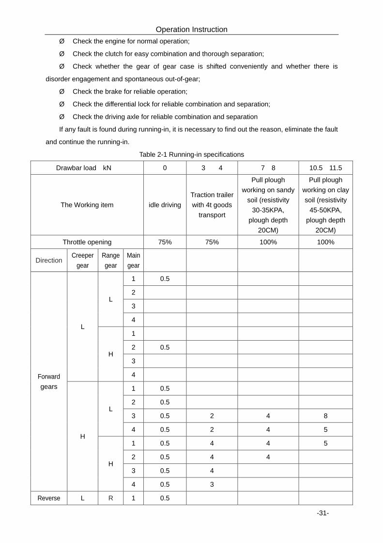
Table 2-1 Running-in specifications
Drawbar load(kN) 0 3 ~ 4 7~8 10.5~11.5
The Working item idle driving Traction trailer with 4t goods
transport
Pull plough working on sandy
soil (resistivity 30-35KPA,
plough depth 20CM)
Pull plough working on clay soil (resistivity
45-50KPA, plough depth
20CM)
Throttle opening 75% 75% 100% 100%
Direction Creeper
gear Range gear
Main gear
Forward gears
L
L
1 0.5
2
3
4
H
1
2 0.5
3
4
H
L
1 0.5
2 0.5
3 0.5 2 4 8
4 0.5 2 4 5
H
1 0.5 4 4 5
2 0.5 4 4
3 0.5 4
4 0.5 3
Reverse L R 1 0.5
Operation Instruction
-32-
gear 2 0.5
3 0.5
4 0.5
H R
1 0.5
2 0.5
3 0.5
4 0.5
Total time(h) 7 19 16 18
2.17.6 Technical maintenance after running-in After the running-in of tractor, there may be some filings or dirt in the drive system, lubrication
system and hydraulic system, so it is necessary to clean and replace all the lubrication oils and the
oil used for the hydraulic system and to conduct the necessary technical maintenance before the
tractor is put into normal operation.
The technical maintenance after ruining-in is as follows:
Ø After shutdown, discharge the engine oil from the engine oil sump and the oil tank of
steering system immediately, clean the oil pan, engine oil filter screen, diesel filter, engine oil filter,
air cleaner and filter screen in steering tank, replace the filter element of diesel filter and engine oil
filter and refill the lubrication oil as required.
Ø Discharge the oil from the transmission system, lifter and front driving axle immediately,
and fill the proper light diesel oil or coal oil, do not start the engine, make the tractor run forwards
or backwards at low speed for about 3min, lift the front and rear tires from the ground, rotate the
front and rear tires along tow directions for about 3min, immediately discharge the cleaning liquid,
and remove the oil suction filter of lifter for cleaning, reassemble it, and refill the oil to drive system,
lifter and front driving axle as required.
Ø Conduct the technical maintenance for the diesel engine according to Diesel Engine
Operation and Maintenance Manual.
Ø Discharge the cooling water, clean the engine with clean water, and refill the cooling
liquid.
Ø Check the toe-in of front wheel, clutch and brake for their free travel, and adjust them
when necessary.
Ø Check and fasten all the external bolts, nuts and screws.
Ø Fill the grease onto each position of tractor according to Operation and Maintenance
Manual.
Operation Instruction
-33-
2.18 Frequent faults and solutions of tractor 2.18.1 Faults and solutions of chassis 2.18.1.1 Faults and solutions of clutch
Symptom Reason Solutions
1. The clutch slips.
1.The friction plate and pressure plate has oil stains;
2.The friction plate has too many abrasions or is burn down;
3.The pressure of butterfly spring reduces;
4.The flee travel of pedal is too small or absent;
5. The driven disk of clutch has severe distortion.
1. Clean it with gasoline, find out the reason and eliminate the fault.
2. Replace the friction plate. 3. Replace the butterfly spring. 4. Readjust the free travel of
pedal as required. 5. Replace the driven disk of
clutch.
2. The clutch cannot separate thoroughly and the gear engagement has noise.
1.The free travel of pedal is too large, but the operating travel is too small;
2.The driven disk of clutch warps severely;
3. The heads of three releasing levers are not in one plane.
1.Adjust the free travel of pedal to 25~30mm.
2. Replace the driven disk. 3. Adjust it as required.
3. The tractor has vibration at starting.
1. The ends of three releasing levers are not in one plane.
2. The friction plate and driven plate have oil stains.
3. The driven disk warps severely. 4. The clamping screw of flywheel and
clutch housing is loose.
1. Adjust it as required. 2. Clean the friction plate and
driven plate. 3. Replace the driven plate. 4. Shut down the tractor
immediately for troubleshooting.
4. Main and vice clutch not separation
1. Clutch manipulation of the flexible shaft out
2. Clutch separation claw badly worn or broken
3. Disc spring failure or fracture
1.Replace 2.Replacing the clutch
separation claw 3. Replacing the disc spring
5. Auxiliary clutch not separate
1. flexible shaft misalignment 2. Outer operation lever out of shape,
buckling
1.Adjusted as required 2.Repair
2.18.1.2 Faults and solutions of gearbox
Symptom Reason Solutions
1. The gear is difficult or fails to be engaged.
1. The clutch fails to separate thoroughly. 2. The end face of shift sleeve and gear is
worn or broken.
1. Eliminate it according to the clutch fault solutions.
2. Replace or repair it.
2. There is spontaneous out-of-gear.
1. The locating slot of fork shaft is worn severely.
2. The locking spring of fork shaft has insufficient pressure.
3. The spline of shift sleeve is worn.
1. Replace the fork shaft. 2. Adjust or replace the locking
spring. 3. Replace the shift sleeve.
3. The gear case has noise or beat.
1. The gear is worn severely, the tooth face is peeled or the gear teeth is broken.
2. The bearing is worn severely or damaged.
3. The lubrication oil is insufficient or fails to conform to the relevant specification.
1. Replace the gear. 2. Replace the bearing. 3. Fill or replace the lubrication
oil.
Operation Instruction
-34-
2.18.1.3 Faults and solutions of rear axle and brake
Symptom Reason Solutions
1. The main drive has large
noise.
1. The bearing clearance of bevel
pinion is too large.
2. The gear fails to engage normally.
3. The bearing or gear of bevel gear
pair is damaged.
4. The differential shaft is worn or
locked.
5. The planet gear or washer is worn.
6. The differential bearing is worn or
damaged.
1. Adjust it as required.
2. Readjust it as required.
3. Replace the bearing or gear.
4. Replace the differential shaft.
5. Replace the planet gear or washer.
6. Replace the differential bearing.
2. The bearings of bevel
pinion and differential are
too hot.
1. The pretightening force is too
large.
2. The lubrication is poor.
3. The backlash of bevel gear pair is
too small.
1. Readjust the pretightening force of
bearing.
2. Check the lubrication oil level, and refill
it when insufficient.
3. Readjust the backlash.
3. The final drive has
abnormal sound.
1. The bolts of planet carrier are
loose, and the retaining washer is
damaged.
2. The bearing, gear or shaft is
damaged.
1. Fasten the fixing bolts of planet carrier
as required, and replace the retaining
washer.
2. Replace the bearing, gear or shaft.
4. The brake is in failure.
1. The free travel of brake pedal is
too large.
2. The friction plate is worn severely
or partly.
1. Readjust the free travel of pedal.
2. Replace the friction plate.
5. The tractor wanders when
braking.
1. The free travel of left and right
brake pedal is different.
2. The braking friction place at one
side is damaged.
3. The air pressure of two rear tires is
different.
1. Adjust it.
2. Replace the friction plate.
3. Check it and charge the tire as required.
Operation Instruction
-35-
2.18.1.4 Faults and solutions of running system Symptom Reason Solutions
1. The front tire is worn severely.
1. The front wheel rim or web has
severe distortion.
2. The toe-in fails to be adjusted
properly.
3. The steering knuckle and two oil
cylinder pins are worn severely.
4. The tire pressure is insufficient
during transportation.
5. The front driving axle fails to
separate during transportation.
6. The front driving wheel tread is
installed as per inverse direction.
1. Correct the front wheel rim or
web.
2. Adjust the toe-in.
3. Replace the pin.
4. Check it and charge the tire as
required.
5. Disconnect the front driving axle.
6. Reassemble the tire as required.
2. The front wheels sway.
1. The toe-in fails to be adjusted
properly.
2. The bearing has too large
clearance or is worn severely.
3. The steering king pin is worn
severely.
4. The front wheel rim has severe
distortion.
1. Adjust the toe-in.
2. Adjust or replace the bearing.
3. Replace the steering king-pin.
4. Correct the front wheel rim.
3. There is large noise.
1. The engagement mark of front
main drive gear is bad.
2. The main drive bearing has too
large clearance or is damaged.
3. The differential shaft is worn or
damaged.
4. The planet gear or washer is
damaged.
5. The final drive gear pair fails to
engage properly.
1. Readjust the engagement mark.
2. Adjust or replace it.
3. Replace the differential shaft.
4. Replace the planet gear or
washer.
5. Adjust the final drive gear.
4. The driving shaft and protective
sleeve are hot.
1. The driving shaft has friction due
to severe bend and distortion.
2. The middle support bearing seat
is loose.
1. Correct or replace the driving
shaft.
2. Fasten it as required.
5. The transfer case has large
noise.
1. The speed is too high.
2. The bearing or gear is worn
severely.
1. Apply the low speed gear.
2. Replace or repair it.
Operation Instruction
-36-
2.18.1.5 Faults and solutions of hydraulic steering system Symptom Reason Solutions
1. There is oil leakage.
1. The rubber ring of pipe joint is damaged or the bolt is loose.
2. The rubber ring of junction plane of valve body, partition disk, stator and rear cover is damaged.
3. The rubber ring of journal is damaged. 4. The bolts of coupling position of
steering gear are loose.
1. Replace the rubber ring or fasten the bolt.
2. Clean it and replace the rubber ring.
3. Replace the rubber ring. 4.Fasten the bolt.
2. The steering operation is heavy.
1. The gear oil pump fails to provide sufficient oil, the gear oil pump has internal leakage, the filter screen of steering tank is blocked, the slow steering operation is light and the quick steering operation is heavy.
2. The steering system has air, and the oil cylinder moves sometimes when rotating the steering wheel.
3. The steering tank has insufficient oil level.
4. The safety valve spring force becomes poor, or the steel ball fails to be sealed properly, the steering operation is light when light load but becomes heavy when increasing load.
5. The oil viscosity is too large. 6. The steel ball one-way valve of valve
body is in failure, the steering wheel is heavy whether quick steering or slow steering, and the steering is powerless.
7. The steering system has oil leakage, including internal leakage (oil cylinder) and external leakage.
1. Check the gear oil pump, clean the filter screen.
2. Discharge the air form the system,
check whether the oil suction pipe has air.
3. Fill oil to the specified oil level. 4. Clean the safety valve and adjust
its spring pressure. 5. Adopt the specified oil. 6. Clean, repair or replace the
component. 7. Check and eliminate the oil
leakage point.
3. The steering gear is in failure.
1. The pin is broken or has distortion. 2. The opening of universal driving shaft
is broken or has distortion. 3. The position of rotor and universal
driving shaft is incorrect. 4. The piston or piston seal ring of
steering oil cylinder is damaged.
1. Replace the pin. 2. Replace the universal driving
shaft. 3. Reassemble it. 4. Replace the piston or seal ring.
4. There is no manual steering.
1. The clearance between rotor and stator is too large.
2. The sealing property of oil cylinder piston is too poor; for power steering, the driver fails to feel the end point obviously when the oil cylinder piston reaches its extreme position; for manual steering, the oil cylinder fails to move when rotating the steering wheel.
1. Replace the rotor and stator. 2. Replace the piston seal ring.
5. The steering operation is insensitive.
1. The clearance between valve core and valve bush is too large.
2. The clearance between universal driving shaft and pin is too large.
3. The clearance between universal driving shaft and rotor is too large.
4. The return spring is broken or too soft.
1. Replace it. 2. Replace it. 3. Replace it. 4. Replace it.
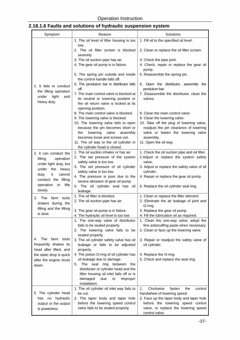
Operation Instruction
-37-
2.18.1.6 Faults and solutions of hydraulic suspension system Symptom Reason Solutions
1. It fails to conduct the lifting operation under light and heavy duty.
1. The oil level of lifter housing is too low.
2. The oil filter screen is blocked severely.
3. The oil suction pipe has air. 4. The gear oil pump is in failure. 5. The spring pin outside and inside
the control handle falls off. 6. The pendulum bar in distributor falls
off. 7. The main control valve is blocked at
its neutral or lowering position or the oil return valve is locked at its opening position.
8. The main control valve is blocked. 9. The lowering valve is blocked. 10. The lowering valve fails to open
because the pin becomes short or the lowering valve assembly becomes loose and screws out.
11. The oil way to the oil cylinder in the cylinder head is closed.
1. Fill oil to the specified oil level. 2. Clean or replace the oil filter screen. 3. Check the pipe joint. 4. Check, repair or replace the gear oil
pump. 5. Reassemble the spring pin. 6. Open the distributor, assemble the
pendulum bar. 7. Disassemble the distributor, clean the
valves. 8. Clean the main control valve. 9. Clean the lowering valve. 10. Take off the plug of lowering valve,
readjust the pin clearance of lowering valve or fasten the lowering valve assembly.
11. Open the oil way.
2. It can conduct the lifting operation under light duty, but under the heavy duty, it cannot conduct the lifting operation or lifts slowly.
1. The oil suction inhales or has air. 2. The set pressure of the system
safety valve is too low. 3. The set pressure of oil cylinder
safety valve is too low. 4. The pressure is poor due to the
severe abrasion of gear oil pump. 5. The oil cylinder seal has oil
leakage.
1. Check the oil suction pipe and oil filter. 2.Adjust or replace the system safety
valve, 3. Adjust or replace the safety valve of oil
cylinder. 4. Repair or replace the gear oil pump. 5. Replace the oil cylinder seal ring.
3. The farm tools shakes during the lifting and the lifting is slow.
1. The oil filter is blocked. 2. The oil suction pipe has air. 3. The gear oil pump is in failure. 4. The hydraulic oil level is too low.
1. Clean or replace the filter element. 2. Eliminate the air leakage of joint and
O-ring. 3. Replace the gear oil pump. 4. Fill the lubrication oil as required.
4. The farm tools frequently shakes its head after lifted, and the static drop is quick after the engine shuts down.
1. The one-way valve of distributor fails to be sealed properly.
2. The lowering valve fails to be sealed properly.
3. The oil cylinder safety valve has oil leakage or fails to be adjusted properly.
4. The piston O-ring of oil cylinder has oil leakage due to damage.
5. The seal ring between the distributor or cylinder head and the lifter housing oil inlet falls off or is damaged due to improper installation.
1. Clean the one-way valve; adopt the fine antiscuffing paste when necessary.
2. Clean or face up the lowering valve. 3. Repair or readjust the safety valve of
oil cylinder. 4. Replace the O-ring. 5. Check and replace the seal ring.
5. The cylinder head has no hydraulic output or the output is powerless.
1. The oil cylinder oil inlet way fails to be cut.
2. The taper body and taper hole before the lowering speed control valve fails to be sealed properly.
1. Clockwise fasten the control handwheel of lowering speed. 2. Face up the taper body and taper hole
before the lowering speed control valve, or replace the lowering speed control valve.
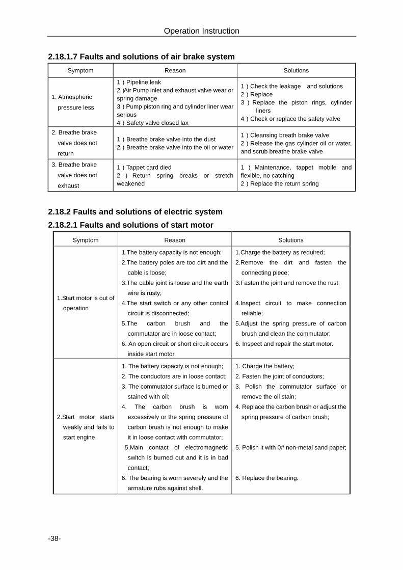
Operation Instruction
-38-
2.18.1.7 Faults and solutions of air brake system
Symptom Reason Solutions
1. Atmospheric
pressure less
1)Pipeline leak 2)Air Pump inlet and exhaust valve wear or spring damage 3)Pump piston ring and cylinder liner wear serious 4)Safety valve closed lax
1)Check the leakage and solutions 2)Replace 3)Replace the piston rings, cylinder
liners 4)Check or replace the safety valve
2. Breathe brake
valve does not
return
1)Breathe brake valve into the dust 2)Breathe brake valve into the oil or water
1)Cleansing breath brake valve 2)Release the gas cylinder oil or water, and scrub breathe brake valve
3. Breathe brake
valve does not
exhaust
1)Tappet card died 2 ) Return spring breaks or stretch weakened
1 ) Maintenance, tappet mobile and flexible, no catching 2)Replace the return spring
2.18.2 Faults and solutions of electric system 2.18.2.1 Faults and solutions of start motor
Symptom Reason Solutions
1.Start motor is out of
operation
1.The battery capacity is not enough;
2.The battery poles are too dirt and the
cable is loose;
3.The cable joint is loose and the earth
wire is rusty;
4.The start switch or any other control
circuit is disconnected;
5.The carbon brush and the
commutator are in loose contact;
6. An open circuit or short circuit occurs
inside start motor.
1.Charge the battery as required;
2.Remove the dirt and fasten the
connecting piece;
3.Fasten the joint and remove the rust;
4.Inspect circuit to make connection
reliable;
5.Adjust the spring pressure of carbon
brush and clean the commutator;
6. Inspect and repair the start motor.
2.Start motor starts
weakly and fails to
start engine
1. The battery capacity is not enough;
2. The conductors are in loose contact;
3. The commutator surface is burned or
stained with oil;
4. The carbon brush is worn
excessively or the spring pressure of
carbon brush is not enough to make
it in loose contact with commutator;
5.Main contact of electromagnetic
switch is burned out and it is in bad
contact;
6. The bearing is worn severely and the
armature rubs against shell.
1. Charge the battery;
2. Fasten the joint of conductors;
3. Polish the commutator surface or
remove the oil stain;
4. Replace the carbon brush or adjust the
spring pressure of carbon brush;
5. Polish it with 0# non-metal sand paper;
6. Replace the bearing.
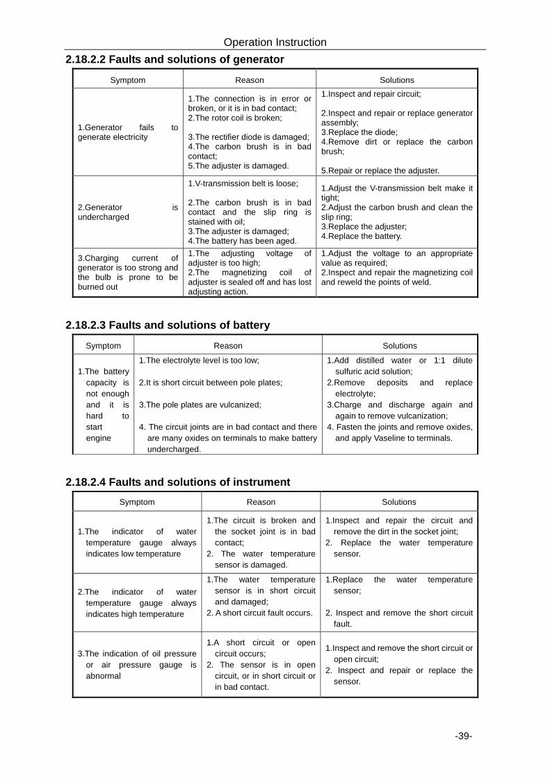
Operation Instruction
-39-
2.18.2.2 Faults and solutions of generator
Symptom Reason Solutions
1.Generator fails to generate electricity
1.The connection is in error or broken, or it is in bad contact; 2.The rotor coil is broken; 3.The rectifier diode is damaged; 4.The carbon brush is in bad contact; 5.The adjuster is damaged.
1.Inspect and repair circuit; 2.Inspect and repair or replace generator assembly; 3.Replace the diode; 4.Remove dirt or replace the carbon brush; 5.Repair or replace the adjuster.
2.Generator is undercharged
1.V-transmission belt is loose; 2.The carbon brush is in bad contact and the slip ring is stained with oil; 3.The adjuster is damaged; 4.The battery has been aged.
1.Adjust the V-transmission belt make it tight; 2.Adjust the carbon brush and clean the slip ring; 3.Replace the adjuster; 4.Replace the battery.
3.Charging current of generator is too strong and the bulb is prone to be burned out
1.The adjusting voltage of adjuster is too high; 2.The magnetizing coil of adjuster is sealed off and has lost adjusting action.
1.Adjust the voltage to an appropriate value as required; 2.Inspect and repair the magnetizing coil and reweld the points of weld.
2.18.2.3 Faults and solutions of battery
Symptom Reason Solutions
1.The battery capacity is not enough and it is hard to start engine
1.The electrolyte level is too low; 2.It is short circuit between pole plates; 3.The pole plates are vulcanized; 4. The circuit joints are in bad contact and there
are many oxides on terminals to make battery undercharged.
1.Add distilled water or 1:1 dilute sulfuric acid solution;
2.Remove deposits and replace electrolyte;
3.Charge and discharge again and again to remove vulcanization;
4. Fasten the joints and remove oxides, and apply Vaseline to terminals.
2.18.2.4 Faults and solutions of instrument Symptom Reason Solutions
1.The indicator of water temperature gauge always indicates low temperature
1.The circuit is broken and the socket joint is in bad contact;
2. The water temperature sensor is damaged.
1.Inspect and repair the circuit and remove the dirt in the socket joint;
2. Replace the water temperature sensor.
2.The indicator of water temperature gauge always indicates high temperature
1.The water temperature sensor is in short circuit and damaged;
2. A short circuit fault occurs.
1.Replace the water temperature sensor;
2. Inspect and remove the short circuit
fault.
3.The indication of oil pressure or air pressure gauge is abnormal
1.A short circuit or open circuit occurs;
2. The sensor is in open circuit, or in short circuit or in bad contact.
1.Inspect and remove the short circuit or open circuit;
2. Inspect and repair or replace the sensor.
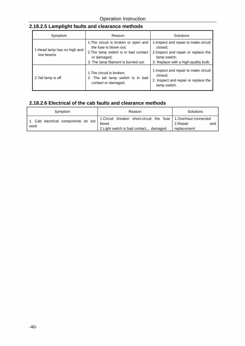
Operation Instruction
-40-
2.18.2.5 Lamplight faults and clearance methods
Symptom Reason Solutions
1.Head lamp has no high and low beams
1.The circuit is broken or open and the fuse is blown out;
2.The lamp switch is in bad contact or damaged;
3. The lamp filament is burned out.
1.Inspect and repair to make circuit closed;
2.Inspect and repair or replace the lamp switch;
3. Replace with a high-quality bulb.
2.Tail lamp is off 1.The circuit is broken; 2. The tail lamp switch is in bad
contact or damaged.
1.Inspect and repair to make circuit closed;
2. Inspect and repair or replace the lamp switch.
2.18.2.6 Electrical of the cab faults and clearance methods
Symptom Reason Solutions
1. Cab electrical components do not work
1.Circuit breaker short-circuit the fuse blows 2.Light switch is bad contact,、damaged
1.Overhaul connected 2.Repair and replacement
Accessories, Spare Parts and Quick-Wearing Parts
-41-
3. Accessories, Spare Parts and Quick-Wearing Parts
3.1 Accessories
The accessories of the tractor include fan heater, pendulum type draw bar, etc.
3.1.1 Fan heater (optional) The fan heater on the tractor is installed in the front upper part in the driver’s cab. The fan
heater switch is installed on the fan heater. The fan heater will be in operation as long as the fan
heater switch is turned on, to make working temperature comfortable in cab.
When it needs to be ventilated in the cab (especially in summer), nothing remains but to shut
off the hot circulating water outlet valve of the fan heater on engine and turn on the fan heater
switch; here the fan of fan heater will be in operation.
The two small flop gates on both left and right sides of fan heater are used to regulate air
stream circulation.
3.1.2 Pendulum type draw bar (optional) The pendulum type draw bar is only used in trailed implement. Rear end of the draw bar is
connected with farm implement by draw pin. The draw bar can swing transversely and it is
relatively easy to connect with farm implement. The draw bar in operation can swing left and right,
but when the tractor draws farm implement to go backward, the locating pin must be inserted in
the hole of draw plate to prevent draw bar swinging.
The height of traction point can be changed by turning draw bar to make traction height
suitable to the farm implement.
Warning: For the tractor with fan heater or air conditioner installed, anti-freezing
solution must be applied to the cooling system of engine to protect fan heater or air conditioner from frost crack.
Accessories, Spare Parts and Quick-Wearing Parts
-42-
3.2 Spare parts
3.2.1 Spare parts Table 3-1 Spare parts
No. Code Name Quantity Remark
1 Spare parts for engine 1
2 SZ1204.58.033A Quick –change couplings (female)
2 Optional, used in 1 pair hydraulic output model
4 Optional, used in 2 pairs hydraulic output model
3
SKB904-1/2-BM Quick-change couplings
2 Optional, used in 1 pair hydraulic output model
4 Optional, used in 2 pairs hydraulic output model
3.2.2 Attached tools Table 3-2 Attached tools
No. Code Name Quantity Remark
1 QB/T 2564.4 Screwdriver for slotted head screws6×150 1 Put in the tool bag
2 QB/T 2564.5 Screwdriver for cross-recessed head screws6×150 1 Put in the tool bag
3 GB/T 3390.1 Socket 18 1 Put in the tool bag
4 GB/T 3390.1 Socket 21 1 Put in the tool bag
5 GB/T 3390.1 Socket 27 1 Put in the tool bag
6 GB/T 3390.3 Sliding handle 1 Put in the tool bag
7 GB/T 3390.4 Connecting rod 250 1 Put in the tool bag
8 JB/T 7942.1 Lever type grease gun A200 1 Put in the tool bag
9 JB/T 3411.47 Pincer B2.5 1 Put in the tool bag
10 JB/T 3411.48 Pincer A2.5 1 Put in the tool bag
11 GB/T 5356 Hexagon socket screw keys 8 1 Put in the tool bag
12 QB/T 3001 Open ended wrenches 8×10 1 Put in the tool bag
13 QB/T 4388 Open ended wrenches 10×12 1 Put in the tool bag
14 QB/T 3001 Open ended wrenches 13×16 1 Put in the tool bag
15 QB/T 3001 Open ended wrenches 18×21 1 Put in the tool bag
16 QB/T 3001 Open ended wrenches 24×27 1 Put in the tool bag
17 QB/T 3001 Open ended wrenches 30×34 1 Put in the tool bag
18 Attached tools for engine 1 From the engine factory
Accessories, Spare Parts and Quick-Wearing Parts
-43-
3.2.3 List of attached documents Table 3-2 List of attached documents
No. Name of documents Quantity Remark
1 Attached technical documents relating to engine 1 From the engine factory, placed in archival bag
2 Product qualification certificate 1 Placed in archival bag
3 Three-guarantee service certificate 1 placed in archival bag
4 Operator’s manual for air conditioner 1 Optional, used for the model with air conditioner
5 Operator’s manual for fan heater 1 Optional, used for the model with fan heater
6 Parts catalogue for tractor 1 placed in archival bag
7 User’s manual for tractor 1 placed in archival bag
8 Engine qualification certificate 1 From the engine factory, placed in archival bag
Note: Attached tools, spare parts and documents relating to engine should be checked
before acceptance according to the diesel engine packing list.
3.3 Quick-wearing parts
The quick-wearing parts of the tractor are described as table 3-4.
Table 3-4 Lists of Quick-Wearing Parts
No. Parts code Parts Name Quantity / unit Remark
1 Safety lever 5A 2
2 Safety lever 10A 8
3 Safety lever 15A 2
4 Safety lever 20A 3
5 Distance light 2-filament bulb 2
6 Steering Bulb 6
7 Location Bulb 6
8 Top working Bulb 4
9 Braking bulb 2
Warning: 1. The above listed spare parts, tools and quick-wearing parts are special parts of the
tractor, so they should be kept well for use in the operation and maintenance of the tractor.
If any part is lost, it may affect the functional service and performance of the tractor.
2. For maintenance, standard fittings as manufacturer requires should be used. If
non-standard fittings are used, it may affect the function, service performance and service
life of the tractor.
Maintenance Instructions
-44-
4. Maintenance Instructions Such technical maintenance measures as regularly cleaning, inspecting, lubricating, adjusting
or replacing some parts of the tractor are generally called technical maintenance. Good technical
maintenance can decelerate the deterioration of technical conditions of parts, reduce faults,
extend service life and make tractor in good condition all the time.
Warning: 1.All maintenance work must be carried out by the operators that are trained
professionally and familiar with features of the tractor, to protect it from damage;
2.The technical maintenance rules must be strictly complied with to make tractor in
normal working and extend its service life.
3.During warranty period, any damage to tractor due to the operators those are
unfamiliar with features of the tractor, carrying out operation and maintenance, or failing to
carry out related maintenance work as required within maintenance period specified by the
manufacturer, will be excluded from related guarantee service of the tractor;
4.It is strictly prohibited to adjust without permission the opening pressure of safety
valve of engine and hydraulic system, the opening pressure of safety valve of air brake
system and the opening pressure of water tank cover, or else a damage may be caused to
the tractor and service performance of the tractor will be affected, and moreover, it will be
excluded from related three-guarantee service.
4.1 Technical maintenance rules The technical maintenance period of the wheeled tractor is determined according to
cumulative operating hours. The technical maintenance includes shift technical maintenance (10h),
50h technical maintenance, 200h technical maintenance, 400h technical maintenance, 800h
technical maintenance, 1600h technical maintenance, special technical maintenance in winter and
technical maintenance for long-time storage.
4.1.1 Shift technical maintenance Ø Remove the dust and oil stain on the tractor;
Ø Inspect and tighten external fasteners of tractor; if there is any looseness, it should be
fastened in time, in particular the fastening bolts of front and rear wheels;
Ø Inspect the liquid level of engine oil sump, water tank, fuel tank, hydraulic steering tank,
travel brake oil tank and hydraulic lifter, and inject fuel or water if not enough; before the
liquid level of oil sump is inspected, the tractor must be parked on a horizontal ground
Maintenance Instructions
-45-
and the engine stops work 15min;
Ø Inject grease according to table 4-1;
Ø Inspect air pressure of front and rear tires and inflate tires as required if not enough;
Ø Inspect and adjust free travel of main and auxiliary clutches and travel brake pedal;
Ø Inspect whether there are three leakages: air leakage, oil leakage and water leakage; if
there is any leakage, remove it;
Ø Maintain the diesel engine in accordance with the requirements of Routine Shift Technical
Maintenance specified in the Operation and Maintenance Manual for Diesel Engine.
4.1.2 50h technical maintenance Ø Finish the shift technical maintenance;
Ø Inject grease according to table 4-1;
Ø Inspect oil surface of oil bath type air cleaner and remove dust;
Ø Maintain the diesel engine in accordance with the requirements of Primary Technical
Maintenance specified in the Operation and Maintenance Manual for Diesel Engine.
4.1.3 200h technical maintenance Ø Finish the 50h technical maintenance;
Ø Inject grease according to table 4-1;
Ø Replace the lubricating oil of diesel engine oil sump;
Ø Clean and maintain the oil basin of oil bath type air cleaner;
Ø Clean the hydraulic oil filter of lifter, and replace the filter element when necessary;
Ø Maintain the diesel engine in accordance with the requirements of Secondary Technical
Maintenance specified in the Operation and Maintenance Manual for Diesel Engine.
4.1.4 400h technical maintenance Ø Finish the 200h technical maintenance;
Ø Inject grease according to table 4-1;
Ø Inspect the main drive and final drive oil level of front driving axle, and inject oil when
necessary;
Ø Inspect the oil level of transmission system and lifter, and inject oil when necessary;
Ø Inspect the free travel of parking brake handle, and adjust it when necessary;
Ø Clean and maintain the filter of hydraulic steering tank;
Ø Maintain the diesel engine in accordance with the requirements of Secondary Technical
Maintenance specified in the Operation and Maintenance Manual for Diesel Engine.
Maintenance Instructions
-46-
4.1.5 800h technical maintenance Ø Finish the 400h technical maintenance;
Ø Inject grease according to table 4-1;
Ø Replace the transmission hydraulic oil for hydraulic steering system;
Ø Replace the transmission hydraulic oil for transmission system and lifter;
Ø Inspect the valve clearance of diesel engine;
Ø Inspect and adjust the injection pressure of oil injection pump;
Ø Clean and maintain the fuel tank;
Ø Maintain the diesel engine in accordance with the requirements of Tertiary Technical
Maintenance specified in the Operation and Maintenance Manual for Diesel Engine.
4.1.6 1600h technical maintenance
Ø Finish the 800h technical maintenance;
Ø Inject grease according to table 4-1;
Ø Clean and maintain the cooling system of diesel engine;
Ø Replace the main drive and final drive lubricating oil of front driving axle;
Ø Inspect, adjust and maintain the start motor;
Ø Maintain the diesel engine in accordance with the requirements of Tertiary Technical
Maintenance specified in the Operation and Maintenance Manual for Diesel Engine.
4.1.7 Special technical maintenance in winter
Ø Replace with winter lubricating oil and fuel;
Ø The anti-freezing solution must be applied when the air temperature in winter is below
zero;
Ø Prior to shift work, the engine should be started according to winter requirements;
Ø The discharge rate of battery should not be more than 25% and the battery should keep a
relatively high charge rate;
Ø After end of operation, the tractor should be parked in a warm shed that takes shelter
from wind.
4.1.8 Technical maintenance for long-time storage
If the storage period of tractor is less than one month and the replacement period of engine oil
is not more than 100 operating hours, special protective measures need not to be taken. If the
storage period of tractor is more than one month, special technical maintenance must be carried
out in accordance with “5 Storage” in this manual.
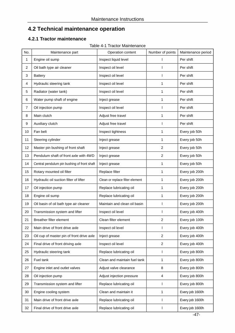
Maintenance Instructions
-47-
4.2 Technical maintenance operation
4.2.1 Tractor maintenance Table 4-1 Tractor Maintenance
No. Maintenance part Operation content Number of points Maintenance period
1 Engine oil sump Inspect liquid level l Per shift
2 Oil bath type air cleaner Inspect oil level l Per shift
3 Battery Inspect oil level l Per shift
4 Hydraulic steering tank Inspect oil level 1 Per shift
5 Radiator (water tank) Inspect oil level 1 Per shift
6 Water pump shaft of engine Inject grease 1 Per shift
7 Oil injection pump Inspect oil level l Per shift
8 Main clutch Adjust free travel 1 Per shift
9 Auxiliary clutch Adjust free travel l Per shift
10 Fan belt Inspect tightness 1 Every job 50h
11 Steering cylinder Inject grease 1 Every job 50h
12 Master pin bushing of front shaft Inject grease 2 Every job 50h
13 Pendulum shaft of front axle with 4WD Inject grease 2 Every job 50h
14 Central pendulum pin bushing of front shaft Inject grease 1 Every job 50h
15 Rotary mounted oil filter Replace filter 1 Every job 200h
16 Hydraulic oil suction filter of lifter Clean or replace filter element 1 Every job 200h
17 Oil injection pump Replace lubricating oil 1 Every job 200h
18 Engine oil sump Replace lubricating oil 1 Every job 200h
19 Oil basin of oil bath type air cleaner Maintain and clean oil basin l Every job 200h
20 Transmission system and lifter Inspect oil level l Every job 400h
21 Breather filter element Clean filter element 2 Every job 100h
22 Main drive of front drive axle Inspect oil level l Every job 400h
23 Oil cup of master pin of front drive axle Inject grease 2 Every job 400h
24 Final drive of front driving axle Inspect oil level 2 Every job 400h
25 Hydraulic steering tank Replace lubricating oil l Every job 800h
26 Fuel tank Clean and maintain fuel tank 1 Every job 800h
27 Engine inlet and outlet valves Adjust valve clearance 8 Every job 800h
28 Oil injection pump Adjust injection pressure 4 Every job 800h
29 Transmission system and lifter Replace lubricating oil l Every job 800h
30 Engine cooling system Clean and maintain it 1 Every job 1600h
31 Main drive of front drive axle Replace lubricating oil l Every job 1600h
32 Final drive of front drive axle Replace lubricating oil l Every job 1600h

Maintenance Instructions
-48-
4.2.2 Technical maintenance operation 4.2.2.1 Battery maintenance
This series tractors use maintenance free battery, usually does not require special
maintenance. Observed hydrometer view hole, sufficient electricity for the green, gray for the
electricity shortage, no electricity for the black. The batteries are in need of additional charge when
the view hole shows the gray; the batteries need to be replaced when the view hole shows the
black.
Warning: 1. When charged, the battery should be away from open flame and indoor air should
be kept unobstructed. After end of charge, the power supply should be cut off
before disconnected from terminals, to prevent striking a flame and causing a fire
or explosion;
2. The battery should be stored in a clean, dry and ventilated warehouse between 0℃
and 40℃. The battery should be handled with care and kept upright
3. The battery terminals and power supply wire joints should be connected firmly to
prevent fusing terminal when starting. The Vaseline should be applied to
connection terminals to protect from oxidation etching;
4. External terminals of battery should be kept clean. The exhaust hole on battery
should be inspected regularly to make it unobstructed;
5. The charge mark on battery should be inspected regularly. The battery should be
charged when necessary.
4.2.2.2 Inspection and maintenance of brake oil tank The brake oil tank is on the right side of hood bracket. Brake fluid oil level should be higher
(10~15) mm than the middle convex plate, when less than this value should identify the causes of
Brake fluid spills and to exclude, and then add Brake fluid.
Note: 1. The correct brake fluid oil level is vital to braking system to normal operation;
2. Hydraulic brake must be synthetic oil,may not be used instead of the brake oil
with alcohol or other mechanical oil。
4.2.2.3 Inspection and maintenance of steering oil tank The steering oil tank is on the engine. Open the tank cover and observe oil level; if the oil is

Maintenance Instructions
-49-
not enough, inspect and find out the cause of oil leakage, and then inject oil. The steering cylinder,
oil pipe and joints should be free from oil leakage, or else the steering may fail to function. The
filter screen in the steering oil tank should be cleaned or replaced regularly.
When inspecting oil level, the breather valve in central position on tank cover should be
inspected to make its rise and fall unobstructed; if affected by oil stain, the breather valve should
be cleaned to remove oil stain.
4.2.2.4 Operation and maintenance of oil bath air cleaner Open hooks of the filter, and then remove the bottom of the oil basin, dump the dirty oil and
clean with kerosene or diesel fuel, while cleaning filter, then add new oil to the oil height, and then
re-installed.
Important matters: Correct operation and maintenance of air cleaner have the direct bearing on service life
of engine, so air cleaner must always be kept clean. During farmland work, air cleaner
should be inspected and cleaned prior to shift work. After maintained, the filter element of
air cleaner must tightly join with air cleaner to avoid any crack and prevent dust or soil
from entering into engine to cause engine scuffing, abnormal wear and severe downward
exhaust, etc.
4.2.2.5 Adjustment of fan belt tightness Press down middle part of fan belt with thumb; the force applied is 29.4~49.0N and the
press-down distance is 15±3 mm. If the requirements are not met, it should be adjusted by the
method below:
Firstly, release the fixing nuts on generator adjusting bracket; secondly, pull the generator
outward to tighten belt; finally, fasten the fixing nuts on generator bracket.
4.2.2.6 Inspection of oil level of engine oil sump and oil replacement Draw out the oil dipstick in the left front of engine oil sump and inspect whether oil level is
between upper and lower scales. If oil level is below lower scale, open the filler cap on engine
timing gear case cap of and inject oil.
Prior to replacement of oil, screw off the oil drain plug at the bottom of oil sump and drain off
dirty oil, and clean it; then inject new oil.
4.2.2.7 Maintenance of the fuel filter As follow picture 4-1. The engine uses two filters series connection, Left for the lst, right for
the 2nd. Paper filter does not allow cleaning, the engine work every 200 hours, replace the lst filter.
When you replacement,you can put 2nd filter installed in the 1st filter, Replaced with a new filter in
2nd filter..
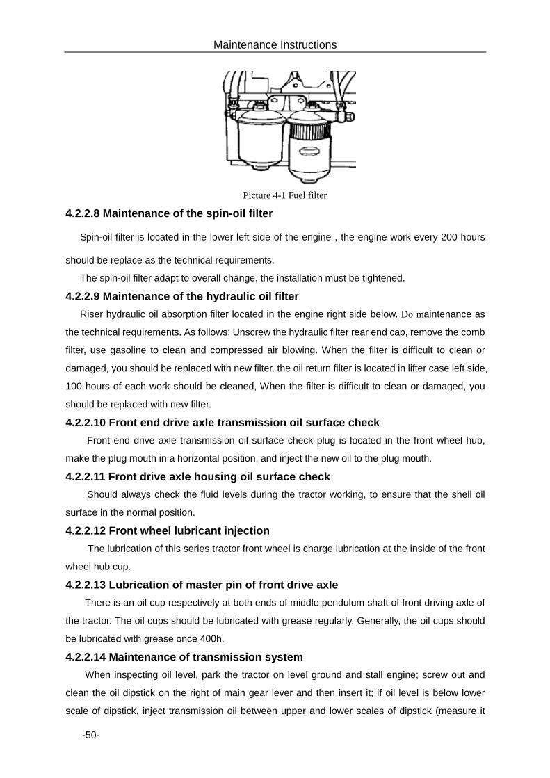
Maintenance Instructions
-50-
Picture 4-1 Fuel filter
4.2.2.8 Maintenance of the spin-oil filter
Spin-oil filter is located in the lower left side of the engine,the engine work every 200 hours
should be replace as the technical requirements.
The spin-oil filter adapt to overall change, the installation must be tightened.
4.2.2.9 Maintenance of the hydraulic oil filter Riser hydraulic oil absorption filter located in the engine right side below. Do maintenance as
the technical requirements. As follows: Unscrew the hydraulic filter rear end cap, remove the comb
filter, use gasoline to clean and compressed air blowing. When the filter is difficult to clean or
damaged, you should be replaced with new filter. the oil return filter is located in lifter case left side,
100 hours of each work should be cleaned, When the filter is difficult to clean or damaged, you
should be replaced with new filter.
4.2.2.10 Front end drive axle transmission oil surface check Front end drive axle transmission oil surface check plug is located in the front wheel hub,
make the plug mouth in a horizontal position, and inject the new oil to the plug mouth.
4.2.2.11 Front drive axle housing oil surface check Should always check the fluid levels during the tractor working, to ensure that the shell oil
surface in the normal position.
4.2.2.12 Front wheel lubricant injection The lubrication of this series tractor front wheel is charge lubrication at the inside of the front
wheel hub cup.
4.2.2.13 Lubrication of master pin of front drive axle There is an oil cup respectively at both ends of middle pendulum shaft of front driving axle of
the tractor. The oil cups should be lubricated with grease regularly. Generally, the oil cups should
be lubricated with grease once 400h.
4.2.2.14 Maintenance of transmission system When inspecting oil level, park the tractor on level ground and stall engine; screw out and
clean the oil dipstick on the right of main gear lever and then insert it; if oil level is below lower
scale of dipstick, inject transmission oil between upper and lower scales of dipstick (measure it
Maintenance Instructions
-51-
5min after injecting engine oil). When replacing lubricating oil, dismount the oil drain plug at the
bottom of transmission case and drain off dirty oil; clean with diesel oil; then screw up the oil drain
plug and inject new engine oil.
4.2.2.15 Maintenance of lifter Park the tractor on level ground; lower lift arm to extreme lower position; stall engine; screw
off the oil dipstick with cover on lifter and inspect oil level; if oil level is below lower scale, inject oil
between upper and lower scales. When replacing hydraulic oil, dismount the plug and drain off
dirty oil; clean and then inject new engine oil as required.
4.2.2.16 Maintenance of fuel tank Park the tractor on level ground and stall engine; dismount the oil drain plug under fuel tank
and drain off the deposits at the bottom of fuel tank. The fuel tank is used to store fuel and deposit
water and impurities, so it should be cleaned regularly in use to remove dirt.
4.2.2.17 Inspection of tire inflation pressure The tire pressure is inspected by barometer and the tire inflation pressure is referred to
technical specifications for tractor. Extremely high or low tire pressure will reduce tire life and have
an adverse impact on travel control of tractor.
4.2.2.18 Maintenance of engine cooling system Engine coolant can be boiled tap water or anti-freezing solution. The validity period of
anti-freezing solution is two years or 1600h. When it is beyond the period of validity, anti-freezing
solution should be replaced and the cooling system should be cleaned; then new anti-freezing
solution is injected.
Precautions for use of radiator:
Ø Before start, inspect whether cooling water in radiator has been filled up and whether
there is water leakage. Inspect whether radiator cover is fastened.
Ø Irregularly inspect radiator core; if it is blocked by weed, dust or oil stain, the weed, dust
or oil stain should be removed.
Ø Regularly remove incrustation scale in cooling system to guarantee heat dissipation of
heat exchange surface.
Ø Regularly inspect thermostat performance to make it in good condition, or else it will
affect circulation of cooling water and reduce cooling effect.
Cleaning of cooling system:
Clean the exterior of radiator. Before cleaning, remove weeds and impurities; then wet the
core body with warm water (or steam); finally dry it with compressed air.
When the radiator is dismounted for cleaning, the detergent is applied and the radiator is
immersed in 1~2% water solution. The solution temperature is 80~100℃ and the radiator is
shaken continuously in solution to remove dirt easily; then the radiator is cleaned with clean water.
Removal of incrustation scale in cooling system: The shift prior to maintenance fills up cooling
Maintenance Instructions
-52-
system with solution prepared with 750g caustic soda and 150g kerosene in 10L water. The
engine runs 5~l 0min at medium speed and the solution stays l0~12h (attention: In winter, must
do heat preservation to prevent freezing); then restart engine and make it run 20min at medium
speed, and then stop engine and drain cleaning liquid. After the engine is cooled, insert water pipe
into water tank to flush it, and here the water drain valve at the bottom of water tank should be
opened. After end of cleaning, close the water drain valve; inject water and make engine run
several minutes, and then drain water. After the engine is cooled, inject new anti-freezing solution
or cooling water as required.
Important matters:
1. In winter, the concentration of anti-freezing solution shall be checked frequently
according to weather conditions. If inappropriate, the solution shall regain normal
concentration immediately. As for tractors free of anti-freeing solution, water shall
be exhausted under the circumstance of idle running of engine when water
temperature drops below 70℃ (Celsius), for fear of frost cracking of machine body
arising by frozen cooling water.
2. To prevent blocking in the inner of water pipe of radiator core, and formation of
incrustant, it is sure that the anti-freezing solution of qualified manufactory must
be used.
3. The radiator must not contact any acid, alkaline or other corrosive substances for
fear of being corroded.
4. Radiator must be installed and washed carefully without damage or bruising.
4.2.2.19 Maintenance of breathers After tractor closes down, breathers will be detached one after another, and washed with
clean diesel oil before carried on tractor The air in the oil circuit must be removed while installation.
4.2.2.20 Exhaust of fuel system When a tractor has been idle for long, diesel filter core is being replaced or when the air in oil
tank is exhausted, air will probably enter oil circuit. The air in fuel system will make engine start-up
difficult. Therefore, it must be removed according to the following steps when the oil tank is full and
oil circuit breaker is in the on position, i.e. loose the air bleed screw of oil filter, put the draw Knob
of oil transfer pump hand pump up and down until there is no bubble in the diesel oil flowing out of
air bleed screw; screw down air bleed screw again and loose air bleed screw on injection pump,
put draw knob of oil transfer pump hand pump up and down until there is no bubble in the diesel oil
flowing gout of air bleed pump; then tighten air bleed screw again.
Important matters: 1. The engine must be provided with high-quality light diesel oil in accordance with
Maintenance Instructions
-53-
operation specification. Generally, 0# light diesel oil is used in summer, while -10#
light diesel oil is used in winter (see diesel engine operation specification for
details). Diesel oil must be pure, and be subject to at least 48-hour purification by
precipitation before use. 2. The lubricated face of ZHB type injection pump shall be frequently checked. The
lubricating oil must be added up to the position of scribed line in time in case of
shortage. Lubricating oil must be replaced once when engine has worked for 200
hours. The grade of lubricating oil used for injection pump must be same with that
used for diesel engine. 4.2.2.21 Exhaust of brake system
Brake system tubing is being demolished, or check the ride (synchronization), the brake
system must exhaust.
Exhaust should follow these steps:
First, fill up the brake oil tank, and slowly depresses the left brake pedal to the end so that the
establishment of brake pressure.
Loose the bleeder plug on the top of brake housing half a lap to allow air to spill. Fastening the
bleeder plug, repeat the above-mentioned actions until there is no air bubble emitting.
Further step on brake pedal to establish oil pressure, when the pedal reaches the normal
travel, the oil pressure fully established (up to the required pressure).
Clean the oil on the drive shaft housing to prevent the paint off.
According to the above-mentioned steps, exhaust the air on the other side of the brake.
Finally, fill up the brake fluid to specified level.
Warning: If the air is not exhausted, the brake system may act up!
4.3 Tractor chassis adjustments
4.3.1 Brake manipulation of the institutions adjustment Brake adjustment is shown as in the picture 4-2.
By adjusting the limit screws 11, to ensure the height(between pedal center and floor)is in
175mm~185mm ;By adjusting the limit screws 3 to ensure the space(between limit screws 3 and
between the brake pump 4)is in 3mm ~ 4mm, so that pedal free stroke in 20 mm~ 26 mm and
pedal working stroke in 110 mm ~ 120 mm. The hand brake operation handle work stroke in
220mm~250mm. Adjust the length of hand brake pull rod, ensure can achieve parking brake within
the working stroke. The adjusting way as below: put the hand brake operation handle in the initial
position (put the operation rod horizontal), take off the pin, draw out the pin shaft 7, loosen the nut
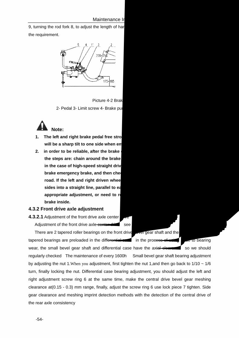
Maintenance Instructions
-54-
9, turning the rod fork 8, to adjust the length of hand brake pull rod until the working stroke meet
the requirement.
Picture 4-2 Brake adjustment
2- Pedal 3- Limit screw 4- Brake pump 5- Brake tank 11- Limit screw
Note: 1. The left and right brake pedal free stroke must be consistent, otherwise the tractor
will be a sharp tilt to one side when emergency braking, thus causing the accident; 2. in order to be reliable, after the brake control restructuring, but also brake testing,
the steps are: chain around the brake pedal, the tractor to open a dry, flat ground, in the case of high-speed straight driving, separation After the primary clutch, with brake emergency brake, and then check the driving wheel parking slip prints in the road. If the left and right driven wheel in the same road on the prints (prints both sides into a straight line, parallel to each other, equal in length), indicating that the appropriate adjustment, or need to re-adjust. If repeatedly adjust well, check the brake inside.
4.3.2 Front drive axle adjustment 4.3.2.1 Adjustment of the front drive axle center drive
Adjustment of the front drive axle center drive,see the picture 4-3,
There are 2 tapered roller bearings on the front drive bevel gear shaft and the left and right two
tapered bearings are preloaded in the differential case,in the process of using,due to bearing
wear, the small bevel gear shaft and differential case have the axial clearance,so we should
regularly checked(The maintenance of every 1600h)。Small bevel gear shaft bearing adjustment
by adjusting the nut 1.When you adjustment, first tighten the nut 1,and then go back to 1/10 ~ 1/6
turn, finally locking the nut. Differential case bearing adjustment, you should adjust the left and
right adjustment screw ring 6 at the same time, make the central drive bevel gear meshing
clearance at(0.15 - 0.3) mm range, finally, adjust the screw ring 6 use lock piece 7 tighten. Side
gear clearance and meshing imprint detection methods with the detection of the central drive of
the rear axle consistency。
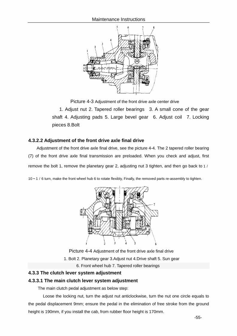
Maintenance Instructions
-55-
Picture 4-3 Adjustment of the front drive axle center drive
1. Adjust nut 2. Tapered roller bearings 3. A small cone of the gear shaft 4. Adjusting pads 5. Large bevel gear 6. Adjust coil 7. Locking pieces 8.Bolt
4.3.2.2 Adjustment of the front drive axle final drive
Adjustment of the front drive axle final drive, see the picture 4-4. The 2 tapered roller bearing
(7) of the front drive axle final transmission are preloaded. When you check and adjust, first
remove the bolt 1, remove the planetary gear 2, adjusting nut 3 tighten, and then go back to 1/
10~1/6 turn, make the front wheel hub 6 to rotate flexibly, Finally, the removed parts re-assembly to tighten.
Picture 4-4 Adjustment of the front drive axle final drive
1. Bolt 2. Planetary gear 3.Adjust nut 4.Drive shaft 5. Sun gear 6. Front wheel hub 7. Tapered roller bearings
4.3.3 The clutch lever system adjustment 4.3.3.1 The main clutch lever system adjustment
The main clutch pedal adjustment as below step:
Loose the locking nut, turn the adjust nut anticlockwise, turn the nut one circle equals to
the pedal displacement 9mm; ensure the pedal in the elimination of free stroke from the ground
height is 190mm, if you install the cab, from rubber floor height is 170mm.
Maintenance Instructions
-56-
4.3.3.2 The vice clutch lever system adjustment Check the joystick system of free stroke should be 3.5 ~ 3.7mm, the manipulation of the
handle measured is 55 ~~ 60mm. When the free stroke of the joystick is less than 1.5mm, should
be adjusted according to the following steps:
loosen the lock nut, counter clockwise rotation adjustment nut, Each turn is equivalent to 1mm
joystick of the trip; Make sure the joystick free stroke is 3.5mm, tighten the locking nut. 4.3.4 Gearbox adjustment 4.3.4.1 Axis adjustment
Use a feeler to measure the axis components of the axial gap initiative satisfies (0.1 to 0.2)
mm range value, Otherwise it should be removed to the driving shaft bearing caps, to ensure that
by adjusting the driving shaft adjustment shim thickness.
4.3.4.2 Vice transmission axis adjustment Use a feeler to measure the vice transmission axis of the axial gap initiative satisfies (0.09 to
0.18) mm range value; otherwise it should be removed vice transmission bearing cap baffle.
Driving shaft by adjusting the vice transmission shaft ends to adjust the shim thickness to ensure. 4.3.5 Adjustment of the rear axle
4.3.5.1 Small bevel gear bearing adjustment The two tapered roller bearings of the small bevel gear shaft are preloaded .During use due to
bearing wear small cone gear shaft axial clearance. When you re-adjust, After the round nut is
tightened, turning the separate rotating pinion single, and made it has preload (1 ~ 2) Nm of
moment of resistance 【you can use the rope wrapped around the small cone gear shaft sleeve
separated put 2 or 3 ring, the spring balance pulling the rope in a small cone axis rotation, The
spring tension is (33 - 66) N】, If out of range ,you should adjust the thickness of the front-end
gasket which on the small bevel gear shaft to meet the preload moment of resistance requires.
4.3.5.2 Differential bearing adjustment Differential left and right bearings are preloaded, during use due to bearing wear; make the
large bevel gear axial clearance increased. Preload decreases, therefore should be checked and
adjustment regularly. When you adjustment , you must first remove the small bevel gear shaft
assembly, Separate measurement of the frictional torque of the rotation of the differential
assembly required is (1.0 ~ 1.5) Nm【you can use the rope wrapped around the differential
caseΦ187 put 2 or 3 ring, rotation of the differential assembly with spring balance pulling the rope,
Spring balance rally is (11 ~ 17) N】If the preload is less than 11N or greater than 17N.,Left / right
bearing on both sides, respectively, an equivalent increase or decrease the adjusting pads ,until
the preload adjusted to the specified range. Differential bearing preload adjustment is completed,
they should be removed parts are reassembled into the differential housing.
Maintenance Instructions
-57-
4.3.5.3 Central drive bevel gear mesh adjustment
The process of using ,the side gear clearance due to gear wear and tear caused by the
increase will not affect the gear work properly. When the bearing wear bevel gear leaving the
original engagement position, in general, just do not affect the normal working of the gears,In the
process of using can not adjust, but when overhaul and gear does not work or replacement of
bearings (Differential bearings and tapered bearings)and spiral bevel gear pair, Meshing
adjustment should be carried out(Should after the bearing preload).
4.3.5.3.1 Check the side gear clearance
Lead sheet inserted into the big and small bevel gear interdental, the gears extruded lead
sheets, then remove the lead piece, taken adjacent to the two lead sheets, measurement chip
thinnest thickness of the two lead(Side gear clearance) should in (0.15 to 0.30) mm range, this
gear the week on a uniform measurement of three-point, choose the mean value. If the
engagement of the backlash is out of range, by adjusting the differential bearing adjustment shim
thickness to achieve. When the gap is large, then the right side of the gasket out plus on the
left. on the contrary, is the left side of the gasket out plus on the right. Correct meshing imprint
should near the tooth height and middle section of cone and was a bit higher than the small end
away from the side edge shall be not less than (3~4) mm, its length not less than 50% of tooth
length, tooth height not less than 50% of the tooth height.
4.3.5.3.2 Check the mesh imprint
On the large bevel gear shaft gear convex coated with a layer of thin the uniform red pigment,
this time the small bevel gear shaft concave force, turn the gear, it can get the small bevel gear
shaft meshing imprint. Correct meshing imprint near the tooth height and middle section of cone
and was a bit higher than the small end away from the side edge shall be not less than (3~4) mm,
its length not less than 50% of tooth length, tooth height not less than 50% of the tooth height.
Adjustment by changing the small cone gear shaft near tooth side to adjust the thickness of the
gasket and make the small bevel gear shaft axial movement and change the pads of both ends
of the differential bearing adjustment to achieve the axial movement to the large bevel gear. In
order not to damage the differential bearing preload, the reduced side of the bearing pads the
number added to the other side of the bearing. so that the left and right bearing adjust shim
thickness remained unchanged.
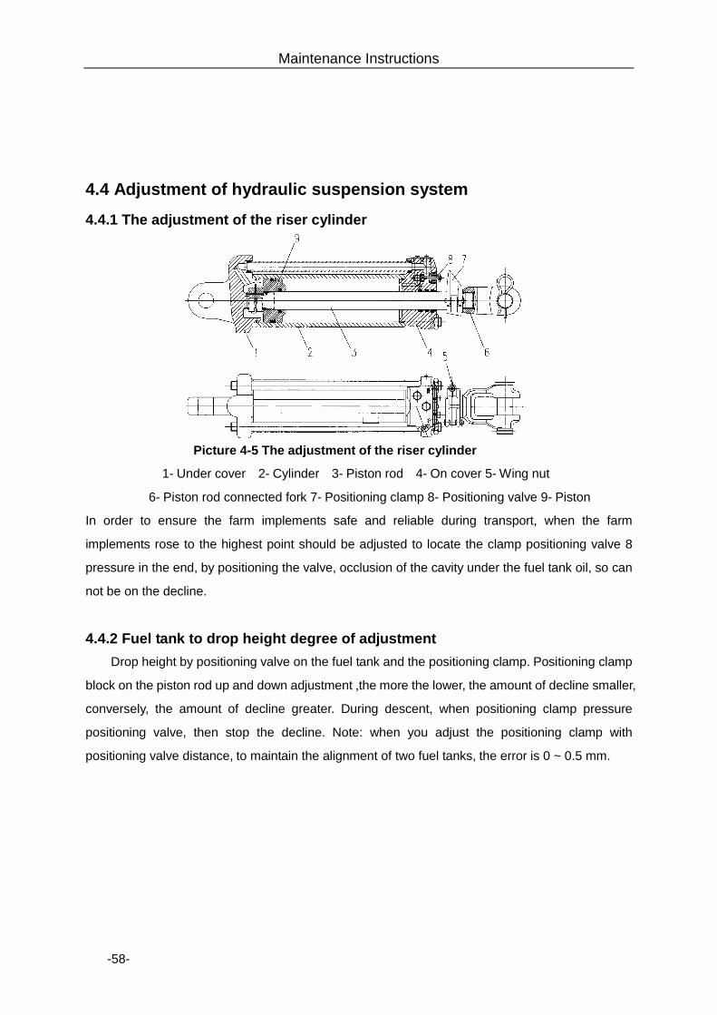
Maintenance Instructions
-58-
4.4 Adjustment of hydraulic suspension system
4.4.1 The adjustment of the riser cylinder
Picture 4-5 The adjustment of the riser cylinder
1- Under cover 2- Cylinder 3- Piston rod 4- On cover 5- Wing nut
6- Piston rod connected fork 7- Positioning clamp 8- Positioning valve 9- Piston
In order to ensure the farm implements safe and reliable during transport, when the farm
implements rose to the highest point should be adjusted to locate the clamp positioning valve 8
pressure in the end, by positioning the valve, occlusion of the cavity under the fuel tank oil, so can
not be on the decline.
4.4.2 Fuel tank to drop height degree of adjustment Drop height by positioning valve on the fuel tank and the positioning clamp. Positioning clamp
block on the piston rod up and down adjustment ,the more the lower, the amount of decline smaller,
conversely, the amount of decline greater. During descent, when positioning clamp pressure
positioning valve, then stop the decline. Note: when you adjust the positioning clamp with
positioning valve distance, to maintain the alignment of two fuel tanks, the error is 0 ~ 0.5 mm.
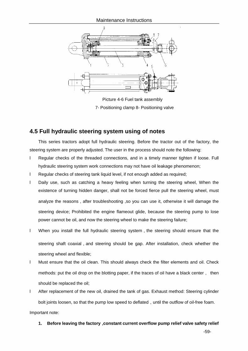
Maintenance Instructions
-59-
Picture 4-6 Fuel tank assembly
7- Positioning clamp 8- Positioning valve
4.5 Full hydraulic steering system using of notes This series tractors adopt full hydraulic steering. Before the tractor out of the factory, the
steering system are properly adjusted. The user in the process should note the following:
l Regular checks of the threaded connections, and in a timely manner tighten if loose. Full
hydraulic steering system work connections may not have oil leakage phenomenon;
l Regular checks of steering tank liquid level, if not enough added as required;
l Daily use, such as catching a heavy feeling when turning the steering wheel, When the
existence of turning hidden danger, shall not be forced fierce pull the steering wheel, must
analyze the reasons,after troubleshooting ,so you can use it, otherwise it will damage the
steering device; Prohibited the engine flameout glide, because the steering pump to lose
power cannot be oil, and now the steering wheel to make the steering failure;
l When you install the full hydraulic steering system,the steering should ensure that the
steering shaft coaxial,and steering should be gap. After installation, check whether the
steering wheel and flexible;
l Must ensure that the oil clean. This should always check the filter elements and oil. Check
methods: put the oil drop on the blotting paper, if the traces of oil have a black center, then
should be replaced the oil;
l After replacement of the new oil, drained the tank of gas. Exhaust method: Steering cylinder
bolt joints loosen, so that the pump low speed to deflated,until the outflow of oil-free foam.
Important note:
1. Before leaving the factory,constant current overflow pump relief valve safety relief

Maintenance Instructions
-60-
pressure has been fine, do not disassemble, adjust;
2. The constant current overflow pumps are precision components, generally not
allowed any demolition, must be removed should be in a clean place. and washing
with clean gasoline or kerosene.
Deposit
-60-
5. Storage
If the tractor should be disused for a long time after finishing the field work or due to other
reasons, it will be necessary to properly seal and store the tractor.
The tractor should be thoroughly cleaned before being sealed and stored. All connectors must
be adjusted and fixed, and the technical service should be done in accordance with working hours,
so that the tractor will be kept in good state.
Important matters: Scientific storage and special maintenance and service are very important during
disuse. Otherwise, the deterioration speed of tractor’s technical state will be higher than
that in working period.
5.1 Reasons for damage of tractor during storage period
Ø Corrosion: during the storage period, the dust and vapor in the air will easily enter into the
machine through gap and orifice, and the parts will be polluted and corroded. Other parts
such as piston, valve, bearing and gear, if they are kept in a position for a long time, they
will lose the protection from lubricant film that flows and has pressure, thus the erosion,
rust, cement blocking or clamping stagnation will occur, and the tractor will be scraped。
Ø Aging: The rubber, plastic and other parts will get aging, degenerated, brittle, corroded,
and decayed or lose effect.
Ø Deformation: plastic deformation occurs in transmission belt, tire and other parts after
they sustain force for long time.
Ø Others: electric parts are affected with damp, the storage battery automatically
discharges, and etc.
5.2 Sealing and storing the tractor
Ø 5.2.1Carefully examine the tractor before sealing and storing it, eliminate the existing
failure, keep good technical state, and clean up the appearance of tractor.
Ø 5.2.2Exhaust the antifreeze and antirust in radiator, air cylinder and water pump, the
engine oil in lubrication system and the engine oil in hydraulic system.
Ø 5.2.3Remove the storage battery, and coat the terminal post with lubricant. Store the
battery in shady room with fine ventilation and at the temperature of more than 10℃.
Ø 5.2.4Exhaust the oil in engine and add new engine oil. Operate the engine throttle for
several minutes, so that the engine oil will accrete to the surface of moving components.
Ø 5.2.5Add grease in each lubricating point.
Deposit
-61-
Ø 5.2.6Coat the electric contacts, connectors and the surface of unpainted metal parts with
dehydrate Vaseline (which should be heated at 100℃ to 200℃).
Ø 5.2.7Loosen the engine fan belt, if necessary, the belt should remove, package and
stored separately, the pulley groove spraying rust inhibitor. If the tractor surface have
stripping, should painting.
Ø 5.2.8Exhausted the diesel of diesel tank and clean the fuel tank
Ø 5.2.9 Use protective materials (such as canvas, tarpaulin, or greaseproof paper, etc.)
seal not closed spout of engine, such as inlet and exhaust ports, to prevent foreign matter,
dust, moisture from entering.
Ø 5.2.10 All joystick should in the neutral position (including the switching of the electrical
system and parking brake), put the tractor front wheels, suspension rods placed in the
lowest position.
Ø 5.2.11Support the tractor off ground with dry wood frame, so that the load can be
removed from tire. Regularly examine the air pressure in tire.
Ø 5.2.12 The tractor should be stored in dry warehouse or shed with good ventilation. It can
not be stored with corrosive goods and liquid. If the tractor is stored outdoor, select the
higher and dry platform, and cover the tractor with tarpaulin.
Ø 5.2.13Clean the parts dismounted from tractor and the tools, pack them and store them in
dry warehouse.
5.3 Service during the period of sealing and storing tractor
Ø All the above mentioned requirements for sealing and storing tractor should be satisfied.
Ø It is necessary to examine whether the corrosion, aging, deformation and other abnormal
phenomenon occur in the tractor and components. The problems should be removed in
time.
Ø The crankshaft of engine should be swerved for 10 to 15 circles every two months, in
order to prevent rust. For the lubricating parts where grease needs to be added, clear
away the old grease and replace new grease.
Ø Start up tractor one every three months, and drive it with low speed for 20 to 30 minutes
to examine whether abnormal phenomenon occurs in each part.
Ø Regularly wipe the dust on the surface of storage battery with dry cloth, and maintain it
regularly by following the Use Manual of Storage Battery. Important matters:
If the tractor is unused for several months or longer, the engine oil should be replaced
at least. Clean the element of engine oil filter. Start up tractor one every three months, and
drive it with low speed for 20 to 30 minutes to examine whether abnormal phenomenon
occurs in each part. Keep the exterior clean and dry.
Deposit
-62-
5.4 Unsealing tractor
Ø Clear away the grease.
Ø Open the closed nozzle, and clean the tractor.
Ø Add coolant, engine oil, diesel, and add lubricant in each lubricating point.
Ø Install the storage battery by following the requirements of Storage Battery Use Manual,
and coat the terminal post with Vaseline.
Ø Clear away the antirust in the groove of fan belt, and mount the belt. Adjust the tightness
degree of transmission belt in line with technical requirements (see the Use and Service
Manual of Engine).
Ø Examine the security of electric circuits and pipelines.
Ø Connect the battery and Vaseline on the terminals.
Ø Operate the tractor as manual rquired.
Notes: Finishing the regular technical maintenance of diesel engine.
Delivery, Acceptance and Transportation
-63-
6.Delivery, Acceptance and Transportation
6.1 Delivery and acceptance
When the user purchases a tractor, he should mainly examine the following aspects:
Ø Whether the documents of the tractor are complete or not.
The documents include: Use and Service Manual of Tractor, Certificate of Quality, Warranty
Card, Catalogue of Tractor’s Parts, List of Accessories (Spare Parts), List of Service Stations for
User and Technical Document of Engine (from the manufacturer of engine).Check whether the
corresponding number on Certificate of Quality, Warranty Card and Technical Document of Engine
tally with the material objects.
Ø Whether the goods of the tractor are complete or not.
Check the goods in line with List of Accessories (Spare Parts), and they should include spare
parts and tools.
Ø Whether the tractor is in good state.
The technical state of tractor may be changed through consignment or movement, thus the
user shall further confirm the tractor’s state.
6.2 Transportation
If the tractor is transported by driving, the traffic rules must be strictly complied with, and the
distance between two vehicles shall be kept as 60m at least. Collision caused by accidents must be
avoided. If the tractor is transported by being loaded on a truck, the following points shall be done:
Ø The tractor should be loaded and unloaded on level ground.
Ø The special unloading deck should be used when loading and unloading the tractor.
Ø The assistant must give guidance at site, and unrelated persons can not be close to the site.
Ø Put the hitch rod on the lower position after loading the tractor, pull the hand brake,
engage the reverse gear, and pull out the startup key.
Ø Keep the tire stable with blocks.
Ø Adjust the rear-view mirror downward, and take it off if necessary (dismount the muffler
as far as possible).
Ø When passing culvert and bridge, caution whether the tractor on truck exceeds the height.
Reduce the speed when turning a corner.
Ø The hand brake should be relieved first when unloading, then engage the forward gear,
and drive the tractor with minimum speed from the truck.
Notes: 1. The brake of truck should be clamped in loading and unloading the tractor, in order
to avoid the tractor rolling or driver dropping risk of truck suddenly start. 2. The tractor should run with minimum speed in loading and unloading, in order to
avoid the rolling or dropping risk of high speed.
Technical Specification
- 64 -
7. Technical Specification
7.1 Product execution standard
Product execution standard:Q/LYBM 005-2011 70-100 Wheeled Tractor series
7.2 Products Indication location
1.The chassis No. of this series are indicated at the left upper side of rear axle housing.
2.The tractor nameplate of this series are indicated at the left side of instrument panel.
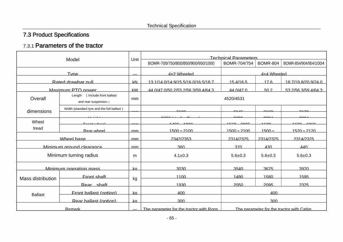
Technical Specification
- 65 -
7.3 Product Specifications
7.3.1 Parameters of the tractor
Model Unit Technical Parameters BOMR-700/750/800/850/900/950/1000 BOMR-704/754 BOMR-804 BOMR-854/904/954/1004
Type — 4×2 Wheeled 4×4 Wheeled
Rated drawbar pull kN 13.1/14.0/14.9/15.5/16.0/16.5/18.7 15.4/16.5 17.6 18.7/19.8/20.9/24.0
Maximum PTO power kW 44.0/47.0/50.2/53.2/56.3/59.4/64.3 44.0/47.0 50.2 53.2/56.3/59.4/64.3
Overall
dimensions
Length (Include front ballast
and rear suspension) mm 4520/4531
Width (standard tyre and the full ballast) mm 2100 2145 2100 2170
Height mm 2700(to the Rops) 2795 2884 2884 Wheel tread
Front wheel mm 1400~1900 1569~2005 1630~
1630~1960 Rear wheel mm 1500~2100 1500~2100 1500~
1520~2120
Wheel base mm 2342/2353 2314/2325 2314/2325 2314/2325
Minimum ground clearance mm 360 370 430 440
Minimum turning radius
m 4.1±0.3 5.6±0.3 5.6±0.3 5.6±0.3
Minimum operation mass kg 3030 3540 3675 3920
Mass distribution Front shaft kg 1100 1490 1580 1595
Rear shaft 1930 2050 2095 2325
Ballast Front ballast (option) kg 400 400
Rear ballast (option) kg 300 300
Remark — The parameter for the tractor with Rops. The parameter for the tractor with Cabin.
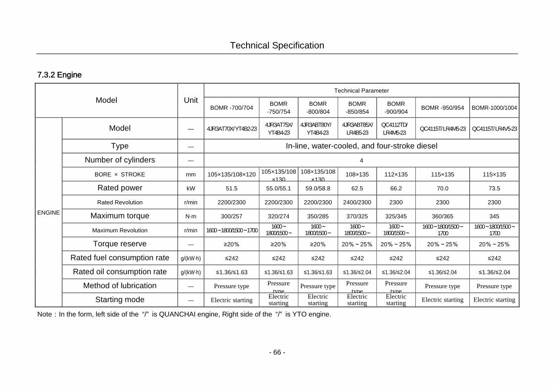
Technical Specification
- 66 -
7.3.2 Engine
Model Unit Technical Parameter
BOMR -700/704 BOMR -750/754
BOMR -800/804
BOMR -850/854
BOMR -900/904
BOMR -950/954 BOMR-1000/1004
ENGINE
Model — 4JR3AT70X/ YT4B2-23 4JR3AT75X/ YT4B4-23
4JR3ABT80Y/ YT4B4-23
4JR3ABT85X/ LR4B5-23
QC4112TD/ LR4M5-23 QC4115T/ LR4M5-23 QC4115T/ LR4V5-23
Type — In-line, water-cooled, and four-stroke diesel
Number of cylinders — 4
BORE × STROKE mm 105×135/108×120 105×135/108×130
108×135/108×130
108×135 112×135 115×135 115×135
Rated power kW 51.5 55.0/55.1 59.0/58.8 62.5 66.2 70.0 73.5
Rated Revolution r/min 2200/2300 2200/2300 2200/2300 2400/2300 2300 2300 2300
Maximum torque N·m 300/257 320/274 350/285 370/325 325/345 360/365 345
Maximum Revolution r/min 1600~1800/1500~1700 1600~1800/1500~
1600~1800/1500~
1600~1800/1500~
1600~1800/1500~
1600~1800/1500~1700
1600~1800/1500~1700
Torque reserve — ≥20% ≥20% ≥20% 20%~25% 20%~25% 20%~25% 20%~25%
Rated fuel consumption rate g/(kW·h) ≤242 ≤242 ≤242 ≤242 ≤242 ≤242 ≤242
Rated oil consumption rate g/(kW·h) ≤1.36/≤1.63 ≤1.36/≤1.63 ≤1.36/≤1.63 ≤1.36/≤2.04 ≤1.36/≤2.04 ≤1.36/≤2.04 ≤1.36/≤2.04
Method of lubrication — Pressure type Pressure type
Pressure type Pressure type
Pressure type
Pressure type Pressure type
Starting mode — Electric starting Electric starting
Electric starting
Electric starting
Electric starting Electric starting Electric starting
Note:In the form, left side of the “/” is QUANCHAI engine, Right side of the “/” is YTO engine.
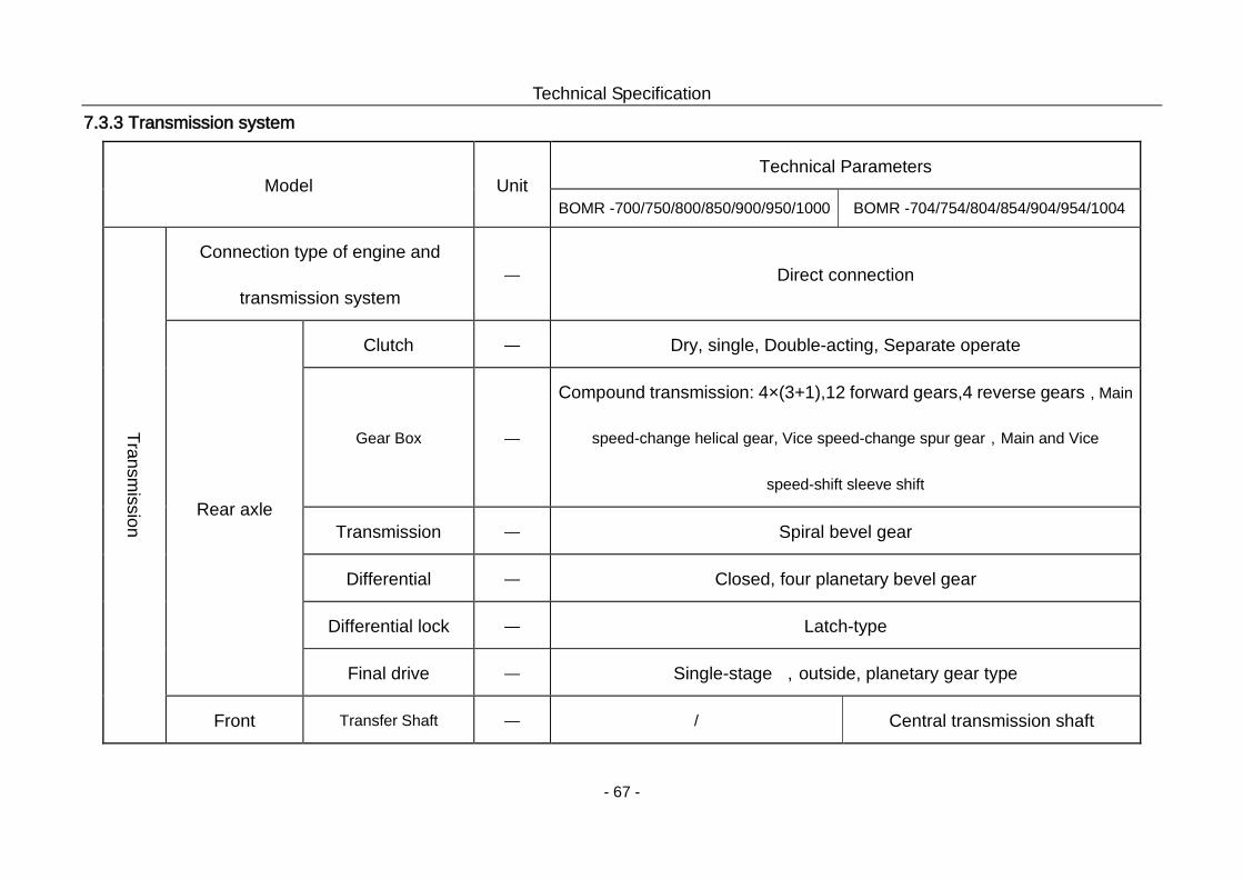
Technical Specification
- 67 -
7.3.3 Transmission system
Model Unit Technical Parameters
BOMR -700/750/800/850/900/950/1000 BOMR -704/754/804/854/904/954/1004
Transmission
Connection type of engine and
transmission system — Direct connection
Rear axle
Clutch — Dry, single, Double-acting, Separate operate
Gear Box —
Compound transmission: 4×(3+1),12 forward gears,4 reverse gears,Main
speed-change helical gear, Vice speed-change spur gear,Main and Vice
speed-shift sleeve shift
Transmission — Spiral bevel gear
Differential — Closed, four planetary bevel gear
Differential lock — Latch-type
Final drive — Single-stage ,outside, planetary gear type
Front Transfer Shaft — / Central transmission shaft
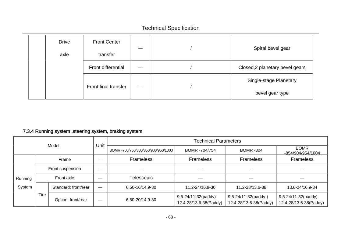
Technical Specification
- 68 -
Drive
axle
Front Center
transfer — / Spiral bevel gear
Front differential — / Closed,2 planetary bevel gears
Front final transfer — / Single-stage Planetary
bevel gear type
7.3.4 Running system ,steering system, braking system
Model Unit Technical Parameters
BOMR -700/750/800/850/900/950/1000 BOMR -704/754 BOMR -804 BOMR -854/904/954/1004
Running
System
Frame — Frameless Frameless Frameless Frameless
Front suspension — — — — —
Front axle — Telescopic — — —
Tire Standard: front/rear — 6.50-16/14.9-30 11.2-24/16.9-30 11.2-28/13.6-38 13.6-24/16.9-34
Option: front/rear — 6.50-20/14.9-30 9.5-24/11-32(paddy) 12.4-28/13.6-38(Paddy)
9.5-24/11-32(paddy) 12.4-28/13.6-38(Paddy)
9.5-24/11-32(paddy) 12.4-28/13.6-38(Paddy)
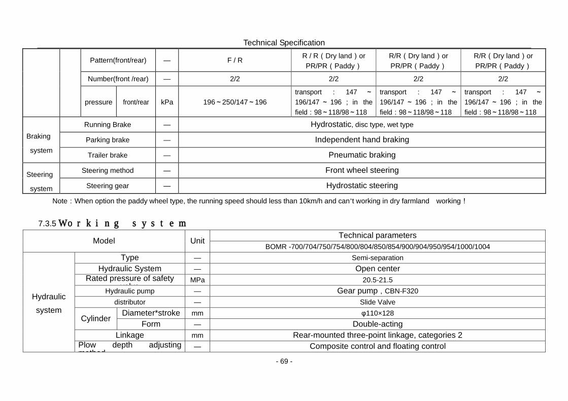
Technical Specification
- 69 -
Pattern(front/rear) — F / R R / R(Dry land)or PR/PR(Paddy)
R/R(Dry land)or PR/PR(Paddy)
R/R(Dry land)or PR/PR(Paddy)
Number(front /rear) — 2/2 2/2 2/2 2/2
pressure front/rear kPa 196~250/147~196 transport : 147 ~196/147 ~ 196 ; in the field:98~118/98~118
transport : 147 ~196/147 ~ 196 ; in the field:98~118/98~118
transport : 147 ~196/147 ~ 196 ; in the field:98~118/98~118
Braking
system
Running Brake — Hydrostatic, disc type, wet type
Parking brake — Independent hand braking
Trailer brake — Pneumatic braking
Steering
system
Steering method — Front wheel steering
Steering gear — Hydrostatic steering
Note:When option the paddy wheel type, the running speed should less than 10km/h and can’t working in dry farmland working! 7.3.5 Working system
Model Unit Technical parameters BOMR -700/704/750/754/800/804/850/854/900/904/950/954/1000/1004
Hydraulic system
Type — Semi-separation Hydraulic System — Open center
Rated pressure of safety valve
MPa 20.5-21.5 Hydraulic pump — Gear pump,CBN-F320
distributor — Slide Valve
Cylinder Diameter*stroke mm φ110×128 Form — Double-acting
Linkage mm Rear-mounted three-point linkage, categories 2 Plow depth adjusting method
— Composite control and floating control
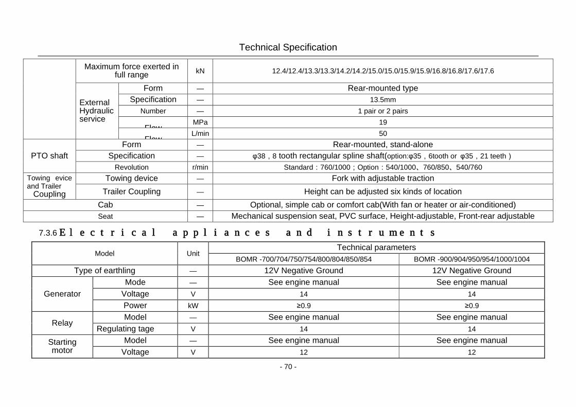
Technical Specification
- 70 -
Maximum force exerted in full range kN 12.4/12.4/13.3/13.3/14.2/14.2/15.0/15.0/15.9/15.9/16.8/16.8/17.6/17.6
External Hydraulic service
Form — Rear-mounted type Specification — 13.5mm
Number — 1 pair or 2 pairs
Flow MPa 19
Flow L/min 50
PTO shaft Form — Rear-mounted, stand-alone
Specification — φ38,8 tooth rectangular spline shaft(option:φ35,6tooth or φ35,21 teeth) Revolution r/min Standard:760/1000;Option:540/1000、760/850、540/760
Towing evice and Trailer
Coupling
Towing device — Fork with adjustable traction
Trailer Coupling — Height can be adjusted six kinds of location
Cab — Optional, simple cab or comfort cab(With fan or heater or air-conditioned) Seat — Mechanical suspension seat, PVC surface, Height-adjustable, Front-rear adjustable
7.3.6 Electrical appliances and instruments
Model Unit Technical parameters
BOMR -700/704/750/754/800/804/850/854 BOMR -900/904/950/954/1000/1004 Type of earthling — 12V Negative Ground 12V Negative Ground
Generator Mode — See engine manual See engine manual
Voltage V 14 14 Power kW ≥0.9 ≥0.9
Relay Model — See engine manual See engine manual
Regulating tage V 14 14
Starting motor
Model — See engine manual See engine manual Voltage V 12 12
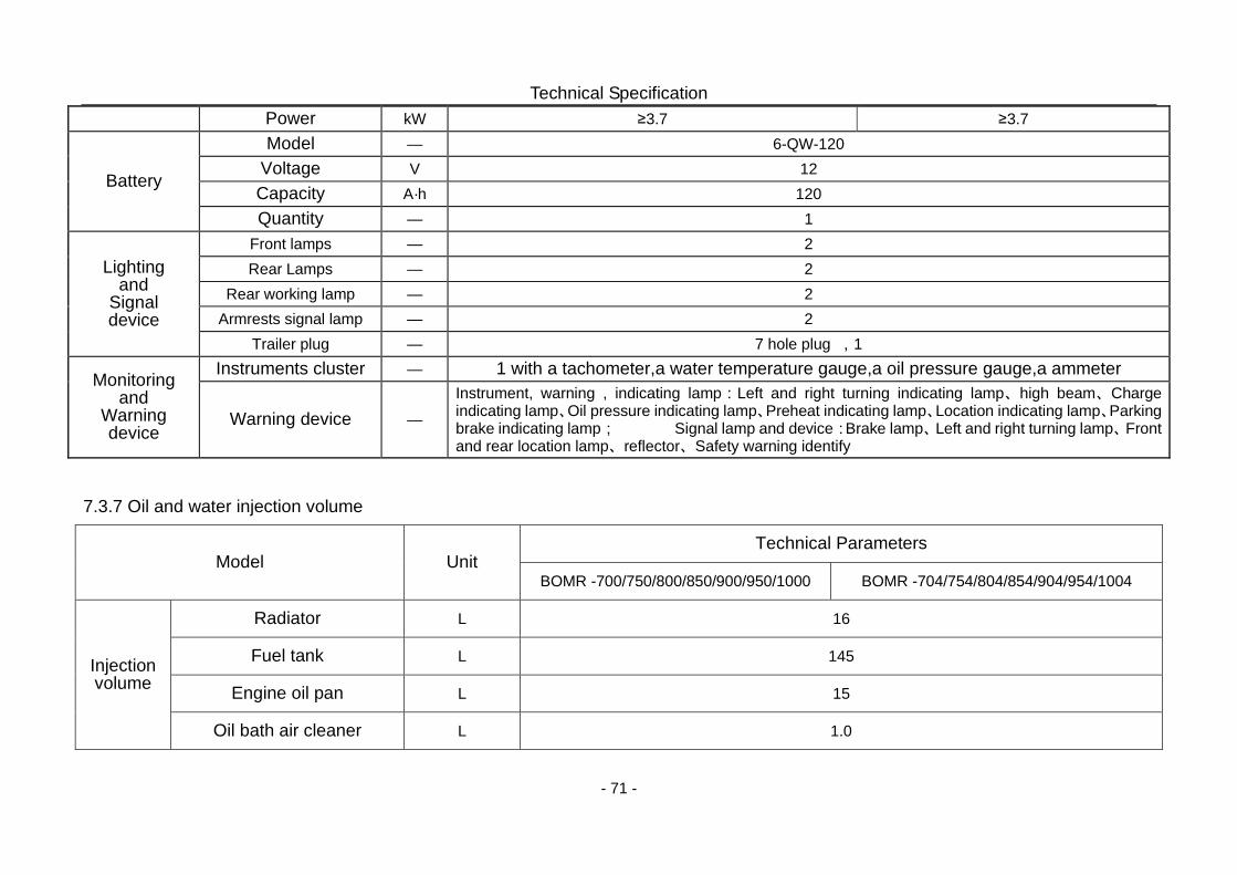
Technical Specification
- 71 -
Power kW ≥3.7 ≥3.7
Battery
Model — 6-QW-120 Voltage V 12 Capacity A·h 120 Quantity — 1
Lighting and
Signal device
Front lamps — 2 Rear Lamps — 2
Rear working lamp — 2 Armrests signal lamp — 2
Trailer plug — 7 hole plug ,1
Monitoring and
Warning device
Instruments cluster — 1 with a tachometer,a water temperature gauge,a oil pressure gauge,a ammeter
Warning device — Instrument, warning , indicating lamp:Left and right turning indicating lamp、high beam、Charge indicating lamp、Oil pressure indicating lamp、Preheat indicating lamp、Location indicating lamp、Parking brake indicating lamp; Signal lamp and device:Brake lamp、Left and right turning lamp、Front and rear location lamp、reflector、Safety warning identify
7.3.7 Oil and water injection volume
Model Unit Technical Parameters
BOMR -700/750/800/850/900/950/1000 BOMR -704/754/804/854/904/954/1004
Injection volume
Radiator L 16
Fuel tank L 145
Engine oil pan L 15
Oil bath air cleaner L 1.0
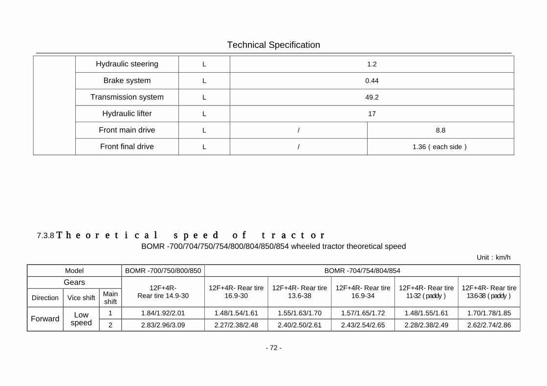
Technical Specification
- 72 -
Hydraulic steering L 1.2
Brake system L 0.44
Transmission system L 49.2
Hydraulic lifter L 17
Front main drive L / 8.8
Front final drive L / 1.36(each side)
7.3.8 Theoretical speed of tractor BOMR -700/704/750/754/800/804/850/854 wheeled tractor theoretical speed
Unit:km/h
Model BOMR -700/750/800/850 BOMR -704/754/804/854 Gears
12F+4R- Rear tire 14.9-30
12F+4R- Rear tire 16.9-30
12F+4R- Rear tire 13.6-38
12F+4R- Rear tire 16.9-34
12F+4R- Rear tire 11-32(paddy)
12F+4R- Rear tire 13.6-38(paddy) Direction Vice shift Main
shift
Forward Low speed
1 1.84/1.92/2.01 1.48/1.54/1.61 1.55/1.63/1.70 1.57/1.65/1.72 1.48/1.55/1.61 1.70/1.78/1.85 2 2.83/2.96/3.09 2.27/2.38/2.48 2.40/2.50/2.61 2.43/2.54/2.65 2.28/2.38/2.49 2.62/2.74/2.86
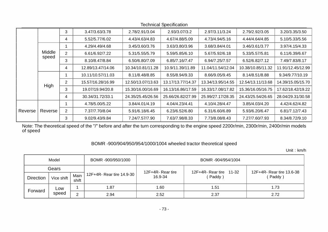
Technical Specification
- 73 -
3 3.47/3.63/3.78 2.78/2.91/3.04 2.93/3.07/3.2 2.97/3.11/3.24 2.79/2.92/3.05 3.20/3.35/3.50 4 5.52/5.77/6.02 4.43/4.63/4.83 4.67/4.88/5.09 4.73/4.94/5.16 4.44/4.64/4.85 5.10/5.33/5.56
Middle speed
1 4.29/4.49/4.68 3.45/3.60/3.76 3.63/3.80/3.96 3.68/3.84/4.01 3.46/3.61/3.77 3.97/4.15/4.33 2 6.61/6.92/7.22 5.31/5.55/5.79 5.59/5.85/6.10 5.67/5.92/6.18 5.33/5.57/5.81 6.11/6.39/6.67 3 8.10/8.47/8.84 6.50/6.80/7.09 6.85/7.16/7.47 6.94/7.25/7.57 6.52/6.82/7.12 7.49/7.83/8.17 4 12.89/13.47/14.06 10.34/10.81/11.28 10.9/11.39/11.89 11.04/11.54/12.04 10.38/10.85/11.32 11.91/12.45/12.99
High
1 10.11/10.57/11.03 8.11/8.48/8.85 8.55/8.94/9.33 8.66/9.05/9.45 8.14/8.51/8.88 9.34/9.77/10.19 2 15.57/16.28/16.99 12.50/13.07/13.63 13.17/13.77/14.37 13.34/13.95/14.55 12.54/13.11/13.68 14.39/15.05/15.70 3 19.07/19.94/20.8 15.30/16.00/16.69 16.13/16.86/17.59 16.33/17.08/17.82 15.36/16.05/16.75 17.62/18.42/19.22 4 30.34/31.72/33.1 24.35/25.45/26.56 25.66/26.82/27.99 25.99/27.17/28.35 24.43/25.54/26.65 28.04/29.31/30.58
Reverse Reverse 1 4.78/5.00/5.22 3.84/4.01/4.19 4.04/4.23/4.41 4.10/4.28/4.47 3.85/4.03/4.20 4.42/4.62/4.82 2 7.37/7.70/8.04 5.91/6.18/6.45 6.23/6.52/6.80 6.31/6.60/6.89 5.93/6.20/6.47 6.81/7.12/7.43 3 9.02/9.43/9.84 7.24/7.57/7.90 7.63/7.98/8.33 7.73/8.08/8.43 7.27/7.60/7.93 8.34/8.72/9.10
Note: The theoretical speed of the "/" before and after the turn corresponding to the engine speed 2200r/min, 2300r/min, 2400r/min models of speed
BOMR -900/904/950/954/1000/1004 wheeled tractor theoretical speed
Unit:km/h
Model BOMR -900/950/1000 BOMR -904/954/1004
Gears 12F+4R- Rear tire 14.9-30 12F+4R- Rear tire
16.9-34 12F+4R- Rear tire 11-32
(Paddy) 12F+4R- Rear tire 13.6-38
(Paddy) Direction Vice shift Main shift
Forward Low speed
1 1.87 1.60 1.51 1.73 2 2.94 2.52 2.37 2.72
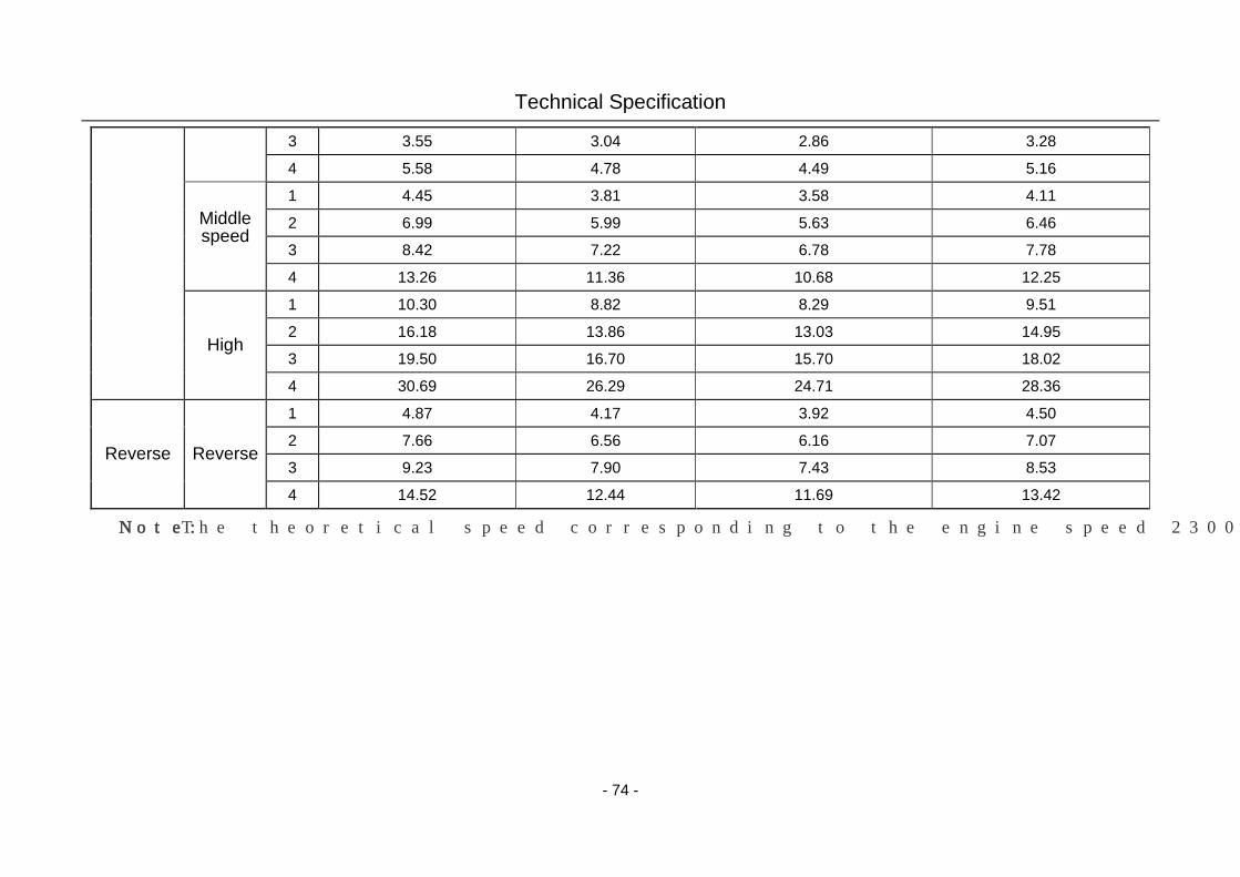
Technical Specification
- 74 -
3 3.55 3.04 2.86 3.28 4 5.58 4.78 4.49 5.16
Middle speed
1 4.45 3.81 3.58 4.11 2 6.99 5.99 5.63 6.46 3 8.42 7.22 6.78 7.78 4 13.26 11.36 10.68 12.25
High
1 10.30 8.82 8.29 9.51 2 16.18 13.86 13.03 14.95 3 19.50 16.70 15.70 18.02 4 30.69 26.29 24.71 28.36
Reverse Reverse
1 4.87 4.17 3.92 4.50 2 7.66 6.56 6.16 7.07 3 9.23 7.90 7.43 8.53 4 14.52 12.44 11.69 13.42
Note: The theoretical speed corresponding to the engine speed 2300r/min.
Disassembly And Disposal
-74-
8.Disassembly and Disposal
When the service life of the entire machine is run out, for the sake of personal safety and
protection of social environment, please transfer the machine to processional recovery company
with permit of disassembly for disposal.
The machine shall be disassembled from up to bottom, from outside to inside. The object of
bulk mass or weight must be disassembled by specialized lifting appliance. Battery shall be
transferred to professional recovery company of battery. The waste engine oil etc. shall be
disposed centrally and properly, instead of being random poured to pollute environment.
Warning: As battery electrolyte is corrosive, be careful not to make it into eyes, on skin or
clothes. If contacting acid liquor, make sure to wash the part infected immediately with
clean water, and rush to hospital for treatment for fear of unexpected injury.
Important matters:
1. The replaced battery acid must not be poured randomly for fear of pollution of
environment.
2. The replaced engine oil, which belongs to waste oil, cannot be discarded randomly
for fear of pollution of environment.
Our company hereby reminds you of possible personal injury arising from improper
arrangement of above things during and after disassembly under the circumstance of absence of
professional disassembly tools and experience in practical operation.
Warning: The object of bulk mass or weight must be disassembled by specialized lifting
appliance! Pay attention to personal safety!
Warranty
-75-
9.Warranty
9.1 Basis of warranty
The warranty of this series of wheeled tractors is based on the following documents and
regulations.
Regulations on Responsibilities for Repair, Replacement and Return of Agricultural Machinery
Products
Law of the People’s Republic of China on Product Quality
Law of the People’s Republic of China on the Consumer Protection
9.2 Situations beyond warranty
According to relevant laws and regulations, there are some situations beyond warranty. See
related chapter sections of Certificate of Guarantee Service for details.
Note: Some conducts may lead to invalidity of warranty conditions. See Certificate of
Guarantee Service for details.
Note: If user modifies tractor randomly or uses it for the purpose other than operation
specification, it will not be within the manufacturer's warranty. Please make sure to pay
attention.
Note:
1. When users receive the maintenance, should show the warranty documents, please
safe keeping;
2. If the tractor have problems, when contact repair, should tell the distributor below
details: tractor model, tractor code, engine type and no., and other nameplate content,
how long have been used, and problem details;
3. Please use the special parts and oil for the tractor.
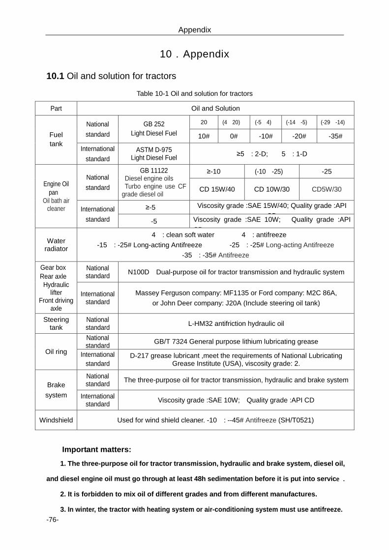
Appendix
-76-
10.Appendix
10.1 Oil and solution for tractors
Table 10-1 Oil and solution for tractors
Part Oil and Solution
Fuel tank
National standard
GB 252 Light Diesel Fuel
>20℃ (4~20)℃ (-5~4)℃ (-14~-5)℃ (-29~-14)℃
10# 0# -10# -20# -35#
International standard
ASTM D-975 Light Diesel Fuel ≥5℃: 2-D; <5℃: 1-D
Engine Oil pan、
Oil bath air cleaner
National standard
GB 11122 Diesel engine oils Turbo engine use CF
grade diesel oil
≥-10℃ (-10~-25)℃ <-25℃
CD 15W/40 CD 10W/30 CD5W/30
International standard
≥-5℃ Viscosity grade :SAE 15W/40; Quality grade :API CD
<-5℃ Viscosity grade :SAE 10W; Quality grade :API CD
Water radiator
>4℃: clean soft water; <4℃: antifreeze >-15℃: -25# Long-acting Antifreeze; >-25℃: -25# Long-acting Antifreeze;
>-35℃: -35# Antifreeze;
Gear box、 Rear axle、 Hydraulic
lifter Front driving
axle
National standard N100D;Dual-purpose oil for tractor transmission and hydraulic system
International standard
Massey Ferguson company: MF1135 or Ford company: M2C 86A, or John Deer company: J20A (Include steering oil tank)
Steering tank
National standard L-HM32 antifriction hydraulic oil
Oil ring
National standard GB/T 7324 General purpose lithium lubricating grease
International standard
D-217 grease lubricant ,meet the requirements of National Lubricating Grease Institute (USA), viscosity grade: 2.
Brake system
National standard The three-purpose oil for tractor transmission, hydraulic and brake system
International standard Viscosity grade :SAE 10W; Quality grade :API CD
Windshield Used for wind shield cleaner. -10℃: --45# Antifreeze (SH/T0521)
Important matters:
1. The three-purpose oil for tractor transmission, hydraulic and brake system, diesel oil,
and diesel engine oil must go through at least 48h sedimentation before it is put into service.
2. It is forbidden to mix oil of different grades and from different manufactures.
3. In winter, the tractor with heating system or air-conditioning system must use antifreeze.

Appendix
-77-
10.2 Tightening torque table of main bolts and nuts
Table 10-2 Tightening torque table of main bolts and nuts
Connection Parts Thread
specification
Tightening
Torque(N·m)
Connecting bolts and nuts between engine and gearbox
housing M12×1.5 90-110
Connecting bolts between gear box and rear axle housing M12×1.5 90-110
Connecting nuts between driving axle housing and rear axle
housing M14×1.5 160-200
Connecting bolts between engine and clutch M10 65-79
Large bevel gear bolts M14×1.5 160-200
Connecting bolts between driving wheel hub and wheel plate M18×1.5 397-457
Connecting bolts between front wheel hub and wheel plate M16×1.5 200-260
Connecting bolts between front support and engine M16 182-245
Front wheel bolts M18×1.5 200-260
Connecting nuts between steering circle and steering column M16×1.5 130-150
Connecting bolts between front rear swing pin bracket and
front bracket M18×1.5 182-245(392)
Connecting bolts between transfer case housing and rear axle
M12×1.5 90-110
Connecting bolts and nuts between lift housing and rear axle
housing M12×1.5 90-110
Note: main bolts and nuts of tractor must be tightened with torque wrench.
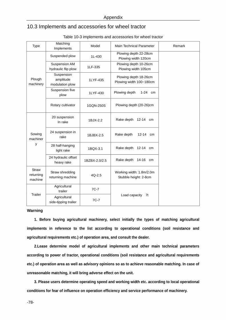
Appendix
-78-
10.3 Implements and accessories for wheel tractor
Table 10-3 implements and accessories for wheel tractor
Type Matching
Implements Model Main Technical Parameter Remark
Plough machinery
Suspended plow 1L-430 Plowing depth 22-28cm Plowing width 120cm
Suspension AM hydraulic flip plow 1LF-335
Plowing depth 10-26cm Plowing width 105cm
Suspension amplitude
modulation plow 1LYF-435
Plowing depth 18-26cm Plowing width 100~180cm
Suspension five plow 1LYF-430 Plowing depth (1-24)cm
Rotary cultivator 1GQN-250S Plowing depth (20-26)cm
Sowing machiner
y
20 suspension In rake 1BJX-2.2 Rake depth(12-14)cm
24 suspension in rake 1BJBX-2.5 Rake depth (12-14)cm
28 half-hanging light rake 1BQX-3.1 Rake depth(12-14)cm
24 hydraulic offset heavy rake 1BZBX-2.0/2.5 Rake depth(14-16)cm
Straw returning machine
Straw shredding returning machine 4Q-2.5
Working width: 1.8m/2.0m Stubble height: 2-8cm
Trailer
Agricultural trailer 7C-7
Load capacity:7t Agricultural side-tipping trailer 7C-7
Warning:
1. Before buying agricultural machinery, select initially the types of matching agricultural
implements in reference to the list according to operational conditions (soil resistance and
agricultural requirements etc.) of operation area, and consult the dealer.
2.Lease determine model of agricultural implements and other main technical parameters
according to power of tractor, operational conditions (soil resistance and agricultural requirements
etc.) of operation area as well as advisory opinions so as to achieve reasonable matching. In case of
unreasonable matching, it will bring adverse effect on the unit.
3. Please users determine operating speed and working width etc. according to local operational
conditions for fear of influence on operation efficiency and service performance of machinery.