Embed Size (px)
Citation preview
1
7 Watts Xbox One Mod Kit Instructions Version 3.3 I.Overview
The modification of your Xbox One controller consists of installing our pre-programmed microchip into the controller’s printed circuit boards (PCBs). If the installation is performed incorrectly, the controller will not function properly. Therefore, the following instructions must be closely followed. This mod should not be attempted without possession of near expert soldering skills. If this is one of your first times soldering, you will almost assuredly destroy the controller, Mod Kit, or both. II.Controller Disassembly
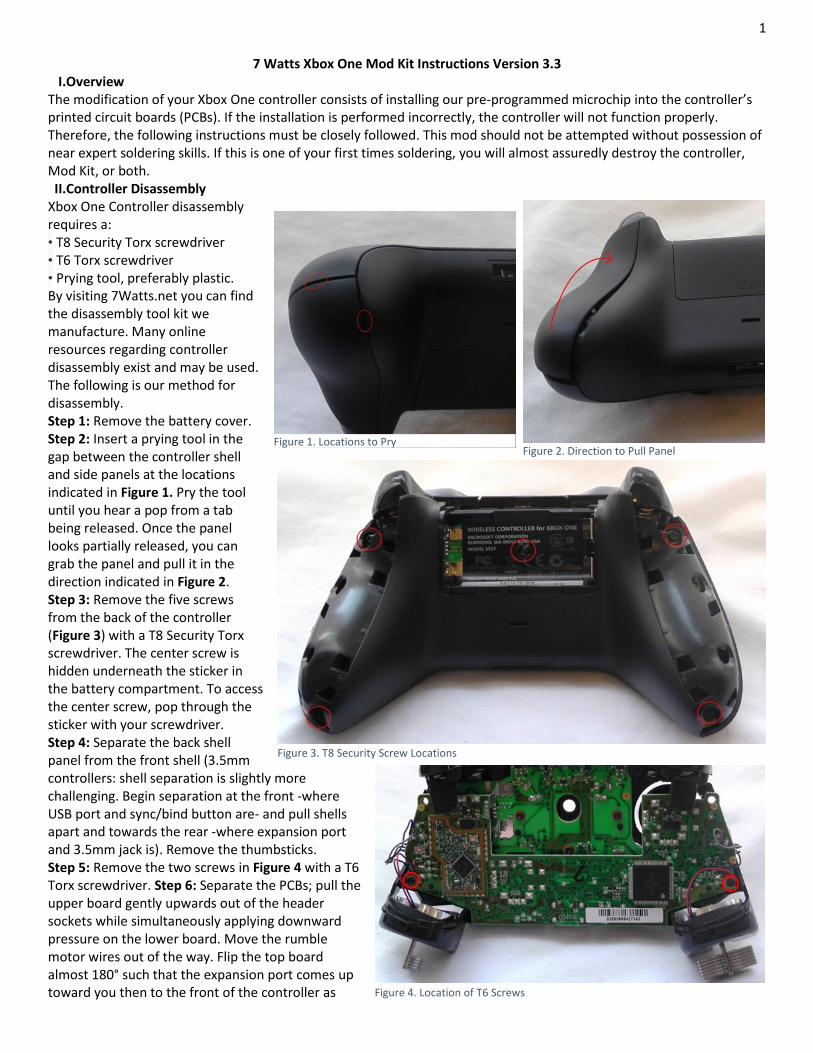
Xbox One Controller disassembly requires a: • T8 Security Torx screwdriver • T6 Torx screwdriver • Prying tool, preferably plastic. By visiting 7Watts.net you can find the disassembly tool kit we manufacture. Many online resources regarding controller disassembly exist and may be used. The following is our method for disassembly. Step 1: Remove the battery cover. Step 2: Insert a prying tool in the gap between the controller shell and side panels at the locations indicated in Figure 1. Pry the tool until you hear a pop from a tab being released. Once the panel looks partially released, you can grab the panel and pull it in the direction indicated in Figure 2. Step 3: Remove the five screws from the back of the controller (Figure 3) with a T8 Security Torx screwdriver. The center screw is hidden underneath the sticker in the battery compartment. To access the center screw, pop through the sticker with your screwdriver. Step 4: Separate the back shell panel from the front shell (3.5mm controllers: shell separation is slightly more challenging. Begin separation at the front -where USB port and sync/bind button are- and pull shells apart and towards the rear -where expansion port and 3.5mm jack is). Remove the thumbsticks. Step 5: Remove the two screws in Figure 4 with a T6 Torx screwdriver. Step 6: Separate the PCBs; pull the upper board gently upwards out of the header sockets while simultaneously applying downward pressure on the lower board. Move the rumble motor wires out of the way. Flip the top board almost 180° such that the expansion port comes up toward you then to the front of the controller as
Figure 1. Locations to Pry Figure 2. Direction to Pull Panel
Figure 3. T8 Security Screw Locations
Figure 4. Location of T6 Screws
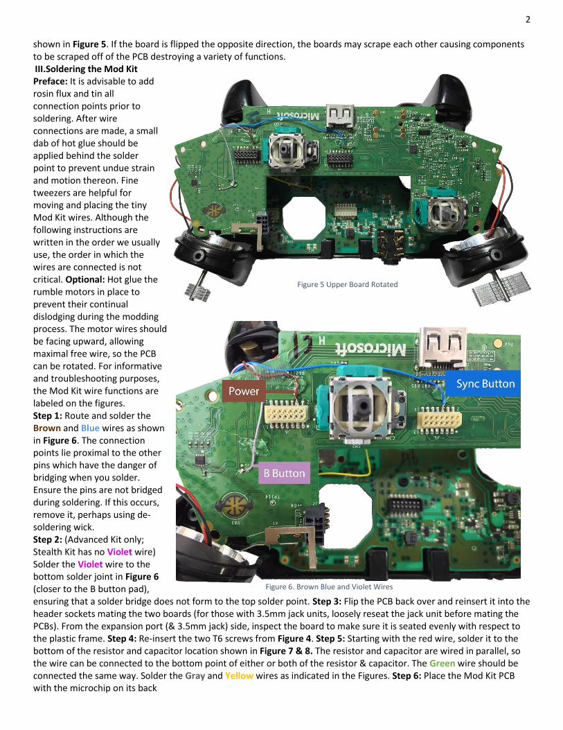
2 shown in Figure 5. If the board is flipped the opposite direction, the boards may scrape each other causing components to be scraped off of the PCB destroying a variety of functions. III.Soldering the Mod Kit Preface: It is advisable to add rosin flux and tin all connection points prior to soldering. After wire connections are made, a small dab of hot glue should be applied behind the solder point to prevent undue strain and motion thereon. Fine tweezers are helpful for moving and placing the tiny Mod Kit wires. Although the following instructions are written in the order we usually use, the order in which the wires are connected is not critical. Optional: Hot glue the rumble motors in place to prevent their continual dislodging during the modding process. The motor wires should be facing upward, allowing maximal free wire, so the PCB can be rotated. For informative and troubleshooting purposes, the Mod Kit wire functions are labeled on the figures. Step 1: Route and solder the Brown and Blue wires as shown in Figure 6. The connection points lie proximal to the other pins which have the danger of bridging when you solder. Ensure the pins are not bridged during soldering. If this occurs, remove it, perhaps using de-soldering wick. Step 2: (Advanced Kit only; Stealth Kit has no Violet wire) Solder the Violet wire to the bottom solder joint in Figure 6 (closer to the B button pad), ensuring that a solder bridge does not form to the top solder point. Step 3: Flip the PCB back over and reinsert it into the header sockets mating the two boards (for those with 3.5mm jack units, loosely reseat the jack unit before mating the PCBs). From the expansion port (& 3.5mm jack) side, inspect the board to make sure it is seated evenly with respect to the plastic frame. Step 4: Re-insert the two T6 screws from Figure 4. Step 5: Starting with the red wire, solder it to the bottom of the resistor and capacitor location shown in Figure 7 & 8. The resistor and capacitor are wired in parallel, so the wire can be connected to the bottom point of either or both of the resistor & capacitor. The Green wire should be connected the same way. Solder the Gray and Yellow wires as indicated in the Figures. Step 6: Place the Mod Kit PCB with the microchip on its back
Figure 6. Brown Blue and Violet Wires
Figure 5 Upper Board Rotated
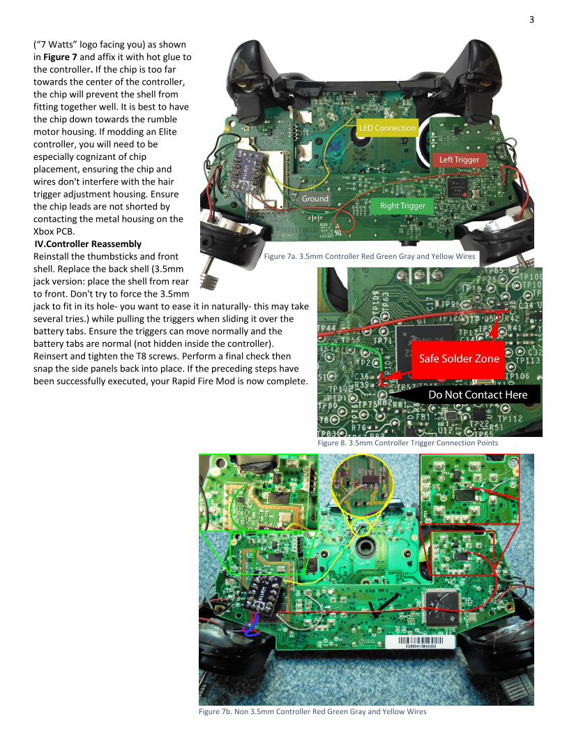
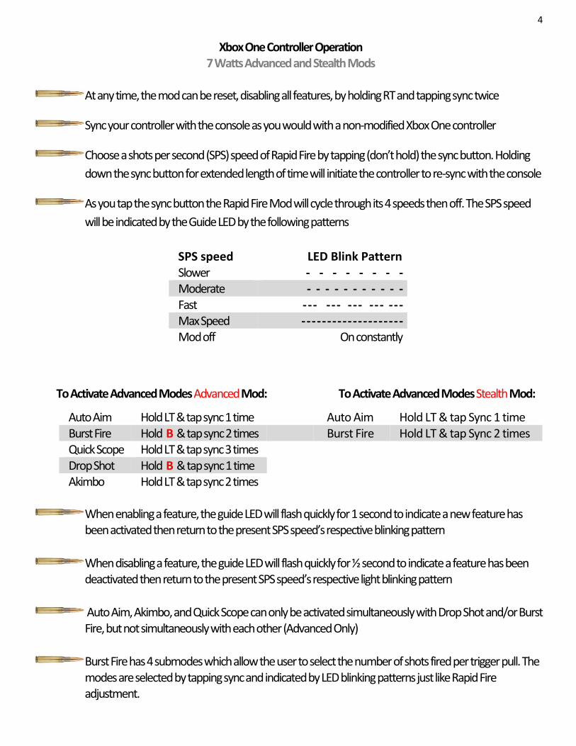
3 (“7 Watts” logo facing you) as shown in Figure 7 and affix it with hot glue to the controller. If the chip is too far towards the center of the controller, the chip will prevent the shell from fitting together well. It is best to have the chip down towards the rumble motor housing. If modding an Elite controller, you will need to be especially cognizant of chip placement, ensuring the chip and wires don't interfere with the hair trigger adjustment housing. Ensure the chip leads are not shorted by contacting the metal housing on the Xbox PCB. IV.Controller Reassembly Reinstall the thumbsticks and front shell. Replace the back shell (3.5mm jack version: place the shell from rear to front. Don't try to force the 3.5mm jack to fit in its hole- you want to ease it in naturally- this may take several tries.) while pulling the triggers when sliding it over the battery tabs. Ensure the triggers can move normally and the battery tabs are normal (not hidden inside the controller). Reinsert and tighten the T8 screws. Perform a final check then snap the side panels back into place. If the preceding steps have been successfully executed, your Rapid Fire Mod is now complete.
Figure 7a. 3.5mm Controller Red Green Gray and Yellow Wires
Figure 7b. Non 3.5mm Controller Red Green Gray and Yellow Wires
Figure 8. 3.5mm Controller Trigger Connection Points
4
Xbox One Controller Operation 7 Watts Advanced and Stealth Mods
At any time, the mod can be reset, disabling all features, by holding RT and tapping sync twice
Sync your controller with the console as you would with a non-modified Xbox One controller
Choose a shots per second (SPS) speed of Rapid Fire by tapping (don’t hold) the sync button. Holding
down the sync button for extended length of time will initiate the controller to re-sync with the console
As you tap the sync button the Rapid Fire Mod will cycle through its 4 speeds then off. The SPS speed
will be indicated by the Guide LED by the following patterns
To Activate Advanced Modes Advanced Mod: To Activate Advanced Modes Stealth Mod:
Auto Aim Hold LT & tap sync 1 time Auto Aim Hold LT & tap Sync 1 time Burst Fire Hold B & tap sync 2 times Burst Fire Hold LT & tap Sync 2 times Quick Scope Hold LT & tap sync 3 times Drop Shot Hold B & tap sync 1 time Akimbo Hold LT & tap sync 2 times
When enabling a feature, the guide LED will flash quickly for 1 second to indicate a new feature has been activated then return to the present SPS speed’s respective blinking pattern
When disabling a feature, the guide LED will flash quickly for ½ second to indicate a feature has been deactivated then return to the present SPS speed’s respective light blinking pattern
Auto Aim, Akimbo, and Quick Scope can only be activated simultaneously with Drop Shot and/or Burst Fire, but not simultaneously with each other (Advanced Only)
Burst Fire has 4 submodes which allow the user to select the number of shots fired per trigger pull. The modes are selected by tapping sync and indicated by LED blinking patterns just like Rapid Fire adjustment.
SPS speed LED Blink Pattern Slower - - - - - - - - Moderate - - - - - - - - - - - Fast - - - - - - - - - - - - - - - Max Speed - - - - - - - - - - - - - - - - - - - - Mod off On constantly
5
Definitions of Terms Automatic Weapon: An automatic firearm is any firearm that will continue to fire so long as the trigger is pressed and held and there is ammunition in the magazine/chamber. Semiautomatic Weapon: Semi-automatic firearms do not automatically fire an additional round until the trigger is released and re-pressed by the person firing the weapon. Stealth Mod: A modified controller with no additional buttons or added external features. A controller may be considered stealth with changed LEDs or aesthetic (graphical) cases. Rapid Fire: The capability of a semiautomatic weapon to fire at the rate of an automatic. Burst Fire: A weapon fires a set number of rounds (usually 2-4) with a single depression of the trigger. Auto Aim: As the trigger is depressed the weapon automatically takes aim through the weapon sights or optic. This substantially enhances the accuracy of the weapon. (Not to be confused with Zombie Auto Aim) Quick Scope: As the Left Trigger (scope button) is slowly depressed, your character aims down the scope. As the Left Trigger is further depressed shots are fired. Akimbo: The ability to simultaneously fire dual wielded weapons by depressing the Right Trigger only. May be used in conjunction with rapid fire. Drop Shot: As the player begins to fire the character drops into the prone position and may continue firing.