Embed Size (px)
Citation preview
Liquid Crystal and Liquid Crystal Polymer based Antenna Chapter 7
152
Chapter 7
7. Liquid Crystal and Liquid Crystal Polymer based Antennas
7.1 Introduction: Depending on the temperature, liquid crystal (LC) phase exists in
between crystalline solid and an isotropic liquid. In this state the material can flow
like a liquid but at the same time molecules have orientation order. A typical LC
molecule has a rod like shape as shown in the Fig 7.1. The size of the molecule is
typically is few nanometres. This shape anisotropy causes anisotropy in terms of
dielectric constant.
Fig 7.1 Typical Liquid Crystal Molecule and its temperature dependency
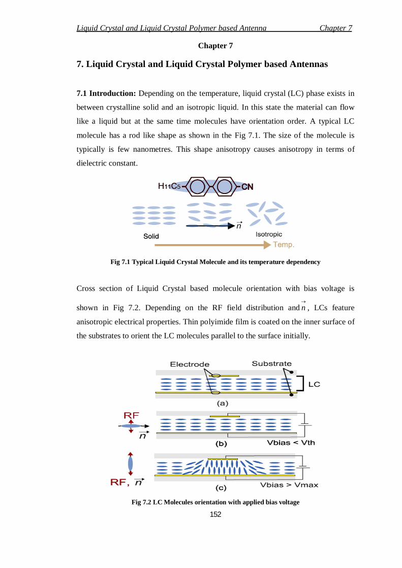
Cross section of Liquid Crystal based molecule orientation with bias voltage is
shown in Fig 7.2. Depending on the RF field distribution and
n , LCs feature
anisotropic electrical properties. Thin polyimide film is coated on the inner surface of
the substrates to orient the LC molecules parallel to the surface initially.
Fig 7.2 LC Molecules orientation with applied bias voltage
Liquid Crystal and Liquid Crystal Polymer based Antenna Chapter 7
153
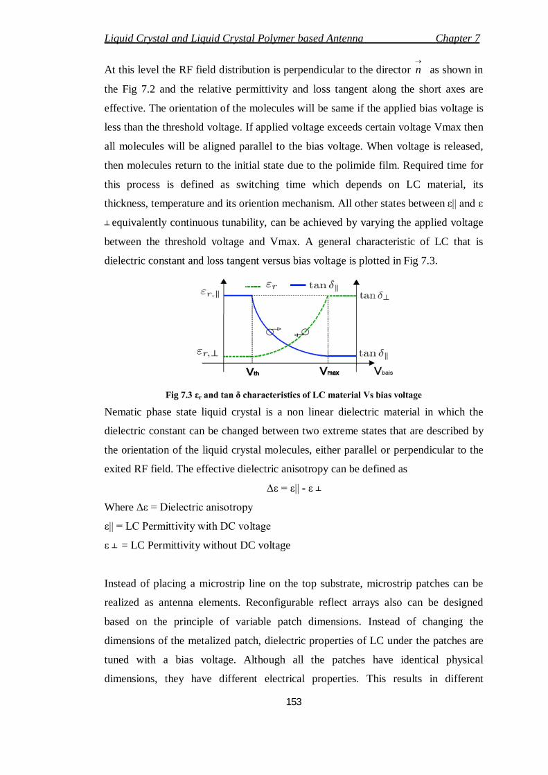
At this level the RF field distribution is perpendicular to the director
n as shown in
the Fig 7.2 and the relative permittivity and loss tangent along the short axes are
effective. The orientation of the molecules will be same if the applied bias voltage is
less than the threshold voltage. If applied voltage exceeds certain voltage Vmax then
all molecules will be aligned parallel to the bias voltage. When voltage is released,
then molecules return to the initial state due to the polimide film. Required time for
this process is defined as switching time which depends on LC material, its
thickness, temperature and its oriention mechanism. All other states between ε|| and ε
┴ equivalently continuous tunability, can be achieved by varying the applied voltage
between the threshold voltage and Vmax. A general characteristic of LC that is
dielectric constant and loss tangent versus bias voltage is plotted in Fig 7.3.
Fig 7.3 εr and tan δ characteristics of LC material Vs bias voltage
Nematic phase state liquid crystal is a non linear dielectric material in which the
dielectric constant can be changed between two extreme states that are described by
the orientation of the liquid crystal molecules, either parallel or perpendicular to the
exited RF field. The effective dielectric anisotropy can be defined as
∆ε = ε|| - ε ┴
Where ∆ε = Dielectric anisotropy
ε|| = LC Permittivity with DC voltage
ε ┴ = LC Permittivity without DC voltage
Instead of placing a microstrip line on the top substrate, microstrip patches can be
realized as antenna elements. Reconfigurable reflect arrays also can be designed
based on the principle of variable patch dimensions. Instead of changing the
dimensions of the metalized patch, dielectric properties of LC under the patches are
tuned with a bias voltage. Although all the patches have identical physical
dimensions, they have different electrical properties. This results in different
Liquid Crystal and Liquid Crystal Polymer based Antenna Chapter 7
154
backscattered phases. Beam forming is possible as different patch lengths from a
feed to the patches are compensated by the preadjusted phases of the patches.
Our intension is to use the liquid crystal and liquid crystal polymer based materials
as substrate materials in the design of microstrip patch antennas. By looking at the
basic operation mechanism in terms of dielectric anisotropy with change in bias
voltage between two electrodes, we can tune the antenna to our desired frequency
and digital controllability will be in our hand. Liquid crystal substrate material can be
attained with LC cavity by placing spherical spacers with small diameter between
two substrates. Although antenna consists of three dielectric layers which are top
substrate, LC layer and bottom substrate the thickness should be maintained low to
attain compactness in size.
7.2 Liquid Crystal Polymer Material
To reduce the overall size, structural complexity and the cost of RF systems,
multilayered substrate materials in which passive elements are Integrated as
distributed elements inside the substrate/packing layers is required. A solution for the
compact integration of these passive components, potentially with embedded active
chips as well is the system-on-package (SOP) approach. In SOP package, connecting
passive and active components on the board and encapsulating the assembly inside of
a robust package are two steps critical to reliable operation of the RF systems. The
package should create an acceptable environmental seal without significantly
affecting the electrical characteristics of the entire circuit. Specifically, the electrical
discontinuities created from the package should create minimal reflections and
minimal inductive or capacitive parasites to avoid throwing off the sensitive
matching circuit of active devices. The most important material characteristics for
use in SOP systems are low electrical loss and excellent seal integrity, generally
specified by permeability to moisture and gases.
So many engineered materials are excellent in performance, but expensive in the
fabrication. For example alumina has dielectric constant 10, which makes it
appropriate for so many antenna applications. In addition, alumina has a high thermal
coefficient of dielectric constant, which means its dielectric constant changes
significantly with temperature. This is why network analyzers, which frequently used
Liquid Crystal and Liquid Crystal Polymer based Antenna Chapter 7
155
alumina substrates, are often left turned on continuously to ensure the dielectric.
Properties of the RF substrates are stabilized. A lamination of these microwave
composites and alumina materials is that none is capable of creating homogeneously
laminated compact 30 integrated RF modules. In other words, these microwave
boards must use other adhesive materials, which have significantly worse water and
gas permeability characteristics to achieve a compact stacked configuration. Fully
hermetic packaging with microwave boards is often required for military
specifications or in satellites, but at much greater financial expense. The term
hermetic means that zero water or gases will permeate the package.
Low temperature co-fired ceramic (LTCC) is the most commonly used ceramic
substrate material for compact RF-design systems. LTCC has very low electrical loss
and can be used in multilayer laminated modules that have densely integrated passive
and active devices stacked and connected vertically to save space and cost. The
major drawback with LTCC is with its high dielectric constant which decreases the
antenna radiation efficiency.
7.3 Liquid Crystal Polymer Substrate
LCP has drawn much attention for its outstanding packaging characteristics.
LCP is low-cost material with the best packing characteristics of any polymer has
generated great interest in using it as a substrate material for mm-wave applications.
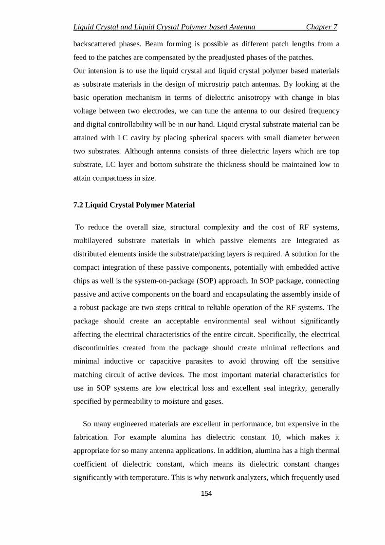
A comparison of these packing characteristics Vs all other polymers are shown in Fig
7.4. Low water absorption should be there for microwave substrate materials for
better stability and reliability. Generally for organic materials the range of water
absorption characteristics is from 0.02% to 0.25% or more.
Fig 7.4 Water and oxygen permeability of different polymers
Liquid Crystal and Liquid Crystal Polymer based Antenna Chapter 7
156
Fig 7.4 shows the water and oxygen permeability of different polymers, in which
liquid crystal polymer is having low water vapour transition. Not only for less water
absorption characteristic, but also for several reasons we prefer LCP material in the
design of RF and microwave modules. Some of the key features are
LCP is having excellent high-frequency electrical properties, stable ɛr and
low loss tangent 0.002-0.004 for frequency < 35GHz.
Quasi-hermetic
Low coefficient of thermal expansion(CTE)
Recyclable
Cost is less
Naturally Non-flammable(Environmentally Friendly)
Flexible
Multilayer all LCP laminations capabilities to create multilayer LCP RF
modules
Relatively low lamination processing temperature(=285 00 c)
Low dielectric constant for use as an efficient antenna substrate.
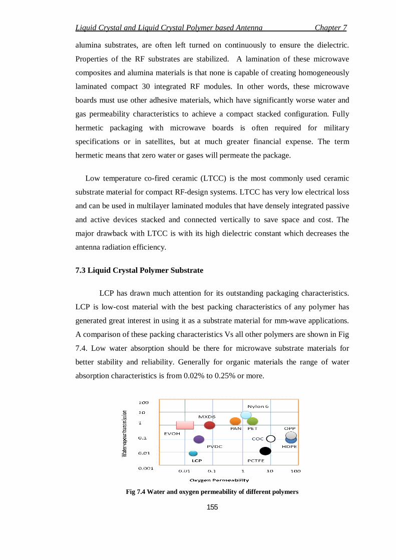
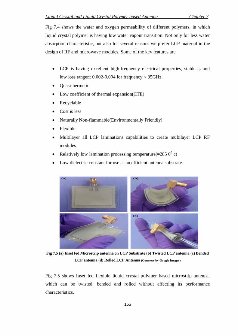
Fig 7.5 (a) Inset fed Microstrip antenna on LCP Substrate (b) Twisted LCP antenna (c) Bended
LCP antenna (d) Rolled LCP Antenna (Courtesy by Google Images)
Fig 7.5 shows Inset fed flexible liquid crystal polymer based microstrip antenna,
which can be twisted, bended and rolled without affecting its performance
characteristics.
Liquid Crystal and Liquid Crystal Polymer based Antenna Chapter 7
157
7.3.1 FELIOS LCP
FELIOS liquid crystal polymer is a flexible circuit board material, which has high
frequency characteristics and low loss tangent after moisture absorption. Now a days
in so many applications like notebook PC’s and smart phones these materials are
been placed instead of traditional materials. The features of this material includes
a) High dimensional stability
b) Good peel strength of copper foil
c) Excellent high frequency properties
7.3.2 Ultralam ® 3850 (Liquid Crystalline Polymer Substrate Material)
Ultralam ® 3850 is the emerging liquid crystalline polymer circuit material from
Rogers Corporation. The features like excellent high frequency properties, good
dimensional stability, external low moisture absorption and flame resistant makes
this as one of the potential substrate material for RF circuit design. So many benefits
are associated with this material, which are listed below
Excellent and stable electrical properties for impedance matching
Uniformity in the thickness for maximum signal integrity
Flexible material for conformal applications i.e. bends easily
In humid environment it maintains the stable mechanical, electrical and
dimensional properties.
The applications includes high speed switches and routers, chip packing, MEM’s,
military satellites, radar sensors, hybrid substrates, handheld RF devices and in the
design of antennas.
0 2 4 6 8 10 122.5
3
3.5
4
4.5Frequency Vs Dielectric constant
Frequency
Die
lect
ric C
onst
ant
LCP at 50 CLCP at 23 CFR4 at 50 CFR4 at 23 C
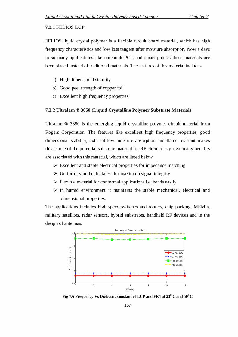
Fig 7.6 Frequency Vs Dielectric constant of LCP and FR4 at 230 C and 500 C
Liquid Crystal and Liquid Crystal Polymer based Antenna Chapter 7
158
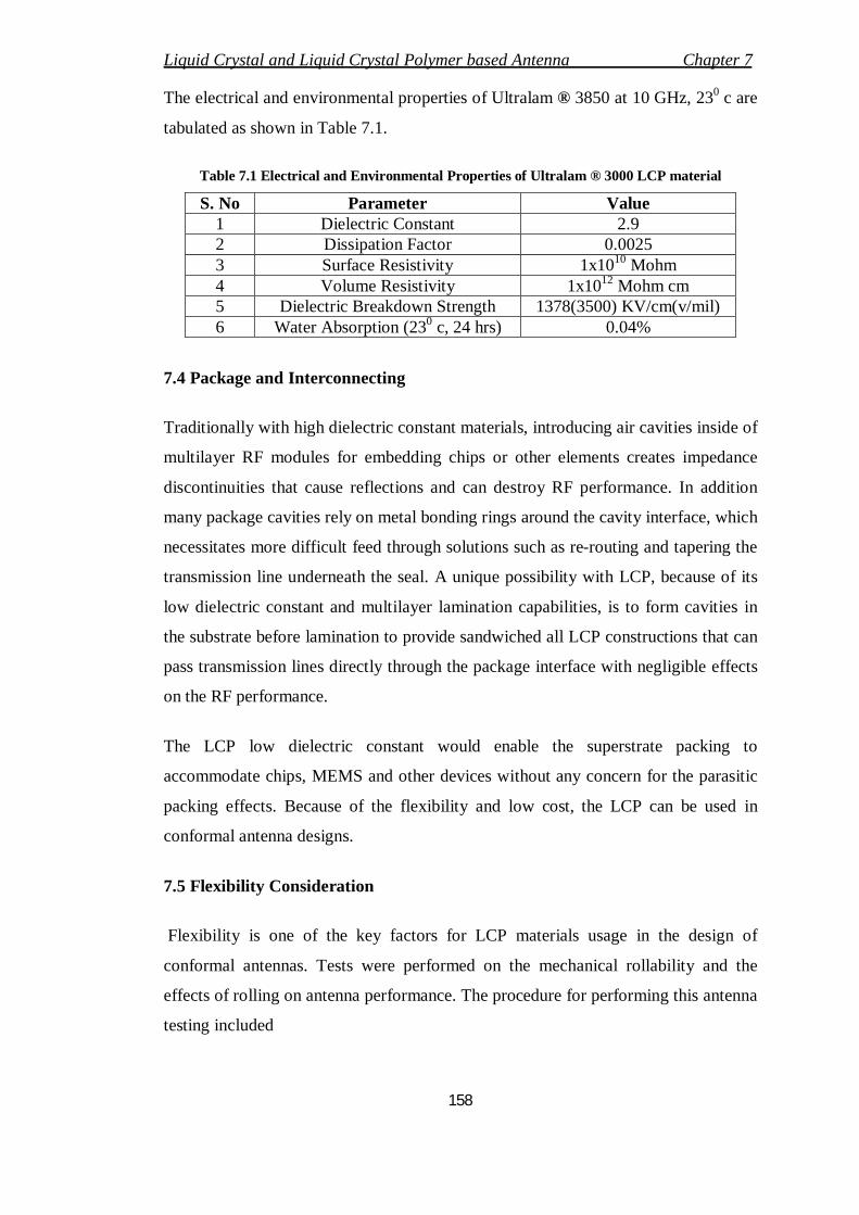
The electrical and environmental properties of Ultralam ® 3850 at 10 GHz, 230 c are
tabulated as shown in Table 7.1.
Table 7.1 Electrical and Environmental Properties of Ultralam ® 3000 LCP material
S. No Parameter Value 1 Dielectric Constant 2.9 2 Dissipation Factor 0.0025 3 Surface Resistivity 1x10¹⁰ Mohm 4 Volume Resistivity 1x10¹² Mohm cm 5 Dielectric Breakdown Strength 1378(3500) KV/cm(v/mil) 6 Water Absorption (230 c, 24 hrs) 0.04%
7.4 Package and Interconnecting
Traditionally with high dielectric constant materials, introducing air cavities inside of
multilayer RF modules for embedding chips or other elements creates impedance
discontinuities that cause reflections and can destroy RF performance. In addition
many package cavities rely on metal bonding rings around the cavity interface, which
necessitates more difficult feed through solutions such as re-routing and tapering the
transmission line underneath the seal. A unique possibility with LCP, because of its
low dielectric constant and multilayer lamination capabilities, is to form cavities in
the substrate before lamination to provide sandwiched all LCP constructions that can
pass transmission lines directly through the package interface with negligible effects
on the RF performance.
The LCP low dielectric constant would enable the superstrate packing to
accommodate chips, MEMS and other devices without any concern for the parasitic
packing effects. Because of the flexibility and low cost, the LCP can be used in
conformal antenna designs.
7.5 Flexibility Consideration
Flexibility is one of the key factors for LCP materials usage in the design of
conformal antennas. Tests were performed on the mechanical rollability and the
effects of rolling on antenna performance. The procedure for performing this antenna
testing included
Liquid Crystal and Liquid Crystal Polymer based Antenna Chapter 7
159
1. Ensuring measurement repeatability when connecting/disconnecting antenna
in the default flat state
2. Performing flexure testing on the antenna, rolling it on to tubes with various
diameters
3. Re-measuring and observing once again the potential differences in
measurement or visual structural changes.
In this procedure we observed that there are very minute changes in the reflection
coefficient of antenna at resonating frequency and in all the cases, there is no
frequency shift is observed.
7.6 Liquid Crystal Patch Antenna
People are attracting towards the development of microwave tuneable devices for
various applications. To develop these devices, liquid crystals are gaining much
attention because of their anisotropic behaviour, which permits to change in the
resonant frequency and reflection phase. By using ferroelectric phase shifters and
varactor diodes, we can implement electronic beam scanning but they will increase
the system complexity and cost.
(a)
(b)
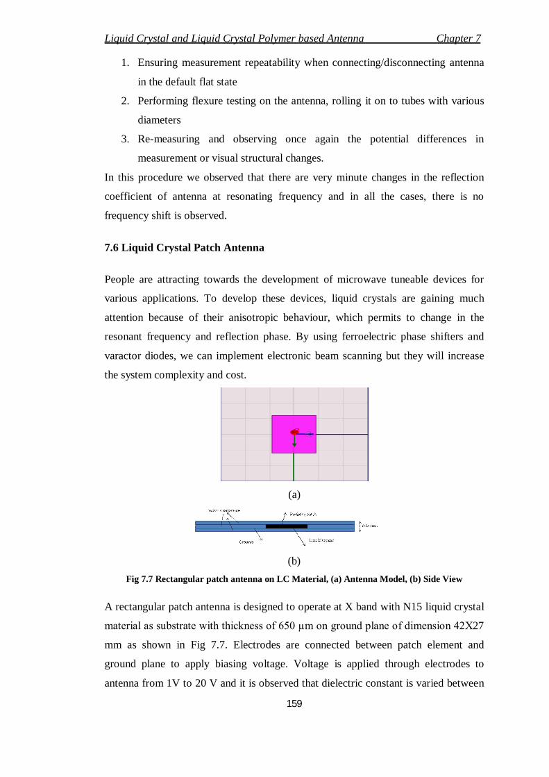
Fig 7.7 Rectangular patch antenna on LC Material, (a) Antenna Model, (b) Side View
A rectangular patch antenna is designed to operate at X band with N15 liquid crystal
material as substrate with thickness of 650 µm on ground plane of dimension 42X27
mm as shown in Fig 7.7. Electrodes are connected between patch element and
ground plane to apply biasing voltage. Voltage is applied through electrodes to
antenna from 1V to 20 V and it is observed that dielectric constant is varied between
Liquid Crystal and Liquid Crystal Polymer based Antenna Chapter 7
160
2.17 to 2.27 in this range. Fig 7.8 shows the change in resonant frequency with the
change in bias voltage and Fig 7.9 shows change in reflection phase with change in
bias voltage and dielectric constant.
9.6 9.8 10 10.2 10.4 10.6 10.8-25
-20
-15
-10
-5
0
Frequency in GHz
Ref
lect
ion
Coe
ffici
ent i
n dB
18 V4 V
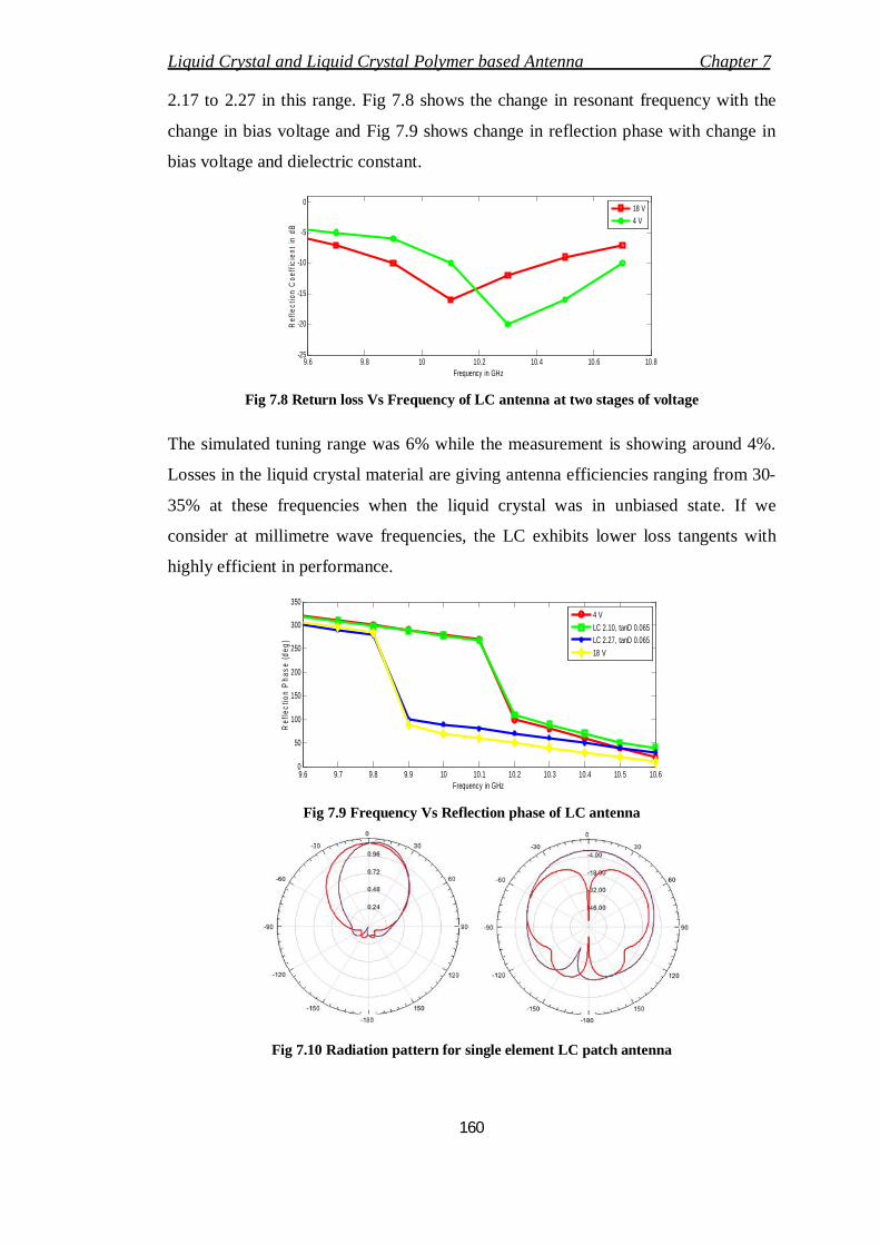
Fig 7.8 Return loss Vs Frequency of LC antenna at two stages of voltage
The simulated tuning range was 6% while the measurement is showing around 4%.
Losses in the liquid crystal material are giving antenna efficiencies ranging from 30-
35% at these frequencies when the liquid crystal was in unbiased state. If we
consider at millimetre wave frequencies, the LC exhibits lower loss tangents with
highly efficient in performance.
9.6 9.7 9.8 9.9 10 10.1 10.2 10.3 10.4 10.5 10.60
50
100
150
200
250
300
350
Frequency in GHz
Ref
lect
ion
Phas
e (d
eg)
4 VLC 2.10, tanD 0.065LC 2.27, tanD 0.06518 V
Fig 7.9 Frequency Vs Reflection phase of LC antenna
Fig 7.10 Radiation pattern for single element LC patch antenna
Liquid Crystal and Liquid Crystal Polymer based Antenna Chapter 7
161
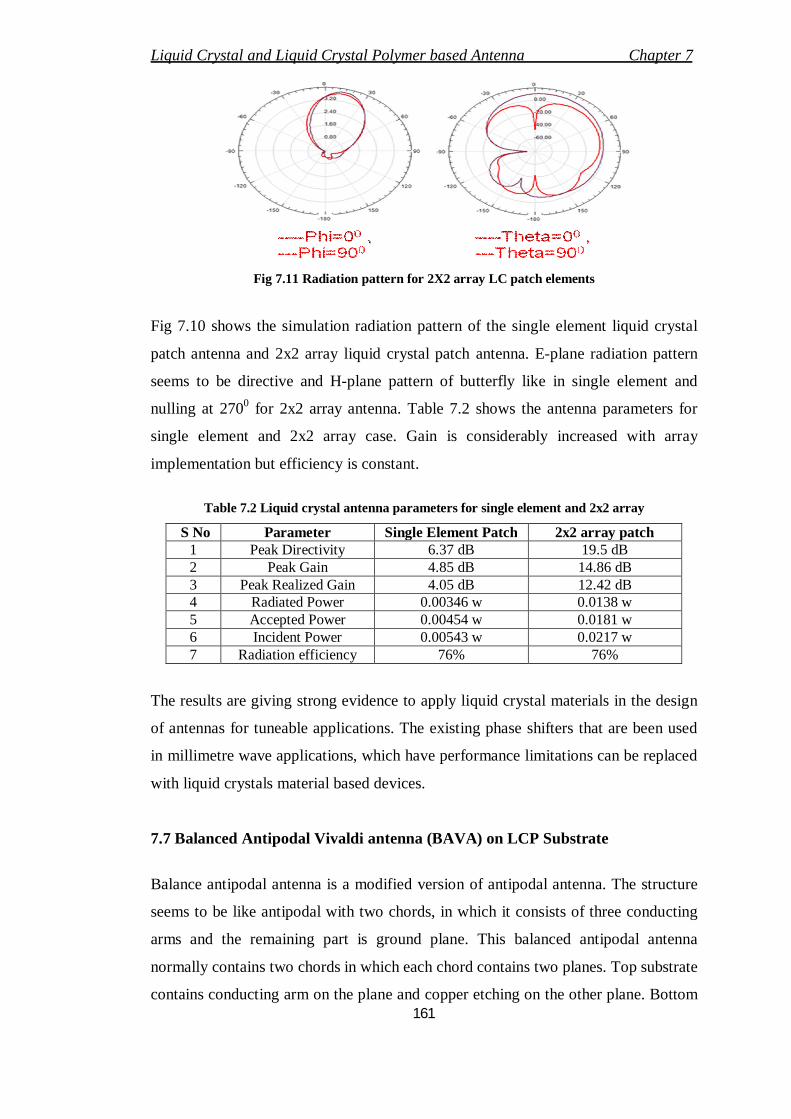
Fig 7.11 Radiation pattern for 2X2 array LC patch elements
Fig 7.10 shows the simulation radiation pattern of the single element liquid crystal
patch antenna and 2x2 array liquid crystal patch antenna. E-plane radiation pattern
seems to be directive and H-plane pattern of butterfly like in single element and
nulling at 2700 for 2x2 array antenna. Table 7.2 shows the antenna parameters for
single element and 2x2 array case. Gain is considerably increased with array
implementation but efficiency is constant.
Table 7.2 Liquid crystal antenna parameters for single element and 2x2 array
S No Parameter Single Element Patch 2x2 array patch 1 Peak Directivity 6.37 dB 19.5 dB 2 Peak Gain 4.85 dB 14.86 dB 3 Peak Realized Gain 4.05 dB 12.42 dB 4 Radiated Power 0.00346 w 0.0138 w 5 Accepted Power 0.00454 w 0.0181 w 6 Incident Power 0.00543 w 0.0217 w 7 Radiation efficiency 76% 76%
The results are giving strong evidence to apply liquid crystal materials in the design
of antennas for tuneable applications. The existing phase shifters that are been used
in millimetre wave applications, which have performance limitations can be replaced
with liquid crystals material based devices.
7.7 Balanced Antipodal Vivaldi antenna (BAVA) on LCP Substrate
Balance antipodal antenna is a modified version of antipodal antenna. The structure
seems to be like antipodal with two chords, in which it consists of three conducting
arms and the remaining part is ground plane. This balanced antipodal antenna
normally contains two chords in which each chord contains two planes. Top substrate
contains conducting arm on the plane and copper etching on the other plane. Bottom
Liquid Crystal and Liquid Crystal Polymer based Antenna Chapter 7
162
substrate contains slot line on one plane and conducting arm on the other plane. The
conducting path is increased in this balanced type reducing the ground plane, surface
waves have been decreased and so cross polarization has been decreased.
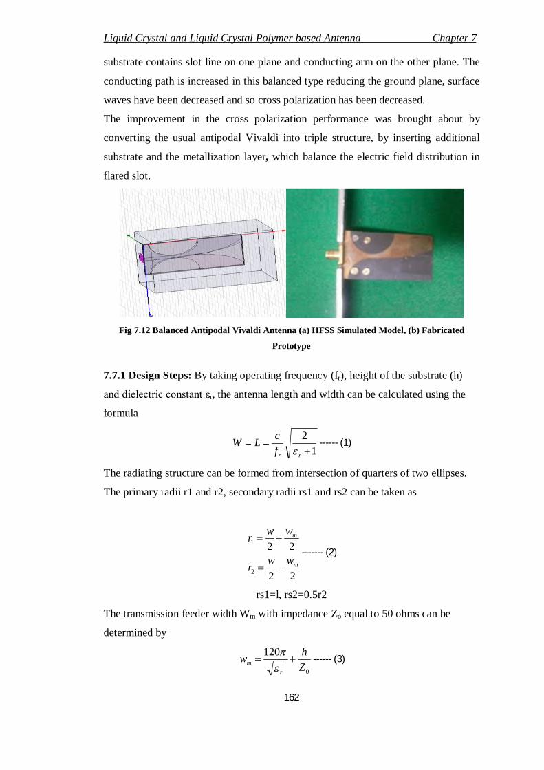
The improvement in the cross polarization performance was brought about by
converting the usual antipodal Vivaldi into triple structure, by inserting additional
substrate and the metallization layer, which balance the electric field distribution in
flared slot.
Fig 7.12 Balanced Antipodal Vivaldi Antenna (a) HFSS Simulated Model, (b) Fabricated
Prototype
7.7.1 Design Steps: By taking operating frequency (fr), height of the substrate (h)
and dielectric constant εr, the antenna length and width can be calculated using the
formula
12
rrf
cLW
------ (1)
The radiating structure can be formed from intersection of quarters of two ellipses.
The primary radii r1 and r2, secondary radii rs1 and rs2 can be taken as
22
22
2
1
m
m
wwr
wwr
------- (2)
rs1=l, rs2=0.5r2
The transmission feeder width Wm with impedance Zo equal to 50 ohms can be
determined by
0
120Zhw
rm
------ (3)
Liquid Crystal and Liquid Crystal Polymer based Antenna Chapter 7
163
The antenna dimensions are listed in table 7.3 Table 7.3 Balanced Antipodal Vivaldi Antenna Dimensions
S. No Parameter Value 1 Antenna Length 52 mm 2 Antenna Width 28.5 mm 3 Slot Width 8 mm 4 Slot Length 36 mm 5 Transmission Line Width, Wm 2.5 mm 6 Transmission Line Length, Lm 16 mm 7 Operating Frequency Range 6-18 GHz 8 Dielectric Material Used LCP with r =2.9 9 Feed Element Length 8 mm
10 Feed Element Width 6 mm
7.7.2 BAVA Parameters
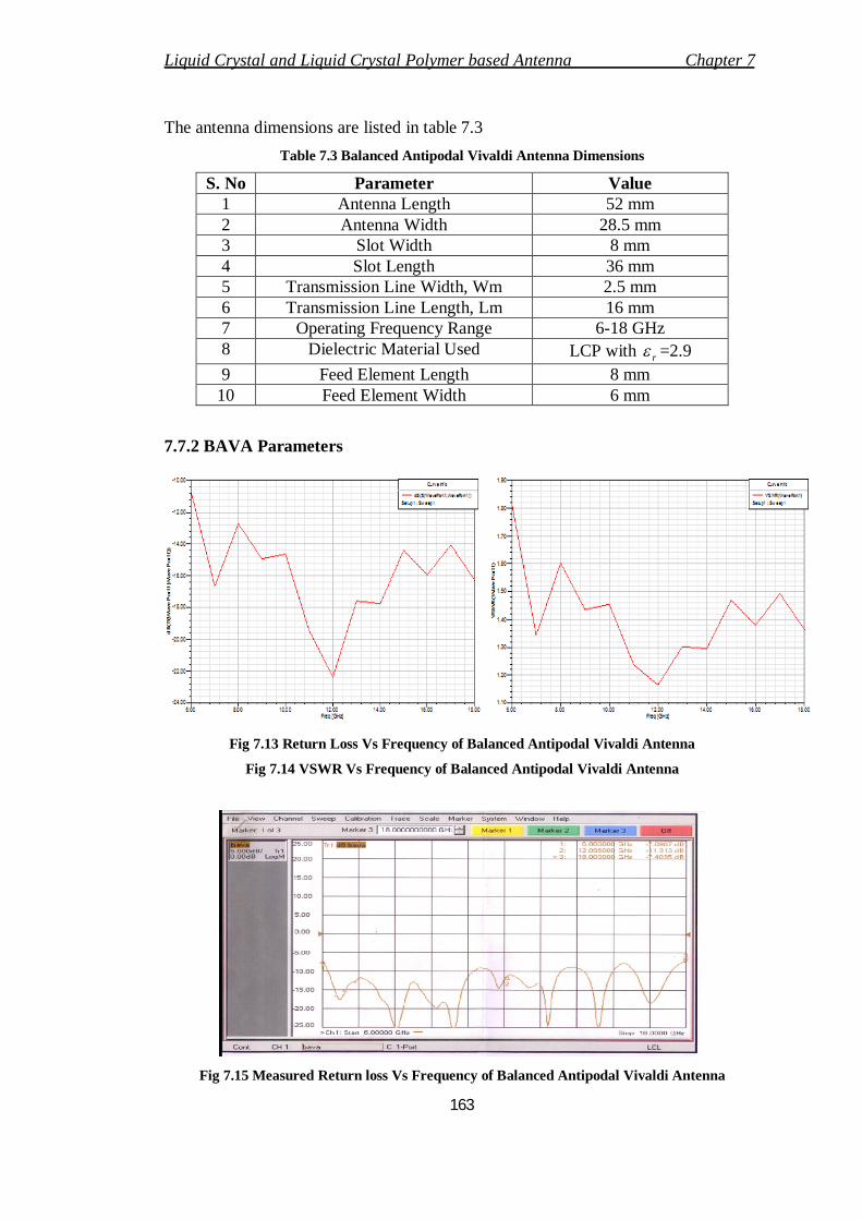
Fig 7.13 Return Loss Vs Frequency of Balanced Antipodal Vivaldi Antenna
Fig 7.14 VSWR Vs Frequency of Balanced Antipodal Vivaldi Antenna
Fig 7.15 Measured Return loss Vs Frequency of Balanced Antipodal Vivaldi Antenna
Liquid Crystal and Liquid Crystal Polymer based Antenna Chapter 7
164
Fig 7.13 shows the frequency Vs return loss of the antenna and Fig 7.14 shows the
VSWR Vs frequency curve. The measured results are taken on Agilent Vector
Network analyzer. Calibration is done using the standard loads supplied by the
manufacturer. Fig 7.15 shows the measured return loss Vs frequency curve on
network analyzer. All the measurements are carried out carefully by not disturbing
the cable setup, which is necessary for accurate measurement.
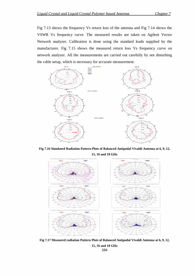
Fig 7.16 Simulated Radiation Pattern Plots of Balanced Antipodal Vivaldi Antenna at 6, 9, 12,
15, 16 and 18 GHz
Fig 7.17 Measured radiation Pattern Plots of Balanced Antipodal Vivaldi Antenna at 6, 9, 12,
15, 16 and 18 GHz
Liquid Crystal and Liquid Crystal Polymer based Antenna Chapter 7
165
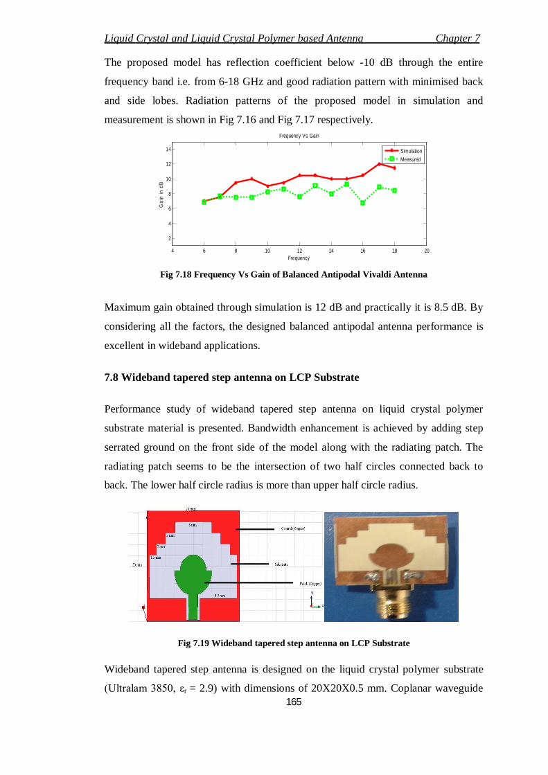
The proposed model has reflection coefficient below -10 dB through the entire
frequency band i.e. from 6-18 GHz and good radiation pattern with minimised back
and side lobes. Radiation patterns of the proposed model in simulation and
measurement is shown in Fig 7.16 and Fig 7.17 respectively.
4 6 8 10 12 14 16 18 20
2
4
6
8
10
12
14
Frequency Vs Gain
Frequency
Gai
n in
dB
SimulationMeasured
Fig 7.18 Frequency Vs Gain of Balanced Antipodal Vivaldi Antenna
Maximum gain obtained through simulation is 12 dB and practically it is 8.5 dB. By
considering all the factors, the designed balanced antipodal antenna performance is
excellent in wideband applications.
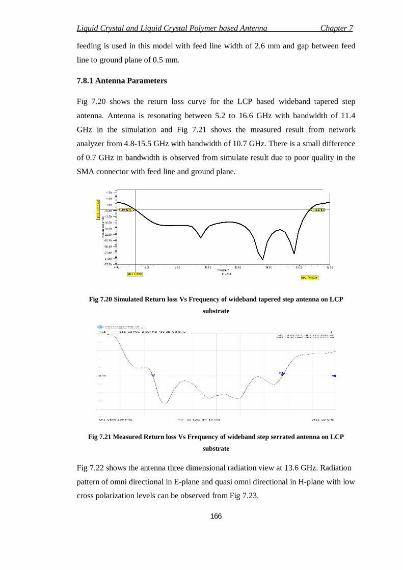
7.8 Wideband tapered step antenna on LCP Substrate
Performance study of wideband tapered step antenna on liquid crystal polymer
substrate material is presented. Bandwidth enhancement is achieved by adding step
serrated ground on the front side of the model along with the radiating patch. The
radiating patch seems to be the intersection of two half circles connected back to
back. The lower half circle radius is more than upper half circle radius.
Fig 7.19 Wideband tapered step antenna on LCP Substrate
Wideband tapered step antenna is designed on the liquid crystal polymer substrate
(Ultralam 3850, εr = 2.9) with dimensions of 20X20X0.5 mm. Coplanar waveguide
Liquid Crystal and Liquid Crystal Polymer based Antenna Chapter 7
166
feeding is used in this model with feed line width of 2.6 mm and gap between feed
line to ground plane of 0.5 mm.
7.8.1 Antenna Parameters
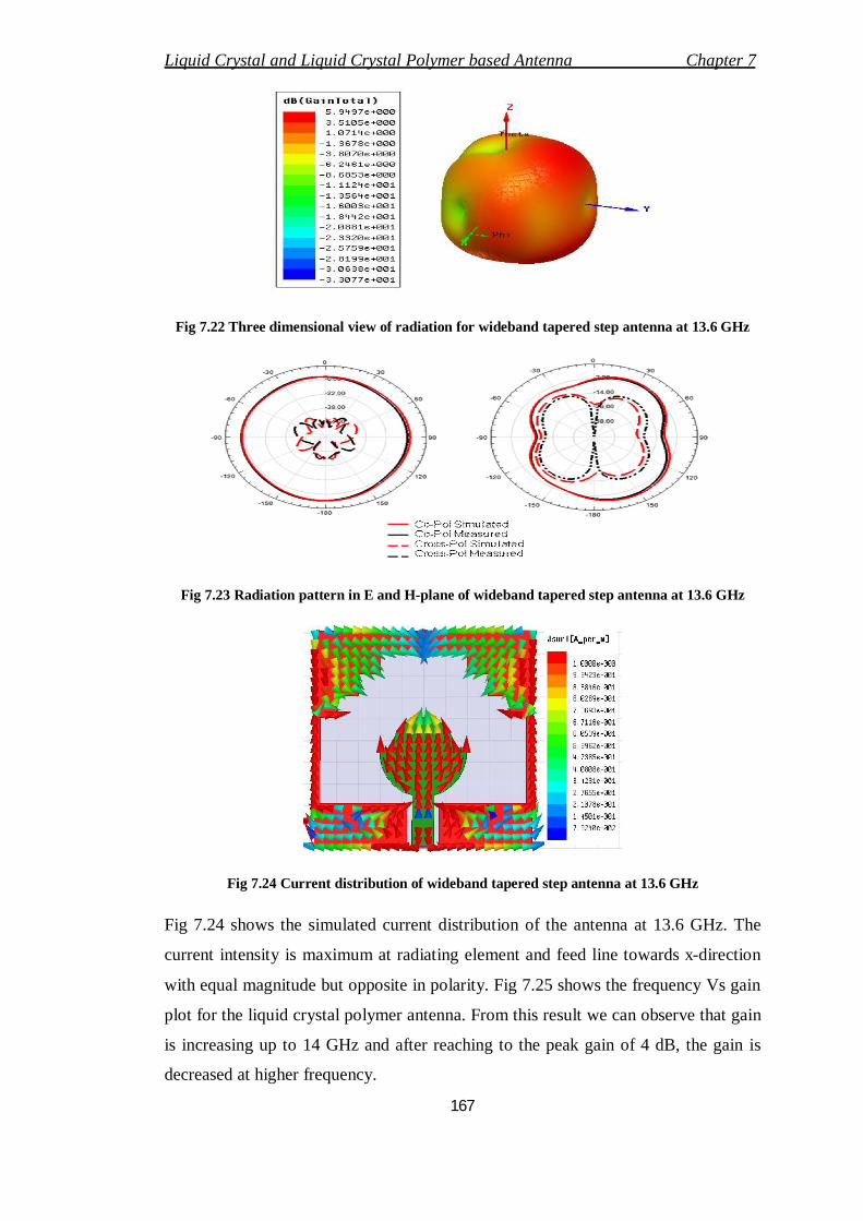
Fig 7.20 shows the return loss curve for the LCP based wideband tapered step
antenna. Antenna is resonating between 5.2 to 16.6 GHz with bandwidth of 11.4
GHz in the simulation and Fig 7.21 shows the measured result from network
analyzer from 4.8-15.5 GHz with bandwidth of 10.7 GHz. There is a small difference
of 0.7 GHz in bandwidth is observed from simulate result due to poor quality in the
SMA connector with feed line and ground plane.
Fig 7.20 Simulated Return loss Vs Frequency of wideband tapered step antenna on LCP
substrate
Fig 7.21 Measured Return loss Vs Frequency of wideband step serrated antenna on LCP
substrate
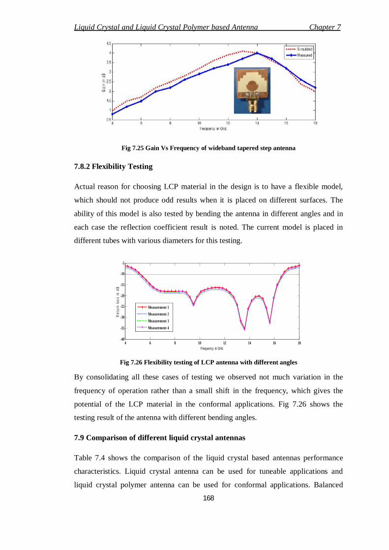
Fig 7.22 shows the antenna three dimensional radiation view at 13.6 GHz. Radiation
pattern of omni directional in E-plane and quasi omni directional in H-plane with low
cross polarization levels can be observed from Fig 7.23.
Liquid Crystal and Liquid Crystal Polymer based Antenna Chapter 7
167
Fig 7.22 Three dimensional view of radiation for wideband tapered step antenna at 13.6 GHz
Fig 7.23 Radiation pattern in E and H-plane of wideband tapered step antenna at 13.6 GHz
Fig 7.24 Current distribution of wideband tapered step antenna at 13.6 GHz
Fig 7.24 shows the simulated current distribution of the antenna at 13.6 GHz. The
current intensity is maximum at radiating element and feed line towards x-direction
with equal magnitude but opposite in polarity. Fig 7.25 shows the frequency Vs gain
plot for the liquid crystal polymer antenna. From this result we can observe that gain
is increasing up to 14 GHz and after reaching to the peak gain of 4 dB, the gain is
decreased at higher frequency.
Liquid Crystal and Liquid Crystal Polymer based Antenna Chapter 7
168
Fig 7.25 Gain Vs Frequency of wideband tapered step antenna
7.8.2 Flexibility Testing
Actual reason for choosing LCP material in the design is to have a flexible model,
which should not produce odd results when it is placed on different surfaces. The
ability of this model is also tested by bending the antenna in different angles and in
each case the reflection coefficient result is noted. The current model is placed in
different tubes with various diameters for this testing.
4 6 8 10 12 14 16 18-40
-35
-30
-25
-20
-15
-10
-5
Frequency in GHz
Ret
urn
loss
in d
B
Measurement 1Measurement 2Measurement 3Measurement 4
Fig 7.26 Flexibility testing of LCP antenna with different angles
By consolidating all these cases of testing we observed not much variation in the
frequency of operation rather than a small shift in the frequency, which gives the
potential of the LCP material in the conformal applications. Fig 7.26 shows the
testing result of the antenna with different bending angles.
7.9 Comparison of different liquid crystal antennas
Table 7.4 shows the comparison of the liquid crystal based antennas performance
characteristics. Liquid crystal antenna can be used for tuneable applications and
liquid crystal polymer antenna can be used for conformal applications. Balanced
Liquid Crystal and Liquid Crystal Polymer based Antenna Chapter 7
169
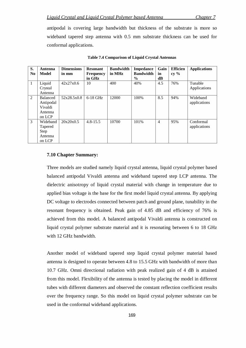
antipodal is covering large bandwidth but thickness of the substrate is more so
wideband tapered step antenna with 0.5 mm substrate thickness can be used for
conformal applications.
Table 7.4 Comparison of Liquid Crystal Antennas
S. No
Antenna Model
Dimensions in mm
Resonant Frequency in GHz
Bandwidth in MHz
Impedance Bandwidth %
Gain in dB
Efficiency %
Applications
1 Liquid Crystal Antenna
42x27x0.6 10 400 40% 4.5 76% Tunable Applications
2 Balanced Antipodal Vivaldi Antenna on LCP
52x28.5x0.8 6-18 GHz 12000 100% 8.5 94% Wideband applications
3 Wideband Tapered Step Antenna on LCP
20x20x0.5 4.8-15.5 10700 101% 4 95% Conformal applications
7.10 Chapter Summary:
Three models are studied namely liquid crystal antenna, liquid crystal polymer based
balanced antipodal Vivaldi antenna and wideband tapered step LCP antenna. The
dielectric anisotropy of liquid crystal material with change in temperature due to
applied bias voltage is the base for the first model liquid crystal antenna. By applying
DC voltage to electrodes connected between patch and ground plane, tunability in the
resonant frequency is obtained. Peak gain of 4.85 dB and efficiency of 76% is
achieved from this model. A balanced antipodal Vivaldi antenna is constructed on
liquid crystal polymer substrate material and it is resonating between 6 to 18 GHz
with 12 GHz bandwidth.
Another model of wideband tapered step liquid crystal polymer material based
antenna is designed to operate between 4.8 to 15.5 GHz with bandwidth of more than
10.7 GHz. Omni directional radiation with peak realized gain of 4 dB is attained
from this model. Flexibility of the antenna is tested by placing the model in different
tubes with different diameters and observed the constant reflection coefficient results
over the frequency range. So this model on liquid crystal polymer substrate can be
used in the conformal wideband applications.