Embed Size (px)
Citation preview
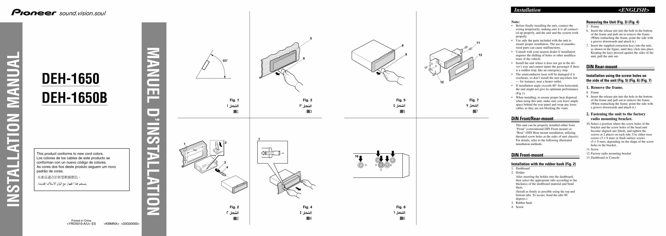
60°
7
<KMMNX> <03G00000>
DEH-1650DEH-1650B
Printed in China <YRD5010-A/U> ES
This product conforms to new cord colors.Los colores de los cables de este producto se conforman con un nuevo código de colores.As cores dos fios deste produto seguem um novopadrão de cores.
u�« l� “UN'« «c¼ r−�M¹Æ…b¹b'« „öÝô« Ê«
5
6
Fig. 4
¥ qJA�«
10
11
13
12
8
9
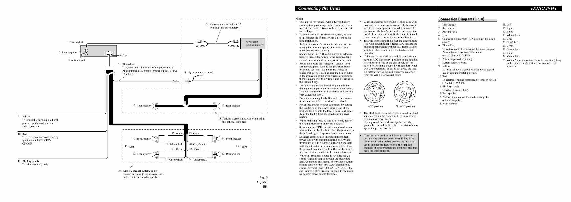
Note:• Before finally installing the unit, connect the
wiring temporarily, making sure it is all connect-ed up properly, and the unit and the system workproperly.
• Use only the parts included with the unit toensure proper installation. The use of unautho-rized parts can cause malfunctions.
• Consult with your nearest dealer if installationrequires the drilling of holes or other modifica-tions of the vehicle.
• Install the unit where it does not get in the dri-ver’s way and cannot injure the passenger if thereis a sudden stop, like an emergency stop.
• The semiconductor laser will be damaged if itoverheats, so don’t install the unit anywhere hot— for instance, near a heater outlet.
• If installation angle exceeds 60° from horizontal,the unit might not give its optimum performance.(Fig 1)
• When installing, to ensure proper heat dispersalwhen using this unit, make sure you leave amplespace behind the rear panel and wrap any loosecables so they are not blocking the vents.
DIN Front/Rear-mountThis unit can be properly installed either from“Front” (conventional DIN Front-mount) or“Rear” (DIN Rear-mount installation, utilizingthreaded screw holes at the sides of unit chassis).For details, refer to the following illustratedinstallation methods.
DIN Front-mount
Installation with the rubber bush (Fig. 2)1. Dashboard2. Holder
After inserting the holder into the dashboard,then select the appropriate tabs according to thethickness of the dashboard material and bendthem.(Install as firmly as possible using the top andbottom tabs. To secure, bend the tabs 90degrees.)
3. Rubber bush4. Screw
Removing the Unit (Fig. 3) (Fig. 4)5. Frame6. Insert the release pin into the hole in the bottom
of the frame and pull out to remove the frame.(When reattaching the frame, point the side witha groove downwards and attach it.)
7. Insert the supplied extraction keys into the unit,as shown in the figure, until they click into place.Keeping the keys pressed against the sides of theunit, pull the unit out.
DIN Rear-mount
Installation using the screw holes on the side of the unit (Fig. 5) (Fig. 6) (Fig. 7)
1. Remove the frame.8. Frame9. Insert the release pin into the hole in the bottom
of the frame and pull out to remove the frame.(When reattaching the frame, point the side witha groove downwards and attach it.)
2. Fastening the unit to the factoryradio mounting bracket.
10. Select a position where the screw holes of thebracket and the screw holes of the head unitbecome aligned (are fitted), and tighten thescrews at 2 places on each side. Use either trussscrews (5 × 8 mm) or flush surface screws (5 × 9 mm), depending on the shape of the screwholes in the bracket.
11. Screw12. Factory radio mounting bracket13. Dashboard or Console
Installation <ENGLISH>
Fig. 1
± qJA�«
Fig. 3
≥ qJA�«
Fig. 5
µ qJA�«
Fig. 6
∂ qJA�«
Fig. 7
∑ qJA�«
182
53
1 2
3
4
Fig. 2
≤ qJA�«
INST
ALLA
TION
MAN
UAL
MANUEL D’INSTALLATION
Nota:• Antes de finalmente instalar la unidad, conecte el
cableado temporalmente y asegúrese de que todoesté conectado correctamente y que la unidad yel sistema funcionan debidamente.
• Utilice sólo las piezas que se incluyen con estaunidad para asegurar la instalación adecuada. Eluso de piezas no autorizadas podría causar fallosde funcionamiento.
• Consulte con su distribuidor si la instalaciónrequiere del taladro de orificios u otras modifica-ciones del vehículo.
• Instale la unidad donde no alcance el espacio delconductor, y donde no pueda dañar a lospasajeros si sucediera un paro repentino, comouna detención de emergencia.
• El semiconductor láser se dañará si se sobre-calienta, por eso no instale la unidad en un lugarcaliente – por ejemplo, cerca de la salida de uncalefactor.
• Si el ángulo de la instalación excede los 60° dellado horizontal, la unidad podría no brindar suóptimo funcionamiento (Fig 1).
• Cuando instale, para asegurar la dispersiónapropiada del calor cuando utilice la unidad,asegúrese de dejar un amplio espacio detrás delpanel trasero y de enrollar cualesquiera cablessueltos de modo que no bloqueen las aberturas deventilación.
Montaje delantero/trasero DINEsta unidad quede instalarse correstamente de la“Delantera” (montaje delantero DIN conven-ciona) o “Trasera” (montaje trasero DIN, uti-lizando los tornillos roscados en los constadosdel chasis de la unidad). Para detalles, refiérase alos métodos de instalación ilustrados abajo.
Montaje delantero DIN
Instalación con tope de goma (Fig. 2)1. Tablero de instrumentos2. Soporte
Después de insertar el soporte en la tabla demandos, luego seleccione las orejetas apropiadassegún el grosor del material de la tabla de man-dos y dóblelos.(Instale lo más firme posible usando las lengüetassuperior e inferior. Para fijar, doble las lengüetas90 grados.)
3. Tope de goma4. Tornillo
Quitado de la unidad (Fig. 3) (Fig. 4)5. Marco6. Inserte el pasador de liberanción en el orificio de
la parte inferior del marco, y tire hacia afuerapara extraer el marco.(Para la fijación del marco, apunte el lado conranura hacia abajo.)
7. Inserte las herramientas de extracción sumin-istradas en la unidad, como se indica en la figura,hasta que se enganchen en su positión.Tire de la unidad mientras mantiene las her-ramientas presionadas contra los lados de launidad.
Montaje trasero DIN
Instalación usando los agujeros paratornillos ubicados en ambos costados de la unidad (Fig. 5) (Fig. 6) (Fig. 7)
1. Quite el marco.8. Marco9. Inserte el pasador de liberanción en el orificio de
la parte inferior del marco, y tire hacia afuerapara extaer el marco.(Para la fijación del marco, apunte el lado conranura hacia abajo.)
2. Fijación de la unidad a la ménsula demontaje existente.
10. Seleccione una posición en la que los orificiospara los tornillos del soporte y del de la unidadprincipal queden alineados, y apriete los tornillosen 2 lugares de un lado. Utilice ya sea los tornil-los de fijación (5 × 8 mm) o los tornillos a paño(5 × 9 mm), dependiendo de la forma de los ori-ficios de tornillo en la ménsula.
11. Tornillo12. Ménsula de montaje de radio existente13. Tablero de instrumentos o consola
Instalación <ESPAÑOL>
Nota:• Antes de instalar o aparelho, conecte os fios tem-
porariamente, certificando-se de que todos este-jam conectados corretamente, e que o aparelho eo sistema completo funcionem adequadamente.
• Utilize somente as peças incluídas com o aparel-ho para garantir uma instalação correta. O uso depeças não autorizadas pode causar defeitos.
• Consulte o seu revendedor mais próximo se fornecessário fazer perfurações ou outras modifi-cações no veículo para a instalação.
• Instale o aparelho de modo que não fique nocaminho do motorista nem onde possa causardanos aos passageiros no caso de uma paradarepentina, como numa freada de emergência.
• O laser de semicondutor será avariado se forsobreaquecido. Portanto, não instale o aparelhonum lugar que fique muito quente como porexemplo, perto da saída do aquecedor.
• Se o ângulo de instalação exceder de 60° desde ahorizontal, o aparelho pode não atingir sua per-formance ótima (Fig 1).
• Quando instalar, para assegurar a dispersão apro-priada do calor ao utilizar o aparelho, certifique-se de deixar um amplo espaço atrás do painel tra-seiro e de enrolar quaisquer cabos soltos demodo que não bloqueiem as aberturas de venti-lação.
Montagem dianteira/traseira DINEste aparelho pode ser instalado apropriadamentena “Dianteira” (montagem convencional dianteiraDIN) ou na “Traseira” (montagem traseira DIN,utilizando os orifícios de parafusos roscados noslados do chassi do aparelho). Para maiores detal-hes, refira-se aos seguintes métodos de instalaçãoilustrados.
Montagem dianteira DIN
Instalação com uma bucha de borracha(Fig. 2)1. Painel de instrumentos2. Sujeitador
Depois de inserir o sujeitador no painel de instru-mentos, escolha as lingüetas apropriadas de acor-do com a espessura do material do painel deinstrumento, e dobre-as.(Instale o mais firme possível usando as lingüetassuperior e inferior. Para fixar, dobre as lingüetas90 graus.)
3. Bucha de borracha4. Parafuso
Remoção do aparelho (Fig. 3) (Fig. 4)5. Armação6. Insira o pino de liberação no orifício no fundo da
armação e puxe-o para fora para remover aarmação.(Quando recolocar a armação, aponte o lado coma ranhura para baixo e fixe-a.)
7. Insira as chaves de extração fornecidas no aparel-ho, como mostrado na figura, até que elas seencaixem em posição. Enquanto mantém aschaves pressionadas contra os lados do aparelho,puxe o aparelho para fora.
Montagem traseira DIN
Instalação utilizando os orifícios de parafuso no lado do aparelho (Fig. 5) (Fig. 6) (Fig. 7)
1. Retire a armação.8. Armação9. Insira o pino de liberação no orifício no fundo da
armação e puxe-o para fora para remover aarmação.(Quando recolocar a armação, aponte o lado coma ranhura para baixo e fixe-a.)
2. Fixação do aparelho no suporte demontagem de rádio da fábrica.
10. Escolha a posição onde os orifícios de parafusosdo suporte e os orifícios dos parafusos do com-ponente principal fiquem alinhados (ajustados), eaperte os parafusos em 2 lugares em cada lado.Utilize parafusos reforçados (5 × 8 mm), ou para-fusos embutidos (5 × 9 mm), dependendo daforma dos orifícios para os parafusos no suporte.
11. Parafuso12. Suporte de montagem de rádio da fábrica13. Painel de instrumentos ou consolo
Instalação <PORTUGUÊS (B)> VO�d²�«ææWOÐdF�«º
ÂUEM�«DINw�U�_« XO³¦²K�
UD*« W½UD³�« l� VO�d²�«©≤ qJA�«® WOÞ
1≠u�eNł√ WŠ”UOI�« …
2≠WJÝU*«
u� w� WJÝU*« ‰Ušœ≈ bFÐeNł√ WŠ…
ËdF�« d²š≈ rŁÆ”UOI�«V$Š W³ÝUM*« «
u� …œU( W)ULÝeNł√ WŠÆUNMŁ≈ Ë ”UOI�« …
d²�UÐ r+®‰ULF²ÝUÐ ÊUJ(ô« —bIÐ ÂUJŠUÐ VO)
ËdF�«uKF�« «Ë W¹wM¦Ð r+ ¨5(P²K� ÆWOKH$�«
ËdF�«—œ π∞ «©ÆWł
3≠WOÞUD( W½UDÐ
4≠dÐwž
©¥ qJA�«® ©≥ qJA�«® “UN'« Ÿe½
5≠—UÞ≈
6≠u*« VI¦�« w� ‚U²Žù« —UL$( qšœ√ułw� œ
Ë —UÞû� wKH$�« V½U'«ŸdM� ×UGK� »cł«
Ë Æ—UÞù« qOJuð …œUŽ≈ bMŽ® Æ—UÞù«V½U'« tł
©ÆtKOJu²Ð r+ Ë qHÝ_ oA�UÐ
7≠dG²Ýô« `OðUH( qšœ√d*« ëu�« w� WI�¨…bŠ
u*U)d¹ v²Š ¨qJA�« w� `{uGÝrN½UJ( w� «
uJ —ËbBÐ ÂUJŠUÐjGCÐ ÿUH²Šô« l( WIÞ
u�« w³½Uł qÐUI( `OðUH*«u�« V×Ý≈ ¨…bŠ…bŠ
Æ×UGK�
ÂUEM�«DINwHK)« XO³¦²K�
vKŽ …œułu*« wž«d³�« »uIŁ ‰ULF²ÝUÐ VO�d²�«
©∑ qJA�«® ©∂ qJA�«® ©µ qJA�«® …bŠu�« w³½Uł
≠±≠±≠±≠±≠±—UÞù« Ÿe½≈—UÞù« Ÿe½≈—UÞù« Ÿe½≈—UÞù« Ÿe½≈—UÞù« Ÿe½≈
8≠—UÞô«
9≠√œšq ($LU— «_Ž²U‚ �w «�¦IV «*ułuœ �w «'U½V
«�$HKw �öÞU— Ë«łc» �KGU—à �MeŸ «ôÞU—Æ
Ë ¨—UÞô« qOJuð …œUŽ≈ bMŽ®łÓoA�UÐ V½U'« t
©ÆtKOJu²Ð r+ Ë qHÝ_
≠≤≠≤≠≤≠≤≠≤ËËËËËÓÓ ÓÓ ÓŁŁŁŁŁÚÚ ÚÚ ÚlMB*« WHO²) v�≈ …bŠu�« olMB*« WHO²) v�≈ …bŠu�« olMB*« WHO²) v�≈ …bŠu�« olMB*« WHO²) v�≈ …bŠu�« olMB*« WHO²) v�≈ …bŠu�« o
Æu¹œ«d�« XO³¦²� WOKJ_«Æu¹œ«d�« XO³¦²� WOKJ_«Æu¹œ«d�« XO³¦²� WOKJ_«Æu¹œ«d�« XO³¦²� WOKJ_«Æu¹œ«d�« XO³¦²� WOKJ_«
10≠≈š²d (u{FÎU ðÔB³ ̀�Ot ŁIu» Ðd«žw «�J²OHW Ë
ŁIu» Ðd«žw «�uŠb… «�dzO$OW (²d«JHW ®ðB³`
(²DUÐIW©¨ Ë«ŠJr —Ðj «�³d«žw ŽMb «*u{F5 ŽKv
)q łU½VÆ ≈ݲGb ≈(U Ðd«žw ðIOOb ®µ ™ ∏ 3© √Ë
Ðd«žw (K$U¡ «�$D` ®µ™π 3©¨ Ë ¹F²Lb –�p ŽKv
ýJq ŁIu» «�³d«žw «*ułuœ… �w «�J²OHW Æ
11≠dÐwž
12≠d�« XO³¦²� ZOKJ_« lMB*« WHO²)u¹œ«
13≠u�eNł√ WŠe)« Ë√ ”UOI�« …W½«
∫WEŠö�∫WEŠö�∫WEŠö�∫WEŠö�∫WEŠö�
•dð q³+OzUN½ “UN'« VO)ÎpKÝô« qOJu²Ð r+ ¨U
R( qJAÐq) qOJuð W×J s( b)Q²�« l( ¨X+
Ë „öÝô«ÆÂUEM�« Ë “UN'« qOGAð W(öÝ
•u*« lDI�« qLF²Ý≈ułb)U²K� jI� “UN'« l( …œ
d²�« s(dOž lD+ ‰ULF²Ý≈ VÝUM*« VO)
d(ÆôUDŽ√ V³$¹ Ê√ sJ1 WBš
•d+√ dA²Ý«Ë »d²�« VKDð «–≈ p� qO)qLŽ VO)
uIŁdš√ ö¹bFð Ë√ »dO$�« w� ÈÆ…
•—d²F¹ ô YOŠ “UN'« V)dŠ ÷ô Ë ozU$�« W)
u¹ Ê√ sJ1d�« Í–u+ Ë W�UŠ w� »U)·
u�« q¦(Æ¡vłUH(u+uD�« bMŽ ·—«Æ¡È
•dFð «–« —eOK�« qJu( t³ý qDF²OÝ—ô ÷ŸUHð
—œdŠ Wł—«dð ô «c� ¨tðÊUJ( Í√ w� “UN'« V)
dI�UÐ ¨ö¦( fl sšUÝÃdš Uײ� s( »
ÆW¾�b²�«
•“ËU& «–≈“ Ë«d²�« W¹ô bI� o�_« s( ∂∞ VO)
R¹©± qJA�«® Æq¦(_« tKLŽ “UN'« Íœ
•d²�« bMŽË s( b)Qð ¨VO)ułdŠ XO²A𠜗«Í
Ë ¨“UN'« «c¼ «bG²Ý« bMŽ VÝUM(dð s( b)Qð„
d�uK�« nKš w�U) ⁄«Ë WO(U(ô« WŠ ö³J�« n�
d*«uN²�« Uײ� b$ð ô v²Š WOšÆW¹
ÂUEM�«DINwHK)«Øw�U�_« XO³¦²K�
dð sJ1u�« Ác¼ VO)s( U(≈ VÝUM( qJAÐ …bŠ
ÂUEM�«® ¢ÂU(_«¢DINXO³¦²K� ÈbOKI²�«
ÂUEM�«® ¢nK)«¢ Ë√ ©w(U(_«DINd²� VO)
uI¦Ð …œUH²ÝùUÐ ¨wHK)« XO³¦²�«d³�« »wž«
$*«Òu*« XMMułuł vKŽ …œu�« qJO¼ V½«Æ©…bŠ
—≈ ¨qOJUH²K�d²�« ‚dÞ v�« lłu*« VO)W×{
ÆwK¹ ULO�
+
≠
+
≠
+
≠
+
≠
+
≠
+
≠
V23. iolet
12.
25. With a 2 speaker system, do notconnect anything to the speaker leadsthat are not connected to speakers.
r12. Rea speaker
16. Right
Rear speaker
24. Violet/black
20. Gray/black
14. Front speaker
19. Gray17. White
18. White/black
21. Green
22. Green/black
15. Left
14. Front speaker
12. Rear speaker 12. Rear speaker
13.
8. System remote control
5. Connecting cords with RCApin plugs (sold separately)
7. Power amp(sold separately)
4. Fuse
6. Blue/whiteTo system control terminal of the power amp orAuto-antenna relay control terminal (max. 300 mA12 V DC).
1. This Product
2. Rear output
3. Antenna jack
9. YellowTo terminal always supplied withpower regardless of ignitionswitch position.
10. RedTo electric terminal controlled byignition switch (12 V DC)ON/OFF.
11. Black (ground)To vehicle (metal) body.
Perform these connections when usingthe optional amplifier.
Note:• This unit is for vehicles with a 12-volt battery
and negative grounding. Before installing it in arecreational vehicle, truck, or bus, check the bat-tery voltage.
• To avoid shorts in the electrical system, be sureto disconnect the ≠ battery cable before begin-ning installation.
• Refer to the owner’s manual for details on con-necting the power amp and other units, thenmake connections correctly.
• Secure the wiring with cable clamps or adhesivetape. To protect the wiring, wrap adhesive tapearound them where they lie against metal parts.
• Route and secure all wiring so it cannot touchany moving parts, such as the gear shift, hand-brake and seat rails. Do not route wiring inplaces that get hot, such as near the heater outlet.If the insulation of the wiring melts or gets torn,there is a danger of the wiring short-circuiting tothe vehicle body.
• Don’t pass the yellow lead through a hole intothe engine compartment to connect to the battery.This will damage the lead insulation and cause avery dangerous short.
• Do not shorten any leads. If you do, the protec-tion circuit may fail to work when it should.
• Never feed power to other equipment by cuttingthe insulation of the power supply lead of theunit and tapping into the lead. The current capac-ity of the lead will be exceeded, causing over-heating.
• When replacing fuse, be sure to use only fuse ofthe rating prescribed on the fuse holder.
• Since a unique BPTL circuit is employed, neverwire so the speaker leads are directly grounded orthe left and right ≠ speaker leads are common.
• Speakers connected to this unit must be high-power types with minimum rating of 50W andimpedance of 4 to 8 ohms. Connecting speakerswith output and/or impedance values other thanthose noted here may result in the speakers catch-ing fire, emitting smoke, or becoming damaged.
• When this product’s source is switched ON, acontrol signal is output through the blue/whitelead. Connect to an external power amp’s systemremote control or the car’s Auto-antenna relaycontrol terminal (max. 300 mA 12 V DC). If thecar features a glass antenna, connect to the anten-na booster power supply terminal.
• When an external power amp is being used withthis system, be sure not to connect the blue/whitelead to the amp’s power terminal. Likewise, donot connect the blue/white lead to the power ter-minal of the auto-antenna. Such connection couldcause excessive current drain and malfunction.
• To avoid short-circuiting, cover the disconnectedlead with insulating tape. Especially, insulate theunused speaker leads without fail. There is a pos-sibility of short-circuiting if the leads are notinsulated.
• If this unit is installed in a vehicle that does nothave an ACC (accessory) position on the ignitionswitch, the red lead of the unit should be con-nected to a terminal coupled with ignition switchON/OFF operations. If this is not done, the vehi-cle battery may be drained when you are awayfrom the vehicle for several hours.
• The black lead is ground. Please ground this leadseparately from the ground of high-current prod-ucts such as power amps.If you ground the products together and theground becomes detached, there is a risk of dam-age to the products or fire.
• Cords for this product and those for other prod-ucts may be different colors even if they havethe same function. When connecting this prod-uct to another product, refer to the suppliedmanuals of both products and connect cords thathave the same function.
Connecting the Units
ACC position
ACCON
STA
R
T
OFF
ONS
TA
R
T
OFF
No ACC position
<ENGLISH>
Connection Diagram (Fig. 8)1. This Product2. Rear output3. Antenna jack4. Fuse5. Connecting cords with RCA pin plugs (sold sep-
arately)6. Blue/white
To system control terminal of the power amp orAuto-antenna relay control terminal (max. 300 mA 12 V DC).
7. Power amp (sold separately)8. System remote control9. Yellow
To terminal always supplied with power regard-less of ignition switch position.
10. RedTo electric terminal controlled by ignition switch(12 V DC) ON/OFF.
11. Black (ground)To vehicle (metal) body.
12. Rear speaker13. Perform these connections when using the
optional amplifier.14. Front speaker
15. Left16. Right17. White18. White/black19. Gray20. Gray/black21. Green22. Green/black23. Violet24. Violet/black25. With a 2 speaker system, do not connect anything
to the speaker leads that are not connected tospeakers.
Fig. 8
∏ qJA�«
Nota:• Esta unidad es para vehículos con batería de 12
voltios y con conexión a tierra. Antes de instalarla unidad en un vehículo recreativo, camioneta, oautobús, revise el voltaje de la batería.
• Para evitar cortocircuitos en el sistema eléctrico,asegúrese de desconectar el cable de la batería ≠antes de comenzar con la instalación.
• Consulte con el manual del usuario para los detallessobre la conexión de la alimentación de amperios y deotras unidades, luego haga las conexiones correctamente.
• Asegure el cableado con abrazaderas de cables ocon cinta adhesiva. Para proteger el cableado,envuélvalo con cinta adhesiva donde éstos seapoyan sobre las piezas de metal.
• Coloque y asegure todo el cableado de tal manera queno toque las piezas en movimiento, tal como la palan-ca de cambio de velocidades, el freno de mano, y lospasamanos de los asientos. No coloque el cableado enlugares que se calientan, tal como cerca de la salidade un calefactor. Si el material aislante del cableadose derritiera o se gastara, habrá el peligro de un corto-circuito del cableado a la carrocería del vehículo.
• No pase el conductor amarillo a través de un orifi-cio en el compartimiento del motor para conectara la batería. Esto dañará el material aislante delconductor y causará un cortocircuito peligroso.
• No acorte ningún conductor. Si lo hiciera, la proteccióndel circuito podría fallar al funcionar cuando debería.
• Nunca alimente energía a otros equipos cortandoel aislamiento del conductor de alimentación pro-vista de la unidad y haciendo un empalme con elconductor. La capacidad de corriente del conduc-tor se excederá, causando el recalentamiento.
• Cuando reemplace algún fusible, asegúrese deutilizar solamente un fusible del ratio descrito enel soporte de fusibles.
• Ya que se emplea un circuito único BPTL, nuncacoloque los cables de manera que los conductores delaltavoz estén directamente en conexión a tierra o queel altavoz izquierdo y derecho ≠ sean comunes.
• Los altavoces conectados a esta unidad deberán ser deltipo de alta potencia, teniendo un régimen mínimo de50W y una impedancia de 4 a 8 ohmios. La conexiónde altavoces con valores de impedancia y/o de salidadiferentes a los anotados aquí podrían causar fuego,emisión de humo o daños a los altavoces.
• Cuando se conecta la fuente de este producto,una señal de control se emite a través del conduc-tor azul/blanco. Conecte al control remoto de sis-tema de un amplificador de potencia externo o alterminal de controle de relé de antena automáticadel vehículo. (Max. 300 mA 12 V CC.) Si elvehículo tiene una antena en vidrio, conecte alterminal de suministro de energía de la antena.
• Cuando se está utilizando un amperio de potenciaexterna con este sistema, asegúrese de no conec-tar el conductor azul/blanco al terminal de poten-cia de amperios. Asimismo, no conecte el con-ductor azul/blanco al terminal de potencia de laauto-antena. Tal conexión podría causar la fugade corriente excesiva y causar fallos de fun-cionamiento.
• Para evitar cortocircuitos, cubra el conductordesconectado con cinta aislada. Especialmente,aísle los conductores de altavoz no usados. Hayla posibilidad de cortocircuito si no se aíslan losconductores.
• Si se instala esta unidad en un vehículo que notiene una posición ACC (accesorio) en el inter-ruptor de encendido, el conductor rojo de launidad deberá conectarse al terminal conectadocon las operaciones del interruptor de encendidoON/OFF. Si no se hace esto, la batería delvehículo podría drenarse cuando usted esté lejosdel vehículo por varias horas.
• El conductor negro es la masa. Conecte a masaeste conductor separadamente desde la masa delos productos de alta corriente tal como losamplificadores de potencia. Si conecta juntos a masa los productos y la masase desconecta, se crea el riesgo de daños a losproductos o de incendios.
• Los cables para esta unidad y aquéllas para lasunidades pueden ser de colores diferentes aun sitienen la misma función. Cuando se conecta estaunidad a otra, refiérase a los manuales de ambasunidades y conecte los cables que tienen lamisma función.
Conexión de las unidades
Posición ACC
ACCON
STA
R
T
OFF
ONS
TA
R
T
OFF
No en la posición ACC
<ESPAÑOL>
Diagrama de conexión (Fig. 8)1. Este producto2. Salida trasera3. Jack para antena4. Fusible5. Cables de conexión con clavijás RCA (en venta
por separado).6. Azul/blanco
Al terminal de control de sistema del amp. depotencia o control de relé de antena automática(máx. 300 mA 12 V de CC).
7. Amplificador de potencia (en venta por separado)8. Control remoto de sistema9. Amarillo
Al terminal con suministro constante de electrici-dad, independientemente de la posición de inter-ruptor de encendido.
10. RojoAl terminal de energía eléctrica controlado por elinterruptor de encendido del vehículo (12 VC.C.) ON/OFF.
11. Negro (masa)A la carrocería del veículo (parte metálica).
12. Altavoz trasero13. Lleve a cabo estas conexiones cuando utilice el
amplificador opcional.14. Altavoz delantero
15. Izquierda16. Derecha17. Blanco18. Blanco/negro19. Gris20. Gris/negro21. Verde22. Verde/negro23. Violeta24. Violeta/negro25. Con un sistema de 2 altavoces, no conecte nada a
los hilos de altavoz que no se conectam a losaltavoces.
Nota:• Este aparelho foi concebido para veículos com uma
bateria de 12 Volts e conexão à terra negativa. Antesde instalar o aparelho num veículo recreativo, cam-inhão ou ônibus, verifique a voltagem da bateria.
• Para evitar curto-circuitos no sistema elétrico,certifique-se de desconectar o cabo ≠ da bateriaantes de iniciar a instalação.
• Consulte o manual do proprietário para maiores detal-hes sobre como conectar um amplificador de potênciae as outras unidades, e faça as conexões corretamente.
• Prenda os fios com braçadeiras de cabo ou fita adesi-va. Para proteger os fios, enrole fita adesiva em voltadeles onde eles fiquem contra partes metálicas.
• Encaminhe e segure todos os fios de modo quenão toquem em partes móveis, tais como a alavan-ca de mudanças de marcha, alavanca do freio deestacionamento e trilhos dos assentos. Não encam-inhe os fios em lugares que ficam muito quentes,tais como perto da saída do aquecedor. Se o isola-mento dos fios derreter-se ou cortar-se, há o peri-go de curto-circuito com a carroçaria do veículo.
• Não passe o fio amarelo através do orifício nocompartimento do motor para conectá-lo à bate-ria. Isso danificará o isolamento do fio e causaráum curto-circuito muito perigoso.
• Não deixe os fios entrarem em curto-circuito. Se issoocorrer, o circuito de proteção poderá não funcionar.
• Nunca forneça energia a outros equipamentos cortan-do o isolamento do fio de alimentação do componentee fazendo uma emenda. A capacidade de corrente dofio será excedida, causando um sobreaquecimento.
• Ao substituir o fusível, certifique-se de utilizarsomente um fusível com a potência nominal pre-scrita no porta-fusíveis.
• Como se emprega um único circuito BPTL,nunca faça a instalação elétrica de modo que osfios dos alto-falantes fiquem diretamente conec-tados à terra nem que os fios esquerdo e direito≠ dos alto-falantes fiquem em comum.
• Os alto-falantes conectados a este componente devemser do tipo de alta potência, com uma potência nomi-nal mínima de 50W e uma impedância de 4 a 8 ohms.Conectar alto-falantes com valores de saída e/ouimpedância diferentes dos especificados pode causar ofogo, emissão de fumaça ou danos aos alto-falantes.
• Quando se conecta a fonte deste produto, um sinalde controle é emitido através do condutor azul/bran-co. Conecte ao controle remoto de sistema de umamplificador de potência externo ou ao terminal decontrole de relé de antena automática do veículo.(Máx. 300 mA, 12 V CC.) Se o veículo tem umaantena incorporada em vidro, conecte ao terminalde fornecimento de energia da antena.
• Ao utilizar um amplificador de potência externocom este sistema, certifique-se de não conectar ofio azul/branco do terminal de potência do ampli-ficador. Do mesmo modo, não conecte o fioazul/branco do terminal de potência da antenaautomática. Tal conexão poderia causar umadrenagem de corrente excessiva e um conse-qüente mau funcionamento.
• Para evitar curto-circuitos, cubra o condutordesconectado com fita isolante. Especialmente,isole os condutores de alto-falante não usados.Há a possibilidade de curto-circuito se os condu-tores não forem isolados.
• Se este componente for instalado num veículonão equipado com uma posição ACC (acessório)na chave de ignição, o fio vermelho do compo-nente deve ser conectado ao terminal acopladocom as operações de ligar/desligar da chave deignição. Se isso não for feito, a bateria do veículopode descarregar-se quando você ficar fora doveículo durante várias horas.
• O cabo preto é para a terra. Aterre este cabo sep-aradamente da terra de produtos de corrente altacomo amplificadores de potência.Se você ligar aterrar os produtos juntos e a terrafor desligada, haverá o risco de danos aos produ-tos ou incêndio.
• Os cabos para este aparelho e os de outros com-ponentes podem ter cores diferentes, mesmo quetenham a mesma função. Quando conectar esteaparelho a um outro aparelho, consulte os manu-ais de ambos os aparelhos e conecte os cabos quetenham a mesma função.
Conexão das unidades
Posição ACC
ACCON
STA
R
T
OFF
ONS
TA
R
T
OFF
Sem posição ACC
Diagrama de Conexão (Fig. 8)1. Este componente2. Saída traseira3. Jaque para antena4. Fusível5. Conexão dos cabos com plugues de pino RCA
(vendido separadamente).6. Azul/branco
Ao terminal de controle do sistema do amplifi-cador de potência ou terminal de controle de reléda antena automática (máx. 300 mA, 12 V CC).
7. Amplificador de potência (vendido separada-mente)
8. Controle remoto de sistema9. Amarelo
Ao terminal sempre fornecido com energia inde-pendentemente da posição da chave de ignição.
10. VermelhoAo terminal controlado pelo ligar/desligar dachave de ignição (12 V CC).
11. Preto (terra)À carroçaria (metal) do veículo.
12. Alto-falante traseiro13. Realize estas conexões quando utilizar o amplifi-
cador opcional.14. Alto-falante dianteiro
15. Esquerda16. Direita17. Branco18. Branco/preto19. Cinza20. Cinza/preto21. Verde22. Verde/preto23. Violeta24. Violeta/preto25. Com um sistema de 2 alto-falantes, não conecte
nada aos fios de alto-falante que não estão conec-tados a alto-falantes.
<PORTUGUÊS (B)>
•—b+ rGC( qOJuð bMŽs( b)Q𠨓UN'« «cNÐ …
dÞ v�« iOÐô«Ø‚—“ô« pK$�« qOJuð ÂbŽ·
—bI�« rGC( qOJuðË Æ…ÂbŽ V−¹ ¨p�c)
dÞ v�« iOÐô«Ø‚—“ô« pK$�« qOJuð—b+ ·…
uN�««c¼ q¦( V³$²¹ b+ YOŠ Æw�ü« wz«
dBð v�« qOJu²�«dNJ�« —UO²K� b¹bý n¹ÆwzUÐ
•ËbŠ VM−²�dz«bK� dB+ ÀdNJ�« …r+ ¨WOzUÐ
uÐ ‰uBH*« pK$�« WODG²Ðdý WDݫƉ“UŽ j¹
Ë—uBЄöÝ« ‰eF� p�UL¼« ÂbŽ V−¹ ¨WJUš …
„UM¼ Ê« YOŠ ÆW(bG²$*« dOž WŽUL$�«
Ë WO½UJ(«dz«bK� dOBIð Ÿu+dNJ�« …r� «–« WOzUÐ
Æ„öÝô« ‰eŽ r²¹
•—UOÝ w� “UN'« «c¼ qOJuð - «–≈fO� wM�« Ë …
Ë UNÐ ‰UFýù« ÕU²H0 © UI×K*«® l{ACC¨
dDÐ “UNłô dLŠ_« pK$�« qOJuð V−O�·
e( qOGA²�« UOKLŽ l( ÃËœON qHI�«Ø OFFcHMð bI� ¨ p�– r²¹ r� Ê≈ ¨‰UFýù« ÕU³H*
—UDЗUO$�« W¹bOFÐ ÊuJð U(bMŽ …Î
—UO$�« sŽ «…
Æ UŽUÝ …bF�
•uÝô« pK$�«—ô« pKÝ u¼ œd¹ Æw{qOJuð vł
—ô« «c¼—uBÐ w{qOJuð sŽ WKBHM( …
dNJ�« —UO²�« «– U−²M*«…bA�« w�UF�« wzUÐ
—bI�« ULGC( q¦(Æ…
—« XKJË «–«Ë UF( U−²M*« q) w{pKÝ qBH½«
—ô«‰UL²Š« „UM¼ ÊU� ¨»U³Ýô« s( V³$� ÷
uA½ Ë√ qDF�UÐ U−²M*« WÐUJ«dŠ »Æo¹
•u�« ÊuJð b+Ë “UN'« «c¼ „öÝ« Ê«WJU)« pKð
eNłôUÐdšô« …Ë v²Š WHK²G( ÈfH½ UN� ÊU) u�
eNł« v�« “UN'« «c¼ qOJuð bMŽ ÆqLF�«dš« …¨È
—«—ô« U³O²) v�« lł“UN'« öJ� «œUýrŁ s¹
u�« fH½ UN� w²�« „öÝô« qJËÆUF( WHOþ
∫WEŠö�∫WEŠö�∫WEŠö�∫WEŠö�∫WEŠö�
•—UO$K� hBG( “UN'« «c¼qLFð w²�« «
—UD³Ðu� ±≤ W¹—Qð Ë j�dð q³+ V�UÝ i¹t³O)
—UOÝ w�Ë√ WMŠUý Ë√ ÂUL−²Ýö� WBBG( …
—UD³�« bNł s( oI% ¨WK�UŠÆW¹
•Ëœ VM−²�dNJ�« ÂUEM�« w� dBI�« dz«b)Qð ¨wzUÐ
—UD³�« q³) qB� s( W¹≠d²�« ¡bÐ q³+ ÆVO)
•—≈dF* pK*« qO�œ v�≈ lłqJË ‰uŠ qOJUH²�« W�
—bI�« rGC(Ë …eNł_«dš_« …qLŽ« rŁ È
Æ`O×J qJAÐ öOJu²�«
•dý Ë√ ö³) pÐUA0 qOJu²�« „öÝ√ X³Łj¹
dA�« n� ¨ qOJu²�« „öÝ√ W¹UL( ¨oJôj¹
uŠ oJö�«eł_« l( UNÝU9 ÊUJ( w� UN�¡«
ÆWO½bF*«
•Ë —e(ô UN½√ YO×Ð qOJu²�« „öÝ√ q) X³Ł
eł√ W¹√ fLKð Ê√ sJ1dײ( ¡«—– q¦( ¨ W)Ÿ«
d$�« dOOGðdH�« Ë WŽËbO�« WK(Ë W¹e½« ÊU³C+‚ô
s)U(Qð w� qOJu²�« „öÝ√ —e9 ô ÆbFI*«
—UŠ `³Bðd+ q¦( ¨…«–« Æ¡v�b*« ÃdG( »
„UMN� ¨‚e9 Ë√ qOJu²�« „öÝ√ ‰“UŽ dNB½«
ËbŠ dBšdz«œ Àl( qOJu²�« „öÝ_ dB+ …
—UO$�« r$łÆ…
•d;« r$+ v�« VI¦�« d³Ž dHJô« pK$�« —d9 ô„
—UD³�UÐ tKOJu²�ÆW¹
Ë pK$�« ‰eŽ nK²OÝ «c¼dz«œ V³$¹dB+ …
dODš«bł …ÎÆ
•dz«œ V³$ð ô¨«c¼ XKF� «–« ÆpKÝ ÍQÐ dB+ …
dz«œ qAHð bI�ULMOŠ qLF�« w� W¹UL(« …
Æp�– wG³M¹
•bÐ√ rIð ôΗbI�« W¹cG²Ð «“UNł v�« …lD+ d³+ dš¬
Ëeð pKÝ ‰“UŽ—bI�« b¹pKÝ qJË Ë “UNłô …
d�—bI�« “ËU& r²O$� ÆwŽU2 ¨pK$K� WO�U(« …
¡ULŠ≈ V³$¹Î“«bz«ÎÆ«
•“uOH�« ‰«b³²Ý« bMŽ‰ULF²Ý« s( b)Pð ¨ «
d¹UF*« Ë– “uOH�«u*« …u�« Ác¼ vKŽ W×{Æ…bŠ
•dz«b�« «bG²Ý« - t½√ YOŠ …BPTLdH�« ô ¨ …b¹
uðÌJÒ—e�UÐ UŽUL$�« „öKÝ√ qdDÐ w¦{ZI¹
dýU³(eð qJuð Ë√ UIKB( …5²ŽUL$�« „öÝ
d$O�« Ë vMLO�« È≠ÆULNCFÐ l(
•Ác¼ v�≈ WKB²*« UŽUL$�« ÊuJð Ê√ wG³M¹
u�«—bI�« w�UF�« ŸuM�« s( …bŠbŠ Ë– ‰bF0 …
Ë µ∞ v½œ«Ë q+ô« vKŽ ◊«ËUF(Ë√ ∏ v�≈ ¥ W+Ê≈ ÆÂ
ËUF( Ë√ØË Ãdš rOIÐ UŽULÝ qOJuðdOž W+
—u)c*«Ë tMŽ Z²M¹ b+ UM¼ …dŠ Ÿu+Ë√ ¨o¹
Æ UŽUL$K� nKð Ë√ ¨ÊUšœ ÀUF³½«
• qOGAð bMŽON¨“UN'« «c¼ l( qJu²*« —bB*«
dš« r²OÝ—Uý« ë؂—“ô« pK$�« d³Ž rJ% …
Ë v�« qJË ÆiOÐô«ÂUEM� bFÐ sŽ rJ% …bŠ
uJ rGC(—Uš w�¬ dÞ Ë√ włw� rJײ�« ·
d(uN�« qŠËô« wz«uð≥∞∞ vB+ô« b(«® ÆwJOðU(
dL²$( —UOð dO³(« wKO(DCuIÐ u� ±≤ …©ÆX�
—UO$�« X½U) «–«eN−( …uNÐ …d( wz«vKŽ V)
dÞ v�« qJË ¨…c�UM�«Ëe²�« ·W+UD�UÐ b¹
dNJ�«uN�« “eF* WOzUÐÆwz«
u�« l{ACCu�« ÊËbÐ l{ACC
ACCON
ST
AR
T
OFF
ONS
TA
R
T
OFF
…eNł_« qODuðæWOÐdF�«º
©∏ qJA�«® qODu²�« jDG�
1≠“UN'« «c¼
2≠wHK)« Ãdš«
3≠uN�« f³I(wz«
4≠“uO�
5≠uIÐ qOJuð „öÝ√dÞ fЫ “«RCAŸU³ð®
©öBHM(
6≠iOЫ؂—“«
dÞ v�≈—bI�« rGC* ÂUEM�« rJ% qOJuð ·…
dÞ Ë√d0 rJײ�« qOJuð ·ŠÒ
uN�« qw�ü« wz«
u� ±≤ dO³(√ wKO( ≥∞∞ vB+√ bŠ®—UOð X�
Æ©dL²$(
7≠—b+ rGC(©öBHM( ŸU³¹® …
8≠Ë ÂUE½bFÐ sŽ rJײ�« …bŠ
9≠dHJ«
dÞ v�≈Ëe( qOJuð ·Ò
—bI�UÐ ULz«œ œiGÐ …
Ë sŽ dEM�«Æ‰UFýù« ÕU²H( l{
10≠dLŠ√
dÞ v�≈dNJ�« qOJuð ·ÕUOH0 WLJ;« ¡UÐ
‰UFýô«ON/OFFu� ±≤® Æ©dL²$( —UOð X�
11≠uÝ√—√® œ©w{
—UO$�« r$ł v�≈Æ©w½bF*«® …
12≠WOHK)« WŽUL$�«
13≠dłUÐ r+bMŽ Ác¼ qOJu²�« UOKLŽ ¡«
uB�« rGC( «bG²Ý«—UO²šô« ÆÍ
14≠WO(U(ô« WŽUL$�«
15≠—U$O�«
16≠5LO�«
17≠iOЫ
18≠uÝ√ØiOЫœ
19≠—ÍœU(
20≠—uÝ√ØÍœU(œ
21≠dCš√
22≠uÝ√ØdCš√œ
23≠w−$HMÐ
24≠uÝ√Øw−$HMÐœ
25≠Í√ qOJuð ÂbŽ V−¹ ¨5²ŽUL$Ð ÂUE½ l(
Ë WŽUL$�« „öÝô ¡wýUNKOJuð r²¹ r� Íc�«
Æ UŽUL$K�