Embed Size (px)
Citation preview
7-1
Last time□ Wireless link-layer
♦ Introduction• Wireless hosts, base stations, wireless links
♦ Characteristics of wireless links• Signal strength, interference, multipath propagation• Hidden terminal, signal fading problems
♦ 802.11 wireless LANs• CSMA/CA• Frame structure
♦ 802.15 networking
♦ Cellular Internet access

7-2
This time
□ Start on the Network layer
♦ Introduction
♦ Virtual circuit vs. datagram details
♦ IP: the Internet Protocol

7-3
Chapter 4: Network Layer
Chapter goals: □ Understand principles behind network layer
services:♦ network layer service models♦ forwarding versus routing♦ how a router works♦ routing (path selection)♦ dealing with scale♦ advanced topics: IPv6, mobility
□ Instantiation, implementation in the Internet

7-4
Chapter 4: Network Layer
□ 4. 1 Introduction□ 4.2 Virtual circuit and
datagram networks□ 4.3 What’s inside a
router□ 4.4 IP: Internet Protocol
♦ Datagram format♦ IPv4 addressing♦ ICMP♦ IPv6
□ 4.5 Routing algorithms♦ Link state♦ Distance Vector♦ Hierarchical routing
□ 4.6 Routing in the Internet♦ RIP♦ OSPF♦ BGP
□ 4.7 Broadcast and multicast routing
7-5
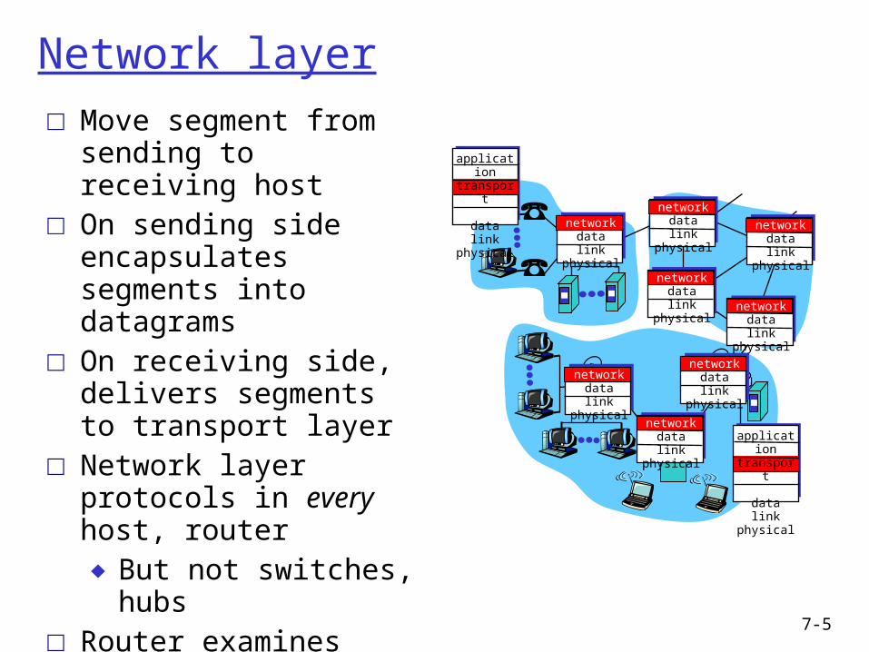
Network layer□ Move segment from
sending to receiving host □ On sending side
encapsulates segments into datagrams
□ On receiving side, delivers segments to transport layer
□ Network layer protocols in every host, router♦ But not switches, hubs
□ Router examines header fields in all IP datagrams passing through it
networkdata linkphysical
networkdata linkphysical
networkdata linkphysical
networkdata linkphysical
networkdata linkphysical
networkdata linkphysical
networkdata linkphysical
networkdata linkphysical
applicationtransportnetworkdata linkphysical
applicationtransportnetworkdata linkphysical

7-6
Two Key Network-Layer Functions
□ Forwarding: move packets from router’s input to appropriate router output
□ Routing: determine route taken by packets from source to dest.
♦ routing algorithms
analogy:
□ Routing: process of planning trip from source to dest
□ Forwarding: process of getting through single interchange

7-7
1
23
0111
value in arrivingpacket’s header
routing algorithm
local forwarding tableheader value output link
0100010101111001
3221
Interplay between routing and forwarding

7-8
Connection setup
□ 3rd important function in some network architectures:♦ ATM, frame relay, X.25
□ Before datagrams flow, two end hosts and intervening routers establish virtual connection♦ routers get involved

7-9
Network service model
Q: What service model for “channel” transporting packets from sender to receiver?
Example services for individual packets:
□ guaranteed delivery□ guaranteed delivery
with less than 40 msec delay
Example services for a flow of packets:
□ in-order packet delivery□ guaranteed minimum
bandwidth to flow□ restrictions on changes
in inter-packet spacing

7-10
Chapter 4: Network Layer
□ 4. 1 Introduction□ 4.2 Virtual circuit and
datagram networks□ 4.3 What’s inside a
router□ 4.4 IP: Internet Protocol
♦ Datagram format♦ IPv4 addressing♦ ICMP♦ IPv6
□ 4.5 Routing algorithms♦ Link state♦ Distance Vector♦ Hierarchical routing
□ 4.6 Routing in the Internet♦ RIP♦ OSPF♦ BGP
□ 4.7 Broadcast and multicast routing

7-11
Network layer connection and connectionless service
□ Datagram network provides network-layer connectionless service
□ VC network provides network-layer connection service
□ Specifically:♦ service: host-to-host♦ no choice: network provides one or the other♦ implementation: in network core

7-12
Virtual circuits
□ Call setup, teardown for each call before data can flow
□ Each packet carries VC identifier (not destination host address)
□ Every router on source-dest path maintains “state” for each passing connection
□ Link, router resources (bandwidth, buffers) may be allocated to VC (dedicated resources = predictable service)
Source-to-dest path behaves much like telephone circuit♦ performance-wise♦ network actions along source-to-dest path
7-13
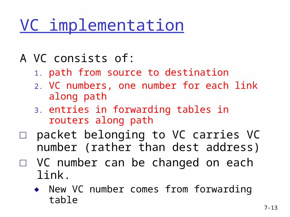
VC implementation
A VC consists of:1. path from source to destination2. VC numbers, one number for each link along
path3. entries in forwarding tables in routers along path
□ packet belonging to VC carries VC number (rather than dest address)
□ VC number can be changed on each link.♦ New VC number comes from forwarding table
7-14
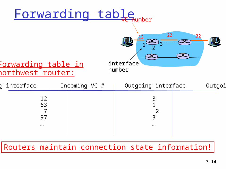
Forwarding table
12 22 32
12
3
VC number
interfacenumber
Incoming interface Incoming VC # Outgoing interface Outgoing VC #
1 12 3 222 63 1 18 3 7 2 171 97 3 87… … … …
Forwarding table innorthwest router:
Routers maintain connection state information!
7-15
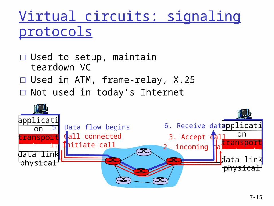
Virtual circuits: signaling protocols
□ Used to setup, maintain teardown VC□ Used in ATM, frame-relay, X.25□ Not used in today’s Internet
applicationtransportnetworkdata linkphysical
applicationtransportnetworkdata linkphysical
1. Initiate call 2. incoming call
3. Accept call4. Call connected5. Data flow begins 6. Receive data

7-16
Datagram networks□ No call setup at network layer□ Routers: no state about end-to-end connections
♦ no network-level concept of “connection”
□ Packets forwarded using destination host address♦ packets between same source-dest pair may take different
paths
applicationtransportnetworkdata linkphysical
applicationtransportnetworkdata linkphysical
1. Send data 2. Receive data
7-17
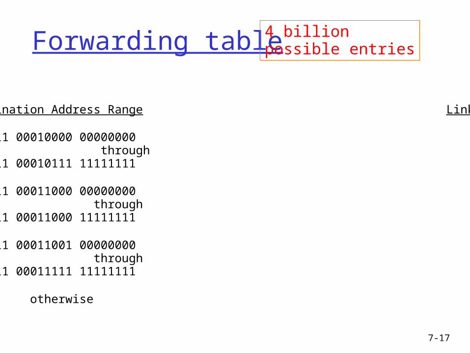
Forwarding table
Destination Address Range Link Interface
11001000 00010111 00010000 00000000 through 0 11001000 00010111 00010111 11111111
11001000 00010111 00011000 00000000 through 1 11001000 00010111 00011000 11111111
11001000 00010111 00011001 00000000 through 2 11001000 00010111 00011111 11111111
otherwise 3
4 billion possible entries
7-18
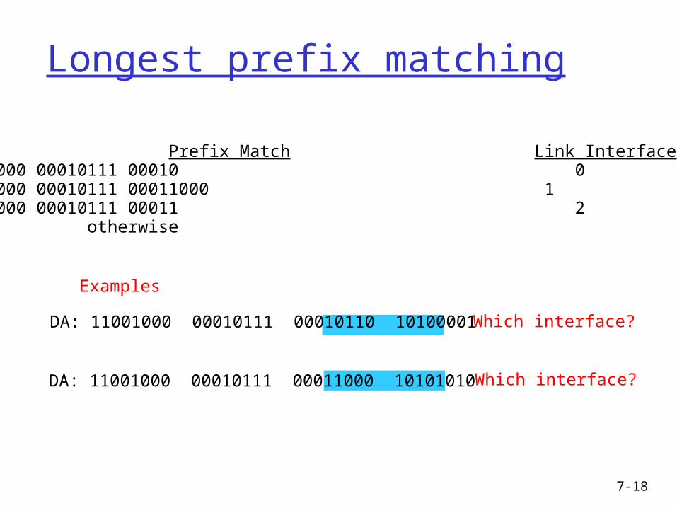
Longest prefix matching
Prefix Match Link Interface 11001000 00010111 00010 0 11001000 00010111 00011000 1 11001000 00010111 00011 2 otherwise 3
DA: 11001000 00010111 00011000 10101010
Examples
DA: 11001000 00010111 00010110 10100001 Which interface?
Which interface?

7-19
Datagram or VC network: why?
Internet (datagram)□ data exchange among
computers♦ “elastic” service, no strict
timing req. □ “smart” end systems
(computers)♦ can adapt, perform control,
error recovery♦ simple inside network,
complexity at “edge”□ many link types
♦ different characteristics♦ uniform service difficult
ATM (VC)□ evolved from telephony□ human conversation:
♦ strict timing, reliability requirements
♦ need for guaranteed service
□ “dumb” end systems♦ telephones♦ complexity inside
network

7-20
Chapter 4: Network Layer
□ 4. 1 Introduction□ 4.2 Virtual circuit and
datagram networks□ 4.3 What’s inside a
router□ 4.4 IP: Internet Protocol
♦ Datagram format♦ IPv4 addressing♦ ICMP♦ IPv6
□ 4.5 Routing algorithms♦ Link state♦ Distance Vector♦ Hierarchical routing
□ 4.6 Routing in the Internet♦ RIP♦ OSPF♦ BGP
□ 4.7 Broadcast and multicast routing
7-21
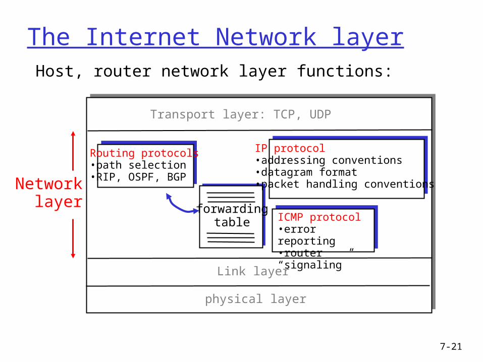
The Internet Network layer
forwardingtable
Host, router network layer functions:
Routing protocols•path selection•RIP, OSPF, BGP
IP protocol•addressing conventions•datagram format•packet handling conventions
ICMP protocol•error reporting•router “signaling”
Transport layer: TCP, UDP
Link layer
physical layer
Networklayer

7-22
IP datagram format
ver length
32 bits
data (variable length,typically a TCP
or UDP segment)
16-bit identifier
header checksum
time tolive
32 bit source IP address
IP protocol versionnumber
header length (32-bit words)
max numberremaining hops
(decremented at each router)
forfragmentation/reassembly
total datagramlength (bytes)
upper layer protocolto deliver payload to
head.len
type ofservice
“type” of data flgsfragment
offsetupper layer
32 bit destination IP address
Options (if any) E.g. timestamp,record routetaken, specifylist of routers to visit.
how much overhead with TCP?
□ 20 bytes of TCP□ 20 bytes of IP□ = 40 bytes + app
layer overhead

7-23
IP Fragmentation & Reassembly□ Network links have MTU
(max.transfer size) - largest possible link-level frame.
♦ different link types, different MTUs
□ Large IP datagram divided (“fragmented”) within net
♦ one datagram becomes several datagrams
♦ “reassembled” only at final destination
♦ IP header bits used to identify, order related fragments
fragmentation: in: one large datagramout: 3 smaller datagrams
reassembly

7-24
IP Fragmentation and Reassembly
ID=x
offset=0
fragflag=0
length=4000
ID=x
offset=0
fragflag=1
length=1500
ID=x
offset=185
fragflag=1
length=1500
ID=x
offset=370
fragflag=0
length=1040
One large datagram becomesseveral smaller datagrams
Example□ 4000 byte datagram□ MTU = 1500 bytes
1480 bytes in data field
offset =1480/8
See the fragmentation applet on UW-ACE

7-25
Recap□ Network layer
♦ Introduction• forwarding vs. routing
♦ Virtual circuit vs. datagram details• connection setup, teardown• VC# switching• forwarding tables, longest prefix matching
♦ IP: the Internet Protocol• packet structure• fragmentation & reassembly

7-26
Next time
□ ARP
□ DHCP
□ ICMP
□ IPv6