Embed Size (px)
Citation preview

CHAPTER IX.
MARK VI BREECH MECHANISM FOR 4-INCH R. F.
GUNS.
I. The 4-inch Mark VI Breech Mechanism is of service design, embodying the Welin stepped-screw principle and a modification of the Fletcher operating gear, (it is sometimes called the "Modified Fletcher" mechanism), and is fitted to the so-calibre 4-inch rapid-firin~ guns, Mark VII, from NO.213 upward, which are the only main battery rapid-firing guns building.
It embodies the following· characteristics: (a) An interrupted We1in, or stepped-thread, breech plug. (b) The plug is carried by threads on a "carrier ring" hinged to the gun yoke and swings directly out from the breech, without any movement of translation. ( c) The operation of locking or unlocking is performed by meaps of a spiral rack on the side of the plug and corresponding teeth on a segment of the hand lever hinged to the ".carrier ring." ( d) The firing mechanism is similar to the 4- or s-inch Fletcher breech mechanism, but the firing pin, being insulated, is also used for electric firing,-by a simple connection with an electric-firing cable and throwing out a " percussion catch piece" on the" sear bar." ( e) The extractor is carried in a longitudinal recess in the block itself, as in the Dashiell system, and its engagement with the head of the cartridge case is effected by a separate lip piece with a transverse movement. (f) The screw box is cut in a breech ring which screws into the jacket, abuts against the tube and is secured by set screws.
2. The Breech Plug (Plate I), 6if inches total length, has 4H inches of its forward part divided into six equal seCtions; each semicircle having a blank (2) and two stepped-threaded (3) sections. The blanks are diametrically opposite on the left and right sides, centers in horizontal axial plane. in the closed position. The stepped sections have radii of 4 and 40 inches, the higher

130 TEXT BOOK OF ORDNANCE' A ND GUNNERY
diametrically opposite to the lower, and the lower step being to the right of the blanks (going with the sun and viewed from the rear) ; these threaded sections are separated Ys inch for convenience in manufacture. The blanks, and upper part of teeth of firsfs-~, are cut concavely and convexly with the hinge pin as a center, to form clearances for swinging the plug in and out of the screw box. The nose of the plug is recessed (4) to the rear to form a clearance for the head of the cartridge case, the flange being left thereon as a continuation of the plug threads for strength; the right part of the recess is sloped away somewhat to . avoid jamming the case, if it is not pushed home.
The rear end of the plug is left cylindrical for I ~ inches on a diameter of 8~ inches, and has a square left-hand thread (7) of ;;;; inch pitch (same as plug thread) cut thereon for attaching to the carrier rirtg, except in that part where the unlocking teeth are situated. In the ENE. side of the locked position, over an arc of 60 degrees, are cut five involuted teeth inclined 45 degrees to ' the horizontal which form a plug rack (13) or unlocking teeth, and are engaged by those on the hand lever. '
The rear end of the plug is recessed out for lightness and has an axial stem (9). Through the stem and plug's axis is drilled a hole (10) for the firing pin, conical in shape at the front end and diminishing to size of the firing point. That part of the recess in which works the" cocking bar" is enlarged, leaving a shoulder ( II) there. Two vent holes (17), 34 inch diameter, leading into the front end of the firing-pin hole and extending outward into the plug recess, provide a means for the escape of gas in case of a blow back.
A slot (12) is cut through the plug in a vertical axial plane for a short distance, forming a way for the" cocking bar." In the NNE. part ( in the locked position) is cut a longitudinal extractor hole (14) inclined I 5 degrees to the axis and to the front, at the front end of which is cut a transverse clearance (IS) for the extractor head. In the rim of the plug are cut dovet~i1 slots (18) for the . sear-bar lug, inclined IS degrees to the horizontal. On the left side there is a cut in the thread of the carrier ring, forming a recess (19) for the toe of the" plug retaining plunger."
3. The Carrier Ring (20) is designed to carry the breech plug

BREECH MECHANISM FOR 4-INCH R. F. GUNS 131
and hand lever. It is a circular cast-steel ring, suitably hollowed out in the front side for lightness, sloped off into an arm on one side which curves to the front and has a vertical hinge-pin hole (21), center 10 inches from the center of the ring. The right end of the arm fits between hinge lugs on the right side of the gun's yoke, and the hinge pin (33), passing through the hole in the arm and hinge lugs, hinges the carrier to the gun. A boss is so cut on the arm las to leave a shoulder (32), which brings up on the yoke, limiting the extent the plug is opened, viz., at a right angle to the gun's axis. A slot (23), center in horizontal axial plane, is cut through the ring, and a vertical hole (22). passing through its arm is for the operating-lever pin (34) .
. The inner surface of the ring has cut therein a square left-hand thread (24), into which screws the corresponding thread of the plug. A camgroove (25) for the cocking bar is cut within the ring, in the threads, on diametrically opposite sides, opening at points 60 degrees to the right of the vertical line. There is a recess (27) for the plug-retaining plunger (28). One-half inch above the horizontal axial plane, on the left side, is secured the" handlever · catch piece" (26). At (30) and (3 I) are clearance cuts for the sear bar, for firing and cocking, respectively.
4. The Operating Lever (3S) is a flat bar, provided with a vertical handle (36) on the left end, and a segment of a circle on , the right, in which is a hole for the lever pin which pivots it to \ the carrier ring. On the front and inner surface . (in closed position) are cut eight 4S-degree teeth (38), which engage the plug's rack teeth (13) and by which the plug is rotated to lock or unlock. The front edge of the bar is cut out (39) to clear the sear bar when closed and is scored for lightness; near the center the lever has its full width and a longitudinal hole (40) is drilled for the " electric contact sleeve."
The handle (36) consists of a stud (36a) screwed into the left end of the lever, over which works a sleeve (36b). The lower end of the sleeve is screwed into a lever catch (37), which surrounds the stud next to the lever. A helical spring (36d), with one end fitting into a groove in the sleeve and the other in the stud, always tends to revolve the lever catch to the right. The end of this catch is provided with a hook, which will engage the

,"
4-INO-l BREECH MECHANISM , MARK VI.

132 TEXT BOOK OF ORDNANCE AND GUNN~RY
lever-catch piece on the carrier when the hand lever is fully closed. A small limiting slot (37a) in the catch and a pin-screw stud (37b) screwing into the lever prevent undue revolution of the lever catch.
5. The Firing Mechanism consists principally of an insulated firing pin, firing-pin sleeve, cocking handle, firing-pin spring, a cocking bar, sear bar, trigger mechanism, and electric contact connections. The firing pin (42) is a straight circular rod with the usual conical head and point, threaded at the rear end for a nut (43), and is surrounded by a vulcanite bush (44) and a vulcanite washer against the head and in front of the nut. A steel sleeve (45), with a collar at the front end and threaded at the rear end, surrounds the insulation and lies between the two insulating washers; this sleeve, with the insulation, is kept in place by the nut (43) screwed on the rear end of the firing pin.
A cocking handle (46) is screwed on the rear end of the sleeve and is retained there by a set screw (48). On the right side of the handle's hub (in the assembled position) is a cock notch (47) for the sear bar. The end of this handle works in the lower cut for the cocking bar in the plug rim and acts as a guide to keep the cock notch in the proper position. The (spiral) firing spring (49) surrounds the sleeve and lies between the collar on the latter and the cocking bar.
The cocking bar (So) is quite similar to the 4- and s-inch Fletcher; it works over the firing-pin sleeve, forward of the cocking handle, and its ends take in the cocking grooves (25) in the carrier ring. The insulated firing pin, sleeve, firing spring, cocking bar, and cocking handle are assembled as one piece, as in the 4- or s-inch Fletcher mechanism, the spring being under a slight initial compression.
The sear spring (56) and sear bar (51) are very similar to those of the 4- and s-inch Fletcher mechanism, and work in the same way. There is an oblong hole (SIa) near the center of th<: bar through which the rear end of the firing-pin sleeve passes; it is recessed out to clear the hub of the cocking handle. There is a separate piece on the front side of the bar to right of the hole, to form a " cocking catch" (52) or lip for percussion firing, which is retained and pivoted on the bar by a screw (53). This catch

BREECH MECHAXIS~1 FOR 4-li'\"cH R. F. GGNS 133
may be turned up 90 degrees (by turning it with the finger) so that the cock notch of the firing pin will not be engaged, when it is desired to use the electric firing mechanism. To keep this cocking catch piece in either position, there is provided a lock (54) consisting of a small spring plunger (54a) seating in a hole on the front side of the bar, and worked by a spring (s4b) ; this plunger will enter a recess in the cocking catch in the two 90-degree positions. The left end of the sear bar, when the plug is dosed, slides behind a lip on the lever catch piece (26), and prevents rear displacement by the trigger bar; the left edge of the bar is beveled for the sliding trigger bar.
The trigger mechanisl1~ consists of a box (63) held in a dovetail groove cut in the gun on the left side, on a line IS degrees above the horizontal by a spring bolt (64a) entering the recess. A" trigger lever" (65) is pivoted near the middle within the box, its inner end bearing on the foot of the trigger bar (67), which slides fore and aft in a dovetail groove, and has a foot against which bears a spiral spring (68), seated in a recess in the box, tending to keep it in its forward position; on the after end of the trigger bar is a beveled surface. When the outer end of the trigger lever is pulled forward, the bar is moved aft, and it~' beveled surface bearing on the sear bar moves the latter to the right far enough to disengage the firing pin.
The electric firing wire is connected to a contact piece, so carried in the operating lever that it will iie in the axis of the bore when the breech is closed. The wire is secured to the rear end of a contact piece (59) which is held in an insulated sleeve (58); this sleeve is capable of considerable longitudinal motion against the action of a spring (60). The spring wiIi, when the firing pin is not cocked, press the contact piece against its head, completing the electric circuit; when cocked for percussion firing, the spring yields enough to permit the lever to dose. Thus the same firing mechanism is used both for percussion and electric firing and the gun may be fired by either means without dismounting anything. Combination primers are used.
6. The Extractor (69) consists of a lever (70) or tail, lip piece (71) and screw (72), spiral spring (73) and retaining pin. The front end of extractor has a double-lipped guide slot for the lip

134 TEXT BOOK OF ORDi"ANCE AND GUNNERY
piece (71) at right angle to the tail. The tail of the extractor works within the inclined hole (14) in the plug, which keeps the extractor in the plug. A lip piece, sliding in the lipped groove on the front end of the extractor tail, has a small right and left movement, and is retained by a screw pin (72) through an oblong hole. A spiral spring (73) is placed in a recess on the underside of the lip piece and bearing on the end of the groove. The extractor tends always to keep the lip piece engaged under the rim of the case. A longitudinal slot (7od) is cut in the tail, through which passes a pin (74) at the front end of the extractor hole and enters a recess in the plug.
7. The Action of the Breech Mechanism.-(Supposing the breech closed). To open: Grasp the handle of the operating lever, turn it to the left to disengage the lever catch from the carrier, then pull to the rear. The spiral threads on the lever engaging those of plug rack will rotate the plug to the right to unlock. While the plug is being unlocked, the ends of the cocking bar working in the grooves of the carrier ring will move the bar to the rear, and with it the firing pin, until the cock notch is engaged by the catch on the sear bar. The latter is able to move to the right sufficiently to allow the lip of the catch to ride up the bevel of the notch by means of the cocking clearance (3 I) in the ring. At the moment the plug is unlocked, the upper end of the square threads for the carrier will bring up on the top of the lever segment and stop the rotation, and the lever, piug, and carrier will then swing out together on the hinge pin as an axis. As soon as the carrier clears the breech face, the plug-retaining plunger (28) springs forward and its toe enters the cut (19) in the plug, preventing any movement of rotation of the latter within the ring when the direction of the lever's movement is reversed. As the plug swings out from the screw box, the extractor's tail, working in the inclined hole in the plug, will cause the extractor to move about its fulcrum , bearing on the side of screw box, throwing the inner end of the lip piece to the rear and prying out the case with great power. As soon as the plug has traveled to the rear the length of the slot in the extractor lever, the extractor brings up on its keep pin (74) anel the plug and extractor move in unison to the rear, withdrawing the case until the lip piece slips off the

BREECH MECHANISM FOR 4-INCI-I R. F. GUNS 135
rim of the cartridge case. ·When the lever ha£ swung about 190 degrees, the shoulder (32) on the carrier brings up on the hinge yoke and stops the movement. The rear face of the plug is then parallel to the axis of the bore.
To close: The movement of the lever is the reverse. When the retaining plunger (28) in the carrier ring strikes the breech, its toe moves to the rear and releases the plug, and as soon as the carrier strikes the breech face of the gun, the center of movement of the lever is transferred from the hinge pin to the lever pin, and the spiral teeth of the lever rotate the plug to the left, locking the same into the screw box. During the plug's rotation, the cocking bar is moved forward by the grooves (25) in the ring and, the firing pin being held by the sear bar, the firing-pin spring is compressed. When the plug is fully locked, the operating lever is latched to the carrier by the catch (37) engaging that on the carrier, and the left end of the sear bar is in contact with the trigger bar. To change from percussion to electric firing when the firing pin (42) is cocked without opening the breech, first pull the cocking handle (46) a short distance to the rear to release the cocking catch piece (52) from the safety notch (52a) so as to clear the cock notch on firing pin, then allow the firing pin to go forward slowly. If it had been intended in the first place to fire by electricity, the cocking catch should have been pushed to the right before closing the breech; then the sear bar would not have held the firing pin and it would have been merely pushed against the primer by the cocking bar without compressing the mainspring. Now if it be desired to change to percussion firing, without opening the breech, it is only necessary to push the cocking catch over to the left, grasp the cocking handle and pull it to the rear, compressing the firing spring, until the sear bar snaps over the firing pin head. Obviously there can be no electric connection to the primer when cocked for percussion firing, and when the firing pin is forward in contact with the primer the main spring is not COlll
pressed. The electric contact piece (59) in the lever should always remain
in the same place, as it requires no adjustment when changing from percussion to electric firing.
To fire: If the percussion mechanism is used, pull on the lan-

136 TEXT BOOK OF ORDNANCE AND GUNNERY
yard attached to the outer end of the trigger lever. The trigger bar will move to the rear, and its beveled surface will move the sear bar to the right sufficiently to disengage the firing pin, which will fly forward under the action of the compressed spring and strike the cap of primer.
8. Points of Safety.-The gun cannot be fired before the plug is fully locked: first, because the sear bar cannot move to the right to disengage the firing pin until the firing clearance (30) in the carrier ring is reached, except in the unlocked position when there is no compression on the firing spring; second, if the electric mechanism is used, there is 110 contact between firing pin and primer or between contact piece and firing pin until the operating lever is fully closed.
The plug will not unlock on firing; first, because the position of the lever is beyond the center of movement to the rear; second, the hand-lever catch prevents the lever the movement which is necessary if the plug rotates.
The firing mechanism will not be injured if an escape of gas occurs, as gas vent holes (17) are provided in the plug to relieve the firing pin.
3-inch R. F. Breech Mechanisms.
9. There are now in service or under construction 261 3-inch R. F. guns; at the time of writing it is intended to build all subsequent 3-inch guns on some semi-automatic principle. While 3-inch guns are properly designated as secondary-battery guns, their breech mechanisms are more in resemblance with those of the main battery. Mark I 3-inch mechanism is a Fletcher mechanism fitted to the field pieces. Mark II has a modified Fletcher operating gear similar to the 4-inch mechanism described above and is fitted to 16i 50-calibre 3-inch guns. 1\1ark III has a system of operation somewhat resembling the Dashiell system and is fitted to 100 3-inch 50-calibre guns built by the American· Ordnance Company. All 3-inch guns are fired only by percussion.
ro. 3-inch B. M. Mark II (Plate II) .-This mechanism is similar to the 4-inch mechanism just described but differs principally as follows: (a) The breechblock is of the ordinary or un stepped type; (b) the block, instead of being held inside the

BREECH MECHANISM FOR 4-INCH R. F. GUNS 137
carrier, is screwed over a boss projecting from its surface, in which the cocking bar works in the " same manner; (c) opening or closing is likewise accomplished in two ;:notions, rotation, and swinging_ (portions of the block and screw box being sloped away to permit it), but the operating lever is pivoted on the carrier hinge pin and only one center is used; (d) the hinge pin, trigger box, etc., are held by a hinge plate (A) bolted to the breech of the gun; (e) the extractor is like that of the ordinary Fletcher mechanism.
tI. The Breech Plug (I) is chased with a left-hand abutment thread, divided into six equal sections, three of which are planed out to form blanks ( 3) . The threaded sections ( 2) are on the left, upper right, and lower right quadrants in the closed position. The left blank of the plug and the two left blanks in the screw box are cut away to form a clearance (4) for swinging out on the hinge pin (25) as a center. The rear part is hollowed out axially to form a cylindrical recess (I I), the bore of which is chased with a square left-hand thread of the same pitch as the plug thread; the boss of the carrier plate screws into this thread (19). On the right side of the rear face of the plug is bolted a separate segmeny,. covering 60· degrees of arc, on the surface of which are cut 45-degree angle teeth, forming the rotating segment (14) and rotating teeth (I4a); diametrically opposite is cut a circular groove, center in axis of plug, called the safety groove (9), in which enters the safety toe (4Ib) of the sear bar to prevent firing the gun in any but the fully closed position of the breech plug. This is accomplished by having the groove run in radially to the recess in the plug only at the two ends of said groove. A r·ecess for the plug-retaining catch (10) is provided on the left side of the rear face, so that when the plug is rotated to the unlocked position, the plug-retaining catch (22), carried by the carrier plate, ,springs in and secures the plug from any rotation during the" swing" out or jn, with the carrier (15), on the hinge pin (25). The axial firing-pin hole (13) and stem (12) are similar to the Fletcher type.
I2. The Carrier (IS) is a flat circular plate having two jaws on the right side containing the hinge-pin hole; it is hinged by the pin (25) to the hinge plate (A), the slot (17) between the
IO

138 TEXT BOOK OF ORDNANCE AND GUNNERY
jaws being for the operating lever. On the forward side in the center is a cylindrical boss (19) having cut thereon a square lefthand thread, of plug thread pitch, on which is screwed the breech plug. The boss is hollow and has cut in its inner surface two diametrically opposite cocking-cam grooves (20) for operating the cocking bar (40) of the firing mechanism, (similar to the Fletcher 5-inch). In the horizontal center line a. slot (r8) is cut through, partly dovetailed at the right and left ends, in which works the sear bar (41), and on the right side is formed a seating for the sear spring as per figure. On the rear face, left side, just above the sear bar, is a catch (24) for the operating lever's latch. On the forward side, opposite to the upper end of the left screw-box thread, is a recess containing a plug-retaining catch (22) within which is a spiral spring (23) which operates the former, so that when the plug is unlocked and the carrier swings from the breech face, the plunger (22) is forced into the recess (IO) in the plug.
13. The Operating Lever (26), working on the (carrier) hinge pin (25) within the jaws of the carrier, is provided with a segment (30) on the right inner side of which are cut a number of 45-degree angle teeth (30a) to engage those of the rotating segment (14) on the plug, and by which the plug is locked or unlocked. The back of the lever at the right , end forms a cam surface (28) for operating the extractor (35) as in the case of the Fletcher breech mechanism; underneath this surface is worked, solid with the lever, a lug (29), which, bringing up on the outer surface of the gun when the breech is opened, acts as a stop and prevents a blow on the extractor pin. On the left end of the lever is a handle (31) or hand grasp; the handle is provided with a (bell crank) lever latch (32) pivoted at the bend, which snaps over the catch (24) on the carrier when the breech is fully closed, through the action of the spiral spring (33) and plunger (34), as per figure. This prevents thd breech from opening at any elevation, shock of the charge, or accident, and therefore must be deliberately freed by pressure of the hand when it is desired to open the breech.
The extractor (35) is similar to the Fletcher, though somewhat more bent, and is placed and operated in a similar manner.

BREECH MECHANISM FOR 4-INCH R. F. GUNS 139
14. The Firing Mechanism--percussion firing is exclusively used-consists of firing pin, firing spring, cocking bar, cocking handle, sear bar with sear and sear spring, and trigger box, and is very similar to that of the 4-inch Mark VI mechanism. The firing pin has the usual conical head (37) and on its rear end is screwed a nut (38) which is provided with a cock notch and a cocking handle (38a), extending to the rear through a guide-slot in the carrier, which prevents its turning. The firing spring (39) surrounds the firing pin between its head and the cocking bar (40) which lies in a slot through the stem (12) by which it is forced to rotate with the block; its ends engage the cam grooves (20). The firing pin may be eased down from the position of full cock, when the breech is closed, by the cocking handle or the mechanism may be recocked by it, without opening the breech. The sear bar (41) slides to the right and left, against its spring (42), within a slot in the carrier and its only connection with the block is by the safety toe (4Ib); the sear, (4IC) engages the firing pin when cocked and releases it when the trigger presses the bar to the right. The safety toe is a projection on the left forward side of the sear bar which works in the safety groove (9) of the ~lug in such a manner that the sear bar can be forced to the right, only in the fully closed position, to permit firing and, in the unlocked position, to permit the sear to snap into the cock notch of the firing pin. The trigger mechanism is quite similar to that of the S-inch Mark II breech mechanism (Fletcher No.2) except that the trigger box (43) is secured by a screw (44) instead of a spring catch.
15. The Operation of the Mechanism is as follows: The breech being closed, to op~n, grasp the handle of the operating lever, compressing the upper arm of the lever latch to release the same from the catch on the carrier, then swing smartly to the right until the stop (29) brings up on the right side of the gun. When the lever has swung 61 degrees the rotating teeth have revolved the plug to the unlocked position, the rotation being stopped by the lower edge of the plug's rotating segment striking the end of the circular cut in the screw box, provided as a clearance for it; the plug-retaining catch is now directly in line with the recess in the plug. During the rotation the cocking bar is brought to the
CHAPTER IX. PLATE II.
&'1/' . :.-
, .. -
Plug retaining catch. 9
PLUG UNLOCKED PLUG LOCKED
/?:-~_3
1U
3 1'4"
3-INCH BREECH MECHANISM, MARK II.
140 TEXT BOOK OF ORDNANCE AND GUNNERY
rear through the action of the cam grooves (20), as it is forced to turn with the plug by reason of the guide slots OIl the plug stem, and with the cocking bar comes the firing pin until the cock notch (38b) engages the nib (4Ic) of the sear. The further swing of the lever of 100 degrees swings the carrier and plug out from and clear of the screw box, and the moment the carrier leaves the face of the breech the retaining plunger springs into the recess (9) in the plug, locking the latter from movement on the carrier boss. The extraction takes place during the whole of the swing-open movement, slowly at first, then more rapidly.
To close: The reverse movement is given to the operating lever until the lever is folded across the breech and held by the latch. The plug-retaining catch releases the plug the moment it strikes the face of the breech, permitting the plug to revolve to the locked position; during the revolution the cocking bar is moved forward, compressing the firing-pin spring (39). When the breech is fully closed the plug is locked in the screw box, the lever is latched to the carrier, the left end of the sear box is in line with the trigger, and the safety toe (4Ib) is opposite one of the cuts in the safety groove.
To fire: On pulling the lanyard attached to the outer arm of the trigger the sear bar is moved to the right, releasing the firing pin, which flies forward under the action of its spring and strikes the primer of the cartridge case. The sear spring returns the sear bar to the original position. Should a missfire occur, the firing pin may be recocked by pulling to the rear on the recocking handle.
16. Safety.-(a) Premature discharge is impossible because the firing spring is not compressed and the sear bar cannot release the pin, until the breech is fully closed; (b) the breech will not open at any angle of elevation because of the hand-lever latch, nor can it be accidentally opened; (c) the breech will not open on firing, because of the reverse action of the lever on recoil as well as the natural friction of the plug and spiral threads.
The Mark III 3-inch Breech Mechanism.-(Plate III gives various complete and partial sections. Plate IV shows the entire mechanism dismounted, and Plate V shows the assembled mechanism closed and open.)

BREECH MECHANISM FOR 4-INCH R. F. GUNS 141
17. The Mark III mechanisni has little similarity with that of other R. F. guns, but has an operating gear somewhat like the Dashiell system. It is to be noted that: (a) The block is secured to a boss on the carrier as in the Mark II mechanism, and after rotation also swings open on the carrier hinge pin; (b) the extractor is not a part of the block; it is secured by the carrier hinge pin, but does not swing on it as a center; (c) the cocking and the compression of the firing spring are both accomplished' during opening.
The principal parts ·of the mechanism are, the breech block with rotating, locking and stop studs, the carrier, the operating lever and lock, the extractor and cam and the firing mechanism, (percussion firing only is employed).
18. The Breechblock (IO) has four threads and four blanks; the blanks are, when the block is locked, at top, bottom and sides. The right and left blanks of the screw box are curved as shown in order to permit swinging without translation. The breechblock is hollowed from the rear to receive the firing case, and is provided with a suitable bayonet joint in which the corresponding lugs on the firing case lock. On the inner surface of the block is the cocking cam (IO D) seen in projection Fig. 6, Plate III. On the rear " face of the block hub is the block safety lug (IO E) , seen in Fig. 5, Plate III, and in Plate IV. The threads on the block, seven in number, are blanked to correspond with the threads in the screw box; the rear thread of all is left continuous and acts as a stop thread. A small recess (IO H) is cut in this thread for the blocklocking plunger. The block-stop stud (IO B), and block-rotating stud (IO C), are screwed in to the rear face of the block.
19. The Hinge Plate (12) is secured to the right side of the gun by four large screws. The hinge pin (17) passes through the upper carrier hinge lug (II B), the upper hinge-plate lug (12 A), the extractor (18), the extractor cam (19), the lower hinge-plate lug (12 A), the operating lever (16), and the lower carrier hinge lug (II B).
The carrier (II) has on its lower side a transverse horizontal recess (lID), the rack slot; above the rack slot is the extractor cam seat (II C) (Fig. 4, Plate III). The carrier is bored through its rear face at a point concentric with the bore of the gun
FiG.5 FIG.6
r20"" ~ '~'_ '4...\_,
" ,-, . ""
·r········i ""'"
-:~~t~~'" , ' i II
\ r -" -'-'-zi"o \.rZ'" ., ,
".
i ~ ,, ', ! I " 115 -' .,
FIG.2 /
./
./
":i~'~:;'~::':' ::>:'\:;., (".,
t. : ...
· 20~.~
, , , , , , '
-' 17
Iv·· ..... ...,..... ....
20
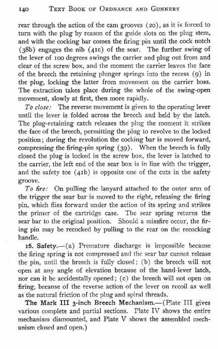
Fig. 1.-Horizontal section through center of breech of gun, and a partial section of the breech block.
Fig. 2.-Rear elevation of breech. Fig. S.-Vertical longitudinal section through center of
breech block. Fig. 4.-Side elevation of breech mechanism. Fig. 5.-0utline sketch of rear elevation of sear and hub of
breechblock.
, , , '.
"',., ,· .......... _._. ___ . ...,1#-· .. , ... ' "A •
........ ... '~ .... ..... #/
Fig. 6.-Side elevation of same.
FIG.?
,. ".
F1G.4
'7
'10 o
Fig. 7.-Vertical transverse section through bayenet lugs of firing case and through firing pin.
Fig. S.-Longitudinal section through center of block-locking plunger. This section is inclined 45° from the vertical.
Fig. 9.-Breech open.
() :r ~ "D -i m ::0
?< "D r ~ -i rn
;-

142 TEXT BOOK OF ORDNANCE AND GUNNERY
to receive the breech-block hub, and has on its forward face a boss ( I I A) which assembles in a corresponding annular recess in the rear face of the block. On the rear face of the carrier and to the left of the hole for the breechblock hub is a shallow clearance cut for the sear safety lug; this cut is seen to the left of (21 D) (Fig. I, Plate III). On the left side of the carrier is a longitudinal slot in which the toe of the sear rests (see Plate IV). On the forward face of the carrier is the block-stop slot (I IE) and in the upper left hand side, a seat in which rests the locking bolt (I I F) ; this bolt, pressed forward by its spring, drops into a recess in the · block as the unlocking is completed.
20. The Operating Lever (16) is a long arm, without a handlelocking device, pivoted on the hinge pin in a slot in the lower part of the carrier; it has a stud (16 B) on its lower side which operates the rack. The rack (20) is attached to the breechblock by the stud (10 C) which. works in a slot (20 A) in its left end by which, when the rack is moved to the right or left, the block is rotated.
2I. The Firing Case does the double duty of containing and guiding the firing mechanism and of securing the block to the carrier. The head of the case is made large to give ita bearing on the carrier; it passes through the latter and, engaging the bayonet joint of the block, locks the two firmly together. (Since there is no screw thread action in this device the carrier will move up to or away from the gun as the block is rotated.)
The firing case (13) is a stepped cylinder, hollowed out to receive the firing pin (14) and the firing spring (IS). On its rear end it has a projecting lug which is slotted to recei¥e the sear (2 I) ; the cylindrical portion is slotted for the firing-pin guide rib. On the stem of the case are two bayonet lugs which serve to lock it to the block; in the sear slot there is a lug which furnishes a bearing for the outer end of the sear spring (22).
The firing pin (14) is a hollow cylinder, partially closed at its forward end and having a guide rib (14 B) ; this guide rib, toward its rear end, projects into a lug on which is the cocking-lug (14 C) and the cock notch (14 D). The firing point (30) has a split shank and is assembled with the firing pin by simply pushing the shank into the firing-pin head (14 A) . The firing spririg (IS) is spiral;

BREECH MECHANISM FOR 4-INCH R. F. GUNS 143
its forward end abuts against the forward end of the cylindrical recess in the firing pin, its after end abuts the after end of the firing-pin recess in the firing case.
The sear (2 I) is shaped to travel in the sear slot in the firing case. It is hollowed out to receive the sear spring (22), one end of which abuts against the lug in the firing case, as before described, and the other end of which abuts against the inner end of the sear-spring reces:s in the sear. The sear-guide ribs (2I B) travel in corresponding ways in the firing case, and prevent the displacement of the sear. On the inner forward side of the sear is the sear safety lug (21 D) which, when the block is not completely dosed, engages the block safety ) ug (10 E) (Plate III, Fig. 5), and prevents the sear from being withdrawn far enough to release the firing pin. The sear cock notch (21 C), the sear toe, which engages the trigger toe (23 A), and the sear finger catch are plainly shown in the plates. The firing case is inserted at an angle of 90° to its final position, pushed in until the bayonet joint " takes" and then turned to the left until its toe snaps into the slot in the edge of the carrier.
22. The Extractor (18) i8 best shown in Fig. I, Plate III, and in Plate IV. The hinge pin passes through the extractor guide slot (18 C) ; the under side of the extractor, contiguous to the extractor guide slot, is cut away to the extractor cam surface (18 D). On the forward side of the extractor is the extractor pivot groove (18 B). The e_'rtractor cam (19) is shown in Plate IV assembled with the carrier; it is held in place by the hinge pin which passes through it. It has no 1110tion relative to the carrier, and its outer surface bears against the extractor cam surface.
23. The Operation of the Mechanism is as follO\vs: To open: The gun having been fired, the first movement of the operating lever causes the operating lever rack stud (16 B) to press against the corresponding slot (20 B) in the rack and produce a movement of the rack to the right. The rack being in engagement with the block-rotating stud. the block rotates until the block-stop stud (10 B) brings up against the end of the block-stop slot (II E), so that the block can rotate no farther: the rotation of the block is to the left and about the firing case, which remains rigid with the carner. The cocking lug on the firing pin lies, during the rotation

CHAPTER IX. PLATE IV.
ar
'"
(0
'" ,
~ (J)
z « :r: o llJ ::!E :r: o llJ llJ 0:: m :r: o z ch
~ 0:: « ::!E LL o (J)
f-0:: « a.

L: __ .. __ ..... __ _ .
I
CHAPTER IX. PLATE V .
ci w (/)
o .J (,)
I (,) w w a:: en z => (!l
LL o o z w a:: « w a::
i w 0.. 0
I (,) w w a:: en
Z => (!l
LL 0 0 Z W
0: « W a::
~.

144 TEXT BOOK OF ORDNANCE AND GUNNERY
of the block, against the cam on the inner surface of the block hub. The rotation of the block, therefore, carries the firing pin to the rear, compressing the firing spring and camming out the sear until it engages the firing-pin cock notch (14 D) (Fig. I, Plate III). After the rotation of the block is arrested, the further movement to the right of the operating lever causes the carrier, and with it the block and firing case, to swing clear of the breech.
As soon as the carrier leaves the breech, the block-locking plunger (28) (Fig. 8, Plate III) springs into the recess in the block-stop thread and locks the block against rotary- movement until the carrier is again swung to.
As the carrier revolves away from the breech end of the gun, the extractor cam, working on the cam surface of the extractor, causes the outer end of the extractor to move forward. The extractor then acts with great leverage on the cartridge head, the fulcrum being the forward inner edge of the extractor mortise (see Fig. I, Plate III). The carrier swinging still farther to the right, the outer end of the extractor is pushed so far forward that the fulcrum shifts to the extractor pivot (12 B). This results in less leverage and more velocity on the nib of the extractor; the final movement of the extractor nib is its swiftest movement and results from the shape of the extractor cam 19.
To close: The first movement of the operating lever to the left swings the carrier to until the stop thread of the block brings up against the first thread of the screw box. The block-locking stud at the same time strikes the edge of the screw box and is forced to the rear, releasing the block. A further motion of the lever will now rotate the block until the block-stop stud reaches the other end of the slot and the block will be in its locked position with the sear engaged with the trigger. (The trigger and its box are similar to that of the lVlark II mechanism except that the motion of the sear in firing is outward.)
24. Safety.-Premature firing is impossible because: (a) The block safety lug (10 E) lies to the left of the sear safety lug, preventing release of the firing pin by any cause, and the sear is not engaged with the trigger, until the plug is locked. (b) If, through the breaking of the sear cock notch, firing-pin cock notch, or either of the safety lugs, before the breech ~s fully closed, the firing pin

BREECH MECHANISM FOR 4-INCH R. F. GUNS 145
is released, the firing-pin cocking lug (14 C) will bring up on the cocking cam (10 D) before the firing point touches the primer.
25. The English-bU1lt cruisers " Albany" and " New Orleans" at present are )armed with Elswick 4.7-inch and 6-inch R. F. Guns. Their breech mechanisms are operated in a manner which to some extent resembles that of the 3-inch Mark III described above. The system is briefly described as follows: (See Plate VI.) The conical breechblock is supported by and turns on a forward projecting circular boss of the carrier, the plug being recessed for the purpose. The carrier is hinged to the right side of the gun. A guide-bolt stud passing through the plug into a groove in the boss prevents the plug from coming off and limits the rotation.
A horizontal hand lever having a handle on the left end is hinged at the right end by a vertical pin to a lug on the carrier. In a transverse slot in the carrier beneath the boss slides a block, in which fits a rear projecting "rotating pin" on the rear face of the plug. The block is connected to the hand lever by a short link, called the" rotating link."
The breech being closed, by pulling the hand lever to the rear, first, the rotating link pulls the sliding block to the right, a6d thus revolves the plug on the carrier's boss to the unlocked posi- • tion, the revolution being stopped by the plug's guide bolt; second, . the center of movement is now transferred to the carrier's hinge pin and the plug and carrier then swing out clear of the screw box on the hinge pin as an axis. At the moment the carrier clears the breech face of the gun, the plunger of a spring catch, contained in a box on the left side of the carrier, is freed and the latch enters a cut in the plug rim, preventing any revolution of the plug in the carrier while out of the screw box.
26. The cruiser "Baltimore" is to be armed principally with 6-inch 'R. F. guns constructed by the Bethlehem Steel Co. The breech mechanism, called the Bethlehem Breech Closure, employed in these guns, is operated by a gear somewhat similar to that of the 3-inch Mark III mechanism. The breechblock, as in the Vickers' mechanism, has a holding surface comprising about twothirds of the circumference, 'and it is slightly coned to facilitate swinging without translation. The blank portions of plug and screw box are cylindrical, but the threaded portions are involutes

CHAPTER IX. PLATE VI .
~ ~ ~
0 z ~ ,
.1l <t: I <.) w ::E
I <.) w w a: ID
~ <.)
~ (J) ...J W

146 TEXT BOOK OF ORDNANCE AND GUNNERY
of circles which insures a firm and even contact. The threads have no pitch, or are collars, and hence give no motion of withdrawal to the block while rotating; this motion is obtained from the form of thread on the hub of the carrier by which the block is secured. This is possible only because the collars begin to disengage as soon as they start to revolve and may move to the rear
BREECH CLOSED. BREECH OPEN.
Collars on Block and Gun Engaged. Block Free to Swing.
slightly even when the unlocking is only begun; this feature should also eliminate much friction and make rotation easy. An advantage claimed for this form of 'block is that it has no tendency to unscrew with ordinary or even excessive powder pressures; this is evidently tl,le case since the normals to the threads are parallel with the axis of the bore and there can be no rotating moment.

CHAPTER X.
THE DRIGGS-SCHROEDER R. F. BREECH MECHANISM.
1. The Driggs-Schroeder mechanism belongs to the rotary block system of breech closure in which the block rotates on a horizontal transverse axis, the upper part of the block falling to the rear; a slight vertical motion is required in locking and in unlocking, in which respect the system is the same as that of the sliding wedge.
The Driggs-Schroeder mechanism is used in the service in 1-
pounder, 3-pounder, 6-pounder, and in two 4-inch R. F. guns, all of which use the service ammunition. As all secondary battery guns to be built in the future will be of the semi-automatic or automatic type, no more D.-S. guns are being constructed. There are three marks; the first two differ considerably, while Mark III differs from Mark II only in the operating lever. All three are r
shown on Plate I. The principal parts of the mechanism are: the breech block; the
guide bolts; the axial bolt and main cam; the operating lever with its locking device; the extractors; and the firing mechanism.
2. The Breechblock (I), an irregularly shaped piece of steel, houses in the rear end of the gun's jacket, which is open at the rear and the under sides only; the sides of the housing, called the curtains, extend downward and terminate in the plug rest (23). The locking is effected and the shock of discharge taken by the engagement of the bands (I A) in corresponding grooves in the sides and top of the housing. The bands of the plug and the grooves of the jacket are inclined about 20 0 to the front so that as the block is pushed up into position in locking it is also pressed forward, forcing the cartridge case home, and in unlocking it readily detaches itself from the case. The top of the innermost band is sloped away in order that the block may unlock and swing backward with a minimum of downward motion. The firing pin

148 TEXT BOOK OF ORDNANCE AND GUNNERY
recess (I D) is mortised out from the front and below, and, connecting with it by a narrow groove, a cavity is cut in which the main cam (9) operates; the surfaces (Ib) on which the cam bears, are essential to the operation of the block, as is the rounded portion (2); (IC) is a three-cornered piece of steel riveted in place and the cam bears on its upper surface during the first step in unlocking.
The front face of the block is closed by the dove-tailed face plate (3) ; in the Mark I mechanism it is retained in place by the screwed plug (4); in subsequent marks the straight sear spring (21), being inserted from the front through block and face plate, serves as a face-plate keeper as well as a sear spring. The sear (19) works in a vertical slot in the rear face of the block which in the Mark I mechanism also affords a recess for the spiral sear spring (21). The guide bolts (8) are screwed through the curtains of the breech and their ends take in the guide-bolt grooves ( 1 g) of the block; these grooves are cammed surfaces so shaped that the guide bolts give proper direction to the motion of the block induced by the main cam; in most mechanisms the grooves are continued to the front of the block (as shown in Mark II), and in no case do the guide bolts retain the block in place in the gun, that being a function of the axial bolt ; in the Mark II type and in many of the Mark I mechanisms the block may be dismounted without screwing out the bolts.
3. The Axial Bolt (5) is cylindrical except for the hexagonal portion that engages the main cam-the right end of the bolt is of greater diameter than the left end. The bolt passes through both curtains of the breech and through the block; the hole in the latter is lengthened in a nearly vertical direction to permit the block to descend in unlocking. The main cam (9), an irregularly shaped piece of metal, rotates with the axial bolt; its working surfaces are on its rear and upper sides and the notch (9b) catches the rounded portion (2). The top is slotted out to form a cammed groove which presses the firing pin rearward by acting on its projecting portion (ISb).
4. The Operating Lever (7), on the left of the breech, differs in the three Marks, in its locking device; in Marks I and II, it has from the closed position a slight free motion before the axial bolt starts.

THE DRIGGS-SCHROEDER R. F. BREECH MECHANISM 149
In the Mark I device, the lever-locking piece (I I) is secured to the left curtain of the gun; it contains the locking pin (12), with its head (I 2b) and lug (I2a), all pressed inward by a spiral spring. The operating lever, with (ro), is secured to the axial bolt by a split pin (6); the lever has a little lost motion in (ro) but the latter is however rigidly held to the axial bolt by a feather. When the breech is closed, the end of the locking pin· rests in a recess in (IO) and the bolt cannot be rotated except by its lever, the tail (loa) of which must first disengage the locking pin by pressing outw~rd on (12a). In closing, the pin is snapped into place in a similar manner and the lever is brought up by its' stop (rob) ; the weight of the lever in all Marks aids in r~taining the breech closed.
No locking device is employed on the Mark II operating lever which, in place of a split pin, is secured by a spring catch (II) lying in a recess in the axial bolt; as far as (1 I) is concerned the lever turns freely on the bolt, but the feather (6), working in a slot wider than itself, limits the scope of this free motion. The lever is brought up when the breech is closed by the stop (12) which is screwed intq the curtain.
The lever of the Mark III mechanism is keyed to the axial bolt without lost motion and is secured by the lock (27) which snaps over the hub of the lever and enters a slot in the end of the axial bolt. The locking device consists simply of a spring (28) secured to the hub which slips over the stop (12).
5. The Extractors (22), pivoted from the inside to the curtains of the breech, rest, when the breech is closed, with their upper ends grasping the rim of the cartridge case; their lower ends (22C) are so formed that, as the breech is opened, the lower side of the block will cause them to move forward at first slowly then abruptly, whereupon their upper ends will forcibly eject the case from the gun. One extractor will as a rule eject satisfactorily when it becomes necessary.
6. The Operation of the mechanism, not considering the.. firing mechanism, is as follows. (The description is given for the Mark I mechanism from which later Marks may be readily understood.)
Opening, in which the weight of the bloc~ materially assists: The operating lever having free motion, its first movement unlocks

LCVCfIl ro" "'''''.111 o 7_~ . . .. ~ . ~. . . .
'. ;~L~~ j{ / .~#.~- ... ..
o
o """I( II ."U·CM MI["CIt
o
QF±ss:z:/
o 3
a
22
--- ~
c
.n OIllIL ~ .......... .,111 'tUP'P'O"T
~7 ~ . . . ' .. TC". .. _ .. :. ~."" •• 'TIO ..
, ..
OJ '?)
M""K I BR[£C.H M["CH.
~"" 4'"
....... ..
... ... .. . 9
23
DRIGGS-SCHROEDER BREECH MECHANISM.
CHAPTER X. PLATE I.
s

Page 149b This page follows Plate I,
Chapter 10 and precedes Page 150.
It was added to this electronic edition to maintain proper
page orientation when printed on a duplex printer.
Plate 1, which was a double page plate "tipped in" to the
original work, has been rotated 90deg so that it will print properly on a
single letter sized page.

150 TEXT BOOK OF ORDNANCE AND GUNNERY
the axial bolt and main cam which it then rotates. As the main cam moves rearward, its upper corner leaves the surface (Ib) by which it had held the block upward; then the cam's rear surface presses downward on (IC) and the block drops downward, freeing the bands. This vertical motion is stopped by the axial bolt, the guide bolts change it to a rotary one and the cam engages (2) and presses it rearward until the block lands in a horizontal position on its rest (23). The lower side of the block is slightly eccentric with the bolt and during the latter part of opening it cams the tails of the extractors forward at first slowly and with great leverage, starting the case fDm its seat, then more quickly, causing complete ejection.
Closing, in which the weight of the block is raised: The cam being still engaged with (2) and the rear part of the surface (Ib), which has followed it down, as the lever is thrown forward, the block is rotated until it strikes the cartridge case and forces it, with the extractors, nearly to its seat; at this moment the 'guide bolts reach a vertical (nearly) portion of their grooves and the rotary motion is changed to a vertical one. The cam now leaves (2) and its upper corner follows along the surface ( I b ) and presses the block upward until locking is effected. During the last part of the cam's rotation its upper corner moves along a part of (Ib) which is concentric with (5); no motion of the block results from this but the upper corner of the cam is brought forward of the center of rotation and the weight of the block then tends to force it still farther in the same direction. This provision, added to the weight of the operating lever, its inertia in recoil and its locking device, if used, effectually prevents the breech from being opened by other means than the operating lever.
7. The Firing Mechanism consists of: the firing pin with firing point and support; the firing spring; the sear and firing lanyard; and the sear spring. The firing pin (15) is inserted from the face of the plug into a recess in which it operates; it projects through the rear of the block. The firing point (16) is screwed to a lug on the end of the firing pin and the firing spring lies in a recess directly in rear of it. The cocking notch (I5a), (there is a half cock notch in the Mark I mechanism), is on the under side of the pin and the tail (I 5b), by which the mechanism

THE DRIGGS-SCHROEDER R. F. BREECH MECHANISM 151
is cocked, projects downward and bears on the main cam. A thick rubber "drill washer," designed to receive the blow of the firing pin in exercise, is secured to the firing pin by the drill washer support (17). In the Mark I mechanism, the support is left on in firing and a finger catch is added for convenience in easing down the firing pin and recocking. In later Marks the support is removed before firing and a hook from the accessory box must be used if the firing pin is to be handled while the breech is closed. The sear (19) is a thin bar working in a dovetailed groove in the rear face of the block. The firing lanyard hooks to an eye (I9a) on its surface, thence passes through the leader (25) to the trigger on the shoulder stock. The sear spring of the Mark I mechanism is spiral and is compressed between a plug (20), closing its recess, and the lug (19b) of the sear. The sear spring of the later marks, serving also as a face-plate keeper, is a slender rod inserted from the face of the block and bearing on an extension (I9b) of the sear.
The cocking of the mechanism is accomplished while the block is being unlocked; the main cam, by a cammed groove cut in its upper end, presses the firing pin to the rear by the projection (ISb) until the sear snaps over the notch (Isa). The firing point is'" drawn inside the face plate and the cocking nearly completed before the block starts downward.
Safety.-Although the firing pin is cocked and the firing spring compressed before the breech is closed, a premature discharge with D.-S. mechanism is impossible because: (I) The main cam is ih a position to arrest the blow of the firing pin, until the locking is completed. (2) Even if the firing pin be sprung forward or be projecting its point through the face plate during closing, because of an injury, or other reason, it is impossible for it to strike the primer, as its point is not in line with it until the block is very ,to
nearly locked. However, it is possible to swing the block upward forcibly enough to give the base of the cartridge a severe blow that might explode the primer by concussion.
8. The following advantages are claimed for the D.-S. mechanism over other R. F. breech mechanisms.
(a) The lightness of the mechanism and the rotary system of operation conduce to a greater rapidity of fire; it also permits a
II

152 TEXT BOOK OF ORDNANCE AND GUNNERY
greater length Qf bore for the same weight which results in greater muzzle velocity.
(b) One man is able to load and at the same time operate the block ; for this purpose the lever is placed on the left side and the loading operation does not obscure the gun pointer's view of the sights.
(c) There is no opening in the top of the breech through which rain and dirt may enter the mechanism.
(d) With the breech open as well as with it closed, the block and entire mechanism, save the lever, remain within the curtain and are entirely protected.
9. Plate II shows the Mark I mechanism disassembled. Plate III shows the construction of a D.-S. gun and its drill cartridge. Notes on dismounting and assembling and hints on the care and handling are given in the Gun and Torped~ Drill Book (Edition of 1900, pages 54 and IIS-II8 inclusive).
An accessor3' box is furnished with every pair of guns and contains the following:
Accessories.-Hand extractor, combination screw driver and wrench, babbitt-metal mallet, face-plate drift, oil can, firing-pin wrench, cleaning brush, bristle-bore brush, block support, drill washers and, for Marks II and III guns, a hook for handling the firing pin.
Spare Parts.-Firing pin, firing springs, right and left extractors. sear, sear springs and a set of gun screws. (Plate IV shows the sights and accessories for a Mark I gun.)

CHAPTER X. PLATE IV. Par. 9.
{~~~ -.
i ·"
SIGHTS AND ACCESSORIES FOR MARK I DRIGGS-SCHROEDER GUN.
I. Babbitt Mallet. 2 . Oil Can. 3. Firing Pin Wrench. 4. Sponge Brush. 5. Cleaning Brush. 6. Block Support. 7. Combination Screw-Driver. 8. Front Sight.
9. Rear Sight. 10. H and Extractor. II. Face Plate Drift.

Page 152b Follows Plate IV, Par. 9,
Chapter X and precedes Page 153.
It was completely blank in the original work.
CHAPTER XI.
HOTCHKISS BREECH MECHANISM.
I. The Hotchkiss Breech Mechanism for rapid firing guns belongs to the sliding-wedge system of fermetnre-the block or wedge is lowered to open the breech. This mechanism is very generally used for United States naval guns, being employed in the I-pounder, 3-pounder, 6-pounder, 9-pounder and 14-pounder calibres. The mechanisms of these various sizes differ in the details-the two 9-pounder, the three 14-pounders and many guns of the other calibers having been purchased from French and British firms. However, there are but two standard navy typesMarks I and II; the latter, which has spiral instead of flat springs, is often called" the 1893 modeL" The mechanisms for 3-pounder and 6-pounder guns are in all respects similar in their working parts except as regards size; that for I-pounders has minor differences which will be described. Since secondary battery guns to be built in the future will be semi-automatic, the construction of Hotchkiss mechanisms of the ordinary R. F. type is discontinued, but the system is readily adapted to work semi-automatically as will be described in a subsequent chapter.
The principal parts of the mechanism are: the block; the crank with crank stud and operating handles; the stop bolt; the extractor; and the firing mechanism consisting of hammer, rock shaft, firing point, firing spring, sear and sear spring.
2. The Hotchkiss Mechanism for 6-pounder R. F. Guns, Mark I (Plate I).-The Block (1) is a rectangular wedgesha.ped piece with rounded corners, hollowed out to contain the firing mechanism, that moves vertically in the breech mortise of the gun, being guided by a groove (4) on each outer side working on ribs in the sides of the mortise. These ribs are slightly inclined, upward and to the front. The front face of the block is perpendicular to the axis of the gun, while the rear face is inclined down-
J 54 TEXT BOOK OF ORDNANCE t\ND Gl.:"NNERY
ward and to the rear, so that in opening, the block has a slight movement to the rear, and, in closing, to the front, thus giving great power in the first part of extracting or last part of loading. The upper side is hollowed out to uncover the bore in opening, ami to form a loading trough; and the front upper edge is beveled to facilitate pushing the cartridge into the chamber. On the right side, in a nearly fore and aft direction, is cut the "crank slot" (2), a groove running out to the front face of the block; the front part is concentric with the crank stem, while the remainder is cammed. · On the left side is the vertical (nearly) "stop-bolt groove" (5), in whiCh the end of the stop bolt engages, to guide the block and prevent its dropping out of the gun in opening, and the " extractor groove" (3), the lower part being inclined upward and to the rear, while the upper part makes a sudden turn to the rear. On the front face is a dove-tail groove, for the" face plate" (6). When the block is closed its rear face fits tightly against the rear face of the breech mortise, removing all strain from the guide ribs on firing. The recoil or face plate (6) is a hardened steel plate, dovetailed from the bottom into the front face of the block and held by two screws (7). It covers the bore of the gun when the block is held up, and takes the direct recoil of the cartridge. It is pierced with a hole for the firing pin's point that is in the axis of the gun when the breech is closed.
The stop bolt (3 I) is a threaded bolt which screws throllgh the left cheek of the mortise. Its inner end works in the vertical groove (5) on the left face of the block, and prevents the laUer from dropping out of the mortise. The outer end is shaped into a rectangular head, which bears against the gun when screwed up. A hole through the head is . used for the dismounting pin. This bolt was made of sufficient length to pass through the "stock handle" on the non-recoil-mounted guns.
3. The Crank (8) is in one with the crank stud (9) and stem (10). It is worked by the crank handles and is journaled in the right cheek of the mortise. The arm lies within the mortise and a studih the end works in the crank slot of the block and gives to the latter the vertical drop (or lift) movement. The stud is flat on top to prevent undue wear, and. when the breech is fully closed, lies past the cei1ter of movement and supports the block.··

·HOTCHKISS BREECH MECHANIS"fit ISS
The crank handles (II), or operating levers, ( two in number in one with a boss) and a toe are carried on and keyed to the crank s~em outside the gun and are secured to It by the lock (13) which is pivoted to the boss at one end and snaps down over it, engaging a recess in the crank stem. A split pin lock is employed in some of the earlier guns. The toe (12), known as the" cocking cam," projects downward and to the rear, and bears on the rocking shaft or "cock toe," when the hammer is not cocked. Thus the movement of the handles to the rear will in the first place result in cocking the hammer, while the continued motion lowers the block. A flat spring with a rib on the inner side, called the" crankhandle spring catch" (14), is held by a screw in a groove on the inner side of the cocking cam. When the' breech is closed this spring latch seats itself in a small hollow in the cheek of the gun and holds the handle in the locked ' position. ' It requires a deliberate movement of the handle to the rear to unseat the latch.
4. The Extractor (28) is a straight flat bar, shaped on its upper and lower edges to slide in a longitudinal T~shaped groove in the left cheek of the gun's mortise. The forward end is bent inward to form a claw or "nib" (29) to take under the lip of the cartridge case. On the inner side is a beveled "stud" (30) that travels in the extractor groove (3) of the block, by which a fore and aft movement is given to the extractor, when the block is moved up or down. The stud keeps the extractor in the gun. " "
5. The Firing Mechanism.-The hammer (15), of the old gunhammer style, is in one with a hollow shaft (16) or axis. It is mounted in the middle line of" the block's cavity on the" rock shaft" (21), and is actuated by the latter, working freely in the block's cavity. The firing point is made detachable, "but was formerly in one piece with the hammer. A cock notch 1"s provided on the axis for the" sear." .
The stirrup (19) is hinged to the hammer axis, front side, in the center line, and is provided with an arm on each side to form a rest for the end of the lower branch of the" main spring," which is split. Part of the stirrup, of segment shape, normally projects through a slit into the hollow of the hammer axis, fitting in a slot (23) on the rock shaft to lock together the hammer ' and shaft and preven:t the latter from coming out. This locking is in effect
156 TEXT BOOK OF ORDNANCE AND GUNNERY
as long as the main spring is in place holding the stirrup in the proper position.
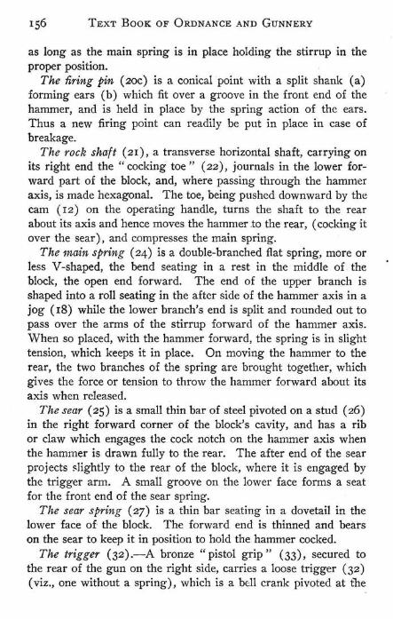
The firing pin (20C) is a conical point with a split shank (a) forming ears (b) which fit over a groove in the front end of the hammer, and is held in place by the spring action of the ears. Thus a new firing point can readily be put in place in case of breakage.
The rock shaft (21), a transverse horizontal shaft, carrying on its right end the "cocking toe" (22) , journals in the lower forward part of the block, and, where passing through the hammer axis, is made hexagonal. The toe, being pushed downward by the cam (12) on the operating handle, turns the shaft to the rear about its axis and hence moves the hammer to the rear, (cocking it over the sear), and compresses the main spring.
The main spring (24) is a double-branched flat spring, more or less V-shaped, the bend seating in a rest in the middle of the block, the open end forward. The end of the upper branch is shaped into a roll seating in the aftcr side of the hammer axis in a jog (18) while the lower branch's end is split and rounded out to pass over the arms of the stirrup forward of the hammer axis. When so placed, with the hammer forward, the spring is in slight tension, which keeps it in place. On moving the hammer to the rear, the two branches of the spring are brought together, which gives the force or tension to throw the hammer forward about its axis when released.
The sear (25) is a small thin bar of steel pivoted on a stud (26) in the right forward corner of the block's cavity, and has a rib or claw which engages the cock notch on the hammer axis when the hammer is drawn fully to the rear. The after end of the sear projects ~)ightly to the rear of the block, where it is engaged by the trigger arm. A small groove on the lower face forms a seat for the front end of the sear spring.
The sear spring (27) is a thin bar seating in a dovetail in the lower face of the block. The forward end is thinned and beats on the seat to keep it in position to hold the hammer cocked.
The trigger (32) .-A bronze "pistol grip" (33), secured to the rear of the gun on the right side, carries a loose trigger (32) (viz., one without a spring), which is a bdl crank pivoted at tne
HOTCHKISS BREECH MECHANISM 157
bend. The front end is in contact with the sear when the block is closed, while the rear end projects downward to form a finger grasp, which, if pulled to the rear, results in forcing down the sear to release the hammer, and thus fires the gun. On guns beyond No. 53 the pistol grip with loose trigger is replaced by a "trigger box" (38), secured to the gun by one long and one short screw, which contains a trigger pull (35) actuating a trigger lever (36) which bears on the sear. The lever has a flat spring (37), the rear end of which bears on the hub of the trigger, with a little boss that takes in a cut in the trigger when it is desired to turn up the latter for safety.
On recoil-mounted guns a lanyard is attached to the trigger, going through a hole in handle of pistol grip, if provided.
6. The Drill Hook for the Mark I 6-pounder and 3-pounder Hotchkiss Breech Mechanism is made of round wire, open at the top, the arms being bent to form hooks: It is designed to relieve the mechanism from strain when snapping the gun on drill; to protect the point from being injured by its shoulder striking heavily on the face plate, which tends to crystallize the meta] ; and to relieve the main spring from strain on ordinary occasions':" It hooks to the stirrup and the lower branch of the main spring, which is unshipped from the stirrnp. On" casting loose" for actual firing, the drill hook is removed and main spring hooked to stirrup. For subcalibre practice, however, the hook is left on, as the blow of the firing pin will be sufficiently strong.
7. The Action of the Mark I Breech Mechanism is as follows (suppose the gun fired and an empty case in the chamber) :
Opening.-The breech is opened by pulling the crank handles to the rear. The crank stud moves to the rear in the groove, the block descends by the cam action of the inclined part of the groove and by its own weight, until arrested by the stop bolt, when the bore of the gun is completely unmasked.
Cocking.-As the crank begins to move to the rear, its stud first passes over that part of the groove which is concentric "vith the crank stem; hence no motion results to the block. But during that period the cocking cam bears down the cocking toe, turns the rock shaft to the rear about its axis, and cocks the hammer, which is held cocked by the cock notch being engaged in the sear. The main spring is also compressed at the same time.

Page 157a follows Page 157 and faces Plate L Par. 2,
Chapter XI.
It has been added to this electronic edition to maintain proper pagination
when the work is printed on a duplexing printer.
In the original work, Plate I was a double plate "tipped in " to
the book so that all of its content would be visible. In this work, it
has been rotated 90deg so that it can be printed full size on a letter sized page.

....... , .. ~""'~~ .. ,. ~~! : : •••••.•
~... . ' . " -- '-.
. / /
I 2.7
[?J 10 34 ( 101 !
CHAPTER XI. PLATE I. Par. Z.
SR. MEC~ .
"'A 6 ' PoR. M"RK 1 GoUNS
V«««JL///t-.~ ~HIT. ~j§'@//#ff/f~~~' ..... ~.- _--~ ..... n_·--:i!:Sr~······." ....... -·,,"''l· .. ·h CRA.N~ HA.NDl.e C.A.T(.H
;1.1
16
[' : " ~.~~'" "'~'~:~".'.~.~.~' ~~.~ .. ~ .J~~i=-l ~ CXTRA.C.TOA.
E~-~m-- - .. u ...... mm
======21<2, -~"o ...... SCA" ~
_~_ neD
~~ I ..
€ @
9 20
CJ:r! 27 III f-: 1 ,.''', ..... "., ... T
~J;A'" ~"R.'H.G-
· ~ Ii ~ : · . • w • r · . f; · . O. ii 0
~ ~ ! e
Cf) .
~c
BR . MECH.
I · PDR. LIIiHTANDMAR~ I HI[AVY GUNS
l-PDR. AND 6-PDR. HOTCHKISS BREECH MECHANISM, MARK I.

158 TEXT BOOK OF ORDNANCE AND GUNNERY
E::ctraction.-As soon as the block begins to descend it moves slightly to the rear, due to the inclination of the guide ribs; hence the extractor moves slowly to the rear with great leverage and the case is started from its seat. When the block has descended sufficiently to unmask the bore, the abrupt change of the extractor groove to the rear gives a violent motion to the extractor which ejects the cartridge case.
Loading.-The cartridge is entered in the chamber until the rim of the case strikes the extractor's nib. On closing or raising the block, the beveled upper corner shoves home the cartridge and the extractor moves to the front.
Closing.-The breech is closed by moving the crank handles forward. When closed, the crank bears against the face of the gun tube, beyond the center of motion, and its stud supports the weight of the block. The face of the block now bears closely against the head of the cartridge.
Firing.-The breech being closed, the cocking cam and cocking toe are separated. By pulling the trigger (or lanyard attached to it), the trigger arm bears down on the rear projecting end of the sear and releases it from engagement with the hammer, which now flies forward under the action of the compressed main spring; the firing point, passing through the hole in the face plate, strikes the primer cap, which explodes and thus fires the gun.
8. The Hotchkiss Mark I Mechanism for I-pounders (Plate I) is in its interior parts the same as for the heavier guris except that there is no drill hook. There is but one crank handle instead of two; in the rock-shaft cocking toe is set a " fly" (22) on whid1 the cocking cam bears. The fly is used to prevent too great friction, since the sweep of the lever in cocking is very great. The trigger is held in a pistol grip, for the light I-pounder or non-recoil mounts. For heavy I-pounders, the trigger and trigger box are like that for the 6-pounder guns beyond No. 53.
9. The Hotchkiss Mark II 6-pounder Breech Mechanism (Plate II).-The bloclz (I), with all its moving parts as a 'whole. is interchangeable in the breech mortise of the Mark I gun. It is of the same general shape as the Mark I, but differs as follows: There is a vertical circular hole (6) open at the bottom, forming a pocket for the spiral main spring (25), on the left side, anel a

HOTCHKISS BREECH MECHANISl\1 159
similar, but smaller, pocket (7), on the right side, for the sear spring (32), both opening into the lower face of the block. Near the bottom of the former is an annular groove for the lip of the main spring lock (27). To the left of the block's central cavity is cut a groove into the main-spring pocket to permit the engagement of the main-spring sleeve on the hammer shaft. On the right of the plug's central cavity, a sear stop plug (16) guides the movement of the sear and is screwed into the plug, remaining as a permanent fixture. It also prevents the sear from coming off its pin, in the usual position. "The crank slot" (2) has an indentation on the upper forward end (in some of the blocks) in which the stud (I I) of the crank rests when the breech is closed.
The stop bolt (34) is not threaded, but is provided with a milled head on the outer end and a " spring lock" (35). This lock consists of a hollow sleeve, within which is a spiral spring, seating in a vertical hole in the head of the stop bolt, and an arm, in one with the sleeve, which lies in a longitudinal cut in the bolt. The inner end of the arm has a toe which engages in one of two annular grooves cut in the stop-bolt hole. The lock is retained on the bolt by a ring called" lock-bolt washer" (36). To operate the lock, " it is only necessary to press down on the sleeve, which moves the lock and will disengage the toe from the one of the grooves in the stop-bolt holes. These grooves are so arranged that when the toe is in the outer one the stop bolt is just clear of the block, while if engaged in the inner one the bolt enters the groove in the plug. This facilitates mounting or dismounting the block.
The crank handles (13) are held on the stem of the crank by means of a feather and" crank-handle lock" (r 5), as described in the Mark I mechanism.
The extractor is also the same as previously described except that the claw is detachable and made of tempered steel, to make it more elastic.
The hammer (17) has a rearward projecting lug (19) on its axis on the left side, which bears on the toe of the main-spring sleeve; this lug receives the push of the main spring to rotate the hammer about its axis for firing. The cock notch (20) is on the right side.
The firing point differs from the Mark I in being a conical point

160 TEXT BOOK OF ORDNANCE AND GUNNERY
with a split shank having two lugs. In entering, these lugs are placed opposite grooves in the hole in end of hammer, when by pushing it in, and then giving a partial turn with the dismounting tool, the lugs will engage behind the hammer head, being sprung apart by the spring of their arms.
The rocl~ shaft (22) projects through the block on the left side and is provided with a spring catch (24) to hold it on (necessary because there is no stirrup to hold the shaft in place as in Mark I) . This catch is a flat spring lying in a longitudinal slot on left end of the shaft; it has, on the outer end, a lug that slips over the edge of the hole in the block when the shaft is in place, preventing movement to the right.
The main spring (25) is a strong spiral spring which seats in its sleeve and is retained in the block by the "main-spring lock" (27) at the bottom.
The main-spring sleeve (26) is a hollow steel cylinder, partially closed at its upper end, provided with a toe on the lower end which projects forward to engage the lug on the hammer axis. Holding the main spring, it slips in a vertical pocket (6) in the plug, and is kept in place by the " spring lock."
The main-spring lock (27) is a bolt with head cut away on opposite sides to form lips, and a slot cut in its top for the dismounting tool. It is put in place by passing the shank of the bolt up inside the main spring and, with the dismounting tool engaged in the slot, pushirig downward to compress the spring, and then turning to the right or left a quarter turn so that the lips enter the annular groove· in the block. The pocket is slotted on opposite sides to form the annular groove which permits the lips of the lock to be entered or withdrawn, and thus a bayonet joint is formed.
The sear (28), of peculiar shape, is pivoted by a pin (3 I) on the side of the block as in Mark 1. There are two arms, one thick and heavy and provided with a shoulder to engage the cock notch on the hammer axis; the other, or firing arm (30), has in its extremity an eye for attachit:lg the firing lanyard, and thus acts alsG as a trigger.
The sear spring (32) is spiral and seats in its pocket (7) in the block, pushing down directly on the upper arm of the sear

HOTCHKISS BREECH MECHANISM I6r
to keep the latter engaged in the cock notch of the hammer when retracted.
10. DIFFERENCES BETWEEN MAHKS I AND II 6-POUNDER HOTCHKISS BREECH MECHANISMS.
--- --,----""---- - "--_ . --
Part. Mark 1.
Block .... As described.
Mark II.
Has two verticaJ holes in after part for main and sear spring"s.
Crank handle. Attached to crank stem by a Attached to crank stem by a feather and keep screw, taper feather and spring catch. pin or spring catch.
Hammer...... Has a stirrup and sear for a flat main spring.
Firingpoint.. Has roor projecting spring ears clasping end of hammer.
Rock shaft... Held to hammer shaft by a projector lip on the stirrup.
Main spring.. Double-branched flat spring, ends held on opposide side of hammer shaft.
Sear spring... Flat, free arm bearingon the sear.
Extractor .... In some, nib and body in single piece; others like Mark II.
Stop bolt. .... Screws into seat.
Trigger....... Ordinary bent lever held in pistol grip, one arm resting on free end of sear.
Has a cocking lug which bears on toe of main· spring sleeve.
Has spring split shank resting in rear of hammer.
Held in block by a spring catch 011 the lett end.
Spiral sprin ... which acts on lug of hammer through toe 011 slceve.
Spiral, bears on arm of sear when in place.
Nib separate from body to a~sist· in extraction by spriug temper and for strength.
Held in seat, and also when partly out, by a spring catch working in annular groove in stop-bolt hole.
No trigger. Firing lanyard hooks in arm of sear.
II. The Hotchkiss Mark II Mechanism for I-pounders (Plate II) employs a block similar to that for the 6-pounder gun except that the face plate is secured by a "lock button" instead of screws.
The crank handle and appendages differ somewhat from those of the Mark II 6-pounder. The cocking toe projects upward. The crank handle revolves freely on the stem, but in a boss on the outer side of the toe is a "runway" or slot (14a) in which plays a stud of the carrier (IS). The" carrier" takes the place of the fly in the rock-shaft toe of other models and is an extra appendage. It is kept from turning on the shaft by a feather,and from coming off by the carrier lock (16) (similar to the 6-pounder crank-

Page 161a
This page follows Page 161 and faces Plate III, Par. 13,
Chapter XI.
It was completely blank in the original work. v