Embed Size (px)
Citation preview
69-�
Report on Comments A2007 — Copyright, NFPA NFPA 69 Report of the Committee on
Explosion Protection Systems
Samuel A. Rodgers, ChairHoneywell, Inc., VA [U]
Luke S. Morrison, SecretaryProfessional Loss Control Inc., Canada [SE]
Joe R. Barton, Fountaintown, IN [SE] Kenneth L. Cashdollar, US Department of Health & Human Services, PA [RT] Michael Davies, PROTEGO (USA) Inc., SC [M] Alexi I. Dimopoulos, ExxonMobil Corporation, VA [U] Rep. American Petroleum Institute Robert J. Feldkamp, Nordson Corporation, OH [M] Larry D. Floyd, Ciba Specialty Chemicals Corporation, AL [U] () Joseph P. Gillis, Westboro, MA [SE] John E. Going, Fike Corporation, MO [M] Stanley S. Grossel, Process Safety & Design, Inc., NJ [SE] Dan A. Guaricci, ATEX Explosion Protection L.P., FL [M] Michael D. Hard, Hard Fire Suppression Systems, Inc., OH [IM] Rep. Fire Suppression Systems Association David D. Herrmann, E. I. DuPont de Nemours & Company, DE [U] David C. Kirby, Baker Engineering & Risk Consultants, WV [SE] Steven A. McCoy, National Starch & Chemical Company, IN [U] Rep. NFPA Industrial Fire Protection Section Peter J. McWilliams, Eastman Kodak Company, NY [U] () Robert W. Nelson, Pocasset, MA [I] Rep. Swiss Re, Global Asset Protection Services James O. Paavola, DTE Energy/Detroit Edison Company, MI [U] Stefan Penno, Rembe GmbH Safety & Control, Germany [M] Mitchel L. Rooker, BS&B Safety Systems, LLC, OK [M] Joseph A. Senecal, Kidde-Fenwal, Inc., MA [M] Bill Stevenson, CV Technology, Inc., FL [M] David R. Stottmann, Columbian TecTank, KS [M] Stephen M. Stuart, Marsh USA Inc., MI [I] Erdem A. Ural, Loss Prevention Science & Technologies, Inc., MA [SE] Bert von Rosen, Natural Resources Canada, Canada [E] Robert G. Zalosh, Firexplo, MA [SE]
Alternates
Geof Brazier, BS&B Safety Systems, LLC, OK [M] (Alt. to Mitchel L. Rooker) David G. Clark, E. I. DuPont de Nemours & Company, DE [U] (Alt. to David D. Herrmann) Martin P. Clouthier, Marsh Canada Ltd., Canada [I] (Alt. to Stephen M. Stuart) Ettore Contestabile, Natural Resources Canada, Canada [E] (Alt. to Bert von Rosen) Randal R. Davis, Kidde-Fenwal, Inc., MA [M] (Alt. to Joseph A. Senecal) Todd A. Dillon, Swiss Re, Global Asset Protection Services, OH [I] (Alt. to Robert W. Nelson) Kirk W. Humbrecht, Phoenix Fire Systems, Inc., IL [IM] (Alt. to Michael D. Hard) Edward L. Jones, Nordson Corporation, OH [M] (Alt. to Robert J. Feldkamp) Keith McGuire, Columbian TecTank, KS [M] (Alt. to David R. Stottmann) Richard F. Schwab, Honeywell, Inc., NJ [U] (Alt. to Samuel A. Rodgers) Jef Snoeys, Fike Corporation, Belgium [M] (Alt. to John E. Going)
Committee Scope: This Committee shall have primary responsibility for documents on explosion protection systems for all types of equipment and for buildings, except pressure venting devices designed to protect against overpressure of vessels such as those containing flammable liquids, liquefied gases, and compressed gases under fire exposure conditions, as now covered in existing NFPA standards.
This list represents the membership at the time the Committee was balloted on the text of this edition. Since that time, changes in the membership may have occurred. A key to classifications is found at the front of this book.
This portion of the Technical Committee Report of the Committee on Explosion Protection Systems is presented for adoption.
This Report on Comments was prepared by the Technical Committee on Explosion Protection Systems, and documents its action on the comments received on its Report on Proposals on NFPA 69, Standard on Explosion Prevention Systems, 2002 edition, as published in the Report on Proposals for the 2007 June Meeting.
This Report on Comments has been submitted to letter ballot of the Technical Committee on Explosion Protection Systems which consists of 28 voting members. The results of the balloting, after circulation of any negative votes, can be found in the report.
69-2
Report on Comments A2007 — Copyright, NFPA NFPA 69 ________________________________________________________________ 69-� Log #26 Final Action: Reject (Entire Document) ________________________________________________________________ Submitter: Samuel A. Rodgers, Honeywell, Inc. Comment on Proposal No: 69-2� Recommendation: Revise text to read as follows: Explanation to zones: Zone 0 Hazardous explosive Atmosphere continuously or long term available (> �000 h/a) Zone � Hazardous explosive Atmosphere occasionally available (�0 - �000 h/a) Zone 2 Hazardous explosive Atmosphere not or short term available (0 - �0 h/a) A Class I, Zone 0 location is a location in which (�) Ignitible concentrations of flammable gases or vapors are present continuously, or (2) Ignitible concentrations of flammable gases or vapors are present for long periods of time. A Class I, Zone 1 location is a location (1) In which ignitible concentrations of flammable gases or vapors are likely to exist under normal operating conditions; or (2) In which ignitible concentrations of flammable gases or vapors may exist frequently because of repair or maintenance operations or because of leakage; or (3) In which equipment is operated or processes are carried on, of such a nature that equipment breakdown or faulty operations could result in the release of ignitible concentrations of flammable gases or vapors and also cause simultaneous failure of electrical equipment in a mode to cause the electrical equipment to become a source of ignition; or (4) That is adjacent to a Class I, Zone 0 location from which ignitible concentrations of vapors could be communicated, unless communication is prevented by adequate positive pressure ventilation from a source of clean air and effective safeguards against ventilation failure are provided. A Class I, Zone 2 location is a location (1) In which ignitible concentrations of flammable gases or vapors are not likely to occur in normal operation and, if they do occur, will exist only for a short period; or (2) In which volatile flammable liquids, flammable gases, or flammable vapors are handled, processed, or used but in which the liquids, gases, or vapors normally are confined within closed containers of closed systems from which they can escape, only as a result of accidental rupture or breakdown of the containers or system, or as a result of the abnormal operation of the equipment with which the liquids or gases are handled, processed, or used; or (3) In which ignitible concentrations of flammable gases or vapors normally are prevented by positive mechanical ventilation but which may become hazardous as a result of failure or abnormal operation of the ventilation equipment; or (4) That is adjacent to a Class I, Zone 1 location, from which ignitible concentrations of flammable gases or vapors could be communicated, unless such communication is prevented by adequate positive-pressure ventilation from a source of clean air and effective safeguards against ventilation failure are provided. [70 505.5 (B)(�), B(2), B(3)] Substantiation: Reference A.�2.2.4.� Step 5. The definitions of Zones are not complete and do not address some particular issues included in NFPA 70. Replace current explanation of zones with extracted definitions of the zones without the fine print notes from NFPA 70 and show as extracted text. Committee Meeting Action: Reject Committee Statement: The Committee does not see the need to add this material which is completely documented within NFPA 70, National Electrical Code. The Committee has clarified aspects of this existing discussion within the standard as part of the action contained in Comment 69-56 (Log #CC2). Number Eligible to Vote: 28 Ballot Results: Affirmative: 22 Abstain: � Ballot Not Returned: 5 Cashdollar, K., Morrison, L., Penno, S., Stottmann, D., Ural, E. Explanation of Abstention: KIRBY, D.: I did not attend the meeting and do not feel comfortable voting on these issues. _______________________________________________________________ 69-2 Log #CC� Final Action: Accept (Entire Document) ________________________________________________________________ Submitter: Technical Committee on Explosion Protection Systems, Comment on Proposal No: 69-2 Recommendation: Editorial items from ROP text: Editorial comments in paragraphs �.3.� (�), (2) and (3) shown in parentheses in the ROP should be removed as shown: (�) Using the methods of Chapter 7 or 8 (ed. concentration, oxidant) to control the environment within the protected enclosure, such that a deflagration cannot occur, or (2) Using the methods of Chapter 9, ��, or �2(ed. passive, active) to isolate the identified potential ignition source from the protected enclosure, or (3) Using the methods of Chapters �0, �3, or �4 or NFPA 68 (ed. suppression, venting, containment, foam) to mitigate the effects of the
deflagration, such that the protected enclosure will not be uncontrollably breached. In �.3.�.3 (4) replace “Foam” with “Expanded Metal Mesh or Polymer Foam” to be consistent with the title for Chapter �4. In �0.4.2.2 change “design system” to “system design” to match the preceding paragraphs. In �4.3.2 change reference from paragraph �4.3.8 to �4.3.7. Substantiation: These are miscellaneous editorial items identified by the Committee from the ROP. It is intended that venting of deflagrations is an acceptable method, therefore reference to NFPA 68 should be included along with the other explosion prevention methods that mitigate the effects based upon NFPA 69 requirements. Committee Meeting Action: Accept Number Eligible to Vote: 28 Ballot Results: Affirmative: 22 Abstain: � Ballot Not Returned: 5 Cashdollar, K., Morrison, L., Penno, S., Stottmann, D., Ural, E. Explanation of Abstention: KIRBY, D.: I did not attend the meeting and do not feel comfortable voting on these issues. _______________________________________________________________ 69-3 Log #53 Final Action: Accept in Principle (1.2.3) ________________________________________________________________ Submitter: David D. Herrmann, E. I. DuPont de Nemours & Company Comment on Proposal No: 69-� Recommendation: Revise text to read as follows: (2) Third party inspection and approval of active and passive isolation devices, spark detection systems and suppression systems. Substantiation: While there is a value in validation of the design basis for oxidant control or concentration control systems, there is currently no wording in those sections of the standard that requires such a validation, nor is the wording in the general section sufficient to describe that intent. The intent to validate the design basis for oxidant control or concentration control systems may also be covered in the intent of (6) design documentation or (3) management of change. Simply changing third party inspection to second party inspection also does nothing to clarify these issues. I believe that the sole reason for (2) as written is that flame arresters, isolation devices, suppression systems, and spark detection systems are typically third party inspected and approved. The need for third party inspection is appropriately further clarified in these subsections. Saying that the third party inspection and approval applies to design basis is confusing (even if we change the wording to second party) since it has been explained in the standard that it applies to systems that undergo a rigorous evaluation of the design methodology. The design methodology is well described in the standard for oxidant or flammable concentration control systems, and should not require third (or second) party review. In addition, third party inspection has never been consistently utilized for containment, and the standard requires regular vessel inspection (no third party specified) and inspection after events. The use of API-5�0 is an acceptable practice in non code states and it has similar requirements to the NBIC (National Board of Boiler and Pressure Vessel Inspectors) repair code. The NBIC, however, requires an outside inspector oversee the repair work whereas API-5�0 does not. We always inspect our vessels, but do not involve a third party unless required by local codes since we have qualified inspectors within the company. The need for inspection is spelled out in the containment chapter. We do not want the general statement as currently written in (2) to be confused with inspection for vessel containment. Committee Meeting Action: Accept in Principle Revise text to read as follows: (2) Third party inspection and approval of protection systems by an internationally recognized testing laboratory for the function intended, as specified in Chapters 7 through �4. Committee Statement: The intent of the submitter has been satisfied and the Committee has combined additional revision text on inspection and approvals from Comment 69-4 (Log #29) on this same subject. Number Eligible to Vote: 28 Ballot Results: Affirmative: �9 Negative: 3 Abstain: � Ballot Not Returned: 5 Cashdollar, K., Morrison, L., Penno, S., Stottmann, D., Ural, E. Explanation of Negative: FELDKAMP, R.: I agree with the explanations of B. Stevenson and R. Zalosh. STEVENSON, B.: The submitter’s proposed language makes sense, but the committee change does not. Whereas there is a formal recognition and definition under OSHA for Nationally Recognized Testing Laboratory (NRTL), there is not an equivalent for “internationally recognized testing laboratory.” Moreover, there is no agency with authority to create one. To require third party inspection from an entity that does not exist is not a good idea. ZALOSH, R.: Since most internationally recognized testing laboratories do not conduct inspections of installed protection systems, I don’t see how this requirement can be implemented in practice. Explanation of Abstention: KIRBY, D.: I did not attend the meeting and do not feel comfortable voting on these issues.
69-3
Report on Comments A2007 — Copyright, NFPA NFPA 69 _______________________________________________________________ 69-4 Log #29 Final Action: Accept in Principle in Part (1.2.3(2), 1.2.3(7)) ________________________________________________________________ Submitter: Dan A. Guaricci, ATEX Explosion Protection L.P. Comment on Proposal No: 69-� Recommendation: Modify �.2.3(2) as below and add �.2.3(7): �.2.3 (2) Third Party Inspection and Approvals for the function intended by an internationally recognized testing laboratory. �.2.3 (7) If required by the Authority Having Jurisdiction, the systems shall have approved safety integrity level approvals. Substantiation: Reference �.2.3(2) and �.2.3(7). Approvals of �.2.3 (2) must be required for the function intended, otherwise a safety product can have FM approvals for the integrity of their junction boxes which would technically qualify as an approval by a third party. The ISA SIL approval levels, while not applicable to all, need to be required for those companies that believe them to be significantly important. By adding this statement to the standard it is required for companies that demand this level of safety integrity while not required for those companies that do not need this level of system integrity. This standard is a future standard and not a past standard so it needs to reflect the requirements of the future in a more positive manner for concerned users. Committee Meeting Action: Accept in Principle in Part See Committee Action on 69-3 (Log #53) for the recommended revision to �.2.3 (2). The Committee rejected the recommendation to add the new text to �.2.3 (7). Committee Statement: The Committee satisfied the intent of the submitter on the first recommendation with the action taken in Comment 69-3 (Log #53). The Committee addresses options for SIL determination in Annex material within the standard and does not require system manufacturers to evaluate SIL at this time. Number Eligible to Vote: 28 Ballot Results: Affirmative: 20 Negative: 2 Abstain: � Ballot Not Returned: 5 Cashdollar, K., Morrison, L., Penno, S., Stottmann, D., Ural, E. Explanation of Negative: FELDKAMP, R.: I agree with the explanation of R. Zalosh. ZALOSH, R.: See my Explanation of Negative Vote on Comment 69-3 (Log #53). Explanation of Abstention: KIRBY, D.: I did not attend the meeting and do not feel comfortable voting on these issues. _______________________________________________________________ 69-5 Log #3 Final Action: Accept in Principle (1.3.1) ________________________________________________________________ Submitter: Bill Stevenson, CV Technology, Inc. / Rep. TC Member Comment on Proposal No: 69-2 Recommendation: Modify current �.3.�(3) by adding “or” at the end and add a new �.3.�(4). 3) Using methods of Chapters �0, �3, or �4 to mitigate the effects of the deflagration, such that the protected enclosure will not be uncontrollably breached, or 4) Using the performance-based methods of Chapters 4 and 5. Substantiation: This clarifies to the user that there are two approaches that can be followed to provide protection and directs the user to the appropriate chapters to determine the one most suitable for the circumstances. Committee Meeting Action: Accept in Principle See Committee Action on 69-6 (Log #28). Committee Statement: See Committee Action and Statement on 69-6 (Log #28). The action in the referenced comment accomplishes the intent of the submitter. Number Eligible to Vote: 28 Ballot Results: Affirmative: 22 Abstain: � Ballot Not Returned: 5 Cashdollar, K., Morrison, L., Penno, S., Stottmann, D., Ural, E. Explanation of Abstention: KIRBY, D.: I did not attend the meeting and do not feel comfortable voting on these issues. _______________________________________________________________ 69-6 Log #28 Final Action: Accept in Principle (1.3.1) ________________________________________________________________ Submitter: Dan A. Guaricci, ATEX Explosion Protection L.P. Comment on Proposal No: 69-2 Recommendation: Revise text to read as follows: �.3.� When desired by the owner/operator, or required by the authority having jurisdiction, or when required by other standards, explosion prevention shall be achieved by one or more of the following methods as required to mitigate the damage and or prevent the propagation of the ignition source and/or deflagration: (�) Using the methods of Chapter 7 or 8 (ed. concentration, oxidant) to control the environment within the protected enclosure, such that a deflagration cannot occur, and/or (2) Using the methods of Chapter 9, ��, or �2(ed. passive, active) to isolate
the identified potential ignition source from the protected enclosure to prevent the propagation of a deflagration to connected vessels via ductwork or prevent the propagation of an ignition source, and/or (3) Using the methods of Chapters �0, �3, or �4 (ed. suppression, venting, containment, foam) to mitigate the effects of the deflagration, such that the protected enclosure will not be uncontrollably breached. Substantiation: Reference �.3.�. Isolation methods prevent the propagation of a deflagration, they have no effect on some ignition sources and some isolation methods have no ability to stop deflagrations but can isolate explosion ignition sources so they can not be used in place of one another as inferred. Committee Meeting Action: Accept in Principle Revise text to read as follows: �.3.� When desired by the owner/operator, or required by the authority having jurisdiction, or when required by other standards, explosion prevention shall be achieved by one or more of the following methods as required to mitigate the damage, prevent the transport of the ignition source, and propagation of the deflagration: (�) Using the methods of Chapter 7 or 8 (ed. concentration, oxidant) to control the environment within the protected enclosure, such that a deflagration cannot occur, or (2) Using the methods of Chapter 9, ��, or �2 (ed. passive, active) to isolate the identified potential ignition source from the protected enclosure to prevent the propagation of a deflagration to connected vessels or prevent the transport of an ignition source, or (3) Using the methods of Chapters �0, �3, or �4 or NFPA 68 (ed. suppression, venting, containment, foam) to mitigate the effects of the deflagration, such that the protected enclosure will not be uncontrollably breached. �.3.�.� It shall be permitted to use the methods of Chapters 4 and 5 in lieu of the methods in Chapters 7 through �4 explosion protection in Chapters 7, 8, 9, �0, ��, �2, �3, or �4 in combination. Committee Statement: Editorial corrections to more properly identify the transport of an ignition source as opposed to the propagation of an ignition source. The revision to paragraph �.3.�.� combined existing requirements with the recommendation from Comment 69-5 (Log #3). Number Eligible to Vote: 28 Ballot Results: Affirmative: 2� Negative: � Abstain: � Ballot Not Returned: 5 Cashdollar, K., Morrison, L., Penno, S., Stottmann, D., Ural, E. Explanation of Negative: GUARICCI, D.: To indicate that the types of systems in the indicated chapters deal in any way shape or form with the impending threat in the same way is to mislead the reader. Methods in Chapter 9 reduce the potential of a deflagration but do not deal with the deflagration. Methods in Chapters �� and �2 are designed to isolate an events propagation and deal with the deflagration hazard. If a system in Chapter 9 does not function methods of venting and suppression apply. If a system in Chapters �� and �2 doesn’t function then protection methods of venting and/or suppression may not function even if they are in place. The wood industry is a definition of the misapplication of spark detection to deal with a deflagration. They have more explosions than any other industry and use more spark detection that any other industry to deal alone with the deflagration hazard. The statement in �.3.�(2) leads the reader to believe they provide the same function when they do not. Explanation of Abstention: KIRBY, D.: I did not attend the meeting and do not feel comfortable voting on these issues.
_______________________________________________________________ 69-8 Log #30 Final Action: Reject (1.3.1.2) ________________________________________________________________ Submitter: Dan A. Guaricci, ATEX Explosion Protection L.P. Comment on Proposal No: 69-2 Recommendation: Revise text as follows: �.3.�.2 This standard shall apply to methods for pre -deflagration detection or control of ignition. Substantiation: Reference �.3.�.2 This standard deals with deflagrations after ignition. Committee Meeting Action: Reject Committee Statement: The standard does properly deal with pre-deflagration detection. Number Eligible to Vote: 28 Ballot Results: Affirmative: 22 Abstain: � Ballot Not Returned: 5 Cashdollar, K., Morrison, L., Penno, S., Stottmann, D., Ural, E. Explanation of Abstention: KIRBY, D.: I did not attend the meeting and do not feel comfortable voting on these issues.
Sequence 69-7 was not used
69-4
Report on Comments A2007 — Copyright, NFPA NFPA 69 _______________________________________________________________ 69-9 Log #3� Final Action: Accept in Principle (1.3.1.3) ________________________________________________________________ Submitter: Dan A. Guaricci, ATEX Explosion Protection L.P. Comment on Proposal No: 69-2 Recommendation: Revise text as follows: �.3.�.3* When another standard requires explosion prevention or control in accordance with NFPA 69 for an enclosure and that enclosure is interconnected to other enclosures by a line containing combustible dust, gas, mist, or hybrid mixtures that could transmit flame or pressure from the original enclosure, explosion prevention or control shall be provided for interconnected enclosures by one of the following: �) Deflagration isolation as shown in Section 9.2 or �0.2 2) Explosion venting of the connecting pipe and the interconnected enclosures within the limitations specified in NFPA 68 32) Containment as discussed in Chapter �3 4) Foam as discussed in Chapter �4 Substantiation: Reference �.3.�.3. Venting of ductwork is not a reliable means to isolate an explosion propagation. Eliminate section �.3.�.3(2) as explosion venting does not stop the propagation of an event. Eliminate �.3.�.3(4) as foam is not quick enough to isolate a deflagration. Committee Meeting Action: Accept in Principle Revise text as follows: �.3.�.3* When another standard requires explosion prevention or control in accordance with NFPA 69 for an enclosure and that enclosure is interconnected to other enclosures by a line containing combustible dust, gas, mist, or hybrid mixtures that could transmit flame or pressure from the original enclosure, explosion prevention or control shall be provided for interconnected enclosures by one of the following: �) Deflagration isolation as discussed shown in Chapters �� and �2 Section 9.2 or �0.2 2) Explosion venting of the connecting pipe and the interconnected enclosures within the limitations specified in NFPA 68, Section 8.�0. 3) Containment as discussed in Chapter �3 4) Expanded metal mesh or polymer Ffoam as discussed in Chapter �4. Committee Statement: The Committee recognized the necessary limitation to the applicable parts of NFPA 68, which satisfies the submitter’s intent and recommendation. The Committee also modified item (4) by making the statement consistent with the title of Chapter �4. Number Eligible to Vote: 28 Ballot Results: Affirmative: 2� Negative: � Abstain: � Ballot Not Returned: 5 Cashdollar, K., Morrison, L., Penno, S., Stottmann, D., Ural, E. Explanation of Negative: GUARICCI, D.: �.3.�.3 To tell a reader that an acceptable method to stop the propagation of a deflagration is through venting when applied per NFPA 68 when 68 indicates that venting will not stop the propagation of an event is misleading and confusing to the reader. Nowhere in 69 is venting applied to stop the propagation of an explosion. Explanation of Abstention: KIRBY, D.: I did not attend the meeting and do not feel comfortable voting on these issues. _______________________________________________________________ 69-�0 Log #32 Final Action: Reject (1.3.1.4) ________________________________________________________________ Submitter: Dan A. Guaricci, ATEX Explosion Protection L.P. Comment on Proposal No: 69-2 Recommendation: Revise text as follows: �.3.�.4 It shall be permitted to eliminate deflagration isolation protection for interconnected enclosures based upon a documented risk analysis acceptable to the authority having jurisdiction, unless isolation protection is specifically required for such enclosure by other standards where it indicates the propagation of the explosion would not have an adverse effect on the protection in a connected vessel. Substantiation: Reference �.3.�.4. As �.3.�.3 already requires protection only when a propagation is possible, the risk analysis of �.3.�.4 would only evaluate the acceptability of the anticipated effect on the connected vessel. Committee Meeting Action: Reject Committee Statement: The Committee believes that the current text in the standard adequately addresses this issue. Number Eligible to Vote: 28 Ballot Results: Affirmative: 22 Abstain: � Ballot Not Returned: 5 Cashdollar, K., Morrison, L., Penno, S., Stottmann, D., Ural, E. Explanation of Abstention: KIRBY, D.: I did not attend the meeting and do not feel comfortable voting on these issues.
_______________________________________________________________ 69-�� Log #33 Final Action: Accept in Principle (Chapter 3) ________________________________________________________________ Submitter: Dan A. Guaricci, ATEX Explosion Protection L.P. Comment on Proposal No: 69-3 Recommendation: Revise text as follows: Reduced Pressure ( Pred ). (NFPA 68, 2002 ed.) The maximum calculated pressure developed in a vented enclosure during a vented deflagration. Substantiation: Reference Pred definition. It is not clear whether Pred is an actual or calculated maximum pressure. Add “calculated” to the definition. Committee Meeting Action: Accept in Principle Add the following new Annex text: A.3.3 Reduced Pressure. Pred is the maximum reduced pressure that a deflagration will produce when a protection system such as venting, suppression, or heat removal functions. Pred can be calculated or measured during testing. The calculated value will normally be higher than what is actually achieved. Committee Statement: Annex text has been added to explain how reduced pressure is used in this document. Number Eligible to Vote: 28 Ballot Results: Affirmative: 2� Negative: � Abstain: � Ballot Not Returned: 5 Cashdollar, K., Morrison, L., Penno, S., Stottmann, D., Ural, E. Explanation of Negative: SENECAL, J.: Redefining PRED in the proposed manner is wrong. PRED is the actual maximum pressure achieved in an enclosure during a deflagration when venting or suppression is used to mitigate explosion pressure. A calculation of PRED, using methods such as given in NFPA 68, is only an estimate of PRED. Explanation of Abstention: KIRBY, D.: I did not attend the meeting and do not feel comfortable voting on these issues. _______________________________________________________________ 69-�2 Log #�� Final Action: Accept in Principle in Part (3.p.q Limiting Oxygen Concentration (LOC), Limiting Oxygen (Oxidant) Concentration (LOC) (New) and 5.2.2 ) ________________________________________________________________ Submitter: Erdem A. Ural, Loss Prevention Science & Technologies, Inc. Comment on Proposal No: 69-3 Recommendation: Revise text to read as follows: Limiting Oxidant Concentration (LOC). (preferred) NFPA 86, 2003 ed. The concentration of oxidant below which a deflagration cannot occur.. 3.p.q* Limiting Oxygen (Oxidant) Concentration (LOC). The concentration of oxidant below which a deflagration cannot occur at any fuel concentration, and at the worst case process temperature and pressure. For gases and vapors LOC shall be based on test data obtained in accordance with ASTM E 2079. For dusts, an appropriate test apparatus shall be used in conjunction with a strong ignition source that has nominal energy of at least 2.5 kJ. A.3.p.q Limiting Oxygen (Oxidant) Concentration (LOC). Materials other than oxygen can act as oxidants. Preliminary results of the ASTM E 2079 round robin tests revealed that the limiting oxygen concentration (LOC) data which were obtained using different test methods and listed in a majority of reference publications are non-conservative. The old Bureau of Mines data were obtained mostly in a 5 cm diameter flammability tube. This diameter may be too small to mitigate the flame quenching influence, thereby impeding accurate determination of the LOC of most fuels. The 4 L minimum volume specified in ASTM E 2079 would correspond to a diameter of at least 20 cm. As a result, some LOC values determined using this standard are approximately � vol.% lower than the previous values measured in the flammability tube, and a few are even up to 2% lower. The lower LOC values obtained in larger chambers are more appropriate for use in fire and explosion hazard assessment studies. A data comparison can be found in Table A.3.p.q. See Table A.3.p.q on the next page Generally, LOC decreases as the pressure or temperature prior to ignition increases. Best practice is to test the LOC at the appropriate temperature and pressure. Deviations from the test fuel composition and temperature may possibly be accounted for by using appropriate techniques. [NOTE TO NFPA STAFF: THE NUMBERING BELOW REFERS TO 2002 EDITION PARAGRAPH NUMBERS] 5.2.2 Limiting Oxidant Concentrations (LOC). 5.2.2.1* Table C.�(a), Table C.�(b), and Table C.�(c) shall be permitted to be used as a basis for determining limiting oxidant concentrations of flammable gases or suspensions of combustible dusts. 5.2.2.1.1 For gases and vapors, if the LOC values according to ASTM E 2079 are available, then these shall be used without adjustment. 5.2.2.1.2 For gases and vapors, if the LOC values according to ASTM E 2079 are not available, then the LOC values obtained in flammability tubes shall be used after adjustment by subtracting 2% oxidant. 5.2.2.2 For fuel/inert/oxidant combinations not listed in Table C.�(a), Table C.�(b), and Table C.�(c) or for situations when the process conditions differ from the conditions under which the existing data were obtained, the test methods described in ASTM E 2079, Standard Test Method for Limiting
69-5
Report on Comments A2007 — Copyright, NFPA NFPA 69
Oxygen (Oxidant) Concentration for Gases and Vapors, shall be permitted to be used. 5.2.2.3 The extent of oxidant reduction shall be determined by testing where conditions vary significantly from the test conditions under which the data were obtained. Table C.�(a) Limiting Oxidant Concentrations for Flammable Gases When Using Nitrogen or Carbon Dioxide as Diluents – SEE REFERENCES AT THE END OF THE TABLE FOR THE DESIGNATION OF LFL DATA OBTAINED IN FLAMMABILITY TUBES AND HENCE MUST BE CORRECTED BY SUBTRACTING 2% (See Paragraph A 3.p.q). REVISE EXISTING TABLE ENTRIES AS FOLLOWS ADD NEW (UNPUBLISHED) PRL DATA ENTRIES. COMMITTEE TO DECIDE WHETHER TO BREAK THE TABLE TO TWO: OLD VERSUS NEW. CREATE A NEW COLUMN FOR TEST TEMPERATURE DATA Notes: �. See 5.7.2 for the required oxygen level in equipment. 2. Data were determined by laboratory experiment conducted at atmospheric temperature and pressure. Vapor-air-inert gas samples were placed in explosion tubes and ignited by electric spark or pilot flame. References for Table C.�(a). �. J. F. Coward and G. W. Jones (�952). SUBTRACT 2% 2. G. W. Jones, M. G. Zabetakis, J. K. Richmond, G. S. Scott, and A. L. Furno (�954). SUBTRACT 2% 3. J. M. Kuchta, A. L. Furno, A. Bartkowiak, and G. H. Martindill (�968). SUBTRACT 2% 4. M. G. Zabetakis (�965). SUBTRACT 2% 5. M. G. Zabetakis and B. H. Rosen (�957). SUBTRACT 2% 6. Unpublished data, U.S. Bureau of Mines. SUBTRACT 2% 7. Unpublished data, Dow Chemical Co. 8. U.S. Bureau of Mines. SUBTRACT 2% 9. L.G. Britton (2002). �0. Unpublished, Dow Chemical Co. 2002. Substantiation: The newly modified definition of LOC does not mention the test method used for determination and results in confusion and potential reduced safety as the testing method is being revised. Data for gases currently included in the standard is based largely on Bureau of Mines flammability tube tests and newer methods are resulting in significantly reduced LOC values. In addition, while it is known that LOC is affected by temperature and pressure, the definition or text does not address the reductions in LOC as these parameters are increased. The use of Table C.�(b) should be discouraged because: (�) data were obtained using a relatively weak (compared to flame ignition source), and (2) the particle size distribution of the test samples are not provided. Furthermore, in light of the variation in test methods and the lack of available data by the newer method, a conservative means to estimate LOC values from existing flammability tube results should be provided in Section 5.2.2. Add two sections, 5.2.2.�.� and 5.2.2.�.2 to address LOC measurements by the old flammability tube and the newer method. Committee Meeting Action: Accept in Principle in Part Revise text to read as follows: Do not use the submitter’s proposed definition for LOC; use the one shown below instead: 3.3.25* Limiting Oxidant Concentration (LOC). The concentration of oxidant in a fuel-oxidant-diluent mixture below which a deflagration cannot occur under specified conditions.
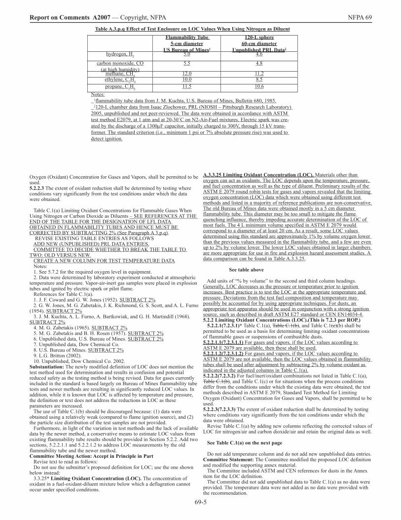
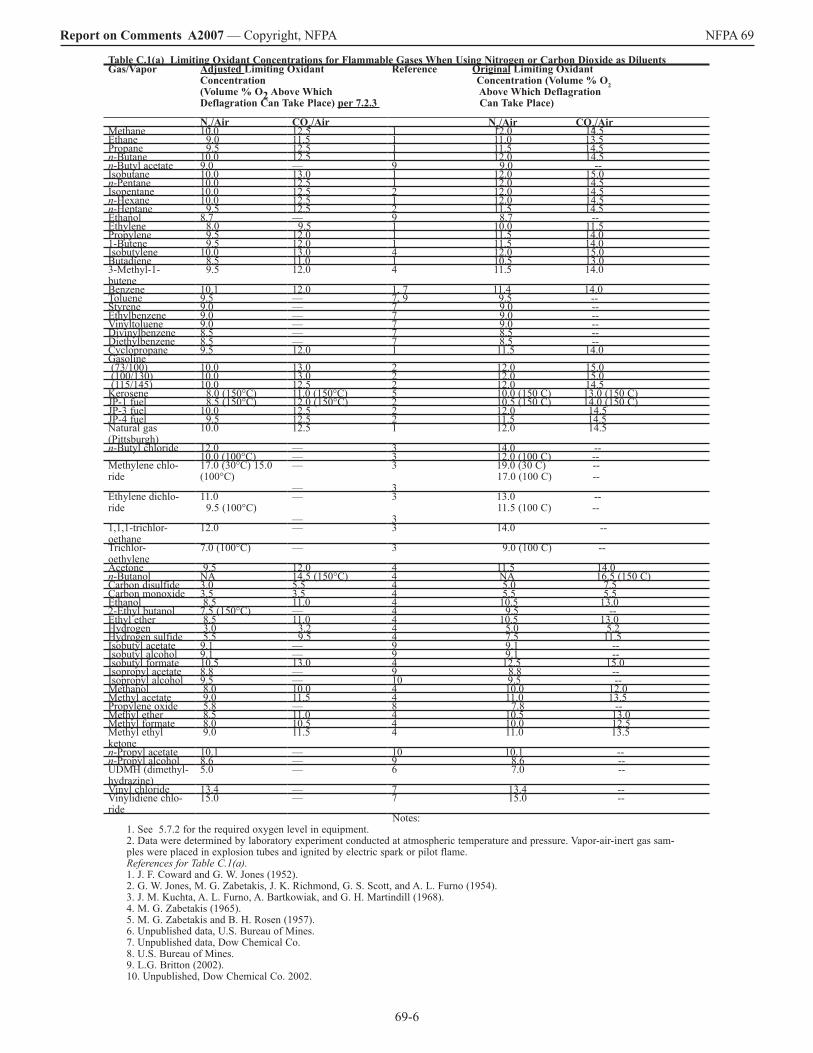
A.3.3.25 Limiting Oxidant Concentration (LOC). Materials other than oxygen can act as oxidants. The LOC depends upon the temperature, pressure, and fuel concentration as well as the type of diluent. Preliminary results of the ASTM E 2079 round robin tests for gases and vapors revealed that the limiting oxygen concentration (LOC) data which were obtained using different test methods and listed in a majority of reference publications are non-conservative. The old Bureau of Mines data were obtained mostly in a 5 cm diameter flammability tube. This diameter may be too small to mitigate the flame quenching influence, thereby impeding accurate determination of the LOC of most fuels. The 4 L minimum volume specified in ASTM E 2079 would correspond to a diameter of at least 20 cm. As a result, some LOC values determined using this standard are approximately �% by volume oxygen lower than the previous values measured in the flammability tube, and a few are even up to 2% by volume lower. The lower LOC values obtained in larger chambers are more appropriate for use in fire and explosion hazard assessment studies. A data comparison can be found in Table A.3.3.25. See table above Add units of “% by volume” to the second and third column headings. Generally, LOC decreases as the pressure or temperature prior to ignition increases. Best practice is to test the LOC at the appropriate temperature and pressure. Deviations from the test fuel composition and temperature may possibly be accounted for by using appropriate techniques. For dusts, an appropriate test apparatus should be used in conjunction with a strong ignition source, such as described in draft ASTM E27 standard or CEN EN�4034-4. 5.2.2 Limiting Oxidant Concentrations (LOC).(This is 7.2.3 per ROP.) 5.2.2.1(7.2.3.1)* Table C.�(a), Table C.�(b), and Table C.�(c)(b) shall be permitted to be used as a basis for determining limiting oxidant concentrations of flammable gases or suspensions of combustible dusts. 5.2.2.1.1(7.2.3.1.1) For gases and vapors, if the LOC values according to ASTM E 2079 are available, then these shall be used. 5.2.2.1.2(7.2.3.1.2) For gases and vapors, if the LOC values according to ASTM E 2079 are not available, then the LOC values obtained in flammability tubes shall be used after adjustment by subtracting 2% by volume oxidant as indicated in the adjusted columns in Table C.�(a). 5.2.2.2(7.2.3.2) For fuel/inert/oxidant combinations not listed in Table C.�(a), Table C.�(b), and Table C.�(c) or for situations when the process conditions differ from the conditions under which the existing data were obtained, the test methods described in ASTM E 2079, Standard Test Method for Limiting Oxygen (Oxidant) Concentration for Gases and Vapors, shall be permitted to be used. 5.2.2.3(7.2.3.3) The extent of oxidant reduction shall be determined by testing where conditions vary significantly from the test conditions under which the data were obtained. Revise Table C.�(a) by adding new columns reflecting the corrected values of LOC for nitrogen/air and carbon dioxide/air and retain the original data as well. See Table C.1(a) on the next page Do not add temperature column and do not add new unpublished data entries. Committee Statement: The Committee modified the proposed LOC definition and modified the supporting annex material. The Committee included ASTM and CEN references for dusts in the Annex item for the LOC definition. The Committee did not add unpublished data to Table C.�(a) as no data were provided. The temperature data were not added as no data were provided with the recommendation.
Table A.3.p.q Effect of Test Enclosure on LOC Values When Using Nitrogen as DiluentFlammability Tube
5-cm diameterUS Bureau of Mines1
120-L sphere60-cm diameter
Unpublished PRL Data2
hydrogen, H2 5.0 4.6
carbon monoxide, CO(at high humidity)
5.5 4.8
methane, CH4 �2.0 ��.2ethylene, C2H4 �0.0 8.5propane, C3H8 ��.5 �0.6
Notes: �flammability tube data from J. M. Kuchta, U.S. Bureau of Mines, Bulletin 680, �985. 2�20-L chamber data from Isaac Zlochower, PRL (NIOSH – Pittsburgh Research Laboratory) 2005, unpublished and not peer-reviewed. The data were obtained in accordance with ASTM test method E2079, at 1 atm and at 20-30˚C on N2-Air-Fuel mixtures. Electric spark was cre-ated by the discharge of a �300µF capacitor, initially charged to 300V, through �5 kV trans-former. The standard criterion (i.e., minimum � psi or 7% absolute pressure rise) was used to detect ignition.
69-6
Report on Comments A2007 — Copyright, NFPA NFPA 69
Table C.1(a) Limiting Oxidant Concentrations for Flammable Gases When Using Nitrogen or Carbon Dioxide as DiluentsGas/Vapor Adjusted Limiting Oxidant
Concentration (Volume % O2 Above Which Deflagration Can Take Place) per 7.2.3
Reference Original Limiting Oxidant Concentration (Volume % O2 Above Which Deflagration Can Take Place)
N2/Air CO2/Air N2/Air CO2/AirMethane �0.0 �2.5 � �2.0 �4.5Ethane 9.0 ��.5 � ��.0 �3.5Propane 9.5 �2.5 � ��.5 �4.5n-Butane �0.0 �2.5 � �2.0 �4.5n-Butyl acetate 9.0 — 9 9.0 --Isobutane �0.0 �3.0 � �2.0 �5.0n-Pentane �0.0 �2.5 � �2.0 �4.5Isopentane �0.0 �2.5 2 �2.0 �4.5n-Hexane �0.0 �2.5 � �2.0 �4.5n-Heptane 9.5 �2.5 2 ��.5 �4.5Ethanol 8.7 — 9 8.7 --Ethylene 8.0 9.5 � �0.0 ��.5Propylene 9.5 �2.0 � ��.5 �4.0�-Butene 9.5 �2.0 � ��.5 �4.0Isobutylene �0.0 �3.0 4 �2.0 �5.0Butadiene 8.5 ��.0 � �0.5 �3.03-Methyl-�- butene
9.5 �2.0 4 ��.5 �4.0
Benzene �0.� �2.0 �, 7 ��.4 �4.0Toluene 9.5 — 7, 9 9.5 --Styrene 9.0 — 7 9.0 --Ethylbenzene 9.0 — 7 9.0 --Vinyltoluene 9.0 — 7 9.0 --Divinylbenzene 8.5 — 7 8.5 --Diethylbenzene 8.5 — 7 8.5 --Cyclopropane 9.5 �2.0 � ��.5 �4.0Gasoline (73/�00) �0.0 �3.0 2 �2.0 �5.0 (�00/�30) �0.0 �3.0 2 �2.0 �5.0 (��5/�45) �0.0 �2.5 2 �2.0 �4.5Kerosene 8.0 (�50°C) ��.0 (�50°C) 5 �0.0 (�50 C) �3.0 (�50 C)JP-� fuel 8.5 (�50°C) �2.0 (�50°C) 2 �0.5 (�50 C) �4.0 (�50 C)JP-3 fuel �0.0 �2.5 2 �2.0 �4.5JP-4 fuel 9.5 �2.5 2 ��.5 �4.5Natural gas (Pittsburgh)
�0.0 �2.5 � �2.0 �4.5
n-Butyl chloride �2.0 — 3 �4.0 --�0.0 (�00°C) — 3 �2.0 (�00 C) --
Methylene chlo-ride
�7.0 (30°C) �5.0 (�00°C)
— —
3 �9.0 (30 C) -- �7.0 (�00 C) -- 3
Ethylene dichlo-ride
��.0 9.5 (�00°C)
— —
3 �3.0 -- ��.5 (�00 C) -- 3
�,�,�-trichlor- oethane
�2.0 — 3 �4.0 --
Trichlor- oethylene
7.0 (�00°C) — 3 9.0 (�00 C) --
Acetone 9.5 �2.0 4 ��.5 �4.0n-Butanol NA �4.5 (�50°C) 4 NA �6.5 (�50 C)Carbon disulfide 3.0 5.5 4 5.0 7.5Carbon monoxide 3.5 3.5 4 5.5 5.5Ethanol 8.5 ��.0 4 �0.5 �3.02-Ethyl butanol 7.5 (�50°C) — 4 9.5 --Ethyl ether 8.5 ��.0 4 �0.5 �3.0Hydrogen 3.0 3.2 4 5.0 5.2Hydrogen sulfide 5.5 9.5 4 7.5 ��.5Isobutyl acetate 9.� — 9 9.� --Isobutyl alcohol 9.� — 9 9.� --Isobutyl formate �0.5 �3.0 4 �2.5 �5.0Isopropyl acetate 8.8 — 9 8.8 --Isopropyl alcohol 9.5 — �0 9.5 --Methanol 8.0 �0.0 4 �0.0 �2.0Methyl acetate 9.0 ��.5 4 ��.0 �3.5Propylene oxide 5.8 — 8 7.8 --Methyl ether 8.5 ��.0 4 �0.5 �3.0Methyl formate 8.0 �0.5 4 �0.0 �2.5Methyl ethyl ketone
9.0 ��.5 4 ��.0 �3.5
n-Propyl acetate �0.� — �0 �0.� --n-Propyl alcohol 8.6 — 9 8.6 --UDMH (dimethyl- hydrazine)
5.0 — 6 7.0 --
Vinyl chloride �3.4 — 7 �3.4 --Vinylidiene chlo-ride
�5.0 — 7 �5.0 --
Notes:�. See 5.7.2 for the required oxygen level in equipment.2. Data were determined by laboratory experiment conducted at atmospheric temperature and pressure. Vapor-air-inert gas sam-ples were placed in explosion tubes and ignited by electric spark or pilot flame.References for Table C.1(a).�. J. F. Coward and G. W. Jones (�952).2. G. W. Jones, M. G. Zabetakis, J. K. Richmond, G. S. Scott, and A. L. Furno (�954).3. J. M. Kuchta, A. L. Furno, A. Bartkowiak, and G. H. Martindill (�968).4. M. G. Zabetakis (�965).5. M. G. Zabetakis and B. H. Rosen (�957).6. Unpublished data, U.S. Bureau of Mines.7. Unpublished data, Dow Chemical Co.8. U.S. Bureau of Mines.9. L.G. Britton (2002).�0. Unpublished, Dow Chemical Co. 2002.
69-7
Report on Comments A2007 — Copyright, NFPA NFPA 69 The Committee modified Table C.�(a) by correcting the LOC values per the new requirement in proposed 7.2.3.�.2. Number Eligible to Vote: 28 Ballot Results: Affirmative: 2� Negative: � Abstain: � Ballot Not Returned: 5 Cashdollar, K., Morrison, L., Penno, S., Stottmann, D., Ural, E. Explanation of Negative: SENECAL, J.: Comment �. Definition of LOC as given in 3.p.q* is inconsistent. The first sentence defines LOC in relation to “...the worst case process temperature and pressure.” The second sentence defines LOC in relation to the test method by which it is determined. Change LOC as follows: 3.p.q “LOC: The concentration of oxidant below which a deflagration cannot occur at any fuel concentration, and at the worst case process at a specified temperature and pressure.” Comment 2. The second and third sentences of 3.p.q are separate and independent requirements and should be presented as separate subordinate paragraphs as follows with the addition of an appendix item as shown: 3.p.q.� For gases and vapors The LOC of a flammable gas or vapor shall be based on determined by test data obtained in accordance with ASTM E 2079. 3.p.q.2* The LOC of a dust shall be determined by test. For dusts, and appropriate test apparatus shall be used in conjunction with a strong ignition source that has nominal energy of at least 2.5 kJ. A.3.p.q.2. A suitable test method is BS EN�4034-4:2004: “Determination of explosion characteristics of dust clouds. Determination of the limiting oxygen concentration LOC of dust clouds.” As of December 2006 the ASTM E27 committee on Hazard Potential of Chemicals is developing a standard test method for making determinations of LOC for dusts. Comment 3. Table C.�(a) should be reorganized so that the fuel species appear in alphabetical order where preceding modifying letters are ignored. For example, n-Butane should be listed before species beginning with “C” not after species beginning with “M”. Explanation of Abstention: KIRBY, D.: I did not attend the meeting and do not feel comfortable voting on these issues. Comment on Affirmative: ZALOSH, R.: The following sentence in A.3.3.25 needs clarification by referencing one or more specific methods that are deemed appropriate. “Deviations from the test fuel composition and temperature may possibly be accounted for by using appropriate techniques.” _______________________________________________________________ 69-�3 Log #�2 Final Action: Accept in Principle in Part (3.x.y Combustible Dust, Combustible (Explosible) Dust (New) ) ________________________________________________________________ Submitter: Erdem A. Ural, Loss Prevention Science & Technologies, Inc. Comment on Proposal No: 69-3 Recommendation: Revise text as follows: 3.x.y Combustible Dust. (preferred) NFPA 654, 2000 ed. Any finely divided solid material that is 420 microns or smaller in diameter (material passing a U.S. No. 40 Standard Sieve) and presents a fire or explosion hazard when dispersed and ignited in air. 3.x.y* Combustible (Explosible) Dust. A dust (particulate solid) that can contribute to deflagration hazard when suspended in air or some other oxidizing medium (which may or may not contain fuel vapors) over a range of concentrations, regardless of particle size or shape. For purposes of this standard, a combustible particulate solid exhibiting only a fire hazard under normal, abnormal and upset process conditions is excluded. A.3.x.y Combustible (Explosible) Dust. This is a rather vague term that has created much confusion among the users. The general understanding of this term is a dust capable of igniting and burning. It should be kept in mind that materials that can not burn at ambient conditions can become combustible or explosible at elevated temperature, elevated pressure, or when fuel vapors are present. In fire protection language, this term has been used to mean a dust that can present a fire hazard or an explosion hazard. However, this term does not differentiate dusts presenting an explosion hazard form dusts presenting only a fire hazard. Both NFPA 69 and NFPA 68 uses the term combustible dust in its explosion hazard context. In other words, the term combustible dust in both NFPA 69, and NFPA 68 is synonymous with the term “Explosible Dust” used in the test standards. Dusts traditionally have been defined as a material 420 microns or smaller (capable of passing through a U.S. No. 40 standard sieve). Any burnable material possessing particulates with an effective diameter of less than 420 microns should be considered to be a combustible dust (i.e., explosible dust), unless test data to the contrary is available. However, flat platelet-shaped particles, flakes, or particles of fibers with lengths that are large compared to their diameter usually do not pass through a 420 m sieve yet still pose a deflagration hazard. Furthermore, many particulates accumulate electrostatic charge in handling, causing them to attract each other, forming agglomerates. Often agglomerates behave as if they were larger particles, yet when they are dispersed they present a significant hazard. Consequently, it can be inferred that any particle that has a surface area to volume ratio greater than that of a 420 micron diameter sphere should also be deemed a combustible (explosible) dust.
This term is not exclusive to dusts, but also includes dusts, fibers, fines, chips, chunks, flakes, or mixtures of these. A definition of this breadth is necessary because it is crucial to address the fact that there is attrition of the material as it is conveyed. Pieces and particles rub against each other and collide with the walls of the duct as they travel through the system. The rubbing and collision breaks down the material and produces a mixture of pieces and much finer particles, called “dusts.” Consequently, it is expected that every conveying system produces dusts, regardless of the starting size of the material, as an inherent byproduct of the conveying process. Most commercial test laboratories offer a low cost screening (go/no go) test to establish whether a dust sample is combustible (explosible) or not. These test methods commonly use the test apparatuses described in ASTM E �226 or ASTM E �49�. These tests can be performed at the process conditions. Any time a combustible dust is processed or handled, a potential for deflagration exists. The degree of deflagration hazard varies, depending on the type of combustible dust and the processing methods used. A dust explosion has the following four requirements: (�) Combustible dust (2) Dust dispersion in air or other oxidant at or exceeding the minimum explosible concentration (MEC) (3) Ignition source such as an electrostatic discharge, an electric current arc, a glowing ember, a hot surface, welding slag, frictional heat, or a flame (4) Confinement Evaluation of the hazard of a combustible dust should be determined by the means of actual test data. Each situation should be evaluated and applicable tests should be performed under conditions that will be a conservative representation of the operations under normal, abnormal and upset conditions. The following list represents the factors that are sometimes used in determining the deflagration hazard of a dust: (�) Minimum explosible concentration (MEC) as defined in ASTM E �5�5 (2) Minimum ignition energy (MIE) as defined in ASTM E 20�9 (3) Particle size distribution (4) Moisture content as received and as tested (5) Maximum explosion pressure at optimum concentration (6) Maximum rate of pressure rise at optimum concentration (7) KSt (normalized rate of pressure rise) as defined in ASTM E �226, Test Method for Pressure and Rate of Pressure Rise for Combustible Dusts (8) Layer ignition temperature as defined in ASTM E 202� (9) Dust cloud ignition temperature as defined in ASTM E �49� (�0) Limiting oxidant concentration (LOC) to prevent ignition (��) Electrical volume resistivity (�2) Charge relaxation time (�3) Chargeability Substantiation: NFPA 654 - 2002 definition of Combustible dust is inadequate and is potentially dangerous. A) For example, a fibrous or flaky dust may not pass through #40 standard sieve, yet still be explosible. B) This term can mislead the inexperienced users to overlook the explosion hazards. C) The definition lacks the necessary clarity as it tries to combine three independent parameters or effects; i.e., dust versus non-dust, one that creates a fire hazard versus no fire hazard, and one that creates an explosion hazard versus no explosion hazard. Particulate material that does not pass through #40 mesh can conceivably create a fire hazard but no explosion hazard, or both fire and explosion hazard. D) For the safety of the public, the workers, and the environment, NFPA 69 (as well as 68 and 654 to that matter) needs to be clear in the definition and the usage of the technical terms. Where the documents mean explosion hazard, the standards should define and use the term explosible dust, as can be determined in a test laboratory at a nominal cost. Committee Meeting Action: Accept in Principle in Part Revise text as follows: 3.x.y Combustible Dust. (preferred) NFPA 654, 2000 ed. Any finely divided solid material that is 420 microns or smaller in diameter (material passing a U.S. No. 40 Standard Sieve) and presents a fire or explosion hazard when dispersed and ignited in air. 3.3.4* Combustible Dust. A combustible particulate solid that presents a deflagration hazard when suspended in air or some other oxidizing medium over a range of concentrations, regardless of particle size or shape. A.3.3.4 Combustible Dust. For purposes of this standard, a combustible particulate solid exhibiting only a fire hazard under normal, abnormal and upset process conditions is excluded. Materials that cannot burn at ambient conditions can become combustible or explosible at elevated temperature, elevated pressure, or when fuel vapors are present. Both NFPA 69 and NFPA 68 use the term combustible dust in its explosion hazard context. In other words, the term combustible dust in both NFPA 69 and NFPA 68 is synonymous with the term “Explosible Dust” used in the test standards. Dusts traditionally have been defined as a material 420 microns or smaller (capable of passing through a U.S. No. 40 standard sieve). Any burnable material possessing particulates with an effective diameter of less than 420 microns should be considered to be a combustible dust, unless test data to the contrary is available. However, flat platelet-shaped particles, flakes, or particles of fibers with lengths that are large compared to their diameter usually do not pass through a 420 m sieve yet still pose a deflagration hazard. Furthermore,
69-8
Report on Comments A2007 — Copyright, NFPA NFPA 69 many particulates accumulate electrostatic charge in handling, causing them to attract each other, forming agglomerates. Often agglomerates behave as if they were larger particles, yet when they are dispersed they present a significant hazard. Consequently, it can be inferred that any particle that has a surface area to volume ratio greater than that of a 420 micron diameter sphere should also be deemed a combustible dust. This term is not exclusive to dusts, but also includes fibers, fines, chips, chunks, flakes, or mixtures of these. A definition of this breadth is necessary because it is crucial to address the fact that there is attrition of the material as it is conveyed. Pieces and particles rub against each other and collide with the walls of the duct as they travel through the system. The rubbing and collision breaks down the material and produces a mixture of pieces and much finer particles, called “dusts.” Consequently, it is expected that every conveying system produces dusts, regardless of the starting size of the material, as an inherent byproduct of the conveying process. Most commercial test laboratories offer a low cost screening (go/no go) test to establish whether a dust sample is combustible or not. These test methods commonly use the test apparatuses described in ASTM E �226 or ASTM E �49�. These tests can often be performed at the process conditions. Any time a combustible dust is processed or handled, a potential for deflagration exists. The degree of deflagration hazard varies, depending on the type of combustible dust and the processing methods used. A dust explosion has the following four requirements: (�) Combustible dust (2) Dust dispersion in air or other oxidant at or exceeding the minimum explosible concentration (MEC) (3) Ignition source such as an electrostatic discharge, an electric current arc, a glowing ember, a hot surface, welding slag, frictional heat, or a flame (4) Confinement Evaluation of the hazard of a combustible dust should be determined by the means of actual test data. Each situation should be evaluated and applicable tests should be performed under conditions that will be a conservative representation of the operations under normal, abnormal and upset conditions. The following list represents the factors that are sometimes used in determining the deflagration hazard of a dust: (�) Minimum explosible concentration (MEC) as defined in ASTM E �5�5 (2) Minimum ignition energy (MIE) as defined in ASTM E 20�9 (3) Particle size distribution (4) Moisture content as received and as tested (5) Maximum explosion pressure at optimum concentration (6) Maximum rate of pressure rise at optimum concentration (7) KSt (normalized rate of pressure rise) as defined in ASTM E �226, Test Method for Pressure and Rate of Pressure Rise for Combustible Dusts (8) Layer ignition temperature as defined in ASTM E 202� (9) Dust cloud ignition temperature as defined in ASTM E �49� (�0) Limiting oxidant concentration (LOC) to prevent ignition (��) Electrical volume resistivity (�2) Charge relaxation time (�3) Chargeability Committee Statement: The Committee excluded references to “explosible dusts” within the definition and supporting annex, because the term is not used in the document. Other changes were for clarification of the recommended text and consistent with the intent of the submitter. Number Eligible to Vote: 28 Ballot Results: Affirmative: 20 Negative: 2 Abstain: � Ballot Not Returned: 5 Cashdollar, K., Morrison, L., Penno, S., Stottmann, D., Ural, E. Explanation of Negative: SENECAL, J.: The proposed definition of a “combustible dust” obfuscates the point and needlessly introduces the notion of flammable gases. Simply stated a combustible dust is one which results in the formation of a flammable atmosphere when dispersed in air or other oxidizing atmosphere. I propose the following: 3.x.y Combustible (Explosible) Dust. A dust (particulate solid) that can contribute to deflagration hazard when suspended in air or some other oxidizing medium (which may or may not contain fuel vapors) over a range of concentrations, regardless of particle size or shape. For purposes of this standard, a combustible particulate solid exhibiting only a fire hazard under normal, abnormal and upset process conditions is excluded. A dust which when dispersed in air, or other oxidizing gaseous medium, results in the formation of a flammable atmosphere. ZALOSH, R.: The definition in 3.3.4 as supplemented with A.3.3.4 is too ambiguous and confusing to be implemented. The definition should say “A combustible particulate solid that produces a deflagration when suspended in air or some other oxidizing medium and subjected to a dust cloud screening test such as those described in pages 224 through 228 of the CCPS Guidelines for Safe Handling of Powders and Bulk Solids, AIChE 2005. Explanation of Abstention: KIRBY, D.: I did not attend the meeting and do not feel comfortable voting on these issues.
_______________________________________________________________ 69-�4 Log #�3 Final Action: Accept in Principle (3.x.y.z Hybrid Mixture (New) ) ________________________________________________________________ Submitter: Erdem A. Ural, Loss Prevention Science & Technologies, Inc. Comment on Proposal No: 69-4 Recommendation: Add a new definition to read as follows: 3.x.y.z* Hybrid Mixture. A single- or a multi-component fuel mixture comprised of at least a vapor phase and a dispersed solid (i.e. dust) or dispersed liquid (i.e. fog or mist) phases that presents a deflagration hazard when mixed with air or some other oxidizing medium over a range of concentrations. A.3.x.y.z Hybrid Mixture. A Vapor/Liquid or a Vapor/Dust system is not considered a hybrid mixture unless the vapor concentration is in excess of �0% of its vapor components’ LFL. The presence of a vapor, even below its LFL, can render explosible an otherwise non-explosible dust cloud or mist. In certain processes, flammable vapors can desorb from solid materials. If the solid is dispersed in the vapor/oxidant mixture, as can be the case in a fluidized bed dryer, a hybrid mixture can also result. (See Section 4.2.3). Substantiation: The term “Hybrid Mixture” is used throughout the Standard but is not defined. Committee Meeting Action: Accept in Principle In 3.3.22 replace existing definition for hybrid mixture in NFPA 69 with the NFPA 68-2007 edition definition of Hybrid Mixture and the related annex text. 3.3.22 Hybrid Mixture. A mixture of a flammable gas at greater than �0 percent of its lower flammable limit with either a combustible dust or a combustible mist. A.3.3.22 Hybrid Mixture. In certain processes, flammable gases can desorb from solid materials. If the solid is combustible and is dispersed in the gas/oxidant mixture, as can be the case in a fluidized bed dryer, a hybrid mixture can also result. Committee Statement: This accomplishes the intent of the submitter and keeps the definitions consistent between these two complementary documents. Number Eligible to Vote: 28 Ballot Results: Affirmative: 22 Abstain: � Ballot Not Returned: 5 Cashdollar, K., Morrison, L., Penno, S., Stottmann, D., Ural, E. Explanation of Abstention: KIRBY, D.: I did not attend the meeting and do not feel comfortable voting on these issues. _______________________________________________________________ 69-�5 Log #42 Final Action: Accept in Principle (3.3.x Self-Decomposing Mixtures (New) ) ________________________________________________________________ Submitter: Michael Davies, PROTEGO (USA) Inc. Comment on Proposal No: 69-4 Recommendation: Revise the definition to read as follows: Self-Decomposing Mixtures. Materials or mixtures capable of propagating a flame in the absence of oxidant. Chemicals similar to acetylene or ethylene oxide. Substantiation: Providing definition. Committee Meeting Action: Accept in Principle Revise the definition to read as follows: Self-Decomposing Mixtures. Materials or mixtures capable of propagating a flame in the absence of oxidant. A.3.3. Chemicals such as acetylene or ethylene oxide. Committee Statement: Moved the explanatory information to the annex. Number Eligible to Vote: 28 Ballot Results: Affirmative: 22 Abstain: � Ballot Not Returned: 5 Cashdollar, K., Morrison, L., Penno, S., Stottmann, D., Ural, E. Explanation of Abstention: KIRBY, D.: I did not attend the meeting and do not feel comfortable voting on these issues. Comment on Affirmative: ZALOSH, R.: Since a self-decomposing material does not necessarily have to exhibit flame propagation, a better definition would be “Materials or mixtures capable of undergoing an exothermic reaction in the absence of oxidant at the explosion protection application conditions.” _______________________________________________________________ 69-�6 Log #�4 Final Action: Accept in Principle (4.3.4) ________________________________________________________________ Submitter: Erdem A. Ural, Loss Prevention Science & Technologies, Inc. Comment on Proposal No: 69-8 Recommendation: Revise text to read as follows: 4.3.4 When using the explosion suppression or isolation techniques of Chapters �0, ��, �2, or �3, the owner/operator shall determine the enclosure strength, Pes, of the protected equipment, shall be determined, all pertinent calculations or test information shall be documented. 4.3.4.� Pred shall not exceed two-thirds of the ultimate strength for the enclosure, provided deformation of the equipment can be tolerated. 4.3.4.2 Where deformation cannot be tolerated, Pred shall not exceed two thirds of the yield strength for the enclosure. 4.3.4.3 Determination of required enclosure strength shall be in accordance
69-9
Report on Comments A2007 — Copyright, NFPA NFPA 69 with NFPA 68, Section 4.3. Substantiation: Section 4.3.4 puts the burden of enclosure strength determination ONLY on the owner/operator. In practice, this is also being done by explosion suppression/isolation vendor, process equipment vendor, and AHJ, either individually, or all working together as a team. Each case is different. The ROP text is unnecessarily prescriptive. Besides, apportioning or partitioning responsibilities to different parties is highly inappropriate for NFPA standards. This is more a matter of law, and is best left to the regulating bodies and to the lawyers. The ROP language is impractical. For example, it is intended to apply to Chapter �2, containment. In this case, the vendor of the pressure vessel is clearly in much better position to determine the enclosure strength than the owner/operator. Similarly, for example, an explosion suppression equipment vendor has much more sophisticated knowledge to perform this task than a small mom and pop operation. The ROP text will compromise the safety of the public, environment, and the workers. Such an approach will encourage parties possessing the most sophisticated knowledge to remain silent, just to close a deal. The ROP language is also unfair since the committee does not have any representation from typical owner/operators. The NFPA 69 committee representing owner/operator companies are explosion protection experts, already. Therefore, stating that enclosure strength shall be determined and not to prescribe who the responsibility belongs to will be much safer for NFPA 69. Committee Meeting Action: Accept in Principle Revise text to read as follows (this applies to 6.3.4 based upon the ROP): 4.3.4 When using the explosion suppression or isolation techniques of Chapters �0, ��, �2, or �3, or NFPA 68, Standard for Explosion Protection by Deflagration Venting the owner/operator shall determine the enclosure strength, Pes, of the protected equipment shall be determined and all pertinent calculations or test information, acceptable to the AHJ, shall be documented and certified by a licensed professional engineer. Committee Statement: The intent of the submitter has been satisfied with the clarifications. Number Eligible to Vote: 28 Ballot Results: Affirmative: 2� Negative: � Abstain: � Ballot Not Returned: 5 Cashdollar, K., Morrison, L., Penno, S., Stottmann, D., Ural, E. Explanation of Negative: SENECAL, J.: The proposed language change to 4.3.4 is confusing, unnecessary and will have unintended consequences. The single sentence tries to capture too many independent requirements all of which invoke the approval of a “licensed” professional engineer. For example, as written a licensed professional engineer would have to “document and certify” test information such as a Kst determination made and reported by a known competent laboratory, or even one certified to ISO �7025! This language will be loved by all independent consultants who are “licensed” professional engineers. Incidentally, the use of the term “licensed professional engineer” is inappropriate; one is either a “professional” engineer or not. In Massachusetts only those persons duly registered by the “Board Professional Engineers and Professional Land Surveyors” per 250 CMR are entitled to be called “Professional Engineers.” Explanation of Abstention: KIRBY, D.: I did not attend the meeting and do not feel comfortable voting on these issues. _______________________________________________________________ 69-�7 Log #� Final Action: Accept (4.7) ________________________________________________________________ Submitter: James Everitt, Western Regional Fire Code Development Committee Comment on Proposal No: 69-9 Recommendation: Add the following text to Section 4.7: NFPA 484, Standard for Combustible Metals and NFPA 6�, Standard for the Prevention of Fires and Dust Explosions in Agricultural and Food Processing Facilities. Substantiation: We agree with Mr. Zalosh’s comment on affirmative. Not all readers have the knowledge possessed by the committee, the guidance is helpful. Committee Meeting Action: Accept Number Eligible to Vote: 28 Ballot Results: Affirmative: 22 Abstain: � Ballot Not Returned: 5 Cashdollar, K., Morrison, L., Penno, S., Stottmann, D., Ural, E. Explanation of Abstention: KIRBY, D.: I did not attend the meeting and do not feel comfortable voting on these issues.
_______________________________________________________________ 69-�8 Log #2� Final Action: Accept in Principle (5.1.3 (New) ) ________________________________________________________________ Submitter: Samuel A. Rodgers, Honeywell, Inc. Comment on Proposal No: 69-�4 Recommendation: Add a new 5.�.3 (reference 2002 edition) 5.�.3 Warning Signs. 5.�.3.� Where oxidant concentration reduction is employed, warning signs shall be posted indicating the enclosure is protected with an inerting system. 5.�.3.2 These warning signs shall be applied to either the inerting system components, the enclosure or both. Substantiation: Warning signs are now required for enclosures protected with suppression systems per new �0.3.2. This same safety enhancement should be applied to enclosures protected by control of oxidant concentration (inerting). Committee Meeting Action: Accept in Principle Add a new 7.�.3 7.�.3 Warning Signs. 7.�.3.� Where oxidant concentration reduction is employed that poses an asphyxiation hazard, warning signs shall be posted indicating the enclosure is protected with an inerting system. 7.�.3.2 These warning signs shall be applied to either the inerting system components, the enclosure or both. Committee Statement: Added text to clarify that the concern is with the process of oxidant concentration reduction when such a system poses an asphyxiation hazard and not with all inerting systems. The revised wording indicates that signs are necessary when the installation of the oxidant concentration reduction process (inerting system for example) poses an asphyxiation hazard. Number Eligible to Vote: 28 Ballot Results: Affirmative: 22 Abstain: � Ballot Not Returned: 5 Cashdollar, K., Morrison, L., Penno, S., Stottmann, D., Ural, E. Explanation of Abstention: KIRBY, D.: I did not attend the meeting and do not feel comfortable voting on these issues. _______________________________________________________________ 69-�9 Log #�5 Final Action: Accept in Principle in Part (5.2 and 6.2) ________________________________________________________________ Submitter: Erdem A. Ural, Loss Prevention Science & Technologies, Inc. Comment on Proposal No: 69-�0 Recommendation: Revise text to read as follows: 5.2.2 Owner/Operator Responsibilities Protection System Design and Operation. 5.2.2.� * A thorough analysis of the process shall be conducted to determine the type and degree of deflagration hazards inherent in the process. A.5.2.2.� The process analysis generally includes, but is not limited to, review of the general scope of work, process design criteria, process description, material flow diagrams, basis for deflagration protection, basis for the physical and chemical properties of the process material(s), equipment layouts, detailed mechanical drawings and specifications, supporting engineering calculations, and process and instrumentation diagrams. One method by which this requirement can be satisfied is with a process hazard analysis conducted in accordance with the methods outlined by the AIChE Center for Chemical Process Safety in Guidelines for Hazard Evaluation Procedures. 5.2.2.2 The owner/operator shall provide the All information required for the oxidant concentration monitoring and control shall be compiled and documented. This shall include, but not be limited to: (�) Monitoring and control objectives (2) Monitored and controlled areas of the process (3) Dimensioned drawings of the process with equipment make and model if available including volumes and diameters and design strengths. Plan and elevation views with flows indicated. (4) Normal process conditions and ranges for: (a) flow (b) temperature (c) pressure (d) oxidant concentration (5) Process flow diagram and description (6) Ambient temperature in process area (7) Process interlocks 5.2.2.3 The owner/operator shall be responsible for the system shall be maintained maintenance of the system after installation and acceptance based on procedures provided by the vendor, in accordance with the procedures provided by the vendor. Maintenance records shall be retained for inspection by the Authority Having Jurisdiction. 5.2.2.4 The owner/operator shall be responsible for periodic inspection of the System shall be inspected periodically by personnel trained by the system manufacturer, and at intervals specified by the vendor. The inspection frequency shall be in accordance with Section �5.7. 5.2.2.5 Management of change. The effect of any process change shall be addressed as specified in Section �5.��. 5.2.2.6 All documentation relevant to the protection system shall be retained in accordance with Chapter �5.
69-�0
Report on Comments A2007 — Copyright, NFPA NFPA 69 Add a new 6.2.3 as follows: 6.2.3 Owner/Operator Responsibilities Protection System Design and Operation. 6.2.3.�* A thorough analysis of the process shall be conducted to determine the type and degree of deflagration hazards inherent in the process. A.6.2.3.� The process analysis generally includes, but is not limited to, review of the general scope of work, process design criteria, process description, material flow diagrams, basis for deflagration protection, basis for the physical and chemical properties of the process material(s), equipment layouts, detailed mechanical drawings and specifications, supporting engineering calculations, and process and instrumentation diagrams. One method by which this requirement can be satisfied is with a process hazard analysis conducted in accordance with the methods outlined by the AIChE Center for Chemical Process Safety in Guidelines for Hazard Evaluation Procedures. 6.2.3.2 The owner/operator shall provide the All information required for the monitoring and control of the concentration of combustible components shall be compiled and documented. This shall include, but not be limited to: (�) Monitoring and control objectives (2) Monitored and controlled areas of the process (3) Dimensioned drawings of the process with equipment make and model if available including volumes and diameters and design strengths. Plan and elevation views with flows indicated. (4) Normal process conditions and ranges for: (a) flow (b) temperature (c) pressure (d) oxidant concentration (e) fuel concentration (5) Process flow diagram and description (6) Ambient temperature in process area (7) Process interlocks 6.2.3.3 The owner/operator shall be responsible for the system shall be maintained maintenance of the system after installation and acceptance based on procedures provided by the vendor, in accordance with the procedures provided by the vendor. Maintenance records shall be retained for inspection by the Authority Having Jurisdiction. 6.2.3.4 The owner/operator shall be responsible for periodic inspection of the System shall be inspected periodically by personnel trained by the system manufacturer, and at intervals specified by the vendor. The inspection frequency shall be in accordance with Section �5.7. 6.2.3.5 Management of change. The effect of any process change shall be addressed as specified in Section �5.��. 6.2.3.6 All documentation relevant to the protection system shall be retained in accordance with Chapter �5. Substantiation: Sections 5.2 and 6.2 place the responsibilities of a number of tasks including process analysis and design input parameters ONLY on the owner/operator. In practice, these are done by explosion protection system vendor, process equipment vendor, or the AHJ individually, or all working as a team. Each case is different. The ROP text is unnecessarily prescriptive. Besides, apportioning or partitioning responsibilities to individual parties is highly inappropriate for NFPA standards. This is more a matter of law, and is best left to the regulating bodies and to the lawyers. The new language introduced in the ROP is redundant for owner/operators designing and building their own systems. However, it may be impractical for those purchasing turnkey systems, or for owner/operators with comparatively unsophisticated explosion protection knowledge. The changes introduced in the ROP also appear arbitrary. For example, ROP requires process analysis (by the owner/operator) only for suppression, active isolation, fuel/oxygen control, and spark/CO detection systems, and does not require process analysis for the other methods described in NFPA 69. The 2002 and previous editions of NFPA 69 require process analysis only for Explosion Suppression Systems, and it does not say whose responsibility it is. The ROP text will compromise the safety of the public, environment, and the workers. Such an approach will encourage parties possessing the most sophisticated knowledge to remain silent, just to close a deal. The ROP text is also unfair since the committee does not have any representation from typical owner/operators. The owner/operator representatives serving on the NFPA 69 committee are explosion protection experts. Therefore, I propose that the process analysis requirements brought forward in this item be placed into new Chapter 6 without assigning responsibilities (as is done in New Chapter 4). All the tasks brought forward in this item should be listed without assigning the responsibility. Committee Meeting Action: Accept in Principle in Part Revise text shown in the recommendation as 5.2 and 6.2, shown here corrected to match the ROP numbering as 7.2 and 8.2, to read as follows: 7.2.2 Owner/Operator Responsibilities Protection System Design and Operation. 7.2.2.� * The owner/operator shall be responsible for a thorough analysis of the process shall be conducted to determine the type and degree of deflagration hazards inherent in the process. 7.2.2.2 The owner/operator shall provide the Information required for the oxidant concentration monitoring and control shall be compiled and documented. This shall include, but not be limited to: (�) Monitoring and control objectives
(2) Monitored and controlled areas of the process (3) Dimensioned drawings of the process with equipment make and model if available including volumes and diameters and design strengths. Plan and elevation views with flows indicated. (4) Startup, normal, shutdown, temporary operations, and emergency shutdown process conditions and ranges for: (a) flow (b) temperature (c) pressure (d) oxidant concentration (5) Process flow diagram and description (6) Ambient temperature in process area (7) Process interlocks Add new 7.2.2.3 and renumber: 7.2.2.3 The owner/operator shall disclose any and all process information required for the protection system design. Recommended changes to existing 5.2.2.3 and 5.2.2.4 (which will be renumbered based upon action above) are rejected. Text remains as in the ROP with no changes to these paragraphs. Add a new 8.2.3 as follows: 8.2.3 Owner/Operator Responsibilities Protection System Design and Operation. 8.2.3.�* The owner/operator shall be responsible for a thorough analysis of the process shall be conducted to determine the type and degree of deflagration hazards inherent in the process. 8.2.3.2 The owner/operator shall provide the Information required for the monitoring and control of the concentration of combustible components shall be compiled and documented. This shall include, but not be limited to: (�) Monitoring and control objectives (2) Monitored and controlled areas of the process (3) Dimensioned drawings of the process with equipment make and model if available including volumes and diameters and design strengths. Plan and elevation views with flows indicated. (4) Startup, normal, shutdown, temporary operations, and emergency shutdown process conditions and ranges for: (a) flow (b) temperature (c) pressure (d) oxidant concentration (e) fuel concentration (5) Process flow diagram and description (6) Ambient temperature in process area (7) Process interlocks Add a new 8.2.3.3 and renumber as follows: 8.2.3.3 The owner/operator shall disclose any and all process information required for the protection system design. Changes proposed to existing paragraphs 6.2.3.3 and 6.2.3.4 are rejected. Text for these paragraphs remains as shown in the ROP. Committee Statement: The Committee accepted the change in section title to “Protection System Design and Operation” but added text to indicate that the analysis of the process is the responsibility of the owner/operator. The Committee added text to clarify that the information on conditions and ranges must include startup, normal, shutdown, and temporary conditions and not just normal as recommended by the submitter. The Committee rejected changes to requirements regarding owner/operator responsibility for maintenance and inspection. The Committee believes these actions remain the responsibility of the owner/operator. Number Eligible to Vote: 28 Ballot Results: Affirmative: 22 Abstain: � Ballot Not Returned: 5 Cashdollar, K., Morrison, L., Penno, S., Stottmann, D., Ural, E. Explanation of Abstention: KIRBY, D.: I did not attend the meeting and do not feel comfortable voting on these issues. Comment on Affirmative: ZALOSH, R.: The Committee’s action still does not clarify responsibilities when the process is owned by one organization and operated by another. I had suggested clarifying wording in my Affirmative Comment in the ROP vote, and I suggest again that wording be used for clarification. In addition the Guidelines for Hazard Evaluation Procedures reference cited includes a wide variety of methods, and some of these methods are far too superficial to be of use in the context of paragraphs 7.2.2 and 8.2.3. I suggest the Appendix refer specifically to the HAZOP analysis method described in the CCPS Guidelines since that is the most thorough and widely used hazard analysis method for complex, hazardous processes involving flammable materials capable of undergoing deflagration.
69-��
Report on Comments A2007 — Copyright, NFPA NFPA 69 _______________________________________________________________ 69-20 Log #44 Final Action: Accept (9.1.3) ________________________________________________________________ Submitter: Bill Stevenson, CV Technology, Inc. / Rep. TC Member Comment on Proposal No: 69-�3 Recommendation: Revise text to read: Optical sensing systems are applied to transporting enclosures other than simply ducts. After the word “ducts” add chutes, hoppers, belts, or similar conveyors. Substantiation: Optical sensors can be applied in a variety of material transport systems. The proposed inclusion of other types clarifies and further defines more fully where and how optical sensors can be used. Committee Meeting Action: Accept Number Eligible to Vote: 28 Ballot Results: Affirmative: 22 Abstain: � Ballot Not Returned: 5 Cashdollar, K., Morrison, L., Penno, S., Stottmann, D., Ural, E. Explanation of Abstention: KIRBY, D.: I did not attend the meeting and do not feel comfortable voting on these issues. _______________________________________________________________ 69-2� Log #45 Final Action: Accept (9.1.4) ________________________________________________________________ Submitter: Bill Stevenson, CV Technology, Inc. / Rep. TC Member Comment on Proposal No: 69-�3 Recommendation: Change “even to include” to “or” and then at the end of the paragraph add “if appropriate”. Change “process shutdown” to “stop material in-feed” 9.�.4 The optical sensing systems shall operate by means of detectors that sense the radiation from a hot or glowing particle and actuate a means to control or extinguish such as water spray, carbon dioxide flooding, steam snuffing, diverter valve, or stop valve, even to include or initiation of stop material in-feed to the process if appropriate. Substantiation: This change clarifies that the initiation of automatic stoppage of a process is considered acceptable, but it is not required. Committee Meeting Action: Accept Number Eligible to Vote: 28 Ballot Results: Affirmative: 22 Abstain: � Ballot Not Returned: 5 Cashdollar, K., Morrison, L., Penno, S., Stottmann, D., Ural, E. Explanation of Abstention: KIRBY, D.: I did not attend the meeting and do not feel comfortable voting on these issues. _______________________________________________________________ 69-22 Log #�6 Final Action: Accept in Principle in Part (9.3, 9.5, and 9.6) ________________________________________________________________ Submitter: Erdem A. Ural, Loss Prevention Science & Technologies, Inc. Comment on Proposal No: 69-�3 Recommendation: Revise text to read as follows: 9.3.2.� Spacing between a detector and control mechanism shall be based on all of the following parameters including but not limited to: (�) Linear velocity of the material in the duct (2) Response time of the sensor (3) Actuator circuitry. (4) Response time of the control mechanism 9.3.2.2 The system manufacturer’s application design and guidance shall ensure sufficient number of detectors are installed shall be sufficient to detect radiant energy at any location in the cross-sectional area of the duct. 9.3.2.5 Design shall consider ignition temperatures and mechanisms of material to be protected. 9.3.3.2 The design of the gas sensing system shall be based on all of the following parameters including but not limited to: (�) Process flow (2) Process flow velocity (3) Potential measurement interference’s (contamination) (4) Volume (5) Air exchange rate 9.5 Owner/Operator Responsibilities Protection System Design and Operation. 9.5.� Process Analysis. 9.5.�.�* A thorough analysis of the process shall be conducted to determine the type and degree of deflagration hazards inherent in the process. 9.5.�.2 Factors such as the type of combustible material, the enclosure internal geometry, total volume to be protected, and the operating conditions shall be reviewed in detail. 9.5.�.3 The potential process malfunctions that could affect the extent of the deflagration hazard shall be determined. 9.5.2 The owner/operator shall provide the information required for the detection and control system design that shall include, but not be limited to: (�) Protection objective (2) Protected area of the process (3) Dimensioned plan and elevation drawings of the process with equipment
make, model, if available. (4) Dimensions of inlet and outlet connections (5) Internal obstructions of protected enclosure (6) Normal process conditions and ranges for: flow rate and direction temperature pressure oxidant concentration fuel concentration (7) Process flow diagram and description (8) Currently installed protection equipment (9) Ambient temperature in process area (�0) Explosibility properties of the combustible material (�� ) Process interlocks 9.5.3 Maintenance and Inspection. 9.5.3.� The owner/operator shall be responsible for the system shall be maintained maintenance of the system after installation and acceptance, in accordance with the procedures provided by the vendor. 9.5.3.2 Maintenance records shall be retained for inspection by the Authority Having Jurisdiction in accordance with Section �5.9. 9.5.3.3 The owner/operator shall be responsible for periodic inspection of the system shall be inspected periodically by personnel trained by the system manufacturer, and at intervals specified by the vendor. 9.5.3.4 The inspection frequency shall be in accordance with Section �5.7. 9.5.4 Management of Change. The effect of any process change shall be addressed as specified in Section �5.��. 9.5.5 All design documentation relevant to the detection and control system shall be retained in accordance with Chapter �5. 9.6 System Manufacturer’s Additional Responsibilities. 9.6.�* The system manufacturer shall provide the owner/operator with information and documentation supporting the design and which is suitable for review by the AHJ. 9.6.2 Upon request, the system manufacturer shall provide to the owner/operator documentation supporting that the design is in compliance with the manufacturer’s independent third party approval including application limitations, and is suitable for the hazard to be protected. 9.6.3 The system manufacturer shall provide to the owner/operator design specifications based on the data provided by the owner/operator as specified in 9.5.2. 9.6.3.� Documentation shall be made of the data used in the design. 9.6.3.2 Method of determination shall be consistent with third party approval and available for review by the Authority Having Jurisdiction. 9.6.4 The system manufacturer shall provide to the owner/operator mechanical and electrical drawings of the system. 9.6.5 The system manufacturer shall provide to the owner/operator installation instructions, operating manuals, and maintenance instructions. 9.6.6 At commissioning, the system manufacturer and the owner/operator shall document that the installation is in accordance with the design and the system was armed and functional. 9.6.6.� Variances and any corrective actions shall be identified with the responsible party for any action identified. 9.6.6.2 Changes made at or during installation shall be approved by the system manufacturer and owner /operator and suitably documented. 9.6.6.3 Concurrence of the AHJ shall be obtained as appropriate. Substantiation: Section 9.3 The two lists here include a number of considerations, but certainly not all of them. The language implies that these are sufficient for all situations. Replace “based on all of the following” with “based on parameters including but not limited to” Sections 9.5 and 9.6 place the responsibilities of a number of tasks including process analysis and design input parameters ONLY on the owner/operator. In practice, these are done by explosion protection system vendor, process equipment vendor, or the AHJ individually, or all working as a team. Each case is different. The ROP text is unnecessarily prescriptive. Besides, apportioning or partitioning responsibilities to individual parties is highly inappropriate for NFPA standards. This is more a matter of law, and is best left to the regulating bodies and to the lawyers. The new language introduced in the ROP is redundant for owner/operators designing and building their own systems. However, it may be impractical for those purchasing turnkey systems, or for owner/operators with comparatively unsophisticated explosion protection knowledge. The changes introduced in the ROP also appear arbitrary. For example, ROP requires process analysis (by the owner/operator) only for suppression, active isolation, fuel/oxygen control, and spark/CO detection systems, and does not require process analysis for the other methods described in NFPA 69. The 2002 and previous editions of NFPA 69 require process analysis only for Explosion Suppression Systems, and it does not say whose responsibility it is. The ROP text will compromise the safety of the public, environment, and the workers. Such an approach will encourage parties possessing the most sophisticated knowledge to remain silent, just to close a deal. The ROP text is also unfair since the committee does not have any representation from typical owner/operators. The owner/operator representatives serving on the NFPA 69 committee are explosion protection experts. Therefore, I propose that the process analysis requirements brought forward in this item be placed into new Chapter 6 without assigning
69-�2
Report on Comments A2007 — Copyright, NFPA NFPA 69 responsibilities (as is done in new Chapter 4). All the tasks brought forward in this item should be listed without assigning the responsibility. Committee Meeting Action: Accept in Principle in Part Revise text shown in the recommendation as 9.3, 9.5 and 9.6, to read as follows: 9.3.2.� Spacing between a detector and control mechanism shall be based on all of the following parameters including but not limited to: (�) Linear velocity of the material in the duct (2) Response time of the sensor (3) Actuator circuitry. (4) Response time of the control mechanism 9.3.2.2 The system manufacturer’s application design and guidance shall ensure sufficient number of detectors are installed shall be sufficient to detect radiant energy at any location in the cross-sectional area of the duct. Do not add proposed 9.3.2.5 9.3.3.2 The design of the gas sensing system shall be based on all of the following parameters including but not limited to: (�) Process flow (2) Process flow velocity (3) Potential measurement interference’s (contamination) (4) Volume (5) Air exchange rate 9.5 Owner/Operator Responsibilities Protection System Design and Operation. 9.5.� Process Analysis. 9.5.�.�* The owner/operator shall be responsible for a thorough analysis of the process shall be conducted to determine the type and degree of deflagration hazards inherent in the process. 9.5.2 The owner/operator shall provide the information required for the detection and control system design that shall include, but not be limited to: (�) Protection objective (2) Protected area of the process (3) Dimensioned plan and elevation drawings of the process with equipment make, model, if available. (4) Dimensions of inlet and outlet connections (5) Internal obstructions of protected enclosure (6) Startup, normal, shutdown, temporary operations, and emergency shutdown process conditions and ranges for: (a) flow rate and direction (b) temperature (c) pressure (d) oxidant concentration (e) fuel concentration (7) Process flow diagram and description (8) Currently installed protection equipment (9) Ambient temperature in process area (�0) Explosibility properties of the combustible material (�� ) Process interlocks Add the following new paragraph and renumber accordingly: 9.5.3 The owner/operator shall disclose any and all process information required for the protection system design. Do not revise 9.5.3.� or 9.5.3.3. as proposed. 9.6 System Manufacturer’s Additional Responsibilities. Committee Statement: The Committee accepted the change in section title to “Protection System Design and Operation” but added text to indicate that the analysis of the process is the responsibility of the owner/operator. The Committee added text to clarify that the information on conditions and ranges must include startup, normal, shutdown, and temporary conditions and not just normal as recommended by the submitter. The Committee rejected changes to requirements regarding owner/operator responsibility for maintenance and inspection. The Committee believes these actions remain the responsibility of the owner/operator. Number Eligible to Vote: 28 Ballot Results: Affirmative: 22 Abstain: � Ballot Not Returned: 5 Cashdollar, K., Morrison, L., Penno, S., Stottmann, D., Ural, E. Explanation of Abstention: KIRBY, D.: I did not attend the meeting and do not feel comfortable voting on these issues. _______________________________________________________________ 69-23 Log #48 Final Action: Accept (9.3.1) ________________________________________________________________ Submitter: Bill Stevenson, CV Technology, Inc. / Rep. TC Member Comment on Proposal No: 69-�3 Recommendation: Add to the end of the sentence “that includes the means to actuate automatic shutdown or other actions described in 9.�.4 and 9.�.5.” 9.3.� General. Optical sensing and gas sensing systems shall be listed or approved as a complete system that includes a means to actuate automatic shutdown or other actions described in 9.�.4 and 9.�.5. Substantiation: Adds to clarity and completeness. Committee Meeting Action: Accept Number Eligible to Vote: 28 Ballot Results: Affirmative: 22 Abstain: �
Ballot Not Returned: 5 Cashdollar, K., Morrison, L., Penno, S., Stottmann, D., Ural, E. Explanation of Abstention: KIRBY, D.: I did not attend the meeting and do not feel comfortable voting on these issues. _______________________________________________________________ 69-24 Log #5� Final Action: Accept (9.3.2.1) ________________________________________________________________ Submitter: Bill Stevenson, CV Technology, Inc. / Rep. TC Member Comment on Proposal No: 69-�3 Recommendation: Revise text to read: 9.3.2.� Spacing between detector and control mechanism shall be based on all of the following: based on parameters including but not limited to: Substantiation: This wording is more clear and less restrictive. Committee Meeting Action: Accept Number Eligible to Vote: 28 Ballot Results: Affirmative: 22 Abstain: � Ballot Not Returned: 5 Cashdollar, K., Morrison, L., Penno, S., Stottmann, D., Ural, E. Explanation of Abstention: KIRBY, D.: I did not attend the meeting and do not feel comfortable voting on these issues. _______________________________________________________________ 69-25 Log #43 Final Action: Reject (9.3.2.2) ________________________________________________________________ Submitter: Bill Stevenson, CV Technology, Inc. / Rep. TC Member Comment on Proposal No: 69-�3 Recommendation: Add specific data requirements for application of optical sensors. 9.3.2.2 In order to determine the number and type of optical sensors required for a given application information such as, but not limited to, the following should be provided to the manufacturer: Pressure (or vacuum) in the system, diameter of piping, mass flow rate, cfm, velocity, length of pipe from last entry point to the entry of vessel being protected, ambient air temperature, process air temperature. If the system will include automatic response equipment: Water supply pressure and water pipe diameter if water is being utilized. Steam pressure and steam pipe diameter if steam is being utilized. Distance to outside wall or bunker if diverter is being utilized. Total volume of piping and vessel if CO2 or N2 is being utilized. Substantiation: The technical committee members felt that it would make the document more useful and be more effective if the required data for safe application of the optical sensing systems was made clear. Committee Meeting Action: Reject Committee Statement: The Committee rejected the recommendation as the requirement is already in paragraph 9.5.2 of the standard. Number Eligible to Vote: 28 Ballot Results: Affirmative: 22 Abstain: � Ballot Not Returned: 5 Cashdollar, K., Morrison, L., Penno, S., Stottmann, D., Ural, E. Explanation of Abstention: KIRBY, D.: I did not attend the meeting and do not feel comfortable voting on these issues. _______________________________________________________________ 69-26 Log #46 Final Action: Accept (9.3.2.2) ________________________________________________________________ Submitter: Bill Stevenson, CV Technology, Inc. / Rep. TC Member Comment on Proposal No: 69-�3 Recommendation: Add chute, hopper, belt conveyer or similar transport system after “duct”. 9.3.2.2 The number of detectors shall be sufficient to detect radiant energy at any location in the cross-sectional area of the duct, chute, hopper, belt conveyor or similar transport system. Substantiation: This clarification makes it more clear that optical detection systems can be effectively used in a variety of transport systems. Committee Meeting Action: Accept Number Eligible to Vote: 28 Ballot Results: Affirmative: 22 Abstain: � Ballot Not Returned: 5 Cashdollar, K., Morrison, L., Penno, S., Stottmann, D., Ural, E. Explanation of Abstention: KIRBY, D.: I did not attend the meeting and do not feel comfortable voting on these issues.
69-�3
Report on Comments A2007 — Copyright, NFPA NFPA 69 _______________________________________________________________ 69-27 Log #52 Final Action: Accept (9.3.3.2) ________________________________________________________________ Submitter: Bill Stevenson, CV Technology, Inc. / Rep. TC Member Comment on Proposal No: 69-�3 Recommendation: Revise 9.3.3.2, replace phrase “based on all of the following” with “based on parameters including but not limited to” Substantiation: Adds clarity and is less restrictive. Committee Meeting Action: Accept Number Eligible to Vote: 28 Ballot Results: Affirmative: 22 Abstain: � Ballot Not Returned: 5 Cashdollar, K., Morrison, L., Penno, S., Stottmann, D., Ural, E. Explanation of Abstention: KIRBY, D.: I did not attend the meeting and do not feel comfortable voting on these issues. _______________________________________________________________ 69-28 Log #49 Final Action: Accept (9.3.3(6)) ________________________________________________________________ Submitter: Bill Stevenson, CV Technology, Inc. / Rep. TC Member Comment on Proposal No: 69-�3 Recommendation: Add item #6 sensor response time 9.3.3(6) sensor response time. Substantiation: Adds clarity. Committee Meeting Action: Accept Number Eligible to Vote: 28 Ballot Results: Affirmative: 22 Abstain: � Ballot Not Returned: 5 Cashdollar, K., Morrison, L., Penno, S., Stottmann, D., Ural, E. Explanation of Abstention: KIRBY, D.: I did not attend the meeting and do not feel comfortable voting on these issues. _______________________________________________________________ 69-29 Log #47 Final Action: Accept in Principle (9.3.4.2(8)) ________________________________________________________________ Submitter: Bill Stevenson, CV Technology, Inc. / Rep. TC Member Comment on Proposal No: 69-�3 Recommendation: For item #8 Air Flow Sampler, add in parentheses (gas sensing only) 9.3.4.2(8) Air Flow Sampler (gas sensing only) Substantiation: There is no air flow sensor on an optical sensing control unit. Committee Meeting Action: Accept in Principle For item #8 in 9.3.4.2, add in parentheses (gas sensing only) so it reads as shown: 9.3.4.2(8) Air Sampler Flow (gas sensing only). Committee Statement: The change is editorial only as the recommendation miscopied the existing text from the ROP for 9.3.4.2(8) by reversing the order of the words. Number Eligible to Vote: 28 Ballot Results: Affirmative: 22 Abstain: � Ballot Not Returned: 5 Cashdollar, K., Morrison, L., Penno, S., Stottmann, D., Ural, E. Explanation of Abstention: KIRBY, D.: I did not attend the meeting and do not feel comfortable voting on these issues. _______________________________________________________________ 69-30 Log #34 Final Action: Accept (10.3.1.1) ________________________________________________________________ Submitter: Dan A. Guaricci, ATEX Explosion Protection L.P. Comment on Proposal No: 69-�4 Recommendation: Revise text as follows: �0.3.�.� Disarming and OSHA lockout/tagout procedures (29 CFR �9�0.�47) and confined space entry procedures (29 CFR �9�0.�46), NFPA 326, or local country equivalent, shall be followed prior to entering an enclosure protected by deflagration suppression systems. Substantiation: Reference �0.3.�.�. Add reference to NFPA-326, which addresses this issue. Committee Meeting Action: Accept Number Eligible to Vote: 28 Ballot Results: Affirmative: 22 Abstain: � Ballot Not Returned: 5 Cashdollar, K., Morrison, L., Penno, S., Stottmann, D., Ural, E. Explanation of Abstention: KIRBY, D.: I did not attend the meeting and do not feel comfortable voting on these issues.
_______________________________________________________________ 69-3� Log #35 Final Action: Reject (10.3.1.3.2) ________________________________________________________________ Submitter: Dan A. Guaricci, ATEX Explosion Protection L.P. Comment on Proposal No: 69-�4 Recommendation: Revise text as follows: �0.3.�.3.2 The suppression system shall be configured suppressors shall be interlocked to prevent arming while such means are in place. Substantiation: Reference �0.3.�.3.2. The suppression system should be automatically interlocked, as procedures, if not complied with, will render the system ineffective for an unknown period of time. Committee Meeting Action: Reject Committee Statement: The Committee believes that the word “configured” includes interlocks, so the current wording in the standard as proposed in the ROP already covers the recommendation. Number Eligible to Vote: 28 Ballot Results: Affirmative: 2� Negative: � Abstain: � Ballot Not Returned: 5 Cashdollar, K., Morrison, L., Penno, S., Stottmann, D., Ural, E. Explanation of Negative: GUARICCI, D.: �0.3.�.3.2 Configured is an ambiguous term that can mean non-automatic methods. In keeping with document NFPA 326 and OSHA interlocks is a proper term. Explanation of Abstention: KIRBY, D.: I did not attend the meeting and do not feel comfortable voting on these issues. _______________________________________________________________ 69-32 Log #�7 Final Action: Accept in Principle in Part (10.4) ________________________________________________________________ Submitter: Erdem A. Ural, Loss Prevention Science & Technologies, Inc. Comment on Proposal No: 69-�4 Recommendation: Revise text to read as follows: �0.4.2.2 The design system shall be based on testing relevant to the suppression System being sold. �0.4.3 Owner/Operator Responsibilities Suppression System Design and Operation. �0.4.3.� Process Analysis. �0.4.3.�.�* A thorough analysis of the process shall be conducted to determine the type and degree of deflagration hazards inherent in the process. �0.4.3.�.2 Factors such as the type of combustible material, the enclosure internal geometry, total volume to be protected, and the operating conditions shall be reviewed in detail. �0.4.3.�.3 The potential process malfunctions that could affect the extent of the deflagration hazard shall be determined. �0.4.3.2 The owner/operator shall provide the information required for the suppression system design that shall include, but not be limited to: (�) Protection objective (2) Protected area of the process (3) Dimensioned plan and elevation drawings of the process with equipment make, model, if available. (4) Pressure resistance of protected enclosures (5) Internal obstructions of protected enclosure (6) Normal process conditions and ranges for: flow temperature pressure oxidant concentration fuel concentration (7) Process flow diagram and description (8) Currently installed protection equipment (9) Ambient temperature in process area (�0) Explosibility properties of the combustible material (�� ) Process interlocks �0.4.3.3 Maintenance and Inspection. �0.4.3.3.� The owner/operator shall be responsible for the system shall be maintained maintenance of the system after installation and acceptance, in accordance with the procedures provided by the system manufacturer and by personnel trained by the system manufacturer. �0.4.3.3.2 Maintenance records shall be retained for inspection by the Authority Having Jurisdiction in accordance with Section �5.9. �0.4.3.3.3 The owner/operator shall be responsible for periodic inspection of the system shall be inspected periodically by personnel trained by the system manufacturer, and at intervals specified by the system manufacturer. �0.4.3.3.4 The inspection frequency shall be in accordance with Section �5.7. �0.4.3.4 Management of Change. The effect of any process change shall be addressed as specified in Section �5.��. �0.4.3.5 All design documentation relevant to the protection system shall be retained in accordance with Chapter �5. �0.4.4 System Manufacturer’s Additional Responsibilities. �0.4.4.�* The system manufacturer shall provide the owner/operator with information and documentation supporting the design and which is suitable for review by the AHJ.
69-�4
Report on Comments A2007 — Copyright, NFPA NFPA 69 Annex A A.10.1.3 The effectiveness of a suppression system is dependent upon the ability of the system to deliver sufficient quantities of suppressant into the incipient explosion flame front to extinguish the combustion before destructive on pressures levels are developed in the protected enclosure. Rapid detection and rapid response is essential for the success of an explosion suppression and isolation system. In fact, an improperly designed or maintained explosion suppression system can make the consequences of a protected explosion much worse than that of an unprotected explosion. Detection is most often based on the system reaching a pre-set pressure or a pressure rate of rise. This requires a finite and not insignificant amount of time. The time required for detection is dependent primarily upon the preset conditions, the vessel volume and the Kst or Kg. The detection time will increase as the volume increases and will decrease as the Kst (Kg) increases. A dust with a low Kst in a large volume will take considerably longer for detection than a high Kst dust in a small volume. The effect of delayed detection will allow the pressure to continue to increase within the protected enclosure. In order to maintain an equivalent maximum suppressed pressure the quantity of discharge points or size of discharge orifice would need to be increased. Suppressant discharge pattern is a limiting factor when determining the viability of protecting large-scale enclosures with a particular suppressor. The suppressor discharge orifice, suppressor driving pressure and the efficiency of the discharge nozzle determine the suppressant concentration delivery as function of time. The explosibility characteristics of the material and the physical characteristics of the enclosure are also critical in determining the number and location of detection devices and suppressors. Substantiation: ROP text places the responsibilities of a number of tasks including process analysis and design input parameters ONLY on the owner/operator. In practice, these are done by explosion protection system manufacturer, process equipment vendor, or the AHJ, individually or, usually working as a team. Each case is different. The ROP text is unnecessarily prescriptive. Besides, apportioning or partitioning responsibilities to individual parties is highly inappropriate for NFPA standards. This is more a matter of law, and is best left to the regulating bodies and to the lawyers. The changes introduced in the ROP also appear arbitrary. For example, ROP requires process analysis (by the owner/operator) only for suppression, active isolation, fuel/oxygen control, and spark/CO detection systems, and does not require process analysis for the other methods described in NFPA 69. The 2002 and previous editions of NFPA 69 require process analysis only for Explosion Suppression Systems, and it does not say whose responsibility it is. The ROP text will compromise the safety of the public, environment, and the workers. Such an approach will encourage parties possessing the most sophisticated knowledge to remain silent, just to close a deal. Generally, explosion suppression is purchased as a turnkey system, and the system manufacturers possess explosion suppression knowledge no owner/operator can match. The ROP text is also unfair since the committee does not have any representation from typical owner/operators. The owner/operator representatives serving on the NFPA 69 committee are explosion protection experts. Therefore, I propose that the process analysis requirements brought forward in this item be placed into new Chapter 6 without assigning responsibilities (as is done in new Chapter 4). All the tasks brought forward in this item should be listed without assigning the responsibility. Committee Meeting Action: Accept in Principle in Part Revise text to read as follows: �0.4.2.2 The design system shall be based on testing relevant to the application suppression System. �0.4.3 Owner/Operator Responsibilities Suppression System Design and Operation. �0.4.3.� Process Analysis. �0.4.3.�.�* The owner/operator shall be responsible for a thorough analysis of the process shall be conducted to determine the type and degree of deflagration hazards inherent in the process. �0.4.3.2 The owner/operator shall provide the information required for the suppression system design that shall include, but not be limited to: (�) Protection objective (2) Protected area of the process (3) Dimensioned plan and elevation drawings of the process with equipment make, model, if available. (4) Pressure resistance of protected enclosures (5) Internal obstructions of protected enclosure (6) Startup, normal, shutdown, temporary operations, and emergency shutdown process conditions and ranges for: (a) flow (b) temperature (c) pressure (d) oxidant concentration (e) fuel concentration (7) Process flow diagram and description (8) Currently installed protection equipment (9) Ambient temperature in process area (�0) Explosibility properties of the combustible material (�� ) Process interlocks
Add a new paragraph as shown and renumber accordingly: �0.4.3.3 The owner/operator shall disclose any and all process information required for the protection system design. Do not revise �0.4.3.3.� and �0.4.3.3.3 as recommended. �0.4.4 System Manufacturer’s Additional Responsibilities. Revise the following text in Annex A as shown for A.�0.�.3: A.10.1.3 The effectiveness of a suppression system is dependent upon the ability of the system to deliver sufficient quantities of suppressant into the incipient explosion deflagration flame front to extinguish the combustion before destructive on pressures levels are developed in the protected enclosure. Rapid detection and rapid response is essential for the success of a suppression and isolation system. In fact, an improperly designed or maintained suppression system could increase the probability of failing dangerously. The remainder of A.�0.�.3 is unchanged from the ROP text. Committee Statement: The Committee accepted the change in section title to “Protection System Design and Operation” but added text to indicate that the analysis of the process is the responsibility of the owner/operator. The Committee added text to clarify that the information on conditions and ranges must include startup, normal, shutdown, and temporary conditions and not just normal as recommended by the submitter. The Committee rejected changes to requirements regarding owner/operator responsibility for maintenance and inspection. The Committee believes these actions remain the responsibility of the owner/operator. The Committee modified the proposed changes to a portion of A.�0.�.3 to substitute deflagration for explosion in several places. Number Eligible to Vote: 28 Ballot Results: Affirmative: 22 Abstain: � Ballot Not Returned: 5 Cashdollar, K., Morrison, L., Penno, S., Stottmann, D., Ural, E. Explanation of Abstention: KIRBY, D.: I did not attend the meeting and do not feel comfortable voting on these issues. _______________________________________________________________ 69-33 Log #36 Final Action: Accept in Principle (10.4.6.2) ________________________________________________________________ Submitter: Dan A. Guaricci, ATEX Explosion Protection L.P. Comment on Proposal No: 69-�4 Recommendation: Add a new �0.4.6.2 �0.4.6 Process Shutdown. Upon activation, the suppression system shall initiate an immediate, automatic shutdown of the protected process. �0.4.6.� Upon receipt of a trouble signal from the suppression system, which indicates the protection system could be compromised, the protected process shall initiate an immediate, automatic, orderly shutdown. �0.4.6.2 Upon receipt of a supervisory signal from the suppression system, which indicates a problem exists while the protection system is not compromised, process control personnel shall investigate and repair the problem at the next shutdown period. �0.4.6.2 �0.4.6.3 It shall be permitted to manually shut down the protected process in lieu of automatic shutdown when supported by a hazard analysis approved by the AHJ. Substantiation: Reference �0.4.6. Some systems provide multi level trouble indications, distinguishing between trouble and supervisory signals. We should not require processes to shut down production if full protection is still available. Committee Meeting Action: Accept in Principle Add a new �0.4.6.2 �0.4.6 Process Shutdown. Upon activation, the suppression system shall initiate an immediate, automatic shutdown of the protected process. �0.4.6.� Upon receipt of a trouble signal from the suppression system, which indicates the protection system could be compromised, the protected process shall initiate an immediate, automatic, orderly shutdown. �0.4.6.2 Upon receipt of a supervisory signal from the suppression system, which indicates a problem exists while the protection system is not compromised, qualified personnel shall investigate and repair the problem at the next shutdown period. �0.4.6.2 �0.4.6.3 It shall be permitted to manually shut down the protected process in lieu of automatic shutdown when supported by a hazard analysis approved by the AHJ. Committee Statement: Replaced “process control” personnel with “qualified” personnel since often the owner/operator would not have personnel with sufficient knowledge to diagnose the problem. The term “qualified” is more general and could include a number of personnel within the facility operations. Number Eligible to Vote: 28 Ballot Results: Affirmative: 22 Abstain: � Ballot Not Returned: 5 Cashdollar, K., Morrison, L., Penno, S., Stottmann, D., Ural, E. Explanation of Abstention: KIRBY, D.: I did not attend the meeting and do not feel comfortable voting on these issues.
69-�5
Report on Comments A2007 — Copyright, NFPA NFPA 69 _______________________________________________________________ 69-34 Log #37 Final Action: Accept in Principle (10.5.2.1) ________________________________________________________________ Submitter: Dan A. Guaricci, ATEX Explosion Protection L.P. Comment on Proposal No: 69-�4 Recommendation: Add �0.5.2.� as below: �0.5.2 The control panel shall, as a minimum, fully and continuously supervise the following: (�) Wiring circuits for opens and other faults (2) AC power supply (primary) (3) Battery voltage, presence, and polarity (4) System safety interlock circuitry (5) System-disabling interlock circuitry including lockout/tagout status (6) Releasing outputs (7) Electrically operated actuating devices (8) Detection devices (9) Local visual and audible alarms (�0) Circuit ground fault (��) Suppressor pressure indicators �0.5.2.� Detection devices shall be supervised for functionality or redundant detectors shall be used. Substantiation: Reference �0.5.2. SIL and other methods are being implemented to increase reliability, at times requiring redundancy when sensing devices cannot be supervised for functionality. There is a wide difference between detection devices offered for explosion protection today. Some devices cannot be supervised for anything other than wiring continuity. Some devices can be supervised for functionality. All manufacturers offer the increased reliability devices. We should recognize the big difference in today’s technology and reliability. Committee Meeting Action: Accept in Principle Add �0.5.2.� as below: �0.5.2 The control panel shall, as a minimum, fully and continuously supervise the following: (�) Wiring circuits for opens and other faults (2) AC power supply (primary) (3) Battery voltage, presence, and polarity (4) System safety interlock circuitry (5) System-disabling interlock circuitry including lockout/tagout status (6) Releasing outputs (7) Electrically operated actuating devices (8) Detection devices (9) Local visual and audible alarms (�0) Circuit ground fault (��) Suppressor pressure indicators �0.5.2.� Minimum number of detection devices shall be either one device that is a transducer with a continuously monitored process parameter output or two devices that are switches, or transducers that are not continuously monitored, where the two switches are connected such that an alarm condition on either switch will activate the system. �0.5.2.2* Additional detection devices shall be permitted for the purpose of reducing spurious failures. A.�0.5.2.2 Typical approaches include two out of three voting to reduce spurious failures. Another approach might be two detectors in an “and” configuration combined in an “or” configuration with an identical pair. Committee Statement: The Committee believed that more information was needed to explain the submitter’s approach so annex material has been incorporated along with the requirements that the minimum number of switches or transducers be connected in such a way to ensure reliability. Number Eligible to Vote: 28 Ballot Results: Affirmative: 22 Abstain: � Ballot Not Returned: 5 Cashdollar, K., Morrison, L., Penno, S., Stottmann, D., Ural, E. Explanation of Abstention: KIRBY, D.: I did not attend the meeting and do not feel comfortable voting on these issues. _______________________________________________________________ 69-35 Log #38 Final Action: Reject (10.5.4) ________________________________________________________________ Submitter: Dan A. Guaricci, ATEX Explosion Protection L.P. Comment on Proposal No: 69-�4 Recommendation: Revise text as follows: �0.5.4 Control panel contacts shall be provided that enable the owner/operator to initiate an orderly, automatic shutdown of the process and protection system should unauthorized entry of a protected enclosure be attempted Control Panel shall be connected to all process entry locations so the process shall shut down immediately when the door is opened. Substantiation: Reference �0.5.4. If a door is opened during operation, injury can occur if the protection system is activated. A delayed shut down will not prevent injury to the operator when he opens the door. Shutdown must be immediate in order to eliminate the safety concern. Committee Meeting Action: Reject Committee Statement: The Committee recognizes that it would be more
dangerous to shut down some processes automatically and the decision should be left to the owner/operator. This recommended change would require the owner/operator to install interlocks on every entry location regardless of any other safeguards already installed. Number Eligible to Vote: 28 Ballot Results: Affirmative: 22 Abstain: � Ballot Not Returned: 5 Cashdollar, K., Morrison, L., Penno, S., Stottmann, D., Ural, E. Explanation of Abstention: KIRBY, D.: I did not attend the meeting and do not feel comfortable voting on these issues. _______________________________________________________________ 69-36 Log #50 Final Action: Reject (10.6) ________________________________________________________________ Submitter: Bill Stevenson, CV Technology, Inc. / Rep. TC Member Comment on Proposal No: 69-�9 Recommendation: Delete the sentence fragments “at least two vanes.” �0.6 Rotary Valves intended for deflagration isolation systems shall be designed with clearance between the rotor and the valve housing small enough to prevent the passage of flame. At least two vanes. Substantiation: Sentence structure. Committee Meeting Action: Reject Committee Statement: This editorial correction has already been completed. Number Eligible to Vote: 28 Ballot Results: Affirmative: 22 Abstain: � Ballot Not Returned: 5 Cashdollar, K., Morrison, L., Penno, S., Stottmann, D., Ural, E. Explanation of Abstention: KIRBY, D.: I did not attend the meeting and do not feel comfortable voting on these issues. _______________________________________________________________ 69-37 Log #40 Final Action: Accept (10.8.4) ________________________________________________________________ Submitter: Dan A. Guaricci, ATEX Explosion Protection L.P. Comment on Proposal No: 69-�4 Recommendation: Revise text as follows: �0.8.4 Suppressant storage containers, if used as pressurized shipping containers, shall be designed to meet the requirements of the U.S. Department of Transportation, 49 CFR Part �73.24. �0.8.5 Suppressant storage containers, if not used as pressurized shipping containers, extinguishing agent containers shall be designed, fabricated, inspected, certified, and stamped in accordance with Section VIII of the ASME Boiler and Pressure Vessel Code. Substantiation: Reference �0.8.4 and �0.8.5. Clarify that the need is the pressurization of the device. Committee Meeting Action: Accept Number Eligible to Vote: 28 Ballot Results: Affirmative: 22 Abstain: � Ballot Not Returned: 5 Cashdollar, K., Morrison, L., Penno, S., Stottmann, D., Ural, E. Explanation of Abstention: KIRBY, D.: I did not attend the meeting and do not feel comfortable voting on these issues. _______________________________________________________________ 69-38 Log #4� Final Action: Accept in Principle (10.8.4 and 10.8.5) ________________________________________________________________ Submitter: Geof Brazier, BS&B Safety Systems, LLC Comment on Proposal No: 69-�4 Recommendation: Revise text as follows: �0.8.4 Pressurized Suppressant storage containers if used as shipping containers, shall be designed to meet the requirements of the U.S. Department of Transportation, 49 CFR Part �73.24. �0.8.5 Pressurized storage containers if not used as shipping containers, extinguishing agent containers shall be designed, fabricated, inspected, certified and stamped in accordance with Section VIII of the ASME Boiler and Pressure Vessel Code. Substantiation: The text seeks to provide direction regarding compliance with pressure vessel standards. The reference to a suppressant or extinguishing agent container may cover many items of equipment manufactured but wrongly emphasizes the application of the container rather than the fact that it is simply pressurized. Committee Meeting Action: Accept in Principle See Committee Action on 69-37 (Log #40). Committee Statement: See Committee Action on 69-37 (Log #40). This accomplishes the intent of the submitter. Number Eligible to Vote: 28 Ballot Results: Affirmative: 22 Abstain: � Ballot Not Returned: 5 Cashdollar, K., Morrison, L., Penno, S., Stottmann, D., Ural, E. Explanation of Abstention: KIRBY, D.: I did not attend the meeting and do not feel comfortable voting on these issues.
69-�6
Report on Comments A2007 — Copyright, NFPA NFPA 69 _______________________________________________________________ 69-39 Log #�8 Final Action: Accept (11.1) ________________________________________________________________ Submitter: Erdem A. Ural, Loss Prevention Science & Technologies, Inc. Comment on Proposal No: 69-�5 Recommendation: Revise text to read as follows: 11.1 Application. 11.1.1* The technique of deflagration isolation shall be permitted for interruption or mitigation of flame, deflagration pressures, pressure piling, and flame-jet ignition between enclosures that are interconnected by pipes or ducts. 11.1.2* Isolation techniques may be active, which requires detection, control and a pneumatic/electrical response that creates an isolating barrier; or passive, which responds to the deflagration pressure to create the isolating barrier. 11.1.3 Active isolation system design shall be permitted to be based on various techniques that include, but are not limited to, the use of the following: (�) Flame front extinguishing systems (chemical isolation) (2) Fast-acting mechanical valves (explosion isolation valves) (3) Actuated float valve (4) Actuated pinch valve 11.1.4 The isolation system type shall be of a design that has been tested under deflagration conditions to verify performance. 11.1.5* The detection conditions, and the positioning of the detection points and the minimum and maximum barrier locations shall be based upon a quantitative analysis that includes factors such as, but not limited to; (�) The entire range of flammable concentrations (2) Time required for detection for the least sensitive and the most sensitive mixtures (3) Possible ignition locations in the primary enclosure (2) Time required for barrier formation (3) Flame speeds and pressures expected in the pipe (4) Time of flame front propagation to the barrier position (5) Flow velocity A.11.1.5 The design of an active isolation system is based on the relative timing of the two key processes; the time required for the detection of an explosion and the creation of a barrier versus the time it takes for the propagating flame front to reach that barrier. This usually results in the determination of a minimum barrier placement, i.e., the shortest distance at which the barrier will be in place before the flame front arrives. Both phenomena are complex, with multiple interrelated variables. Additional critical complexities arise from the fact that exact fuel concentration at the time of ignition, and the ignition location are unknown. The system design should consider the entire range of credible concentrations, and possible ignition locations. Some systems (e.g. active isolation systems, and float valves) are particularly vulnerable to ignition near the pipe inlet, as well as non-optimal fuel-oxidant mixtures. Detection is most often based on the system reaching a pre-set pressure or a pressure rate of rise. This requires a finite and not insignificant amount of time. The time required for detection is dependent primarily upon the preset conditions, the vessel volume and the Kst or Kg. The detection time will increase as the volume increases and will decrease as the Kst (Kg) increases. A dust with a low Kst in a large volume will take considerably longer for detection than a high Kst dust in a small volume. The effect of delayed detection can be to allow the flame to propagate farther and faster before isolation is initiated. This in turn can require longer minimum placements. Optical detection, normally located on the duct at the interconnection, is not affected in this manner. It does, however, require that the flame has entered the duct in order to be detected. The time required to create a barrier depends upon the type of isolation process. For chemical isolation, the time is determined by factors such as the time to initiate discharge, the discharge velocity and duct diameter. The discharge velocity is affected by the gas pressure used to propel the agent as well as the length and diameter of the discharge piping. Mechanical isolation (fast acting valves) is characterized by the time required for gate closure which depends upon the closure energetics (see A.��.2.2.2) and the duct diameter. Float and pinch valve have similar dependencies. The flame propagation characteristics (velocity, pressure) will determine the safe minimum and maximum locations of the isolation devices. It is well established that flames can accelerate in ducts so that flame speed or velocity increases with distance. Flame speed may be used to determine the flame arrival time at points away from the ignition. That time is balanced against the detection and barrier formation time above. Flame speed and acceleration is effected mostly strongly by fuel characteristic (Kst, Kg), turbulence and bends, conveyance flow velocity and vessel protection (venting, suppression, containment). Location of the ignition within the vessel affects the time when flame enters the duct as well. The conveyance flow [�], with respect to the ignition location, can either oppose or enhance flame propagation. This is most commonly associated with a vessel and its inlet (opposed) and outlet (enhanced). The net effect could be to either increase (at the outlet) or decrease (at the inlet) the minimum placement, although decreasing the inlet minimum is not encouraged (recommended). Substantiation: Intuition may focus the attention of the users only to optimal fuel/air mixtures (i.e. those with maximum burning velocity). In practice, fuel-lean and fuel-rich conditions pose the greatest challenge to certain deflagration detection methods. Furthermore, for certain isolation techniques, ignition
location can literally decide the success or the failure of the deflagration isolation system. All these possibilities must be considered in system design. Committee Meeting Action: Accept Number Eligible to Vote: 28 Ballot Results: Affirmative: 2� Negative: � Abstain: � Ballot Not Returned: 5 Cashdollar, K., Morrison, L., Penno, S., Stottmann, D., Ural, E. Explanation of Negative: SENECAL, J.: The added (underlined) language in ��.�.5(2) is meaningless. “(2) Time required for detection for the least sensitive and the most sensitive mixtures.” What is a sensitive mixture? The submitter probably has specific technical criteria in mind but failed to state them. Recommendation: The added words “...for the least sensitive and the most sensitive mixtures” should be deleted. Explanation of Abstention: KIRBY, D.: I did not attend the meeting and do not feel comfortable voting on these issues. Comment on Affirmative: STEVENSON, B.: In the second to the last sentence at the bottom of page 33 change the word “mostly” to “most”. “Flame speed and acceleration is effected most strongly by...” _______________________________________________________________ 69-40 Log #39 Final Action: Accept in Principle (11.2.1.2.3) ________________________________________________________________ Submitter: Dan A. Guaricci, ATEX Explosion Protection L.P. Comment on Proposal No: 69-�5 Recommendation: Revise text as follows: ��.2.�.2.3 Agent containers shall be pressurized with an inert gas, typically nitrogen, to discharge the agent rapidly and completely. Substantiation: Reference ��.2.�.2.3. Eliminate this section since some containers do not require external inert gas pressurization. Committee Meeting Action: Accept in Principle Revise text as follows: ��.2.�.2.3 Agent containers shall be designed to discharge the agent rapidly. pressurized with an inert gas, typically nitrogen, to discharge the agent rapidly and completely. Committee Statement: The Committee reworded the original requirement based upon the submitter’s substantiation to address the intent of the requirement which is to rapidly and completely discharge the agent, independent of how that is accomplished. The requirement now requires the agent container to be designed to achieve the rapid discharge. Number Eligible to Vote: 28 Ballot Results: Affirmative: 22 Abstain: � Ballot Not Returned: 5 Cashdollar, K., Morrison, L., Penno, S., Stottmann, D., Ural, E. Explanation of Abstention: KIRBY, D.: I did not attend the meeting and do not feel comfortable voting on these issues. _______________________________________________________________ 69-4� Log #�9 Final Action: Accept in Principle in Part (11.4) ________________________________________________________________ Submitter: Erdem A. Ural, Loss Prevention Science & Technologies, Inc. Comment on Proposal No: 69-�5 Recommendation: Revise text to read as follows: 11.4.2 Owner/Operator Responsibilities Protection System Design and Operation. 11.4.2.1* A thorough analysis of the process shall be conducted to determine the type and degree of deflagration hazards inherent in the process. 11.4.2.2 The owner/operator shall provide the information required for the isolation design. This shall include, but not be limited to: �) Protection objective 2) Protected area of the process 3) Dimensioned drawings of the process with equipment make and model if available including volumes and diameters and design strengths. Plan and elevation views with flows indicated. 4) Normal process conditions and ranges for: flow temperature pressure oxidant concentration fuel concentration 5) Process flow diagram and description 6) Previously installed protection equipment 7) Ambient temperature in process area 8) Explosibility properties of the combustible materials 9) Process interlocks 11.4.2.3 Maintenance. 11.4.2.3.1 The owner/operator shall be responsible for the maintenance of the system shall be maintained after installation and acceptance based on
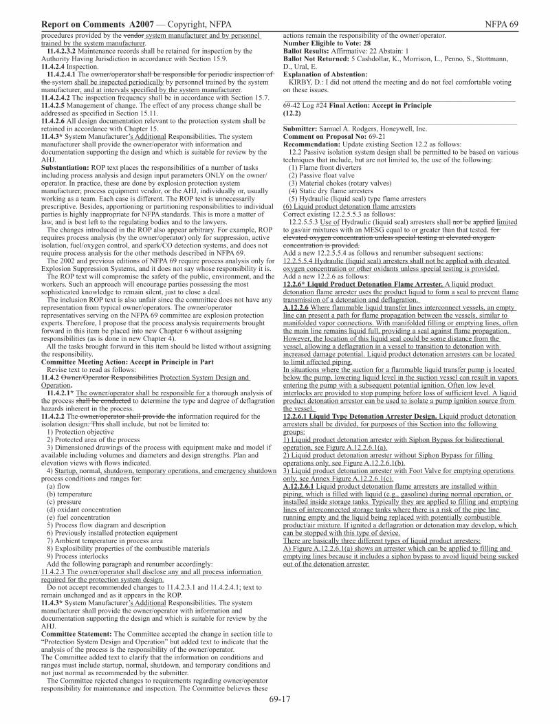
69-�7
Report on Comments A2007 — Copyright, NFPA NFPA 69 procedures provided by the vendor system manufacturer and by personnel trained by the system manufacturer. 11.4.2.3.2 Maintenance records shall be retained for inspection by the Authority Having Jurisdiction in accordance with Section �5.9. 11.4.2.4 Inspection. 11.4.2.4.1 The owner/operator shall be responsible for periodic inspection of the system shall be inspected periodically by personnel trained by the system manufacturer, and at intervals specified by the system manufacturer. 11.4.2.4.2 The inspection frequency shall be in accordance with Section �5.7. 11.4.2.5 Management of change. The effect of any process change shall be addressed as specified in Section �5.��. 11.4.2.6 All design documentation relevant to the protection system shall be retained in accordance with Chapter �5. 11.4.3* System Manufacturer’s Additional Responsibilities. The system manufacturer shall provide the owner/operator with information and documentation supporting the design and which is suitable for review by the AHJ. Substantiation: ROP text places the responsibilities of a number of tasks including process analysis and design input parameters ONLY on the owner/operator. In practice, these are done by explosion protection system manufacturer, process equipment vendor, or the AHJ, individually or, usually working as a team. Each case is different. The ROP text is unnecessarily prescriptive. Besides, apportioning or partitioning responsibilities to individual parties is highly inappropriate for NFPA standards. This is more a matter of law, and is best left to the regulating bodies and to the lawyers. The changes introduced in the ROP also appear arbitrary. For example, ROP requires process analysis (by the owner/operator) only for suppression, active isolation, fuel/oxygen control, and spark/CO detection systems, and does not require process analysis for the other methods described in NFPA 69. The 2002 and previous editions of NFPA 69 require process analysis only for Explosion Suppression Systems, and it does not say whose responsibility it is. The ROP text will compromise the safety of the public, environment, and the workers. Such an approach will encourage parties possessing the most sophisticated knowledge to remain silent, just to close a deal. The inclusion ROP text is also unfair since the committee does not have any representation from typical owner/operators. The owner/operator representatives serving on the NFPA 69 committee are explosion protection experts. Therefore, I propose that the process analysis requirements brought forward in this item be placed into new Chapter 6 without assigning responsibilities (as is done in new Chapter 4). All the tasks brought forward in this item should be listed without assigning the responsibility. Committee Meeting Action: Accept in Principle in Part Revise text to read as follows: 11.4.2 Owner/Operator Responsibilities Protection System Design and Operation. 11.4.2.1* The owner/operator shall be responsible for a thorough analysis of the process shall be conducted to determine the type and degree of deflagration hazards inherent in the process. 11.4.2.2 The owner/operator shall provide the information required for the isolation design. This shall include, but not be limited to: �) Protection objective 2) Protected area of the process 3) Dimensioned drawings of the process with equipment make and model if available including volumes and diameters and design strengths. Plan and elevation views with flows indicated. 4) Startup, normal, shutdown, temporary operations, and emergency shutdown process conditions and ranges for: (a) flow (b) temperature (c) pressure (d) oxidant concentration (e) fuel concentration 5) Process flow diagram and description 6) Previously installed protection equipment 7) Ambient temperature in process area 8) Explosibility properties of the combustible materials 9) Process interlocks Add the following paragraph and renumber accordingly: ��.4.2.3 The owner/operator shall disclose any and all process information required for the protection system design. Do not accept recommended changes to ��.4.2.3.� and ��.4.2.4.�; text to remain unchanged and as it appears in the ROP. 11.4.3* System Manufacturer’s Additional Responsibilities. The system manufacturer shall provide the owner/operator with information and documentation supporting the design and which is suitable for review by the AHJ. Committee Statement: The Committee accepted the change in section title to “Protection System Design and Operation” but added text to indicate that the analysis of the process is the responsibility of the owner/operator. The Committee added text to clarify that the information on conditions and ranges must include startup, normal, shutdown, and temporary conditions and not just normal as recommended by the submitter. The Committee rejected changes to requirements regarding owner/operator responsibility for maintenance and inspection. The Committee believes these
actions remain the responsibility of the owner/operator. Number Eligible to Vote: 28 Ballot Results: Affirmative: 22 Abstain: � Ballot Not Returned: 5 Cashdollar, K., Morrison, L., Penno, S., Stottmann, D., Ural, E. Explanation of Abstention: KIRBY, D.: I did not attend the meeting and do not feel comfortable voting on these issues. _______________________________________________________________ 69-42 Log #24 Final Action: Accept in Principle (12.2) ________________________________________________________________ Submitter: Samuel A. Rodgers, Honeywell, Inc. Comment on Proposal No: 69-2� Recommendation: Update existing Section �2.2 as follows: �2.2 Passive isolation system design shall be permitted to be based on various techniques that include, but are not limited to, the use of the following: (�) Flame front diverters (2) Passive float valve (3) Material chokes (rotary valves) (4) Static dry flame arresters (5) Hydraulic (liquid seal) type flame arresters (6) Liquid product detonation flame arresters Correct existing �2.2.5.5.3 as follows: �2.2.5.5.3 Use of Hydraulic (liquid seal) arresters shall not be applied limited to gas/air mixtures with an MESG equal to or greater than that tested. for elevated oxygen concentration unless special testing at elevated oxygen concentration is provided. Add a new �2.2.5.5.4 as follows and renumber subsequent sections: �2.2.5.5.4 Hydraulic (liquid seal) arresters shall not be applied with elevated oxygen concentration or other oxidants unless special testing is provided. Add a new �2.2.6 as follows: 12.2.6* Liquid Product Detonation Flame Arrester. A liquid product detonation flame arrester uses the product liquid to form a seal to prevent flame transmission of a detonation and deflagration. A.12.2.6 Where flammable liquid transfer lines interconnect vessels, an empty line can present a path for flame propagation between the vessels, similar to manifolded vapor connections. With manifolded filling or emptying lines, often the main line remains liquid full, providing a seal against flame propagation. However, the location of this liquid seal could be some distance from the vessel, allowing a deflagration in a vessel to transition to detonation with increased damage potential. Liquid product detonation arresters can be located to limit affected piping. In situations where the suction for a flammable liquid transfer pump is located below the pump, lowering liquid level in the suction vessel can result in vapors entering the pump with a subsequent potential ignition. Often low level interlocks are provided to stop pumping before loss of sufficient level. A liquid product detonation arrestor can be used to isolate a pump ignition source from the vessel. 12.2.6.1 Liquid Type Detonation Arrester Design. Liquid product detonation arresters shall be divided, for purposes of this Section into the following groups: �) Liquid product detonation arrester with Siphon Bypass for bidirectional operation, see Figure A.�2.2.6.�(a). 2) Liquid product detonation arrester without Siphon Bypass for filling operations only, see Figure A.�2.2.6.�(b). 3) Liquid product detonation arrester with Foot Valve for emptying operations only, see Annex Figure A.�2.2.6.�(c). A.12.2.6.1 Liquid product detonation flame arresters are installed within piping, which is filled with liquid (e.g., gasoline) during normal operation, or installed inside storage tanks. Typically they are applied to filling and emptying lines of interconnected storage tanks where there is a risk of the pipe line running empty and the liquid being replaced with potentially combustible product/air mixture. If ignited a deflagration or detonation may develop, which can be stopped with this type of device. There are basically three different types of liquid product arresters: A) Figure A.�2.2.6.�(a) shows an arrester which can be applied to filling and emptying lines because it includes a siphon bypass to avoid liquid being sucked out of the detonation arrester.
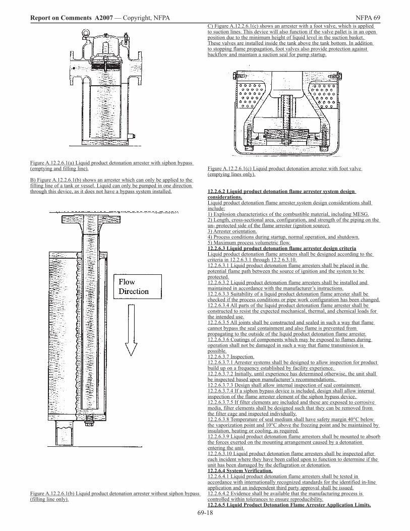
69-�8
Report on Comments A2007 — Copyright, NFPA NFPA 69
Figure A.�2.2.6.�(a) Liquid product detonation arrester with siphon bypass (emptying and filling line). B) Figure A.�2.2.6.�(b) shows an arrester which can only be applied to the filling line of a tank or vessel. Liquid can only be pumped in one direction through this device, as it does not have a bypass system installed.
Figure A.�2.2.6.�(b) Liquid product detonation arrester without siphon bypass (filling line only).
C) Figure A.�2.2.6.�(c) shows an arrester with a foot valve, which is applied to suction lines. This device will also function if the valve pallet is in an open position due to the minimum height of liquid level in the suction basket. These valves are installed inside the tank above the tank bottom. In addition to stopping flame propagation, foot valves also provide protection against backflow and maintain a suction seal for pump startup.
Figure A.�2.2.6.�(c) Liquid product detonation arrester with foot valve (emptying lines only). 12.2.6.2 Liquid product detonation flame arrester system design considerations. Liquid product detonation flame arrester system design considerations shall include: �) Explosion characteristics of the combustible material, including MESG. 2) Length, cross-sectional area, configuration, and strength of the piping on the un- protected side of the flame arrester (ignition source). 3) Arrester orientation. 4) Process conditions during startup, normal operation, and shutdown. 5) Maximum process volumetric flow. 12.2.6.3 Liquid product detonation flame arrester design criteria Liquid product detonation flame arresters shall be designed according to the criteria in �2.2.6.3.� through �2.2 6.3.�0. �2.2.6.3.� Liquid product detonation flame arresters shall be placed in the potential flame path between the source of ignition and the system to be protected. �2.2.6.3.2 Liquid product detonation flame arresters shall be installed and maintained in accordance with the manufacturer’s instructions. �2.2.6.3.3 Suitability of a liquid product detonation flame arrester shall be checked if the process conditions or pipe work configuration has been changed. �2.2.6.3.4 All parts of the liquid product detonation flame arrester shall be constructed to resist the expected mechanical, thermal, and chemical loads for the intended use. �2.2.6.3.5 All joints shall be constructed and sealed in such a way that flame cannot bypass the seal containment and also flame is prevented from propagating to the outside of the liquid product detonation flame arrester. �2.2.6.3.6 Coatings of components which may be exposed to flames during operation shall not be damaged in such a way that flame transmission is possible. �2.2.6.3.7 Inspection. �2.2.6.3.7.� Arrester systems shall be designed to allow inspection for product build up on a frequency established by facility experience. �2.2.6.3.7.2 Initially, until experience has determined otherwise, the unit shall be inspected based upon manufacturer’s recommendations. �2.2.6.3.7.3 Design shall allow internal inspection of seal containment. �2.2.6.3.7.4 If a siphon bypass device is included, design shall allow internal inspection of the flame arrester element of the siphon bypass device. �2.2.6.3.7.5 If filter elements are included and these are exposed to corrosive media, filter elements shall be designed such that they can be removed from the filter cage and inspected individually. �2.2.6.3.8 Temperature of seal medium shall have safety margin 40°C below the vaporization point and �0°C above the freezing point and be maintained by insulation, heating or cooling, as required. �2.2.6.3.9 Liquid product detonation flame arrestors shall be mounted to absorb the forces exerted on the mounting arrangement caused by a detonation entering the unit. �2.2.6.3.�0 Liquid product detonation flame arresters shall be inspected after each incident where they have been called upon to function to determine if the unit has been damaged by the deflagration or detonation. 12.2.6.4 System Verification. �2.2.6.4.� Liquid product detonation flame arresters shall be tested in accordance with internationally recognized standards for the identified in-line application and an independent third party approval shall be issued. �2.2.6.4.2 Evidence shall be available that the manufacturing process is controlled within tolerances to ensure reproducibility. 12.2.6.5 Liquid Product Detonation Flame Arrester Application Limits.
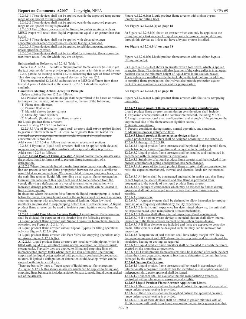
69-�9
Report on Comments A2007 — Copyright, NFPA NFPA 69 �2.2.6.5.� These devices shall not be applied outside the approved temperature range unless special testing is provided. �2.2.6.5.2 These devices shall not be applied outside the approved pressure range unless special testing is provided. �2.2.6.5.3 Use of these devices shall be limited to gas/air mixtures with an MESG (vapor will result from liquid evaporation) equal to or greater than that tested. �2.2.6.5.4 These devices shall not be applied with elevated oxygen concentration or other oxidants unless special testing is provided. �2.2.6.5.5 These devices shall not be applied to self-decomposing mixtures, unless specifically tested. �2.2.6.5.6 These devices shall not be installed for volumetric flows above the maximum tested flow for which they are designed. Substantiation: Reference A.�2.2.4.� Table �. Table � in A.�2.2.4.� includes a “liquid product flame arrester (in-line)” yet the text does not define or provide application criteria for this type. Add a new �2.2.6, parallel to existing section �2.2.5, addressing this type of flame arrester. This also requires updating a listing of devices in Section �2.2. The recommended �2.2.6.5.3 addresses use at MESGs different from those tested. A parallel statement in the current �2.2.5.5.3 should be updated similarly. Committee Meeting Action: Accept in Principle Update existing Section �2.2 as follows: �2.2 Passive isolation system design shall be permitted to be based on various techniques that include, but are not limited to, the use of the following: (�) Flame front diverters (2) Passive float valve (3) Material chokes (rotary valves) (4) Static dry flame arresters (5) Hydraulic (liquid seal) type flame arresters (6) Liquid product flame arresters Correct existing �2.2.5.5.3 as follows: �2.2.5.5.3 Use of Hydraulic (liquid seal) arresters shall not be applied limited to gas/air mixtures with an MESG equal to or greater than that tested. for elevated oxygen concentration unless special testing at elevated oxygen concentration is provided. Add a new �2.2.5.5.4 as follows and renumber subsequent sections: �2.2.5.5.4 Hydraulic (liquid seal) arresters shall not be applied with elevated oxygen concentration or other oxidants unless special testing is provided. Add a new �2.2.6 as follows: 12.2.6* Liquid Product Flame Arrester. A liquid product flame arrester uses the product liquid to form a seal to prevent flame transmission of a deflagration. A.12.2.6 Where flammable liquid transfer lines interconnect vessels, an empty line can present a path for flame propagation between the vessels, similar to manifolded vapor connections. With manifolded filling or emptying lines, often the main line remains liquid full, providing a seal against flame propagation. However, the location of this liquid seal could be some distance from the vessel, allowing a deflagration in a vessel to transition to detonation with increased damage potential. Liquid product flame arresters can be located to limit affected piping. In situations where the suction for a flammable liquid transfer pump is located below the pump, lowering liquid level in the suction vessel can result in vapors entering the pump with a subsequent potential ignition. Often low level interlocks are provided to stop pumping before loss of sufficient level. A liquid product flame arrestor can be used to isolate a pump ignition source from the vessel. 12.2.6.1 Liquid Type Flame Arrester Design. Liquid product flame arresters shall be divided, for purposes of this Section into the following groups: �) Liquid product flame arrester with Siphon Bypass for bidirectional transfer operation, see Figure A.�2.2.6.�(a). 2) Liquid product flame arrester without Siphon Bypass for filling operations only, see Figure A.�2.2.6.�(b). 3) Liquid product flame arrester with Foot Valve for emptying operations only, see Annex Figure A.�2.2.6.�(c). A.12.2.6.1 Liquid product flame arresters are installed within piping, which is filled with liquid (e.g., gasoline) during normal operation, or installed inside storage tanks. Typically they are applied to filling and emptying lines of interconnected storage tanks where there is a risk of the pipe line running empty and the liquid being replaced with potentially combustible product/air mixture. If ignited a deflagration or detonation could develop, which can be stopped with this type of device. There are basically three different types of liquid product flame arresters: A) Figure A.�2.2.6.�(a) shows an arrester which can be applied to filling and emptying lines because it includes a siphon bypass to avoid liquid being sucked out of the arrester.
Figure A.�2.2.6.�(a) Liquid product flame arrester with siphon bypass (emptying and filling line).
See Figure A.12.2.6.1(a) on page 18 B) Figure A.�2.2.6.�(b) shows an arrester which can only be applied to the filling line of a tank or vessel. Liquid can only be pumped in one direction through this device, as it does not have a bypass system installed. See Figure A.12.2.6.1(b) on page 18
Figure A.�2.2.6.�(b) Liquid product flame arrester without siphon bypass (filling line only). C) Figure A.�2.2.6.�(c) shows an arrester with a foot valve, which is applied to suction lines. This device will also function if the valve pallet is in an open position due to the minimum height of liquid level in the suction basket. These valves are installed inside the tank above the tank bottom. In addition to stopping flame propagation, foot valves also provide protection against backflow and maintain a suction seal for pump startup. See Figure A.12.2.6.1(c) on page 18 Figure A.�2.2.6.�(c) Liquid product flame arrester with foot valve (emptying lines only). 12.2.6.2 Liquid product flame arrester system design considerations. Liquid product flame arrester system design considerations shall include: �) Explosion characteristics of the combustible material, including MESG. 2) Length, cross-sectional area, configuration, and strength of the piping on the unprotected side of the flame arrester (ignition source). 3) Arrester orientation. 4) Process conditions during startup, normal operation, and shutdown. 5) Maximum process volumetric flow. 12.2.6.3 Liquid product flame arrester design criteria Liquid product flame arresters shall be designed according to the criteria in �2.2.6.3.� through �2.2 6.3.�0. �2.2.6.3.� Liquid product flame arresters shall be placed in the potential flame path between the source of ignition and the system to be protected. �2.2.6.3.2 Liquid product flame arresters shall be installed and maintained in accordance with the manufacturer’s instructions. �2.2.6.3.3 Suitability of a liquid product flame arrester shall be checked if the process conditions or piping configuration has been changed. �2.2.6.3.4 All parts of the liquid product flame arrester shall be constructed to resist the expected mechanical, thermal, and chemical loads for the intended use. �2.2.6.3.5 All joints shall be constructed and sealed in such a way that flame cannot bypass the seal containment and also flame is prevented from propagating to the outside of the liquid product flame arrester. �2.2.6.3.6 Coatings of components which may be exposed to flames during operation shall not be damaged in such a way that flame transmission is possible. �2.2.6.3.7 Inspection. �2.2.6.3.7.� Arrester systems shall be designed to allow inspection for product build up on a frequency established by facility experience. �2.2.6.3.7.2 Initially, until experience has determined otherwise, the unit shall be inspected based upon manufacturer’s recommendations. �2.2.6.3.7.3 Design shall allow internal inspection of seal containment. �2.2.6.3.7.4 If a siphon bypass device is included, design shall allow internal inspection of the flame arrester element of the siphon bypass device. �2.2.6.3.7.5 If filter elements are included and these are exposed to corrosive media, filter elements shall be designed such that they can be removed for inspection. �2.2.6.3.8 Temperature of seal medium shall have safety margin 40°C below the vaporization point and �0°C above the freezing point and be maintained by insulation, heating or cooling, as required. �2.2.6.3.9 Liquid product flame arrestors shall be mounted to absorb the forces exerted on the mounting arrangement. �2.2.6.3.�0 Liquid product flame arresters shall be inspected after each incident where they have been called upon to function to determine if the unit has been damaged by the deflagration. 12.2.6.4 System Verification. �2.2.6.4.� Liquid product flame arresters shall be tested in accordance with internationally recognized standards for the identified in-line application and an independent third party approval shall be issued. �2.2.6.4.2 Evidence shall be available that the manufacturing process is controlled within tolerances to ensure reproducibility. 12.2.6.5 Liquid Product Flame Arrester Application Limits. �2.2.6.5.� These devices shall not be applied outside the approved temperature range unless special testing is provided. �2.2.6.5.2 These devices shall not be applied outside the approved pressure range unless special testing is provided. �2.2.6.5.3 Use of these devices shall be limited to gas/air mixtures with an MESG (vapor will result from liquid evaporation) equal to or greater than that
69-20
Report on Comments A2007 — Copyright, NFPA NFPA 69 tested. �2.2.6.5.4 These devices shall not be applied with elevated oxygen concentration or other oxidants unless special testing is provided. �2.2.6.5.5 These devices shall not be applied to self-decomposing mixtures, unless specifically tested. �2.2.6.5.6 These devices shall not be installed for volumetric flows above the maximum tested flow for which they are designed. Committee Statement: Since the scope and application of NFPA 69 states that the standard does not apply to devices or equipment designed to protect against detonations, the Committee recommends deleting the word detonation throughout the proposed text. Other changes are editorial. Number Eligible to Vote: 28 Ballot Results: Affirmative: 22 Abstain: � Ballot Not Returned: 5 Cashdollar, K., Morrison, L., Penno, S., Stottmann, D., Ural, E. Explanation of Abstention: KIRBY, D.: I did not attend the meeting and do not feel comfortable voting on these issues. _______________________________________________________________ 69-43 Log #CC4 Final Action: Accept (12.2.4.4.14.3) ________________________________________________________________ Submitter: Technical Committee on Explosion Protection Systems, Comment on Proposal No: 69-2� Recommendation: Revise text to read as follows: �2.2.4.4.�4.3 If exposed to corrosive media, filter elements shall be designed so that they can be removed for inspection from the filter cage and inspected individually or replaced. Substantiation: The revised text makes this requirement more generic and not limited to any one specific design. Committee Meeting Action: Accept Number Eligible to Vote: 28 Ballot Results: Affirmative: 22 Abstain: � Ballot Not Returned: 5 Cashdollar, K., Morrison, L., Penno, S., Stottmann, D., Ural, E. Explanation of Abstention: KIRBY, D.: I did not attend the meeting and do not feel comfortable voting on these issues. _______________________________________________________________ 69-44 Log #22 Final Action: Accept (13.3.4) ________________________________________________________________ Submitter: Samuel A. Rodgers, Honeywell, Inc. Comment on Proposal No: 69-20 Recommendation: Correct the dimension reference in �3.3.4 as follows: Where: Pmawp = enclosure design pressure [barg (psig)] according to ASME Boiler and Pressure Vessel Code Pi = maximum initial pressure at which combustible atmosphere exists [bar (psig)] R = dimensionless pressure ratio Fu = ratio of ultimate stress of the enclosure to the allowable stress of the enclosure per the ASME Boiler and Pressure Vessel Code Fy = ratio of the yield stress of the enclosure to the allowable stress of the materials of construction of the enclosure per the ASME Boiler and Pressure Vessel Code Substantiation: Reference �3.3.4 (Deflagration Containment) Formulae �3.� and �3.2 are shown with dimensional correction factors for Pmawp and Pi in units of psig, while units are incorrectly shown as dimensioned in either barg or psig. The dimensional correction factor is used since the pressure ratio, R, is based on absolute pressures. Committee Meeting Action: Accept Number Eligible to Vote: 28 Ballot Results: Affirmative: 22 Abstain: � Ballot Not Returned: 5 Cashdollar, K., Morrison, L., Penno, S., Stottmann, D., Ural, E. Explanation of Abstention: KIRBY, D.: I did not attend the meeting and do not feel comfortable voting on these issues. _______________________________________________________________ 69-45 Log #6 Final Action: Reject (14.2.3) ________________________________________________________________ Submitter: Maurizio Barbuzzi, Safety Hi-Tech SRL Comment on Proposal No: 69-22 Recommendation: Revise text to read as follows: �4.2.3 Both types of suppression materials described in this chapter shall satisfy the related explosion suppression test requirements in Section �4.3. Substantiation: Expanded metal (aluminum) mesh and polyurethane foam are different materials with different characteristics and with different related MIL specs. For polyurethane foam, for example, the explosion suppression test requirements depend also on the specific “grade” of the material (the “Double void explosion suppression test setup” is required “For Grade II (fine pore material only)” <see MIL-PRF-8726A, 4.5.�9.2.2>), while for aluminum mesh
overpressure limits are correlated to the different Type/Class of the mesh <see MIL-B-87�62A, 3.5.�>. Committee Meeting Action: Reject Committee Statement: See Committee Action and Statement on 69-50 (Log #5). Number Eligible to Vote: 28 Ballot Results: Affirmative: 22 Abstain: � Ballot Not Returned: 5 Cashdollar, K., Morrison, L., Penno, S., Stottmann, D., Ural, E. Explanation of Abstention: KIRBY, D.: I did not attend the meeting and do not feel comfortable voting on these issues. _______________________________________________________________ 69-46 Log #27 Final Action: Accept in Principle in Part (14.2.4) ________________________________________________________________ Submitter: Samuel A. Rodgers, Honeywell, Inc. Comment on Proposal No: 69-22 Recommendation: Add a new section �4.2.4 after existing �4.2.3 as follows, renumber subsequent sections: �4.2.4 Where the application range is based on the fundamental burning velocity of the protected mixture, the same test method shall be used to compare the burning velocity of the subject mixture to that of near-stoichiometric propane-air. �4.2.4.� The fundamental burning velocity of a near-stoichiometric propane-air mixture shall be taken as 46 cm/sec and test measurements adjusted as necessary. �4.2.4.2 It shall be permitted to use fundamental burning velocities listed in NFPA 68 as the basis for design. Substantiation: Reference �4.2.4.2.3 and �4.2.4.3.2. There is a substantial variation in burning velocity depending on the method used for measurement and the �5% variation from propane only implies a similar test method. These sections should reference NFPA 68 for burning velocities. Committee Meeting Action: Accept in Principle in Part Add the following as annex material to the existing annex A.�4.2.4.2.3 as the first sentence: A.�4.2.4.2.3 Where the application range is based on the fundamental burning velocity of the protected mixture, the same test method should be used to compare the burning velocity of the subject mixture to that of near-stoichiometric propane-air. Committee Statement: The Committee used the recommended text for the first item but added it to the existing Annex item for this section so that it is guidance on the best practice but not a requirement as proposed by the submitter. The Committee did not support including the additional requirements as proposed. Number Eligible to Vote: 28 Ballot Results: Affirmative: 22 Abstain: � Ballot Not Returned: 5 Cashdollar, K., Morrison, L., Penno, S., Stottmann, D., Ural, E. Explanation of Abstention: KIRBY, D.: I did not attend the meeting and do not feel comfortable voting on these issues. _______________________________________________________________ 69-47 Log #7 Final Action: Reject (14.2.4.1) ________________________________________________________________ Submitter: Maurizio Barbuzzi, Safety Hi-Tech SRL Comment on Proposal No: 69-22 Recommendation: Revise text to read as follows: �4.2.4.�...for the other tests in Section �4.2 and �4.3. Classification. The expanded metal mesh shall be of the grades, types, and classes specified herein. Grades Grade �. Untreated Grade 2. Treated (Chromate Conversion Coating) Types Type I. �.5 mil foil, nominal �.6 lb/ft3 (25.6 kg/m3) Type II. 2 mil foil Type II Class A. nominal �.9 lb/ft3 (30.4 kg/m3) Type II Class B. nominal 2.� lb/ft3 (33.6 kg/m3) Type III. 3 mil foil Type III, Class A. nominal 2.5 lb/ft3 (40.0 kg/m3) Type III Class B. nominal 3.0 lb/ft3 (48.0 kg/m3) Substantiation: Characteristics and performance of the mesh depend on the specific Type/Class <see MIL-B-87�62A, �.2>. Committee Meeting Action: Reject Committee Statement: See Committee Action and Statement on 69-50 (Log #5). Number Eligible to Vote: 28 Ballot Results: Affirmative: 22 Abstain: � Ballot Not Returned: 5 Cashdollar, K., Morrison, L., Penno, S., Stottmann, D., Ural, E. Explanation of Abstention: KIRBY, D.: I did not attend the meeting and do not feel comfortable voting on these issues.
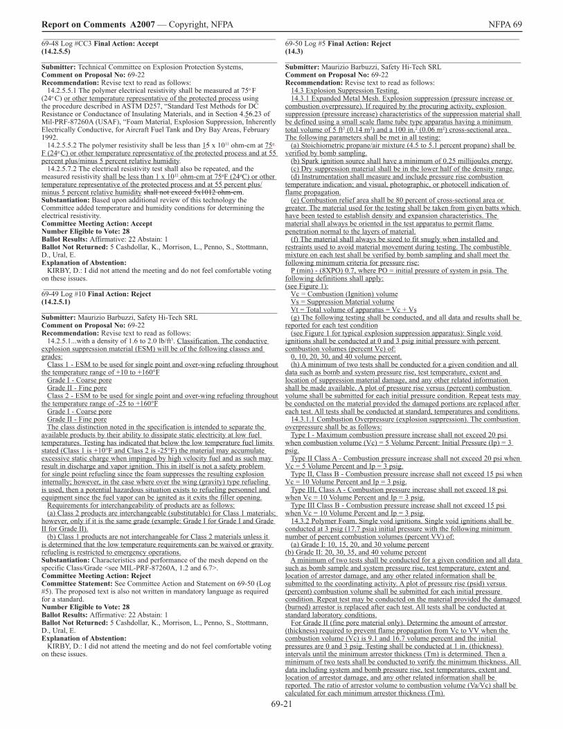
69-2�
Report on Comments A2007 — Copyright, NFPA NFPA 69 _______________________________________________________________ 69-48 Log #CC3 Final Action: Accept (14.2.5.5) ________________________________________________________________ Submitter: Technical Committee on Explosion Protection Systems, Comment on Proposal No: 69-22 Recommendation: Revise text to read as follows: �4.2.5.5.� The polymer electrical resistivity shall be measured at 75o F (24o C) or other temperature representative of the protected process using the procedure described in ASTM D257, “Standard Test Methods for DC Resistance or Conductance of Insulating Materials, and in Section 4.56.23 of Mil-PRF-87260A (USAF), “Foam Material, Explosion Suppression, Inherently Electrically Conductive, for Aircraft Fuel Tank and Dry Bay Areas, February �992. �4.2.5.5.2 The polymer resistivity shall be less than �5 x �0�� ohm-cm at 75o
F (24o C) or other temperature representative of the protected process and at 55 percent plus/minus 5 percent relative humidity. �4.2.5.7.2 The electrical resistivity test shall also be repeated, and the measured resistivity shall be less than � x �0�� ohm-cm at 75oF (24oC) or other temperature representative of the protected process and at 55 percent plus/minus 5 percent relative humidity shall not exceed 5x�0�2 ohm-cm. Substantiation: Based upon additional review of this technology the Committee added temperature and humidity conditions for determining the electrical resistivity. Committee Meeting Action: Accept Number Eligible to Vote: 28 Ballot Results: Affirmative: 22 Abstain: � Ballot Not Returned: 5 Cashdollar, K., Morrison, L., Penno, S., Stottmann, D., Ural, E. Explanation of Abstention: KIRBY, D.: I did not attend the meeting and do not feel comfortable voting on these issues. _______________________________________________________________ 69-49 Log #�0 Final Action: Reject (14.2.5.1) ________________________________________________________________ Submitter: Maurizio Barbuzzi, Safety Hi-Tech SRL Comment on Proposal No: 69-22 Recommendation: Revise text to read as follows: �4.2.5.�...with a density of �.6 to 2.0 lb/ft3. Classification. The conductive explosion suppression material (ESM) will be of the following classes and grades: Class � - ESM to be used for single point and over-wing refueling throughout the temperature range of +�0 to +�60°F Grade I - Coarse pore Grade II - Fine pore Class 2 - ESM to be used for single point and over-wing refueling throughout the temperature range of -25 to +�60°F Grade I - Coarse pore Grade II - Fine pore The class distinction noted in the specification is intended to separate the available products by their ability to dissipate static electricity at low fuel temperatures. Testing has indicated that below the low temperature fuel limits stated (Class � is +�0°F and Class 2 is -25°F) the material may accumulate excessive static charge when impinged by high velocity fuel and as such may result in discharge and vapor ignition. This in itself is not a safety problem for single point refueling since the foam suppresses the resulting explosion internally; however, in the case where over the wing (gravity) type refueling is used, then a potential hazardous situation exists to refueling personnel and equipment since the fuel vapor can be ignited as it exits the filler opening. Requirements for interchangeability of products are as follows: (a) Class 2 products are interchangeable (substitutable) for Class � materials; however, only if it is the same grade (example: Grade I for Grade I and Grade II for Grade II). (b) Class � products are not interchangeable for Class 2 materials unless it is determined that the low temperature requirements can be waived or gravity refueling is restricted to emergency operations. Substantiation: Characteristics and performance of the mesh depend on the specific Class/Grade <see MIL-PRF-87260A, �.2 and 6.7>. Committee Meeting Action: Reject Committee Statement: See Committee Action and Statement on 69-50 (Log #5). The proposed text is also not written in mandatory language as required for a standard. Number Eligible to Vote: 28 Ballot Results: Affirmative: 22 Abstain: � Ballot Not Returned: 5 Cashdollar, K., Morrison, L., Penno, S., Stottmann, D., Ural, E. Explanation of Abstention: KIRBY, D.: I did not attend the meeting and do not feel comfortable voting on these issues.
_______________________________________________________________ 69-50 Log #5 Final Action: Reject (14.3) ________________________________________________________________ Submitter: Maurizio Barbuzzi, Safety Hi-Tech SRL Comment on Proposal No: 69-22 Recommendation: Revise text to read as follows: �4.3 Explosion Suppression Testing. �4.3.� Expanded Metal Mesh. Explosion suppression (pressure increase or combustion overpressure). If required by the procuring activity, explosion suppression (pressure increase) characteristics of the suppression material shall be defined using a small scale flame tube type apparatus having a minimum total volume of 5 ft3 (0.�4 m3) and a �00 in.2 (0.06 m2) cross-sectional area. The following parameters shall be met in all testing: (a) Stoichiometric propane/air mixture (4.5 to 5.� percent propane) shall be verified by bomb sampling. (b) Spark ignition source shall have a minimum of 0.25 millijoules energy. (c) Dry suppression material shall be in the lower half of the density range. (d) Instrumentation shall measure and include pressure rise combustion temperature indication; and visual, photographic, or photocell indication of flame propagation. (e) Combustion relief area shall be 80 percent of cross-sectional area or greater. The material used for the testing shall be taken from given batts which have been tested to establish density and expansion characteristics. The material shall always be oriented in the test apparatus to permit flame penetration normal to the layers of material. (f) The material shall always be sized to fit snugly when installed and restraints used to avoid material movement during testing. The combustible mixture on each test shall be verified by bomb sampling and shall meet the following minimum criteria for pressure rise: P (min) - (8XPO) 0.7, where PO = initial pressure of system in psia. The following definitions shall apply: (see Figure �): Vc = Combustion (Ignition) volume Vs = Suppression Material volume Vt = Total volume of apparatus = Vc + Vs (g) The following testing shall be conducted, and all data and results shall be reported for each test condition (see Figure � for typical explosion suppression apparatus): Single void ignitions shall be conducted at 0 and 3 psig initial pressure with percent combustion volumes (percent Vc) of: 0, �0, 20, 30, and 40 volume percent. (h) A minimum of two tests shall be conducted for a given condition and all data such as bomb and system pressure rise, test temperature, extent and location of suppression material damage, and any other related information shall be made available. A plot of pressure rise versus (percent) combustion volume shall be submitted for each initial pressure condition. Repeat tests may be conducted on the material provided the damaged portions are replaced after each test. All tests shall be conducted at standard, temperatures and conditions. �4.3.�.� Combustion Overpressure (explosion suppression). The combustion overpressure shall be as follows: Type I - Maximum combustion pressure increase shall not exceed 20 psi when combustion volume (Vc) = 5 Volume Percent: Initial Pressure (Ip) = 3 psig. Type II Class A - Combustion pressure increase shall not exceed 20 psi when Vc = 5 Volume Percent and Ip = 3 psig. Type II, Class B - Combustion pressure increase shall not exceed �5 psi when Vc = �0 Volume Percent and Ip = 3 psig. Type III, Class A - Combustion pressure increase shall not exceed �8 psi when Vc = �0 Volume Percent and Ip = 3 psig. Type III Class B - Combustion pressure increase shall not exceed �5 psi when Vc = �0 Volume Percent and Ip = 3 psig. �4.3.2 Polymer Foam. Single void ignitions. Single void ignitions shall be conducted at 3 psig (�7.7 psia) initial pressure with the following minimum number of percent combustion volumes (percent VV) of: (a) Grade I: �0, �5, 20, and 30 volume percent (b) Grade II: 20, 30, 35, and 40 volume percent A minimum of two tests shall be conducted for a given condition and all data such as bomb sample and system pressure rise, test temperature, extent and location of arrestor damage, and any other related information shall be submitted to the coordinating activity. A plot of pressure rise (psid) versus (percent) combustion volume shall be submitted for each initial pressure condition. Repeat test may be conducted on the material provided the damaged (burned) arrestor is replaced after each test. All tests shall be conducted at standard laboratory conditions. For Grade II (fine pore material only). Determine the amount of arrestor (thickness) required to prevent flame propagation from Vc to VV when the combustion volume (Vc) is 9.� and �6.7 volume percent and the initial pressures are 0 and 3 psig. Testing shall be conducted at � in. (thickness) intervals until the minimum arrestor thickness (Tm) is determined. Then a minimum of two tests shall be conducted to verify the minimum thickness. All data including system and bomb pressure rise, test temperatures, extent and location of arrestor damage, and any other related information shall be reported. The ratio of arrestor volume to combustion volume (Va/Vc) shall be calculated for each minimum arrestor thickness (Tm).
69-22
Report on Comments A2007 — Copyright, NFPA NFPA 69 Substantiation: Expanded metal (aluminum) mesh and polyurethane foam are different materials with different characteristics and with different related MIL specs. For polyurethane foam, for example, the explosion suppression test requirements depend also on the specific “grade” of the material: the “Double void explosion suppression test setup” is required “For Grade II (fine pore material only)” <see MIL-PRF-8726A, 4.5.�9.2.2>. For expanded metal mesh the text refers to MIL-B-87�62A “Baffle material, explosion suppression, expanded aluminum mesh, for aircraft fuel tanks”; if MIL specs related to other metal alloys are available, the specific requirements should also be included. Committee Meeting Action: Reject Committee Statement: The recommended text is applicable to just propane/air mixtures, while the application in this standard needs to cover other gas mixtures. The use of types, grades, and classes, to delineate acceptable suppression results is directed towards and limited to aircraft, as this is all based upon propane/air as opposed to testing with the actual combustible material. The Committee has developed the requirements in this Chapter to apply to all classes of foam or mesh in a single performance requirement rather than have a separate set of requirements for each class of foam or mesh. The Committee notes that it is not the intent of this Chapter to replace the MIL-SPEC that defines each class of foam or mesh characteristics and testing, however NFPA 69 takes advantage of the experience in the design and use of the test apparatus. The Committee does not support the proposed pressure/volume criteria in the submitter’s recommended text in �4.3.�.� as NFPA 69 is intended for more general applications than those for which the MIL-SPEC is intended. Number Eligible to Vote: 28 Ballot Results: Affirmative: 22 Abstain: � Ballot Not Returned: 5 Cashdollar, K., Morrison, L., Penno, S., Stottmann, D., Ural, E. Explanation of Abstention: KIRBY, D.: I did not attend the meeting and do not feel comfortable voting on these issues. _______________________________________________________________ 69-5� Log #8 Final Action: Reject (14.3.5) ________________________________________________________________ Submitter: Maurizio Barbuzzi, Safety Hi-Tech SRL Comment on Proposal No: 69-22 Recommendation: Revise text to read as follows: �4.3.5...with an ignition source of at least 0.25 millijoules �0 Joule energy... Substantiation: As per MIL-B-87�62A, 4.4.�.8b and MIL-PRF-87260A, 4.5.�9b. Committee Meeting Action: Reject Committee Statement: See Committee Action and Statement on 69-50 (Log #5). As this test is intended to be applied to a range of chemicals, the Committee notes that the 0.25 millijoules ignition energy would not be sufficient for all chemicals within the chemical industry. Number Eligible to Vote: 28 Ballot Results: Affirmative: 22 Abstain: � Ballot Not Returned: 5 Cashdollar, K., Morrison, L., Penno, S., Stottmann, D., Ural, E. Explanation of Abstention: KIRBY, D.: I did not attend the meeting and do not feel comfortable voting on these issues. _______________________________________________________________ 69-52 Log #4 Final Action: Reject (14.4.5.1) ________________________________________________________________ Submitter: Maurizio Barbuzzi, Safety Hi-Tech SRL Comment on Proposal No: 69-22 Recommendation: Revise text to read as follows: �4.4.5.� Mesh or fFoam installations shall be initially inspected for any evidence of deterioration at intervals of no greater than six months. Expanded metal mesh shall be inspected for any evidence of deterioration at interval of not greater than 4 years. Substantiation: According on document number WC6EI-H�-00�53-OR (investigation performed by NAVAVNDEPOT, Pensacola, Florida, on �00 gallon auxiliary “drop” tanks filled with aluminum expanded metal mesh), deterioration of metal mesh is very slow compared to polymeric foam. Committee Meeting Action: Reject Committee Statement: The general proposed application for this material in the chemical industry increases the likelihood of corrosion attack and the Committee believes that an initial inspection for all types of mesh or foam is necessary. In addition, Chapter �5 allows for adjustment of inspection intervals to reflect any differences in the stability of the mesh types based upon experience and application. Number Eligible to Vote: 28 Ballot Results: Affirmative: 22 Abstain: � Ballot Not Returned: 5 Cashdollar, K., Morrison, L., Penno, S., Stottmann, D., Ural, E. Explanation of Abstention: KIRBY, D.: I did not attend the meeting and do not feel comfortable voting on these issues.
_______________________________________________________________ 69-53 Log #2 Final Action: Accept in Principle (15.10.2) ________________________________________________________________ Submitter: James Everitt, Western Regional Fire Code Development Committee Comment on Proposal No: 69-23 Recommendation: Revise to read: 15.10.2 Initial and annual refresher training shall be provided to personnel who operate, maintain, supervise, or are exposed to equipment and processes protected by explosion prevention systems. Training shall include:...” Substantiation: Systems are tested quarterly but there are no frequency requirements for operators in and around explosion prevention systems. It would seem logical that during every other test the persons in and around the equipment be trained. Committee Meeting Action: Accept in Principle Revise to read: 15.10.2 Initial and, at a minimum, annual refresher training shall be provided to personnel who operate, maintain, supervise, or are exposed to equipment and processes protected by explosion prevention systems. Training shall include:...”. Committee Statement: Clarify that refresher training should be provided at least annually. This action accomplishes the intent of the submitter and clarifies this requirement. Number Eligible to Vote: 28 Ballot Results: Affirmative: 22 Abstain: � Ballot Not Returned: 5 Cashdollar, K., Morrison, L., Penno, S., Stottmann, D., Ural, E. Explanation of Abstention: KIRBY, D.: I did not attend the meeting and do not feel comfortable voting on these issues. _______________________________________________________________ 69-54 Log #20 Final Action: Accept (A.12.2.2.4(1)) ________________________________________________________________ Submitter: Erdem A. Ural, Loss Prevention Science & Technologies, Inc. Comment on Proposal No: 69-2� Recommendation: Revise text to read as follows: A.�2.2.2.4(�) The most challenging situation for a float valve is at the fuel lean and rich conditions, opposite of most other isolation techniques. This is due to the need for the closing forces to be generated by the deflagration itself. Substantiation: Fuel-lean and fuel-rich conditions also challenge the success of certain other deflagration isolation techniques. Remove the words “opposite of most other isolation techniques.” Committee Meeting Action: Accept Number Eligible to Vote: 28 Ballot Results: Affirmative: 22 Abstain: � Ballot Not Returned: 5 Cashdollar, K., Morrison, L., Penno, S., Stottmann, D., Ural, E. Explanation of Abstention: KIRBY, D.: I did not attend the meeting and do not feel comfortable voting on these issues. _______________________________________________________________ 69-55 Log #25 Final Action: Accept in Principle (A.12.2.4.1) ________________________________________________________________ Submitter: Samuel A. Rodgers, Honeywell, Inc. Comment on Proposal No: 69-2� Recommendation: Revise text: (page 96 of ROP) This knowledge allows flexible pipe length installations in the test set-up as well as specific limits for use: For example, the ratio of pipe length (between the potential ignition source and the flame arrester) and pipe diameter shall is not to exceed the tested ratio. A considerable safety margin is introduced by the requirement that at least �0 % of the cross sectional area of the pipe shall has to be open on the ignition source side (for example the mouth of a burner injection) [3] (page 96 of ROP) In addition to this, some detonation arrester test standards, such as FM, CSA and USCG may call for long-time burn test. This, at least in theory, shall should protect from the hazard in which a flame may stabilize on the surface of the in-line flame arrester element. (page �02 of ROP) The selection of the suitable safety measures depends upon the operational possibilities and needs precise consideration by a specialist consultant. The in-line deflagration flame arrester, which shall be installed, should be installed as close as possible to the operational ignition source. It is necessary to choose a temperature-monitored deflagration flame arrester for detecting stable flame on the arrester surface. The installation of an in-line deflagration arrester provides the lowest pressure drop. (page �02 of ROP) In addition to the deflagration flame arrester, a burner inlet combined with volume flow control for air/nitrogen supply, for insuring ensuring a minimum cross sectional flow velocity in case the minimum volume flow is exceeded, is a useful tool to protect against flashback. However, it shall should only be accepted as an independent measure if it has an independent approval as a dynamic flame trap. Substantiation: Reference Chapter �2 A.�2.2.4.�. The above annex statements contain an obligatory “shall”, which could be
69-23
Report on Comments A2007 — Copyright, NFPA NFPA 69 misinterpreted. In addition, the word “insuring” is more correctly “ensuring”: Committee Meeting Action: Accept in Principle In A.�2.2.4.�, in the section dealing with inline hazard and test procedure, following figure A.�2.2.4.�(5) revise the text as follows: (page 96 of ROP) This knowledge allows flexible pipe length installations in the test setup as well as specific limits for use: For example, the ratio of pipe length (between the potential ignition source and the flame arrester) and pipe diameter shall is not to exceed the tested ratio. A considerable safety margin is introduced by the requirement that at least �0 % of the cross sectional area of the pipe shall has to be open on the ignition source side (for example the mouth of a burner injection) [3] (page 96 of ROP) In addition to this, some detonation arrester test standards, such as FM, CSA and USCG may call for longtime burn test. This, at least in theory, shall should protect from the hazard in which a flame may stabilize on the surface of the inline flame arrester element. (page �02 of ROP) The selection of the suitable safety measures depends upon the operational possibilities and needs precise consideration by a specialist consultant. The inline deflagration flame arrester, which shall be installed, should be installed as close as possible to the operational ignition source. It is necessary to choose a temperature-monitored deflagration flame arrester for detecting stable flame on the arrester surface. An inline deflagration arrester produces a lower pressure drop than an inline detonation arrester. The installation of an inline deflagration arrester provides the lowest pressure drop. (Page �02 of ROP) In addition to the deflagration flame arrester, a burner inlet combined with volume flow control for air/nitrogen supply, for insuring ensuring a minimum cross sectional flow velocity in case the minimum volume flow is exceeded, is a useful tool to protect against flashback. However, it shall should only be accepted as an independent measure if it has an independent approval as a dynamic flame trap. Committee Statement: The Committee added a new sentence to clarify the intent of the sentence referencing lower pressure drop when using inline deflagration arresters. Number Eligible to Vote: 28 Ballot Results: Affirmative: 22 Abstain: � Ballot Not Returned: 5 Cashdollar, K., Morrison, L., Penno, S., Stottmann, D., Ural, E. Explanation of Abstention: KIRBY, D.: I did not attend the meeting and do not feel comfortable voting on these issues. _______________________________________________________________ 69-56 Log #CC2 Final Action: Accept (A.12.2.4.1) ________________________________________________________________ Submitter: Technical Committee on Explosion Protection Systems, Comment on Proposal No: n/a Recommendation: In Annex material A.�2.2.4.� Step 5 revise the existing text as follows: Step 5: Evaluate process plant classification Hazardous Areas ο Class� Div. � Hazardous (Classified) Location (normally hazardous) (NEC) Zone 0 normally or frequently hazardous (EC, IEC, NEC) ο Class� Div. � Hazardous (Classified) Location (normally hazardous) (NEC) Zone � occasionally hazardous (EC, IEC, NEC) ο Class� Div.2 Hazardous (Classified) Location (not normally hazardous) (NEC) Zone 2 not normally hazardous (EC, IEC, NEC) Explanation to zones: Zone 0 Hazardous explosive Atmosphere continuously or long term available (>�000 h/a) Zone � Hazardous explosive Atmosphere occasionally available (�0-�000 h/a) Zone 2 Hazardous explosive Atmosphere not or short term available (0-�0 h/a) Substantiation: The Committee revised the information in the Annex to be consistent with the NEC nomenclature for hazardous (classified) locations. The Zone explanation previously contained here was redundant and was deleted. Committee Meeting Action: Accept Number Eligible to Vote: 28 Ballot Results: Affirmative: 22 Abstain: � Ballot Not Returned: 5 Cashdollar, K., Morrison, L., Penno, S., Stottmann, D., Ural, E. Explanation of Abstention: KIRBY, D.: I did not attend the meeting and do not feel comfortable voting on these issues. Comment on Affirmative: FELDKAMP, R.: “Class � Div �” and “Class � Div 2” must have the class in Roman Numeral as follows: “Class I Div � and Class I Div 2.
_______________________________________________________________ 69-57 Log #23 Final Action: Accept (A.13.3.4) ________________________________________________________________ Submitter: Samuel A. Rodgers, Honeywell, Inc. Comment on Proposal No: 69-20 Recommendation: Revise text to read as follows: A.�3.3.4 When determining the Pmawp to contain the deflagration, the calculated minimum design value for Pmawp shall be permitted to will be less than the actual peak pressure expected during the deflagration. Deflagration is a short term pressure excursion and this method is recognized in ASME Boiler and Pressure Vessel Code. The formulas are based on a paper by Noronha et al., “Deflagration Pressure Containment for Vessel Safety Containment for Vessel Safety Design, Plant/Operations Progress.” See NFPA-68 for a more detailed description of the forces imposed during a deflagration. Substantiation: Reference A.�3.3.4. This annex item contains what appears to be a mandatory statement, and should be modified to inform the user of the possibility without use of mandatory language. Committee Meeting Action: Accept Number Eligible to Vote: 28 Ballot Results: Affirmative: 22 Abstain: � Ballot Not Returned: 5 Cashdollar, K., Morrison, L., Penno, S., Stottmann, D., Ural, E. Explanation of Abstention: KIRBY, D.: I did not attend the meeting and do not feel comfortable voting on these issues.
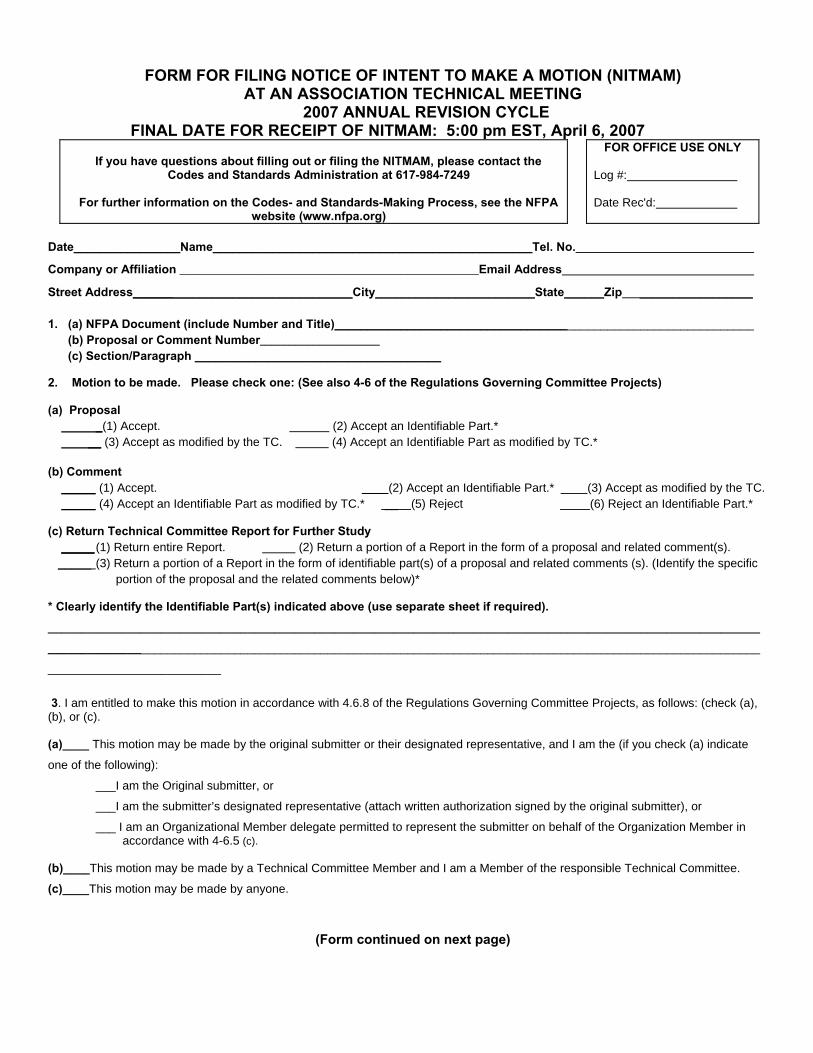
FORM FOR FILING NOTICE OF INTENT TO MAKE A MOTION (NITMAM)
AT AN ASSOCIATION TECHNICAL MEETING 2007 ANNUAL REVISION CYCLE
FINAL DATE FOR RECEIPT OF NITMAM: 5:00 pm EST, April 6, 2007
If you have questions about filling out or filing the NITMAM, please contact the Codes and Standards Administration at 617-984-7249
For further information on the Codes- and Standards-Making Process, see the NFPA
website (www.nfpa.org)
FOR OFFICE USE ONLY
Log #: Date Rec'd:
Date________________Name________________________________________________Tel. No.
Company or Affiliation __________________________________________________Email Address
Street Address_________________________________City________________________State______Zip _________________ 1. (a) NFPA Document (include Number and Title)_______________________________________________________________ (b) Proposal or Comment Number____________________ (c) Section/Paragraph _____________________________________
2. Motion to be made. Please check one: (See also 4-6 of the Regulations Governing Committee Projects) (a) Proposal _(1) Accept. (2) Accept an Identifiable Part.* __ (3) Accept as modified by the TC. (4) Accept an Identifiable Part as modified by TC.* (b) Comment (1) Accept. (2) Accept an Identifiable Part.* (3) Accept as modified by the TC. (4) Accept an Identifiable Part as modified by TC.* __ (5) Reject (6) Reject an Identifiable Part.* (c) Return Technical Committee Report for Further Study _____ (1) Return entire Report. (2) Return a portion of a Report in the form of a proposal and related comment(s). _____ (3) Return a portion of a Report in the form of identifiable part(s) of a proposal and related comments (s). (Identify the specific portion of the proposal and the related comments below)* * Clearly identify the Identifiable Part(s) indicated above (use separate sheet if required). ______________________________________________________________________________________________________________________________________________________________________________________________________________________
__________________________
3. I am entitled to make this motion in accordance with 4.6.8 of the Regulations Governing Committee Projects, as follows: (check (a), (b), or (c). (a)____ This motion may be made by the original submitter or their designated representative, and I am the (if you check (a) indicate
one of the following):
___I am the Original submitter, or
___I am the submitter’s designated representative (attach written authorization signed by the original submitter), or
___ I am an Organizational Member delegate permitted to represent the submitter on behalf of the Organization Member in accordance with 4-6.5 (c). (b)____This motion may be made by a Technical Committee Member and I am a Member of the responsible Technical Committee.
(c)____This motion may be made by anyone.
(Form continued on next page)

NITMAM form (continued) 4. Comments or Clarification (optional): This NITMAM will be reviewed by a Motions Committee. In addition to determining whether your Amending Motion is proper, the Committee may take other actions as described in 2.3 of the Technical Meeting Convention Rules as follows:
Restating and Grouping of Motions. Upon request or on its own initiative, and in consultation with the mover(s), the Motions Committee may: (a) restate an Amending Motion to facilitate the making of a proper motion or to clarify the intent of the mover; and (b) group Amending Motions that are dependent on one another into a single Amending Motion. Dependent motions are motions that the mover(s) wish to be considered by the assembly and voted on as single up or down package. In addition to the foregoing, the Motions Committee may take such other actions or make such other recommendations as will facilitate the fair and efficient consideration of amending.
The NFPA Staff may contact you to clarify your motion or to consult on the permitted actions in 2.3. If you have any comments, suggestions, or requests of the Motions Committee as it reviews your NITMAM and considers actions permitted in 2.3, please provide them below. (Use additional sheet if necessary): __________________________________________________________________________________________________________________________
__________________________________________________________________________________________________________________________
_________________________________________________________________________________________________________________________
__________________________________________________________________________________________________________________________
__________________________________________________________________________________________________________________________
__________________________________________________________________________________________________________________________
__________________________________________________________________________________________________________________________
__________________________________________________________________________________________________________________________
__________________________________________________________________________________________________________________________
__________________________________________________________________________________________________________________________
__________________________________________________________________________________________________________________________
__________________________________________________________________________________________________________________________
Name (please print):_____________________________________________________________________
Signature (Required)_____________________________________________________________________ (Note: This NITMAM will be reviewed, and if proper, your Amending Motion will be certified in accordance with the Technical Meeting Convention Rules and posted on the NFPA website by May 4, 2007. Documents that have Certified Amending Motions will be considered at the June 2007 Annual Meeting Technical Committee Report. In order to have your Certified Amending Motion considered at that meeting, you must appear, sign in, and make the motion as prescribed in the Convention Rules).
PLEASE USE A SEPARATE NITMAM FORM FOR EACH AMENDING MOTION YOU WISH TO MAKE,
Mail to: Secretary, Standards Council, National Fire Protection Association, 1 Batterymarch Park, Quincy, MA 02169-7471 NFPA Fax: (617) 770-3500
Sequence of Events Leading to Issuance of an NFPA Committee Document
Step 1 Call for Proposals
▼ Proposed new Document or new edition of an existing Document is entered into one of two yearly revision cycles, and a Call for Proposals is published.
Step 2 Report on Proposals (ROP)
▼ Committee meets to act on Proposals, to develop its own Proposals, and to prepare its Report.
▼ Committee votes by written ballot on Proposals. If two-thirds approve, Report goes forward. Lacking two-thirds approval, Report returns to Committee.
▼ Report on Proposals (ROP) is published for public review and comment.
Step 3 Report on Comments (ROC)
▼ Committee meets to act on Public Comments to develop its own Comments, and to prepare its report.
▼ Committee votes by written ballot on Comments. If two-thirds approve, Reports goes forward. Lacking two-thirds approval, Report returns to Committee.
▼ Report on Comments (ROC) is published for public review.
Step 4 Technical Report Session
▼ “Notices of intent to make a motion” are filed, are reviewed, and valid motions are certified for presentation at the Technical Report Session. (“Consent Documents” that have no certified motions bypass the Technical Report Session and proceed to the Standards Council for issuance.)
▼ NFPA membership meets each June at the Annual Meeting Technical Report Session and acts on Technical Committee Reports (ROP and ROC) for Documents with “certified amending motions.”
▼ Committee(s) vote on any amendments to Report approved at NFPA Annual Membership Meeting.
Step 5 Standards Council Issuance
▼ Notification of intent to file an appeal to the Standards Council on Association action must be filed within 20 days of the NFPA Annual Membership Meeting.
▼ Standards Council decides, based on all evidence, whether or not to issue Document or to take other action, including hearing any appeals.
I
The Technical Report Session of the NFPA Annual Meeting
The process of public input and review does not end with the publication of the ROP and ROC. Following the completion of the Proposal and Comment periods, there is yet a further opportunity for debate and discussion through the Technical Report Sessions that take place at the NFPA Annual Meeting.
The Technical Report Session provides an opportunity for the final Technical Committee Report (i.e., the ROP and ROC) on each proposed new or revised code or standard to be presented to the NFPA membership for the debate and consideration of motions to amend the Report. The specific rules for the types of motions that can be made and who can make them are set forth in NFPA’s rules which should always be consulted by those wishing to bring an issue before the membership at a Technical Report Session. The following presents some of the main features of how a Report is handled.
What Amending Motions are Allowed. The Technical Committee Reports contain many Proposals and Comments that the Technical Committee has rejected or revised in whole or in part. Actions of the Technical Committee published in the ROP may also eventually be rejected or revised by the Technical Committee during the development of its ROC. The motions allowed by NFPA rules provide the opportunity to propose amendments to the text of a proposed code or standard based on these published Proposals, Comments and Committee actions. Thus, the list of allowable motions include motions to accept Proposals and Comments in whole or in part as submitted or as modified by a Technical Committee action. Motions are also available to reject an accepted Comment in whole or part. In addition, Motions can be made to return an entire Technical Committee Report or a portion of the Report to the Technical Committee for further study.
The NFPA Annual Meeting, also known as the World SafetyConference and Exposition®, takes place in June of each year. A second Fall membership meeting was discontinued in 2004, so the NFPA Technical Report Session now runs once each yearat the Annual Meeting in June.
Who Can Make Amending Motions. Those authorized to make these motions is also regulated by NFPA rules. In many cases, the maker of the motion is limited by NFPA rules to the original submitter of the Proposal or Comment or his or her duly authorized representative. In other cases, such as a Motion to Reject an accepted Comment, or to Return a Technical Committee Report or a portion of a Technical Committee Report for Further Study, anyone can make these motions. For a complete explanation, NFPA rules should be consulted.
The filing of a Notice of Intent to Make a Motion. Before making an allowable motion at a Technical Report Session, the intended maker of the motion must file, in advance of the session, and within the published deadline, a Notice of Intent to Make a Motion. A Motions Committee appointed by the Standards Council then reviews all notices and certifies all amending motions that are proper. The Motions Committee can also, in consultation with the makers of the motions, clarify the intent of the motions and, in certain circumstances, combine motions that are dependent on each other together so that they can be made in one single motion. A Motions Committee report is then made available in advance of the meeting listing all certified motions. Only these Certified Amending Motions, together with certain allowable Follow-Up Motions (that is, motions that have become necessary as a result of previous successful amending motions) will be allowed at the Technical Report Session.
Consent Documents. Often there are codes and standards up for consideration by the membership that will be non-controversial and no proper Notices of Intent to Make a Motion will be filed. These “Consent Documents” will bypass the Technical Report Session and head straight to the Standards Council for issuance. The remaining Documents are then forwarded to the Technical Report Session for consideration of the NFPA membership.
Important Note: The filing of a Notice of Intent to Make a Motion is a new requirement that takes effect beginning with those Documents scheduled for the Fall 2005 revision cycle that reports to the June 2006 Annual Meeting Technical Report Session. The filing of a Notice of Intent to Make a Motion will not, therefore, be required in order to make a motion at the June 2005 Annual Meeting Technical Report Session. For updates on the transition to the new Notice requirement and related new rules effective for the Fall 2005 revision cycle and the June 2006 Annual Meeting, check the NFPA website.
II

Action on Motions at the Technical Report Session. In order to actually make a Certified Amending Motion at the Technical Report Session, the maker of the motion must sign in at least an hour before the session begins. In this way a final list of motions can be set in advance of the session. At the session, each proposed Document up for consideration is presented by a motion to adopt the Technical Committee Report on the Document. Following each such motion, the presiding officer in charge of the session opens the floor to motions on the Document from the final list of Certified Amending Motions followed by any permissible Follow-Up Motions. Debate and voting on each motion proceeds in accordance with NFPA rules. NFPA membership is not required in order to make or speak to a motion, but voting is limited to NFPA members who have joined at least 180 days prior to the session and have registered for the meeting. At the close of debate on each motion, voting takes place, and the motion requires a majority vote to carry. In order to amend a Technical Committee Report, successful amending motions must be confirmed by the responsible Technical Committee, which conducts a written ballot on all successful amending motions following the meeting and prior to the Document being forwarded to the Standards Council for issuance.
Standards Council Issuance
One of the primary responsibilities of the NFPA Standards Council, as the overseer of the NFPA codes and standards development process, is to act as the official issuer of all NFPA codes and standards. When it convenes to issue NFPA documents it also hears any appeals related to the Document. Appeals are an important part of assuring that all NFPA rules have been followed and that due process and fairness have been upheld throughout the codes and standards development process. The Council considers appeals both in writing and through the conduct of hearings at which all interested parties can participate. It decides appeals based on the entire record of the process as well as all submissions on the appeal. After deciding all appeals related to a Document before it, the Council, if appropriate, proceeds to issue the Document as an official NFPA code or standard. Subject only to limited review by the NFPA Board of Directors, the Decision of the Standards Council is final, and the new NFPA code or standard becomes effective twenty days after Standards Council issuance. The illustration on page 9 provides an overview of the entire process, which takes approximately two full years to complete.
III


![Report on Proposals A2007— Copyright, NFPA NFPA 96 · John W. Rudd, Delaware State Fire Marshal Office, DE [E] (Alt. to R. T. Leicht) Rep. International Fire Marshals Association](https://img.pdfslide.us/doc/110x75/5e772625cdc5871398799907/report-on-proposals-a2007a-copyright-nfpa-nfpa-96-john-w-rudd-delaware-state.jpg)


![Report on Comments A2007 — Copyright, NFPA NFPA 69 · 2007. 1. 29. · Luke S. Morrison, Secretary Professional Loss Control Inc., Canada [SE] Joe R. Barton, Fountaintown, IN [SE]](https://img.pdfslide.us/doc/110x75/5fe2566271bf4700215d5b0c/report-on-comments-a2007-a-copyright-nfpa-nfpa-69-2007-1-29-luke-s-morrison.jpg)