Embed Size (px)
Citation preview

Manual Number 677487-R2
Cascade is a Registered Trademark of Cascade Corporation
cascadecorporation
D-SeriesQuick-Mount™ Sideshifters
ERVICE MANUALS
Contents
INTRODUCTION, Section 1 ....... INSTALLATION, Section 2 ..........
Truck Requirements .............. Truck Preparatron ............... lnstallation ......... Prior to Operation ...
PERIODIC MAINTENANCE; Section 3 TROUBLESHOOTING, Section 4 .....
General Procedures ............. Truck System Requirements .....
Plumbing ....................... Hosing Diagram. ............... Circuit Schematic. ..............
Troubleshooting. ................. SERVICE, Section 5 ...............
Sideshifter Removal and Installation Bearings ......................
Bearing Lubrication ............ Bearing Removal and Installation
Cylinder ....................... Cylinder Speed Adjustment ....... Cylinder Removal and Installation
Cylinder Service ................. Cylinder Disassembly ........... Cylinder Inspection ............. Cylinder Reassembly. ...........
SPECIFICATIONS, Section 6 ........ Hydraulics ...................... Truck Carriage .................. Torque Values, ..................
Page Number
1 1
1
1 2 3 4 5 5 5 5 5 5 6 7 7 8 8 8 9 9 9
10 10 10 11 12 12 12 13
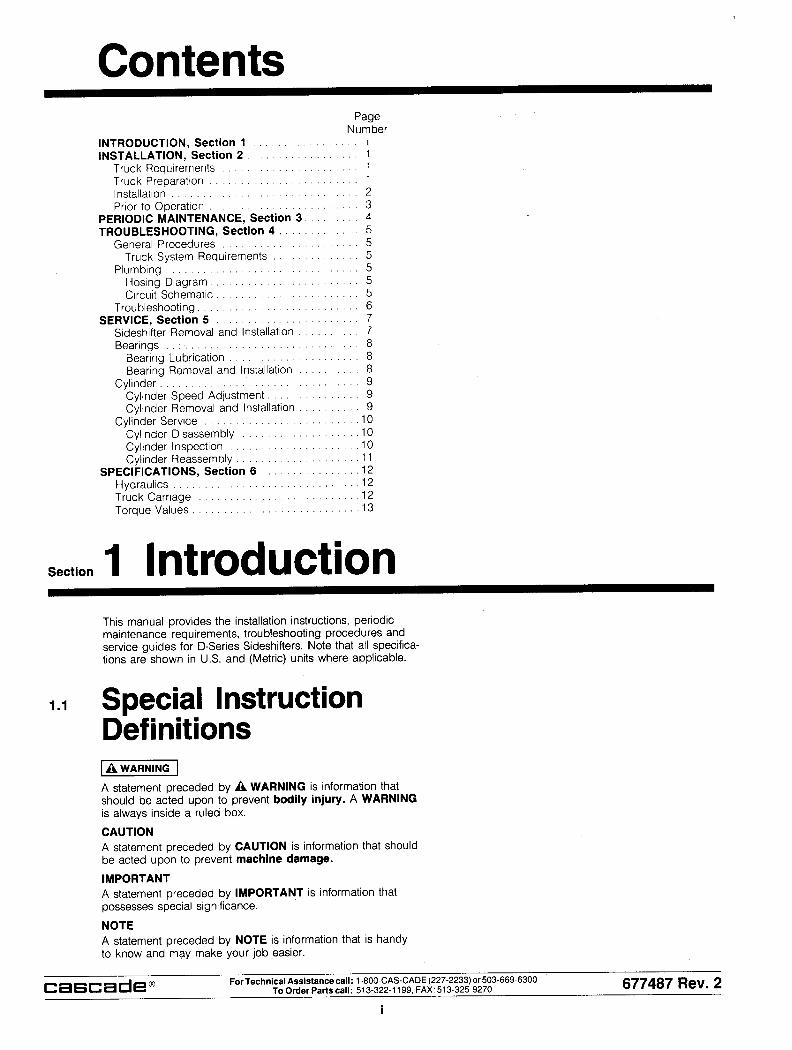
Section 1 Introduction This manual provides the installation instructions, periodic maintenance requirements, troubleshooting procedures and service guides for D-Series Sideshifters. Note that all specifica- tions are shown in US. and (Metric) units where applicable.
1.1 Special Instruction Definitions
A statement preceded by A WARNING is information that should be acted upon to prevent bodily injury. A WARNING is always inside a ruled box.
CAUTION
A statement preceded by CAUTION is information that should be acted upon to prevent machine damage.
IMPORTANT
A statement preceded by IMPORTANT is information that possesses special significance.
NOTE
A statement preceded by NOTE is information that is handy to know and may make your job easier.
cascade@ For Technical Assistance call: 1-800.CASCADE (227-2233) or503-669-6300 To Order Parts call: 513-322-l 199, FAX: 513-325-9270 677487 Rev. 2
i

Section 2 Installation Instructions 2.1 Truck Requirements
l Truck Relief Valve Setting: 3000 psi (210 bar) maximum
l Recommended minimum hose and fitting size:
NO. 4 fitting orifices of 11/64 in. (4.4 mm)
WARNING: Rated capacity of the truck/ sideshifter combination is a responsibility of’
less than that shown on the sideshifter nameplate. Consult the truck nameplate.
l Hydraulic flow should fall within the volume range below:
Hydraulic Specifications 35D/40D/55D/60D 1000 1500
Flow - Minimum0 1 GPM 1 GPM 1 GPM
(4 L/min) (4 L/min) (4 Llmin)
Recommended 2.5 GPM 4 GPM 6 GPM
(95 Llmin) (15 L/min) (23 Llmin)
Maximum@ 3 GPM 5 GPM 12 GPM
(11 L/min) (19 L/min) (45 Llmin)
0 Flows less than minimum could result in erratic sideshift movement.
@ Flows greater than maximum can result in excessive sideshifter speed as well as excessive heating, reduced system performance and shortened hydraulic system life.
l In order to conform to industry standard practice, the hoses should be connected to the truck auxiliary valve as indicated by the chart.
0 Hydraulic Oil - Cascade attachments are compatible with SAE 10W petroleum base oil per Mil. Spec. MIL-0-5606 or MIL-L-2104B. Use of synthetic or aqueous base hydraulic oils is not recommended. Contact Cascade if fire resistant hydraulic oils must be used.
l Truck carriage must conform to Industrial Truck Association ITA dimensions shown, equivalent to IS0
Top Carriage Bar Center Notch
I Function and Motion of the operator’s hand sequence of Attachment when actuating the truck auxil- location to Movement iary control handle while facing the operator
Sideshift
th6 load
Sideshift Right Rearward or Up
Sideshifl Left Forward or Down
2.2 Truck Preparation 1 Remove the forks and backrest from the truck carriage if
equipped.
2 Remove built-up grease and mill scale from the upper and lower truck carriage bars. Remove any burrs or sharp edges. The front surfaces of the carriage bars must be straight within 1/8 in. (3 mm).
3 Inspect the truck top carriage bar center notch. The center notch must meet the dimensions shown in section 2.1 for the sideshifter to mount correctly on the truck carriage.
cascade@ ForTechnical Assistancecall: l-600.CAS-CADE(227.2233)or503-669-6300 To Order Parts call: 513-322-1199, FAX: 513-325-9270 677487 Rev. 2
1
1
2
3
4
5
Section 2 Installation Instructions 2.3 Installation
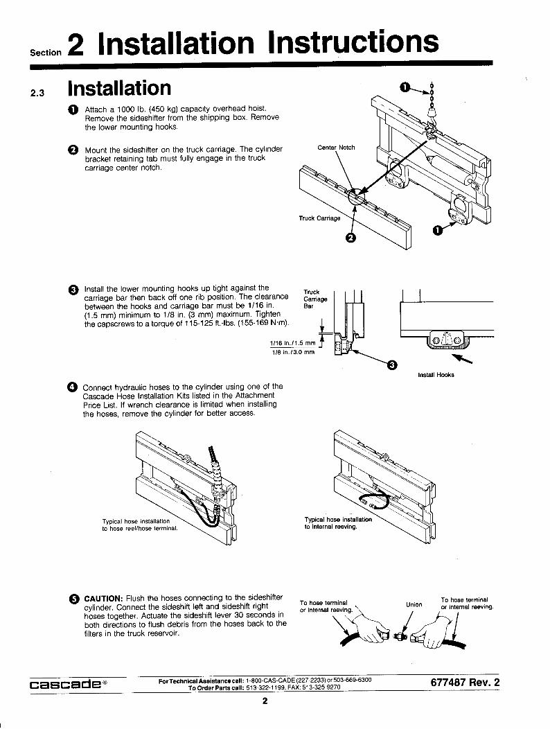
Attach a 1000 lb. (450 kg) capacity overhead hoist. Remove the sideshifter from the shipping box. Remove the lower mounting hooks.
Mount the sideshifter on the truck carriage. The cylinder bracket retaining tab must fully engage in the truck carriage center notch.
Truck Carriage Bar
(1.5 mm) minimum to 1/8 in. (3 mm) maximum. Tighten the capscrews to a torque of 115-125 ft.-lbs. (155-169 N.m).
L
1116 in.11.5 mm F
LG
.: 71 olb
116 in.13.0 mm
Install the lower mounting hooks up tight against the carriage bar then back off one rib position. The clearance between the hooks and carriage bar must be 1/16 in.
Install Hooks
Connect hydraulic hoses to the cylinder using one of the Cascade Hose Installation Kits listed in the Attachment Price List. If wrench clearance is limited when installing the hoses, remove the cylinder for better access.
Typical hose installatio to hose reel/hose term
Typical hose installatio to internal reeving.
CAUTION: Flush the hoses connecting to the sideshifter cylinder. Connect the sideshift left and sideshift right hoses together. Actuate the sideshift lever 30 seconds in both directions to flush debris from the hoses back to the filters in the truck reservoir.
cascade@ For Technical Assistance call: 1-600.CASCADE (227-2233) or503-669-6300 To Order Parts call: 513-322-l 199. FAX: 513-325-9270 677407 Rev. 2
2

Section 2 Installation Instructions 2.3 Installation (Continued)
6 Release the spring lock on the top of each fork. Install the forks on the carriage and lock in positron.
Release the spring lock.
7 Install the backrest and tighten the capscrews to a torque of 50-60 ft.-lbs (70-80 N.m) for Cascade backrests only. Consult lift truck service manual if equipped with truck manufacturer’s backrest.
2.4 Prior to Operation 1 Check for external leaks at the fittings and cylinder rod end
2 Operate the sideshifter through several complete cycles to force any air in the system to the hydraulic tank.
cascade@ ForTechnical Assistancecall: 1-600.CASCADE (227-2233) or 503-669-6300 To Order Parts call: 513-322-l 199, FAX: 513-325-9270 677487 Rev. 2
3

Section 3 Periodic Maintenance
IMPORTANT: After completing any service procedure, always test the sideshifter through 5 complete cycles. First test the side- shifter empty to bleed excess air trapped in the system. Then test with a load to make sure the sideshifter oper- ates correctly before returning it to the job.
3.1 100 Hour Maintenance Every time the lift truck is serviced or every 100 hours of truck operation, whichever comes first, complete the following main- tenance procedures.
‘U Inspect the clearance between the truck lower carriage bar and the sideshifter lower hooks. Retighten the lower hook bolts. See section 5.1 step 6.
3.2 500 Hour Maintenance After each 500 hours of lift truck operation, in addition to the 100-hour maintenance procedure, perform the following:
0 Apply chassis grease to the upper bearing zerk fittings. See section 5.2-1.
3.3 1000 Hour Maintenance After each 1000 hours of lift truck operation, in addition to the 100 hour and 500 hour maintenance procedures, perform the following:
0 Inspect the thickness of the upper bearings. If either of the bearings are worn to less than 1/16 in. (1.5 mm) thick on the back surface, see section 5.2-2 for bearing replacement.
0 Inspect the exposed thickness of the lower bearings. If the thickness is less than 1/16 in. (1.5 mm), see section 5.2-2 for bearing replacement.
3.4 2000 Hour Maintenance After each 2000 hours of lift truck operation, in addition to the 100-hour 500-hour, and 1000-hour maintenance procedures, perform the following:
0 Replace the upper and lower bearing sets. See section 5.2-2.
cascade" ForTechnical Assistancecall: 1-800~CASCADE (227-2233) or503-669-6300 To Order Parts call: 513-322-l 199, FAX: 513-325-9270 677487 Rev. 2
4

Section 4 Troubleshooting 4.1 General Procedures 4.1-1 Truck System Requirements
l The lift truck must supply sufficient hydraulic pressure to A WARNING: Before servicing any hydraulic component, relieve pressure in the system. Turn the truck off, then open the truck aux-
handle the heaviest load. PRESSURE MUST NOT iliary valve several times in both directions.
After completing any service procedure, always test the sideshifter through several cycles. First test the sideshifter empty to bleed air trapped in the system to the truck system. Then test the sideshifter with a load to be sure the sideshifter operates correctly before returning to the job.
Stay clear of the load while testing. Do not raise the load more than 3 in. (75 mm) off
EXCEED 3000 PSI (210 bar).
l Hydraulic Oil - Cascade attachments are compatible with SAE 10W petroleum base oil per Mil. Spec. MIL-0-5606 or MIL-L-2104B. Use of synthetic or aque- ous base hydrualic oils is not recommended. Contact Cascade if fire resistant hydraulic oils must be used.
l Hydraulic flow should fall within the volume range below:
the floor while testing.
Hydraulic Specifications 35D/40D/55D/60D 1OOD 150D
Flow - Minimum@ 1 GPM 1 GPM 1 GPM
(4 L/min) (4 L/min) (4 L/min)
Recommended 2.5 GPM 4 GPM 6 GPM
(9,5 L/min) (15 Llmin) (23 Llmin)
Maximum@ 3 GPM 5 GPM 12 GPM
(11 L/min) (19 L/min) (45 L/min)
@ Flows less than minimum could result in erratic sideshift movement.
@ Flows greater than maximum can result in excessive sideshifter speed as well as excessive heating, reduced system performance and shortened hydraulic system life.
4.2 Plumbing 4.2-1 Hosing Diagram
4.2-2 Circuit Schematic Cylinder
Raat r/ “y& Hose Washer Terminal
Sideshift Auxiliary Valve
,
mdr au f ic Truck Relief Valve Pump
P-Port Hose Reel
/Tl
Hose Terminal
cascade@ ForTechnical Assistancecall: 1-800.CAS-CADE (227-2233) or 503-669-6300 To Order Partscall: 513-322-1199, FAX: 513-325-9270 677487 Rev. 2
5

Section 4 Troubleshooting 4.3 Troubleshooting
There are five potential problem areas that could affect the performance of the sideshifter.
0 Insufficient hydraulic pressure and flow from the lift truck.
Cl External leaks.
0 Worn or defective cylinder seals.
0 Lower mounting hooks installed incorrectly. See section 5.1 step 6.
Cl Worn bearings. See section 5.2-2.
To isolate the problem area, complete the following check list in the exact sequence indicated.
4.3-1 Circuit Pressure Test 1
2
Check the pressure delivered by the truck. Refer to the truck service manual. The pressure must be within 100 psi (7 bar) of specified truck pressure. TRUCK PRESSURE MUST NOT EXCEED 3000 PSI (210 BAR), measured at the hose terminal or internal reeving bulkheads.
Check the flow volume at the hose terminal or internal reeving bulkheads. See chart below for the recommended flow volumes. If the truck pressure and flow volume are correct, proceed with the testing.
Hydraulic Specifications 35D/40D/55D/60D
,
1 OOD 150D
Flow - Minimuma 1 GPM 1 GPM 1 GPM
(4 Llmin) (4 Llmin) (4 Llmin)
Recommended 2.5 GPM 4 GPM 6 GPM
(95 L/min) (15 Llmin) (23 L/min)
Maximum@ 3 GPM 5 GPM 12 GPM
(11 L/min) (19 Llmin) (45 L/min)
@ Flows less than minimum could result in erratic sideshift movement.
@ Flows greater than maximum can result in excessive sideshifter speed as well as excessive heating, reduced system performance and shortened hydraulic system life.
Sideshift completely to the right and hold the control handle in this position for 5 seconds. Check for external leaks at the cylinder, fittings, and hoses.
Sideshift completely to the left and hold the control handle in this position for 5 seconds. Check for external leaks at the cylinder, fittings, and lines.
3
4
WARNING: Before removing the cylinder hose, relieve pressure in the hydraulic sys- tem. Turn the truck off, then actuate the truck sideshift control valve several times in
5. Remove the cylinder base end hose from the hose terminal or internal reeving fitting. Place the hose end in a bucket. Start the truck. Hold the control handle in the sideshift left position for 5 seconds.
l If there is oil flow out of the base end of the cylinder while sideshifting left, the cylinder seals are defective and require service. Refer to paragraph 5.3-2.
l If there is no oil flow out of the base end of the cylinder, the problem is not hydraulic.
’ Place the cylinder base end hose in a bucket.
cascade@ For Technical Assistancecall: 1-800~CASCADE (227-2233) or503-669-6300 To Order Parts call: 513-322-1199. FAX: 513-325-9270 677467 Rev. 2
6

Section 5 Service 5.1 Sideshifter Removal
and Installation 1 Remove the forks from the sideshifter.
2 Remove the backrest from the sideshifter. For reassembly, tighten the capscrews to a torque of 50-60 ft.-lbs. (70-80 N.m) for Cascade backrests only. Consult lift truck service manual if equipped with truck manufacturer’s backrest.
WARNING: Before removing any hoses, relieve pressure in the hydraulic system. Turn the truck off, then actuate the truck sideshift control valve several times in both
I I
3 Disconnect the hoses from the cylinder. If wrench clear- ance is limited, remove the cylinder for better access.
4 Remove the lower mounting hooks.
5 Attach a 1000 lb. (450 kg) capacity overhead hoist Remove the sideshifter from the truck carriage.
6 For installation, reverse the above procedures except for the following special instructions for the lower mounting hooks.
l Install the lower mounting hooks up tight against the carriage bar then back off one rib position. The clear- ance between the hooks and carriage bar must be 1/16 in. (1.5 mm) minimum to 1/8 in. (3.0 mm) maximum. Tighten the capscrews to a torque of 115-125 ft.-lbs. (155-169 N.m).
Truck I III Carriage Bar
1116 in.11.5 mm
l/8 in.13.0 mm
cascade@ For Technical Assistancecall: 1-800~CASCADE (227-2233) or 503-669-6300 To Order Parts call: 513-322-1199, FAX: 513-325-9270 677407 Rev. 2

Section 5 Service 5.2 Bearings
5.2-1 Bearing Lubrication The sideshifter will require lubrication with chassis grease every 500 hours of operation. Apply grease at the zerk fitting lube points shown. Sideshift to expose the upper fittings.
5.2-2 Bearing Removal and Installation 1
2
3
4
5
6
Remove the hairpin cotter and clevis pin from the cylinder rod.
Remove the lower mounting hooks.
Attach a suitable overhead hoist to the sideshifter car- riage. Remove the carriage from the truck. The anchor bracket and bearing segments and cylinder will remain on the truck carriage.
Remove the upper bearing segments. Replace both bear- ing segments if either one is worn to less than 1/16 in. (1.5 mm) thick on the back surface.
Measure the exposed thickness of the lower bearings. If the thickness is less than 1/16 in. (1.5 mm), replace both bearings.
NOTE: The lower bearings have a tight press fit into the bearing cages.
For reassembly, reverse the above procedures except for the following special instructions.
Clean the frame upper hook and lower bearing pockets of any built-up grease.
Clean all parts prior to reassembly.
Install the lower mounting hooks as described in section 5.1 step 6.
After the sideshifter is reassembled and mounted on the truck, apply chassis grease to the bearing zerk fittings. See section 5.2-1 above.
Lubrication
cascade@ For Technical Assistance call: 1-600.CASCADE (227-2233) or503-669-6300 To Order Parts call: 513-322-l 199, FAX: 513-325-9270 677487 Rev. 2
8

Section 5 Service 5.3 Cylinder
5.3-1 Cylinder Speed Adjustment The sideshifting speed can be adjusted by removing or modifying the restrictor washer in the cylinder base end port.
A WARNING: Before removing any hoses, relieve pressure in the hydraulic system. Turn the truck off, then actuate the truck sideshift control valve several times in both directions.
1
2
3
Restrictor Washer
Remove the hose, fitting and restrictor washer from the cylinder base end port.
Increase Speed-Enlarge the restrictor washer orifice to no greater than, 100 in. (2.5 mm) diameter.
NOTE: Completely removing the washer may result in excessive sideshift speed.
Decrease Speed-Braze the restrictor washer orifice closed, then redrill the orifice less than, 080 in. (2 mm) diameter.
Reinstall the parts to the cylinder base end port.
5.3-2 Cylinder Removal and Installation The following procedures can be performed with the side- shifter mounted on the truck.
1 Release the spring lock on the top of each fork. Remove the forks from the sideshifter or slide to the left side.
2 Remove the hairpin cotters and clevis pins from the cylinder ends.
WARNING: Before removing any hoses, relieve pressure in the hydraulic system. Turn the truck off, then actuate the truck sideshift control valve several times in both
3 Disconnect the hydraulic lines from the cylinder ports. Plug the lines and cap the cylinder ports.
4 For reassembly, reverse the above procedures except for the following special instructions.
0 Operate the sideshifter through several full cycles to force air in the system to the truck hydraulic tank. Check for leaks at all fittings.
cascade@ For Technical Assistance call: 1-800.CAS-CADE (227-2233) or503-669-6300 To Order Parts call: 513-322-l 199, FAX: 513.3259270 677487 Rev. 2
9

Section 5 Service 5.4
5.4-l
Cylinder Service
Cylinder Disassembly 1 Clamp the cylinder in a soft-jawed vise. Clamp lightly at
the extreme base end only.
2
3
Position the cylinder rod in the fully extended position. Remove the spiral snap ring from the retainer. See illustration below.
Tap the retainer into the shell approximately 2 In. (50 mm). Remove the retaining ring by placing a screw- driver on one side of the ring near the split and tapping with a hammer. The retaining ring will compress and turn sideways.
4
CAUTION: Do not scratch the cylinder bore.
6
Remove the rod assembly from the cylinder. See illustra- tion below.
5 Clamp the rod assembly in a soft-jawed vise or between two blocks of wood. Never clamp directly on the rod sealing surface. Remove the nut fastening the piston to the rod. Remove the piston and retainer.
Place the piston or retainer in a soft-jawed vise to remove the seals. Pry the seals up with a blunt screwdriver. Cut the seal to remove it.
CAUTION: Do not scratch the seal grooves.
5.4-2 Cylinder Inspection
l Inspect the rod, piston, and retainer for nicks or burrs. Minor nicks and burrs can be removed with emery cloth. If they cannot be removed with emery cloth, replace the part.
l Inspect the cylinder shell bore and snap ring groove. Remove any minor nicks and burrs with emery cloth. If they cannot be removed with the emery cloth, the shell must be replaced.
l Inspect the outside of the shell for any deformities that could weaken the shell’s performance when under pressure. Replace if necessary.
Retainer
, Restrictor Washet
cascade@ For Technical Assistance call: 1 -BOO-CASCADE (227-2233) or503-669-6300 To Order Parts call: 513-322-l 199, FAX: 513-325-9270 677487 Rev. 2
10

Section 5 Service 5.4-3 Cylinder Reassembly
1
2
3
4
5
6
7
8
9
Lubricate all new seals and rings with petroleum jelly or STP.
Note the direction of the U-cup seals. If installed back- ward, the seals will not work properly. For proper seal placement see illustration below.
Polish the piston and retainer chamfer angle with emery cloth. This allows the seal to slide over the chamfer easier.
Install the new seals on the piston and retainer. Hook one side of the seal in the groove and push it over the piston or retainer as shown.
install the retainer and piston on the rod and tighten the piston retaining nut to the torque value below:
35D/40D- 70-75 ft.-lbs. (95-102 N.m) 55D/60D- 70-75 ft.-lbs. (95-102 N.m)
100D/150D- 100-120 ft. Ibs. (135-163 N.m)
Apply a thick film of petroleum jelly or STP to the inside of the cylinder shell, piston seals, and retainer.
Insert the rod assembly into the cylinder shell. If resis- tance is encountered, tap the rod end with a rubber mallet.
0 Install new seals.
Tap the retainer into the shell far enough to install the retaining ring in its groove.
Pull the rod out to the fully extended position. This will position the retainer so the spiral snap ring can be installed.
Back-up Ring Back-up Rings
0 Note seal direction
0 Note seal direction. OR
Special O-Ring (oval) Do not use a standard
MODEL 60D CYLINDER SHOWN
cascade” For Technical Assistance call: l-800.CASCADE (227-2233) or 503-669-6300 To Order Parts call: 513-322-l 199, FAX: 513-325-9270 677407 Rev. 2
11

Section 6 Specifications 6.1-1 Hydraulics
Hydraulic Specifications 35D/40D/55D160D 1OOD
Pressure - Maximum 3000 psi 3000 psi (210 bar) (210 bar)
Flow - Minimum0 1 GPM 1 GPM
(4 Llmin) (4 L/min)
Recommended 2.5 GPM 4 GPM
(9,5 Llmin) (15 L/min)
Maximum@ 3 GPM 5 GPM
(11 L/min) (19 L/min)
Supply Hose and Fitting Size No. 4 No. 4 Minimum Orifice Size 11164in. (4,4mm) 11/64in. (4,4mm)
0 Flows less than minimum could result in erratic sideshift movement.
150D
3000 psi (210 bar)
1 GPM (4 L/min)
6 GPM (23 L/min)
12 GPM (45 L/min)
No. 6 9132 in. (7 mm)
@ Flows greater than maximum can result in excessive sideshifter speed as well as excessive heating, reduced system performance and shortened hydraulic system life.
In order to conform to industry standard practice, the hoses should be connected to the truck auxiliary valve as indicated by the chart.
when actuating the truck auxll- iaty control handle while taclng
Hydraulic Oil - Cascade attachments are compatible with SAE 10W petroleum base oil per Mil. Spec. MIL-0-5606 or MIL-L-2104B. Use of synthetic or aqueous base hydraulic oils is not recommended. Contact Cascade if fire resistant hydrau- lic oils must be used.
6.1-2 Truck Carriage Truck carriage must conform to Industrial Truck Association ITA dimensions shown, equivalent to IS0 standard 2328.
T--f A
a
e
L1
ITA (ISO)
Mounting Carriage Dimensions - in. (mm)
A B C D
Ref. Min. Max. Min. Max. Min. Max.
CLASS II 16.02 14.94 15.00 .32 .36 .60 .66
(407,O) (3795) (381.0) 651) RI) (15.2) (1618)
CLASS Ill 20.00 18.68 18.74 .40 .44 .72 .78
(508,O) (474.5) (476,0) (10,2) (11.2) (18,2) (19.8)
CLASS IV 25.00 23.44 23.50 .47 .51 .72 .78
(6350) (595,3) (597) (12) (13) (18.2) (W3)
Inspect the top carriage bar center notch. The center notch must meet the dimensions shown for the sideshifter to mount correctly on the carriage.
Top Carriage Bar Center Notch
cascade@ For Technical Assistancecall: 1-800.CASCADE (227-2233) or503-669-6300 To Order Park call: 513-322-l 199, FAX: 513-325-9270 677407 Rev. 2
12

Section 6 Specifications 6.1-3 Torque Values
Note that all specifications are shown in U.S. and (Metric) units where applicable.
Cylinder Piston Retaining Nut
cascade@ ForTechnical Assistance call: 1-800.CASCADE (227-2233) or503-669-6300 To Order Parts call: 513-322-l 199, FAX: 513-325-9270 677407 Rev. 2
13
� Cascade Corporation 1989 5-89 Part Number 677487-R2
c
Do you have questions you need answered right now? Call yournearest Cascade Service Department.Visit us online at www.cascorp.com
AMERICASCascade CorporationU.S. Headquarters2201 NE 201stFairview, OR 97024-9718Tel: 800-CASCADE (227-2233)Fax: 888-329-8207
Cascade Canada Inc.5570 Timberlea Blvd.Mississauga, OntarioCanada L4W-4M6Tel: 905-629-7777Fax: 905-629-7785
Cascade do BrasilRua João Guerra, 134Macuco, Santos - SPBrasil 11015-130Tel: 55-13-2105-8800Fax: 55-13-2105-8899
EUROPE-AFRICACascade Italia S.R.L.European HeadquartersVia Dell’Artigianato 137030 Vago di Lavagno (VR) ItalyTel: 39-045-8989111Fax: 39-045-8989160
Cascade (Africa) Pty. Ltd.PO Box 625, Isando 160060A Steel RoadSparton, Kempton ParkSouth AfricaTel: 27-11-975-9240Fax: 27-11-394-1147
ASIA-PACIFICCascade Japan Ltd.2-23, 2-Chome,Kukuchi NishimachiAmagasaki, Hyogo Japan, 661-0978Tel: 81-6-6420-9771Fax: 81-6-6420-9777
Cascade Korea121B 9L Namdong Ind. Complex, 691-8 Gojan-DongNamdong-KuInchon, KoreaTel: +82-32-821-2051Fax: +82-32-821-2055
Cascade-XiamenNo. 668 Yangguang Rd. Xinyang Industrial ZoneHaicang, Xiamen CityFujian ProvinceP.R. China 361026Tel: 86-592-651-2500Fax: 86-592-651-2571
Cascade India Material Handling Private LimitedNo 34, Global Trade Centre 1/1 Rambaugh ColonyLal Bahadur Shastri Road, Navi Peth, Pune 411 030(Maharashtra) IndiaPhone: +91 020 2432 5490Fax: +91 020 2433 0881
Cascade Australia Pty. Ltd.1445 Ipswich RoadRocklea, QLD 4107AustraliaTel: 1-800-227-223Fax: +61 7 3373-7333
Cascade New Zealand15 Ra Ora DriveEast Tamaki, AucklandNew ZealandTel: +64-9-273-9136Fax: +64-9-273-9137
Sunstream IndustriesPte. Ltd.18 Tuas South Street 5Singapore 637796Tel: +65-6795-7555Fax: +65-6863-1368