Embed Size (px)
DESCRIPTION
This guide describes potential corrosion problems in pumpsand valves, and outlines measures that can be taken tominimise these problems. It is not intended that this guidebe used to select the most appropriate pump or valve typefor a specific application, but it does give indications of theapplications for the major types being considered. The guidealso indicates the different kinds of corrosion which may beencountered and the means of avoidance which canbe considered, both for new equipment and items whichhave failed in service.There is a large number of
Citation preview

22
95
/aa
ron
/IK
/00
04
The National Physical Laboratory is operated on behalf of the DTI by NPL Management Limited, a wholly owned subsidiary of Serco Group plc
Guides to Good Practice
in Corrosion Control
Pumpsand Valves

Contents page
1.0 Introduction 1
2.0 General considerations 1
3.0 Types of corrosion 1
3.1 General corrosion 13.2 Localised corrosion 43.3 Galvanic corrosion 43.4 Flow effects 43.5 Environmental cracking 53.6 De-alloying 63.7 Wear 6
4.0 Materials of construction 6
5.0 Protection of external surfaces 8
6.0 Corrosion factors in design 9
7.0 Corrosion factors in use 9
8.0 Materials checklist 10
9.0 Sources of advice 10
10 Further information 10
11.0 References 11
Pumpsand Valves
This is an update of a DTI publication first issued in 1982. The new version
has been prepared by Dr. R. Francis of Weir Materials and Foundries
under contract from NPL for the Department of Trade and Industry.
1.0 Introduction
This guide describes potential corrosion problems in pumps
and valves, and outlines measures that can be taken to
minimise these problems. It is not intended that this guide
be used to select the most appropriate pump or valve type
for a specific application, but it does give indications of the
applications for the major types being considered. The guide
also indicates the different kinds of corrosion which may be
encountered and the means of avoidance which can
be considered, both for new equipment and items which
have failed in service.
There is a large number of pump and valve types, as well
as a wide range of fluids to be handled, so that advice on
design and materials selection in this guide is given in
general terms.
2.0 General considerations
Pumps and valves are designed or chosen primarily for their
mechanical performance i.e. containment of pressure, fluid
sealing and, in the case of pumps, pumping capacity. For
reasons of economy manufacturers offer their products in a
limited range of materials. Each of these materials is suitable
for a range of common fluids, and has the advantage of being
available with relatively short delivery times. However, for
corrosive and/or erosive fluids the user may require special
designs (e.g. of seals) and/or special materials, which
increase cost and delivery times. The balance of cost versus
the likelihood of failure due to corrosion must be taken into
account along with the criticality of the component, i.e. what
are the consequences of a failure. For example, a firewater
pump is a high criticality item and materials should be chosen
so that there is no safety risk.
When requesting non-standard items it is important to realise
that most of the wetted components in a valve or pump are
cast and hence an alloy with good foundry characteristics
must be selected. A compatible wrought alloy must be
selected for items such as shafts and stems. Even when an
alloy is available as a casting, it may not have all the
properties that are required. For example, phosphor bronze
(BS 1400; CT1) is sometimes used for pump impellers, but
rarely for pump or valve bodies because of the difficulty in
producing pressure tight castings in this alloy.
If an alloy change from a standard material involves the
production of wholly new patterns, the additional costs will
be great, and it may be cost effective to consider an alternative
alloy with similar properties which only requires minor
pattern modifications.
When selecting a pump or valve the user must provide the
supplier with details of the composition of the fluid to be
handled (including trace chemicals), the pH, the
temperature, the solids content and the flow rate. Other
factors which are also required for cost effective
materials selection are the desired life and the criticality of
the component i.e. the consequences of an unplanned
shutdown.
Tables 1 and 2 list the common types of pumps and valves
and some of their advantages and disadvantages in relation
to corrosion and allied problems. Nowadays most valve
types can be made fire safe and are available in a range of
common materials. Stem glands will require maintenance
on all types of valves.
3.0 Types of corrosion
3.1 General corrosion
This involves more or less uniform metal dissolution over all
the wetted surfaces. Although this is less serious than
localised corrosion, a number of problems may occur. One
is the reduction of tolerances on items such as wear rings
in pumps, which will result in a loss of pumping efficiency.
Also, the continued release of metal into the fluid may cause
unacceptable levels of contamination.
There are many tables and charts giving data on general
corrosion rates of numerous alloys in a wide range of fluids.
However, care is needed in applying these as much data
have been generated under quiescent or slow flow
conditions, and high velocities can greatly increase
dissolution rates with some materials.
one
Pumps and Valves

Pumps and Valves
two
TYPE DESIGN PROBLEMS ADVANTAGES
Centrifugal
Rotary
Reciprocating
Horizontal
Vertical: in line
Vertical: submerged
Canned: a glandless pump.
Electrical windings separated
from fluid by a thin can of
corrosion resistant alloy.
Gear: two meshing gears
within closed casing.
Lobe: two meshing lobes.
Vane: offset fined impeller.
Screw: helical screw in
elastomeric stator.
Diaphragm: the diaphragm is
forced into reciprocating
motion by mechanical or
hydraulic linkage.
Not usually self-priming and can
lose prime if air/vapour is
present. Poor performance on
viscous liquids.
As above plus: Special motor;
bottom bearing (if fitted)
becomes contaminated.
Smaller mounting area
(footprint).
As above plus: Bottom bearing
exposed to liquids. Liquid drain
down whilst stationary leads to
air/liquid interface within the
pump, and also probably on the
pump or pipework external
surface.
No use for liquids containing
solids because of close
tolerances between stator and
rotor; carbon bearings easily
destroyed.
Rotary pumps are usually not
suitable for handling liquids
containing solids.
Available in most metallic
materials. Small amounts of
corrosion or wear reduce
efficiency. Generally mild steel
or carbon.
Limited materials available for
stator.
Limited materials available for
diaphragms and check valves.
Pulsed flow, which can be
smoothed by the addition of
dampers. Vulnerability of
check-valve materials to
process fluids. Poor with solids,
but designs exist that allow
slurries to be pumped
Available in wide range of
materials. Continuous-flow, free
from large pressure pulsation.
Has no seals and isolates liquids
from motor.
Suitable for all fluids including
viscous fluids. Positive
displacement type pumps
suitable for metering.
Suitable for various speed/
stroke. Can handle viscous
liquids. Capable of high heads.
Fluids isolated from pumping
mechanism.
Table 1. Guide to pump types

three
Pumps and Valves
TYPE FUNCTION DESIGN ADVANTAGES DISADVANTAGES
Gate (wedge)
Gate (parallel)Plug
Globe
Ball
Needle
Butterfly
Diaphragm
Check
Safety
Relief
Bursting disc
On/off throttlingpossible.
On/off throttlingpossible.On/off.
Throttling (needssuitable materials).
On/off.
Throttling.
On/off. Can be usedfor throttling if suitablydesigned.
Throttling can be usedfor on/ off duties.
Prevention ofbackflow.Safety and protection.
Safety and protection.
Safety and protection.
A straight-through valveincorporating a rising-wedge gate.
More sophisticatedversion of wedge.A straight-through valveincorporating a rotatingplug.
Lubricated plug forcritical service underpressure.
Non-lubricated plug(sleeved plug). PTFEsleeve for frictionlessoperation.Widely used forregulating flowconsisting of a risingplug from the seat.Straight-through flow.
Fine regulation of flow.
Very simple designconsisting of a flat discrotating into a seat.
Glandless type of valveincorporating a flexiblediaphragm andavailable either as aweir type or as full bore.Automatically preventsbackflow."Pop-open" valve forgases and vapours(steam).Proportional life valvefor liquids.Protection of plantsystems where veryrapid pressure risesmay occur.
Widely used on water dutiesbut can be used for control ofprocess fluids. Cheap inlarge sizes and generallymade of cast iron.
Used mainly for steam dutiesat high pressure.
Can be fully PTFE-lined andhence have very goodchemical resistance.Wide range of sizes andpressure/ temperatures.
Widely used for corrosiveconditions and range ofpressure/ temperature. Canbe made fire-safe.Suitable for high pressures.
Available in a wide range ofmaterials including manylinings and coatings. Suitablefor large flows of gases,liquids and slurries. Relativelycheap, particularly in largersizes. Slim Design.Widely used for corrosivefluids, but good whereleakage must be avoided.
Wide pressure/temperaturerange.Reseats.
Reseats.
Instantaneous unrestrictedrelief. Wide range ofmaterials available.
When used for throttling maysuffer erosion and wheresolids are carried at highvelocities, seat and wedgemay be hardfaced, (e.g. withStellite 6 or tungstencarbide). The groove in thebase is liable to blockages.Can be "overshut" causingseizure.As above.
Lubricant can causecontamination of productsand limit the temperature ofoperation. Not widely usedbecause of level ofmaintenance required.Pressure/temperatureconditions limited by liningmaterial. Liable to seizure inservice.
Not available as a lined valve.
Poor for throttling. Notsuitable for fluids containingsolids which damage seats.
Available only in smallersizes.
Limited on pressure andtemperature by diaphragmmaterials. Not recommendedfor mains insulation.
Not reliable on critical duties.
Only for gases: preventsexcess pressure.
Only for liquids: preventsexcess pressure.Not-reclosing andexpendable. Subject tocorrosion and creep if hot,causing premature failure.
Table 2 Guide to valve types

3.2 Localised corrosion
There are two main forms of localised corrosion: pitting and
crevice corrosion.
3.2.1 Pitting
This is very localised and pits are often extremely narrow
but deep. Penetration rates can be several mm/y in severe
cases. Pitting occurs when the protective film on the
material breaks down at a small point. Repassivation does
not occur and more metal dissolution takes place. The
environment in the pit is of low pH and generally very high
in chlorides leading to rapid dissolution rates at the base
of the pit. Total metal loss is small but penetration can
occur in a short time.
3.2.2 Crevice corrosion
This occurs where a tight crevice occurs between two
components e.g. a threaded joint or a flanged coupling. The
environment in the crevice quickly becomes deaerated and
metal dissolution inside the crevice increases. There are
two forms of crevice corrosion; one involves a differential
aeration cell between the crevice and the bulk metal, whilst
the other involves a metal ion concentration cell. The former
affects metals such as stainless steels and aluminium
alloys, while the latter affects copper alloys. With a
differential aeration cell the corrosion occurs inside the
crevice, while the corrosion occurs just outside the crevice
with a metal ion concentration cell.
Once initiated this type of attack is similar to pitting and very
high propagation rates can occur under certain conditions.
3.3 Galvanic corrosion
This occurs when two or more dissimilar metals are in
electrical contact and are immersed in a conducting, corrosion
liquid. Corrosion is more likely the further apart the metals
are in the electrochemical series (i.e. the greater the difference
between their open circuit electrochemical potentials in the
fluid in question).
Normally corrosion occurs with potential differences of
200 mV or more, but rapid corrosion can occur in couples
with only 50 to 100 mV difference, if other conditions are
unfavourable. A classic example is preferential corrosion of
weld beads, and it is imperative that the weld material should
have an equivalent or more electropositive potential than
that of the parent metal in the specified fluid.
Galvanic corrosion is strongly influenced by the relative areas
of the two metals, and dissimilar metals are often connected
successfully when the more electronegative material has a
large area compared to the electropositive material. A good
example is the use of 316 stainless steel impellers in
sea water pumps with austenitic cast iron bodies.
The severity of attack is also governed by the temperature
and the cathodic efficiency of the electropositive metal in
the couple. The latter factor governs the critical area ratio
required to avoid problems.
It is important when selecting materials for valves and pumps
to look at all the components in the system to avoid costly
failures due to galvanic corrosion. This should include
not only the valve or pump, but also the piping, to which
it is connected.
3.4 Flow effects
3.4.1 Erosion
This occurs in fluids with high solids contents where material
is mechanically abraded away. Erosion is a function of the
solids content, the cube of the velocity and the angle of impact.
Resistance to erosion increases as the strength and hardness
of the material increases. Alloys which work harden in service
have been used successfully to resist erosion. In severe cases
ceramic coatings/inserts are necessary. Figure 1 shows
severe erosion of a cast iron impeller.
Pumps and Valves
four
Figure 1. Erosion of grey cast iron impeller after two months handling coal dust

3.4.2 Erosion corrosion
This process is also known as impingement attack. It occurs
when turbulent fluids or entrained solids damage the protective
film. The metal then corrodes and the film reforms. Successive
repetitions of this process lead to rapid corrosion. The
corrosion usually occurs locally and takes the form of smooth,
waterswept pits, often undercut. Typical sites of attack are
at the tips of impeller vanes, after sharp bends and after partly
throttled valves, i.e. areas of high turbulence.
3.4.3 Cavitation
This occurs when a sudden decrease in pressure leads to
the formation of vapour cavities. These migrate along the
pressure gradient and collapse at regions of higher
pressure. The mechanical forces at the surface lead to
local loss of metal, which can be severe. Cavitation
occurs in pumps run under non-optimum conditions or
after control valves producing substantial pressure drops.
Attention to detail in design usually avoids this problem
except under abnormal operating conditions.
3.5 Environmental cracking
3.5.1 Stress corrosion cracking (SCC)
This is a very localised form of attack which requires a tensile
stress (either external or internal) and a corrosive liquid.
Different alloys tend to be susceptible to cracking in specific
chemicals and also at specific temperatures. Some common
examples are carbon steels in hot alkaline solutions, austenitic
stainless steels in hot chloride solutions and copper alloys
in ammonia or nitrite containing solutions. Because of
uncertainty in actual operating stresses (including residual
stresses from manufacture and fabrication) it is difficult to
ensure that operating conditions are below the threshold stress
for that alloy system. Alloys, even in one class, vary in their
susceptibi l i ty to stress corrosion cracking and it is
usually possible to select a resistant material. Figure 2
shows stress corrosion cracking of an austentic
cast iron.
3.5.2 Sulphide stress corrosion cracking (SSCC)
This is a special form of stress corrosion cracking which is
of particular concern in oil and gas production and refinery
environments. It requires stresses as for SCC plus the
presence of hydrogen sulphide in solution. The temperature
of greatest susceptibility to SSCC varies from alloy type to
alloy type. In addition to H2S partial pressure and temperature,
the corrosiveness of process brines is also governed by
chloride concentration and pH. The suitability of materials
for sour environments is regulated mostly by NACE document
MR0175, which lists alloys and their limits of use. Qualification
of other alloys or use outside NACE limits requires appropriate
testing such as is described in EFC publications Nos 16 and
17. [For full details see references.]
3.5.3 Hydrogen embrittlement
This occurs under stress as for SCC and when there is also
a source of hydrogen ions, the most common of which is
cathodic protection. Pumps and valves are rarely protected
internally by cathodic protection, but are often subject to it
externally when used subsea. Copper alloys and austenitic
stainless steels are largely immune to hydrogen embrittlement,
whilst other stainless steels, some nickel base alloys and
titanium are susceptible. However, even with susceptible
alloys, the threshold stress for cracking is often well above
the 0.2% proof stress.
five
Pumps and Valves
Figure 2. Stress corrosion cracking in an austenitic cast iron (x70)
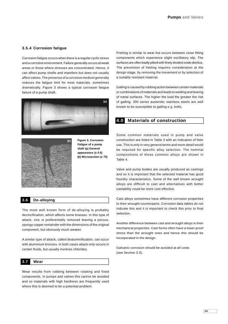
3.5.4 Corrosion fatigue
Corrosion fatigue occurs when there is a regular cyclic stress
and a corrosive environment. Failure generally occurs at weak
areas or those where stresses are concentrated. Hence, it
can affect pump shafts and impellers but does not usually
affect valves. The presence of a corrosive medium generally
reduces the fatigue limit for most materials, sometimes
dramatically. Figure 3 shows a typical corrosion fatigue
failure of a pump shaft.
3.6 De-alloying
The most well known form of de-alloying is probably
dezincification, which affects some brasses. In this type of
attack, zinc is preferentially removed leaving a porous,
spongy copper remainder with the dimensions of the original
component, but obviously much weaker.
A similar type of attack, called dealuminification, can occur
with aluminium bronzes. In both cases attack only occurs in
certain fluids, but usually involves chlorides.
3.7 Wear
Wear results from rubbing between rotating and fixed
components. In pumps and valves this cannot be avoided
and so materials with high hardness are frequently used
where this is deemed to be a potential problem.
Fretting is similar to wear but occurs between close fitting
components which experience slight oscillatory slip. The
surfaces are often badly pitted with finely divided oxide detritus.
The prevention of fretting requires consideration at the
design stage, by removing the movement or by selection of
a suitably resistant material.
Galling is caused by rubbing action between certain materials
or combinations of materials and leads to welding and tearing
of metal surfaces. The higher the load the greater the risk
of galling. 300 series austenitic stainless steels are well
known to be susceptible to galling e.g. bolts.
4.0 Materials of construction
Some common materials used in pump and valve
construction are listed in Table 3 with an indication of their
use. This is only in very general terms and more detail would
be required for specific alloy selection. The nominal
compositions of these common alloys are shown in
Table 4.
Valve and pump bodies are usually produced as castings
and so it is important that the selected material has good
foundry characteristics. Some of the well known wrought
alloys are difficult to cast and alternatives with better
castability could be more cost effective.
Cast alloys sometimes have different corrosion properties
to their wrought counterparts. Corrosion data tables do not
indicate this and it is important to check this prior to final
selection.
Another difference between cast and wrought alloys is their
mechanical properties. Cast forms often have a lower proof
stress than the wrought ones and hence this should be
incorporated in the design.
Galvanic corrosion should be avoided at all costs
(see Section 3.3).
Pumps and Valves
six
Figure 3. CorrosionFatigue of a pumpshaft (a) Generalappearance (x 0.5) (b) Microsection (x 70)
(a)
(b)

seven
Pumps and Valves
PUMP OR VALVE BODY USAGE
Cast Irons/Steel
Grey cast ironMalleable ironNodular (SG) ironCast steel/forged steelAustenitic (Ni-resist) iron
Stainless Steels
Martensitic
Austenitic
DuplexSuper AusteniticSuper Duplex
Copper Alloys
Brass
Bronzes
GunmetalPhosphor Bronze
Aluminium BronzeNickel Aluminium Bronze
Aluminium
Aluminium and Alloys
Nickel Alloys
Alloy 400Alloy 625Alloy 825Alloy B-2Alloy C-276
Titanium and Alloys
Tantalum
Non Metallics
Glass Reinforced Plastic (GRP)
Polyvinylchloride (PVC)Polypropylene
PVDF, FEB, PTFE
Ceramics
Sintered SolidsCoatings
Linings and Coatings
Glass/Enamel
Ebonite, natural rubber, Polypropylene
PVDF, FEP, PTFE
Note
Table 3. Materials of construction for pumps and valves
Water, steam, alkaline conditions, dry solvents, organic substances, strong sulphuric acid.Grey cast iron and carbon steel are unsuitable for use in sea water without protection (such as cathodic protection or coating).
Sea water, brackish water, waste water.
Generally good corrosion resistance to waters, alkalis, some acids and dry solvents.
Oil and gas process fluids.Unsuitable for use in sea water.
Type 304 unsuitable for use in sea water.Type 316 may be used in sea water but can suffer crevice corrosion unless subject to galvanic protection.Alloy 20 used for sulphuric and phosphoric acid duties.
More corrosion resistant than type 316 especially to chloride SCC.Excellent corrosion resistance to a wide range of fluids including sea water, producedwaters, brines, caustic and mineral acids.
Water, steam, unsuitable for use in sea water.
Generally good corrosion resistance in waters including sea waters. Unsuitable for strong alkalis.
Brackish water, sea water.
NAB has good corrosion resistance in sea water. Should not be used where water is ‘sour’i.e. contains hydrogen sulphide.
Not usually used in chemical plant.
Generally good resistance to a wide range of acids and alkalis.
Resistant to sea water and brine but can suffer crevice corrosion.Excellent sea water crevice corrosion resistance.Resistant to organic alkalis and salts, H2S and some acids.Principally used for HCl under reducing conditions (all strengths).Good resistance to a wide range of waters and chemicals.
Suitable for a wide range of acids, alkalis and sea water.
Poor under reducing conditions.
Suitable for water, sea water.
Used for acids and alkalis.
Acids, alkalis, solvents and other organic substances.
Used for valve seats and pump wear ring. Resistant to a wide range of fluids. Care shouldbe taken to ensure that materials containing binders are acceptable for the given duty.
All conditions except pure water, hydrofuoric acid and hot alkalis.
Non-oxidising acids and alkalis.
Most organic substances, acids and alkalis.
Holes in linings and coatings can result in severe corrosion. It is vital that the surface becorrectly prepared before coating and tested after coating.

Pumps and Valves
eight
Table 4. Typical chemical compositions of some common cast materials for pumps and valves
FERROUS AND NICKEL BASE ALLOYS WEIGHT PER CENT
Material Grade C Si Mn P S Cr Ni Mo Others
Ni Resist Cast Iron Flake graphite <3.0 <2.8 <1.5 <0.2 - 2 15 - Cu 6.5
Ni Resist Cast Iron Spheroidal graphite <3.0 <2.2 <1.5 <0.05 - 2 20 - Mg <0.06
Martensitic St Steel 13Cr 4Ni <0.10 <1.0 <1.0 <0.04 <0.03 12.5 4 <0.06
Martensitic St Steel 17Cr 4Ni PH <0.70 <1.0 <0.7 <0.04 <0.03 16.5 4 - Cu 3
Austenitic St Steel (304) 18Cr 8Ni <0.06 <1.5 <2.0 <0.04 <0.04 18 10 -
Austenitic St Steel (316) 18Cr 8Ni 2.5Mo <0.06 <1.5 <2.0 <0.04 <0.04 18 10 2.2
Austenitic St Steel 20Cr Alloy 20 <0.07 <1.5 <1.5 <0.04 <0.04 20 28 2.5 Cu 3
Super Austenitic St Steel 20 Cr 6Mo <0.03 <1.0 <1.2 <0.04 <0.01 20 18 6 N 0.2 Cu 0.7
Duplex St Steel 22Cr <0.03 <1.0 <1.5 <0.03 <0.02 22 6 3 N 0.15
Duplex St Steel 25Cr <0.03 <1.0 <1.5 <0.03 <0.025 25 7 2.5 N 0.2
Super Duplex St Steel 25Cr <0.03 <1.0 <1.0 <0.03 <0.025 25 8 3.5 N 0.25 Cu 0.7 W 0.7
Nickel Copper Alloy Alloy 400 <0.3 <0.5 <2.0 - - - 65 Cu REM Fe<2.5
NiCrMoNb Alloy Alloy 625 <0.15 <0.50 <0.50 <0.15 <0.15 21 REM 9 Al 0.2 Nb 3.5 Ti 0.2 Fe 3
NiCrMoFe Alloy Alloy 825 <0.05 <0.15 <1.0 - - 21.5 42 3 Fe 28 Cu 2 Ti 1
Nickel Molybdenum Alloy Alloy B-2 <0.02 <0.10 <1.0 - - <1.0 REM 28 Co<2.5 Fe<2.0
NiMoCrFeW Alloy Alloy C-276 <0.02 <0.05 <1.0 - - 15.5 REM 16 Co<2.5 Fe 5 W 3.5
NON-FERROUS ALLOYS WEIGHT PER CENT
Material Grade Cu Sn Zn Pb P Ni Others
Leaded Gunmetal 85Cu 5Sn 5PB 5Zn REM 5 5 5 - -
Leaded Gunmetal 87Cu 7Sn 3Pb 3Zn REM 7 2 3 - -
Phosphor Bronze Cu 10Sn P REM 10 - <0.15 0.75 -
Aluminium Bronze Cu 10Al 3 Fe REM - - <0.03 - <1.0 Al 9.5 Fe 2.5
Nickel Aluminium Bronze Cu 10Al 5 Fe 5Ni REM - - <0.03 - 5 Al 9.5 Fe 5
5.0 Protection of external surfaces
External surfaces, including flanges, handwheels, supports,
etc., must be protected against the ambient atmosphere. This
may be anything from a heated indoors dry atmosphere,
through normal industrial or marine, to highly corrosive
atmospheres associated with some industries or even
submerged in a corrosive fluid such as sea water.
External surfaces of pumps and valves are often as vulnerable
as structural steelwork and should therefore be protected
by an appropriate scheme. The Code of Practice BS 5493
is a good guide, but as it was issued in 1977 (albeit with
amendments in 1984 and 1993) there are now good quality
products on the market which have been introduced more
recently and which are well worth consideration.

nine
Pumps and Valves
Surface preparation is a most important part of a painting
system, and if a long life is desired for any location outdoors
or in a damp, wet, indoor atmosphere, grit blast preparation
should be mandatory.
Paint products are formulated for specific applications;
primers to key on to prepared surfaces, undercoats to give
build and body and a finish coat for appearance and to repel
water. A full proper paint system for best protection should
usually include all three.
Whenever possible, the external shape should be designed
to avoid surfaces and pockets where dust and water can
collect. Where this is not possible then it may be necessary
to consider increasing the thickness of the paint system to
prevent failure in local areas.
For items such as pipes or columns and other simple, easy
access shapes then a fusion bonded product is a good form
of coating to use e.g. fusion bond epoxy.
6.0 Corrosion factors in design
When choosing the pump size, its size and the pressure
required to move the fluid, consideration must also be
given to the chemical and physical nature of the fluid.
For example, if the pump is designed to move fluids that are
carrying solids, then the operating velocity range is important.
If the velocity is too low, settling may occur, leading to
crevice corrosion. If the velocity is too high erosion may
occur leading to high localised metal loss. In addition the
rates of diffusion controlled reactions increase with velocity.
Consideration needs to be given to materials, coatings
and pump designs which minimise erosive metal loss. The
same principles also apply to valves operating in the
same environments.
The distribution of pressure and flow within the components
should be such that erosion and cavitation do not occur.
Gaskets should not protrude into the flow, where they can
cause separation and turbulence.
Small items in pumps and valves also need close attention.
For example, threaded drain plugs in contact with the fluid
must be galvanically compatible with the body, if not of the
same material, and must also be resistant to crevice corrosion.
One factor which strongly affects corrosion and is not always
properly appreciated is temperature. Process temperatures
tend to be quoted at pump and valve inlets. However, the
temperature at each location in the device should be
considered, particularly in pumps which can have regions
which are local sources of heat. For example, in centrifugal
pumps pitting and/or crevice corrosion may occur at
mechanical seal faces or on shafts under seal sleeves, due
to local temperature increases, while the rest of the pump
is free of corrosion.
7.0 Corrosion factors in use
Even after the user has selected a pump or valve suitable
for their purpose that avoids the corrosion problems outlined
above, there are actions that can be taken to avoid problems
arising in service.
A common source of corrosion in service is the entry, during
shut down, of air and/or moisture into a normally sealed
system. This can result in corrosion conditions being produced
in areas which retain small volumes of the process fluid. This
can be avoided either by ensuring that all such areas have
suitable drains or by flushing with an innocuous fluid such
as tap water. For carbon and low alloy steels this would also
need the addition of a suitable corrosion inhibitor.
Changes in the composition of the working fluid can cause
corrosion of components which, until then, have performed
satisfactorily. These changes can often be very small, e.g.
the presence of a small quantity of ferric or cupric ions can
turn a reducing fluid to an oxidising one. Other fluid changes
which commonly occur can lead to sudden increases in
corrosion as temperature increases and pH changes. Users
must anticipate such changes in the fluid as far as possible
at the initial design stage, as rectification after a corrosion
failure can often be very expensive, not only because a new
component is required, but also because of the lost production
while the item is repaired/replaced.
Non-metallic components, such as those used for seals,
diaphragms, linings, etc, may be subject to attack resulting
in swelling, brittleness, softening, etc, with time. Manufacturers
usually have extensive experience with a range of materials
and it is important that these issues are discussed at an early
stage so that any special requirements are addressed and
the most suitable design and materials are selected.
Gland packings on pumps and valves are essential to
satisfactory operation. A wide variety of packings are used
and, as above, it is important to discuss particular applications
with the manufacturer so that designs and materials compatible
with the process fluid are chosen.

Pumps and Valves
ten
Note that the use of graphite containing seals/packing may
give rise to galvanic corrosion in some instances.
8.0 Materials checklist
In order to select suitable materials of construction for a specific
pump or valve, the following information is required:
1. Fluid: nature and composition, concentration, pH, aeration, impurities, chemical additions, suspended solids, variations with time.
2. Temperature: minimum, maximum and normal; any possible thermal shocks.
3. Pressure: range, including vacuum.
4. Flow: volume with time, velocity including any local turbulence.
5. Operation: continuous, intermittent, standby.
6. Contamination: effect on fluid of any corrosion products which may be produced.
7. Requirements: reliability required, minimum life, ease and cost of maintenance.
9.0 Sources of advice
Advice on design and choice for a given use can be obtained
from the corrosion advisory centres and consultancy services
listed in the Corrosion Handbook.
The same organisations can investigate failures and make
recommendations for avoiding them in future. Reputable
equipment manufacturers can also offer advise, based on
their experiences.
10.0 Further information
General information is available from the following
organisations:
National Corrosion Service
National Physical Laboratory
Teddington
Middlesex TW11 0LW
Tel: 020 8943 6142
Fax: 020 8943 7107
Institute of Corrosion
4 Leck House
Lake Street
Leighton Buzzard
Bedfordshire LU7 8TQ
Tel: 01525 851771
Fax: 01525 376690
Materials Information Service
Institute of Materials
1 Carlton House Terrace
London SW1Y 5DB
Tel: 020 7451 7350
Tel: 020 7451 7354
Fax: 020 7839 5513
Information on materials is available from the following
organisations:
1. Copper and copper alloys.
CDA
Verulam Industrial Estate
224 London Road
St Albans
Herts AL1 1AQ
Tel: 01727 731200
Fax: 01727 731216
2. Nickel and nickel containing alloys.
NiDI
The Holloway
Alvechurch
Birmingham B48 7QB
Tel: 01527 584 777
Fax: 01527 585 562

eleven
Pumps and Valves
3. Titanium and titanium alloys.
c/o Timet UK Ltd
Kynoch Works
Witton Road
Witton
Birmingham B6 7UR
Tel: 0121 356 1155
Fax: 0121 356 5413
11.0 References
For sources of general information on corrosion and data on
the compatibilities of metal and fluids, see Guide No 1 in this
series.
References on sulphide stress corrosion cracking (section 3.5.2)
MR0175 Sulphide Stress Corrosion Cracking Resistant Metallic Materials for Oilfield Equipment, (revised annually), published by NACE.
EFC 16 Guidelines on Materials Requirements for Carbon and Low Alloy Steels for H2S - Containing Environments in Oil and Gas Production, published by IOM 1995.
EFC 17 Corrosion Resistant Alloys for Oil and Gas Production: Guidance on General Requirements and Test Methods for H2S Service. Published by MPI, 1998.
For sources of advice, see The Corrosion Handbook, published by MPI, 1998.
For information on bimetallic corrosion, see British StandardInstitution publication PD6484.
For information on the protection of external surfaces, see BS5493. Code of Practice for Protective Coating of Iron and SteelStructures Against Corrosion. Last revised 1993. Published by BSI. For information on methods of packaging to prevent damage to coatings during transport, see Guide No 3 in this series.
The following books and papers on pumps and valves are available:
Pumps for progress. 4th Technical Conference of the BritishPump Manufacturers’ Association, 9-10 April 1975, Durham.
Cavitation. I S Pearsall, Chart. Mechanical Engineer, 1974, Vol 2,No 9, pp 79-85.
Practical consideration in the design of oil field water injection systems. C C Patton, mater. Performance, 1977, Vol16, No 11, pp 9-12.
Selecting the right pump. R F Neerken, Chem. Eng. Desk book, 3 April 1978, pp 87-98.
Pump requirements for the chemical process industries.
J R Birk and J H Peakcock, Chem. Eng., 18 February 1974, pp 116-124.
Pumps for corrosive media. M L Booth, Chart. Mech. Eng., January 1977, pp 72-74.
Pumps and the plant design engineer, BHRA Course, 1974, Cranfield Bedfordshire.
Which pump? R A Clarke and G Geddes, Engineering, Novem-ber 1972, pp 1089-92.
Handbook of industrial pipework engineering. E Holmes, McGraw-Hill.
Material Selection: How to achieve the most cost effectivechoice for your pump. R Francis and M Bennett. (Availablefrom Weir Material & Foundries, Grimshaw Lane, Newton Heath,Manchester M40 2BA.)
Take many factors into consideration when selecting pumpmaterials: Parts 1 & 2, by F W Buse.
Chemical Engineering Progress 88,5 (1992) 84Chemical Engineering Progress 88,9 (1992) 50
Material selection for offshore seawater pumps by W G Higgs,P E Redman and J C Brin.
11th Annual Energy Sources Technology Conference, New Orleans, USA. 1988 published by ASME.
Considerations for proper sizing and material selection to opti-mise centrifugal slurry pumps by G Davidson.
4th International Pump Symposium.Houston, USA 1987, published by Texas A & M University.
Considerations in the selection of centrifugal pump materials by T A Layne.
Spring National Meeting, Anaheim, USA, 1982. Published by AIChE.
Materials selection for pumps in flue gas desulphurisationplants by H Tischener.
KSB Tech. Ber. (25e) March 1989, page 33.
Saline Water Pumps: selecting the right materials by A Tuthill.Chem. Eng. 95, 12 (1988) 88.
Selecting materials for recirculating valves used in secondary recovery service, by M Shumacher and J Gossett.
Oil Gas J. 81, 9 (1983) 98.
How to select a non-metallic pump, by E Margues and K Comerford.
Process and Control Engineering, 47, 8 (1994).
Selecting a positive-displacement pump in 10 steps, by J Mayer.
World Pumps, 343, April (1975) 30.
Effect of operating conditions on the wear of wet parts in slurry pumps, by Z Hu and J Cheng.
9th International Conference on the wear of materials, SanFrancisco, USA, April 1993.
Pump and valve manufacturers’ literature.

© Crown Copyright 2000. Reproduced by permission of the Controller of HMSO
The National Corrosion ServiceThe National Corrosion Service (NCS) is operated by NPL on behalf of the DTI to
provide a gateway to corrosion expertise for UK users. By acting as a focal point for
corrosion enquiries, the NCS can make the UK’s entire base of experts available to
solve problems or can, using in-house expertise or teams, carry out consultancy.
The NCS also helps raise awareness of corrosion problems and methods of control.
For more information on NCS services and products please contact us at:
E-mail: [email protected] Tel: 020 8943 6142 Fax: 020 8943 7107
National Physical Laboratory, Queens Road,Teddington, Middlesex TW11 0LW
NPL’s Web Page can be found at: www.npl.co.uk or Email: [email protected] Tel: 020 8943 6880 Fax: 020 8943 6458
22
95
/aa
ron
/IK
/00
04


![NORTA MIT PRESENTATION.pptx [Read-Only] · • Centrifugal pumps • Side channel pumps • Gear pumps • Screw pumps • Single screw pumps • Piston pumps • Vacuum pumps •](https://img.pdfslide.us/doc/110x75/5ec27ab9e3ef591d10504c3a/norta-mit-read-only-a-centrifugal-pumps-a-side-channel-pumps-a-gear-pumps.jpg)