Embed Size (px)
Citation preview

6600 Series Printers Applications Manual
Volume 1
Emulations


6600 Series Printers Applications Manual
Volume 1
Emulations

Trademark AcknowledgementsAcrobat® Reader is a trademark of Adobe Systems Incorporated.
DEC is a trademark of Compaq Computer Corp.
Epson is a trademark of Seiko Epson Corp.
Genicom is a trademark of Genicom L.L.C.
HP is a trademark of Hewlett-Packard Company.
IBM and Proprinter are trademarks of International Business Machines Corporation.
Printronix and PGL are trademarks of Printronix, Inc.
QMS and Code V are trademarks of Minolta-QMS Inc.
TallyGenicom brand is owned by Printronix, Inc.
COPYRIGHT 2010 PRINTRONIX, INC.
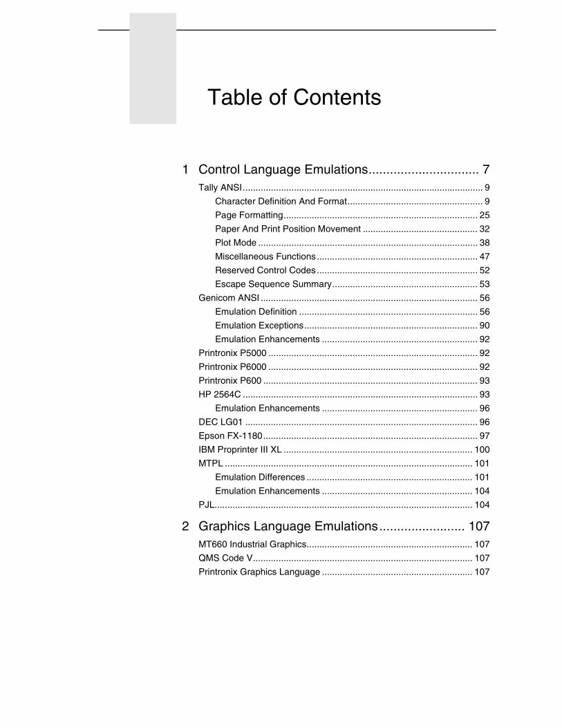
Table of Contents
1 Control Language Emulations............................... 7Tally ANSI.............................................................................................. 9
Character Definition And Format..................................................... 9
Page Formatting............................................................................ 25
Paper And Print Position Movement ............................................. 32
Plot Mode ...................................................................................... 38
Miscellaneous Functions............................................................... 47
Reserved Control Codes............................................................... 52
Escape Sequence Summary......................................................... 53
Genicom ANSI ..................................................................................... 56
Emulation Definition ...................................................................... 56
Emulation Exceptions.................................................................... 90
Emulation Enhancements ............................................................. 92
Printronix P5000 .................................................................................. 92
Printronix P6000 .................................................................................. 92
Printronix P600 .................................................................................... 93
HP 2564C ............................................................................................ 93
Emulation Enhancements ............................................................. 96
DEC LG01 ........................................................................................... 96
Epson FX-1180.................................................................................... 97
IBM Proprinter III XL .......................................................................... 100
MTPL ................................................................................................. 101
Emulation Differences ................................................................. 101
Emulation Enhancements ........................................................... 104
PJL..................................................................................................... 104
2 Graphics Language Emulations........................ 107MT660 Industrial Graphics................................................................. 107
QMS Code V...................................................................................... 107
Printronix Graphics Language ........................................................... 107
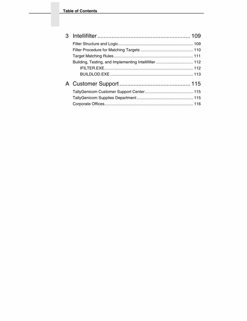
Table of Contents
3 Intellifilter ........................................................... 109Filter Structure and Logic................................................................... 109
Filter Procedure for Matching Targets ............................................... 110
Target Matching Rules....................................................................... 111
Building, Testing, and Implementing Intellifilter ................................. 112
IFILTER.EXE............................................................................... 112
BUILDLOD.EXE .......................................................................... 113
A Customer Support ............................................. 115TallyGenicom Customer Support Center........................................... 115
TallyGenicom Supplies Department .................................................. 115
Corporate Offices............................................................................... 116
1 Control Language
Emulations
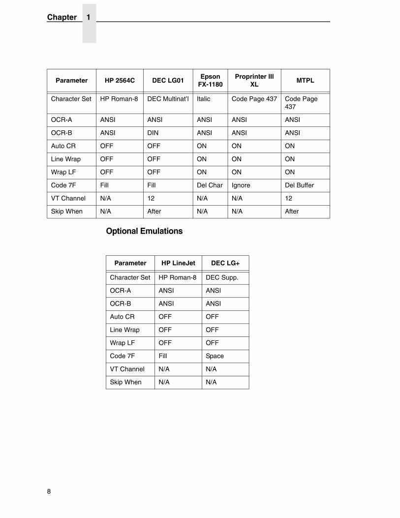
A number of printer control language emulations provide compatibility with existing applications and reduce host programming efforts. The default emulation is Tally ANSI.
When an emulation is selected, the following parameters are set to a default condition required by the emulation:
Parameter Tally ANSI Genicom ANSI P5000 P6000 P600
Character Set Latin 1 Code Page 437 Code Page 437 Latin 1 Latin 1
OCR-A ANSI ANSI ANSI ANSI ANSI
OCR-B ANSI ANSI ANSI ANSI ANSI
Auto CR OFF ON ON ON OFF
Line Wrap OFF ON OFF OFF OFF
Wrap LF OFF ON OFF OFF OFF
Code 7F Fill Fill Space Space Space
VT Channel 2 12 N/A 12 12
Skip When Before Before N/A After After
7
Chapter 1
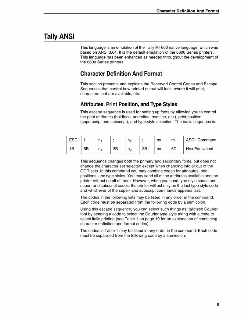
Optional Emulations
Parameter HP 2564C DEC LG01Epson
FX-1180Proprinter III
XLMTPL
Character Set HP Roman-8 DEC Multinat’l Italic Code Page 437 Code Page 437
OCR-A ANSI ANSI ANSI ANSI ANSI
OCR-B ANSI DIN ANSI ANSI ANSI
Auto CR OFF OFF ON ON ON
Line Wrap OFF OFF ON ON ON
Wrap LF OFF OFF ON ON ON
Code 7F Fill Fill Del Char Ignore Del Buffer
VT Channel N/A 12 N/A N/A 12
Skip When N/A After N/A N/A After
Parameter HP LineJet DEC LG+
Character Set HP Roman-8 DEC Supp.
OCR-A ANSI ANSI
OCR-B ANSI ANSI
Auto CR OFF OFF
Line Wrap OFF OFF
Wrap LF OFF OFF
Code 7F Fill Space
VT Channel N/A N/A
Skip When N/A N/A
8
Character Definition And Format
Tally ANSIThis language is an emulation of the Tally MT660 native language, which was based on ANSI 3.64. It is the default emulation of the 6600 Series printers. This language has been enhanced as needed throughout the development of the 6600 Series printers.
Character Definition And Format
This section presents and explains the Reserved Control Codes and Escape Sequences that control how printed output will look, where it will print, characters that are available, etc.
Attributes, Print Position, and Type StylesThis escape sequence is used for setting up fonts by allowing you to control the print attributes (boldface, underline, overline, etc.), print position (superscript and subscript), and type style selection. The basic sequence is:
This sequence changes both the primary and secondary fonts, but does not change the character set selected except when changing into or out of the OCR sets. In this command you may combine codes for attributes, print positions, and type styles. You may send all of the attributes available and the printer will act on all of them. However, when you send type style codes and super- and subscript codes, the printer will act only on the last type style code and whichever of the super- and subscript commands appears last.
The codes in the following lists may be listed in any order in the command. Each code must be separated from the following code by a semicolon.
Using this escape sequence, you can select such things as Italicized Courier font by sending a code to select the Courier type style along with a code to select italic printing (see Table 1 on page 10 for an explanation of combining character definition and format codes).
The codes in Table 1 may be listed in any order in the command. Each code must be separated from the following code by a semicolon.
ESC [ n1 ; n2 ; nx m ASCII Command
1B 5B n1 3B n2 3B nx 6D Hex Equivalent
9
Chapter 1 Tally ANSI
Combining Attributes
Any of the attributes discussed in the ESC [nm sequence may be included in a single escape sequence. The escape sequence begins the same as one requesting a single code but changes after the first attribute byte. A semicolon (;) must be inserted between each code listed in the sequence. For example, to print a single word in a sentence with the boldface and underline attributes, send the following escape sequence
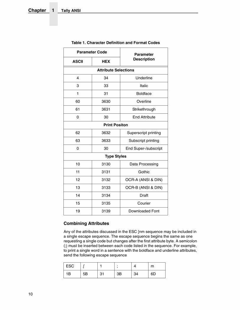
Table 1. Character Definition and Format Codes
Parameter CodeParameter
DescriptionASCII HEX
Attribute Selections
4 34 Underline
3 33 Italic
1 31 Boldface
60 3630 Overline
61 3631 Strikethrough
0 30 End Attribute
Print Positon
62 3632 Superscript printing
63 3633 Subscript printing
0 30 End Super-/subscript
Type Styles
10 3130 Data Processing
11 3131 Gothic
12 3132 OCR-A (ANSI & DIN)
13 3133 OCR-B (ANSI & DIN)
14 3134 Draft
15 3135 Courier
19 3139 Downloaded Font
ESC [ 1 ; 4 m
1B 5B 31 3B 34 6D
10
Character Definition And Format
immediately before the word in the data stream and follow the word with the escape sequence:
Example: To boldface and italicize the word "only" in the sentence:
Enter: Boldface and italicize the word ESC[1;3monlyESC[0m in this sentence.
Printer Output: Boldface and italicize the word only in this sentence.
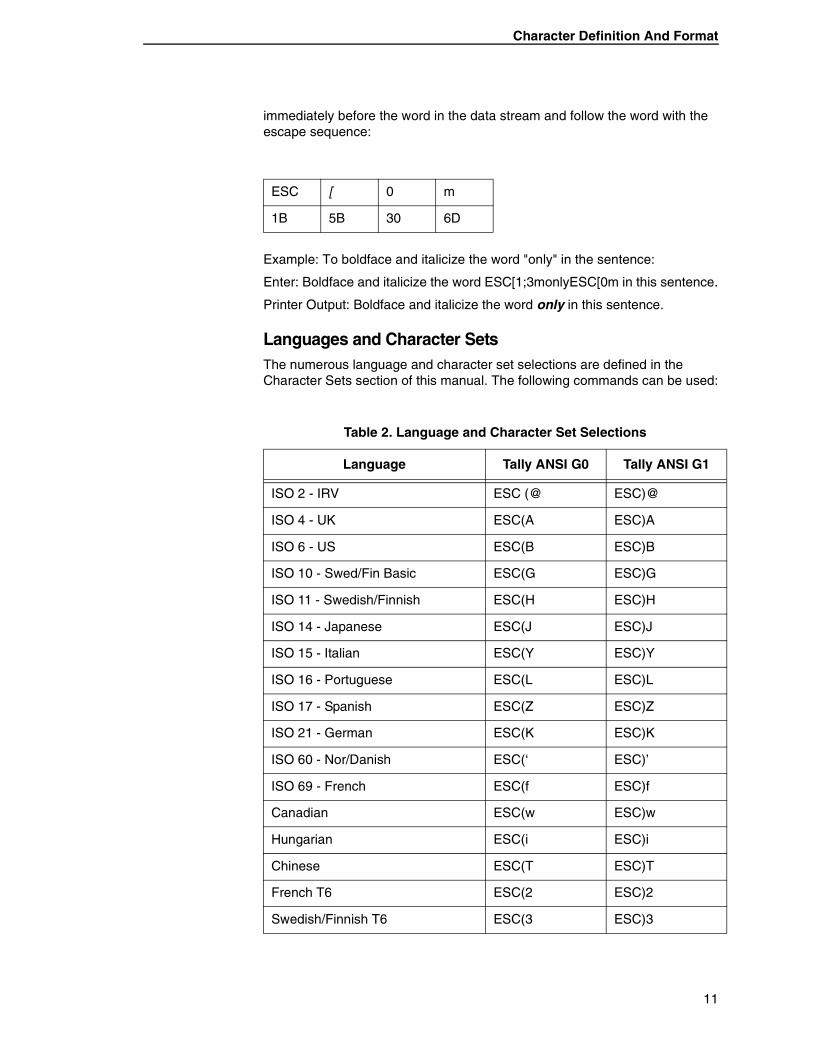
Languages and Character SetsThe numerous language and character set selections are defined in the Character Sets section of this manual. The following commands can be used:
ESC [ 0 m
1B 5B 30 6D
Table 2. Language and Character Set Selections
Language Tally ANSI G0 Tally ANSI G1
ISO 2 - IRV ESC (@ ESC)@
ISO 4 - UK ESC(A ESC)A
ISO 6 - US ESC(B ESC)B
ISO 10 - Swed/Fin Basic ESC(G ESC)G
ISO 11 - Swedish/Finnish ESC(H ESC)H
ISO 14 - Japanese ESC(J ESC)J
ISO 15 - Italian ESC(Y ESC)Y
ISO 16 - Portuguese ESC(L ESC)L
ISO 17 - Spanish ESC(Z ESC)Z
ISO 21 - German ESC(K ESC)K
ISO 60 - Nor/Danish ESC(‘ ESC)’
ISO 69 - French ESC(f ESC)f
Canadian ESC(w ESC)w
Hungarian ESC(i ESC)i
Chinese ESC(T ESC)T
French T6 ESC(2 ESC)2
Swedish/Finnish T6 ESC(3 ESC)3
11
Chapter 1 Tally ANSI
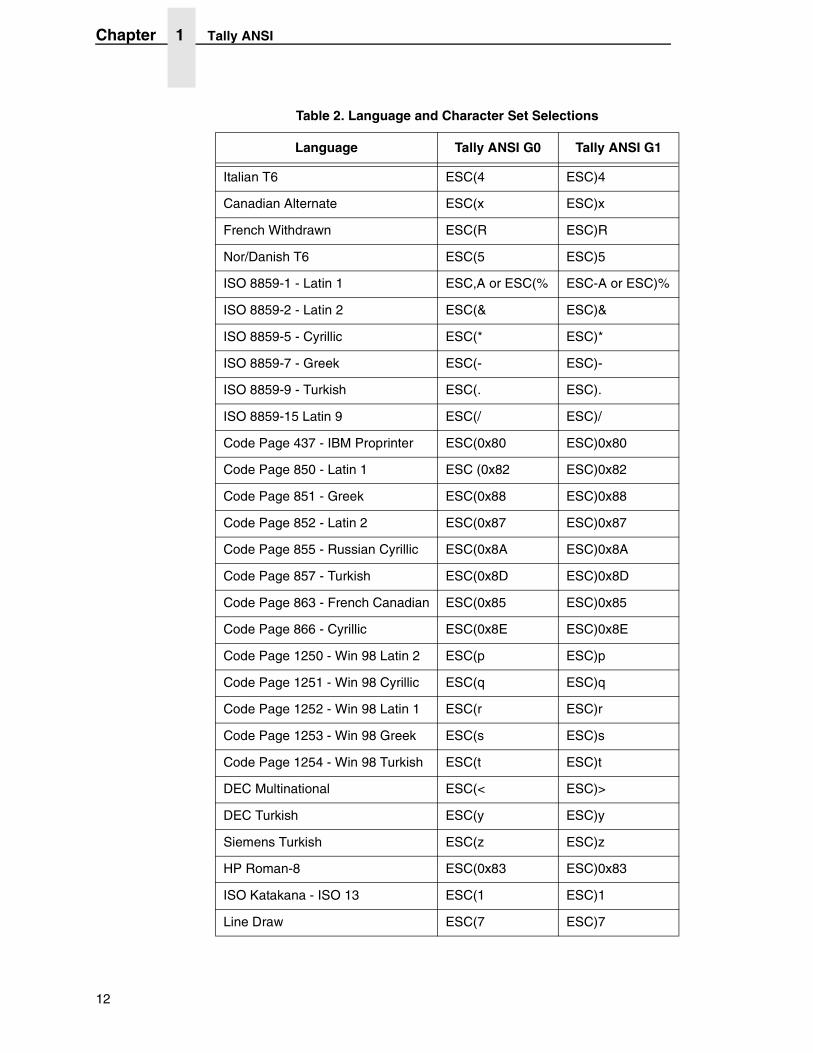
Italian T6 ESC(4 ESC)4
Canadian Alternate ESC(x ESC)x
French Withdrawn ESC(R ESC)R
Nor/Danish T6 ESC(5 ESC)5
ISO 8859-1 - Latin 1 ESC,A or ESC(% ESC-A or ESC)%
ISO 8859-2 - Latin 2 ESC(& ESC)&
ISO 8859-5 - Cyrillic ESC(* ESC)*
ISO 8859-7 - Greek ESC(- ESC)-
ISO 8859-9 - Turkish ESC(. ESC).
ISO 8859-15 Latin 9 ESC(/ ESC)/
Code Page 437 - IBM Proprinter ESC(0x80 ESC)0x80
Code Page 850 - Latin 1 ESC (0x82 ESC)0x82
Code Page 851 - Greek ESC(0x88 ESC)0x88
Code Page 852 - Latin 2 ESC(0x87 ESC)0x87
Code Page 855 - Russian Cyrillic ESC(0x8A ESC)0x8A
Code Page 857 - Turkish ESC(0x8D ESC)0x8D
Code Page 863 - French Canadian ESC(0x85 ESC)0x85
Code Page 866 - Cyrillic ESC(0x8E ESC)0x8E
Code Page 1250 - Win 98 Latin 2 ESC(p ESC)p
Code Page 1251 - Win 98 Cyrillic ESC(q ESC)q
Code Page 1252 - Win 98 Latin 1 ESC(r ESC)r
Code Page 1253 - Win 98 Greek ESC(s ESC)s
Code Page 1254 - Win 98 Turkish ESC(t ESC)t
DEC Multinational ESC(< ESC)>
DEC Turkish ESC(y ESC)y
Siemens Turkish ESC(z ESC)z
HP Roman-8 ESC(0x83 ESC)0x83
ISO Katakana - ISO 13 ESC(1 ESC)1
Line Draw ESC(7 ESC)7
Table 2. Language and Character Set Selections
Language Tally ANSI G0 Tally ANSI G1
12
Character Definition And Format
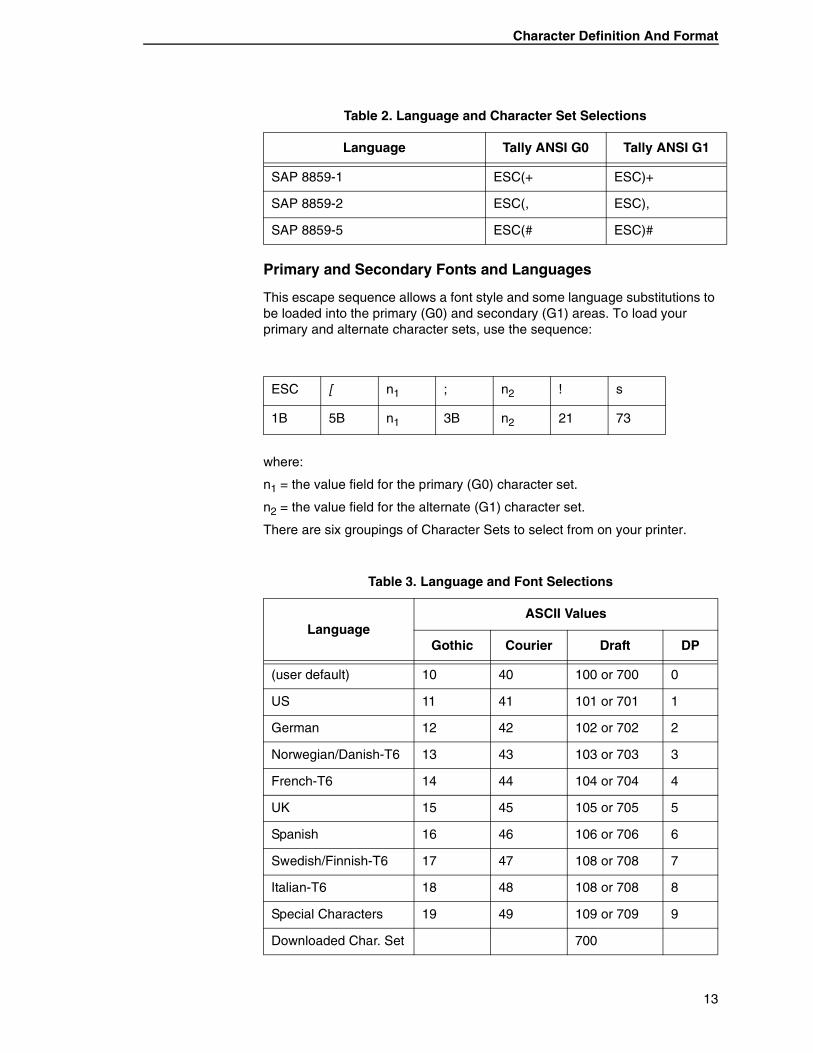
Primary and Secondary Fonts and Languages
This escape sequence allows a font style and some language substitutions to be loaded into the primary (G0) and secondary (G1) areas. To load your primary and alternate character sets, use the sequence:
where:
n1 = the value field for the primary (G0) character set.
n2 = the value field for the alternate (G1) character set.
There are six groupings of Character Sets to select from on your printer.
SAP 8859-1 ESC(+ ESC)+
SAP 8859-2 ESC(, ESC),
SAP 8859-5 ESC(# ESC)#
ESC [ n1 ; n2 ! s
1B 5B n1 3B n2 21 73
Table 3. Language and Font Selections
LanguageASCII Values
Gothic Courier Draft DP
(user default) 10 40 100 or 700 0
US 11 41 101 or 701 1
German 12 42 102 or 702 2
Norwegian/Danish-T6 13 43 103 or 703 3
French-T6 14 44 104 or 704 4
UK 15 45 105 or 705 5
Spanish 16 46 106 or 706 6
Swedish/Finnish-T6 17 47 108 or 708 7
Italian-T6 18 48 108 or 708 8
Special Characters 19 49 109 or 709 9
Downloaded Char. Set 700
Table 2. Language and Character Set Selections
Language Tally ANSI G0 Tally ANSI G1
13
Chapter 1 Tally ANSI
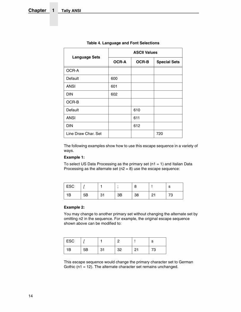
The following examples show how to use this escape sequence in a variety of ways.
Example 1:
To select US Data Processing as the primary set (n1 = 1) and Italian Data Processing as the alternate set (n2 = 8) use the escape sequence:
Example 2:
You may change to another primary set without changing the alternate set by omitting n2 in the sequence. For example, the original escape sequence shown above can be modified to:
This escape sequence would change the primary character set to German Gothic (n1 = 12). The alternate character set remains unchanged.
Table 4. Language and Font Selections
Language SetsASCII Values
OCR-A OCR-B Special Sets
OCR-A
Default 600
ANSI 601
DIN 602
OCR-B
Default 610
ANSI 611
DIN 612
Line Draw Char. Set 720
ESC [ 1 ; 8 ! s
1B 5B 31 3B 38 21 73
ESC [ 1 2 ! s
1B 5B 31 32 21 73
14
Character Definition And Format
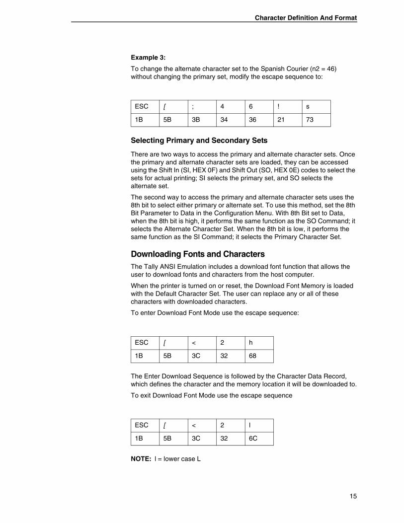
Example 3:
To change the alternate character set to the Spanish Courier (n2 = 46) without changing the primary set, modify the escape sequence to:
Selecting Primary and Secondary Sets
There are two ways to access the primary and alternate character sets. Once the primary and alternate character sets are loaded, they can be accessed using the Shift In (SI, HEX 0F) and Shift Out (SO, HEX 0E) codes to select the sets for actual printing; SI selects the primary set, and SO selects the alternate set.
The second way to access the primary and alternate character sets uses the 8th bit to select either primary or alternate set. To use this method, set the 8th Bit Parameter to Data in the Configuration Menu. With 8th Bit set to Data, when the 8th bit is high, it performs the same function as the SO Command; it selects the Alternate Character Set. When the 8th bit is low, it performs the same function as the SI Command; it selects the Primary Character Set.
Downloading Fonts and CharactersThe Tally ANSI Emulation includes a download font function that allows the user to download fonts and characters from the host computer.
When the printer is turned on or reset, the Download Font Memory is loaded with the Default Character Set. The user can replace any or all of these characters with downloaded characters.
To enter Download Font Mode use the escape sequence:
The Enter Download Sequence is followed by the Character Data Record, which defines the character and the memory location it will be downloaded to.
To exit Download Font Mode use the escape sequence
NOTE: l = lower case L
ESC [ ; 4 6 ! s
1B 5B 3B 34 36 21 73
ESC [ < 2 h
1B 5B 3C 32 68
ESC [ < 2 l
1B 5B 3C 32 6C
15
Chapter 1 Tally ANSI
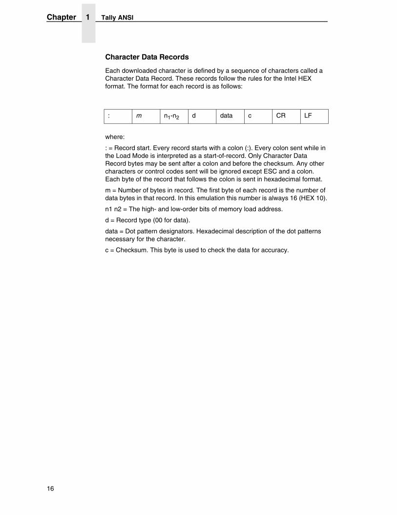
Character Data Records
Each downloaded character is defined by a sequence of characters called a Character Data Record. These records follow the rules for the Intel HEX format. The format for each record is as follows:
where:
: = Record start. Every record starts with a colon (:). Every colon sent while in the Load Mode is interpreted as a start-of-record. Only Character Data Record bytes may be sent after a colon and before the checksum. Any other characters or control codes sent will be ignored except ESC and a colon. Each byte of the record that follows the colon is sent in hexadecimal format.
m = Number of bytes in record. The first byte of each record is the number of data bytes in that record. In this emulation this number is always 16 (HEX 10).
n1 n2 = The high- and low-order bits of memory load address.
d = Record type (00 for data).
data = Dot pattern designators. Hexadecimal description of the dot patterns necessary for the character.
c = Checksum. This byte is used to check the data for accuracy.
: m n1-n2 d data c CR LF
16
Character Definition And Format
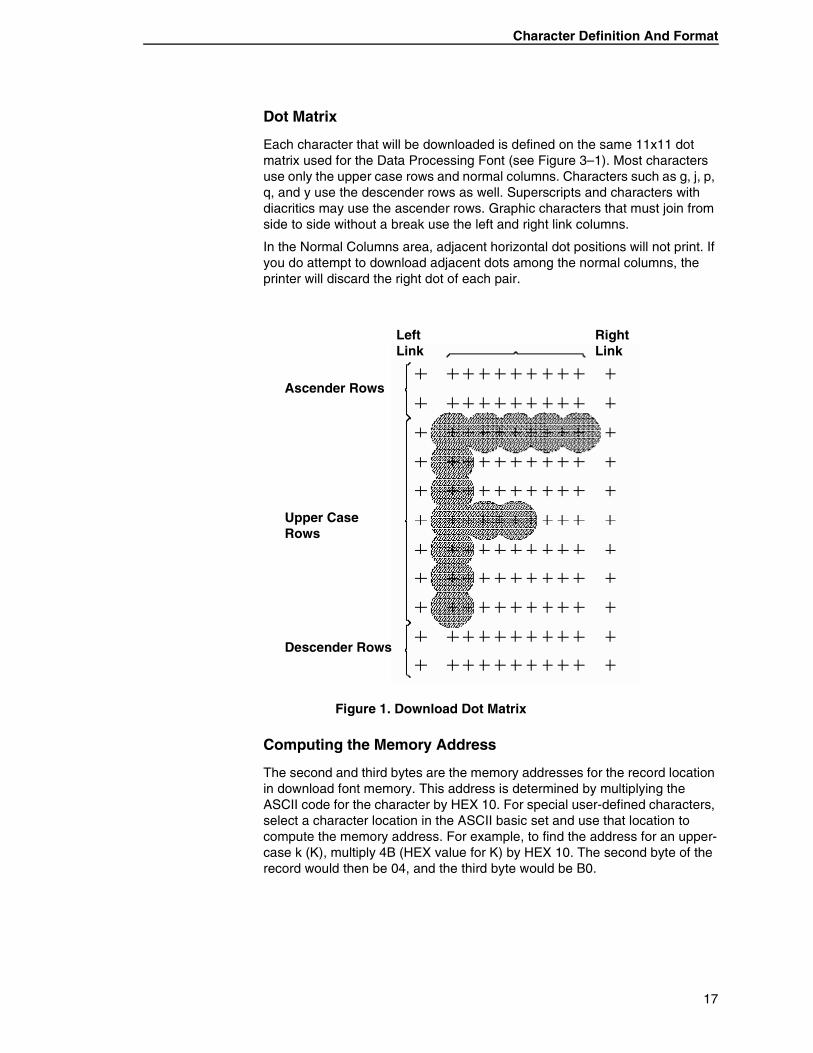
Dot Matrix
Each character that will be downloaded is defined on the same 11x11 dot matrix used for the Data Processing Font (see Figure 3–1). Most characters use only the upper case rows and normal columns. Characters such as g, j, p, q, and y use the descender rows as well. Superscripts and characters with diacritics may use the ascender rows. Graphic characters that must join from side to side without a break use the left and right link columns.
In the Normal Columns area, adjacent horizontal dot positions will not print. If you do attempt to download adjacent dots among the normal columns, the printer will discard the right dot of each pair.
Figure 1. Download Dot Matrix
Computing the Memory Address
The second and third bytes are the memory addresses for the record location in download font memory. This address is determined by multiplying the ASCII code for the character by HEX 10. For special user-defined characters, select a character location in the ASCII basic set and use that location to compute the memory address. For example, to find the address for an upper-case k (K), multiply 4B (HEX value for K) by HEX 10. The second byte of the record would then be 04, and the third byte would be B0.
Right Link
Left Link
Ascender Rows
Upper Case Rows
Descender Rows
17
Chapter 1 Tally ANSI
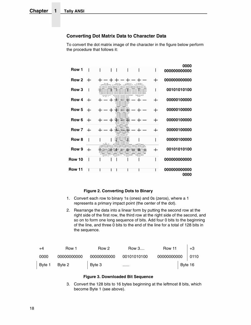
Converting Dot Matrix Data to Character Data
To convert the dot matrix image of the character in the figure below perform the procedure that follows it:
Figure 2. Converting Dots to Binary
1. Convert each row to binary 1s (ones) and 0s (zeros), where a 1 represents a primary impact point (the center of the dot).
2. Rearrange the data into a linear form by putting the second row at the right side of the first row, the third row at the right side of the second, and so on to form one long sequence of bits. Add four 0 bits to the beginning of the line, and three 0 bits to the end of the line for a total of 128 bits in the sequence.
Figure 3. Downloaded Bit Sequence
3. Convert the 128 bits to 16 bytes beginning at the leftmost 8 bits, which become Byte 1 (see above).
Row 1
Row 2
Row 3
Row 4
Row 5
Row 6
Row 7
Row 8
Row 9
Row 10
Row 11
0000 000000000000
000000000000
00101010100
00000100000
00000100000
00000100000
00000100000
00000100000
00101010100
000000000000 0000
000000000000
+4 Row 1 Row 2 Row 3.... Row 11 +3
0000 00000000000 00000000000 00101010100 00000000000 0110
Byte 1 Byte 2 Byte 3 ...... Byte 16
18
Character Definition And Format
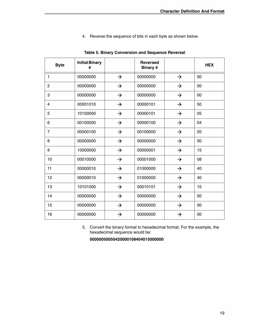
4. Reverse the sequence of bits in each byte as shown below.
5. Convert the binary format to hexadecimal format. For the example, the hexadecimal sequence would be:
00000050050420000108404015000000
Table 5. Binary Conversion and Sequence Reversal
ByteInitial Binary
#Reversed Binary #
HEX
1 00000000 � 00000000 � 00
2 00000000 � 00000000 � 00
3 00000000 � 00000000 � 00
4 00001010 � 00000101 � 50
5 10100000 � 00000101 � 05
6 00100000 � 00000100 � 04
7 00000100 � 00100000 � 20
8 00000000 � 00000000 � 00
9 10000000 � 00000001 � 15
10 00010000 � 00001000 � 08
11 00000010 � 01000000 � 40
12 00000010 � 01000000 � 40
13 10101000 � 00010101 � 15
14 00000000 � 00000000 � 00
15 00000000 � 00000000 � 00
16 00000000 � 00000000 � 00
19
Chapter 1 Tally ANSI
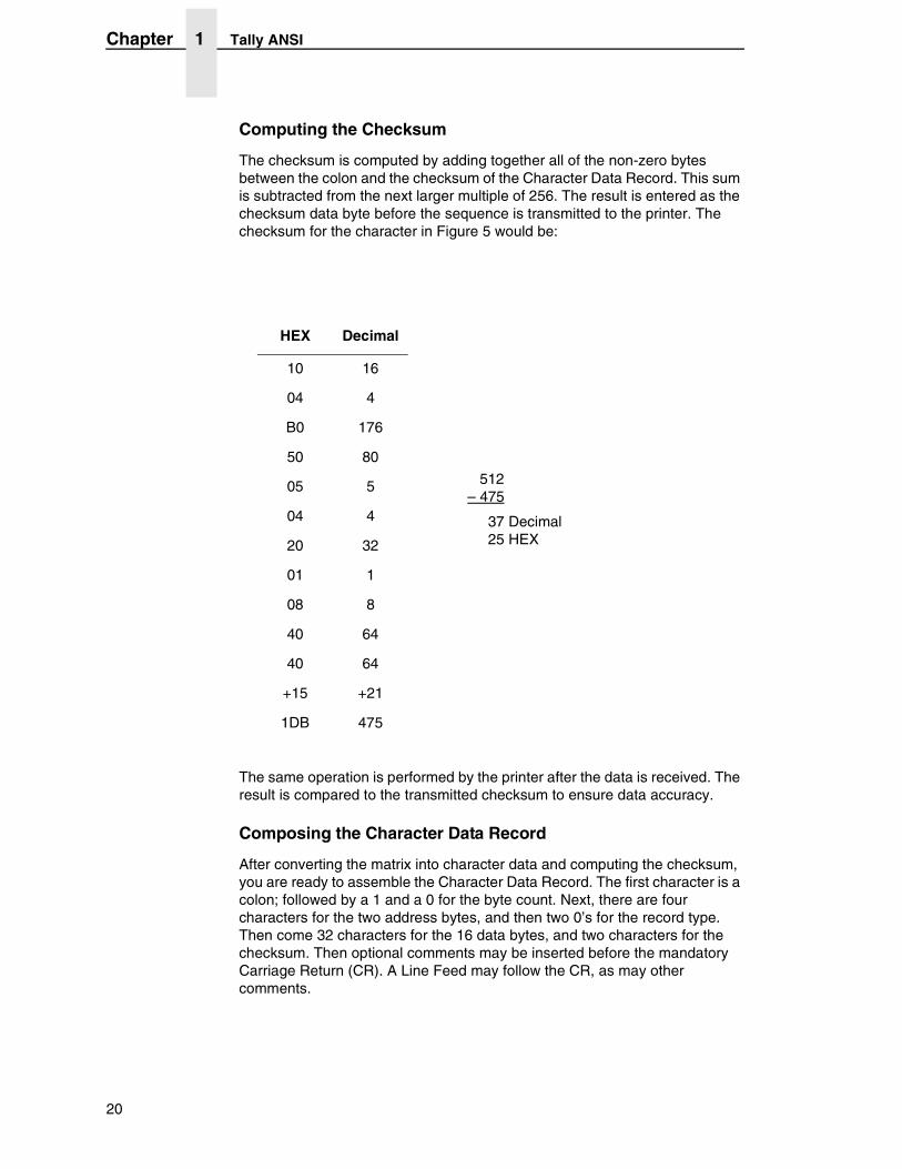
Computing the Checksum
The checksum is computed by adding together all of the non-zero bytes between the colon and the checksum of the Character Data Record. This sum is subtracted from the next larger multiple of 256. The result is entered as the checksum data byte before the sequence is transmitted to the printer. The checksum for the character in Figure 5 would be:
The same operation is performed by the printer after the data is received. The result is compared to the transmitted checksum to ensure data accuracy.
Composing the Character Data Record
After converting the matrix into character data and computing the checksum, you are ready to assemble the Character Data Record. The first character is a colon; followed by a 1 and a 0 for the byte count. Next, there are four characters for the two address bytes, and then two 0’s for the record type. Then come 32 characters for the 16 data bytes, and two characters for the checksum. Then optional comments may be inserted before the mandatory Carriage Return (CR). A Line Feed may follow the CR, as may other comments.
HEX Decimal
10 16
04 4
B0 176
50 80
05 5
04 4
20 32
01 1
08 8
40 64
40 64
+15 +21
1DB 475
512 – 475
37 Decimal 25 HEX
20
Character Definition And Format
Do not include any additional colons.
To load the character into the memory location for the upper-case letter K, the Data Record would be:
:1004B0000000005005042000010840401500000025
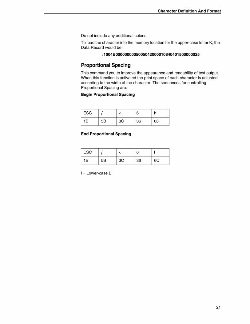
Proportional SpacingThis command you to improve the appearance and readability of text output. When this function is activated the print space of each character is adjusted according to the width of the character. The sequences for controlling Proportional Spacing are:
Begin Proportional Spacing
End Proportional Spacing
l = Lower-case L
ESC [ < 6 h
1B 5B 3C 36 68
ESC [ < 6 l
1B 5B 3C 36 6C
21
Chapter 1 Tally ANSI
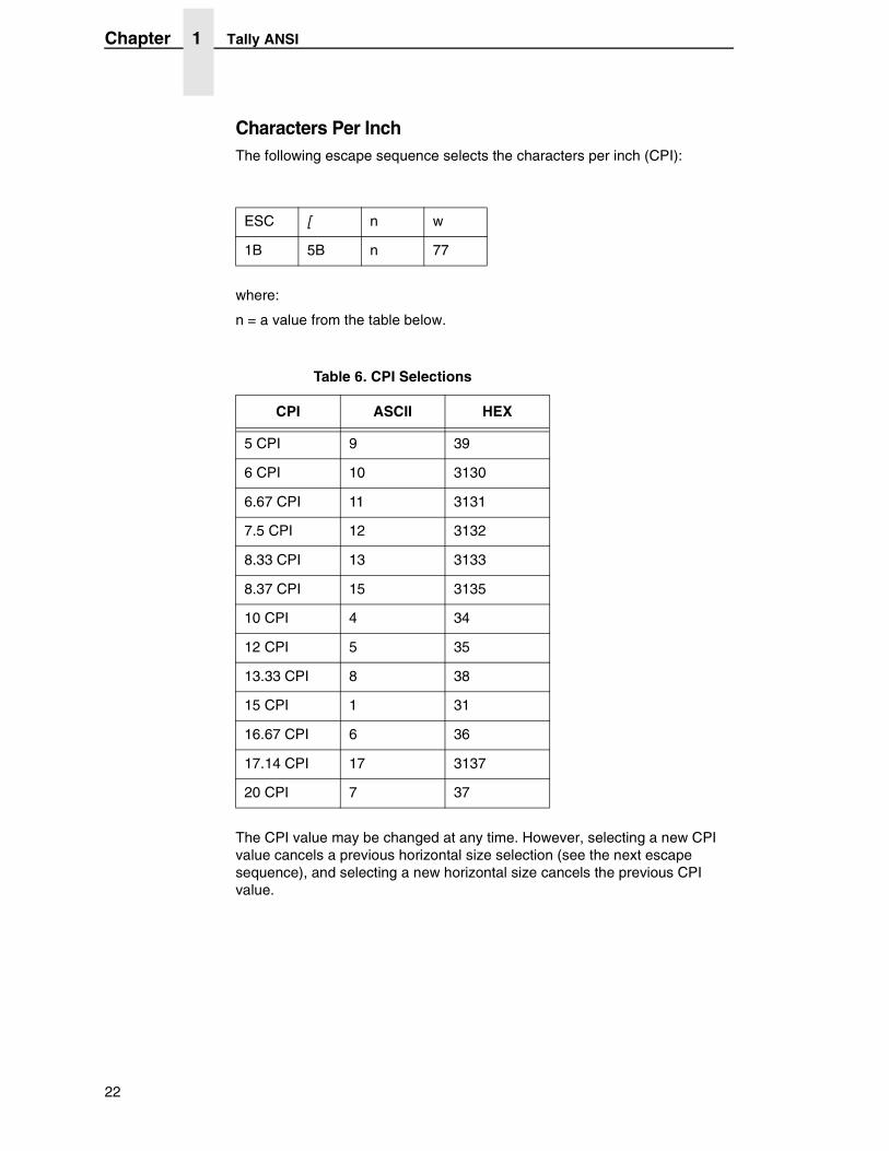
Characters Per InchThe following escape sequence selects the characters per inch (CPI):
where:
n = a value from the table below.
The CPI value may be changed at any time. However, selecting a new CPI value cancels a previous horizontal size selection (see the next escape sequence), and selecting a new horizontal size cancels the previous CPI value.
ESC [ n w
1B 5B n 77
Table 6. CPI Selections
CPI ASCII HEX
5 CPI 9 39
6 CPI 10 3130
6.67 CPI 11 3131
7.5 CPI 12 3132
8.33 CPI 13 3133
8.37 CPI 15 3135
10 CPI 4 34
12 CPI 5 35
13.33 CPI 8 38
15 CPI 1 31
16.67 CPI 6 36
17.14 CPI 17 3137
20 CPI 7 37
22
Character Definition And Format
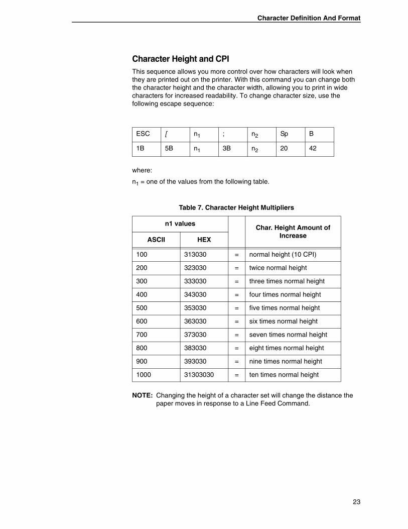
Character Height and CPIThis sequence allows you more control over how characters will look when they are printed out on the printer. With this command you can change both the character height and the character width, allowing you to print in wide characters for increased readability. To change character size, use the following escape sequence:
where:
n1 = one of the values from the following table.
NOTE: Changing the height of a character set will change the distance the paper moves in response to a Line Feed Command.
ESC [ n1 ; n2 Sp B
1B 5B n1 3B n2 20 42
Table 7. Character Height Multipliers
n1 valuesChar. Height Amount of
IncreaseASCII HEX
100 313030 = normal height (10 CPI)
200 323030 = twice normal height
300 333030 = three times normal height
400 343030 = four times normal height
500 353030 = five times normal height
600 363030 = six times normal height
700 373030 = seven times normal height
800 383030 = eight times normal height
900 393030 = nine times normal height
1000 31303030 = ten times normal height
23
Chapter 1 Tally ANSI
where:
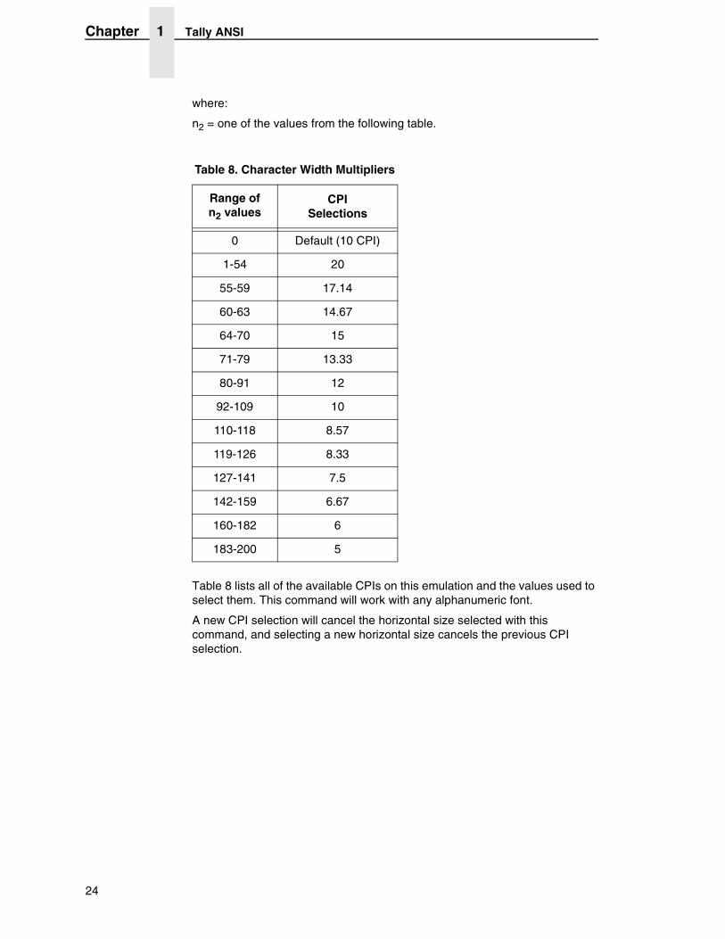
n2 = one of the values from the following table.
Table 8 lists all of the available CPIs on this emulation and the values used to select them. This command will work with any alphanumeric font.
A new CPI selection will cancel the horizontal size selected with this command, and selecting a new horizontal size cancels the previous CPI selection.
Table 8. Character Width Multipliers
Range of n2 values
CPI Selections
0 Default (10 CPI)
1-54 20
55-59 17.14
60-63 14.67
64-70 15
71-79 13.33
80-91 12
92-109 10
110-118 8.57
119-126 8.33
127-141 7.5
142-159 6.67
160-182 6
183-200 5
24
Page Formatting
Page Formatting
Many of the parameters for formatting the print and page characteristics (such as LPI, Horizontal Tabs, etc.) can be set from your host computer using escape sequences. This section discusses and explains the Escape Sequences and Reserved Control Codes used for page formatting.
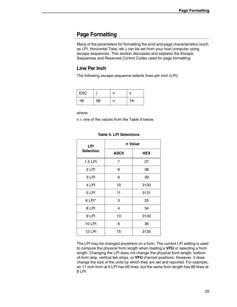
Line Per InchThe following escape sequence selects lines per inch (LPI):
where:
n = one of the values from the Table 9 below.
The LPI may be changed anywhere on a form. The current LPI setting is used to compute the physical form length when loading a VFU or selecting a form length. Changing the LPI does not change the physical form length, bottom-of-form skip, vertical tab stops, or VFU channel positions. However, it does change the size of the units by which they are set and reported. For example, an 11 inch form at 6 LPI has 66 lines, but the same form length has 88 lines at 8 LPI.
ESC [ n z
1B 5B n 7A
Table 9. LPI Selections
LPI Selection
n Value
ASCII HEX
1.5 LPI 7 37
2 LPI 8 38
3 LPI 9 39
4 LPI 10 3130
5 LPI 11 3131
6 LPI* 3 33
8 LPI 4 34
9 LPI 13 3133
10 LPI 6 36
12 LPI 15 3135
25
Chapter 1 Tally ANSI
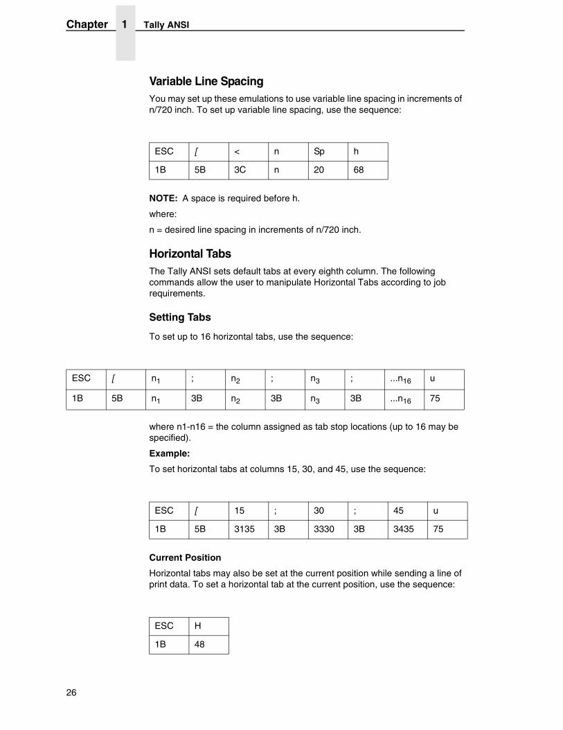
Variable Line SpacingYou may set up these emulations to use variable line spacing in increments of n/720 inch. To set up variable line spacing, use the sequence:
NOTE: A space is required before h.
where:
n = desired line spacing in increments of n/720 inch.
Horizontal TabsThe Tally ANSI sets default tabs at every eighth column. The following commands allow the user to manipulate Horizontal Tabs according to job requirements.
Setting Tabs
To set up to 16 horizontal tabs, use the sequence:
where n1-n16 = the column assigned as tab stop locations (up to 16 may be specified).
Example:
To set horizontal tabs at columns 15, 30, and 45, use the sequence:
Current Position
Horizontal tabs may also be set at the current position while sending a line of print data. To set a horizontal tab at the current position, use the sequence:
ESC [ < n Sp h
1B 5B 3C n 20 68
ESC [ n1 ; n2 ; n3 ; ...n16 u
1B 5B n1 3B n2 3B n3 3B ...n16 75
ESC [ 15 ; 30 ; 45 u
1B 5B 3135 3B 3330 3B 3435 75
ESC H
1B 48
26
Page Formatting
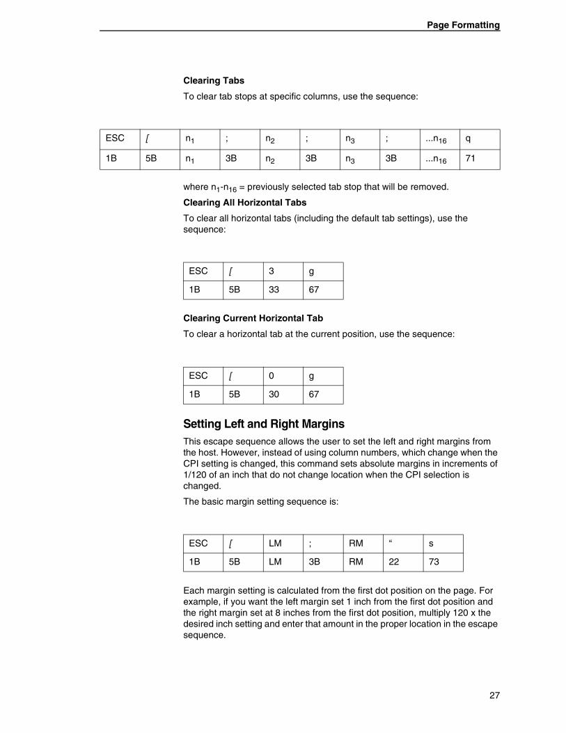
Clearing Tabs
To clear tab stops at specific columns, use the sequence:
where n1-n16 = previously selected tab stop that will be removed.
Clearing All Horizontal Tabs
To clear all horizontal tabs (including the default tab settings), use the sequence:
Clearing Current Horizontal Tab
To clear a horizontal tab at the current position, use the sequence:
Setting Left and Right MarginsThis escape sequence allows the user to set the left and right margins from the host. However, instead of using column numbers, which change when the CPI setting is changed, this command sets absolute margins in increments of 1/120 of an inch that do not change location when the CPI selection is changed.
The basic margin setting sequence is:
Each margin setting is calculated from the first dot position on the page. For example, if you want the left margin set 1 inch from the first dot position and the right margin set at 8 inches from the first dot position, multiply 120 x the desired inch setting and enter that amount in the proper location in the escape sequence.
ESC [ n1 ; n2 ; n3 ; ...n16 q
1B 5B n1 3B n2 3B n3 3B ...n16 71
ESC [ 3 g
1B 5B 33 67
ESC [ 0 g
1B 5B 30 67
ESC [ LM ; RM “ s
1B 5B LM 3B RM 22 73
27
Chapter 1 Tally ANSI
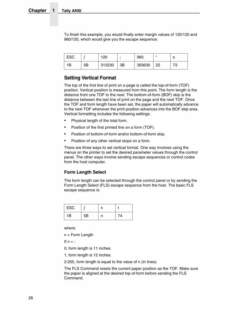
To finish this example, you would finally enter margin values of 120/120 and 960/120, which would give you the escape sequence:
Setting Vertical FormatThe top of the first line of print on a page is called the top-of-form (TOF) position. Vertical position is measured from this point. The form length is the distance from one TOF to the next. The bottom-of-form (BOF) skip is the distance between the last line of print on the page and the next TOF. Once the TOF and form length have been set, the paper will automatically advance to the next TOF whenever the print position advances into the BOF skip area. Vertical formatting includes the following settings:
• Physical length of the total form.
• Position of the first printed line on a form (TOF).
• Position of bottom-of-form and/or bottom-of-form skip.
• Position of any other vertical stops on a form.
There are three ways to set vertical format. One way involves using the menus on the printer to set the desired parameter values through the control panel. The other ways involve sending escape sequences or control codes from the host computer.
Form Length Select
The form length can be selected through the control panel or by sending the Form Length Select (FLS) escape sequence from the host. The basic FLS escape sequence is:
where:
n = Form Length
If n = :
0, form length is 11 inches.
1, form length is 12 inches.
2-255, form length is equal to the value of n (in lines).
The FLS Command resets the current paper position as the TOF. Make sure the paper is aligned at the desired top-of-form before sending the FLS Command.
ESC [ 120 ; 960 “ s
1B 5B 313230 3B 393630 22 73
ESC [ n t
1B 5B n 74
28
Page Formatting
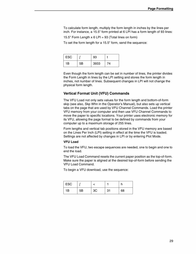
To calculate form length, multiply the form length in inches by the lines per inch. For instance, a 15.5" form printed at 6 LPI has a form length of 93 lines:
15.5" Form Length x 6 LPI = 93 (Total lines on form)
To set the form length for a 15.5" form, send the sequence:
Even though the form length can be set in number of lines, the printer divides the Form Length in lines by the LPI setting and stores the form length in inches, not number of lines. Subsequent changes in LPI will not change the physical form length.
Vertical Format Unit (VFU) Commands
The VFU Load not only sets values for the form length and bottom-of-form skip (see also, Skp Whn in the Operator’s Manual), but also sets up vertical tabs on the page that are used by VFU Channel Commands. Load the printer VFU memory from your computer and then use VFU Channel Commands to move the paper to specific locations. Your printer uses electronic memory for its VFU, allowing the page format to be defined by commands from your computer up to a maximum storage of 255 lines.
Form lengths and vertical tab positions stored in the VFU memory are based on the Lines Per Inch (LPI) setting in effect at the time the VFU is loaded. Settings are not affected by changes in LPI or by entering Plot Mode.
VFU Load
To load the VFU, two escape sequences are needed, one to begin and one to end the load.
The VFU Load Command resets the current paper position as the top-of-form. Make sure the paper is aligned at the desired top-of-form before sending the VFU Load Command.
To begin a VFU download, use the sequence:
ESC [ 93 t
1B 5B 3933 74
ESC [ < 1 h
1B 5B 3C 31 68
29
Chapter 1 Tally ANSI
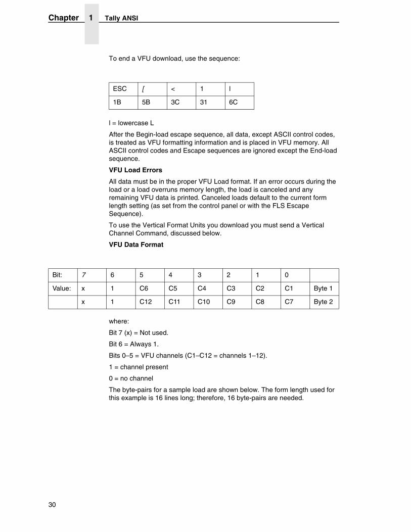
To end a VFU download, use the sequence:
l = lowercase L
After the Begin-load escape sequence, all data, except ASCII control codes, is treated as VFU formatting information and is placed in VFU memory. All ASCII control codes and Escape sequences are ignored except the End-load sequence.
VFU Load Errors
All data must be in the proper VFU Load format. If an error occurs during the load or a load overruns memory length, the load is canceled and any remaining VFU data is printed. Canceled loads default to the current form length setting (as set from the control panel or with the FLS Escape Sequence).
To use the Vertical Format Units you download you must send a Vertical Channel Command, discussed below.
VFU Data Format
where:
Bit 7 (x) = Not used.
Bit 6 = Always 1.
Bits 0–5 = VFU channels (C1–C12 = channels 1–12).
1 = channel present
0 = no channel
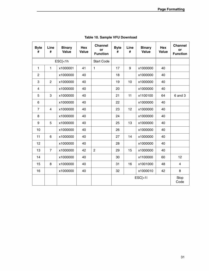
The byte-pairs for a sample load are shown below. The form length used for this example is 16 lines long; therefore, 16 byte-pairs are needed.
ESC [ < 1 l
1B 5B 3C 31 6C
Bit: 7 6 5 4 3 2 1 0
Value: x 1 C6 C5 C4 C3 C2 C1 Byte 1
x 1 C12 C11 C10 C9 C8 C7 Byte 2
30
Page Formatting
Table 10. Sample VFU Download
Byte #
Line #
Binary Value
Hex Value
Channel or
Function
Byte #
Line #
Binary Value
Hex Value
Channel or
Function
ESC[<1h Start Code
1 1 x1000001 41 1 17 9 x1000000 40
2 x1000000 40 18 x1000000 40
3 2 x1000000 40 19 10 x1000000 40
4 x1000000 40 20 x1000000 40
5 3 x1000000 40 21 11 x1100100 64 6 and 3
6 x1000000 40 22 x1000000 40
7 4 x1000000 40 23 12 x1000000 40
8 x1000000 40 24 x1000000 40
9 5 x1000000 40 25 13 x1000000 40
10 x1000000 40 26 x1000000 40
11 6 x1000000 40 27 14 x1000000 40
12 x1000000 40 28 x1000000 40
13 7 x1000000 42 2 29 15 x1000000 40
14 x1000000 40 30 x1100000 60 12
15 8 x1000000 40 31 16 x1001000 48 4
16 x1000000 40 32 x1000010 42 8
ESC[<1| Stop Code
31
Chapter 1 Tally ANSI
Paper And Print Position Movement
There are varieties of commands and escape sequences used to select paper and print movement functions. This section shows both the reserved commands and escape sequences.
When entering or exiting the Character or Plot modes, any data in the print buffer is printed. In Character Mode, the print position moves to the left margin of the current line, or to the current dot row in Plot Mode. If no paper motion command is issued, printing continues at the current print position. The following commands affect print position by moving the paper vertically or print position horizontally or both.
Reserved Control Codes
Horizontal Tab HT 09
This control code moves the print position to the next horizontal tab stop on a line. For multiple tabs, string multiple HT Control Codes together. The printer ignores HT Control Codes if horizontal tabs are not set or if the command is placed in a line beyond the available tabs.
By default, the printer sets a tab stop every 8 columns. These default tab stops can be altered or cleared using the Horizontal Tab Escape Sequence, listed earlier in this chapter.
In the Tally ANSI Emulation, horizontal tab stops change physical location with a change of the left margin or CPI. For example, if a stop is set at column 16, it will always be 15 columns from the left margin, but the physical distance will change for all CPIs.
Form Feed FF 0C
The FF Control Code advances the paper to the first print position of the next form. When Print on Paper Command (POPC) is set to ON, the FF Control Code initiates printing of the preceding buffer contents, then the paper moves to the next TOF.
Vertical Tab VT 0B
When the VFU is enabled, the VT Control Code is used to advance the paper to the next VT Channel location whether the printer is in Character Mode or Plot Mode.
The VT Channel is selected through the printer control panel. If the VFU is not enabled, a VT Command causes a single line feed. If POPC is enabled, the preceding buffer contents are printed before the VT Command is performed.
32
Paper And Print Position Movement
Carriage Return CR 0D
The Carriage Return (CR) Control Code moves the print position back to the left margin. It can be used to overstrike previously printed characters, to print from more than one character set, or to print more than one character size on a single line.
You can overstrike any character to create a special character or symbol, or you can overstrike to create bolder print, underline, etc.
Overstrike is possible only if Auto Line Feed is disabled.
In Automatic Line Feed Mode (Auto LF), when the printer encounters a CR Command, any printable data previously received is printed and the current print position (cursor) moves to the first column of the next line.
Line Feed LF 0A
The Line Feed (LF) Control Code advances the paper one line in Character Mode or one dot-row in Plot Mode.
If the Auto Carriage Return Parameter is set to ON, the printer also moves the print position to the left margin when it receives a Line Feed Command.
If Print on Paper Command (POPC) is enabled, any character data previously received is printed before the move.
• Character Mode
When a LF Command is issued in Character Mode, the actual distance the paper moves in response to a single LF Command depends on the LPI or the Variable Line Spacing setting.
• Plot Mode
When a LF Command is issued in Plot Mode, the actual distance the paper moves depends on the plot density setting for vertical DPI. For example, with a density of 100 dots per inch the paper would advance 1/100 inch, and with a density of 50 dots per inch the paper would advance 1/50 inch.
Save Print PositionThe Save Print Position (SPP) Command saves the current print position into the printer’s memory. The SPP escape sequence is:
ESC P B
1B 50 42
33
Chapter 1 Tally ANSI
Restore Vertical Print PositionThe Restore Vertical Print Position Command moves the paper to the last saved vertical cursor position. If no vertical cursor position has been saved on the current form, the paper moves to the current top-of-form. In either case, the active print position is moved to the left margin. The escape sequence is:
Relative Paper MotionThe Relative Paper Motion (RPM) Command moves the paper forward or backward a requested number of increments from its current print position. Movement distance is dictated by the print mode (Character or Plot). The POPC Parameter dictates whether previous buffer contents are printed when the RPM Command is encountered.
Exceptions:
• Reverse paper motion stops at the Top-Of-Form (TOF) location on the current form.
• Forward motion into a Bottom-Of-Form (BOF) skip area advances the paper to the next TOF, then forward motion continues the remaining number of increments.
The relative paper motion escape sequence is:
where:
c = Paper movement direction.
0 = forward paper motion
9 = reverse paper motion
nn = Number of increments the paper moves.
Range = 1 to 99 ASCII or 31 to 3939 HEX.
Example 1: Moving the paper forward five lines.
ESC P A
1B 50 41
ESC [ c n n ! v
1B 5B c n n 21 76
ESC [ 0 0 5 ! v
1B 5B 30 30 35 21 76
34
Paper And Print Position Movement
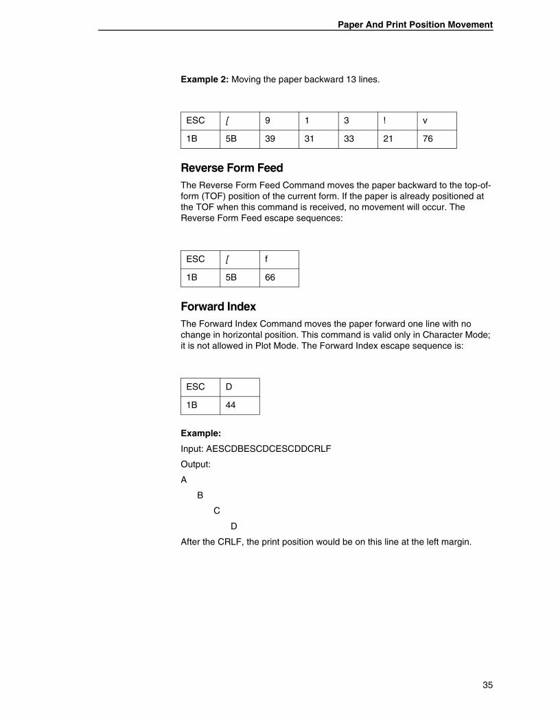
Example 2: Moving the paper backward 13 lines.
Reverse Form FeedThe Reverse Form Feed Command moves the paper backward to the top-of-form (TOF) position of the current form. If the paper is already positioned at the TOF when this command is received, no movement will occur. The Reverse Form Feed escape sequences:
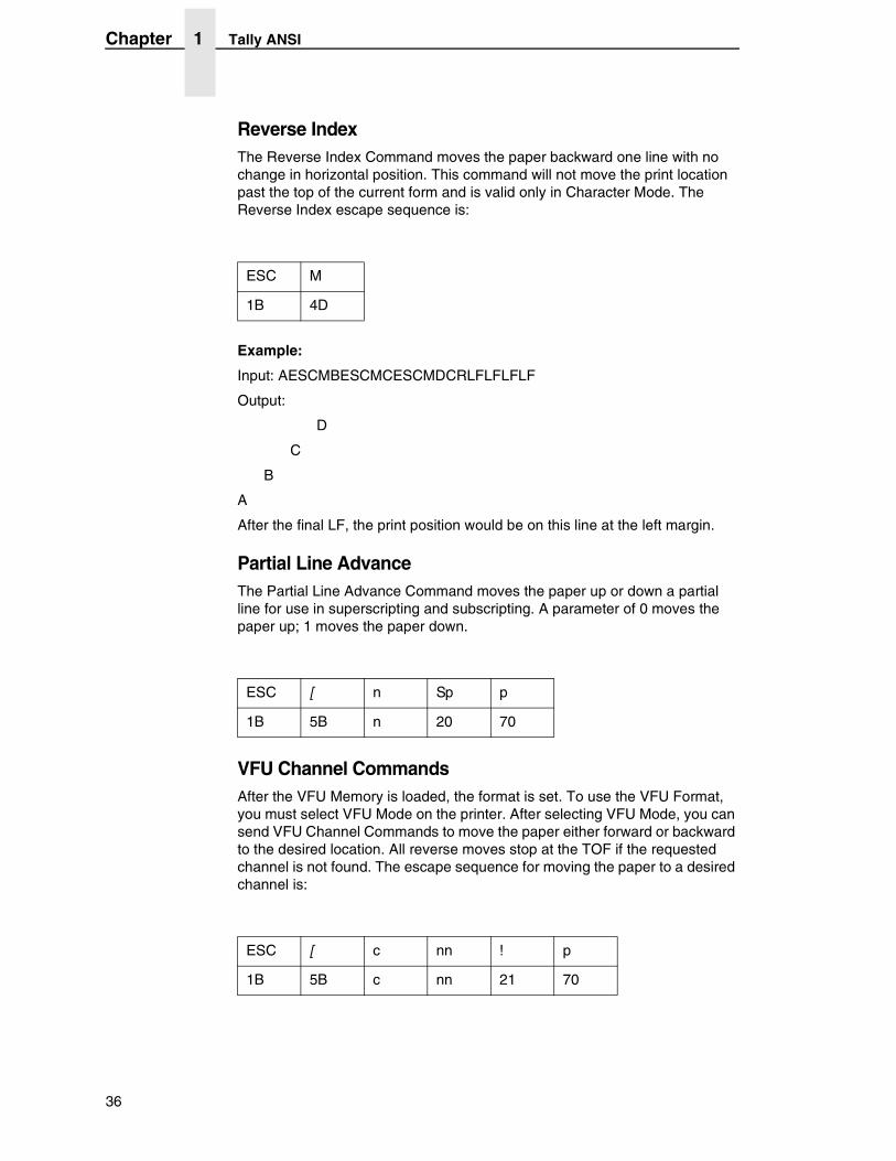
Forward IndexThe Forward Index Command moves the paper forward one line with no change in horizontal position. This command is valid only in Character Mode; it is not allowed in Plot Mode. The Forward Index escape sequence is:
Example:
Input: AESCDBESCDCESCDDCRLF
Output:
A
B
C
D
After the CRLF, the print position would be on this line at the left margin.
ESC [ 9 1 3 ! v
1B 5B 39 31 33 21 76
ESC [ f
1B 5B 66
ESC D
1B 44
35
Chapter 1 Tally ANSI
Reverse IndexThe Reverse Index Command moves the paper backward one line with no change in horizontal position. This command will not move the print location past the top of the current form and is valid only in Character Mode. The Reverse Index escape sequence is:
Example:
Input: AESCMBESCMCESCMDCRLFLFLFLF
Output:
D
C
B
A
After the final LF, the print position would be on this line at the left margin.
Partial Line AdvanceThe Partial Line Advance Command moves the paper up or down a partial line for use in superscripting and subscripting. A parameter of 0 moves the paper up; 1 moves the paper down.
VFU Channel CommandsAfter the VFU Memory is loaded, the format is set. To use the VFU Format, you must select VFU Mode on the printer. After selecting VFU Mode, you can send VFU Channel Commands to move the paper either forward or backward to the desired location. All reverse moves stop at the TOF if the requested channel is not found. The escape sequence for moving the paper to a desired channel is:
ESC M
1B 4D
ESC [ n Sp p
1B 5B n 20 70
ESC [ c nn ! p
1B 5B c nn 21 70
36
Paper And Print Position Movement
where:
c = Paper motion direction.
0 = forward paper motion. 9 = reverse paper motion.
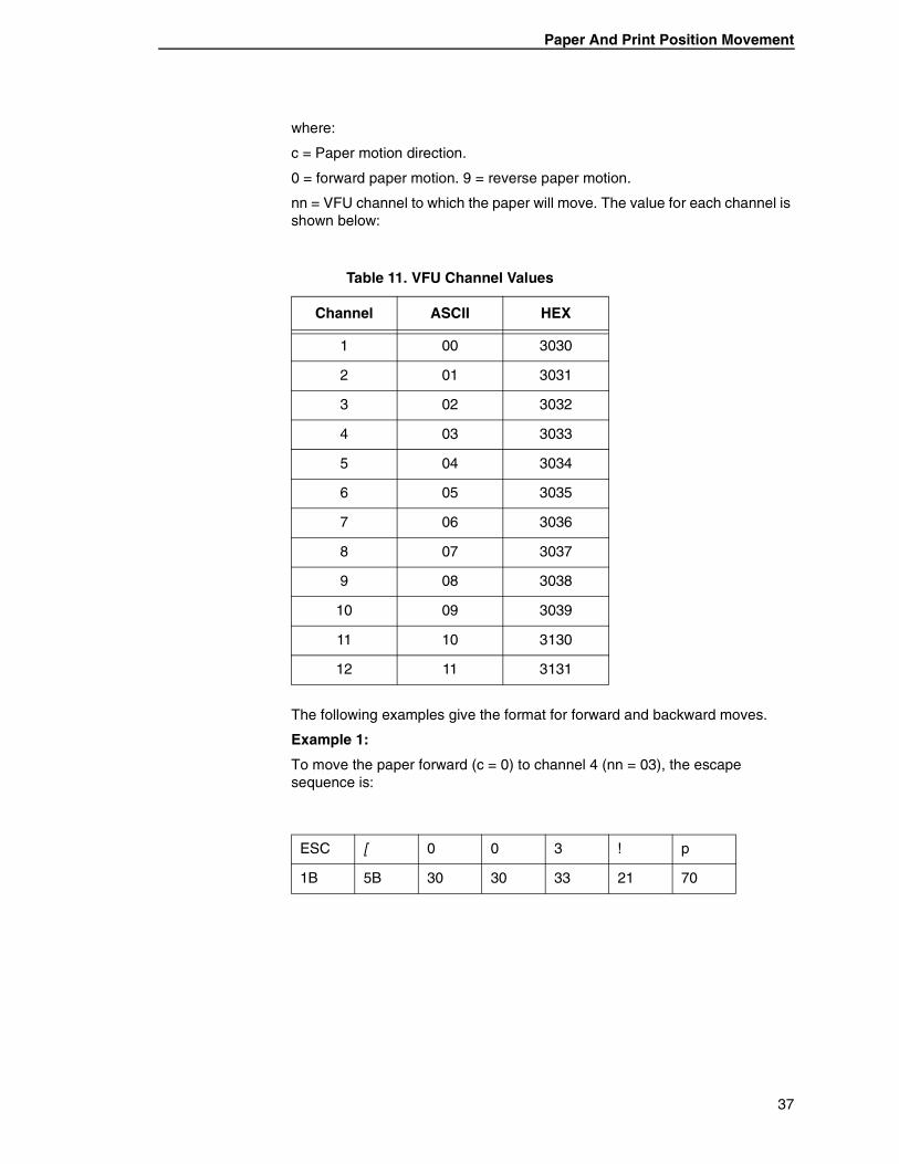
nn = VFU channel to which the paper will move. The value for each channel is shown below:
The following examples give the format for forward and backward moves.
Example 1:
To move the paper forward (c = 0) to channel 4 (nn = 03), the escape sequence is:
Table 11. VFU Channel Values
Channel ASCII HEX
1 00 3030
2 01 3031
3 02 3032
4 03 3033
5 04 3034
6 05 3035
7 06 3036
8 07 3037
9 08 3038
10 09 3039
11 10 3130
12 11 3131
ESC [ 0 0 3 ! p
1B 5B 30 30 33 21 70
37
Chapter 1 Tally ANSI
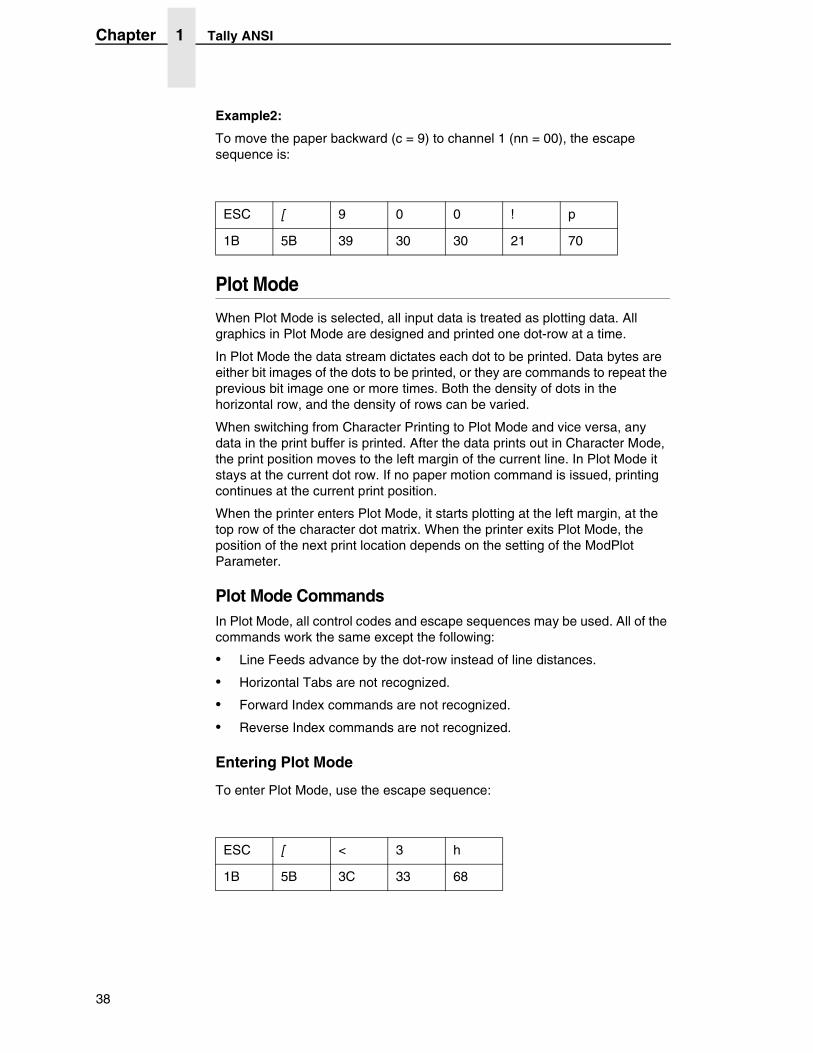
Example2:
To move the paper backward (c = 9) to channel 1 (nn = 00), the escape sequence is:
Plot Mode
When Plot Mode is selected, all input data is treated as plotting data. All graphics in Plot Mode are designed and printed one dot-row at a time.
In Plot Mode the data stream dictates each dot to be printed. Data bytes are either bit images of the dots to be printed, or they are commands to repeat the previous bit image one or more times. Both the density of dots in the horizontal row, and the density of rows can be varied.
When switching from Character Printing to Plot Mode and vice versa, any data in the print buffer is printed. After the data prints out in Character Mode, the print position moves to the left margin of the current line. In Plot Mode it stays at the current dot row. If no paper motion command is issued, printing continues at the current print position.
When the printer enters Plot Mode, it starts plotting at the left margin, at the top row of the character dot matrix. When the printer exits Plot Mode, the position of the next print location depends on the setting of the ModPlot Parameter.
Plot Mode CommandsIn Plot Mode, all control codes and escape sequences may be used. All of the commands work the same except the following:
• Line Feeds advance by the dot-row instead of line distances.
• Horizontal Tabs are not recognized.
• Forward Index commands are not recognized.
• Reverse Index commands are not recognized.
Entering Plot Mode
To enter Plot Mode, use the escape sequence:
ESC [ 9 0 0 ! p
1B 5B 39 30 30 21 70
ESC [ < 3 h
1B 5B 3C 33 68
38
Plot Mode
Exiting Plot Mode
To exit Plot Mode and enter Character Mode, use the escape sequence:
l = lowercase L
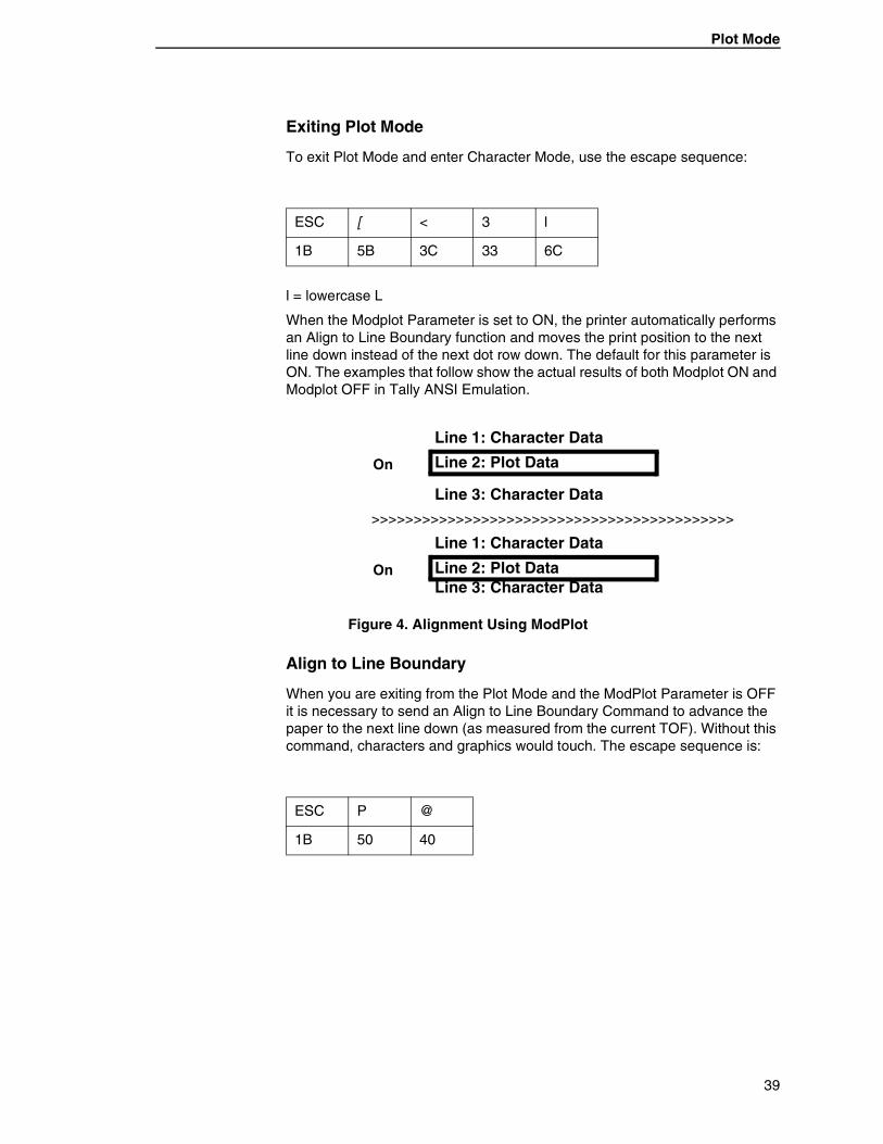
When the Modplot Parameter is set to ON, the printer automatically performs an Align to Line Boundary function and moves the print position to the next line down instead of the next dot row down. The default for this parameter is ON. The examples that follow show the actual results of both Modplot ON and Modplot OFF in Tally ANSI Emulation.
Figure 4. Alignment Using ModPlot
Align to Line Boundary
When you are exiting from the Plot Mode and the ModPlot Parameter is OFF it is necessary to send an Align to Line Boundary Command to advance the paper to the next line down (as measured from the current TOF). Without this command, characters and graphics would touch. The escape sequence is:
ESC [ < 3 l
1B 5B 3C 33 6C
On
Line 1: Character Data
Line 2: Plot Data
Line 3: Character Data
>>>>>>>>>>>>>>>>>>>>>>>>>>>>>>>>>>>>>>>>>>>
On
Line 1: Character Data
Line 2: Plot DataLine 3: Character Data
ESC P @
1B 50 40
39
Chapter 1 Tally ANSI
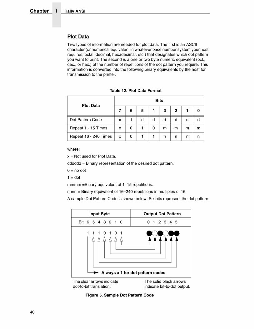
Plot DataTwo types of information are needed for plot data. The first is an ASCII character (or numerical equivalent in whatever base number system your host requires; octal, decimal, hexadecimal, etc.) that designates which dot pattern you want to print. The second is a one or two byte numeric equivalent (oct., dec., or hex.) of the number of repetitions of the dot pattern you require. This information is converted into the following binary equivalents by the host for transmission to the printer.
where:
x = Not used for Plot Data.
dddddd = Binary representation of the desired dot pattern.
0 = no dot
1 = dot
mmmm =Binary equivalent of 1–15 repetitions.
nnnn = Binary equivalent of 16–240 repetitions in multiples of 16.
A sample Dot Pattern Code is shown below. Six bits represent the dot pattern.
Figure 5. Sample Dot Pattern Code
Table 12. Plot Data Format
Plot DataBits
7 6 5 4 3 2 1 0
Dot Pattern Code x 1 d d d d d d
Repeat 1 - 15 Times x 0 1 0 m m m m
Repeat 16 - 240 Times x 0 1 1 n n n n
Bit 6 5 4 3 2 1 0 0 1 2 3 4 5
1 1 1 0 1 0 1
Input Byte Output Dot Pattern
Always a 1 for dot pattern codes
The clear arrows indicate dot-to-bit translation.
The solid black arrows indicate bit-to-dot output.
40
Plot Mode
Plot data is received as binary code that represents the dot pattern to be printed, as shown above. If you do not have a table of the various dot patterns possible with their decimal and hexadecimal equivalents, you can use the following method to compute the numeric equivalents.
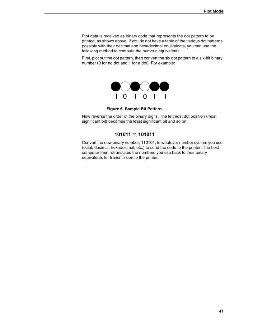
First, plot out the dot pattern, then convert the six dot pattern to a six-bit binary number (0 for no dot and 1 for a dot). For example:
Figure 6. Sample Bit Pattern
Now reverse the order of the binary digits. The leftmost dot position (most significant bit) becomes the least significant bit and so on.
Convert the new binary number, 110101, to whatever number system you use (octal, decimal, hexadecimal, etc.) to send the code to the printer. The host computer then retranslates the numbers you use back to their binary equivalents for transmission to the printer.
1 0 1 1 10
101011 � 101011
41
Chapter 1 Tally ANSI
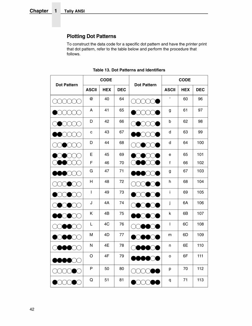
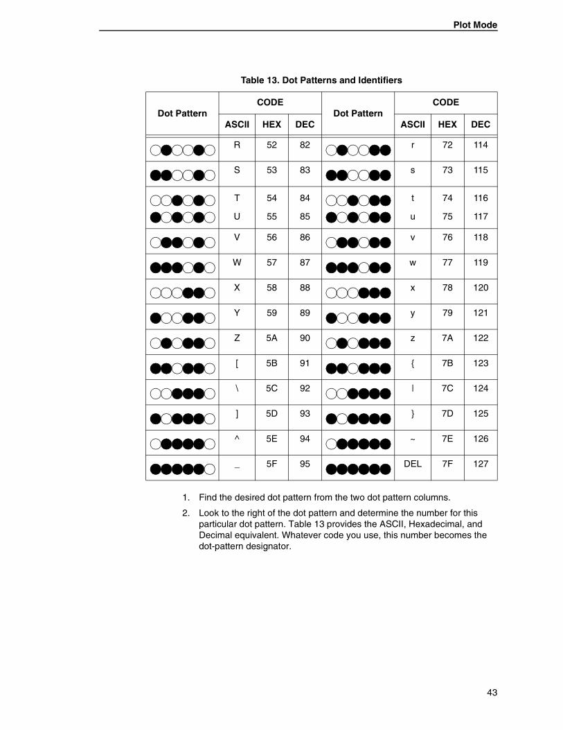
Plotting Dot PatternsTo construct the data code for a specific dot pattern and have the printer print that dot pattern, refer to the table below and perform the procedure that follows.
Table 13. Dot Patterns and Identifiers
Dot PatternCODE
Dot PatternCODE
ASCII HEX DEC ASCII HEX DEC
@ 40 64 ‘ 60 96
A 41 65 g 61 97
D 42 66 b 62 98
c 43 67 d 63 99
D 44 68 d 64 100
E
F
45
46
69
70
e
f
65
66
101
102
G 47 71 g 67 103
H 48 72 h 68 104
I 49 73 i 69 105
J 4A 74 j 6A 106
K 4B 75 k 6B 107
L 4C 76 l 6C 108
M 4D 77 m 6D 109
N 4E 78 n 6E 110
O 4F 79 o 6F 111
P 50 80 p 70 112
Q 51 81 q 71 113
42
Plot Mode
1. Find the desired dot pattern from the two dot pattern columns.
2. Look to the right of the dot pattern and determine the number for this particular dot pattern. Table 13 provides the ASCII, Hexadecimal, and Decimal equivalent. Whatever code you use, this number becomes the dot-pattern designator.
R 52 82 r 72 114
S 53 83 s 73 115
T
U
54
55
84
85
t
u
74
75
116
117
V 56 86 v 76 118
W 57 87 w 77 119
X 58 88 x 78 120
Y 59 89 y 79 121
Z 5A 90 z 7A 122
[ 5B 91 { 7B 123
\ 5C 92 | 7C 124
] 5D 93 } 7D 125
^ 5E 94 ~ 7E 126
_ 5F 95 DEL 7F 127
Table 13. Dot Patterns and Identifiers
Dot PatternCODE
Dot PatternCODE
ASCII HEX DEC ASCII HEX DEC
43
Chapter 1 Tally ANSI
3. Send the Enter Plot Mode escape sequence followed by the dot-pattern designator (ASCII = u), like this:
The desired dot pattern will print one time.
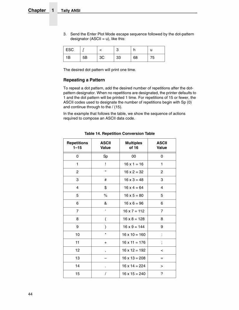
Repeating a Pattern
To repeat a dot pattern, add the desired number of repetitions after the dot-pattern designator. When no repetitions are designated, the printer defaults to 1 and the dot pattern will be printed 1 time. For repetitions of 15 or fewer, the ASCII codes used to designate the number of repetitions begin with Sp (0) and continue through to the / (15).
In the example that follows the table, we show the sequence of actions required to compose an ASCII data code.
ESC [ < 3 h u
1B 5B 3C 33 68 75
Table 14. Repetition Conversion Table
Repetitions1–15
ASCIIValue
Multiplesof 16
ASCIIValue
0 Sp 00 0
1 ! 16 x 1 = 16 1
2 “ 16 x 2 = 32 2
3 # 16 x 3 = 48 3
4 $ 16 x 4 = 64 4
5 % 16 x 5 = 80 5
6 & 16 x 6 = 96 6
7 ‘ 16 x 7 = 112 7
8 ( 16 x 8 = 128 8
9 ) 16 x 9 = 144 9
10 * 16 x 10 = 160 :
11 + 16 x 11 = 176 ;
12 , 16 x 12 = 192 <
13 – 16 x 13 = 208 =
14 . 16 x 14 = 224 >
15 / 16 x 15 = 240 ?
44
Plot Mode
For example, if you wanted to print a pattern 10 times you would look up 10 in the repetition column above; the ASCII character that corresponds to 10 is an asterisk (*). Therefore, placing an asterisk after a dot-pattern designator would cause the printer to repeat the pattern 10 times.
For numbers greater than 15, you must send a two-byte code:
• Byte 1 = (the remainder of the number of desired repetitions) ÷ 16
• Byte 2 = (number of desired repetitions)
— (largest possible multiple of 16 that will result in a positive integer or 0)
The maximum number of times a dot pattern may be repeated per request is 255. The ASCII characters that are used to represent multiples of 16 are 0–? (HEX 30–3F).
Example:
To send 70 repetitions, you must first find the largest multiple of 16 that is less than or equal to 70, then subtract that number from 70 to find the remainder. From the above table you can see that the largest multiple of 16 that is less than or equal to 70 is 64. Subtracting 64 from 70 gives us a result of 6. To find the ASCII equivalent of 6, use Figure 19. To compile the 2-byte code for 70 repetitions, remember, the remainder comes first. The result will be & for the remainder of 6, followed by 4 for the multiple of 16 (64).
Stringing Commands Together
Different dot-pattern designators may be strung together in a single escape sequence to enable printing special graphics. To illustrate stringing designators together, we will use a single dot-pattern command repeated eight times and string together 6 of these commands. That escape sequence is:
Where:
A = The dot pattern.
( = 8 repetitions of the dot pattern. (See Table 13 on page 42).
ESC [ < 3 h u & 4
1B 5B 3C 33 68 75 26 34
ESC[<3h A ( A ( A ( A ( A ( A ( CRLF
1B 41 28 41 28 41 28 41 28 41 28 41 28 0D0A
45
Chapter 1 Tally ANSI
This would result in the selected dot pattern being printed 48 times across the page. Or you may send just a single command that specifies that the selected dot pattern is to be printed 48 times:
The second escape sequence format is more economical and easier to use when stringing commands together, but either of the above commands would result in a horizontal line of 48 dots across the page.
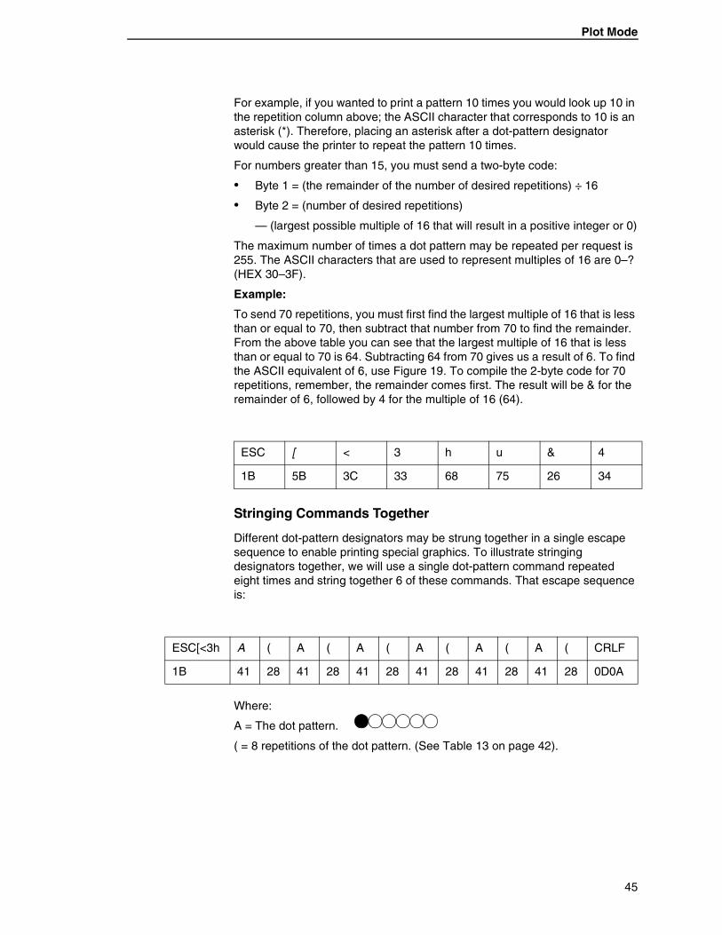
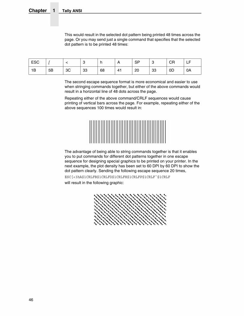
Repeating either of the above command/CRLF sequences would cause printing of vertical bars across the page. For example, repeating either of the above sequences 100 times would result in:
The advantage of being able to string commands together is that it enables you to put commands for different dot patterns together in one escape sequence for designing special graphics to be printed on your printer. In the next example, the plot density has been set to 60 DPI by 60 DPI to show the dot pattern clearly. Sending the following escape sequence 20 times,
ESC[<3hA$1CRLFB$1CRLFD$1CRLFH$1CRLFP$1CRLF`$1CRLF
will result in the following graphic:
ESC [ < 3 h A SP 3 CR LF
1B 5B 3C 33 68 41 20 33 0D 0A
46
Miscellaneous Functions
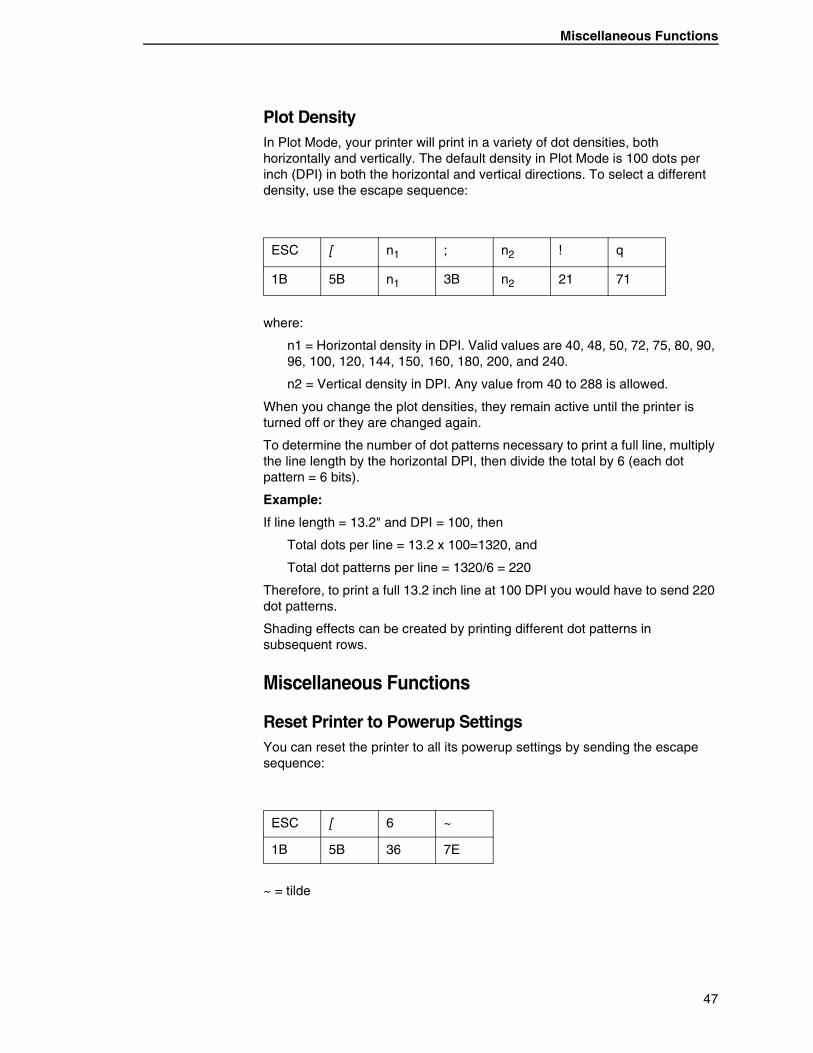
Plot DensityIn Plot Mode, your printer will print in a variety of dot densities, both horizontally and vertically. The default density in Plot Mode is 100 dots per inch (DPI) in both the horizontal and vertical directions. To select a different density, use the escape sequence:
where:
n1 = Horizontal density in DPI. Valid values are 40, 48, 50, 72, 75, 80, 90, 96, 100, 120, 144, 150, 160, 180, 200, and 240.
n2 = Vertical density in DPI. Any value from 40 to 288 is allowed.
When you change the plot densities, they remain active until the printer is turned off or they are changed again.
To determine the number of dot patterns necessary to print a full line, multiply the line length by the horizontal DPI, then divide the total by 6 (each dot pattern = 6 bits).
Example:
If line length = 13.2" and DPI = 100, then
Total dots per line = 13.2 x 100=1320, and
Total dot patterns per line = 1320/6 = 220
Therefore, to print a full 13.2 inch line at 100 DPI you would have to send 220 dot patterns.
Shading effects can be created by printing different dot patterns in subsequent rows.
Miscellaneous Functions
Reset Printer to Powerup SettingsYou can reset the printer to all its powerup settings by sending the escape sequence:
~ = tilde
ESC [ n1 ; n2 ! q
1B 5B n1 3B n2 21 71
ESC [ 6 ~
1B 5B 36 7E
47
Chapter 1 Tally ANSI
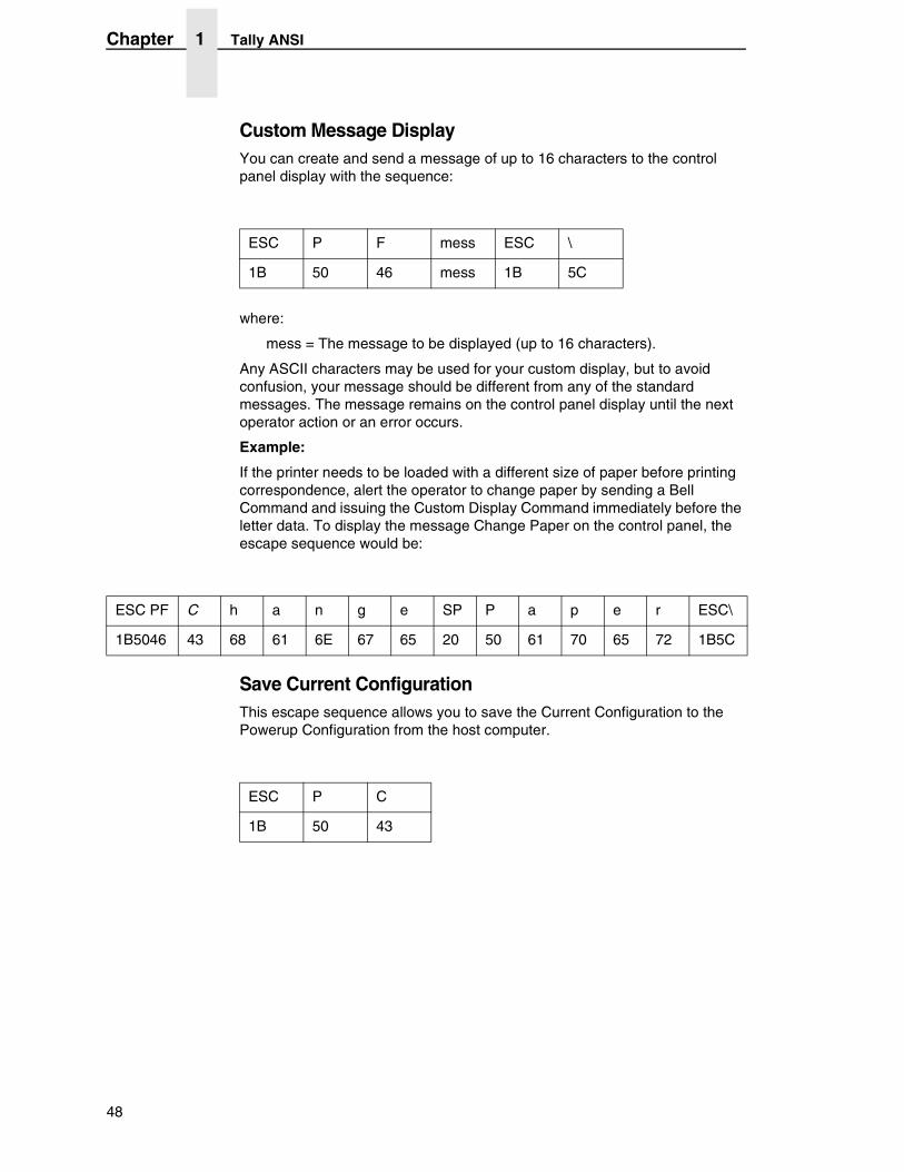
Custom Message DisplayYou can create and send a message of up to 16 characters to the control panel display with the sequence:
where:
mess = The message to be displayed (up to 16 characters).
Any ASCII characters may be used for your custom display, but to avoid confusion, your message should be different from any of the standard messages. The message remains on the control panel display until the next operator action or an error occurs.
Example:
If the printer needs to be loaded with a different size of paper before printing correspondence, alert the operator to change paper by sending a Bell Command and issuing the Custom Display Command immediately before the letter data. To display the message Change Paper on the control panel, the escape sequence would be:
Save Current ConfigurationThis escape sequence allows you to save the Current Configuration to the Powerup Configuration from the host computer.
ESC P F mess ESC \
1B 50 46 mess 1B 5C
ESC PF C h a n g e SP P a p e r ESC\
1B5046 43 68 61 6E 67 65 20 50 61 70 65 72 1B5C
ESC P C
1B 50 43
48
Miscellaneous Functions
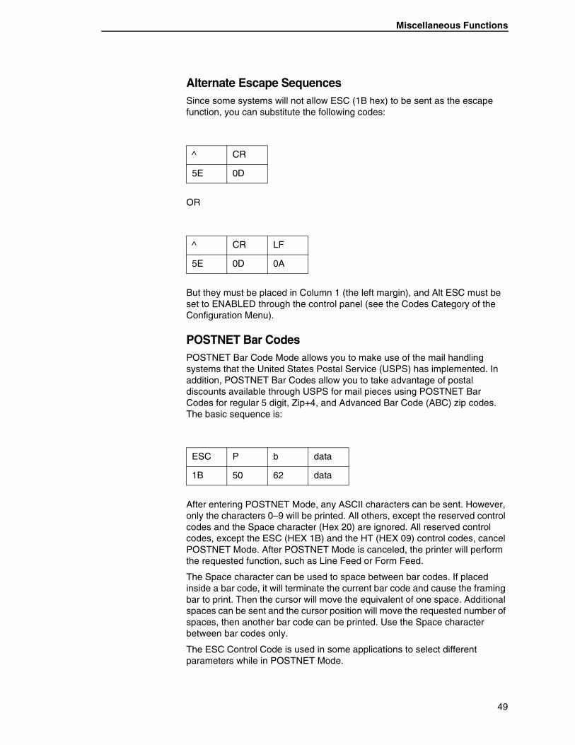
Alternate Escape SequencesSince some systems will not allow ESC (1B hex) to be sent as the escape function, you can substitute the following codes:
OR
But they must be placed in Column 1 (the left margin), and Alt ESC must be set to ENABLED through the control panel (see the Codes Category of the Configuration Menu).
POSTNET Bar CodesPOSTNET Bar Code Mode allows you to make use of the mail handling systems that the United States Postal Service (USPS) has implemented. In addition, POSTNET Bar Codes allow you to take advantage of postal discounts available through USPS for mail pieces using POSTNET Bar Codes for regular 5 digit, Zip+4, and Advanced Bar Code (ABC) zip codes. The basic sequence is:
After entering POSTNET Mode, any ASCII characters can be sent. However, only the characters 0–9 will be printed. All others, except the reserved control codes and the Space character (Hex 20) are ignored. All reserved control codes, except the ESC (HEX 1B) and the HT (HEX 09) control codes, cancel POSTNET Mode. After POSTNET Mode is canceled, the printer will perform the requested function, such as Line Feed or Form Feed.
The Space character can be used to space between bar codes. If placed inside a bar code, it will terminate the current bar code and cause the framing bar to print. Then the cursor will move the equivalent of one space. Additional spaces can be sent and the cursor position will move the requested number of spaces, then another bar code can be printed. Use the Space character between bar codes only.
The ESC Control Code is used in some applications to select different parameters while in POSTNET Mode.
^ CR
5E 0D
^ CR LF
5E 0D 0A
ESC P b data
1B 50 62 data
49
Chapter 1 Tally ANSI
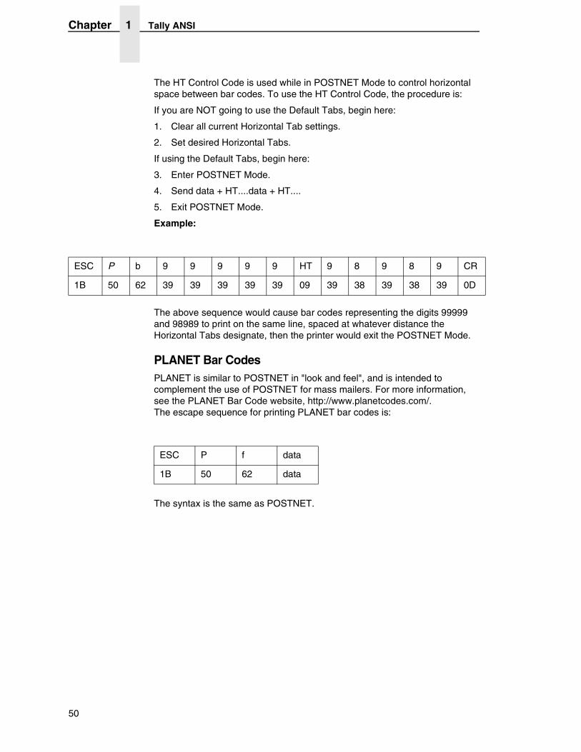
The HT Control Code is used while in POSTNET Mode to control horizontal space between bar codes. To use the HT Control Code, the procedure is:
If you are NOT going to use the Default Tabs, begin here:
1. Clear all current Horizontal Tab settings.
2. Set desired Horizontal Tabs.
If using the Default Tabs, begin here:
3. Enter POSTNET Mode.
4. Send data + HT....data + HT....
5. Exit POSTNET Mode.
Example:
The above sequence would cause bar codes representing the digits 99999 and 98989 to print on the same line, spaced at whatever distance the Horizontal Tabs designate, then the printer would exit the POSTNET Mode.
PLANET Bar CodesPLANET is similar to POSTNET in "look and feel", and is intended to complement the use of POSTNET for mass mailers. For more information, see the PLANET Bar Code website, http://www.planetcodes.com/. The escape sequence for printing PLANET bar codes is:
The syntax is the same as POSTNET.
ESC P b 9 9 9 9 9 HT 9 8 9 8 9 CR
1B 50 62 39 39 39 39 39 09 39 38 39 38 39 0D
ESC P f data
1B 50 62 data
50
Miscellaneous Functions
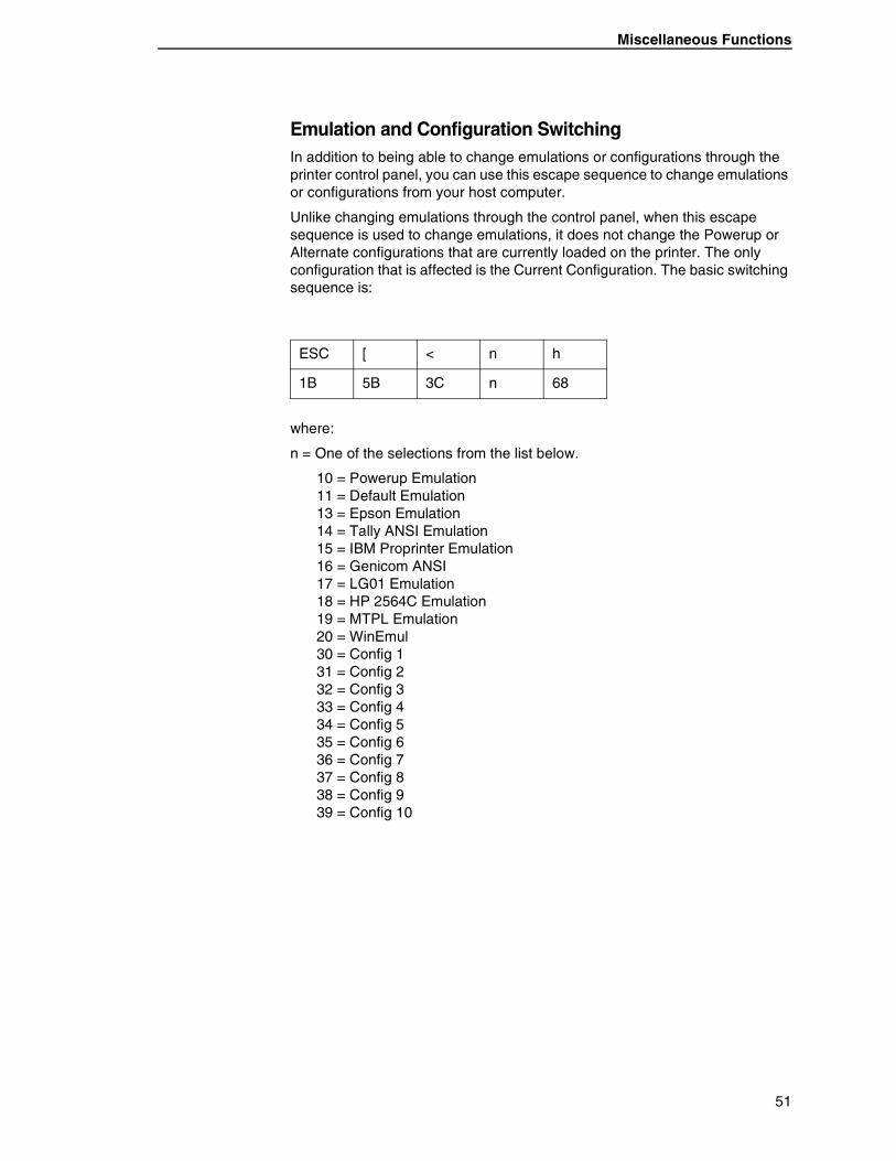
Emulation and Configuration SwitchingIn addition to being able to change emulations or configurations through the printer control panel, you can use this escape sequence to change emulations or configurations from your host computer.
Unlike changing emulations through the control panel, when this escape sequence is used to change emulations, it does not change the Powerup or Alternate configurations that are currently loaded on the printer. The only configuration that is affected is the Current Configuration. The basic switching sequence is:
where:
n = One of the selections from the list below.
10 = Powerup Emulation 11 = Default Emulation 13 = Epson Emulation 14 = Tally ANSI Emulation 15 = IBM Proprinter Emulation 16 = Genicom ANSI 17 = LG01 Emulation 18 = HP 2564C Emulation 19 = MTPL Emulation 20 = WinEmul 30 = Config 1 31 = Config 2 32 = Config 3 33 = Config 4 34 = Config 5 35 = Config 6 36 = Config 7 37 = Config 8 38 = Config 9 39 = Config 10
ESC [ < n h
1B 5B 3C n 68
51
Chapter 1 Tally ANSI
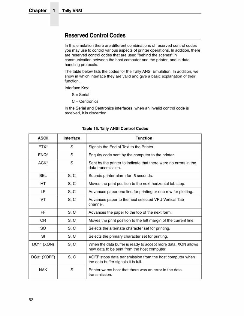
Reserved Control Codes
In this emulation there are different combinations of reserved control codes you may use to control various aspects of printer operations. In addition, there are reserved control codes that are used "behind the scenes" in communication between the host computer and the printer, and in data handling protocols.
The table below lists the codes for the Tally ANSI Emulation. In addition, we show in which interface they are valid and give a basic explanation of their function.
Interface Key:
S = Serial
C = Centronics
In the Serial and Centronics interfaces, when an invalid control code is received, it is discarded.
Table 15. Tally ANSI Control Codes
ASCII Interface Function
ETX* S Signals the End of Text to the Printer.
ENQ* S Enquiry code sent by the computer to the printer.
ACK* S Sent by the printer to indicate that there were no errors in the data transmission.
BEL S, C Sounds printer alarm for .5 seconds.
HT S, C Moves the print position to the next horizontal tab stop.
LF S, C Advances paper one line for printing or one row for plotting.
VT S, C Advances paper to the next selected VFU Vertical Tab channel.
FF S, C Advances the paper to the top of the next form.
CR S, C Moves the print position to the left margin of the current line.
SO S, C Selects the alternate character set for printing.
SI S, C Selects the primary character set for printing.
DC1* (XON) S, C When the data buffer is ready to accept more data, XON allows new data to be sent from the host computer.
DC3* (XOFF) S, C XOFF stops data transmission from the host computer when the data buffer signals it is full.
NAK S Printer warns host that there was an error in the data transmission.
52
Escape Sequence Summary
Escape Sequence Summary
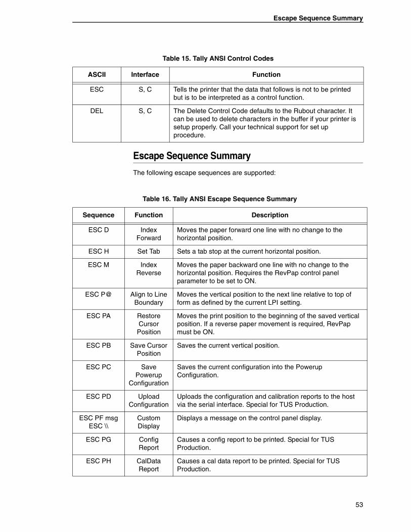
The following escape sequences are supported:
ESC S, C Tells the printer that the data that follows is not to be printed but is to be interpreted as a control function.
DEL S, C The Delete Control Code defaults to the Rubout character. It can be used to delete characters in the buffer if your printer is setup properly. Call your technical support for set up procedure.
Table 15. Tally ANSI Control Codes
ASCII Interface Function
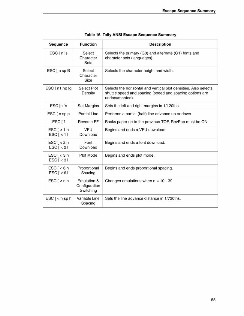
Table 16. Tally ANSI Escape Sequence Summary
Sequence Function Description
ESC D Index Forward
Moves the paper forward one line with no change to the horizontal position.
ESC H Set Tab Sets a tab stop at the current horizontal position.
ESC M Index Reverse
Moves the paper backward one line with no change to the horizontal position. Requires the RevPap control panel parameter to be set to ON.
ESC P@ Align to Line Boundary
Moves the vertical position to the next line relative to top of form as defined by the current LPI setting.
ESC PA Restore Cursor Position
Moves the print position to the beginning of the saved vertical position. If a reverse paper movement is required, RevPap must be ON.
ESC PB Save Cursor Position
Saves the current vertical position.
ESC PC Save Powerup
Configuration
Saves the current configuration into the Powerup Configuration.
ESC PD Upload Configuration
Uploads the configuration and calibration reports to the host via the serial interface. Special for TUS Production.
ESC PF msg ESC \\
Custom Display
Displays a message on the control panel display.
ESC PG Config Report
Causes a config report to be printed. Special for TUS Production.
ESC PH CalData Report
Causes a cal data report to be printed. Special for TUS Production.
53
Chapter 1 Tally ANSI
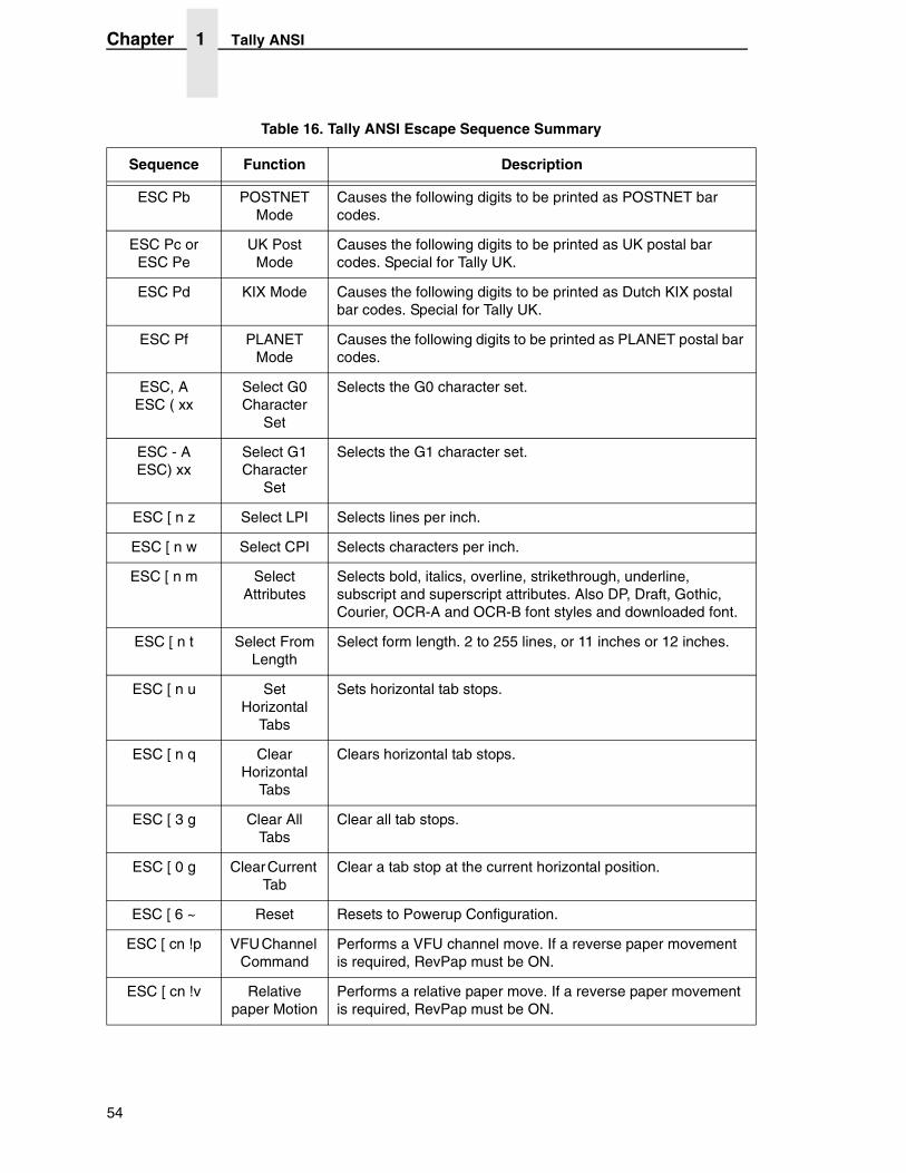
ESC Pb POSTNET Mode
Causes the following digits to be printed as POSTNET bar codes.
ESC Pc or ESC Pe
UK Post Mode
Causes the following digits to be printed as UK postal bar codes. Special for Tally UK.
ESC Pd KIX Mode Causes the following digits to be printed as Dutch KIX postal bar codes. Special for Tally UK.
ESC Pf PLANET Mode
Causes the following digits to be printed as PLANET postal bar codes.
ESC, A ESC ( xx
Select G0Character
Set
Selects the G0 character set.
ESC - AESC) xx
Select G1Character
Set
Selects the G1 character set.
ESC [ n z Select LPI Selects lines per inch.
ESC [ n w Select CPI Selects characters per inch.
ESC [ n m Select Attributes
Selects bold, italics, overline, strikethrough, underline, subscript and superscript attributes. Also DP, Draft, Gothic, Courier, OCR-A and OCR-B font styles and downloaded font.
ESC [ n t Select From Length
Select form length. 2 to 255 lines, or 11 inches or 12 inches.
ESC [ n u Set Horizontal
Tabs
Sets horizontal tab stops.
ESC [ n q Clear Horizontal
Tabs
Clears horizontal tab stops.
ESC [ 3 g Clear All Tabs
Clear all tab stops.
ESC [ 0 g Clear Current Tab
Clear a tab stop at the current horizontal position.
ESC [ 6 ~ Reset Resets to Powerup Configuration.
ESC [ cn !p VFU Channel Command
Performs a VFU channel move. If a reverse paper movement is required, RevPap must be ON.
ESC [ cn !v Relative paper Motion
Performs a relative paper move. If a reverse paper movement is required, RevPap must be ON.
Table 16. Tally ANSI Escape Sequence Summary
Sequence Function Description
54
Escape Sequence Summary
ESC [ n !s Select Character
Sets
Selects the primary (G0) and alternate (G1) fonts and character sets (languages).
ESC [ n sp B Select Character
Size
Selects the character height and width.
ESC [ n1;n2 !q Select Plot Density
Selects the horizontal and vertical plot densities. Also selects shuttle speed and spacing (speed and spacing options are undocumented).
ESC [n “s Set Margins Sets the left and right margins in 1/120ths.
ESC [ n sp p Partial Line Performs a partial (half) line advance up or down.
ESC [ f Reverse FF Backs paper up to the previous TOF. RevPap must be ON.
ESC [ < 1 hESC [ < 1 l
VFUDownload
Begins and ends a VFU download.
ESC [ < 2 hESC [ < 2 l
FontDownload
Begins and ends a font download.
ESC [ < 3 hESC [ < 3 l
Plot Mode Begins and ends plot mode.
ESC [ < 6 hESC [ < 6 l
Proportional Spacing
Begins and ends proportional spacing.
ESC [ < n h Emulation & Configuration
Switching
Changes emulations when n = 10 - 39
ESC [ < n sp h Variable Line Spacing
Sets the line advance distance in 1/720ths.
Table 16. Tally ANSI Escape Sequence Summary
Sequence Function Description
55
Chapter 1 Genicom ANSI
Genicom ANSI
Emulation Definition
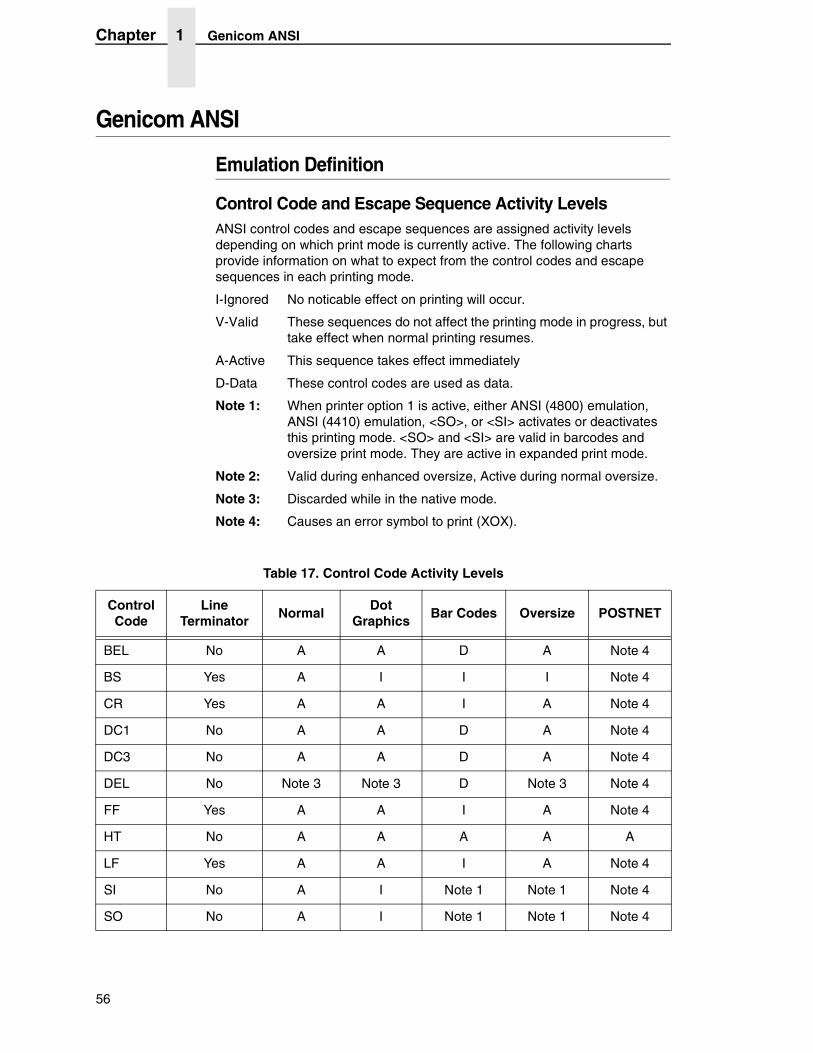
Control Code and Escape Sequence Activity LevelsANSI control codes and escape sequences are assigned activity levels depending on which print mode is currently active. The following charts provide information on what to expect from the control codes and escape sequences in each printing mode.
I-Ignored No noticable effect on printing will occur.
V-Valid These sequences do not affect the printing mode in progress, but take effect when normal printing resumes.
A-Active This sequence takes effect immediately
D-Data These control codes are used as data.
Note 1: When printer option 1 is active, either ANSI (4800) emulation, ANSI (4410) emulation, <SO>, or <SI> activates or deactivates this printing mode. <SO> and <SI> are valid in barcodes and oversize print mode. They are active in expanded print mode.
Note 2: Valid during enhanced oversize, Active during normal oversize.
Note 3: Discarded while in the native mode.
Note 4: Causes an error symbol to print (XOX).
Table 17. Control Code Activity Levels
Control Code
Line Terminator
NormalDot
GraphicsBar Codes Oversize POSTNET
BEL No A A D A Note 4
BS Yes A I I I Note 4
CR Yes A A I A Note 4
DC1 No A A D A Note 4
DC3 No A A D A Note 4
DEL No Note 3 Note 3 D Note 3 Note 4
FF Yes A A I A Note 4
HT No A A A A A
LF Yes A A I A Note 4
SI No A I Note 1 Note 1 Note 4
SO No A I Note 1 Note 1 Note 4
56
Emulation Definition
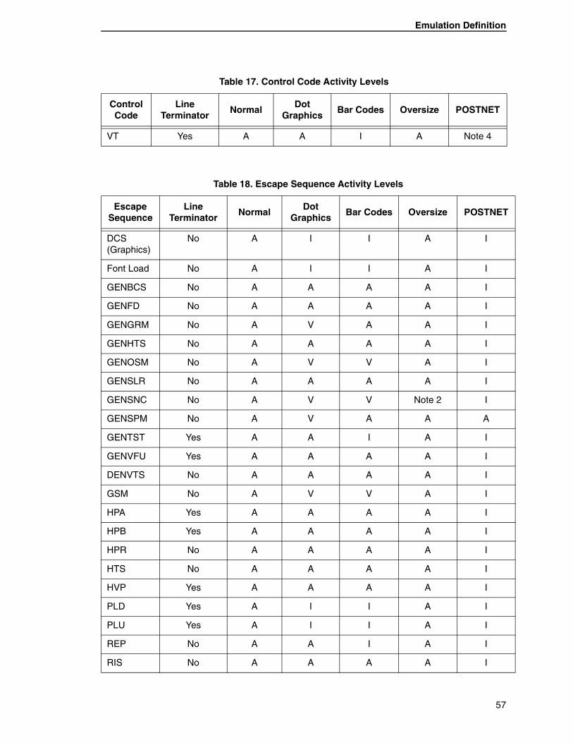
VT Yes A A I A Note 4
Table 17. Control Code Activity Levels
Control Code
Line Terminator
NormalDot
GraphicsBar Codes Oversize POSTNET
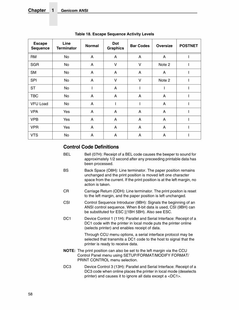
Table 18. Escape Sequence Activity Levels
Escape Sequence
Line Terminator
NormalDot
GraphicsBar Codes Oversize POSTNET
DCS (Graphics)
No A I I A I
Font Load No A I I A I
GENBCS No A A A A I
GENFD No A A A A I
GENGRM No A V A A I
GENHTS No A A A A I
GENOSM No A V V A I
GENSLR No A A A A I
GENSNC No A V V Note 2 I
GENSPM No A V A A A
GENTST Yes A A I A I
GENVFU Yes A A A A I
DENVTS No A A A A I
GSM No A V V A I
HPA Yes A A A A I
HPB Yes A A A A I
HPR No A A A A I
HTS No A A A A I
HVP Yes A A A A I
PLD Yes A I I A I
PLU Yes A I I A I
REP No A A I A I
RIS No A A A A I
57
Chapter 1 Genicom ANSI
Control Code DefinitionsBEL Bell (07H): Receipt of a BEL code causes the beeper to sound for
approximately 1/2 second after any preceeding printable data has been processed.
BS Back Space (O8H): Line terminator. The paper position remains unchanged and the print position is moved left one character space from the current. If the print position is at the left margin, no action is taken.
CR Carriage Return (ODH): Line terminator. The print positon is reset to the left margin, and the paper position is left unchanged.
CSI Control Sequence Introducer (9BH): Signals the beginning of an ANSI control sequence. When 8-bit data is used, CSI (9BH) can be substituted for ESC [(1BH 5BH). Also see ESC.
DC1 Device Control 1 (11H): Parallel and Serial Interface: Receipt of a DC1 code with the printer in local mode puts the printer online (selects printer) and enables receipt of data.
Through CCU menu options, a serial interface protocol may be selected that transmits a DC1 code to the host to signal that the printer is ready to receive data.
NOTE: The print position can also be set to the left margin via the CCU Control Panel menu using SETUP/FORMAT/MODIFY FORMAT/PRINT CONTROL menu selection.
DC3 Device Control 3 (13H): Parallel and Serial Interface: Receipt of a DC3 code when online places the printer in local mode (deselects printer) and causes it to ignore all data except a <DC1>.
RM No A A A A I
SGR No A V V Note 2 I
SM No A A A A I
SPI No A V V Note 2 I
ST No I A I I I
TBC No A A A A I
VFU Load No A I I A I
VPA Yes A A A A I
VPB Yes A A A A I
VPR Yes A A A A I
VTS No A A A A I
Table 18. Escape Sequence Activity Levels
Escape Sequence
Line Terminator
NormalDot
GraphicsBar Codes Oversize POSTNET
58
Emulation Definition
Through menu options, a serial interface protocol may be selected that transmits a <DC3> code to the host signal that the printer isnot ready to receive data.
See note for DC1 on page 58.
ESC Escape (1BH): Signals the beginning of an escape sequence. Also see CSI on page 58.
FF Form Feed (OCH): Line terminator. The paper is advanced to the next top-of-form position. When EVFU is enabled and programmed, paper will advance to the next stop in channel 1.
NOTE: An option strap from the CCU Control Panel menu using the SETUP/FORMAT/MODIFY FORMAT/GENPRTOPTS section can disable this feature.
HT Horizontal Tab (09H): Advances the print position to the next horizontal tab location. If no tabs are set, an HT code is either converted to a space or ignored, depending on the menu option settings.
LF Line Feed (OAH): Line terminator. The paper is advanced to the next line. When printing horizontal dot graphics, the paper is advanced to the next dot row.
See note for FF above.
SI Shift In (0FH): Used to exit a Special Print Mode (GENSPM) when ANSI emulation strap 1 is active.
SO Shift Out (OEH): Used to enable a special print mode (GENSPM) when ANSI emulation strap is inactive.
VT Vertical Tab (OBH): Line terminator. The paper is advanced to the next vertical tab stop. If no tabs are set, a VT code causes a line feed. When using the EVFU, paper advances to the next stop in channel 12.
See note for FF above.
59
Chapter 1 Genicom ANSI
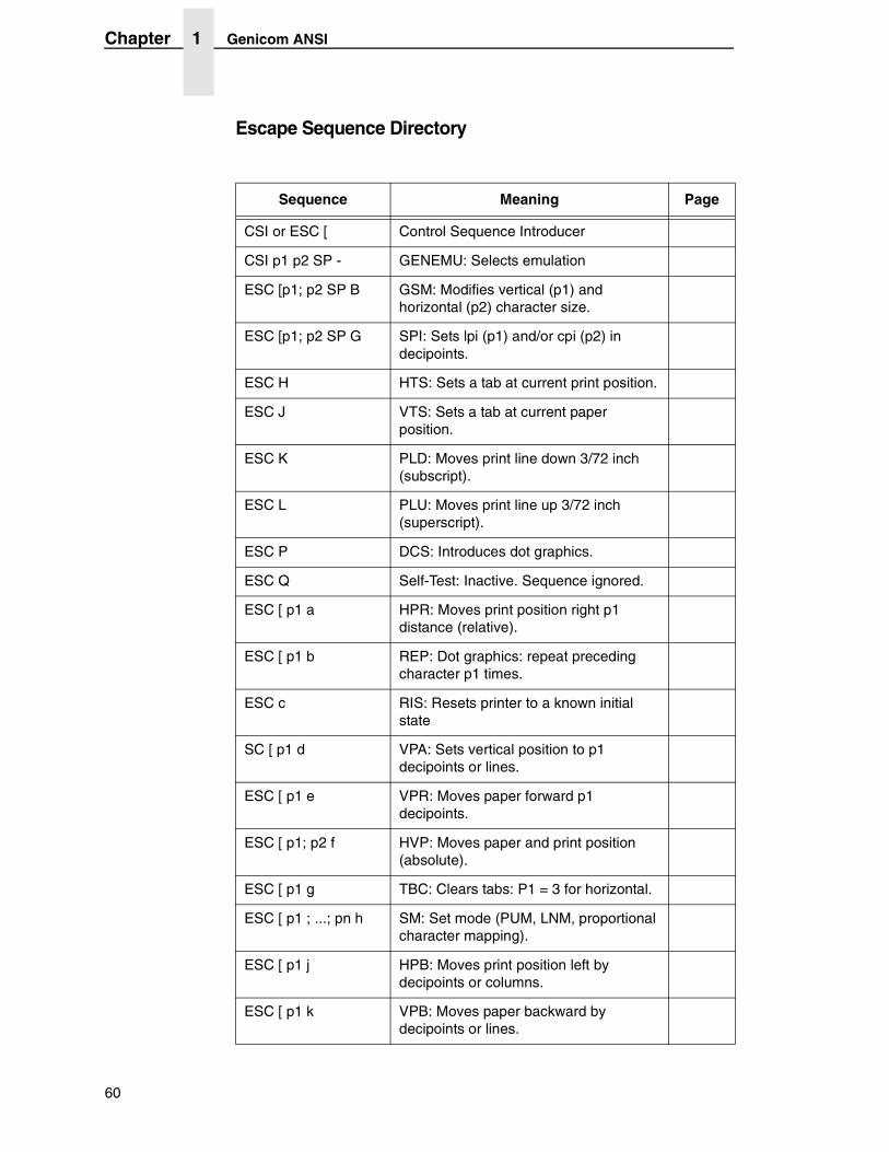
Escape Sequence Directory
Sequence Meaning Page
CSI or ESC [ Control Sequence Introducer
CSI p1 p2 SP - GENEMU: Selects emulation
ESC [p1; p2 SP B GSM: Modifies vertical (p1) and horizontal (p2) character size.
ESC [p1; p2 SP G SPI: Sets lpi (p1) and/or cpi (p2) in decipoints.
ESC H HTS: Sets a tab at current print position.
ESC J VTS: Sets a tab at current paper position.
ESC K PLD: Moves print line down 3/72 inch (subscript).
ESC L PLU: Moves print line up 3/72 inch (superscript).
ESC P DCS: Introduces dot graphics.
ESC Q Self-Test: Inactive. Sequence ignored.
ESC [ p1 a HPR: Moves print position right p1 distance (relative).
ESC [ p1 b REP: Dot graphics: repeat preceding character p1 times.
ESC c RIS: Resets printer to a known initial state
SC [ p1 d VPA: Sets vertical position to p1 decipoints or lines.
ESC [ p1 e VPR: Moves paper forward p1 decipoints.
ESC [ p1; p2 f HVP: Moves paper and print position (absolute).
ESC [ p1 g TBC: Clears tabs: P1 = 3 for horizontal.
ESC [ p1 ; ...; pn h SM: Set mode (PUM, LNM, proportional character mapping).
ESC [ p1 j HPB: Moves print position left by decipoints or columns.
ESC [ p1 k VPB: Moves paper backward by decipoints or lines.
60
Emulation Definition
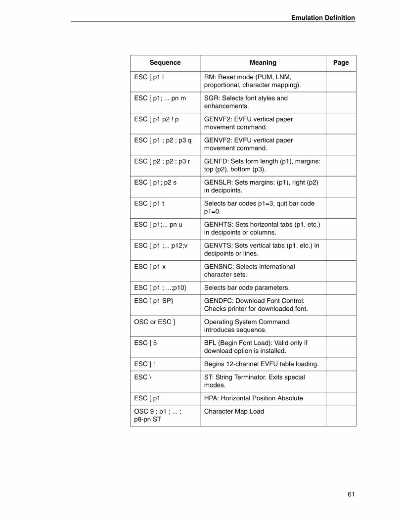
ESC [ p1 l RM: Reset mode (PUM, LNM, proportional, character mapping).
ESC [ p1; ... pn m SGR: Selects font styles and enhancements.
ESC [ p1 p2 ! p GENVF2: EVFU vertical paper movement command.
ESC [ p1 ; p2 ; p3 q GENVF2: EVFU vertical paper movement command.
ESC [ p2 ; p2 ; p3 r GENFD: Sets form length (p1), margins: top (p2), bottom (p3).
ESC [ p1; p2 s GENSLR: Sets margins: (p1), right (p2) in decipoints.
ESC [ p1 t Selects bar codes p1=3, quit bar code p1=0.
ESC [ p1;... pn u GENHTS: Sets horizontal tabs (p1, etc.) in decipoints or columns.
ESC [ p1 ;... p12;v GENVTS: Sets vertical tabs (p1, etc.) in decipoints or lines.
ESC [ p1 x GENSNC: Selects international character sets.
ESC [ p1 ; ...;p10} Selects bar code parameters.
ESC [ p1 SP} GENDFC: Download Font Control: Checks printer for downloaded font.
OSC or ESC ] Operating System Command: introduces sequence.
ESC ] 5 BFL (Begin Font Load): Valid only if download option is installed.
ESC ] ! Begins 12-channel EVFU table loading.
ESC \ ST: String Terminator. Exits special modes.
ESC [ p1 HPA: Horizontal Position Absolute
OSC 9 ; p1 ; ... ; p8-pn ST
Character Map Load
Sequence Meaning Page
61
Chapter 1 Genicom ANSI
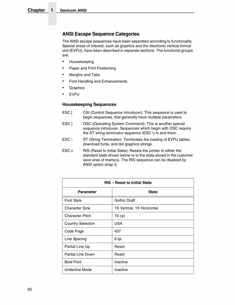
ANSI Escape Sequence CategoriesThe ANSI escape sequences have been separated according to functionality. Special areas of interest, such as graphics and the electronic vertical format unit (EVFU), have been described in separate sections. The functional groups are:
• Housekeeping
• Paper and Print Positioning
• Margins and Tabs
• Font Handling and Enhancements
• Graphics
• EVFU
Housekeeping Sequences
ESC [ CSI (Control Sequence Introducer): This sequence is used to begin sequences, that generally have multiple parameters.
ESC ] OSC (Operating System Command): This is another special sequence introducer. Sequences which begin with OSC require the ST string terminator sequence (ESC \) to end them.
ESC \ ST (String Terminator): Terminates the loading of EVFU tables, download fonts, and dot graphics strings.
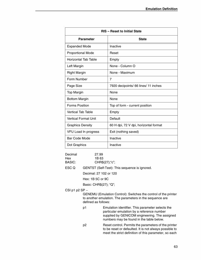
ESC c RIS (Reset to Initial State): Resets the printer to either the standard state shown below or to the state stored in the customer save area of memory. The RIS sequence can be disabled by ANSI option strap 3.
RIS – Reset to Initial State
Parameter State
Font Style Gothic Draft
Character Size 1X Vertical, 1X Horizontal
Character Pitch 10 cpi
Country Selection USA
Code Page 437
Line Spacing 6 lpi
Partial Line Up Reset
Partial Line Down Reset
Bold Print Inactive
Underline Mode Inactive
62
Emulation Definition
Decimal 27.99 Hex 1B 63 BASIC: CHR$(27);“c”;
ESC Q GENTST (Self-Test): This sequence is ignored.
Decimal: 27 102 or 120
Hex: 1B 5C or 9C
Basic: CHR$(27); “Q”;
CSI p1 p2 SP ~ GENEMU (Emulation Control): Switches the control of the printer to another emulation. The parameters in the sequence are defined as follows:
p1 Emulation identifier. This parameter selects the particular emulation by a reference number supplied by GENICOM engineering. The assigned numbers may be found in the table below.
p2 Reset control. Permits the parameters of the printer to be reset or defaulted. It is not always possible to meet the strict definition of this parameter, so each
Expanded Mode Inactive
Proportional Mode Reset
Horizontal Tab Table Empty
Left Margin None - Column O
Right Margin None - Maximum
Form Number 7
Page Size 7920 decipoints/ 66 lines/ 11 inches
Top Margin None
Bottom Margin None
Forms Position Top of form - current position
Vertical Tab Table Empty
Vertical Format Unit Default
Graphics Density 60 H dpi, 72 V dpi, horizontal format
VFU Load In progress Exit (nothing saved)
Bar Code Mode Inactive
Dot Graphics Inactive
RIS – Reset to Initial State
Parameter State
63
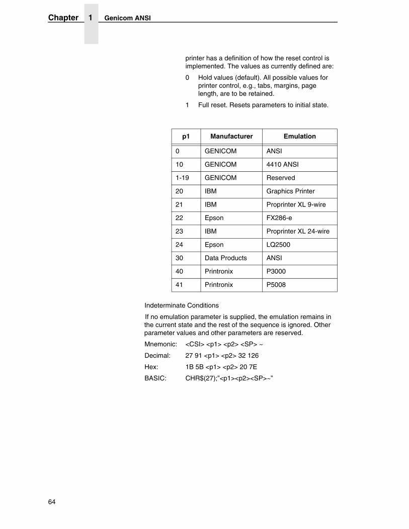
Chapter 1 Genicom ANSI
printer has a definition of how the reset control is implemented. The values as currently defined are:
0 Hold values (default). All possible values for printer control, e.g., tabs, margins, page length, are to be retained.
1 Full reset. Resets parameters to initial state.
Indeterminate Conditions
If no emulation parameter is supplied, the emulation remains in the current state and the rest of the sequence is ignored. Other parameter values and other parameters are reserved.
Mnemonic: <CSI> <p1> <p2> <SP> ~
Decimal: 27 91 <p1> <p2> 32 126
Hex: 1B 5B <p1> <p2> 20 7E
BASIC: CHR$(27);”<p1><p2><SP>~”
p1 Manufacturer Emulation
0 GENICOM ANSI
10 GENICOM 4410 ANSI
1-19 GENICOM Reserved
20 IBM Graphics Printer
21 IBM Proprinter XL 9-wire
22 Epson FX286-e
23 IBM Proprinter XL 24-wire
24 Epson LQ2500
30 Data Products ANSI
40 Printronix P3000
41 Printronix P5008
64
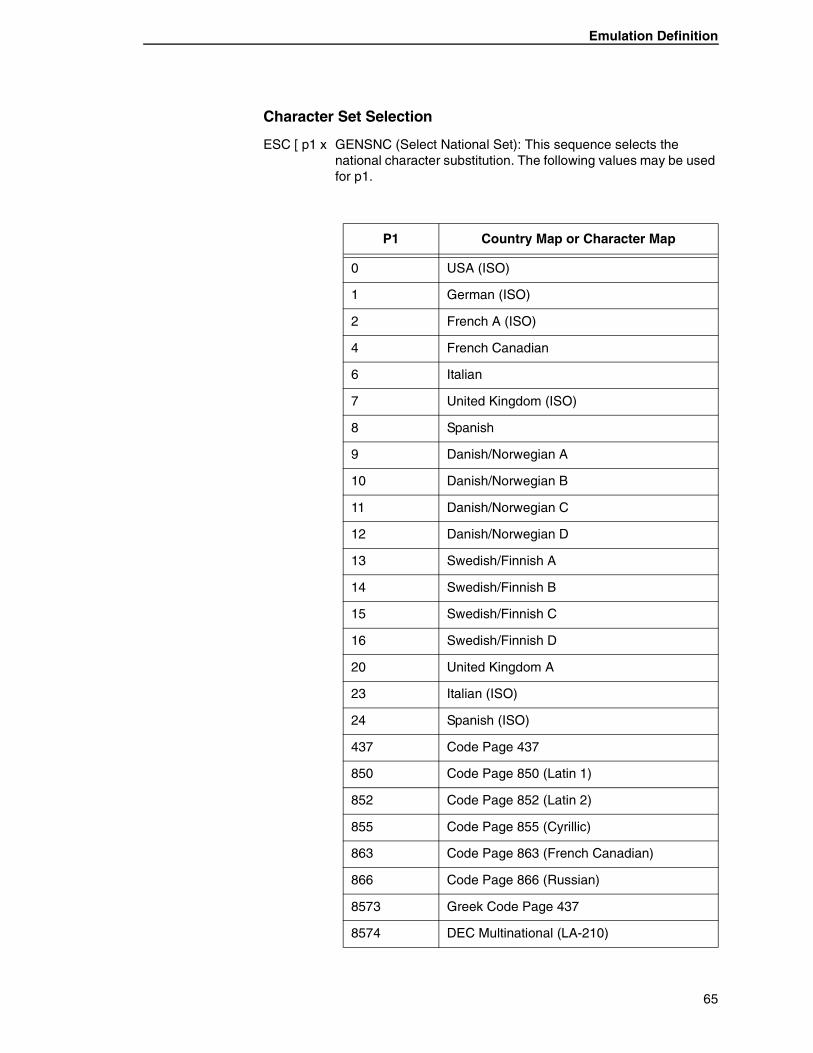
Emulation Definition
Character Set Selection
ESC [ p1 x GENSNC (Select National Set): This sequence selects the national character substitution. The following values may be used for p1.
P1 Country Map or Character Map
0 USA (ISO)
1 German (ISO)
2 French A (ISO)
4 French Canadian
6 Italian
7 United Kingdom (ISO)
8 Spanish
9 Danish/Norwegian A
10 Danish/Norwegian B
11 Danish/Norwegian C
12 Danish/Norwegian D
13 Swedish/Finnish A
14 Swedish/Finnish B
15 Swedish/Finnish C
16 Swedish/Finnish D
20 United Kingdom A
23 Italian (ISO)
24 Spanish (ISO)
437 Code Page 437
850 Code Page 850 (Latin 1)
852 Code Page 852 (Latin 2)
855 Code Page 855 (Cyrillic)
863 Code Page 863 (French Canadian)
866 Code Page 866 (Russian)
8573 Greek Code Page 437
8574 DEC Multinational (LA-210)
65
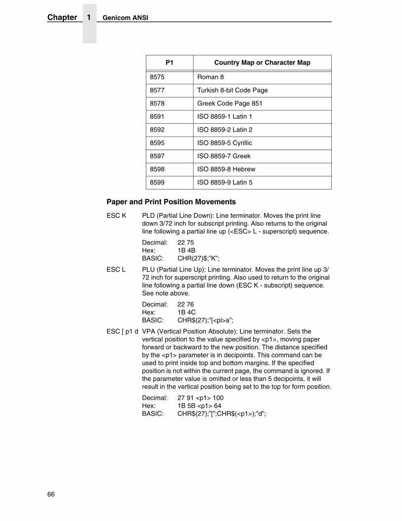
Chapter 1 Genicom ANSI
Paper and Print Position Movements
ESC K PLD (Partial Line Down): Line terminator. Moves the print line down 3/72 inch for subscript printing. Also returns to the original line following a partial line up (<ESC> L - superscript) sequence.
Decimal: 22 75 Hex: 1B 4B BASIC: CHR(27)$;”K”;
ESC L PLU (Partial Line Up): Line terminator. Moves the print line up 3/72 inch for superscript printing. Also used to return to the original line following a partial line down (ESC K - subscript) sequence. See note above.
Decimal: 22 76 Hex: 1B 4C BASIC: CHR$(27);”[<pl>a”;
ESC [ p1 d VPA (Vertical Position Absolute): Line terminator. Sets the vertical position to the value specified by <p1>, moving paper forward or backward to the new position. The distance specified by the <p1> parameter is in decipoints. This command can be used to print inside top and bottom margins. If the specified position is not within the current page, the command is ignored. If the parameter value is omitted or less than 5 decipoints, it will result in the vertical position being set to the top for form position.
Decimal: 27 91 <p1> 100 Hex: 1B 5B <p1> 64 BASIC: CHR$(27);”[”;CHR$(<p1>);”d”;
8575 Roman 8
8577 Turkish 8-bit Code Page
8578 Greek Code Page 851
8591 ISO 8859-1 Latin 1
8592 ISO 8859-2 Latin 2
8595 ISO 8859-5 Cyrillic
8597 ISO 8859-7 Greek
8598 ISO 8859-8 Hebrew
8599 ISO 8859-9 Latin 5
P1 Country Map or Character Map
66
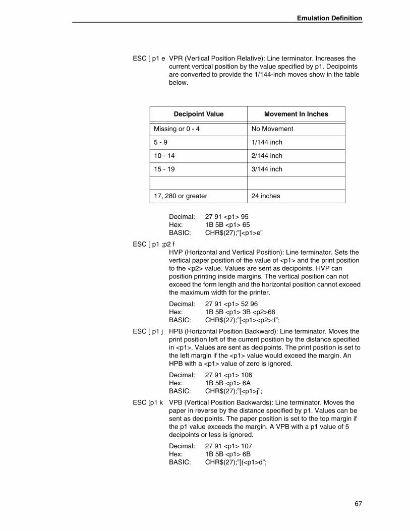
Emulation Definition
ESC [ p1 e VPR (Vertical Position Relative): Line terminator. Increases the current vertical position by the value specified by p1. Decipoints are converted to provide the 1/144-inch moves show in the table below.
Decimal: 27 91 <p1> 95 Hex: 1B 5B <p1> 65 BASIC: CHR$(27);”[<p1>e”
ESC [ p1 ;p2 f HVP (Horizontal and Vertical Position): Line terminator. Sets the vertical paper position of the value of <p1> and the print position to the <p2> value. Values are sent as decipoints. HVP can position printing inside margins. The vertical position can not exceed the form length and the horizontal position cannot exceed the maximum width for the printer.
Decimal: 27 91 <p1> 52 96 Hex: 1B 5B <p1> 3B <p2>66 BASIC: CHR$(27);”[<p1><p2>;f”;
ESC [ p1 j HPB (Horizontal Position Backward): Line terminator. Moves the print position left of the current position by the distance specified in <p1>. Values are sent as decipoints. The print position is set to the left margin if the <p1> value would exceed the margin. An HPB with a <p1> value of zero is ignored.
Decimal: 27 91 <p1> 106 Hex: 1B 5B <p1> 6A BASIC: CHR$(27);”[<p1>j”;
ESC [p1 k VPB (Vertical Position Backwards): Line terminator. Moves the paper in reverse by the distance specified by p1. Values can be sent as decipoints. The paper position is set to the top margin if the p1 value exceeds the margin. A VPB with a p1 value of 5 decipoints or less is ignored.
Decimal: 27 91 <p1> 107 Hex: 1B 5B <p1> 6B BASIC: CHR$(27);”[(<p1>d”;
Decipoint Value Movement In Inches
Missing or 0 - 4 No Movement
5 - 9 1/144 inch
10 - 14 2/144 inch
15 - 19 3/144 inch
17, 280 or greater 24 inches
67
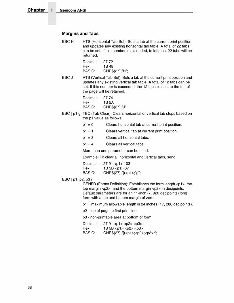
Chapter 1 Genicom ANSI
Margins and Tabs
ESC H HTS (Horizontal Tab Set): Sets a tab at the current print position and updates any existing horizontal tab table. A total of 22 tabs can be set. If this number is exceeded, te leftmost 22 tabs will be returned.
Decimal: 27 72 Hex: 1B 48 BASIC: CHR$(27);”H”;
ESC J VTS (Vertical Tab Set): Sets a tab at the current print position and updates any existing vertical tab table. A total of 12 tabs can be set. If this number is exceeded, the 12 tabs closest to the top of the page will be retained.
Decimal: 27 74 Hex: 1B 5A BASIC: CHR$(27);”J”
ESC [ p1 g TBC (Tab Clear): Clears horizontal or vertical tab stops based on the p1 value as follows:
p1 = 0 Clears horizontal tab at current print position.
p1 = 1 Clears vertical tab at current print position.
p1 = 3 Clears all horizontal tabs.
p1 = 4 Clears all vertical tabs.
More than one parameter can be used.
Example: To clear all horizontal and vertical tabs, send:
Decimal: 27 91 <p1> 103 Hex: 1B 5B <p1> 67 BASIC: CHR$(27);”[(<p1>;”g”;
ESC [ p1; p2; p3 r GENFD (Forms Definition): Establishes the form length <p1>, the top margin <p2>, and the bottom margin <p2> in decipoints. Default parameters are for an 11-inch (7, 920 decipoints) long form with a top and bottom margin of zero.
p1 = maximum allowable length is 24 inches (17, 280 decipoints).
p2 - top of page to first print line
p3 - non-printable area at bottom of form
Decimal: 27 91 <p1> <p2> <p3> r Hex: 1B 5B <p1> <p2> <p3> BASIC: CHR$(27);”[(<p1>;<p2>;<p3>r”;
68
Emulation Definition
Decimal: 27 91 <p1> <p2> <p3> 114 Hex: 1B 5B <p1> <p2> <p3> 72 BASIC: CHR$(27);”[(<p1>;<p2>;<p3>r”;
ESC [ p1; p2 s GENSLR (Set Left/Right Margins): The p parameters are distances from the left edge of the printable area of the paper. Parameter <p1> sets the left margin and <p2> sets the right margin. An omitted parameter clears that margin. Invalid parameters set the left margin to zero (column 1) and the right margin to 9, 504 decipoints (column 136 at 10 cpi for the 13.6 inch machines).
A new left margin takes effect following any ine terminator that normally calls for a print position set to the left. A new right margin takes effect when the print postion reaches the new margin.
Margin settings stored as decipoint values are enforced to the nearest 1/120 of an inch. Characterprinting operates at 1/120 of an inch.
Decimal: 27 91 <p1> <p2> 115 Hex: 1B 5B <p1> <p2> 73 BASIC: CHR$(27);”[(<p1><p2>s”;
NOTE: There is a physical left margin of .6 to 1.6 inches from the edge of the paper to the first printable column. This distance is adjustable by sliding all four tractors sideways. The margins set with this sequence begin at the first physical print position, not at the edge of the paper.
Sequence Explanation
ESC [ r Default values of 11-inch form length, zero top and bottom margins.
ESC [ 8280 r 11.5-inch form length, default top and bottom margins of zero
ESC [ ; 720 r Default length of 11 inches, top margin of 1-inch. Default bottom margin of zero.
ESC [ ; ; 720 r Default length of 11 inches, default top margin of zero, and a 1-inch bottom margin.
ESC [ 7920 ; 360 ; 360 r 11-inch form length, 1/2-inch top and bottom margins.
69
Chapter 1 Genicom ANSI
ESC [ p1 ; ... p22; u GENHTS (Multiple Horizontal Tab Set): Sets up to 22 horizontal tabs. The p parameters are set in decipoints.
If more than 22 tabs are set, the highest numbered tabs (farthest right) will be pushed out of the tab table. Tabs set in front of the left margin or beyond the right margin are not usable. Moving the margins will make them active.
Example: To place tabs at columns 10, 20, and 40 at 10 cpi, send ESC [ 10 ; 40 ; 20 u (tabs can be specified in any order).
Decimal: 27 91 <p1> 59 <p2> 59 ... <p22> 59 117 Hex: 1B 5B <p1> 3B <p2> 3B ... 3B <p22> 3B 75 BASIC: CHR$(27);”[(<p1>;<p2>; ... ;<p22>;u”
ESC [ p1 ; ...; p12 ; v GENVTS (Multiple Vertical Tab Set): Sets up to 12 vertical tabs. The p parameters are set in decipoints. If more than 12 tabs are set, the 12 tabs nearest the top of form will be retained. If a tab is set in the top margin area, it will be stored but will not be active until the margin is moved. If a tab is set beyond the bottom margin, attempting to move to that tab will advance the paper to the next top of form.
Decimal: 27 91 <p1> 59 <p2> 59 ... <p12> 59 118 Hex: 1B 5B <p1> 3B <p2> 3B ... <p12> 3B 76 BASIC: CHR$(27);”[(<p1>;<p2>; ... ;<p12>;v”;
Font Handling and Enhancements
ESC [p1; p2 SP B GSM (Graphic Size Modification): This sequence modifies the vertical <p1> and horizontal <p2> size of expanded and oversize characters. When using expanded characters, the currently selected font style is used. Oversize uses its own distinct font style.
Parameter values are percentages of the normal size character, so values over 100 are needed for expansion. Expansion factors are obtained by dividing values by 100.
Example: A parameter value of 526 would be divided by 100 to produce an expansion factor of 5 (5X expansion). Values less than 100 are treated as 1X expansion.
Mixed sizes within a line can be top or bottom justified depending on the Program Mode menu option (see VExOpt: Default and VExOpt: Baseline).
X1: 0-199 (Default) X4: 400-499 X7: 700-799
X2: 200-299 X5: 500-599 X8: 800-UP
X3: 300-399 X6: 600-699
70
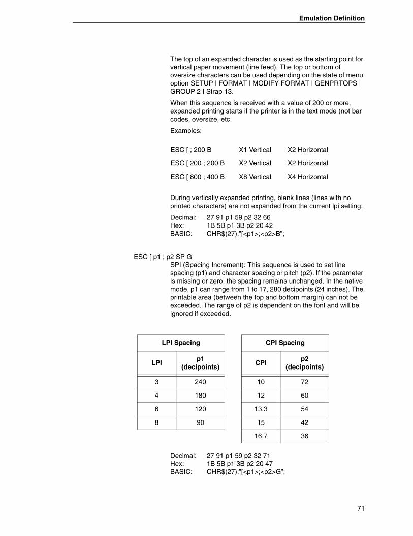
Emulation Definition
The top of an expanded character is used as the starting point for vertical paper movement (line feed). The top or bottom of oversize characters can be used depending on the state of menu option SETUP | FORMAT | MODIFY FORMAT | GENPRTOPS | GROUP 2 | Strap 13.
When this sequence is received with a value of 200 or more, expanded printing starts if the printer is in the text mode (not bar codes, oversize, etc.
Examples:
During vertically expanded printing, blank lines (lines with no printed characters) are not expanded from the current lpi setting.
Decimal: 27 91 p1 59 p2 32 66 Hex: 1B 5B p1 3B p2 20 42 BASIC: CHR$(27);”[<p1>;<p2>B”;
ESC [ p1 ; p2 SP G SPI (Spacing Increment): This sequence is used to set line spacing (p1) and character spacing or pitch (p2). If the parameter is missing or zero, the spacing remains unchanged. In the native mode, p1 can range from 1 to 17, 280 decipoints (24 inches). The printable area (between the top and bottom margin) can not be exceeded. The range of p2 is dependent on the font and will be ignored if exceeded.
Decimal: 27 91 p1 59 p2 32 71 Hex: 1B 5B p1 3B p2 20 47 BASIC: CHR$(27);”[<p1>;<p2>G”;
ESC [ ; 200 B X1 Vertical X2 Horizontal
ESC [ 200 ; 200 B X2 Vertical X2 Horizontal
ESC [ 800 ; 400 B X8 Vertical X4 Horizontal
LPI Spacing
LPIp1
(decipoints)
3 240
4 180
6 120
8 90
CPI Spacing
CPIp2
(decipoints)
10 72
12 60
13.3 54
15 42
16.7 36
71
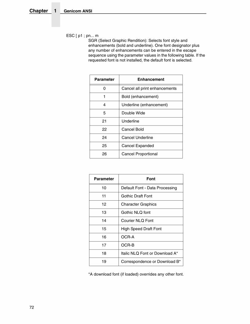
Chapter 1 Genicom ANSI
ESC [ p1 ; pn... m SGR (Select Graphic Rendition): Selects font style and enhancements (bold and underline). One font designator plus any number of enhancements can be entered in the escape sequence using the parameter values in the following table. If the requested font is not installed, the default font is selected.
*A download font (if loaded) overrides any other font.
Parameter Enhancement
0 Cancel all print enhancements
1 Bold (enhancement)
4 Underline (enhancement)
5 Double Wide
21 Underline
22 Cancel Bold
24 Cancel Underline
25 Cancel Expanded
26 Cancel Proportional
Parameter Font
10 Default Font - Data Processing
11 Gothic Draft Font
12 Character Graphics
13 Gothic NLQ font
14 Courier NLQ Font
15 High Speed Draft Font
16 OCR-A
17 OCR-B
18 Italic NLQ Font or Download A*
19 Correspondence or Download B*
72
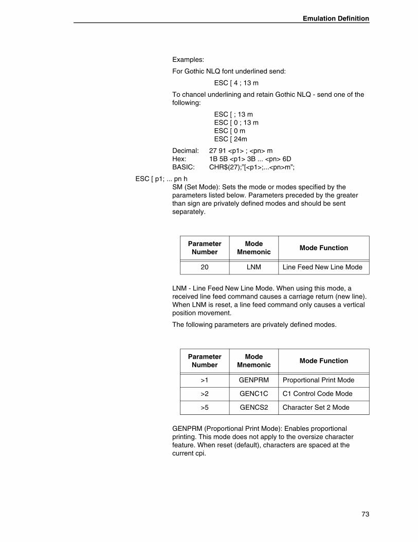
Emulation Definition
Examples:
For Gothic NLQ font underlined send:
ESC [ 4 ; 13 m
To chancel underlining and retain Gothic NLQ - send one of the following:
ESC [ ; 13 m ESC [ 0 ; 13 m ESC [ 0 m ESC [ 24m
Decimal: 27 91 <p1> ; <pn> m Hex: 1B 5B <p1> 3B ... <pn> 6D BASIC: CHR$(27);”[<p1>;...<pn>m”;
ESC [ p1; ... pn h SM (Set Mode): Sets the mode or modes specified by the parameters listed below. Parameters preceded by the greater than sign are privately defined modes and should be sent separately.
LNM - Line Feed New Line Mode. When using this mode, a received line feed command causes a carriage return (new line). When LNM is reset, a line feed command only causes a vertical position movement.
The following parameters are privately defined modes.
GENPRM (Proportional Print Mode): Enables proportional printing. This mode does not apply to the oversize character feature. When reset (default), characters are spaced at the current cpi.
Parameter Number
Mode Mnemonic
Mode Function
20 LNM Line Feed New Line Mode
Parameter Number
Mode Mnemonic
Mode Function
>1 GENPRM Proportional Print Mode
>2 GENC1C C1 Control Code Mode
>5 GENCS2 Character Set 2 Mode
73
Chapter 1 Genicom ANSI
GENC1C (C1 Control Code Mode - PC Set 1): When set, it allows the use of C1 control codes. When reset, 80H - 9FH are ignored. The default state is set using ANSI emultion option 6.
GENSC2 (Character Set 2 Mode - PC Set 2): Selects character set 2 of any of the 8-bit international character sets. The default state is set using option strap 7 in the ANSI emulation options.
Example: To print proportional, send ESC [ > 1h.
Decimal: 27 91 62 49 104 Hex: 1B 5B 3E 31 68 BASIC: CHR$(27);”[>1h”;
ESC [ p1 ... pn1 RM (Reset Mode): Resets any modes turned on by the Set Mode command above. Parameters and syntax are the same.
ESC ] 5 BFL (Begin Font Load): This sequence is not honored when self-test determines that the download font option is not installed. Permits downloading of customer-defined font characters into printer nonvolatile memory from the host. Loading is terminated when an ESC \ sequence is received.
Decimal: 27 93 53 Hex: 1B 5D 35 BASIC: CHR$(27);”]5”;
ESC [ p1 SP ] GENDFC (Download Font Control): Using the serial interface, this command allows the host to see if at least one valid font is loaded (p1=p2). The printer sends DCS 30H 30H ST if a font is loaded, DCS 44H 45H ST if no font is loaded. It also provides the capability to erase the download font area (p1=1).
Decimal: 27 91 <p1> 32 125 Hex: 1B 5D <p1> 20 7D BASIC: CHR$(27);”[<p1>}”;
74
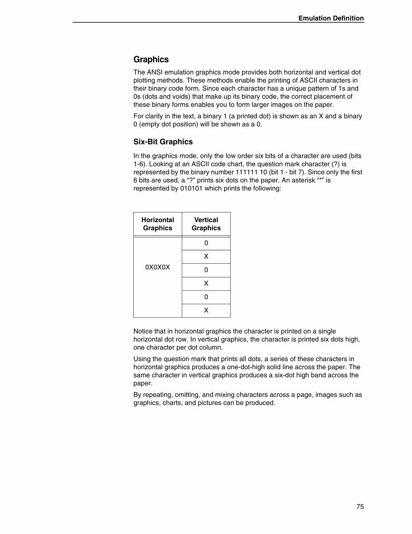
Emulation Definition
GraphicsThe ANSI emulation graphics mode provides both horizontal and vertical dot plotting methods. These methods enable the printing of ASCII characters in their binary code form. Since each character has a unique pattern of 1s and 0s (dots and voids) that make up its binary code, the correct placement of these binary forms enables you to form larger images on the paper.
For clarity in the text, a binary 1 (a printed dot) is shown as an X and a binary 0 (empty dot position) will be shown as a 0.
Six-Bit Graphics
In the graphics mode, only the low order six bits of a character are used (bits 1-6). Looking at an ASCII code chart, the question mark character (?) is represented by the binary number 111111 10 (bit 1 - bit 7). Since only the first 6 bits are used, a “?” prints six dots on the paper. An asterisk “*” is represented by 010101 which prints the following:
Notice that in horizontal graphics the character is printed on a single horizontal dot row. In vertical graphics, the character is printed six dots high, one character per dot column.
Using the question mark that prints all dots, a series of these characters in horizontal graphics produces a one-dot-high solid line across the paper. The same character in vertical graphics produces a six-dot high band across the paper.
By repeating, omitting, and mixing characters across a page, images such as graphics, charts, and pictures can be produced.
Horizontal Graphics
Vertical Graphics
0X0X0X
0
X
0
X
0
X
75
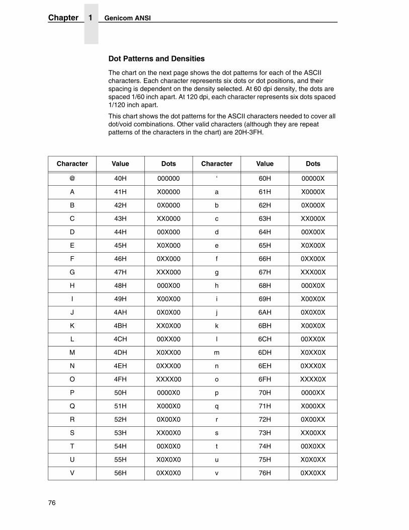
Chapter 1 Genicom ANSI
Dot Patterns and Densities
The chart on the next page shows the dot patterns for each of the ASCII characters. Each character represents six dots or dot positions, and their spacing is dependent on the density selected. At 60 dpi density, the dots are spaced 1/60 inch apart. At 120 dpi, each character represents six dots spaced 1/120 inch apart.
This chart shows the dot patterns for the ASCII characters needed to cover all dot/void combinations. Other valid characters (although they are repeat patterns of the characters in the chart) are 20H-3FH.
Character Value Dots Character Value Dots
@ 40H 000000 ‘ 60H 00000X
A 41H X00000 a 61H X0000X
B 42H 0X0000 b 62H 0X000X
C 43H XX0000 c 63H XX000X
D 44H 00X000 d 64H 00X00X
E 45H X0X000 e 65H X0X00X
F 46H 0XX000 f 66H 0XX00X
G 47H XXX000 g 67H XXX00X
H 48H 000X00 h 68H 000X0X
I 49H X00X00 i 69H X00X0X
J 4AH 0X0X00 j 6AH 0X0X0X
K 4BH XX0X00 k 6BH X00X0X
L 4CH 00XX00 l 6CH 00XX0X
M 4DH X0XX00 m 6DH X0XX0X
N 4EH 0XXX00 n 6EH 0XXX0X
O 4FH XXXX00 o 6FH XXXX0X
P 50H 0000X0 p 70H 0000XX
Q 51H X000X0 q 71H X000XX
R 52H 0X00X0 r 72H 0X00XX
S 53H XX00X0 s 73H XX00XX
T 54H 00X0X0 t 74H 00X0XX
U 55H X0X0X0 u 75H X0X0XX
V 56H 0XX0X0 v 76H 0XX0XX
76
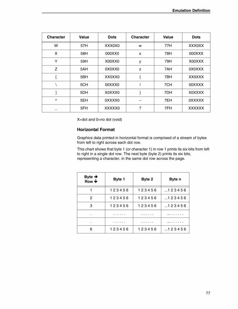
Emulation Definition
X=dot and 0=no dot (void)
Horizontal Format
Graphics data printed in horizontal format is comprised of a stream of bytes from left to right across each dot row.
This chart shows that byte 1 (or character 1) in row 1 prints its six bits from left to right in a single dot row. The next byte (byte 2) prints its six bits, representing a character, in the same dot row across the page.
W 57H XXX0X0 w 77H XXX0XX
X 58H 000XX0 x 78H 000XXX
Y 59H X00XX0 y 79H X00XXX
Z 5AH 0X0XX0 z 7AH 0X0XXX
[ 5BH XX0XX0 { 7BH XX0XXX
\ 5CH 00XXX0 | 7CH 00XXXX
] 5DH X0XXX0 } 7DH X0XXXX
^ 5EH 0XXXX0 ~ 7EH 0XXXXX
_ 5FH XXXXX0 ? 7FH XXXXXX
Character Value Dots Character Value Dots
Byte �Row �
Byte 1 Byte 2 Byte n
1 1 2 3 4 5 6 1 2 3 4 5 6 ...1 2 3 4 5 6
2 1 2 3 4 5 6 1 2 3 4 5 6 ...1 2 3 4 5 6
3 1 2 3 4 5 6 1 2 3 4 5 6 ...1 2 3 4 5 6
. . . . . . . . . . . . . ... . . . . . .
. . . . . . . . . . . . . ... . . . . . .
6 1 2 3 4 5 6 1 2 3 4 5 6 ...1 2 3 4 5 6
77

Chapter 1 Genicom ANSI
Vertical Format
In vertical format, each byte (or character) occupies six dot rows of one column. Each character is one dot wide and six dots high. The next character (byte 2) is printed beside the first, moving from left to right across the page.
Eight-Bit Graphics
• Horizontal Format
Graphics data printed in horizontal format is comprised of a stream of bytes from left to right across each dot row.
This chart shows that a byte 1 (or character 1) in row 1 prints its eight bits from left to right in a single dot row. The next byte (byte 2) prints its eight bits, representing a character, in the same dot row across the page.
Byte � 1 2 3 ...n
Row bit bit bit ...bit
1 1 1 1 ...1
2 2 2 2 ...2
3 3 3 3 ...3
4 4 4 4 ...4
5 5 5 5 ...5
6 6 6 6 ...6
Byte �Row �
Byte 1 Byte 2 Byte n
1 1 2 3 4 5 6 7 8 1 2 3 4 5 6 7 8 ...1 2 3 4 5 6 7 8
2 1 2 3 4 5 6 7 8 1 2 3 4 5 6 7 8 ...1 2 3 4 5 6 7 8
3 1 2 3 4 5 6 7 8 1 2 3 4 5 6 7 8 ...1 2 3 4 5 6 7 8
. . . . . . . . . . . . . ... . . . . . .
. . . . . . . . . . . . . ... . . . . . .
8 1 2 3 4 5 6 7 8 1 2 3 4 5 6 7 8 ...1 2 3 4 5 6 7 8
78
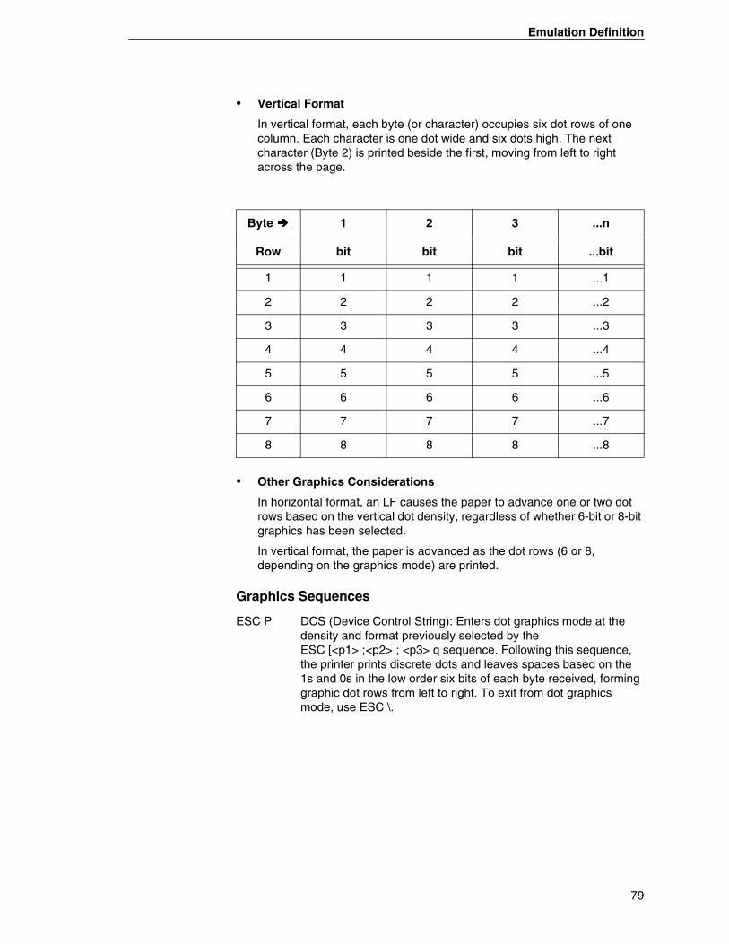
Emulation Definition
• Vertical Format
In vertical format, each byte (or character) occupies six dot rows of one column. Each character is one dot wide and six dots high. The next character (Byte 2) is printed beside the first, moving from left to right across the page.
• Other Graphics Considerations
In horizontal format, an LF causes the paper to advance one or two dot rows based on the vertical dot density, regardless of whether 6-bit or 8-bit graphics has been selected.
In vertical format, the paper is advanced as the dot rows (6 or 8, depending on the graphics mode) are printed.
Graphics Sequences
ESC P DCS (Device Control String): Enters dot graphics mode at the density and format previously selected by the ESC [<p1> ;<p2> ; <p3> q sequence. Following this sequence, the printer prints discrete dots and leaves spaces based on the 1s and 0s in the low order six bits of each byte received, forming graphic dot rows from left to right. To exit from dot graphics mode, use ESC \.
Byte � 1 2 3 ...n
Row bit bit bit ...bit
1 1 1 1 ...1
2 2 2 2 ...2
3 3 3 3 ...3
4 4 4 4 ...4
5 5 5 5 ...5
6 6 6 6 ...6
7 7 7 7 ...7
8 8 8 8 ...8
79
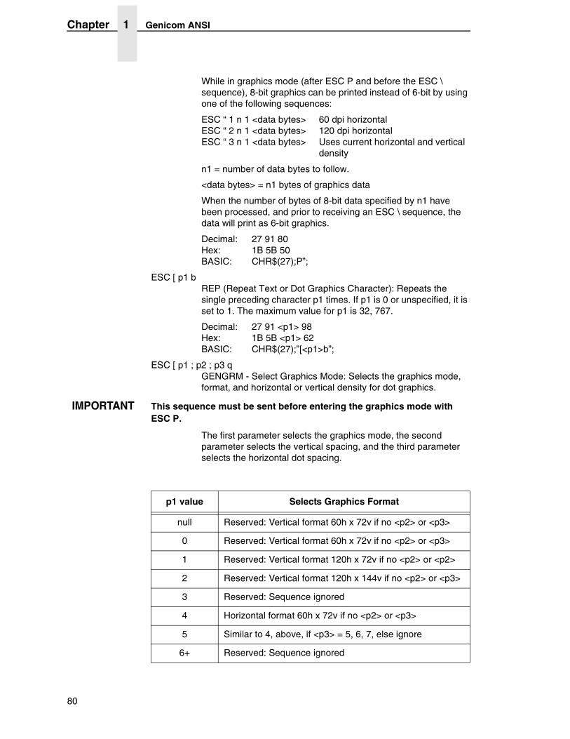
Chapter 1 Genicom ANSI
While in graphics mode (after ESC P and before the ESC \ sequence), 8-bit graphics can be printed instead of 6-bit by using one of the following sequences:
ESC “ 1 n 1 <data bytes> 60 dpi horizontal ESC “ 2 n 1 <data bytes> 120 dpi horizontal ESC “ 3 n 1 <data bytes> Uses current horizontal and vertical
density
n1 = number of data bytes to follow.
<data bytes> = n1 bytes of graphics data
When the number of bytes of 8-bit data specified by n1 have been processed, and prior to receiving an ESC \ sequence, the data will print as 6-bit graphics.
Decimal: 27 91 80 Hex: 1B 5B 50 BASIC: CHR$(27);P”;
ESC [ p1 b REP (Repeat Text or Dot Graphics Character): Repeats the single preceding character p1 times. If p1 is 0 or unspecified, it is set to 1. The maximum value for p1 is 32, 767.
Decimal: 27 91 <p1> 98 Hex: 1B 5B <p1> 62 BASIC: CHR$(27);”[<p1>b”;
ESC [ p1 ; p2 ; p3 q GENGRM - Select Graphics Mode: Selects the graphics mode, format, and horizontal or vertical density for dot graphics.
IMPORTANT This sequence must be sent before entering the graphics mode with ESC P.
The first parameter selects the graphics mode, the second parameter selects the vertical spacing, and the third parameter selects the horizontal dot spacing.
p1 value Selects Graphics Format
null Reserved: Vertical format 60h x 72v if no <p2> or <p3>
0 Reserved: Vertical format 60h x 72v if no <p2> or <p3>
1 Reserved: Vertical format 120h x 72v if no <p2> or <p2>
2 Reserved: Vertical format 120h x 144v if no <p2> or <p3>
3 Reserved: Sequence ignored
4 Horizontal format 60h x 72v if no <p2> or <p3>
5 Similar to 4, above, if <p3> = 5, 6, 7, else ignore
6+ Reserved: Sequence ignored
80
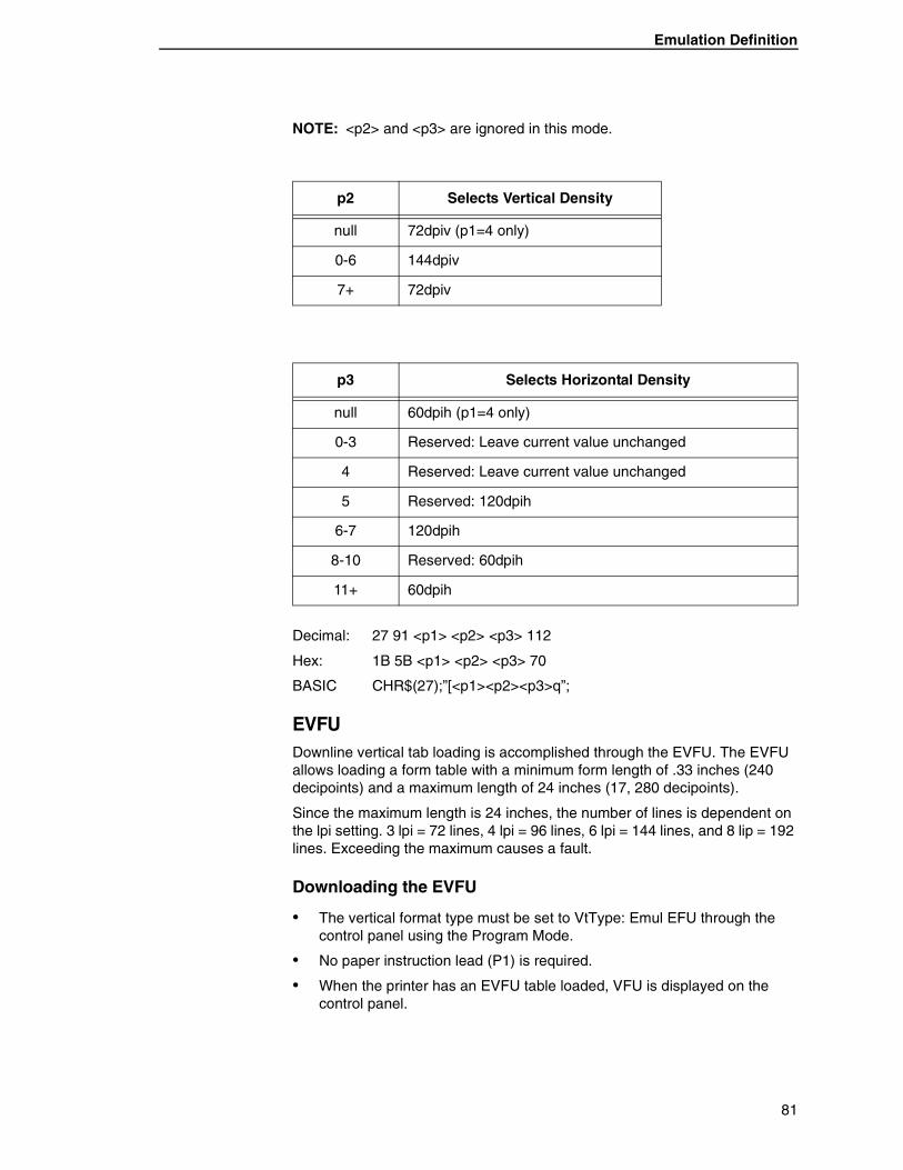
Emulation Definition
NOTE: <p2> and <p3> are ignored in this mode.
Decimal: 27 91 <p1> <p2> <p3> 112
Hex: 1B 5B <p1> <p2> <p3> 70
BASIC CHR$(27);”[<p1><p2><p3>q”;
EVFUDownline vertical tab loading is accomplished through the EVFU. The EVFU allows loading a form table with a minimum form length of .33 inches (240 decipoints) and a maximum length of 24 inches (17, 280 decipoints).
Since the maximum length is 24 inches, the number of lines is dependent on the lpi setting. 3 lpi = 72 lines, 4 lpi = 96 lines, 6 lpi = 144 lines, and 8 lip = 192 lines. Exceeding the maximum causes a fault.
Downloading the EVFU
• The vertical format type must be set to VtType: Emul EFU through the control panel using the Program Mode.
• No paper instruction lead (P1) is required.
• When the printer has an EVFU table loaded, VFU is displayed on the control panel.
p2 Selects Vertical Density
null 72dpiv (p1=4 only)
0-6 144dpiv
7+ 72dpiv
p3 Selects Horizontal Density
null 60dpih (p1=4 only)
0-3 Reserved: Leave current value unchanged
4 Reserved: Leave current value unchanged
5 Reserved: 120dpih
6-7 120dpih
8-10 Reserved: 60dpih
11+ 60dpih
81
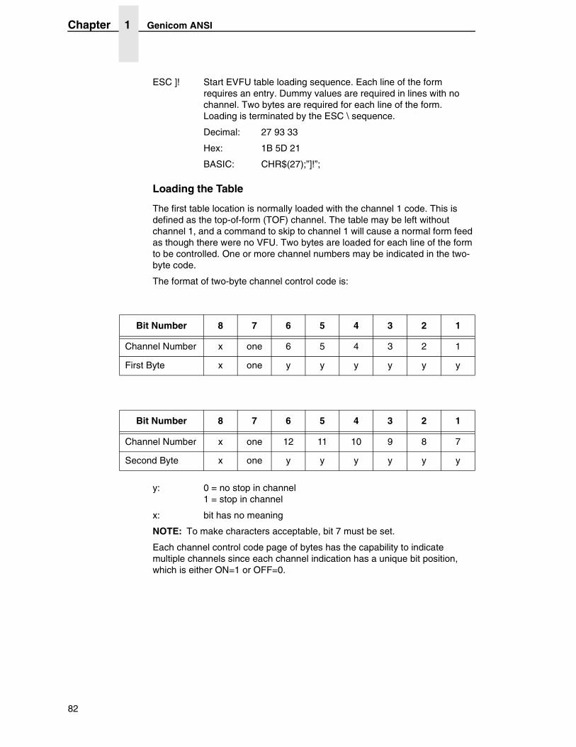
Chapter 1 Genicom ANSI
ESC ]! Start EVFU table loading sequence. Each line of the form requires an entry. Dummy values are required in lines with no channel. Two bytes are required for each line of the form. Loading is terminated by the ESC \ sequence.
Decimal: 27 93 33
Hex: 1B 5D 21
BASIC: CHR$(27);”]!”;
Loading the Table
The first table location is normally loaded with the channel 1 code. This is defined as the top-of-form (TOF) channel. The table may be left without channel 1, and a command to skip to channel 1 will cause a normal form feed as though there were no VFU. Two bytes are loaded for each line of the form to be controlled. One or more channel numbers may be indicated in the two-byte code.
The format of two-byte channel control code is:
y: 0 = no stop in channel 1 = stop in channel
x: bit has no meaning
NOTE: To make characters acceptable, bit 7 must be set.
Each channel control code page of bytes has the capability to indicate multiple channels since each channel indication has a unique bit position, which is either ON=1 or OFF=0.
Bit Number 8 7 6 5 4 3 2 1
Channel Number x one 6 5 4 3 2 1
First Byte x one y y y y y y
Bit Number 8 7 6 5 4 3 2 1
Channel Number x one 12 11 10 9 8 7
Second Byte x one y y y y y y
82
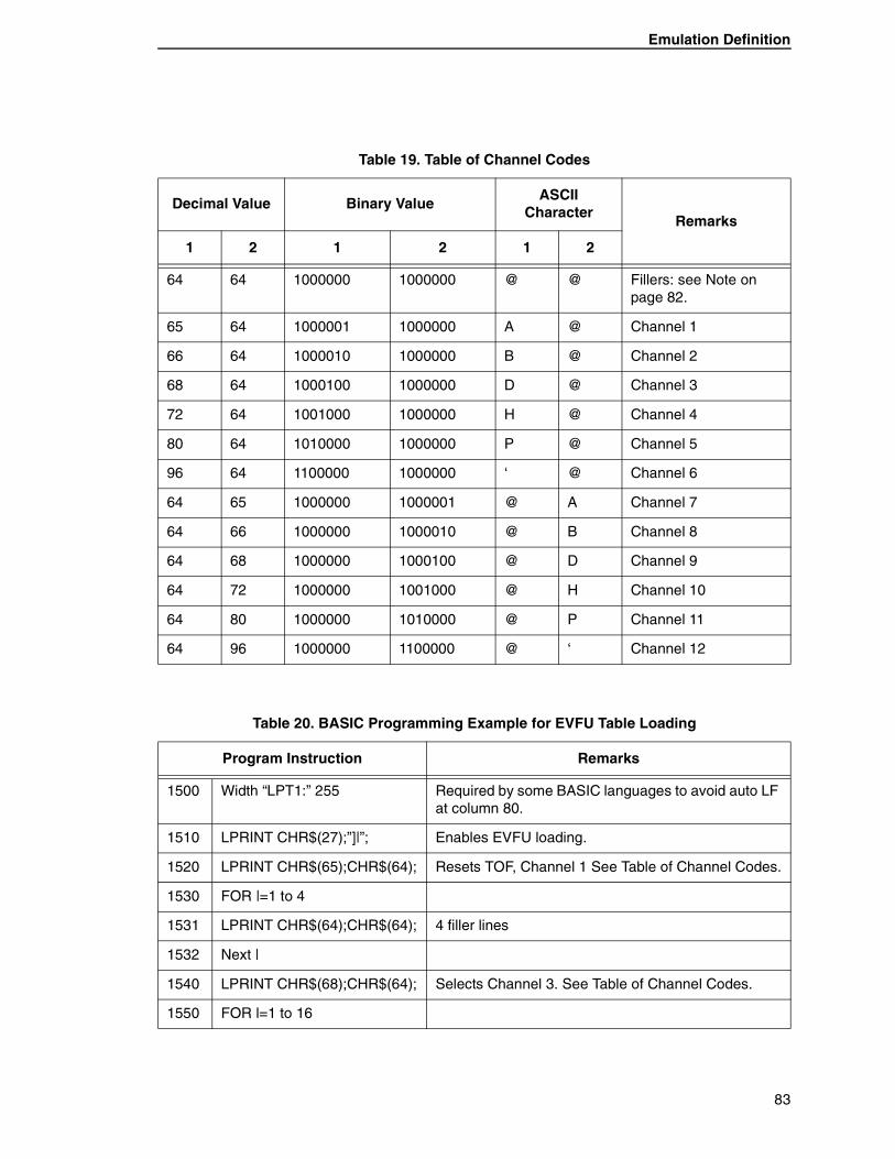
Emulation Definition
Table 19. Table of Channel Codes
Decimal Value Binary ValueASCII
CharacterRemarks
1 2 1 2 1 2
64 64 1000000 1000000 @ @ Fillers: see Note on page 82.
65 64 1000001 1000000 A @ Channel 1
66 64 1000010 1000000 B @ Channel 2
68 64 1000100 1000000 D @ Channel 3
72 64 1001000 1000000 H @ Channel 4
80 64 1010000 1000000 P @ Channel 5
96 64 1100000 1000000 ‘ @ Channel 6
64 65 1000000 1000001 @ A Channel 7
64 66 1000000 1000010 @ B Channel 8
64 68 1000000 1000100 @ D Channel 9
64 72 1000000 1001000 @ H Channel 10
64 80 1000000 1010000 @ P Channel 11
64 96 1000000 1100000 @ ‘ Channel 12
Table 20. BASIC Programming Example for EVFU Table Loading
Program Instruction Remarks
1500 Width “LPT1:” 255 Required by some BASIC languages to avoid auto LF at column 80.
1510 LPRINT CHR$(27);”]|”; Enables EVFU loading.
1520 LPRINT CHR$(65);CHR$(64); Resets TOF, Channel 1 See Table of Channel Codes.
1530 FOR |=1 to 4
1531 LPRINT CHR$(64);CHR$(64); 4 filler lines
1532 Next |
1540 LPRINT CHR$(68);CHR$(64); Selects Channel 3. See Table of Channel Codes.
1550 FOR l=1 to 16
83
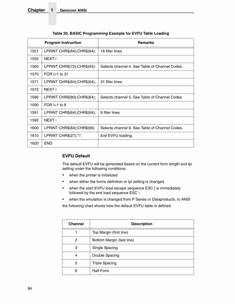
Chapter 1 Genicom ANSI
EVFU Default
The default EVFU will be generated based on the current form length and lpi setting under the following conditions:
• when the printer is initialized
• when either the forms definition or lpi setting is changed
• when the start EVFU load escape sequence ESC ] is immediately followed by the end load sequence ESC \
• when the emulation is changed from P Series or Dataproducts, to ANSI
the following chart shows how the default EVFU table is defined.
1551 LPRINT CHR$(64);CHR$(64); 16 filler lines
1552 NEXT |
1560 LPRINT CHR$(72);CHR$(64); Selects channel 4. See Table of Channel Codes.
1570 FOR |=1 to 31
1571 LPRINT CHR$(64);CHR$(64); 31 filler lines.
1572 NEXT |
1580 LPRINT CHR$(80);CHR$(64); Selects channel 5. See Table of Channel Codes.
1590 FOR |=1 to 8
1591 LPRINT CHR$(64);CHR$(64); 8 filler lines
1592 NEXT |
1600 LPRINT CHR$(64);CHR$(66) Selects channel 8. See Table of Channel Codes.
1610 LPRINT CHR$(27);”\”; Exit EVFU loading.
1620 END
Table 20. BASIC Programming Example for EVFU Table Loading
Program Instruction Remarks
Channel Description
1 Top Margin (first line)
2 Bottom Margin (last line)
3 Single Spacing
4 Double Spacing
5 Triple Spacing
6 Half Form
84
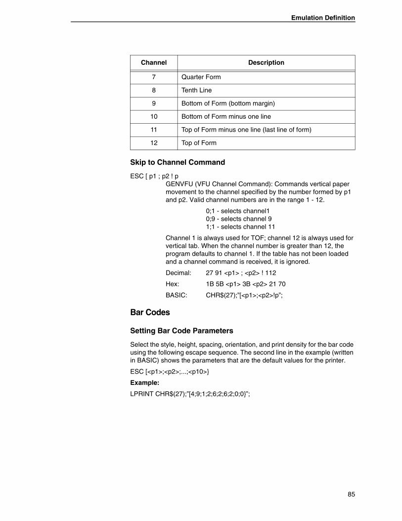
Emulation Definition
Skip to Channel Command
ESC [ p1 ; p2 ! p GENVFU (VFU Channel Command): Commands vertical paper movement to the channel specified by the number formed by p1 and p2. Valid channel numbers are in the range 1 - 12.
0;1 - selects channel1 0;9 - selects channel 9 1;1 - selects channel 11
Channel 1 is always used for TOF; channel 12 is always used for vertical tab. When the channel number is greater than 12, the program defaults to channel 1. If the table has not been loaded and a channel command is received, it is ignored.
Decimal: 27 91 <p1> ; <p2> ! 112
Hex: 1B 5B <p1> 3B <p2> 21 70
BASIC: CHR$(27);”[<p1>;<p2>!p”;
Bar Codes
Setting Bar Code Parameters
Select the style, height, spacing, orientation, and print density for the bar code using the following escape sequence. The second line in the example (written in BASIC) shows the parameters that are the default values for the printer.
ESC [<p1>;<p2>;...;<p10>}
Example:
LPRINT CHR$(27);”[4;9;1;2;6;2;6;2;0;0}”;
7 Quarter Form
8 Tenth Line
9 Bottom of Form (bottom margin)
10 Bottom of Form minus one line
11 Top of Form minus one line (last line of form)
12 Top of Form
Channel Description
85
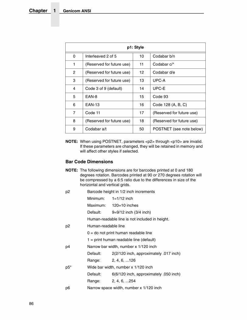
Chapter 1 Genicom ANSI
NOTE: When using POSTNET, parameters <p2> through <p10> are invalid. If these parameters are changed, they will be retained in memory and will affect other styles if selected.
Bar Code Dimensions
NOTE: The following dimensions are for barcodes printed at 0 and 180 degrees rotation. Barcodes printed at 90 or 270 degrees rotation will be compressed by a 6:5 ratio due to the differences in size of the horizontal and vertical grids.
p2 Barcode height in 1/2 inch increments
Minimum: 1=1/12 inch
Maximum: 120=10 inches
Default: 9=9/12 inch (3/4 inch)
Human-readable line is not included in height.
p2 Human-readable line
0 = do not print human readable line
1 = print human readable line (default)
p4 Narrow bar width, number x 1/120 inch
Default: 2(2/120 inch, approximately .017 inch)
Range: 2, 4, 6, ...126
p5* Wide bar width, number x 1/120 inch
Default: 6(6/120 inch, approximately .050 inch)
Range: 2, 4, 6, ...254
p6 Narrow space width, number x 1/120 inch
p1: Style
0 Interleaved 2 of 5 10 Codabar b/n
1 (Reserved for future use) 11 Codabar c/*
2 (Reserved for future use) 12 Codabar d/e
3 (Reserved for future use) 13 UPC-A
4 Code 3 of 9 (default) 14 UPC-E
5 EAN-8 15 Code 93
6 EAN-13 16 Code 128 (A, B, C)
7 Code 11 17 (Reserved for future use)
8 (Reserved for future use) 18 (Reserved for future use)
9 Codabar a/t 50 POSTNET (see note below)
86
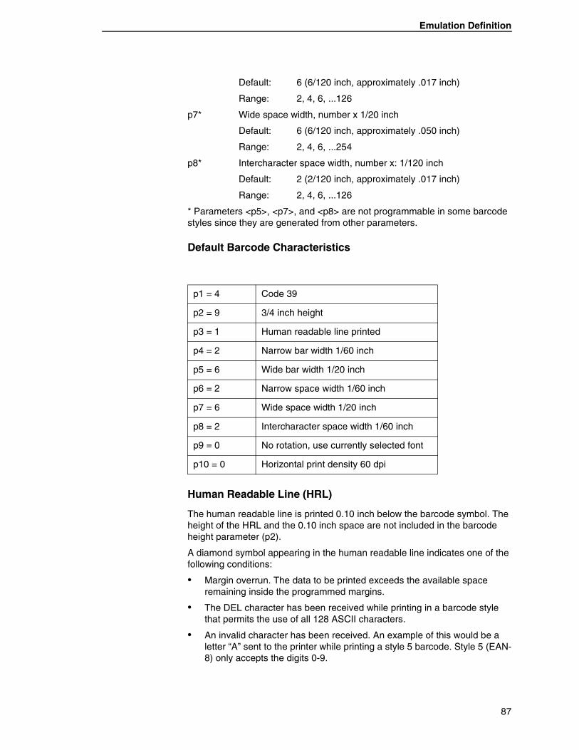
Emulation Definition
Default: 6 (6/120 inch, approximately .017 inch)
Range: 2, 4, 6, ...126
p7* Wide space width, number x 1/20 inch
Default: 6 (6/120 inch, approximately .050 inch)
Range: 2, 4, 6, ...254
p8* Intercharacter space width, number x: 1/120 inch
Default: 2 (2/120 inch, approximately .017 inch)
Range: 2, 4, 6, ...126
* Parameters <p5>, <p7>, and <p8> are not programmable in some barcode styles since they are generated from other parameters.
Default Barcode Characteristics
Human Readable Line (HRL)
The human readable line is printed 0.10 inch below the barcode symbol. The height of the HRL and the 0.10 inch space are not included in the barcode height parameter (p2).
A diamond symbol appearing in the human readable line indicates one of the following conditions:
• Margin overrun. The data to be printed exceeds the available space remaining inside the programmed margins.
• The DEL character has been received while printing in a barcode style that permits the use of all 128 ASCII characters.
• An invalid character has been received. An example of this would be a letter “A” sent to the printer while printing a style 5 barcode. Style 5 (EAN-8) only accepts the digits 0-9.
p1 = 4 Code 39
p2 = 9 3/4 inch height
p3 = 1 Human readable line printed
p4 = 2 Narrow bar width 1/60 inch
p5 = 6 Wide bar width 1/20 inch
p6 = 2 Narrow space width 1/60 inch
p7 = 6 Wide space width 1/20 inch
p8 = 2 Intercharacter space width 1/60 inch
p9 = 0 No rotation, use currently selected font
p10 = 0 Horizontal print density 60 dpi
87
Chapter 1 Genicom ANSI
Font Styles and Enhancements
Non-rotated barcodes can be printed with an HRL in any of the fonts available to the printer.
If enhancements are desired (e.g., bold, underline, or expanded) the HRL must be printed using the normal text mode. Print the barcode symbol(s) without the HRL first. Exit the barcode mode and print the HRL using the normal text mode with enhancements.
Rotated barcodes use a special font for the human readable line.
Spacing and Barcode Editing Aids
There is a 0.25 inch space called a quiet zone at the beginning and end of every barcode. As a result, the minimum distance between two horizontal barcodes is 0.50 inch.
Most barcode styles accept commas, spaces, and horizontal tabs are delimiters to separate barcodes. A comma adds no additional space between barcodes, so the separate is the width of the quiet zone for a total 0.60 inch separation. A horizontal tab adds the appropriate number of empty spaces to go to the next tab.
Oversize Character FontThe oversize font is composed of special block-style characters that can be expanded 156 times the size of standard fonts. This will produce letters up to 15.25 inches (388mm) high by 13 inches (330mm) wide. Oversize characters can be rotated 90, 180, or 270 degrees.
Do not confuse oversize characters with expanded characters. The expanded character feature, (standard in your printer), expands all existing fonts up to eight times the normal size. These characters are not rotatable.
The oversize character feature works with the ANSI protocol.
Entering and Exiting Oversize
The following sequences are used to enter, rotate, and exit oversize printing:
ESC [ 0 | Exit oversize printing.
ESC [ 1 | Select oversize font with no rotation.
ESC [ 2 | Select oversize font with 90 degree rotation.
ESC [ 3 | Select oversize font with 180 degree rotation.
ESC [ 4 | Select oversize font with 270 degree rotation.
LPRINT CHR$(27);”[0 |”; or LPRINT CHR$(27);”[0 |”;CHR$(124);
Once oversize has been turned on, it will remain on until an ESC [ 0 | sequence is used to turn it off. It does not turn off due to line terminators (CR and LF).
88
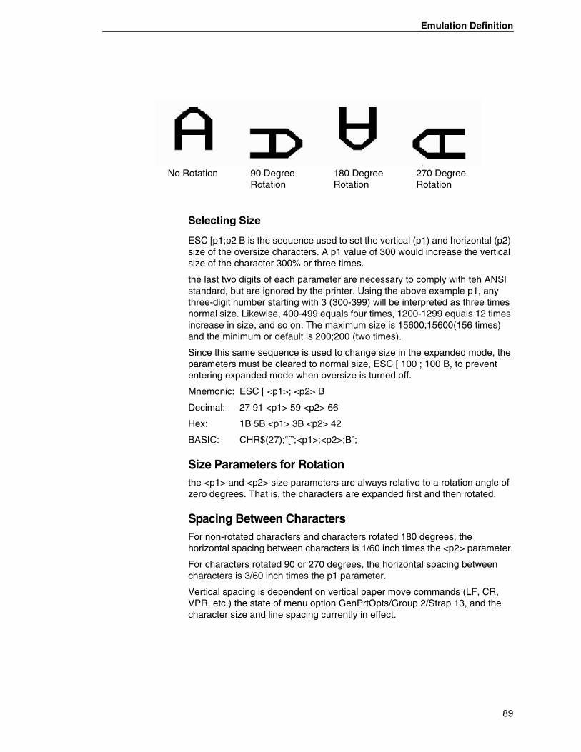
Emulation Definition
Selecting Size
ESC [p1;p2 B is the sequence used to set the vertical (p1) and horizontal (p2) size of the oversize characters. A p1 value of 300 would increase the vertical size of the character 300% or three times.
the last two digits of each parameter are necessary to comply with teh ANSI standard, but are ignored by the printer. Using the above example p1, any three-digit number starting with 3 (300-399) will be interpreted as three times normal size. Likewise, 400-499 equals four times, 1200-1299 equals 12 times increase in size, and so on. The maximum size is 15600;15600(156 times) and the minimum or default is 200;200 (two times).
Since this same sequence is used to change size in the expanded mode, the parameters must be cleared to normal size, ESC [ 100 ; 100 B, to prevent entering expanded mode when oversize is turned off.
Mnemonic: ESC [ <p1>; <p2> B
Decimal: 27 91 <p1> 59 <p2> 66
Hex: 1B 5B <p1> 3B <p2> 42
BASIC: CHR$(27);“[”;<p1>;<p2>;B”;
Size Parameters for Rotationthe <p1> and <p2> size parameters are always relative to a rotation angle of zero degrees. That is, the characters are expanded first and then rotated.
Spacing Between CharactersFor non-rotated characters and characters rotated 180 degrees, the horizontal spacing between characters is 1/60 inch times the <p2> parameter.
For characters rotated 90 or 270 degrees, the horizontal spacing between characters is 3/60 inch times the p1 parameter.
Vertical spacing is dependent on vertical paper move commands (LF, CR, VPR, etc.) the state of menu option GenPrtOpts/Group 2/Strap 13, and the character size and line spacing currently in effect.
No Rotation 90 Degree Rotation
180 Degree Rotation
270 Degree Rotation
89
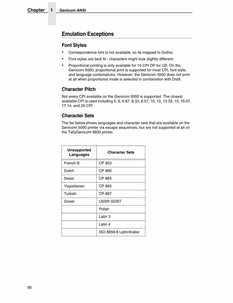
Chapter 1 Genicom ANSI
Emulation Exceptions
Font Styles• Correspondence font is not available, so its mapped to Gothic.
• Font styles are best fit - characters might look slightly different.
• Proportional printing is only available for 10 CPI DP for US. On the Genicom 5000, proportional print is supported for most CPI, font style, and language combinations. However, the Genicom 5000 does not print at all when proportional mode is selected in combination with Draft.
Character PitchNot every CPI available on the Genicom 5000 is supported. The closest available CPI is used including 5, 6, 6.67, 8.33, 8.57, 10, 12, 13.33, 15, 16.67, 17.14, and 20 CPI.
Character SetsThe list below shows languages and character sets that are available on the Genicom 5000 printer via escape sequences, but are not supported at all on the TallyGenicom 6600 printer.
Unsupported Languages
Character Sets
French B CP 853
Dutch CP 860
Swiss CP 864
Yugoslavian CP 865
Turkish CP 867
Greek USSR GOST
Polish
Latin 3
Latin 4
ISO 8859-6 Latin/Arabic
90
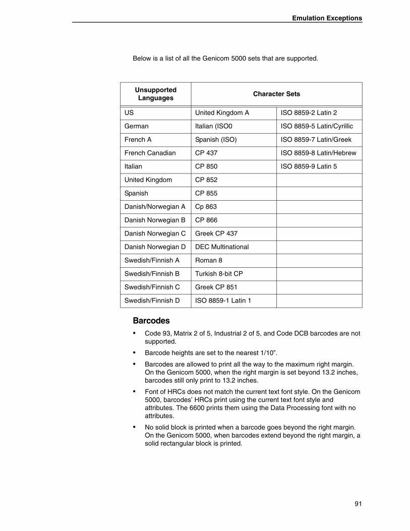
Emulation Exceptions
Below is a list of all the Genicom 5000 sets that are supported.
Barcodes• Code 93, Matrix 2 of 5, Industrial 2 of 5, and Code DCB barcodes are not
supported.
• Barcode heights are set to the nearest 1/10”.
• Barcodes are allowed to print all the way to the maximum right margin. On the Genicom 5000, when the right margin is set beyond 13.2 inches, barcodes still only print to 13.2 inches.
• Font of HRCs does not match the current text font style. On the Genicom 5000, barcodes’ HRCs print using the current text font style and attributes. The 6600 prints them using the Data Processing font with no attributes.
• No solid block is printed when a barcode goes beyond the right margin. On the Genicom 5000, when barcodes extend beyond the right margin, a solid rectangular block is printed.
Unsupported Languages
Character Sets
US United Kingdom A ISO 8859-2 Latin 2
German Italian (ISO0 ISO 8859-5 Latin/Cyrillic
French A Spanish (ISO) ISO 8859-7 Latin/Greek
French Canadian CP 437 ISO 8859-8 Latin/Hebrew
Italian CP 850 ISO 8859-9 Latin 5
United Kingdom CP 852
Spanish CP 855
Danish/Norwegian A Cp 863
Danish Norwegian B CP 866
Danish Norwegian C Greek CP 437
Danish Norwegian D DEC Multinational
Swedish/Finnish A Roman 8
Swedish/Finnish B Turkish 8-bit CP
Swedish/Finnish C Greek CP 851
Swedish/Finnish D ISO 8859-1 Latin 1
91
Chapter 1 Printronix P5000
Block CharactersBlock characters are allowed to print all the way to the maximum right margin. On the Genicom 5000, when the right margin is set beyond 13.2 inches, block characters still only print 13.2 inches.
Emulation Enhancements
The following escape sequences have been added:
POSTNET barcodes ESC [ 50 ; ... }
PLANET barcodes ESC [ 53 ; ... }
Printronix P5000The Printronix P5000 emulation is defined by LinePrinter Plus for Line Matrix Printers Programmer’s Reference Manual. The chapter on P-Series Printer Emulation was used. The following exceptions exist:
1. <SFCC>c Download New Character Shape - not supported.
2. <SFCC>V Download a Character Set Overlay - not supported.
3. Basic character set select on the panel is not supported. <SFCC>PSET;n and <SFCC>Rn react differently based on which basic character set is selected on the panel of the Printronix printer. Since we don’t have this panel setting, we assume the basic character set to be ECMA Latin 1.
4. <SFCC>lxyz and <SFCC>OSET;n offer characters that our printer does not support, including barcode, Greek, graphics and scientific.
5. Some of the character set mappings supported by <SFCC>lxyz do not match exactly the character mappings supported by our printer. In these cases, the closest match was selected.
6. <SFCC>PMODE;n allows DP text at various CPIs to be printed upside down. This feature is not supported.
Printronix P6000The Printronix P6000 emulation is defined by P6000 Series Multifunctional Line printer Pedestal Models.
With the exception of one control code (Hex 01), the P6000 emulation is a superset of the P600 emulation. The additional features are similar to those found in Epson and Proprinter emulations. Specific differences are as follows:
1. Printronix does not implement the alternate character set and the 6600 Series P6000 Emulation does.
2. 6600 Series P6000 Emulation can change the alternate character set with the panel to Latin 2.
3. Printronix P6000 manual does not mention 08 hex for elongated text from the P600 emulation. P6000 and 6600 Series P6000 Emulation both accept 08 hex and 0164 hex to elongate text.
92
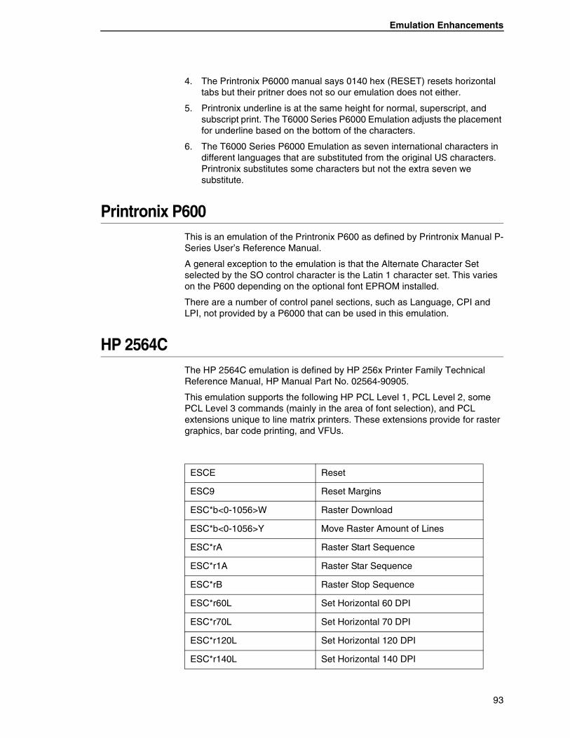
Emulation Enhancements
4. The Printronix P6000 manual says 0140 hex (RESET) resets horizontal tabs but their pritner does not so our emulation does not either.
5. Printronix underline is at the same height for normal, superscript, and subscript print. The T6000 Series P6000 Emulation adjusts the placement for underline based on the bottom of the characters.
6. The T6000 Series P6000 Emulation as seven international characters in different languages that are substituted from the original US characters. Printronix substitutes some characters but not the extra seven we substitute.
Printronix P600This is an emulation of the Printronix P600 as defined by Printronix Manual P-Series User’s Reference Manual.
A general exception to the emulation is that the Alternate Character Set selected by the SO control character is the Latin 1 character set. This varies on the P600 depending on the optional font EPROM installed.
There are a number of control panel sections, such as Language, CPI and LPI, not provided by a P6000 that can be used in this emulation.
HP 2564CThe HP 2564C emulation is defined by HP 256x Printer Family Technical Reference Manual, HP Manual Part No. 02564-90905.
This emulation supports the following HP PCL Level 1, PCL Level 2, some PCL Level 3 commands (mainly in the area of font selection), and PCL extensions unique to line matrix printers. These extensions provide for raster graphics, bar code printing, and VFUs.
ESCE Reset
ESC9 Reset Margins
ESC*b<0-1056>W Raster Download
ESC*b<0-1056>Y Move Raster Amount of Lines
ESC*rA Raster Start Sequence
ESC*r1A Raster Star Sequence
ESC*rB Raster Stop Sequence
ESC*r60L Set Horizontal 60 DPI
ESC*r70L Set Horizontal 70 DPI
ESC*r120L Set Horizontal 120 DPI
ESC*r140L Set Horizontal 140 DPI
93
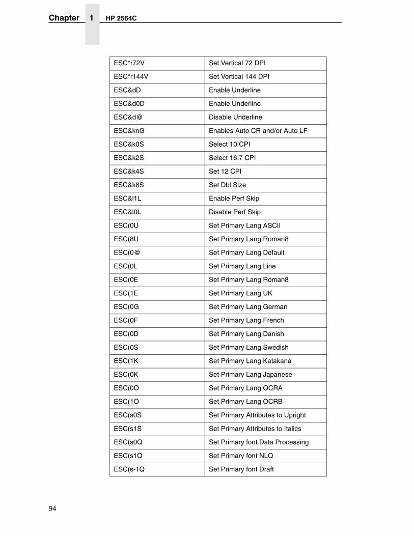
Chapter 1 HP 2564C
ESC*r72V Set Vertical 72 DPI
ESC*r144V Set Vertical 144 DPI
ESC&dD Enable Underline
ESC&d0D Enable Underline
ESC&d@ Disable Underline
ESC&knG Enables Auto CR and/or Auto LF
ESC&k0S Select 10 CPI
ESC&k2S Select 16.7 CPI
ESC&k4S Set 12 CPI
ESC&k8S Set Dbl Size
ESC&l1L Enable Perf Skip
ESC&l0L Disable Perf Skip
ESC(0U Set Primary Lang ASCII
ESC(8U Set Primary Lang Roman8
ESC(0@ Set Primary Lang Default
ESC(0L Set Primary Lang Line
ESC(0E Set Primary Lang Roman8
ESC(1E Set Primary Lang UK
ESC(0G Set Primary Lang German
ESC(0F Set Primary Lang French
ESC(0D Set Primary Lang Danish
ESC(0S Set Primary Lang Swedish
ESC(1K Set Primary Lang Katakana
ESC(0K Set Primary Lang Japanese
ESC(0O Set Primary Lang OCRA
ESC(1O Set Primary Lang OCRB
ESC(s0S Set Primary Attributes to Upright
ESC(s1S Set Primary Attributes to Italics
ESC(s0Q Set Primary font Data Processing
ESC(s1Q Set Primary font NLQ
ESC(s-1Q Set Primary font Draft
94
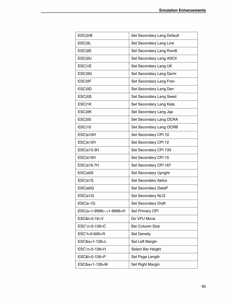
Emulation Enhancements
ESC)0@ Set Secondary Lang Default
ESC)0L Set Secondary Lang Line
ESC)0E Set Secondary Lang Rom8
ESC)0U Set Secondary Lang ASCII
ESC)1E Set Secondary Lang UK
ESC)0G Set Secondary Lang Germ
ESC)0F Set Secondary Lang Fren
ESC)0D Set Secondary Lang Den
ESC)0S Set Secondary Lang Swed
ESC)1K Set Secondary Lang Kata
ESC)0K Set Secondary Lang Jap
ESC)00 Set Secondary Lang OCRA
ESC)10 Set Secondary Lang OCRB
ESC)s10H Set Secondary CPI 10
ESC)s12H Set Secondary CPI 12
ESC)s13.3H Set Secondary CPI 133
ESC)s15H Set Secondary CPI 15
ESC)s16.7H Set Secondary CPI 167
ESC)s0S Set Secondary Upright
ESC)s1S Set Secondary Italics
ESC)s0Q Set Secondary DataP
ESC)s1Q Set Secondary NLQ
ESC)s-1Q Set Secondary Draft
ESC(s<1-9999>.<1-9999>H Set Primary CPI
ESC&l<0-16>V Do VFU Move
ESC*z<0-128>C Bar Column Size
ESC*t<0-600>R Set Density
ESC&a<1-128>L Set Left Margin
ESC*z<0-128>H Select Bar Height
ESC&l<0-128>P Set Page Length
ESC&a<1-128>M Set Right Margin
95
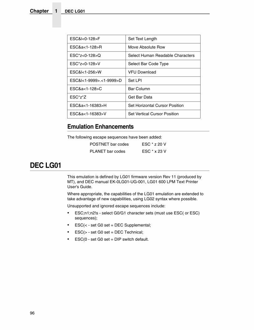
Chapter 1 DEC LG01
Emulation Enhancements
The following escape sequences have been added:
POSTNET bar codes ESC * z 20 V
PLANET bar codes ESC * x 23 V
DEC LG01This emulation is defined by LG01 firmware version Rev 11 (produced by MT), and DEC manual EK-0LG01-UG-001, LG01 600 LPM Text Printer User's Guide.
Where appropriate, the capabilities of the LG01 emulation are extended to take advantage of new capabilities, using LG02 syntax where possible.
Unsupported and ignored escape sequences include:
• ESC;n1;n2!s - select G0/G1 character sets (must use ESC( or ESC) sequences);
• ESC(< - set G0 set = DEC Supplemental;
• ESC(> - set G0 set = DEC Technical;
• ESC(0 - set G0 set = DIP switch default.
ESC&l<0-128>F Set Text Length
ESC&a<1-128>R Move Absolute Row
ESC*z<0-128>Q Select Human Readable Characters
ESC*z<0-128>V Select Bar Code Type
ESC&l<1-256>W VFU Download
ESC&l<1-9999>.<1-9999>D Set LPI
ESC&a<1-128>C Bar Column
ESC*z*Z Get Bar Data
ESC&a<1-16383>H Set Horizontal Cursor Position
ESC&a<1-16383>V Set Vertical Cursor Position
96
Emulation Enhancements
Epson FX-1180Prior to Firmware Version 2.1 of the T6200 Series printers, the Epson FX-100+ was emulated as defined by Epson document P8294017A, FX+ Series Printer User's Manual. Exceptions and enhancements were the same as those for the Proprinter emulation.
Effective in Firmware Version 2.1, the Epson FX-100+ emulation was enhanced to emulate the more current FX-1180. This emulation is defined in the Epson ESC/P Reference Manual. The version of the manual used for the emulation development was date December 1997.
In order to support the FX-1180, the following escape sequences were added to the FX-100+ emulation:
Page Format: ESC ( C – Set Page Length in Defined Units ESC ( c – Set Page Format
Print Position Motion: ESC \ - Set Relative Horizontal Print Position
Spacing: ESC <space> - Set Intercharacter Space
Bar Codes: ESC ( B – Select Bar Code Printing
All of the Epson barcodes are supported, including:
Code 39 EAN-8 UPC-A
Interleaved 2 of 5 EAN-13 UPC-E
POSTNET Code 128
97
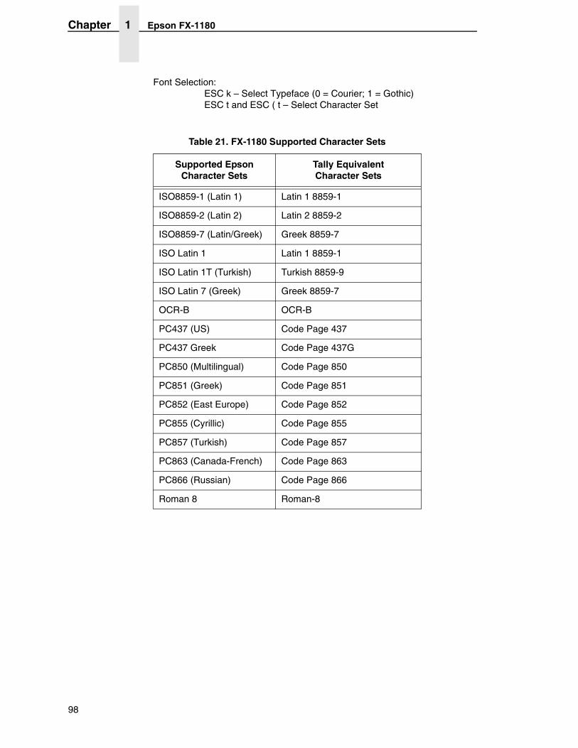
Chapter 1 Epson FX-1180
Font Selection: ESC k – Select Typeface (0 = Courier; 1 = Gothic) ESC t and ESC ( t – Select Character Set
Table 21. FX-1180 Supported Character Sets
Supported Epson Character Sets
Tally Equivalent Character Sets
ISO8859-1 (Latin 1) Latin 1 8859-1
ISO8859-2 (Latin 2) Latin 2 8859-2
ISO8859-7 (Latin/Greek) Greek 8859-7
ISO Latin 1 Latin 1 8859-1
ISO Latin 1T (Turkish) Turkish 8859-9
ISO Latin 7 (Greek) Greek 8859-7
OCR-B OCR-B
PC437 (US) Code Page 437
PC437 Greek Code Page 437G
PC850 (Multilingual) Code Page 850
PC851 (Greek) Code Page 851
PC852 (East Europe) Code Page 852
PC855 (Cyrillic) Code Page 855
PC857 (Turkish) Code Page 857
PC863 (Canada-French) Code Page 863
PC866 (Russian) Code Page 866
Roman 8 Roman-8
98
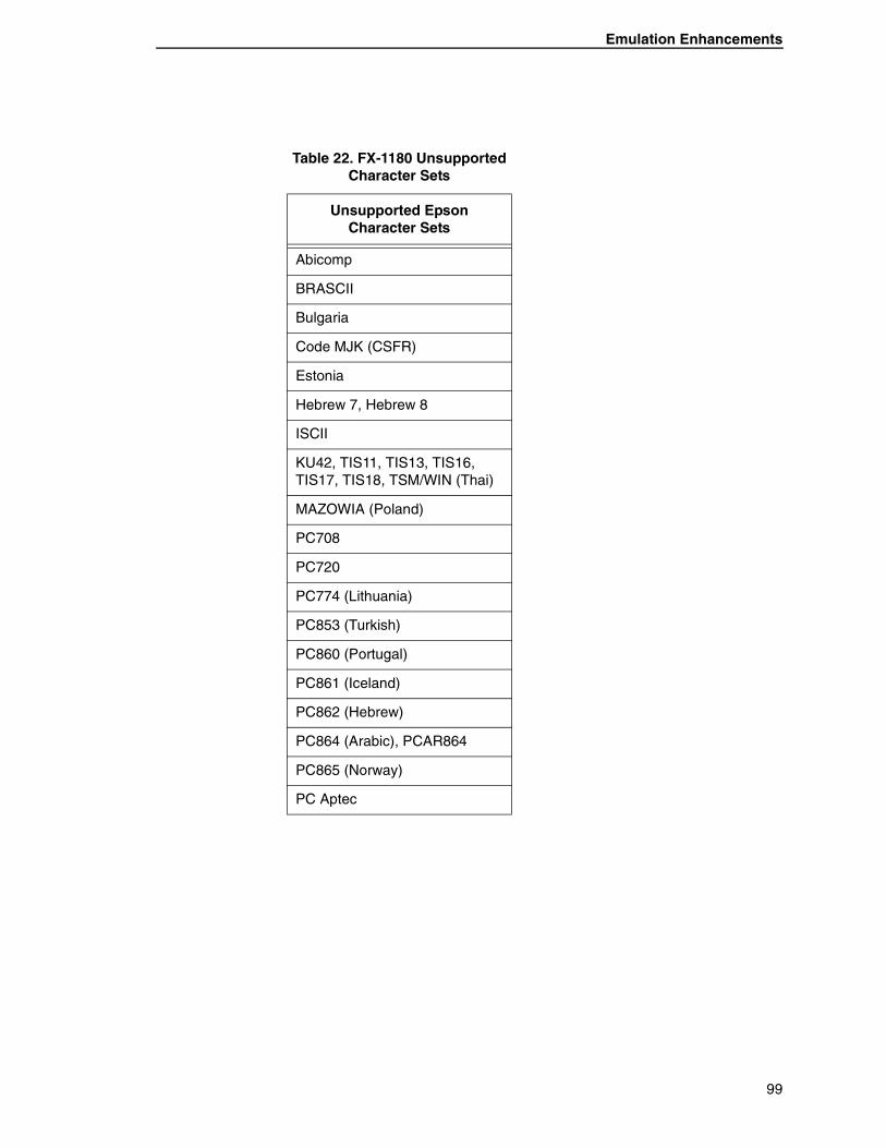
Emulation Enhancements
Table 22. FX-1180 Unsupported Character Sets
Unsupported Epson Character Sets
Abicomp
BRASCII
Bulgaria
Code MJK (CSFR)
Estonia
Hebrew 7, Hebrew 8
ISCII
KU42, TIS11, TIS13, TIS16, TIS17, TIS18, TSM/WIN (Thai)
MAZOWIA (Poland)
PC708
PC720
PC774 (Lithuania)
PC853 (Turkish)
PC860 (Portugal)
PC861 (Iceland)
PC862 (Hebrew)
PC864 (Arabic), PCAR864
PC865 (Norway)
PC Aptec
99
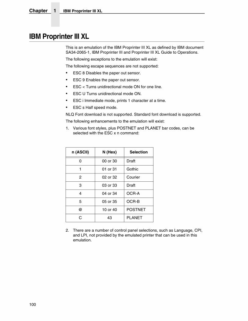
Chapter 1 IBM Proprinter III XL
IBM Proprinter III XLThis is an emulation of the IBM Proprinter III XL as defined by IBM document SA34-2065-1, IBM Proprinter III and Proprinter III XL Guide to Operations.
The following exceptions to the emulation will exist:
The following escape sequences are not supported:
• ESC 8 Disables the paper out sensor.
• ESC 9 Enables the paper out sensor.
• ESC < Turns unidirectional mode ON for one line.
• ESC U Turns unidirectional mode ON.
• ESC i Immediate mode, prints 1 character at a time.
• ESC s Half speed mode.
NLQ Font download is not supported. Standard font download is supported.
The following enhancements to the emulation will exist:
1. Various font styles, plus POSTNET and PLANET bar codes, can be selected with the ESC x n command:
2. There are a number of control panel selections, such as Language, CPI, and LPI, not provided by the emulated printer that can be used in this emulation.
n (ASCII) N (Hex) Selection
0 00 or 30 Draft
1 01 or 31 Gothic
2 02 or 32 Courier
3 03 or 33 Draft
4 04 or 34 OCR-A
5 05 or 35 OCR-B
@ 10 or 40 POSTNET
C 43 PLANET
100
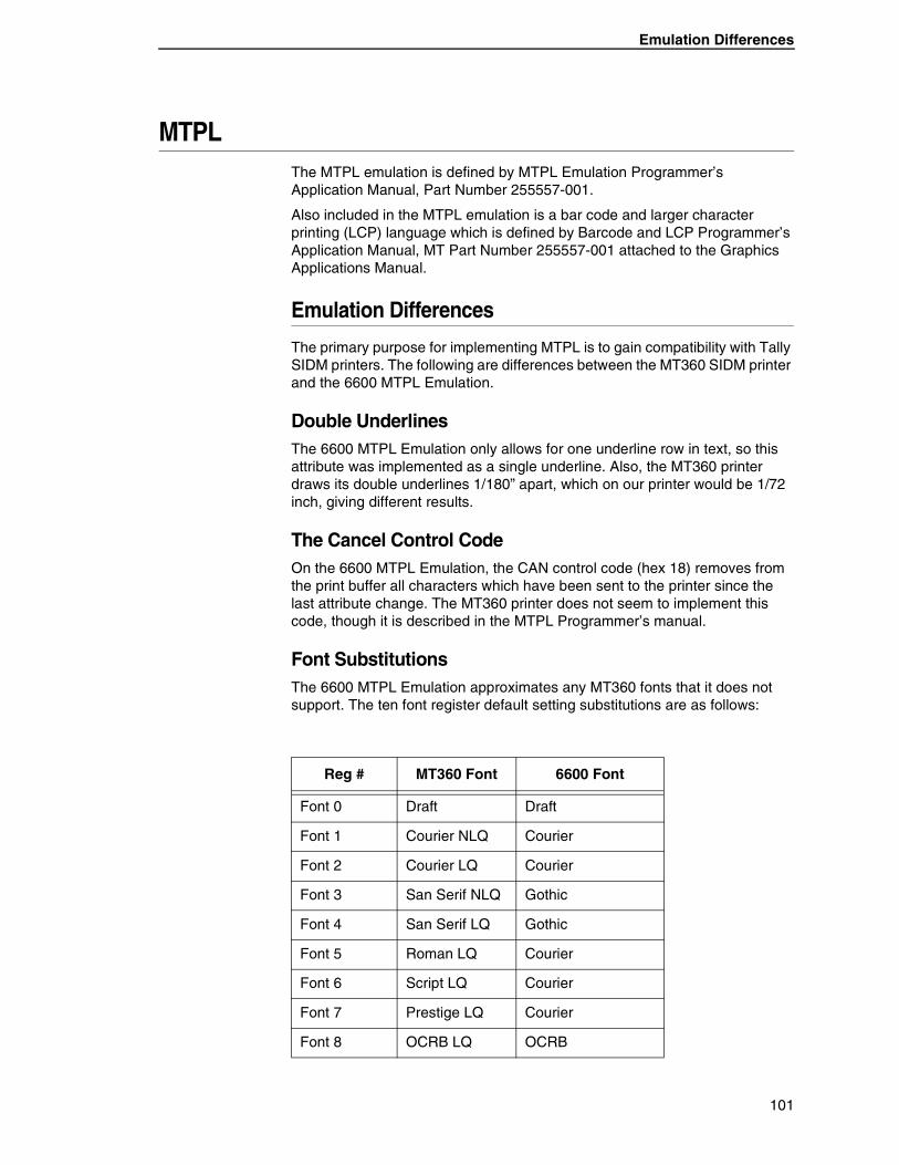
Emulation Differences
MTPLThe MTPL emulation is defined by MTPL Emulation Programmer’s Application Manual, Part Number 255557-001.
Also included in the MTPL emulation is a bar code and larger character printing (LCP) language which is defined by Barcode and LCP Programmer’s Application Manual, MT Part Number 255557-001 attached to the Graphics Applications Manual.
Emulation Differences
The primary purpose for implementing MTPL is to gain compatibility with Tally SIDM printers. The following are differences between the MT360 SIDM printer and the 6600 MTPL Emulation.
Double UnderlinesThe 6600 MTPL Emulation only allows for one underline row in text, so this attribute was implemented as a single underline. Also, the MT360 printer draws its double underlines 1/180” apart, which on our printer would be 1/72 inch, giving different results.
The Cancel Control CodeOn the 6600 MTPL Emulation, the CAN control code (hex 18) removes from the print buffer all characters which have been sent to the printer since the last attribute change. The MT360 printer does not seem to implement this code, though it is described in the MTPL Programmer’s manual.
Font SubstitutionsThe 6600 MTPL Emulation approximates any MT360 fonts that it does not support. The ten font register default setting substitutions are as follows:
Reg # MT360 Font 6600 Font
Font 0 Draft Draft
Font 1 Courier NLQ Courier
Font 2 Courier LQ Courier
Font 3 San Serif NLQ Gothic
Font 4 San Serif LQ Gothic
Font 5 Roman LQ Courier
Font 6 Script LQ Courier
Font 7 Prestige LQ Courier
Font 8 OCRB LQ OCRB
101
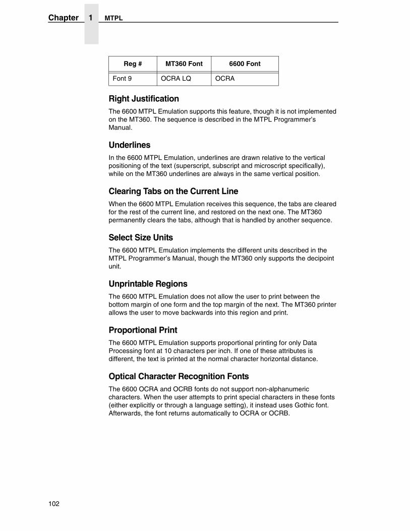
Chapter 1 MTPL
Right JustificationThe 6600 MTPL Emulation supports this feature, though it is not implemented on the MT360. The sequence is described in the MTPL Programmer’s Manual.
UnderlinesIn the 6600 MTPL Emulation, underlines are drawn relative to the vertical positioning of the text (superscript, subscript and microscript specifically), while on the MT360 underlines are always in the same vertical position.
Clearing Tabs on the Current LineWhen the 6600 MTPL Emulation receives this sequence, the tabs are cleared for the rest of the current line, and restored on the next one. The MT360 permanently clears the tabs, although that is handled by another sequence.
Select Size UnitsThe 6600 MTPL Emulation implements the different units described in the MTPL Programmer’s Manual, though the MT360 only supports the decipoint unit.
Unprintable RegionsThe 6600 MTPL Emulation does not allow the user to print between the bottom margin of one form and the top margin of the next. The MT360 printer allows the user to move backwards into this region and print.
Proportional PrintThe 6600 MTPL Emulation supports proportional printing for only Data Processing font at 10 characters per inch. If one of these attributes is different, the text is printed at the normal character horizontal distance.
Optical Character Recognition FontsThe 6600 OCRA and OCRB fonts do not support non-alphanumeric characters. When the user attempts to print special characters in these fonts (either explicitly or through a language setting), it instead uses Gothic font. Afterwards, the font returns automatically to OCRA or OCRB.
Font 9 OCRA LQ OCRA
Reg # MT360 Font 6600 Font
102
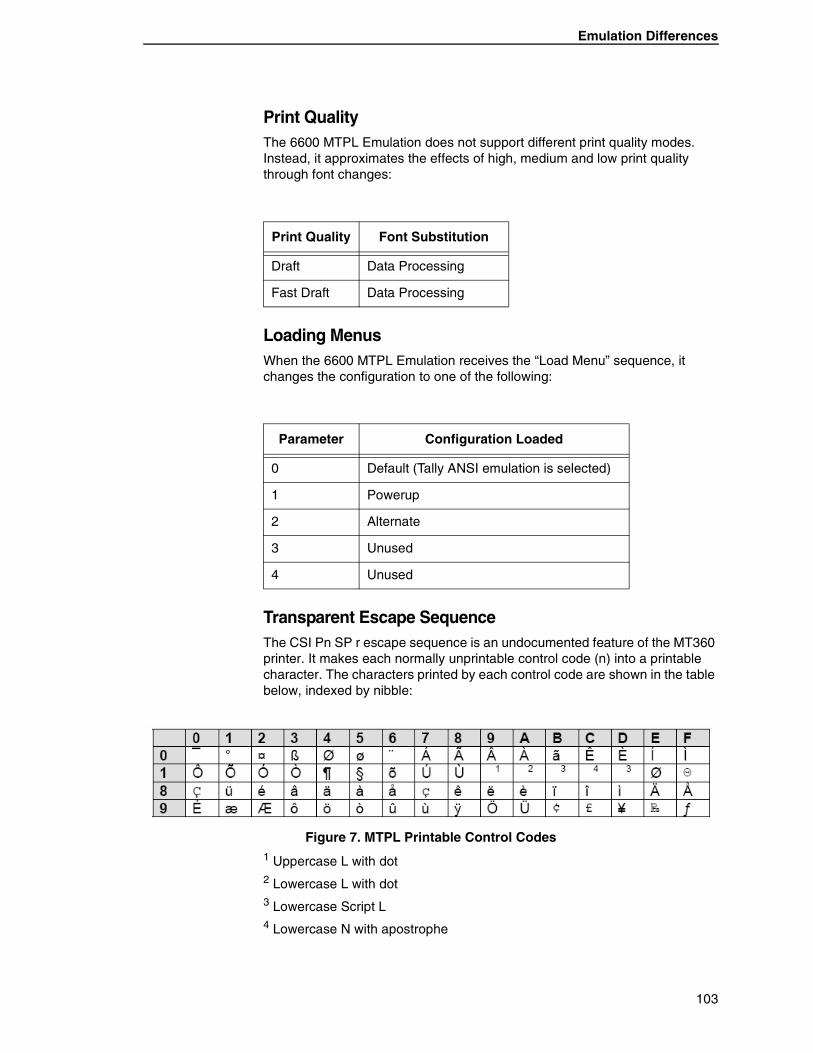
Emulation Differences
Print QualityThe 6600 MTPL Emulation does not support different print quality modes. Instead, it approximates the effects of high, medium and low print quality through font changes:
Loading MenusWhen the 6600 MTPL Emulation receives the “Load Menu” sequence, it changes the configuration to one of the following:
Transparent Escape SequenceThe CSI Pn SP r escape sequence is an undocumented feature of the MT360 printer. It makes each normally unprintable control code (n) into a printable character. The characters printed by each control code are shown in the table below, indexed by nibble:
Figure 7. MTPL Printable Control Codes1 Uppercase L with dot2 Lowercase L with dot3 Lowercase Script L4 Lowercase N with apostrophe
Print Quality Font Substitution
Draft Data Processing
Fast Draft Data Processing
Parameter Configuration Loaded
0 Default (Tally ANSI emulation is selected)
1 Powerup
2 Alternate
3 Unused
4 Unused
103
Chapter 1 PJL
Emulation Enhancements
The following escape sequences have been added:
POSTNET bar codes ESC [ 1 p
PLANET bar codes ESC [ 2 p
UK Postal 4-State bar codes ESC [ 1 k
Dutch KIX 4-State bar codes ESC [ 2 k
PJLA number of PJL commands have been implemented for use with all emulations except HP2564C when using the LANPlex interface. The primary use for PJL in this firmware is for AS/400 LAN attachment, or other custom applications. The LJ Series line printers should be used for full-featured connectivity in HP environments.
These commands are defined by Printer Job Language Technical Reference Manual, HP Part Number 5961-0938, May 1996. The following PJL commands are supported.
Universal Exit Language (UEL) Commands:
"ESC"%-12345X@PJL "ESC"%-12345X @PJL
ECHO Command:
@PJL ECHO
EOJ (End of Job) Commands:
@PJL EOJ @PJL EOJ NAME=
INFO (Information Request) Command:
@PJL INFO STATUS
RDYMSG (Ready Message) Command:
@PJL RDYMSG DISPLAY =
USTATUS (Unsolicited Status) Commands:
@PJL USTATUS DEVICE = ON @PJL USTATUS DEVICE = OFF @PJL USTATUS DEVICE = VERBOSE @PJL USTATUS JOB = ON @PJL USTATUS JOB = OFF @PJL USTATUS PAGE = ON @PJL USTATUS PAGE = OFF @PJL USTATUSOFF
104

Emulation Enhancements
JOB (Start of Job) Commands:
@PJL JOB NAME = @PJL JOB FILE = @PJL JOB START = @PJL JOB END = @PJL JOB COPY =
105

Chapter 1 PJL
106
2 Graphics Language
Emulations
Graphics languages are a set of commands used to create graphic images such as large characters, lines, boxes, and bar codes. A graphics language in the 6600 Series software is run on top of one or more underlying control languages.
MT660 Industrial GraphicsThis graphics language is an emulation of the MT660 Industrial Graphics option, as defined by MT Manual Number 243, Bar Code/Block Character Applications Manual. It is accessible only from the native ANSI emulation. The commands are defined in Manual Number 255557-001, Graphics Applications Manual, Line Printers.
QMS Code VThis graphics language is an emulation of QMS Code V Version 1 and 2. It is accessible from all underlying control languages.
The emulation is based on QMS Manual Number 1720155B, QMS Code V Version II Programming Manual. The commands are defined in Manual Number 255557-001, Graphics Applications Manual, Line Printers.
Printronix Graphics LanguageThe Printronix Graphics Language (PGL) emulation provides a graphics language that is compatible with the Printronix IGP 100/200/400 language. It is accessible from all underlying control languages.
The emulation is based on IGP-100 Firmware Version 2.19A (Part Number 148771,) and the Printronix IGP-100 Manual (Part Number 141331-001 Revision A.) In cases where the function of the firmware differs from the manual, the emulation follows the function of the firmware. The commands are defined in Manual Number 255557-001, Graphics Applications Manual, Line Printers.
107

Chapter 2 Printronix Graphics Language
108
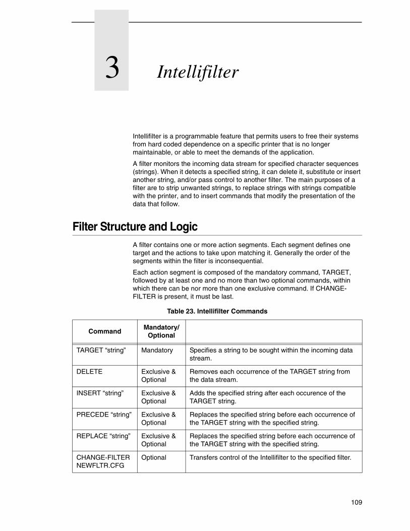
3 Intellifilter
Intellifilter is a programmable feature that permits users to free their systems from hard coded dependence on a specific printer that is no longer maintainable, or able to meet the demands of the application.
A filter monitors the incoming data stream for specified character sequences (strings). When it detects a specified string, it can delete it, substitute or insert another string, and/or pass control to another filter. The main purposes of a filter are to strip unwanted strings, to replace strings with strings compatible with the printer, and to insert commands that modify the presentation of the data that follow.
Filter Structure and LogicA filter contains one or more action segments. Each segment defines one target and the actions to take upon matching it. Generally the order of the segments within the filter is inconsequential.
Each action segment is composed of the mandatory command, TARGET, followed by at least one and no more than two optional commands, within which there can be nor more than one exclusive command. If CHANGE-FILTER is present, it must be last.
Table 23. Intellifilter Commands
CommandMandatory/
Optional
TARGET “string” Mandatory Specifies a string to be sought within the incoming data stream.
DELETE Exclusive & Optional
Removes each occurrence of the TARGET string from the data stream.
INSERT “string” Exclusive & Optional
Adds the specified string after each occurence of the TARGET string.
PRECEDE “string” Exclusive & Optional
Replaces the specified string before each occurrence of the TARGET string with the specified string.
REPLACE “string” Exclusive & Optional
Replaces the specified string before each occurrence of the TARGET string with the specified string.
CHANGE-FILTER NEWFLTR.CFG
Optional Transfers control of the Intellifilter to the specified filter.
109
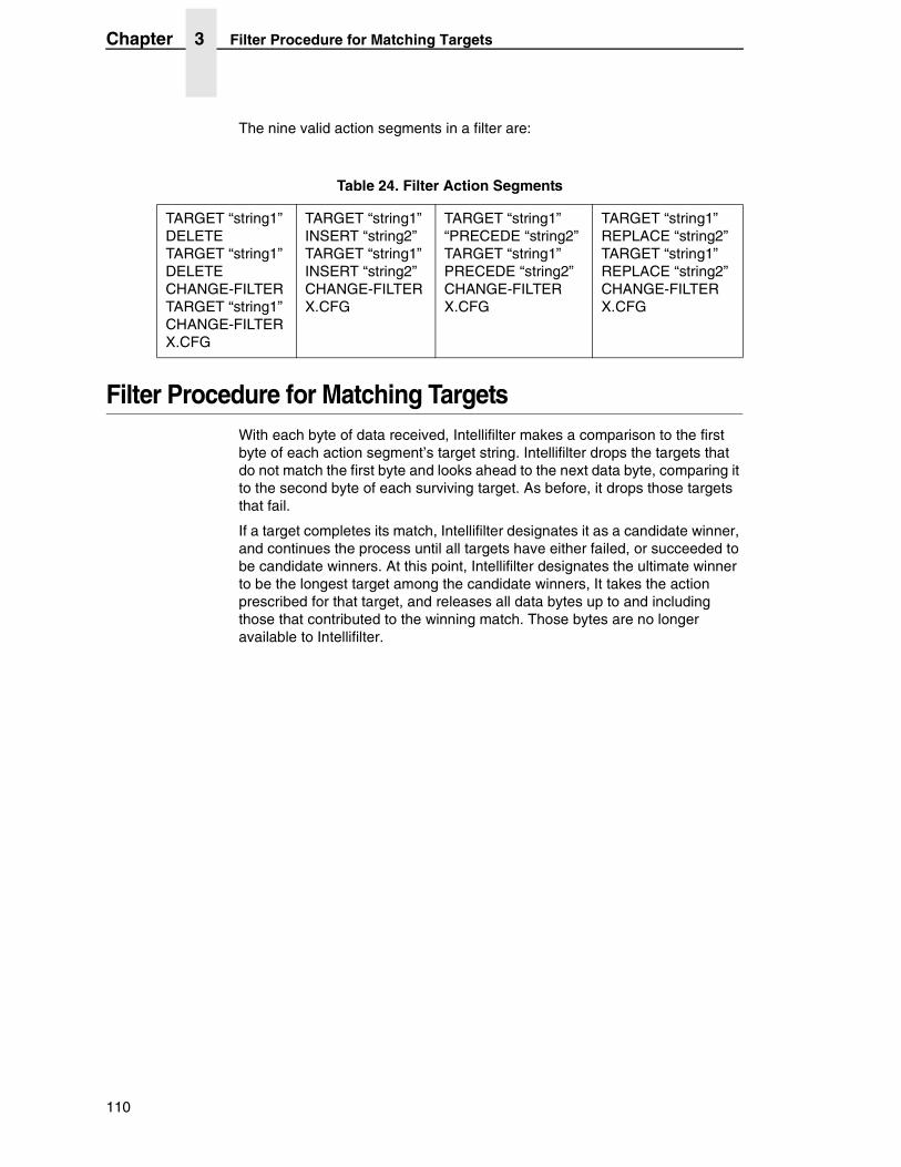
Chapter 3 Filter Procedure for Matching Targets
The nine valid action segments in a filter are:
Filter Procedure for Matching TargetsWith each byte of data received, Intellifilter makes a comparison to the first byte of each action segment’s target string. Intellifilter drops the targets that do not match the first byte and looks ahead to the next data byte, comparing it to the second byte of each surviving target. As before, it drops those targets that fail.
If a target completes its match, Intellifilter designates it as a candidate winner, and continues the process until all targets have either failed, or succeeded to be candidate winners. At this point, Intellifilter designates the ultimate winner to be the longest target among the candidate winners, It takes the action prescribed for that target, and releases all data bytes up to and including those that contributed to the winning match. Those bytes are no longer available to Intellifilter.
Table 24. Filter Action Segments
TARGET “string1” DELETE TARGET “string1” DELETE CHANGE-FILTER TARGET “string1” CHANGE-FILTER X.CFG
TARGET “string1” INSERT “string2” TARGET “string1” INSERT “string2” CHANGE-FILTER X.CFG
TARGET “string1” “PRECEDE “string2” TARGET “string1” PRECEDE “string2” CHANGE-FILTER X.CFG
TARGET “string1” REPLACE “string2” TARGET “string1” REPLACE “string2” CHANGE-FILTER X.CFG
110
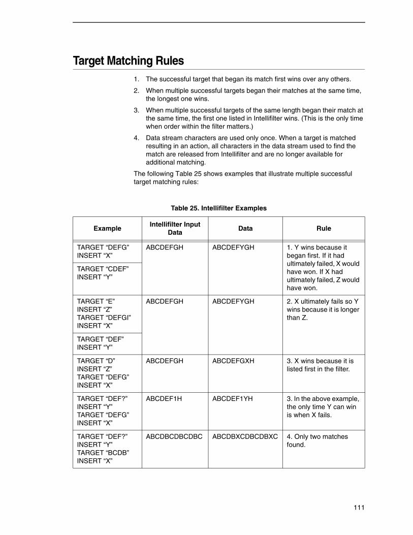
Target Matching Rules1. The successful target that began its match first wins over any others.
2. When multiple successful targets began their matches at the same time, the longest one wins.
3. When multiple successful targets of the same length began their match at the same time, the first one listed in Intellifilter wins. (This is the only time when order within the filter matters.)
4. Data stream characters are used only once. When a target is matched resulting in an action, all characters in the data stream used to find the match are released from Intellifilter and are no longer available for additional matching.
The following Table 25 shows examples that illustrate multiple successful target matching rules:
Table 25. Intellifilter Examples
ExampleIntellifilter Input
DataData Rule
TARGET “DEFG” INSERT “X”
ABCDEFGH ABCDEFYGH 1. Y wins because it began first. If it had ultimately failed, X would have won. If X had ultimately failed, Z would have won.
TARGET “CDEF” INSERT “Y”
TARGET “E” INSERT “Z” TARGET “DEFGI” INSERT “X”
ABCDEFGH ABCDEFYGH 2. X ultimately fails so Y wins because it is longer than Z.
TARGET “DEF” INSERT “Y”
TARGET “D” INSERT “Z” TARGET “DEFG” INSERT “X”
ABCDEFGH ABCDEFGXH 3. X wins because it is listed first in the filter.
TARGET “DEF?” INSERT “Y” TARGET “DEFG” INSERT “X”
ABCDEF1H ABCDEF1YH 3. In the above example, the only time Y can win is when X fails.
TARGET “DEF?” INSERT “Y” TARGET “BCDB” INSERT “X”
ABCDBCDBCDBC ABCDBXCDBCDBXC 4. Only two matches found.
111
Chapter 3 Building, Testing, and Implementing Intellifilter
Building, Testing, and Implementing Intellifilter1. Capture and analyze all data files that will be sent to the printer.
2. Design and write the filter files in a comprehensive text editor. Make sure the filter is sufficiently discriminating that it not only works correctly on the files that require action, but that it does not false on any other file that comes to the printer.
3. Test the filter against the captured data, using IFILTER.EXE, a DOS-based program that simulates the Intellifilter function of the printer. Verify the result by viewing the resulting output file in the editor, and/or by sending it to the printer.
When satisfied, install the Intellifilter in the printer as follows:
4. Make a command file that indicates whether the files are to go to flash or hard disk, and that names all the files in the suite.
5. Run BUILDLOD.EXE which reads the command file, and builds the composite OUTPUT.LOD file.
6. Set up the printer to accept an Intellifilter download (see Operator Manual) and send OUTPUT.LOD directly to the printer to install the filter suite.
7. Send the captured data files to the printer to verify correct operation.
IFILTER.EXE
By simulating the Intellifilter logic in the printer, IFILTER.EXE permits rapidly testing filter designs. IFILTER.EXE reads an Intellifilter file suite, plus a data file, and produces an output file based on the actions commanded. IFILTER.EXE runs under DOS on a PC. All input and output files are in the default (current) directory.
The output of IFILTER.EXE is IFILTER.OUT, a file which can be analyzed in a text editor, or sent to a printer to verify the result. IFILTER.EXE also reports status and errors related to the filtering operation. These include parsing of the configuration files as well as the actual data filtering.
The command is:
IFILTER MASTER-CONFIG-FILE DATA-STREAM-FILE (Y|N)
strip-ctrl-d: N = no (default, Y = yes
When the master configuration file is loaded into the printer, it must be named FMASTER.CFG, but a different name, for example TEST.CFG, can be used with IFILTER.EXE. Be sure either to rename or copy it to FMASTER.CFG before compiling it.
If the master configuration file calls other filter files, you do not need to name them. IFILTER.EXE will identify them by following all the chains.
DATA-STREAM-FILE is the name of the file to be acted upon. The contents of this file will be modified by the commands of the Intellifilter suite, and the result written in IFILTER.OUT.
112
BUILDLOD.EXE
BUILDLOD.EXE
BUILDLOD.EXE is a DOS-Based program that combines and compiles individual files into a single file, OUTPUT.LOD, which serves as a vehicle to directly transfer them into a TallyGenicom printer’s non-volatile storage.
The command is BUILDLOD FILELIST.CMD
1. The command file can have any name and extension, but usually is given a name related to the customer or application, and with a .CMD extension.
2. Files named in FILELIST.CMD will be processed by BUILDLOD.EXE and incorporated into OUTPUT.LOD
3. The main Intellifilter file must be named FMASTER.CFG.
Command File Structure:
FILELIST.CMD FORMAT TYPE OTHER INPUT CONTINUE.CFG
The FORMAT command is required if it is desired to format the flash file system prior to loading the files.
The TYPE OTHER indicates flash memory which is the only storage option for line printers.
113

Chapter 3 Building, Testing, and Implementing Intellifilter
114
A Customer Support
TallyGenicom Customer Support Center
IMPORTANT Please have the following information available prior to calling the TallyGenicom Customer Support Center:
• Model number
• Serial number (located on the back of the printer)
• Installed options (i.e., interface and host type if applicable to the problem)
• Go to the Help Menu on the control panel menu, then press the MENU/ENTER key to print a configuration report.
• Is the problem with a new install or an existing printer?
• Description of the problem (be specific)
• Good and bad samples that clearly show the problem (faxing of these samples may be required)
Americas (714) 368-2686
Europe, Middle East, and Africa (31) 24 6489 311
Asia Pacific (65) 6548 4114
China (86) 800-999-6836
http://www.tallygenicom.com/service/default.aspx
TallyGenicom Supplies DepartmentContact the TallyGenicom Supplies Department for genuine TallyGenicom supplies.
Americas (800) 733-1900
Europe, Middle East, and Africa 33 (0) 1 46 25 19 07
Asia Pacific (65) 6548 4116 or (65) 6548 4182
China (86) 400-886-5598
http://www.tallygenicom.com/supplies/default.aspx
115
Appendix A Corporate Offices
Corporate OfficesPrintronix, Inc. 14600 Myford Road P.O. Box 19559 Irvine, CA 92623-9559 Phone: (714) 368-2300 Fax: (714) 368-2600
Printronix, Inc. Nederland BV P.O. Box 163, Nieuweweg 283 NL-6600 Ad Wijchen The Netherlands Phone: (31) 24 6489489 Fax: (31) 24 6489499
Printronix Schweiz GmbH 42 Changi South Street 1 Changi South Industrial Estate Singapore 486763 Phone: (65) 6542 0110 Fax: (65) 6546 1588
Printronix Commercial (Shanghai) Co. Ltd 22F, Eton Building East No.555, Pudong Av. Shanghai City, 200120, P R China Phone: (86) 400 886 5598 Fax: (86-21) 5138 0564
Visit the web site at www.tallygenicom.com
116
Index
A
Alternate Escape Sequences, 49
ANSI Escape Sequence Categories, 62
B
Bar Codes, Genicom ANSI Emulation, 85
Barcodes, Genicom ANSI Emulation Exceptions, 91
Block Characters, Genicom ANSI Emulation
Exceptions, 92
Building Intellifilter, 112
BUILDOD.EXE, 113
C
Cancel Control Code, MTPL Emulation Differences, 101
Character Definition, Tally ANSI, 9
Character Format, Tally ANSI, 9
Character Pitch, Genicom ANSI Emulation
Exceptions, 90
Character Sets, Genicom ANSI Emulation
Exceptions, 90
Clearing Tabs on Current Line, MTPL Emulation
Differences, 102
Configuration Switching, 51
Control Language Emulations, 7
DEC LG01, 96
Epson FX-1180, 97
Genicom ANSI, 56
HP 2564C, 93
IBM Proprinter III XL, 100
MTPL, 101
PJL, 104
Printronix P5000, 92
Printronix P600, 93
Printronix P6000, 92
Tally ANSI, 9
Custom Message Display, 48
Customer Support Center, 115
D
DEC LG01, 96
Double Underlines, MTPL Emulation Differences, 101
E
Emulation Definition, Genicom ANSI, 56
Emulation Differences, MTPL, 101
Emulation Enhancements, Genicom ANSI, 92
Emulation Enhancements, HP 2564C, 96
Emulation Enhancements, MTPL, 104
Emulation Exceptions, Genicom ANSI, 90
Emulation Switching, 51
Epson FX-1180, 97
Escape Sequence Directory, Genicom ANSI, 60
Escape Sequence Summary, 53
EVFU, Genicom ANSI Emulation, 81
F
Font Styles, Genicom ANSI Emulation Exceptions, 90
Font Substitutions, MTPL Emulation Differences, 101
Forward Index, 35
117
G
Genicom ANSI, 56
emulation definition, 56
emulation enhancements, 92
emulation exceptions, 90
Genicom ANSI Emulation Definition, 56
ANSI escape sequence categories, 62
bar codes, 85
control code, 56
control code definitions, 58
escape sequence activity levels, 56
escape sequence directory, 60
EVFU, 81
graphics, 75
oversize character font, 88
size parameters for rotation, 89
spacing between characters, 89
Genicom ANSI Emulation Exceptions
barcodes, 91
block characters, 92
character pitch, 90
character sets, 90
font styles, 90
Graphics Language Emulations, 107
MT660 Industrial Graphics, 107
Printronix Graphics Language, 107
QMS Code V, 107
Graphics, Genicom ANSI Emulation, 75
H
HP 2564C, 93
emulation enhancements, 96
I
IBM Proprinter III XL, 100
IFILTER.EXE, 112
Implementing Intellifilter, 112
Intellifilter, 109
building, 112
filter procedure for matching targets, 110
filter structure, 109
implementing, 112
logic, 109
target matching rules, 111
testing, 112
L
Loading Menus, MTPL Emulation Differences, 103
M
MT660 Industrial Graphics, 107
MTPL, 101
emulation differences, 101
emulation enhancements, 104
MTPL Emulation Differences
cancel control code, 101
clearing tabs on current line, 102
double underlines, 101
font substitutions, 101
loading menus, 103
optical character recogition fonts, 102
print quality, 103
proportional print, 102
right justification, 102
select size units, 102
transparent escape sequence, 103
underlines, 102
unprintable regions, 102
O
Optical Character Recognition Fonts, MTPL
Emulation Differences, 102
Oversize Character Font, Genicom ANSI
Emulation, 88
P
Page Formatting, Tally ANSI, 25
Partial Line Advance, 36
PJL, 104
PLANET Bar Codes, 50
Plot Data, 40
Plot Density, 47
Plot Mode Commands, 38
Plotting Dot Patterns, 42
POSTNET Bar Codes, 49
Print Quality, MTPL Emulation Differences, 103
118
Printronix
P5000, 92
P600, 93
P6000, 92
Printronix Graphics Language, 107
Proportional Print, MTPL Emulation Differences, 102
Q
QMS Code V, 107
R
Relative Paper Motion, 34
Reserved Control Codes, 32, 52
Reset Printer to Powerup Settings, 47
Restore Vertical Print Position, 34
Reverse Form Feed, 35
Reverse Index, 36
Right Justification, MTPL Emulation Differences, 102
S
Save Current Configuration, 48
Save Print Position, 33
Select Size Units, MTPL Emulation Differences, 102
Size Parameters for Rotation, Genicom ANSI
Emulation, 89
Spacing Between Characters, Genicom ANSI
Emulation, 89
Supplies Department, 115
T
Tally ANSI, 9
character definition, 9
character format, 9
escape sequence summary, 53
miscellaneous functions, 47
page formatting, 25
paper and print position movement, 32
Plot Mode, 38
reserved control codes, 52
Tally ANSI Character Definition and Format
attributes, 9
character height and CPI, 23
character sets, 11
characters per inch, 22
downloading characters, 15
downloading fonts, 15
languages, 11
print position, 9
proportional spacing, 21
type styles, 9
Tally ANSI Miscellaneous Functions
alternate escape sequences, 49
configuration switching, 51
custom message display, 48
emulation switching, 51
PLANET bar codes, 50
POSTNET bar codes, 49
reset printer to powerup settings, 47
save current configuration, 48
Tally ANSI Page Formatting
horizontal tabs, 26
left margins, 27
lines per inch, 25
right margins, 27
variable line spacing, 26
vertical format, 28
Tally ANSI Paper and Print Position Movement
forward index, 35
partial line advance, 36
relative paper motion, 34
reserved control codes, 32
restore vertical print position, 34
reverse form feed, 35
reverse index, 36
save print position, 33
VFU channel commands, 36
Tally ANSI Plot Mode
commands, 38
plot data, 40
plot density, 47
plotting dot patterns, 42
119
Testing Intellifilter, 112
Transparent Escape Sequence, MTPL Emulation
Differences, 103
U
Underlines, MTPL Emulation Differences, 102
Unprintable Regions, MTPL Emulation Differences, 102
V
VFU Channel Commands, 36
120


255554-001A
*255554-001*