Embed Size (px)
Citation preview

121004-P1 Rev C, 07/08
MKS Type 649A Pressure Controller
with an Integral Mass Flow Meter
Copyright © 2007 by MKS Instruments, Inc.
All rights reserved. No part of this work may be reproduced or transmitted in any form or by any means, electronic or mechanical, including photocopying and recording, or by any information storage or retrieval system, except as may be expressly permitted in writing by MKS Instruments, Inc.
Baratron® is a registered trademark of MKS Instruments, Inc., Andover, MA
Cajon® and VCR® are registered trademarks of Cajon Company, Macedonia, OH
Viton® is registered trademark of DuPont Dow Elastomers, Inc., Wilmington, DE
Kel-F® is a registered trademark of 3M, Minneapolis, MN
Elgiloy® is a registered trademark of Elgiloy Limited Partnership, Elgin, IL
Protected by U. S. Patent 5461913; foreign patents pending.
Table of Contents
iii
Table of Contents
Safety Information .......................................................................................................................1
Symbols Used in This Instruction Manual......................................................................1
Symbols Found on the Unit ............................................................................................2
Chapter One: General Information .............................................................................................5
Introduction.....................................................................................................................5
Design Features of the Integral Mass Flow Meter.............................................5
Cleanliness Features ..........................................................................................6
How This Manual is Organized ......................................................................................6
Manual Conventions ..........................................................................................6
Customer Support ...........................................................................................................7
Chapter Two: Installation ...........................................................................................................9
How To Unpack the Type 649 Unit................................................................................9
Opening the Package .........................................................................................9
Unpacking Checklist..........................................................................................10
Interface Cables ..............................................................................................................11
Generic Shielded Cable Description..................................................................11
Product Location and Requirements ...............................................................................12
Dimensions .....................................................................................................................13
Front and Back Views........................................................................................13
Side View...........................................................................................................14
Bottom View......................................................................................................15
Setup ...............................................................................................................................16
Fittings ...............................................................................................................16
Mounting Hardware...........................................................................................16
Gas Pressure.......................................................................................................16
Installing the Unit ..............................................................................................17
Electrical Information .....................................................................................................18
I/O Connector ....................................................................................................18
Initial Configuration .......................................................................................................22
Table of Contents
iv
Chapter Three: Overview............................................................................................................23
General Information........................................................................................................23
Pressure Control Range .....................................................................................23
Flow Range ........................................................................................................24
A Typical Control System .................................................................................24
How The 649 Pressure Controller Works .......................................................................25
Flow Measurement Overview.........................................................................................26
Flow Path ...........................................................................................................26
Measurement Technique....................................................................................26
Tuning the 649 Pressure Controller ................................................................................27
Proportional Term..............................................................................................27
Integral Term .....................................................................................................28
Tuning the 649 Controller..................................................................................29
Priority of Commands.....................................................................................................31
Trip Points.......................................................................................................................32
Action of the Trip Points ...................................................................................32
Applications with a Large Differential Pressure.............................................................33
Labels..............................................................................................................................33
The Gas Correction Factor (GCF) for Flow Metering ....................................................34
Chapter Four: Operation .............................................................................................................35
How To Check the Pressure Transducer Zero ................................................................35
How To Adjust the Pressure Transducer Span ...............................................................36
How To Zero the Integral Mass Flow Meter ..................................................................37
How To Tune the 649 Controller....................................................................................38
How To Adjust the Trip Point Values ............................................................................39
How To Select the Trip Point Action .............................................................................40
How To Use Trip Points as Error Indicators...................................................................42
How To Change the Pressure Output Signal Range .......................................................41
Chapter Five: Maintenance .........................................................................................................45
General Information........................................................................................................45
Zero Adjustment .............................................................................................................45
Appendix A: Product Specifications...........................................................................................47
Table of Contents
v
Performance Specifications ............................................................................................47
Physical Specifications ...................................................................................................48
Environmental Specifications .........................................................................................49
Trip Point Specifications ................................................................................................49
Appendix B: Model Code Explanation.......................................................................................51
Model Code.....................................................................................................................51
Appendix C: Valve Orifice Selection .........................................................................................55
General Information........................................................................................................55
Checking the Valve Orifice Size........................................................................55
How To Verify the Orifice Selection..............................................................................56
Using Different Gases........................................................................................58
Appendix D: Gas Correction Factors..........................................................................................61
Index ............................................................................................................................................65

Table of Contents
vi
List of Figures
vii
List of Figures
Figure 1: Front View of the Type 649 Controller.......................................................................13
Figure 2: Back View of the Type 649 Controller .......................................................................14
Figure 3: Side View (Inlet) of the Type 649 Controller .............................................................14
Figure 4: Bottom View of the Type 649 Controller....................................................................15
Figure 5: Downstream Pressure Control .....................................................................................17
Figure 6: Top View of the Type 649 Controller .........................................................................23
Figure 7: Location of the Mass Flow Meter Adjustments ..........................................................24
Figure 8: Effects of the Proportional Control .............................................................................27
Figure 9: Effects of the Integral Control.....................................................................................28
Figure 10: Controller Response with Initial P Term and I Term Values ....................................29
Figure 11: Controller Response with Increased P Term .............................................................30
Figure 12: Controller Response with Increased I Term..............................................................30
Figure 13: Serial Number Label .................................................................................................33
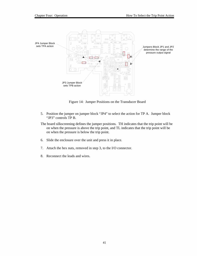
Figure 14: Jumper Positions on the Transducer Board ...............................................................41
Figure 15: Flow Range Selection................................................................................................57

List of Figures
viii
List of Tables
ix
List of Tables
Table 1: Definition of Symbols Found on the Unit ........................................................................ 2
Table 2: I/O Connector Pinout...................................................................................................... 18
Table 3: Initial Configuration ....................................................................................................... 22
Table 4: Highest Pressure for Zero Adjustment of the Pressure Transducer ................................ 36
Table 5: Valve Orifice Size........................................................................................................... 55
Table 6: Valve Orifice Index Number .......................................................................................... 56

List of Tables
x
Safety Information
1
Safety Information
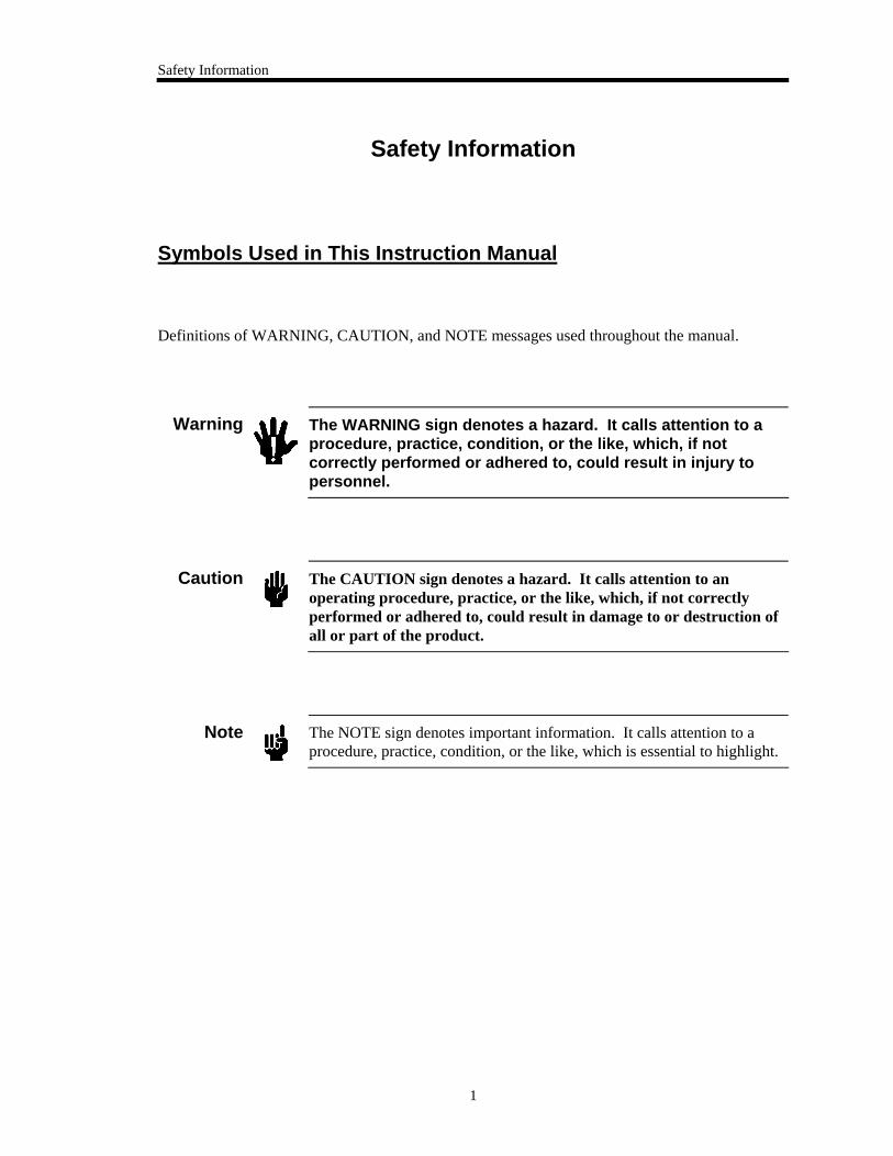
Symbols Used in This Instruction Manual
Definitions of WARNING, CAUTION, and NOTE messages used throughout the manual.
Warning
The WARNING sign denotes a hazard. It calls attention to a procedure, practice, condition, or the like, which, if not correctly performed or adhered to, could result in injury to personnel.
Caution
The CAUTION sign denotes a hazard. It calls attention to an operating procedure, practice, or the like, which, if not correctly performed or adhered to, could result in damage to or destruction of all or part of the product.
Note
The NOTE sign denotes important information. It calls attention to a procedure, practice, condition, or the like, which is essential to highlight.
Safety Information
2
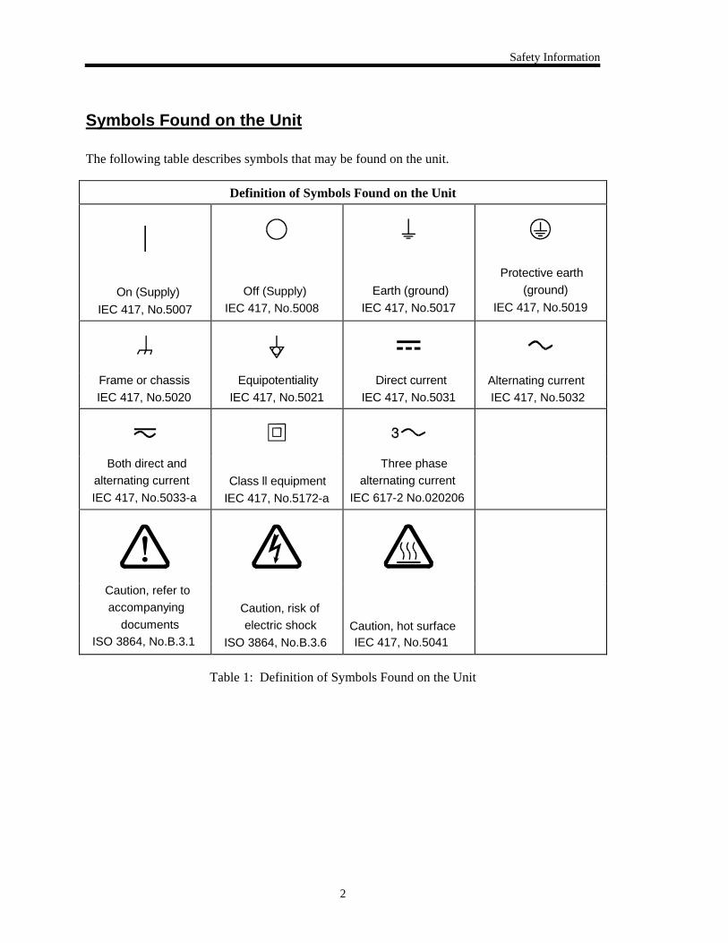
Symbols Found on the Unit
The following table describes symbols that may be found on the unit.
Definition of Symbols Found on the Unit
|
On (Supply) IEC 417, No.5007
Off (Supply)IEC 417, No.5008
Earth (ground) IEC 417, No.5017
Protective earth (ground)
IEC 417, No.5019
Frame or chassis IEC 417, No.5020
Equipotentiality IEC 417, No.5021
Direct current IEC 417, No.5031
Alternating currentIEC 417, No.5032
Both direct andalternating currentIEC 417, No.5033-a
Class ll equipment IEC 417, No.5172-a
Three phasealternating current
IEC 617-2 No.020206
Caution, refer toaccompanying
documentsISO 3864, No.B.3.1
Caution, risk ofelectric shock
ISO 3864, No.B.3.6 Caution, hot surfaceIEC 417, No.5041
Table 1: Definition of Symbols Found on the Unit
Safety Information
3
DO NOT SUBSTITUTE PARTS OR MODIFY INSTRUMENT
Do not install substitute parts or perform any unauthorized modification to the instrument. Return the instrument to an MKS Calibration and Service Center for service and repair to ensure that all safety features are maintained.
SERVICE BY QUALIFIED PERSONNEL ONLY
Operating personnel must not remove instrument covers. Component replacement and internal adjustments must be made by qualified service personnel only.
KEEP AWAY FROM LIVE CIRCUITS
Do not replace components with power cable connected. Under certain conditions, dangerous voltages may exist even with the power cable removed. To avoid injuries, always disconnect power and discharge circuits before touching them.
USE CAUTION WHEN OPERATING WITH HAZARDOUS MATERIALS
If hazardous materials are used, users must take responsibility to observe the proper safety precautions, completely purge the instrument when necessary, and ensure that the material used is compatible with sealing materials.
PURGE THE INSTRUMENT
After installing the unit, or before its removal from a system, be sure to purge the unit completely with a clean dry gas to eliminate all traces of the previously used flow material.
USE PROPER PROCEDURES WHEN PURGING
This instrument must be purged under a ventilation hood, and gloves must be worn to protect personnel.
DO NOT OPERATE IN AN EXPLOSIVE ENVIRONMENT
To avoid explosion, do not operate this product in an explosive environment unless it has been specifically certified for such operation.
Safety Information
4
USE PROPER FITTINGS AND TIGHTENING PROCEDURES
All instrument fittings must be consistent with instrument specifications, and compatible with the intended use of the instrument. Assemble and tighten fittings according to manufacturer's directions.
CHECK FOR LEAK-TIGHT FITTINGS
Before proceeding to instrument setup, carefully check all plumbing connections to the instrument to ensure leak-tight installation.
OPERATE AT SAFE INLET PRESSURES
This unit should never be operated at pressures higher than the rated maximum pressure (refer to the product specifications for the maximum allowable pressure).
INSTALL A SUITABLE BURST DISC
When operating from a pressurized gas source, a suitable burst disc should be installed in the vacuum system to prevent system explosion should the system pressure rise.
KEEP THE UNIT FREE OF CONTAMINANTS
Do not allow contaminants of any kind to enter the unit before or during use. Contamination such as dust, dirt, lint, glass chips, and metal chips may permanently damage the unit.
Chapter One: General Information Introduction
5
Chapter One: General Information
Introduction
The MKS Type 649A Pressure Controller with an Integral Mass Flow Meter combines pressure control and flow metering capabilities into one compact unit. The 649 pressure controller includes a Baratron® capacitance manometer, proportioning control valve, closed-loop electronics, and patented thermal mass flow sensor. The closed-loop control circuitry enables the unit to function as a proportional-integral (PI) controller. The combination of a pressure controller and mass flow meter in one unit makes the 649 pressure controller the ideal solution for backside wafer cooling applications. In addition, the unit’s compact size and small footprint reduce space requirements compared to multi-component systems.
The 649 pressure controller is available with full scale pressure ranges from 1333 Pa to 13.3 kPa and full scale flow rates from 10 to 5000 sccm (nitrogen equivalent). The 649 unit is metal sealed; the valve plug material can be metal, Viton®, Kel-F®, or Kalrez®. The unit can have either Cajon® 4-VCR® male (or equivalent) or 8-VCR male (or equivalent) male fittings.
One Type “D” connector, located on the top of the unit, accepts the input power and has both the pressure (input and output) and flow (output) signals. You can connect the 649 controller to an MKS Type 247 or 246 Mass Flow Controller Power Supply/Readout or a Type 647 Mass Flow and Pressure Programmer/Display unit.
The 649 pressure controller provides two user-settable alarm trip points. The pressure trip points can be set from 1 to 100% of full scale. Each trip point controls an open collector transistor. An LED light located on the top of the unit, indicates the trip point status.
Caution
The control valve within the 649 unit is not a positive shutoff valve. You may need to install a separate positive shutoff valve in your system.
Design Features of the Integral Mass Flow Meter The design of the integral mass flow meter incorporates an advanced flow sensor (U.S. Patent1; Foreign Patents Pending) and an optimized bypass. The latest generation two-element sensing circuit provides accurate, repeatable performance even in low flow ranges (< 10 sccm). Low temperature effect from ambient temperature change and a low attitude sensitivity effect are also ensured. The newly optimized sensor/bypass arrangement minimizes the flow splitting error for gases with different densities, which dramatically improves measurement accuracy when gases other than the calibration gas are used.
1 U.S. Patent 5461913; foreign patents pending.
How This Manual is Organized Chapter One: General Information
6
Cleanliness Features The design of the pressure controller ensures extremely low external leakage and minimizes a key source of particle generation, outgassing, and permeation. The design also incorporates minimal wetted surface area. To further ensure its cleanliness, the 649 controller undergoes precision machining as well as a proprietary cleaning process. The instrument is assembled and double-bagged in a Class 100 clean room.
How This Manual is Organized
This manual is designed to provide instructions on how to set up, install, and operate a Type 649 unit.
Before installing your Type 649 unit in a system and/or operating it, carefully read and familiarize yourself with all precautionary notes in the Safety Messages and Procedures section at the front of this manual. In addition, observe and obey all WARNING and CAUTION notes provided throughout the manual.
Chapter One, General Information, (this chapter) introduces the product and describes the organization of the manual.
Chapter Two, Installation, explains the environmental requirements and describes how to mount the instrument in your system.
Chapter Three, Overview, gives a brief description of the instrument and its functionality.
Chapter Four, Operation, describes how to use the instrument and explains all the functions and features.
Chapter Five, Maintenance, lists any maintenance required to keep the instrument in good working condition.
Chapter Six, Troubleshooting, provides a reference should the instrument malfunction.
Appendix A: Product Specifications, lists the specifications of the instrument.
Appendix B: Model Code Explanation, describes the model code.
Appendix C: Valve Orifice Selection, presents the information used to select the appropriate flow range for nitrogen and other gases.
Appendix D: Gas Correction Factors, lists the gas correction factors of commonly used gases.
Manual Conventions The following conventions apply throughout this manual:
XXXXXX For inputs: Indicates that the line must be pulled low to activate the function.
XXXXXX For outputs: Indicates that the output is active low.
Chapter One: General Information Customer Support
7
Customer Support
Standard maintenance and repair services are available through all of our regional MKS Calibration and Service Centers, listed on the back cover. In addition, MKS accepts the instruments of other manufacturers for recalibration using the Primary and Transfer Standard calibration equipment located at all of our regional service centers. Should any difficulties arise in the use of your Type 649 instrument, or to obtain information about companion products MKS offers, contact any authorized MKS Calibration and Service Center. If it is necessary to return the instrument to MKS, please obtain an ERA Number (Equipment Return Authorization Number) from the MKS Calibration and Service Center before shipping. The ERA Number expedites handling and ensures proper servicing of your instrument.
Please refer to the inside of the back cover of this manual for a list of MKS Calibration and Service Centers.
Warning
All returns to MKS Instruments must be free of harmful, corrosive, radioactive, or toxic materials.

Customer Support Chapter One: General Information
8
This page intentionally left blank.
Chapter Two: Installation How To Unpack the Type 649 Unit
9
Chapter Two: Installation
How To Unpack the Type 649 Unit
MKS has carefully packed the Type 649 unit so that it will reach you in perfect operating order. Upon receiving the unit, however, you should check for defects, cracks, broken connectors, etc., to be certain that damage has not occurred during shipment.
Note
Do not discard any packing materials until you have completed your inspection and are sure the unit arrived safely.
If you find any damage, notify your carrier and MKS immediately. If it is necessary to return the unit to MKS, obtain an ERA Number (Equipment Return Authorization Number) from the MKS Service Center before shipping. Please refer to the inside of the back cover of this manual for a list of MKS Calibration and Service Centers.
Opening the Package The 649 controller is assembled, leak tested with helium, and calibrated in a clean room environment. The instrument is double-bagged in this environment to ensure maintenance of its particle free condition during shipment. It is very important to remove the bags according to clean room practices. To maintain at least a minimal level of clean room standards, follow the instructions below.
1. Remove the outer bag in an ante room (garmenting room) or transfer box.
Do not allow this outer bag to enter the clean room.
2. Remove the inner bag in the clean room.
Caution
Only qualified individuals should perform the installation and any user adjustments. They must comply with all the necessary ESD and handling precautions while installing and adjusting the instrument. Proper handling is essential when working with all highly sensitive precision electronic instruments.
How To Unpack the Type 649 Unit Chapter Two: Installation
10
Unpacking Checklist
Standard Equipment:
• Type 649 Unit
• Type 649 Instruction Manual (this book)
Optional Equipment:
• Electrical Connector Accessories Kit - 649A-K1
• Interface cables (refer to Interface Cables, page 11)
Chapter Two: Installation Interface Cables
11
Interface Cables
Use a CB649S-1-xx or CB649-1-xx cable (where xx indicates the length) to connect the 649 controller to an MKS Type 247 or 246 Mass Flow Controller Power Supply/Readout or a Type 647 Mass Flow and Pressure Programmer/Display unit. The standard cable, CB649-1-10, is 10 feet in length.
Note
To order a metal braided shielded cable, add an “S” after the cable type designation. For example, for an overall metal braided shielded cable order CB649S-1 for; order CB649-1 for a non-shielded cable.
Generic Shielded Cable Description
Should you choose to manufacture your own cables, follow the guidelines listed below:
1. The cable must have an overall metal braided shield, covering all wires. Neither aluminum foil nor spiral shielding will be as effective; using either may nullify regulatory compliance.
2. The connectors must have a metal case which has direct contact to the cable’s shield on the whole circumference of the cable. The inductance of a flying lead or wire from the shield to the connector will seriously degrade the shield’s effectiveness. The shield should be grounded to the connector before its internal wires exit.
3. With very few exceptions, the connector(s) must make good contact to the device’s case (ground). “Good contact” is about 0.01 ohms; and the ground should surround all wires. Contact to ground at just one point may not suffice.
4. For shielded cables with flying leads at one or both ends; it is important at each such end, to ground the shield before the wires exit. Make this ground with absolute minimum length. (A 6.35 mm piece of #22 wire may be undesirably long since it has approximately 5 nH of inductance, equivalent to 31 ohms at 1000 MHz). After picking up the braid’s ground, keep wires and braid flat against the case. With very few exceptions, grounded metal covers are not required over terminal strips. If one is required, it will be stated in the Declaration of Conformity or in the instruction manual.
5. In selecting the appropriate type and wire size for cables, consider:
A. The voltage ratings;
B. The cumulative I2R heating of all the conductors (keep them safely cool);
C. The IR drop of the conductors, so that adequate power or signal voltage gets to the device;
D. The capacitance and inductance of cables which are handling fast signals, (such as data lines or stepper motor drive cables); and
E. That some cables may need internal shielding from specific wires to others; please see the instruction manual for details regarding this matter.
Product Location and Requirements Chapter Two: Installation
12
Product Location and Requirements
• Ventilation requirements include sufficient air circulation
• Maintain the normal operating temperature between 0° and 50° C
• Maximum differential pressure is 1034 kPa, consistent with the overpressure limit of the pressure transducer
Refer to Applications with a Large Differential Pressure, page 33, for more information.
• Pressure transducer overpressure limit: 310 kPa or 2 times full scale, whichever is greater
• Provide power input at ±15 VDC (±5%) @ 250 mA
1. Maximum voltage/current at startup is ±15 VDC (±5%) @ 250 mA
2. Typical steady state voltage/current should be ±15 VDC (±5%) @ 200 mA
• Warm up time: 5 minutes
• Use high purity gas and filters in line upstream of the controller
• Mount the 649 controller in an upright position if possible, although any mounting orientation is satisfactory
Refer to Installing the Unit, page 17, for more information.
• Install a separate positive shutoff valve if your system cannot tolerate some leakage across the control valve in the 649 controller
The control valve is not a positive shutoff valve so some leakage across the valve may occur.
Warning
Follow your corporate policy for handling toxic or hazardous gases. Your corporate policy on handling these gases supersedes the instructions in this manual. MKS assumes no liability for the safe handling of such materials.
• Install the 649 controller in a “flowing” system where gas is continually added and evacuated
Do not use the controller in a “dead-ended” system (a system which cannot remove excess pressure). The 649 controller is not designed to vent excess pressure to the atmosphere.
Chapter Two: Installation Dimensions
13
• Verify that your pressure system can withstand pressure equal to the full scale range of the pressure transducer
Your pressure system may be exposed to the full scale pressure since the 649 controller will control over the entire full scale range of the pressure transducer. As a precaution, you may choose to install a safety valve in your system to vent excess pressure.
Dimensions
Note
All dimensions are listed in inches with millimeters referenced in parentheses.
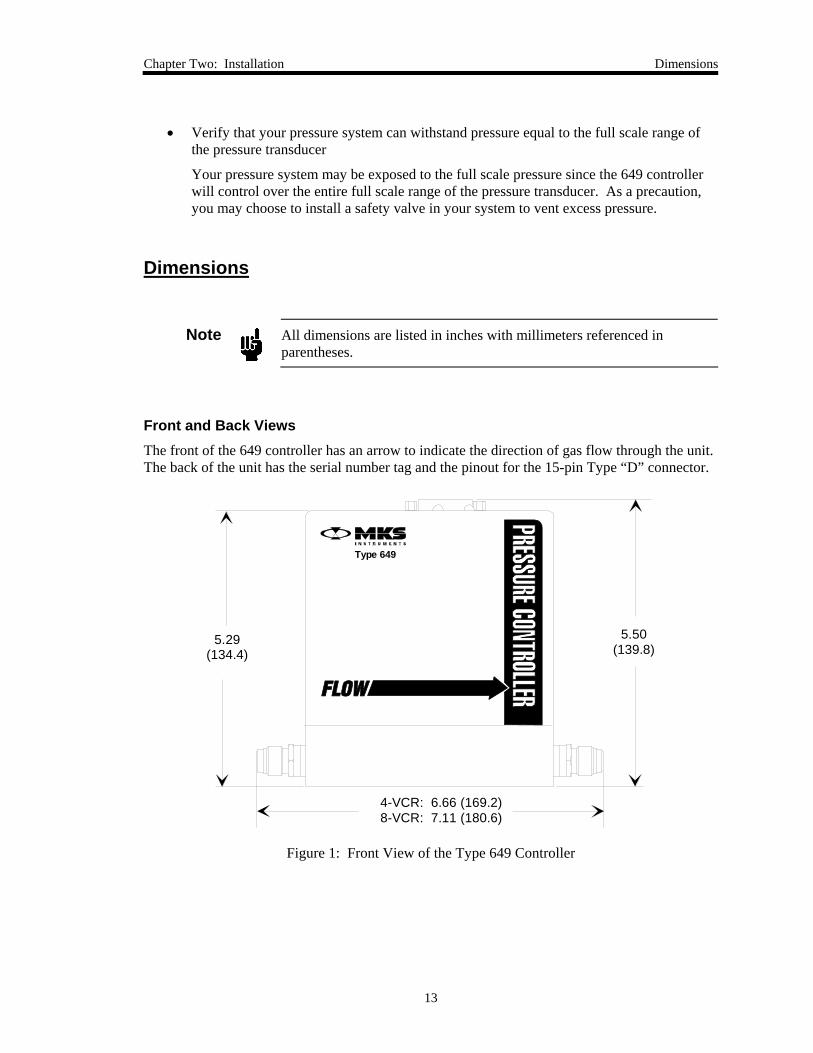
Front and Back Views The front of the 649 controller has an arrow to indicate the direction of gas flow through the unit. The back of the unit has the serial number tag and the pinout for the 15-pin Type “D” connector.
5.29(134.4)
5.50(139.8)
4-VCR: 6.66 (169.2)8-VCR: 7.11 (180.6)
Type 649
Figure 1: Front View of the Type 649 Controller
Dimensions Chapter Two: Installation
14
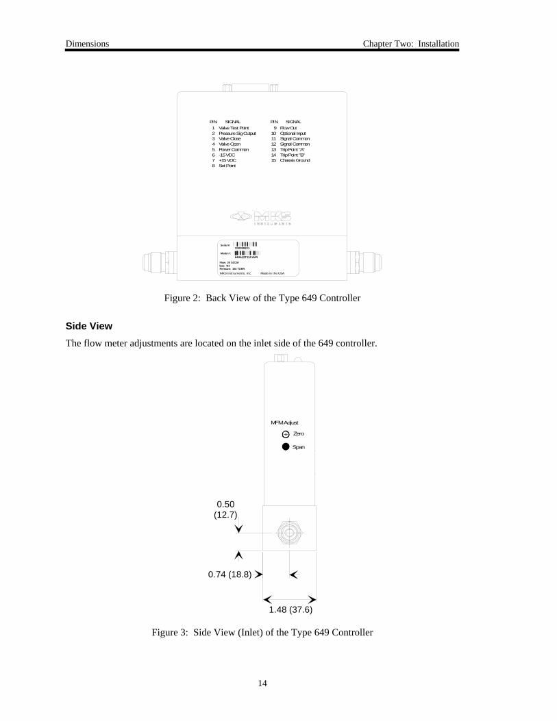
PIN1 2 3 4 5 6 7 8
Valve Test Point Pressure Sig Output Valve Close Valve Open Power Common -15 VDC +15 VDC Set Point
SIGNAL SIGNALFlow Out Optional Input Signal Common Signal Common Trip Point "A" Trip Point "B" Chassis Ground
9 10 11 12 13 14 15
PIN
649A12T21CAVR
Serial #:
Model #:
000098221
MKS Instruments, Inc. Made in the USA
Flow: 20 SCCMGas: N2Pressure: 100 TORR
Figure 2: Back View of the Type 649 Controller
Side View The flow meter adjustments are located on the inlet side of the 649 controller.
0.50(12.7)
0.74 (18.8)
1.48 (37.6)
MFM Adjust
Span
Zero
Figure 3: Side View (Inlet) of the Type 649 Controller
Chapter Two: Installation Dimensions
15
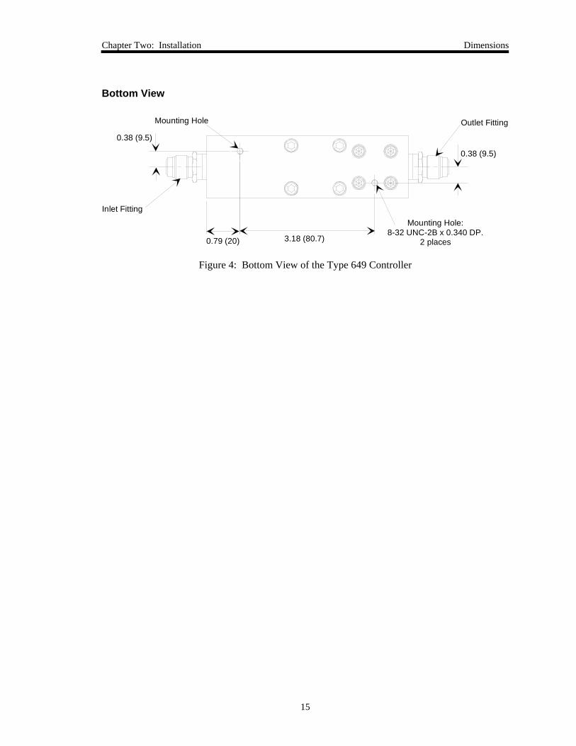
Bottom View
0.38 (9.5)
0.79 (20) 3.18 (80.7)
0.38 (9.5)
Mounting Hole: 8-32 UNC-2B x 0.340 DP.
2 places
Mounting Hole
Inlet Fitting
Outlet Fitting
Figure 4: Bottom View of the Type 649 Controller
Setup Chapter Two: Installation
16
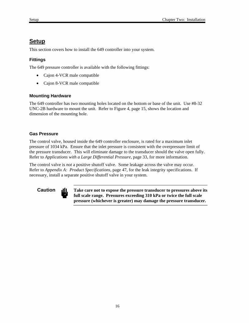
Setup This section covers how to install the 649 controller into your system.
Fittings The 649 pressure controller is available with the following fittings:
• Cajon 4-VCR male compatible
• Cajon 8-VCR male compatible
Mounting Hardware The 649 controller has two mounting holes located on the bottom or base of the unit. Use #8-32 UNC-2B hardware to mount the unit. Refer to Figure 4, page 15, shows the location and dimension of the mounting hole.
Gas Pressure The control valve, housed inside the 649 controller enclosure, is rated for a maximum inlet pressure of 1034 kPa. Ensure that the inlet pressure is consistent with the overpressure limit of the pressure transducer. This will eliminate damage to the transducer should the valve open fully. Refer to Applications with a Large Differential Pressure, page 33, for more information.
The control valve is not a positive shutoff valve. Some leakage across the valve may occur. Refer to Appendix A: Product Specifications, page 47, for the leak integrity specifications. If necessary, install a separate positive shutoff valve in your system.
Caution
Take care not to expose the pressure transducer to pressures above its full scale range. Pressures exceeding 310 kPa or twice the full scale pressure (whichever is greater) may damage the pressure transducer.
Chapter Two: Installation Setup
17
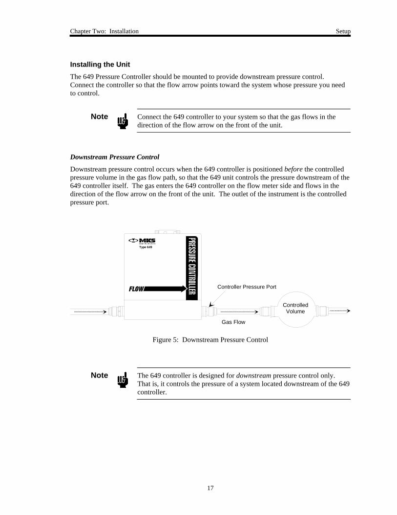
Installing the Unit The 649 Pressure Controller should be mounted to provide downstream pressure control. Connect the controller so that the flow arrow points toward the system whose pressure you need to control.
Note
Connect the 649 controller to your system so that the gas flows in the direction of the flow arrow on the front of the unit.
Downstream Pressure Control
Downstream pressure control occurs when the 649 controller is positioned before the controlled pressure volume in the gas flow path, so that the 649 unit controls the pressure downstream of the 649 controller itself. The gas enters the 649 controller on the flow meter side and flows in the direction of the flow arrow on the front of the unit. The outlet of the instrument is the controlled pressure port.
Gas Flow
ControlledVolume
Controller Pressure Port
Type 649
Figure 5: Downstream Pressure Control
Note
The 649 controller is designed for downstream pressure control only. That is, it controls the pressure of a system located downstream of the 649 controller.
Electrical Information Chapter Two: Installation
18
Electrical Information
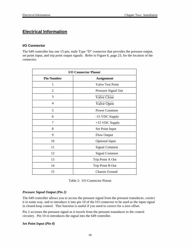
I/O Connector The 649 controller has one 15-pin, male Type “D” connector that provides the pressure output, set point input, and trip point output signals. Refer to Figure 6, page 23, for the location of the connector.
I/O Connector Pinout
Pin Number Assignment
1 Valve Test Point
2 Pressure Signal Out
3 Valve Close
4 Valve Open
5 Power Common
6 -15 VDC Supply
7 +15 VDC Supply
8 Set Point Input
9 Flow Output
10 Optional Input
11 Signal Common
12 Signal Common
13 Trip Point A Out
14 Trip Point B Out
15 Chassis Ground
Table 2: I/O Connector Pinout
Pressure Signal Output (Pin 2)
The 649 controller allows you to access the pressure signal from the pressure transducer, correct it in some way, and re-introduce it into pin 10 of the I/O connector to be used as the input signal in closed-loop control. This function is useful if you need to correct for a zero offset.
Pin 2 accesses the pressure signal as it travels from the pressure transducer to the control circuitry. Pin 10 re-introduces the signal into the 649 controller.
Set Point Input (Pin 8)
Chapter Two: Installation Electrical Information
19
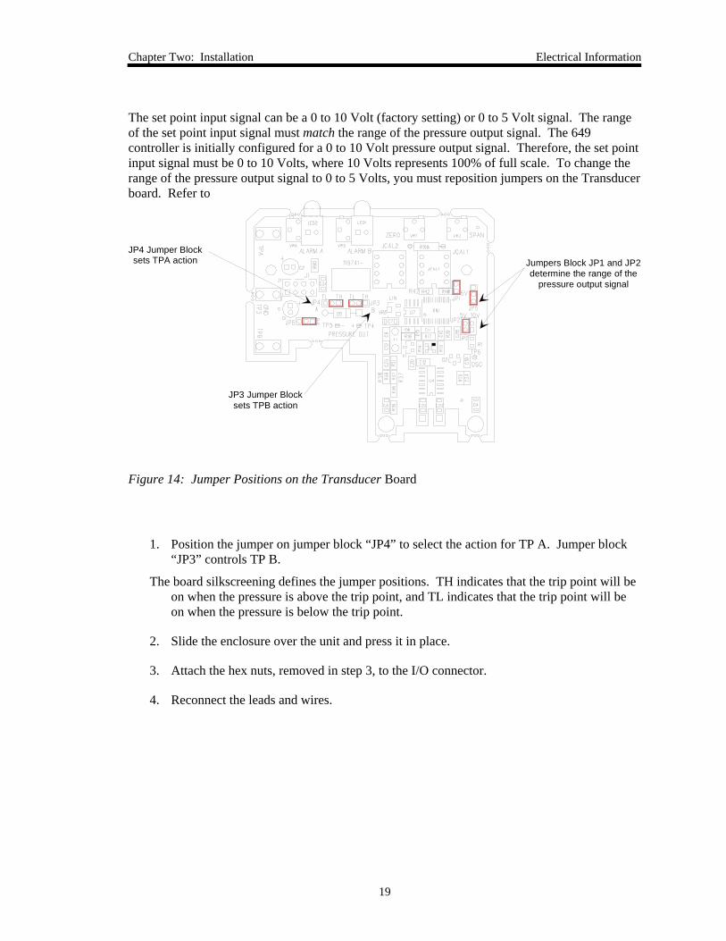
The set point input signal can be a 0 to 10 Volt (factory setting) or 0 to 5 Volt signal. The range of the set point input signal must match the range of the pressure output signal. The 649 controller is initially configured for a 0 to 10 Volt pressure output signal. Therefore, the set point input signal must be 0 to 10 Volts, where 10 Volts represents 100% of full scale. To change the range of the pressure output signal to 0 to 5 Volts, you must reposition jumpers on the Transducer board. Refer to
JP4 Jumper Blocksets TPA action
JP3 Jumper Blocksets TPB action
Jumpers Block JP1 and JP2determine the range of the
pressure output signal
Figure 14: Jumper Positions on the Transducer Board
1. Position the jumper on jumper block “JP4” to select the action for TP A. Jumper block “JP3” controls TP B.
The board silkscreening defines the jumper positions. TH indicates that the trip point will be on when the pressure is above the trip point, and TL indicates that the trip point will be on when the pressure is below the trip point.
2. Slide the enclosure over the unit and press it in place.
3. Attach the hex nuts, removed in step 3, to the I/O connector.
4. Reconnect the leads and wires.
How To Use Trip Points as Error Indicators Chapter Two: Installation
20
How To Use Trip Points as Error Indicators
You can use the trip points to indicate when the error signal deviates from a given range. The error is defined as the difference between the actual pressure reading and the set point.
For example, assume you have a 13.33 kPa unit and your set point is 6.666 kPa. You want the trip points to illuminate when the error is more than ±5% of the set point value, which indicates that the pressure reading has deviated by more than ±0.333 kPa. This allows the pressure to vary from 6.333 to 6.999 kPa.
The 649 controller is initially configured with TP A on above the trip point and TP B on below the trip point. If you have not changed the action of either trip point, you may follow the steps below. If you have changed the action of the trip points, you need to reset them back to the initial configuration for this example. Refer to How To Adjust the Trip Point Values, page 37, for instructions.
1. Calculate the trip point voltage that corresponds to each trip point value:
Trip Point Pressure (Torr)Full Scale Pressure (Torr)
x TP Adjustment Range (V) = Trip Point Voltage (V)
where the full scale pressure is 13.33 kPa and the TP adjustment range is 5 Volts.
TP A: 6.999 kPa13.33 kPa
5 V 2.625 Volts× =
TP B: 6.333 kPa13.33 kPa
5 V Volts× = 2 375.
2. Measure the value of TP A by inserting a positive test probe into the test jack labeled “TP A” and the ground probe into the test jack labeled “Gnd.”
The ground connection and the test jacks are located inside the unit on the Transducer board, as shown Figure 14, page 39. A 0 to 5 V signal corresponds to a 0 to 100% full scale pressure.
3. Use a small screwdriver to adjust the pot for TP A, located on the top of the unit, to set TP A to 2.625 Volts.
Refer to Figure 6, page 21, for the location of the trip point adjustments.
4. Measure the value of TP B by inserting a positive test probe into the test jack labeled “TP B” and the ground probe into the test jack labeled “Gnd.”
5. Use a small screwdriver to adjust the pot for TP B, to set TP B to 2.375 Volts.
The trip points will be off when the pressure reading is between 6.333 to 6.999 kPa. Should the pressure deviate from this range the appropriate trip point will turn on and its LED will illuminate. Trip Point A will turn on when the pressure exceeds 6.999 kPa and Trip Point B will turn on when the pressure falls below 6.333 kPa.
Chapter Two: Installation How To Use Trip Points as Error Indicators
21
How To Change the Pressure Output Signal Range, page 41, for instructions on changing the pressure output range.
Note
The 649 controller must have sufficient pressure on its inlet side to achieve the set point.
Flow Output Signal (Pin 9)
The flow output signal is available on pin 9. You can introduce this signal into another system to monitor the flow rate. The flow output signal is 0 to 5 Volts, which is standard for most thermal mass flow meters.
Optional Input (Pin 10)
Use pin 10 to re-introduce another signal, such as a zero corrected pressure signal, into the control circuitry of the 649 controller. When a signal on pin 10 is introduced, the controlled voltage, which goes to the control loop is the mid-value between the Pressure Output signal (pin 2) and the signal at pin 10.
The Trip Point Outputs (Pins 13 and 14)
The 649 controller offers two alarm trip points: Trip Point A and Trip Point B. Each trip point has an LED and adjustment pot on the top cover. The trip points are open collector transistors.
The trip points can be set from 1 to 100% of full scale by adjusting the appropriate trip point pot located on the top of the unit. The trip point setting is a 0 to 5 VDC signal available inside of the unit.
Use the appropriate trip point output signal to control a relay or another piece of equipment, such as a valve, or as a digital input to a computer. The trip point signal is pulled to ground when the trip point is on. The voltage value of the pin is 5 Volts when the respective trip point is off.
Refer to Trip Points, page 32, for a complete description of the trip points.
Initial Configuration Chapter Two: Installation
22
Initial Configuration
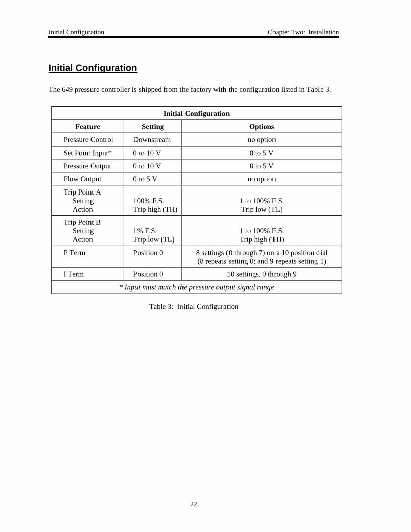
The 649 pressure controller is shipped from the factory with the configuration listed in Table 3.
Initial Configuration
Feature Setting Options
Pressure Control Downstream no option
Set Point Input* 0 to 10 V 0 to 5 V
Pressure Output 0 to 10 V 0 to 5 V
Flow Output 0 to 5 V no option
Trip Point A Setting Action
100% F.S. Trip high (TH)
1 to 100% F.S. Trip low (TL)
Trip Point B Setting Action
1% F.S. Trip low (TL)
1 to 100% F.S. Trip high (TH)
P Term Position 0 8 settings (0 through 7) on a 10 position dial (8 repeats setting 0; and 9 repeats setting 1)
I Term Position 0 10 settings, 0 through 9
* Input must match the pressure output signal range
Table 3: Initial Configuration
Chapter Three: Overview General Information
23
Chapter Three: Overview
General Information
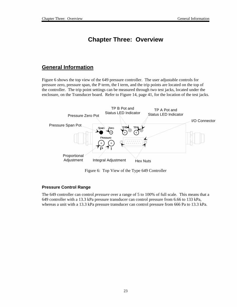
Figure 6 shows the top view of the 649 pressure controller. The user adjustable controls for pressure zero, pressure span, the P term, the I term, and the trip points are located on the top of the controller. The trip point settings can be measured through two test jacks, located under the enclosure, on the Transducer board. Refer to Figure 14, page 41, for the location of the test jacks.
Zero TPB TPASpan
IP
Pressure
I/O Connector
TP A Pot and Status LED Indicator
TP B Pot and Status LED Indicator
Pressure Zero Pot
Pressure Span Pot
ProportionalAdjustment Integral Adjustment Hex Nuts
Figure 6: Top View of the Type 649 Controller
Pressure Control Range The 649 controller can control pressure over a range of 5 to 100% of full scale. This means that a 649 controller with a 13.3 kPa pressure transducer can control pressure from 6.66 to 133 kPa, whereas a unit with a 13.3 kPa pressure transducer can control pressure from 666 Pa to 13.3 kPa.
General Information Chapter Three: Overview
24
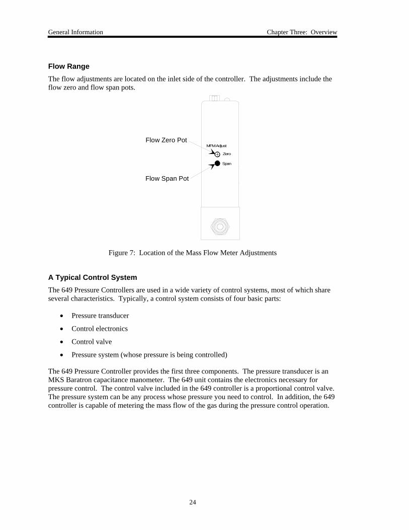
Flow Range The flow adjustments are located on the inlet side of the controller. The adjustments include the flow zero and flow span pots.
MFM Adjust
Span
Zero
Flow Zero Pot
Flow Span Pot
Figure 7: Location of the Mass Flow Meter Adjustments
A Typical Control System The 649 Pressure Controllers are used in a wide variety of control systems, most of which share several characteristics. Typically, a control system consists of four basic parts:
• Pressure transducer
• Control electronics
• Control valve
• Pressure system (whose pressure is being controlled)
The 649 Pressure Controller provides the first three components. The pressure transducer is an MKS Baratron capacitance manometer. The 649 unit contains the electronics necessary for pressure control. The control valve included in the 649 controller is a proportional control valve. The pressure system can be any process whose pressure you need to control. In addition, the 649 controller is capable of metering the mass flow of the gas during the pressure control operation.
Chapter Three: Overview How The 649 Pressure Controller Works
25
How The 649 Pressure Controller Works
The 649 controller compares the pressure reading to the set point, and positions the valve to maintain, or achieve, the set point pressure. The controller functions as a PI (Proportional-Integral) controller. Both the Proportional (P) term, and the Integral (I) term have adjustable dials on the top of the 649 controller.
Downstream pressure control is defined as having the process chamber located downstream of the 649 controller. Therefore, the 649 controller controls the pressure of the process chamber located downstream.
Example
Assume that your 649 controller is positioned for downstream control. The 649 controller is positioned before the controlled pressure volume so it will regulate the pressure of the gas entering the pressure system. Figure 5, page 17, shows the correct location for the 649 controller.
When the actual pressure reading is less than the set point value, the 649 controller opens the valve to increase the amount of gas entering the system. As the valve opens, gas enters the pressure system, so the pressure rises to meet the set point value.
When the actual pressure reading is greater than the set point value, the 649 controller closes the valve to decrease the amount of gas entering the system. As the valve closes, less gas enters the pressure system, so the pressure drops to meet the set point value.
Flow Measurement Overview Chapter Three: Overview
26
Flow Measurement Overview
The 649 controller measures the mass flow rate of a gas.
Flow Path Upon entering the 649 controller, the gas stream passes first through the metering section of the instrument for its mass flow to be measured. The gas moves on through the control valve, which regulates the pressure according to the given set point, and then exits the instrument at the established pressure.
The metering section consists of one of the following:
• A sensor tube for ranges < 10 sccm (N2 equivalent)
• A sensor tube and parallel bypass for ranges > 10 sccm (N2 equivalent)
The geometry of the sensor tube, in conjunction with the specified full scale flow rate, ensures fully developed laminar flow in the sensing region. The bypass elements, in those instruments containing them, are specifically matched to the characteristics of the sensor tube to achieve a laminar flow splitting ratio which remains constant throughout each range.
Measurement Technique The flow measurement is based on differential heat transfer between temperature sensing heater elements which are attached symmetrically to the sensor tube. This senses the thermal mass movement which is converted to mass flow via the specific heat, Cp, of the gas. The resulting signal is amplified to provide a 0 to 5 VDC output which is proportional to mass flow.
Chapter Three: Overview Tuning the 649 Pressure Controller
27
Tuning the 649 Pressure Controller
Tuning optimizes the way the 649 unit controls your system. The Proportional (P) and Integral (I) terms adjust the response of the 649 controller. The controller responds to changes in either the pressure of the system or the value of the set point.
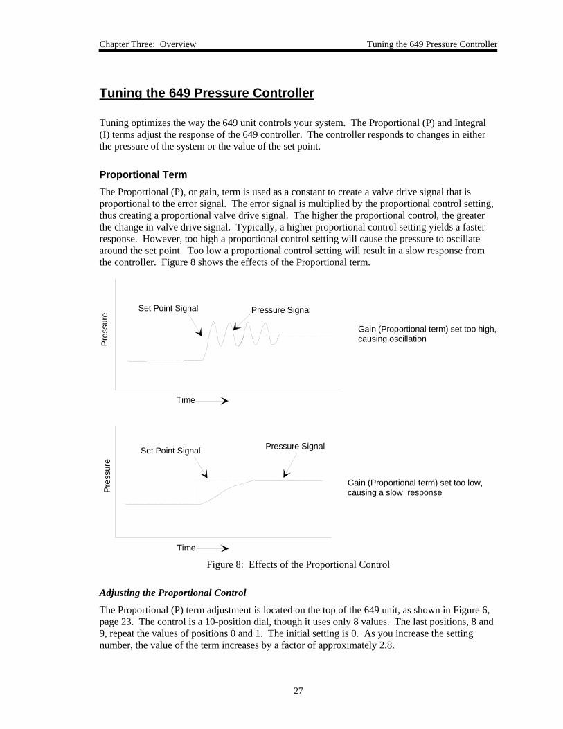
Proportional Term The Proportional (P), or gain, term is used as a constant to create a valve drive signal that is proportional to the error signal. The error signal is multiplied by the proportional control setting, thus creating a proportional valve drive signal. The higher the proportional control, the greater the change in valve drive signal. Typically, a higher proportional control setting yields a faster response. However, too high a proportional control setting will cause the pressure to oscillate around the set point. Too low a proportional control setting will result in a slow response from the controller. Figure 8 shows the effects of the Proportional term.
Set Point Signal Pressure Signal
Time
Pres
sure
Gain (Proportional term) set too low,causing a slow response
Pressure SignalSet Point Signal
Time
Pre
ssur
e
Gain (Proportional term) set too high,causing oscillation
Figure 8: Effects of the Proportional Control
Adjusting the Proportional Control
The Proportional (P) term adjustment is located on the top of the 649 unit, as shown in Figure 6, page 23. The control is a 10-position dial, though it uses only 8 values. The last positions, 8 and 9, repeat the values of positions 0 and 1. The initial setting is 0. As you increase the setting number, the value of the term increases by a factor of approximately 2.8.
Tuning the 649 Pressure Controller Chapter Three: Overview
28
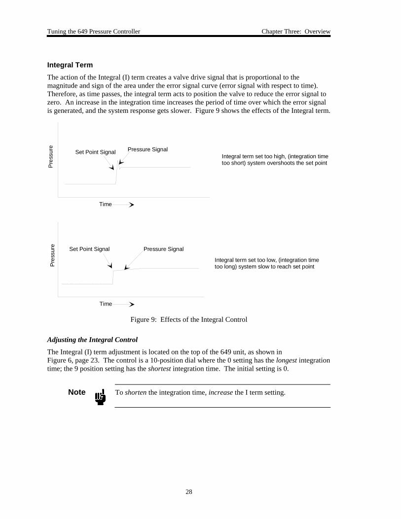
Integral Term The action of the Integral (I) term creates a valve drive signal that is proportional to the magnitude and sign of the area under the error signal curve (error signal with respect to time). Therefore, as time passes, the integral term acts to position the valve to reduce the error signal to zero. An increase in the integration time increases the period of time over which the error signal is generated, and the system response gets slower. Figure 9 shows the effects of the Integral term.
Set Point Signal Pressure Signal
Time
Pre
ssur
e
Integral term set too low, (integration timetoo long) system slow to reach set point
Pressure SignalSet Point Signal
Time
Pre
ssur
e
Integral term set too high, (integration time too short) system overshoots the set point
Figure 9: Effects of the Integral Control
Adjusting the Integral Control
The Integral (I) term adjustment is located on the top of the 649 unit, as shown in Figure 6, page 23. The control is a 10-position dial where the 0 setting has the longest integration time; the 9 position setting has the shortest integration time. The initial setting is 0.
Note
To shorten the integration time, increase the I term setting.
Chapter Three: Overview Tuning the 649 Pressure Controller
29
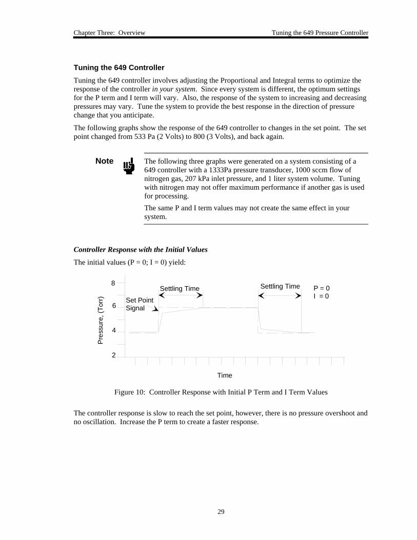
Tuning the 649 Controller Tuning the 649 controller involves adjusting the Proportional and Integral terms to optimize the response of the controller in your system. Since every system is different, the optimum settings for the P term and I term will vary. Also, the response of the system to increasing and decreasing pressures may vary. Tune the system to provide the best response in the direction of pressure change that you anticipate.
The following graphs show the response of the 649 controller to changes in the set point. The set point changed from 533 Pa (2 Volts) to 800 (3 Volts), and back again.
Note
The following three graphs were generated on a system consisting of a 649 controller with a 1333Pa pressure transducer, 1000 sccm flow of nitrogen gas, 207 kPa inlet pressure, and 1 liter system volume. Tuning with nitrogen may not offer maximum performance if another gas is used for processing. The same P and I term values may not create the same effect in your system.
Controller Response with the Initial Values
The initial values (P = 0; I = 0) yield:
P = 0I = 0
Settling Time Settling Time
Set PointSignal
4
2
6
8
Pre
ssur
e, (T
orr)
Time
Figure 10: Controller Response with Initial P Term and I Term Values
The controller response is slow to reach the set point, however, there is no pressure overshoot and no oscillation. Increase the P term to create a faster response.
Tuning the 649 Pressure Controller Chapter Three: Overview
30
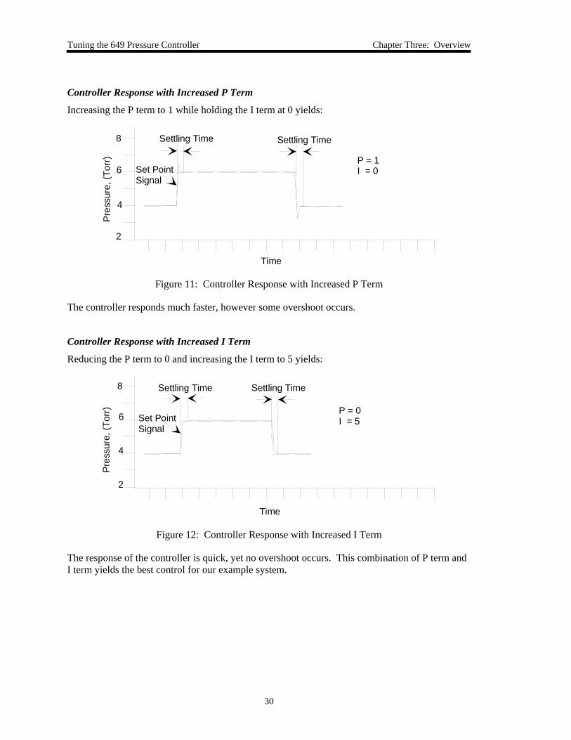
Controller Response with Increased P Term
Increasing the P term to 1 while holding the I term at 0 yields:
P = 1I = 0
Settling Time Settling Time
Set PointSignal
4
2
6
8
Pre
ssur
e, (T
orr)
Time
Figure 11: Controller Response with Increased P Term
The controller responds much faster, however some overshoot occurs.
Controller Response with Increased I Term
Reducing the P term to 0 and increasing the I term to 5 yields:
P = 0I = 5
Settling Time Settling Time
Set PointSignal
4
2
6
8
Pre
ssur
e, (T
orr)
Time
Figure 12: Controller Response with Increased I Term
The response of the controller is quick, yet no overshoot occurs. This combination of P term and I term yields the best control for our example system.
Chapter Three: Overview Priority of Commands
31
Priority of Commands
The 649 controller has an established hierarchy that it uses to determine which commands take precedence. The commands and operating modes are listed according to the order of priority (from highest to lowest):
• Valve Close Command
• Valve Open Command
• Set Point Recognition Operating Mode
• Closed-Loop Control Operating Mode
Valve Close and Valve Open Commands: The valve override commands immediately move the valve to the appropriate position, either closed or open. These valve commands take precedence over any other operation. The overline ( ) indicates that the valve commands are active when their respective pins are pulled low. For example, if the valve is currently operating under pressure control to maintain a desired pressure, and the Valve Open pin (pin 4) is pulled low, the valve will move to the fully open position. The Valve Close command has the highest priority. Therefore, if both the Valve Open and Valve Close commands are issued, the valve will move to the fully closed position.
Set Point Recognition Operating Mode: The 649 controller can control pressure, within its specifications, over the range from 5 to 100% of full scale. Under certain conditions the 649 is capable of controlling below 5% down to 1%, although performance in this control range is application dependent. If the set point signal is less than 1% of full scale, the set point recognition becomes effective. The 649 controller positions its valve in the fully closed position. Increase the set point signal to a value greater than 1% of full scale to resume pressure control.
Closed-Loop Control Operating Mode: When the 649 controller operates in closed-loop control mode, it compares the pressure signal from its transducer (pin 2) or any signal on the Optional Input pin (pin 10) to the set point. The 649 controller positions its valve to achieve or maintain the set point pressure (or other variable if the Optional Input is used) in the system. Closed-loop control mode has the lowest priority. The 649 controller defaults to closed-loop control in the absence of any higher priority commands.
Refer to I/O Connector, page 18, for more information on the Optional Input function.
Trip Points Chapter Three: Overview
32
Trip Points
The 649 controller provides two trip points (Trip Point A and Trip Point B). Each trip point operates independently and controls an open collector output that can be connected to an external relay. Each trip point has an adjustment pot, a status LED, and a test jack. Refer to Figure 6, page 23, for the location of the trip point adjustment pots and LEDs. The test jacks are located inside of the unit, under the enclosure, as shown in Figure 14, page 41. Refer to How To Adjust the Trip Point Values, page 39, for instructions on changing the trip point values.
Action of the Trip Points The trip points can be turned on when the pressure is above or below the trip point value, depending upon the location of jumpers on the Transducer board. The initial configuration is:
• Trip Point A is set to trip high; it is on when the pressure is above the trip point (it is off when the pressure is below the trip point value)
• Trip Point B is set to trip low; it is on when the pressure is below the trip point (it is off when the pressure is above the trip point value)
When on, the trip point is connected, through the collector of an NPN transistor, to power ground. Refer to Trip Point Specifications, page 49, for the ratings. You can use the unit’s trip point output (available on pins 13 and 14 of the I/O connector) for further process control. The complete pinout for the I/O connector is listed in Table 2, page 18.
To change the action of a trip point, refer to How To Select the Trip Point Action, page 40.
Note
The trip points react to the pressure signal only; not the flow signal.
Chapter Three: Overview Applications with a Large Differential Pressure
33
Applications with a Large Differential Pressure
Applications with a large differential pressure between the inlet and outlet, or a large inlet pressure, may require special precautions:
• If the inlet pressure is more than two times the pressure transducer full scale pressure or 310 kPa, whichever is greater
You must ensure that the valve will never be fully opened to the pressure transducer. Pressures in excess of 310 kPa or two times the pressure transducer full scale (whichever is greater) may damage the pressure transducer.
• The inlet pressure on the valve is 1034 kPa
This is the maximum inlet pressure rating of the valve. The force of high inlet pressure on the valve may inhibit valve movement. A normally closed valve may be unable to open.
Labels
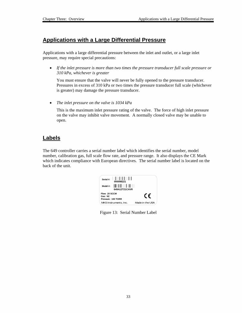
The 649 controller carries a serial number label which identifies the serial number, model number, calibration gas, full scale flow rate, and pressure range. It also displays the CE Mark which indicates compliance with European directives. The serial number label is located on the back of the unit.
649A12T21CAVR
Serial #:
Model #:
000098221
MKS Instruments, Inc. Made in the USA
Flow: 20 SCCMGas: N2Pressure: 100 TORR
Figure 13: Serial Number Label
The Gas Correction Factor (GCF) for Flow Metering Chapter Three: Overview
34
The Gas Correction Factor (GCF) for Flow Metering
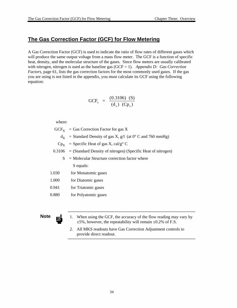
A Gas Correction Factor (GCF) is used to indicate the ratio of flow rates of different gases which will produce the same output voltage from a mass flow meter. The GCF is a function of specific heat, density, and the molecular structure of the gases. Since flow meters are usually calibrated with nitrogen, nitrogen is used as the baseline gas (GCF = 1). Appendix D: Gas Correction Factors, page 61, lists the gas correction factors for the most commonly used gases. If the gas you are using is not listed in the appendix, you must calculate its GCF using the following equation:
GCF = (0.3106) (S)(d ) (Cp )x
x x
where:
GCFx = Gas Correction Factor for gas X
dx = Standard Density of gas X, g/l (at 0° C and 760 mmHg)
Cpx = Specific Heat of gas X, cal/g° C
0.3106 = (Standard Density of nitrogen) (Specific Heat of nitrogen)
S = Molecular Structure correction factor where
S equals:
1.030 for Monatomic gases
1.000 for Diatomic gases
0.941 for Triatomic gases
0.880 for Polyatomic gases
Note
1. When using the GCF, the accuracy of the flow reading may vary by ±5%, however, the repeatability will remain ±0.2% of F.S.
2. All MKS readouts have Gas Correction Adjustment controls to provide direct readout.
Chapter Four: Operation How To Check the Pressure Transducer Zero
35
Chapter Four: Operation
How To Check the Pressure Transducer Zero
Check the pressure transducer zero before operating the unit initially and then periodically as required. The zero can be set (or reset) by adjusting the zero potentiometer located on the top cover of the 649 controller or, on the front panel of an MKS Power Supply/Readout, if you are using one.
Note
The outlet port serves as the pressure transducer inlet port. Figure 1, page 13, shows the flow direction arrow.
To zero the pressure transducer within the 649 controller, you must pump the unit, with the power on, down to a pressure less than the pressure transducer’s resolution (0.01% of Full Scale).
Note
The zero adjustment must be made at a pressure less than the pressure transducer’s resolution (0.01% of F.S.). In addition, you should position the unit in the same orientation as it will be positioned when installed in your system.
Zeroing a pressure transducer above its stated minimum resolution creates a zero offset relative to true absolute pressure. All subsequent readings are then linear and accurate relative to the offset value.
Note
If your system cannot achieve a sufficiently low pressure to set the pressure transducer zero, you may use a vacuum leak detector with sufficient vacuum pumping (to achieve a proper zeroing pressure). In this case, mount the unit on the leak detector in the same plane of orientation as it will be during actual use.
How To Adjust the Pressure Transducer Span Chapter Four: Operation
36
1. Install the 649 controller in a system and connect a power supply/readout.
The pressure signal is available on pin 2 of the I/O connector. Use either pin 11 or 12 as the ground. Refer to Table 2, page 18, for the pinout of the connector.
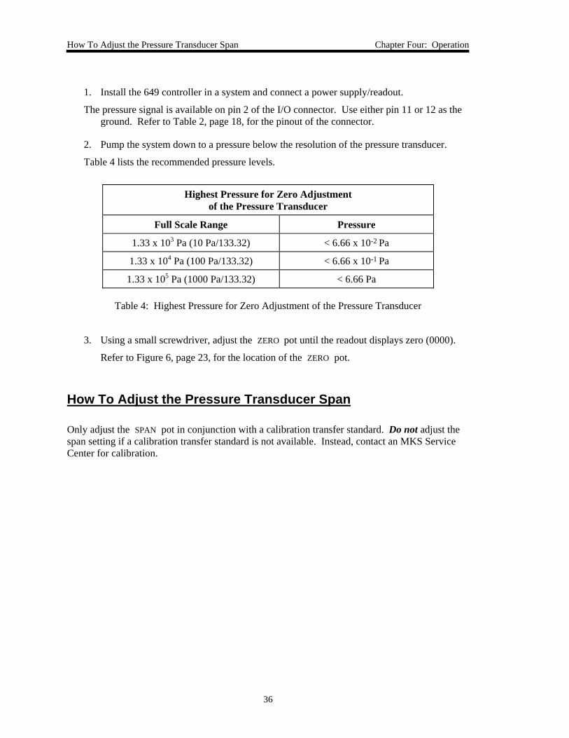
2. Pump the system down to a pressure below the resolution of the pressure transducer.
Table 4 lists the recommended pressure levels.
Highest Pressure for Zero Adjustment of the Pressure Transducer
Full Scale Range Pressure
1.33 x 10³ Pa (10 Pa/133.32) < 6.66 x 10⁻² Pa
1.33 x 10⁴ Pa (100 Pa/133.32) < 6.66 x 10⁻¹ Pa
1.33 x 10⁵ Pa (1000 Pa/133.32) < 6.66 Pa
Table 4: Highest Pressure for Zero Adjustment of the Pressure Transducer
3. Using a small screwdriver, adjust the ZERO pot until the readout displays zero (0000).
Refer to Figure 6, page 23, for the location of the ZERO pot.
How To Adjust the Pressure Transducer Span
Only adjust the SPAN pot in conjunction with a calibration transfer standard. Do not adjust the span setting if a calibration transfer standard is not available. Instead, contact an MKS Service Center for calibration.
Chapter Four: Operation How To Zero the Integral Mass Flow Meter
37
How To Zero the Integral Mass Flow Meter
Ensure that no gas flow is entering the 649 controller.
1. Apply gas, at a regulated pressure, to the 649 controller.
2. Close the positive shutoff valve downstream of the instrument.
3. Command the control valve open by connecting the valve open pin to signal ground.
On the Type “D” connector, connect pin 4 (valve open) to pin 11 or 12 (signal ground). A positive flow may occur momentarily while the gas pressure equalizes across the 649 controller.
Adjust the Zero
1. Once flow through the controller has stopped (reached zero flow), remove the valve open command.
2. Turn the ZERO pot (located on the side of the controller) until the readout displays zero.
Refer to Figure 3, page 14, for the location of the ZERO pot.
3. Open the positive shutoff valve.
The controller may indicate a small, positive flow (<2.0% F.S.) due to a leak through its control valve. However, do not “zero out” this flow since it represents an actual flow measurement inherent in the system.
How To Tune the 649 Controller Chapter Four: Operation
38
How To Tune the 649 Controller
You may need to tune the 649 controller to optimize how it controls your system. Tuning consists of varying the P (Proportional) and I (Integral) parameters to achieve the fastest, smoothest response to changes in the set point value. Ideally, the 649 controller should respond to a new set point value by rapidly changing the pressure in the system to match the set point with little under or overshoot. Refer to How The 649 Pressure Controller Works, page 25, and Tuning the 649 Pressure Controller, page 27, for a complete description of the effects of the P and I terms.
The P term and the I term are initially set to position 0. The controls are located on the top of the unit, as shown in Figure 6, page 23. Each control has a 10-position dial. The P term has only 8 values; positions 8 and 9 repeat the values of positions 0 and 1.
1. Send your set point signal.
If you are using multiple set points send the most critical set point.
2. Change the set point in the direction that you expect the system to deviate in, and observe the controller response.
A properly tuned controller will reach the new set point rapidly, without overshoot.
• If the controller is too slow to reach the set point, increase the P term.
• If the pressure fluctuates around the set point, decrease the P term.
• If the pressure overshoots the set point and then settles to the correct pressure, increase the I term.
3. Repeat steps 1 and 2 until the response of the controller is optimized.
4. Change the set point in the opposite direction, and observe the response.
Although the response may vary slightly, it should be acceptable. If it is not acceptable, follow the guidelines in steps 1 and 2 to tune the controller.
Chapter Four: Operation How To Adjust the Trip Point Values
39
How To Adjust the Trip Point Values
Equipment required: digital volt meter (DVM)
4.8 mm hex or open-ended wrench
Caution
Only qualified individuals should perform the adjustments. You must comply with all the necessary ESD and handling precautions while adjusting the instrument. Proper handling is essential when working with all highly sensitive precision electronic instruments.
Each trip point has a test jack that allows you to measure the trip point setting. The test jacks are located inside the unit. Figure 14, page 41, shows the location of the test jacks and a ground connection. The trip point adjustment pots, located on the top of the unit, allow you to vary the trip point setting.
The range of the trip point setting is 0 to 5 Volts, corresponding to 0 to 100% of pressure transducer full scale.
Note
The trip point range is from 0 to 5 Volts, regardless of the range of the set point input and pressure output signals.
1. Stop the gas flow through the 649 controller.
2. Remove any leads or wires attached to the connector on the 649 controller.
3. Use a 4.8 mm hex wrench (or open-ended wrench) to remove the hex nuts on each side of the I/O connector.
Refer to Figure 6, page 23, for the location of the hex nuts on the I/O connector. Place the hex nuts aside for safe keeping.
4. Position the controller with the front side facing you, and pull up on the enclosure to remove it.
The board assembly will be visible, with the Transducer board facing you and the Control board behind it.
5. Insert the positive test probe into the test jack labeled “TP A” and the ground probe into the test jack labeled “Gnd.”
Insert the probes sufficiently to obtain a good reading. There is no back plane in the test jacks to stop the probe.
6. Use a small screwdriver to adjust the trip point adjustment pot labeled “TP A”.
How To Select the Trip Point Action Chapter Four: Operation
40
Refer to Figure 6, page 23, for the location of the trip point adjustment pots. Turning the pot clockwise raises the trip point setting.
7. Repeat steps 1 and 2 to adjust TP B.
8. Slide the enclosure over the unit and press it in place.
9. Attach the hex nuts, removed in step 3, to the I/O connector.
10. Reconnect the leads and wires.
Refer to How To Select the Trip Point Action, page 40, to change the action of the trip points.
How To Select the Trip Point Action
Equipment required: 4.8 mm hex or open-ended wrench
The 649 controller is initially configured with TP A set to trip high (it is on when the pressure is above the trip point pressure) and TP B set to trip low (it is on when the pressure is below the trip point pressure). To change the action of the trip points you must remove the cover of the unit and change jumpers on the Transducer board. Each trip point has a jumper block with the jumper positions labeled TL (trip low) and TH (trip high).
1. Stop the gas flow through the 649 controller.
2. Remove any leads or wires attached to the connector on the 649 controller.
3. Use a 4.8 mm hex wrench (or open-ended wrench) to remove the hex nuts on each side of the I/O connector.
Refer to Figure 6, page 23, for the location of the hex nuts on the I/O connector. Place the hex nuts aside for safe keeping.
4. Position the controller with the front side facing you, and pull up on the enclosure to remove it.
The board assembly will be visible, with the Transducer board facing you and the Control board behind it.
5. Locate the jumper blocks labeled “JP4” and “JP3” in the middle of the Transducer board.
Refer to Figure 14 for the location of the jumper blocks.
Chapter Four: Operation How To Select the Trip Point Action
41
JP4 Jumper Blocksets TPA action
JP3 Jumper Blocksets TPB action
Jumpers Block JP1 and JP2determine the range of the
pressure output signal
Figure 14: Jumper Positions on the Transducer Board
5. Position the jumper on jumper block “JP4” to select the action for TP A. Jumper block “JP3” controls TP B.
The board silkscreening defines the jumper positions. TH indicates that the trip point will be on when the pressure is above the trip point, and TL indicates that the trip point will be on when the pressure is below the trip point.
6. Slide the enclosure over the unit and press it in place.
7. Attach the hex nuts, removed in step 3, to the I/O connector.
8. Reconnect the leads and wires.

How To Use Trip Points as Error Indicators Chapter Four: Operation
42
How To Use Trip Points as Error Indicators
You can use the trip points to indicate when the error signal deviates from a given range. The error is defined as the difference between the actual pressure reading and the set point.
For example, assume you have a 13.33 kPa unit and your set point is 6.666 kPa. You want the trip points to illuminate when the error is more than ±5% of the set point value, which indicates that the pressure reading has deviated by more than ±0.333 kPa. This allows the pressure to vary from 6.333 to 6.999 kPa.
The 649 controller is initially configured with TP A on above the trip point and TP B on below the trip point. If you have not changed the action of either trip point, you may follow the steps below. If you have changed the action of the trip points, you need to reset them back to the initial configuration for this example. Refer to How To Adjust the Trip Point Values, page 37, for instructions.
1. Calculate the trip point voltage that corresponds to each trip point value:
Trip Point Pressure (Torr)Full Scale Pressure (Torr)
x TP Adjustment Range (V) = Trip Point Voltage (V)
where the full scale pressure is 13.33 kPa and the TP adjustment range is 5 Volts.
TP A: 6.999 kPa13.33 kPa
5 V 2.625 Volts× =
TP B: 6.333 kPa13.33 kPa
5 V Volts× = 2 375.
2. Measure the value of TP A by inserting a positive test probe into the test jack labeled “TP A” and the ground probe into the test jack labeled “Gnd.”
The ground connection and the test jacks are located inside the unit on the Transducer board, as shown Figure 14, page 39. A 0 to 5 V signal corresponds to a 0 to 100% full scale pressure.
3. Use a small screwdriver to adjust the pot for TP A, located on the top of the unit, to set TP A to 2.625 Volts.
Refer to Figure 6, page 21, for the location of the trip point adjustments.
4. Measure the value of TP B by inserting a positive test probe into the test jack labeled “TP B” and the ground probe into the test jack labeled “Gnd.”
5. Use a small screwdriver to adjust the pot for TP B, to set TP B to 2.375 Volts.
The trip points will be off when the pressure reading is between 6.333 to 6.999 kPa. Should the pressure deviate from this range the appropriate trip point will turn on and its LED will illuminate. Trip Point A will turn on when the pressure exceeds 6.999 kPa and Trip Point B will turn on when the pressure falls below 6.333 kPa.
Chapter Four: Operation How To Change the Pressure Output Signal Range
43
How To Change the Pressure Output Signal Range
The pressure output signal can be a 0 to 10 Volt (initial setting) or 0 to 5 Volt signal. To change the range of the pressure output signal, and therefore, the set point input, you must remove the cover of the 649 pressure controller and reposition two jumpers on the Transducer board.
Note
The range of the pressure output signal determines the range used for the set point input signal. The initial configuration is for a 0 to 10 Volt pressure output signal. Therefore, a set point input signal of 10 Volts is equal to 100% of full scale. If you change the range of the pressure output signal to 0 to 5 Volts, a 2.5 Volt set point signal would be 50% of full scale.
1. Stop the gas flow through the 649 pressure controller.
2. Remove the power supply and any other leads or wires attached to the connector on the 649 controller.
3. Use a 4.8 mm hex wrench (or open-ended wrench) to remove the hex nuts on each side of the I/O connector.
Refer to Figure 6, page 23, for the location of the hex nuts on the I/O connector. Place the hex nuts aside for safe keeping.
4. Position the controller with the front side facing you, and pull up on the enclosure to remove it.
The MKS logo is displayed on the front of the unit. The board assembly will be visible, with the Transducer board facing you. The Control board is connected to the back of the Transducer board.
5. Locate the jumper block labeled “JP2” on the right-hand side of the Transducer board.
Refer to Figure 14, page 41, for the location of the “JP2” jumper block.
6. Position the jumper vertically, according to the silkscreening on the board.
Position the jumper on the right-hand side for 0 to 10 Volt operation; the left-hand side for 0 to 5 Volt operation.
7. Locate the jumper block labeled JP1, above jumper block JP2.
8. Position the jumper over the pins for 5 Volt operation.
Remove the jumper on JP1 for 10 Volt operation.
9. Slide the enclosure cover over the unit.
10. Attach the hex nuts, removed in step 3, to the I/O connector.
How To Change the Pressure Output Signal Range Chapter Four: Operation
44
11. Reconnect the leads and wires.
Chapter Five: Maintenance General Information
45
Chapter Five: Maintenance
General Information
Periodically check for wear on the cables and inspect the enclosure for visible signs of damage.
Zero Adjustment
For best accuracy and repeatability, you should check the zero setting for both the pressure transducer and the flow meter periodically and reset it, if necessary. Refer to How To Check the Pressure Transducer Zero, page 35, and How To Zero the Integral Mass Flow Meter, page 37, for instructions on setting the zero. The frequency of checking the zero is dependent on the specific accuracy and repeatability required by your process. It is also recommended that the instrument be recalibrated annually if no other time interval has been specifically established. Refer to the inside of the back cover of this instruction manual for a complete list of MKS Calibration and Service centers.

Zero Adjustment Chapter Five: Maintenance
46
This page intentionally left blank.
Appendix A: Product Specifications Performance Specifications
47
Appendix A: Product Specifications
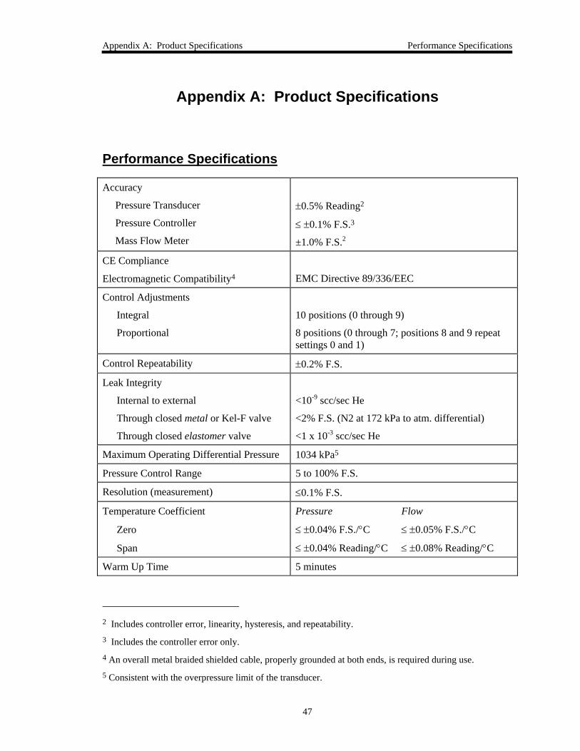
Performance Specifications
Accuracy
Pressure Transducer
Pressure Controller
Mass Flow Meter
±0.5% Reading2
≤ ±0.1% F.S.3
±1.0% F.S.2
CE Compliance
Electromagnetic Compatibility4
EMC Directive 89/336/EEC
Control Adjustments
Integral
Proportional
10 positions (0 through 9)
8 positions (0 through 7; positions 8 and 9 repeat settings 0 and 1)
Control Repeatability ±0.2% F.S.
Leak Integrity
Internal to external
Through closed metal or Kel-F valve
Through closed elastomer valve
<10-9 scc/sec He
<2% F.S. (N2 at 172 kPa to atm. differential)
<1 x 10⁻³ scc/sec He
Maximum Operating Differential Pressure 1034 kPa5
Pressure Control Range 5 to 100% F.S.
Resolution (measurement) ≤0.1% F.S.
Temperature Coefficient
Zero±
Span±
Pressure Flow
≤ ±0.04% F.S./°C ≤ ±0.05% F.S./°C
≤ ±0.04% Reading/°C ≤ ±0.08% Reading/°C
Warm Up Time 5 minutes
2 Includes controller error, linearity, hysteresis, and repeatability. 3 Includes the controller error only. 4 An overall metal braided shielded cable, properly grounded at both ends, is required during use. 5 Consistent with the overpressure limit of the transducer.
Physical Specifications Appendix A: Product Specifications
48
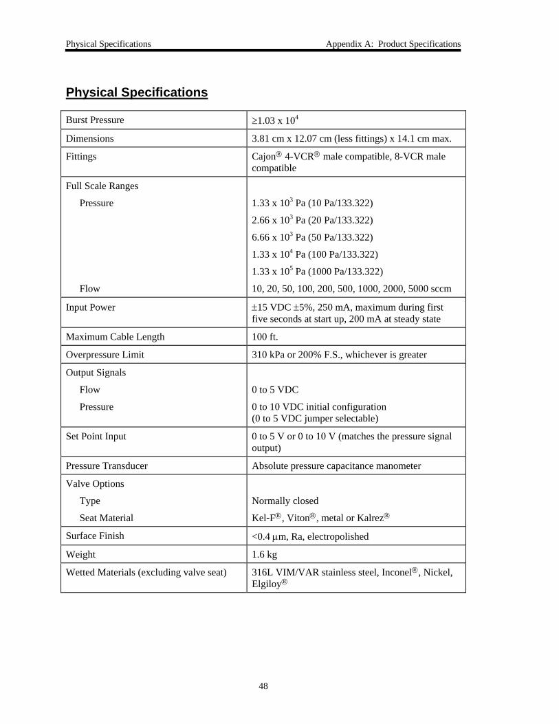
Physical Specifications
Burst Pressure ≥1.03 x 10⁴
Dimensions 3.81 cm x 12.07 cm (less fittings) x 14.1 cm max.
Fittings Cajon® 4-VCR® male compatible, 8-VCR male compatible
Full Scale Ranges
Pressure
Flow
1.33 x 10³ Pa (10 Pa/133.322)
2.66 x 10³ Pa (20 Pa/133.322)
6.66 x 10³ Pa (50 Pa/133.322)
1.33 x 10⁴ Pa (100 Pa/133.322)
1.33 x 10⁵ Pa (1000 Pa/133.322)
10, 20, 50, 100, 200, 500, 1000, 2000, 5000 sccm
Input Power± ±15 VDC ±5%, 250 mA, maximum during first five seconds at start up, 200 mA at steady state
Maximum Cable Length 100 ft.
Overpressure Limit 310 kPa or 200% F.S., whichever is greater
Output Signals
Flow
Pressure
0 to 5 VDC
0 to 10 VDC initial configuration (0 to 5 VDC jumper selectable)
Set Point Input 0 to 5 V or 0 to 10 V (matches the pressure signal output)
Pressure Transducer Absolute pressure capacitance manometer
Valve Options
Type
Seat Material
Normally closed
Kel-F®, Viton®, metal or Kalrez®
Surface Finish <0.4 μm, Ra, electropolished
Weight 1.6 kg
Wetted Materials (excluding valve seat) 316L VIM/VAR stainless steel, Inconel®, Nickel, Elgiloy®
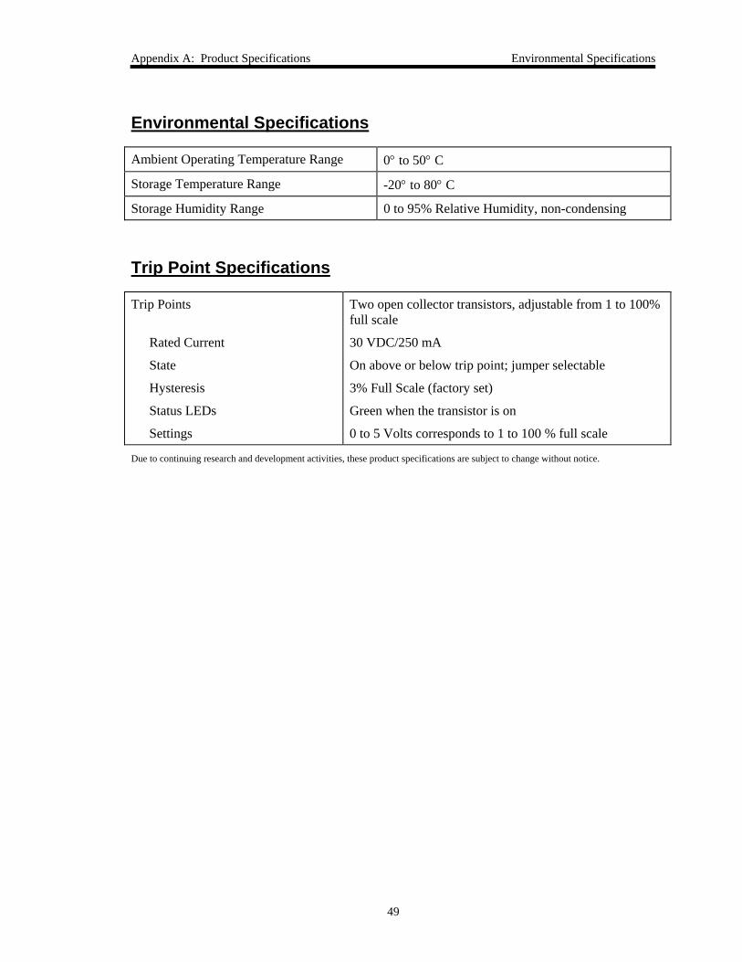
Appendix A: Product Specifications Environmental Specifications
49
Environmental Specifications
Ambient Operating Temperature Range 0° to 50° C
Storage Temperature Range -20° to 80° C
Storage Humidity Range 0 to 95% Relative Humidity, non-condensing
Trip Point Specifications
Trip Points
Rated Current
State
Hysteresis
Status LEDs
Settings
Two open collector transistors, adjustable from 1 to 100% full scale
30 VDC/250 mA
On above or below trip point; jumper selectable
3% Full Scale (factory set)
Green when the transistor is on
0 to 5 Volts corresponds to 1 to 100 % full scale
Due to continuing research and development activities, these product specifications are subject to change without notice.

Trip Point Specifications Appendix A: Product Specifications
50
This page intentionally left blank.
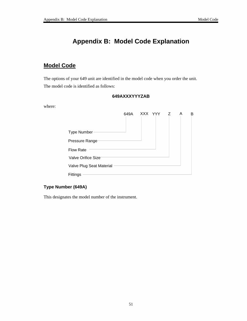
Appendix B: Model Code Explanation Model Code
51
Appendix B: Model Code Explanation
Model Code
The options of your 649 unit are identified in the model code when you order the unit.
The model code is identified as follows:
649AXXXYYYZAB
where:
Type Number
Pressure Range
Flow Rate
ZXXX YYY649A
Valve Orifice Size
Valve Plug Seat Material
A B
Fittings
Type Number (649A)
This designates the model number of the instrument.
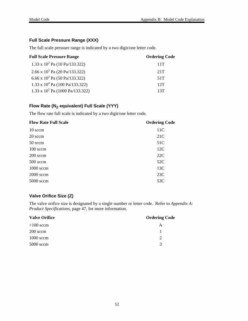
Model Code Appendix B: Model Code Explanation
52
Full Scale Pressure Range (XXX) The full scale pressure range is indicated by a two digit/one letter code.
Full Scale Pressure Range Ordering Code
1.33 x 10³ Pa (10 Pa/133.322) 11T
2.66 x 10³ Pa (20 Pa/133.322) 21T 6.66 x 10³ Pa (50 Pa/133.322) 51T 1.33 x 10⁴ Pa (100 Pa/133.322) 12T 1.33 x 10⁵ Pa (1000 Pa/133.322) 13T
Flow Rate (N2 equivalent) Full Scale (YYY) The flow rate full scale is indicated by a two digit/one letter code.
Flow Rate Full Scale Ordering Code
10 sccm 11C 20 sccm 21C 50 sccm 51C 100 sccm 12C 200 sccm 22C 500 sccm 52C 1000 sccm 13C 2000 sccm 23C 5000 sccm 53C
Valve Orifice Size (Z) The valve orifice size is designated by a single number or letter code. Refer to Appendix A: Product Specifications, page 47, for more information.
Valve Orifice Ordering Code
<100 sccm A 200 sccm 1 1000 sccm 2 5000 sccm 3
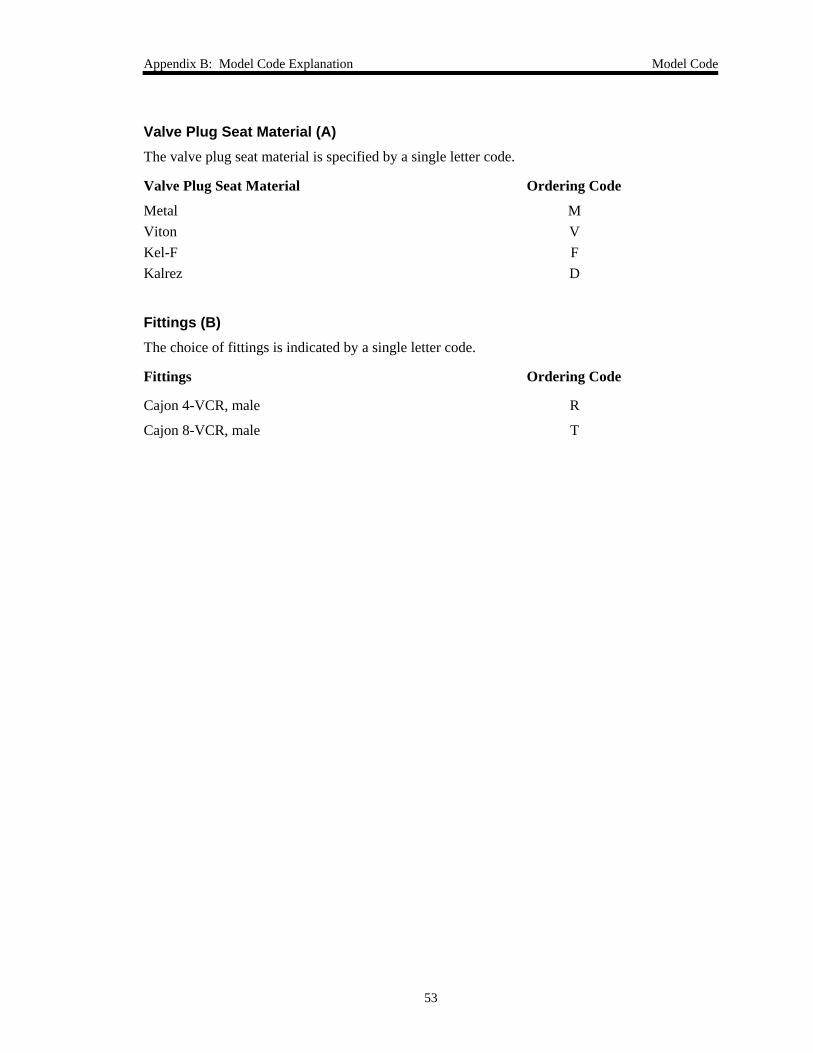
Appendix B: Model Code Explanation Model Code
53
Valve Plug Seat Material (A) The valve plug seat material is specified by a single letter code.
Valve Plug Seat Material Ordering Code
Metal M Viton V Kel-F F Kalrez D
Fittings (B) The choice of fittings is indicated by a single letter code.
Fittings Ordering Code
Cajon 4-VCR, male R
Cajon 8-VCR, male T

Model Code Appendix B: Model Code Explanation
54
This page intentionally left blank.
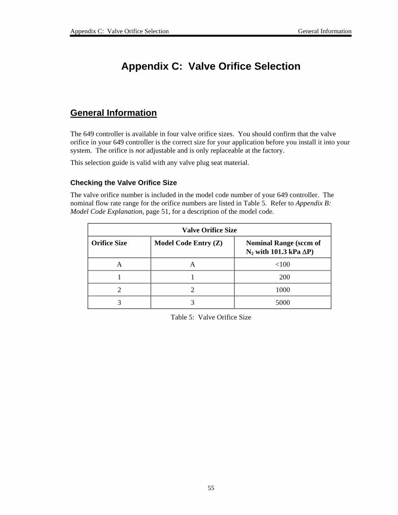
Appendix C: Valve Orifice Selection General Information
55
Appendix C: Valve Orifice Selection
General Information
The 649 controller is available in four valve orifice sizes. You should confirm that the valve orifice in your 649 controller is the correct size for your application before you install it into your system. The orifice is not adjustable and is only replaceable at the factory.
This selection guide is valid with any valve plug seat material.
Checking the Valve Orifice Size The valve orifice number is included in the model code number of your 649 controller. The nominal flow rate range for the orifice numbers are listed in Table 5. Refer to Appendix B: Model Code Explanation, page 51, for a description of the model code.
Valve Orifice Size
Orifice Size Model Code Entry (Z) Nominal Range (sccm of N2 with 101.3 kPa ΔP)
A A <100
1 1 200
2 2 1000
3 3 5000
Table 5: Valve Orifice Size
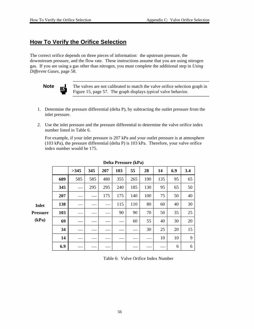
How To Verify the Orifice Selection Appendix C: Valve Orifice Selection
56
How To Verify the Orifice Selection
The correct orifice depends on three pieces of information: the upstream pressure, the downstream pressure, and the flow rate. These instructions assume that you are using nitrogen gas. If you are using a gas other than nitrogen, you must complete the additional step in Using Different Gases, page 58.
Note
The valves are not calibrated to match the valve orifice selection graph in Figure 15, page 57. The graph displays typical valve behavior.
1. Determine the pressure differential (delta P), by subtracting the outlet pressure from the inlet pressure.
2. Use the inlet pressure and the pressure differential to determine the valve orifice index number listed in Table 6.
For example, if your inlet pressure is 207 kPa and your outlet pressure is at atmosphere (103 kPa), the pressure differential (delta P) is 103 kPa. Therefore, your valve orifice index number would be 175.
Delta Pressure (kPa)
>345 345 207 103 55 28 14 6.9 3.4
689 585 585 480 355 265 190 135 95 65
345 ⎯ 295 295 240 185 130 95 65 50
207 ⎯ ⎯ 175 175 140 100 75 50 40
Inlet 138 ⎯ ⎯ ⎯ 115 110 80 60 40 30
Pressure 103 ⎯ ⎯ ⎯ 90 90 70 50 35 25 (kPa) 69 ⎯ ⎯ ⎯ ⎯ 60 55 40 30 20
34 ⎯ ⎯ ⎯ ⎯ ⎯ 30 25 20 15
14 ⎯ ⎯ ⎯ ⎯ ⎯ ⎯ 10 10 9
6.9 ⎯ ⎯ ⎯ ⎯ ⎯ ⎯ 6 6
Table 6: Valve Orifice Index Number
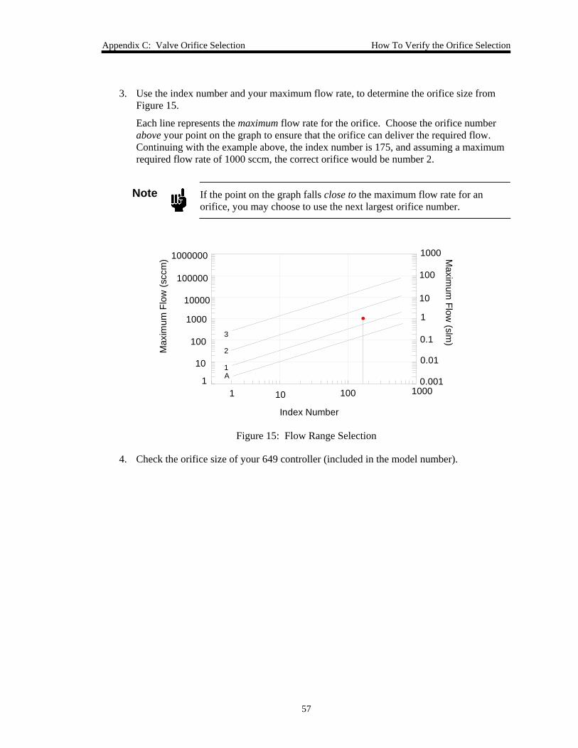
Appendix C: Valve Orifice Selection How To Verify the Orifice Selection
57
3. Use the index number and your maximum flow rate, to determine the orifice size from Figure 15.
Each line represents the maximum flow rate for the orifice. Choose the orifice number above your point on the graph to ensure that the orifice can deliver the required flow. Continuing with the example above, the index number is 175, and assuming a maximum required flow rate of 1000 sccm, the correct orifice would be number 2.
Note
If the point on the graph falls close to the maximum flow rate for an orifice, you may choose to use the next largest orifice number.
Index Number
Max
imum
Flo
w (s
ccm
) Maxim
um Flow
(slm)
1 10 100 10000.001
0.01
0.1
1
10
100
1000
1
10
100
1000
10000
100000
1000000
3
2
1A
Figure 15: Flow Range Selection
4. Check the orifice size of your 649 controller (included in the model number).
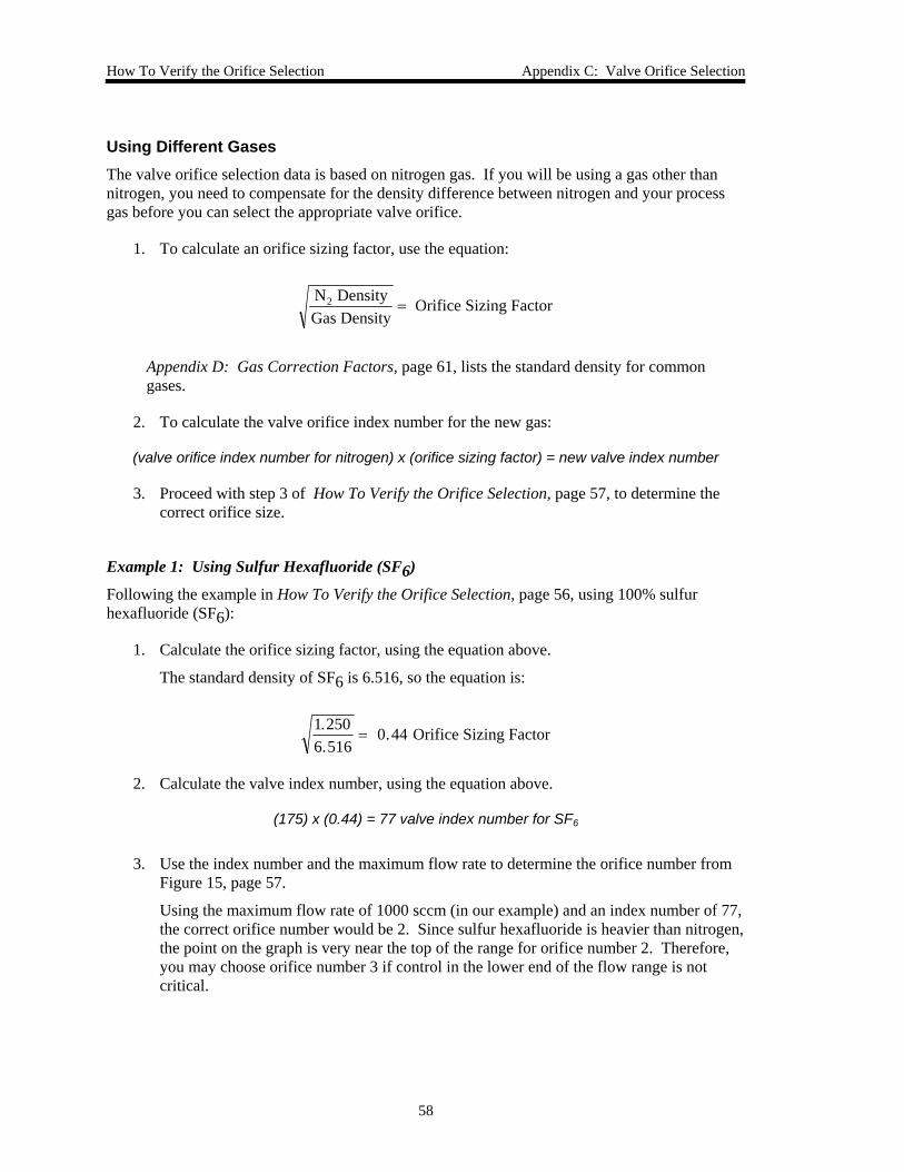
How To Verify the Orifice Selection Appendix C: Valve Orifice Selection
58
Using Different Gases The valve orifice selection data is based on nitrogen gas. If you will be using a gas other than nitrogen, you need to compensate for the density difference between nitrogen and your process gas before you can select the appropriate valve orifice.
1. To calculate an orifice sizing factor, use the equation:
N DensityGas Density
Orifice Sizing Factor2 =
Appendix D: Gas Correction Factors, page 61, lists the standard density for common gases.
2. To calculate the valve orifice index number for the new gas:
(valve orifice index number for nitrogen) x (orifice sizing factor) = new valve index number
3. Proceed with step 3 of How To Verify the Orifice Selection, page 57, to determine the correct orifice size.
Example 1: Using Sulfur Hexafluoride (SF6)
Following the example in How To Verify the Orifice Selection, page 56, using 100% sulfur hexafluoride (SF6):
1. Calculate the orifice sizing factor, using the equation above.
The standard density of SF6 is 6.516, so the equation is:
1.2506.516
0.44 Orifice Sizing Factor=
2. Calculate the valve index number, using the equation above.
(175) x (0.44) = 77 valve index number for SF6
3. Use the index number and the maximum flow rate to determine the orifice number from Figure 15, page 57.
Using the maximum flow rate of 1000 sccm (in our example) and an index number of 77, the correct orifice number would be 2. Since sulfur hexafluoride is heavier than nitrogen, the point on the graph is very near the top of the range for orifice number 2. Therefore, you may choose orifice number 3 if control in the lower end of the flow range is not critical.
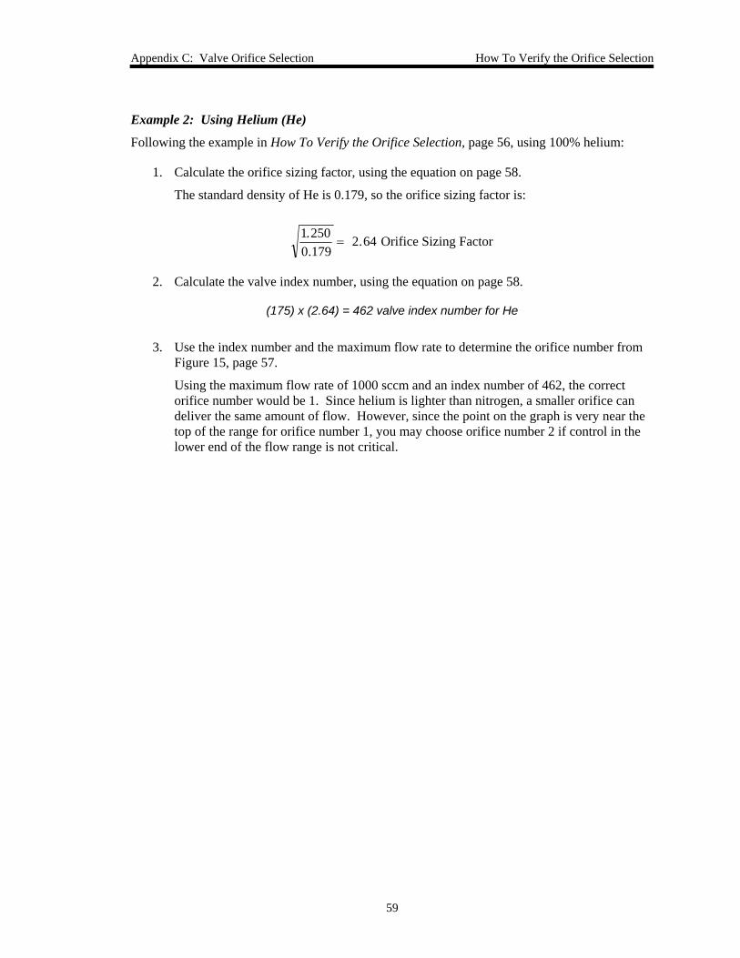
Appendix C: Valve Orifice Selection How To Verify the Orifice Selection
59
Example 2: Using Helium (He)
Following the example in How To Verify the Orifice Selection, page 56, using 100% helium:
1. Calculate the orifice sizing factor, using the equation on page 58.
The standard density of He is 0.179, so the orifice sizing factor is:
1.2500.179
2.64 Orifice Sizing Factor=
2. Calculate the valve index number, using the equation on page 58.
(175) x (2.64) = 462 valve index number for He
3. Use the index number and the maximum flow rate to determine the orifice number from Figure 15, page 57.
Using the maximum flow rate of 1000 sccm and an index number of 462, the correct orifice number would be 1. Since helium is lighter than nitrogen, a smaller orifice can deliver the same amount of flow. However, since the point on the graph is very near the top of the range for orifice number 1, you may choose orifice number 2 if control in the lower end of the flow range is not critical.
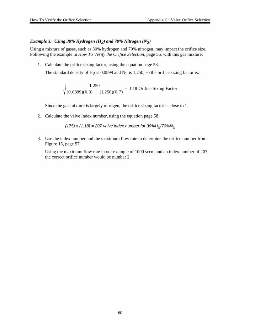
How To Verify the Orifice Selection Appendix C: Valve Orifice Selection
60
Example 3: Using 30% Hydrogen (H2) and 70% Nitrogen (N2)
Using a mixture of gases, such as 30% hydrogen and 70% nitrogen, may impact the orifice size. Following the example in How To Verify the Orifice Selection, page 56, with this gas mixture:
1. Calculate the orifice sizing factor, using the equation page 58.
The standard density of H2 is 0.0899 and N2 is 1.250, so the orifice sizing factor is:
1.250(0.0899)(0.3) + (1.250)(0.7)
1.18 Orifice Sizing Factor=
Since the gas mixture is largely nitrogen, the orifice sizing factor is close to 1.
2. Calculate the valve index number, using the equation page 58.
(175) x (1.18) = 207 valve index number for 30%H2/70%N2
3. Use the index number and the maximum flow rate to determine the orifice number from Figure 15, page 57.
Using the maximum flow rate in our example of 1000 sccm and an index number of 207, the correct orifice number would be number 2.
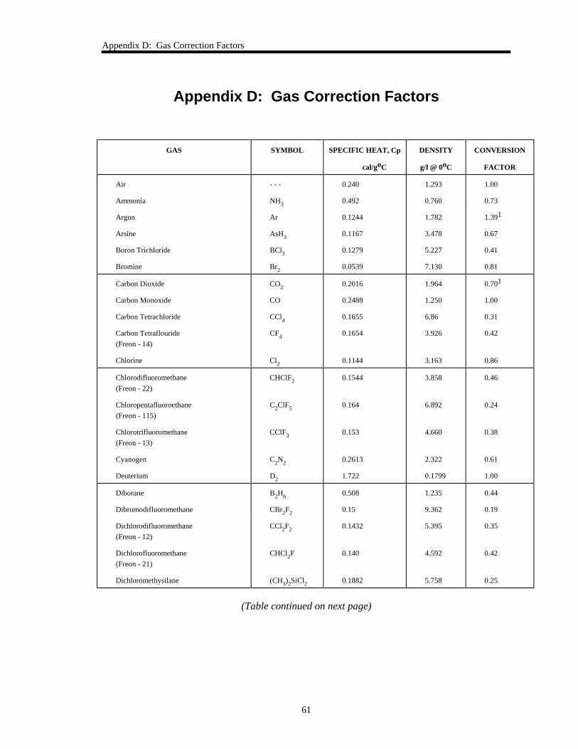
Appendix D: Gas Correction Factors
61
Appendix D: Gas Correction Factors
GAS SYMBOL SPECIFIC HEAT, Cp
cal/goC
DENSITY
g/l @ 0oC
CONVERSION
FACTOR
Air
Ammonia
- - -
NH3
0.240
0.492
1.293
0.760
1.00
0.73
Argon
Arsine
Boron Trichloride
Bromine
Ar
AsH3
BCl3
Br2
0.1244
0.1167
0.1279
0.0539
1.782
3.478
5.227
7.130
1.391
0.67
0.41
0.81
Carbon Dioxide
Carbon Monoxide
Carbon Tetrachloride
Carbon Tetraflouride (Freon - 14)
Chlorine
CO2
CO
CCl4
CF4
Cl2
0.2016
0.2488
0.1655
0.1654
0.1144
1.964
1.250
6.86
3.926
3.163
0.701
1.00
0.31
0.42
0.86
Chlorodifluoromethane (Freon - 22)
Chloropentafluoroethane (Freon - 115)
Chlorotrifluoromethane (Freon - 13)
Cyanogen
Deuterium
CHClF2
C2ClF5
CClF3
C2N2
D2
0.1544
0.164
0.153
0.2613
1.722
3.858
6.892
4.660
2.322
0.1799
0.46
0.24
0.38
0.61
1.00
Diborane
Dibromodifluoromethane
B2H6
CBr2F2
0.508
0.15
1.235
9.362
0.44
0.19
Dichlorodifluoromethane (Freon - 12)
Dichlorofluoromethane (Freon - 21)
Dichloromethysilane
CCl2F2
CHCl2F
(CH3)2SiCl2
0.1432
0.140
0.1882
5.395
4.592
5.758
0.35
0.42
0.25
(Table continued on next page)
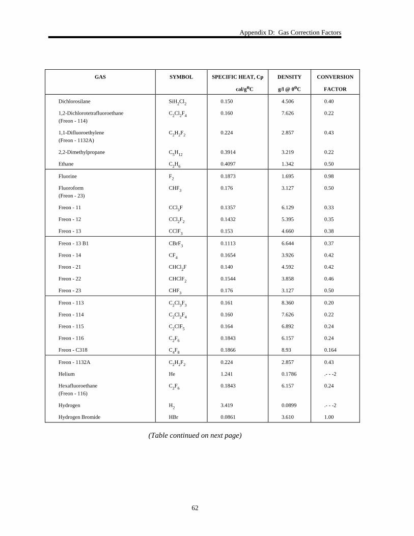
Appendix D: Gas Correction Factors
62
GAS SYMBOL SPECIFIC HEAT, Cp
cal/goC
DENSITY
g/l @ 0oC
CONVERSION
FACTOR
Dichlorosilane
1,2-Dichlorotetrafluoroethane (Freon - 114)
1,1-Difluoroethylene (Freon - 1132A)
2,2-Dimethylpropane
Ethane
SiH2Cl2
C2Cl2F4
C2H2F2
C5H12
C2H6
0.150
0.160
0.224
0.3914
0.4097
4.506
7.626
2.857
3.219
1.342
0.40
0.22
0.43
0.22
0.50
Fluorine
Fluoroform (Freon - 23)
Freon - 11
Freon - 12
Freon - 13
F2
CHF3
CCl3F
CCl2F2
CClF3
0.1873
0.176
0.1357
0.1432
0.153
1.695
3.127
6.129
5.395
4.660
0.98
0.50
0.33
0.35
0.38
Freon - 13 B1
Freon - 14
Freon - 21
Freon - 22
Freon - 23
CBrF3
CF4
CHCl2F
CHClF2
CHF3
0.1113
0.1654
0.140
0.1544
0.176
6.644
3.926
4.592
3.858
3.127
0.37
0.42
0.42
0.46
0.50
Freon - 113
Freon - 114
Freon - 115
Freon - 116
Freon - C318
C2Cl3F3
C2Cl2F4
C2ClF5
C2F6
C4F8
0.161
0.160
0.164
0.1843
0.1866
8.360
7.626
6.892
6.157
8.93
0.20
0.22
0.24
0.24
0.164
Freon - 1132A
Helium
Hexafluoroethane (Freon - 116)
Hydrogen
Hydrogen Bromide
C2H2F2
He
C2F6
H2
HBr
0.224
1.241
0.1843
3.419
0.0861
2.857
0.1786
6.157
0.0899
3.610
0.43
.- - -2
0.24
.- - -2
1.00
(Table continued on next page)
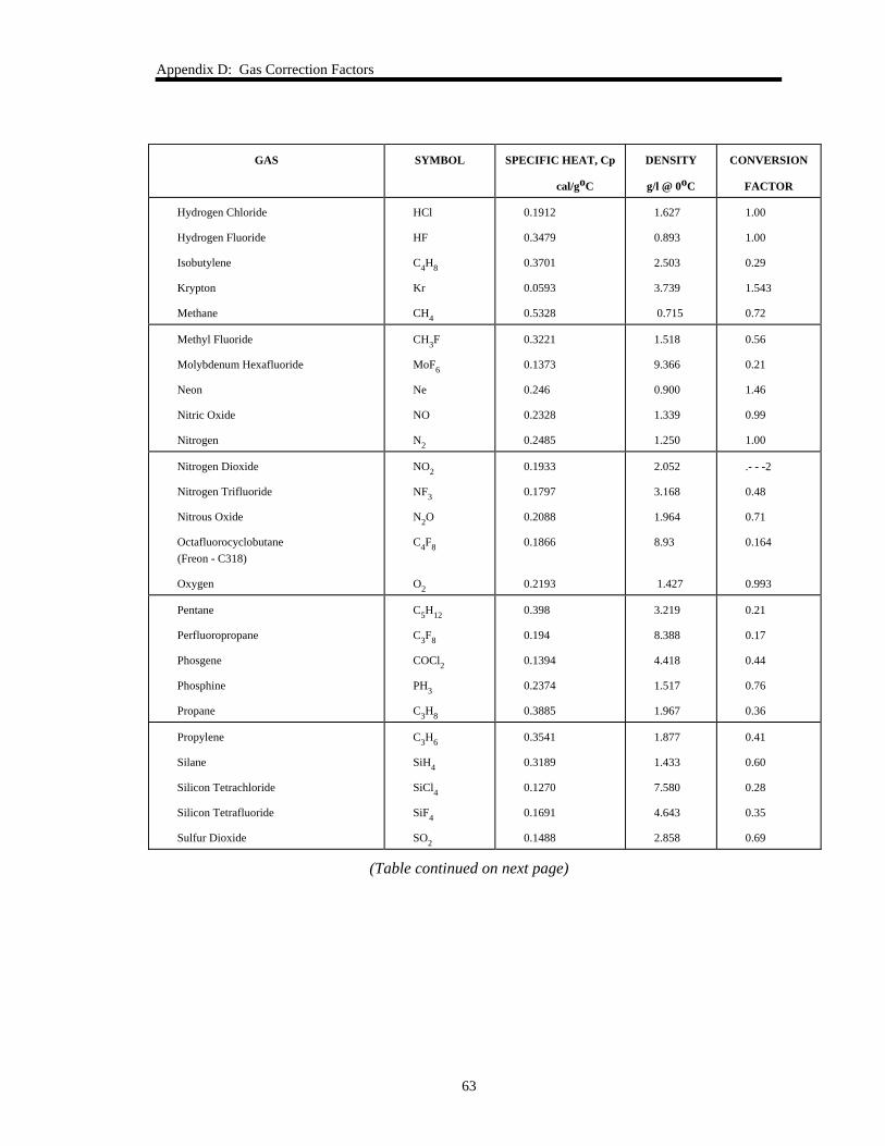
Appendix D: Gas Correction Factors
63
GAS SYMBOL SPECIFIC HEAT, Cp
cal/goC
DENSITY
g/l @ 0oC
CONVERSION
FACTOR
Hydrogen Chloride
Hydrogen Fluoride
Isobutylene
Krypton
Methane
HCl
HF
C4H8
Kr
CH4
0.1912
0.3479
0.3701
0.0593
0.5328
1.627
0.893
2.503
3.739
0.715
1.00
1.00
0.29
1.543
0.72
Methyl Fluoride
Molybdenum Hexafluoride
Neon
Nitric Oxide
Nitrogen
CH3F
MoF6
Ne
NO
N2
0.3221
0.1373
0.246
0.2328
0.2485
1.518
9.366
0.900
1.339
1.250
0.56
0.21
1.46
0.99
1.00
Nitrogen Dioxide
Nitrogen Trifluoride
Nitrous Oxide
Octafluorocyclobutane (Freon - C318)
Oxygen
NO2
NF3
N2O
C4F8
O2
0.1933
0.1797
0.2088
0.1866
0.2193
2.052
3.168
1.964
8.93
1.427
.- - -2
0.48
0.71
0.164
0.993
Pentane
Perfluoropropane
Phosgene
Phosphine
Propane
C5H12
C3F8
COCl2
PH3
C3H8
0.398
0.194
0.1394
0.2374
0.3885
3.219
8.388
4.418
1.517
1.967
0.21
0.17
0.44
0.76
0.36
Propylene
Silane
Silicon Tetrachloride
Silicon Tetrafluoride
Sulfur Dioxide
C3H6
SiH4
SiCl4
SiF4
SO2
0.3541
0.3189
0.1270
0.1691
0.1488
1.877
1.433
7.580
4.643
2.858
0.41
0.60
0.28
0.35
0.69
(Table continued on next page)
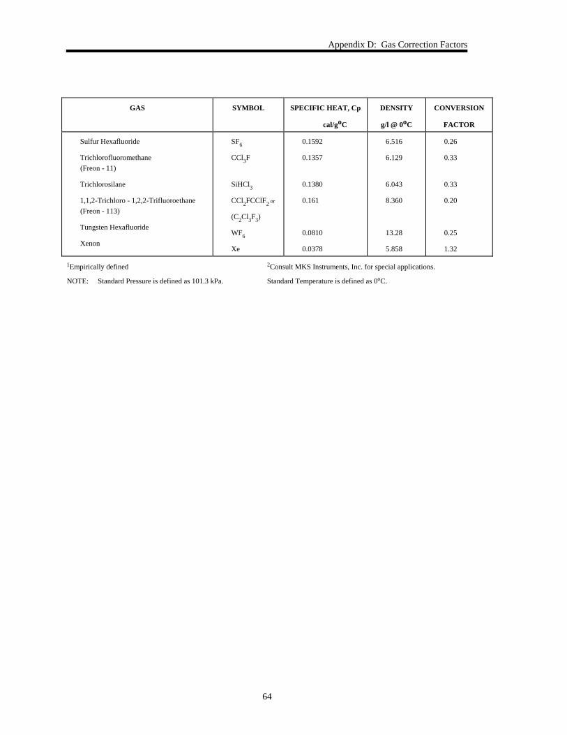
Appendix D: Gas Correction Factors
64
GAS SYMBOL SPECIFIC HEAT, Cp
cal/goC
DENSITY
g/l @ 0oC
CONVERSION
FACTOR
Sulfur Hexafluoride
Trichlorofluoromethane (Freon - 11)
Trichlorosilane
1,1,2-Trichloro - 1,2,2-Trifluoroethane (Freon - 113)
Tungsten Hexafluoride
Xenon
SF6
CCl3F
SiHCl3
CCl2FCClF2 or
(C2Cl3F3)
WF6
Xe
0.1592
0.1357
0.1380
0.161
0.0810
0.0378
6.516
6.129
6.043
8.360
13.28
5.858
0.26
0.33
0.33
0.20
0.25
1.32
1Empirically defined 2Consult MKS Instruments, Inc. for special applications.
NOTE: Standard Pressure is defined as 101.3 kPa. Standard Temperature is defined as 0oC.
Index
65
Index
A
Accuracy, 51
Ambient temperature, 12, 47
B
Baratron, 5
C
Commands, priority, 29
Connector, I/O, 18–19
Control range, pressure, 21
Control system, 22
Customer support, 7
D
Differential pressure, 31, 54
Dimensions, 13
Downstream control, 17
E
Electrical information, 50
F
Fittings, 16, 50, 51
Flow arrow, 13, 17
Flow output signal, 19, 20
Flow path, 24
Flow range, 22, 24
G
Gas correction factor, 32, 59
I
I/O connector, 18
Inlet pressure, 16
Installation, 13
Integral control, 20, 21, 23, 26, 27, 36
L
Label, 31
M
Manual conventions, 6
Manual organization, 6
Measurement technique, 24
Model code, 49
Mounting, 16, 17
O
Optional input, 19
Orientation, 12, 17, 33
Overpressure limit, 31
P
PI control, 23
Pinout, I/O connector, 18
Power, 50
Pressure control signal, 21
Pressure output range, 41
Pressure output signal, 18, 20
Pressure, inlet, 16
Process control, 20, 23–26
Proportional control, 20, 21, 23, 25, 27, 36
Index
66
R
Range, 50
Returning the product, 7, 9
S
Safety procedures and precautions, 2
Set point, 19
Set point input, 20
Set point recognition, 29
Span adjustment, 34
Specifications
environmental, 47
physical, 46
trip points, 47
T
Transducer board, 38
Trip point action, 38
Trip point values, 37
Trip points, 19, 20, 30
Tuning, 25–28
U
Unpacking
opening, 9
V
Valve commands, 29
Valve orifice, 53–58
Valve test point, 18
Z
Zero
mass flow meter, 35
transducer, 33–34