Embed Size (px)
DESCRIPTION
mechanical
Citation preview

M-D Pneumatics™
Models
INSTALLATIONOPERATIONMAINTENANCEREPAIR
MANUAL
7010 7013 7017 7021 7026
Rotary Positive Displacement Blower17/19 Horizontal Air Flow46/86 Vertical Air Flow55/57 Horizontal Flow, Single Envelope Gastight81/82 Vertical Flow, Single Envelope Gastight64/66 Horizontal Flow, Double Envelope Gastight67/69 Vertical Flow, Double Envelope Gastight
4840 West Kearney Street, P. O. Box 2877Springfield, Missouri USA 65801-2877Tel 417 865-8715 800 825-6937 Fax 417 865-2950http://vacuum.tuthill.com20
07 0
911
OR
IGIN
AL
LAN
GU
AG
E - E
NG
LISH
INTERNATIONAL QUALITY STANDARD
REGISTERED
VACUUM & BLOWER SYSTEMS
TUTHILL CORPORATION
2
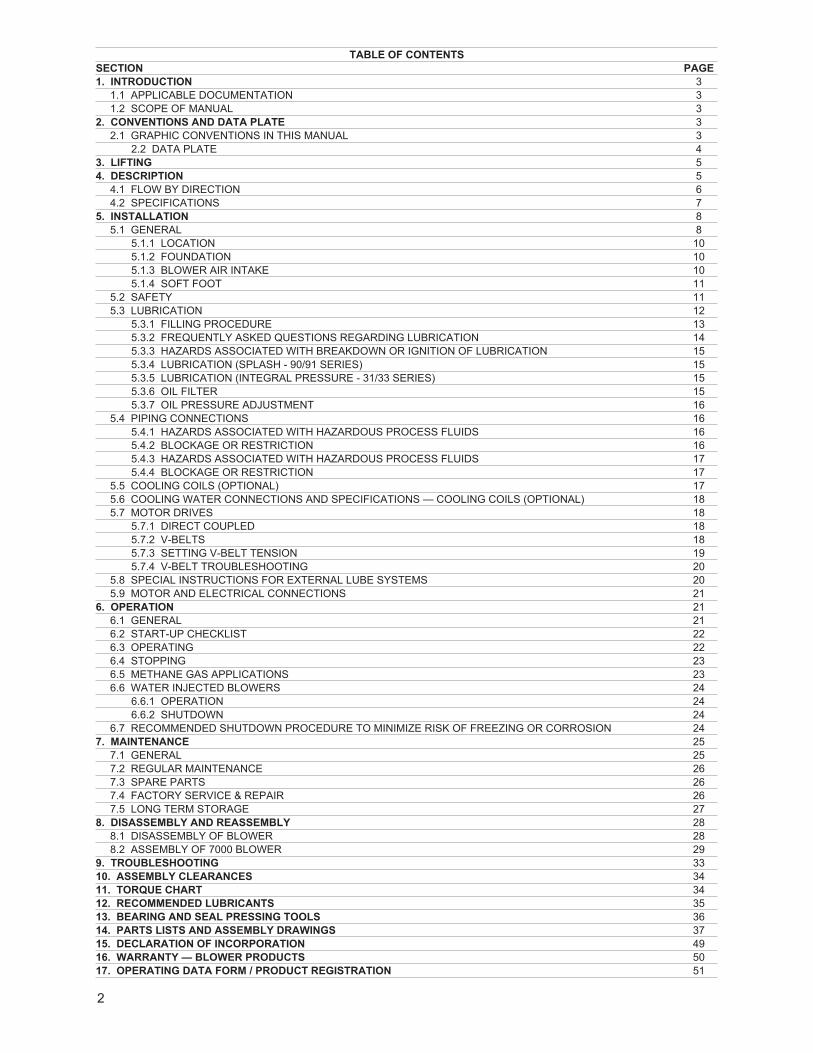
TABLE OF CONTENTSSECTION PAGE1. INTRODUCTION 3
1.1 APPLICABLE DOCUMENTATION 31.2 SCOPE OF MANUAL 3
2. CONVENTIONS AND DATA PLATE 32.1 GRAPHIC CONVENTIONS IN THIS MANUAL 3
2.2 DATA PLATE 43. LIFTING 54. DESCRIPTION 5
4.1 FLOW BY DIRECTION 64.2 SPECIFICATIONS 7
5. INSTALLATION 85.1 GENERAL 8
5.1.1 LOCATION 105.1.2 FOUNDATION 105.1.3 BLOWER AIR INTAKE 105.1.4 SOFT FOOT 11
5.2 SAFETY 115.3 LUBRICATION 12
5.3.1 FILLING PROCEDURE 135.3.2 FREQUENTLY ASKED QUESTIONS REGARDING LUBRICATION 145.3.3 HAZARDS ASSOCIATED WITH BREAKDOWN OR IGNITION OF LUBRICATION 155.3.4 LUBRICATION (SPLASH - 90/91 SERIES) 155.3.5 LUBRICATION (INTEGRAL PRESSURE - 31/33 SERIES) 155.3.6 OIL FILTER 155.3.7 OIL PRESSURE ADJUSTMENT 16
5.4 PIPING CONNECTIONS 165.4.1 HAZARDS ASSOCIATED WITH HAZARDOUS PROCESS FLUIDS 165.4.2 BLOCKAGE OR RESTRICTION 165.4.3 HAZARDS ASSOCIATED WITH HAZARDOUS PROCESS FLUIDS 175.4.4 BLOCKAGE OR RESTRICTION 17
5.5 COOLING COILS (OPTIONAL) 175.6 COOLING WATER CONNECTIONS AND SPECIFICATIONS — COOLING COILS (OPTIONAL) 185.7 MOTOR DRIVES 18
5.7.1 DIRECT COUPLED 185.7.2 V-BELTS 185.7.3 SETTING V-BELT TENSION 195.7.4 V-BELT TROUBLESHOOTING 20
5.8 SPECIAL INSTRUCTIONS FOR EXTERNAL LUBE SYSTEMS 205.9 MOTOR AND ELECTRICAL CONNECTIONS 21
6. OPERATION 216.1 GENERAL 216.2 START-UP CHECKLIST 226.3 OPERATING 226.4 STOPPING 236.5 METHANE GAS APPLICATIONS 236.6 WATER INJECTED BLOWERS 24
6.6.1 OPERATION 246.6.2 SHUTDOWN 24
6.7 RECOMMENDED SHUTDOWN PROCEDURE TO MINIMIZE RISK OF FREEZING OR CORROSION 247. MAINTENANCE 25
7.1 GENERAL 257.2 REGULAR MAINTENANCE 267.3 SPARE PARTS 267.4 FACTORY SERVICE & REPAIR 267.5 LONG TERM STORAGE 27
8. DISASSEMBLY AND REASSEMBLY 288.1 DISASSEMBLY OF BLOWER 288.2 ASSEMBLY OF 7000 BLOWER 29
9. TROUBLESHOOTING 3310. ASSEMBLY CLEARANCES 3411. TORQUE CHART 3412. RECOMMENDED LUBRICANTS 3513. BEARING AND SEAL PRESSING TOOLS 3614. PARTS LISTS AND ASSEMBLY DRAWINGS 3715. DECLARATION OF INCORPORATION 4916. WARRANTY — BLOWER PRODUCTS 5017. OPERATING DATA FORM / PRODUCT REGISTRATION 51
3
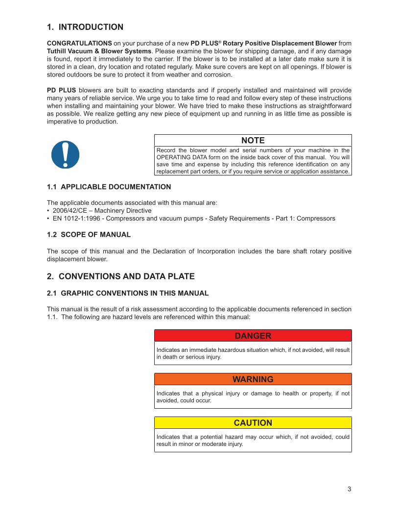
1. INTRODUCTION
CONGRATULATIONS on your purchase of a new PD PLUS® Rotary Positive Displacement Blower from Tuthill Vacuum & Blower Systems. Please examine the blower for shipping damage, and if any damage is found, report it immediately to the carrier. If the blower is to be installed at a later date make sure it is stored in a clean, dry location and rotated regularly. Make sure covers are kept on all openings. If blower is stored outdoors be sure to protect it from weather and corrosion.
PD PLUS blowers are built to exacting standards and if properly installed and maintained will provide many years of reliable service. We urge you to take time to read and follow every step of these instructions when installing and maintaining your blower. We have tried to make these instructions as straightforward as possible. We realize getting any new piece of equipment up and running in as little time as possible is imperative to production.
NOTERecord the blower model and serial numbers of your machine in the OPERATING DATA form on the inside back cover of this manual. You will save time and expense by including this reference identification on any replacement part orders, or if you require service or application assistance.
1.1 APPLICABLE DOCUMENTATION
The applicable documents associated with this manual are:• 2006/42/CE – Machinery Directive• EN 1012-1:1996 - Compressors and vacuum pumps - Safety Requirements - Part 1: Compressors
1.2 SCOPE OF MANUAL
The scope of this manual and the Declaration of Incorporation includes the bare shaft rotary positive displacement blower.
2. CONVENTIONS AND DATA PLATE
2.1 GRAPHIC CONVENTIONS IN THIS MANUAL
This manual is the result of a risk assessment according to the applicable documents referenced in section 1.1. The following are hazard levels are referenced within this manual:
DANGERIndicates an immediate hazardous situation which, if not avoided, will result in death or serious injury.
WARNINGIndicates that a physical injury or damage to health or property, if not avoided, could occur.
CAUTIONIndicates that a potential hazard may occur which, if not avoided, could result in minor or moderate injury.
4
NOTEIndicates a statement of information which, if not avoided, could cause damage to the product.
CAUTIONRead manual before operation or bodily harm may result. Attention should be given to the safety related sections of this manual.
2.2 DATA PLATE
WARNING WARNING CAUTION CAUTION
http://www.tuthill.com
Hearing protection required.
Do not touch hot surfaces.
ASU eht ni edaM7396-528 )008(
READ INSTRUCTION MANUAL BEFORE OPERATION OR BODILY HARM MAY RESULT
Keep body & clothing away from machine openings.
Do not operate without guards in place.
REBMUN LAIRESREBMUN LEDOM
Tuthill Vacuum & Blower Systems4840 West Kearney Street
Springfield, Missouri USA 65803
YEARMAWP
MAX RPM
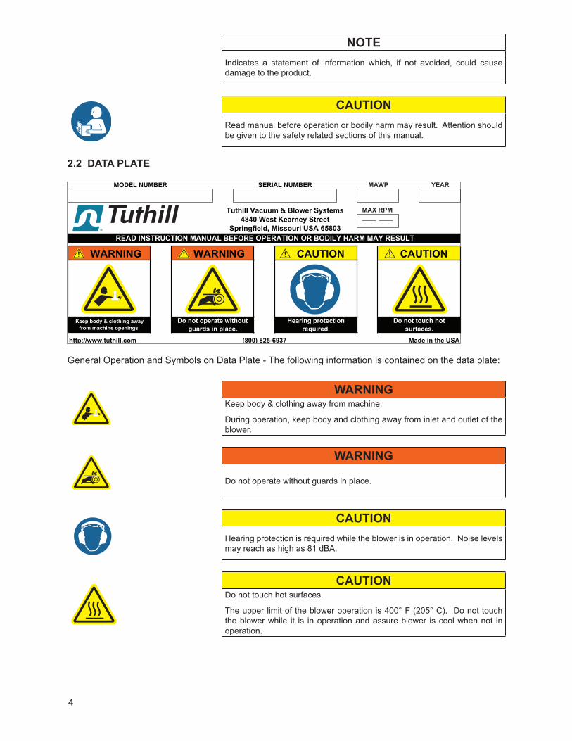
General Operation and Symbols on Data Plate - The following information is contained on the data plate:
WARNINGKeep body & clothing away from machine.
During operation, keep body and clothing away from inlet and outlet of the blower.
WARNING
Do not operate without guards in place.
CAUTIONHearing protection is required while the blower is in operation. Noise levels may reach as high as 81 dBA.
CAUTIONDo not touch hot surfaces.
The upper limit of the blower operation is 400° F (205° C). Do not touch the blower while it is in operation and assure blower is cool when not in operation.
5
MODEL NUMBER: This identifies the specific model of the blower.SERIAL NUMBER: Each blower has a unique serial number. This number is to be used with any
service issues and with any contact with the manufacturer.YEAR: This states the year that the blower was manufactured.MAWP: This states the maximum allowable working pressure (MAWP) of the blower casing.
This is NOT the allowable maximum pressure differential. When determining the pressure differential, the inlet pressure shall be taken into account to assure that the MAWP is not exceeded.
The standard MAWP is per Table 2. The MAWP shall not be exceeded unless specific factory testing of the pressure containing components of the blower has been performed.
Contact the factory for testing and documentation if this pressure is to be exceeded.
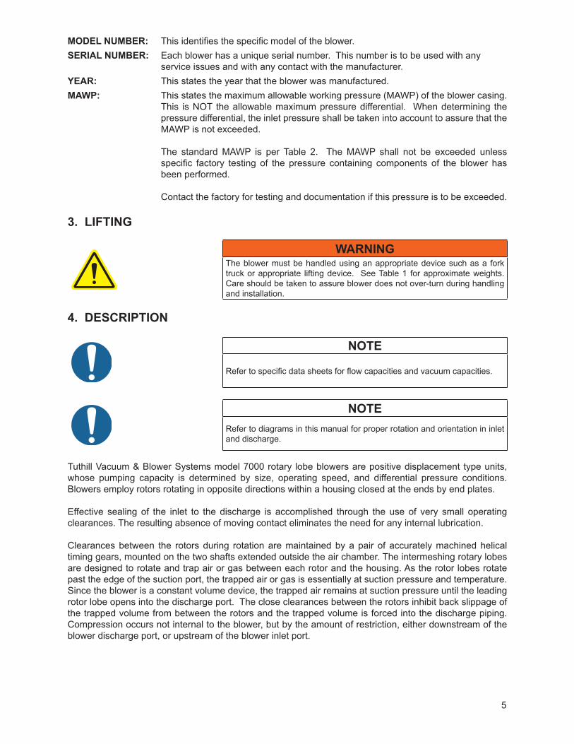
3. LIFTING
WARNINGThe blower must be handled using an appropriate device such as a fork truck or appropriate lifting device. See Table 1 for approximate weights. Care should be taken to assure blower does not over-turn during handling and installation.
4. DESCRIPTION
NOTE
Refer to specific data sheets for flow capacities and vacuum capacities.
NOTERefer to diagrams in this manual for proper rotation and orientation in inlet and discharge.
Tuthill Vacuum & Blower Systems model 7000 rotary lobe blowers are positive displacement type units, whose pumping capacity is determined by size, operating speed, and differential pressure conditions. Blowers employ rotors rotating in opposite directions within a housing closed at the ends by end plates.
Effective sealing of the inlet to the discharge is accomplished through the use of very small operating clearances. The resulting absence of moving contact eliminates the need for any internal lubrication.
Clearances between the rotors during rotation are maintained by a pair of accurately machined helical timing gears, mounted on the two shafts extended outside the air chamber. The intermeshing rotary lobes are designed to rotate and trap air or gas between each rotor and the housing. As the rotor lobes rotate past the edge of the suction port, the trapped air or gas is essentially at suction pressure and temperature. Since the blower is a constant volume device, the trapped air remains at suction pressure until the leading rotor lobe opens into the discharge port. The close clearances between the rotors inhibit back slippage of the trapped volume from between the rotors and the trapped volume is forced into the discharge piping. Compression occurs not internal to the blower, but by the amount of restriction, either downstream of the blower discharge port, or upstream of the blower inlet port.
6
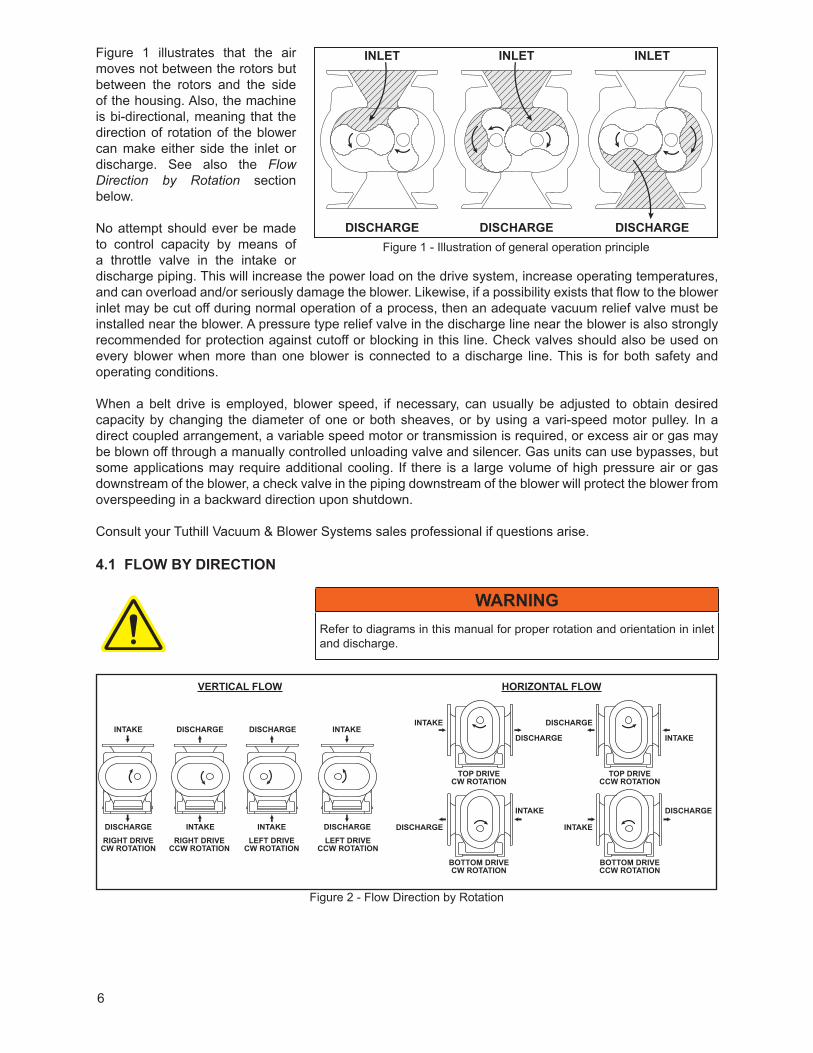
Figure 1 illustrates that the air moves not between the rotors but between the rotors and the side of the housing. Also, the machine is bi-directional, meaning that the direction of rotation of the blower can make either side the inlet or discharge. See also the Flow Direction by Rotation section below.
No attempt should ever be made to control capacity by means of a throttle valve in the intake or discharge piping. This will increase the power load on the drive system, increase operating temperatures, and can overload and/or seriously damage the blower. Likewise, if a possibility exists that flow to the blower inlet may be cut off during normal operation of a process, then an adequate vacuum relief valve must be installed near the blower. A pressure type relief valve in the discharge line near the blower is also strongly recommended for protection against cutoff or blocking in this line. Check valves should also be used on every blower when more than one blower is connected to a discharge line. This is for both safety and operating conditions.
When a belt drive is employed, blower speed, if necessary, can usually be adjusted to obtain desired capacity by changing the diameter of one or both sheaves, or by using a vari-speed motor pulley. In a direct coupled arrangement, a variable speed motor or transmission is required, or excess air or gas may be blown off through a manually controlled unloading valve and silencer. Gas units can use bypasses, but some applications may require additional cooling. If there is a large volume of high pressure air or gas downstream of the blower, a check valve in the piping downstream of the blower will protect the blower from overspeeding in a backward direction upon shutdown.
Consult your Tuthill Vacuum & Blower Systems sales professional if questions arise.
4.1 FLOW BY DIRECTION
WARNINGRefer to diagrams in this manual for proper rotation and orientation in inlet and discharge.
Figure 2 - Flow Direction by Rotation
INTAKEINTAKE
DISCHARGE INTAKE
DISCHARGE
HORIZONTAL FLOWVERTICAL FLOW
DISCHARGE
INTAKE DISCHARGE
INTAKE
DISCHARGERIGHT DRIVE
CW ROTATIONLEFT DRIVE
CW ROTATIONLEFT DRIVE
CCW ROTATIONRIGHT DRIVE
CCW ROTATION
TOP DRIVECW ROTATION
TOP DRIVECCW ROTATION
BOTTOM DRIVECW ROTATION
BOTTOM DRIVECCW ROTATION
DISCHARGEINTAKE INTAKE
INTAKEDISCHARGE DISCHARGE
Figure 1 - Illustration of general operation principle
INLET INLET INLET
DISCHARGE DISCHARGE DISCHARGE
7
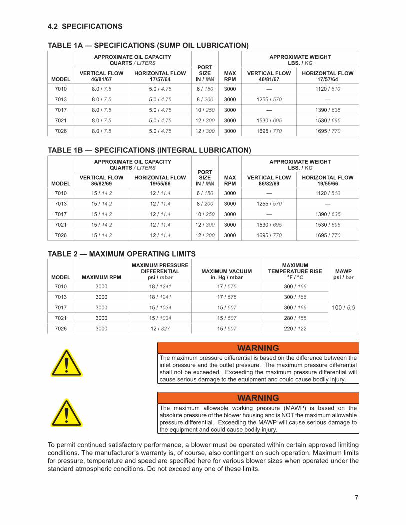
4.2 SPECIFICATIONS
TABLE 1A — SPECIFICATIONS (SUMP OIL LUBRICATION)
MODEL
APPROxIMATE OIL CAPACITYQUARTS / LITERS
PORTSIzE
IN / mmMAxRPM
APPROxIMATE WEIGHTLBS. / kg
VERTICAL FLOW46/81/67
HORIzONTAL FLOW17/57/64
VERTICAL FLOW46/81/67
HORIzONTAL FLOW17/57/64
7010 8.0 / 7.5 5.0 / 4.75 6 / 150 3000 — 1120 / 510
7013 8.0 / 7.5 5.0 / 4.75 8 / 200 3000 1255 / 570 —
7017 8.0 / 7.5 5.0 / 4.75 10 / 250 3000 — 1390 / 635
7021 8.0 / 7.5 5.0 / 4.75 12 / 300 3000 1530 / 695 1530 / 695
7026 8.0 / 7.5 5.0 / 4.75 12 / 300 3000 1695 / 770 1695 / 770
TABLE 1B — SPECIFICATIONS (INTEGRAL LUBRICATION)
MODEL
APPROxIMATE OIL CAPACITYQUARTS / LITERS
PORTSIzE
IN / mmMAxRPM
APPROxIMATE WEIGHTLBS. / kg
VERTICAL FLOW86/82/69
HORIzONTAL FLOW19/55/66
VERTICAL FLOW86/82/69
HORIzONTAL FLOW19/55/66
7010 15 / 14.2 12 / 11.4 6 / 150 3000 — 1120 / 510
7013 15 / 14.2 12 / 11.4 8 / 200 3000 1255 / 570 —
7017 15 / 14.2 12 / 11.4 10 / 250 3000 — 1390 / 635
7021 15 / 14.2 12 / 11.4 12 / 300 3000 1530 / 695 1530 / 695
7026 15 / 14.2 12 / 11.4 12 / 300 3000 1695 / 770 1695 / 770
TABLE 2 — MAxIMUM OPERATING LIMITS
MODEL MAxIMUM RPM
MAxIMUM PRESSUREDIFFERENTIAL
psi / mbarMAxIMUM VACUUM
in. Hg / mbar
MAxIMUM TEMPERATURE RISE
°F / °CMAWP
psi / bar7010 3000 18 / 1241 17 / 575 300 / 166
100 / 6.9
7013 3000 18 / 1241 17 / 575 300 / 166
7017 3000 15 / 1034 15 / 507 300 / 166
7021 3000 15 / 1034 15 / 507 280 / 155
7026 3000 12 / 827 15 / 507 220 / 122
WARNINGThe maximum pressure differential is based on the difference between the inlet pressure and the outlet pressure. The maximum pressure differential shall not be exceeded. Exceeding the maximum pressure differential will cause serious damage to the equipment and could cause bodily injury.
WARNINGThe maximum allowable working pressure (MAWP) is based on the absolute pressure of the blower housing and is NOT the maximum allowable pressure differential. Exceeding the MAWP will cause serious damage to the equipment and could cause bodily injury.
To permit continued satisfactory performance, a blower must be operated within certain approved limiting conditions. The manufacturer’s warranty is, of course, also contingent on such operation. Maximum limits for pressure, temperature and speed are specified here for various blower sizes when operated under the standard atmospheric conditions. Do not exceed any one of these limits.
8
NOTESpecially ordered blowers with nonstandard construction, or with rotor end clearances greater than shown within the Assembly Clearances table, will not have the operating limits specified here. Contact your Tuthill Vacuum & Blower Systems sales representative for specific information.
NOTESpecial attention must be paid when a blower has a higher than standard ambient suction temperature. Special recommendations for operating parameters and/or additional cooling may be recommended. Consult the factory or local representative for appropriate information.
5. INSTALLATION
5.1 GENERAL
DANGERThe blower is not intended to be used with explosive products or in explosive environments.
DANGERIt is the responsibility of the installer to assure that proper guarding is in place and compliant with all applicable regulatory requirements.
WARNINGThe bare shaft blower can generate excessive noise. Methods to reduce the noise levels by installing inlet and outlet silencers will be required. Even with inlet and outlet silencers, hearing protection will be required.
WARNINGCustomers are warned to provide adequate protection, warning and safety equipment necessary to protect personnel against hazards in the installation and operation of this equipment in the system or facility.
WARNINGThe standard MAWP is per Table 2. The MAWP shall not be exceeded unless specific factory testing of the pressure containing components of the blower has been performed.
WARNINGTable 2 states the maximum operating speed in RPM (rotations per minute)and maximum temperature. Do not exceed these limits. The installation of the blower shall take these critical operating parameters into account and adequate control features implemented.
WARNINGUpon completion of the installation, and before applying power, rotate the drive shaft by hand. It must move freely. If it does not, look for uneven mounting, piping strain, excessive belt tension or coupling misalignment or any other cause of binding. If blower is removed and still does not move freely, check inside the blower housing for foreign material.
9
NOTE
Remove the protective covers from the shaft and inspect for damage.
Carefully check to ensure that no transit damage has been sustained. If damage has occurred from shipment a claim must be filed with the carrier immediately; preserve the shipping container for inspection by the carrier.
NOTE
In the event that your unit sustains damage while being shipped to your facility, do not return it to the factory without first obtaining shipping instructions from us.
Protective covers and plugs should not be removed until the connection is being made. Mount the blower on a flat, level surface. We recommend a baseplate that is a rigid, solidly supported, and structurally sound. Shim under the legs where necessary so that each leg of the blower supports an equal share of the blower weight. This is necessary to prevent eventual twisting of the blower. Make sure feet rest evenly on the mounting surface before fastening down. Twisting or cramping the blower in mounting will cause rotor contact and binding during operation, resulting in a condition called “soft foot”. (See the Soft Foot section of this manual for further details and preventative measures.)
A unit that is factory mounted on a base, should not require the above adjustments. However, since the assembly can become twisted in shipping or installation, checking for soft foot should be done after installation of the base. Shims may be needed for alignment. Loosen the foot hold-down screws to check foot contact with the mounting surface. The base should be mounted on a solid foundation or heavy flooring, using shims as necessary at bolting points to prevent warping the assembly. (Also refer to the Foundation section.) Transmission of small operating vibrations to a support structure may be objectionable in some cases. Use of vibration isolators or vibration absorbing materials can be effective in overcoming this problem. To avoid casing distortion, the treatment used should be applied under the common motor/blower base or mounting plate, rather than directly under the feet alone.
Piping should be accurately squared with the blower and supported independently. Stress imparted from incorrectly aligned piping or mounting will create problems with bearing and seal life, possibly leading to premature internal contact. The blower should sit stress free and evenly on its supporting surface. Care should be taken to evenly tighten the mounting bolts to not impart undue stress into the blower. Stress can be checked in a free state with feeler stock or verified on a previously installed blower with the aid of a dial indicator. Less than .002” (.05 mm) spring or gap should be found.
Use only clean new pipe and make certain it is free of scale, cuttings, weld beads, dirt, or any other foreign material. To guard against damage to the blower, insure that an inlet filter is used. Make provisions to clean the filter of collected debris after a few hours of operation and periodically thereafter. (See the Piping Connections section for additional details.)
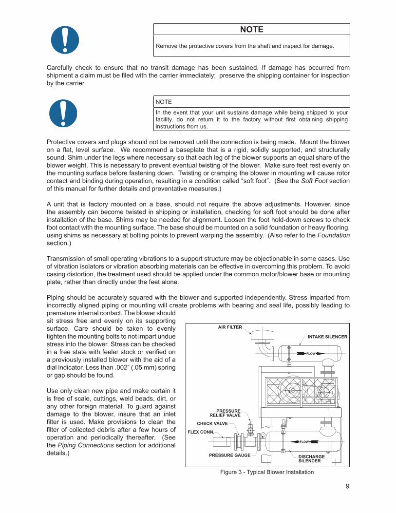
Figure 3 - Typical Blower Installation
AIR FILTER
PRESSURERELIEF VALVE
CHECK VALVE
FLEX CONN.
PRESSURE GAUGE DISCHARGESILENCER
INTAKE SILENCER
FLOW
FLOW
10
Figure 3 shows a typical complete installation of blower and accessories. Note the absence of throttle or shut-off valves in either discharge or intake piping. If it is possible for air flow to be cut off in either of these lines, make provisions to add a pressure and/or vacuum relief valve. In some installations, it may be desirable to use only an inlet silencer-cleaner supported directly from the blower connection. Weight of accessories and piping must be kept to a minimum to prevent blower casing distortion. Weights in excess of 10% of blower weight should be supported independently of blower and connected with a flexible hose or connectors. (The approximate weight of your unit is included within the Specifications table.)
A blower may be driven by direct-coupling to the driver or by V-belt drive, to obtain other speeds within approved range. (See the Motor Drives section for more information.)
Blowers from Tuthill Vacuum & Blower Systems are internally and externally treated after factory assembly and testing to protect against rusting in normal atmospheric conditions prior to installation. The maximum period of internal protection is considered to be up to 6 months under average conditions, provided closing plugs and seals are not removed. Protection against chemical or salt water atmosphere is not provided. Avoid opening the blower until ready to begin installation, as protection will be quickly lost due to evaporation. (For recommended preparations for long term storage (longer than 6 months), please see the Long Term Storage section in this manual.)
5.1.1 LOCATION
Install your blower in a room or outdoor area that supplies adequate space and lighting for routine maintenance. Indoor installation areas should be well ventilated and kept as cool as possible, because operating the unit at elevated temperatures can result in nuisance overload or temperature shutdowns. An unprotected outdoor installation is only satisfactory when correct lubrication for expected temperatures is provided, as per the Recommended Lubricants section in this manual.
5.1.2 FOUNDATION
Your blower does not need a special foundation, however it does require a solid, level floor and adequate frame support. Bolt the blower system to the floor and seal any cracks.
5.1.3 BLOWER AIR INTAKE
To minimize maintenance, supply your blower with the cleanest air possible. It is important that the air does not contain any flammable or toxic gases, as the blower will concentrate these gases. This could result in damage to the unit and surrounding property, lead to personal injury or death. Do not block or restrict the opening or the blower and/or motor may overheat and fail.
Do not use blowers on explosive or hazardous gases. Each size blower has limits on pressure differential, running speed, and discharge temperature. These limits must not be exceeded. Consult Table 2 for details pertaining to the allowable performance criteria.
If it is necessary to take air from a remote source, such as in a vacuum application, the piping should be at least the same diameter of the blower inlet. For distances greater than 20 feet (6 m) the pipe diameter should be enlarged to reduce inlet restriction. Excessive restriction will reduce the efficiency of the blower and elevate its discharge temperature. The piping used should also be corrosion resistant, and free of scale and dirt. The inlet should be covered to keep out precipitation, insects, and small animals. Vacuum kits are available.
11
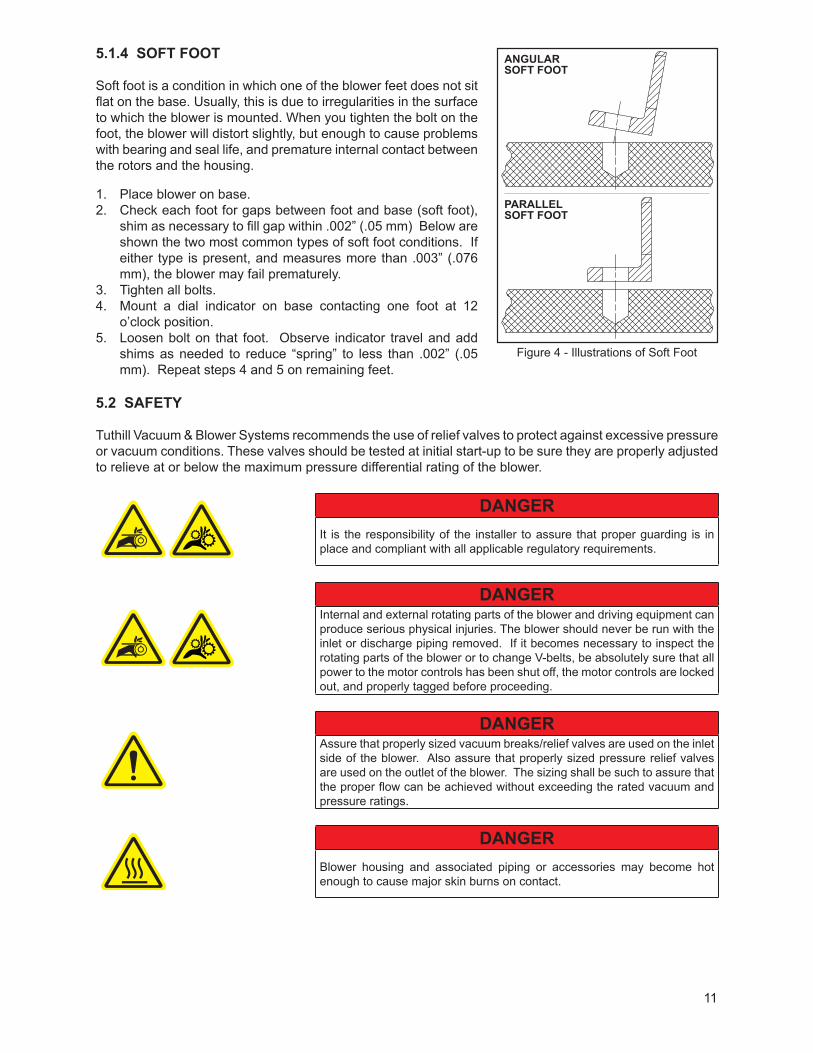
5.1.4 SOFT FOOT
Soft foot is a condition in which one of the blower feet does not sit flat on the base. Usually, this is due to irregularities in the surface to which the blower is mounted. When you tighten the bolt on the foot, the blower will distort slightly, but enough to cause problems with bearing and seal life, and premature internal contact between the rotors and the housing.
1. Place blower on base.2. Check each foot for gaps between foot and base (soft foot),
shim as necessary to fill gap within .002” (.05 mm) Below are shown the two most common types of soft foot conditions. If either type is present, and measures more than .003” (.076 mm), the blower may fail prematurely.
3. Tighten all bolts.4. Mount a dial indicator on base contacting one foot at 12
o’clock position.5. Loosen bolt on that foot. Observe indicator travel and add
shims as needed to reduce “spring” to less than .002” (.05 mm). Repeat steps 4 and 5 on remaining feet.
5.2 SAFETY
Tuthill Vacuum & Blower Systems recommends the use of relief valves to protect against excessive pressure or vacuum conditions. These valves should be tested at initial start-up to be sure they are properly adjusted to relieve at or below the maximum pressure differential rating of the blower.
DANGERIt is the responsibility of the installer to assure that proper guarding is in place and compliant with all applicable regulatory requirements.
DANGERInternal and external rotating parts of the blower and driving equipment can produce serious physical injuries. The blower should never be run with the inlet or discharge piping removed. If it becomes necessary to inspect the rotating parts of the blower or to change V-belts, be absolutely sure that all power to the motor controls has been shut off, the motor controls are locked out, and properly tagged before proceeding.
DANGERAssure that properly sized vacuum breaks/relief valves are used on the inlet side of the blower. Also assure that properly sized pressure relief valves are used on the outlet of the blower. The sizing shall be such to assure that the proper flow can be achieved without exceeding the rated vacuum and pressure ratings.
DANGERBlower housing and associated piping or accessories may become hot enough to cause major skin burns on contact.
Figure 4 - Illustrations of Soft Foot
ANGULARSOFT FOOT
PARALLELSOFT FOOT
12
WARNINGUse lock out/tag out procedures to disable the electrical energy source before any service or work is done on the blower.
WARNINGAvoid extended exposure in close proximity to machinery with high intensity noise levels. Wear adequate ear protection.
NOTEUse proper care and good procedures in handling, lifting, installing, operating, and maintaining the equipment.
5.3 LUBRICATION
Every booster from Tuthill Vacuum & Blower Systems is factory tested, oil drained and shipped dry to its installation point. Both independent oil reservoirs must be filled to the proper level before operation. Oil reservoirs are under vacuum.
Shaft bearings at the gear end of the booster are splash lubricated by one or both gears dipping into an oil reservoir formed in the gear end plate and cover. Shaft bearings at the drive end of the booster are lubricated by a slinger assembly dipping into an oil reservoir. Before starting the booster, fill oil sumps as shown below within the Filling Procedure section.
Add oil to the booster in the quantity shown within the Specifications Table. The oil level must be maintained within the notched area of the sight glass. See Figure 5 and Figure 6. Lower drive units have “bull’s eye” type oil level gauges. Maintain oil levels at the center of the glass.
WARNINGNever attempt to change or add lubrication while the booster is running. Failure to heed this warning could result in damage to the equipment or personal injury. Oil must be checked when the booster is NOT running.
WARNINGProperly dispose of the spent lubricants. Refer to the manufacturer of the lubricant and any regulations to assure proper and safe disposal.
WARNINGDo not start the booster until you are sure oil has been put in the gear housing and rear cover. Operation of the booster without proper lubrication will cause the booster to fail and void the warranty.
NOTEAssure oil is compatible with copper/yellow metals (if equipped with cooling coils).
13
NOTE
Refer to Table 1 for oil capacities.
5.3.1 FILLING PROCEDURE
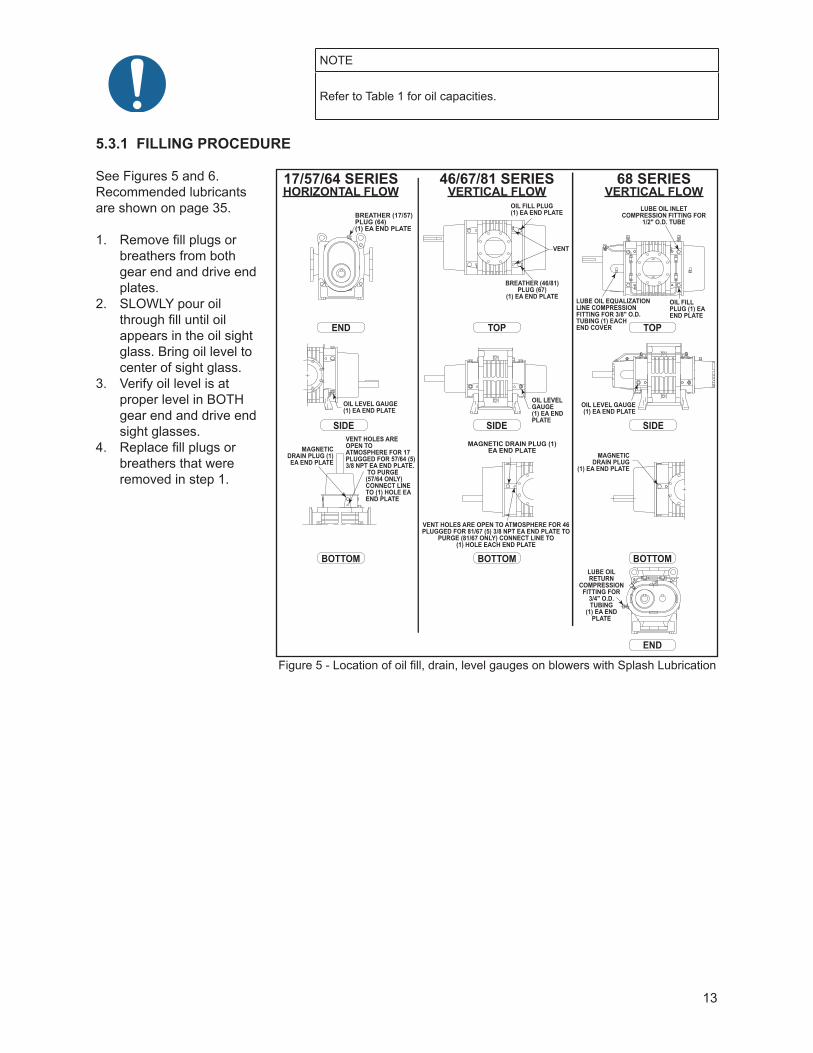
See Figures 5 and 6. Recommended lubricants are shown on page 35.
1. Remove fill plugs or breathers from both gear end and drive end plates.
2. SLOWLY pour oil through fill until oil appears in the oil sight glass. Bring oil level to center of sight glass.
3. Verify oil level is at proper level in BOTH gear end and drive end sight glasses.
4. Replace fill plugs or breathers that were removed in step 1.
Figure 5 - Location of oil fill, drain, level gauges on blowers with Splash Lubrication
SIDE
TOP TOP
SIDE SIDE
END
BOTTOM BOTTOM BOTTOM
END
17/57/64 SERIESHORIZONTAL FLOW
46/67/81 SERIESVERTICAL FLOW
68 SERIESVERTICAL FLOW
SPLASH LUBRICATION
OIL LEVEL GAUGE(1) EA END PLATE
BREATHER (17/57) PLUG (64) (1) EA END PLATE
MAGNETIC DRAIN PLUG (1) EA END PLATE
MAGNETIC DRAIN PLUG (1) EA END PLATE
MAGNETIC DRAIN PLUG
(1) EA END PLATE
VENT HOLES ARE OPEN TO ATMOSPHERE FOR 17 PLUGGED FOR 57/64 (5) 3/8 NPT EA END PLATE. TO PURGE (57/64 ONLY) CONNECT LINE TO (1) HOLE EA END PLATE
OIL FILL PLUG(1) EA END PLATE
VENT
OIL LEVEL GAUGE(1) EA END PLATE
VENT HOLES ARE OPEN TO ATMOSPHERE FOR 46 PLUGGED FOR 81/67 (5) 3/8 NPT EA END PLATE TO
PURGE (81/67 ONLY) CONNECT LINE TO(1) HOLE EACH END PLATE
BREATHER (46/81) PLUG (67)
(1) EA END PLATE
LUBE OIL RETURN
COMPRESSION FITTING FOR
3/4" O.D. TUBING
(1) EA END PLATE
OIL LEVEL GAUGE(1) EA END PLATE
OIL FILL PLUG (1) EA END PLATE
LUBE OIL INLET COMPRESSION FITTING FOR
1/2" O.D. TUBE
LUBE OIL EQUALIZATION LINE COMPRESSION FITTING FOR 3/8" O.D. TUBING (1) EACHEND COVER
14
5.3.2 FREQUENTLY ASKED QUESTIONS REGARDING LUBRICATION
What is the functional detriment if the “wrong oil” is used?The lubricant is selected based on bearing and gear speed, and operating temperature. Too light of a lubricant increases wear by not separating the sliding surfaces and it will not remove the heat adequately. If the lubricant is too thick, the drag in the bearings is increased causing them to run hotter. Since it is thicker, it will not flow as readily into the gears and it will reduce the available backlash. Lubricants at our conditions are incompressible.
What is the functional detriment if the oil is not serviced?If the lubricant is not serviced at the proper interval the shearing action in the bearing and the gears will begin to take their toll and the lubricant will thicken, making matters worse. The unit will run hotter and the wear on running surfaces will increase. Generally, the lubricant will appear dirtier, this is actually material rubbed off the unit’s components. The discoloration comes from overheating the additive package. An indicator of the breakdown of a lubricant is the increase in the TAN (Total Acid Number), and a change in the base viscosity of ten percent.
Several things are happening as the lubricant goes through the unit. First, it is absorbing frictional energy in the form of heat. This heat has to be dissipated through either surface contact with cooler materials, or in a rest volume of lubricant. While reducing the friction, the lubricant is also going through a shearing process and the molecular structure is broken down.
The result is that the lubricant will begin to thicken because of the shorter molecular chains and the drop out of additive packages. The thickened lubricant will cause more drag, increasing the friction and heat, and further degrading the lubricant.
Operation of the booster (environment, run time, speed, and pressure) has a direct effect on duty cycles. Our published cycles are based on worst-case conditions.
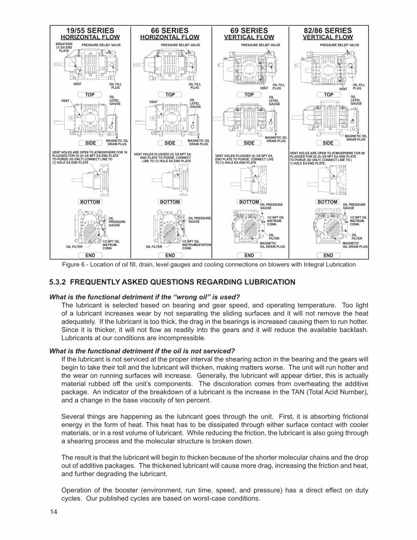
Figure 6 - Location of oil fill, drain, level gauges and cooling connections on blowers with Integral Lubrication
SIDE SIDE SIDE SIDE
TOP TOP TOP TOP
END END END END
BOTTOM BOTTOM BOTTOM BOTTOM
19/55 SERIESHORIZONTAL FLOW
66 SERIESHORIZONTAL FLOW
69 SERIESVERTICAL FLOW
82/86 SERIESVERTICAL FLOW
INTEGRAL LUBRICATION
BREATHER(1) EA END
PLATEPRESSURE RELIEF VALVE PRESSURE RELIEF VALVE PRESSURE RELIEF VALVE PRESSURE RELIEF VALVE
VENT HOLES PLUGGED (5) 3/8 NPT EA END PLATE TO PURGE, CONNECT
LINE TO (1) HOLE EA END PLATE
VENT
VENT
MAGNETIC OILDRAIN PLUG
MAGNETIC OILDRAIN PLUG
MAGNETIC OILDRAIN PLUG
MAGNETIC OILDRAIN PLUG
OILLEVELGAUGE
OILLEVELGAUGE
OILLEVELGAUGE
OILLEVELGAUGE
VENT HOLES PLUGGED (5) 3/8 NPT EA END PLATE TO PURGE, CONNECT LIVE TO (1) HOLE EA END PLATE
VENT HOLES ARE OPEN TO ATMOSPHERE FOR 86PLUGGED FOR 82 (5) 3/8 NPT EA END PLATETO PURGE (82 ONLY) CONNECT LINE TO (1) HOLE EA END PLATE.
MAGNETICOIL DRAIN PLUG
OIL PRESSUREGAUGE
OIL FILTER
1/2 NPT OIL INSTRUM.CONN.
MAGNETICOIL DRAIN PLUG
OIL PRESSUREGAUGE
OIL FILTER
1/2 NPT OIL INSTRUM.CONN.
OIL FILL PLUG
OIL FILL PLUG
OIL FILL PLUG VENT
OIL FILL PLUG
OIL FILTER1/2 NPT OILINSTRUM.CONN
OIL PRESSURE GAUGE
OILPRESSURE GAUGE
OIL FILTER1/2 NPT OILINSTRUMENTATIONCONN
VENT
VENT
VENT HOLES ARE OPEN TO ATMOSPHERE FOR 19PLUGGED FOR 55 (5) 3/8 NPT EA END PLATETO PURGE (55 ONLY) CONNECT LINE TO(1) HOLE EA END PLATE
15
5.3.3 HAzARDS ASSOCIATED WITH BREAKDOWN OR IGNITION OF LUBRICATION
DANGERThere is a risk associated with the lubrication media breaking down and resulting in a hazardous fluid or vapor. There may also be a hazard associated with the ignition of the lubrication media. Refer to the lubrication manufacture’s applicable instruction for safety precautions.
5.3.4 LUBRICATION (SPLASH - 90/91 SERIES)
WARNINGFor connecting water, remove only the 1” NPT plugs with the 5/8” allen heads. Use of any other connection for water will cause serious damage to unit.
Before starting the unit, fill oil reservoirs as instructed below:1. Remove fill plugs or breathers from gear (drive) end and free (non-drive) end plates.2. Pour oil through fill hole until oil appears in sight glass. Slowly bring oil up to center of glass. Repeat for
both end plates. Each oil sump must be filled independently. 3. Re-seal plugs and reinstall in end plates.4. Oil levels should be checked frequently. Unit must be shut down to properly check oil levels.
5.3.5 LUBRICATION (INTEGRAL PRESSURE - 31/33 SERIES)
1. Before starting the unit, fill reservoirs as instructed below:2. Remove oil fill plug.3. Pour oil through fill hole until oil appears in sight glass. 4. The front and back oil reservoirs are connected together; however, it will take some time for the oil to
travel to the front of the machine. Allow several minutes for this to occur.5. Bring oil level up to the center of the sight glass. Again, allow time for equalization of oil level between
the back and the front of the machine.6. Reinstall fill plug.
5.3.6 OIL FILTER
Change the oil filter element with every oil change. Filters (P/N 70248) are available from Tuthill Vacuum and Blower Systems in Springfield, Missouri, or from any authorized distributor or service center.
16
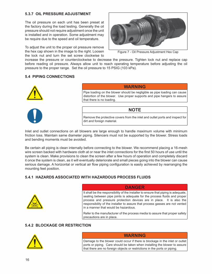
5.3.7 OIL PRESSURE ADJUSTMENT
The oil pressure on each unit has been preset at the factory during the load testing. Generally the oil pressure should not require adjustment once the unit is installed and in operation. Some adjustment may be require due to the speed and oil temperature.
To adjust the unit to the proper oil pressure remove the hex cap shown in the image to the right. Loosen the lock nut and turn the set screw clockwise to increase the pressure or counterclockwise to decrease the pressure. Tighten lock nut and replace cap before reading oil pressure. Always allow unit to reach operating temperature before adjusting the oil pressure to the proper range. Set the oil pressure to 15 PSIG (103 kPa).
5.4 PIPING CONNECTIONS
WARNINGPipe loading on the blower should be negligible as pipe loading can cause distortion of the blower. Use proper supports and pipe hangers to assure that there is no loading.
NOTERemove the protective covers from the inlet and outlet ports and inspect for dirt and foreign material.
Inlet and outlet connections on all blowers are large enough to handle maximum volume with minimum friction loss. Maintain same diameter piping. Silencers must not be supported by the blower. Stress loads and bending moments must be avoided.
Be certain all piping is clean internally before connecting to the blower. We recommend placing a 16-mesh wire screen backed with hardware cloth at or near the inlet connections for the first 50 hours of use until the system is clean. Make provisions to clean the screen after a few hours of operation and completely discard it once the system is clean, as it will eventually deteriorate and small pieces going into the blower can cause serious damage. A horizontal or vertical air flow piping configuration is easily achieved by rearranging the mounting feet position.
5.4.1 HAzARDS ASSOCIATED WITH HAzARDOUS PROCESS FLUIDS
DANGERIt shall be the responsibility of the installer to ensure that piping is adequate, sealing between pipe joints is adequate for the process fluids and proper process and pressure protection devices are in place. It is also the responsibility of the installer to assure that process gasses are not vented in a manner that would be hazardous.
Refer to the manufacturer of the process media to assure that proper safety precautions are in place.
5.4.2 BLOCKAGE OR RESTRICTION
WARNINGDamage to the blower could occur if there is blockage in the inlet or outlet ports or piping. Care should be taken when installing the blower to assure that there are no foreign objects or restrictions in the ports or piping.
Figure 7 - Oil Pressure Adjustment Hex Cap
17
5.4.3 HAzARDS ASSOCIATED WITH HAzARDOUS PROCESS FLUIDS
DANGERIt shall be the responsibility of the installer to ensure that piping is adequate, sealing between pipe joints is adequate for the process fluids and proper process and pressure protection devices are in place. It is also the responsibility of the installer to assure that process gasses are not vented in a manner that would be hazardous.
Refer to the manufacturer of the process media to assure that proper safety precautions are in place.
5.4.4 BLOCKAGE OR RESTRICTION
WARNINGDamage to the blower could occur if there is blockage in the inlet or outlet ports or piping. Care should be taken when installing the blower to assure that there are no foreign objects or restrictions in the ports or piping.
5.5 COOLING COILS (OPTIONAL)
CAUTIONIf the blower is to be located outdoors or in a building where the temperature surrounding the blower or the water supply and return piping can fall below 35° F (2° C), then care must be taken to ensure that the water (or other cooling liquid) does not freeze and cause damage.Cooling coils must be drained of liquid during downtime unless a recirculating unit using a glycol mixture has been installed.
NOTEWater cooled endplates are discontinued. Consult factory for connection details.
NOTEUnits are never shipped from the manufacturer with liquid in the end plates or cooling coils.
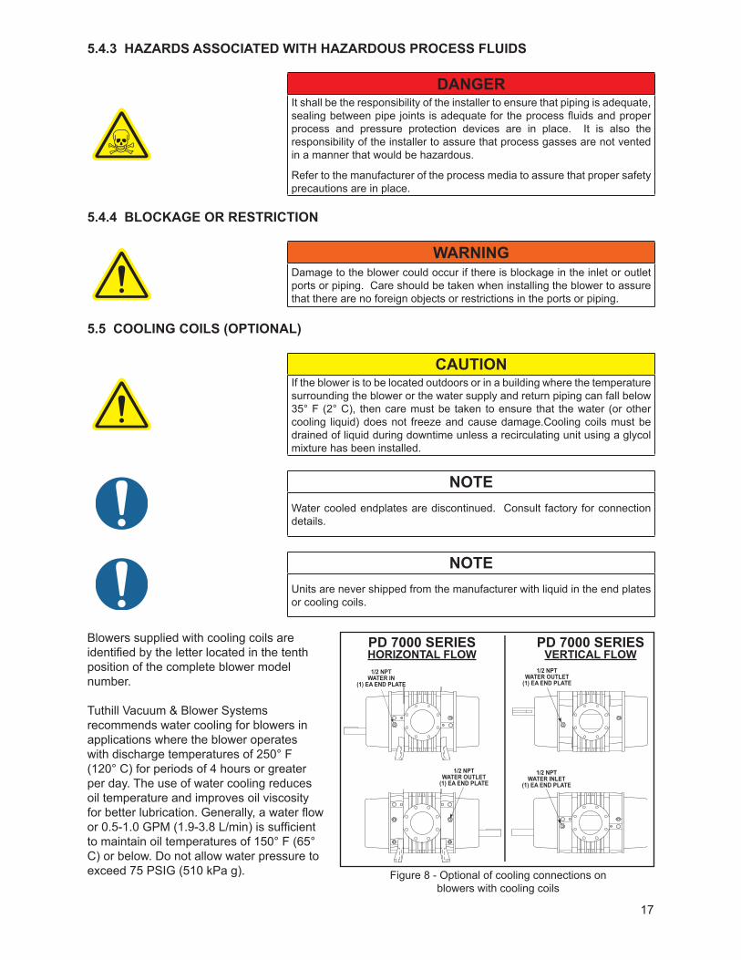
Blowers supplied with cooling coils are identified by the letter located in the tenth position of the complete blower model number.
Tuthill Vacuum & Blower Systems recommends water cooling for blowers in applications where the blower operates with discharge temperatures of 250° F (120° C) for periods of 4 hours or greater per day. The use of water cooling reduces oil temperature and improves oil viscosity for better lubrication. Generally, a water flow or 0.5-1.0 GPM (1.9-3.8 L/min) is sufficient to maintain oil temperatures of 150° F (65° C) or below. Do not allow water pressure to exceed 75 PSIG (510 kPa g). Figure 8 - Optional of cooling connections on
blowers with cooling coils
PD 7000 SERIESHORIZONTAL FLOW
PD 7000 SERIESVERTICAL FLOW
1/2 NPTWATER OUTLET
(1) EA END PLATE
1/2 NPTWATER OUTLET
(1) EA END PLATE
1/2 NPTWATER IN
(1) EA END PLATE
1/2 NPTWATER INLET
(1) EA END PLATE
18
5.6 COOLING WATER CONNECTIONS AND SPECIFICATIONS — COOLING COILS (OPTIONAL)
WARNING
The cooling water pressure shall not exceed 75 psig (5.17 bar g)
5.7 MOTOR DRIVES
Two drive connections commonly used are direct drive and V-belt drive.
5.7.1 DIRECT COUPLED
When installing the motor directly to the blower, align shafts to coupling in accordance with the coupling manufacturer’s instructions. Blowers shipped with motor directly coupled and mounted on a common base have been aligned prior to shipment and normally no further alignment is necessary. However, alignment should be checked and adjustments made if necessary prior to starting the unit.
Coupling halves must correctly fit the blower and drive shafts so that only light tapping is required to install each half. The two shafts must be accurately aligned, A direct coupled blower and motor must be aligned with the two shafts not having more than .005” (13 mm) T.I.R. (Total Indicator Reading). Face must be aligned within .002”(.05 mm) .
Proper gap between coupling halves must be established according to coupling manufacturers instructions with the motor armature. This will minimize the change for end thrust on the blower shaft. All direct coupled base mounted units must be re-aligned and greased after field installation.
5.7.2 V-BELTS
If the motor and blower are V-belt connected, the sheaves on both motor and blower shafts, should be as close to the shaft bearings as possible. Blower Sheave is not more than 1/4” (6.5 mm) from the blower drive end cover. The drive sheave is as close to the driver bearing as possible. Care should be taken when installing sheaves on the blower and motor shafts. The face of the should be accurately in line to minimize belt wear.
Adjust the belt tension to the to the manufactures specifications using a belt tension tester. New belts should be checked for proper tension after 24 hours of run time. When manufacturer data is not available industry guidelines are 1/64 inch deflection for each inch of span at 8 to 10 pounds of force in the center of the belt.
Insufficient tensioning is often indicated by slipping (squealing) at start up. Belt dressing should not be used on V-belts. Sheaves and V-belts should remain free of oil and grease. Tension should be removed from belts if the drive is to be inactive for an extended period of time. For more specific information consult the drive manufacturer. In a V-belt drive, the blower sheave must fit its shaft accurately, run true, and be mounted as close to the bearing housing as possible to minimize bearing loads.
A tight or driving fit will force the drive shaft out of its normal position and cause internal damage. A loose fit will result in shaft damage or breaking. The motor sheave must also fit correctly and be properly aligned with the blower sheave.
Adjust motor position on its sliding base so that belt tension is in accordance with drive manufacturer’s instructions. Avoid excessive belt tension at all times. Recheck tension after the first ten hours of operation and periodically thereafter to avoid slippage and loss of blower speed.
Check blower after installation and before applying power by rotating the drive shaft by hand. If it does not rotate freely, look for uneven mounting, piping strain, excessive belt tension, or coupling misalignment. Check blower at this time to insure oil was added to the reservoirs.
19
5.7.3 SETTING V-BELT TENSION
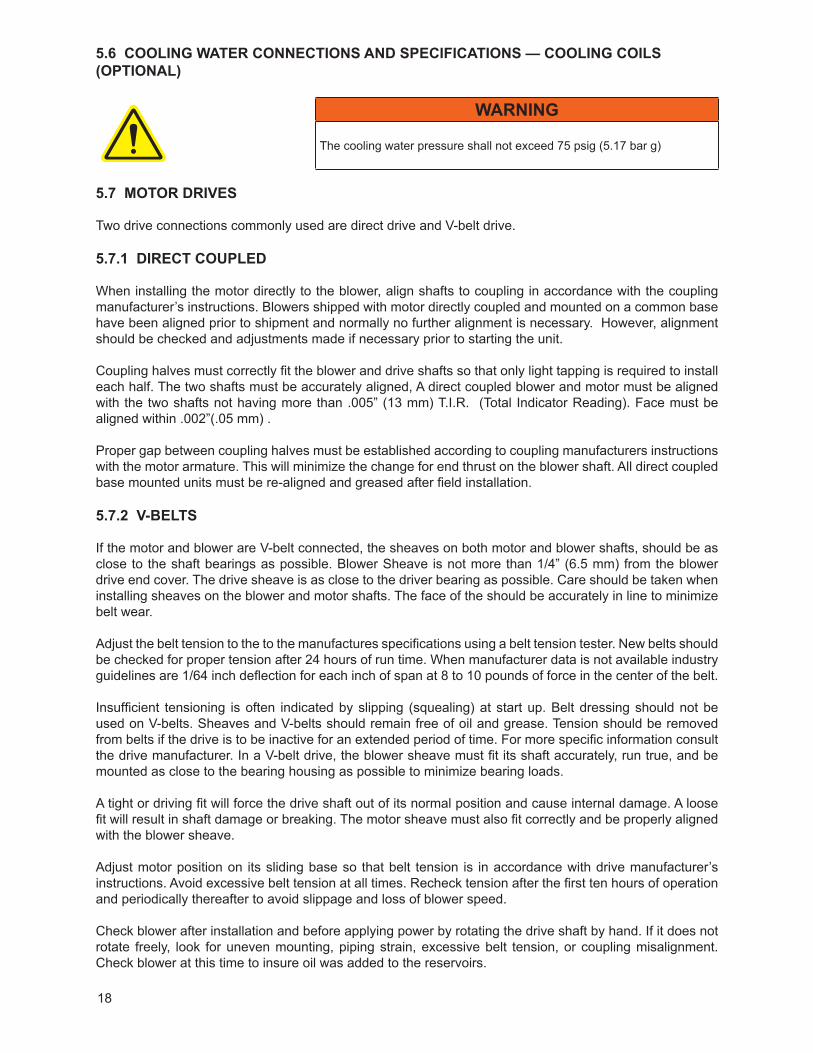
Proper belt tension is essential to long blower life. The following diagrams and procedures are provided to aid in field adjusting V-belts (when blower is so equipped) for maximum performance. A visual inspection of the V-belt drive should yield the appearance shown in Figure 9.
Factors outside the control of the belt tensioning system used on an individual blower package assembly may contribute to decreased belt life, such as environmental factors, and quality of the belts installed. This can cause wear of the belts beyond the ability of the tensioning system to compensate.
As such, it is recommended to check belt tension monthly and make any manual adjustments found necessary.
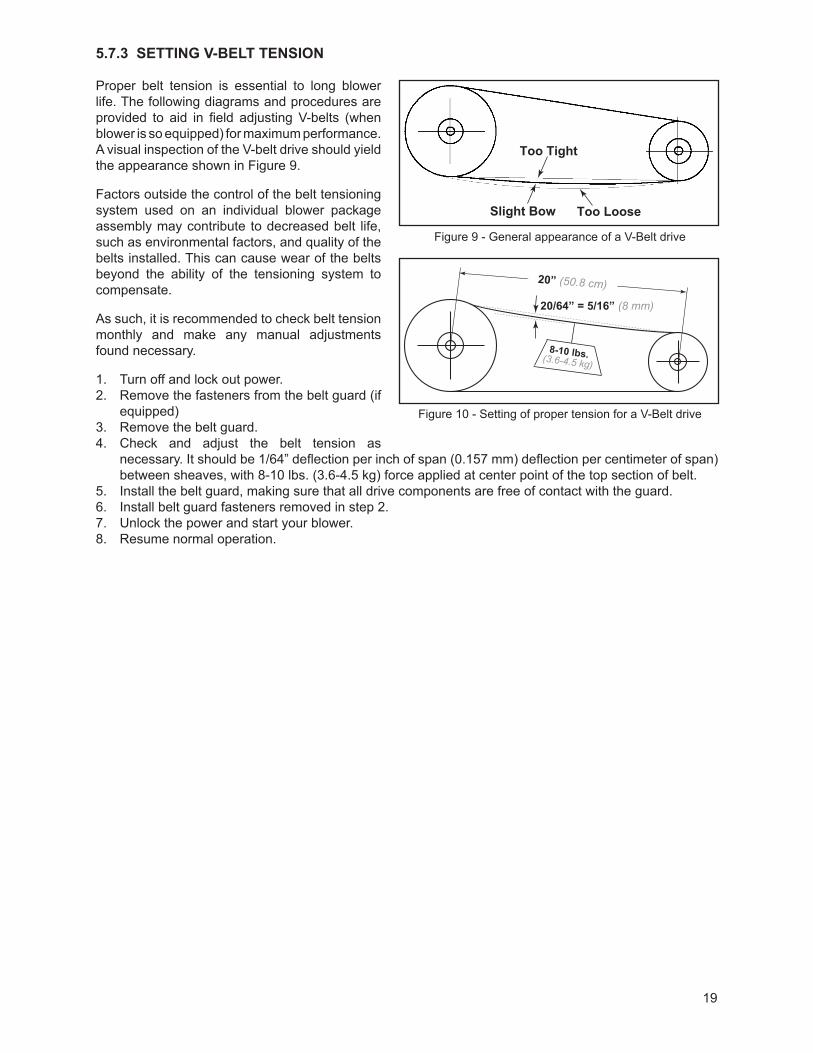
1. Turn off and lock out power. 2. Remove the fasteners from the belt guard (if
equipped)3. Remove the belt guard.4. Check and adjust the belt tension as
necessary. It should be 1/64” deflection per inch of span (0.157 mm) deflection per centimeter of span) between sheaves, with 8-10 lbs. (3.6-4.5 kg) force applied at center point of the top section of belt.
5. Install the belt guard, making sure that all drive components are free of contact with the guard.6. Install belt guard fasteners removed in step 2.7. Unlock the power and start your blower.8. Resume normal operation.
Too Tight
Slight Bow Too Loose
20/64” = 5/16” (8 mm)
20” (50.8 cm)
8-10 lbs.(3.6-4.5 kg)
Too Tight
Slight Bow Too Loose
20/64” = 5/16” (8 mm)
20” (50.8 cm)
8-10 lbs.(3.6-4.5 kg)
Figure 9 - General appearance of a V-Belt drive
Figure 10 - Setting of proper tension for a V-Belt drive
20
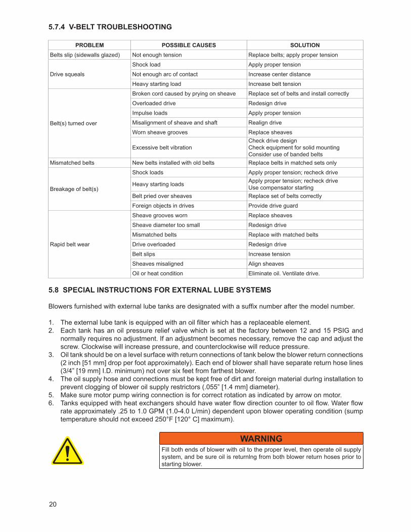
5.7.4 V-BELT TROUBLESHOOTING
PROBLEM POSSIBLE CAUSES SOLUTIONBelts slip (sidewalls glazed) Not enough tension Replace belts; apply proper tension
Drive squeals
Shock load Apply proper tension
Not enough arc of contact Increase center distance
Heavy starting load Increase belt tension
Belt(s) turned over
Broken cord caused by prying on sheave Replace set of belts and install correctly
Overloaded drive Redesign drive
Impulse loads Apply proper tension
Misalignment of sheave and shaft Realign drive
Worn sheave grooves Replace sheaves
Excessive belt vibrationCheck drive designCheck equipment for solid mountingConsider use of banded belts
Mismatched belts New belts installed with old belts Replace belts in matched sets only
Breakage of belt(s)
Shock loads Apply proper tension; recheck drive
Heavy starting loads Apply proper tension; recheck driveUse compensator starting
Belt pried over sheaves Replace set of belts correctly
Foreign objects in drives Provide drive guard
Rapid belt wear
Sheave grooves worn Replace sheaves
Sheave diameter too small Redesign drive
Mismatched belts Replace with matched belts
Drive overloaded Redesign drive
Belt slips Increase tension
Sheaves misaligned Align sheaves
Oil or heat condition Eliminate oil. Ventilate drive.
5.8 SPECIAL INSTRUCTIONS FOR ExTERNAL LUBE SYSTEMS
Blowers furnished with external lube tanks are designated with a suffix number after the model number.
1. The external lube tank is equipped with an oil filter which has a replaceable element. 2. Each tank has an oil pressure relief valve which is set at the factory between 12 and 15 PSIG and
normally requires no adjustment. If an adjustment becomes necessary, remove the cap and adjust the screw. Clockwise will increase pressure, and counterclockwise will reduce pressure.
3. Oil tank should be on a level surface with return connections of tank below the blower return connections (2 inch [51 mm] drop per foot approximately). Each end of blower shall have separate return hose lines (3/4” [19 mm] I.D. minimum) not over six feet from farthest blower.
4. The oil supply hose and connections must be kept free of dirt and foreign material durlng installation to prevent clogging of blower oil supply restrictors (.055” [1.4 mm] diameter).
5. Make sure motor pump wiring connection is for correct rotation as indicated by arrow on motor.6. Tanks equipped with heat exchangers should have water flow direction counter to oil flow. Water flow
rate approximately .25 to 1.0 GPM (1.0-4.0 L/min) dependent upon blower operating condition (sump temperature should not exceed 250°F [120° C] maximum).
WARNINGFill both ends of blower with oil to the proper level, then operate oil supply system, and be sure oil is returnlng from both blower return hoses prior to starting blower.
21
5.9 MOTOR AND ELECTRICAL CONNECTIONS
WARNINGThe motor and connections shall be protected to assure that product and environmental condensation does not come in contact with the electrical connections.
NOTEIt is the responsibility of the installer to assure that the motor is in compliance with the latest edition of IEC 60204-1 and all electrical connections performed per IEC 60204-1, this includes over current protection.
Wire the motor and other electrical devices such as solenoid valves and temperature switch to the proper voltage and amperage as indicated on the nameplate of each component being wired. Turn the blower by hand after wiring is completed to determine that there are no obstructions and if the blower turns freely; then momentarily start the blower to check the direction of rotation. Figure 2 shows direction of air flow in relation to rotor rotation. The air flow direction can be reversed by reversing the appropriate motor leads.
6. OPERATION
6.1 GENERAL
DANGERThe blower is not intended to be used with explosive products or in explosive environments.
WARNING
Do not operate without guards in place.
WARNINGMaximum operating speed: Table 2 states the maximum operating speed in RPM (rotations per minute), the maximum pressure differential, maximum vacuum and maximum temperature rise. Do not exceed these limits.
Before starting the blower for the first time under power, recheck the installation thoroughly to reduce the likelihood of troubles. Use the following check list as a guide, but also consider any other special conditions in your installation.
1. Be certain no bolts, rags, or dirt have been left in blower.2. Be certain that inlet piping is free of debris. If an open outdoor air intake is used, be sure the opening is
clean and protected by an inlet filter. This also applies to indoor use.3. If installation is not recent, check blower leveling, drive alignment, belt tension, and tightness of all
mounting bolts.4. Be certain the proper volume of oil is in the oil reservoir chambers.5. Be certain the driving motor is properly lubricated, and that it is connected through suitable electrical
overload devices.6. With electrical power off and locked out to prevent accidental starting, rotate blower shaft several times
by hand to make sure blower is rotating freely. Unevenness or tight spots is an indication of a problem that should be corrected before progressing.
7. Check motor rotation by momentarily pushing the start button and check flow direction of the blower. Reverse the motor connections if flow is in the wrong direction.
22
Initial operation should be carried out under “no load” conditions by opening all valves and venting the discharge to atmosphere, if possible. Then start motor briefly, listen for unusual noises, and check that the blower coasts freely to a stop. If no problem appears, repeat this check, and let the motor run a little longer. If any questions exist, investigate before proceeding further.
Assuming all tests are satisfactory, the blower will now be ready for continuous full load operation. During the first several days, make periodic checks to determine that all conditions remain acceptable and steady. These checks may be particularly important if the blower is part of a process system where conditions may vary. At the first opportunity, stop the blower and clean or remove inlet filter. Also, recheck leveling, coupling alignment or belt tension, and mountlng bolts for tightness.
6.2 START-UP CHECKLISTWe recommend that these startup procedures be followed in sequence and checked off ( ) in the boxes provided in any of the following cases:
• During initial installation• After any shutdown period
• After maintenance work has been performed• After blower has been moved to a new location
DATES CHECKED:
Check the unit for proper lubrication. Proper oil level cannot be over-emphasized. Refer to the Lubrication section. Please see Recommended Lubricants for information on acceptable lubricants for your product.
Check V-belt drive for proper belt alignment and tension.
Carefully turn the rotors by hand to be certain they do not bind.
WARNINGDisconnect power. Make certain power is off and locked out before touching any rotating element of the blower, motor, or drive components.
“Bump” the unit with the motor to check rotation (counter-clockwise [CCW] when facing shaft) and to be certain it turns freely and smoothly.
Start the unit and operate it for 30 minutes at no load. During this time, feel the cylinder for hot spots. If minor hot spots occur, refer to the Troubleshooting chart.
Apply the load and observe the operation of the unit for one hour.
If minor malfunctions occur, discontinue operation and refer to the Troubleshooting chart.
6.3 OPERATING
The upper temperature limit for blower operation is 400° F (205° C) measured in the exhaust gas stream with a low mass thermocouple. When this temperature limit switch is installed, as the temperature exceeds the predetermined temperature, the blower motor will stop and cannot be restarted until the temperature drops below the trip setting of the temperature switch.
DANGERThe blower is not intended to be used with explosive products or in explosive environments.
23
WARNINGPhysical harm may occur if human body parts are in contact or exposed to the process vacuum. Assure that all connections are protected from human contact.
WARNINGIf rated vacuum or pressure levels are exceeded, process fluids will migrate to other parts of the blower and system.
CAUTIONDo not touch hot surfaces.
The upper limit of the blower operation is 400° F (205° C). Do not touch the blower while it is in operation and assure blower is cool when not in operation.
CAUTIONUse of a thermowell insulates the thermocouple. Invalid and delayed readings will result. This can result in ineffective protection devices.
NOTEThe upper temperature limits are not intended for continuous operation. Consult with factory for detailed information assistance.
6.4 STOPPING
CAUTIONDo not stop the blower if there are high outlet pressures in the outlet piping. Unload the outlet piping prior to shutting down the blower.
Stop the blower by turning off the motor. Isolate the blower from the vacuum system and vent the blower to atmosphere. Turn off the cooling water, if water cooled. Stop the backing pump. Refer to component instruction manual.
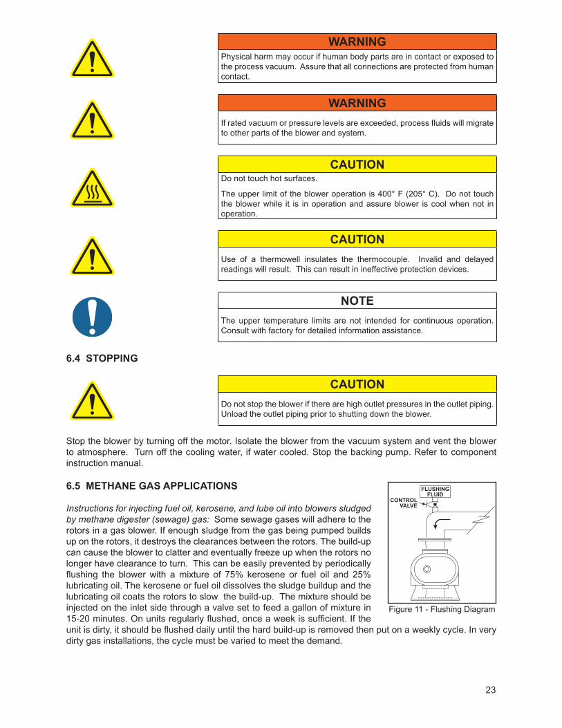
6.5 METHANE GAS APPLICATIONS
Instructions for injecting fuel oil, kerosene, and lube oil into blowers sludged by methane digester (sewage) gas: Some sewage gases will adhere to the rotors in a gas blower. If enough sludge from the gas being pumped builds up on the rotors, it destroys the clearances between the rotors. The build-up can cause the blower to clatter and eventually freeze up when the rotors no longer have clearance to turn. This can be easily prevented by periodically flushing the blower with a mixture of 75% kerosene or fuel oil and 25% lubricating oil. The kerosene or fuel oil dissolves the sludge buildup and the lubricating oil coats the rotors to slow the build-up. The mixture should be injected on the inlet side through a valve set to feed a gallon of mixture in 15-20 minutes. On units regularly flushed, once a week is sufficient. If the unit is dirty, it should be flushed daily until the hard build-up is removed then put on a weekly cycle. In very dirty gas installations, the cycle must be varied to meet the demand.
FLUSHINGFLUID
CONTROLVALVE
Figure 11 - Flushing Diagram
24
6.6 WATER INJECTED BLOWERS
Water injected into the inlet of a blower operating on vacuum service will cool the blower. The water absorbs the heat of compression as it passes through the unit along with the air/gas being compressed. A blower cooled in this manner can operate safely at higher vacuums or higher inlet temperatures than a normally uncooled unit.
The amount of water required depends on the inlet air/gas temperature, inlet vacuum, water temperature, and the maximum discharge temperature desired. Check with the factory or sales representative for additional guidance.
6.6.1 OPERATION
1. Check oil level in sight glass of blower and assure all fittings are tight.2. Check the water injection system to assure water is available.3. Operate the blower dry for a few minutes at no load to check correct rotation and smooth operation.4. Turn water on and adjust flow as recommended for the individual blower. Assure water discharges
freely from the outlet piping.5. Apply vacuum and observe operation at the desired inlet condition.
6.6.2 SHUTDOWN
1. The blower can be shutdown for brief periods by relieving the inlet vacuum, shutting the water off, and then stopping the unit.
2. Rusting during a slightly longer shutdown period can be avoided by operating the blower under a partial vacuum without the water injection, allowing the blower to heat within safe limits. The heat will tend to drive off residual moisture.
3. For extended shutdown, oil may be injected into the inlet of the heated blower just prior to shutting the blower down. The oil will provide a protective coating on the internals. Insure that the water is completely shut off after shutdown.
4. Special coatings or platings are available to minimize rusting or corrosion in applications where units can remain wet.
Vertical flow units with two-lobed, plugged rotors should always be used. Always orient system such that the blower intake is at the top and discharge at the bottom.
CAUTIONWater injection can cause lime build-up on rotors. Check water supply for hardness. The use of water softeners, other chemicals, or distilled water may be necessary to prevent or remove this build-up. However, due to the wide variations in mineral content, pH, and chemical content of water that can be injected, Tuthill Vacuum & Blower Systems cannot be responsible for damage which may result should this build-up occur. Units should be inspected regularly to determine any problems.
NOTE
For liquid injection other than water, consult the factory.
6.7 RECOMMENDED SHUTDOWN PROCEDURE TO MINIMIzE RISK OF FREEzING OR CORROSION
When high humidity or moisture is present in an air piping system, condensation of water can occur after the blower is shut down and the blower begins to cool. This creates an environment favorable to corrosion of the iron internal surfaces, or in cold weather, the formation of ice. Either of these conditions can close the operating clearances, causing the blower to fail upon future start-up.
25
The following shutdown procedure outlined below minimizes the risk of moisture condensation, corrosion and freezing.
NOTECare must be taken so as not to overload or overheat the blower during this procedure.
1. Isolate the blower from the moist system piping, allowing the blower to intake atmospheric air. Operate the blower under a slight load allowing the blower to heat within safe limits. The heat generated by the blower will quickly evaporate residual moisture.
2. For carpet cleaning applications, after the work is completed, simply allow the blower to run a few (3-5) minutes with the suction hose and wand attached. The suction hose and wand will provide enough load to the blower to evaporate the moisture quickly.
3. For extended shutdown, inject a small amount of a light lubricating oil such as 3-in-One® or a spray lubricant such as WD-40® into the inlet of the blower just prior to shutdown. (3-in-One and WD-40 are registered trademarks of WD-40 Company.) The lubricant will provide an excellent protective coating on the internal surfaces. If using a spray lubricant, exercise care to prevent the applicator tube from getting sucked into the blower. The applicator tube will damage the blower, most likely to the point that repair would be required.
4. If the blower is being taken out of commission for an extended period of time, please also refer to the “Long Term Storage” section of this manual.
7. MAINTENANCE
7.1 GENERAL
Regular inspection of your blower and its installation, along with complete checks on operating conditions will pay dividends in added life and usefulness. Also, service the drive per manufacturer’s instructions and lubricate the coupling or check belt drive tension. By use of thermometers and gauges, make sure that blower operating temperature and pressure remain within allowed limits.
DANGERThe blower and parts may contain hazardous media. Assure that pump and parts are evacuated of hazardous media prior to servicing.
CAUTIONThe electrical service must be isolated and de-energized prior to maintenance. Apply appropriate procedures to assure electrical supply is de-energized and cannot be inadvertently energized during maintenance.
Assure piping and product is isolated prior to maintenance of blower. Apply appropriate procedures to assure piping and product is isolated and that inadvertent opening of valves cannot occur during maintenance.
CAUTIONDuring routine maintenance, inspect and assure that guards are in place and secure.
Particular attention should be paid to lubrication of timing gears and bearings in accordance with comments under the Lubrication section.
When a blower is taken out of service, it may require internal protection against rusting or corrosion. The need for such protection must be a matter of judgment based on existing conditions as well as length of down time. Under atmospheric conditions producing rapid corrosion, the blower should be protected immediately. Refer to the Long Term Storage section for more details.
26
7.2 REGULAR MAINTENANCE
A good maintenance program will add years of service to your blower.
A newly installed blower should be checked frequently during the first month of operation, especially lubrication. With blower at rest, check oil level in both the gear (drive) end and free (non-drive) end of the blower and add oil as needed. Complete oil changes are recommended every 1000-1200 operating hours, or more frequently depending on the type of oil and operating temperature. Also change the oil more frequently if pumping corrosive vapors or where excessive operating temperatures are encountered. The following is recommended as a minimum maintenance program.
DAILY WEEKLY MONTHLY1. Check and maintain oil level, and add oil as necessary.
2. Check for unusual noise or vibration (See Troubleshooting)
1. Clean all air filters. A clogged air filter can seriously affect the efficiency of the blower and cause overheating and oil usage.
2. Check relief valve to assure it is operating properly.
1. Inspect the entire system for leaks.
2. Inspect condition of oil and change if necessary.
3. Check drive belt tension and tighten if necessary.
NOTE
Oil levels should be checked every 24 hours of operation.
Proper oil drain schedules require oil be changed before the contaminant load becomes so great that the lubricating function of the oil is impaired or heavy disposition of suspended contaminants occurs. To check the condition of the oil, drain a sampling into a clean container and check for the presence of water or solids. Slight discoloration of the oil should not necessitate an oil change.
7.3 SPARE PARTS
Should adjustments or replacement eventually be needed, these can often be performed locally as described in this book after obtaining required parts. Personnel should have a good background of mechanical experience and be thoroughly familiar with the procedures outlined in this manual. Major repairs not covered in this book should be referred to the nearest Tuthill Vacuum & Blower Systems service representative.
When ordering parts, give all blower nameplate information, as well as the item number and parts description as per the parts lists and assembly drawings for your particular model. Repair kits are available for all models. These kits contain all of the seals, bearings, O-rings, locks, and special retaining screws necessary for an overhaul. For your convenience when ordering parts, we suggest you complete the Operating Data Form included on the inside, back cover of this manual.
In developing a stock of spare parts, consider the following:
• The degree of importance in maintaining the blower in a “ready” condition• The time lag in parts procurement• Cost• Shelf life (seals and O-rings)
Contact Tuthill Vacuum & Blower Systems Service Department for any assistance in selecting spare parts.Telephone: (417) 865-8715 — Toll Free (48 contiguous states): (800) 825-6937 — Fax: (417) 865-2950
7.4 FACTORY SERVICE & REPAIR
With proper care, Tuthill Vacuum & Blower Systems blowers will give years of reliable service. The parts are machined to very close tolerances and require special tools by mechanics who are skilled at this work.
27
Should major repairs become necessary, contact the factory for the authorized service location nearest you. Units which are still under warranty must be returned to the factory, freight prepaid, for service.
Tuthill Vacuum & Blower SystemsATTN: Inside Service Manager4840 West Kearney StreetSpringfield, MO 65803-8702
NOTECurrent regulations require Material Safety Data Sheet to be completed and forwarded to Tuthill Corporation on any unit being returned for any reason which has been handling or involved with hazardous gases or materials. This is for the protection of the employees of Tuthill Corporation who are required to perform service on this equipment. Failure to do so will result in service delays.
NOTEWhen returning a blower to the factory for repair, under warranty, please note the factory will not accept any unit that arrives without authorization. Contact the Service Department for return authorization.
7.5 LONG TERM STORAGE
Any time the blower will be stored for an extended period of time, you should take make sure that it is protected from corrosion by following these steps:
1. Spray the interior (lobes, housing and end plates) with rust preventative. This should be repeated as conditions dictate and at least on a yearly basis.
2. Fill both end covers completely full of oil.3. Firmly attach a very prominent tag stating that the end covers are full of oil and must be drained and
refilled to proper levels prior to startup.4. Apply a rust preventative grease to the drive shaft.5. Spray all exposed surfaces, including the inlet and discharge flanges, with rust preventative.6. Seal inlet, discharge and vent openings. It is not recommended that the unit be set in place, piped to
the system, and allowed to remain idle for a prolonged amount of time. If any component is left open to the atmosphere, the rust preventative will escape and lose its effectiveness.
7. During storage, ensure that the blower does not experience excessive vibration.8. Attach a desiccant bag to either of the covers to prevent condensation from occurring inside the blower.
Make sure any desiccant bag (or bags) is so attached to the covers that they will be removed before startup of the blower.
9. Store the blower in an air conditioned and heated building if at all possible. At least insure as dry conditions as possible.
10. If possible, rotate the drive shaft by hand at least monthly in order to prevent seals from setting in one position.
NOTEWhen returning a blower to the factory for repair, under warranty, please note the factory will not accept any unit that arrives without authorization. Contact the Service Department for return authorization.
28
8. DISASSEMBLY AND REASSEMBLY
8.1 DISASSEMBLY OF BLOWER
WARNINGBefore performing any repair or replacement, disconnect and lock out power.
1. Remove unit from installation and drain lubricant from both ends by removing magnetic drain plugs (31). Mark end plates, covers and housing so they can be reassembled in their original position. On 17/46 and 57/81 series only, skip step 2 and proceed to step 3.
2. On 64/67 series blowers only, remove three socket head screws (111) and dust plate (82). Requires 1/8” hex head (Allen) wrench. Using same wrench, loosen three set screws (90) and remove seal retainer (89).
3. Remove four socket head screws (93). Requires 5/32” hex head (Allen) wrench. Place two of the screws in tapped jacking holes and remove seal housing (91). Tap out seal and discard O-rings.
4. Remove gear cover cap screws (26) and gear cover (6) by placing two of the screws in the tapped jacking holes provided on the cover flange. Support cover with lift straps or other suitable means while removing. The jackscrews will provide the force necessary to break the seal between cover and end plate.
5. Temporarily secure end plate to housing with two screws (26) and some flat washers. Remove four nylok screws (66) from drive shaft (45). A light tap with a mallet will break it loose from the drive gear. On 17/46 and 57/81 series only, skip step 6 and proceed to step 7.
6. On 64/67 series blowers, remove mating ring of mechanical seal (54). 7. Remove inner bearing race with gear puller or press.8. Bend back lock tabs and remove cap screws (29), lock (59), washers (25) and spring pins (68).9. Position timing gears (8) so both timing marks are matched. See Figure 12. Rotate drive gear clockwise
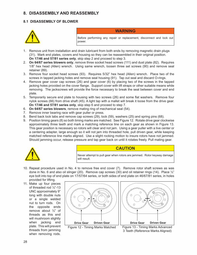
approximately three teeth and mark a matching reference line on each gear as shown in Figure 13. This gear position is necessary so rotors will clear and not jam. Using a gear puller with a live center or a centering adapter, large enough so it will not jam into threaded hole, pull driven gear, while keeping matched reference line marks aligned. Use a slight rocking motion to insure rotors have not jammed. Should jamming occur, release pressure and tap gear back on until it rotates freely. Pull mating gear.
CAUTIONNever attempt to pull gear when rotors are jammed. Rotor keyway damage will result.
10. Repeat procedure used in No. 4 to remove free end cover (7). Remove rotor shaft screws as was done in No. 6 and also oil slinger (20). Remove cap screws (30) and oil retainer rings (14). Place ½” eye bolt into top of end plate on 17/57/64 series, or both sides of end plate on 46/67/81 series, in holes provided for lifting.
11. Make up four pieces of threaded rod ½”-13 UNC approximately 9” long with double nuts or a single welded nut to turn rods. On the opposite ends remove about ½” of threads as this end will mushroom slightly when jacking end plate. This will prevent threads from jamming when removing rods.
Figure 12 - Timing Marks Matched Figure 13 - Timing Marks Advanced3 Teeth (Reference Marks Aligned)
Drive Gear Driven GearDrive Gear Driven Gear
29
Run in equally to remove end plate. Tap out roller bearings (10). Note that each bearing on this end has two identical spacers (57), one on each side of bearing. Tap out seals (54) or (12). Also remove the labyrinth seals (51), as they should be replaced with each overhaul. On 57/81 and 64/67 series, discard O-ring (75) and retain O-ring spacers (74) for reassembly.
12. Remove cap screws (30) and bearing retainer rings (14) from drive end of unit. Remove rotors (1). To remove the rotors from the end plate will require either a two-jaw gear puller with jaws inserted in the oil feed slots of the bearing bore, or a bar-type puller using the tapped holes around the bearing bore.
CAUTIONIf rotors are side by side, position the lobes vertically when removing. If they are one on top of the other, remove top rotor first in a vertical position. Then position bottom rotor vertically and remove.
13. Support end plate with eyebolts and lift strap. Remove temporary cap screws and tap end plate from housing (3). Remove bearings and seals.
14. Clean and inspect parts for damage and wear. Replace all O-rings, seals and bearings at each overhaul.
NOTEIf end plates, housing or end covers are not being reassembled in their original position or some new parts are being used, it will be necessary to clean all paint or rust build-up from the mating surfaces to insure a good seal. Failure to do so could result in excessive end clearances and air or oil leaks.
8.2 ASSEMBLY OF 7000 BLOWER
The assembly procedure is generally the same for all series, but where there are differences, notations are made. Dowel pins are used to locate end plates, housing and end covers in their proper locations relative to each other. Be sure they are in place. An O-ring lubricant should be used on all O-rings.
It is recommended that the gear end rotor shaft bearings be purchased from Tuthill Vacuum & Blower Systems, as they are specially ground to locate the rotors with correct end clearance relative to the gear end plate.
NOTEMake sure all parts are clean and free of any nicks or burrs caused by disassembly. Blowers incorporating lip seals will require all sleeves or seal journals to be polished to remove any nicks and scratches. Failure to polish seal journals will result in seal leakage or damage. Refer to page 34 for seal pressing tools as well as other assembly tools required.
NOTEWhen rebuilding the model 7000 blowers and depending on the series designation, it may be necessary to reseal the joints between the rotor housing, end plates, and end covers. The following sealers are recommended and are available for purchase from Tuthill Vacuum & Blower Systems:
Dow Corning - RTV 737 General Electric - N-SIL
8.2.1 PREPARATION OF END PLATES FOR ASSEMBLY
1. Press the labyrinth seals (51) into seal bores with the lips toward the oil side.
NOTEFor lip seal units put a light coat of silicon in the seal bore of end plate. Install lip seal open side facing up.
30
8.2.2 MECHANICAL SEAL UNITS
2. Install O-ring spacers (74) with grooves up. Install O-rings (75) making sure they are fully seated in their grooves. Apply a thin coat of sealer to O. D. of seal (54) and press into seal bore. Make sure seals are fully seated without deforming. Clean seal carbon with soft tissue and cleaning agent (acetone).
8.2.3 GEAR END ASSEMBLY
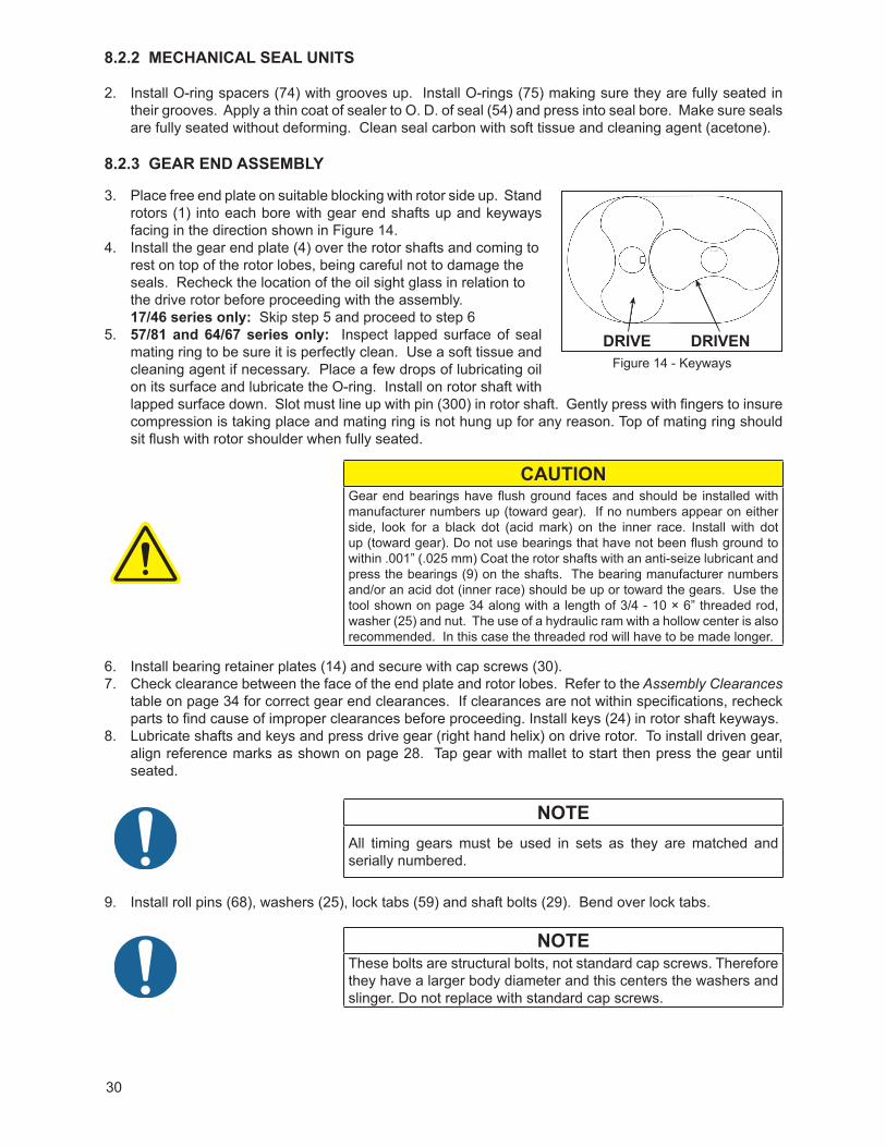
3. Place free end plate on suitable blocking with rotor side up. Stand rotors (1) into each bore with gear end shafts up and keyways facing in the direction shown in Figure 14.
4. Install the gear end plate (4) over the rotor shafts and coming to rest on top of the rotor lobes, being careful not to damage the seals. Recheck the location of the oil sight glass in relation to the drive rotor before proceeding with the assembly. 17/46 series only: Skip step 5 and proceed to step 6
5. 57/81 and 64/67 series only: Inspect lapped surface of seal mating ring to be sure it is perfectly clean. Use a soft tissue and cleaning agent if necessary. Place a few drops of lubricating oil on its surface and lubricate the O-ring. Install on rotor shaft with lapped surface down. Slot must line up with pin (300) in rotor shaft. Gently press with fingers to insure compression is taking place and mating ring is not hung up for any reason. Top of mating ring should sit flush with rotor shoulder when fully seated.
CAUTIONGear end bearings have flush ground faces and should be installed with manufacturer numbers up (toward gear). If no numbers appear on either side, look for a black dot (acid mark) on the inner race. Install with dot up (toward gear). Do not use bearings that have not been flush ground to within .001” (.025 mm) Coat the rotor shafts with an anti-seize lubricant and press the bearings (9) on the shafts. The bearing manufacturer numbers and/or an acid dot (inner race) should be up or toward the gears. Use the tool shown on page 34 along with a length of 3/4 - 10 × 6” threaded rod, washer (25) and nut. The use of a hydraulic ram with a hollow center is also recommended. In this case the threaded rod will have to be made longer.
6. Install bearing retainer plates (14) and secure with cap screws (30).7. Check clearance between the face of the end plate and rotor lobes. Refer to the Assembly Clearances
table on page 34 for correct gear end clearances. If clearances are not within specifications, recheck parts to find cause of improper clearances before proceeding. Install keys (24) in rotor shaft keyways.
8. Lubricate shafts and keys and press drive gear (right hand helix) on drive rotor. To install driven gear, align reference marks as shown on page 28. Tap gear with mallet to start then press the gear until seated.
NOTEAll timing gears must be used in sets as they are matched and serially numbered.
9. Install roll pins (68), washers (25), lock tabs (59) and shaft bolts (29). Bend over lock tabs.
NOTEThese bolts are structural bolts, not standard cap screws. Therefore they have a larger body diameter and this centers the washers and slinger. Do not replace with standard cap screws.
Figure 14 - KeywaysDrive DrivenDRIVE DRIVEN
31
10. Remove the gear end assembly from the free end plate and turn over so the gears are facing down on a solid surface. Place some wood blocking on each side for support.
11. 57/81 and 64/67 series: Place a small bead of an RTV silicone type sealer around the periphery of the housing (3) bores, but inside the bolt pattern. Encircle the dowel pins. Install rotor housing and temporarily secure to end plate with two cap screws (26) and some flat washers. Check clearances between end of lobes and housing using a flat bar and feeler gauges or a depth micrometer. Refer to exploded view for free end clearances.
12. 57/81 and 64/67 series: Put sealer on rotor housing, same as above. All series: Install free end plate and secure in same manner.
13. 57/81 and 64/67 series: Install seal mating rings as was done in Step 4. All series: Install one bearing spacer (57) on each shaft. Lubricate shafts and install roller bearings with inner race flange outward. See Figure 15
14. Install oil retainer rings (14) and cap screws (30). Install roll pin (68) washers (25), oil slinger (20) (on drive rotor), lock tabs (59) and bolts (29). Bend over tabs.
15. Install mounting feet (304) with machined surface against housing and secure with lockwashers (80) and cap screws (307). Install lifting lugs (195) with cap screws (196).
8.2.4 ADJUSTING ROTOR INTERLOBE CLEARANCE
16. The driven gear is made of two pieces. The outer gear shell is fastened to the inner hub with four cap screws and located with two dowel pins. A laminated shim, made up of .003” (.076 mm) laminations, separates the hub and the shell. By removing or adding shim laminations, the gear shell is moved axially relative to the inner hub. Being a helical gear, it rotates as it is moved in or out and the driven rotor turns with it, thus changing the clearance between rotor lobes. Changing the shim thickness .014” (.36 mm) will change the rotor lobe clearance .005” (.13 mm). EXAMPLE: Referring to Figure 16, check the clearance at AA (right hand reading) and BB (left hand reading). If AA reading is .017” (.43 mm) and BB reading is .004” (.10 mm), by removing.018” (.46 mm) shims, the readings should then read AA .011” (.28 mm) and BB .010” (.25 mm). To determine the amount of shim to add or remove, subtract the smaller reading from the larger and multiply the result by 1.4. (.017” [.43 mm] -.004” [.10 mm] = .013” [.33 mm] × 1.4 = .018” [.46 mm]) If the right side reading is higher than the left side, remove shim. If the right side reading is lower, add shim.
Figure 15 - Roller Bearings Illustration
HOUSING END COVER
Figure 16 - Checking Rotor Interlobe Clearance
A
B B
B
A
B
AA
A A
B
A
BB
A
B
LONG FEELER GAUGE
LONG FEELER GAUGE
RECORD A-AREADING HERE
RECORD A-AREADING HERE
RECORD B-BREADING HERE
3 LOBE
2 LOBE
RECORD B-BREADING HERE
B B
BB
B
BB
B
B
B
B
B
A
A
AA
A
A
A
A
A
A
A
ADRIVE
DRIVEN DRIVEDRIVEN
32
The final readings should be within .002” (.05 mm) of each other. When removing gear shell from driven gear, it is not necessary to remove gear lock bolt. Make sure bolt locks are in place because the dowel pins must come off with the gear shell.
17. Install inner race of drive shaft roller bearing (50) onto drive shaft. Flange side must be inboard. See special tool drawings. Install outer race with rollers into cover bore flush with inside boss. Install oil slingers (395) back to back on drive shaft flange. Make sure both mating surfaces are clean and free of burrs-then mount drive shaft to gear and secure with-nylok cap screws (29). Check drive shaft runout at seal journal. Do not exceed .003” (.08 mm) T.I.R.
18. Remove temporary cap screws from gear end of housing and place bead of silicone around the periphery of the end plate. Encircle the dowel pins. Install cover (6) and cap screws (26). The use of two ½”-13 threaded rods as guide screws is recommended.
8.2.5 DRIVE SHAFT SEAL ASSEMBLY
19. 17/46 and 57/81 series: Press drive shaft lip seal (13) into seal housing (91). This is a double lip seal; pack with grease. Install O-ring (92) and assemble to cover with hex cap screws. 64/67 series: a. Install O-ring (75) into seal housing (91) and press in stator portion of mechanical seal (54). See
special tool drawing. Clean face of carbon and mating ring with soft tissue and acetone. Install O-ring (92).
b. Lubricate O-ring in ID of mating ring and carefully slide onto drive shaft with slot up and seat against shoulder. Do not use any tools. Lapped surface should be facing outward.
c. Install seal housing (91) into cover bore and secure with four hex head screws (93).d. With set screws (90) in place install mating ring retainer (89) (flange facing outward) while aligning
pin (300) with slot in mating ring. Secure to shaft with set screws.20. Install free end cover (7) same as gear end.
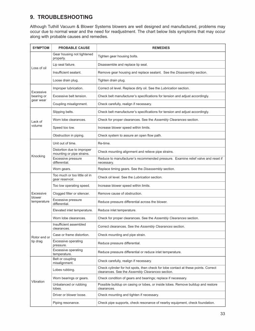
33
9. TROUBLESHOOTINGAlthough Tuthill Vacuum & Blower Systems blowers are well designed and manufactured, problems may occur due to normal wear and the need for readjustment. The chart below lists symptoms that may occur along with probable causes and remedies.
SYMPTOM PROBABLE CAUSE REMEDIES
Loss of oil
Gear housing not tightened properly. Tighten gear housing bolts.
Lip seal failure. Disassemble and replace lip seal.
Insufficient sealant. Remove gear housing and replace sealant. See the Disassembly section.
Loose drain plug. Tighten drain plug.
Excessive bearing or gear wear
Improper lubrication. Correct oil level. Replace dirty oil. See the Lubrication section.
Excessive belt tension. Check belt manufacturer’s specifications for tension and adjust accordingly.
Coupling misalignment. Check carefully, realign if necessary.
Lack of volume
Slipping belts. Check belt manufacturer’s specifications for tension and adjust accordingly.
Worn lobe clearances. Check for proper clearances. See the Assembly Clearances section.
Speed too low. Increase blower speed within limits.
Obstruction in piping. Check system to assure an open flow path.
Knocking
Unit out of time. Re-time.
Distortion due to improper mounting or pipe strains. Check mounting alignment and relieve pipe strains.
Excessive pressure differential.
Reduce to manufacturer’s recommended pressure. Examine relief valve and reset if necessary.
Worn gears. Replace timing gears. See the Disassembly section.
Excessive blower temperature
Too much or too little oil in gear reservoir. Check oil level. See the Lubrication section.
Too low operating speed. Increase blower speed within limits.
Clogged filter or silencer. Remove cause of obstruction.
Excessive pressure differential. Reduce pressure differential across the blower.
Elevated inlet temperature. Reduce inlet temperature.
Worn lobe clearances. Check for proper clearances. See the Assembly Clearances section.
Rotor end or tip drag
Insufficient assembled clearances. Correct clearances. See the Assembly Clearances section.
Case or frame distortion. Check mounting and pipe strain.
Excessive operating pressure. Reduce pressure differential.
Excessive operating temperature. Reduce pressure differential or reduce inlet temperature.
Vibration
Belt or coupling misalignment. Check carefully, realign if necessary.
Lobes rubbing. Check cylinder for hot spots, then check for lobe contact at these points. Correct clearances. See the Assembly Clearances section.
Worn bearings or gears. Check condition of gears and bearings; replace if necessary.
Unbalanced or rubbing lobes.
Possible buildup on casing or lobes, or inside lobes. Remove buildup and restore clearances.
Driver or blower loose. Check mounting and tighten if necessary.
Piping resonance. Check pipe supports, check resonance of nearby equipment, check foundation.
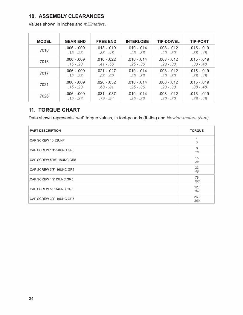
34
10. ASSEMBLY CLEARANCESValues shown in inches and millimeters.
MODEL GEAR END FREE END INTERLOBE TIP-DOWEL TIP-PORT
7010 .006 - .009.15 - .23
.013 - .019.33 - .48
.010 - .014.25 - .36
.008 - .012.20 - .30
.015 - .019.38 - .48
7013 .006 - .009.15 - .23
.016 - .022.41 - .56
.010 - .014.25 - .36
.008 - .012.20 - .30
.015 - .019.38 - .48
7017 .006 - .009.15 - .23
.021 - .027.53 - .69
.010 - .014.25 - .36
.008 - .012.20 - .30
.015 - .019.38 - .48
7021 .006 - .009.15 - .23
.026 - .032.68 - .81
.010 - .014.25 - .36
.008 - .012.20 - .30
.015 - .019.38 - .48
7026 .006 - .009.15 - .23
.031 - .037.79 - .94
.010 - .014.25 - .36
.008 - .012.20 - .30
.015 - .019.38 - .48
11. TORQUE CHARTData shown represents “wet” torque values, in foot-pounds (ft.-lbs) and Newton-meters (N-m).
PART DESCRIPTION TORQUE
CAP SCREW 10-32UNF 45
CAP SCREW 1/4”-20UNC GR5 810
CAP SCREW 5/16”-18UNC GR5 1520
CAP SCREW 3/8”-16UNC GR5 3345
CAP SCREW 1/2”13UNC GR5 78106
CAP SCREW 5/8”14UNC GR5 123167
CAP SCREW 3/4”-10UNC GR5 260350
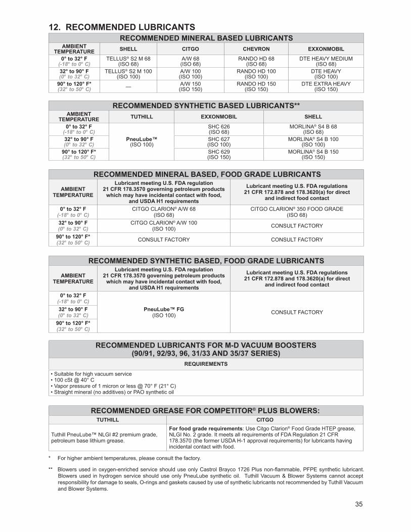
35
12. RECOMMENDED LUBRICANTS
RECOMMENDED MINERAL BASED, FOOD GRADE LUBRICANTS
AMBIENTTEMPERATURE
Lubricant meeting U.S. FDA regulation21 CFR 178.3570 governing petroleum products
which may have incidental contact with food, and USDA H1 requirements
Lubricant meeting U.S. FDA regulations 21 CFR 172.878 and 178.3620(a) for direct
and indirect food contact
0° to 32° F(-18° to 0° C)
CITGO CLARION® A/W 68(ISO 68)
CITGO CLARION® 350 FOOD GRADE(ISO 68)
32° to 90° F(0° to 32° C)
CITGO CLARION® A/W 100(ISO 100) CONSULT FACTORY
90° to 120° F*(32° to 50° C) CONSULT FACTORY CONSULT FACTORY
RECOMMENDED SYNTHETIC BASED, FOOD GRADE LUBRICANTS
AMBIENTTEMPERATURE
Lubricant meeting U.S. FDA regulation21 CFR 178.3570 governing petroleum products
which may have incidental contact with food, and USDA H1 requirements
Lubricant meeting U.S. FDA regulations 21 CFR 172.878 and 178.3620(a) for direct
and indirect food contact
0° to 32° F(-18° to 0° C)
PneuLube™ FG (ISO 100) CONSULT FACTORY32° to 90° F
(0° to 32° C)90° to 120° F*(32° to 50° C)
RECOMMENDED LUBRICANTS FOR M-D VACUUM BOOSTERS(90/91, 92/93, 96, 31/33 AND 35/37 SERIES)
REQUIREMENTS
• Suitable for high vacuum service• 100 cSt @ 40° C• Vapor pressure of 1 micron or less @ 70° F (21° C)• Straight mineral (no additives) or PAO synthetic oil
RECOMMENDED GREASE FOR COMPETITOR® PLUS BLOWERS:TUTHILL CITGO
Tuthill PneuLube™ NLGI #2 premium grade, petroleum base lithium grease.
For food grade requirements: Use Citgo Clarion® Food Grade HTEP grease, NLGI No. 2 grade. It meets all requirements of FDA Regulation 21 CFR 178.3570 (the former USDA H-1 approval requirements) for lubricants having incidental contact with food.
RECOMMENDED LUBRICANTS FOR ROTARY BLOWERS AND VACUUM BOOSTERS RECOMMENDED MINERAL BASED LUBRICANTS
AMBIENTTEMPERATURE SHELL CITGO CHEVRON ExxONMOBIL
0° to 32° F(-18° to 0° C)
TELLUS® S2 M 68(ISO 68)
A/W 68(ISO 68)
RANDO HD 68(ISO 68)
DTE HEAVY MEDIUM(ISO 68)
32° to 90° F(0° to 32° C)
TELLUS® S2 M 100(ISO 100)
A/W 100(ISO 100)
RANDO HD 100(ISO 100)
DTE HEAVY(ISO 100)
90° to 120° F*(32° to 50° C) — A/W 150
(ISO 150)RANDO HD 150
(ISO 150)DTE EXTRA HEAVY
(ISO 150)
RECOMMENDED SYNTHETIC BASED LUBRICANTS**AMBIENT
TEMPERATURE TUTHILL ExxONMOBIL SHELL
0° to 32° F(-18° to 0° C)
PneuLube™ (ISO 100)
SHC 626(ISO 68)
MORLINA® S4 B 68(ISO 68)
32° to 90° F(0° to 32° C)
SHC 627(ISO 100)
MORLINA® S4 B 100(ISO 100)
90° to 120° F*(32° to 50° C)
SHC 629(ISO 150)
MORLINA® S4 B 150(ISO 150)
* For higher ambient temperatures, please consult the factory.
** Blowers used in oxygen-enriched service should use only Castrol Brayco 1726 Plus non-fl ammable, PFPE synthetic lubricant. Blowers used in hydrogen service should use only PneuLube synthetic oil. Tuthill Vacuum & Blower Systems cannot accept responsibility for damage to seals, O-rings and gaskets caused by use of synthetic lubricants not recommended by Tuthill Vacuum and Blower Systems.
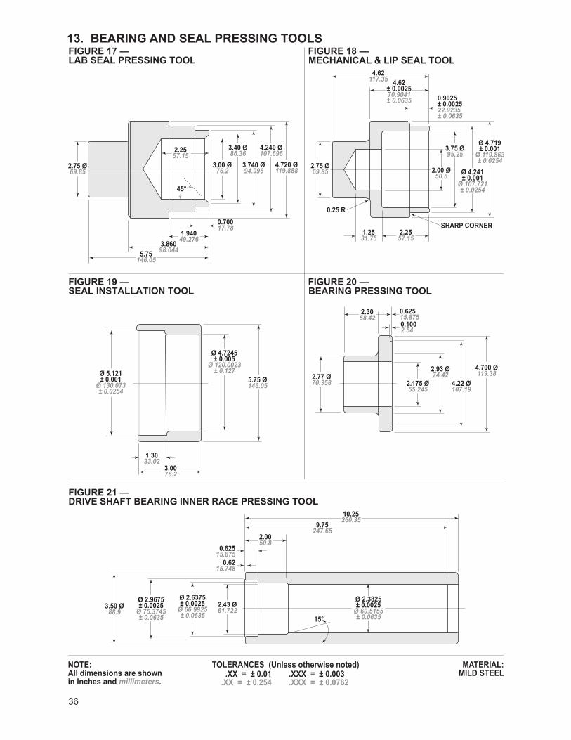
36
13. BEARING AND SEAL PRESSING TOOLSLAB SEAL PRESSING TOOL MECHANICAL & LIP SEAL TOOLFIGURE 17 — FIGURE 18 —
SEAL INSTALLATION TOOL BEARING PRESSING TOOLFIGURE 19 —
DRIVE SHAFT BEARING INNER RACE PRESSING TOOLFIGURE 21 —
FIGURE 20 —
2.75 Ø69.85
5.75 Ø146.05
3.50 Ø88.9
2.43 Ø61.722
0.6215.748
0.62515.875
2.0050.8
9.75247.65
10.25260.35
2.77 Ø70.358
4.700 Ø119.38
4.22 Ø107.19
2.175 Ø55.245
2.93 Ø74.42
2.3058.42
0.62515.8750.1002.54
1.3033.02
3.0076.2
2.75 Ø69.85
1.2531.75
2.2557.15
4.62117.35 4.62
± 0.002570.9041± 0.0635 0.9025
± 0.002522.9235± 0.0635
2.00 Ø50.8
3.75 Ø95.25
Ø 4.241± 0.001
Ø 107.721± 0.0254
Ø 5.121± 0.001
Ø 130.073± 0.0254
Ø 4.7245± 0.005
Ø 120.0023± 0.127
Ø 4.719± 0.001
Ø 119.863± 0.0254
SHARP CORNER
0.25 R
3.00 Ø76.2
45°
15°
3.40 Ø86.36
3.740 Ø94.996
4.720 Ø119.888
4.240 Ø107.6962.25
57.15
0.70017.78
1.94049.2763.860
98.0445.75146.05
Ø 2.9675± 0.0025
Ø 75.3745± 0.0635
Ø 2.3825± 0.0025
Ø 60.5155± 0.0635
Ø 2.6375± 0.0025
Ø 66.9925± 0.0635
NOTE:All dimensions are shown in Inches and millimeters.
MATERIAL:MILD STEEL
TOLERANCES (Unless otherwise noted) .XX = ± 0.01 .XXX = ± 0.003.XX = ± 0.254 .XXX = ± 0.0762
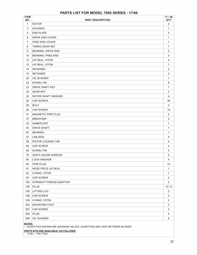
37
PARTS LIST FOR MODEL 7000 SERIES - 17/46ITEM NO. PART DESCRIPTION
17 / 46 QTY
1 ROTOR 2
3 HOUSING 1
4 END PLATE 2
6 DRIVE END COVER 1
7 FREE END COVER 1
8 TIMING GEAR SET 1
9 BEARING, DRIVE END 2
10 BEARING, FREE END 2
12 LIP SEAL, VITON 4
13 LIP SEAL, VITON 1
14 RETAINER 2
15 RETAINER 2
20 OIL SLINGER 1
22 DOWEL PIN 8
23 DRIVE SHAFT KEY 1
24 GEAR KEY 2
25 ROTOR SHAFT WASHER 4
26 CAP SCREW 36
29 BOLT 4
30 CAP SCREW 16
31 MAGNETIC PIPE PLUG 2
37 BREATHER 2
42 NAMEPLATE 1
45 DRIVE SHAFT 1
50 BEARING 1
51 LAB SEAL 4
59 ROTOR LOCKING TAB 4
66 CAP SCREW 4
68 DOWEL PIN 4
70 SIGHT GAUGE WINDOW 2
80 LOCK WASHER 4
85 PIPE PLUG 14
91 NOSE PIECE LIP SEAL 1
92 O-RING, VITON 1
93 CAP SCREW 4
100 STRAIGHT THREAD ADAPTOR 2
109 PLUG 12 / 0
195 LIFTING LUG 2
196 CAP SCREW 2
199 O-RING, VITON 2
304 MOUNTING FOOT 2
307 CAP SCREW 4
339 PLUG 4
395 OIL SLINGER 2
NOTES:• QUANTITIES SHOWN ARE MAXIMUM VALUES; QUANTITIES MAY VARY BETWEEN BLOWER
PARTS KITS ARE AVAILABLE, AS FOLLOWS:17/46 — P/N 77051

38
PARTS LIST FOR MODEL 7000 SERIES - 57/81ITEM NO. PART DESCRIPTION
57 / 81 QTY
1 ROTOR 23 HOUSING 14 END PLATE 26 DRIVE END COVER 17 FREE END COVER 18 TIMING GEAR SET 19 BEARING, DRIVE END 210 BEARING, FREE END 213 LIP SEAL, VITON 114 RETAINER 215 RETAINER 220 OIL SLINGER 122 DOWEL PIN 823 DRIVE SHAFT KEY 124 GEAR KEY 225 ROTOR SHAFT WASHER 426 CAP SCREW 3629 BOLT 430 CAP SCREW 1631 MAGNETIC PIPE PLUG 237 BREATHER 242 NAMEPLATE 145 DRIVE SHAFT 150 BEARING 151 LAB SEAL 454 MECHANICAL SEAL 459 ROTOR LOCKING TAB 466 CAP SCREW 468 DOWEL PIN 470 SIGHT GAUGE WINDOW 274 SEALING RING 475 O-RING, VITON 480 LOCK WASHER 485 PIPE PLUG 1491 NOSE PIECE LIP SEAL 192 O-RING, VITON 193 CAP SCREW 4
100 STRAIGHT THREAD ADAPTOR 2109 PLUG 4 / —121 PLUG 10 / —195 LIFTING LUG 2196 CAP SCREW 2199 O-RING, VITON 2300 ROLL PIN 4304 MOUNTING FOOT 2307 CAP SCREW 4339 PLUG 4395 OIL SLINGER 2
NOTES:• QUANTITIES SHOWN ARE MAXIMUM VALUES; QUANTITIES MAY VARY BETWEEN BLOWER
PARTS KITS ARE AVAILABLE, AS FOLLOWS:57/81 — P/N 77069
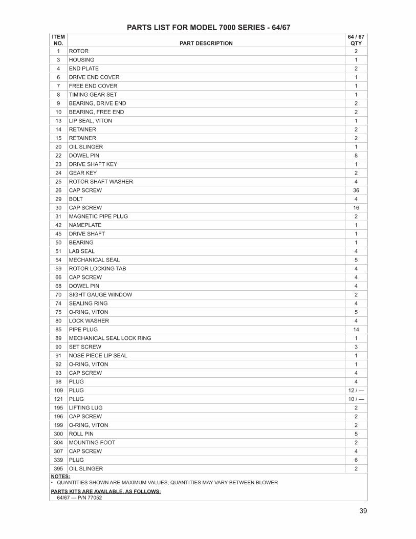
39
PARTS LIST FOR MODEL 7000 SERIES - 64/67ITEM NO. PART DESCRIPTION
64 / 67 QTY
1 ROTOR 23 HOUSING 14 END PLATE 26 DRIVE END COVER 17 FREE END COVER 18 TIMING GEAR SET 19 BEARING, DRIVE END 210 BEARING, FREE END 213 LIP SEAL, VITON 114 RETAINER 215 RETAINER 220 OIL SLINGER 122 DOWEL PIN 823 DRIVE SHAFT KEY 124 GEAR KEY 225 ROTOR SHAFT WASHER 426 CAP SCREW 3629 BOLT 430 CAP SCREW 1631 MAGNETIC PIPE PLUG 242 NAMEPLATE 145 DRIVE SHAFT 150 BEARING 151 LAB SEAL 454 MECHANICAL SEAL 559 ROTOR LOCKING TAB 466 CAP SCREW 468 DOWEL PIN 470 SIGHT GAUGE WINDOW 274 SEALING RING 475 O-RING, VITON 580 LOCK WASHER 485 PIPE PLUG 1489 MECHANICAL SEAL LOCK RING 190 SET SCREW 391 NOSE PIECE LIP SEAL 192 O-RING, VITON 193 CAP SCREW 498 PLUG 4
109 PLUG 12 / —121 PLUG 10 / —195 LIFTING LUG 2196 CAP SCREW 2199 O-RING, VITON 2300 ROLL PIN 5304 MOUNTING FOOT 2307 CAP SCREW 4339 PLUG 6395 OIL SLINGER 2
NOTES:• QUANTITIES SHOWN ARE MAXIMUM VALUES; QUANTITIES MAY VARY BETWEEN BLOWER
PARTS KITS ARE AVAILABLE, AS FOLLOWS:64/67 — P/N 77052
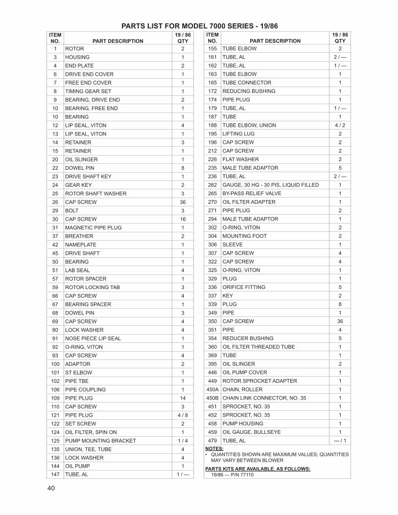
40
PARTS LIST FOR MODEL 7000 SERIES - 19/86ITEM NO. PART DESCRIPTION
19 / 86 QTY
1 ROTOR 23 HOUSING 14 END PLATE 26 DRIVE END COVER 17 FREE END COVER 18 TIMING GEAR SET 19 BEARING, DRIVE END 2
10 BEARING, FREE END 110 BEARING 112 LIP SEAL, VITON 413 LIP SEAL, VITON 114 RETAINER 315 RETAINER 120 OIL SLINGER 122 DOWEL PIN 823 DRIVE SHAFT KEY 124 GEAR KEY 225 ROTOR SHAFT WASHER 326 CAP SCREW 3629 BOLT 330 CAP SCREW 1631 MAGNETIC PIPE PLUG 137 BREATHER 242 NAMEPLATE 145 DRIVE SHAFT 150 BEARING 151 LAB SEAL 457 ROTOR SPACER 159 ROTOR LOCKING TAB 366 CAP SCREW 467 BEARING SPACER 168 DOWEL PIN 369 CAP SCREW 480 LOCK WASHER 491 NOSE PIECE LIP SEAL 192 O-RING, VITON 193 CAP SCREW 4100 ADAPTOR 2101 ST ELBOW 1102 PIPE TBE 1106 PIPE COUPLING 1109 PIPE PLUG 14110 CAP SCREW 3121 PIPE PLUG 4 / 8122 SET SCREW 2124 OIL FILTER, SPIN ON 1125 PUMP MOUNTING BRACKET 1 / 4135 UNION, TEE, TUBE 4136 LOCK WASHER 4144 OIL PUMP 1147 TUBE, AL 1 / —
ITEM NO. PART DESCRIPTION
19 / 86 QTY
155 TUBE ELBOW 2161 TUBE, AL 2 / —162 TUBE, AL 1 / —163 TUBE ELBOW 1165 TUBE CONNECTOR 1172 REDUCING BUSHING 1174 PIPE PLUG 1179 TUBE, AL 1 / —187 TUBE 1188 TUBE ELBOW, UNION 4 / 2195 LIFTING LUG 2196 CAP SCREW 2212 CAP SCREW 2226 FLAT WASHER 2235 MALE TUBE ADAPTOR 5236 TUBE, AL 2 / —262 GAUGE, 30 HG - 30 PIS, LIQUID FILLED 1265 BY-PASS RELIEF VALVE 1270 OIL FILTER ADAPTER 1271 PIPE PLUG 2294 MALE TUBE ADAPTOR 1302 O-RING, VITON 2304 MOUNTING FOOT 2306 SLEEVE 1307 CAP SCREW 4322 CAP SCREW 4325 O-RING, VITON 1329 PLUG 1336 ORIFICE FITTING 5337 KEY 2339 PLUG 8349 PIPE 1350 CAP SCREW 36351 PIPE 4354 REDUCER BUSHING 5360 OIL FILTER THREADED TUBE 1369 TUBE 1395 OIL SLINGER 2446 OIL PUMP COVER 1449 ROTOR SPROCKET ADAPTER 1
450A CHAIN, ROLLER 1450B CHAIN LINK CONNECTOR, NO. 35 1451 SPROCKET, NO. 35 1452 SPROCKET, NO. 35 1458 PUMP HOUSING 1459 OIL GAUGE, BULLSEYE 1479 TUBE, AL — / 1
NOTES:• QUANTITIES SHOWN ARE MAXIMUM VALUES; QUANTITIES
MAY VARY BETWEEN BLOWER
PARTS KITS ARE AVAILABLE, AS FOLLOWS:19/86 — P/N 77110
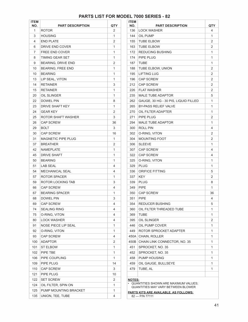
41
PARTS LIST FOR MODEL 7000 SERIES - 82ITEM NO. PART DESCRIPTION QTY
1 ROTOR 2
3 HOUSING 1
4 END PLATE 2
6 DRIVE END COVER 1
7 FREE END COVER 1
8 TIMING GEAR SET 1
9 BEARING, DRIVE END 2
10 BEARING, FREE END 1
10 BEARING 1
13 LIP SEAL, VITON 1
14 RETAINER 3
15 RETAINER 1
20 OIL SLINGER 1
22 DOWEL PIN 8
23 DRIVE SHAFT KEY 1
24 GEAR KEY 2
25 ROTOR SHAFT WASHER 3
26 CAP SCREW 36
29 BOLT 3
30 CAP SCREW 16
31 MAGNETIC PIPE PLUG 1
37 BREATHER 2
42 NAMEPLATE 1
45 DRIVE SHAFT 1
50 BEARING 1
51 LAB SEAL 4
54 MECHANICAL SEAL 4
57 ROTOR SPACER 1
59 ROTOR LOCKING TAB 3
66 CAP SCREW 4
67 BEARING SPACER 1
68 DOWEL PIN 3
69 CAP SCREW 4
74 SEALING RING 4
75 O-RING, VITON 4
80 LOCK WASHER 4
91 NOSE PIECE LIP SEAL 1
92 O-RING, VITON 1
93 CAP SCREW 4
100 ADAPTOR 2
101 ST ELBOW 1
102 PIPE TBE 1
106 PIPE COUPLING 1
109 PIPE PLUG 14
110 CAP SCREW 3
121 PIPE PLUG 10
122 SET SCREW 2
124 OIL FILTER, SPIN ON 1
125 PUMP MOUNTING BRACKET 1
135 UNION, TEE, TUBE 4
ITEM NO. PART DESCRIPTION QTY136 LOCK WASHER 4
144 OIL PUMP 1
155 TUBE ELBOW 2
163 TUBE ELBOW 2
172 REDUCING BUSHING 1
174 PIPE PLUG 1
187 TUBE 1
188 TUBE ELBOW, UNION 2
195 LIFTING LUG 2
196 CAP SCREW 2
212 CAP SCREW 2
226 FLAT WASHER 2
235 MALE TUBE ADAPTOR 5
262 GAUGE, 30 HG - 30 PIS, LIQUID FILLED 1
265 BY-PASS RELIEF VALVE 1
270 OIL FILTER ADAPTER 1
271 PIPE PLUG 2
294 MALE TUBE ADAPTOR 1
300 ROLL PIN 4
302 O-RING, VITON 2
304 MOUNTING FOOT 2
306 SLEEVE 1
307 CAP SCREW 4
322 CAP SCREW 4
325 O-RING, VITON 1
329 PLUG 1
336 ORIFICE FITTING 5
337 KEY 2
339 PLUG 8
349 PIPE 1
350 CAP SCREW 36
351 PIPE 4
354 REDUCER BUSHING 5
360 OIL FILTER THREADED TUBE 1
369 TUBE 1
395 OIL SLINGER 2
446 OIL PUMP COVER 1
449 ROTOR SPROCKET ADAPTER 1
450A CHAIN, ROLLER 1
450B CHAIN LINK CONNECTOR, NO. 35 1
451 SPROCKET, NO. 35 1
452 SPROCKET, NO. 35 1
458 PUMP HOUSING 1
459 OIL GAUGE, BULLSEYE 1
479 TUBE, AL 1
NOTES:• QUANTITIES SHOWN ARE MAXIMUM VALUES;
QUANTITIES MAY VARY BETWEEN BLOWER
PARTS KITS ARE AVAILABLE, AS FOLLOWS:82 — P/N 77111
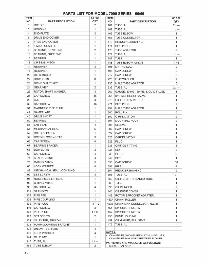
42
PARTS LIST FOR MODEL 7000 SERIES - 66/69ITEM NO. PART DESCRIPTION
66 / 69 QTY
1 ROTOR 23 HOUSING 14 END PLATE 26 DRIVE END COVER 17 FREE END COVER 18 TIMING GEAR SET 19 BEARING, DRIVE END 2
10 BEARING, FREE END 110 BEARING 113 LIP SEAL, VITON 114 RETAINER 315 RETAINER 120 OIL SLINGER 122 DOWEL PIN 823 DRIVE SHAFT KEY 124 GEAR KEY 225 ROTOR SHAFT WASHER 326 CAP SCREW 3629 BOLT 330 CAP SCREW 1631 MAGNETIC PIPE PLUG 142 NAMEPLATE 145 DRIVE SHAFT 150 BEARING 151 LAB SEAL 454 MECHANICAL SEAL 557 ROTOR SPACER 159 ROTOR LOCKING TAB 366 CAP SCREW 467 BEARING SPACER 168 DOWEL PIN 369 CAP SCREW 474 SEALING RING 475 O-RING, VITON 580 LOCK WASHER 489 MECHANICAL SEAL LOCK RING 190 SET SCREW 391 NOSE PIECE LIP SEAL 192 O-RING, VITON 193 CAP SCREW 4101 ST ELBOW 1102 PIPE TBE 1106 PIPE COUPLING 1109 PIPE PLUG 14 / 12110 CAP SCREW 3121 PIPE PLUG 4 / 10122 SET SCREW 2124 OIL FILTER, SPIN ON 1125 PUMP MOUNTING BRACKET 1135 UNION, TEE, TUBE 4136 LOCK WASHER 4144 OIL PUMP 1147 TUBE, AL 1 / —155 TUBE ELBOW 2
ITEM NO. PART DESCRIPTION
66 / 69 QTY
161 TUBE, AL 2 / —162 TUBE, AL 1 / —163 TUBE ELBOW 1165 TUBE CONNECTOR 1172 REDUCING BUSHING 1174 PIPE PLUG 1178 TUBE ADAPTOR 2179 TUBE, AL 1 / —187 TUBE 1188 TUBE ELBOW, UNION 4 / 2195 LIFTING LUG 2196 CAP SCREW 2212 CAP SCREW 2226 FLAT WASHER 2235 MALE TUBE ADAPTOR 5236 TUBE, AL 2 / —262 GAUGE, 30 HG - 30 PIS, LIQUID FILLED 1265 BY-PASS RELIEF VALVE 1270 OIL FILTER ADAPTER 1271 PIPE PLUG 2294 MALE TUBE ADAPTOR 1300 ROLL PIN 5302 O-RING, VITON 2304 MOUNTING FOOT 2306 SLEEVE 1307 CAP SCREW 4322 CAP SCREW 4325 O-RING, VITON 1329 PLUG 1336 ORIFICE FITTING 5337 KEY 2339 PLUG 8349 PIPE 1350 CAP SCREW 36351 PIPE 4354 REDUCER BUSHING 5355 TUBE, AL 1 / —360 OIL FILTER THREADED TUBE 1369 TUBE 1395 OIL SLINGER 2446 OIL PUMP COVER 1449 ROTOR SPROCKET ADAPTER 1
450A CHAIN, ROLLER 1450B CHAIN LINK CONNECTOR, NO. 35 1451 SPROCKET, NO. 35 1452 SPROCKET, NO. 35 1458 PUMP HOUSING 1459 OIL GAUGE, BULLSEYE 1479 TUBE, AL — / 1
NOTES:• QUANTITIES SHOWN ARE MAXIMUM VALUES;
QUANTITIES MAY VARY BETWEEN BLOWER
PARTS KITS ARE AVAILABLE, AS FOLLOWS:66/69 — P/N 77101
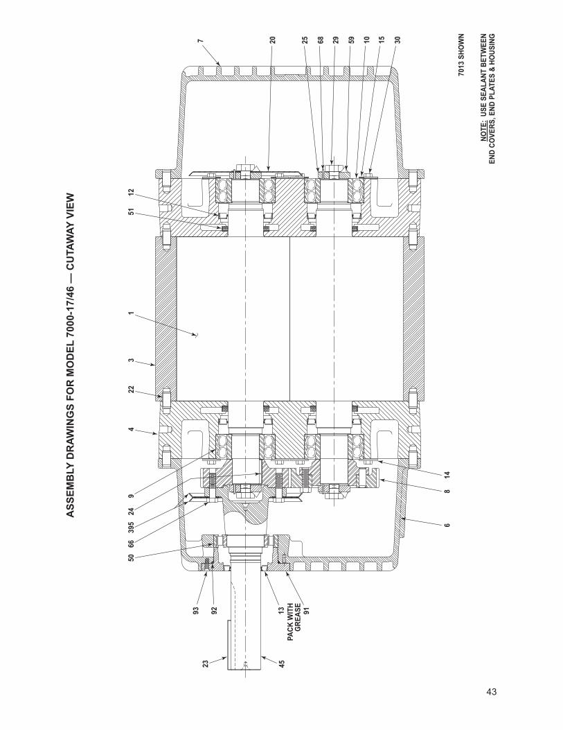
43
ASS
EMB
LY D
RAW
ING
S FO
R M
OD
EL 7
000-
17/4
6 —
CU
TAW
AY V
IEW
614
8
PACK
WIT
H G
REAS
E91
4513
239293
5024
395
669
43
221
301510
1251
29 5925 68207
NOTE
: US
E SE
ALAN
T BE
TWEE
NEN
D CO
VERS
, END
PLA
TES
& HO
USIN
G
7013
SHO
WN
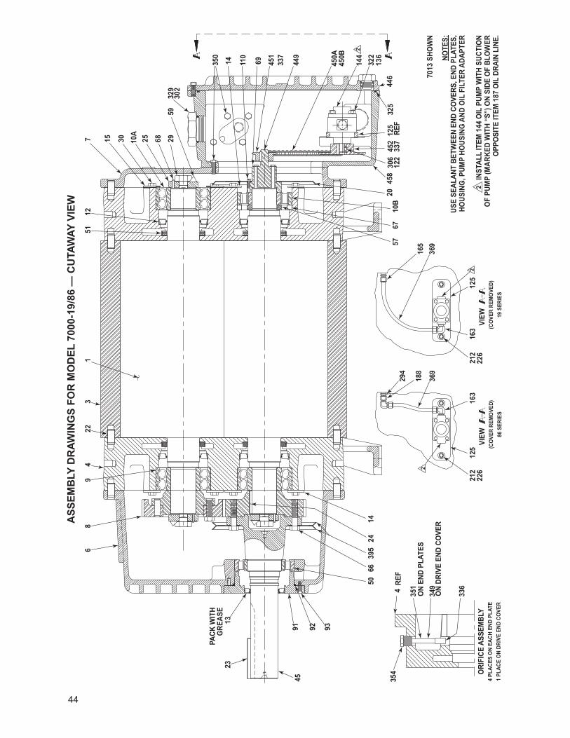
44
ASS
EMB
LY D
RAW
ING
S FO
R M
OD
EL 7
000-
19/8
6 —
CU
TAW
AY V
IEW
ON
DRIV
E EN
D CO
VER
92 93
6650
2439
5
336
ON
END
PLAT
ES34
9
351
354
4RE
F
PACK
WIT
HG
REAS
E
4591
2313
86
229
43
1
337
452
125
212
2262
212
163
226
163
188
369
294
5710
B67
122
306
458
20
212
5
369
165
322
REF
125
325
136
446
144
450B
450A
2
337
449
451
69110
14350
6859
292510A
30157
14
1251
329
302
ORI
FICE
ASS
EMBL
Y4
PLAC
ES O
N EA
CH E
ND P
LATE
1 PL
ACE
ON
DRIV
E EN
D CO
VER
V
IEW
(C
OVE
R RE
MO
VED)
86 S
ERIE
S
V
IEW
(C
OVE
R RE
MO
VED)
19 S
ERIE
S
NOTE
S:US
E SE
ALAN
T BE
TWEE
N EN
D CO
VERS
, END
PLA
TES,
HO
USIN
G, P
UMP
HOUS
ING
AND
OIL
FIL
TER
ADAP
TER
2 IN
STAL
L IT
EM 1
44 O
IL P
UMP
WIT
H SU
CTIO
N O
F PU
MP
(MAR
KED
WIT
H “S
”) O
N SI
DE O
F BL
OW
ER
OPP
OSI
TE IT
EM 1
87 O
IL D
RAIN
LIN
E.
7013
SHO
WN
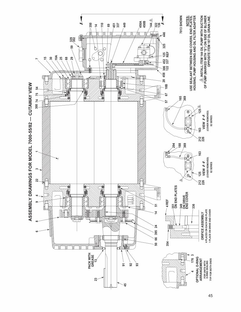
45
ASS
EMB
LY D
RAW
ING
S FO
R M
OD
EL 7
000-
55/8
2 —
CU
TAW
AY V
IEW
92 93
5066
395
24
336
ON
END
PLAT
ES34
9
351
1451
354
REF
4
PACK
WIT
HG
REAS
E
4591
2313
86
229
43
1
452
337
125
226
2122
212
163
163
226
369
188
294
5767
10B
458
306
2012
2
212
5
165
369
322
325
125
REF
136
446
450B
144
450A
2
300
7454
75
337
449
69 451
14 110
350
68 2959
2510A
302
329
30157
417
63
ON
DRIV
E EN
D CO
VER
OPT
IONA
L O
-RIN
G
ARRA
NGEM
ENT
FOR
UNIT
S W
ITH
O-R
ING
SEA
LING
TYP
FOR
BOTH
END
S
ORI
FICE
ASS
EMBL
Y4
PLAC
ES O
N EA
CH E
ND P
LATE
1 PL
ACE
ON
DRIV
E EN
D CO
VER
VI
EW
(CO
VER
REM
OVE
D)82
SER
IES
VI
EW
(CO
VER
REM
OVE
D)82
SER
IES
NOTE
S:US
E SE
ALAN
T BE
TWEE
N EN
D CO
VERS
, END
PLA
TES,
HO
USIN
G, P
UMP
HOUS
ING
AND
OIL
FIL
TER
ADAP
TER
2 IN
STAL
L IT
EM 1
44 O
IL P
UMP
WIT
H SU
CTIO
N O
F PU
MP
(MAR
KED
WIT
H “S
”) O
N SI
DE O
F BL
OW
ER
OPP
OSI
TE IT
EM 1
87 O
IL D
RAIN
LIN
E.
7013
SHO
WN
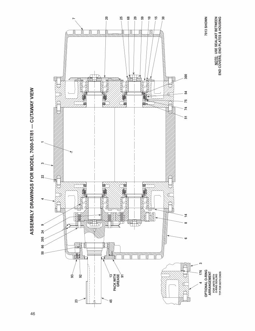
46
ASS
EMB
LY D
RAW
ING
S FO
R M
OD
EL 7
000-
57/8
1 —
CU
TAW
AY V
IEW
6
176
43
148
PACK
WIT
H G
REAS
E 91
4513
239293
5024
395
669
43
221
5175
5474
300
3010 1559296825207
NOTE
: US
E SE
ALAN
T BE
TWEE
NEN
D CO
VERS
, END
PLA
TES
& HO
USIN
G
7013
SHO
WN
OPT
IONA
L O
-RIN
G
ARRA
NGEM
ENT
FOR
UNIT
S W
ITH
O-R
ING
SEA
LING
TYP
FOR
BOTH
END
S
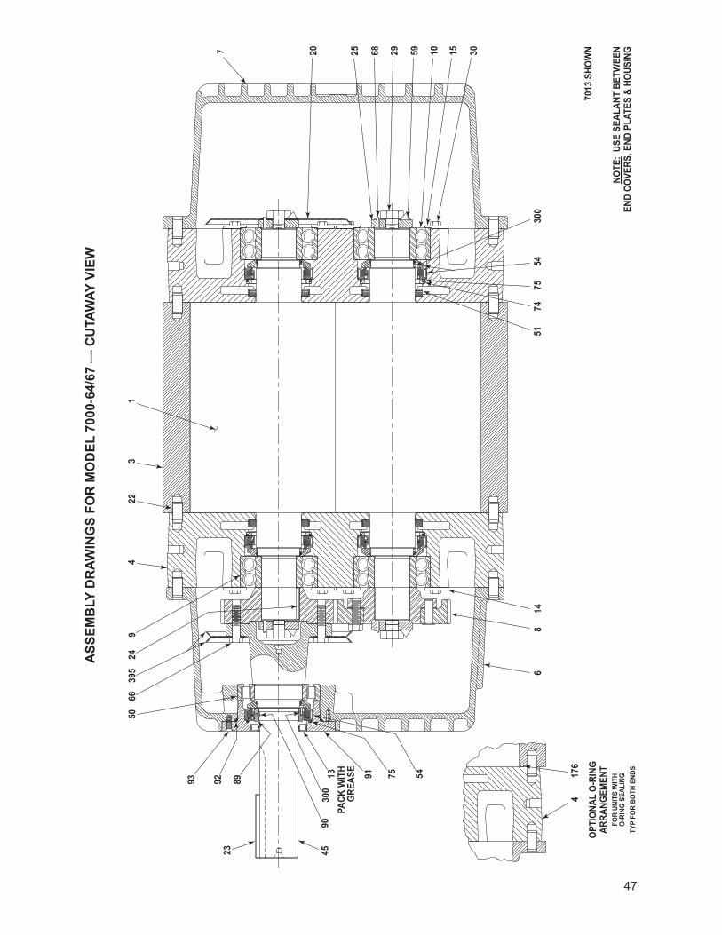
47
ASS
EMB
LY D
RAW
ING
S FO
R M
OD
EL 7
000-
64/6
7 —
CU
TAW
AY V
IEW
614
8
9113PA
CK W
ITH
GRE
ASE
75 54
4530
090
92 8993
23
5024
395
669
43
221
5154
7475
300
10 15 3068 29 5925207
176
4
OPT
IONA
L O
-RIN
G
ARRA
NGEM
ENT
FOR
UNIT
S W
ITH
O-R
ING
SEA
LING
TYP
FOR
BOTH
END
S
NOTE
: US
E SE
ALAN
T BE
TWEE
NEN
D CO
VERS
, END
PLA
TES
& HO
USIN
G
7013
SHO
WN
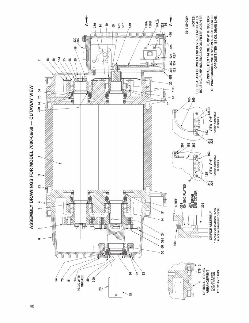
48
ASS
EMB
LY D
RAW
ING
S FO
R M
OD
EL 7
000-
66/6
9 —
CU
TAW
AY V
IEW
92 93
6650
395
24
336
349
351
1451
354
REF
4
4590
23
300
8954
PACK
WIT
HG
REAS
E
139175
86
229
43
1
337
452
125
226
2122
212
163
163
226
369
188
294
5767
10B
122
458
306
20
212
5
165
369
322
325
125
REF
136
446
450B
144
450A
2
300
7475
54
337
449
451
69110
14350
68 2959
10A
25
302
329
30157
417
63
ON
END
PLAT
ES
ON
DRIV
E EN
D CO
VER
OPT
IONA
L O
-RIN
G
ARRA
NGEM
ENT
FOR
UNIT
S W
ITH
O-R
ING
SEA
LING
TYP
FOR
BOTH
END
S
ORI
FICE
ASS
EMBL
Y4
PLAC
ES O
N EA
CH E
ND P
LATE
1 PL
ACE
ON
DRIV
E EN
D CO
VER
VI
EW
(CO
VER
REM
OVE
D)69
SER
IES
VI
EW
(CO
VER
REM
OVE
D)66
SER
IES
NOTE
S:US
E SE
ALAN
T BE
TWEE
N EN
D CO
VERS
, END
PLA
TES,
HO
USIN
G, P
UMP
HOUS
ING
AND
OIL
FIL
TER
ADAP
TER
2 IN
STAL
L IT
EM 1
44 O
IL P
UMP
WIT
H SU
CTIO
N O
F PU
MP
(MAR
KED
WIT
H “S
”) O
N SI
DE O
F BL
OW
ER
OPP
OSI
TE IT
EM 1
87 O
IL D
RAIN
LIN
E.
7013
SHO
WN
49
DECLARATION OF INCORPORATION
Herewith we declare that the items detailed below are in conformity with the provisions of the Machinery Directive 2006/42/EC.
Information on the items detailed are compiled per the Machinery Directive 2006/42/EC, Annex VII, part A and are the responsibility of the person listed below.
The items detailed below must not be put into service until the machinery into which it is to be incorporated has been declared in conformity with the provisions of the relevant directive(s).
Other directives and standards that apply to this Declaration of Incorporation:
EN 1012-1: 1996 - Compressors and vacuum pumps - Safety requirements - Part 1: Compressors
The scope of the Declaration of Incorporation is for bare shaft Rotary Positive Displacement (PD Plus®) Blowers
Model 7000
17/19 – Horizontal Air Flow
46/86 – Vertical Air Flow
57/55 – Horizontal Flow, Single Envelope Gastight
81/82 – Vertical Flow, Single Envelope Gastight
64/66 – Horizontal Flow, Double Envelope Gastight
67/69 – Vertical Flow, Double Envelope Gastight
The person authorized to compile the technical file is Xavier Lambert, Tuthill Corporation, Parc Industriel Wavre Nord-Avenue Vesale 30, B-1300 Wavre Belgium.
Ron RinkeDirector of Engineering, TVBS – Blower Systems
Tuthill Vacuum & Blower Systems4840 West Kearney StreetP.O. Box 2877 Springfield, MO USA 65801-0877
WARRANTY – BLOWER PRODUCTSSubject to the terms and conditions hereinafter set forth and set forth in General Terms of Sale, Tuthill Vacuum & Blower Systems (the Seller) warrants products and parts of its manufacture, when shipped, and its work (including installation and start-up) when performed, will be of good quality and will be free from defects in material and workmanship. This warranty applies only to Seller’s equipment, under use and service in accordance with seller’s written instructions, recommendations and ratings for installation, operating, maintenance and service of products, for a period as stated in the table below. Because of varying conditions of installation and operation, all guarantees of performance are subject to plus or minus 5% variation. (Non-standard materials are subject to a plus or minus 10% variation)
PRODUCTTYPE
TYPE OF APPLICATION
ATMOSPHERIC AIR OR PROCESS AIR WITHOUT LIQUIDS PRESENT
PROCESS GASES OTHER THAN AIR, OR ANY LIQUID INJECTED APPLICATION
New(Qx™ models only)
30 months from date of shipment, or 24 months after initial startup date, whichever occurs first. Consult Factory
New(all other models)
24 months from date of shipment, or 18 months after initial startup date, whichever occurs first
18 months from date of shipment, or 12 months after initial startup date, whichever occurs first
Repair 12 months from date of shipment, or remaining warranty period, whichever is greater
12 months from date of shipment, or remaining warranty period, whichever is greater
THIS WARRANTY EXTENDS ONLY TO BUYER AND/OR ORIGINAL END USER, AND IN NO EVENT SHALL THE SELLER BE LIABLE FOR PROPERTY DAMAGE SUSTAINED BY A PERSON DESIGNATED BY THE LAW OF ANY JURISDICTION AS A THIRD PARTY BENEFICIARY OF THIS WARRANTY OR ANY OTHER WARRANTY HELD TO SURVIVE SELLER’S DISCLAIMER.
All accessories furnished by Seller but manufactured by others bear only that manufacturer’s standard warranty.
All claims for defective products, parts, or work under this warranty must be made in writing immediately upon discovery and, in any event within one (1) year from date of shipment of the applicable item and all claims for defective work must be made in writing immediately upon discovery and in any event within one (1) year from date of completion thereof by Seller. Unless done with prior written consent of Seller, any repairs, alterations or disassembly of Seller’s equipment shall void warranty. Installation and transportation costs are not included and defective items must be held for Seller’s inspection and returned to Seller’s Ex-works point upon request.
THERE ARE NO WARRANTIES, EXPRESSED, IMPLIED OR STATUTORY WHICH EXTEND BEYOND THE DESCRIPTION ON THE FACE HEREOF, INCLUDING WITHOUT LIMITATION, THE IMPLIED WARRANTIES OF MERCHANTABILITY AND FITNESS OF PURPOSE.
After Buyer’s submission of a claim as provided above and its approval, Seller shall at its option either repair or replace its product, part, or work at the original Ex-works point of shipment, or refund an equitable portion of the purchase price.
The products and parts sold hereunder are not warranted for operation with erosive or corrosive material or those which may lead to build up of material within the product supplied, nor those which are incompatible with the materials of construction. The Buyer shall have no claim whatsoever and no product or part shall be deemed to be defective by reason of failure to resist erosive or corrosive action nor for problems resulting from build-up of material within the unit nor for problems due to incompatibility with the materials of construction.
Any improper use, operation beyond capacity, substitution of parts not approved by Seller, or any alteration or repair by others in such manner as in Seller’s judgment affects the product materially and adversely shall void this warranty.
No employee or representative of Seller other than an Officer of the Company is authorized to change this warranty in any way or grant any other warranty. Any such change by an Officer of the Company must be in writing.
The foregoing is Seller’s only obligation and Buyer’s only remedy for breach of warranty, and except for gross negligence, willful misconduct and remedies permitted under the General Terms of Sale in the sections on CONTRACT PERFORMANCE, INSPECTION AND ACCEPTANCE and the PATENTS Clause hereof, the foregoing is BUYER’S ONLY REMEDY HEREUNDER BY WAY OF BREACH OF CONTRACT, TORT OR OTHERWISE, WITHOUT REGARD TO WHETHER ANY DEFECT WAS DISCOVERED OR LATENT AT THE TIME OF DELIVERY OF THE PRODUCT OR WORK. In no event shall Buyer be entitled to incidental or consequential damages. Any action for breach of this agreement must commence within one (1) year after the cause of action has occurred.
May 2008
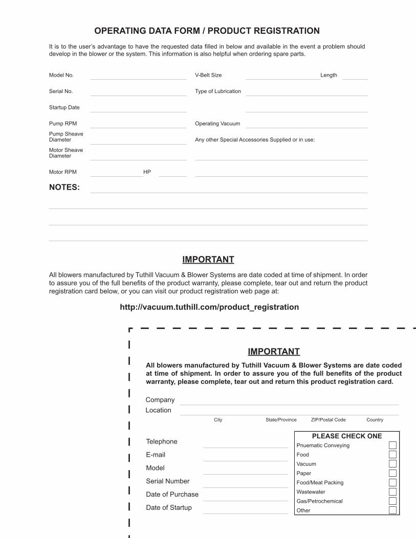
IMPORTANTAll blowers manufactured by Tuthill Vacuum & Blower Systems are date coded at time of shipment. In order to assure you of the full benefits of the product warranty, please complete, tear out and return the product registration card below, or you can visit our product registration web page at:
http://vacuum.tuthill.com/product_registration
PLEASE CHECK ONEPnuematic Conveying
Food
Vacuum
Paper
Food/Meat Packing
Wastewater
Gas/Petrochemical
Other
CompanyLocation
City State/Province ZIP/Postal Code Country
Telephone
Model
Serial Number
Date of Purchase
Date of Startup
IMPORTANTAll blowers manufactured by Tuthill Vacuum & Blower Systems are date coded at time of shipment. In order to assure you of the full benefits of the product warranty, please complete, tear out and return this product registration card.
OPERATING DATA FORM / PRODUCT REGISTRATIONIt is to the user’s advantage to have the requested data filled in below and available in the event a problem should develop in the blower or the system. This information is also helpful when ordering spare parts.
Model No. V-Belt Size Length
Serial No. Type of Lubrication
Startup Date
Pump RPM Operating Vacuum
Pump SheaveDiameter Any other Special Accessories Supplied or in use:
Motor SheaveDiameter
Motor RPM HP
NOTES:

52
NO POSTAGE NECESSARY
IF MAILEDIN THE
UNITED STATES
ATTN. CUSTOMER SERVICETUTHILL VACUUM & BLOWER SYSTEMSPO BOx 2877SPRINGFIELD MO 65890-2150
POSTAGE WILL BE PAID BY ADDRESSEE
BUSINESS REPLY MAILFIRST-CLASS MAIL PERMIT NO. 2912 SPRINGFIELD MO