Embed Size (px)
Citation preview

AS-Interface KompaktstarterCompact Starter
HandbuchManualBestell-Nr./Order No.: 3RK1702-2GB10-2AA0
01415_Kompaktstarter 12.08.1998 10:45 Uhr Seite 1


Important Information, Contents
System Description 1
Installation 2
Wiring 3
Commissioning 4
Hand-held Controller 5
Technical Data 6
SIGUARD Safety Integrated 7
Appendix
Selection Help A
Order Numbers B
Index
AS-Interface
Compact Starter
Manual
Order No.:3RK1702-2GB10-2AA0

Safety guidelines
This manual contains notices which you should observe to ensure your own personal safety, as well as to pro-tect the product and connected equipment. These notices are highlighted in the manual by a warning triangle and are marked as follows according to the level of danger:
Safety noteContains important information for the acceptance test and the safety-related use of the product.
DangerIndicates that death, severe personal injury or substantial property damage will result if proper precautions are not taken.
WarningIndicates that death, severe personal injury or substantial property damage can result if proper precautions are not taken.
WarningIndicates that minor personal injury or property damage can result if proper precautions are not taken.
Cautionindicates that property damage can result if proper precautions are not taken.
ImportantDraws your attention to particularly important information on the product, handling the product, or to a particu-lar part of the documentation.
Qualified personnel
Only qualified personnel should be allowed to install and work on this equipment. Qualified persons are defined as persons who are authorized to commission, to ground, and to tag circuits, equipment, and systems in accordance with established safety practices and standards.
Correct usage
Note the following:
WarningThis device and its components may only be used for the applications described in the catalogue or the techni-cal descriptions, and only in connection with devices or components from other manufacturers which have been approved or recommended by Siemens.
This product can only function correctly and safely if it is transported, stored, set up, and installed correctly, and operated and maintained as recommended.
Brands
SIMATIC®, SIMATIC HMI® and SIMATIC NET® are brands of SIEMENS AG. Some other designations used in these documents are also brands; the owner's rights may be violated if they are used by third parties for their own purposes.
SIEMENS AGIndustry SectorPostfach 48 4890026 NÜRNBERGGERMANY
Siemens Aktiengesellschaft
Siemens AG 2003Technical data subject to change without notice.
Copyright Siemens AG 2003 All rights reserved
The reproduction, transmission or use of this document or its con-tents is not permitted without express written authority. Offenders will be liable for damages. All rights, including rights created by patent grant or registration of a utility model or design, are reserved.
Disclaimer of liability
We have checked this manual to ensure that its contents are correctand applicable in relation to the hardware and software it describes.Despite all our endeavors, however, discrepancies cannot be whollyexcluded and so we cannot guarantee complete correctness andapplicability. However, the data in this manual are reviewed regularlyand any necessary corrections included in subsequent editions. Sug-gestions for improvement are welcomed.
Technical Assistance: Telephone: +49 (0) 911-895-5900 (8°° - 17°° CET) SIEMENS AGFax: +49 (0) 911-895-5907 Technical AssistanceE-mail: [email protected] Würzburger Str. 121Internet: www.siemens.de/lowvoltage/technical-assistance D-90766 Fürth

Deu
tsch
En
gli
sh
Contents
1 System Description 1-1
1.1 What is the Actuator-Sensor Interface (AS-i)? . . . . . . . . . . . . . . . . . . . . . . . 1-21.2 What are the AS-i Compact Starters DS2DI and RS2DI? . . . . . . . . . . . . . . . . . 1-31.3 What are the AS-i Compact Starters EDS2DI and ERS2DI? . . . . . . . . . . . . . . . . 1-41.4 Connection Example . . . . . . . . . . . . . . . . . . . . . . . . . . . . . . . . . . . 1-5
2 Installation 2-1
2.1 Installing the Compact Starter . . . . . . . . . . . . . . . . . . . . . . . . . . . . . . 2-22.2 Dimensions. . . . . . . . . . . . . . . . . . . . . . . . . . . . . . . . . . . . . . . . 2-3
3 Wiring 3-1
3.1 Rules for Wiring . . . . . . . . . . . . . . . . . . . . . . . . . . . . . . . . . . . . . 3-23.2 Compact Starters without a Braking Contact . . . . . . . . . . . . . . . . . . . . . . 3-43.2.1 Making up Connecting Cables . . . . . . . . . . . . . . . . . . . . . . . . . . . . . . 3-43.2.2 Wiring the Power Connectors . . . . . . . . . . . . . . . . . . . . . . . . . . . . . . 3-53.2.3 Electrical Design . . . . . . . . . . . . . . . . . . . . . . . . . . . . . . . . . . . . . 3-73.3 Compact Starters with a 24 V DC Braking Contact. . . . . . . . . . . . . . . . . . . . 3-83.3.1 Making up Connecting Cables . . . . . . . . . . . . . . . . . . . . . . . . . . . . . . 3-83.3.2 Wiring the Power Connectors . . . . . . . . . . . . . . . . . . . . . . . . . . . . . . 3-93.3.3 Electrical Design . . . . . . . . . . . . . . . . . . . . . . . . . . . . . . . . . . . . . 3-113.4 Compact Starters with a 400 V AC resp. 500 V DC Braking Contact . . . . . . . . . . . 3-123.4.1 Making up Connecting Cables . . . . . . . . . . . . . . . . . . . . . . . . . . . . . . 3-123.4.2 Wiring the Power Connectors . . . . . . . . . . . . . . . . . . . . . . . . . . . . . . 3-133.4.3 Electrical Design . . . . . . . . . . . . . . . . . . . . . . . . . . . . . . . . . . . . . 3-153.5 Additional Inputs IN1 and IN2 . . . . . . . . . . . . . . . . . . . . . . . . . . . . . . 3-17
4 Commissioning 4-1
4.1 Compact Starters DS2DI and RS2DI . . . . . . . . . . . . . . . . . . . . . . . . . . . 4-24.1.1 Addressing . . . . . . . . . . . . . . . . . . . . . . . . . . . . . . . . . . . . . . . . 4-24.1.2 Before Commissioning . . . . . . . . . . . . . . . . . . . . . . . . . . . . . . . . . . 4-34.1.3 Operation. . . . . . . . . . . . . . . . . . . . . . . . . . . . . . . . . . . . . . . . . 4-44.1.4 Diagnostics . . . . . . . . . . . . . . . . . . . . . . . . . . . . . . . . . . . . . . . . 4-54.2 Compact Starters EDS2DI and ERS2DI . . . . . . . . . . . . . . . . . . . . . . . . . . 4-84.2.1 Addressing . . . . . . . . . . . . . . . . . . . . . . . . . . . . . . . . . . . . . . . . 4-84.2.2 Before Commissioning . . . . . . . . . . . . . . . . . . . . . . . . . . . . . . . . . . 4-94.2.3 Operation. . . . . . . . . . . . . . . . . . . . . . . . . . . . . . . . . . . . . . . . . 4-114.2.4 Diagnostics . . . . . . . . . . . . . . . . . . . . . . . . . . . . . . . . . . . . . . . . 4-13
5 Hand-held Controller 5-1
5.1 Functions and View. . . . . . . . . . . . . . . . . . . . . . . . . . . . . . . . . . . . 5-25.2 Operation. . . . . . . . . . . . . . . . . . . . . . . . . . . . . . . . . . . . . . . . . 5-35.3 LEDs . . . . . . . . . . . . . . . . . . . . . . . . . . . . . . . . . . . . . . . . . . . 5-45.4 Buttons . . . . . . . . . . . . . . . . . . . . . . . . . . . . . . . . . . . . . . . . . . 5-5
GWA 4NEB 640 0909-32 DS03 i

Contents
6 Technical Data 6-1
6.1 Compact Starter Data . . . . . . . . . . . . . . . . . . . . . . . . . . . . . . . . . . . 6-26.2 Voltages and Currents . . . . . . . . . . . . . . . . . . . . . . . . . . . . . . . . . . . 6-36.3 Braking Current Circuit . . . . . . . . . . . . . . . . . . . . . . . . . . . . . . . . . . 6-46.4 Additional Inputs IN1 and IN2 . . . . . . . . . . . . . . . . . . . . . . . . . . . . . . . 6-46.5 Data pertaining to the Compact Starters DS2DI and RS2DI . . . . . . . . . . . . . . . . 6-56.6 Data pertaining to the Compact Starters EDS2DI and ERS2DI . . . . . . . . . . . . . . 6-66.7 Shipping and Storage Conditions . . . . . . . . . . . . . . . . . . . . . . . . . . . . . 6-76.8 Mechanical and Climatic Environment Conditions . . . . . . . . . . . . . . . . . . . . . 6-86.9 Electromagnetic Compatibility . . . . . . . . . . . . . . . . . . . . . . . . . . . . . . . 6-9
7 SIGUARD Safety Integrated 7-1
7.1 Suggested Circuits . . . . . . . . . . . . . . . . . . . . . . . . . . . . . . . . . . . . 7-27.1.1 Safety Category 1 (EN 954-1) . . . . . . . . . . . . . . . . . . . . . . . . . . . . . . . 7-27.1.2 Safety Category 2 (EN 954-1) . . . . . . . . . . . . . . . . . . . . . . . . . . . . . . . 7-27.1.3 Safety Category 3 (EN 954-1) . . . . . . . . . . . . . . . . . . . . . . . . . . . . . . . 7-37.1.4 Safety Category 4 (EN 954-1) . . . . . . . . . . . . . . . . . . . . . . . . . . . . . . . 7-3
A Selection Help A-1
A.1 Application Examples . . . . . . . . . . . . . . . . . . . . . . . . . . . . . . . . . . . A-2A.2 Motor List . . . . . . . . . . . . . . . . . . . . . . . . . . . . . . . . . . . . . . . . . A-3
B Order Numbers B-1
B.1 Electromechanical Compact Starters DS2DI and RS2DI . . . . . . . . . . . . . . . . . . B-2B.2 Electronic Compact Starters EDS2DI and ERS2DI . . . . . . . . . . . . . . . . . . . . . B-4B.3 Accessories . . . . . . . . . . . . . . . . . . . . . . . . . . . . . . . . . . . . . . . . B-5
Index
ii GWA 4NEB 640 0909-32 DS03

Deu
tsch
En
gli
sh
1
System Description
Section Subject Page
1.1 What is the Actuator-Sensor Interface (AS-i)? 1-2
1.2 What are the AS-i Compact Starters DS2DI and RS2DI?
1-3
1.3 What are the AS-i Compact Starters EDS2DI and ERS2DI?
1-4
1.4 Connection Example 1-5
GWA 4NEB 640 0909-32 DS03 1-1

System Description
Deutsch
English
1.1 What is the Actuator-Sensor Interface (AS-i)?
What is AS-i? When a system is installed, the input/output modules are normally installed centrally in the programmable logic controller. If inputs and outputs are made at long distances from the programmable logic controller, there may be long runs of cabling which are not immediately comprehensible, and elec-tromagnetic interference may impair reliability.
In such systems, we recommend you to use the AS-i.The AS-i is an open bus system, that means:
• The controller CPU with the AS-i master is located centrally• The I/O (input/output) system operates locally in a distributed fashion
What does AS-i
consist of?
The actuator-sensor interface consists of active and passive nodes, socalled master and slaves. Up to 31 slaves in any network structure can be connec-ted to a master.AS-i slaves and AS-i master are interconnected by a 2-wire line used to trans-mit both data and power to the slave electronics.
AS-i Master and
AS-i Slave
AS-i master is the link between controller and the distributed I/O system. The AS- master exchanges data with the AS-i slave and monitors the bus.
The I/O devices are connected as AS-i slaves. DP slaves process data locally from the sensors and signal control elements in such a manner that they can be transferred over the AS-i bus.
ET 200XDistributedI/O Device
Modules in IP 65/67
AS-Interface
Compact starter
BEROproximity switch
SIGNUMcommand devices
X1 X2 X3 X1 X2 X3
Energy bus
1-2 GWA 4NEB 640 0909-32 DS03

System Description
Deu
tsch
En
gli
sh
1.2 What are the AS-i Compact Starters DS2DI and RS2DI?
Characteristics AS-i compact starters DS2DI and RS2DI are electromechanical motor star-ters.
• They are suitable for switching and protecting any three-phase loads up to 5.5 kW with 400 V AC.
• They are available as either direct-on-line starters (DS2DI) or reversing star-ters (RS2DI) with adjustment ranges from 0.14 to 0.2 A and 9 to 12 A respec-tively.
• They can be equipped with a 24 V DC, max. 3 A, or 500 V DC, max. 0.2 A, braking contact as an option.
AS-i compact starters DS2DI and RS2DI have the following connections:
• 3 power connections for feeding and looping through the load supply voltage and for connecting the actual load,
• an M12 socket (double wired) for connecting 2 sensors,• a connection for a hand-held controller,• an addressing jack for setting the slave address.
View The diagram below shows the components of an electromechanical AS-i compact starter.
Transparent cover,open
SUB-D socket
(for hand-held controller only!)
Addressing jack
SIEMENS
AS-i
AUX PWR
STATE
Interlock
Power connector X1
for feeding– load supply voltage – 24 V DC braking voltage
(on versions with a braking contact)
M12 socket X4
for connecting 2 sensors
Power socket X2
for connecting– load – brake
Power socket X3
for looping through– load supply voltage – 24 V DC braking voltage
(on versions with a braking contact)
Circuit-breaker
– Scale for current setting – Toggle switch – Test opening
LEDs
– Communication – Auxiliary power– Function status
GWA 4NEB 640 0909-32 DS03 1-3

System Description
Deutsch
English
1.3 What are the AS-i Compact Starters EDS2DI and ERS2DI?
Characteristics AS-i compact starters EDS2DI and ERS2DI are electronic motor starters.
• They are suitable for switching and protecting any three-phase loads up to 2.2 kW with 400 V AC.
• They are available as either direct-on-line starters (EDS2DI) or reversing star-ters (ERS2DI) with adjustment ranges from 0.6 to 2.18 A and 2.0 to 5.95 A respectively.
• They can be equipped with a 24 V DC, max. 3 A, or 400 V AC, max. 0,5 A, or 500 V DC, max. 0.2 A, braking contact as an option.
AS-i compact starters EDS2DI and ERS2DI have the following connections:
• 3 power connections for feeding and looping through the load supply voltage and for connecting the actual load,
• an M12 socket (double wired) for connecting 2 sensors,• a connection for a hand-held controller,• an addressing jack for setting the slave address.
View The diagram below shows the components of an electronic AS-i compact starter.
Transparent cover,open
SUB-D socket
(for hand-held controller only!)
Interlock
Addressing jack
Rotary encoder switches 1 and 2 for setting the current
Rotary encoder switch
tripping REMOTE/LOCAL
TEST/RESET button
AS-i
AUX PWR
STATE
SIEMENS
Power connector X1
for feeding– load supply voltage – 24 V DC braking voltage
(on versions with a braking contact)
Power socket X3
for looping through– load supply voltage – 24 V DC braking voltage
(on versions with a braking contact)
Power socket X2
for connecting– load – brake
M12 socket X4
for connecting 2 sensors
LEDs
– READY– RUN– FAULT– OVERLOAD
LEDs
– Communication– Auxiliary power– Function status
1-4 GWA 4NEB 640 0909-32 DS03

System Description
Deu
tsch
En
gli
sh
1.4 Connection Example
Connection example The diagram below shows you a configuration with AS-i compact starters and compact modules. It also shows the connections for the 400 V AC load supply voltage, the load and looping through.
Caution !
Do not plug or unplug the power connections while the power is ON!Before starting work, disconnect the associated equipment and take steps to prevent reconnection!
Switchgear cubicle for
power distribution
Fed separately to each compact starter
Fed separately to each compact starter group
Fed to1st compact starter(energy bus)
Compact module
44
UAS-i
AUX. POWER
Compact starter
GWA 4NEB 640 0909-32 DS03 1-5

System Description
Deutsch
English
1-6 GWA 4NEB 640 0909-32 DS03
Deu
tsch
En
gli
sh
2
Installation
Section Subject Page
2.1 Installing the Compact Starter 2-2
2.2 Dimensions 2-3
GWA 4NEB 640 0909-32 DS03 2-1

Installation
Deutsch
English
2.1 Installing the Compact Starter
Installation position Compact starters DS2DI and RS2DI can be installed on a vertical wall with the following maximum inclination angles:
• 22,5 degrees forward or backwards and/or • 90 degrees to the left or right.
Compact starters EDS2DI and ERS2DI can be installed in any position.
Installation These installation instructions apply both to the electromechanical and the electronic compact starter. Proceed as follows:
You need ... For fixing the mounting plate you need:
• M5 cheese-head screws to ISO 1207/ISO 1580 (DIN 84/DIN 85) or• M5 cheese-head screws with hexagon socket to DIN 912,• Washers to DIN 125.
The screws should be at least 15 mm long
Step Procedure
1 Install the mounting plate on a secure flat surface.
2
Place the yellow and the black profile lead in the colour-coded guides of the mounting plate.
3 Insert the seals, if you take the profile line through one side only.
4
Insert the compact starter in the mounting plate and screw in the holding screw.
5
Screw the compact starter tight.
2-2 GWA 4NEB 640 0909-32 DS03

Installation
Deu
tsch
En
gli
sh
2.2 Dimensions
Mounting plate The diagram below shows you the dimensions and positions of the fixing screw holes for the mounting plate. Fix the compact starter onto it.
Compact starter The diagram below is a dimension drawing of the compact starter. The overall height is not changed by the mounting plate because the mounting plate is "recessed" into the compact starter.
197
3218,5
265110
135
126
81
9
190
53
110
60,2120
134
40
11,5
2775
2525
GWA 4NEB 640 0909-32 DS03 2-3

Installation
Deutsch
English
2-4 GWA 4NEB 640 0909-32 DS03

Deu
tsch
En
gli
sh
3
Wiring
Section Subject Page
3.1 Rules for Wiring 3-2
3.2 Compact Starters without a Braking Contact 3-4
3.2.1 Making up Connecting Cables 3-4
3.2.2 Wiring the Power Connectors 3-5
3.2.3 Electrical Design 3-7
3.3 Compact Starters with a 24 V DC Braking Contact 3-8
3.3.1 Making up Connecting Cables 3-8
3.3.2 Wiring the Power Connectors 3-9
3.3.3 Electrical Design 3-11
3.4 Compact Starters with a 400 V AC resp. 500 V DC
Braking Contact
3-12
3.4.1 Making up Connecting Cables 3-12
3.4.2 Wiring the Power Connectors 3-13
3.4.3 Electrical Design 3-15
3.5 Additional Inputs IN1 and IN2 3-17
GWA 4NEB 640 0909-32 DS03 3-1

Wiring
3.1 Rules for Wiring
Warning
Dangerous high voltage! Take care to avoid electric shock and injuries from burns. Always deenergize the system and the device before carrying out any work.
Selecting the motor
connecting cables
The core cross section of the motor connecting cables must match the given environmental conditions. The cross section is governed by:• the nominal current set on the unit,• the method of cable laying,• the ambient temperature,• the insulation material of the motor connecting cable (PVC, rubber).
For PVC motor connecting cables laid in cable ducts, the following maximum current carrying capacities apply according to environment temperature:
Important
Max. motor connection cabel length 30 m.
Wiring power
connectors
Observe the following rules when wiring the power connectors:
Tenv = 30 °C 40 °C 45 °C 50 °C 55 °C
4 x 1.5 mm2 14 A 12.2 A 11.1 A 9.9 A 8.5 A
4 x 2.5 mm2 19 A 16.5 A 15.0 A 13.5 A 11.6 A
4 x 4.0 mm2 26 A 22.6 A 20.5 A 18.5 A 15.9 A
Rules for flexible conductors Data
Current carrying capacity of the connection depending on the connected core cross-section and the environment temperature
at Tenv
55 °C 40 °C
1.5 mm2
2.5 mm2
4.0 mm2
12 A20 A 30 A
15 A25 A35 A
Permissible outside diameter of cableSealing insert green
redwhite
7.0 ... 10.5 mm9.0 ... 13.0 mm11.5 ... 15.5 mm
Bared length of cores 8 mm
Bared length of cable sheath 20 mm
3-2 GWA 4NEB 640 0909-32 DS03

Wiring
Deu
tsch
En
gli
sh
Cable types Please use the following cable types to connect the AS-i and auxiliary power supply:
Compact starter
with braking contact
The 400 V power supply for the motor and the 24 V DC power supply for the brake are fed to the load through a common cable and connector. There is a danger of voltage overspill if the cable is flattened. Do not therefore connect loads with degree of protection "extra-low voltage" to the braking circuit.
In order to avoid voltage overspill in case of fault the supply voltage for the brake must be drawn from a power supply unit with safe electrical isolation (PELV).
Compact starter
without braking
contact
The braking supply voltage of compact starters without a 24 V braking con-tact is internally not looped through. The 24 V DC braking voltage must then be drawn from the power supply unit again.
Line protection
Auxiliary power
supply
You may always protect the supply lead for the auxiliary power with an exter-nal circuit-breaker (e. g. Siemens SIRIUS 3R series) or a fuse: Rated current max. 16 A; tripping characteristic (type) B or C.
Unused
connections
Seal unused connections with screw caps, only then is degree of protection IP 65 guaranteed.
Screw caps for power sockets:• 3 RK1 902-0CJ00 (10 pieces) • 3 RK1 902-0CK00 (1 piece)
Screw caps for M12 sockets:• 3 RX9 802-0AA00 (10 pieces)
Application Cable type Core-cross
section
Connecting and looping through of AS-i 2-core profile lead(yellow)
1.5 mm2
Connecting of the auxiliary power supplyfor the compact starter
2-core profile lead(black)
1.5 mm2
GWA 4NEB 640 0909-32 DS03 3-3

Wiring
3.2 Compact Starters without a Braking Contact
3.2.1 Making up Connecting Cables
Accessories If you want to make up your own connecting cable for compact starterswithout a braking contact, you will need one crimping tool for contact pins/jacks (alternatively, they can be soldered) and the following components.
You need ...
For connecting load
supply voltage
For connecting load For looping through
load supply voltage
One flexible 4-core copper cable 2.5 mm2 / 4.0 mm2
(3 conductors + PE)
One flexible 4-core copper cable 1.5 mm2 / 2.5 mm2
(3 conductors + PE)
One flexible 4-core copper cable 2.5 mm2 / 4.0 mm2
(3 conductors + PE))
One set of connectors
• 2.5 mm2: 3RK1 902-0CA00• 4.0 mm2: 3RK1 902-0CB00
One set of connectors
• 1.5 mm2: 3RK1 902-0CE00• 2.5 mm2: 3RK1 902-0CC00
One set of connectors
• 2.5 mm2: 3RK1 902-0CC00• 4.0 mm2: 3RK1 902-0CD00
— resp.
one motor connecting cable with plug, 4 x 1.5 mm2
• 3 m: 3 RK1 902-0CM00• 5 m: 3 RK1 902-0CP00• 10 m: 3 RK1 902-0CQ00
resp.
one power connecting cable with plug and socket
• 6 x 4.0 mm2, 0.12 m:3 RK1 902-0CH00
• 4 x 4.0 mm2, 0.12 m:3 RK1 902-0CG00
X2X1 X3
3-4 GWA 4NEB 640 0909-32 DS03

Wiring
Deu
tsch
En
gli
sh
3.2.2 Wiring the Power Connectors
Pinout The diagram and the table below indicate the pinout of the power connector and the two power sockets on the compact starter without a braking con-tact.
Coding To avoid confusion of compact starter power sockets X2 and X3, the moun-ting position of X2 is rotated by 180° relative to the mounting position of X3.
Pin-
out
Plug X1 Socket X2 Socket X3
Connecting load supply voltage
Connecting load Looping through load supply voltage
1 — Phase 1 —
2 Phase 2 — Phase 2
3 — Phase 3 —
4 — — —
5 — — —
6 Phase 1 — Phase 3
7 — Phase 2 —
8 Phase 3 — Phase 1
e PE PE PE
1 2 3
4 5
6 7 81 2 3
4 5
6 7 8123
45
678
GWA 4NEB 640 0909-32 DS03 3-5

Wiring
Power connectors The power connectors consist of the following components:
Installing and wiring
power connectors
Install the power connectors as follows. Please note the wiring rules described in Chapter 3.1.
connector shell connector shell
socket insert
jacks contact pins
pin insert
Power socket
– for connecting load supply voltage Power connector
– for connecting the load – for looping through the load supply voltage
Step Procedure
Socket for X1 Connector for X2 Connector for X3
1 Feed the cable through the gland, the appropriately-sized sealing ring supplied and the con-nector shell.
2 Fasten the jacks to the cores
• for phases 1 to 3• for PE
Fasten the contact pins to the cores
• for phases 1 to 3• for PE
3 Press the jacks into the socket insert until they snap into place.
Press the contact pins into the pin insert until they snap into place.
4 Withdraw the cable sufficiently to be able to screw the socket or pin insert tightly inside the connector shell with the enclosed screws.
5 Screw the gland tight.
3-6 GWA 4NEB 640 0909-32 DS03

Wiring
Deu
tsch
En
gli
sh
3.2.3 Electrical Design
Configuration The following diagram shows the electrical design of an electromechanical compact starter without a braking contact.
ACDC
ACDC
M3~
L1L2L3NPE
U AS-i
AUX PWR
+-
+-
X2 X3X1
X4
GWA 4NEB 640 0909-32 DS03 3-7

Wiring
3.3 Compact Starters with a 24 V DC Braking Contact
Danger
indicates an imminently hazardous situation which, if not avoided, will result in death or serious injury.
The 400 V power supply for the motor and the 24 V DC power supply for the brake are taken over common cables and plug connectors to the loads. If the cables are pinched, there is a risk of voltage transfer.That is why loads with degree of protection “Extra-low voltage“ must not be connected to the brake circuit.As safeguard against “accidental voltage transfer“, the supply voltage for the brake must be taken from a separate power supply unit with safe electrical isolation (PELV).The brake must not be fed from the power supply unit for the 24V auxiliary circuit (AUX PWR, black cable).
3.3.1 Making up Connecting Cables
Accessories If you want to make up your own connecting cable for compact starters with a 24 V DC braking contact, you will need one crimping tool for contact pins/jacks (alternatively, they can be soldered) and the following components.
You need ...
For connecting load
supply voltage
For connecting load
with a brake
24 V DC
For looping through
load supply voltage
and brake voltage
One flexible 6-core copper cable 2.5 mm2 / (4.0 mm2)(3 conductors + PE + 24 V + M)
One flexible 6-core copper cable 1.5 mm2 / 2.5 mm2
(3 conductors + PE + 24 V + M)
One flexible 6-core copper cable 2.5 mm2 / (4.0 mm2)(3 conductors + PE + 24 V + M)
One set of connectors
• 2.5 mm2: 3RK1 902-0CA00• 4.0 mm2: 3RK1 902-0CB00
One set of connectors
• 1.5 mm2: 3RK1 902-0CE00• 2.5 mm2: 3RK1 902-0CC00
One set of connectors
• 2.5 mm2: 3RK1 902-0CC00• 4.0 mm2: 3RK1 902-0CD00
— resp.
one motor connecting cable with plug, 6 x 1.5 mm2
• 3 m: 3 RK1 902-0CN00• 5 m: 3 RK1 902-0CR00• 10 m: 3 RK1 902-0CS00
resp.
one power connecting cable with plug and socket,
• 6 x 4.0 mm2, 0.12 m: 3 RK1 902-0CH00
X2X1 X3
3-8 GWA 4NEB 640 0909-32 DS03

Wiring
Deu
tsch
En
gli
sh
3.3.2 Wiring the Power Connectors
Pinout The diagram and the table below indicate the pinout of the power connector and the two power sockets on the compact starter with a 24 V DC braking contact.
Pin-
out
Plug X1 Socket X2 Socket X3
Connecting load supply voltage
Connecting load with brake 24 V DC
Looping through load supply voltage and brake voltage
1 — Phase 1 —
2 Phase 2 — Phase 2
3 — Phase 3 —
4 GND GND + 24 V DC
5 + 24 V DC + GND
6 Phase 1 — Phase 3
7 — Phase 2 —
8 Phase 3 — Phase 1
e PE PE PE
1 2 3
4 5
6 7 81 2 3
4 5
6 7 8123
45
678
GWA 4NEB 640 0909-32 DS03 3-9

Wiring
Power connectors The power connectors consist of the following components:
Installing and wiring
power connectors
Install the power connectors for a compact starter with a 24 V DC braking contact as follows. Please note the wiring rules described in Chapter 3.1.
connector shell connector shell
socket insert
jacks contact pins
pin insert
Power socket
– for connecting load supply voltage Power connector
– for connecting the load with a brake– for looping through the load supply voltage
and the braking voltage
Step Procedure
Socket for X1 Connector for X2 Connector for X3
1 Feed the cable through the gland, the appropriately-sized sealing ring supplied and the con-nector shell.
2 Fasten the jacks to the cores
• for phases 1 to 3• for the brake• for PE
Fasten the contact pins to the cores
• for phases 1 to 3• for the brake• for PE
3 Press the jacks into the socket insert until they snap into place.
Press the contact pins into the pin insert until they snap into place.
4 Withdraw the cable sufficiently to be able to screw the socket or pin insert tightly inside the connector shell with the enclosed screws.
5 Screw the gland tight.
3-10 GWA 4NEB 640 0909-32 DS03

Wiring
Deu
tsch
En
gli
sh
3.3.3 Electrical Design
Suggested circuit The following diagram suggests one way of controlling the motor with a 24 V DC brake via an electronic compact starter.
Galvanic
isolation
An external isolating contactor must be fitted to ensure galvanic isolation from the power supply system!
Motor with 24 V DC brake
6 2 8
X1 X3
8 2 6
1 7 3
X2
4 5
1 W
1 V
1 U
P E
54 54
M3
+24 V DCM
L1L2L3
K1
A1 A2
Galvanic isolation
GWA 4NEB 640 0909-32 DS03 3-11

Wiring
3.4 Compact Starters with a 400 V AC resp. 500 V DC Braking Contact
3.4.1 Making up Connecting Cables
Accessories If you want to make up your own connecting cable for compact starterswith a 400 V AC resp. 500 V DC braking contact, you will need one crimping tool for contact pins/jacks (alternatively, they can be soldered) and the follo-wing components.
You need ...
For connecting load
supply voltage
For connecting
load with brake
400 V AC / 500 V DC
For looping through
load supply voltage
One flexible 4-core copper cable 2.5 mm2 / 4.0 mm2
(3 conductors + PE)
One flexible 6-core copper cable 1.5 mm2 / 2.5 mm2
(3 conductors + PE + 2 conduc-tors)
One flexible 4-core copper cable 2.5 mm2 / 4.0 mm2
(3 conductors + PE)
One set of connectors
• 2.5 mm2: 3RK1 902-0CA00• 4.0 mm2: 3RK1 902-0CB00
One set of connectors
• 1.5 mm2: 3RK1 902-0CE00• 2.5 mm2: 3RK1 902-0CC00
One set of connectors
• 2.5 mm2: 3RK1 902-0CC00• 4.0 mm2: 3RK1 902-0CD00
— resp.
one motor connecting cable with plug, 4 x 1.5 mm2
• 3 m: 3 RK1 902-0CN00• 5 m: 3 RK1 902-0CR00• 10 m: 3 RK1 902-0CS00
resp.
one power connecting cable with plug and socket
• 6 x 4.0 mm2, 0.12 m: 3 RK1 902-0CH00
• 4 x 4.0 mm2, 0.12 m: 3 RK1 902-0CG00
X2X1 X3
3-12 GWA 4NEB 640 0909-32 DS03
Wiring
Deu
tsch
En
gli
sh
3.4.2 Wiring the Power Connectors
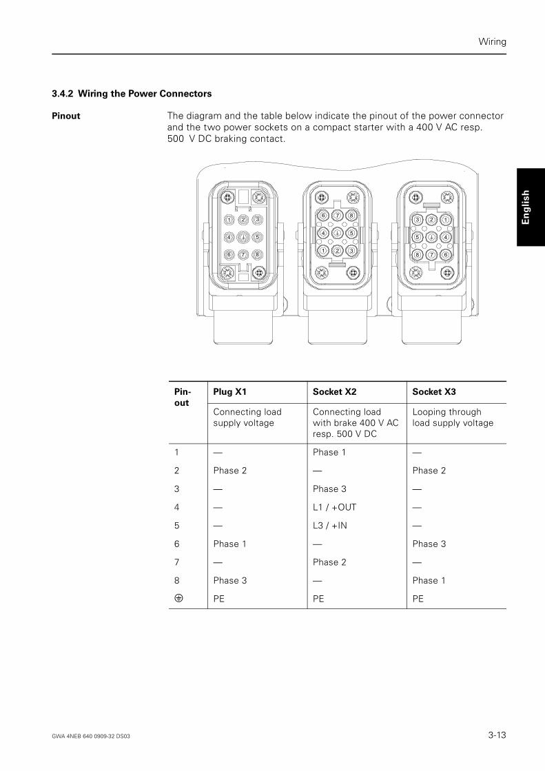
Pinout The diagram and the table below indicate the pinout of the power connector and the two power sockets on a compact starter with a 400 V AC resp. 500 V DC braking contact.
Pin-
out
Plug X1 Socket X2 Socket X3
Connecting load supply voltage
Connecting load with brake 400 V AC resp. 500 V DC
Looping through load supply voltage
1 — Phase 1 —
2 Phase 2 — Phase 2
3 — Phase 3 —
4 — L1 / +OUT —
5 — L3 / +IN —
6 Phase 1 — Phase 3
7 — Phase 2 —
8 Phase 3 — Phase 1
e PE PE PE
1 2 3
4 5
6 7 81 2 3
4 5
6 7 8123
45
678
GWA 4NEB 640 0909-32 DS03 3-13

Wiring
Power connectors The power connectors consist of the following components:
Installing and wiring
power connectors
Install the power connectors for a 400 V AC resp. 500 V DC compact starter with a braking contact as follows. Please note the wiring rules described in Chapter 3.1.
connector shell connector shell
socket insert
jacks contact pins
pin insert
Power socket
– for connecting load supply voltage Power connector
– for connecting the load with a brake– for looping through the load supply voltage
Step Procedure
Socket for X1 Connector for X2 Connector for X3
1 Feed the cable through the gland, the appropriately-sized sealing ring supplied and the con-nector shell.
2 Fasten the jacks to the cores
• for phases 1 to 3• for PE
Fasten the contact pins to the cores
• for phases 1 to 3• for the brake• for PE
Fasten the contact pins to the cores
• for phases 1 to 3• for PE
3 Press the jacks into the socket insert until they snap into place.
Press the contact pins into the pin insert until they snap into place.
4 Withdraw the cable sufficiently to be able to screw the socket or pin insert tightly inside the connector shell with the enclosed screws.
5 Screw the gland tight.
3-14 GWA 4NEB 640 0909-32 DS03

Wiring
Deu
tsch
En
gli
sh
3.4.3 Electrical Design
Suggested circuit
400 V AC brake
The following diagram shows you a way of controlling a pole-changing motor for two directions with a 400 V AC brake by two electronic compact starters.
Galvanic
isolation
An external isolating contactor must be fitted to ensure galvanic isolation from the power supply system!
Motor with separate windings and brake 400 V AC
6 2 8
X1
8 2 6 6 2 8 8 2 6
1 7 3 1 7 3
X1 X3
X2
4 5
1 W
1 V
1 U
2 U
2 V
2 W
P E
M3
X2
X3
L1
L2L3
K1
A1 A2
Galvanicisolation
GWA 4NEB 640 0909-32 DS03 3-15

Wiring
Suggested circuit
500 V DC brake
The following diagram shows you a way of controlling a motor with a 500 V DC brake by one electronic compact starter.
Galvanic
isolation
An external isolating contactor must be fitted to ensure galvanic isolation from the power supply system!
6 2 8
X1
8 2 6
1 7 3 5 4
1 W
1 V
1 U
P E
M3
X2
X3
L1
L2L3
K1
A1 A2
+ -
Motor with brake 500 V DC
Galvanicisolation
3-16 GWA 4NEB 640 0909-32 DS03

Wiring
Deu
tsch
En
gli
sh
3.5 Additional Inputs IN1 and IN2
Pinout The diagram and the table below indicate the pinout of M12 socket X4.
The M12 socket X4 is intended for the connection of 3-wire sensors (PNP) and contact-type signal transmitters. With the aid of a Y-connector (6ES7 194-1KA00-0XA0), 2 sensors can be connected at the same time.
The input signals on IN1 and IN2 are passed on over the bus as DI2 and DI3, respectively.
Pin M12 Socket X4
1 +
2 IN2
3 -
4 IN1
5 —
4
3 2
1
5
GWA 4NEB 640 0909-32 DS03 3-17

Wiring
3-18 GWA 4NEB 640 0909-32 DS03

Deu
tsch
En
gli
sh
4
Commissioning
Section Subject Page
4.1 Compact Starters DS2DI and RS2DI 4-2
4.1.1 Addressing 4-2
4.1.2 Before Commissioning 4-3
4.1.3 Operation 4-4
4.1.4 Diagnostics 4-5
4.2 Compact Starters EDS2DI and ERS2DI 4-8
4.2.1 Addressing 4-8
4.2.2 Before Commissioning 4-9
4.2.3 Operation 4-11
4.2.4 Diagnostics 4-13
GWA 4NEB 640 0909-32 DS03 4-1

Commissioning
Deutsch
English
4.1 Compact Starters DS2DI and RS2DI
4.1.1 Addressing
When? Addressing can be done before or after installation.
How? You can set the address
• with the addressing unit or the programming and service unit (PSG),• with the user program,• with the master (see handbook of the module concerned).
Addressing
with the PSG
Proceed as follows:
Valid addresses Valid addresses are 1 to 31. Use each address once only.
You can change the address of the compact starter up to a maximum of 15 times. Thereafter the last valid address is retained.
Step Procedure
1 Open the transparent cover in the top section of the compact starter.
2 Connect the addressing unit or the PSG with the addressing line 3RK1901-3HA01 to the addressing jack on the compact starter.
3 Set the desired address.
4-2 GWA 4NEB 640 0909-32 DS03

Commissioning
Deu
tsch
En
gli
sh
4.1.2 Before Commissioning
Set current Ie Before you commission the compact starter, you must set the current Ie for tripping the overload release.
External
short-circuit
protection
If the short-circuit current at the point at which the compact starter is installed is greater than the rated ultimate short-circuit breaking capacity Icu of the circuit-breaker (see table), you must provide external short-circuit pro-tection (fuse or circuit-breaker; see Catalog).
Overload release
test
You can test the overload release function.
Reversing starter
RS2EWhen switching over from right to left or back again, a stop interval of more than 200 milliseconds must be observed. This interval has to be set via the user program.
Step Procedure
1 Open the transparent cover in the top section of the compact starter.
2 Set the current Ie on the circuit-breaker scale with a screw-driver (see figure on page 1-3).
Ue Icu max
400 V AC 50 kA
440 V AC 10 kA
500 V AC 3 kA
Step Procedure
1 Open the transparent cover in the top section of the compact starter.
2 Reset the toggle switch from 0 to 1.
3 Insert a screwdriver in the test opening (see figure on page 1-3) and press it over to the left.The overload release function is working if the toggle switch is switched back from 1 to 0.
GWA 4NEB 640 0909-32 DS03 4-3

Commissioning
Deutsch
English
4.1.3 Operation
If overload release
trips
After an overload release trip during operation you must reset the circuit-breaker.
Disconnecting a load
from the power
system
You can disconnect a load from the electrical power system by resetting the toggle switch on the circuit-breaker from 1 to 0.
Safeguard against
accidental opening/
unauthorized
switching on
You can seal the transparent cover of the compact starter in order to safe-guard it against accidental opening, for example in order to prevent the over-load release current from being altered inadvertently.
You can prevent the compact starter from being switched on by unauthori-zed persons, by fitting the toggle switch of the circuit-breaker with a safety lock.
Step Procedure
1 Open the transparent cover in the top section of the compact starter.
2 Reset toggle switch from 0 to 1.
3 Check whether any switching contacts have been damaged as a result of a short-circuit (contactor contacts welded together).
4-4 GWA 4NEB 640 0909-32 DS03
Commissioning
Deu
tsch
En
gli
sh
4.1.4 Diagnostics
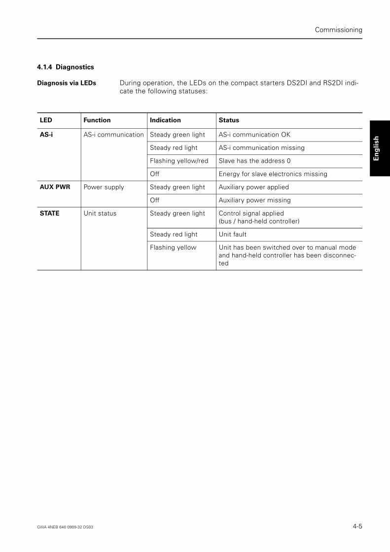
Diagnosis via LEDs During operation, the LEDs on the compact starters DS2DI and RS2DI indi-cate the following statuses:
LED Function Indication Status
AS-i AS-i communication Steady green light AS-i communication OK
Steady red light AS-i communication missing
Flashing yellow/red Slave has the address 0
Off Energy for slave electronics missing
AUX PWR Power supply Steady green light Auxiliary power applied
Off Auxiliary power missing
STATE Unit status Steady green light Control signal applied (bus / hand-held controller)
Steady red light Unit fault
Flashing yellow Unit has been switched over to manual mode and hand-held controller has been disconnec-ted
GWA 4NEB 640 0909-32 DS03 4-5

Commissioning
Deutsch
English
Diagnosis via the
user program
You can evaluate the input and output signals of the compact starters DS2DI and RS2DI in the user program. Please note that
• Output DO2 is only driven on versions with a braking contact.• The I/O assignment is in accordance with AS-i motor-starter profile 7D.
Digital inputs
Input signals Status Description
DI0 "ready" 0 Unit not ready / fault Manual mode
• Unit has been switched over locally to manual mode -> switch over to automatic on the hand-held controller
Overload /Short-circuit release
• Circuit-breaker reclosing after a cooling-off period
FAULT signal
• Contactor coil faulty • Contactor contacts welded together• Output driver faulty -> inspect contactor• Simultaneous activation of clockwise and
anticlockwise rotation -> inspect user pro-gram
1 Unit ready / automatic —
DI1 "running" 0 Contactor off —
1 Contactor on —
DI2 "special
information 1"
0 No input signal on IN1 —
1 Input signal on IN1 —
DI3 "special
information 2"
0 No input signal on IN2 —
1 Input signal on IN2 —
4-6 GWA 4NEB 640 0909-32 DS03

Commissioning
Deu
tsch
En
gli
sh
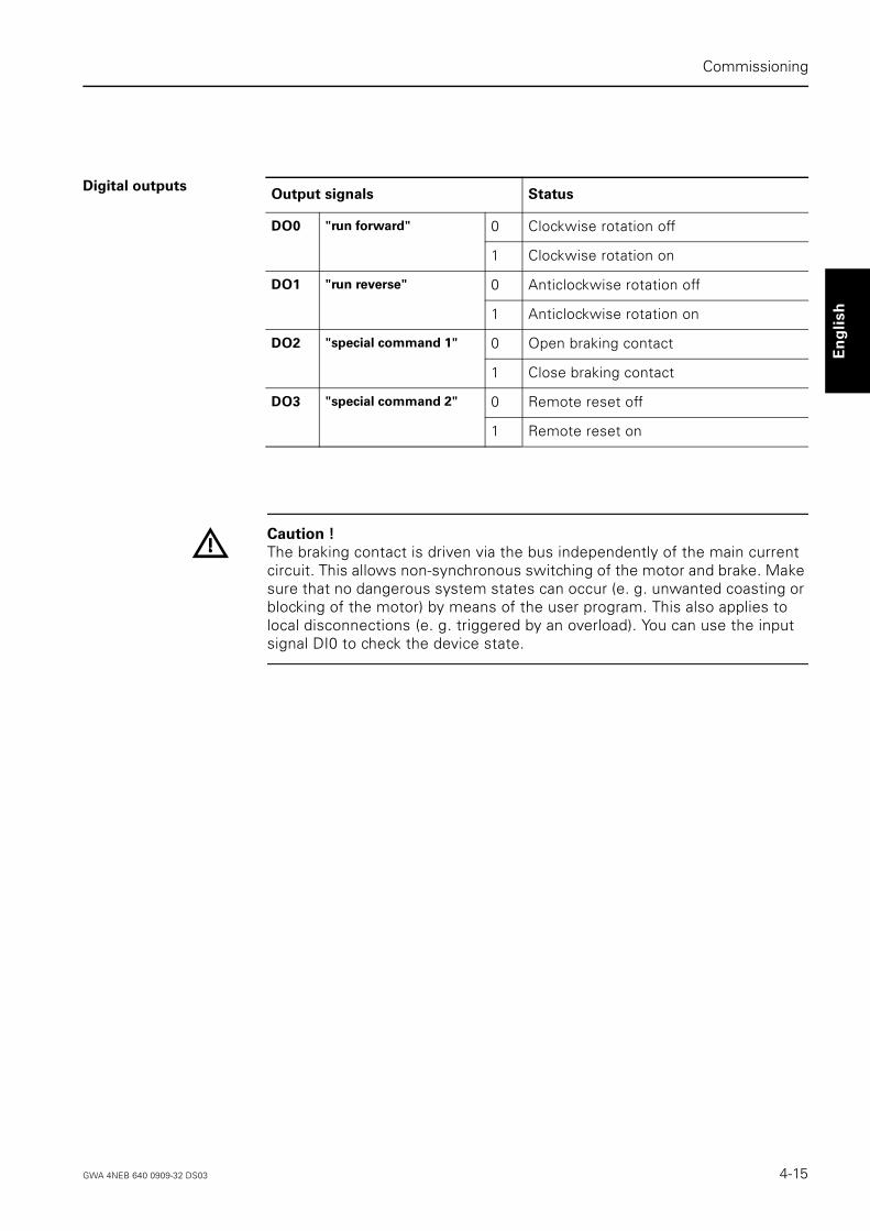
Digital outputs
Caution !
The braking contact is driven via the bus independently of the main current circuit. This allows non-synchronous switching of the motor and brake. Make sure that no dangerous system states can occur (e. g. unwanted coasting or blocking of the motor) by means of the user program. This also applies to local disconnections (e. g. triggered by an overload). You can use the input signal DI0 to check the device state.
Output signals Status
DO0 "run forward" 0 Clockwise rotation off
1 Clockwise rotation on
DO1 "run reverse" 0 Anticlockwise rotation off
1 Clockwise rotation on
DO2 "special command 1" 0 Open braking contact
1 Close braking contact
DO3 "special command 2" 0 —
1 —
GWA 4NEB 640 0909-32 DS03 4-7

Commissioning
Deutsch
English
4.2 Compact Starters EDS2DI and ERS2DI
4.2.1 Addressing
When? Addressing can be done before or after installation.
How? You can set the address
• with the addressing unit or the programming and service unit (PSG),• with the user program,• with the master (see handbook of the module concerned).
Addressing
with the PSG
Proceed as follows:
Valid addresses Valid addresses are 1 to 31. Use each address once only.
You can change the address of the compact starter up to a maximum of 15 times. Thereafter the last valid address is retained.
Step Procedure
1 Open the transparent cover in the top section of the compact starter.
2 Connect the addressing unit or the PSG with the addressing line 3RK1901-3HA01 to the addressing jack on the compact starter.
3 Set the desired address.
4-8 GWA 4NEB 640 0909-32 DS03

Commissioning
Deu
tsch
En
gli
sh
4.2.2 Before Commissioning
Set current Ie Set current Ie for overload tripping before commissioning the electronic com-pact starter EDS2DI and ERS2DI. The setting is made with 2 rotary encoder switches with 8 or 10 switch positions (see figure on page 1-4). The set value in each case is derived from the sum of the two set values.
Set values The set values together with their position on the rotary encoder switch are given in the table below.
Example If you want to set a current of 1.28 A, turn switch 1 to position 3 and switch 2 to position 4.
Position of the
rotary encoder
switch
Power range 1
0.6 - 2.18 A
Power range 2
2.0 - 5.95 A
Switch 1 Switch 2 Switch 1 Switch 2
0 0.6 0.00 2.0 0.00
1 0.8 0.02 2.5 0.05
2 1.0 0.04 3.0 0.10
3 1.2 0.06 3.5 0.15
4 1.4 0.08 4.0 0.20
5 1.6 0.10 4.5 0.25
6 1.8 0.12 5.0 0.30
7 2.0 0.14 5.5 0.35
8 — 0.16 — 0.40
9 — 0.18 — 0.45
Power range 1: 1.28 A = 1.2 A + 0.08 A
Switch 1 Position 3
Switch 2 Position 4
GWA 4NEB 640 0909-32 DS03 4-9

Commissioning
Deutsch
English
Electronic
overload protection
You can set the overload protection mode with the tripping REMOTE/LOCAL rotary encoder switch on the electronic compact starter EDS2DI and ERS2DI.
In the user program you can define the response to the signal "FAULT /release signal" (Input DI0) when the rotary encoder switch is in position REMOTE.
Caution !
Direct shutdown of the device if a release signal is received is disabled if the rotary encoder switch is in the tripping REMOTE position.
In the user program, define a suitable response (usually shutdown of the load circuit) for a signal received at input DI0.
Rotary
encoder
switch
position
Overload
protection
Response
Tripping
REMOTE
Control via the bus
Depending on the settings in the user program:
• Operation continued inspite of release signal or
• Remote shutdown (= overload release)
Tripping
LOCAL
Local control • Direct shutdown (= overload release)
4-10 GWA 4NEB 640 0909-32 DS03

Commissioning
Deu
tsch
En
gli
sh
Overload release
test
You can perform an overload release test either in the initial state or in ope-rating mode. An internal program checks the overload and current flow acquisition.
Safeguard against
accidental opening
You can apply a lead seal or place a lock on the transparent cover of the com-pact starter EDS2DI and ERS2DI to prevent unauthorized setting of the rotary encoder switch, for example.
4.2.3 Operation
Remote reset Remote reset causes the following:
• If the rotary encoder switch is in position tripping LOCAL: Resets overload release as soon as the motor model has fallen below the release threshold.
• If the rotary encoder switch is in position tripping LOCAL or tripping REMOTE:Resets a FAULT signal if the cause of the fault has been remedied.
Local reset If you press the TEST/RESET button during a local reset, various responses are triggered depending on how long the button is depressed (see the following table).
Step Procedure Description READY
LED
OVERLOAD
LED
FAULT
LED
1 Open the transparent cover in the top section of the compact starter.
On — —
2 Press the TEST/RESET button for at least 2 s.
Test runs for approx. 10 s.Bus control is disabled.
On Flashes fast —
a) Test successful On Flashes slowly
—
3a Press theTEST/RESET button again.
Bus control enabled again. On Off —
b) Fault during test Off Flashes slowly
On
3b Remedy the cause of the fault.
4 Press theTEST/RESET button again for at least 2 s.
Test is restarted. On Flashes fast —
a) Test successful:See step 3 for how to continue procedure.
On Flashes slowly
—
GWA 4NEB 640 0909-32 DS03 4-11

Commissioning
Deutsch
English
Reset after signal
"FAULT/release
signal" (Input DI0)
After a release signal (device continues operation) resp. overload release (device is shut down) the OVERLOAD LED lights up. After a FAULT signal (device is shut down) the FAULT LED lights up. You can reset the OVER-LOAD resp. FAULT display and the DI0 signal with a local or remote reset in which case the LEDs goes out.
Communication
failure
If communication fails, the circuit outputs are reset after approx. 100 ms. Restart is automatic.
Note
If the 24 V DC supply voltage for electronic motor starters is interrupted for lon-ger than 5 seconds, a waiting period of t > 50 s for normal operation must be observed before switching back on.
Rotary
encoder
switch
position
Reset Procedure
Tripping
REMOTE
Local reset • Press the RESET/RESET button for less than 2 s: – A pending FAULT signal is reset if the cause of the fault has been
remedied.
• Press the TEST/RESET button for more than 2 s:– Fast discharge of the motor model, i.e. the motor model is reset without
a delay,– Device self-test is triggered. Press the TEST/RESET button again as soon
as the READY LED lights up again.
Auto reset The release signal is reset automatically as soon as the motor model is below the release threshold again.
Tripping
LOCAL
Local reset • Press the RESET/RESET button for less than 2 s:
– The release signal is reset as soon as the motor model is below the release threshold again,
– A pending FAULT signal is reset if the cause of the fault has been remedied.
• Press the TEST/RESET button for more than 2 s:
– Fast discharge of the motor model, i.e. the motor model is reset without a delay,
– Device self-test is triggered. Press the TEST/RESET button again as soon as the READY LED lights up again.
Remote
Reset
In the user program set output DO3 to "1" and then to "0" again.
4-12 GWA 4NEB 640 0909-32 DS03

Commissioning
Deu
tsch
En
gli
sh
4.2.4 Diagnostics
Diagnosis via LEDs During operation, the LEDs on the compact starters EDS2DI and ERS2DI indicate the following statuses:
LED Function Indication Status
AS-i AS-i communication Steady green light AS-i communication OK
Steady red light AS-i communication missing
Flashing yellow/red Slave has the address 0
Off Energy for slave electronics missing
AUX PWR Power supply Steady yellow light Auxiliary power applied
Off Auxiliary power missing
STATE Unit status Steady green light Control signal applied (bus/hand-held controller)
Flashing yellow Unit has been switched over to manual mode and hand-held controller has been disconnected
READY Initial state Steady green light Device ready for operation
RUN Operating state Steady yellow light Main circuit on
if current flow > 20 % In
FAULT Fault Steady red light Main circuit off, e.g. after
• Failure of two phases• Motor connector pulled out• Supply voltage dip (< 18 V)• Simultaneous activation of clockwise and
anticlockwise rotation
OVERLOAD Overcurrent signal Flashing red Main circuit on
Overload release test Flashing red Flashes quicklyFlashes slowly
Main circuit off
Test runningTest completed
Overload release Steady red light Main circuit off
Rotary encoder switch in position• Tripping LOCAL: Direct shutdown• Tripping REMOTE: Remote shutdown
if the relevant settings have been made in the user program
Release signal Steady red light Main circuit on
• Rotary encoder switch in position Trip-ping REMOTE: Operation is continued if the relevant settings have been made in the user program.
GWA 4NEB 640 0909-32 DS03 4-13
Commissioning
Deutsch
English
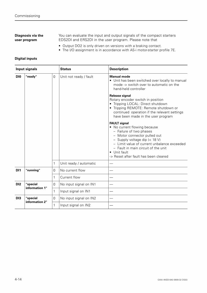
Diagnosis via the
user program
You can evaluate the input and output signals of the compact starters EDS2DI and ERS2DI in the user program. Please note that
• Output DO2 is only driven on versions with a braking contact.• The I/O assignment is in accordance with AS-i motor-starter profile 7E.
Digital inputs
Input signals Status Description
DI0 "ready" 0 Unit not ready / fault Manual mode
• Unit has been switched over locally to manual mode -> switch over to automatic on the hand-held controller
Release signal
Rotary encoder switch in position • Tripping LOCAL: Direct shutdown• Tripping REMOTE: Remote shutdown or
continued operation if the relevant settings have been made in the user program
FAULT signal
• No current flowing because– Failure of two phases– Motor connector pulled out– Supply voltage dip (< 18 V)– Limit value of current unbalance exceeded– Fault in main circuit of the unit
• Unit fault-> Reset after fault has been cleared
1 Unit ready / automatic —
DI1 "running" 0 No current flow —
1 Current flow —
DI2 "special
information 1"
0 No input signal on IN1 —
1 Input signal on IN1 —
DI3 "special
information 2"
0 No input signal on IN2 —
1 Input signal on IN2 —
4-14 GWA 4NEB 640 0909-32 DS03
Commissioning
Deu
tsch
En
gli
sh
Digital outputs
Caution !
The braking contact is driven via the bus independently of the main current circuit. This allows non-synchronous switching of the motor and brake. Make sure that no dangerous system states can occur (e. g. unwanted coasting or blocking of the motor) by means of the user program. This also applies to local disconnections (e. g. triggered by an overload). You can use the input signal DI0 to check the device state.
Output signals Status
DO0 "run forward" 0 Clockwise rotation off
1 Clockwise rotation on
DO1 "run reverse" 0 Anticlockwise rotation off
1 Anticlockwise rotation on
DO2 "special command 1" 0 Open braking contact
1 Close braking contact
DO3 "special command 2" 0 Remote reset off
1 Remote reset on
GWA 4NEB 640 0909-32 DS03 4-15

Commissioning
Deutsch
English
4-16 GWA 4NEB 640 0909-32 DS03
Deu
tsch
En
gli
sh
5
Hand-held Controller
Section Subject Page
5.1 Functions and View 5-2
5.2 Operation 5-3
5.3 LEDs 5-4
5.4 Buttons 5-5
GWA 4NEB 640 0909-32 DS03 5-1

Hand-held Controller
Deutsch
English
5.1 Functions and View
Functions You can use the hand-held controller to operate the compact starter indepen-dently in the field when auxiliary power is applied:
• Before commissioning the AS-i bus and the PLC in order to test the motor,• In order to operate the system in manual mode if the PLC or the bus system
fails,• When operating a PLC or bus for autonomous local operator control,• During normal operation in order to test the outputs (diagnosis/monitoring).
View
Function modes You can operate the hand-held controller in "jogging mode" and "continuous mode". In manual mode, the functions of the left and right buttons differ depending on this setting.
Caution !
In manual mode, the brake contact is activated by the hand-held controller syn-chronously with activation by the main circuit. Keep in mind that the brake remains active in manual operation when the unit is interrupted (e.g. overload trip or fault condition). To avoid dangerous system states (e. g. unwanted coasting of the motor), we recommend using the manual control in "jogging mode".
Automatic mode
Manual mode
power
stand by
left right
remote
local
3RK1 902-0AM00
5-2 GWA 4NEB 640 0909-32 DS03
Hand-held Controller
Deu
tsch
En
gli
sh
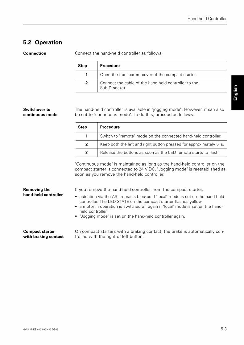
5.2 Operation
Connection Connect the hand-held controller as follows:
Switchover to
continuous mode
The hand-held controller is available in "jogging mode". However, it can also be set to "continuous mode". To do this, proceed as follows:
"Continuous mode" is maintained as long as the hand-held controller on the compact starter is connected to 24 V DC. "Jogging mode" is reestablished as soon as you remove the hand-held controller.
Removing the
hand-held controller
If you remove the hand-held controller from the compact starter,
• actuation via the AS-i remains blocked if "local" mode is set on the hand-held controller. The LED STATE on the compact starter flashes yellow.
• a motor in operation is switched off again if "local" mode is set on the hand-held controller.
• "Jogging mode" is set on the hand-held controller again.
Compact starter
with braking contact
On compact starters with a braking contact, the brake is automatically con-trolled with the right or left button.
Step Procedure
1 Open the transparent cover of the compact starter.
2 Connect the cable of the hand-held controller to the Sub-D socket.
Step Procedure
1 Switch to "remote" mode on the connected hand-held controller.
2 Keep both the left and right button pressed for approximately 5 s.
3 Release the buttons as soon as the LED remote starts to flash.
GWA 4NEB 640 0909-32 DS03 5-3

Hand-held Controller
Deutsch
English
5.3 LEDs
Monitoring You can monitor the functions of the compact starter via the LEDs on the hand-held controller:
LED Lights up when ... Goes out when ...
Power Auxiliary power is supplied. No auxiliary power is supplied.
Standby Auxiliary power is supplied. Remote or local is pressed on the hand-held controller.
Right The direct starter is switched on.
The direct starter is switched off.
The reversing starter activates the clockwise direction.
• The reversing starter activates the anticlockwise direction.
• The reversing starter is switched off.
Left The reversing starter activates the anticlockwise direction.
• The reversing starter activates the clockwise direction
• The reversing starter is switched off
Remote Automatic mode is switched on.
The hand-held controller is switched to manual mode.
Local Manual mode is switched on. The hand-held controller is switched to automatic mode.
5-4 GWA 4NEB 640 0909-32 DS03

Hand-held Controller
Deu
tsch
En
gli
sh
5.4 Buttons
Remote button You can set the compact starter to automatic mode with the remote button. In this mode you can monitor the status of the bus control.
The LED indicates
• on a direct starter whether the bus is controlled,• on a reversing starter, the direction currently activated:
Clockwise (LED right) or anticlockwise (LED left).
Local button With the local button you can set the compact starter to manual mode. Activation via AS-i is blocked in this mode!
If you switch from "remote" to "local", an active motor is switched off.
If you disconnect the hand-held controller,
• "local" mode is maintained, i.e. activation via AS-i remains blocked. The LED STATE on the compact starter flashes yellow.
• a motor in operation is switched off.
Right-/left button The table below shows the functions of the right and left button in manual mode ("local" button) in relation to the function mode of the hand-held con-troller:
Function
mode of
hand-held
controller
Manual mode
Jogging
mode
The compact starter remains switched on while you keep the right or left button (on the reversing starter) pressed.
Continuous
mode
You can effect the following actions:
• With a direct-on-line starter
– Switch on the compact starter by pressing the ”Right” button once,
– Switch off the compact starter by pressing the ”Right” button again or by pressing the ”Left” button.
• With a reversing starter
– Activate the ”left” or ”right” direction of rotation by pressing the appropriate button,
– Switch off the compact starter by pressing the same button again,
– Reverse the direction of rotation directly.
GWA 4NEB 640 0909-32 DS03 5-5

Hand-held Controller
Deutsch
English
5-6 GWA 4NEB 640 0909-32 DS03

Deu
tsch
En
gli
sh
6
Technical Data
Section Subject Page
6.1 Compact Starter Data 6-2
6.2 Voltages and Currents 6-3
6.3 Braking Current Circuit 6-4
6.4 Additional Inputs IN1 and IN2 6-4
6.5 Data pertaining to the Compact Starters DS2DI and RS2DI
6-5
6.6 Data pertaining to the Compact Starters EDS2DI and ERS2DI
6-6
6.7 Shipping and Storage Conditions 6-7
6.8 Mechanical and Climatic Environment Conditions 6-8
6.9 Electromagnetic Compatibility 6-9
GWA 4NEB 640 0909-32 DS03 6-1

Technical Data
Deutsch
English
6.1 Compact Starter Data
Note
The degree of protection IP 65 is only warranted when the compact starter is completely closed. Therefore: Seal off any terminal connections which are not required with screw caps.
IO-Code/ID-Code Compact starter DS2DI and RS2DI Compact starter EDS2DI and ERS2DI
7D7E
Dimensions W x H x D (mm) 120 x 265 x 134
Weight Direct-on-line starter DSReversing starter RSDirect-on-line starter EDSReversing starter ERSMounting plate
1.5 kg1.9 kg1.5 kg1.6 kg0.1 kg
Assignment type Type 1 up to Irated ≤ 12 A IEC 60947-4-1, DIN VDE 0660, Part 102
Type 2 up to Irated ≤ 1.6 A (does not apply to compact starters EDS2DI and ERS2DI)
Pollution severity 3 IEC 60664 (IEC 61131)
Safety class I IEC 60536 (VDE 0106, Part 1)
Degree of protection IP 65 IEC 60529
• Protection against the ingress of dust and complete protection against elec-tric shock
• Protection against water jets from nozzles which are aimed at the casing from all directions. (There must be no harmful effects from the water.)
Insulation strength Circuits with a rated voltage Ue
to other circuits or to ground
Test voltage in accordance with IEC 61131, Part 2
0 V < Ue ≤ 50 V 500 V DC
300 V < Ue ≤ 600 V 2.6 kV DC to ground
6-2 GWA 4NEB 640 0909-32 DS03

Technical Data
Deu
tsch
En
gli
sh
6.2 Voltages and Currents
Voltages Energy for slave electronics (in accordance with AS-i specification)Reverse polarity protection
26.5 to 31.6 V DC
yes
Auxiliary power
Reverse polarity protection
24 V DC, tolerance range 20.4 to 28.8 V DCyes
Braking voltage• compact starters DS2DI and RS2DI • compact starters EDS2DI and ERS2DI
Reverse polarity protection
24 V DC, 500 V DC24 V DC, 400 V AC, 500 V DC
yes
Safe isolation between main circuit and auxiliary circuit to IEC 60947-1
400 V
Currents Aggregate current of compact starters • at 55 ° C
- with 2.5 mm2 connection - with 4.0 mm2 connection
• at 40 ° C - with 2.5 mm2 connection - with 4.0 mm2 connection
20 A30 A
25 A35 A
Power input• Intrinsic consumption • with sensor supply• from auxiliary power
(without hand-held controller)
approx. 70 mAmax. 270 mAapprox. 170 mA
Minimum tripping current if a phase fails (= 100% current unbalance)
0.85 x Ie
Main circuit Rated operating voltage Ue• to CSA and UL• DS2E and RS2E compact starters:
according to IEC 60947-4-1• EDS2 E and ERS2E compact starters:
according to IEC 60947-4-2
up to 600 V AC 500 V AC, tolerance up to 575 V AC
Network configurations:In grounded star-type networks up to 277 / 480 V AC, in ungrounded or single-ended networks up to 277 V AC. Safe isolation between main voltage and control voltage: max. voltage to ground 300 V AC, 200 V DC.
Rated insulation voltage Ui 690 V AC
Rated impulse strength Uimp• compact starters DS2DI and RS2DI • compact starters EDS2DI and ERS2DI
6 kV4 kV
Rated frequency 50/60 Hz
GWA 4NEB 640 0909-32 DS03 6-3

Technical Data
Deutsch
English
Caution
Large EMC faults can occur as a result of three-phase motors being opera-ted when connected in star formation (particularly when < 1 kW). Faults above the IEC limit values can lead to impairment of function or failure of the electronics.We recommend using motors featuring EMC protective circuits in the case of high EMC faults. (Exception: Electronic starters must not be operated with an EMC protective circuit). The best filter effect is achieved using 3-phase RC interference suppression modules. Varistor interference sup-pression modules should not be used, as these do not filter out rapid transi-ents to a sufficient extent.
6.3 Braking Current Circuit
6.4 Additional Inputs IN1 and IN2
Version with
a 24 V DC
braking contact
Utilization categoryto VDE 0660, Part 102 and IEC 60947-4.1
DC-13
Max. permissible output of the brake coil 70 W
Rated operational current Ie 3 A
Version with
a 400 V AC
braking contact
Utilization categoryto VDE 0660, Part 102 and IEC 60947-4.1
AC-15
Max. permissible output of the brake coil 200 VA
Rated operational current Ie 0.5 A
Version with
a 500 V DC
braking contact
Utilization categoryto VDE 0660, Part 102 and IEC 60947-4.1
DC-13
Max. permissible output of the brake coil 100 W
Rated operational current Ie 0.2 A
Pinout 1 = +2 = IN2 3 = -4 = IN1
Digital inputs For signal "0" Iin ≤ 1,5 mA
For signal "1" Uin Iin
≥ 10 V≥ 6 mA
Sensor supply
(short-circuit and
overload-proof)
Voltage range Uout 20 V to 30 V DC
Current carrying capacity Iout 200 mA
6-4 GWA 4NEB 640 0909-32 DS03

Technical Data
Deu
tsch
En
gli
sh
6.5 Data pertaining to the Compact Starters DS2DI and RS2DI
Switching cycles
Circuit-breaker Tripping class Class 10
Max. rated current 12 A
Adjustment ranges• Thermal overload release• Undelayed overcurrent release
0.14-0.2 A to 9-12 A12 x Irated (fixed)
Rated ultimate short-circuit breaking capacity up to Irated = 12 A
50 kA
Mechanical life ≥ 100,000 switching cycles
Contactor Utilization category to VDE 0660, Part 102 and IEC 60947-4.1
AC-2, AC-3
Rated operating current Ie 12 A
Max. permissible switching rate at motor starting time ta = 0.1 s and 50% relative ON period
≤ 80/h
Mechanical life ≥ 10 Mill. switching cycles
Operating deay of auxiliary contact (including input delay of module)• From 0 to 1• From 1 to 0
29 to 59 ms26 to 34 ms
switc
hing
cyc
les
at 4
00 V
Permissible output
Breaking current
Rated operating current
of three phase motors at 400 V
PN =
Ia = Ie =
GWA 4NEB 640 0909-32 DS03 6-5
Technical Data
Deutsch
English
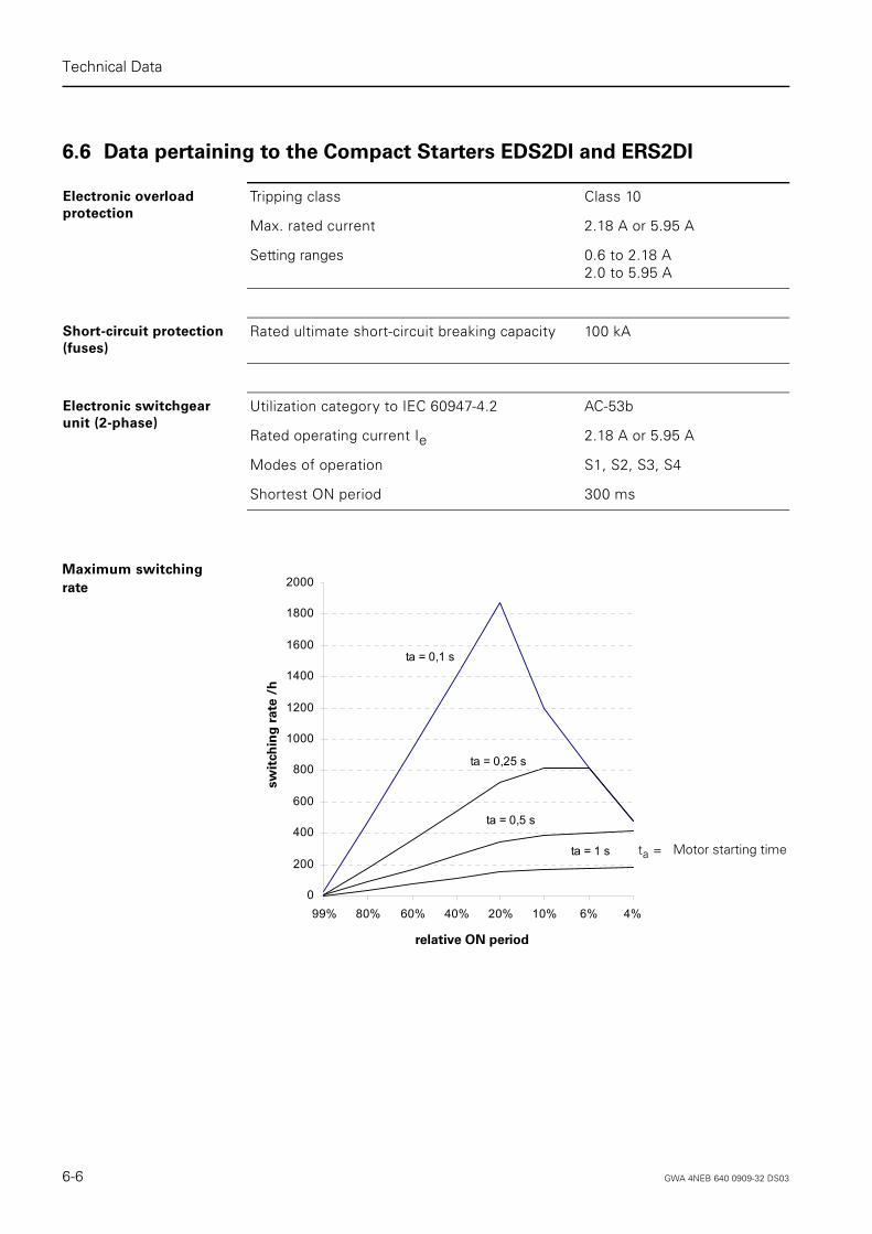
6.6 Data pertaining to the Compact Starters EDS2DI and ERS2DI
Maximum switching
rate
Electronic overload
protection
Tripping class Class 10
Max. rated current 2.18 A or 5.95 A
Setting ranges 0.6 to 2.18 A2.0 to 5.95 A
Short-circuit protection
(fuses)
Rated ultimate short-circuit breaking capacity 100 kA
Electronic switchgear
unit (2-phase)
Utilization category to IEC 60947-4.2 AC-53b
Rated operating current Ie 2.18 A or 5.95 A
Modes of operation S1, S2, S3, S4
Shortest ON period 300 ms
0
200
400
600
800
1000
1200
1400
1600
1800
2000
99% 80% 60% 40% 20% 10% 6% 4%
relative Einschaltdauer
Scha
ltung
en /h
ta = 0,1 s
ta = 0,25 s
ta = 0,5 s
ta = 1 s Motor starting timeta =
relative ON period
sw
itch
ing
rate
/h
6-6 GWA 4NEB 640 0909-32 DS03

Technical Data
Deu
tsch
En
gli
sh
6.7 Shipping and Storage Conditions
Shipping and
storage conditions
The AS-i compact starter surpasses the requirements of IEC 61131, Part 2, with regard to shipping and storage conditions. The following details apply to modules that are shipped and stored in their original packing.
Type of condition Admissible range
Free fall 0.4 m
Temperature from -40 °C to +70 °C
Temperature variation 20 K/h
Air pressure from 1,080 to 660 hPa (corresponds to an altitude of -1,000 to 3,500 m)
Relative humidity from 5 to 95%, without condensation
GWA 4NEB 640 0909-32 DS03 6-7

Technical Data
Deutsch
English
6.8 Mechanical and Climatic Environment Conditions
Mechanical
environment
conditions
Oscillation test to IEC 60068, Part 2-6 (Sine)
• Oscillation type: frequency sweeps with a rate of change of 1 octave per minute
- 10 Hz ≤ f ≤ 58 Hz constant amplitude: 0.15 mm
- 58 Hz ≤ f ≤ 150 Hz constant acceleration: 2 g
• Oscillation time: 10 frequency sweeps per axis in all of the three perpendicular axes
Shock test to IEC 60068, Part 2-27
• Type of shock:• Force of shock:• Direction of shock:
Half sine 15 g peak value, 11 ms duration3 shocks per +/– direction in all of the three perpen-dicular axes
Climatical
environment
conditions
Temperature From -25 to 55 °C All installation positions
Temperature variation 10 K/h
Permissible rated current 100% at -25 °C ≤ Tenv < 40 °C87% at 40 °C ≤ Tenv ≤ 55 °C
Relative humidity From 5 to 100%
Air pressure From 1080 to 795 hPa Corresponds to an alti-tude of -1,000 to 2,000 m
Contaminant concentration SO2 : < 0.5 ppm rel. humidity < 60%, no moisture condensation
Test:10 ppm; 4 days
H2 S: < 0.1 ppm rel. humidity < 60%,no moisture condensation
1 ppm; 4 days
6-8 GWA 4NEB 640 0909-32 DS03

Technical Data
Deu
tsch
En
gli
sh
6.9 Electromagnetic Compatibility
Definition Electromagnetic compatibility is the ability of an electric device to function satisfactorily in its electromagnetic environment without interfering with this environment.
The AS-i compact starter also meets the requirements, among others, of the EMC Act of the European Community.
.
Pulse-shaped
interference
Electrostatic discharge in accordance with IEC 60801-2(DIN VDE 0843 Part 2)
Tested with8 kV4 kV
Corresponds to severity3 (air discharge)2 (contact discharge)
Burst impulse in accordance with IEC 60801-4 (DIN VDE 0843 Part 4)
2 kV (supply line)2 kV (signal line)
3
Surge in accordance with IEC 60801-5 (DIN VDE 0839 Part 10)
3
• Asymmetrical connection 2 kV (supply line)2 kV (signal line/data line)
• Symmetrical connection 1 kV (supply line)1 kV (signal line/data line)
Sine-shaped
interference
RF radiation to EN 50140 (corresponds to IEC 60801-3)
Electromagnetic RF field
• Amplitude-modulated: 80 to 1000 MHz 10 V/m
80% AM (1 kHz)
• Pulse-modulated: 900 ± 5 MHz 50% ED 200 Hz repetition frequency
RF coupling to EN 50141 (corresponds to IEC 60801-6)
0.15 to 80 MHz 10 Vrms unmodulated
80% AM (1kHz)
150 Ω source impedance
Emission of
radio interference
Frequency Emitted interference in accordance with EN 55011: Limit Value Class A, Group 1 (measured at a distance of 30 m)
• From 20 to 230 MHz < 30 dB (μV/m)Q
• From 230 to 1,000 MHz < 37 dB (μV/m)Q
GWA 4NEB 640 0909-32 DS03 6-9

Technical Data
Deutsch
English
6-10 GWA 4NEB 640 0909-32 DS03

Deu
tsch
En
gli
sh
7
SIGUARD Safety Integrated
Section Subject Page
7.1 Suggested Circuits 7-2
7.1.1 Safety Category 1 (EN 954-1) 7-2
7.1.2 Safety Category 2 (EN 954-1) 7-2
7.1.3 Safety Category 3 (EN 954-1) 7-3
7.1.4 Safety Category 4 (EN 954-1) 7-3
GWA 4NEB 640 0909-32 DS03 7-1

SIGUARD Safety Integrated
Deutsch
English
7.1 Suggested Circuits
7.1.1 Safety Category 1 (EN 954-1)
7.1.2 Safety Category 2 (EN 954-1)
M
AC 400V
+ -+ -
-X1
-X2
-X3
IN0
IN1
M
-X1
-X2
-X3
Out 0 Out 0 IN0
IN1
IN0
IN1
M
-X1
-X2
-X3
Out 0
AS
-Inte
rfac
e
DC
24
V lo
ad
Emergencytrip
+ .- ..... +. -
Reset
AC 400V
+ -+ -
IN0
IN1
Out 0
M M M
-X1 -X1 -X1
-X2 -X2 -X2
-X3-X3-X3
IN0
IN1
Out 0 Out 0 IN0
IN1
RunOn
I>
1
1
AS
-Inte
rfac
e
DC
24
V lo
ad
Safety relay,e.g.SIGUARD3TK28
Emergencytrip 1
Emergencytrip 2
7-2 GWA 4NEB 640 0909-32 DS03

SIGUARD Safety Integrated
Deu
tsch
En
gli
sh
7.1.3 Safety Category 3 (EN 954-1)
7.1.4 Safety Category 4 (EN 954-1)
21
2 Reset
AC 400V
+ -+ -
1
IN0
IN1
Out 0
M M M
-X1 -X1 -X1
-X2 -X2 -X2
-X3-X3-X3
IN0
IN1
Out 0 Out 0 IN0
IN1
RunOn
I>
AS
-Inte
rfac
e
DC
24
V lo
ad
Safety relay,e.g.SIGUARD3TK28
Emergencytrip 1
Emergencytrip 2
21
2 Reset
AC 400V
+ -+ -
1
IN0
IN1
Out 0
M M M
-X1 -X1 -X1
-X2 -X2 -X2
-X3-X3-X3
IN0
IN1
Out 0 Out 0 IN0
IN1
RunOn
I>
AS
-Inte
rfac
e
DC
24
V lo
ad
Safety relay,e.g.SIGUARD3TK28
Emergencytrip
GWA 4NEB 640 0909-32 DS03 7-3

SIGUARD Safety Integrated
Deutsch
English
7-4 GWA 4NEB 640 0909-32 DS03

Deu
tsch
En
gli
sh
A
Selection Help
Section Subject Page
A.1 Application Examples A-2
A.2 Motor List A-3
GWA 4NEB 640 0909-32 DS03 A-1

Selection Help
Deutsch
English
A.1 Application Examples
The table below contains various applications together with the type and number of AS-i compact starters that you need for each application.You can actuate both pole-changing motors and motors with separate windings.
Notes 1) The two speeds must be mutually interlocked in the user program with the feedback contactor of the other starter.
2) see 1), but in addition the output brake of one starter must remain set during switchover and activation of the other starter.
3) This version is suitable if you want to loop the 24 V DC braking voltage through to the next drive. The 24 V DC braking voltage cannot be looped through via a compact controller without braking contact.
Applications Direct-on-line
starter
Reversing starter Direct-on-line
starter with
braking contact
Reversing starter
with braking
contact
With-
out
brake
One dir. of rotationOne speed
1
Two dir. of rotationOne speed
1
One dir. of rotationTwo speeds
2 1)
Two dir. of rotationTwo speeds
2 1)
With
brake
One dir. of rotationOne speed
1
Two dir. of rotationOne speed
1
One dir. of rotationTwo speeds
1 2) 1 2)
2 3)
Two dir. of rotationTwo speeds
1 2) 1 2)
2 3)
A-2 GWA 4NEB 640 0909-32 DS03

Selection Help
Deu
tsch
En
gli
sh
A.2 Motor List
Motor List The following tables contain the operating values of squirrel-cage motors of basic design. Source: Siemens Three-Phase AC Low-Voltage Motors Catalog.
Speed
3000 rpm
two-pole
Rated power
kW
Rated speed
rpm
Efficiency
%
Power factor
cos ϕRated current
A
50 Hz
400 V
0.18 2680 60 0.83 0.52
0..25 2725 64 0.82 0.69
0.37 2750 67 0.80 1.00
0.55 2790 71 0.81 1.38
0.75 2850 74 0.83 1.76
1.1 2835 76 0.84 2.45
1.5 2860 78 0.82 3.40
2.2 2850 80 0.85 4.65
3 2895 83 0.86 6.10
4 2895 85 0.87 7.80
5.5 2910 84 0.84 11.30
Speed
1500 rpm
four-pole
50 Hz
400 V
0.18 1315 59 0.76 0.58
0.25 1325 61 0.73 0.81
0.35 1375 66 0.77 1.05
0.55 1395 71 0.79 1.42
0.75 1395 74 0.79 1.86
1.1 1410 74 0.81 2.65
1.5 1410 74 0.81 3.60
2.2 1420 78 0.78 5.20
3 1430 80 0.80 6.80
4 1435 83 0.79 9.00
5.5 1450 86 0.81 11.40
GWA 4NEB 640 0909-32 DS03 A-3

Selection Help
Deutsch
English
Speed
1000 rpm
six-pole
Rated power
kW
Rated speed
rpm
Efficiency
%
Power factor
cos ϕRated current
A
50 Hz
400 V
0.18 830 53 0.71 0.69
0.25 825 59 0.74 0.83
0.35 910 62 0.72 1.19
0.55 900 65 0.73 1.67
0.75 895 67 0.77 2.10
1.1 900 71 0.75 3.00
1.5 930 72 0.75 4.00
2.2 945 76 0.72 5.80
3 945 70 0.75 7.30
4 940 79 0.75 9.70
Speed
750 rpm
eight-pole
50 Hz
400 V
0.12 655 51 0.59 0.58
0.18 675 51 0.66 0.78
0.25 670 52 0.62 1.12
0.35 655 61 0.76 1.16
0.55 650 65 0.76 1.62
0.75 665 65 0.77 2.15
1.1 675 72 0.76 2.90
1.5 710 72 0.71 4.25
2.2 695 76 0.71 5.90
3 700 79 0.69 7.90
4 715 77 0.72 10.40
A-4 GWA 4NEB 640 0909-32 DS03

Deu
tsch
En
gli
sh
BOrder Numbers
Section Subject Page
B.1 Electromechanical Compact Starters DS2DI and RS2DI
B-2
B.2 Electronic Compact Starters EDS2DI and ERS2DI B-4
B.3 Accessories B-5
GWA 4NEB 640 0909-32 DS03 B-1

Order Numbers
Deutsch
English
B.1 Electromechanical Compact Starters DS2DI and RS2DI
Direct-on-line Starters
DS2DI
Adjustment range* Order number Order number-extension
A Basicversion
Versions with braking contact
24 V DC 500 V DC
0.14 - 0.20 3RK1 322-0BS02- . . . . 0AA0 0AA1 0AA4
0.18 - 0.25 3RK1 322-0CS02- . . . . 0AA0 0AA1 0AA4
0.22 - 0.32 3RK1 322-0DS02- . . . . 0AA0 0AA1 0AA4
0.28 - 0.40 3RK1 322-0ES02- . . . . 0AA0 0AA1 0AA4
0.35 - 0.50 3RK1 322-0FS02- . . . . 0AA0 0AA1 0AA4
0.45 - 0.63 3RK1 322-0GS02- . . . . 0AA0 0AA1 0AA4
0.55 - 0.80 3RK1 322-0HS02- . . . . 0AA0 0AA1 0AA4
0.70 - 1.00 3RK1 322-0JS02- . . . . 0AA0 0AA1 0AA4
0.90 - 1.25 3RK1 322-0KS02- . . . . 0AA0 0AA1 0AA4
1.10 - 1.60 3RK1 322-1AS02- . . . . 0AA0 0AA1 0AA4
1.40 - 2.00 3RK1 322-1BS02- . . . . 0AA0 0AA1 0AA4
1.80 - 2.50 3RK1 322-1CS02- . . . . 0AA0 0AA1 0AA4
2.20 - 3.20 3RK1 322-1DS02- . . . . 0AA0 0AA1 0AA4
2.80 - 4.00 3RK1 322-1ES02- . . . . 0AA0 0AA1 0AA4
3.50 - 5,00 3RK1 322-1FS02- . . . . 0AA0 0AA1 0AA4
4.50 - 6.30 3RK1 322-1GS02- . . . . 0AA0 0AA1 0AA4
5.50 - 8.00 3RK1 322-1HS02- . . . . 0AA0 0AA1 0AA4
7.00 - 10.0 3RK1 322-1JS02- . . . . 0AA0 0AA1 0AA4
9.00 - 12.0 3RK1 322-1KS02- . . . . 0AA0 0AA1 0AA4
* For assignment to performance of 400 V AC squirrel-cage motors see Appendix A.2
B-2 GWA 4NEB 640 0909-32 DS03

Order Numbers
Deu
tsch
En
gli
sh
Reversing Starters
RS2DI
Adjustment range* Order number Order number-extension
A Basicversion
Versions with braking contact
24 V DC 500 V DC
0.14 - 0.20 3RK1 322-0BS02- . . . . 1AA0 1AA1 1AA4
0.18 - 0.25 3RK1 322-0CS02- . . . . 1AA0 1AA1 1AA4
0.22 - 0.32 3RK1 322-0DS02- . . . . 1AA0 1AA1 1AA4
0.28 - 0.40 3RK1 322-0ES02- . . . . 1AA0 1AA1 1AA4
0.35 - 0.50 3RK1 322-0FS02- . . . . 1AA0 1AA1 1AA4
0.45 - 0.63 3RK1 322-0GS02- . . . . 1AA0 1AA1 1AA4
0.55 - 0.80 3RK1 322-0HS02- . . . . 1AA0 1AA1 1AA4
0.70 - 1.00 3RK1 322-0JS02- . . . . 1AA0 1AA1 1AA4
0.90 - 1.25 3RK1 322-0KS02- . . . . 1AA0 1AA1 1AA4
1.10 - 1.60 3RK1 322-1AS02- . . . . 1AA0 1AA1 1AA4
1.40 - 2.00 3RK1 322-1BS02- . . . . 1AA0 1AA1 1AA4
1.80 - 2.50 3RK1 322-1CS02- . . . . 1AA0 1AA1 1AA4
2.20 - 3.20 3RK1 322-1DS02- . . . . 1AA0 1AA1 1AA4
2.80 - 4.00 3RK1 322-1ES02- . . . . 1AA0 1AA1 1AA4
3.50 - 5,00 3RK1 322-1FS02- . . . . 1AA0 1AA1 1AA4
4.50 - 6.30 3RK1 322-1GS02- . . . . 1AA0 1AA1 1AA4
5.50 - 8.00 3RK1 322-1HS02- . . . . 1AA0 1AA1 1AA4
7.00 - 10.0 3RK1 322-1JS02- . . . . 1AA0 1AA1 1AA4
9.00 - 12.0 3RK1 322-1KS02- . . . . 1AA0 1AA1 1AA4
* For assignment to performance of 400 V AC squirrel-cage motors see Appendix A.2
GWA 4NEB 640 0909-32 DS03 B-3

Order Numbers
Deutsch
English
B.2 Electronic Compact Starters EDS2DI and ERS2DI
Direct-on-line Starters
EDS2DI
Reversing Starters
ERS2DI
Adjustment range* Order number Order number-extension
A Basicversion
Versions with braking contact
24 V DC 400 V AC 500 V DC
0.6 - 2.18 3RK1 322-0AS12- . . . . 0AA0 0AA1 0AA3 0AA4
2.0 - 5.95 3RK1 322-0BS12- . . . . 0AA0 0AA1 0AA3 0AA4
Adjustment range* Order number Order number-extension
A Basicversion
Versions with braking contact
24 V DC 400 V AC 500 V DC
0.6 - 2.18 3RK1 322-0AS12- . . . . 1AA0 1AA1 1AA3 1AA4
2.0 - 5.95 3RK1 322-0BS12- . . . . 1AA0 1AA1 1AA3 1AA4
* For assignment to performance of 400 V AC squirrel-cage motors see Appendix A.2
B-4 GWA 4NEB 640 0909-32 DS03

Order Numbers
Deu
tsch
En
gli
sh
B.3 Accessories
Description No. of
items per
pack
Order number
Mounting plate for AS-i compact starter 1 3RK1 902-0AP00
Seals for mounting plate (5 straight seals, 5 with profile) 10 3RK1 902-0AR00
Crimping tool for contact pins and jacks 1.5 to 2.5 mm2 1 3RK1 902-0AH00
Crimping tool for contact pins and jacks 2.5 to 4.0 mm2 1 3RK1 902-0CT00
Dismantling tool for contact pins and jacks 1 3RK1 902-0AJ00
Screw caps for power sockets 110
3RK1 902-0CK003RK1 902-0CJ00
Screw caps for M12 sockets 10 3RK9 802-0AA00
Hand-held controller with 0.5 m connecting cable 1 3RK1 902-0AM00
Addressing line 1 3RK1 901-3HA01
Y-connector 1 6ES7 194-1KA00-0XA0
Manual for AS-Interface Compact Starter, german/english 1 3RK1 702-2GB10-2AA0
Manual for AS-Interface Compact Starter, french/italian 1 3RK1 702-2HB10-2AA0
Accessories for 9-pole connections
Power connecting cable 6 x 4.0 mm2, 0.12 m long 1 3RK1 902-0CH00
Power connecting cable 4 x 4.0 mm2, 0.12 m long 1 3RK1 902-0CG00
Set of connectors for power supply 2.5 mm2: 1 connector shell with PG 16, 1 socket insert and 6 jacks 2.5 mm2
1 3RK1 902-0CA00
Set of connectors for power supply 4.0 mm2: 1 connector shell with PG 16, 1 socket insert and 6 jacks 4.0 mm2
1 3RK1 902-0CB00
Set of connectors for looping through power/connecting motor 2.5 mm2: 1 connector shell with PG 16, 1 pin insert and 6 contact pins 2.5 mm2
1 3RK1 902-0CC00
Set of connectors for looping through power 4.0 mm2: 1 connector shell with PG 16, 1 pin insert and 6 contact pins 4.0 mm2
1 3RK1 902-0CD00
Set of connectors for connecting motor 1.5 mm2: 1 connector shell with PG 16, 1 pin insert and 8 contact pins 1.5 mm2
1 3RK1 902-0CE00
Motor connecting cable 4 x 1.5 mm2, 3 m long, with plug 1 3RK1 902-0CM00
Motor connecting cable 4 x 1.5 mm2, 5 m long, with plug 1 3RK1 902-0CP00
Motor connecting cable 4 x 1.5 mm2, 10 m long, with plug 1 3RK1 902-0CQ00
Motor connecting cable 6 x 1.5 mm2, 3 m long, with plug 1 3RK1 902-0CN00
Motor connecting cable 6 x 1.5 mm2, 5 m long, with plug 1 3RK1 902-0CR00
Motor connecting cable 6 x 1.5 mm2, 10 m long, with plug 1 3RK1 902-0CS00
GWA 4NEB 640 0909-32 DS03 B-5

Order Numbers
Deutsch
English
B-6 GWA 4NEB 640 0909-32 DS03

Deu
tsch
gli
sh
Index
Numerics F
En
3-wire sensors 3-17
A
Actuator-Sensor Interface (AS-i) 1-2Addressing
DS2DI, RS2DI 4-2EDS2DI, ERS2DI 4-8
AS-i Master 1-2AS-i Slave 1-2Automatic mode 5-5
B
Braking current circuit 6-4
C
Circuit-breaker 6-5Compact starter
DS2DI 1-3EDS2DI 1-4ERS2DI 1-4RS2DI 1-3with a 24 V DC braking contact 3-8with a 400 V AC braking contact 3-12with a 500 V DC braking contact 3-12without a braking contact 3-4
Configuration with AS-i compact starters 1-5Contactor 6-5Contact-type signal transmitters 3-17Continuous mode 5-2, 5-3Currents 6-3
D
Dangerous system states 4-7, 4-15, 5-2, 5-3Degree of protection IP 65 3-3, 6-2Direct shutdown 4-10
E
Electromechanical motor starter 1-3Electronic motor starter 1-4Electronic overload protection 4-10External short-circuit protection 4-3
FAULT signal 4-10, 4-12
G
Galvanic isolation 3-11, 3-15, 3-16
H
Hand-held controller 5-2
I
Input signalsDS2DI, RS2DI 4-6EDS2DI, ERS2DI 4-14
IP 65 3-3, 6-2
J
Jogging mode 5-2, 5-3
L
LEDscompact starter DS2DI and RS2DI 4-5compact starter DS2DI, RS2DI 1-3compact starter EDS2DI and ERS2DI 4-13compact starter EDS2DI, ERS2DI 1-4hand-held controller 5-4
Local reset 4-11, 4-12
M
Main circuit 6-3Manual mode 5-2, 5-5Monitoring 5-2Motor starter
electromechanical 1-3electronic 1-4
O
Output signals 4-7DS2DI, RS2DI 4-15EDS2DI, ERS2DI 4-14
Overcurrent signal 4-13Overload release 4-4, 4-10, 4-12Overload release test 4-3, 4-11
GWA 4NEB 640 0909-32 DS03 Index-1

Index
P
Pinoutcompact starter with a 24 V DC braking contact
3-9compact starter with a 400 V AC braking contact
3-13compact starter with a 500 V DC braking con-
tact 3-13compact starter without a braking contact 3-5M12 socket 3-17
R
Release signal 4-10, 4-12Remote reset 4-11, 4-12Remote shutdown 4-10Reset
after FAULT signal 4-12after overload release 4-12after release signal 4-12
Rotary encoder switches 4-9
S
Safeguard against accidental opening 4-4, 4-11Screw caps 3-3Set current Ie 4-3, 4-9Set values 4-9Stop interval 4-3
T
Testing the motor 5-2Tripping REMOTE/LOCAL
rotary encoder switch 4-10
V
Voltages 6-3
Index-2 GWA 4NEB 640 0909-32 DS03

SIEMENS AGI IA CE MMS 3
92220 Amberg
Fax: ++49-9621-80-3337
System Manual AS-Interface Compact Starter with 2DI
Have you found any typographical errors while reading this manual?Please use this form to tell us about them.We would also welcome any ideas and suggestions you may have.
Sender (please fill out)
Name
Company / Department
Address
Telephone
Fax
GWA 4NEB 640 0909-32 DS03

GWA 4NEB 640 0909-32 DS03


Änderungen vorbehaltenChanges without prior notice
Best.- Nr. / Order No.: 3RK1702-2GB10-2AA0Siemens Aktiengesellschaft
SIEMENS AGIndustry Sector90026 NÜRNBERGGERMANY
Technical Assistance: Telephone: +49 (0) 911-895-5900 (8°° - 17°° CET) SIEMENS AGFax: +49 (0) 911-895-5907 Technical AssistanceE-mail: [email protected] Würzburger Str. 121Internet: www.siemens.de/automation/technical-assistance D-90766 Fürth


