Embed Size (px)
Citation preview
Tenth International Symposium on Space Terahertz Technology, Charlottesville, March 1999
640 GHz SIS RECEIVER SYSTEM FOR JEM/SMILES ONINTERNATIONAL SPACE STATION
M. Seta, H. Masuko, and T. Manabe
Communications Research Laboratory (CRL). Ko ganei. Tokyo 184-8795. Japan
TEL: +81-42-327-5367. FAX: +81-42-327-6110. E-mail: [email protected]
J. Inatani
National Space Development Agency of Japan (NASDA). Tsukuba. Ibaraki 305-8505. Japan
JEM/SMILES mission team
NASDA, CRL
ABSTRACT
We are developing a superconductor-insulator-superconductor (SIS) receiver for a submillimeter-
wave limb emission sounder (SMILES) on the Japanese Experiment Module (JEM) of the
International Space Station. SMILES is a sensitive heterodyne spectrometric radiometer in 640
GHz band, and observe thermal emission lines of stratospheric trace molecules in the limb
sounding method. SMILES operates two SIS mixers simultaneously in sin g le-sideband (SSB)
mode using only one local source. For the SSB filter we employ a frequency selective polarizer
(FSP), which consists of two sets of a wire grid and a flat mirror and operates in the principle of
Martin-Puplett interferometer. The SIS mixers and the first low noise amplifiers will be cooled to
4.5 K and 20 K, respectively, by a compact Stirling refri gerator combined with a Joule-Thomson
circuit. We succeed in demonstrating the cooling capability of 20 mW at the 4-K sta ge. 200 mW at
the 20-K stage, and 1000 mW at the 100-K sta ge with a power consumption of 250 W. We
expect a system nose temperature below 500 K in the SSB mode. In 2003 SMILES will become
the first SIS receiver flown on space.
INTRODUCTION
Stratospheric minor constituents (e.g.. 03, ClOx, N0x) play an important role in the Earth
environmental change such as ozone depletion. Although we know that the basic ozone depletion
process are caused by man-made chemical substances such as chlorofluorocarbons. researches on
the complicated chemical network of the ozone depletion are still in progress. We need data of
global distributions of these minor gases and their diurnal and seasonal variations with a high
altitude resolution. We are now developing a highly sensitive submillimeter-wave limb emission
436
Tenth International Symposium on Space Terahertz Technology, Charlottesville, March 1999
sounder (SMILES) to promote sciences related to the ozone depletion (e.g., Masuko et al. 1997;
Manabe et al.. 1998). SMILES will be installed on the exposed facilities of the Japanese
Experiment Module (JEM) of the International Space Station (15S). In the limb sounding method,
thermal emission from the stratospheric molecules are observed by a sounder on the orbit (e.g.,
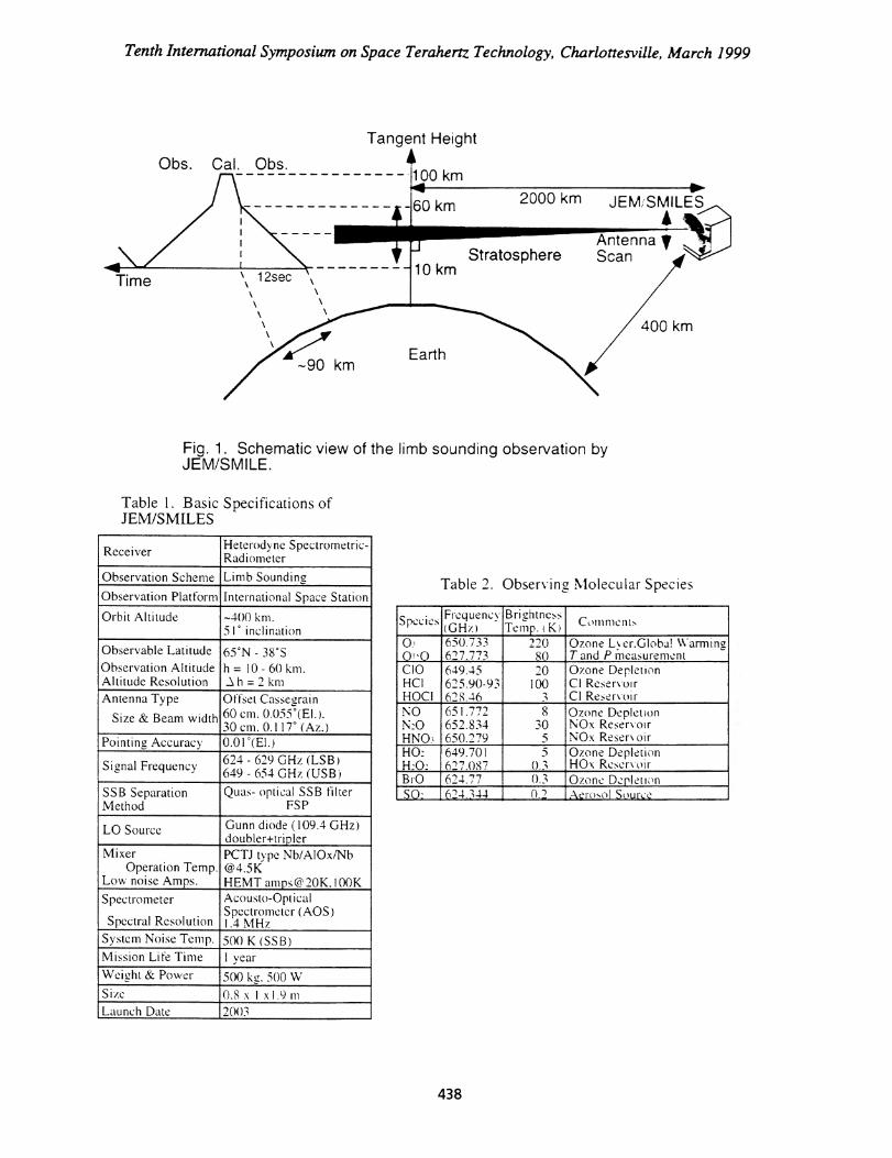
Barrath et al.. 1993). Figure 1 shows the schematic drawing of the limb sounding observation by
SMILES. We expect to start a operation of SMILES in 2003 for at least one year, and now we are
in the final design trade-off of the system. This paper mainly describes the current instrumental
desi gn of the 640 GHz SIS receiver system, and also reports some experimental results.
OVERVIEW OF JEM/SMILES
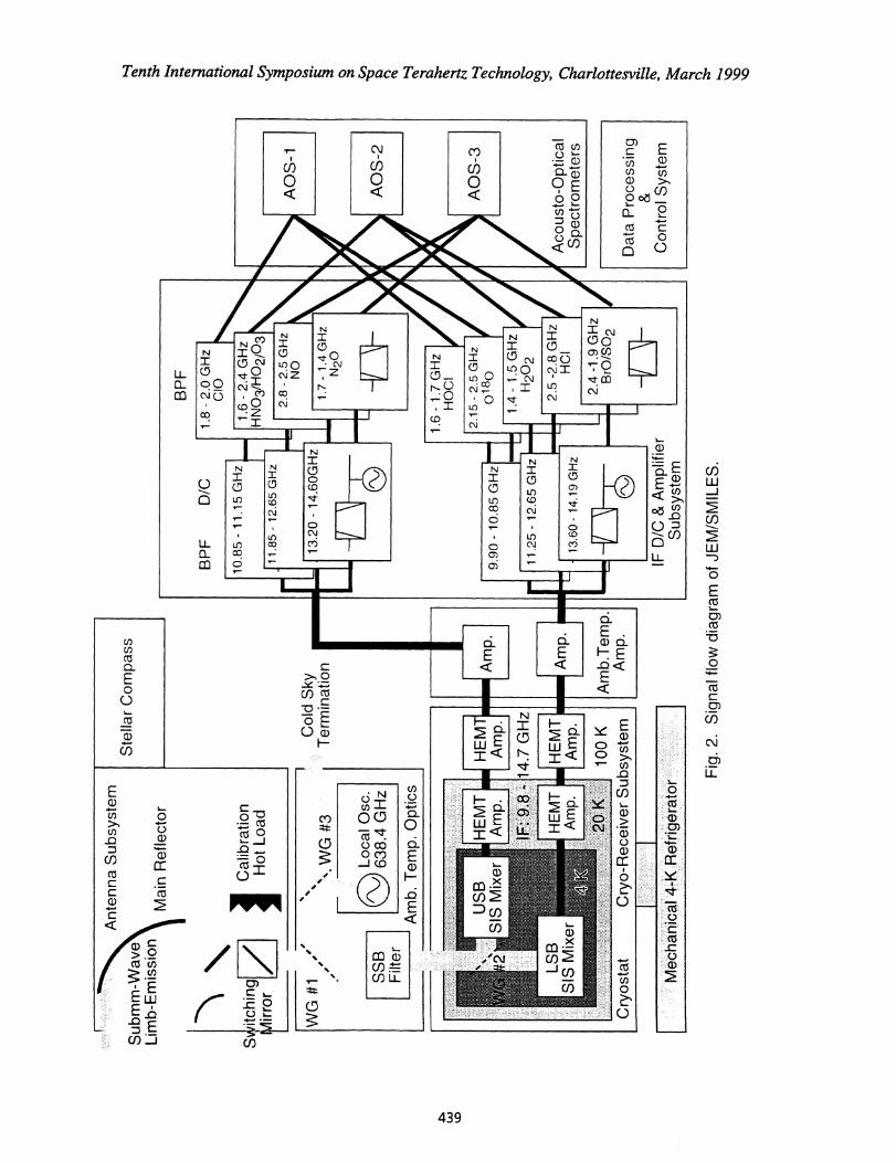
Table 1 summarizes the basic specifications of JEM/SMILES, and Fi gure 2 shows the signal
flow diagram of SMILES. We employ a hi ghly sensitive heterodyne superconductor-insulator-
superconductor (SIS) receiver, and observe twelve emission lines of stratospheric molecules as
listed in Table 2. The SIS receiver makes it possible to detect extremely weak emissions and
reduce the observational time for each observational positions. We retrieve the altitude profile of
the molecules at a high altitude resolution over a wide altitude range together with their global
diurnal and seasonal variations from the sensitive data set.
A 60 cm x 30 cm main reflector gathers the thermal radiation from the atmospheric limb
region at an altitude resolution of 2 km. The 638.4 GHz fixed frequency LO signal is injected into
the RF signal by wire grids. In order to measure the intensity of the si gnal in one sideband
precisely. we use the receiver in single-sideband mode (SSB) by a quasi-optical SSB filter. We
operate two SIS mixers simultaneously. one for upper sideband (USB) and the other for lower
sideband (LSB) detection. The IF signals of 9.8 -14.8 GHz are further down-converted in
frequency and amplified to a power level large enough for spectroscopy. In the IF subsystem only
frequency ran ges around the molecular emission lines of interest are chosen to save the band
width of the spectrometer. We use three acousto-optical spectrometers (AOSs) for high resolution
spectroscopy. The system noise temperature is expected to be less than 500 K in SSB mode,
which g ives a sensitivity of 1.3 K for an integration time of 0.2 sec and a spectral resolution of
1.4 MHz.
SUBMILLIMETER ANTENNA
We require several technical specifications in the antenna of SMILES for demonstrating a
highly sensitive limb emission technique from the space. First requirement is an altitude resolution
of 2 km with precise pointing accuracy of 0.01 We use an offset Casegrain type elliptical (60 cm
x 30 cm ) antenna. The long axis of 60 cm is chosen to realize an altitude resolution of 2 km, and
another axis is reduced to 30 cm for compactness. The main reflector of the antenna will be
polished aluminum. and special attention is paid in the frame structure of the main reflector and
thermal insulation around the antenna for minimizin g the thermal distortion. We drive the pointing
elevation an g le of the antenna in a step size smaller than 0.01'. The altitude pointing of the antenna
437
100 km
60 km
10 km
2000 km JEM, SMILES
AntennaStratosphere Scan
Tangent Height
• 400 km
A;#r-90 km
Earth
Table 2. Observin g. Molecular Species.Species Frequency
(GHz)Brightne ssTemp. (K) Comments
,() 650.733 220
.Ozone Ler.Globa! Warming
0 ! '0 6 2 7.773 80 T and P measurement,CIO 649.45 20 Ozone DepletionHCI 100 Cl ReservoirHOC1 3 Cl ReservoirNO 651.772 8 Ozone DepletionN:0 652.834 30 NOx ReservoirHNO3 650.279 5 NOx Reser\ oirHO: 649.701 5 Ozone DepletionH20.: 627.087 0.3 HOx ReservoirBrO 624.77 0.3 Ozone De.pletionSO: 624.344
,O.") _Aerosol Source
Tenth International Symposium on Space Terahertz Technology, Charlottesville, March 1999
Fig. 1. Schematic view of the limb sounding observation byJEWSMILE.
Table 1. Basic Specifications ofJEM/SMILES
Receiver
,Heterodyne Spectrometric-Radiometer
Observation Scheme Limb Sounding
Observation Platform International Space Station
Orbit Altitude —400 km.5 r inclination
Observable LatitudeObservation AltitudeAltitude Resolution
65°N - 38°Sh = 10 - 60 km._. h = 2 km
Antenna Type
Size & Beam width
Offset Cassegrain60 cm. 0.055°(EI.).30 cm, 0.117° (Az.)
Pointing Accuracy 0.01°(EI.)
Signal Frequency 624 - 629 GHz (LSB)649 - 654 GH7 (USB)
SSB SeparationMethod
Quas- optical SSB filterFSP
LO Source Gunn diode (109.4 GHz)doubler+tripler
MixerOperation Temp.
Low noise Amps.
PCTJ type Nb/A10x/[email protected] [email protected]
Spectrometer
Spectral Resolution
Acousto-OpticalSpectrometer (AOS)1.4 MHz
System Noise Temp. 500 K (SS B)Mission Life Time 1 yearWeight & Power 500 kg. 500 WSize 0.8 x 1 x1.9 mLaunch Date _2003
438
Ant
enna
Sub
syst
em
Mai
n R
efle
ctor
Stel
lar C
ompa
ss
BPF
1 Cal
ibra
tion
Hot
Loa
d
1.7
- 1.4
GH
zN
20
1.6
- 1.7
GH
zH
OC
I
9.9
0 -
10.8
5 G
Hz
2.15
- 2
.5 G
Hz
0180
1.4
- 1.
5 G
Hz
H20
2
2.5
-2.8
GH
zH
CI
2.4
-1.9
GH
zB
rO/S
02
Dat
a Pr
oces
sing
Con
trol S
yste
m
Acou
sto-
Opt
ical
Spec
trom
eter
s
Fig.
2. S
igna
l flo
w d
iagr
am o
f JE
M/S
MIL
ES
.
1.8
- 2.0
GH
zC
IO
1.6
- 2.4
GH
zH
NO
3/H
0210
3
Subm
m-W
ave
Lim
b-Em
issi
on
Svyi
tchi
ngM
irror
2.8
- 2.5
GH
zNO
BPF
D/C
10.8
5- 1
1.15
GH
z
11.8
5 - 1
2.65
GH
z
13.2
0 - 1
4.60
GH
zA
OS
-1
AO
S-2
AO
S-3
1111
11M
1111
01111
11.2
5 -
12.6
5 G
Hz
13.6
0 -
14.1
9 G
Hz
IF D
/C &
Am
plifi
erSu
bsys
tem
HEM
TAm
p.H
EMT
Amp.
WG
#1 SS
BFi
lter
HEM Am
p.14
.7 G
Hz
Amp.
Amp.
Amb.
Tem
p.Am
p.C
ryos
tat
Cry
o-R
ecei
ver S
ubsy
stem
. WG
#3
Loca
l Osc
.63
8.4
GH
z
Am
b. T
emp.
Opt
ics
Col
d Sk
yTe
rmin
atio
n
100
K
•
Tenth International Symposium on Space Terahenz Technology, Charlottesville, March 1999
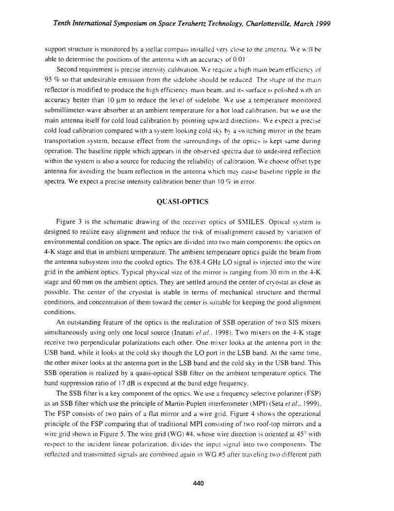
support structure is monitored by a stellar compass installed ver close to the antenna. We ‘k ill be
able to determine the positions of the antenna v. ith an accurac‘.. of 0.01' .
Second requirement is precise intensity calibration. We require a hi gh main beam efficiency of
95 % so that undesirable emission from the sidelobe should be reduced. The shape of the main
reflector is modified to produce the hi gh efficiency main beam. and its surface is polished with an
accuracy better than 10 j.irn to reduce the level of sidelobe. We use a temperature monitored
submillimeter-wave absorber at an ambient temperature for a hot load calibration. but we use the
main antenna itself for cold load calibration by pointin g upward directions. We expect a precise
cold load calibration compared with a system lookin g cold sk■ b), a switching mirror in the beamtransportation system, because effect from the surroundings of the optics is kept same duringoperation. The baseline ripple which appears in the observed spectra due to undesired reflectionwithin the system is also a source for reducing the reliability of calibration. We choose offset typeantenna for avoiding the beam reflection in the antenna which ma:, cause baseline ripple in thespectra. We expect a precise intensity calibration better than 1 0 ck in error.
QUASI-OPTICS
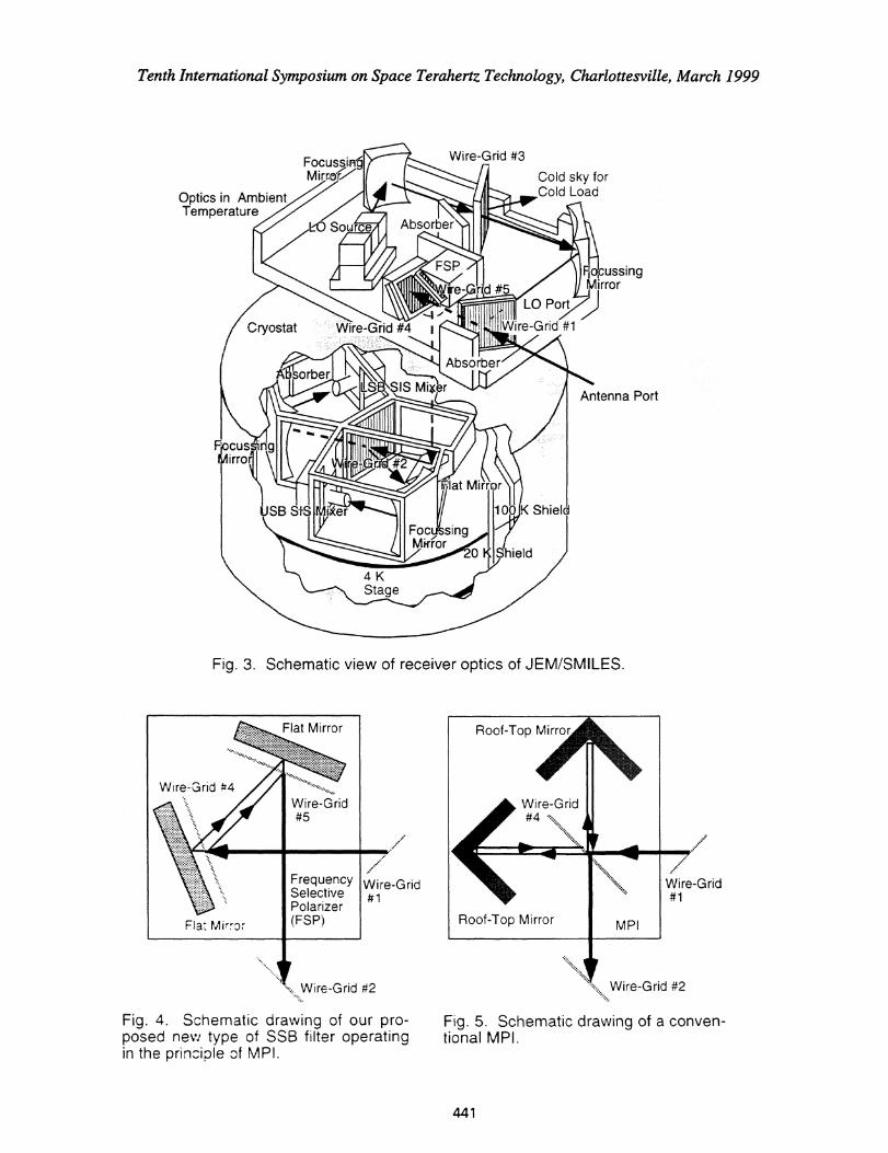
Figure 3 is the schematic drawin g of the receiver optics of SMILES. Optical system is
designed to realize easy ali gnment and reduce the risk of misali gnment caused by variation of
environmental condition on space. The optics are divided into two main components: the optics on
4-K stage and that in ambient temperature. The ambient temperature optics guide the beam from
the antenna subsystem into the cooled optics. The 638.4 GHz LO si gnal is injected into the wire
grid in the ambient optics. Typical physical size of the mirror is ran g in g from 30 mm in the 4-K
stage and 60 mm on the ambient optics. They are settled around the center of cryostat as close as
possible. The center of the cryostat is stable in terms of mechanical structure and thermal
conditions, and concentration of them toward the center is suitable for keeping the good alignment
conditions.
An outstanding feature of the optics is the realization of SSB operation of two SIS mixers
simultaneously using only one local source (Inatani el al.. 1998). Two mixers on the 4-K stage
receive two perpendicular polarizations each other. One mixer looks at the antenna port in the
USB band, while it looks at the cold sky though the LO port in the LSB band. At the same time.
the other mixer looks at the antenna port in the LSB band and the cold sky in the USB band. This
SSB operation is realized by a quasi-optical SSB filter on the ambient temperature optics. The
band suppression ratio of 17 dB is expected at the band edge frequency.
The SSB filter is a key component of the optics. We use a frequency selective polarizer (FSP)
as an SSB filter which use the principle of Martin-Puplett interferometer (MP1) (Seta et al.. 1 999).
The FSP consists of two pairs of a flat mirror and a wire grid. Fi gure 4 shows the operational
principle of the FSP comparing that of traditional MPI consistin g of two roof-top mirrors and a
wire grid shown in Figure 5. The wire grid (WG) #4, whose wire direction is oriented at 45 with
respect to the incident linear polarization. divides the input si g nial into two components. The
reflected and trinsmitted si gnals are combined a gain in WG #5 after traveling two different path
440
LSB SiS Mixer Antenna Port
K ShieldSB StS
FocussjnMirrolV
Wire-Grid #3Cold sky forCold LoadOptics in Ambient
Temperature
Cryostat Wire-Grid #4LO Port
Wire-Grid #1
Fio,cussingrror
Absorber
cus nirrorli
6at Mirror
LO Source
Absorber
4KStage
Roof-Top Mirror MPI
Wire-Grid#1
Flat Mirror
Wire-Grid #4Wire-Grid#5
Flat Mirr-or
FrequencySelectivePolarizer(FSP)
Tenth International Symposium on Space Terahertz Technology, Charlottesville, March 1999
Fig. 3. Schematic view of receiver optics of JEM/SMILES.
#2 Wire-Grid #2
Fig. 4. Schematic drawing of our pro-posed nevi type of SSB filter operatingin the principle of MP!.
Wire-Grid#1
Fig. 5. Schematic drawing of a conven-tional MPI.
441
Tenth International Symposium on Space Temhertz Technology, Charlottesville, March 1999
len gths. We can tune the transmission characteristics in frequenc\ from a imeark polar:zed input
signal to a linearly polarized si gnal in the output port by adjustin g- the tra\ eling path length
difference. The path len g ths is adjusted by a gap between the flat mirror and the w ire g rid. \\ hile
in the conventional MPI the path difference is controlled by the rela:i\ e distance difference
between the WG #4 and each roof top mirror.
The FSP is superior to the traditional MPI in two reasons for our purpose. Since ‘k e use the
SSB filter for a fixed frequency, we do not need tunin g mechanism. A mechanical tuner may be
harmful by increasing possibilities of mechanical troubles in space. So we v, ill use a fixed tuned
SSB filter without movin g mechanical structure. We adjust the position of the mirror in the
ground which works as a tuner, and fix the position ti g htly once it k tuned. The required
alignment accuracy of the mirror is estimated to be 2 um. In the traditional NIPI e must achieve
this accuracy for a traveling path length of 50 mm. and this is too difficult to achie\ e without
mechanical tuning structure. On the other hand in case of FSP. we can adjust the mirror position
in a accuracy of 2 p.m for a path length of 2 mm. which is achieved with careful machine work.
The second advantage of the FSP is elimination of standing waves generated on the MPI. In the
conventional MPI, the input signal partially returns to the input port due to undesirable
transmission and reflection of the wire grid. The returned si gnal becomes a source of standing
wave. This level is estimated to be 20 dB assumin g the undesired reflection and transmission of
the wire grid is 1%, and it is harmful to our sensitive spectroscopic obser\ ation. Althou gh in the
FSP we cannot avoid the undesirable reflection and transmission of the wire grid. this component
never comes back to the input port.
The LO signal at 638.4 GHz is generated in a phase-locked Gunn diode oscillator followed by
a doubler and a tripler, and injected into the FSP through the WG #3. The direction of wires in
WG #3 is tilted 10' from the linear polarization plane of the LO source. so that the local power is
injected into the FSP by 3 % , while each mixer, in its image band. looks at the cold sky by 97 %.
The injected LO power is equally supplied into two mixers. The LO output power. which is
expected to be around 200 pW, is sufficient for operation of two 640-GHz SIS mixers.
SUBMILLIMETER SIS MIXERS AND LOW NOISE AMPLIFIERS
The SIS is the ultimate device for sensitive millimeter and submillimeter observations
especially for 100 - 1000 GHz. Up to now only a Schottky barrier diode type mixer is used in the
space (e.g., Barath et al. 1993). SMILES employs the SIS mixer for the first time in the space.
We use simple and stable SIS mixers for increasing reliability of the mission.
We use a parallel-connected-twin-junctions (PCTJ) type SIS mixer composed of 1.25-micron
Scale Nb/A10x/Nb junctions. which are developed at the Nobeyama Radio Observatory (Noguchi
et, al., 1995; Shi et al., 1997; 1998). The mixer with this device achieves a broad-band
performance without a mechanical tuning structure. We place the SIS device in a wave guide type
mixer-mount in a typical size of 20 mm. A corrugated type feed horn is attached to the mount. and
superconducting ma gnets are inte g rated in the mount to suppress the Josephson current. One
model of the mixer covers both USB (649-654 GHz) and LSB (624-629 GHz). which is
442

Tenth International Symposium on Space Terahertz Technology, Charlottesville, March 1999
advantageous in performing space qualification tests such as vibration and radiation. The mixer
block is attached to the rigid 4K-optics directly with screws. An independent battery will be used
for a DC bias of the mixer for stable operation. Our experiment already demonstrated the mixer
noise of Tmix = 60-140 K in DSB in the frequency range of 600-650 GHz (Irimajiri et at.,
1998).
We require broad band and low power consumption low noise amplifiers for IF amplifiers.
SMILES requires a bandwidth of 5 GHz in the 640 GHz band to detect important molecules listed
in Table 2. and the IF amplifiers should be low noise over the frequency band for high sensitivity.
The power consumption of IF amplifiers should be low for using compact refrigerator. We are
developin g a hi gh-electron-mobility transistor (HEMT) amplifier with a bandwidth of 5 GHz. We
expect a noise temperature below 25 K and a gain of 20 dB with a power dissipation of 20 rnW at
the operational temperature of 20 K. We succeed in demonstratin g this performance in the
engineering model of the HEMT amplifiers.
CRYOSTAT AND MECHANICAL REFRIGERATOR
The SIS mixer needs to be operated below 4.5 K. We chose mechanical refrigerator as a
cooling system. The mechanical refrigerator is superior to liquid helium type cooler for space use
mainly for two reasons. even though it needs la ger electric power. First it can be made smaller and
lighter. because we do not need large helium tank. Second there is possibilities to expand the life
ti me keepin g its smallness and lightness.
We have been developing a compact and low power consumption type refrigerator for space
use. Inatani et al. (1997) reported the experimental results of thermal prototype of the refrigerator,
and concluded that an SIS receiver cooled by a compact 4-K mechanical refrigerator is feasible for
space use. Based on this successful experiment we are developing an advanced type of a compact
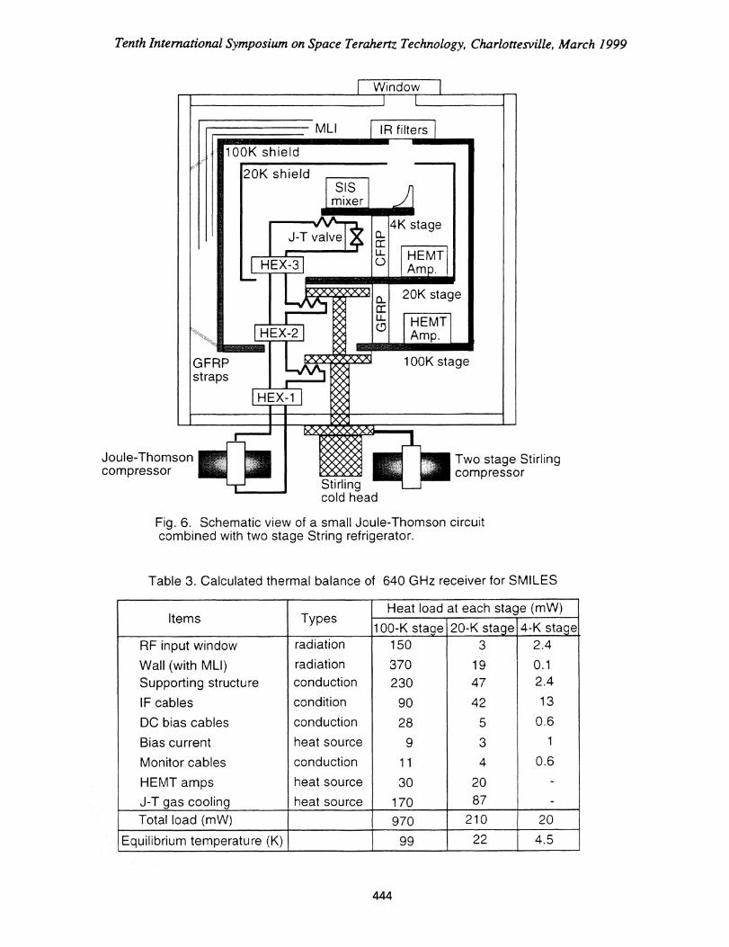
refri gerator sy stem for JEM/SMILES. which satisfies the launchin g condition of SMILES. Figure
6 show s the schematic view of our cryostat. In the cryostat. we place two SIS mixers, two HEMT
amplifier.. other two HEMT amplifiers on the 4-K. 20-K. and 100-K sta ges, respectively. The
cryostat is equipped with a Joule-Thomson circuit and a two-stage Stirling refri gerator (Kyoya et
al.. l994. Table 3 shows the thermal anal y sis of the cryostat. The 4-K stage is surrounded with
radiation Nhieids at 20 K and 100 K. and the effect of thermal radiation is minimized with a set of
carefully installed multi-layer insulators. For reducin g the thermal radiation through an RF signal
window . we place two IR filers made of porous polytetrafluoroethylene (PTFE) between the 100-
K sta ge and the outer shell. The coolin g capacity is desi gned to be 20 mW at the 4-K stage, 200
mW at the 20-K sta ge. and 1000 mW at the 100-K sta ge with an electric power consumption less
than 250 W at the AC pow er supply to the refri gerator system.
Mechanically the three sta ges are supported by a number of g lass-fiber reinforced plastics
-(GFRP) straps from the outer shell of the crvostat. The 4-K and 20-K stages are connected by
pole, -.7adeor carbon-I:her-reinforced plastic (CFR!) ) and 20-K and 100-K stage is connected by
poles of GFRP. The GFRP nd CFRP keep the thermal conductance as small as possible while
isur\ the \IN-,1:in, en\ ir)-Inent durin g the la:mch. M\ Lir film is used for outer shell window
443
20K stage
HEMTAmp.
100K stageGFRPstraps
ML1 IR filters
100K shield
20K shield
J-T valve4K stage
Joule-Thomsoncompressor
Two stage Stirlingcompressor
Stirlingcold head
Window
SISmixer
Tenth International Symposium on Space Terahertz Technology, Charlottesville, March 1999
Fig. 6. Schematic view of a small Joule-Thomson circuitcombined with two stage String refrigerator.
Table 3. Calculated thermal balance of 640 GHz receiver for SMILES
Items TypesHeat load at each stage (mW)
100-K stage 20-K stage , 4-K stage,RF input window radiation 150 3 2.4Wall (with MLI) radiation 370 19 0.1Supporting structure conduction 230 47 2.4IF cables condition 90 42 13DC bias cables conduction 28 5 0.6Bias current heat source 9 3 1Monitor cables conduction 11 4 0.6HEMT amps heat source 30 20 -J-T gas cooling heat source 170 87 -Total load (mW) 970 210 20
Equilibrium temperature (K) 99 22 4.5
444
Tenth International Symposium on Space Terahertz Technology, Charlottesville, March 1999
to keep the vacuum of cryostat during testing of the receiver on the ground.
By using the engineering model of our cryostat we succeeded in demonstrating the cooling
capability and also demonstrated that the vibration expected during the launch did not change the
capability. The detail of the refrigerator will be given elsewhere (Narasaki et al., in preparation).
IF SUBSYSTEM AND SPECTROMETER
In retrieving altitude profiles from the spectral data, frequency resolution restricts the altitude
resolution in the profile. and the frequency bandwidth restricts the lower altitude limit of the
profile. We employ AOS for getting high spectral resolution and wide bandwidth. AOS is
superior in terms of weight, size, and power consumption compared with other frequently used
digital or filter-bank type of spectrometers. We use three AOSs and achieve a total bandwidth of
about 4 GHz with a frequency resolution of 1.4 MHz. We convert a readout data of the CCD in
the AOS into a 16 bit di gital data every 10 msec. and we integrate it for 200 msec.
In order to save the bandwidth of the spectrometer. only limited frequency ranges of
molecular lines of interest are chosen from the broad band width of 5 GHz, and band-pass-filtered
into sub bands. The divided band is again combined into three AOS input ports for spectroscopy.
We realize observational bandwidth of 800 MHz for 03 using this technique.
CONCLUDING REMARKS
In this paper we reported the basic design of the 640 GHz submillimeter receiver system of
the JEM/SMILES mission. and also reported some experimental results of the engineering model.
SMILES emplo■s a sensitive 640 GHz SIS receiver. We operate two SIS mixers simultaneouslyin the SSB mode. We use a frequency selective polarizer (FSP) as an SSB filter. The STS mixerwill be cooled 4 K b■. a compact Joule-Thomson circuit combined with two stage Stringrefrigerator. In the engineering model of the refrigerator. we demonstrated the cooling capabilityof 20 mW at the 4-K stage. 200 mW at the 20-K stage and 1000 mW at the 100-K Stage. We usethree AOSs for spectrometer. and achieve a frequency resolution of 1.4 MHz and total bandwidthof 4 GHz. We expect a system noise temperature of 500 K in the SSB mode.
We are now making a final design trade-off for JEWSMILES. and the specifications
described here may be subject to minor chan ges. In 2003. SMILES will be transported to BS by
a Japanese transporter vehicle HTV launched by the H-IIA rocket. The SMILES will observe
twelYe stratospheric molecules and reveal interesting phenomena relating to the ozone chemistry.
This mission ‘k ill also demonstrate the feasibilit y- and effectiveness of the SIS receiver as a
sensi:ive s stem for monitorin g_ trace gases in the stratosphere. The success of this new technique
will open new possibilities of submillimeter wave observation in earth science and in astronomy.
ACKNOWLEDGEMENT
We-,tcknow Nlitsu _sn; Electric Comoration for sY stem design of JEM/SMILES. Sumitomo
445
Tenth International Symposium on Space Terahertz Technology, Charlottesville, March 1999
Heavy Industries, Ltd. for development of the refri gerator. Nihon Tsushinki Co. Lzd. for
development of HEMT amplifiers. Paris-Meudon Obser‘ ator■ for desi g n of AOS. Thomas
Keating Ltd. for design of optics. Radiometer Ph y sics GmbH for desi gn of LO stem. and space
instrumentation group of Technical Universit y of Denmark for design of stellar c:ompass. Indeveloping SIS junctions we are collaboratin g with Nobevama Radio ObserN ator INR0‘. We
thank Dr. S.-C. Shi and Dr. T. No p.r.uchi of NRO for technical support and discussions.
REFERENCES
F. T. Barath et al.. The Upper Atmosphere Research Satellite Microwave Limb Sounder
Instrument, J. Geophys. Res., 98, D6. 10751, 1993.
J. Inatani et al., A Submillemeter SIS Receiver Cooled by a Compact Stirrin g-JT Refrigerator.
Eighth Int. Symp. on Space Terahertz Tech.. Harvard Univ.. March. 1997.
J. Inatani, S.C. Shi, Y. Sekimoto, H. Masuko. and S. Ochiai. Single Sideband Nlixing
Submillimeter Wavelengths, Ninth Int. Symp. on Space Terahertz Tech.. Pasadena CA.
March, 1998.
Y. Irimajiri, T. Manabe, H. Masuk.o. S. Ochiai. NI. Seta. Y. Kasai. T. Noauchi. and S.C. Shi.
Wave guide Heterodyne SIS Receiver for Balloon-borne Superconductin g Submillimeter-
Wave Limb Emission Sounder at 640-GHz-band.. 23rd. Int. Conf. on IR and MM Wave.
Essex, September, 1998.
M. Kyoya, K. Narasaki. K. Ito. K. Nomi. Ni. Murakami, H. Okuda. H. Murakami. T.
Matsumoto, and Y. Matsubara. Development of Two Stage Small Stirlin g Cycle Cooler for
Temperature below 20 K. Cryogenics. 34. No5. 431. 1994.
T. Manabe et al., Space-Station Borne Submillimeter-Wave Limb-Emission Sounder for
Observin g Stratospheric Minor Constituents. URSI Commission F Int. Triennial Open Symp.
Wave Propagation and Remote Sensin g . September. Aveiro, 1998.
H. Masuko, S. Ochiai. Y.irimajiri, J. Inatani. T. Noauchi. Y. Iida. N. Ikeda. and N. Tanioka. A
Superconducting Sub-millimeter Wave Limb Emission Sounder (SMILES, on the Japanese
Experiment Module (JEM) of the Space Station for Obsrving Trace Gases in the Nliddle
Atmosphere. Eighth Int. Symp. on Space Teraherzt Tech., Harvard. MA. March. 1997.
T. No guchi, 5.-C.. Shi, and J. Inatani, An SIS Mixer Usin g Two Junctions Connected in
Parallel, IEEE trans. Appl. Superconcl.. 5. 2228. 1995.
M. Seta, T. Manabe, H. Masuk.o, J. Inatani. H. Harada. T. Noguchi. S.-C. Shi. K. Narasaki.
and Y. Abe., Submillmemeter -Wave SIS Receiver System for JEM/SMILES. Advances in
Space Research, in press. 1999.
S.C. Shi. T. Noguchi, and J. Inatani, Analysis of the Bandwidth Performances of SIS Mixers
with Distributed Junctions Arrays. Ei ghth Int. Symp. on Space Terahertz Tech.. Harvard
Univ., March. 1997.
S.C. Shi, T. Noguchi. J. Inatani. Y. Irimajiri. and T. Saito. Experimental Results of SIS Mixers
With Distributed Junction Arrays. Ninth Int. Symp. on Space Teraherzt Tech.. Pasadena. CA.
March. 1998.
446