Embed Size (px)
Citation preview
1
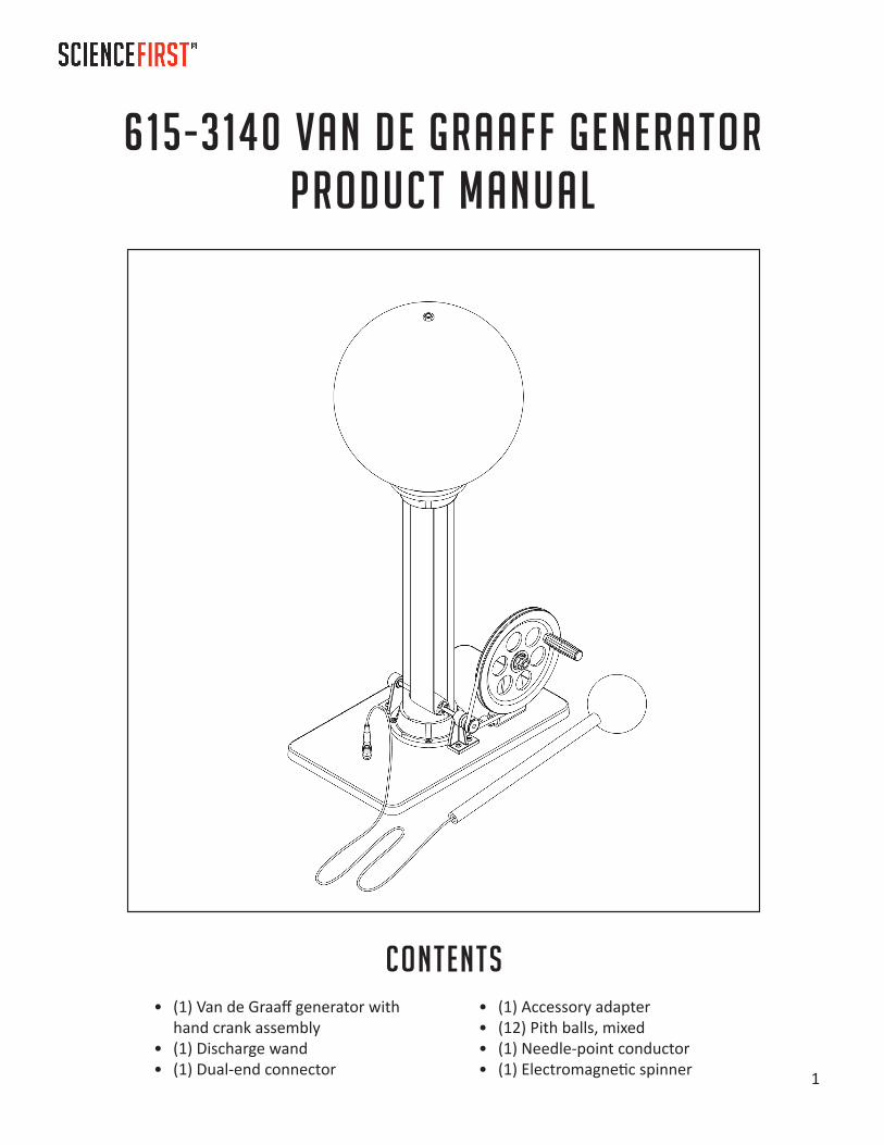
615-3140 Van de Graaff GeneratorProduct Manual
Contents• (1) Van de Graaff generator with
hand crank assembly• (1) Discharge wand• (1) Dual-end connector
• (1) Accessory adapter• (12) Pith balls, mixed• (1) Needle-point conductor• (1) Electromagnetic spinner

2
Safety
Warning:People with cardiac pacemakers or other electronic medical implants or devices should never operate or come in contact with the generator. Discharge of static electricity could cause the device to be damaged or malfunction.
Caution:This device is designed to emit high-voltage electrical energy. Do not operate outdoors or in wet or damp locations. Do not operate this unit near any electrical devices, including, but not limited to, cell phones, stereos, tablets, and computers. Science First is not responsible for damage due to improper use.
F ind demonstration guides, accessories, and more for this product at
ScienceFirst.com/docs
Adult supervision required. This generator is safe when used properly.

3
Replacement PartsOrder these and other products at ScienceFirst.com
615-3180 Replacement belt
615-3141 Belt drive for hand-crank (O-ring)
615-3161 Double-pointed spinner
615-3163 Needle-point conductor
615-3164 Accessory adapter
615-3056 Mixed pith balls
Additional Accessory Packages615-3148 Neon Wand Accessory Package
The Neon Wand accessory package adds three more exciting demonstrations to the standard Van de Graaff. The package includes the Electric Field Apparatus, Ball and Snake demo, and a Neon Wand. With these accessories, you can demonstrate polarization and magnetic fields, electrostatic repulsion and charge retention, and excitation/relaxation of light-emitting particles. Accessories also available for individual purchase, see ScienceFirst.com for more information.
615-3149 Lightning Leaper Accessory Package
The Lightning Leaper accessory package includes three accessories: Volta’s Hailstorm, Lightning Leaper, and an electroscope assembly kit. These accessories demonstrate the principles of electrostatic repulsion/attraction, electrostatic discharge, and electricity’s path of least resistance. Accessories also available for individual purchase, see ScienceFirst.com for more information.
4
Operation Notes• Running the generator: Turn the hand crank in order to generate electricity. Continue to turn
the handle as long as you desire to perform the demonstrations. When finished, stop turning the hand-crank and discharge the generator using the discharge wand.
• Discharge Wand: The discharge wand works best when plugged into the ground port at the base of the generator, but should be used even if the ground port is in use by another accessory.
• Electric shock: Although the shock caused by touching the generator is not harmful, it may feel uncomfortable and should be avoided.
• Humidity: Best results are obtained in low humidity. We recommend operating at humidity levels of 75% or less. High humidity drastically shortens belt life.
How to Discharge the GeneratorAlways discharge the generator after operation. 1. Hold the discharge wand by the handle and bring it near the dome of the Van de Graaff. You should
hear and/or see a spark. You may need to do this a few times, depending on how much charge has built on the dome.
2. The dome is now safe to touch.
Accessory Plug• The hand-crank Van de Graaff generator has two accessory ports: one in the bolt on top of the
dome, and the other on a suction-cup adapter that attaches anywhere on the dome. The dual-ended wire and the needle-point adapter can both be plugged into either port as needed.
• If your accessory adapter does not maintain suction on the dome, try wetting the bottom with a small amount of water before attaching it to the dome.
Visit us online at ScienceFirst.com/docs to find demonstration guides for the Van de Graaff generator
and its accessories.
5
TroubleshootingIf your Van de Graaff generator does not work, has weak lightning discharges, or low voltage yield, follow the steps below:
1. Check all moving parts to ensure they are functional. Ensure the belt is not twisted and the o-ring is in place around both outer pulleys (see assembly step 7.)
2. Check humidity. The generator won’t work well on high-humidity days. If the humidity is high, use a hair dryer to dry the inside of the generator and dome immediately before operation.
3. Stretch the belt. If the belt is too tight, the generator won’t work. Remove the belt and stretch it an additional 6–8 inches several times (see “Replacing the Belt” on page 8 for instructions). Take care not to overstretch the belt.
4. Remove lint from the belt, column, and dome with alcohol and a lint-free cloth, then allow to dry (see “Maintenance” for instructions).
MaintenanceClean the belt after every 50 operating hours using the following procedure:
1. Remove the dome and upper comb assembly.
2. Wet a lint-free cloth with alcohol.
3. Hold the cloth against the belt on the upper pulley.
4. Slowly turn the hand-crank.Note: Static electricity will continue to generate even without the dome. As such, you may feel a shock when performing this maintenance. While the shock is not harmful, if you wish to avoid it, you can remove the belt before wiping it down. See “Replacing the Belt” starting on page 8 for instructions.
5. Replace the upper comb assembly and dome.Note: If you wish to fully wipe down the inside of the belt and the pulleys, see “Replacing the Belt” starting on page 8 and wipe down the belt and pulleys rather than replacing the belt.
StorageTo store the Van de Graaff generator for an extended period of time, remove the belt to relax its tension so it maintains its strength. See “Removing/Replacing the Belt” for instructions.
6
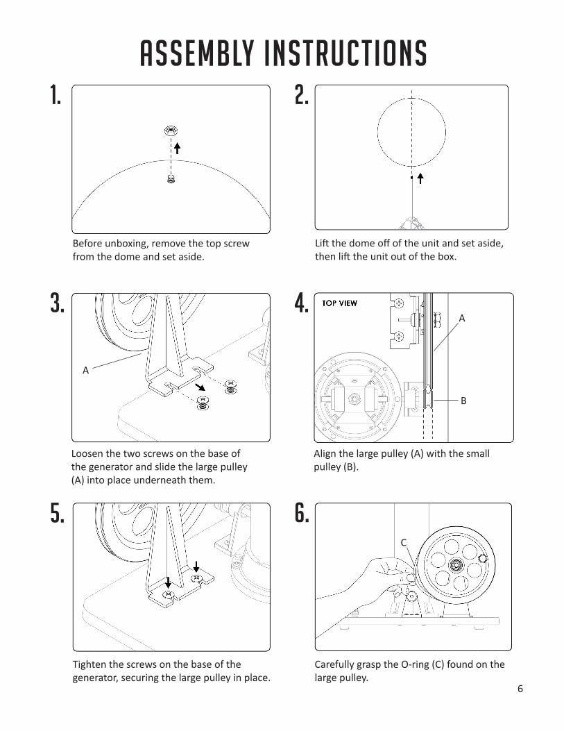
Before unboxing, remove the top screw from the dome and set aside.
Lift the dome off of the unit and set aside, then lift the unit out of the box.
Loosen the two screws on the base of the generator and slide the large pulley (A) into place underneath them.
Align the large pulley (A) with the small pulley (B).
Carefully grasp the O-ring (C) found on the large pulley.
Tighten the screws on the base of the generator, securing the large pulley in place.
1. 2.
3. 4.
5. 6.
Assembly Instructions
A
A
B
C
7
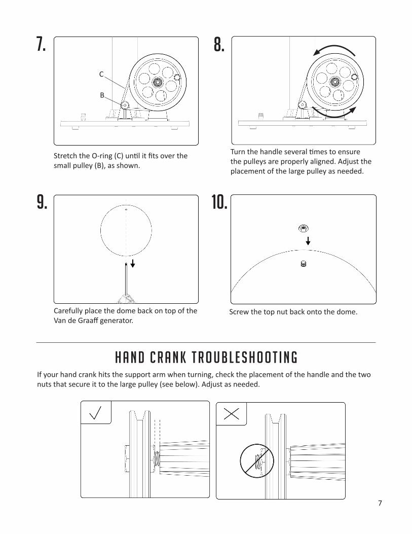
If your hand crank hits the support arm when turning, check the placement of the handle and the two nuts that secure it to the large pulley (see below). Adjust as needed.
H a n d C r a n k T r o u b l e s h o o t i n g
7. 8.
9. 10.
Stretch the O-ring (C) until it fits over the small pulley (B), as shown.
Turn the handle several times to ensure the pulleys are properly aligned. Adjust the placement of the large pulley as needed.
Carefully place the dome back on top of the Van de Graaff generator.
Screw the top nut back onto the dome.
C
B
8
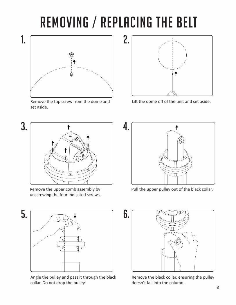
Remove the top screw from the dome and set aside.
Lift the dome off of the unit and set aside.
Remove the upper comb assembly by unscrewing the four indicated screws.
Pull the upper pulley out of the black collar.
Remove the black collar, ensuring the pulley doesn’t fall into the column.
Angle the pulley and pass it through the black collar. Do not drop the pulley.
1. 2.
3. 4.
5. 6.
Removing / Replacing the Belt
9
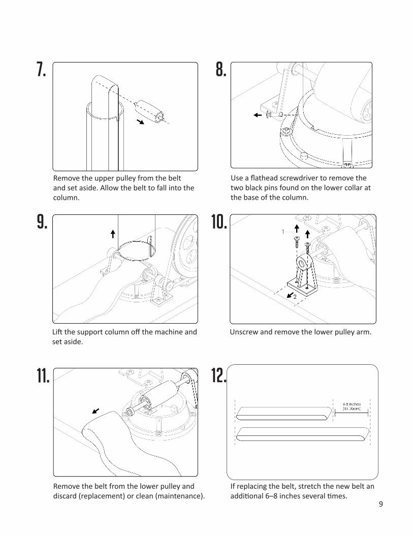
Remove the upper pulley from the belt and set aside. Allow the belt to fall into the column.
Use a flathead screwdriver to remove the two black pins found on the lower collar at the base of the column.
Lift the support column off the machine and set aside.
Unscrew and remove the lower pulley arm.
If replacing the belt, stretch the new belt an additional 6–8 inches several times.
Remove the belt from the lower pulley and discard (replacement) or clean (maintenance).
7. 8.
9. 10.
11. 12.
10
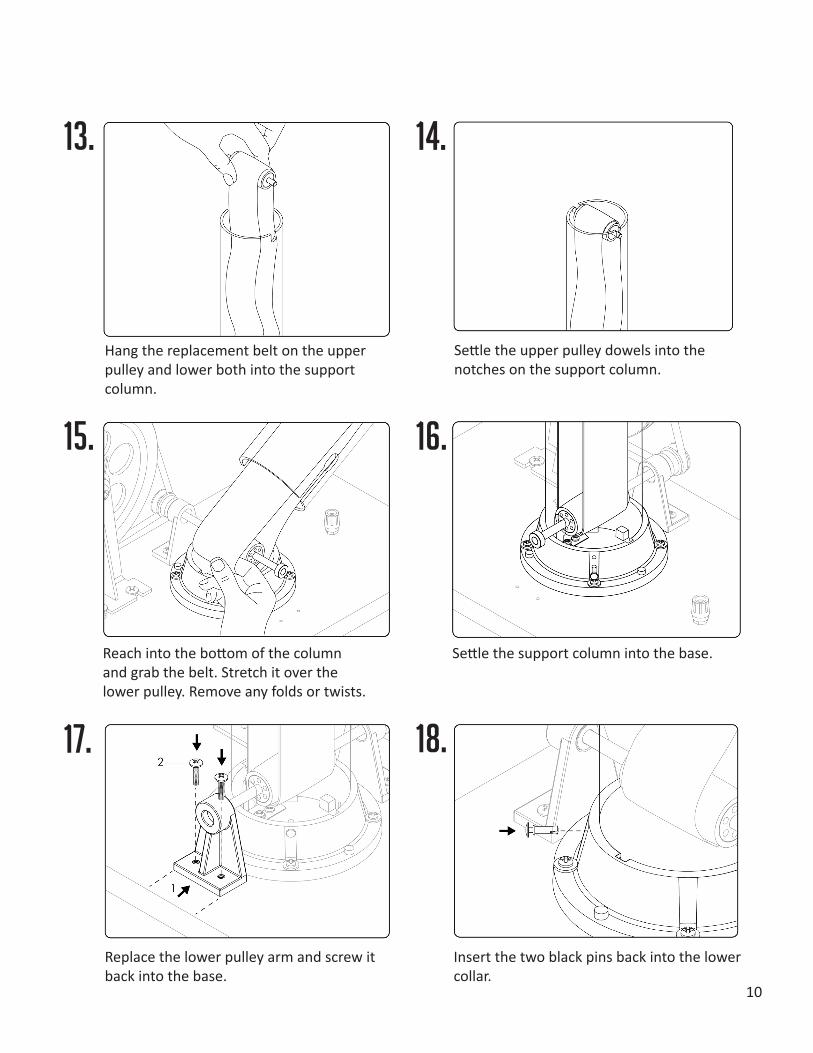
Hang the replacement belt on the upper pulley and lower both into the support column.
Settle the upper pulley dowels into the notches on the support column.
Reach into the bottom of the column and grab the belt. Stretch it over the lower pulley. Remove any folds or twists.
Settle the support column into the base.
Insert the two black pins back into the lower collar.
Replace the lower pulley arm and screw it back into the base.
13. 14.
15. 16.
17. 18.
11
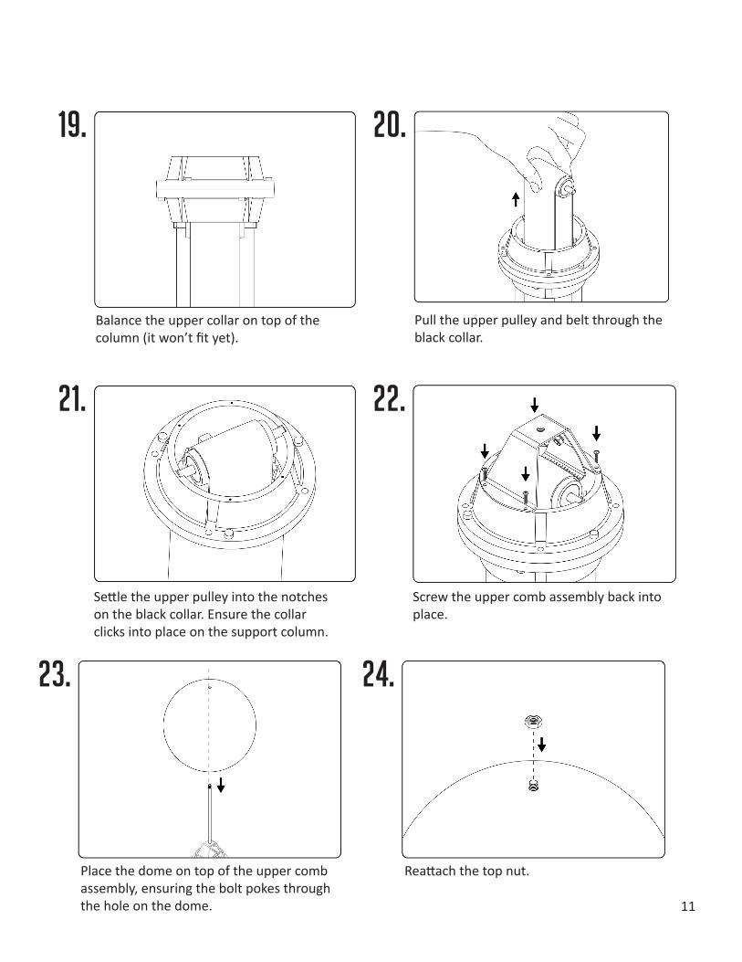
Balance the upper collar on top of the column (it won’t fit yet).
Pull the upper pulley and belt through the black collar.
Settle the upper pulley into the notches on the black collar. Ensure the collar clicks into place on the support column.
Screw the upper comb assembly back into place.
Place the dome on top of the upper comb assembly, ensuring the bolt pokes through the hole on the dome.
Reattach the top nut.
19. 20.
21. 22.
23. 24.