Embed Size (px)
Citation preview

6100A/6180A
User Guide
6100A/6180A Paperless graphic recorderVersions 5.4 and later
HA028910/11October 2014


© 2014 Eurotherm LimitedAll rights are strictly reserved. No part of this document may be reproduced, modifi ed, or transmitted in any form by any means, nor may it be stored in a retrieval system other than for the purpose to act as an aid in operating the equipment to which the document relates, without the prior written permission of Eurotherm Limited.
Eurotherm Limited pursues a policy of continuous development and product improvement. The specifi -cations in this document may therefore be changed without notice. The information in this document is given in good faith, but is intended for guidance only. Eurotherm Limited will accept no responsibility for any losses arising from errors in this document.
100/180 mm PAPERLESS GRAPHIC RECORDER: USER GUIDE
User GuideContents Page i
HA028910Issue 11 Oct 14
PAPERLESS GRAPHIC RECORDER
USER GUIDE
LIST OF SECTIONS
Section Page1 INTRODUCTION . . . . . . . . . . . . . . . . . . . . . . . . . . . . . . . . . . . . . . . . . . . . . . . . . . . . . . . . 22 INSTALLATION . . . . . . . . . . . . . . . . . . . . . . . . . . . . . . . . . . . . . . . . . . . . . . . . . . . . . . . . . . 23 PROCESS VARIABLE DISPLAY . . . . . . . . . . . . . . . . . . . . . . . . . . . . . . . . . . . . . . . . . . . . . 144 SETTING UP THE RECORDER . . . . . . . . . . . . . . . . . . . . . . . . . . . . . . . . . . . . . . . . . . . . . 515 FILE . . . . . . . . . . . . . . . . . . . . . . . . . . . . . . . . . . . . . . . . . . . . . . . . . . . . . . . . . . . . . . . . . . . . 2406 BRIDGE . . . . . . . . . . . . . . . . . . . . . . . . . . . . . . . . . . . . . . . . . . . . . . . . . . . . . . . . . . . . . . . . 2437 SCREEN BUILDER . . . . . . . . . . . . . . . . . . . . . . . . . . . . . . . . . . . . . . . . . . . . . . . . . . . . . . . 2528 MODBUS TCP SLAVE COMMS . . . . . . . . . . . . . . . . . . . . . . . . . . . . . . . . . . . . . . . . . . . . 2809 ANALOGUE OUTPUTS . . . . . . . . . . . . . . . . . . . . . . . . . . . . . . . . . . . . . . . . . . . . . . . . . . . 33210 EVENT INPUTS . . . . . . . . . . . . . . . . . . . . . . . . . . . . . . . . . . . . . . . . . . . . . . . . . . . . . . . . . 33411 TRANSMITTER POWER SUPPLY . . . . . . . . . . . . . . . . . . . . . . . . . . . . . . . . . . . . . . . . . . 33512 ASCII PRINTER . . . . . . . . . . . . . . . . . . . . . . . . . . . . . . . . . . . . . . . . . . . . . . . . . . . . . . . . . 33813 PORTABLE CASE OPTIONS . . . . . . . . . . . . . . . . . . . . . . . . . . . . . . . . . . . . . . . . . . . . . . 34814 REMOTE CJ BLOCK OPTION . . . . . . . . . . . . . . . . . . . . . . . . . . . . . . . . . . . . . . . . . . . . 36115 THERMAL UNIFORMITY SURVEY . . . . . . . . . . . . . . . . . . . . . . . . . . . . . . . . . . . . . . . . . 371ANNEX A: SPECIFICATION . . . . . . . . . . . . . . . . . . . . . . . . . . . . . . . . . . . . . . . . . . . . . . . . . 375ANNEX B: REFERENCE . . . . . . . . . . . . . . . . . . . . . . . . . . . . . . . . . . . . . . . . . . . . . . . . . . . . . 385ANNEX C: WEB SERVER DETAILS . . . . . . . . . . . . . . . . . . . . . . . . . . . . . . . . . . . . . . . . . . . 415INDEX . . . . . . . . . . . . . . . . . . . . . . . . . . . . . . . . . . . . . . . . . . . . . . . . . . . . . . . . . . . . . . . . . . . . 419
EFFECTIVITY
This manual refers to recorders fi tted with software version 5.4. To determine the software version fi tted to the recorder, the 'About' screen may be accessed as described in section 4.6.11.
100/180 mm PAPERLESS GRAPHIC RECORDER: USER GUIDE
HA028910Issue 11 Oct 14
User GuideContents Page ii
PAPERLESS GRAPHICS RECORDER USER GUIDE
LIST OF CONTENTS
Section PageSAFETY NOTES . . . . . . . . . . . . . . . . . . . . . . . . . . . . . . . . . . . . . . . . . . . . . . . . . . . . . . . . . . . 1
SYMBOLS USED ON THE RECORDER LABELLING . . . . . . . . . . . . . . . . . . . . . . . 11 INTRODUCTION . . . . . . . . . . . . . . . . . . . . . . . . . . . . . . . . . . . . . . . . . . . . . . . . . . . . . . . . 21.1 UNPACKING THE RECORDER . . . . . . . . . . . . . . . . . . . . . . . . . . . . . . . . . . . . . . . . . . . 22 INSTALLATION . . . . . . . . . . . . . . . . . . . . . . . . . . . . . . . . . . . . . . . . . . . . . . . . . . . . . . . . . 22.1 MECHANICAL INSTALLATION . . . . . . . . . . . . . . . . . . . . . . . . . . . . . . . . . . . . . . . . . . . 22.2 ELECTRICAL INSTALLATION . . . . . . . . . . . . . . . . . . . . . . . . . . . . . . . . . . . . . . . . . . . . 5
2.2.1 Signal wiring . . . . . . . . . . . . . . . . . . . . . . . . . . . . . . . . . . . . . . . . . . . . . . . . . . . . . . 5CONNECTOR WIRING DETAILS . . . . . . . . . . . . . . . . . . . . . . . . . . . . . . . . . . . . . . . 5
2.2.2 Supply voltage wiring . . . . . . . . . . . . . . . . . . . . . . . . . . . . . . . . . . . . . . . . . . . . . . 9LINE SUPPLY . . . . . . . . . . . . . . . . . . . . . . . . . . . . . . . . . . . . . . . . . . . . . . . . . . . . . . . . 9LOW VOLTAGE SUPPLY OPTION* . . . . . . . . . . . . . . . . . . . . . . . . . . . . . . . . . . . . . 9
2.3 ACCESS FLAP . . . . . . . . . . . . . . . . . . . . . . . . . . . . . . . . . . . . . . . . . . . . . . . . . . . . . . . . . 102.3.1 Stylus . . . . . . . . . . . . . . . . . . . . . . . . . . . . . . . . . . . . . . . . . . . . . . . . . . . . . . . . . . . . 112.3.2 Card slot . . . . . . . . . . . . . . . . . . . . . . . . . . . . . . . . . . . . . . . . . . . . . . . . . . . . . . . . . 11
LED INDICATORS . . . . . . . . . . . . . . . . . . . . . . . . . . . . . . . . . . . . . . . . . . . . . . . . . . . 112.3.3 USB Front Port . . . . . . . . . . . . . . . . . . . . . . . . . . . . . . . . . . . . . . . . . . . . . . . . . . . 11
2.4 LOCKABLE FLAP OPTION . . . . . . . . . . . . . . . . . . . . . . . . . . . . . . . . . . . . . . . . . . . . . . 122.4.1 Flap lock operation . . . . . . . . . . . . . . . . . . . . . . . . . . . . . . . . . . . . . . . . . . . . . . . . 12
ARCHIVE INACTIVE . . . . . . . . . . . . . . . . . . . . . . . . . . . . . . . . . . . . . . . . . . . . . . . . . . 12ARCHIVE ACTIVE . . . . . . . . . . . . . . . . . . . . . . . . . . . . . . . . . . . . . . . . . . . . . . . . . . . . 13
3 PROCESS VARIABLE DISPLAY . . . . . . . . . . . . . . . . . . . . . . . . . . . . . . . . . . . . . . . . . . . . 14TRUNCATION OF NUMERIC VALUES . . . . . . . . . . . . . . . . . . . . . . . . . . . . . . . . . . 14CURRENT TRACE ALARM ICONS . . . . . . . . . . . . . . . . . . . . . . . . . . . . . . . . . . . . . . 15
3.1 STATUS BAR . . . . . . . . . . . . . . . . . . . . . . . . . . . . . . . . . . . . . . . . . . . . . . . . . . . . . . . . . . . 153.1.1 Current access level . . . . . . . . . . . . . . . . . . . . . . . . . . . . . . . . . . . . . . . . . . . . . . . 153.1.2 Page name . . . . . . . . . . . . . . . . . . . . . . . . . . . . . . . . . . . . . . . . . . . . . . . . . . . . . . . 153.1.3 Alarm indication . . . . . . . . . . . . . . . . . . . . . . . . . . . . . . . . . . . . . . . . . . . . . . . . . . 16
INSTRUMENT ALARM . . . . . . . . . . . . . . . . . . . . . . . . . . . . . . . . . . . . . . . . . . . . . . . . 16CHANNEL ALARM . . . . . . . . . . . . . . . . . . . . . . . . . . . . . . . . . . . . . . . . . . . . . . . . . . . 18CHANGE BATTERY . . . . . . . . . . . . . . . . . . . . . . . . . . . . . . . . . . . . . . . . . . . . . . . . . . 18DISK ICON . . . . . . . . . . . . . . . . . . . . . . . . . . . . . . . . . . . . . . . . . . . . . . . . . . . . . . . . . . 18FTP ICON . . . . . . . . . . . . . . . . . . . . . . . . . . . . . . . . . . . . . . . . . . . . . . . . . . . . . . . . . . 18CONFIGURATION LOCKED INDICATOR . . . . . . . . . . . . . . . . . . . . . . . . . . . . . . . 18TRIAL MODE INDICATOR . . . . . . . . . . . . . . . . . . . . . . . . . . . . . . . . . . . . . . . . . . . . 18
3.1.4 Summary menu . . . . . . . . . . . . . . . . . . . . . . . . . . . . . . . . . . . . . . . . . . . . . . . . . . . 19INSTRUMENT ALARM SUMMARY . . . . . . . . . . . . . . . . . . . . . . . . . . . . . . . . . . . . . 19ACK ALL ALARMS . . . . . . . . . . . . . . . . . . . . . . . . . . . . . . . . . . . . . . . . . . . . . . . . . . . 19ALARM SUMMARY PAGE . . . . . . . . . . . . . . . . . . . . . . . . . . . . . . . . . . . . . . . . . . . . . 20ALARM ACKNOWLEDGEMENT . . . . . . . . . . . . . . . . . . . . . . . . . . . . . . . . . . . . . . . 21BATCH SUMMARY . . . . . . . . . . . . . . . . . . . . . . . . . . . . . . . . . . . . . . . . . . . . . . . . . . . 22MESSAGE LOG . . . . . . . . . . . . . . . . . . . . . . . . . . . . . . . . . . . . . . . . . . . . . . . . . . . . . 24MESSAGE TYPE FILTER . . . . . . . . . . . . . . . . . . . . . . . . . . . . . . . . . . . . . . . . . . . . . . . 25PERIOD FILTER . . . . . . . . . . . . . . . . . . . . . . . . . . . . . . . . . . . . . . . . . . . . . . . . . . . . . . 25OPTION MENU . . . . . . . . . . . . . . . . . . . . . . . . . . . . . . . . . . . . . . . . . . . . . . . . . . . . . 26REMOVE MEDIA . . . . . . . . . . . . . . . . . . . . . . . . . . . . . . . . . . . . . . . . . . . . . . . . . . . . 27
3.2 NAVIGATION KEYS . . . . . . . . . . . . . . . . . . . . . . . . . . . . . . . . . . . . . . . . . . . . . . . . . . . . 283.2.1 Key functions . . . . . . . . . . . . . . . . . . . . . . . . . . . . . . . . . . . . . . . . . . . . . . . . . . . . . 28
ROOT MENU KEYS . . . . . . . . . . . . . . . . . . . . . . . . . . . . . . . . . . . . . . . . . . . . . . . . . . 283.3 FIRST SWITCH-ON . . . . . . . . . . . . . . . . . . . . . . . . . . . . . . . . . . . . . . . . . . . . . . . . . . . . . 31
3.3.1 Access to Confi guration . . . . . . . . . . . . . . . . . . . . . . . . . . . . . . . . . . . . . . . . . . . . 32TROUBLE SHOOTING . . . . . . . . . . . . . . . . . . . . . . . . . . . . . . . . . . . . . . . . . . . . . . . 33TEXT STRING ENTRY . . . . . . . . . . . . . . . . . . . . . . . . . . . . . . . . . . . . . . . . . . . . . . . . 33
3.4 DISPLAY MODES . . . . . . . . . . . . . . . . . . . . . . . . . . . . . . . . . . . . . . . . . . . . . . . . . . . . . . 35TREND HISTORY . . . . . . . . . . . . . . . . . . . . . . . . . . . . . . . . . . . . . . . . . . . . . . . . . . . . 35TIME CHANGE RECORDS . . . . . . . . . . . . . . . . . . . . . . . . . . . . . . . . . . . . . . . . . . . . 36
3.4.1 Vertical Trend display . . . . . . . . . . . . . . . . . . . . . . . . . . . . . . . . . . . . . . . . . . . . . . 363.4.2 Horizontal Trend display . . . . . . . . . . . . . . . . . . . . . . . . . . . . . . . . . . . . . . . . . . . 38

100/180 mm PAPERLESS GRAPHIC RECORDER: USER GUIDE
User GuideContents Page iii
HA028910Issue 11 Oct 14
3.4.3 Circular Trend . . . . . . . . . . . . . . . . . . . . . . . . . . . . . . . . . . . . . . . . . . . . . . . . . . . . 40TREND MODES . . . . . . . . . . . . . . . . . . . . . . . . . . . . . . . . . . . . . . . . . . . . . . . . . . . . . 40NORMAL VIEW . . . . . . . . . . . . . . . . . . . . . . . . . . . . . . . . . . . . . . . . . . . . . . . . . . . . . 41NORMAL VIEW FEATURES . . . . . . . . . . . . . . . . . . . . . . . . . . . . . . . . . . . . . . . . . . . 42FULL SCREEN DISPLAY . . . . . . . . . . . . . . . . . . . . . . . . . . . . . . . . . . . . . . . . . . . . . . 42TIMESTAMPS . . . . . . . . . . . . . . . . . . . . . . . . . . . . . . . . . . . . . . . . . . . . . . . . . . . . . . . 43OTHER NOTES . . . . . . . . . . . . . . . . . . . . . . . . . . . . . . . . . . . . . . . . . . . . . . . . . . . . . . 43
3.4.4 Vertical bargraph . . . . . . . . . . . . . . . . . . . . . . . . . . . . . . . . . . . . . . . . . . . . . . . . . . 44FACEPLATES ABOVE THE BARS . . . . . . . . . . . . . . . . . . . . . . . . . . . . . . . . . . . . . . 44FACEPLATES AT RIGHT-HAND EDGE . . . . . . . . . . . . . . . . . . . . . . . . . . . . . . . . . . 44
3.4.5 Horizontal bargraph . . . . . . . . . . . . . . . . . . . . . . . . . . . . . . . . . . . . . . . . . . . . . . 463.4.6 Numeric . . . . . . . . . . . . . . . . . . . . . . . . . . . . . . . . . . . . . . . . . . . . . . . . . . . . . . . . . 48
3.5 OPERATOR NOTES . . . . . . . . . . . . . . . . . . . . . . . . . . . . . . . . . . . . . . . . . . . . . . . . . . . . 504 SETTING UP THE RECORDER . . . . . . . . . . . . . . . . . . . . . . . . . . . . . . . . . . . . . . . . . . . . 514.1 ARCHIVE . . . . . . . . . . . . . . . . . . . . . . . . . . . . . . . . . . . . . . . . . . . . . . . . . . . . . . . . . . . . . . 52
4.1.1 Local Archive . . . . . . . . . . . . . . . . . . . . . . . . . . . . . . . . . . . . . . . . . . . . . . . . . . . . . 52BRING ARCHIVE UP TO DATE . . . . . . . . . . . . . . . . . . . . . . . . . . . . . . . . . . . . . . . . . 53ARCHIVE ALL . . . . . . . . . . . . . . . . . . . . . . . . . . . . . . . . . . . . . . . . . . . . . . . . . . . . . . . 53ARCHIVING WITH THE LOCKABLE FLAP OPTION . . . . . . . . . . . . . . . . . . . . . . . 53
4.1.2 Remote archiving (FTP transfer) . . . . . . . . . . . . . . . . . . . . . . . . . . . . . . . . . . . . . 544.2 SAVE / RESTORE . . . . . . . . . . . . . . . . . . . . . . . . . . . . . . . . . . . . . . . . . . . . . . . . . . . . . . . 55
4.2.1 Save . . . . . . . . . . . . . . . . . . . . . . . . . . . . . . . . . . . . . . . . . . . . . . . . . . . . . . . . . . . . . 56SAVE AS . . . . . . . . . . . . . . . . . . . . . . . . . . . . . . . . . . . . . . . . . . . . . . . . . . . . . . . . . . . 56
4.2.2 Restore . . . . . . . . . . . . . . . . . . . . . . . . . . . . . . . . . . . . . . . . . . . . . . . . . . . . . . . . . . 564.2.3 New . . . . . . . . . . . . . . . . . . . . . . . . . . . . . . . . . . . . . . . . . . . . . . . . . . . . . . . . . . . . . 564.2.4 Text . . . . . . . . . . . . . . . . . . . . . . . . . . . . . . . . . . . . . . . . . . . . . . . . . . . . . . . . . . . . . 564.2.5 Import screen . . . . . . . . . . . . . . . . . . . . . . . . . . . . . . . . . . . . . . . . . . . . . . . . . . . . 564.2.6 Export screen . . . . . . . . . . . . . . . . . . . . . . . . . . . . . . . . . . . . . . . . . . . . . . . . . . . . 564.2.7 Import User Linearisation . . . . . . . . . . . . . . . . . . . . . . . . . . . . . . . . . . . . . . . . . 574.2.8 Export User Linearisation . . . . . . . . . . . . . . . . . . . . . . . . . . . . . . . . . . . . . . . . . . 574.2.9 Import printer driver . . . . . . . . . . . . . . . . . . . . . . . . . . . . . . . . . . . . . . . . . . . . . . . 57
4.3 CONFIG KEY . . . . . . . . . . . . . . . . . . . . . . . . . . . . . . . . . . . . . . . . . . . . . . . . . . . . . . . . . . 584.3.1 Instrument confi guration . . . . . . . . . . . . . . . . . . . . . . . . . . . . . . . . . . . . . . . . . . . 63
INSTRUMENT NAME . . . . . . . . . . . . . . . . . . . . . . . . . . . . . . . . . . . . . . . . . . . . . . . . . 63NORMAL/SAVER DISPLAY . . . . . . . . . . . . . . . . . . . . . . . . . . . . . . . . . . . . . . . . . . . . 63SAVE AFTER . . . . . . . . . . . . . . . . . . . . . . . . . . . . . . . . . . . . . . . . . . . . . . . . . . . . . . . . 63MODBUS ADDRESS . . . . . . . . . . . . . . . . . . . . . . . . . . . . . . . . . . . . . . . . . . . . . . . . . 63MODBUS SECURITY DISABLED . . . . . . . . . . . . . . . . . . . . . . . . . . . . . . . . . . . . . . . 63COMMS CHANNEL TIMEOUT. . . . . . . . . . . . . . . . . . . . . . . . . . . . . . . . . . . . . . . . . 63PRESET HOUR . . . . . . . . . . . . . . . . . . . . . . . . . . . . . . . . . . . . . . . . . . . . . . . . . . . . . . 64PRESET MINUTE . . . . . . . . . . . . . . . . . . . . . . . . . . . . . . . . . . . . . . . . . . . . . . . . . . . . 64DISABLE WARNING DIALOGS . . . . . . . . . . . . . . . . . . . . . . . . . . . . . . . . . . . . . . . . 64SHOW OPERATOR NOTES LIST . . . . . . . . . . . . . . . . . . . . . . . . . . . . . . . . . . . . . . . 64
4.3.2 Group confi guration . . . . . . . . . . . . . . . . . . . . . . . . . . . . . . . . . . . . . . . . . . . . . . . 65GROUP NUMBER . . . . . . . . . . . . . . . . . . . . . . . . . . . . . . . . . . . . . . . . . . . . . . . . . . . . 66TREND UNITS . . . . . . . . . . . . . . . . . . . . . . . . . . . . . . . . . . . . . . . . . . . . . . . . . . . . . . . 66DESCRIPTOR . . . . . . . . . . . . . . . . . . . . . . . . . . . . . . . . . . . . . . . . . . . . . . . . . . . . . . . 66TREND TYPE . . . . . . . . . . . . . . . . . . . . . . . . . . . . . . . . . . . . . . . . . . . . . . . . . . . . . . . . 66A/B SWITCHING . . . . . . . . . . . . . . . . . . . . . . . . . . . . . . . . . . . . . . . . . . . . . . . . . . . . 67TREND SPEED/TREND INTERVAL . . . . . . . . . . . . . . . . . . . . . . . . . . . . . . . . . . . . . 67CIRCULAR SETTINGS . . . . . . . . . . . . . . . . . . . . . . . . . . . . . . . . . . . . . . . . . . . . . . . 67CIRCULAR SPEED . . . . . . . . . . . . . . . . . . . . . . . . . . . . . . . . . . . . . . . . . . . . . . . . . . . 67CIRCULAR CHART FULL . . . . . . . . . . . . . . . . . . . . . . . . . . . . . . . . . . . . . . . . . . . . . 67START AT . . . . . . . . . . . . . . . . . . . . . . . . . . . . . . . . . . . . . . . . . . . . . . . . . . . . . . . . . . 67GRID TYPE . . . . . . . . . . . . . . . . . . . . . . . . . . . . . . . . . . . . . . . . . . . . . . . . . . . . . . . . . 68NONE . . . . . . . . . . . . . . . . . . . . . . . . . . . . . . . . . . . . . . . . . . . . . . . . . . . . . . . . . . . . . 68LINEAR . . . . . . . . . . . . . . . . . . . . . . . . . . . . . . . . . . . . . . . . . . . . . . . . . . . . . . . . . . . . 68LOG . . . . . . . . . . . . . . . . . . . . . . . . . . . . . . . . . . . . . . . . . . . . . . . . . . . . . . . . . . . . . . . 68FROM POINT . . . . . . . . . . . . . . . . . . . . . . . . . . . . . . . . . . . . . . . . . . . . . . . . . . . . . . . 68RECORDING ENABLE . . . . . . . . . . . . . . . . . . . . . . . . . . . . . . . . . . . . . . . . . . . . . . . . 68RECORDING SPEED/RECORDING INTERVAL . . . . . . . . . . . . . . . . . . . . . . . . . . . 69TREND HISTORY DURATION . . . . . . . . . . . . . . . . . . . . . . . . . . . . . . . . . . . . . . . . . 69ARCHIVE TO MEDIA ENABLE/ARCHIVE VIA FTP ENABLE . . . . . . . . . . . . . . . . 69ALARM MESSAGE . . . . . . . . . . . . . . . . . . . . . . . . . . . . . . . . . . . . . . . . . . . . . . . . . . . 69
LIST OF CONTENTS (CONT.)
Section Page
100/180 mm PAPERLESS GRAPHIC RECORDER: USER GUIDE
HA028910Issue 11 Oct 14
User GuideContents Page iv
ACK MESSAGE . . . . . . . . . . . . . . . . . . . . . . . . . . . . . . . . . . . . . . . . . . . . . . . . . . . . . . 69ALARM ACKNOWLEDGE . . . . . . . . . . . . . . . . . . . . . . . . . . . . . . . . . . . . . . . . . . . . . 69POINT TYPE/SELECTION . . . . . . . . . . . . . . . . . . . . . . . . . . . . . . . . . . . . . . . . . . . . . 70
4.3.3 Channel/Alarm confi guration . . . . . . . . . . . . . . . . . . . . . . . . . . . . . . . . . . . . . . . 71CHANNEL NUMBER . . . . . . . . . . . . . . . . . . . . . . . . . . . . . . . . . . . . . . . . . . . . . . . . . 72VALUE . . . . . . . . . . . . . . . . . . . . . . . . . . . . . . . . . . . . . . . . . . . . . . . . . . . . . . . . . . . . . 72INPUT TYPE . . . . . . . . . . . . . . . . . . . . . . . . . . . . . . . . . . . . . . . . . . . . . . . . . . . . . . . . . 72LIN TYPE . . . . . . . . . . . . . . . . . . . . . . . . . . . . . . . . . . . . . . . . . . . . . . . . . . . . . . . . . . . 72INPUT LOW . . . . . . . . . . . . . . . . . . . . . . . . . . . . . . . . . . . . . . . . . . . . . . . . . . . . . . . . . 73INPUT HIGH . . . . . . . . . . . . . . . . . . . . . . . . . . . . . . . . . . . . . . . . . . . . . . . . . . . . . . . . 73SHUNT . . . . . . . . . . . . . . . . . . . . . . . . . . . . . . . . . . . . . . . . . . . . . . . . . . . . . . . . . . . . . 73RANGE LOW . . . . . . . . . . . . . . . . . . . . . . . . . . . . . . . . . . . . . . . . . . . . . . . . . . . . . . . . 73RANGE HIGH . . . . . . . . . . . . . . . . . . . . . . . . . . . . . . . . . . . . . . . . . . . . . . . . . . . . . . . 73RANGE UNITS . . . . . . . . . . . . . . . . . . . . . . . . . . . . . . . . . . . . . . . . . . . . . . . . . . . . . . 73SCALED . . . . . . . . . . . . . . . . . . . . . . . . . . . . . . . . . . . . . . . . . . . . . . . . . . . . . . . . . . . . 73OFFSET . . . . . . . . . . . . . . . . . . . . . . . . . . . . . . . . . . . . . . . . . . . . . . . . . . . . . . . . . . . . 73SCALE TYPE . . . . . . . . . . . . . . . . . . . . . . . . . . . . . . . . . . . . . . . . . . . . . . . . . . . . . . . 74FILTER . . . . . . . . . . . . . . . . . . . . . . . . . . . . . . . . . . . . . . . . . . . . . . . . . . . . . . . . . . . . . . 76BREAK RESPONSE . . . . . . . . . . . . . . . . . . . . . . . . . . . . . . . . . . . . . . . . . . . . . . . . . . 76COLD JUNCTION COMPENSATION (CJC) . . . . . . . . . . . . . . . . . . . . . . . . . . . . . 76DESCRIPTOR . . . . . . . . . . . . . . . . . . . . . . . . . . . . . . . . . . . . . . . . . . . . . . . . . . . . . . . 76A/B SWITCHING . . . . . . . . . . . . . . . . . . . . . . . . . . . . . . . . . . . . . . . . . . . . . . . . . . . . 76SPANNED . . . . . . . . . . . . . . . . . . . . . . . . . . . . . . . . . . . . . . . . . . . . . . . . . . . . . . . . . . 77ZONE . . . . . . . . . . . . . . . . . . . . . . . . . . . . . . . . . . . . . . . . . . . . . . . . . . . . . . . . . . . . . . 77PV FORMAT . . . . . . . . . . . . . . . . . . . . . . . . . . . . . . . . . . . . . . . . . . . . . . . . . . . . . . . . 77MAXIMUM DECIMAL DIGITS . . . . . . . . . . . . . . . . . . . . . . . . . . . . . . . . . . . . . . . . . 77COLOUR . . . . . . . . . . . . . . . . . . . . . . . . . . . . . . . . . . . . . . . . . . . . . . . . . . . . . . . . . . . 77ALARM NUMBER . . . . . . . . . . . . . . . . . . . . . . . . . . . . . . . . . . . . . . . . . . . . . . . . . . . . 77ENABLE . . . . . . . . . . . . . . . . . . . . . . . . . . . . . . . . . . . . . . . . . . . . . . . . . . . . . . . . . . . . 78TYPE . . . . . . . . . . . . . . . . . . . . . . . . . . . . . . . . . . . . . . . . . . . . . . . . . . . . . . . . . . . . . . . 78SETPOINT SOURCE . . . . . . . . . . . . . . . . . . . . . . . . . . . . . . . . . . . . . . . . . . . . . . . . . . 78PARAMETERS . . . . . . . . . . . . . . . . . . . . . . . . . . . . . . . . . . . . . . . . . . . . . . . . . . . . . . . 79HYSTERESIS EXAMPLE . . . . . . . . . . . . . . . . . . . . . . . . . . . . . . . . . . . . . . . . . . . . . . . 79RATE-OF CHANGE ALARM EXAMPLE . . . . . . . . . . . . . . . . . . . . . . . . . . . . . . . . . 79JOB NUMBER . . . . . . . . . . . . . . . . . . . . . . . . . . . . . . . . . . . . . . . . . . . . . . . . . . . . . . . 81CATEGORY . . . . . . . . . . . . . . . . . . . . . . . . . . . . . . . . . . . . . . . . . . . . . . . . . . . . . . . . . 81WHILE/ON . . . . . . . . . . . . . . . . . . . . . . . . . . . . . . . . . . . . . . . . . . . . . . . . . . . . . . . . . 81ALARM MESSAGES . . . . . . . . . . . . . . . . . . . . . . . . . . . . . . . . . . . . . . . . . . . . . . . . . . 81
4.3.4 Views Confi guration . . . . . . . . . . . . . . . . . . . . . . . . . . . . . . . . . . . . . . . . . . . . . . . 82HOME TIMEOUT . . . . . . . . . . . . . . . . . . . . . . . . . . . . . . . . . . . . . . . . . . . . . . . . . . . . 82HOME GROUP . . . . . . . . . . . . . . . . . . . . . . . . . . . . . . . . . . . . . . . . . . . . . . . . . . . . . . 82SCOPE . . . . . . . . . . . . . . . . . . . . . . . . . . . . . . . . . . . . . . . . . . . . . . . . . . . . . . . . . . . . . 82GROUP . . . . . . . . . . . . . . . . . . . . . . . . . . . . . . . . . . . . . . . . . . . . . . . . . . . . . . . . . . . . . 83DISPLAY ENABLE . . . . . . . . . . . . . . . . . . . . . . . . . . . . . . . . . . . . . . . . . . . . . . . . . . . . 83HOME PAGE . . . . . . . . . . . . . . . . . . . . . . . . . . . . . . . . . . . . . . . . . . . . . . . . . . . . . . . . 83DISPLAY MODE ENABLING . . . . . . . . . . . . . . . . . . . . . . . . . . . . . . . . . . . . . . . . . . . 83
4.3.5 Archive confi guration . . . . . . . . . . . . . . . . . . . . . . . . . . . . . . . . . . . . . . . . . . . . . . 85COMPRESSION . . . . . . . . . . . . . . . . . . . . . . . . . . . . . . . . . . . . . . . . . . . . . . . . . . . . . 86FLASH SIZE . . . . . . . . . . . . . . . . . . . . . . . . . . . . . . . . . . . . . . . . . . . . . . . . . . . . . . . . . 86SHORTEST TREND HISTORY / DURATION . . . . . . . . . . . . . . . . . . . . . . . . . . . . . . 86CSV CHECK BOXES, DATE/TIME FORMAT . . . . . . . . . . . . . . . . . . . . . . . . . . . . . 86SHOW . . . . . . . . . . . . . . . . . . . . . . . . . . . . . . . . . . . . . . . . . . . . . . . . . . . . . . . . . . . . . 86MEDIA . . . . . . . . . . . . . . . . . . . . . . . . . . . . . . . . . . . . . . . . . . . . . . . . . . . . . . . . . . . . . 86ARCHIVE TO MEDIA . . . . . . . . . . . . . . . . . . . . . . . . . . . . . . . . . . . . . . . . . . . . . . . . . 87MEDIA FILE FORMAT/FTP FILE FORMAT . . . . . . . . . . . . . . . . . . . . . . . . . . . . . . . 87ON MEDIA FULL . . . . . . . . . . . . . . . . . . . . . . . . . . . . . . . . . . . . . . . . . . . . . . . . . . . . 87MEDIA SIZE . . . . . . . . . . . . . . . . . . . . . . . . . . . . . . . . . . . . . . . . . . . . . . . . . . . . . . . . . 87REMOVABLE MEDIA CAPACITY . . . . . . . . . . . . . . . . . . . . . . . . . . . . . . . . . . . . . . . 87MEDIA FULL EVENT LIMIT . . . . . . . . . . . . . . . . . . . . . . . . . . . . . . . . . . . . . . . . . . . 87ARCHIVE TO REMOTE . . . . . . . . . . . . . . . . . . . . . . . . . . . . . . . . . . . . . . . . . . . . . . . 88REMOTE PATH . . . . . . . . . . . . . . . . . . . . . . . . . . . . . . . . . . . . . . . . . . . . . . . . . . . . . . 88PRIMARY REMOTE HOST . . . . . . . . . . . . . . . . . . . . . . . . . . . . . . . . . . . . . . . . . . . . . 88PRIMARY LOGIN NAME/PASSWORD . . . . . . . . . . . . . . . . . . . . . . . . . . . . . . . . . . 88SECONDARY REMOTE HOST/LOGIN/PASSWORD . . . . . . . . . . . . . . . . . . . . . . 88CSV FILES . . . . . . . . . . . . . . . . . . . . . . . . . . . . . . . . . . . . . . . . . . . . . . . . . . . . . . . . . . 89
LIST OF CONTENTS (CONT.)
Section Page
4.3.2 Group confi guration (continued)
100/180 mm PAPERLESS GRAPHIC RECORDER: USER GUIDE
User GuideContents Page v
HA028910Issue 11 Oct 14
MEDIA FILE FORMAT . . . . . . . . . . . . . . . . . . . . . . . . . . . . . . . . . . . . . . . . . . . . . . . . 89CSV DATE/TIME FORMAT . . . . . . . . . . . . . . . . . . . . . . . . . . . . . . . . . . . . . . . . . . . . 90FTP FILE FORMAT . . . . . . . . . . . . . . . . . . . . . . . . . . . . . . . . . . . . . . . . . . . . . . . . . . . 90
4.3.6 Event confi guration . . . . . . . . . . . . . . . . . . . . . . . . . . . . . . . . . . . . . . . . . . . . . . . 91OPERATOR . . . . . . . . . . . . . . . . . . . . . . . . . . . . . . . . . . . . . . . . . . . . . . . . . . . . . . . . . 93SOURCE 2 SENSE . . . . . . . . . . . . . . . . . . . . . . . . . . . . . . . . . . . . . . . . . . . . . . . . . . 93DESCRIPTOR . . . . . . . . . . . . . . . . . . . . . . . . . . . . . . . . . . . . . . . . . . . . . . . . . . . . . . . 93JOB NUMBER . . . . . . . . . . . . . . . . . . . . . . . . . . . . . . . . . . . . . . . . . . . . . . . . . . . . . . . 93CATEGORY . . . . . . . . . . . . . . . . . . . . . . . . . . . . . . . . . . . . . . . . . . . . . . . . . . . . . . . . . 93WHILE/ON . . . . . . . . . . . . . . . . . . . . . . . . . . . . . . . . . . . . . . . . . . . . . . . . . . . . . . . . . 93EVENT EXAMPLE . . . . . . . . . . . . . . . . . . . . . . . . . . . . . . . . . . . . . . . . . . . . . . . . . . . . 93
4.3.7 Event Buttons . . . . . . . . . . . . . . . . . . . . . . . . . . . . . . . . . . . . . . . . . . . . . . . . . . . . 944.3.8 Messages . . . . . . . . . . . . . . . . . . . . . . . . . . . . . . . . . . . . . . . . . . . . . . . . . . . . . . . . 95
MESSAGE ENTRY . . . . . . . . . . . . . . . . . . . . . . . . . . . . . . . . . . . . . . . . . . . . . . . . . . . . 954.3.9 User Linearisation Tables . . . . . . . . . . . . . . . . . . . . . . . . . . . . . . . . . . . . . . . . . . 98
CONFIGURATION PARAMETERS . . . . . . . . . . . . . . . . . . . . . . . . . . . . . . . . . . . . . . 984.3.10 Batch recording option . . . . . . . . . . . . . . . . . . . . . . . . . . . . . . . . . . . . . . . . . . . 100
AUDITOR MESSAGES . . . . . . . . . . . . . . . . . . . . . . . . . . . . . . . . . . . . . . . . . . . . . . . . 100BATCH SUMMARY . . . . . . . . . . . . . . . . . . . . . . . . . . . . . . . . . . . . . . . . . . . . . . . . . . . 100THERMAL UNIFORMITY SURVEY (TUS) . . . . . . . . . . . . . . . . . . . . . . . . . . . . . . . . 100CONFIGURATION . . . . . . . . . . . . . . . . . . . . . . . . . . . . . . . . . . . . . . . . . . . . . . . . . . . 101OPERATOR INITIATION . . . . . . . . . . . . . . . . . . . . . . . . . . . . . . . . . . . . . . . . . . . . . . 104NON OPERATOR INITIATION . . . . . . . . . . . . . . . . . . . . . . . . . . . . . . . . . . . . . . . . . 107EVENT SOURCES . . . . . . . . . . . . . . . . . . . . . . . . . . . . . . . . . . . . . . . . . . . . . . . . . . . . 107
4.3.11 Maths . . . . . . . . . . . . . . . . . . . . . . . . . . . . . . . . . . . . . . . . . . . . . . . . . . . . . . . . . . . 108CONFIGURATION . . . . . . . . . . . . . . . . . . . . . . . . . . . . . . . . . . . . . . . . . . . . . . . . . . . 108REMAINING CONFIGURATION ITEMS . . . . . . . . . . . . . . . . . . . . . . . . . . . . . . . . . 112FUNCTION DETAILS . . . . . . . . . . . . . . . . . . . . . . . . . . . . . . . . . . . . . . . . . . . . . . . . . 112MODBUS ADDRESSING . . . . . . . . . . . . . . . . . . . . . . . . . . . . . . . . . . . . . . . . . . . . . 135
4.3.12 Totalisers . . . . . . . . . . . . . . . . . . . . . . . . . . . . . . . . . . . . . . . . . . . . . . . . . . . . . . . . 138INTRODUCTION . . . . . . . . . . . . . . . . . . . . . . . . . . . . . . . . . . . . . . . . . . . . . . . . . . . . 138
4.3.13 Counters . . . . . . . . . . . . . . . . . . . . . . . . . . . . . . . . . . . . . . . . . . . . . . . . . . . . . . . . 143INTRODUCTION . . . . . . . . . . . . . . . . . . . . . . . . . . . . . . . . . . . . . . . . . . . . . . . . . . . . 143CONFIGURATION . . . . . . . . . . . . . . . . . . . . . . . . . . . . . . . . . . . . . . . . . . . . . . . . . . . 143CONFIGURABLE PARAMETERS . . . . . . . . . . . . . . . . . . . . . . . . . . . . . . . . . . . . . . . 143COUNTER MODBUS ADDRESSING . . . . . . . . . . . . . . . . . . . . . . . . . . . . . . . . . . . 144
4.3.14 Timers . . . . . . . . . . . . . . . . . . . . . . . . . . . . . . . . . . . . . . . . . . . . . . . . . . . . . . . . . . . 147INTRODUCTION . . . . . . . . . . . . . . . . . . . . . . . . . . . . . . . . . . . . . . . . . . . . . . . . . . . . 147CONFIGURATION . . . . . . . . . . . . . . . . . . . . . . . . . . . . . . . . . . . . . . . . . . . . . . . . . . . 147Confi gurable parameters . . . . . . . . . . . . . . . . . . . . . . . . . . . . . . . . . . . . . . . . . . . . . 148SELF-START EXAMPLE . . . . . . . . . . . . . . . . . . . . . . . . . . . . . . . . . . . . . . . . . . . . . . . 148
4.3.15 Connections . . . . . . . . . . . . . . . . . . . . . . . . . . . . . . . . . . . . . . . . . . . . . . . . . . . . . 149INTRODUCTION . . . . . . . . . . . . . . . . . . . . . . . . . . . . . . . . . . . . . . . . . . . . . . . . . . . . 149INSTALLATION . . . . . . . . . . . . . . . . . . . . . . . . . . . . . . . . . . . . . . . . . . . . . . . . . . . . . . 149CONFIGURATION . . . . . . . . . . . . . . . . . . . . . . . . . . . . . . . . . . . . . . . . . . . . . . . . . . . 150CONFIGURATION PARAMETERS . . . . . . . . . . . . . . . . . . . . . . . . . . . . . . . . . . . . . . 151MODBUS ADDRESS . . . . . . . . . . . . . . . . . . . . . . . . . . . . . . . . . . . . . . . . . . . . . . . . . 153
4.3.16 Master comms . . . . . . . . . . . . . . . . . . . . . . . . . . . . . . . . . . . . . . . . . . . . . . . . . . . 154INTRODUCTION . . . . . . . . . . . . . . . . . . . . . . . . . . . . . . . . . . . . . . . . . . . . . . . . . . . . 154MASTER COMMS CONFIGURATION MENU . . . . . . . . . . . . . . . . . . . . . . . . . . . . 155CONFIGURABLE PARAMETERS . . . . . . . . . . . . . . . . . . . . . . . . . . . . . . . . . . . . . . . 155DETECT THIS SLAVE . . . . . . . . . . . . . . . . . . . . . . . . . . . . . . . . . . . . . . . . . . . . . . . . . 156DETECT ALL SLAVES . . . . . . . . . . . . . . . . . . . . . . . . . . . . . . . . . . . . . . . . . . . . . . . . 157SHARE SOCKET . . . . . . . . . . . . . . . . . . . . . . . . . . . . . . . . . . . . . . . . . . . . . . . . . . . . . 159MASTER COMMS CHANNEL CONFIGURATION . . . . . . . . . . . . . . . . . . . . . . . . 160READING DIGITAL VALUES . . . . . . . . . . . . . . . . . . . . . . . . . . . . . . . . . . . . . . . . . . . 166MASTER COMMS DIAGNOSTICS . . . . . . . . . . . . . . . . . . . . . . . . . . . . . . . . . . . . . 172
4.3.17 Output channels . . . . . . . . . . . . . . . . . . . . . . . . . . . . . . . . . . . . . . . . . . . . . . . . . 173MASTER COMMS. . . . . . . . . . . . . . . . . . . . . . . . . . . . . . . . . . . . . . . . . . . . . . . . . . . . 173ANALOGUE OUTPUTS (RETRANSMISSION) . . . . . . . . . . . . . . . . . . . . . . . . . . . . 174
4.3.18 Demand Writes . . . . . . . . . . . . . . . . . . . . . . . . . . . . . . . . . . . . . . . . . . . . . . . . . . 175DEMAND WRITE CONFIGURATION . . . . . . . . . . . . . . . . . . . . . . . . . . . . . . . . . . . 175WRITING TO A SPECIFIC REGISTER . . . . . . . . . . . . . . . . . . . . . . . . . . . . . . . . . . . . 177DEMAND WRITES WITH AUDIT TRAIL . . . . . . . . . . . . . . . . . . . . . . . . . . . . . . . . . 178
LIST OF CONTENTS (CONT.)
Section Page
4.3.5 Archive confi guration (Continued)
100/180 mm PAPERLESS GRAPHIC RECORDER: USER GUIDE
HA028910Issue 11 Oct 14
User GuideContents Page vi
4.3.19 E-mails . . . . . . . . . . . . . . . . . . . . . . . . . . . . . . . . . . . . . . . . . . . . . . . . . . . . . . . . . . 179E-MAIL CONFIGURATION . . . . . . . . . . . . . . . . . . . . . . . . . . . . . . . . . . . . . . . . . . . . 179CONFIGURABLE PARAMETERS . . . . . . . . . . . . . . . . . . . . . . . . . . . . . . . . . . . . . . . 180E-MAIL DETAILS . . . . . . . . . . . . . . . . . . . . . . . . . . . . . . . . . . . . . . . . . . . . . . . . . . . . . 181OPERATION . . . . . . . . . . . . . . . . . . . . . . . . . . . . . . . . . . . . . . . . . . . . . . . . . . . . . . . . 182
4.3.20 Reports confi guration . . . . . . . . . . . . . . . . . . . . . . . . . . . . . . . . . . . . . . . . . . . . 1834.3.21 Ethernet/IP™ Option . . . . . . . . . . . . . . . . . . . . . . . . . . . . . . . . . . . . . . . . . . . . . 185
MESSAGING . . . . . . . . . . . . . . . . . . . . . . . . . . . . . . . . . . . . . . . . . . . . . . . . . . . . . . . . 185CONFIGURATION . . . . . . . . . . . . . . . . . . . . . . . . . . . . . . . . . . . . . . . . . . . . . . . . . . . 186TABLE ENTRY . . . . . . . . . . . . . . . . . . . . . . . . . . . . . . . . . . . . . . . . . . . . . . . . . . . . . . . 187CONFIGURING A PLC . . . . . . . . . . . . . . . . . . . . . . . . . . . . . . . . . . . . . . . . . . . . . . . . 189
4.3.22 Options . . . . . . . . . . . . . . . . . . . . . . . . . . . . . . . . . . . . . . . . . . . . . . . . . . . . . . . . . 195TRIAL MODE . . . . . . . . . . . . . . . . . . . . . . . . . . . . . . . . . . . . . . . . . . . . . . . . . . . . . . . . 196VIRTUAL CHANNELS . . . . . . . . . . . . . . . . . . . . . . . . . . . . . . . . . . . . . . . . . . . . . . . . 196SIMULATION OPTION . . . . . . . . . . . . . . . . . . . . . . . . . . . . . . . . . . . . . . . . . . . . . . . 197
4.4 SECURITY . . . . . . . . . . . . . . . . . . . . . . . . . . . . . . . . . . . . . . . . . . . . . . . . . . . . . . . . . . . . . 1984.4.1 Access levels . . . . . . . . . . . . . . . . . . . . . . . . . . . . . . . . . . . . . . . . . . . . . . . . . . . . . 199
SETTING PERMISSIONS . . . . . . . . . . . . . . . . . . . . . . . . . . . . . . . . . . . . . . . . . . . . . . 199ACCESS WHEN . . . . . . . . . . . . . . . . . . . . . . . . . . . . . . . . . . . . . . . . . . . . . . . . . . . . . 200DOMAIN NAME . . . . . . . . . . . . . . . . . . . . . . . . . . . . . . . . . . . . . . . . . . . . . . . . . . . . . 200NEW PASSWORD/RETYPE PASSWORD . . . . . . . . . . . . . . . . . . . . . . . . . . . . . . . . 200CONNECT FROM REMOTE . . . . . . . . . . . . . . . . . . . . . . . . . . . . . . . . . . . . . . . . . . . 200REMOTE USER NAME/REMOTE PASSWORD . . . . . . . . . . . . . . . . . . . . . . . . . . . 200LOGIN DISABLED . . . . . . . . . . . . . . . . . . . . . . . . . . . . . . . . . . . . . . . . . . . . . . . . . . . 201EDIT OWN PASSWORD . . . . . . . . . . . . . . . . . . . . . . . . . . . . . . . . . . . . . . . . . . . . . . 201CHANGE ALARM SETPOINTS . . . . . . . . . . . . . . . . . . . . . . . . . . . . . . . . . . . . . . . . . 201ACKNOWLEDGE ALARMS . . . . . . . . . . . . . . . . . . . . . . . . . . . . . . . . . . . . . . . . . . . 201EDIT MATHS CONSTANT . . . . . . . . . . . . . . . . . . . . . . . . . . . . . . . . . . . . . . . . . . . . . 201RESET MATHS . . . . . . . . . . . . . . . . . . . . . . . . . . . . . . . . . . . . . . . . . . . . . . . . . . . . . . 201PRESET TOTALISERS . . . . . . . . . . . . . . . . . . . . . . . . . . . . . . . . . . . . . . . . . . . . . . . . . 201PRESET COUNTERS . . . . . . . . . . . . . . . . . . . . . . . . . . . . . . . . . . . . . . . . . . . . . . . . . 201START/RESET TIMERS . . . . . . . . . . . . . . . . . . . . . . . . . . . . . . . . . . . . . . . . . . . . . . . . 201SET CLOCK . . . . . . . . . . . . . . . . . . . . . . . . . . . . . . . . . . . . . . . . . . . . . . . . . . . . . . . . . 201ADJUST I/O . . . . . . . . . . . . . . . . . . . . . . . . . . . . . . . . . . . . . . . . . . . . . . . . . . . . . . . . . 201ARCHIVING CONTROL . . . . . . . . . . . . . . . . . . . . . . . . . . . . . . . . . . . . . . . . . . . . . . . 202SAVE/RESTORE . . . . . . . . . . . . . . . . . . . . . . . . . . . . . . . . . . . . . . . . . . . . . . . . . . . . . 202PASTE/DELETE FILES . . . . . . . . . . . . . . . . . . . . . . . . . . . . . . . . . . . . . . . . . . . . . . . . 202FULL CONFIGURATION . . . . . . . . . . . . . . . . . . . . . . . . . . . . . . . . . . . . . . . . . . . . . . 202FULL SECURITY . . . . . . . . . . . . . . . . . . . . . . . . . . . . . . . . . . . . . . . . . . . . . . . . . . . . . 202BATCH CONTROL . . . . . . . . . . . . . . . . . . . . . . . . . . . . . . . . . . . . . . . . . . . . . . . . . . . 202CAN SIGN . . . . . . . . . . . . . . . . . . . . . . . . . . . . . . . . . . . . . . . . . . . . . . . . . . . . . . . . . . 202CAN AUTHORIZE . . . . . . . . . . . . . . . . . . . . . . . . . . . . . . . . . . . . . . . . . . . . . . . . . . . . 202PERFORM UPGRADES . . . . . . . . . . . . . . . . . . . . . . . . . . . . . . . . . . . . . . . . . . . . . . . 202EVENT PERMISSION 1 . . . . . . . . . . . . . . . . . . . . . . . . . . . . . . . . . . . . . . . . . . . . . . . 202EVENT PERMISSION 2 TO 5 . . . . . . . . . . . . . . . . . . . . . . . . . . . . . . . . . . . . . . . . . . 202EDIT OUTPUT CHANNEL DEFAULT . . . . . . . . . . . . . . . . . . . . . . . . . . . . . . . . . . . . 202ACTION DEMAND WRITES . . . . . . . . . . . . . . . . . . . . . . . . . . . . . . . . . . . . . . . . . . . 203FORCE CHANGE OF PASSWORD . . . . . . . . . . . . . . . . . . . . . . . . . . . . . . . . . . . . . 203ENTER BATCH DATA . . . . . . . . . . . . . . . . . . . . . . . . . . . . . . . . . . . . . . . . . . . . . . . . . 203ALLOW WEB SERVER . . . . . . . . . . . . . . . . . . . . . . . . . . . . . . . . . . . . . . . . . . . . . . . . 203
4.4.2 Management (option) . . . . . . . . . . . . . . . . . . . . . . . . . . . . . . . . . . . . . . . . . . . . . 204CHANGES NOT RECORDED . . . . . . . . . . . . . . . . . . . . . . . . . . . . . . . . . . . . . . . . . . 204CONFIGURABLE PARAMETERS . . . . . . . . . . . . . . . . . . . . . . . . . . . . . . . . . . . . . . . 204
4.4.3 Add user . . . . . . . . . . . . . . . . . . . . . . . . . . . . . . . . . . . . . . . . . . . . . . . . . . . . . . . . . 209NEW USER ID . . . . . . . . . . . . . . . . . . . . . . . . . . . . . . . . . . . . . . . . . . . . . . . . . . . . . . . 209NEW FULL USER NAME . . . . . . . . . . . . . . . . . . . . . . . . . . . . . . . . . . . . . . . . . . . . . . 209NEW DOMAIN NAME . . . . . . . . . . . . . . . . . . . . . . . . . . . . . . . . . . . . . . . . . . . . . . . . 209NEW PASSWORD/RETYPE PASSWORD . . . . . . . . . . . . . . . . . . . . . . . . . . . . . . . . 209BASED ON . . . . . . . . . . . . . . . . . . . . . . . . . . . . . . . . . . . . . . . . . . . . . . . . . . . . . . . . . 209
4.4.4 Remove user . . . . . . . . . . . . . . . . . . . . . . . . . . . . . . . . . . . . . . . . . . . . . . . . . . . . . 2104.4.5 Change Password . . . . . . . . . . . . . . . . . . . . . . . . . . . . . . . . . . . . . . . . . . . . . . . . . 210
TROUBLE SHOOTING . . . . . . . . . . . . . . . . . . . . . . . . . . . . . . . . . . . . . . . . . . . . . . . . 2104.4.6 Clear Password Cache . . . . . . . . . . . . . . . . . . . . . . . . . . . . . . . . . . . . . . . . . . . . . 211
USER PASSWORD AUTHENTICATION . . . . . . . . . . . . . . . . . . . . . . . . . . . . . . . . . 211PASSWORD CACHE . . . . . . . . . . . . . . . . . . . . . . . . . . . . . . . . . . . . . . . . . . . . . . . . . 211CLEAR PASSWORD CACHE . . . . . . . . . . . . . . . . . . . . . . . . . . . . . . . . . . . . . . . . . . 211
LIST OF CONTENTS (CONT.)
Section Page
100/180 mm PAPERLESS GRAPHIC RECORDER: USER GUIDE
User GuideContents Page vii
HA028910Issue 11 Oct 14
4.4.7 Active Directory server setup . . . . . . . . . . . . . . . . . . . . . . . . . . . . . . . . . . . . . . . 2114.5 NETWORK KEY . . . . . . . . . . . . . . . . . . . . . . . . . . . . . . . . . . . . . . . . . . . . . . . . . . . . . . . . 214
4.5.1 Address . . . . . . . . . . . . . . . . . . . . . . . . . . . . . . . . . . . . . . . . . . . . . . . . . . . . . . . . . . 214INSTRUMENT NUMBER/MAC ADDRESS . . . . . . . . . . . . . . . . . . . . . . . . . . . . . . . 214IP ADDRESS LOOKUP . . . . . . . . . . . . . . . . . . . . . . . . . . . . . . . . . . . . . . . . . . . . . . . . 214BOOTP TIMEOUT . . . . . . . . . . . . . . . . . . . . . . . . . . . . . . . . . . . . . . . . . . . . . . . . . . . 214IP ADDRESS . . . . . . . . . . . . . . . . . . . . . . . . . . . . . . . . . . . . . . . . . . . . . . . . . . . . . . . . 215SUBNET MASK . . . . . . . . . . . . . . . . . . . . . . . . . . . . . . . . . . . . . . . . . . . . . . . . . . . . . . 215DEFAULT GATEWAY . . . . . . . . . . . . . . . . . . . . . . . . . . . . . . . . . . . . . . . . . . . . . . . . . 215SNTP SERVER ENABLE . . . . . . . . . . . . . . . . . . . . . . . . . . . . . . . . . . . . . . . . . . . . . . . 215SNTP CLIENT ENABLE . . . . . . . . . . . . . . . . . . . . . . . . . . . . . . . . . . . . . . . . . . . . . . . 215SNTP SERVER . . . . . . . . . . . . . . . . . . . . . . . . . . . . . . . . . . . . . . . . . . . . . . . . . . . . . . . 215
4.5.1 NETWORK ADDRESS (Cont.) . . . . . . . . . . . . . . . . . . . . . . . . . . . . . . . . . . . . . . . 216EUROPRP SERVER ENABLE . . . . . . . . . . . . . . . . . . . . . . . . . . . . . . . . . . . . . . . . . . . 216ACTIVE DIRECTORY SERVER . . . . . . . . . . . . . . . . . . . . . . . . . . . . . . . . . . . . . . . . . 216ACTIVE DIRECTORY SECURITY . . . . . . . . . . . . . . . . . . . . . . . . . . . . . . . . . . . . . . . 216PASSWORD CACHE EXPIRY . . . . . . . . . . . . . . . . . . . . . . . . . . . . . . . . . . . . . . . . . . 216
4.5.2 Name . . . . . . . . . . . . . . . . . . . . . . . . . . . . . . . . . . . . . . . . . . . . . . . . . . . . . . . . . . . . 217LOCAL HOST . . . . . . . . . . . . . . . . . . . . . . . . . . . . . . . . . . . . . . . . . . . . . . . . . . . . . . . 217DOMAIN . . . . . . . . . . . . . . . . . . . . . . . . . . . . . . . . . . . . . . . . . . . . . . . . . . . . . . . . . . . 217DOMAIN NAME SERVICE (DNS) . . . . . . . . . . . . . . . . . . . . . . . . . . . . . . . . . . . . . . . 217PRIMARY/SECONDARY DNS SERVER . . . . . . . . . . . . . . . . . . . . . . . . . . . . . . . . . . 217
4.6 SYSTEM . . . . . . . . . . . . . . . . . . . . . . . . . . . . . . . . . . . . . . . . . . . . . . . . . . . . . . . . . . . . . . 2184.6.1 Clock . . . . . . . . . . . . . . . . . . . . . . . . . . . . . . . . . . . . . . . . . . . . . . . . . . . . . . . . . . . . 2204.6.2 Locale . . . . . . . . . . . . . . . . . . . . . . . . . . . . . . . . . . . . . . . . . . . . . . . . . . . . . . . . . . . 220
LONG DATE FORMAT . . . . . . . . . . . . . . . . . . . . . . . . . . . . . . . . . . . . . . . . . . . . . . . . 2204.6.3 Upgrade . . . . . . . . . . . . . . . . . . . . . . . . . . . . . . . . . . . . . . . . . . . . . . . . . . . . . . . . . 2214.6.4 Input adjust . . . . . . . . . . . . . . . . . . . . . . . . . . . . . . . . . . . . . . . . . . . . . . . . . . . . . . 2224.6.5 Output Adjust . . . . . . . . . . . . . . . . . . . . . . . . . . . . . . . . . . . . . . . . . . . . . . . . . . . . 2244.6.6 Master Comms Diagnostics . . . . . . . . . . . . . . . . . . . . . . . . . . . . . . . . . . . . . . . . 2244.6.7 Ethernet Diagnostics . . . . . . . . . . . . . . . . . . . . . . . . . . . . . . . . . . . . . . . . . . . . . . 2244.6.8 Copy . . . . . . . . . . . . . . . . . . . . . . . . . . . . . . . . . . . . . . . . . . . . . . . . . . . . . . . . . . . . 225
CONFIGURABLE PARAMETERS . . . . . . . . . . . . . . . . . . . . . . . . . . . . . . . . . . . . . . . 226COPY RULES . . . . . . . . . . . . . . . . . . . . . . . . . . . . . . . . . . . . . . . . . . . . . . . . . . . . . . . . 226
4.6.9 Job search . . . . . . . . . . . . . . . . . . . . . . . . . . . . . . . . . . . . . . . . . . . . . . . . . . . . . . . 227SEARCH RESULTS . . . . . . . . . . . . . . . . . . . . . . . . . . . . . . . . . . . . . . . . . . . . . . . . . . . 227
4.6.10 Customise . . . . . . . . . . . . . . . . . . . . . . . . . . . . . . . . . . . . . . . . . . . . . . . . . . . . . . . 228FONT SIZE EXAMPLES . . . . . . . . . . . . . . . . . . . . . . . . . . . . . . . . . . . . . . . . . . . . . . . 229
4.6.11 About . . . . . . . . . . . . . . . . . . . . . . . . . . . . . . . . . . . . . . . . . . . . . . . . . . . . . . . . . . . 230INSTRUMENT VARIANT . . . . . . . . . . . . . . . . . . . . . . . . . . . . . . . . . . . . . . . . . . . . . . 230CONFIG REVISION . . . . . . . . . . . . . . . . . . . . . . . . . . . . . . . . . . . . . . . . . . . . . . . . . . 230LAST UPDATED . . . . . . . . . . . . . . . . . . . . . . . . . . . . . . . . . . . . . . . . . . . . . . . . . . . . . 230AT VERSION . . . . . . . . . . . . . . . . . . . . . . . . . . . . . . . . . . . . . . . . . . . . . . . . . . . . . . . . 230CREATED ON . . . . . . . . . . . . . . . . . . . . . . . . . . . . . . . . . . . . . . . . . . . . . . . . . . . . . . . 230SECURITY REVISION . . . . . . . . . . . . . . . . . . . . . . . . . . . . . . . . . . . . . . . . . . . . . . . . . 231SUPPORT FILE . . . . . . . . . . . . . . . . . . . . . . . . . . . . . . . . . . . . . . . . . . . . . . . . . . . . . . 231
4.7 JOBS . . . . . . . . . . . . . . . . . . . . . . . . . . . . . . . . . . . . . . . . . . . . . . . . . . . . . . . . . . . . . . . . . 2324.7.1 No Action . . . . . . . . . . . . . . . . . . . . . . . . . . . . . . . . . . . . . . . . . . . . . . . . . . . . . . . . 2324.7.2 Drive relay category . . . . . . . . . . . . . . . . . . . . . . . . . . . . . . . . . . . . . . . . . . . . . . . 2324.7.3 Totaliser category . . . . . . . . . . . . . . . . . . . . . . . . . . . . . . . . . . . . . . . . . . . . . . . . . 2324.7.4 Message category . . . . . . . . . . . . . . . . . . . . . . . . . . . . . . . . . . . . . . . . . . . . . . . . . 2334.7.5 Maths category . . . . . . . . . . . . . . . . . . . . . . . . . . . . . . . . . . . . . . . . . . . . . . . . . . . 2334.7.6 Clock category . . . . . . . . . . . . . . . . . . . . . . . . . . . . . . . . . . . . . . . . . . . . . . . . . . . . 2344.7.7 Counter category . . . . . . . . . . . . . . . . . . . . . . . . . . . . . . . . . . . . . . . . . . . . . . . . . 2344.7.8 Timer category. . . . . . . . . . . . . . . . . . . . . . . . . . . . . . . . . . . . . . . . . . . . . . . . . . . . 2354.7.9 Batch category . . . . . . . . . . . . . . . . . . . . . . . . . . . . . . . . . . . . . . . . . . . . . . . . . . . 2354.7.10 Recording category . . . . . . . . . . . . . . . . . . . . . . . . . . . . . . . . . . . . . . . . . . . . . . 2364.7.11 Trend category . . . . . . . . . . . . . . . . . . . . . . . . . . . . . . . . . . . . . . . . . . . . . . . . . . 2374.7.12 Output category . . . . . . . . . . . . . . . . . . . . . . . . . . . . . . . . . . . . . . . . . . . . . . . . . 2384.7.13 Demand Writes category . . . . . . . . . . . . . . . . . . . . . . . . . . . . . . . . . . . . . . . . . . 2384.7.14 Alarm category . . . . . . . . . . . . . . . . . . . . . . . . . . . . . . . . . . . . . . . . . . . . . . . . . . 2394.7.15 Archive category . . . . . . . . . . . . . . . . . . . . . . . . . . . . . . . . . . . . . . . . . . . . . . . . . 239
LIST OF CONTENTS (CONT.)
Section Page
100/180 mm PAPERLESS GRAPHIC RECORDER: USER GUIDE
HA028910Issue 11 Oct 14
User GuideContents Page viii
4.7.16 Email category . . . . . . . . . . . . . . . . . . . . . . . . . . . . . . . . . . . . . . . . . . . . . . . . . . . 2404.7.17 Report category . . . . . . . . . . . . . . . . . . . . . . . . . . . . . . . . . . . . . . . . . . . . . . . . . . 240
SEND REPORT TO . . . . . . . . . . . . . . . . . . . . . . . . . . . . . . . . . . . . . . . . . . . . . . . . . . . 240GROUP . . . . . . . . . . . . . . . . . . . . . . . . . . . . . . . . . . . . . . . . . . . . . . . . . . . . . . . . . . . . . 240REPORT . . . . . . . . . . . . . . . . . . . . . . . . . . . . . . . . . . . . . . . . . . . . . . . . . . . . . . . . . . . . 240
5 FILE . . . . . . . . . . . . . . . . . . . . . . . . . . . . . . . . . . . . . . . . . . . . . . . . . . . . . . . . . . . . . . . . . . . . 2415.1 FILER OPTION MENU KEYS . . . . . . . . . . . . . . . . . . . . . . . . . . . . . . . . . . . . . . . . . . . . . 2415.2 THE HIDE KEY . . . . . . . . . . . . . . . . . . . . . . . . . . . . . . . . . . . . . . . . . . . . . . . . . . . . . . . . . 2415.3 FILE STRUCTURE . . . . . . . . . . . . . . . . . . . . . . . . . . . . . . . . . . . . . . . . . . . . . . . . . . . . . . 2436 BRIDGE (REMOTE VIEWER) . . . . . . . . . . . . . . . . . . . . . . . . . . . . . . . . . . . . . . . . . . . . . 2446.1 INTRODUCTION . . . . . . . . . . . . . . . . . . . . . . . . . . . . . . . . . . . . . . . . . . . . . . . . . . . . . . 244
6.1.1 Minimum PC requirements . . . . . . . . . . . . . . . . . . . . . . . . . . . . . . . . . . . . . . . . . 245SUPPORTED PDA CONFIGURATION . . . . . . . . . . . . . . . . . . . . . . . . . . . . . . . . . . 245
6.2 CONNECTION DETAILS . . . . . . . . . . . . . . . . . . . . . . . . . . . . . . . . . . . . . . . . . . . . . . . . 2466.2.1 Direct PC connection . . . . . . . . . . . . . . . . . . . . . . . . . . . . . . . . . . . . . . . . . . . . . . 2466.2.2 PC To remote recorder . . . . . . . . . . . . . . . . . . . . . . . . . . . . . . . . . . . . . . . . . . . . 2466.2.3 Networked systems . . . . . . . . . . . . . . . . . . . . . . . . . . . . . . . . . . . . . . . . . . . . . . . 246
6.3 SOFTWARE INSTALLATION . . . . . . . . . . . . . . . . . . . . . . . . . . . . . . . . . . . . . . . . . . . . . 2476.4 RECORDER CONFIGURATION . . . . . . . . . . . . . . . . . . . . . . . . . . . . . . . . . . . . . . . . . . 247
6.4.1 Network. . . . . . . . . . . . . . . . . . . . . . . . . . . . . . . . . . . . . . . . . . . . . . . . . . . . . . . . . . 2476.4.2 Options . . . . . . . . . . . . . . . . . . . . . . . . . . . . . . . . . . . . . . . . . . . . . . . . . . . . . . . . . . 2476.4.3 Access . . . . . . . . . . . . . . . . . . . . . . . . . . . . . . . . . . . . . . . . . . . . . . . . . . . . . . . . . . . 248
6.5 RUNNING THE PROGRAM . . . . . . . . . . . . . . . . . . . . . . . . . . . . . . . . . . . . . . . . . . . . . . 249CHANNEL ALARM SOUND . . . . . . . . . . . . . . . . . . . . . . . . . . . . . . . . . . . . . . . . . . . 250
6.6 OPERATION . . . . . . . . . . . . . . . . . . . . . . . . . . . . . . . . . . . . . . . . . . . . . . . . . . . . . . . . . . . 2516.6.1 Display Modes . . . . . . . . . . . . . . . . . . . . . . . . . . . . . . . . . . . . . . . . . . . . . . . . . . . . 2516.6.2 Alarm acknowledgement . . . . . . . . . . . . . . . . . . . . . . . . . . . . . . . . . . . . . . . . . . 2516.6.3 Status line . . . . . . . . . . . . . . . . . . . . . . . . . . . . . . . . . . . . . . . . . . . . . . . . . . . . . . . . 2516.6.4 Error messages . . . . . . . . . . . . . . . . . . . . . . . . . . . . . . . . . . . . . . . . . . . . . . . . . . . 252
NETWORK CONNECTION HAS TIMED OUT . . . . . . . . . . . . . . . . . . . . . . . . . . . 252UNABLE TO CONNECT TO HOST ... . . . . . . . . . . . . . . . . . . . . . . . . . . . . . . . . . . . 252UNABLE TO RESOLVE HOSTNAME . . . . . . . . . . . . . . . . . . . . . . . . . . . . . . . . . . . . 252FAILED TO AUTHENTICATE THE USER NAME ... . . . . . . . . . . . . . . . . . . . . . . . . 252MAXIMUM NUMBER OF BRIDGE SESSIONS ALREADY RUNNING ON ... . . . 252THERE APPEARS TO BE NO FREE DISK SPACE ON ... . . . . . . . . . . . . . . . . . . . . 252YOU ARE ALREADY RUNNING A FULL BRIDGE SESSION ... . . . . . . . . . . . . . . 252YOU ARE AUTHENTICATING FULL BRIDGE ... . . . . . . . . . . . . . . . . . . . . . . . . . . 252
7 SCREEN BUILDER . . . . . . . . . . . . . . . . . . . . . . . . . . . . . . . . . . . . . . . . . . . . . . . . . . . . . . . 2537.1 INTRODUCTION . . . . . . . . . . . . . . . . . . . . . . . . . . . . . . . . . . . . . . . . . . . . . . . . . . . . . . . 253
7.1.1 Display Access . . . . . . . . . . . . . . . . . . . . . . . . . . . . . . . . . . . . . . . . . . . . . . . . . . . . 2547.1.2 Importing/Exporting screens . . . . . . . . . . . . . . . . . . . . . . . . . . . . . . . . . . . . . . . 254
IMPORTING SCREENS . . . . . . . . . . . . . . . . . . . . . . . . . . . . . . . . . . . . . . . . . . . . . . . 255EXPORTING SCREENS . . . . . . . . . . . . . . . . . . . . . . . . . . . . . . . . . . . . . . . . . . . . . . . 255
7.2 DISPLAY CREATION . . . . . . . . . . . . . . . . . . . . . . . . . . . . . . . . . . . . . . . . . . . . . . . . . . . . 2557.2.1 Before starting . . . . . . . . . . . . . . . . . . . . . . . . . . . . . . . . . . . . . . . . . . . . . . . . . . . . 2557.2.2 Screen components . . . . . . . . . . . . . . . . . . . . . . . . . . . . . . . . . . . . . . . . . . . . . . . 2567.2.3 The properties page . . . . . . . . . . . . . . . . . . . . . . . . . . . . . . . . . . . . . . . . . . . . . . . 257
KEY DESCRIPTIONS (UPPER KEYS) . . . . . . . . . . . . . . . . . . . . . . . . . . . . . . . . . . . . 257OPTIONS PAGE ITEMS . . . . . . . . . . . . . . . . . . . . . . . . . . . . . . . . . . . . . . . . . . . . . . . 259
7.2.4 Screen creation example . . . . . . . . . . . . . . . . . . . . . . . . . . . . . . . . . . . . . . . . . . . 260PROCEDURE . . . . . . . . . . . . . . . . . . . . . . . . . . . . . . . . . . . . . . . . . . . . . . . . . . . . . . . . 260
7.3 PARAMETER DEFINITIONS . . . . . . . . . . . . . . . . . . . . . . . . . . . . . . . . . . . . . . . . . . . . . . 2647.3.1 Basic parameters . . . . . . . . . . . . . . . . . . . . . . . . . . . . . . . . . . . . . . . . . . . . . . . . . . 2647.3.2 Advanced parameters . . . . . . . . . . . . . . . . . . . . . . . . . . . . . . . . . . . . . . . . . . . . . 266
7.4 COMPONENT DEFINITIONS . . . . . . . . . . . . . . . . . . . . . . . . . . . . . . . . . . . . . . . . . . . . 2727.4.1 Group Vertical/Horizontal Trend . . . . . . . . . . . . . . . . . . . . . . . . . . . . . . . . . . . . 2727.4.2 Group vertical bargraph . . . . . . . . . . . . . . . . . . . . . . . . . . . . . . . . . . . . . . . . . . . 2727.4.3 Group horizontal bargraph . . . . . . . . . . . . . . . . . . . . . . . . . . . . . . . . . . . . . . . . . 2727.4.4 Group numeric display . . . . . . . . . . . . . . . . . . . . . . . . . . . . . . . . . . . . . . . . . . . . . 2737.4.5 Channel vertical/horizontal bargraph . . . . . . . . . . . . . . . . . . . . . . . . . . . . . . . . 2737.4.6 Channel Numeric . . . . . . . . . . . . . . . . . . . . . . . . . . . . . . . . . . . . . . . . . . . . . . . . . 273
LIST OF CONTENTS (CONT.)
Section Page
100/180 mm PAPERLESS GRAPHIC RECORDER: USER GUIDE
User GuideContents Page ix
HA028910Issue 11 Oct 14
7.4.7 Channel data . . . . . . . . . . . . . . . . . . . . . . . . . . . . . . . . . . . . . . . . . . . . . . . . . . . . . 2737.4.8 Dialogue Action . . . . . . . . . . . . . . . . . . . . . . . . . . . . . . . . . . . . . . . . . . . . . . . . . . . 2737.4.9 Navigation Action . . . . . . . . . . . . . . . . . . . . . . . . . . . . . . . . . . . . . . . . . . . . . . . . . 2737.4.10 Operator button . . . . . . . . . . . . . . . . . . . . . . . . . . . . . . . . . . . . . . . . . . . . . . . . . 2747.4.11 Event Button . . . . . . . . . . . . . . . . . . . . . . . . . . . . . . . . . . . . . . . . . . . . . . . . . . . . . 2747.4.12 Image . . . . . . . . . . . . . . . . . . . . . . . . . . . . . . . . . . . . . . . . . . . . . . . . . . . . . . . . . . . 2747.4.13 Text . . . . . . . . . . . . . . . . . . . . . . . . . . . . . . . . . . . . . . . . . . . . . . . . . . . . . . . . . . . . . 2757.4.14 Round rectangle . . . . . . . . . . . . . . . . . . . . . . . . . . . . . . . . . . . . . . . . . . . . . . . . . 2757.4.15 Rectangle . . . . . . . . . . . . . . . . . . . . . . . . . . . . . . . . . . . . . . . . . . . . . . . . . . . . . . . 2757.4.16 Polyline- series of points . . . . . . . . . . . . . . . . . . . . . . . . . . . . . . . . . . . . . . . . . . 2767.4.17 Polygon - closed area . . . . . . . . . . . . . . . . . . . . . . . . . . . . . . . . . . . . . . . . . . . . . 2777.4.18 Oval . . . . . . . . . . . . . . . . . . . . . . . . . . . . . . . . . . . . . . . . . . . . . . . . . . . . . . . . . . . . 2787.4.19 Line . . . . . . . . . . . . . . . . . . . . . . . . . . . . . . . . . . . . . . . . . . . . . . . . . . . . . . . . . . . . . 278
EXAMPLE . . . . . . . . . . . . . . . . . . . . . . . . . . . . . . . . . . . . . . . . . . . . . . . . . . . . . . . . . . 2787.4.20 Arc . . . . . . . . . . . . . . . . . . . . . . . . . . . . . . . . . . . . . . . . . . . . . . . . . . . . . . . . . . . . . 279
EXAMPLE . . . . . . . . . . . . . . . . . . . . . . . . . . . . . . . . . . . . . . . . . . . . . . . . . . . . . . . . . . 2797.5 MEASURING UNIT COMPARISONS . . . . . . . . . . . . . . . . . . . . . . . . . . . . . . . . . . . . . . 280
7.5.1 XGA screen . . . . . . . . . . . . . . . . . . . . . . . . . . . . . . . . . . . . . . . . . . . . . . . . . . . . . . . 2807.5.2 QVGA screen . . . . . . . . . . . . . . . . . . . . . . . . . . . . . . . . . . . . . . . . . . . . . . . . . . . . . 280
7.6 ERROR CODES . . . . . . . . . . . . . . . . . . . . . . . . . . . . . . . . . . . . . . . . . . . . . . . . . . . . . . . . 2808 MODBUS TCP SLAVE COMMS . . . . . . . . . . . . . . . . . . . . . . . . . . . . . . . . . . . . . . . . . . . 2818.1 INSTALLATION . . . . . . . . . . . . . . . . . . . . . . . . . . . . . . . . . . . . . . . . . . . . . . . . . . . . . . . . 2818.2 INTRODUCTION. . . . . . . . . . . . . . . . . . . . . . . . . . . . . . . . . . . . . . . . . . . . . . . . . . . . . . . 281
8.2.1 Function Codes . . . . . . . . . . . . . . . . . . . . . . . . . . . . . . . . . . . . . . . . . . . . . . . . . . . 281DIAGNOSTIC CODES . . . . . . . . . . . . . . . . . . . . . . . . . . . . . . . . . . . . . . . . . . . . . . . . 281EXCEPTION CODES . . . . . . . . . . . . . . . . . . . . . . . . . . . . . . . . . . . . . . . . . . . . . . . . . 282
8.2.2 Data types . . . . . . . . . . . . . . . . . . . . . . . . . . . . . . . . . . . . . . . . . . . . . . . . . . . . . . . 282DATA ENCODING . . . . . . . . . . . . . . . . . . . . . . . . . . . . . . . . . . . . . . . . . . . . . . . . . . . 282
8.2.3 Invalid multiple register writes . . . . . . . . . . . . . . . . . . . . . . . . . . . . . . . . . . . . . . 2828.2.4 Security . . . . . . . . . . . . . . . . . . . . . . . . . . . . . . . . . . . . . . . . . . . . . . . . . . . . . . . . . 282
TO SEND A LOGIN REQUEST . . . . . . . . . . . . . . . . . . . . . . . . . . . . . . . . . . . . . . . . . 2858.2.5 Text messages . . . . . . . . . . . . . . . . . . . . . . . . . . . . . . . . . . . . . . . . . . . . . . . . . . . . 287
LONG MESSAGES . . . . . . . . . . . . . . . . . . . . . . . . . . . . . . . . . . . . . . . . . . . . . . . . . . 2878.3 ADDRESS MAP . . . . . . . . . . . . . . . . . . . . . . . . . . . . . . . . . . . . . . . . . . . . . . . . . . . . . . . . 2898.4 ADDRESS ALLOCATION . . . . . . . . . . . . . . . . . . . . . . . . . . . . . . . . . . . . . . . . . . . . . . . 291
8.4.1 Instrument data . . . . . . . . . . . . . . . . . . . . . . . . . . . . . . . . . . . . . . . . . . . . . . . . . . . 2918.4.2 Channel confi guration data . . . . . . . . . . . . . . . . . . . . . . . . . . . . . . . . . . . . . . . . 292
CHANNEL 1 . . . . . . . . . . . . . . . . . . . . . . . . . . . . . . . . . . . . . . . . . . . . . . . . . . . . . . . . 292CHANNEL 2 . . . . . . . . . . . . . . . . . . . . . . . . . . . . . . . . . . . . . . . . . . . . . . . . . . . . . . . . 293CHANNEL 3 . . . . . . . . . . . . . . . . . . . . . . . . . . . . . . . . . . . . . . . . . . . . . . . . . . . . . . . . 294CHANNEL 4 . . . . . . . . . . . . . . . . . . . . . . . . . . . . . . . . . . . . . . . . . . . . . . . . . . . . . . . . 295CHANNEL 5 . . . . . . . . . . . . . . . . . . . . . . . . . . . . . . . . . . . . . . . . . . . . . . . . . . . . . . . . 296CHANNEL 6 . . . . . . . . . . . . . . . . . . . . . . . . . . . . . . . . . . . . . . . . . . . . . . . . . . . . . . . . 297CHANNEL 7 . . . . . . . . . . . . . . . . . . . . . . . . . . . . . . . . . . . . . . . . . . . . . . . . . . . . . . . . 298CHANNEL 8 . . . . . . . . . . . . . . . . . . . . . . . . . . . . . . . . . . . . . . . . . . . . . . . . . . . . . . . . 299CHANNEL 9 . . . . . . . . . . . . . . . . . . . . . . . . . . . . . . . . . . . . . . . . . . . . . . . . . . . . . . . . 300CHANNEL 10 . . . . . . . . . . . . . . . . . . . . . . . . . . . . . . . . . . . . . . . . . . . . . . . . . . . . . . . 301CHANNEL 11 . . . . . . . . . . . . . . . . . . . . . . . . . . . . . . . . . . . . . . . . . . . . . . . . . . . . . . . 302CHANNEL 12 . . . . . . . . . . . . . . . . . . . . . . . . . . . . . . . . . . . . . . . . . . . . . . . . . . . . . . . 303
8.4.3 Channel Run-Time data . . . . . . . . . . . . . . . . . . . . . . . . . . . . . . . . . . . . . . . . . . . . 304CHANNEL 1 . . . . . . . . . . . . . . . . . . . . . . . . . . . . . . . . . . . . . . . . . . . . . . . . . . . . . . . . 304CHANNEL 2 . . . . . . . . . . . . . . . . . . . . . . . . . . . . . . . . . . . . . . . . . . . . . . . . . . . . . . . . 304CHANNEL 3 . . . . . . . . . . . . . . . . . . . . . . . . . . . . . . . . . . . . . . . . . . . . . . . . . . . . . . . . 305CHANNEL 4 . . . . . . . . . . . . . . . . . . . . . . . . . . . . . . . . . . . . . . . . . . . . . . . . . . . . . . . . 305CHANNEL 5 . . . . . . . . . . . . . . . . . . . . . . . . . . . . . . . . . . . . . . . . . . . . . . . . . . . . . . . . 306CHANNEL 6 . . . . . . . . . . . . . . . . . . . . . . . . . . . . . . . . . . . . . . . . . . . . . . . . . . . . . . . . 306CHANNEL 7 . . . . . . . . . . . . . . . . . . . . . . . . . . . . . . . . . . . . . . . . . . . . . . . . . . . . . . . . 307CHANNEL 8 . . . . . . . . . . . . . . . . . . . . . . . . . . . . . . . . . . . . . . . . . . . . . . . . . . . . . . . . 307CHANNEL 9 . . . . . . . . . . . . . . . . . . . . . . . . . . . . . . . . . . . . . . . . . . . . . . . . . . . . . . . . 308CHANNEL 10 . . . . . . . . . . . . . . . . . . . . . . . . . . . . . . . . . . . . . . . . . . . . . . . . . . . . . . . 308CHANNEL 11 . . . . . . . . . . . . . . . . . . . . . . . . . . . . . . . . . . . . . . . . . . . . . . . . . . . . . . . 309
LIST OF CONTENTS (CONT.)
Section Page
100/180 mm PAPERLESS GRAPHIC RECORDER: USER GUIDE
HA028910Issue 11 Oct 14
User GuideContents Page x
CHANNEL 12 . . . . . . . . . . . . . . . . . . . . . . . . . . . . . . . . . . . . . . . . . . . . . . . . . . . . . . . 3098.4.4 Group data . . . . . . . . . . . . . . . . . . . . . . . . . . . . . . . . . . . . . . . . . . . . . . . . . . . . . . 310
GROUP 1 . . . . . . . . . . . . . . . . . . . . . . . . . . . . . . . . . . . . . . . . . . . . . . . . . . . . . . . . . . . 310GROUP 2 . . . . . . . . . . . . . . . . . . . . . . . . . . . . . . . . . . . . . . . . . . . . . . . . . . . . . . . . . . . 311GROUP 3 . . . . . . . . . . . . . . . . . . . . . . . . . . . . . . . . . . . . . . . . . . . . . . . . . . . . . . . . . . . 312GROUP 4 . . . . . . . . . . . . . . . . . . . . . . . . . . . . . . . . . . . . . . . . . . . . . . . . . . . . . . . . . . . 313GROUP 5 . . . . . . . . . . . . . . . . . . . . . . . . . . . . . . . . . . . . . . . . . . . . . . . . . . . . . . . . . . . 314GROUP 6 . . . . . . . . . . . . . . . . . . . . . . . . . . . . . . . . . . . . . . . . . . . . . . . . . . . . . . . . . . . 315
8.4.5 Feature identifi cation table (FIT) . . . . . . . . . . . . . . . . . . . . . . . . . . . . . . . . . . . . 3168.4.6 Indirection tables . . . . . . . . . . . . . . . . . . . . . . . . . . . . . . . . . . . . . . . . . . . . . . . . . 3168.4.7 IEEE 32-bit channel confi guration data. . . . . . . . . . . . . . . . . . . . . . . . . . . . . . . 319
CHANNEL 1 . . . . . . . . . . . . . . . . . . . . . . . . . . . . . . . . . . . . . . . . . . . . . . . . . . . . . . . . 319CHANNEL 2 . . . . . . . . . . . . . . . . . . . . . . . . . . . . . . . . . . . . . . . . . . . . . . . . . . . . . . . . 319CHANNEL 3 . . . . . . . . . . . . . . . . . . . . . . . . . . . . . . . . . . . . . . . . . . . . . . . . . . . . . . . . 319CHANNEL 4 . . . . . . . . . . . . . . . . . . . . . . . . . . . . . . . . . . . . . . . . . . . . . . . . . . . . . . . . 320CHANNEL 5 . . . . . . . . . . . . . . . . . . . . . . . . . . . . . . . . . . . . . . . . . . . . . . . . . . . . . . . . 320CHANNEL 6 . . . . . . . . . . . . . . . . . . . . . . . . . . . . . . . . . . . . . . . . . . . . . . . . . . . . . . . . 320CHANNEL 7 . . . . . . . . . . . . . . . . . . . . . . . . . . . . . . . . . . . . . . . . . . . . . . . . . . . . . . . . 321CHANNEL 8 . . . . . . . . . . . . . . . . . . . . . . . . . . . . . . . . . . . . . . . . . . . . . . . . . . . . . . . . 321CHANNEL 9 . . . . . . . . . . . . . . . . . . . . . . . . . . . . . . . . . . . . . . . . . . . . . . . . . . . . . . . . 321CHANNEL 10 . . . . . . . . . . . . . . . . . . . . . . . . . . . . . . . . . . . . . . . . . . . . . . . . . . . . . . . 322CHANNEL 11 . . . . . . . . . . . . . . . . . . . . . . . . . . . . . . . . . . . . . . . . . . . . . . . . . . . . . . . 322CHANNEL 12 . . . . . . . . . . . . . . . . . . . . . . . . . . . . . . . . . . . . . . . . . . . . . . . . . . . . . . . 322
8.4.8 IEEE Area Channel run-time data . . . . . . . . . . . . . . . . . . . . . . . . . . . . . . . . . . . 323CHANNEL 1 . . . . . . . . . . . . . . . . . . . . . . . . . . . . . . . . . . . . . . . . . . . . . . . . . . . . . . . . 323CHANNEL 2 . . . . . . . . . . . . . . . . . . . . . . . . . . . . . . . . . . . . . . . . . . . . . . . . . . . . . . . . 323CHANNEL 3 . . . . . . . . . . . . . . . . . . . . . . . . . . . . . . . . . . . . . . . . . . . . . . . . . . . . . . . . 324CHANNEL 4 . . . . . . . . . . . . . . . . . . . . . . . . . . . . . . . . . . . . . . . . . . . . . . . . . . . . . . . . 324CHANNEL 5 . . . . . . . . . . . . . . . . . . . . . . . . . . . . . . . . . . . . . . . . . . . . . . . . . . . . . . . . 325CHANNEL 6 . . . . . . . . . . . . . . . . . . . . . . . . . . . . . . . . . . . . . . . . . . . . . . . . . . . . . . . . 325CHANNEL 7 . . . . . . . . . . . . . . . . . . . . . . . . . . . . . . . . . . . . . . . . . . . . . . . . . . . . . . . . 326CHANNEL 8 . . . . . . . . . . . . . . . . . . . . . . . . . . . . . . . . . . . . . . . . . . . . . . . . . . . . . . . . 326CHANNEL 9 . . . . . . . . . . . . . . . . . . . . . . . . . . . . . . . . . . . . . . . . . . . . . . . . . . . . . . . . 327CHANNEL 10 . . . . . . . . . . . . . . . . . . . . . . . . . . . . . . . . . . . . . . . . . . . . . . . . . . . . . . . 327CHANNEL 11 . . . . . . . . . . . . . . . . . . . . . . . . . . . . . . . . . . . . . . . . . . . . . . . . . . . . . . . 328CHANNEL 12 . . . . . . . . . . . . . . . . . . . . . . . . . . . . . . . . . . . . . . . . . . . . . . . . . . . . . . . 328
8.4.9 Permanent ID table . . . . . . . . . . . . . . . . . . . . . . . . . . . . . . . . . . . . . . . . . . . . . . . . 3298.5 DATA TRANSMISSION . . . . . . . . . . . . . . . . . . . . . . . . . . . . . . . . . . . . . . . . . . . . . . . . . . 329
FUNCTION CODES AND EXCEPTION CODES . . . . . . . . . . . . . . . . . . . . . . . . . . 329TEXT STRINGS . . . . . . . . . . . . . . . . . . . . . . . . . . . . . . . . . . . . . . . . . . . . . . . . . . . . . . 329
8.5.1 Function code 03 . . . . . . . . . . . . . . . . . . . . . . . . . . . . . . . . . . . . . . . . . . . . . . . . . 330REQUEST . . . . . . . . . . . . . . . . . . . . . . . . . . . . . . . . . . . . . . . . . . . . . . . . . . . . . . . . . . . 330RESPONSE . . . . . . . . . . . . . . . . . . . . . . . . . . . . . . . . . . . . . . . . . . . . . . . . . . . . . . . . . 330EXCEPTION RESPONSES . . . . . . . . . . . . . . . . . . . . . . . . . . . . . . . . . . . . . . . . . . . . . 330
8.5.2 Function code 04 . . . . . . . . . . . . . . . . . . . . . . . . . . . . . . . . . . . . . . . . . . . . . . . . . 3318.5.3 Function code 06 . . . . . . . . . . . . . . . . . . . . . . . . . . . . . . . . . . . . . . . . . . . . . . . . . 331
REQUEST . . . . . . . . . . . . . . . . . . . . . . . . . . . . . . . . . . . . . . . . . . . . . . . . . . . . . . . . . . . 331RESPONSE . . . . . . . . . . . . . . . . . . . . . . . . . . . . . . . . . . . . . . . . . . . . . . . . . . . . . . . . . 331EXCEPTION RESPONSES . . . . . . . . . . . . . . . . . . . . . . . . . . . . . . . . . . . . . . . . . . . . . 331
8.5.4 Function code 08 . . . . . . . . . . . . . . . . . . . . . . . . . . . . . . . . . . . . . . . . . . . . . . . . . 3318.5.5 Function code 16 (Hex 10) . . . . . . . . . . . . . . . . . . . . . . . . . . . . . . . . . . . . . . . . . . 332
REQUEST . . . . . . . . . . . . . . . . . . . . . . . . . . . . . . . . . . . . . . . . . . . . . . . . . . . . . . . . . . . 332RESPONSE . . . . . . . . . . . . . . . . . . . . . . . . . . . . . . . . . . . . . . . . . . . . . . . . . . . . . . . . . 332EXCEPTION RESPONSES . . . . . . . . . . . . . . . . . . . . . . . . . . . . . . . . . . . . . . . . . . . . . 332
9 ANALOGUE OUTPUT OPTION . . . . . . . . . . . . . . . . . . . . . . . . . . . . . . . . . . . . . . . . . . . 3339.1 SIGNAL WIRING . . . . . . . . . . . . . . . . . . . . . . . . . . . . . . . . . . . . . . . . . . . . . . . . . . . . . . . 3339.2 SPECIFICATION . . . . . . . . . . . . . . . . . . . . . . . . . . . . . . . . . . . . . . . . . . . . . . . . . . . . . . . 3339.3 CONFIGURATION . . . . . . . . . . . . . . . . . . . . . . . . . . . . . . . . . . . . . . . . . . . . . . . . . . . . . 3339.4 OUTPUT ADJUST . . . . . . . . . . . . . . . . . . . . . . . . . . . . . . . . . . . . . . . . . . . . . . . . . . . . . . 333
9.4.1 Adjustment procedure . . . . . . . . . . . . . . . . . . . . . . . . . . . . . . . . . . . . . . . . . . . . . 3339.4.2 Adjustment removal . . . . . . . . . . . . . . . . . . . . . . . . . . . . . . . . . . . . . . . . . . . . . . . 333
10 EVENT INPUT OPTION . . . . . . . . . . . . . . . . . . . . . . . . . . . . . . . . . . . . . . . . . . . . . . . . . 33510.1 INTRODUCTION . . . . . . . . . . . . . . . . . . . . . . . . . . . . . . . . . . . . . . . . . . . . . . . . . . . . . . 33510.2 SIGNAL WIRING . . . . . . . . . . . . . . . . . . . . . . . . . . . . . . . . . . . . . . . . . . . . . . . . . . . . . . 335
LIST OF CONTENTS (CONT.)
Section Page
100/180 mm PAPERLESS GRAPHIC RECORDER: USER GUIDE
User GuideContents Page xi
HA028910Issue 11 Oct 14
10.3 SPECIFICATION . . . . . . . . . . . . . . . . . . . . . . . . . . . . . . . . . . . . . . . . . . . . . . . . . . . . . . 33511 TRANSMITTER POWER SUPPLY . . . . . . . . . . . . . . . . . . . . . . . . . . . . . . . . . . . . . . . . . 33611.1 INTRODUCTION . . . . . . . . . . . . . . . . . . . . . . . . . . . . . . . . . . . . . . . . . . . . . . . . . . . . . 33611.2 FUSING . . . . . . . . . . . . . . . . . . . . . . . . . . . . . . . . . . . . . . . . . . . . . . . . . . . . . . . . . . . . . . 336
11.2.1 Fuse Rating . . . . . . . . . . . . . . . . . . . . . . . . . . . . . . . . . . . . . . . . . . . . . . . . . . . . . . 33611.2.2 Access to the user connections/fuse . . . . . . . . . . . . . . . . . . . . . . . . . . . . . . . 33611.2.3 User wiring . . . . . . . . . . . . . . . . . . . . . . . . . . . . . . . . . . . . . . . . . . . . . . . . . . . . . . 338
12 ASCII PRINTER OUTPUT OPTION . . . . . . . . . . . . . . . . . . . . . . . . . . . . . . . . . . . . . . . . 33912.1 INTRODUCTION . . . . . . . . . . . . . . . . . . . . . . . . . . . . . . . . . . . . . . . . . . . . . . . . . . . . . . 33912.2 WIRING . . . . . . . . . . . . . . . . . . . . . . . . . . . . . . . . . . . . . . . . . . . . . . . . . . . . . . . . . . . . . . 339
12.2.1 Serial communications ports . . . . . . . . . . . . . . . . . . . . . . . . . . . . . . . . . . . . . . 33912.2.2 DC connection . . . . . . . . . . . . . . . . . . . . . . . . . . . . . . . . . . . . . . . . . . . . . . . . . . 339
12.3 CONFIGURATION . . . . . . . . . . . . . . . . . . . . . . . . . . . . . . . . . . . . . . . . . . . . . . . . . . . . 34012.3.1 Connections . . . . . . . . . . . . . . . . . . . . . . . . . . . . . . . . . . . . . . . . . . . . . . . . . . . . . 340
PORT . . . . . . . . . . . . . . . . . . . . . . . . . . . . . . . . . . . . . . . . . . . . . . . . . . . . . . . . . . . . . . 340 LINK ERROR COUNT . . . . . . . . . . . . . . . . . . . . . . . . . . . . . . . . . . . . . . . . . . . . . . . . 340PROTOCOL . . . . . . . . . . . . . . . . . . . . . . . . . . . . . . . . . . . . . . . . . . . . . . . . . . . . . . . . . 341BAUD RATE . . . . . . . . . . . . . . . . . . . . . . . . . . . . . . . . . . . . . . . . . . . . . . . . . . . . . . . . . 341STOP BITS . . . . . . . . . . . . . . . . . . . . . . . . . . . . . . . . . . . . . . . . . . . . . . . . . . . . . . . . . . 341PARITY . . . . . . . . . . . . . . . . . . . . . . . . . . . . . . . . . . . . . . . . . . . . . . . . . . . . . . . . . . . . . 341PRINTER TYPE . . . . . . . . . . . . . . . . . . . . . . . . . . . . . . . . . . . . . . . . . . . . . . . . . . . . . . 341PRINTER NAME . . . . . . . . . . . . . . . . . . . . . . . . . . . . . . . . . . . . . . . . . . . . . . . . . . . . . 341PRINTER STATUS . . . . . . . . . . . . . . . . . . . . . . . . . . . . . . . . . . . . . . . . . . . . . . . . . . . . 341PRINTER TEST . . . . . . . . . . . . . . . . . . . . . . . . . . . . . . . . . . . . . . . . . . . . . . . . . . . . . . . 341PRINT MESSAGES FROM . . . . . . . . . . . . . . . . . . . . . . . . . . . . . . . . . . . . . . . . . . . . . 341 MESSAGES TO PRINT . . . . . . . . . . . . . . . . . . . . . . . . . . . . . . . . . . . . . . . . . . . . . . . 341
12.3.2 Reports confi guration . . . . . . . . . . . . . . . . . . . . . . . . . . . . . . . . . . . . . . . . . . . . 342REPORT . . . . . . . . . . . . . . . . . . . . . . . . . . . . . . . . . . . . . . . . . . . . . . . . . . . . . . . . . . . . 342DESCRIPTOR . . . . . . . . . . . . . . . . . . . . . . . . . . . . . . . . . . . . . . . . . . . . . . . . . . . . . . . 342 NUMBER OF FIELDS . . . . . . . . . . . . . . . . . . . . . . . . . . . . . . . . . . . . . . . . . . . . . . . . . 342FIELD N TYPE . . . . . . . . . . . . . . . . . . . . . . . . . . . . . . . . . . . . . . . . . . . . . . . . . . . . . . . 342STYLE . . . . . . . . . . . . . . . . . . . . . . . . . . . . . . . . . . . . . . . . . . . . . . . . . . . . . . . . . . . . . . 343POINT. . . . . . . . . . . . . . . . . . . . . . . . . . . . . . . . . . . . . . . . . . . . . . . . . . . . . . . . . . . . . . 343LINE FEED . . . . . . . . . . . . . . . . . . . . . . . . . . . . . . . . . . . . . . . . . . . . . . . . . . . . . . . . . . 343
12.3.3 ASCII Input Filtering . . . . . . . . . . . . . . . . . . . . . . . . . . . . . . . . . . . . . . . . . . . . . . 343Text Filters . . . . . . . . . . . . . . . . . . . . . . . . . . . . . . . . . . . . . . . . . . . . . . . . . . . . . . . . . . 343Confi guration . . . . . . . . . . . . . . . . . . . . . . . . . . . . . . . . . . . . . . . . . . . . . . . . . . . . . . . 343
12.4 IMPORTING PRINTER DRIVERS . . . . . . . . . . . . . . . . . . . . . . . . . . . . . . . . . . . . . . . . . 34612.5 REPORT EXAMPLE . . . . . . . . . . . . . . . . . . . . . . . . . . . . . . . . . . . . . . . . . . . . . . . . . . . . 347
12.5.1 Group Confi guration . . . . . . . . . . . . . . . . . . . . . . . . . . . . . . . . . . . . . . . . . . . . . 347GROUP NUMBER 1 . . . . . . . . . . . . . . . . . . . . . . . . . . . . . . . . . . . . . . . . . . . . . . . . . . 347
12.5.2 Channel confi guration . . . . . . . . . . . . . . . . . . . . . . . . . . . . . . . . . . . . . . . . . . . . 347CHANNEL 1 . . . . . . . . . . . . . . . . . . . . . . . . . . . . . . . . . . . . . . . . . . . . . . . . . . . . . . . . 347CHANNEL 2 . . . . . . . . . . . . . . . . . . . . . . . . . . . . . . . . . . . . . . . . . . . . . . . . . . . . . . . . 347CHANNEL 3 . . . . . . . . . . . . . . . . . . . . . . . . . . . . . . . . . . . . . . . . . . . . . . . . . . . . . . . . 347CHANNEL 4 . . . . . . . . . . . . . . . . . . . . . . . . . . . . . . . . . . . . . . . . . . . . . . . . . . . . . . . . 347
12.5.3 Event Confi guration . . . . . . . . . . . . . . . . . . . . . . . . . . . . . . . . . . . . . . . . . . . . . . 348EVENT NUMBER 1 . . . . . . . . . . . . . . . . . . . . . . . . . . . . . . . . . . . . . . . . . . . . . . . . . . . 348
12.5.4 Report Confi guration . . . . . . . . . . . . . . . . . . . . . . . . . . . . . . . . . . . . . . . . . . . . . 34812.5.5 Serial Communications Confi guration . . . . . . . . . . . . . . . . . . . . . . . . . . . . . . 349
12.6 TSP600 SWITCH SETTINGS . . . . . . . . . . . . . . . . . . . . . . . . . . . . . . . . . . . . . . . . . . . . 35013 PORTABLE CASE OPTIONS . . . . . . . . . . . . . . . . . . . . . . . . . . . . . . . . . . . . . . . . . . . . . . 35113.1 BASIC OPTION . . . . . . . . . . . . . . . . . . . . . . . . . . . . . . . . . . . . . . . . . . . . . . . . . . . . . . . 352
13.1.1 Introduction . . . . . . . . . . . . . . . . . . . . . . . . . . . . . . . . . . . . . . . . . . . . . . . . . . . . . 35213.1.2 Wiring . . . . . . . . . . . . . . . . . . . . . . . . . . . . . . . . . . . . . . . . . . . . . . . . . . . . . . . . . . 352
SUPPLY VOLTAGE . . . . . . . . . . . . . . . . . . . . . . . . . . . . . . . . . . . . . . . . . . . . . . . . . . . 352SIGNAL WIRING . . . . . . . . . . . . . . . . . . . . . . . . . . . . . . . . . . . . . . . . . . . . . . . . . . . . . 352INTERNAL WIRING . . . . . . . . . . . . . . . . . . . . . . . . . . . . . . . . . . . . . . . . . . . . . . . . . . 352
13.2 TRANSMITTER POWER SUPPLY (TRS) OPTION . . . . . . . . . . . . . . . . . . . . . . . . . . . 35413.2.1 Internal wiring . . . . . . . . . . . . . . . . . . . . . . . . . . . . . . . . . . . . . . . . . . . . . . . . . . . 354
13.3 HTM2010 QUARTERLY TEST KIT . . . . . . . . . . . . . . . . . . . . . . . . . . . . . . . . . . . . . . . . 35613.3.1 Introduction . . . . . . . . . . . . . . . . . . . . . . . . . . . . . . . . . . . . . . . . . . . . . . . . . . . . . 35613.3.2 Wiring . . . . . . . . . . . . . . . . . . . . . . . . . . . . . . . . . . . . . . . . . . . . . . . . . . . . . . . . . . 356
LIST OF CONTENTS (CONT.)
Section Page
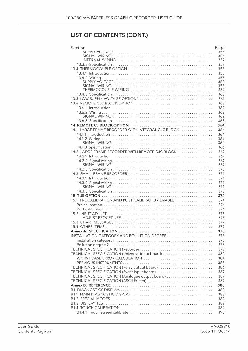
100/180 mm PAPERLESS GRAPHIC RECORDER: USER GUIDE
HA028910Issue 11 Oct 14
User GuideContents Page xii
SUPPLY VOLTAGE . . . . . . . . . . . . . . . . . . . . . . . . . . . . . . . . . . . . . . . . . . . . . . . . . . . 356SIGNAL WIRING . . . . . . . . . . . . . . . . . . . . . . . . . . . . . . . . . . . . . . . . . . . . . . . . . . . . . 356INTERNAL WIRING . . . . . . . . . . . . . . . . . . . . . . . . . . . . . . . . . . . . . . . . . . . . . . . . . . 357
13.3.3 Specifi cation . . . . . . . . . . . . . . . . . . . . . . . . . . . . . . . . . . . . . . . . . . . . . . . . . . . . 35713.4 THERMOCOUPLE OPTION . . . . . . . . . . . . . . . . . . . . . . . . . . . . . . . . . . . . . . . . . . . . 358
13.4.1 Introduction . . . . . . . . . . . . . . . . . . . . . . . . . . . . . . . . . . . . . . . . . . . . . . . . . . . . . 35813.4.2 Wiring . . . . . . . . . . . . . . . . . . . . . . . . . . . . . . . . . . . . . . . . . . . . . . . . . . . . . . . . . . 358
SUPPLY VOLTAGE . . . . . . . . . . . . . . . . . . . . . . . . . . . . . . . . . . . . . . . . . . . . . . . . . . . 358SIGNAL WIRING . . . . . . . . . . . . . . . . . . . . . . . . . . . . . . . . . . . . . . . . . . . . . . . . . . . . . 358THERMOCOUPLE WIRING . . . . . . . . . . . . . . . . . . . . . . . . . . . . . . . . . . . . . . . . . . . . 359
13.4.3 Specifi cation . . . . . . . . . . . . . . . . . . . . . . . . . . . . . . . . . . . . . . . . . . . . . . . . . . . . 36013.5 LOW SUPPLY VOLTAGE OPTION* . . . . . . . . . . . . . . . . . . . . . . . . . . . . . . . . . . . . . . . 36113.6 REMOTE CJC BLOCK OPTION . . . . . . . . . . . . . . . . . . . . . . . . . . . . . . . . . . . . . . . . . 362
13.6.1 Introduction . . . . . . . . . . . . . . . . . . . . . . . . . . . . . . . . . . . . . . . . . . . . . . . . . . . . . 36213.6.2 Wiring . . . . . . . . . . . . . . . . . . . . . . . . . . . . . . . . . . . . . . . . . . . . . . . . . . . . . . . . . . 362
SIGNAL WIRING . . . . . . . . . . . . . . . . . . . . . . . . . . . . . . . . . . . . . . . . . . . . . . . . . . . . . 36213.6.3 Specifi cation . . . . . . . . . . . . . . . . . . . . . . . . . . . . . . . . . . . . . . . . . . . . . . . . . . . . 363
14 REMOTE CJ BLOCK OPTION . . . . . . . . . . . . . . . . . . . . . . . . . . . . . . . . . . . . . . . . . . . . 36414.1 LARGE FRAME RECORDER WITH INTEGRAL CJC BLOCK . . . . . . . . . . . . . . . . . 364
14.1.1 Introduction . . . . . . . . . . . . . . . . . . . . . . . . . . . . . . . . . . . . . . . . . . . . . . . . . . . . . 36414.1.2 Wiring . . . . . . . . . . . . . . . . . . . . . . . . . . . . . . . . . . . . . . . . . . . . . . . . . . . . . . . . . . 364
SIGNAL WIRING . . . . . . . . . . . . . . . . . . . . . . . . . . . . . . . . . . . . . . . . . . . . . . . . . . . . . 36414.1.3 Specifi cation . . . . . . . . . . . . . . . . . . . . . . . . . . . . . . . . . . . . . . . . . . . . . . . . . . . . . 366
14.2 LARGE FRAME RECORDER WITH REMOTE CJC BLOCK . . . . . . . . . . . . . . . . . . . 36714.2.1 Introduction . . . . . . . . . . . . . . . . . . . . . . . . . . . . . . . . . . . . . . . . . . . . . . . . . . . . . 36714.2.2 Signal wiring . . . . . . . . . . . . . . . . . . . . . . . . . . . . . . . . . . . . . . . . . . . . . . . . . . . . 367
SIGNAL WIRING . . . . . . . . . . . . . . . . . . . . . . . . . . . . . . . . . . . . . . . . . . . . . . . . . . . . . 36714.2.3 Specifi cation . . . . . . . . . . . . . . . . . . . . . . . . . . . . . . . . . . . . . . . . . . . . . . . . . . . . 370
14.3 SMALL FRAME RECORDER . . . . . . . . . . . . . . . . . . . . . . . . . . . . . . . . . . . . . . . . . . . . 37114.3.1 Introduction . . . . . . . . . . . . . . . . . . . . . . . . . . . . . . . . . . . . . . . . . . . . . . . . . . . . . 37114.3.2 Signal wiring . . . . . . . . . . . . . . . . . . . . . . . . . . . . . . . . . . . . . . . . . . . . . . . . . . . . 371
SIGNAL WIRING . . . . . . . . . . . . . . . . . . . . . . . . . . . . . . . . . . . . . . . . . . . . . . . . . . . . . 37114.3.3 Specifi cation . . . . . . . . . . . . . . . . . . . . . . . . . . . . . . . . . . . . . . . . . . . . . . . . . . . . 373
15 TUS OPTION . . . . . . . . . . . . . . . . . . . . . . . . . . . . . . . . . . . . . . . . . . . . . . . . . . . . . . . . . . 37415.1 PRE CALIBRATION AND POST CALIBRATION ENABLE . . . . . . . . . . . . . . . . . . . . 374
Pre calibration . . . . . . . . . . . . . . . . . . . . . . . . . . . . . . . . . . . . . . . . . . . . . . . . . . . . . . . . . 374Post calibration . . . . . . . . . . . . . . . . . . . . . . . . . . . . . . . . . . . . . . . . . . . . . . . . . . . . . . . . . 374
15.2 INPUT ADJUST . . . . . . . . . . . . . . . . . . . . . . . . . . . . . . . . . . . . . . . . . . . . . . . . . . . . . . . 375ADJUST PROCEDURE . . . . . . . . . . . . . . . . . . . . . . . . . . . . . . . . . . . . . . . . . . . . . . . . 376
15.3 CHART MESSAGES . . . . . . . . . . . . . . . . . . . . . . . . . . . . . . . . . . . . . . . . . . . . . . . . . . . 37715.4 OTHER ITEMS . . . . . . . . . . . . . . . . . . . . . . . . . . . . . . . . . . . . . . . . . . . . . . . . . . . . . . . . 377Annex A: SPECIFICATION . . . . . . . . . . . . . . . . . . . . . . . . . . . . . . . . . . . . . . . . . . . . . . . . . 378INSTALLATION CATEGORY AND POLLUTION DEGREE . . . . . . . . . . . . . . . . . . . . . . . . 378
Installation category II . . . . . . . . . . . . . . . . . . . . . . . . . . . . . . . . . . . . . . . . . . . . . . . . . . 378Pollution degree 2 . . . . . . . . . . . . . . . . . . . . . . . . . . . . . . . . . . . . . . . . . . . . . . . . . . . . . . 378
TECHNICAL SPECIFICATION (Recorder) . . . . . . . . . . . . . . . . . . . . . . . . . . . . . . . . . . . . . 379TECHNICAL SPECIFICATION (Universal input board) . . . . . . . . . . . . . . . . . . . . . . . . . . 382
WORST CASE ERROR CALCULATION . . . . . . . . . . . . . . . . . . . . . . . . . . . . . . . . . . . . 384PREVIOUS INSTRUMENTS . . . . . . . . . . . . . . . . . . . . . . . . . . . . . . . . . . . . . . . . . . . . . . . 385
TECHNICAL SPECIFICATION (Relay output board) . . . . . . . . . . . . . . . . . . . . . . . . . . . . 386TECHNICAL SPECIFICATION (Event input board) . . . . . . . . . . . . . . . . . . . . . . . . . . . . . . 387TECHNICAL SPECIFICATION (Analogue output board) . . . . . . . . . . . . . . . . . . . . . . . . 387TECHNICAL SPECIFICATION (ASCII Printer) . . . . . . . . . . . . . . . . . . . . . . . . . . . . . . . . . . 387Annex B: REFERENCE . . . . . . . . . . . . . . . . . . . . . . . . . . . . . . . . . . . . . . . . . . . . . . . . . . . . . 388B1 DIAGNOSTICS DISPLAY . . . . . . . . . . . . . . . . . . . . . . . . . . . . . . . . . . . . . . . . . . . . . . . . . 388B1.1 MAIN DIAGNOSTIC DISPLAY . . . . . . . . . . . . . . . . . . . . . . . . . . . . . . . . . . . . . . . . . . . 388B1.2 SPECIAL MODES . . . . . . . . . . . . . . . . . . . . . . . . . . . . . . . . . . . . . . . . . . . . . . . . . . . . . 389B1.3 DISPLAY TEST . . . . . . . . . . . . . . . . . . . . . . . . . . . . . . . . . . . . . . . . . . . . . . . . . . . . . . . . 389B1.4 TOUCH CALIBRATION . . . . . . . . . . . . . . . . . . . . . . . . . . . . . . . . . . . . . . . . . . . . . . . . 389
B1.4.1 Touch screen calibrate . . . . . . . . . . . . . . . . . . . . . . . . . . . . . . . . . . . . . . . . . . . . 390
LIST OF CONTENTS (CONT.)
Section Page
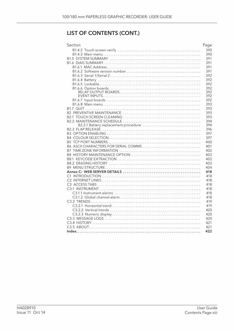
100/180 mm PAPERLESS GRAPHIC RECORDER: USER GUIDE
User GuideContents Page xiii
HA028910Issue 11 Oct 14
B1.4.2 Touch screen verify . . . . . . . . . . . . . . . . . . . . . . . . . . . . . . . . . . . . . . . . . . . . . . 390B1.4.3 Main menu . . . . . . . . . . . . . . . . . . . . . . . . . . . . . . . . . . . . . . . . . . . . . . . . . . . . . . 390
B1.5 SYSTEM SUMMARY . . . . . . . . . . . . . . . . . . . . . . . . . . . . . . . . . . . . . . . . . . . . . . . . . . 391B1.6 DIAG SUMMARY . . . . . . . . . . . . . . . . . . . . . . . . . . . . . . . . . . . . . . . . . . . . . . . . . . . . . . 391
B1.6.1 MAC Address . . . . . . . . . . . . . . . . . . . . . . . . . . . . . . . . . . . . . . . . . . . . . . . . . . . . 391B1.6.2 Software version number . . . . . . . . . . . . . . . . . . . . . . . . . . . . . . . . . . . . . . . . . 391B1.6.3 Serial 1/Serial 2 . . . . . . . . . . . . . . . . . . . . . . . . . . . . . . . . . . . . . . . . . . . . . . . . . . 392B1.6.4 Battery . . . . . . . . . . . . . . . . . . . . . . . . . . . . . . . . . . . . . . . . . . . . . . . . . . . . . . . . . 392B1.6.5 Lockable . . . . . . . . . . . . . . . . . . . . . . . . . . . . . . . . . . . . . . . . . . . . . . . . . . . . . . . . 392B1.6.6 Option boards . . . . . . . . . . . . . . . . . . . . . . . . . . . . . . . . . . . . . . . . . . . . . . . . . . . 392
RELAY OUTPUT BOARDS . . . . . . . . . . . . . . . . . . . . . . . . . . . . . . . . . . . . . . . . . . . . . 392EVENT INPUTS . . . . . . . . . . . . . . . . . . . . . . . . . . . . . . . . . . . . . . . . . . . . . . . . . . . . . . 392
B1.6.7 Input boards . . . . . . . . . . . . . . . . . . . . . . . . . . . . . . . . . . . . . . . . . . . . . . . . . . . . 392B1.6.8 Main menu . . . . . . . . . . . . . . . . . . . . . . . . . . . . . . . . . . . . . . . . . . . . . . . . . . . . . . 393
B1.7 QUIT . . . . . . . . . . . . . . . . . . . . . . . . . . . . . . . . . . . . . . . . . . . . . . . . . . . . . . . . . . . . . . . . 393B2 PREVENTIVE MAINTENANCE . . . . . . . . . . . . . . . . . . . . . . . . . . . . . . . . . . . . . . . . . . . . 393B2.1 TOUCH SCREEN CLEANING . . . . . . . . . . . . . . . . . . . . . . . . . . . . . . . . . . . . . . . . . . . 393B2.2 MAINTENANCE SCHEDULE . . . . . . . . . . . . . . . . . . . . . . . . . . . . . . . . . . . . . . . . . . . 394
B2.2.1 Battery replacement procedure . . . . . . . . . . . . . . . . . . . . . . . . . . . . . . . . . 394B2.3 FLAP RELEASE . . . . . . . . . . . . . . . . . . . . . . . . . . . . . . . . . . . . . . . . . . . . . . . . . . . . . . . 396B3 OPTION ENABLING . . . . . . . . . . . . . . . . . . . . . . . . . . . . . . . . . . . . . . . . . . . . . . . . . . . . 397B4 COLOUR SELECTION . . . . . . . . . . . . . . . . . . . . . . . . . . . . . . . . . . . . . . . . . . . . . . . . . . . 397B5 TCP PORT NUMBERS . . . . . . . . . . . . . . . . . . . . . . . . . . . . . . . . . . . . . . . . . . . . . . . . . . . 400B6 ASCII CHARACTERS FOR SERIAL COMMS . . . . . . . . . . . . . . . . . . . . . . . . . . . . . . . . 401B7 TIME ZONE INFORMATION . . . . . . . . . . . . . . . . . . . . . . . . . . . . . . . . . . . . . . . . . . . . . 402B8 HISTORY MAINTENANCE OPTION . . . . . . . . . . . . . . . . . . . . . . . . . . . . . . . . . . . . . . . 403B8.1 KEYCODE EXTRACTION . . . . . . . . . . . . . . . . . . . . . . . . . . . . . . . . . . . . . . . . . . . . . . 403B8.2 ERASING HISTORY . . . . . . . . . . . . . . . . . . . . . . . . . . . . . . . . . . . . . . . . . . . . . . . . . . . 403B9 MENU STRUCTURE . . . . . . . . . . . . . . . . . . . . . . . . . . . . . . . . . . . . . . . . . . . . . . . . . . . . . 404Annex C: WEB SERVER DETAILS . . . . . . . . . . . . . . . . . . . . . . . . . . . . . . . . . . . . . . . . . . . 418C1 INTRODUCTION . . . . . . . . . . . . . . . . . . . . . . . . . . . . . . . . . . . . . . . . . . . . . . . . . . . . . . . 418C2 INTERNET LINKS . . . . . . . . . . . . . . . . . . . . . . . . . . . . . . . . . . . . . . . . . . . . . . . . . . . . . . . 418C3 ACCESS TABS . . . . . . . . . . . . . . . . . . . . . . . . . . . . . . . . . . . . . . . . . . . . . . . . . . . . . . . . . 418C3.1 INSTRUMENT . . . . . . . . . . . . . . . . . . . . . . . . . . . . . . . . . . . . . . . . . . . . . . . . . . . . . . . . 418
C3.1.1 Instrument alarms . . . . . . . . . . . . . . . . . . . . . . . . . . . . . . . . . . . . . . . . . . . . . . . . 418C3.1.2 Global channel alarm . . . . . . . . . . . . . . . . . . . . . . . . . . . . . . . . . . . . . . . . . . . . . 418
C3.2 TRENDS . . . . . . . . . . . . . . . . . . . . . . . . . . . . . . . . . . . . . . . . . . . . . . . . . . . . . . . . . . . . . 419C3.2.1 Horizontal trend . . . . . . . . . . . . . . . . . . . . . . . . . . . . . . . . . . . . . . . . . . . . . . . . . 419C3.2.2 Vertical trends . . . . . . . . . . . . . . . . . . . . . . . . . . . . . . . . . . . . . . . . . . . . . . . . . . 420C3.2.3 Numeric display . . . . . . . . . . . . . . . . . . . . . . . . . . . . . . . . . . . . . . . . . . . . . . . . . 420
C3.3 MESSAGE LOGS . . . . . . . . . . . . . . . . . . . . . . . . . . . . . . . . . . . . . . . . . . . . . . . . . . . . . 420C3.4 HISTORY . . . . . . . . . . . . . . . . . . . . . . . . . . . . . . . . . . . . . . . . . . . . . . . . . . . . . . . . . . . . 421C3.5 ABOUT . . . . . . . . . . . . . . . . . . . . . . . . . . . . . . . . . . . . . . . . . . . . . . . . . . . . . . . . . . . . . . 421Index . . . . . . . . . . . . . . . . . . . . . . . . . . . . . . . . . . . . . . . . . . . . . . . . . . . . . . . . . . . . . . . . . . . . . 422
LIST OF CONTENTS (CONT.)
Section Page

100/180 mm PAPERLESS GRAPHIC RECORDER: USER GUIDE
HA028910Issue 11 Oct 14
User GuideContents Page xiv
This page is deliberately left blank

100/180 mm PAPERLESS GRAPHIC RECORDER: USER GUIDE
User GuidePage 1
HA028910Issue 11 Oct 14
SAFETY NOTES
WARNINGAny interruption of the protective conductor inside or outside the apparatus, or disconnection of the protective earth terminal is likely to make the apparatus dangerous under some fault condi-tions. Intentional interruption is prohibited.
Note: in order to comply with the requirements of safety standard BS EN61010, the recorder shall have one of the following as a disconnecting device, fi tted within easy reach of the operator, and labelled as the disconnecting device.a. A switch or circuit breaker which complies with the requirements of IEC947-1 and IEC947-3b. A separable coupler which can be disconnected without the use of a toolc. A separable plug, without a locking device, to mate with a socket outlet in the building.
1. Before any other connection is made, the protective earth terminal shall be connected to a protec-tive conductor. The mains (supply voltage) wiring must be terminated within the connector in such a way that, should it slip in the cable clamp, the Earth wire would be the last wire to become discon-nected.
2. In the case of portable equipment, the protective earth terminal must remain connected (even if the recorder is isolated from the mains supply), if any of the I/O circuits are connected to hazardous volt-ages*.
3. The mains supply fuse within the power supply is not replaceable. If it is suspected that the fuse is faulty, the manufacturer’s local service centre should be contacted for advice.
4. Whenever it is likely that protection has been impaired, the unit shall be made inoperative, and se-cured against accidental operation. The manufacturer’s nearest service centre should be contacted for advice.
5. Any adjustment, maintenance and repair of the opened apparatus under voltage, should be avoided as far as possible and, if inevitable, shall be carried out only by a skilled person who is aware of the hazard involved.
6. Where conductive pollution (e.g. condensation, carbon dust) is likely, adequate air conditioning/fi l-tering/sealing etc. must be installed in the recorder enclosure.
7. Signal and supply voltage wiring should be kept separate from one another. Where this is impracti-cal, shielded cables should be used for the signal wiring.
8. If the equipment is used in a manner not specifi ed by the manufacturer, the protection provided by the equipment might be impaired.
* A full defi nition of ‘Hazardous’ voltages appears under ‘Hazardous live’ in BS EN61010. Briefl y, under normal operating conditions, hazardous voltages are defi ned as being > 30V RMS (42.2V peak) or > 60V dc.
SYMBOLS USED ON THE RECORDER LABELLING
One or more of the symbols below may appear as a part of the recorder labelling.
! Refer to the manual for instructions
Protective earth
This recorder for ac supply only
This recorder for dc supply only
This recorder for either ac or dc supply
Risk of electric shock
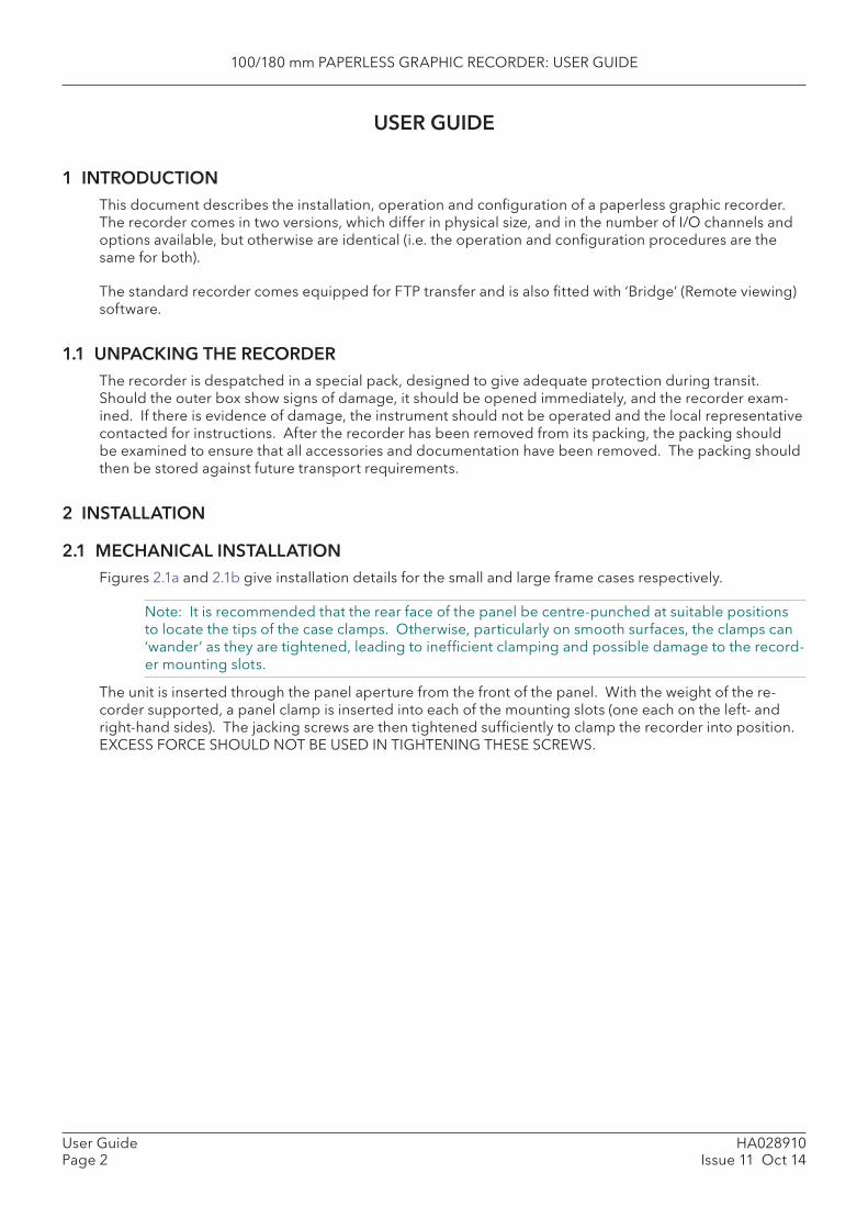
100/180 mm PAPERLESS GRAPHIC RECORDER: USER GUIDE
HA028910Issue 11 Oct 14
User GuidePage 2
USER GUIDE
1 INTRODUCTIONThis document describes the installation, operation and confi guration of a paperless graphic recorder. The recorder comes in two versions, which differ in physical size, and in the number of I/O channels and options available, but otherwise are identical (i.e. the operation and confi guration procedures are the same for both).
The standard recorder comes equipped for FTP transfer and is also fi tted with ‘Bridge’ (Remote viewing) software.
1.1 UNPACKING THE RECORDERThe recorder is despatched in a special pack, designed to give adequate protection during transit. Should the outer box show signs of damage, it should be opened immediately, and the recorder exam-ined. If there is evidence of damage, the instrument should not be operated and the local representative contacted for instructions. After the recorder has been removed from its packing, the packing should be examined to ensure that all accessories and documentation have been removed. The packing should then be stored against future transport requirements.
2 INSTALLATION
2.1 MECHANICAL INSTALLATION Figures 2.1a and 2.1b give installation details for the small and large frame cases respectively.
Note: It is recommended that the rear face of the panel be centre-punched at suitable positions to locate the tips of the case clamps. Otherwise, particularly on smooth surfaces, the clamps can ‘wander’ as they are tightened, leading to ineffi cient clamping and possible damage to the record-er mounting slots.
The unit is inserted through the panel aperture from the front of the panel. With the weight of the re-corder supported, a panel clamp is inserted into each of the mounting slots (one each on the left- and right-hand sides). The jacking screws are then tightened suffi ciently to clamp the recorder into position. EXCESS FORCE SHOULD NOT BE USED IN TIGHTENING THESE SCREWS.
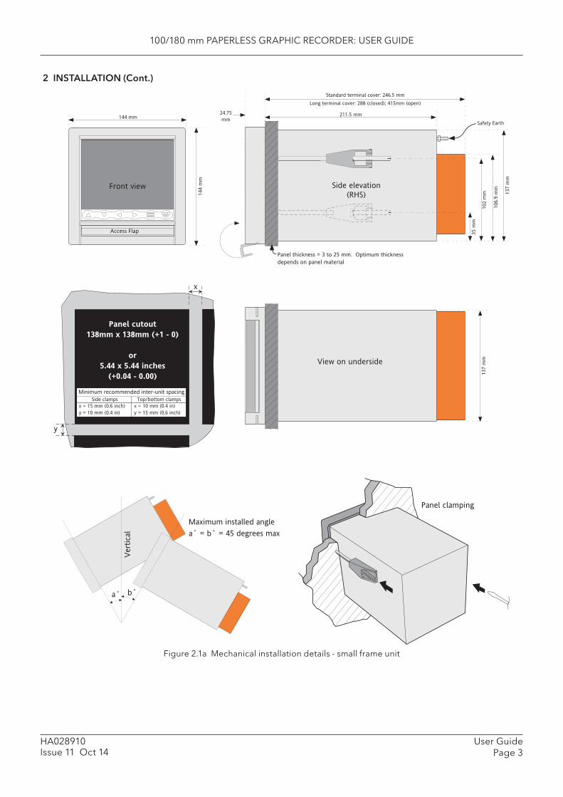
100/180 mm PAPERLESS GRAPHIC RECORDER: USER GUIDE
User GuidePage 3
HA028910Issue 11 Oct 14
2 INSTALLATION (Cont.)
Figure 2.1a Mechanical installation details - small frame unit
a˚ b˚
Vert
ical
Maximum installed angle
a˚ = b˚ = 45 degrees max
Panel cutout
138mm x 138mm (+1 - 0)
or
5.44 x 5.44 inches
(+0.04 - 0.00)
y
x = 15 mm (0.6 inch)
y = 10 mm (0.4 in)
Minimum recommended inter-unit spacing
Side clamps Top/bottom clamps
x = 10 mm (0.4 in)
y = 15 mm (0.6 inch)
x
Front view
144 mm
Access Flap
144 m
m
Side elevation
(RHS)
View on underside
137 m
m
Panel clamping
211.5 mm
Standard terminal cover: 246.5 mm
Long terminal cover: 288 (closed); 415mm (open)
24.75
mm
35 m
m
102 m
m
106.9
mm
137 m
m
Panel thickness = 3 to 25 mm. Optimum thickness
depends on panel material
Safety Earth
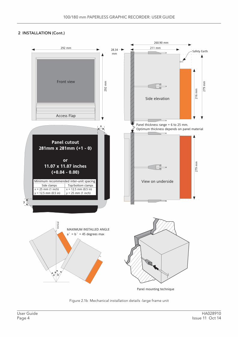
100/180 mm PAPERLESS GRAPHIC RECORDER: USER GUIDE
HA028910Issue 11 Oct 14
User GuidePage 4
2 INSTALLATION (Cont.)
Figure 2.1b Mechanical installation details -large frame unit
Vert
ical
MAXIMUM INSTALLED ANGLE
a˚ = b˚ = 45 degrees max
a b
Side elevation
View on underside
Panel cutout
281mm x 281mm (+1 - 0)
or
11.07 x 11.07 inches
(+0.04 - 0.00)
x
y
292 mm
292 m
mFront view
Access Flap
211 mm
260.90 mm
28.34
mm
279 m
m
216 m
m279 m
m
Panel mounting technique
x = 25 mm (1 inch)
y = 12.5 mm (0.5 in)
Minimum recommended inter-unit spacing
Side clamps Top/bottom clamps
x = 12.5 mm (0.5 in)
y = 25 mm (1 inch)
Panel thickness range = 6 to 25 mm.
Optimum thickness depends on panel material
Safety Earth
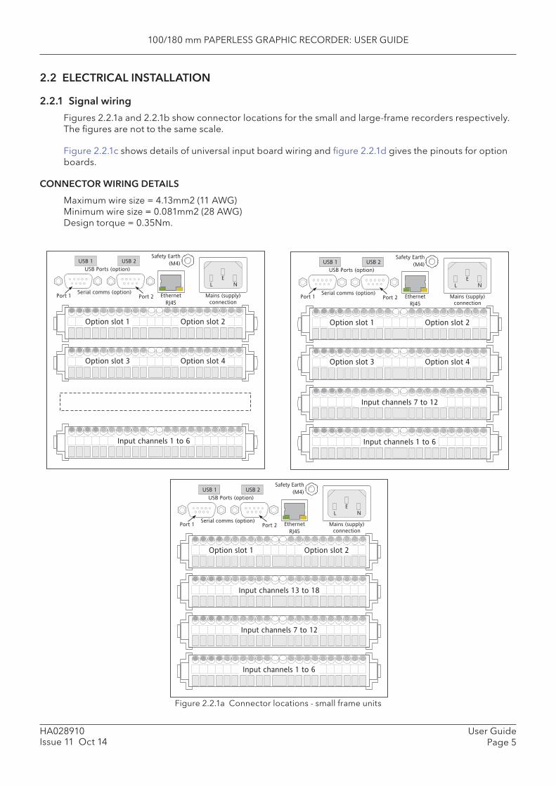
100/180 mm PAPERLESS GRAPHIC RECORDER: USER GUIDE
User GuidePage 5
HA028910Issue 11 Oct 14
2.2 ELECTRICAL INSTALLATION
2.2.1 Signal wiring
Figures 2.2.1a and 2.2.1b show connector locations for the small and large-frame recorders respectively. The fi gures are not to the same scale.
Figure 2.2.1c shows details of universal input board wiring and fi gure 2.2.1d gives the pinouts for option boards.
CONNECTOR WIRING DETAILS
Maximum wire size = 4.13mm2 (11 AWG)Minimum wire size = 0.081mm2 (28 AWG) Design torque = 0.35Nm.
Figure 2.2.1a Connector locations - small frame units
Ethernet
RJ45
Safety Earth
(M4)
Serial comms (option)
USB Ports (option)
USB 1 USB 2
Port 1 Port 2
L N
E
Mains (supply)
connection
Input channels 1 to 6
Option slot 1 Option slot 2
Option slot 3 Option slot 4
L N
E
Mains (supply)
connection
Input channels 1 to 6
Option slot 1 Option slot 2
Option slot 3 Option slot 4
Input channels 7 to 12
Serial comms (option)
USB Ports (option)
USB 1 USB 2
Port 1 Port 2 Ethernet
RJ45
Safety Earth
(M4)
L N
E
Mains (supply)
connection
Input channels 1 to 6
Option slot 1 Option slot 2
Input channels 7 to 12
Input channels 13 to 18
Serial comms (option)
USB Ports (option)
USB 1 USB 2
Port 1 Port 2 Ethernet
RJ45
Safety Earth
(M4)

100/180 mm PAPERLESS GRAPHIC RECORDER: USER GUIDE
HA028910Issue 11 Oct 14
User GuidePage 6
2.2.1 SIGNAL WIRING (Cont.)
Figure 2.2.1b Connector locations - large frame units
Input channels 1 to 7
Input channels 1 to 6
Input channels 7 to 12
Input channels 1 to 7
Input channels 13 to 18
Input channels 19 to 24
Input channels 1 to 7
Input channels 25 to 30
Input channels 31 to 36
Input channels 1 to 7
Input channels 37 to 42
Input channels 43 to 48
Option board 3 Option board 4
Option board 1 Option board 2
Not used Option board 9
Option board 7 Option board 8
Option board 5 Option board 6
Serial comms (option)
L N
E
Mains (supply)
connection
USB Ports (option)
Ethernet
RJ45
USB1 USB2Port 1 Port 2
Safety Earth
(M4)
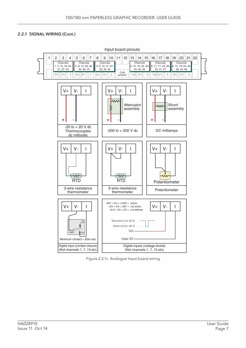
100/180 mm PAPERLESS GRAPHIC RECORDER: USER GUIDE
User GuidePage 7
HA028910Issue 11 Oct 14
2.2.1 SIGNAL WIRING (Cont.)
Figure 2.2.1c Analogue Input board wiring
com
nc
no
V+ V- I
Digital input (contact closure)(Not channels 1, 7, 13 etc)
Minimum contact = 60m sec
V+ V- I
Potentiometer
Potentiometer
V+ V- I
2-wire resistancethermometer
RTD
V+ V- I
3-wire resistancethermometer
RTD
Not active (2 to 30 V)
Active (0.8 to -30 V)
Digital inputs (voltage levels)(Not channels 1, 7, 13 etc)
V+ V- I-30V < Vin < +0.8V = active
+2V < Vin < 30V = not active+0.8 < Vin < 2V = not defined
Vin
User 0V
V+ V- I
+ - + -
Shuntassembly
V+ V- I
+ -
V+ V- I
Attenuatorassembly
-200 to + 200 V dc-20 to + 20 V dcThermocouples
dc millivoltsDC milliamps
1 2 3 4 5 6 7 8 9 10 11 12 13 14 15 16 17 18 19 20 21 22
V+ Coldjunction
Input board pinouts
Channels1, 7, 13, 19, 25,
31, 37, 43
Channels2, 8, 14, 20, 26,
32, 38, 44
Channels3, 9, 15, 21, 27,
33, 39, 45
Channels4, 10, 16, 22, 28,
34, 40, 46
Channels5, 11, 17, 23, 29,
35, 41, 47
Channels6, 12, 18, 24, 30,
36, 42, 48
V- I V+ V- I V+ V- I V+ V- I V+ V- I V+ V- I
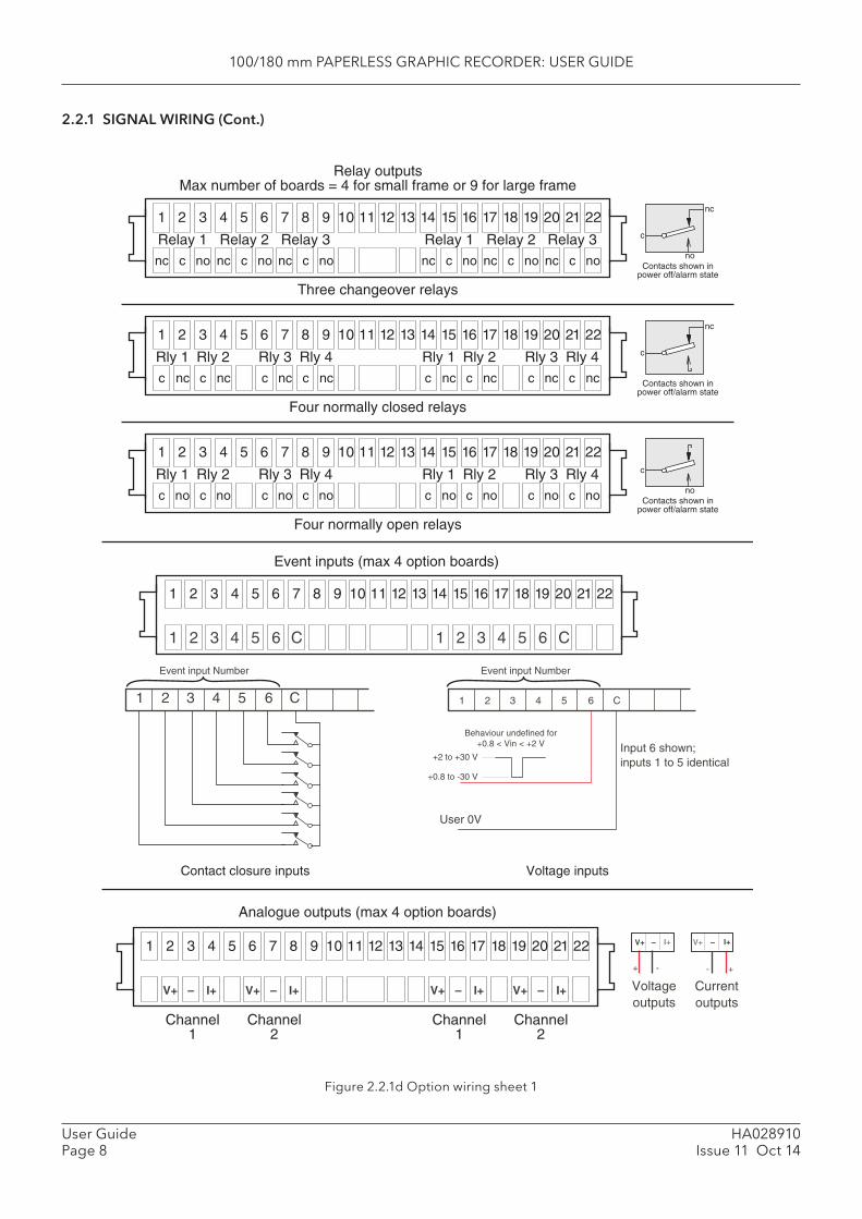
100/180 mm PAPERLESS GRAPHIC RECORDER: USER GUIDE
HA028910Issue 11 Oct 14
User GuidePage 8
2.2.1 SIGNAL WIRING (Cont.)
Figure 2.2.1d Option wiring sheet 1
1 2 3 4 5 6 7 8 9 10 11 12 13 14 15 16 17 18 19 20 21 22
Relay 1nc c no
Relay 2nc c no
Relay 3nc c no
Relay 1nc c no
Relay 2nc c no
Relay 3nc c no
c
nc
noContacts shown in
power off/alarm state
Three changeover relays
1 2 3 4 5 6 7 8 9 10 11 12 13 14 15 16 17 18 19 20 21 22
Rly 1c c
Rly 2nc c
Rly 3nc c ncnc
Rly 4 c
nc
Contacts shown inpower off/alarm state
Four normally closed relays
Rly 1c c
Rly 2nc c
Rly 3nc c ncnc
Rly 4
1 2 3 4 5 6 7 8 9 10 11 12 13 14 15 16 17 18 19 20 21 22
Rly 1c c
Rly 2no c
Rly 3no c nono
Rly 4
Four normally open relays
Rly 1c c
Rly 2no c
Rly 3no c nono
Rly 4 c
noContacts shown in
power off/alarm state
Relay outputsMax number of boards = 4 for small frame or 9 for large frame
1 2 3 4 5 6 7 8 9 10 11 12 13 14 15 16 17 18 19 20 21 22
1 2 3 4 5 6 C 1 2 3 4 5 6 C
Event inputs (max 4 option boards)
Event input Number
C1 2 3 4 5 6
+2 to +30 V
+0.8 to -30 V
User 0V
Input 6 shown;inputs 1 to 5 identical
Event input Number
C1 2 3 4 5 6
Voltage inputsContact closure inputs
Voltageoutputs
+ -
V+ – I+
+-
Currentoutputs
V+ – I+1 2 3 4 5 6 7 8 9 10 11 12 13 14 15 16 17 18 19 20 21 22
V+ – I+ V+ – I+ V+ – I+ V+ – I+
Channel1
Channel2
Channel1
Channel2
Analogue outputs (max 4 option boards)
Behaviour undefined for+0.8 < Vin < +2 V
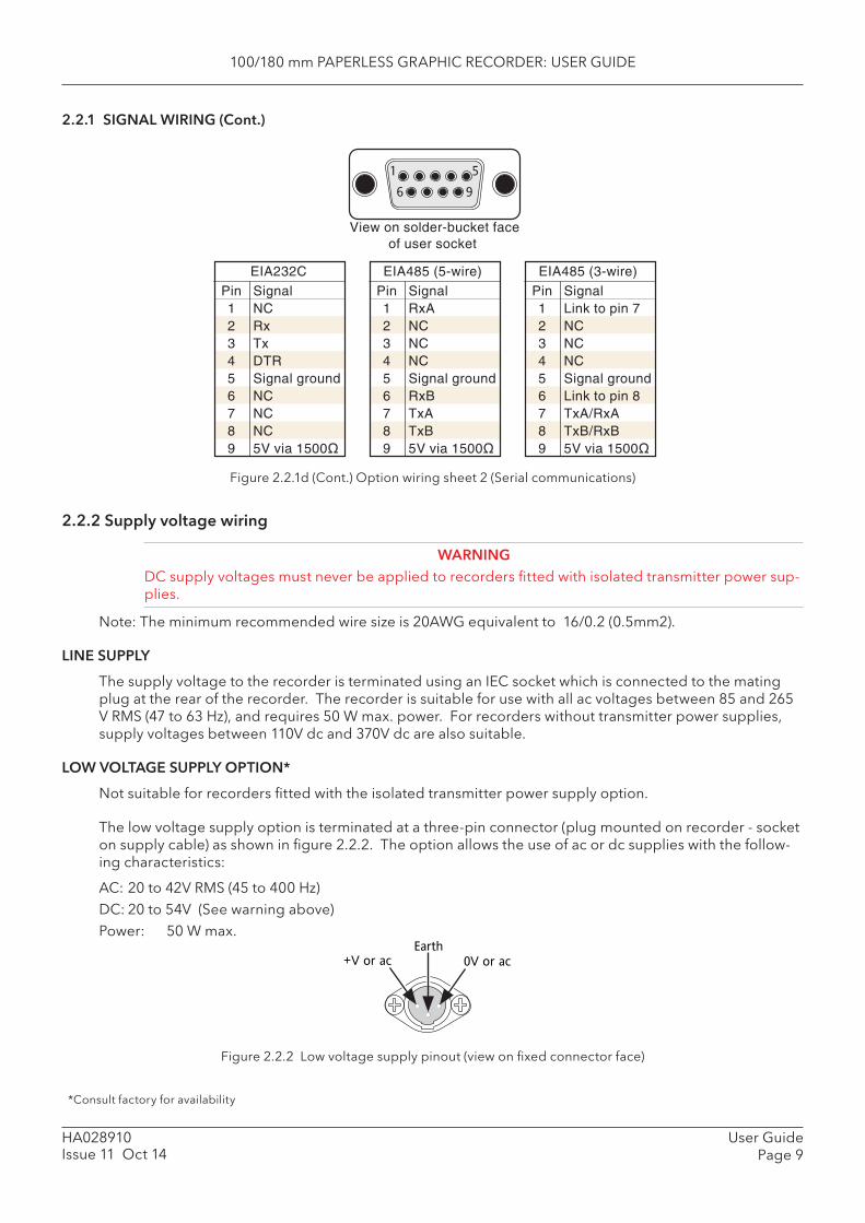
100/180 mm PAPERLESS GRAPHIC RECORDER: USER GUIDE
User GuidePage 9
HA028910Issue 11 Oct 14
2.2.1 SIGNAL WIRING (Cont.)
Figure 2.2.1d (Cont.) Option wiring sheet 2 (Serial communications)
2.2.2 Supply voltage wiring
WARNINGDC supply voltages must never be applied to recorders fi tted with isolated transmitter power sup-plies.
Note: The minimum recommended wire size is 20AWG equivalent to 16/0.2 (0.5mm2).
LINE SUPPLY
The supply voltage to the recorder is terminated using an IEC socket which is connected to the mating plug at the rear of the recorder. The recorder is suitable for use with all ac voltages between 85 and 265 V RMS (47 to 63 Hz), and requires 50 W max. power. For recorders without transmitter power supplies, supply voltages between 110V dc and 370V dc are also suitable.
LOW VOLTAGE SUPPLY OPTION*
Not suitable for recorders fi tted with the isolated transmitter power supply option.
The low voltage supply option is terminated at a three-pin connector (plug mounted on recorder - socket on supply cable) as shown in fi gure 2.2.2. The option allows the use of ac or dc supplies with the follow-ing characteristics:
AC: 20 to 42V RMS (45 to 400 Hz) DC: 20 to 54V (See warning above) Power: 50 W max.
EIA485 (5-wire)
Pin 1 2 3 4 5 6 7 8 9
Signal RxA NC NC NC Signal ground RxB TxA TxB
EIA232C
Pin 1 2 3 4 5 6 7 8 9
Signal NC Rx Tx DTR Signal ground NC NC NC
EIA485 (3-wire)
Pin 1 2 3 4 5 6 7 8 9
Signal Link to pin 7 NC NC NC Signal ground Link to pin 8 TxA/RxA TxB/RxB
1
6
5
9
View on solder-bucket face of user socket
Figure 2.2.2 Low voltage supply pinout (view on fi xed connector face)
+V or ac
Earth
0V or ac
*Consult factory for availability

100/180 mm PAPERLESS GRAPHIC RECORDER: USER GUIDE
HA028910Issue 11 Oct 14
User GuidePage 10
2.3 ACCESS FLAPNote: See also section 2.4 if the lockable fl ap option is fi tted. Lockable fl aps are identi-fi ed by means of a padlock symbol printed towards the right hand end of the fl ap label.
Figure 2.3 Access fl ap detail
The access fl ap is located immediately below the recorder screen. To open the fl ap, insert one or more fi ngers under the fl ap handle, and pull it outwards and down (fi gure 2.3). A lockable version of the fl ap is available - see section 2.4 for details. Located behind the fl ap are (from left to right):
1. a stylus (press to eject)2. a slot for a Compact Flash or Secure Digital (SD) card3. a USB port (usbfront).
USBFrontStylus storage
SD orCompact Flash
card
Door lock (option)
Stylusstorage
SD orCompact
Flash cardUSBFront
Door lock
(option)
a) Insert fi nger(s) and pull forwards and down (small frame) b) Behind fl ap details (small frame)
c) Insert fi nger(s) and pull forwards and down (large frame) d) Behind fl ap details (large frame)

100/180 mm PAPERLESS GRAPHIC RECORDER: USER GUIDE
User GuidePage 11
HA028910Issue 11 Oct 14
2.3.1 Stylus
A stylus suitable for use on the touch screen is located in a storage area to the left of the Compact Flash/SD Card slot.
2.3.2 Card slot
The slot for the Compact Flash or SD card is located centrally behind the fl ap. If an SD card is already fi tted, it is removed by pressing on the card, to unlatch it, then pulling the card out of the slot. If a Com-pact Flash card is already fi tted, it is removed by a double operation of the eject button. See details in fi gures 2.3.2a and 2.3.2b, below
CAUTIONRemoval of the memory device whilst archiving is in progress causes irreparable damage to the fi ling structure on the device, rendering it unusable. For this reason, archiving should be sus-pended (section 4.1) (wait for the green section of the disk icon (section 3.1.3) to go ‘white’) before the device is removed. It is strongly recommended that the ‘Remove Media’ facility described in section 3.1.4 (Summary menu) be used to ensure that it is safe to remove the memory device. For recorders fi tted with a lockable fl ap, see also section 2.4.
Figure 2.3.2a SD card details Figure 2.3.2b Compact Flash card details
LED INDICATORS
Three LED indicators are located above the card slot as shown in fi gure 2.3.2c, below.
SD card(Push in - Push out)
Eject button(Press twice)
CompactFlash card
Figure 2.3.2c indicating LEDs (SD card - Compact Flash card similar)
2.3.3 USB Front Port
A type-A USB socket is located to the right of the Compact Flash/SD Card slot. This port can be used to connect a mouse, a keyboard, a barcode scanner, a ‘memory stick’ or a fl oppy disk drive. If more than one such device is required at a time, two further, rear panel USB ports (USB 1 and USB 2) are available as an option. Maximum current per USB device = 500 mA.
Note: It is the responsibility of the user to establish the electromagnetic susceptibility of any USB peripheral connected to the recorder. Refer to the USB port specifi cation in Annex A for details.
Power/watchdog
LED (green)
Card activity
LED (yellow)
USBFront
Power LED (yellow)
Card slot
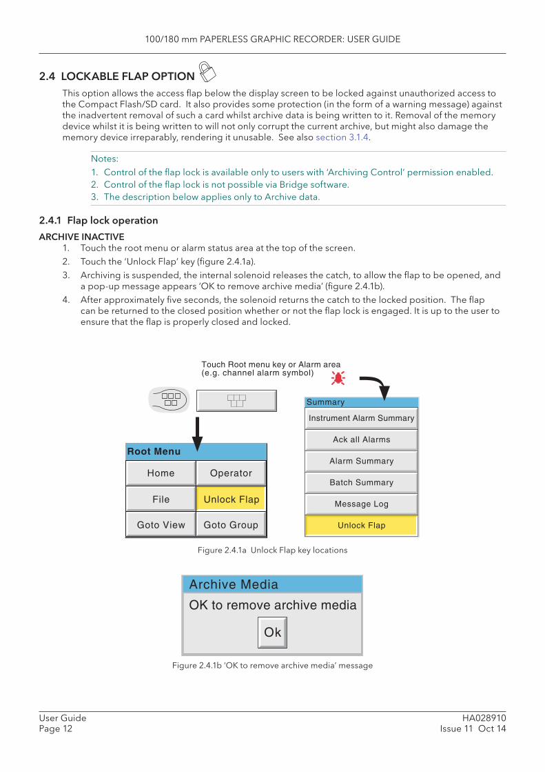
100/180 mm PAPERLESS GRAPHIC RECORDER: USER GUIDE
HA028910Issue 11 Oct 14
User GuidePage 12
2.4 LOCKABLE FLAP OPTION This option allows the access fl ap below the display screen to be locked against unauthorized access to the Compact Flash/SD card. It also provides some protection (in the form of a warning message) against the inadvertent removal of such a card whilst archive data is being written to it. Removal of the memory device whilst it is being written to will not only corrupt the current archive, but might also damage the memory device irreparably, rendering it unusable. See also section 3.1.4.
Notes:1. Control of the fl ap lock is available only to users with ‘Archiving Control’ permission enabled.2. Control of the fl ap lock is not possible via Bridge software.3. The description below applies only to Archive data.
2.4.1 Flap lock operation
ARCHIVE INACTIVE1. Touch the root menu or alarm status area at the top of the screen.2. Touch the ‘Unlock Flap’ key (fi gure 2.4.1a).3. Archiving is suspended, the internal solenoid releases the catch, to allow the fl ap to be opened, and
a pop-up message appears ‘OK to remove archive media’ (fi gure 2.4.1b).4. After approximately fi ve seconds, the solenoid returns the catch to the locked position. The fl ap
can be returned to the closed position whether or not the fl ap lock is engaged. It is up to the user to ensure that the fl ap is properly closed and locked.
Figure 2.4.1a Unlock Flap key locations
Figure 2.4.1b ‘ OK to remove archive media’ message
Touch Root menu key or Alarm area(e.g. channel alarm symbol)
Home Operator
File
Goto View Goto Group
Root Menu
Unlock Flap
Ack all Alarms
Alarm Summary
Batch Summary
Message Log
Unlock Flap
Instrument Alarm Summary
Summary
OK to remove archive media
Ok
Archive Media
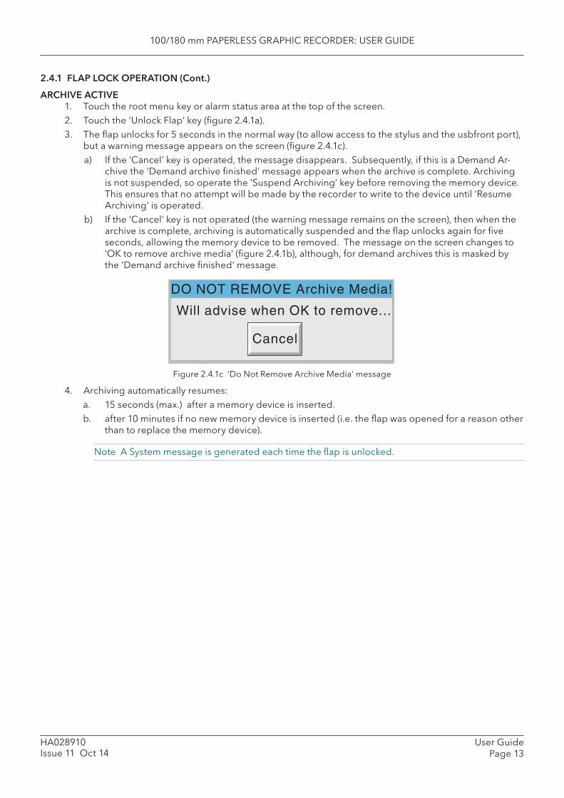
100/180 mm PAPERLESS GRAPHIC RECORDER: USER GUIDE
User GuidePage 13
HA028910Issue 11 Oct 14
2.4.1 FLAP LOCK OPERATION (Cont.)
ARCHIVE ACTIVE1. Touch the root menu key or alarm status area at the top of the screen.2. Touch the ‘Unlock Flap’ key (fi gure 2.4.1a).3. The fl ap unlocks for 5 seconds in the normal way (to allow access to the stylus and the usbfront port),
but a warning message appears on the screen (fi gure 2.4.1c). a) If the ‘Cancel’ key is operated, the message disappears. Subsequently, if this is a Demand Ar-
chive the ‘Demand archive fi nished’ message appears when the archive is complete. Archiving is not suspended, so operate the ‘Suspend Archiving’ key before removing the memory device. This ensures that no attempt will be made by the recorder to write to the device until ‘Resume Archiving’ is operated.
b) If the ‘Cancel’ key is not operated (the warning message remains on the screen), then when the archive is complete, archiving is automatically suspended and the fl ap unlocks again for fi ve seconds, allowing the memory device to be removed. The message on the screen changes to ‘OK to remove archive media’ (fi gure 2.4.1b), although, for demand archives this is masked by the ‘Demand archive fi nished’ message.
Figure 2.4.1c ‘ Do Not Remove Archive Media’ message
4. Archiving automatically resumes:a. 15 seconds (max.) after a memory device is inserted.b. after 10 minutes if no new memory device is inserted (i.e. the fl ap was opened for a reason other
than to replace the memory device).
Note A System message is generated each time the fl ap is unlocked.
Will advise when OK to remove...
Cancel
DO NOT REMOVE Archive Media!
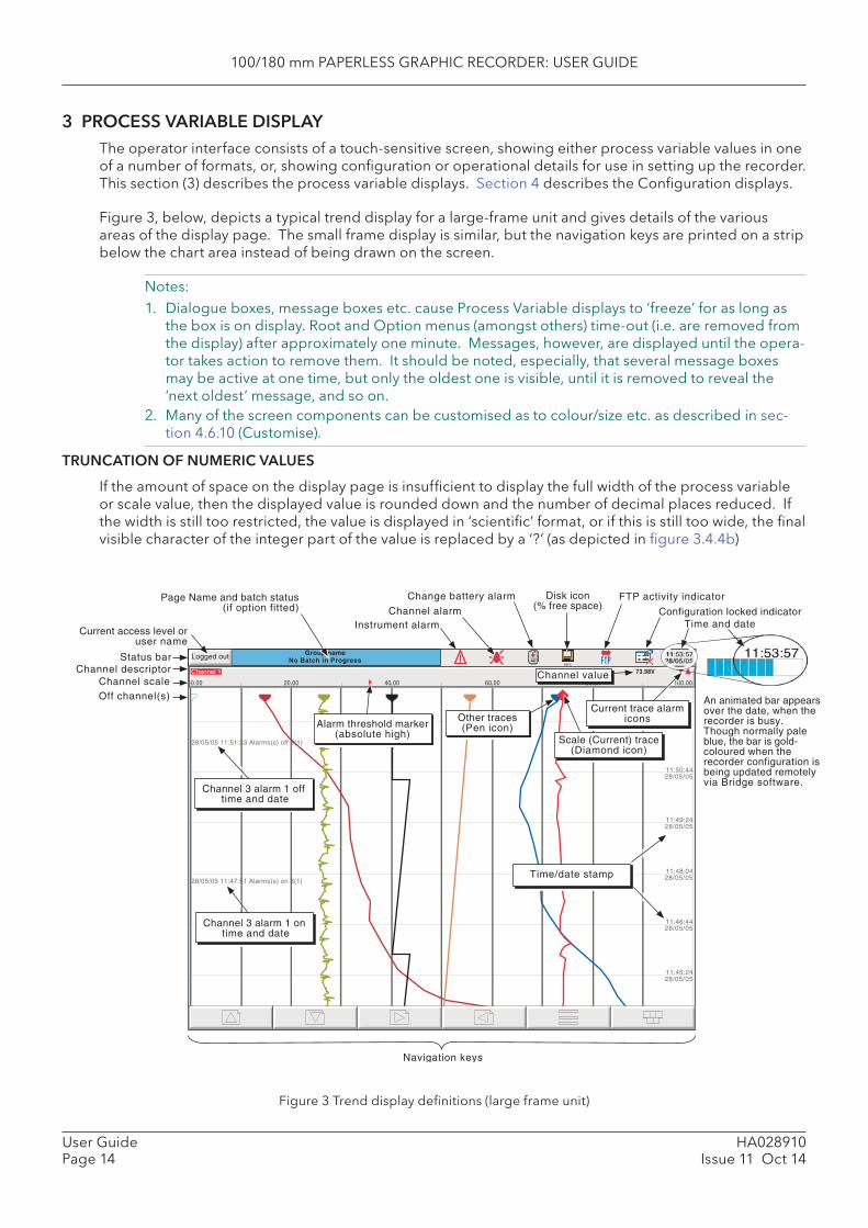
100/180 mm PAPERLESS GRAPHIC RECORDER: USER GUIDE
HA028910Issue 11 Oct 14
User GuidePage 14
3 PROCESS VARIABLE DISPLAYThe operator interface consists of a touch-sensitive screen, showing either process variable values in one of a number of formats, or, showing confi guration or operational details for use in setting up the recorder. This section (3) describes the process variable displays. Section 4 describes the Confi guration displays.
Figure 3, below, depicts a typical trend display for a large-frame unit and gives details of the various areas of the display page. The small frame display is similar, but the navigation keys are printed on a strip below the chart area instead of being drawn on the screen.
Notes: 1. Dialogue boxes, message boxes etc. cause Process Variable displays to ‘freeze’ for as long as
the box is on display. Root and Option menus (amongst others) time-out (i.e. are removed from the display) after approximately one minute. Messages, however, are displayed until the opera-tor takes action to remove them. It should be noted, especially, that several message boxes may be active at one time, but only the oldest one is visible, until it is removed to reveal the ‘next oldest’ message, and so on.
2. Many of the screen components can be customised as to colour/size etc. as described in sec-tion 4.6.10 (Customise).
TRUNCATION OF NUMERIC VALUES
If the amount of space on the display page is insuffi cient to display the full width of the process variable or scale value, then the displayed value is rounded down and the number of decimal places reduced. If the width is still too restricted, the value is displayed in ‘scientifi c’ format, or if this is still too wide, the fi nal visible character of the integer part of the value is replaced by a ‘?’ (as depicted in fi gure 3.4.4b)
Figure 3 Trend display defi nitions (large frame unit)
Channel 1
0.00
73.98V
100.0020.00 60.00 80.0040.00Channel value
99%
Group nameNo Batch in Progress
11:52:0428/01/04
11:49:2428/05/05
11:46:4428/05/05
28/05/05 11:47:51 Alarms(s) on 3(1)
28/05/05 11:51:33 Alarms(s) off 3(1)
Instrument alarmChannel alarm
Change battery alarm
Time and date
Scale (Current) trace(Diamond icon)
Other traces(Pen icon)
Channel scale
Time/date stamp
Off channel(s)
Logged out
Current access level oruser name
Status bar
Page Name and batch status(if option fitted)
FTP activity indicator
Current trace alarmicons
Channel 3 alarm 1 on time and date
Channel 3 alarm 1 off time and date
An animated bar appearsover the date, when therecorder is busy.Though normally paleblue, the bar is gold-coloured when therecorder configuration isbeing updated remotelyvia Bridge software.
Alarm threshold marker(absolute high)
Configuration locked indicator
Navigation keys
Disk icon(% free space)
Channel descriptor
11:48:0428/05/05
11:50:4428/05/05
11:45:2428/05/05
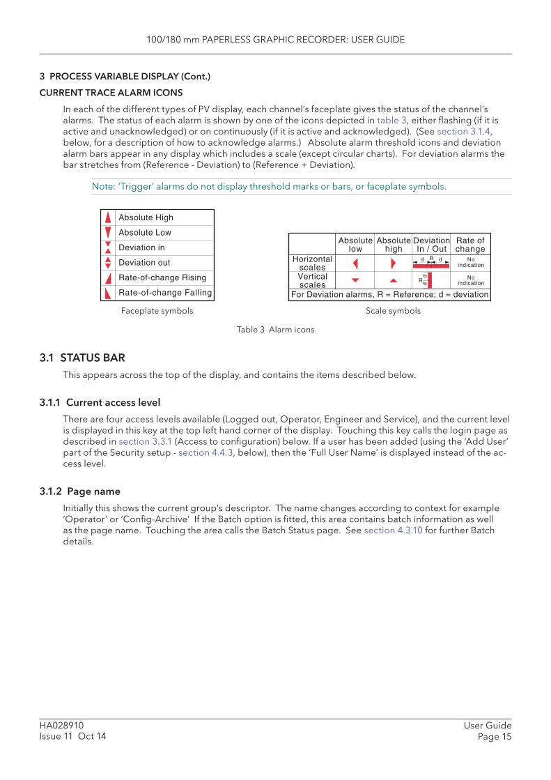
100/180 mm PAPERLESS GRAPHIC RECORDER: USER GUIDE
User GuidePage 15
HA028910Issue 11 Oct 14
3 PROCESS VARIABLE DISPLAY (Cont.)
CURRENT TRACE ALARM ICONS
In each of the different types of PV display, each channel’s faceplate gives the status of the channel’s alarms. The status of each alarm is shown by one of the icons depicted in table 3, either fl ashing (if it is active and unacknowledged) or on continuously (if it is active and acknowledged). (See section 3.1.4, below, for a description of how to acknowledge alarms.) Absolute alarm threshold icons and deviation alarm bars appear in any display which includes a scale (except circular charts). For deviation alarms the bar stretches from (Reference - Deviation) to (Reference + Deviation).
Note: ‘Trigger’ alarms do not display threshold marks or bars, or faceplate symbols.
Faceplate symbols
Absolute High
Absolute Low
Deviation in
Deviation out
Rate-of-change Rising
Rate-of-change Falling
Absolutelow
Absolutehigh
DeviationIn / Out
HorizontalscalesVerticalscales
Rate ofchange
Noindication
Noindication
Rd d
ddR
For Deviation alarms, R = Reference; d = deviation
Scale symbols
Table 3 Alarm icons
3.1 STATUS BARThis appears across the top of the display, and contains the items described below.
3.1.1 Current access level
There are four access levels available (Logged out, Operator, Engineer and Service), and the current level is displayed in this key at the top left hand corner of the display. Touching this key calls the login page as described in section 3.3.1 (Access to confi guration) below. If a user has been added (using the ‘Add User’ part of the Security setup - section 4.4.3, below), then the ‘Full User Name’ is displayed instead of the ac-cess level.
3.1.2 Page name
Initially this shows the current group’s descriptor. The name changes according to context for example ‘Operator’ or ‘Confi g-Archive’ If the Batch option is fi tted, this area contains batch information as well as the page name. Touching the area calls the Batch Status page. See section 4.3.10 for further Batch details.
100/180 mm PAPERLESS GRAPHIC RECORDER: USER GUIDE
HA028910Issue 11 Oct 14
User GuidePage 16
3.1.3 Alarm indication
This area of the display can contain a number of status icons: Instrument alarm, Channel alarm, Battery change, Disk status, FTP in progress, Confi guration locked, and so on. Pressing this area of the screen calls the ‘Summary menu’ (section 3.1.4) allowing the user to view active instrument alarms, to acknowl-edge all channel alarms, to display the Alarm Summary or Message Log page. Media removal strategy is also controlled from this pop-up. If the access fl ap ‘Lock’ option is fi tted, see also section 2.4.
For channel alarm symbols refer to ‘Current Trace Alarm Icons’, above.
INSTRUMENT ALARM
This indicator appears, fl ashing, if any of the following errors are active. The instrument alarm summary page, described in Section 3.1.4, allows the user to view such instrument alarms as are active.
Active Directory server error The Active Directory server (section 4.5.1) cannot be accessed. Archive failed -(message) Message explains archive failure. Battery-backed RAM cleared This message appears if the battery has failed, and the unit has
been switched off. Clock failure Internal clock was corrupt at power up, or the time has never been
set. Can be caused by battery failure, in which case the battery icon will also be visible. The error is cleared by setting the time and date. Server time forced to 00:00 1/1/1900.
Channel error Indicates a hardware failure in the channel circuit or in the internal CJ temperature measurement
Channel failure Indicates a hardware failure in the input channel circuit (see note). DHCP Server failure For instruments with IP address lookup set to ‘Get from DHCP
Server’, this alarm occurs if the recorder cannot obtain an IP ad-dress from the server. See section 4.5 for details.
FTP Archiving fi le lost Archive failed. A fi le which has not been archived, has been detected.FTP Archiving too slow Remote archive is too infrequent. The recorder effectively switches
to ‘Automatic’ (section 4.3.5) to ensure that data is not lost.FTP Primary Server Failure This error is set if the recorder fails, after two attempts, to establish
communications with the primary server as defi ned in Archive Con-fi guration (section 4.3.5). After the second attempt has failed, the Secondary server is tried.
FTP Secondary Server Failure This error is set if the recorder fails, after two attempts, to establish communications with the secondary server as defi ned in Archive Con-fi guration (section 4.3.5). See also ‘FTP Primary Server Failure, above.
Insuffi cient non-volatile memory... There is insuffi cient memory available for the confi guration. Can be caused by use of Rolling Average maths functions.
Internal fl ash: \application\ required repair Error found in the internal fi le system at power-up, and corrected.Internal fl ash: \history\ required repair Error found in the internal fi le system at power-up, and corrected.Internal fl ash: \screens\ required repair Error found in the internal fi le system at power-up, and corrected.Internal fl ash: \user\ required repair Error found in the internal fi le system at power-up, and corrected.Internal fl ash: \user\ is full Appears if the User partition is full. To clear, either user screens
must be simplifi ed or fi les must be deleted from \User\, or both. Maths Channel failure Appears if, for example, the divisor of a divide function is zero. Media Archiving fi le lost Archive failed. A fi le which has not been archived, has been detected.Media Archiving too slow Archive is too infrequent. The recorder effectively switches to ‘Au-
tomatic’ (section 4.3.5) to ensure that data is not lost. Network boot failure The recorder is unable to establish connection with the BootP or
DHCP server. This might be caused by, for example, cable failure, network hardware failure, etc.
Output channel failure Indicates a hardware failure in the output channel circuit (see note).
Note: Unlike other instrument alarms, Channel Failure and Output channel failure are not self clearing. Once the cause of failure is rectifi ed, the recorder must be power-cycled in order to clear the alarm.

100/180 mm PAPERLESS GRAPHIC RECORDER: USER GUIDE
User GuidePage 17
HA028910Issue 11 Oct 14
3.1.3 ALARM INDICATION (INSTRUMENT ALARMS) (Cont.)
Paper Low/Paper Out Warning messages from the ASCII printer (if fi tted). Printer not responding There is a fault in the serial comms link with the ASCII printer (if fi t-
ted). Recording failure - (message) Message explains recording failure - due to fi le error, internal over-
fl ow etc. Removable media failure This error is set if the archive storage device is corrupt, wrongly
formatted etc. Becomes active only when an Archive is attempted.Removable media full Archive storage device full. Becomes active only when an Archive
is in progress. SNTP server failure This error is set if:-
a) the year received from the server is < 2001 or > 2035 orb) the confi gured SNTP server cannot be accessed.
Time synchronisation failure Set if 5 or more ‘Time change events’ are caused by the SNTP server within 24 hrs. A ‘Time change event’ occurs whenever the recorder time is found to be more than 2 seconds different from the server time. The alarm does not appear until 24 hours have elapsed since the fi rst of the fi ve or more Time Change events oc-curred.
USB over current USB power fault - too much current being drawn by a USB device (max 500 mA).
USB power fault key USB power fault - too much current being drawn by all USB devices (max 1100 mA)
USB unsupported Unsupported USB device inserted.
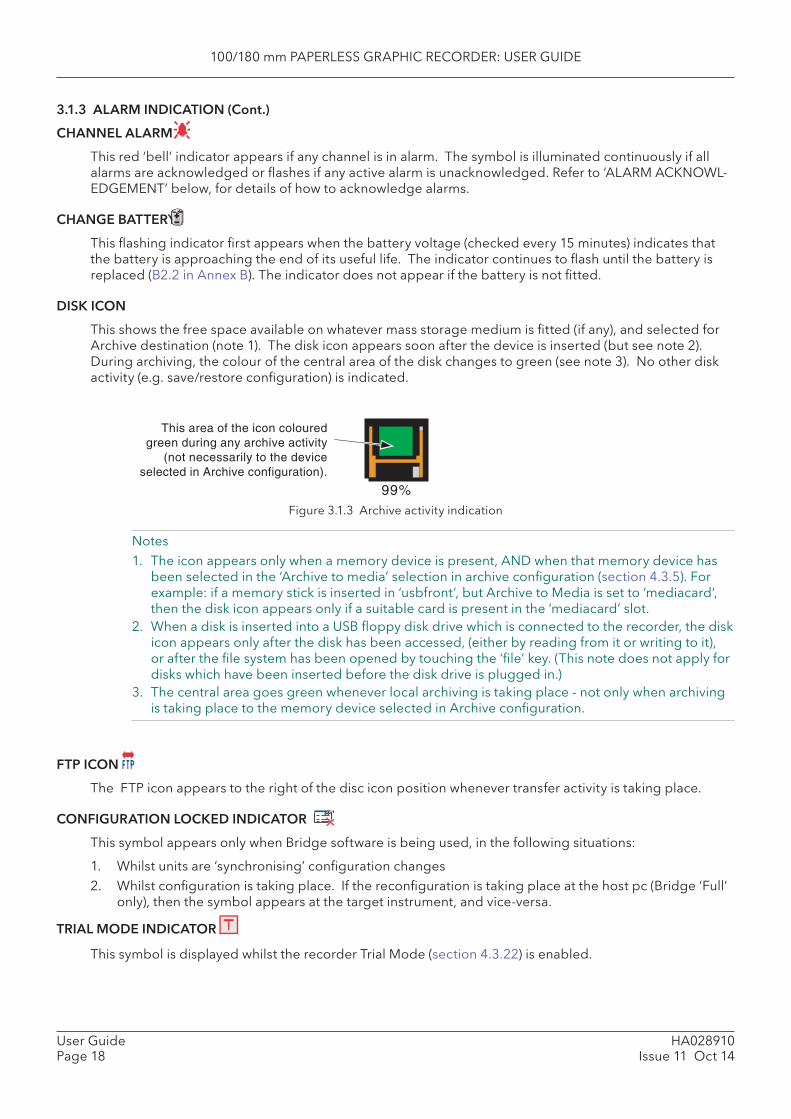
100/180 mm PAPERLESS GRAPHIC RECORDER: USER GUIDE
HA028910Issue 11 Oct 14
User GuidePage 18
3.1.3 ALARM INDICATION (Cont.)
CHANNEL ALARM
This red ‘bell’ indicator appears if any channel is in alarm. The symbol is illuminated continuously if all alarms are acknowledged or fl ashes if any active alarm is unacknowledged. Refer to ‘ALARM ACKNOWL-EDGEMENT’ below, for details of how to acknowledge alarms.
CHANGE BATTERY
This fl ashing indicator fi rst appears when the battery voltage (checked every 15 minutes) indicates that the battery is approaching the end of its useful life. The indicator continues to fl ash until the battery is replaced (B2.2 in Annex B). The indicator does not appear if the battery is not fi tted.
DISK ICON
This shows the free space available on whatever mass storage medium is fi tted (if any), and selected for Archive destination (note 1). The disk icon appears soon after the device is inserted (but see note 2). During archiving, the colour of the central area of the disk changes to green (see note 3). No other disk activity (e.g. save/restore confi guration) is indicated.
Figure 3.1.3 Archive activity indication
Notes1. The icon appears only when a memory device is present, AND when that memory device has
been selected in the ‘Archive to media’ selection in archive confi guration (section 4.3.5). For example: if a memory stick is inserted in ‘usbfront’, but Archive to Media is set to ‘mediacard’, then the disk icon appears only if a suitable card is present in the ‘mediacard’ slot.
2. When a disk is inserted into a USB fl oppy disk drive which is connected to the recorder, the disk icon appears only after the disk has been accessed, (either by reading from it or writing to it), or after the fi le system has been opened by touching the ‘fi le’ key. (This note does not apply for disks which have been inserted before the disk drive is plugged in.)
3. The central area goes green whenever local archiving is taking place - not only when archiving is taking place to the memory device selected in Archive confi guration.
FTP ICON
The FTP icon appears to the right of the disc icon position whenever transfer activity is taking place.
CONFIGURATION LOCKED INDICATOR
This symbol appears only when Bridge software is being used, in the following situations:
1. Whilst units are ‘synchronising’ confi guration changes2. Whilst confi guration is taking place. If the reconfi guration is taking place at the host pc (Bridge ‘Full’
only), then the symbol appears at the target instrument, and vice-versa.
TRIAL MODE INDICATOR
This symbol is displayed whilst the recorder Trial Mode (section 4.3.22) is enabled.
This area of the icon colouredgreen during any archive activity
(not necessarily to the deviceselected in Archive configuration).
99%
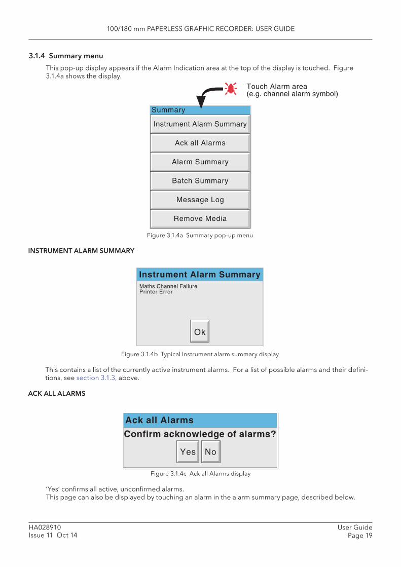
100/180 mm PAPERLESS GRAPHIC RECORDER: USER GUIDE
User GuidePage 19
HA028910Issue 11 Oct 14
3.1.4 Summary menu
This pop-up display appears if the Alarm Indication area at the top of the display is touched. Figure 3.1.4a shows the display.
Figure 3.1.4a Summary pop-up menu
INSTRUMENT ALARM SUMMARY
Figure 3.1.4b Typical Instrument alarm summary display
This contains a list of the currently active instrument alarms. For a list of possible alarms and their defi ni-tions, see section 3.1.3, above.
ACK ALL ALARMS
Figure 3.1.4c Ack all Alarms display
‘Yes’ confi rms all active, unconfi rmed alarms.This page can also be displayed by touching an alarm in the alarm summary page, described below.
Touch Alarm area(e.g. channel alarm symbol)
Ack all Alarms
Alarm Summary
Batch Summary
Message Log
Remove Media
Instrument Alarm Summary
Summary
Instrument Alarm Summary
Ok
Maths Channel FailurePrinter Error
Ack all Alarms
Yes No
Confirm acknowledge of alarms?
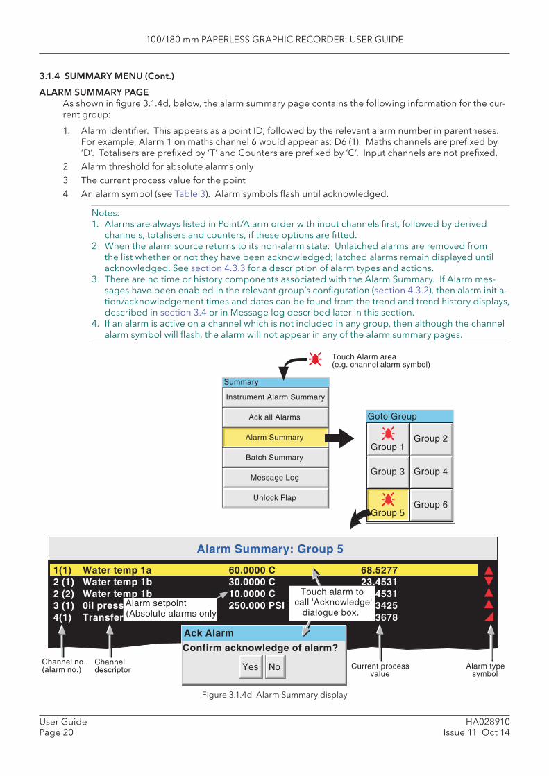
100/180 mm PAPERLESS GRAPHIC RECORDER: USER GUIDE
HA028910Issue 11 Oct 14
User GuidePage 20
3.1.4 SUMMARY MENU (Cont.)
ALARM SUMMARY PAGEAs shown in fi gure 3.1.4d, below, the alarm summary page contains the following information for the cur-rent group:
1. Alarm identifi er. This appears as a point ID, followed by the relevant alarm number in parentheses. For example, Alarm 1 on maths channel 6 would appear as: D6 (1). Maths channels are prefi xed by ‘D’. Totalisers are prefi xed by ‘T’ and Counters are prefi xed by ‘C’. Input channels are not prefi xed.
2 Alarm threshold for absolute alarms only3 The current process value for the point4 An alarm symbol (see Table 3). Alarm symbols fl ash until acknowledged.
Notes:1. Alarms are always listed in Point/Alarm order with input channels fi rst, followed by derived
channels, totalisers and counters, if these options are fi tted.2 When the alarm source returns to its non-alarm state: Unlatched alarms are removed from
the list whether or not they have been acknowledged; latched alarms remain displayed until acknowledged. See section 4.3.3 for a description of alarm types and actions.
3. There are no time or history components associated with the Alarm Summary. If Alarm mes-sages have been enabled in the relevant group’s confi guration (section 4.3.2), then alarm initia-tion/acknowledgement times and dates can be found from the trend and trend history displays, described in section 3.4 or in Message log described later in this section.
4. If an alarm is active on a channel which is not included in any group, then although the channel alarm symbol will fl ash, the alarm will not appear in any of the alarm summary pages.
Figure 3.1.4d Alarm Summary display
Ack all Alarms
Alarm Summary
Batch Summary
Message Log
Unlock Flap
Instrument Alarm Summary
Summary
Goto Group
Group 1Group 2
Group 5
Group 4
Group 6
Group 3
Touch Alarm area(e.g. channel alarm symbol)
Alarm Summary: Group 5
1(1) Water temp 1a 60.0000 C 68.52772 (1) Water temp 1b 30.0000 C 23.45312 (2) Water temp 1b 10.0000 C 23.45313 (1) 0il pressure 250.000 PSI 260.34254(1) Transfer 15.3678
Channel no.(alarm no.)
Channeldescriptor Alarm type
symbolCurrent process
value
Alarm setpoint (Absolute alarms only)
Ack Alarm
Yes No
Confirm acknowledge of alarm?
Touch alarm to call 'Acknowledge'
dialogue box.
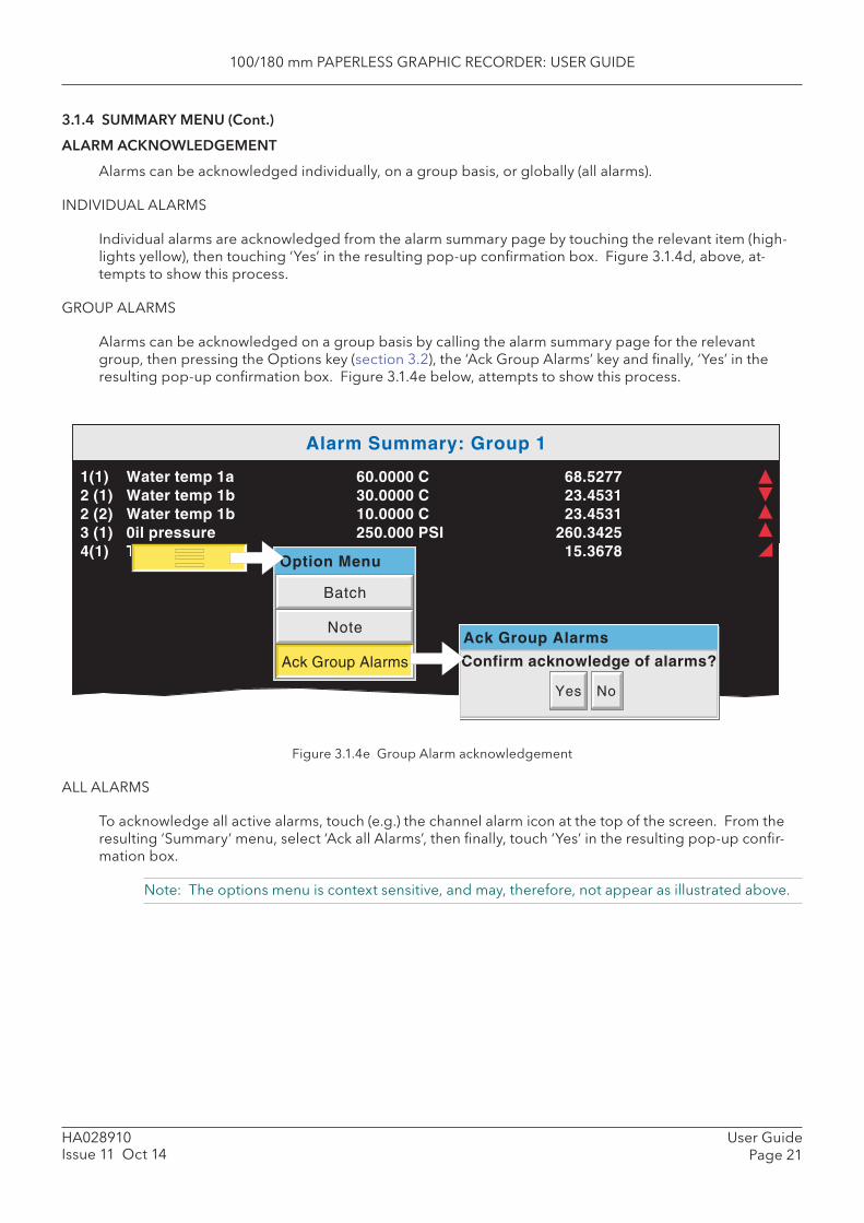
100/180 mm PAPERLESS GRAPHIC RECORDER: USER GUIDE
User GuidePage 21
HA028910Issue 11 Oct 14
3.1.4 SUMMARY MENU (Cont.)
ALARM ACKNOWLEDGEMENT
Alarms can be acknowledged individually, on a group basis, or globally (all alarms).
INDIVIDUAL ALARMS
Individual alarms are acknowledged from the alarm summary page by touching the relevant item (high-lights yellow), then touching ‘Yes’ in the resulting pop-up confi rmation box. Figure 3.1.4d, above, at-tempts to show this process.
GROUP ALARMS
Alarms can be acknowledged on a group basis by calling the alarm summary page for the relevant group, then pressing the Options key (section 3.2), the ‘Ack Group Alarms’ key and fi nally, ‘Yes’ in the resulting pop-up confi rmation box. Figure 3.1.4e below, attempts to show this process.
Figure 3.1.4e Group Alarm acknowledgement
ALL ALARMS
To acknowledge all active alarms, touch (e.g.) the channel alarm icon at the top of the screen. From the resulting ‘Summary’ menu, select ‘Ack all Alarms’, then fi nally, touch ‘Yes’ in the resulting pop-up confi r-mation box.
Note: The options menu is context sensitive, and may, therefore, not appear as illustrated above.
Alarm Summary: Group 1
1(1) Water temp 1a 60.0000 C 68.52772 (1) Water temp 1b 30.0000 C 23.45312 (2) Water temp 1b 10.0000 C 23.45313 (1) 0il pressure 250.000 PSI 260.34254(1) Transfer 15.3678
Yes No
Confirm acknowledge of alarms?
Batch
Note
Ack Group Alarms
Option Menu
Ack Group Alarms
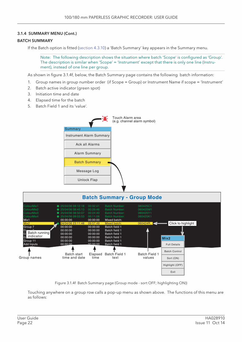
100/180 mm PAPERLESS GRAPHIC RECORDER: USER GUIDE
HA028910Issue 11 Oct 14
User GuidePage 22
3.1.4 SUMMARY MENU (Cont.)
BATCH SUMMARY
If the Batch option is fi tted (section 4.3.10) a ‘Batch Summary’ key appears in the Summary menu.
Note: The following description shows the situation where batch ‘Scope’ is confi gured as ‘Group’. The description is similar when ‘Scope’ = ‘Instrument’ except that there is only one line (Instru-ment), instead of one line per group.
As shown in fi gure 3.1.4f, below, the Batch Summary page contains the following batch information:
1. Group names in group number order (if Scope = Group) or Instrument Name if scope = ‘Instrument’2. Batch active indicator (green spot)3. Initiation time and date4. Elapsed time for the batch5. Batch Field 1 and its ‘value’.
Figure 3.1.4f Batch Summary page (Group mode - sort OFF; highlighting ON))
Touching anywhere on a group row calls a pop-up menu as shown above. The functions of this menu are as follows:
Ack all Alarms
Alarm Summary
Batch Summary
Message Log
Unlock Flap
Instrument Alarm Summary
Summary
Touch Alarm area(e.g. channel alarm symbol)
Batch Summary - Group Mode
Group namesBatch start
time and dateElapsed
timeBatch Field 1
textBatch Field 1
values
ColourMix1 25/04/06 09:12:18 00:02:41 Batch Number: 060425C1ColourMix2 25/04/06 08:45:13 00:29:46 Batch Number: 060425M1ColourMix3 25/04/06 08:50:07 00:24:40 Batch Number: 060425Y1ColourMix4 25/04/06 09:03:53 00:11:06 Batch Number: 060425K1Mix1 00:00:00 00:00:00 Mixed batch:Mix2 24/04/06 23:11:48 09:57:49 Mixed batch: 060424R..Group 7 00:00:00 00:00:00 Batch field 1Group 8 00:00:00 00:00:00 Batch field 1Group 9 00:00:00 00:00:00 Batch field 1Group 10 00:00:00 00:00:00 Batch field 1Group 11 00:00:00 00:00:00 Batch field 1Add Inputs 00:00:00 00:00:00 Batch field 1
Batch runningindicator
Click to highlight
Full Details
Batch Control
Sort (ON)
Highlight (OFF)
Exit
Mix2

100/180 mm PAPERLESS GRAPHIC RECORDER: USER GUIDE
User GuidePage 23
HA028910Issue 11 Oct 14
3.1.4 SUMMARY MENU (Cont.)
BATCH SUMMARY (Cont.)
FULL DETAILS
Touching this key calls the Batch Details page showing the group name, batch status and batch fi eld details.
BATCH CONTROL
This calls a page similar to the Full Details page, but including a ‘NEW’ key to allow the operator to start a new batch. If the batch is confi gured as ‘Start/Stop’ a ‘Stop’ key is also included allowing the user to stop the batch.
SORT
If Sort is Off (default), the groups appear in Group number order with Group 1 at the top and group 12 at the bottom. The key legend is ‘Sort (ON)’.
If Sort is On, those groups with batches running appear (in group number order) at the top of the list, fol-lowed by any remaining groups (also in group number order). The key legend is ‘Sort (OFF)’.
HIGHLIGHT
If Highlight is Off (default), then all groups’ text appears in white. The key legend is ‘Highlight (ON)’.
If Highlight is On then the text associated with groups which have batches running appears in green. Remaining groups’ text is in white. The key legend is ‘Highlight (OFF)’.
EXIT
Closes the pop-up menu. (It closes itself after approximately 50 seconds.)
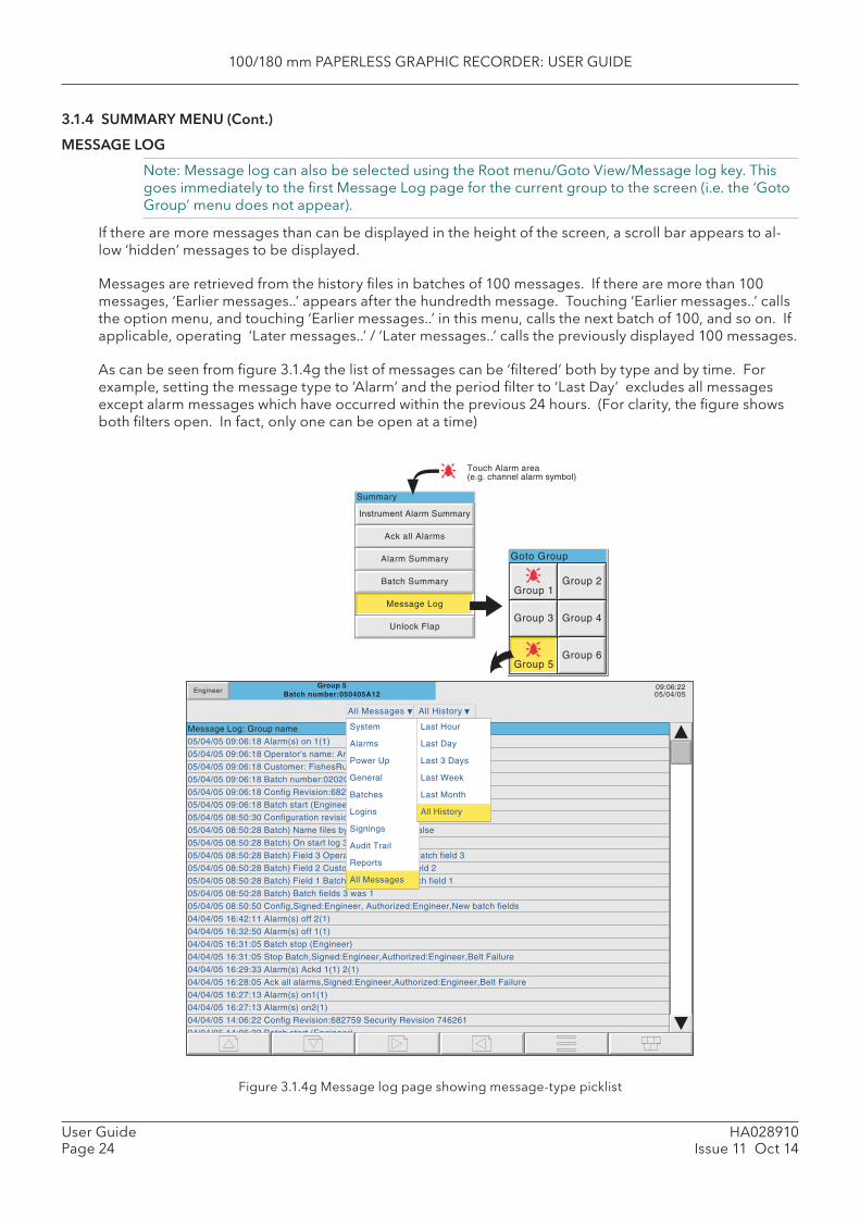
100/180 mm PAPERLESS GRAPHIC RECORDER: USER GUIDE
HA028910Issue 11 Oct 14
User GuidePage 24
3.1.4 SUMMARY MENU (Cont.)
MESSAGE LOG
Note: Message log can also be selected using the Root menu/Goto View/Message log key. This goes immediately to the fi rst Message Log page for the current group to the screen (i.e. the ‘Goto Group’ menu does not appear).
If there are more messages than can be displayed in the height of the screen, a scroll bar appears to al-low ‘hidden’ messages to be displayed.
Messages are retrieved from the history fi les in batches of 100 messages. If there are more than 100 messages, ‘Earlier messages..’ appears after the hundredth message. Touching ‘Earlier messages..’ calls the option menu, and touching ‘Earlier messages..’ in this menu, calls the next batch of 100, and so on. If applicable, operating ‘Later messages..’ / ‘Later messages..’ calls the previously displayed 100 messages.
As can be seen from fi gure 3.1.4g the list of messages can be ‘fi ltered’ both by type and by time. For example, setting the message type to ‘Alarm’ and the period fi lter to ‘Last Day’ excludes all messages except alarm messages which have occurred within the previous 24 hours. (For clarity, the fi gure shows both fi lters open. In fact, only one can be open at a time)
Figure 3.1.4g Message log page showing message-type picklist
Ack all Alarms
Alarm Summary
Batch Summary
Message Log
Unlock Flap
Instrument Alarm Summary
Summary
Group 5Batch number:050405A12
09:06:2205/04/05Engineer
Message Log: Group name
All Messages All History
05/04/05 09:06:18 Alarm(s) on 1(1)
05/04/05 09:06:18 Operator's name: Andrew
05/04/05 09:06:18 Customer: FishesRus
05/04/05 09:06:18 Batch number:020205A12
05/04/05 09:06:18 Config Revision:682759 Security Revision 746261
05/04/05 09:06:18 Batch start (Engineer)
05/04/05 08:50:30 Configuration revision 682,759 was 682,758
05/04/05 08:50:28 Batch) Name files by batch true was false
05/04/05 08:50:28 Batch) On start log 3 was 1
05/04/05 08:50:28 Batch) Field 3 Operator's name: was Batch field 3
05/04/05 08:50:28 Batch) Field 2 Customer: was Batch field 2
05/04/05 08:50:28 Batch) Field 1 Batch number: was Batch field 1
05/04/05 08:50:28 Batch) Batch fields 3 was 1
05/04/05 08:50:50 Config,Signed:Engineer, Authorized:Engineer,New batch fields
04/04/05 16:42:11 Alarm(s) off 2(1)
04/04/05 16:32:50 Alarm(s) off 1(1)
04/04/05 16:31:05 Batch stop (Engineer)
04/04/05 16:31:05 Stop Batch,Signed:Engineer,Authorized:Engineer,Belt Failure
04/04/05 16:29:33 Alarm(s) Ackd 1(1) 2(1)
04/04/05 16:28:05 Ack all alarms,Signed:Engineer,Authorized:Engineer,Belt Failure
04/04/05 16:27:13 Alarm(s) on1(1)
04/04/05 16:27:13 Alarm(s) on2(1)
04/04/05 14:06:22 Config Revision:682759 Security Revision 746261
04/04/05 14:06:22 Batch start (Engineer)
System
Alarms
Power Up
General
Batches
Logins
Signings
Audit Trail
Reports
All Messages
Last Hour
Last Day
Last 3 Days
Last Week
Last Month
All History
Goto Group
Group 1Group 2
Group 5
Group 4
Group 6
Group 3
Touch Alarm area(e.g. channel alarm symbol)

100/180 mm PAPERLESS GRAPHIC RECORDER: USER GUIDE
User GuidePage 25
HA028910Issue 11 Oct 14
3.1.4 SUMMARY MENU (Cont.)
MESSAGE LOG (Cont.)
MESSAGE TYPE FILTER
All Messages All messages are displayed System Only System messages and instrument alarms are listed Alarms Only alarm on/off and acknowledgement messages appear. Power Up Displays power up messages only including Confi g Revision and Security revision are
included. See ‘About’ (section 4.6.11) for more details. General Displays e-mails, messages sent via Modbus, operator notes/custom messages etc. if they
do not have to be ‘signed’ (Auditor option 21CFR11 only - see section 4.4 for more details). If the notes etc. are signed, they appear in the ‘Signings’ message type list.
Batches Displays only batch messages (including Confi g and Security Revisions if either Auditor option is enabled).
Logins Lists only changes in login. Signings This list contains only notes, messages etc. that have been signed (and authorized). This
category is used only when ‘Require Signing’ (and ‘Require Authorization’) is (are) enabled in the Security/Management menu- see section 4.4 for more details.
Audit trail This list contains Confi guration change messages only. This category is used only when ‘Audit Trail’ is enabled - see section 4.4 for more details.
Reports For each report, this contains all the Report’s fi elds (set up in ‘Reports’ confi guration) on separate lines. Line Feed fi elds are ignored (i.e. they do not appear).
PERIOD FILTER
This picklist allows the user to select one of the following to defi ne the period of time that the message list is to encompass:
All History, Last Month (28 days), Last Week, Last 3 Days, Last Day or Last Hour.
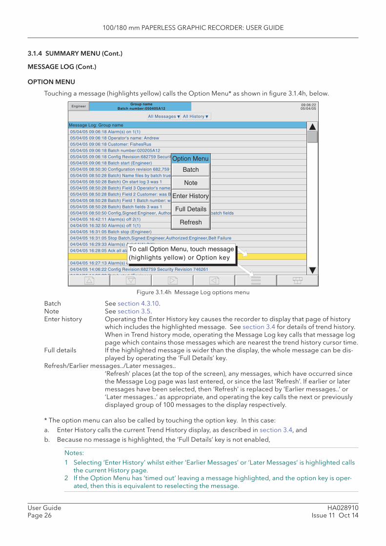
100/180 mm PAPERLESS GRAPHIC RECORDER: USER GUIDE
HA028910Issue 11 Oct 14
User GuidePage 26
3.1.4 SUMMARY MENU (Cont.)
MESSAGE LOG (Cont.)
OPTION MENU
Touching a message (highlights yellow) calls the Option Menu* as shown in fi gure 3.1.4h, below.
Figure 3.1.4h Message Log options menu
Batch See section 4.3.10. Note See section 3.5. Enter history Operating the Enter History key causes the recorder to display that page of history
which includes the highlighted message. See section 3.4 for details of trend history. When in Trend history mode, operating the Message Log key calls that message log page which contains those messages which are nearest the trend history cursor time.
Full details If the highlighted message is wider than the display, the whole message can be dis-played by operating the ‘Full Details’ key.
Refresh/ Earlier messages../ Later messages.. ‘Refresh’ places (at the top of the screen), any messages, which have occurred since
the Message Log page was last entered, or since the last ‘Refresh’. If earlier or later messages have been selected, then ‘Refresh’ is replaced by ‘Earlier messages..’ or ‘Later messages..’ as appropriate, and operating the key calls the next or previously displayed group of 100 messages to the display respectively.
* The option menu can also be called by touching the option key. In this case:a. Enter History calls the current Trend History display, as described in section 3.4, and b. Because no message is highlighted, the ‘Full Details’ key is not enabled,
Notes:1 Selecting ‘Enter History’ whilst either ‘Earlier Messages’ or ‘Later Messages’ is highlighted calls
the current History page.2 If the Option Menu has ‘timed out’ leaving a message highlighted, and the option key is oper-
ated, then this is equivalent to reselecting the message.
05/04/05 09:06:18 Alarm(s) on 1(1)
05/04/05 09:06:18 Operator's name: Andrew
05/04/05 09:06:18 Customer: FishesRus
05/04/05 09:06:18 Batch number:020205A12
05/04/05 09:06:18 Config Revision:682759 Security Revision 746261
05/04/05 09:06:18 Batch start (Engineer)
05/04/05 08:50:30 Configuration revision 682,759 was 682,758
05/04/05 08:50:28 Batch) Name files by batch true was false
05/04/05 08:50:28 Batch) On start log 3 was 1
05/04/05 08:50:28 Batch) Field 3 Operator's name: was Batch field 3
05/04/05 08:50:28 Batch) Field 2 Customer: was Batch field 2
05/04/05 08:50:28 Batch) Field 1 Batch number: was Batch field 1
05/04/05 08:50:28 Batch) Batch fields 3 was 1
05/04/05 08:50:50 Config,Signed:Engineer, Authorized:Engineer,New batch fields
04/04/05 16:42:11 Alarm(s) off 2(1)
04/04/05 16:32:50 Alarm(s) off 1(1)
04/04/05 16:31:05 Batch stop (Engineer)
04/04/05 16:31:05 Stop Batch,Signed:Engineer,Authorized:Engineer,Belt Failure
04/04/05 16:29:33 Alarm(s) Ackd 1(1) 2(1)
04/04/05 16:28:05 Ack all alarms,Signed:Engineer,Authorized:Engineer,Belt Failure
04/04/05 16:27:13 Alarm(s) on1(1)
04/04/05 16:27:13 Alarm(s) on2(1)
04/04/05 14:06:22 Config Revision:682759 Security Revision 746261
04/04/05 14:06:22 Batch start (Engineer)
Engineer
Message Log: Group name
All Messages All History
To call Option Menu, touch message(highlights yellow) or Option key
Group nameBatch number:050405A12
09:06:2205/04/05
Option Menu
Batch
Note
Enter History
Full Details
Refresh
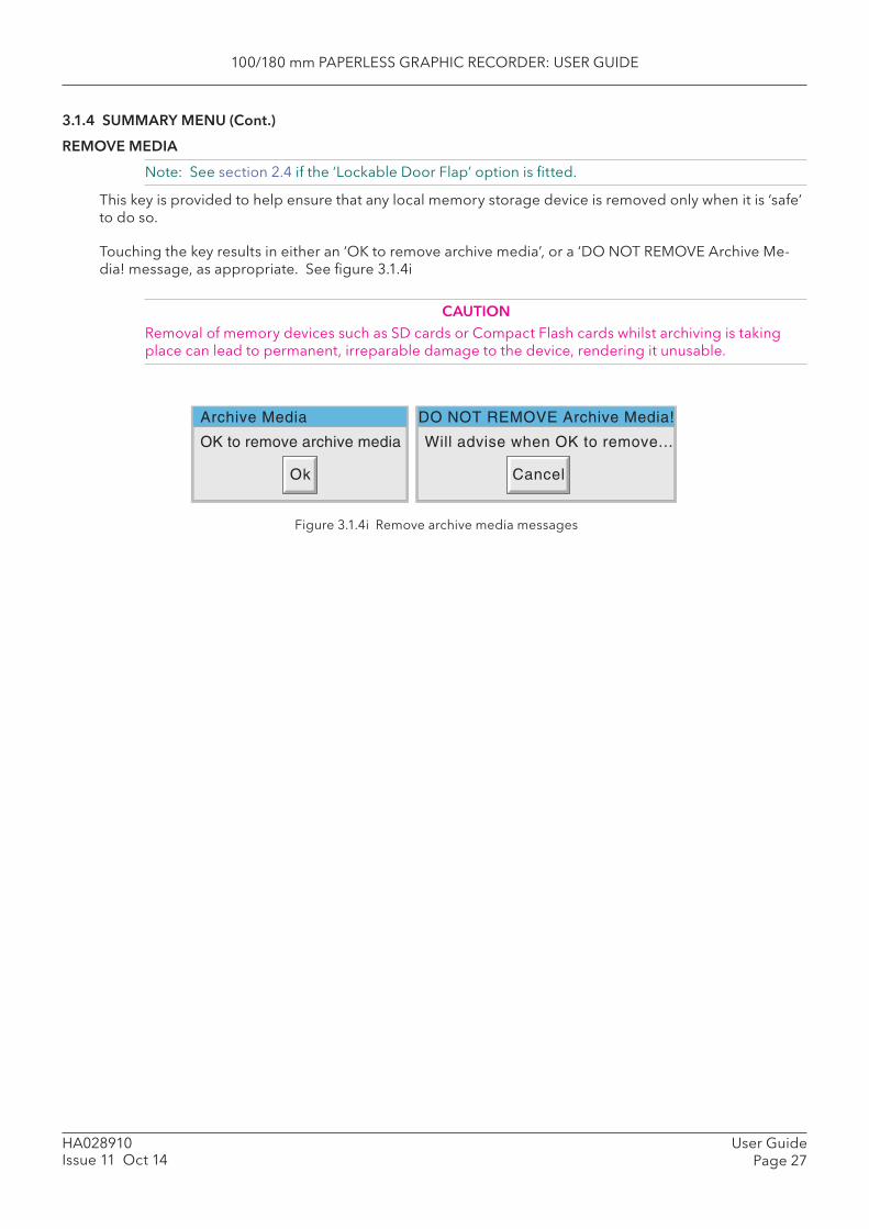
100/180 mm PAPERLESS GRAPHIC RECORDER: USER GUIDE
User GuidePage 27
HA028910Issue 11 Oct 14
3.1.4 SUMMARY MENU (Cont.)
REMOVE MEDIA
Note: See section 2.4 if the ‘Lockable Door Flap’ option is fi tted.
This key is provided to help ensure that any local memory storage device is removed only when it is ‘safe’ to do so.
Touching the key results in either an ‘OK to remove archive media’, or a ‘DO NOT REMOVE Archive Me-dia! message, as appropriate. See fi gure 3.1.4i
CAUTIONRemoval of memory devices such as SD cards or Compact Flash cards whilst archiving is taking place can lead to permanent, irreparable damage to the device, rendering it unusable.
Figure 3.1.4i Remove archive media messages
OK to remove archive media
Ok
Will advise when OK to remove...
Cancel
Archive Media DO NOT REMOVE Archive Media!
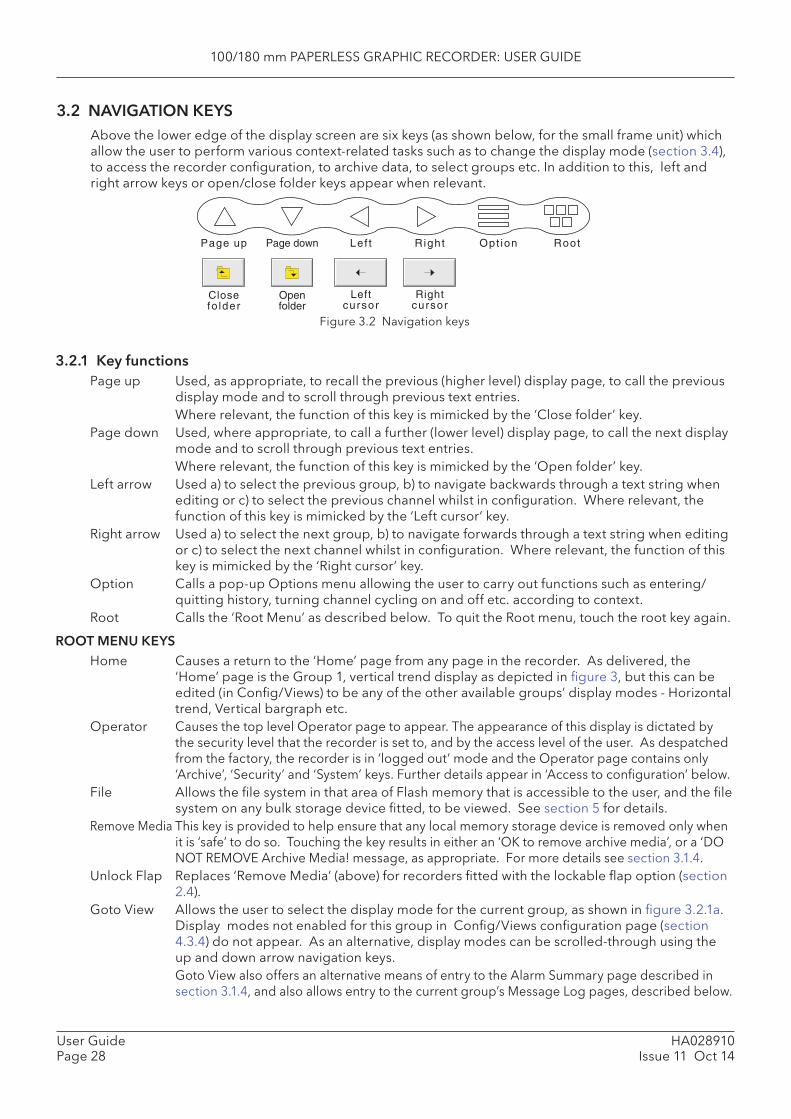
100/180 mm PAPERLESS GRAPHIC RECORDER: USER GUIDE
HA028910Issue 11 Oct 14
User GuidePage 28
3.2 NAVIGATION KEYS Above the lower edge of the display screen are six keys (as shown below, for the small frame unit) which allow the user to perform various context-related tasks such as to change the display mode (section 3.4), to access the recorder confi guration, to archive data, to select groups etc. In addition to this, left and right arrow keys or open/close folder keys appear when relevant.
Page up Page down Lef t Right Opt ion Root
Closefo lder
Openfolder
Leftcursor
Rightcursor
Figure 3.2 Navigation keys
3.2.1 Key functions Page up Used, as appropriate, to recall the previous (higher level) display page, to call the previous
display mode and to scroll through previous text entries. Where relevant, the function of this key is mimicked by the ‘Close folder’ key.Page down Used, where appropriate, to call a further (lower level) display page, to call the next display
mode and to scroll through previous text entries. Where relevant, the function of this key is mimicked by the ‘Open folder’ key. Left arrow Used a) to select the previous group, b) to navigate backwards through a text string when
editing or c) to select the previous channel whilst in confi guration. Where relevant, the function of this key is mimicked by the ‘ Left cursor’ key.
Right arrow Used a) to select the next group, b) to navigate forwards through a text string when editing or c) to select the next channel whilst in confi guration. Where relevant, the function of this key is mimicked by the ‘Right cursor’ key.
Option Calls a pop-up Options menu allowing the user to carry out functions such as entering/quitting history, turning channel cycling on and off etc. according to context.
Root Calls the ‘Root Menu’ as described below. To quit the Root menu, touch the root key again.
ROOT MENU KEYS Home Causes a return to the ‘Home’ page from any page in the recorder. As delivered, the
‘Home’ page is the Group 1, vertical trend display as depicted in fi gure 3, but this can be edited (in Confi g/Views) to be any of the other available groups’ display modes - Horizontal trend, Vertical bargraph etc.
Operator Causes the top level Operator page to appear. The appearance of this display is dictated by the security level that the recorder is set to, and by the access level of the user. As despatched from the factory, the recorder is in ‘logged out’ mode and the Operator page contains only ‘Archive’, ‘Security’ and ‘System’ keys. Further details appear in ‘Access to confi guration’ below.
File Allows the fi le system in that area of Flash memory that is accessible to the user, and the fi le system on any bulk storage device fi tted, to be viewed. See section 5 for details.
Remove Media This key is provided to help ensure that any local memory storage device is removed only when it is ‘safe’ to do so. Touching the key results in either an ‘OK to remove archive media’, or a ‘DO NOT REMOVE Archive Media! message, as appropriate. For more details see section 3.1.4.
Unlock Flap Replaces ‘Remove Media’ (above) for recorders fi tted with the lockable fl ap option (section 2.4).
Goto View Allows the user to select the display mode for the current group, as shown in fi gure 3.2.1a. Display modes not enabled for this group in Confi g/Views confi guration page (section 4.3.4) do not appear. As an alternative, display modes can be scrolled-through using the up and down arrow navigation keys.
Goto View also offers an alternative means of entry to the Alarm Summary page described in section 3.1.4, and also allows entry to the current group’s Message Log pages, described below.
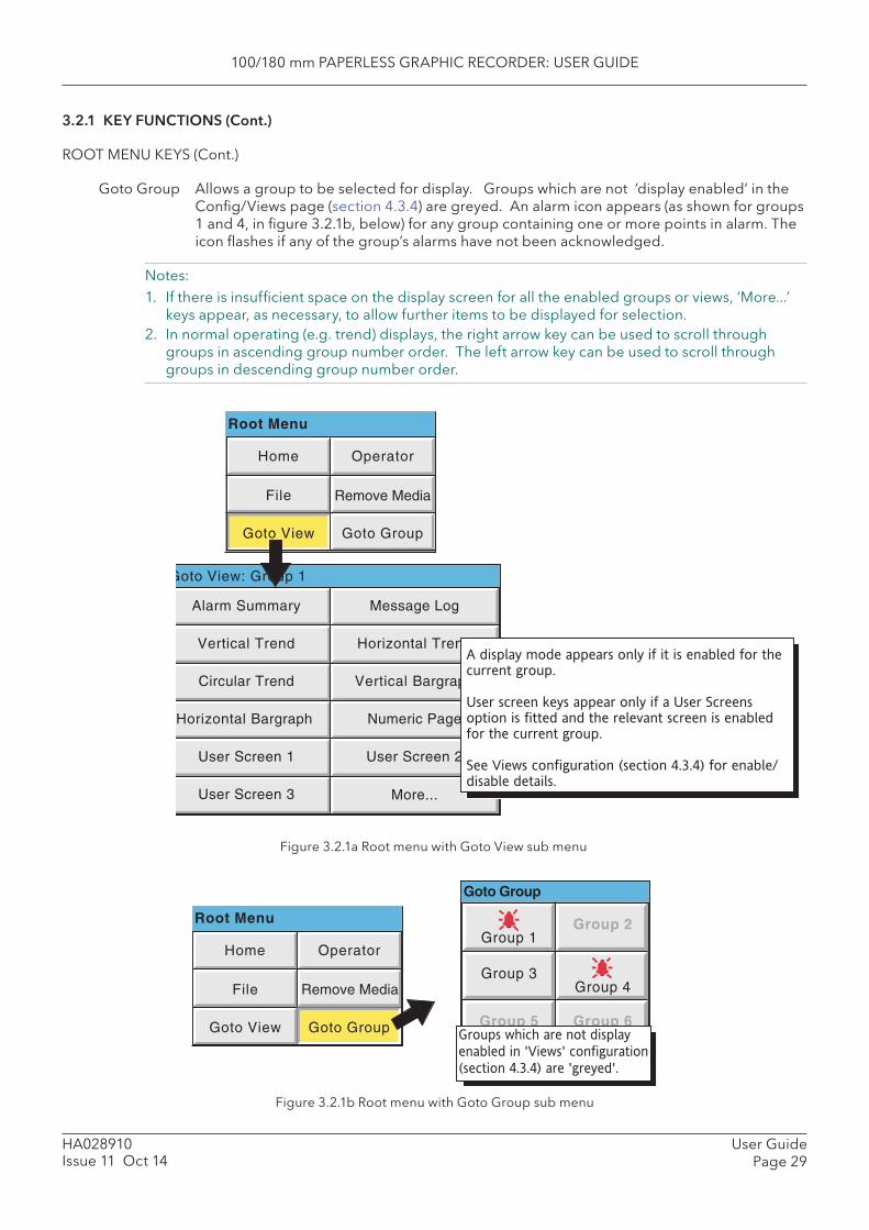
100/180 mm PAPERLESS GRAPHIC RECORDER: USER GUIDE
User GuidePage 29
HA028910Issue 11 Oct 14
3.2.1 KEY FUNCTIONS (Cont.)
ROOT MENU KEYS (Cont.)
Goto Group Allows a group to be selected for display. Groups which are not ‘display enabled’ in the Confi g/Views page (section 4.3.4) are greyed. An alarm icon appears (as shown for groups 1 and 4, in fi gure 3.2.1b, below) for any group containing one or more points in alarm. The icon fl ashes if any of the group’s alarms have not been acknowledged.
Notes:1. If there is insuffi cient space on the display screen for all the enabled groups or views, ‘More...’
keys appear, as necessary, to allow further items to be displayed for selection.2. In normal operating (e.g. trend) displays, the right arrow key can be used to scroll through
groups in ascending group number order. The left arrow key can be used to scroll through groups in descending group number order.
Figure 3.2.1a Root menu with Goto View sub menu
Figure 3.2.1b Root menu with Goto Group sub menu
Home Operator
File
Goto View Goto Group
Message Log
Horizontal Trend
Vertical Bargraph
Alarm Summary
Vertical Trend
Circular Trend
Numeric Page
User Screen 2
Horizontal Bargraph
User Screen 1
User Screen 3 More...
A display mode appears only if it is enabled for the
current group.
User screen keys appear only if a User Screens
option is fitted and the relevant screen is enabled
for the current group.
See Views configuration (section 4.3.4) for enable/
disable details.
Root Menu
Goto View: Group 1
Remove Media
Home Operator
File
Goto View Goto Group
Group 1Group 2
Group 3Group 4
Group 5 Group 6Groups which are not display
enabled in 'Views' configuration
(section 4.3.4) are 'greyed'.
Root Menu
Goto Group
Remove Media

100/180 mm PAPERLESS GRAPHIC RECORDER: USER GUIDE
HA028910Issue 11 Oct 14
User GuidePage 30
3.2.1 KEY FUNCTIONS (Cont.)
ALARM SUMMARY
The Root menu/Goto View/Alarm summary key calls the Alarm summary page for the current group to the screen. Alternatively, Alarm summary can be selected from the Alarm, Message and Media menu, but in this case, the user must select an alarm summary group from a pop-up (Goto Group) menu. See section 3.1.4 for more details of the alarm summary page.
MESSAGE LOG
The Root menu/Goto View/Message log key calls the Message Log page for the current group to the screen. Alternatively, Message Log can be selected from the Alarm, Message and Media menu, but in this case, the user must select a ‘Group’ for the Message Log display from a pop-up (Goto Group) menu.
See section 3.1.4 for full details of the message log.
100/180 mm PAPERLESS GRAPHIC RECORDER: USER GUIDE
User GuidePage 31
HA028910Issue 11 Oct 14
3.3 FIRST SWITCH-ONWhen power is applied the recorder initialises, and once this process is complete, the home page is displayed. It is unlikely that this will contain any useful information because the input channels will not, as yet, have been confi gured to suit the type of input signals being applied to them, as described in section 4.
Notes:1 There is no on/off switch associated with the recorder.2 Date, time and the message ‘ Power Up’ are printed on the chart each time power is applied to
the recorder, followed by a similar message giving ‘Confi g Revision’ and ‘Security Revision’.3 A red line is drawn across the width of the chart at power up
The recorder has four security levels as follows:
Logged out Initially, no access to recorder confi guration is possible. Only Archive, Login/security and the System ‘About’ functions can be accessed - via the root menu. Limited or full access can be permitted from ‘Engineer’ level.
Operator* No access to recorder confi guration is possible until access permissions have been set up. Section 4.4.1 describes how limited or full access can be permitted by an operator with ‘Engineer’ level access.
Engineer* Accessed initially, by entering ‘ 100’ as the password (section 3.3.1, below). Full access to all recorder functions is available. Section 4.4.1 describes how the Engineer level password can be edited and an Operator password can be entered if required. The section also de-scribes how access permission to some or all of the recorder functions can be granted, or not, to individual user names and default security levels (except ‘Service’).
Service Full access to all recorder functions and to areas of recorder memory for diagnostic pur-poses. For use only by Service Engineers.
*Note: For units with the Auditor 21CFR11 Option enabled, the default Engineer and Operator passwords are both ‘100’.
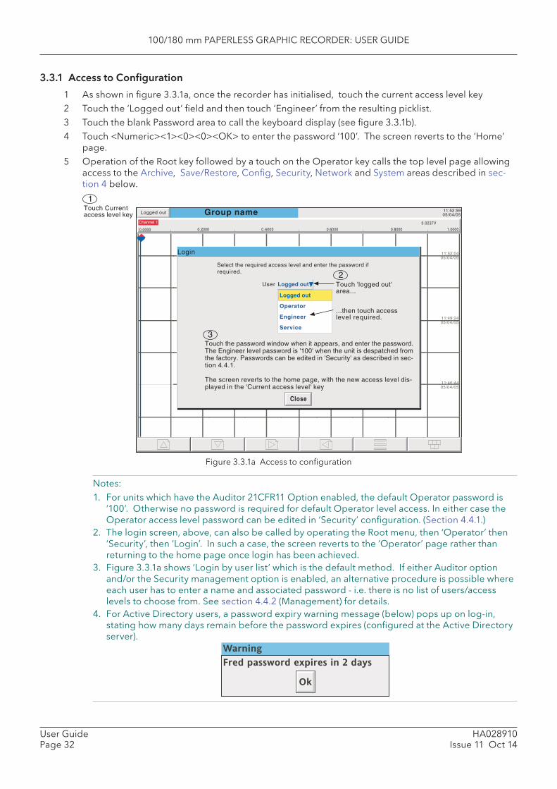
100/180 mm PAPERLESS GRAPHIC RECORDER: USER GUIDE
HA028910Issue 11 Oct 14
User GuidePage 32
3.3.1 Access to Confi guration
1 As shown in fi gure 3.3.1a, once the recorder has initialised, touch the current access level key2 Touch the ‘Logged out’ fi eld and then touch ‘Engineer’ from the resulting picklist.3 Touch the blank Password area to call the keyboard display (see fi gure 3.3.1b).4 Touch <Numeric><1><0><0><OK> to enter the password ‘100’. The screen reverts to the ‘Home’
page.5 Operation of the Root key followed by a touch on the Operator key calls the top level page allowing
access to the Archive, Save/Restore, Confi g, Security, Network and System areas described in sec-tion 4 below.
Figure 3.3.1a Access to confi guration
Notes: 1. For units which have the Auditor 21CFR11 Option enabled, the default Operator password is
‘100’. Otherwise no password is required for default Operator level access. In either case the Operator access level password can be edited in ‘Security’ confi guration. (Section 4.4.1.)
2. The login screen, above, can also be called by operating the Root menu, then ‘Operator’ then ‘Security’, then ‘Login’. In such a case, the screen reverts to the ‘Operator’ page rather than returning to the home page once login has been achieved.
3. Figure 3.3.1a shows ‘Login by user list’ which is the default method. If either Auditor option and/or the Security management option is enabled, an alternative procedure is possible where each user has to enter a name and associated password - i.e. there is no list of users/access levels to choose from. See section 4.4.2 (Management) for details.
4. For Active Directory users, a password expiry warning message (below) pops up on log-in, stating how many days remain before the password expires (confi gured at the Active Directory server).
Touch Currentaccess level key Group name 11:52:59
05/04/05
11:52:0405/04/05
11:49:2405/04/05
11:46:4405/04/05
Logged out
Login
Select the required access level and enter the password ifrequired.
Close
User Logged out
Operator
Engineer
Service
Logged out
Touch 'logged out'area...
...then touch accesslevel required.
Touch the password window when it appears, and enter the password.The Engineer level password is '100' when the unit is despatched fromthe factory. Passwords can be edited in 'Security' as described in sec-tion 4.4.1.
The screen reverts to the home page, with the new access level dis-played in the 'Current access level' key
0.0000 1.0000
Channel 1 0.0237V
0.2000 0.4000 0.6000 0.8000
1
2
3
Warning
Fred password expires in 2 days
Ok
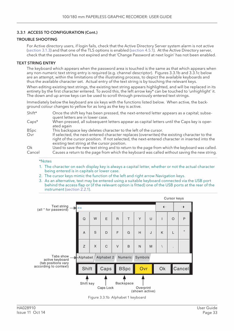
100/180 mm PAPERLESS GRAPHIC RECORDER: USER GUIDE
User GuidePage 33
HA028910Issue 11 Oct 14
3.3.1 ACCESS TO CONFIGURATION (Cont.)
TROUBLE SHOOTING
For Active directory users, if login fails, check that the Active Directory Server system alarm is not active (section 3.1.3) and that one of the TLS options is enabled (section 4.5.1). At the Active Directory server, check that the password has not expired and that ‘Change Password at next login’ has not been enabled.
TEXT STRING ENTRY The keyboard which appears when the password area is touched is the same as that which appears when any non-numeric text string entry is required (e.g. channel descriptor). Figures 3.3.1b and 3.3.1c below are an attempt, within the limitations of the illustrating process, to depict the available keyboards and thus the available character set. Actual entry of the text string is by touching the relevant keys. When editing existing text strings, the existing text string appears highlighted, and will be replaced in its entirety by the fi rst character entered. To avoid this, the left arrow key* can be touched to ‘unhighlight’ it. The down and up arrow keys can be used to scroll through previously entered text strings.
Immediately below the keyboard are six keys with the functions listed below. When active, the back-ground colour changes to yellow for as long as the key is active.
Shift* Once the shift key has been pressed, the next-entered letter appears as a capital; subse-quent letters are in lower case.
Caps* When pressed, all subsequent letters appear as capital letters until the Caps key is oper-ated again
BSpc This backspace key deletes character to the left of the cursor. Ovr If selected, the next-entered character replaces (overwrites) the existing character to the
right of the cursor position. If not selected, the next-entered character in inserted into the existing text string at the cursor position.
Ok Used to save the new text string and to return to the page from which the keyboard was called.Cancel Causes a return to the page from which the keyboard was called without saving the new string.
*Notes1. The character on each display key is always a capital letter, whether or not the actual character
being entered is in capitals or lower case.2. The cursor keys mimic the function of the left and right arrow Navigation keys.3. As an alternative, text may be entered using a suitable keyboard connected via the USB port
behind the access fl ap or (if the relevant option is fi tted) one of the USB ports at the rear of the instrument (section 2.2.1).
Figure 3.3.1b Alphabet 1 keyboard
SymbolsNumericAlphabet 2
**
Alphabet
Shift Caps BSpc Ovr Ok Cancel
Shift key Backspace
Text string(all * for password)
Q W E R T Y U I O P
A S D F G H J K L ˚
Z X C V B N M \ .
Cursor keys
Tabs showactive keyboard
(tab positions varyaccording to context)
Caps Lock Overprint(shown active)
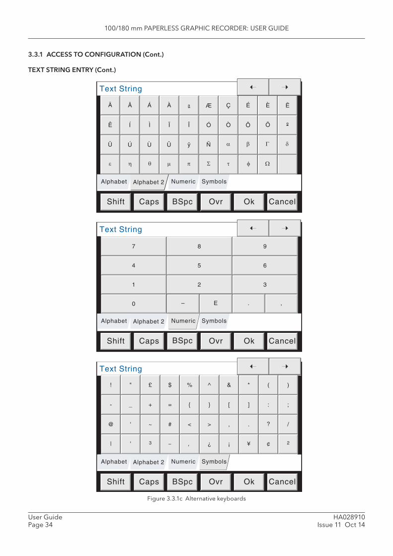
100/180 mm PAPERLESS GRAPHIC RECORDER: USER GUIDE
HA028910Issue 11 Oct 14
User GuidePage 34
3.3.1 ACCESS TO CONFIGURATION (Cont.)
TEXT STRING ENTRY (Cont.)
Figure 3.3.1c Alternative keyboards
SymbolsNumeric
Text String
Alphabet
Shift Caps BSpc Ok Cancel
Alphabet 2
Ovr
SymbolsNumeric
Text String
Alphabet
Shift Caps BSpc Ok Cancel
Alphabet 2
Ovr
Numeric
Text String
Alphabet
Shift Caps BSpc Ok Cancel
Alphabet 2
Ovr
Symbols
Ä Å Á À Æ Ç É Èa Ë
Ê Í Ì Ï Ó Ò ÔÎ Ö º
Ü Ú Ù Û Ñÿ β Γ δα
τ φ ΩΣθ μ πηε
! " £ $ ^ & * ( )
- _ + = } [ ] : ;
@ ' ~ # > , . ? /
| ' 3 – ¿ ¡ ¥ ¢
{
<
‚
%
2
7 8 9
4 5 6
1 2 3
0 . ,– E
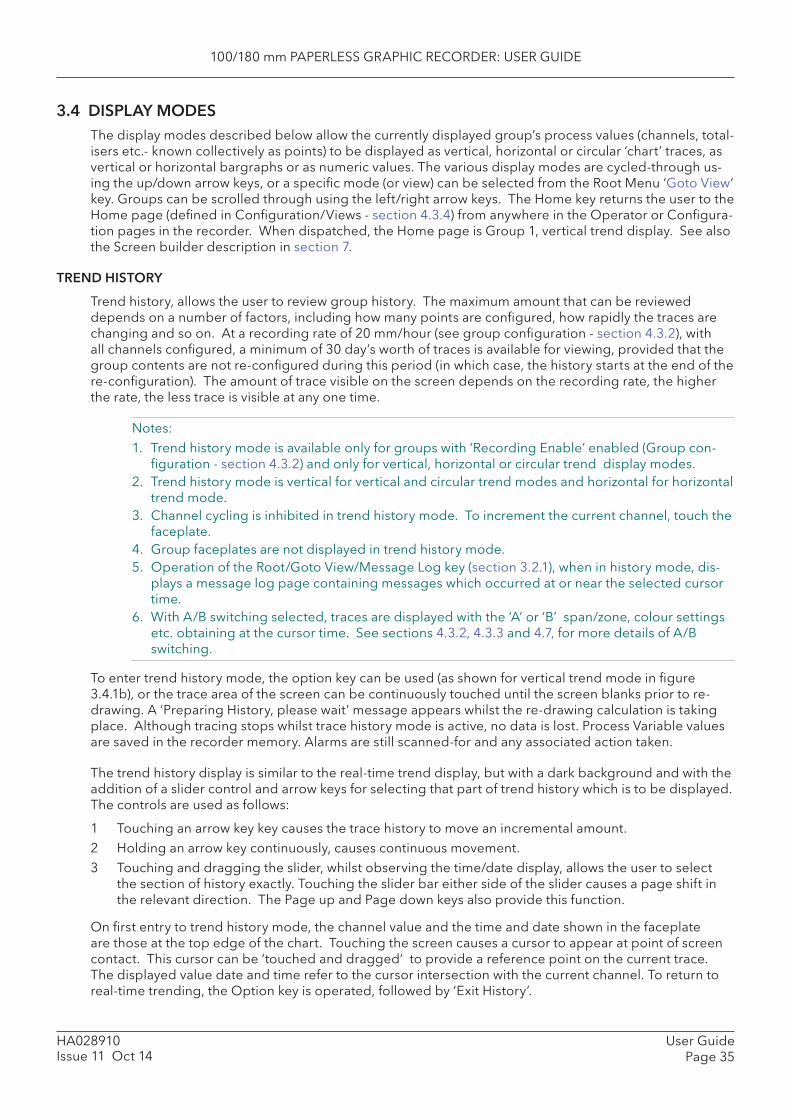
100/180 mm PAPERLESS GRAPHIC RECORDER: USER GUIDE
User GuidePage 35
HA028910Issue 11 Oct 14
3.4 DISPLAY MODESThe display modes described below allow the currently displayed group’s process values (channels, total-isers etc.- known collectively as points) to be displayed as vertical, horizontal or circular ‘chart’ traces, as vertical or horizontal bargraphs or as numeric values. The various display modes are cycled-through us-ing the up/down arrow keys, or a specifi c mode (or view) can be selected from the Root Menu ‘Goto View’ key. Groups can be scrolled through using the left/right arrow keys. The Home key returns the user to the Home page (defi ned in Confi guration/Views - section 4.3.4) from anywhere in the Operator or Confi gura-tion pages in the recorder. When dispatched, the Home page is Group 1, vertical trend display. See also the Screen builder description in section 7.
TREND HISTORY
Trend history, allows the user to review group history. The maximum amount that can be reviewed depends on a number of factors, including how many points are confi gured, how rapidly the traces are changing and so on. At a recording rate of 20 mm/hour (see group confi guration - section 4.3.2), with all channels confi gured, a minimum of 30 day’s worth of traces is available for viewing, provided that the group contents are not re-confi gured during this period (in which case, the history starts at the end of the re-confi guration). The amount of trace visible on the screen depends on the recording rate, the higher the rate, the less trace is visible at any one time.
Notes: 1. Trend history mode is available only for groups with ‘Recording Enable’ enabled (Group con-
fi guration - section 4.3.2) and only for vertical, horizontal or circular trend display modes. 2. Trend history mode is vertical for vertical and circular trend modes and horizontal for horizontal
trend mode.3. Channel cycling is inhibited in trend history mode. To increment the current channel, touch the
faceplate.4. Group faceplates are not displayed in trend history mode.5. Operation of the Root/Goto View/Message Log key (section 3.2.1), when in history mode, dis-
plays a message log page containing messages which occurred at or near the selected cursor time.
6. With A/B switching selected, traces are displayed with the ‘A’ or ‘B’ span/zone, colour settings etc. obtaining at the cursor time. See sections 4.3.2, 4.3.3 and 4.7, for more details of A/B switching.
To enter trend history mode, the option key can be used (as shown for vertical trend mode in fi gure 3.4.1b), or the trace area of the screen can be continuously touched until the screen blanks prior to re-drawing. A ‘Preparing History, please wait’ message appears whilst the re-drawing calculation is taking place. Although tracing stops whilst trace history mode is active, no data is lost. Process Variable values are saved in the recorder memory. Alarms are still scanned-for and any associated action taken.
The trend history display is similar to the real-time trend display, but with a dark background and with the addition of a slider control and arrow keys for selecting that part of trend history which is to be displayed. The controls are used as follows:
1 Touching an arrow key key causes the trace history to move an incremental amount. 2 Holding an arrow key continuously, causes continuous movement. 3 Touching and dragging the slider, whilst observing the time/date display, allows the user to select
the section of history exactly. Touching the slider bar either side of the slider causes a page shift in the relevant direction. The Page up and Page down keys also provide this function.
On fi rst entry to trend history mode, the channel value and the time and date shown in the faceplate are those at the top edge of the chart. Touching the screen causes a cursor to appear at point of screen contact. This cursor can be ‘touched and dragged’ to provide a reference point on the current trace. The displayed value date and time refer to the cursor intersection with the current channel. To return to real-time trending, the Option key is operated, followed by ‘Exit History’.

100/180 mm PAPERLESS GRAPHIC RECORDER: USER GUIDE
HA028910Issue 11 Oct 14
User GuidePage 36
3.4 DISPLAY MODES (Cont.)
TIME CHANGE RECORDS
For vertical and horizontal trend modes a line is drawn across the width of the chart whenever a time discontinuity in the record occurs. These lines disappear if a confi guration change which causes group history to be lost, is made (such as adding a new channel to a group).
Red line A red line is drawn on the trend history chart at power up.Blue line A blue line indicates that recording has been disabled/enabled in Group Confi guration
(section 4.3.2), or by a recording job (section 4.7.10). Blue lines are not drawn when the Simulation Option is active.
Green line A green line appears if there has been a time change as a result of a clock job (section 4.7.6), an SNTP synchronisation or by the operator physically changing the recorder time.
Note: Changes from standard time to daylight saving time and back again are not ‘green lined’ in this way
3.4.1 Vertical Trend display
This display (fi gure 3.4.1b) shows each point in the display group as though it were being traced on a white chart. It is possible to change the appearance of the chart in the System key ‘Customise’ area of confi guration (section 4.6.10). It is recommended that some thought be given to ensuring good contrast between trace colours and background colour.
One of the channels is said to be the ‘current’ or ‘scale’ channel. This channel is identifi ed by its diamond shaped pen icon and by its descriptor, digital value and scale being displayed on a ‘faceplate’ across the full width of the screen, above the chart. If a channel is included in the display group but its status is ‘not good’ for some reason, then its pen icon is hollow.
Faceplates for all the group channels can be displayed, by using the Faceplates On/Off key in the option menu. If selected On, faceplates (showing colour, descriptor, digital value and units) for all the group’s channels appear either above the current channel’s faceplate or, if there are too many to fi t across the screen, at the right hand edge of the screen. When necessary, a slider bar appears to allow further (hid-den) faceplates to be viewed.
Each channel in the display group becomes the ‘current’ channel, in turn, for approximately 10 seconds – i.e. the channels are cycled-through, starting with the lowest numbered channel. Once the fi nal chan-nel in the group has been displayed for 10 seconds, the lowest numbered channel is returned to and the sequence repeats. This scrolling process can be enabled or disabled using the Channel Cycling On (Off) key in the Option menu.
To select a particular channel to be the current channel, the relevant pen icon can be touched. To cycle through the channels manually, the faceplate area is touched repeatedly until the required channel is reached.
The Horizontal Trend display can be called using the down arrow key. Alternatively, any one of the ena-bled display modes (section 4.3.4) can be selected using the Root Menu, ‘Goto View’ key.
Figure 3.4.1a Option Menu (Typical)
OptionKey
Option Menu
Enter History
Channel Cycling Off
Faceplates On/Off
Batch
Note
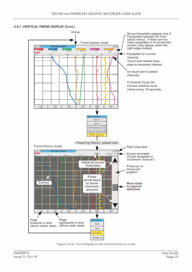
100/180 mm PAPERLESS GRAPHIC RECORDER: USER GUIDE
User GuidePage 37
HA028910Issue 11 Oct 14
3.4.1 VERTICAL TREND DISPLAY (Cont.)
Figure 3.4.1b Trend display mode and trend history mode
O p t i o n M e n u
E n t e r H i s t o r y
Channel Cycling Off
Facep la tes On /Of f
B a t c h
N o t e
Option Menu
Batch
Note
Exit History
Message Log
Channel 1
400.00
686.84 ˚C
640.00
G r o u p n a m e 11:53:090 4 / 0 5 / 0 4
11:52:040 5 / 0 4 / 0 5
11:49:240 5 / 0 4 / 0 5
14:46:440 5 / 0 4 / 0 5
05/04/05 18:28:22 Alarms(s) on 3(1)
05/04/05 18:33:04 Alarms(s) off 3(1)
Cursor
Real time/dateTrend History mode
Press bar tomove onepageful
Pageforwards in time(show newer data)
Pagebackwards in time(Show older data)
E n g i n e e r
G r o u p n a m e 11:52:590 5 / 0 4 / 0 5
11:52:040 5 / 0 4 / 0 5
11:49:240 5 / 0 4 / 0 5
11:46:440 5 / 0 4 / 0 5
05/04/05 11:47:51 Alarms(s) on 3(1)
05/04/05 11:51:33 Alarms(s) off 3(1)
Home
Trend display modeE n g i n e e r
Preparing History, please wait
0 4 / 0 5 / 0 4 1 1 : 4 9 : 5 4 Cursor time/date(Touch faceplate toincrement channel.)
800.00720.005 6 0 . 0 04 8 0 . 0 0
Faceplate for currentchannel.Touch and release face-plate to increment channel
(or touch pen to selectchannel).
If Channel Cycle On:Current channel incre-ments every 10 seconds.
Pressarrow keys
to moveminimumamount
Value at cursortime/date
Channel 1
400.00 800.00
700.87
720.00640.00480.00 560.00
Channel 1700.87˚C
Channel 2487.39˚C
Channel 3235.68˚C
Channel 4378.99˚C
Channel 50.49V
Channel 60.85V
Group faceplates (appear only ifFaceplates selected On fromoption menu). If there are toomany faceplates to fit across thescreen, they appear down theright edge instead.
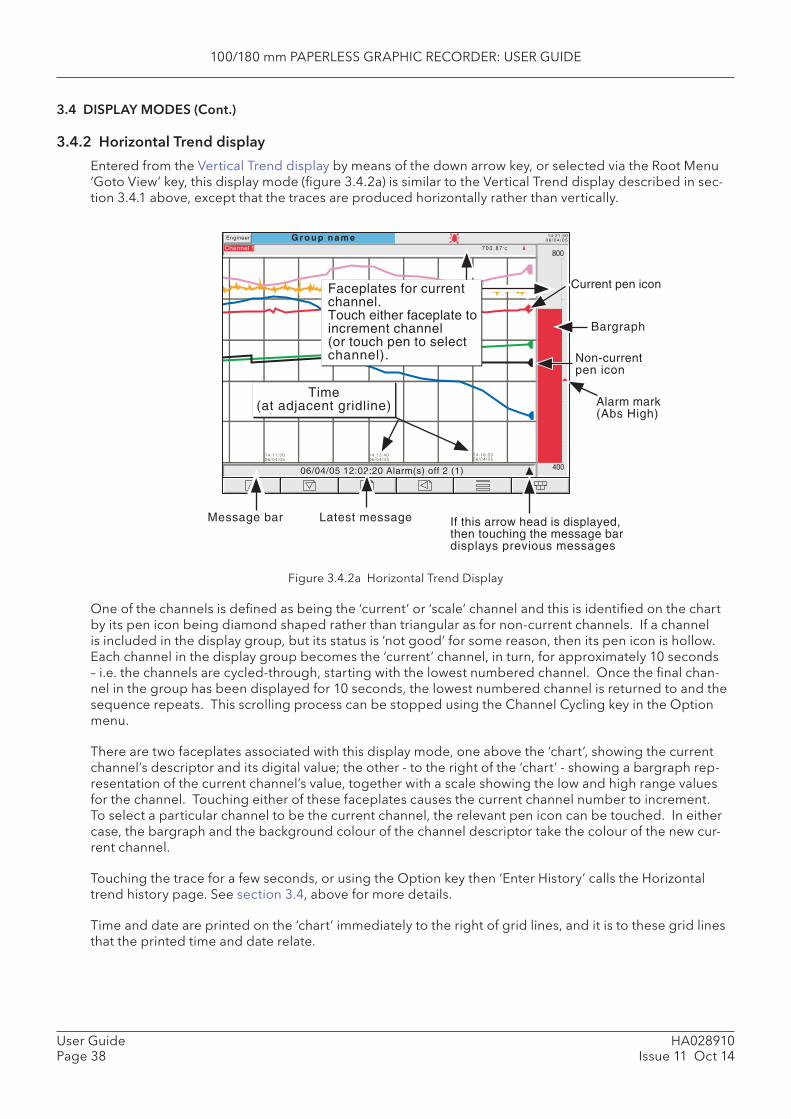
100/180 mm PAPERLESS GRAPHIC RECORDER: USER GUIDE
HA028910Issue 11 Oct 14
User GuidePage 38
3.4 DISPLAY MODES (Cont.)
3.4.2 Horizontal Trend display
Entered from the Vertical Trend display by means of the down arrow key, or selected via the Root Menu ‘Goto View’ key, this display mode (fi gure 3.4.2a) is similar to the Vertical Trend display described in sec-tion 3.4.1 above, except that the traces are produced horizontally rather than vertically.
Figure 3.4.2a Horizontal Trend Display
One of the channels is defi ned as being the ‘current’ or ‘scale’ channel and this is identifi ed on the chart by its pen icon being diamond shaped rather than triangular as for non-current channels. If a channel is included in the display group, but its status is ‘not good’ for some reason, then its pen icon is hollow. Each channel in the display group becomes the ‘current’ channel, in turn, for approximately 10 seconds – i.e. the channels are cycled-through, starting with the lowest numbered channel. Once the fi nal chan-nel in the group has been displayed for 10 seconds, the lowest numbered channel is returned to and the sequence repeats. This scrolling process can be stopped using the Channel Cycling key in the Option menu.
There are two faceplates associated with this display mode, one above the ‘chart’, showing the current channel’s descriptor and its digital value; the other - to the right of the ‘chart’ - showing a bargraph rep-resentation of the current channel’s value, together with a scale showing the low and high range values for the channel. Touching either of these faceplates causes the current channel number to increment. To select a particular channel to be the current channel, the relevant pen icon can be touched. In either case, the bargraph and the background colour of the channel descriptor take the colour of the new cur-rent channel.
Touching the trace for a few seconds, or using the Option key then ‘Enter History’ calls the Horizontal trend history page. See section 3.4, above for more details.
Time and date are printed on the ‘chart’ immediately to the right of grid lines, and it is to these grid lines that the printed time and date relate.
G r o u p n a m e 14:21:300 6 / 0 4 / 0 5Engineer
Channel 1 7 0 0 . 8 7˚C
400
800
14:16:2006/04/05
14:13:4006/04/05
14:11:0006/04/05
Bargraph
Current pen icon
Time(at adjacent gridline)
Faceplates for currentchannel.Touch either faceplate toincrement channel(or touch pen to selectchannel).
06/04/05 12:02:20 Alarm(s) off 2 (1)
If this arrow head is displayed,then touching the message bardisplays previous messages
Latest messageMessage bar
Non-currentpen icon
Alarm mark(Abs High)
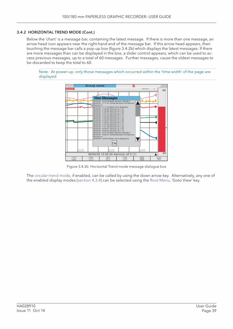
100/180 mm PAPERLESS GRAPHIC RECORDER: USER GUIDE
User GuidePage 39
HA028910Issue 11 Oct 14
3.4.2 HORIZONTAL TREND MODE (Cont.)
Below the ‘chart’ is a message bar, containing the latest message. If there is more than one message, an arrow head icon appears near the right-hand end of the message bar. If this arrow head appears, then touching the message bar calls a pop-up box (fi gure 3.4.2b) which displays the latest messages. If there are more messages than can be displayed in the box, a slider control appears, which can be used to ac-cess previous messages, up to a total of 60 messages. Further messages, cause the oldest messages to be discarded to keep the total to 60.
Note: At power-up, only those messages which occurred within the ‘time width’ of the page are displayed
Figure 3.4.2b Horizontal Trend mode message dialogue box
The circular trend mode, if enabled, can be called by using the down arrow key. Alternatively, any one of the enabled display modes (section 4.3.4) can be selected using the Root Menu, ‘Goto View’ key.
G r o u p n a m e 14:21:300 6 / 0 4 / 0 5
E n g i n e e r
Channel 1 7 0 0 . 8 7˚C
400
800
14:16:2006/04/05
14:13:4006/04/05
14:11:0006/04/05
06/04/05 12:02:20 Alarm(s) off 2 (1)
View Messages06/04/05 12:02:20 Batch Number 050406-306/04/05 11:11:41 Config Revision:218 SecurityRevision:306/04/05 11:11:34 Batch start (Engineer)06/04/05 11:09:34 Alarm(s) on 1 (1)06/04/05 11:09:26 Alarm(s) off 1 (2)06/04/05 11:07:41 Alarm(s) on 1 (2)06/04/05 11:07:34 Alarm(s) off 1 (1)06/04/05 11:05:34 Alarm(s) on 1 (1)06/04/05 11:05:26 Alarm(s) off 1 (2)06/04/05 11:03:41 Alarm(s) on 1 (2)06/04/05 11:03:34 Alarm(s) off 1 (1)06/04/05 11:01:34 Alarm(s) on 1 (1)06/04/05 11:01:26 Alarm(s) off 1 (2)06/04/05 10:59:41 Alarm(s) on 1 (2)06/04/05 10:59:34 Alarm(s) off 1 (1)06/04/05 10:57:34 Batch Number 050406-206/04/05 10:55:41 Config Revision:218 SecurityRevision:306/04/05 10:55:34 Batch start (Engineer))
Ok

100/180 mm PAPERLESS GRAPHIC RECORDER: USER GUIDE
HA028910Issue 11 Oct 14
User GuidePage 40
3.4.3 Circular Trend
This allows up to 12 points to be traced as though on a circular chart. More than 12 points can be in-cluded in the group, but only the fi rst 12 traces and their associated faceplates are included in the real-time display. Entering Trend History mode (by using the Options button or by continuously touching the screen for a few seconds), allows all the points to be reviewed, but only in vertical trend history mode, described in section 3.4 above.
For large frame recorders, two alternative views called ‘Full Screen’ and ‘Normal View’ are available and are toggled between by means of a push-button key near the top left corner of the screen. In each case, faceplates can be displayed, or not, as required, using the Option key ‘Faceplates On/Off’ selection. The diameter of the chart is independent of faceplate on/off selection. When quitting History, Normal view is always returned to. Small frame recorders use only ‘full screen’ view, (except when viewed via Bridge software when the small frame recorder behaves in the same way as the large frame recorder).
Notes Alarm icons (section 3) do not appear on circular trend scales.
TREND MODES
The way in which traces are laid down on the chart depends on the action to be taken when the chart is ‘full’, as set up in group confi guration - section 4.3.2. The user can select ‘Rotate’ or ‘New Chart’.
ROTATE
In the following description, the word ‘segment’ is used interchangeably with ‘Major chart division’. The number of Major chart divisions is a function of the selected chart speed, as described in Group Confi gu-ration (section 4.3.2).
With ‘Rotate’ selected, the traces start one major chart division anti-clockwise from the top of the chart and trace clockwise until they reach the top of the chart (‘12 o’clock’). At this point, the chart, complete with time stamps and traces, rotates one major chart division anticlockwise, and the tracing process con-tinues. When the chart is ‘full’, the oldest segment-full of tracing is removed, leaving an empty segment to be traced-on when the chart rotates.
Figures 3.4.3b and 3.4.3c, below show Circular trending in ‘Rotate’ mode.
NEW CHART
With ‘New Chart’ selected, tracing starts at top of the chart (12 o’clock) and continue to trace clockwise round the chart, back up to the vertical. When the chart is full, it is cleared, new timestamps are dis-played, and tracing restarts from the top of the chart.
The start time of the tracing can be set as a part (‘Start at’) of group confi guration, the choices available depending on the time per revolution setting. The start time is placed at top centre of the chart, and ‘backfi lled’, clockwise, round to the current time.
Figure 3.4.3a, below, shows New Chart mode.
Note: The use of ‘12 o’clock’ above is intended to be illustrative and only to explain angles in terms of a normal analogue clock face. It does not mean that this position must actually be noon or midnight in real time.
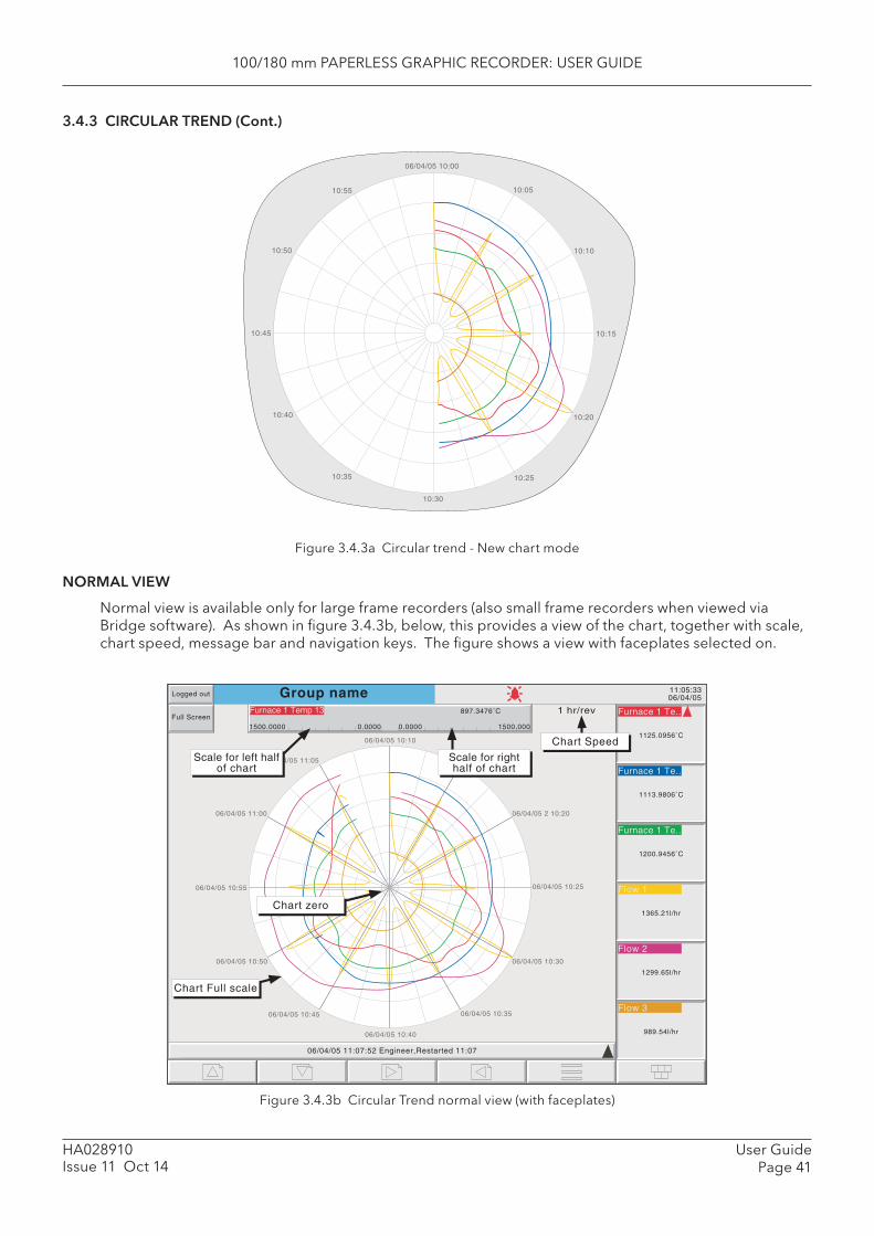
100/180 mm PAPERLESS GRAPHIC RECORDER: USER GUIDE
User GuidePage 41
HA028910Issue 11 Oct 14
3.4.3 CIRCULAR TREND (Cont.)
Figure 3.4.3a Circular trend - New chart mode
NORMAL VIEW
Normal view is available only for large frame recorders (also small frame recorders when viewed via Bridge software). As shown in fi gure 3.4.3b, below, this provides a view of the chart, together with scale, chart speed, message bar and navigation keys. The fi gure shows a view with faceplates selected on.
Figure 3.4.3b Circular Trend normal view (with faceplates)
06/04/05 10:00
10:05
10:10
10:15
10:20
10:25
10:30
10:35
10:40
10:45
10:50
10:55
Group name 11:05:3306/04/05Logged out
Full ScreenFurnace 1 Temp 13
1500.0000 0.0000 0.0000 1500.000
06/04/05 10:10
14/08/02 10:15
06/04/05 2 10:20
06/04/05 10:25
06/04/05 10:30
06/04/05 10:35
06/04/05 10:40
06/04/05 10:45
06/04/05 10:50
06/04/05 10:55
06/04/05 11:00
06/04/05 11:05
06/04/05 11:07:52 Engineer,Restarted 11:07
Furnace 1 Te..
1125.0956˚C
Furnace 1 Te..
1113.9806˚C
Furnace 1 Te..
1200.9456˚C
Flow 1
1365.21l/hr
Flow 2
1299.65l/hr
Flow 3
989.54l/hr
Chart zero
Chart Full scale
Scale for left halfof chart
1 hr/rev
Chart Speed
Scale for righthalf of chart
897.3476˚C
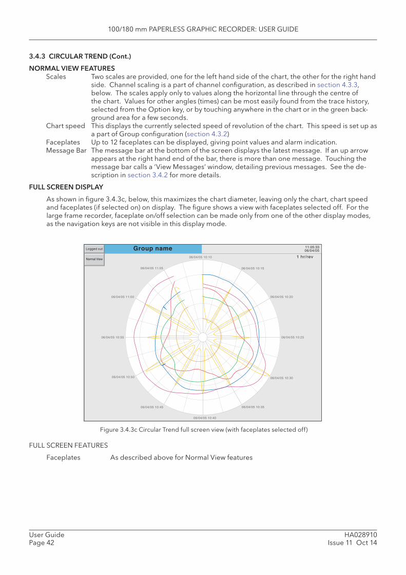
100/180 mm PAPERLESS GRAPHIC RECORDER: USER GUIDE
HA028910Issue 11 Oct 14
User GuidePage 42
3.4.3 CIRCULAR TREND (Cont.)
NORMAL VIEW FEATURES Scales Two scales are provided, one for the left hand side of the chart, the other for the right hand
side. Channel scaling is a part of channel confi guration, as described in section 4.3.3, below. The scales apply only to values along the horizontal line through the centre of the chart. Values for other angles (times) can be most easily found from the trace history, selected from the Option key, or by touching anywhere in the chart or in the green back-ground area for a few seconds.
Chart speed This displays the currently selected speed of revolution of the chart. This speed is set up as a part of Group confi guration (section 4.3.2)
Faceplates Up to 12 faceplates can be displayed, giving point values and alarm indication. Message Bar The message bar at the bottom of the screen displays the latest message. If an up arrow
appears at the right hand end of the bar, there is more than one message. Touching the message bar calls a ‘View Messages’ window, detailing previous messages. See the de-scription in section 3.4.2 for more details.
FULL SCREEN DISPLAY
As shown in fi gure 3.4.3c, below, this maximizes the chart diameter, leaving only the chart, chart speed and faceplates (if selected on) on display. The fi gure shows a view with faceplates selected off. For the large frame recorder, faceplate on/off selection can be made only from one of the other display modes, as the navigation keys are not visible in this display mode.
Figure 3.4.3c Circular Trend full screen view (with faceplates selected off)
FULL SCREEN FEATURES
Faceplates As described above for Normal View features
Group name 11:05:3306/04/05Logged out
Normal View06/04/05 10:10
06/04/05 10:15
06/04/05 10:20
06/04/05 10:25
06/04/05 10:30
06/04/05 10:35
06/04/05 10:40
06/04/05 10:45
06/04/05 10:50
06/04/05 10:55
06/04/05 11:00
06/04/05 11:05
1 hr/rev

100/180 mm PAPERLESS GRAPHIC RECORDER: USER GUIDE
User GuidePage 43
HA028910Issue 11 Oct 14
3.4.3 CIRCULAR TREND (Cont.)
TIMESTAMPS
Time and/or date are displayed at every major chart division. The following rules apply:
1. For chart durations of a week or more, only the date is displayed2. For chart durations of less than a week, both time and date appear, with the following exception:
In ‘New Chart’ mode (unless the chart ‘bridges’ midnight), the date appears only at top centre of the chart. All other chart divisions are identifi ed by time only.
OTHER NOTES
1. Adaptive recording results in two traces per trend, as in other trend display modes.2. For successful circular trend display, ‘Circular Settings’ must be enabled for the relevant group (sec-
tion 4.3.2), and ‘Circular Trend’ must be enabled for the group, in Views confi guration (section 4.3.4). If Circular Trend is enabled, but Circular Settings is disabled, then, although the circular chart will appear, it is unlikely that it will contain any trends.
3. The circular chart speed is unaffected by A/B switching of Trend Speed/Interval (section 4.3.2).4. Circular trends backfi ll only to the previous power up.

100/180 mm PAPERLESS GRAPHIC RECORDER: USER GUIDE
HA028910Issue 11 Oct 14
User GuidePage 44
3.4 DISPLAY MODES (Cont.)
3.4.4 Vertical bargraph
Entered from Circular Trend mode by means of the down arrow key, or selected from the Root Menu ‘Goto View’ key, this display mode shows the Process Variable (PV) values as vertical bars with faceplates containing digital values and alarm data. There are two versions, one with faceplates above the bars (1 to 6 channels - fi gure 3.4.4a); the other (with faceplates at the right hand edge of the display - fi gure 3.4.4b) is used where there are more than six channels.
Note: The description above refers to the 180 mm version of the recorder. For the 100 mm ver-sion, the faceplates appear above the bars for one or two points, but to the right of the bars for three or more points.
Operation of the option key calls the Option menu display for this display page, allowing faceplates to be selected on or off. This feature is available for vertical trend, circular trend and vertical bargraph displays only.
To call the horizontal bargraph display mode, use the down arrow key. Alternatively, any one of the ena-bled display modes (section 4.3.4) can be selected using the Root Menu, ‘Goto View’ key.
Trend history mode is not available from this display mode.
FACEPLATES ABOVE THE BARS
See fi gure 3.4.4a.
As the number of channels in the display group increases, the bars and their faceplates get narrower,
FACEPLATES AT RIGHT-HAND EDGE
See fi gure 3.4.4b.
As the number of PVs increases, the bars get narrower. As the bars get narrower, so the scale values become truncated as shown in fi gure 3.4.4b. The bars have a set minimum width, and if the total number of points in the group cannot be displayed within the width of the screen, a horizontal scroll bar appears, allowing ‘hidden’ bars to be viewed. Similarly, the faceplates reduce in height to a minimum readable height. If there are more point faceplates than can be accommodated within the height of the screen, a vertical scroll bar appears, allowing hidden faceplates to be displayed as required.
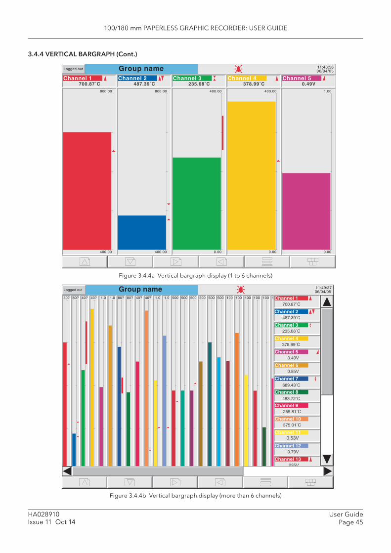
100/180 mm PAPERLESS GRAPHIC RECORDER: USER GUIDE
User GuidePage 45
HA028910Issue 11 Oct 14
3.4.4 VERTICAL BARGRAPH (Cont.)
Figure 3.4.4a Vertical bargraph display (1 to 6 channels)
Figure 3.4.4b Vertical bargraph display (more than 6 channels)
Group name 11:48:5606/04/05
Logged out
400.00
800.00
Channel 1700.87˚C
400.00
800.00
Channel 2487.39˚C
Channel 3235.68˚C
0.00
400.00
Channel 4378.99˚C
0.00
1.00
Channel 50.49V
0.00
400.00
80?
40?
80?
40?
40?
0.0
40?
0.0
1.0
0.0
1.0
0.0
80?
40?
80?
40?
40?
0.0
40?
0.0
1.0
0.0
1.0
0.0
500
0
500
0
500
0
500
0
500
0
500
0
100
0
100
0
100
0
100
0
100
0
100
0
Group name 11:49:37 06/04/05Logged out
487.39 C
235.68 C
378.99 C
0.49�
Channel 60.85�
Channel 7689.43 C
Channel 8483.72 C
Channel 9255.81 C
Channel 10375.01 C
Channel 110.53V
Channel 120.79�
Channel 13235�
235�
700.87 C
Channel 2
Channel 3
Channel 4
Channel 5
Channel 1
Channel 14

100/180 mm PAPERLESS GRAPHIC RECORDER: USER GUIDE
HA028910Issue 11 Oct 14
User GuidePage 46
3.4 DISPLAY MODES (Cont.)
3.4.5 Horizontal bargraph
Entered from Vertical bargraph by means of the down arrow key, or selected using the Root Menu ‘Goto View’ key, this display mode shows the Process Variable (PV) values as horizontal bars with digital values and alarm data displayed, as shown in fi gures 3.4.5a and 3.4.5b.
Notes: 1. For large frame recorders, single column format is used when there are up to 12 channels in the
display group; double column for more than 12 channels. For small frame recorders, only the single column mode is employed, with a scroll bar when necessary.
2. For large frame recorders, up to 26 points can be displayed simultaneously; for small frame recorders the maximum is 5 points. In either case, if more points are enabled than can be displayed within the height of the screen, a vertical scroll bar appears allowing currently hidden channels to be accessed.
Trend history mode is not available from this display mode.
To call numeric display mode, use the down arrow key. Alternatively, any one of the enabled display modes (section 4.3.4) can be selected using the Root Menu, ‘Goto View’ key.
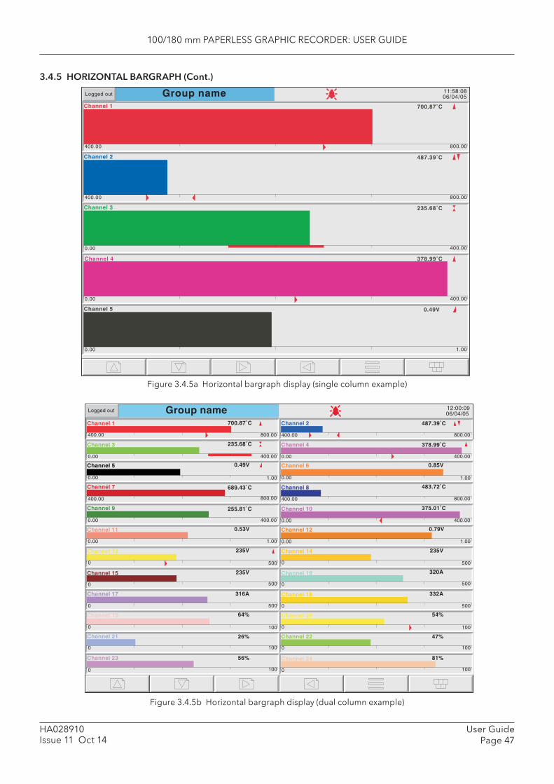
100/180 mm PAPERLESS GRAPHIC RECORDER: USER GUIDE
User GuidePage 47
HA028910Issue 11 Oct 14
3.4.5 HORIZONTAL BARGRAPH (Cont.)
Figure 3.4.5a Horizontal bargraph display (single column example)
Figure 3.4.5b Horizontal bargraph display (dual column example)
Group name 11:58:0806/04/05
Channel 1
400.00 800.00
700.87˚C
Channel 2
400.00 800.00
487.39˚C
Channel 3
0.00 400.00
235.68˚C
Channel 4
0.00 400.00
378.99˚C
Channel 5
0.00 1.00
0.49V
Logged out
Group name 12:00:0906/04/05
Logged out
Channel 1
400.00 800.00
700.87˚CChannel 2
400.00 800.00
Channel 3 700.87˚CChannel 4
0.00 400.00
Channel 5
0.00 1.00
700.87˚CChannel 6
Channel 7
400.00 800.00
700.87˚CChannel 8
400.00 800.00
Channel 9
0.00 400.00
700.87˚CChannel 10
0.00 400.00
Channel 11
0.00 1.00
700.87˚CChannel 12
0.00 1.00
Channel 13
0 500
700.87˚CChannel 14
0 500
Channel 15
0 500
700.87˚CChannel 16
0 500
Channel 17
0 500
700.87˚CChannel 18
0 500
Channel 19
0 100
700.87˚CChannel 20
0 100
Channel 21
0 100
700.87˚CChannel 22
0 100
Channel 23
0 100
700.87˚CChannel 24
0 100
0.49V
0.53V
235V
235V
316A
64%
26%
56%
0.85V
0.79V
235V
320A
332A
54%
47%
81%
0.00 1.00
0.00 400.00
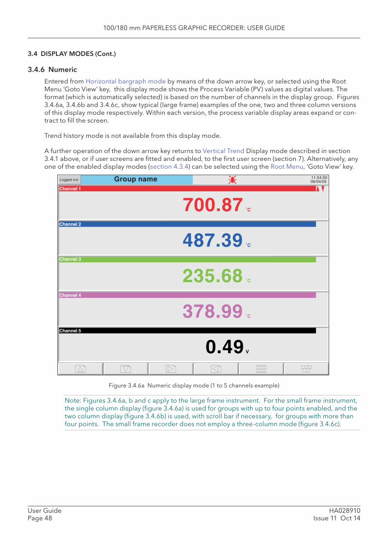
100/180 mm PAPERLESS GRAPHIC RECORDER: USER GUIDE
HA028910Issue 11 Oct 14
User GuidePage 48
3.4 DISPLAY MODES (Cont.)
3.4.6 Numeric
Entered from Horizontal bargraph mode by means of the down arrow key, or selected using the Root Menu ‘Goto View’ key, this display mode shows the Process Variable (PV) values as digital values. The format (which is automatically selected) is based on the number of channels in the display group. Figures 3.4.6a, 3.4.6b and 3.4.6c, show typical (large frame) examples of the one, two and three column versions of this display mode respectively. Within each version, the process variable display areas expand or con-tract to fi ll the screen.
Trend history mode is not available from this display mode.
A further operation of the down arrow key returns to Vertical Trend Display mode described in section 3.4.1 above, or if user screens are fi tted and enabled, to the fi rst user screen (section 7). Alternatively, any one of the enabled display modes (section 4.3.4) can be selected using the Root Menu, ‘Goto View’ key.
Figure 3.4.6a Numeric display mode (1 to 5 channels example)
Note: Figures 3.4.6a, b and c apply to the large frame instrument. For the small frame instrument, the single column display (fi gure 3.4.6a) is used for groups with up to four points enabled, and the two column display (fi gure 3.4.6b) is used, with scroll bar if necessary, for groups with more than four points. The small frame recorder does not employ a three-column mode (fi gure 3.4.6c).
Group nameChannel 1
11:54:5006/04/05Logged out
Channel 2
Channel 4
Channel 5
487.39
235.68
378.99
0.49
700.87
Channel 3
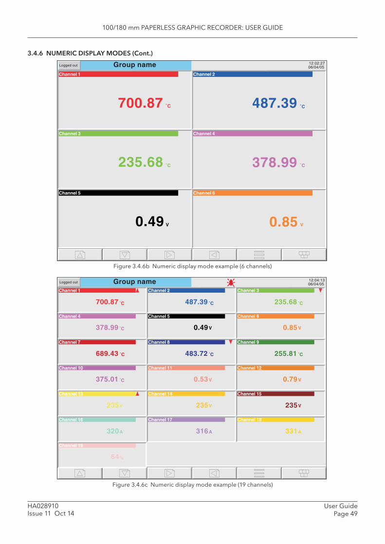
100/180 mm PAPERLESS GRAPHIC RECORDER: USER GUIDE
User GuidePage 49
HA028910Issue 11 Oct 14
3.4.6 NUMERIC DISPLAY MODES (Cont.)
Figure 3.4.6b Numeric display mode example (6 channels)
Figure 3.4.6c Numeric display mode example (19 channels)
Group name 12:02:2706/04/05
Channel 1
Channel 3
Channel 5
Channel 2
Channel 4
Channel 6
V
487.39
378.99
0.85
235.68
0.49
Logged out
700.87
Group nameChannel 1
700.87
Channel 2
487.39
Channel 3
235.68
12:04:1306/04/05Logged out
Channel 4
378.99
Channel 5
0.49 V
Channel 6
0.85 V
Channel 7
689.43
Channel 8
483.72 255.81
Channel 10
375.01
Channel 11
0.53 V
Channel 12
0.79 V
Channel 13
235V
Channel 14
235V
Channel 15
235V
Channel 16
320A
Channel 17
316A
Channel 18
331A
Channel 19
64%
Channel 9
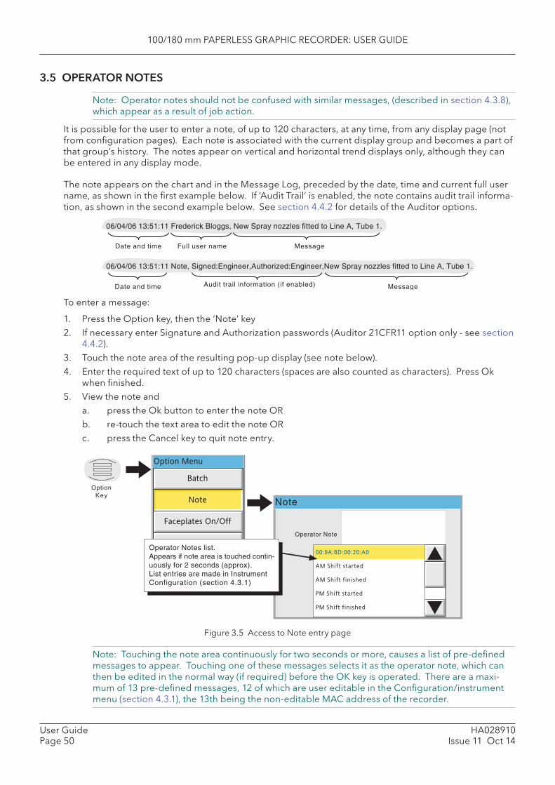
100/180 mm PAPERLESS GRAPHIC RECORDER: USER GUIDE
HA028910Issue 11 Oct 14
User GuidePage 50
3.5 OPERATOR NOTES
Note: Operator notes should not be confused with similar messages, (described in section 4.3.8), which appear as a result of job action.
It is possible for the user to enter a note, of up to 120 characters, at any time, from any display page (not from confi guration pages). Each note is associated with the current display group and becomes a part of that group’s history. The notes appear on vertical and horizontal trend displays only, although they can be entered in any display mode.
The note appears on the chart and in the Message Log, preceded by the date, time and current full user name, as shown in the fi rst example below. If ‘Audit Trail’ is enabled, the note contains audit trail informa-tion, as shown in the second example below. See section 4.4.2 for details of the Auditor options.
Figure 3.5 Access to Note entry page
Note: Touching the note area continuously for two seconds or more, causes a list of pre-defi ned messages to appear. Touching one of these messages selects it as the operator note, which can then be edited in the normal way (if required) before the OK key is operated. There are a maxi-mum of 13 pre-defi ned messages, 12 of which are user editable in the Confi guration/instrument menu (section 4.3.1), the 13th being the non-editable MAC address of the recorder.
Note
Operator Note
OptionKey
Option Menu
Batch
Note
Faceplates On/Off
Enter History
Channel Cycling Off00:0A:8D:00:20:A0
AM Shift started
AM Shift finished
PM Shift started
PM Shift finished
Operator Notes list.Appears if note area is touched contin-uously for 2 seconds (approx).List entries are made in InstrumentConfiguration (section 4.3.1)
To enter a message:
1. Press the Option key, then the ‘Note’ key2. If necessary enter Signature and Authorization passwords (Auditor 21CFR11 option only - see section
4.4.2). 3. Touch the note area of the resulting pop-up display (see note below).4. Enter the required text of up to 120 characters (spaces are also counted as characters). Press Ok
when fi nished.5. View the note and a. press the Ok button to enter the note OR b. re-touch the text area to edit the note OR c. press the Cancel key to quit note entry.
Date and time MessageFull user name
06/04/06 13:51:11 Frederick Bloggs, New Spray nozzles fitted to Line A, Tube 1.
Date and time MessageAudit trail information (if enabled)
06/04/06 13:51:11 Note, Signed:Engineer,Authorized:Engineer,New Spray nozzles fitted to Line A, Tube 1.
100/180 mm PAPERLESS GRAPHIC RECORDER: USER GUIDE
User GuidePage 51
HA028910Issue 11 Oct 14
4 SETTING UP THE RECORDERAs described in the ‘Access to Confi guration’ (section 3.3.1) above, the setting-up of the recorder is di-vided into the following areas:
Archive Section 4.1 - Allows manual archiving of data to a memory device or to a remote host (FTP transfer).
Save/restore Section 4.2 - Allows new confi gurations to be created and saved, and saved confi gurations to be ‘restored’. Save/Restore also allows the importing and exporting of User Linearisa-tion Tables and, if the relevant options are fi tted, User Screens and Printer Drivers.
Confi g Section 4.3 - This is the major channel/alarm option etc. area of confi guration. Security Section 4.4 - Allows passwords to be entered and edited and allows the Engineer-level
password holder to enable/disable areas of confi guration to Operator-level password holders. New users can be added, with their own user names, passwords and access level permissions.
Network Section 4.5 - This area sets up the IP address/host names etc. used in FTP transfer, Bridge and SNTP applications.
System Section 4.6 - Allows a) Time and date to be set (Clock). b) Language, date/time format, time zone, and daylight saving start and fi nish dates to
be set (Locale). c) Software upgrades to be carried out (Upgrade). d) Input channels to be adjusted for errors in transducer inputs (Input Adjust). e) Output channels (if fi tted) to be adjusted (Output Adjust - see section 9.4). f) A Master Comms Diagnostics page to be displayed (if Master Comms option fi tted
and enabled). g) A Network diagnostics page to be displayed (Ethernet diagnostics). h) Confi guration items (e.g. input channels) to be copied, to speed up confi guration
(Copy). i) Search criteria to be entered to allow the user to locate trigger sources for a specifi c
job (Job search). j) The appearance of the display screens to be customised (Customise). k) Details of the hardware and software associated with the recorder to be displayed
(About).
Note: In all the following descriptions, if a change is made to a menu item, then the item text changes to red, until it is ‘applied’
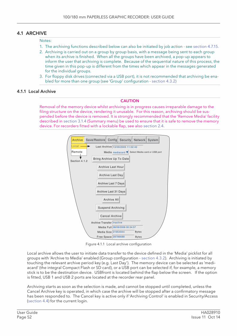
100/180 mm PAPERLESS GRAPHIC RECORDER: USER GUIDE
HA028910Issue 11 Oct 14
User GuidePage 52
4.1 ARCHIVENotes:1. The archiving functions described below can also be initiated by job action - see section 4.7.15.2. Archiving is carried out on a group by group basis, with a message being sent to each group
when its archive is fi nished. When all the groups have been archived, a pop-up appears to inform the user that archiving is complete. Because of the sequential nature of this process, the time given in this pop-up is different from the times which appear in the messages generated for the individual groups.
3. For fl oppy disk drives (connected via a USB port), it is not recommended that archiving be ena-bled for more than one group (see ‘Group’ confi guration - section 4.3.2)
4.1.1 Local Archive
CAUTIONRemoval of the memory device whilst archiving is in progress causes irreparable damage to the fi ling structure on the device, rendering it unusable. For this reason, archiving should be sus-pended before the device is removed. It is strongly recommended that the ‘Remove Media’ facility described in section 3.1.4 (Summary menu) be used to ensure that it is safe to remove the memory device. For recorders fi tted with a lockable fl ap, see also section 2.4.
Figure 4.1.1 Local archive confi guration
Local archive allows the user to initiate data transfer to the device defi ned in the ‘Media’ picklist for all groups with ‘Archive to Media’ enabled (Group confi guration - section 4.3.2). Archiving is initiated by touching the relevant archive period key (e.g. Last Day’). The memory device can be selected as ‘medi-acard’ (the integral Compact Flash or SD card), or a USB port can be selected if, for example, a memory stick is to be the destination device. USBfront is located behind the fl ap below the screen. If the option is fi tted, USB 1 and USB 2 ports are located at the recorder rear panel.
Archiving starts as soon as the selection is made, and cannot be stopped until completed, unless the Cancel Archive key is operated, in which case the archive will be stopped after a confi rmatory message has been responded to. The Cancel key is active only if ‘Archiving Control’ is enabled in Security/Access (section 4.4) for the current login.
Archive SystemSave/Restore Config Security Network
Section 4.1.2
Last Archive
Archive Last Hour
Bytes
Bytes
Archive Last Day
Archive Last 7 Days
Archive Last 31 Days
Archive All
Suspend Archiving
Cancel Archive
Bring Archive Up To Date
Archive Transfer
Media Size
Free Space
Inactive
31954944
28786688
13/09/2005 11:02:42
Media mediacard Select Media card or USB port
Media Full 08/09/2006 00:34:57
Local
Remote

100/180 mm PAPERLESS GRAPHIC RECORDER: USER GUIDE
User GuidePage 53
HA028910Issue 11 Oct 14
4.1.1 LOCAL ARCHIVE (Cont.)
BRING ARCHIVE UP TO DATE
This causes the recorder to archive all history fi les created since the last manual or automatic (section 4.3.5) archive.
ARCHIVE ALL
This causes the recorder to archive all its history fi les.
If the memory device becomes full before archiving is complete, archiving pauses and a pop-up request appears, asking for a replacement. If this request is not responded to within 10 minutes of its appear-ance, archiving is aborted.
Unattended archiving can be paused by the user (e.g. to change media without losing data) by operating the ‘Suspend Archiving’ / ‘Resume Archiving’ button. Any archiving in progress is allowed to complete before the ‘Suspend Archiving’ request takes effect. Transfer activity is indicated in the ‘Archive transfer’ window.
Below the selection buttons are a number of status windows relating to the selected memory device. ‘ Media Full’ is an estimate, based on the current confi guration, of when the memory device will become full. The meanings of the ‘Media Size’ and ‘Free Space’ values are self evident.
If automatic archiving is active (section 4.3.5), then automatic and manual archives will operate on a fi rst come-fi rst served basis. Some fi les will be saved twice in such a circumstance, the later archive’s fi les overwriting any earlier archive’s fi les which have the same name.
ARCHIVING WITH THE LOCKABLE FLAP OPTION
For recorders fi tted with the lockable fl ap (section 2.4) it should be noted that when the fl ap is opened, archiving is automatically suspended. It is therefore necessary to press on the ‘Resume Archiving’ key before any attempt is made to carry out a demand archive.
Before removing the memory device, archiving should be suspended again, using the ‘ Suspend Archive’ key. This ensures that the memory device can be safely removed.
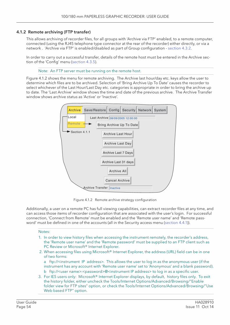
100/180 mm PAPERLESS GRAPHIC RECORDER: USER GUIDE
HA028910Issue 11 Oct 14
User GuidePage 54
4.1.2 Remote archiving (FTP transfer)
This allows archiving of recorder fi les, for all groups with ‘Archive via FTP’ enabled, to a remote computer, connected (using the RJ45 telephone type connector at the rear of the recorder) either directly, or via a network . ‘Archive via FTP’ is enabled/disabled as part of Group confi guration - section 4.3.2.
In order to carry out a successful transfer, details of the remote host must be entered in the Archive sec-tion of the ‘Confi g’ menu (section 4.3.5).
Note: An FTP server must be running on the remote host.
Figure 4.1.2 shows the menu for remote archiving. The Archive last hour/day etc. keys allow the user to determine which fi les are to be archived. Selection of ‘Bring Archive Up To Date’ causes the recorder to select whichever of the Last Hour/Last Day etc. categories is appropriate in order to bring the archive up to date. The ‘Last Archive’ window shows the time and date of the previous archive. The Archive Transfer window shows archive status as ‘Active’ or ‘Inactive’.
Figure 4.1.2 Remote archive strategy confi guration
Additionally, a user on a remote PC has full viewing capabilities, can extract recorder fi les at any time, and can access those items of recorder confi guration that are associated with the user’s login. For successful connection, ‘Connect from Remote’ must be enabled and the ‘Remote user name’ and ‘Remote pass-word’ must be defi ned in one of the accounts (all in the Security access menu (section 4.4.1)).
Notes:1. In order to view history fi les when accessing the instrument remotely, the recorder’s address,
the ‘Remote user name’ and the ‘Remote password’ must be supplied to an FTP client such as PC Review or Microsoft® Internet Explorer.
2. When accessing fi les using Microsoft® Internet Explorer, the address (URL) fi eld can be in one of two forms:
a ftp://<instrument IP address>. This allows the user to log in as the anonymous user (if the instrument has any account with ‘Remote user name’ set to ‘Anonymous’ and a blank password).
b ftp://<user name>:<password>@<instrument IP address> to log in as a specifi c user.3. For IE5 users only: Microsoft® Internet Explorer displays, by default, history fi les only. To exit
the history folder, either uncheck the Tools/Internet Options/Advanced/Browsing/”Enable folder view for FTP sites” option, or check the Tools/Internet Options/Advanced/Browsing/”Use Web based FTP” option.
Archive SystemSave/Restore Config Security Network
Section 4.1.1
Last Archive
Archive Last Hour
Archive Transfer
Archive Last Day
Archive Last 7 Days
Archive Last 31 days
Archive All
Cancel Archive
Bring Archive Up To Date
08/09/2005 12:00:00
Inactive
Local
Remote
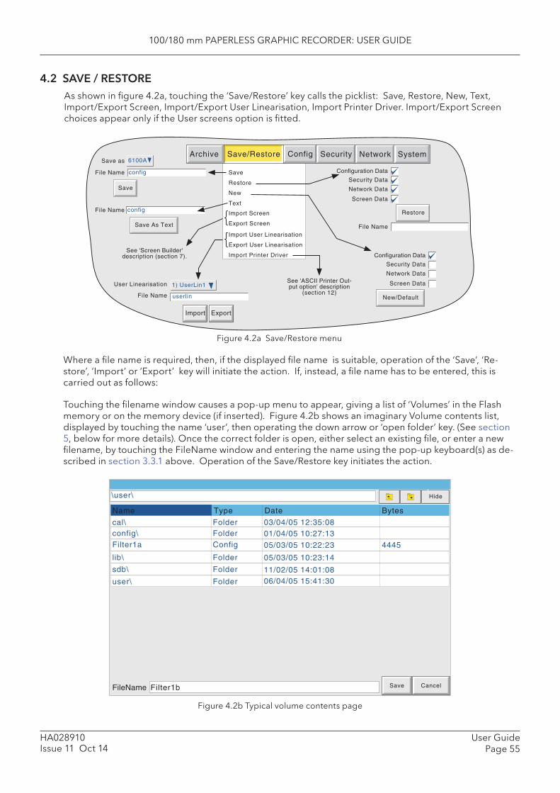
100/180 mm PAPERLESS GRAPHIC RECORDER: USER GUIDE
User GuidePage 55
HA028910Issue 11 Oct 14
4.2 SAVE / RESTOREAs shown in fi gure 4.2a, touching the ‘Save/Restore’ key calls the picklist: Save, Restore, New, Text, Import/Export Screen, Import/Export User Linearisation, Import Printer Driver. Import/Export Screen choices appear only if the User screens option is fi tted.
Figure 4.2a Save/Restore menu
Where a fi le name is required, then, if the displayed fi le name is suitable, operation of the ‘Save’, ‘Re-store’, ‘Import’ or ‘Export’ key will initiate the action. If, instead, a fi le name has to be entered, this is carried out as follows:
Touching the fi lename window causes a pop-up menu to appear, giving a list of ‘Volumes’ in the Flash memory or on the memory device (if inserted). Figure 4.2b shows an imaginary Volume contents list, displayed by touching the name ‘user’, then operating the down arrow or ‘open folder’ key. (See section 5, below for more details). Once the correct folder is open, either select an existing fi le, or enter a new fi lename, by touching the FileName window and entering the name using the pop-up keyboard(s) as de-scribed in section 3.3.1 above. Operation of the Save/Restore key initiates the action.
Figure 4.2b Typical volume contents page
Save
Restore
New
Text
File Name
Network Data
Screen Data
Security Data
Configuration Data
Restore
New/Default
Network Data
Screen Data
Security Data
Configuration Data
File Name
Save As Text
Archive SystemSave/Restore Config Security Network
Import Screen
Export Screen
See 'Screen Builder'description (section 7).
Import User Linearisation
Export User Linearisation
User Linearisation
File Name
Import
1) UserLin1
userlin
Export
Import Printer Driver
See 'ASCII Printer Out-put option' description
(section 12)
File Name
Save
Save as
config
config
6100A
Hide\user\
TypeName
cal\config\
lib\
FolderFolder
Folder
Save CancelFileName Filter1b
sdb\ Folder
user\ Folder
Date
03/04/05 12:35:0801/04/05 10:27:13
05/03/05 10:23:14
11/02/05 14:01:0806/04/05 15:41:30
Filter1a Config 05/03/05 10:22:23
Bytes
4445
100/180 mm PAPERLESS GRAPHIC RECORDER: USER GUIDE
HA028910Issue 11 Oct 14
User GuidePage 56
4.2.1 Save
Touching this item allows the current confi guration to be saved in the recorder’s memory. Files saved in this way are not in a ‘readable’ format and are used only for archive /security purposes or for transfer to another, similar, recorder.
SAVE AS
This selection box allows a confi guration to be saved, if required, in a format suitable for importing into previous recorder models. The default is always the current instrument.
4.2.2 Restore
Touching this item allows the user to select or type-in a previously saved confi guration fi le name, which will then be used as the current confi guration. Touching the ‘Restore’ key completes the operation. Check boxes allow one or more of Confi guration Data, Security data (note 3), Network data and Screen data to be chosen for the restore function.
Notes:1 Screen data restores faceplate status for vertical trend and vertical bargraph modes, and user
screen information (if the option is fi tted).2. If archiving is in progress when a ‘Restore’ is requested, the Restore operation will be delayed
until the archive is complete (maybe several minutes). If required, the ‘Cancel Archive’ key (sec-tion 4.1 above) can be used to speed up the Restore process, at the cost of losing the archive data.
3. If ‘Centralised Security’ is active (part of Security/Management confi guration - section 4.4.2) ‘Security Data’ is not selectable (either for ‘Restore’ or for ‘New’ (below)).
4. If the fi le to be restored has been created using ‘C-Edit’ software, each of the characters used in the fi le name must lie within the unicode range 0 to 255, or the fi le name might not be dis-played correctly.
4.2.3 New
Touching this item causes the factory entered default confi guration to be loaded for use, or for editing. Operation of the New/Default key completes the operation. Tick boxes allow one or more of Confi gura-tion Data, Security data (note 3 above) and Network data to be chosen for the restore default function; only those items which are ticked are replaced by default values.
For recorders with the User Screens option (section 7), a further tick box is displayed - ‘Screen Data’
4.2.4 Text
This is identical to the ‘Save’ function described above, but the confi guration is saved in ASCII format, and can be transferred to a computer and read, printed etc. as required. It is not possible, using this means, to modify the confi guration and then re-load it.
4.2.5 Import screen
This fi eld appears only if the User Screens option (section 7) is fi tted, and allows a previously exported User Screen fi le to be imported.
4.2.6 Export screen
This fi eld appears only if the User Screens option (section 7) is fi tted, and allows a User Screen to be ex-ported to a removable memory device or to the internal Flash memory. The exported screen can subse-quently be imported either into this recorder or into a different recorder.
100/180 mm PAPERLESS GRAPHIC RECORDER: USER GUIDE
User GuidePage 57
HA028910Issue 11 Oct 14
4.2.7 Import User Linearisation
The Import Linearisation feature allows linearisation tables to be imported either from the Compact Flash/SD card, USB device or if Bridge ‘Full’ software is fi tted, directly from the host PC.
Touching the User Linearisation fi eld allows the user to select which of ‘UserLin1’ to ‘UserLin4’ is to con-tain the imported fi le.
Touching the File Name fi eld, calls a popup menu similar to that shown in fi gure 4.2b. This allows the user to select the table to be imported.
The fi le must be comma separated ASCII as follows:
n,X1,Y1X2.Y2X3,Y3 . .Xn,Yn
where ‘n’ is the total number of XY pairs in the table, and or each pair, X is the input value, and Y is the linearised value corresponding to X. See section 4.3.9 for full details.
Note: Imported linearisation tables will not become effective until after the next confi guration ‘Apply’ operation.
4.2.8 Export User Linearisation
Similar to ‘Import user Linearisation’, above, the Export Linearisation feature allows linearisation tables created in the recorder to be exported either via the Compact Flash/SD card or if Bridge ‘Full’ software is fi tted, directly to the host PC. See section 4.3.9 for full details.
4.2.9 Import printer driver
Similar to ‘Import user Linearisation’, above, this allows driver (.uhi) fi les for new printer types to be im-ported either via the Compact Flash/SD card, or USB memory stick, or if the Bridge ‘Full’ option is fi tted, directly from the host PC. See section 12 for further details.
Note: Imported printer drivers do not become effective until after the next confi guration ‘Apply’ operation.

100/180 mm PAPERLESS GRAPHIC RECORDER: USER GUIDE
HA028910Issue 11 Oct 14
User GuidePage 58
4.3 CONFIG KEYTouching this key calls the top level confi guration pick list:
Instrument, Groups, Channels, Views, Archive, Events,Event Buttons,Messages,
User Linearisations,Batch,Maths,Totalisers,Counters,Timers,Connections,
Master Comms,Output Channels,Demand Writes,Emails,Reports,EtherNet/IP ServerOptions
Notes:1. Figure 4.3b gives an overview of the confi guration menus.2. If an option is not fi tted, it does not appear in the above list.
When making changes to the confi guration the name of each changed parameter is displayed in red (instead of the normal black) until the ‘Apply/Discard’ key has been operated. For example, in channel confi guration, if a thermocouple were to be changed from Type J to Type K, ‘Lin Type’ would appear in red, until the Apply key is operated.
Should an attempt be made to leave confi guration with unsaved changes, a warning message appears, allowing the user to apply the changes, to discard the changes or to return to confi guration (Cancel).
Config
Apply Discard Cancel
Data Has Been Modified
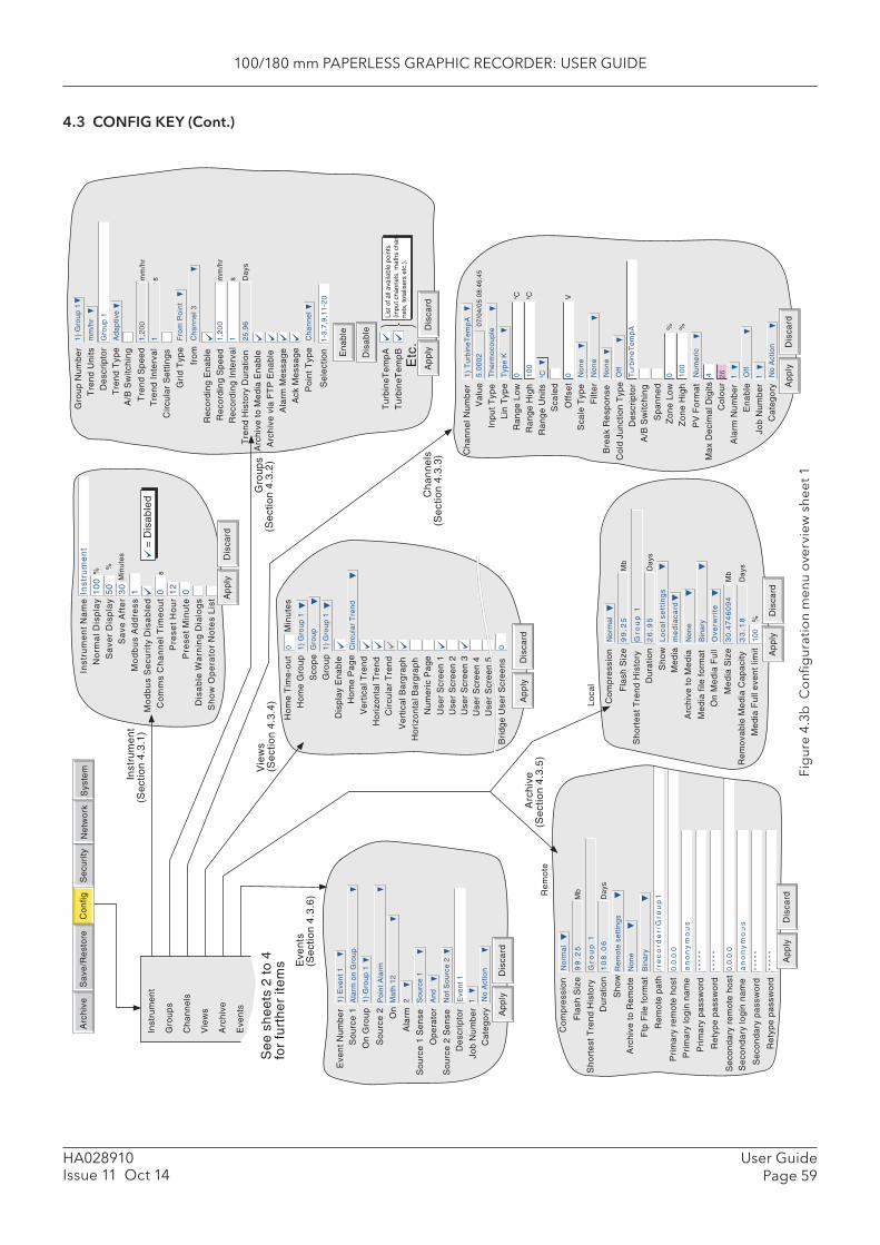
100/180 mm PAPERLESS GRAPHIC RECORDER: USER GUIDE
User GuidePage 59
HA028910Issue 11 Oct 14
4.3 CONFIG KEY (Cont.)
Fig
ure
4.3b
Co
nfi g
urat
ion
men
u o
verv
iew
she
et 1
Ap
ply
Dis
card
Ala
rm M
ess
ag
e
Re
cord
ing
Sp
ee
dR
eco
rdin
g I
nte
rva
l
Arc
hiv
e t
o M
ed
ia E
na
ble
Arc
hiv
e v
ia F
TP
En
ab
le
Tre
nd
His
tory
Du
ratio
n
Re
cord
ing
En
ab
le
Ack
Me
ssa
ge
Tu
rbin
eT
em
pA
Tu
rbin
eT
em
pB
Etc
.11,2
00
mm
/hr
s
List
of a
ll av
aila
ble
poin
ts
(inpu
t cha
nnel
s, m
aths
cha
n-ne
ls, t
otal
iser
s et
c.).
25
.96
Da
ys
Tre
nd
Un
itsD
esc
rip
tor
Tre
nd
Sp
ee
dT
ren
d I
nte
rva
l
Gro
up
Nu
mb
er
Tre
nd
Typ
e
mm
/hr
11,2
00
mm
/hr
s
Gro
up
1
1)
Gro
up
1
Ad
ap
tive
Cir
cula
r S
ett
ing
s
Gri
d T
ype
Fro
m P
oin
t
fro
mC
ha
nn
el 3
A/B
Sw
itch
ing
Po
int
Typ
eC
ha
nn
el
Se
lect
ion
1-3
,7,9
,11
-20
En
ab
le
Dis
ab
le
%
%
Min
ute
s
s
= D
isa
ble
d
0 0
Inst
rum
en
t N
am
eIn
stru
me
nt
No
rma
l Dis
pla
y1
00
S
ave
r D
isp
lay
50
S
ave
Aft
er
30
M
od
bu
s A
dd
ress
1
Mo
db
us
Se
curi
ty D
isa
ble
d
Co
mm
s C
ha
nn
el T
ime
ou
t0
P
rese
t H
ou
r1
2
Pre
set
Min
ute
0
Dis
ab
le W
arn
ing
Dia
log
s S
ho
w O
pe
rato
r N
ote
s L
ist
Ap
ply
Dis
card
On
Me
dia
Fu
ll
Me
dia
Siz
e3
0.4
74
60
94
Mb
Ov
erw
rite
Me
dia
Fu
ll e
ven
t lim
it
Re
mo
vab
le M
ed
ia C
ap
aci
ty3
3.1
8D
ays
10
0%
Arc
hiv
e t
o M
ed
ia
Co
mp
ress
ion
No
rma
l
Fla
sh S
ize
99
.25
Mb
Sh
ort
est
Tre
nd
His
tory
Gro
up
1
Sh
ow
Lo
ca
l s
ett
ing
s
Du
ratio
n2
6.9
5D
ays
No
ne
Me
dia
file
fo
rma
tB
ina
ry
Me
dia
me
dia
ca
rd
Ap
ply
Dis
card
Job
Nu
mb
er
1
Ca
teg
ory
No
Act
ion
Max
Dec
imal
Dig
its4
Co
lou
rA
larm
Nu
mb
er
1
En
ab
leO
ff
26
PV
Fo
rma
tN
um
eri
c
Va
lue
5.0
00
2
Inp
ut
Typ
eT
he
rmo
cou
ple
Lin
Typ
eT
ype
K
Ra
ng
e L
ow
0C
Ra
ng
e H
igh
10
0C
Ra
ng
e U
nits
C
Sca
led
Off
set
0V
Filt
er
No
ne
Bre
ak
Re
spo
nse
No
ne
Col
d Ju
nctio
n T
ype
Off
De
scri
pto
rT
urb
ine
Te
mp
A
Sp
an
ne
d
Ch
an
ne
l Nu
mb
er
1)
Tu
rbin
eT
em
pA
07
/04
/05
08
:46
:45
Sca
le T
ype
No
ne
A/B
Sw
itch
ing
Zo
ne
Lo
w0
%
Zo
ne
Hig
h%
10
0
Gro
up
s (S
ect
ion
4.3
.2)
Vie
ws
(Se
ctio
n 4
.3.4
)
Ho
me
Tim
e-o
ut
Ho
me
Gro
up
Sco
pe
Gro
up
Dis
pla
y E
na
ble
Ho
me
Pa
ge
Ve
rtic
al T
ren
dH
ori
zon
tal T
ren
d
Ve
rtic
al B
arg
rap
hH
ori
zon
tal B
arg
rap
hN
um
eri
c P
ag
eU
ser
Scr
ee
n 1
Use
r S
cre
en
2U
ser
Scr
ee
n 3
Use
r S
cre
en
4
1)
Gro
up
1
0 Gro
up
1)
Gro
up
1
Cir
cula
r T
ren
d
Min
ute
s
Cir
cula
r T
ren
d
Use
r S
cre
en
5
Ap
ply
Dis
card
Lo
cal
Arc
hiv
e
(Se
ctio
n 4
.3.5
)R
em
ote
Arc
hiv
e t
o R
em
ote
No
ne
Re
mo
te p
ath
Sh
ow
Re
mo
te s
ett
ing
s
0.0
.0.0
Pri
ma
ry r
em
ote
ho
st
Pri
ma
ry lo
gin
na
me
an
on
ym
ou
s
Pri
ma
ry p
ass
wo
rd**
***
Re
typ
e p
ass
wo
rd**
***
0.0
.0.0
Se
con
da
ry r
em
ote
ho
stS
eco
nd
ary
log
in n
am
ea
no
ny
mo
us
Se
con
da
ry p
ass
wo
rd**
***
Re
typ
e p
ass
wo
rd**
***
/re
co
rde
r/G
rou
p1
Co
mp
ress
ion
No
rma
l
Fla
sh S
ize
99
.25
Mb
Sh
ort
est
Tre
nd
His
tory
Gro
up
1
Du
ratio
n1
08
.06
Da
ys
Ftp
File
fo
rma
tB
ina
ry
Ap
ply
Dis
card
Inst
rum
en
t (S
ect
ion
4.3
.1)
Se
e s
he
ets
2 t
o 4
fo
r fu
rth
er
item
s
Arc
hiv
eS
yste
mS
ave
/Re
sto
reC
on
figS
ecu
rity
Ne
two
rk
Ch
an
ne
ls
(Se
ctio
n 4
.3.3
)
Ap
ply
Dis
card
Eve
nt
Nu
mb
er
1)
Eve
nt
1
So
urc
e 1
De
scri
pto
rE
ven
t 1
Job
Nu
mb
er
1
Ca
teg
ory
No
Act
ion
Ala
rm o
n G
rou
p
On
Gro
up
1)
Gro
up
1
So
urc
e 2
Po
int
Ala
rm
On
Ma
th 1
2
Ala
rm2
So
urc
e 1
Se
nse
Op
era
tor
So
urc
e 2
Se
nse
So
urc
e 1
An
d
No
t S
ou
rce
2
Inst
rum
en
t G
rou
ps
Ch
an
ne
ls
Vie
ws
Arc
hiv
e
Eve
nts
Bri
dg
e U
ser
Scr
ee
ns
0
Eve
nts
(S
ect
ion
4.3
.6)
Ap
ply
Dis
card
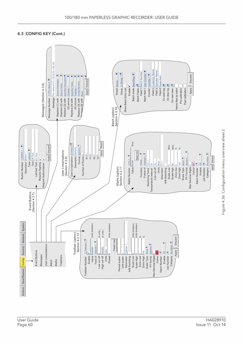
100/180 mm PAPERLESS GRAPHIC RECORDER: USER GUIDE
HA028910Issue 11 Oct 14
User GuidePage 60
4.3 CONFIG KEY (Cont.)
Fig
ure
4.3b
Co
nfi g
urat
ion
men
u o
verv
iew
she
et 2
������
��� ����
��� ������
����� �
�� ��� ����
�� ��� ���
�� ��� �������
���� ����� �� ����
�������
� ��� � ����!
"����
#������
$�� �
�����$�� �
�% $�� � �
��� ����� �
&�� '� ���
'� ���'� ��� �
����� (
' ����� ����!
����� )
������� ����!
����� �
� ���*����!
���� ��� ���� +��
,������ � ����
,������
-������ .�/ ���
-������ .(/ ���
-������ .)/ ���
.)/ �� ���
-������ .�/ ���
.�/ �� ���
-������ .0/ ���
-������ .1/ ���
�% 2�� *�� � ��
2�� *�� � �� .�/ 3 .(/ 4 .)/ 3 .�/5 .0/
�� ��� #��������
�� ��� ��� �
2������� �
��������� #��������
2������� �
��������� ��� �
'����� -�*�����
���6
"����
#������
,������� 7������ �8)89%
�� � ����
#��������
2���
2�:
+����� 2�:
-�; ��� �������
-�; ��� " ���������
"����
#������
�% �� �
�� �
+�����
��� 2�:
�� 2�:
&��� +�����������
#��������
����
�
� ���� �� <���� =�
>�
=(
)% &���+��)
� �����
( ? ? �
>(
�&���+��)
"����
#������
&��� +������������
7������ �8)8@%
"����*�
�����
��*��-�����
'�����
��� ���
�����6
�*�� ���
7������ �8)8A%
"����
#������
� �����
���� �
�*�� � ��
������B��� 2���
�(�8�
+�� � ���
#��������
�� �
����� +��
?,���
����� 2���
����
C��� ���
?
C��� ����
,�: #������ #����
(
'��� �
"����
� ����
�
������
���
D�� � �����
'������
�� "����
(1
'������ �
A0
E
�??
E
,��� � ����
�% �� �
��� �
)(810
-��� ���
,���
<� ����
�
� �����
2������ �� ����*��
�?
&���
,���
����� ����
1?
"� ��������
,���
"����
#������
2������� � ����
������
"����
� ����
������
D�� � ����
'������
��� �
2��� ��
+�� � ���
F��� � ���
&���
<����
<���� ���
�()�01
�� ���
�� ���
&��� 7�������%
<����� ������
&�� ������
#��������
&��� 7�������%
����� +��
����� F���
&��� 7�������%
&��� 7�������%
C��� +��
C��� F���
E E
,�: #������ #����
'��� �
����� 2���
����
<� ����
�
"� ��������
�% 2������� �
� ���
� �� "����
'������ �
? @@@@@@
&���
? � � 2������� �
? � � �??
� ?� �����
��� 7�����%
������ �8)8�?
,��� 7�����%
������ �8)8��
2������� 7�����%
������ �8)8�(
�*�� ���
,�������
&��� +������������
���
,���
2��������
<�� ����������
<�� ����������
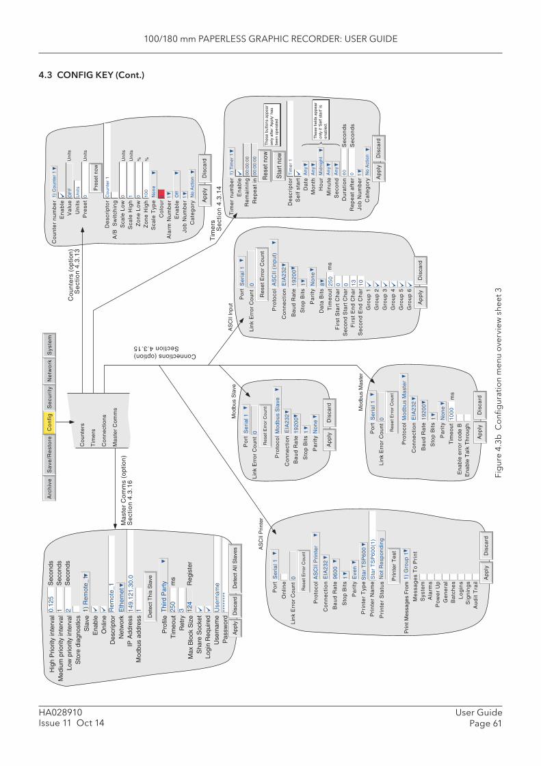
100/180 mm PAPERLESS GRAPHIC RECORDER: USER GUIDE
User GuidePage 61
HA028910Issue 11 Oct 14
4.3 CONFIG KEY (Cont.)
Fig
ure
4.3b
Co
nfi g
urat
ion
men
u o
verv
iew
she
et 3
Arc
hiv
eS
yste
mS
ave
/Re
sto
reC
on
fig
Se
curi
tyN
etw
ork
Tim
er
nu
mb
er
1)
Tim
er
1
En
ab
leR
em
ain
ing S
tart
now
00
:00
:00
De
scri
pto
rT
ime
r 1
Se
lf s
tart
Da
teM
on
th
Re
pe
at
in0
0:0
0:0
0
Res
et n
ow
An
y
An
y
Ap
ply
Dis
card
Se
con
dD
ura
tio
n
Job
Nu
mb
er
Min
ute
Re
pe
at
aft
er
1
Ca
teg
ory
No
Act
ion
Ho
ur
Mid
nig
ht
An
y
An
y
60
Se
con
ds
0S
eco
nd
s
The
se fi
elds
app
ear
only
if 'S
elf s
tart
' is
enab
led.
The
se b
utto
ns a
ppea
ron
ly a
fter
'App
ly' h
asbe
en o
pera
ted
Ap
ply
Dis
card
Co
un
ter
nu
mb
er
En
ab
le
Ala
rm N
um
be
rE
na
ble
Job
Nu
mb
er
Ca
teg
ory
Va
lue
Un
its
Pre
set
Pre
set n
ow
Un
its
De
scri
pto
r
Un
its
Sca
le L
ow
Sca
le H
igh
Un
its
Un
its
Zo
ne
Lo
wZ
on
e H
igh
% %
Co
lou
r
Sca
le T
ype
No
ne
A/B
S
wit
chin
g
1)
Co
un
ter
1
1 Off
1 No
Act
ion
OF
F
Un
its
0 Co
un
ter
1
0 1 0 10
0
0
Pro
toco
l
Lin
k E
rro
r C
ou
nt
Re
set
Err
or
Co
un
t
On
line
Co
nn
ect
ion
Po
rt
Ba
ud
Ra
te
Sto
p B
its
Pa
rity
Pri
nte
r T
ype
Pri
nte
r N
am
e
Pri
nte
r S
tatu
s
Sys
tem
Ala
rms
Po
we
r U
p
Pri
nte
r T
est
Prin
t Mes
sage
s F
rom
Me
ssa
ge
s T
o P
rin
t
Ge
ne
ral
Ba
tch
es
Lo
gin
s
Ap
ply
Dis
card
Sig
nin
gs
Au
dit
Tra
il
AS
CII
Pri
nte
r
0 EIA
23
2
Se
ria
l 1
96
00
1 Eve
n
Sta
r T
SP
60
0
Sta
r T
SP
60
0(1
)
No
t R
esp
on
din
g
1)
Gro
up
1
AS
CII
Prin
ter
Ap
ply
Dis
card
25
0
Ba
ud
Ra
te
Pa
rity
Da
ta B
its
Tim
eo
ut
Fir
st S
tart
Ch
ar
Se
con
d S
tart
Ch
ar
Fir
st E
nd
Ch
ar
Se
con
d E
nd
Ch
ar
Gro
up
1
Gro
up
2
Gro
up
3
Gro
up
4
Gro
up
5
Gro
up
6
19
20
0
1 No
ne
8m
s
0 13
Lin
k E
rro
r C
ou
nt
0 0 10
Re
set
Err
or
Co
un
t
Pro
toco
lA
SC
II (
inp
ut)
Po
rtS
eri
al 1
Co
nn
ect
ion
EIA
23
2
Sto
p B
its
AS
CII
Inpu
t
Ap
ply
Dis
card
Ba
ud
Ra
te
Sto
p B
its
Pa
rity
Tim
eo
ut
ms
En
ab
le e
rro
r co
de
BE
na
ble
Ta
lk T
hro
ug
h
Pro
toco
l
Lin
k E
rro
r C
ou
nt
Re
set
Err
or
Co
un
t
Co
nn
ect
ion
Po
rt
19
20
0
1 No
ne
10
00
Mo
db
us
Ma
ste
r
0 EIA
23
2
Se
ria
l 1
Mod
bus
Mas
ter
Ap
ply
Dis
card
Ba
ud
Ra
te
Sto
p B
its
Pa
rity
Pro
toco
l
Lin
k E
rro
r C
ou
nt
Re
set
Err
or
Co
un
t
Co
nn
ect
ion
Po
rt
19
20
0
1 No
ne
Mo
db
us
Sla
ve
0 EIA
23
2
Se
ria
l 1Mod
bus
Sla
ve
Det
ect T
his
Sla
ve
Hig
h P
riorit
y in
terv
alM
ediu
m p
riorit
y in
terv
alLo
w p
riorit
y in
terv
alS
tore
dia
gnos
tics
Sla
veE
nabl
eO
nlin
eD
escr
ipto
rN
etw
ork
IP A
ddre
ssM
odbu
s ad
dres
s
Pro
file
Tim
eout
Ret
ryM
ax B
lock
Siz
eS
hare
Soc
ket
Logi
n R
equi
red
Use
rnam
eP
assw
ord
0.12
51 2 1)
Rem
ote_
1
Rem
ote_
1
149.
121.
30.0
Eth
erne
t
1 Thi
rd P
arty
250
3 124
ms
Reg
iste
r
Sec
onds
Sec
onds
Sec
onds
Use
rnam
e**
****
**
Det
ect A
ll S
lave
sD
isca
rdA
pply
Co
un
ters
Tim
ers
Co
nn
ect
ion
s
Ma
ste
r C
om
ms
Co
un
ters
(o
ptio
n)
Se
ctio
n 4
.3.1
3
Tim
ers
Se
ctio
n 4
.3.1
4
Connections (option)Section 4.3.15
Ma
ste
r C
om
ms
(op
tion
)S
ect
ion
4.3
.16
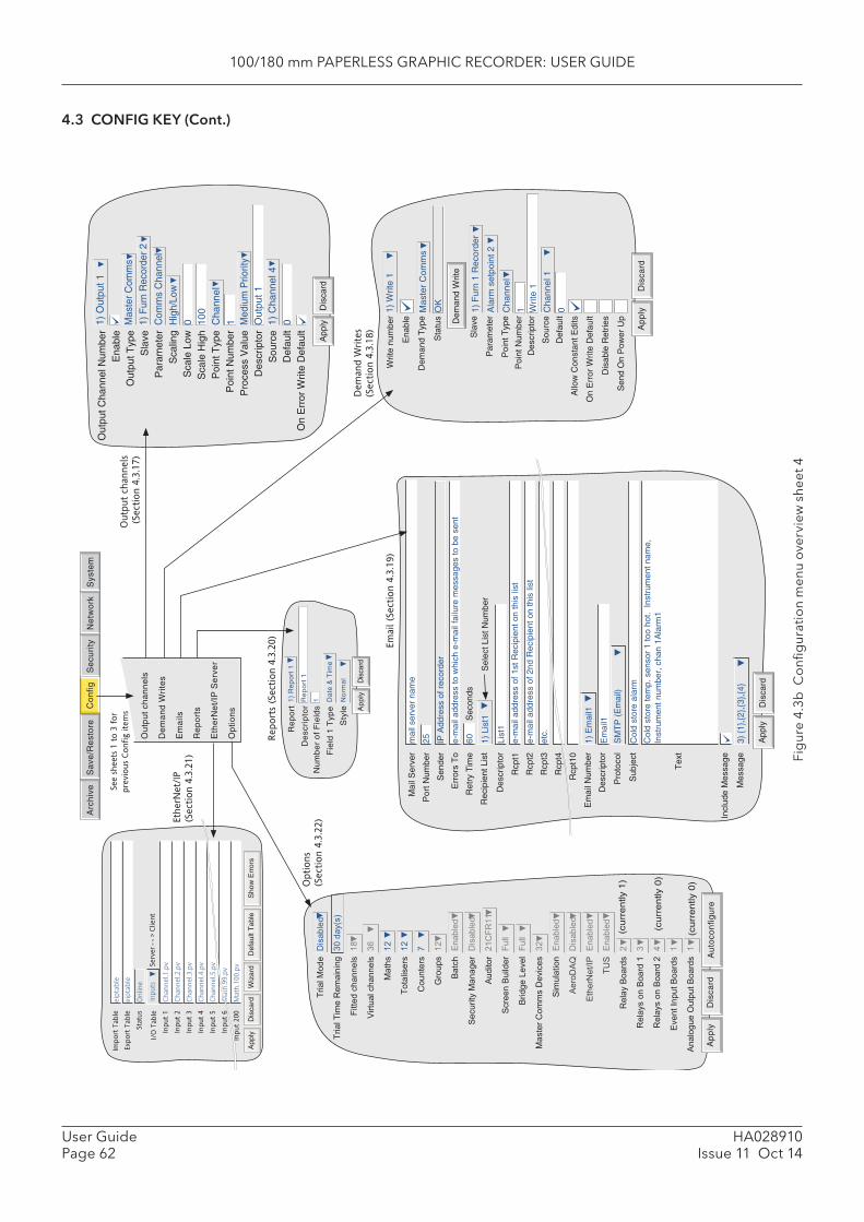
100/180 mm PAPERLESS GRAPHIC RECORDER: USER GUIDE
HA028910Issue 11 Oct 14
User GuidePage 62
4.3 CONFIG KEY (Cont.)
Fig
ure
4.3b
Co
nfi g
urat
ion
men
u o
verv
iew
she
et 4
2���� ,���
#�������
2���� 2��� -��������
)? ���7�%
���� ��������
�9
��� �� ��������
)1
,���
�(
2��������
�(
'� ����
A
$�� ��
�(
���
�������
��� ��� ,������#�������
" ����(�'�-��
������ ������ ��
����� +�*��� ��
,���� '���� #�*����
)(
��� �����
�������
"���#"H
#�������
�������I<
�������
2&�
�������
-���� �����
(
-����� �� ���� �
)
-����� �� ���� (
�
�*�� I�� �����
�
"����� � � � �����
�
(cu
rre
ntly
1)
(cu
rre
ntly
0)
(cu
rre
ntly
0)
Ap
ply
Dis
card
Au
toco
nfig
ure
Out
put C
hann
el N
umbe
r E
nabl
e O
utpu
t Typ
e S
lave
P
aram
eter
S
calin
g S
cale
Low
S
cale
Hig
h P
oint
Typ
e P
oint
Num
ber
Pro
cess
Val
ue
Des
crip
tor
Sou
rce
Def
ault
On
Err
or W
rite
Def
ault
1) O
utpu
t 1
Dis
card
App
lyMas
ter
Com
ms
1) F
urn
Rec
orde
r 2
Com
ms
Cha
nnel
Cha
nnel
Med
ium
Prio
rity
1) C
hann
el 4
Hig
h/Lo
w0 10
0
01 Out
put 1
Import
Table
Export
Table
Sta
tus
I/O
Table
Input
1
Input
2
Input
3
Input
4
Input
5
Input
6
Input
200
eip
table
eip
table
Online
Inputs
Serv
er-->
Client
Channel.1.p
v
Channel.2.p
v
Channel.3.p
v
Channel.4.p
v
Channel.5.p
v
Ch
App
lyD
isca
rdW
izar
dD
efau
lt T
able
Sho
w E
rror
s
Ena
ble
Dem
and
Typ
e
Sta
tus
Ap
ply
Dis
card
Writ
e nu
mbe
r
Dem
and
Writ
e
Sla
ve
Par
amet
er
Poi
nt T
ype
Poi
nt N
umbe
r
Des
crip
tor
Sou
rce
Def
ault
Allo
w C
onst
ant E
dits
Dis
able
Ret
ries
Sen
d O
n P
ower
Up
On
Err
or W
rite
Def
ault
Mas
ter
Com
ms
1) W
rite
1
OK
1) F
urn
1 R
ecor
der
Ala
rm s
etpo
int 2
Cha
nnel
1 Writ
e 1
Cha
nnel
1
0
Re
po
rt
De
scri
pto
rN
um
be
r o
f F
ield
s
Fie
ld 1
Typ
e
Sty
le
1)
Re
po
rt 1
1 Da
te &
Tim
e
No
rma
l
Re
po
rt 1
Ap
ply
Dis
card
Dem
and W
rite
s
(Section 4
.3.1
8)
See s
heets
1 t
o 3
for
�
pre
vio
us
Config ite
ms
Options
(Section 4
.3.2
2)
Mai
l Ser
ver
Por
t Num
ber
Sen
der
Err
ors
To
Ret
ry T
ime
Rec
ipie
nt L
ist
Des
crip
tor
Rcp
t1
Rcp
t2
Rcp
t3
Rcp
t4
Rcp
t10
Em
ail N
umbe
r
Des
crip
tor
Pro
toco
l
Sub
ject
Tex
t
Incl
ude
Mes
sage
Mes
sage
mai
l ser
ver
nam
e
25 IP A
ddre
ss o
f rec
orde
r
e-m
ail a
ddre
ss to
whi
ch e
-mai
l fai
lure
mes
sage
s to
be
sent
60S
econ
ds
1) L
ist1
List
1
e-m
ail a
ddre
ss o
f 1st
Rec
ipie
nt o
n th
is li
st
e-m
ail a
ddre
ss o
f 2nd
Rec
ipie
nt o
n th
is li
st
etc.
1) E
mai
l1
Em
ail1
SM
TP
(E
mai
l)
Col
d st
ore
alar
m
Col
d st
ore
tem
p. s
enso
r 1
too
hot.
Inst
rum
ent n
ame,
In
stru
men
t num
ber,
cha
n 1A
larm
1
3) {
1},{
2},{
3},{
4}
Sel
ect L
ist N
umbe
r
App
lyD
isca
rd
Arc
hiv
eS
yste
mS
ave
/Re
sto
reC
on
figS
ecu
rity
Ne
two
rk
Outp
ut
channels
(Section 4
.3.1
7)
Em
ail (
Section 4
.3.1
9)
Eth
erN
et/
IP
(Section 4
.3.2
1)
Report
s (S
ection 4
.3.2
0)
Ou
tpu
t ch
an
ne
ls
De
ma
nd
Wri
tes
Em
ails
R
ep
ort
s E
the
rNe
t/IP
Se
rve
r O
ptio
ns
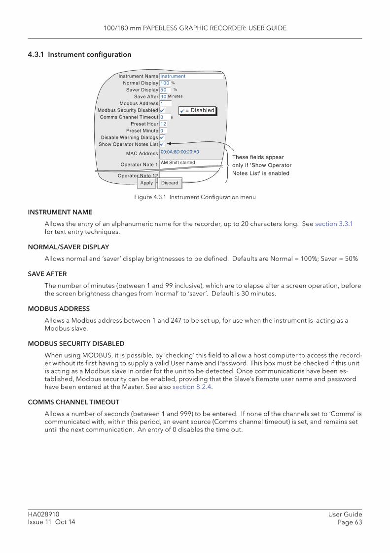
100/180 mm PAPERLESS GRAPHIC RECORDER: USER GUIDE
User GuidePage 63
HA028910Issue 11 Oct 14
4.3.1 Instrument confi guration
%
%
Minutes
s
= Disabled
0
0
Instrument Name InstrumentNormal Display 100
Saver Display 50Save After 30
Modbus Address 1Modbus Security DisabledComms Channel Timeout 0
Preset Hour 12Preset Minute 0
Disable Warning DialogsShow Operator Notes List
00:0A:8D:00:20:A0MAC Address
Operator Note 1
Operator Note 12
Apply Discard
These fields appear
only if 'Show Operator
Notes List' is enabled
AM Shift started
Figure 4.3.1 Instrument Confi guration menu
INSTRUMENT NAME
Allows the entry of an alphanumeric name for the recorder, up to 20 characters long. See section 3.3.1 for text entry techniques.
NORMAL/ SAVER DISPLAY
Allows normal and ‘saver’ display brightnesses to be defi ned. Defaults are Normal = 100%; Saver = 50%
SAVE AFTER
The number of minutes (between 1 and 99 inclusive), which are to elapse after a screen operation, before the screen brightness changes from ‘normal’ to ‘saver’. Default is 30 minutes.
MODBUS ADDRESS
Allows a Modbus address between 1 and 247 to be set up, for use when the instrument is acting as a Modbus slave.
MODBUS SECURITY DISABLED
When using MODBUS, it is possible, by ‘checking’ this fi eld to allow a host computer to access the record-er without its fi rst having to supply a valid User name and Password. This box must be checked if this unit is acting as a Modbus slave in order for the unit to be detected. Once communications have been es-tablished, Modbus security can be enabled, providing that the Slave’s Remote user name and password have been entered at the Master. See also section 8.2.4.
COMMS CHANNEL TIMEOUT
Allows a number of seconds (between 1 and 999) to be entered. If none of the channels set to ‘Comms’ is communicated with, within this period, an event source (Comms channel timeout) is set, and remains set until the next communication. An entry of 0 disables the time out.

100/180 mm PAPERLESS GRAPHIC RECORDER: USER GUIDE
HA028910Issue 11 Oct 14
User GuidePage 64
4.3.1 INSTRUMENT CONFIGURATION (Cont.)
PRESET HOUR
Enter an hours number between 0 and 23 for use with Clock Job - Preset clock.
PRESET MINUTE
Enter a minutes number between 0 and 59 for use with Clock Job - Preset clock.
Note: See section 4.7 for a description of recorder jobs, and section 4.5.1 for further details of time synchronisation.
DISABLE WARNING DIALOGS
Checking this box prevents instrument alarm messages from appearing on the screen.
SHOW OPERATOR NOTES LIST
Enabling this fi eld produces a list of 13 entries which can be used in Operator Notes. The fi rst entry is the MAC address of the recorder and is not editable. The remaining 12 entries (of up to 60 characters each) are freely editable.
Any one of these predefi ned notes can be selected (as described in section 3.5) by touching the Opera-tor Note area continuously for two seconds, then touching the required note from the picklist which ap-pears. Once selected the predefi ned note can be edited before use, like a normal Operator Note. Such editing does not affect the original note entered here in Instrument Confi guration.
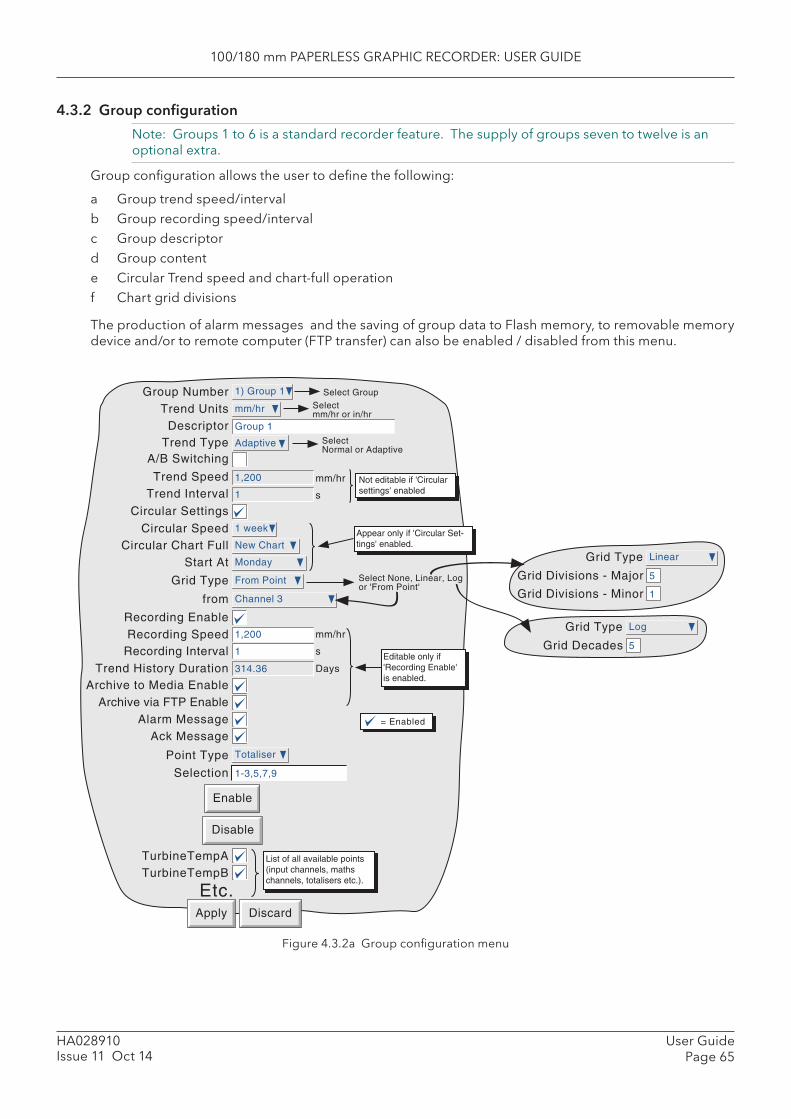
100/180 mm PAPERLESS GRAPHIC RECORDER: USER GUIDE
User GuidePage 65
HA028910Issue 11 Oct 14
4.3.2 Group confi guration
Note: Groups 1 to 6 is a standard recorder feature. The supply of groups seven to twelve is an optional extra.
Group confi guration allows the user to defi ne the following:
a Group trend speed/intervalb Group recording speed/intervalc Group descriptord Group content e Circular Trend speed and chart-full operationf Chart grid divisions
The production of alarm messages and the saving of group data to Flash memory, to removable memory device and/or to remote computer (FTP transfer) can also be enabled / disabled from this menu.
Figure 4.3.2a Group confi guration menu
Grid Type Linear
Grid Divisions - Minor
Grid Divisions - Major 5
1
Apply Discard
Alarm Message
Recording SpeedRecording Interval
Archive to Media EnableArchive via FTP Enable
Trend History Duration
Recording Enable
Ack Message
TurbineTempATurbineTempB
= Enabled
Etc.
1
1,200 mm/hr
s
List of all available points(input channels, mathschannels, totalisers etc.).
314.36 DaysEditable only if'Recording Enable'is enabled.
Trend UnitsDescriptor
Trend SpeedTrend Interval
Group Number
Trend Type
Selectmm/hr or in/hr
mm/hr
1
1,200 mm/hr
s
Group 1
1) Group 1 Select Group
Adaptive
Select None, Linear, Logor 'From Point'
Circular Speed 1 week
Circular Chart Full New Chart
Start At Monday
Appear only if 'Circular Set-tings' enabled.
Circular Settings
Grid Type From Point
from Channel 3
A/B Switching
SelectNormal or Adaptive
Not editable if 'Circularsettings' enabled
Point Type Totaliser
Selection 1-3,5,7,9
Enable
Disable
Grid Type Log
Grid Decades 5
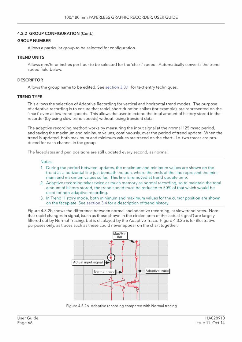
100/180 mm PAPERLESS GRAPHIC RECORDER: USER GUIDE
HA028910Issue 11 Oct 14
User GuidePage 66
4.3.2 GROUP CONFIGURATION (Cont.)
GROUP NUMBER
Allows a particular group to be selected for confi guration.
TREND UNITS
Allows mm/hr or inches per hour to be selected for the ‘chart’ speed. Automatically converts the trend speed fi eld below.
DESCRIPTOR
Allows the group name to be edited. See section 3.3.1 for text entry techniques.
TREND TYPE
This allows the selection of Adaptive Recording for vertical and horizontal trend modes. The purpose of adaptive recording is to ensure that rapid, short duration spikes (for example), are represented on the ‘chart’ even at low trend speeds. This allows the user to extend the total amount of history stored in the recorder (by using slow trend speeds) without losing transient data.
The adaptive recording method works by measuring the input signal at the normal 125 msec period, and saving the maximum and minimum values, continuously, over the period of trend update. When the trend is updated, both maximum and minimum values are traced on the chart - i.e. two traces are pro-duced for each channel in the group.
The faceplates and pen positions are still updated every second, as normal.
Notes:1 During the period between updates, the maximum and minimum values are shown on the
trend as a horizontal line just beneath the pen, where the ends of the line represent the mini-mum and maximum values so far. This line is removed at trend update time.
2. Adaptive recording takes twice as much memory as normal recording, so to maintain the total amount of history stored, the trend speed must be reduced to 50% of that which would be used for non-adaptive recording.
3. In Trend History mode, both minimum and maximum values for the cursor position are shown on the faceplate. See section 3.4 for a description of trend history.
Figure 4.3.2b shows the difference between normal and adaptive recording, at slow trend rates. Note that rapid changes in signal, (such as those shown in the circled area of the ‘actual signal’) are largely fi ltered out by Normal Tracing, but is displayed by the Adaptive Trace. Figure 4.3.2b is for illustrative purposes only, as traces such as these could never appear on the chart together.
Figure 4.3.2b Adaptive recording compared with Normal tracing
Adaptive trace
Actual input signal
Normal trace
Max/Minbar
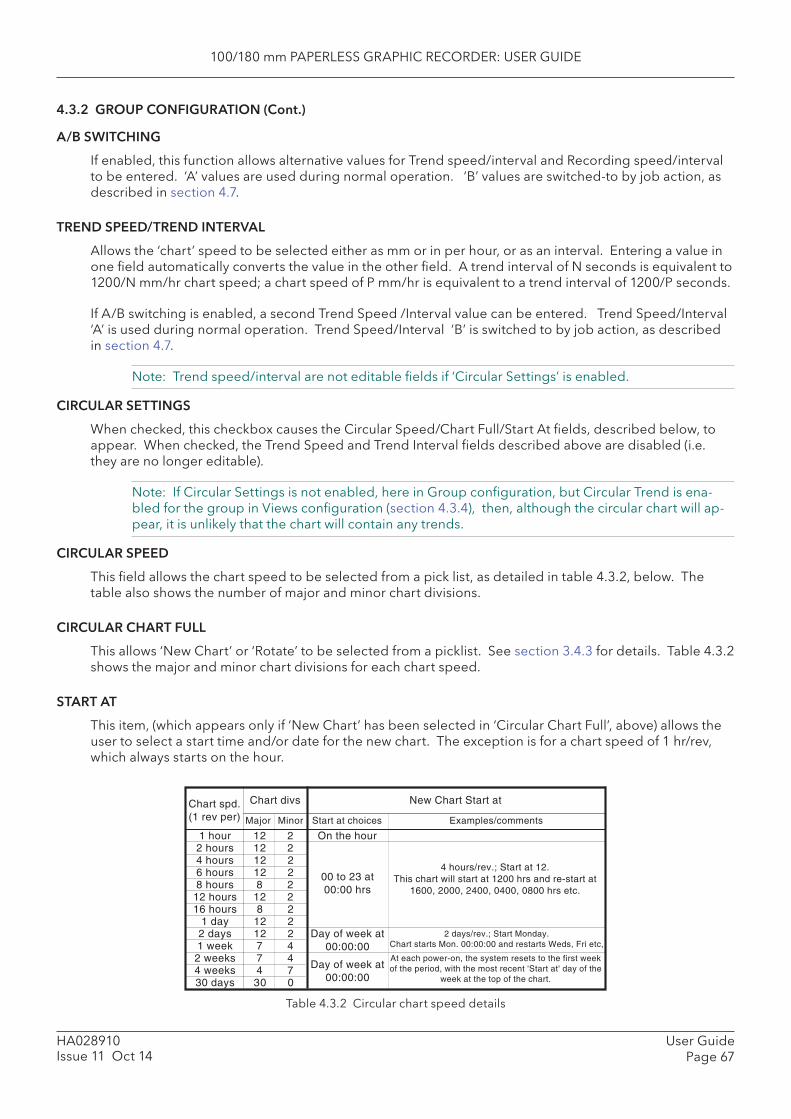
100/180 mm PAPERLESS GRAPHIC RECORDER: USER GUIDE
User GuidePage 67
HA028910Issue 11 Oct 14
4.3.2 GROUP CONFIGURATION (Cont.)
A/B SWITCHING
If enabled, this function allows alternative values for Trend speed/interval and Recording speed/interval to be entered. ‘A’ values are used during normal operation. ‘B’ values are switched-to by job action, as described in section 4.7.
TREND SPEED/TREND INTERVAL
Allows the ‘chart’ speed to be selected either as mm or in per hour, or as an interval. Entering a value in one fi eld automatically converts the value in the other fi eld. A trend interval of N seconds is equivalent to 1200/N mm/hr chart speed; a chart speed of P mm/hr is equivalent to a trend interval of 1200/P seconds.
If A/B switching is enabled, a second Trend Speed /Interval value can be entered. Trend Speed/Interval ‘A’ is used during normal operation. Trend Speed/Interval ‘B’ is switched to by job action, as described in section 4.7.
Note: Trend speed/interval are not editable fi elds if ‘Circular Settings’ is enabled.
CIRCULAR SETTINGS
When checked, this checkbox causes the Circular Speed/Chart Full/Start At fi elds, described below, to appear. When checked, the Trend Speed and Trend Interval fi elds described above are disabled (i.e. they are no longer editable).
Note: If Circular Settings is not enabled, here in Group confi guration, but Circular Trend is ena-bled for the group in Views confi guration (section 4.3.4), then, although the circular chart will ap-pear, it is unlikely that the chart will contain any trends.
CIRCULAR SPEED
This fi eld allows the chart speed to be selected from a pick list, as detailed in table 4.3.2, below. The table also shows the number of major and minor chart divisions.
CIRCULAR CHART FULL
This allows ‘ New Chart’ or ‘ Rotate’ to be selected from a picklist. See section 3.4.3 for details. Table 4.3.2 shows the major and minor chart divisions for each chart speed.
START AT
This item, (which appears only if ‘New Chart’ has been selected in ‘Circular Chart Full’, above) allows the user to select a start time and/or date for the new chart. The exception is for a chart speed of 1 hr/rev, which always starts on the hour.
Table 4.3.2 Circular chart speed details
Chart spd.(1 rev per)
1 hour2 hours4 hours6 hours8 hours
12 hours16 hours
1 day2 days1 week2 weeks4 weeks30 days
Chart divs
Major Minor
121212128
128
121277430
2222222224470
New Chart Start at
On the hour
Day of week at00:00:00
Day of week at00:00:00
00 to 23 at00:00 hrs
Start at choices Examples/comments
4 hours/rev.; Start at 12.This chart will start at 1200 hrs and re-start at
1600, 2000, 2400, 0400, 0800 hrs etc.
2 days/rev.; Start Monday.Chart starts Mon. 00:00:00 and restarts Weds, Fri etc,
At each power-on, the system resets to the first weekof the period, with the most recent 'Start at' day of the
week at the top of the chart.
100/180 mm PAPERLESS GRAPHIC RECORDER: USER GUIDE
HA028910Issue 11 Oct 14
User GuidePage 68
4.3.2 GROUP CONFIGURATION (Cont.)
GRID TYPE
Grid type allows the chart grid type to be defi ned for the group being confi gured. This is not necessarily related to channel scale (section 4.3.3), unless ‘From point’ is selected, when the grid matches the scale of the selected point.
NONE
No chart grid is traced.
LINEAR
The chart grid is linear, with the major and minor divisions defi ned by the fi elds Grid Divisions - Major and Minor, which appear if ‘Linear’ is selected as grid type. Figure 4.3.2c, below, defi nes major and minor divisions.
LOG
The chart grid is logarithmic, with the number of decades being selected in the ‘Grid Decades’ fi eld which appears if ‘Log’ is selected as Grid Type. Figure 4.3.2c gives an example.
Note: For the small frame recorder, the minor divisions within each decade are shown only for groups with ‘Number of decades’ ≤ 5.
FROM POINT
This allows the chart grid to be aligned with the scale of a particular ‘point’, selected in the ‘from’ fi eld which appears if ‘From Point’ is selected as ‘Grid Type’
Figure 4.3.2c Typical chart grid defi nitions
RECORDING ENABLE
This tick box allows the logging of this group’s data to the fl ash memory to be enabled/disabled. When disabled:
a The recording speed/interval fi elds are not editable, and Trend History duration is set to zero.b Display trends are present on the chart, but are not preserved when changing ‘Views’.c It is not possible to enter trace history if ‘Recording Enable’ is not selected.
Notes1 A blue line is drawn across the chart, when recording is re-enabled to indicate a time change in
the trace.2 If a ‘Recording enable’ job (section 4.7.10) is set to act on a particular group, then the group will
be recorded only whilst the job is active, and only if Recording is enabled for the group.
Five major divisions
Two minor divisions
Nine major divisions
Three minor divisions
Three decades
Linear scale
Linear scale
Log scale

100/180 mm PAPERLESS GRAPHIC RECORDER: USER GUIDE
User GuidePage 69
HA028910Issue 11 Oct 14
4.3.2 GROUP CONFIGURATION (Cont.)
RECORDING SPEED/RECORDING INTERVAL
If recording is enabled, these fi elds are as for trend speed/interval but defi ne the rate at which data is saved to Flash memory. This value also affects how much trace history appears per screen in trend his-tory mode (section 3.4). If recording is not enabled, these fi elds are ‘greyed’ and not editable.
If A/B switching is enabled, a second Recording Speed /Interval value can be entered. Recording Speed/Interval ‘A’ is used during normal operation. Recording Speed/Interval ‘B’ is switched to by job action, as described in section 4.7.
Note: With large numbers of points confi gured in one or more groups, the total amount of data generated per iteration may exceed the amount that can be written to the internal FLASH memory in the time available. Such a situation may also arise if many messages are being generated. The recorder responds by reducing the recording speed, and a message ‘Recording failed - internal overfl ow. Slowing recording interval of fastest group(s)’ appears, to draw the user’s attention to the situation.
TREND HISTORY DURATION
Gives an estimated time to fi ll the group’s trend history area of the Flash memory. The calculation is based on the archive rate, the compression ratio, the fl ash size and on the exact nature of the data. (Rap-idly changing values use more space than static/slowly changing values.) If A/B switching is enabled the calculation is based on Recording Speed/Interval ‘A’.
Changing the contents of one group may affect the Trend History Duration of other groups. This hap-pens because the recorder attempts to store, as nearly as possible, the same amount of history for all groups, regardless of how many points there are in the groups.
For ‘empty’ groups, or if Recording is not enabled for a group, the Trend History Duration is displayed as ‘0’ Days.
ARCHIVE TO MEDIA ENABLE/ARCHIVE VIA FTP ENABLE
If recording is enabled, these tick boxes allow the archiving of this group’s data to removable mass stor-age media and/or to a remote host (FTP) to be enabled or disabled. If recording is disabled, these fi elds cannot be edited.
Note: When recording to fl oppy disk drives (via a USB port), it is recommended that only one group be set up with ‘Archive to media’ enabled. This is because history fi les are typically 400kB in size and this limits the number of fi les which can be saved to a 1.4MB fl oppy disk, to three. If more than one group is set up to archive, and if ‘Overwrite’ strategy is selected, then it is likely that all the data for one or more of the groups will be lost. No warning is given.
ALARM MESSAGE
This box allows the printing of alarm on and off messages on the ‘chart’ to be enabled or disabled as re-quired. Alarm messages appear on the trend display and in PC Review in the form HH:MM:SS Alarm ON n/m and HH:MM:SS Alarm OFF n/m, where ‘n’ is the relevant channel number and ‘m’ is the alarm number (1 or 2).
ACK MESSAGE
This tick box allows the printing of alarm acknowledgement messages on the ‘chart’ to be enabled or disabled as required. Acknowledge messages appear on the trend display and in PC Review in the form HH:MM:SS.
ALARM ACKNOWLEDGE
Alarms are acknowledged as described in section 3.1.4.
100/180 mm PAPERLESS GRAPHIC RECORDER: USER GUIDE
HA028910Issue 11 Oct 14
User GuidePage 70
4.3.2 GROUP CONFIGURATION (Cont.)
POINT TYPE/SELECTION
The ‘Point Type’ box, together with the ‘Selection’ box immediately below, offers a quick way of editing the contents of a group, as follows:
1. Select the type of point (Channel, Maths, Totaliser or Counter) to be edited from the Point Type drop down menu.
2. Enter the numbers of all the points of the selected type to be added or deleted, in the ‘Selection’ box. See notes below for further details.
3. Click on ‘Enable’ to add the selected points to the group contents, or on ‘Disable’ to remove them.4. Repeat for other point types, as required.
Notes:1. The status of all points not included in the selection box, remains unchanged.2. Point numbers are entered individually, or as one or more ranges, separated by commas (if ap-
plicable). For example, an entry of ‘1-3,6,9-11’ would cause points 1, 2, 3, 6, 9, 10 and 11 to be added or removed from the group contents. Only numeric characters, commas and hyphens (minus signs) are accepted. If any other character (including space(s)) is included in the list, the edit will fail, with a message ‘ Invalid Selection’ appearing when the ‘Enable’ or ‘Disable’ key is operated..
3. Ranges must be complete: ‘1-’ is not acceptable.4. Each group may contain any or all points, but for vertical and horizontal trend modes, only the
fi rst 36 are displayed, and for circular trend mode, only the fi rst twelve are traced..5. If a point number is entered which is greater than the number of that point type fi tted, then the
selection is ignored. For example, if totalisers 1-60 are selected for deletion, and only 12 are enabled, then the range will be accepted, and totalisers 1 to 12 deleted from the group’s con-tents.
Alternatively, a group’s contents can be edited using the tick-boxes, to include the ticked items in, or to exclude non-ticked items from, the group, as required.
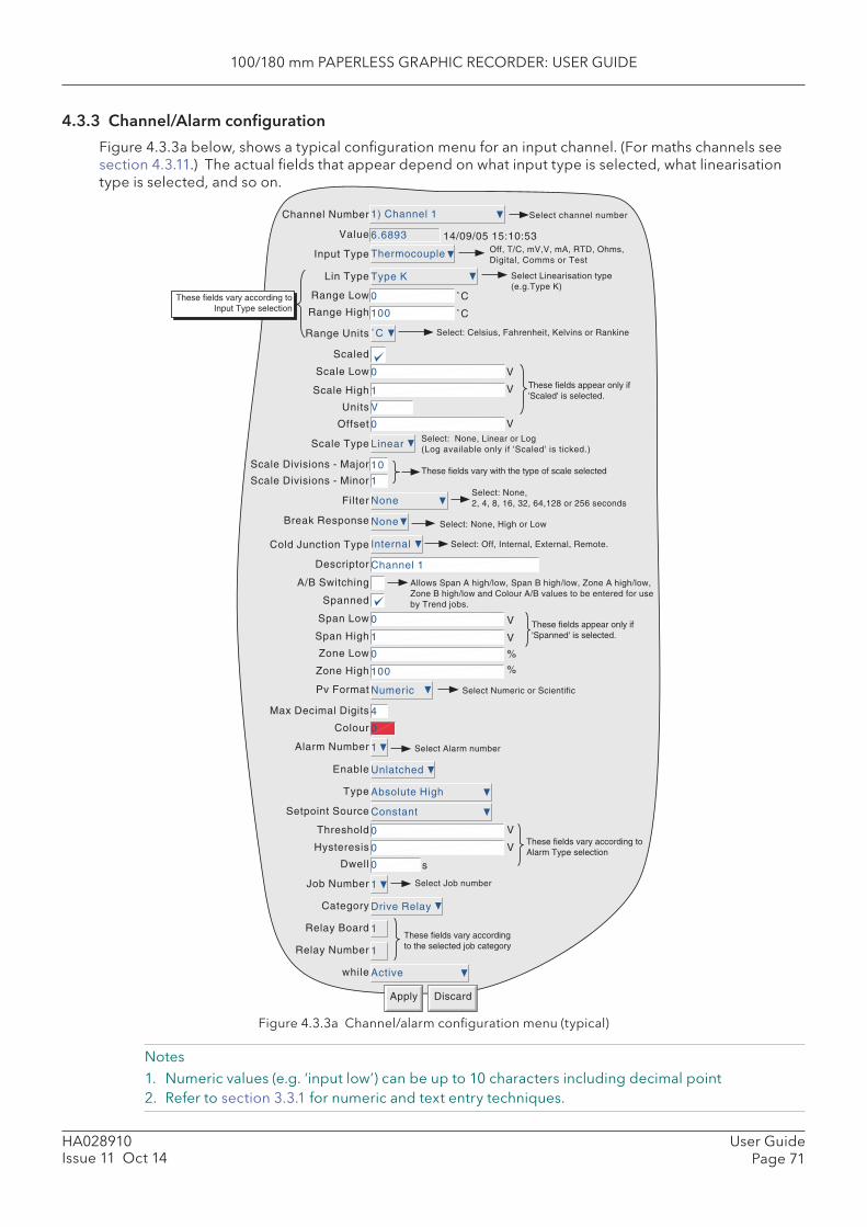
100/180 mm PAPERLESS GRAPHIC RECORDER: USER GUIDE
User GuidePage 71
HA028910Issue 11 Oct 14
4.3.3 Channel/Alarm confi guration
Figure 4.3.3a below, shows a typical confi guration menu for an input channel. (For maths channels see section 4.3.11.) The actual fi elds that appear depend on what input type is selected, what linearisation type is selected, and so on.
Figure 4.3.3a Channel/alarm confi guration menu (typical)
Notes 1. Numeric values (e.g. ‘input low’) can be up to 10 characters including decimal point2. Refer to section 3.3.1 for numeric and text entry techniques.
Apply Discard
Select Linearisation type(e.g.Type K)
Select: Off, Internal, External, Remote.
Select channel number
V
1
0
˚C
100
0
Type K
Thermocouple
6.6893
1) Channel 1
0
Linear
10
1
NoneFilter
None
Internal
Channel 1
0Span Low
1Span High
0Zone Low
100Zone High
NumericPv Format
4Max Decimal Digits
0Colour
1Alarm Number
UnlatchedEnable
Absolute HighType
0Threshold
0Hysteresis
0Dwell
1Job Number
Drive RelayCategory
1Relay Board
1Relay Number
Activewhile
Channel Number
Value
Input Type
Lin Type
Range Low
Range High
Range Units
Scaled
Scale Low
Scale High
Units
Offset
Scale Type
Scale Divisions - Major
Scale Divisions - Minor
Break Response
Cold Junction Type
Descriptor
Spanned
14/09/05 15:10:53
˚C
˚C
V
V
V
Off, T/C, mV,V, mA, RTD, Ohms,Digital, Comms or Test
Select: Celsius, Fahrenheit, Kelvins or Rankine
Select: None, Linear or Log(Log available only if 'Scaled' is ticked.)
Select: None, High or Low
Select: None,2, 4, 8, 16, 32, 64,128 or 256 seconds
Select Alarm number
V
V
%
%
V
V
s
These fields vary accordingto the selected job category
These fields appear only if'Spanned' is selected.
These fields vary according toAlarm Type selection
These fields appear only if'Scaled' is selected.
These fields vary with the type of scale selected
A/B Switching
Select Job number
These fields vary according toInput Type selection
Allows Span A high/low, Span B high/low, Zone A high/low,Zone B high/low and Colour A/B values to be entered for useby Trend jobs.
Select Numeric or Scientific
ConstantSetpoint Source
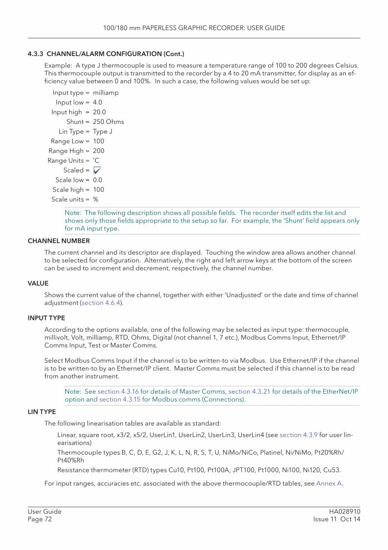
100/180 mm PAPERLESS GRAPHIC RECORDER: USER GUIDE
HA028910Issue 11 Oct 14
User GuidePage 72
4.3.3 CHANNEL/ALARM CONFIGURATION (Cont.)
Example: A type J thermocouple is used to measure a temperature range of 100 to 200 degrees Celsius. This thermocouple output is transmitted to the recorder by a 4 to 20 mA transmitter, for display as an ef-fi ciency value between 0 and 100%. In such a case, the following values would be set up:
Input type = milliamp Input low = 4.0 Input high = 20.0 Shunt = 250 Ohms Lin Type = Type J Range Low = 100 Range High = 200 Range Units = ˚C Scaled = Scale low = 0.0 Scale high = 100 Scale units = %
Note: The following description shows all possible fi elds. The recorder itself edits the list and shows only those fi elds appropriate to the setup so far. For example, the ‘Shunt’ fi eld appears only for mA input type.
CHANNEL NUMBER
The current channel and its descriptor are displayed. Touching the window area allows another channel to be selected for confi guration. Alternatively, the right and left arrow keys at the bottom of the screen can be used to increment and decrement, respectively, the channel number.
VALUE
Shows the current value of the channel, together with either ‘Unadjusted’ or the date and time of channel adjustment (section 4.6.4).
INPUT TYPE
According to the options available, one of the following may be selected as input type: thermocouple, millivolt, Volt, milliamp, RTD, Ohms, Digital (not channel 1, 7 etc.), Modbus Comms Input, Ethernet/IP Comms Input, Test or Master Comms.
Select Modbus Comms Input if the channel is to be written-to via Modbus. Use Ethernet/IP if the channel is to be written-to by an Ethernet/IP client. Master Comms must be selected if this channel is to be read from another instrument.
Note: See section 4.3.16 for details of Master Comms, section 4.3.21 for details of the EtherNet/IP option and section 4.3.15 for Modbus comms (Connections).
LIN TYPE
The following linearisation tables are available as standard:
Linear, square root, x3/2, x5/2, UserLin1, UserLin2, UserLin3, UserLin4 (see section 4.3.9 for user lin-earisations)
Thermocouple types B, C, D, E, G2, J, K, L, N, R, S, T, U, NiMo/NiCo, Platinel, Ni/NiMo, Pt20%Rh/Pt40%Rh
Resistance thermometer (RTD) types Cu10, Pt100, Pt100A, JPT100, Pt1000, Ni100, Ni120, Cu53.
For input ranges, accuracies etc. associated with the above thermocouple/RTD tables, see Annex A.
100/180 mm PAPERLESS GRAPHIC RECORDER: USER GUIDE
User GuidePage 73
HA028910Issue 11 Oct 14
4.3.3 CHANNEL/ALARM CONFIGURATION (Cont.)
INPUT LOW
Enter the lowest value to be applied to the input terminals (e.g. 4.00).
INPUT HIGH
Enter the highest value to be applied across the input terminals (e.g. 20.00).
SHUNT
Allows a shunt resistor value to be entered for input type = mA. Commonly used values are 100 ohms and 250 ohms. Note that shunt resistors are connected to the input connector. The recorder cannot detect whether a shunt is fi tted, or if one is, what value it has. Therefore it is the responsibility of the user to ensure that the ohmic value of any shunt fi tted matches the shunt value entered in this fi eld.
RANGE LOW
Enter the lowest value of the required linearisation range (e.g. 100)
RANGE HIGH
Enter the highest value of the required linearisation range (e.g. 200)
RANGE UNITS
Selectable from degrees Celsius, degrees Fahrenheit, Kelvin or Rankine.
SCALED
This box allows the user to select low and high values and units for a scale. This box must be ticked if logarithmic scales are to be used.
SCALE LOW
Enter the scale value to correspond with input range low (e.g. 0).
SCALE HIGH
Enter the scale value to correspond with input range high (e.g. 100).
SCALE UNITS
Enter up to fi ve characters of unit descriptor (e.g.%).
Note: User linearisation tables units, To set user linearisation table units to temperature units (˚C for example), the Range Units selec-
tion box can be used. To enter custom units, ‘Scaled’ must be selected. Scale low must be set to Range Low; Scale
high must be set to Range High. The required Units string is entered in the Scale units text entry box.
OFFSET
Allows a fi xed value to be added to or subtracted from the process variable. Recorder accuracy fi gures no longer apply if an offset is included.
If the TUS option is fi tted (section 15), Offset can not be applied to channels used as reference channels (e.g. channels 6, 12, 18 etc.).
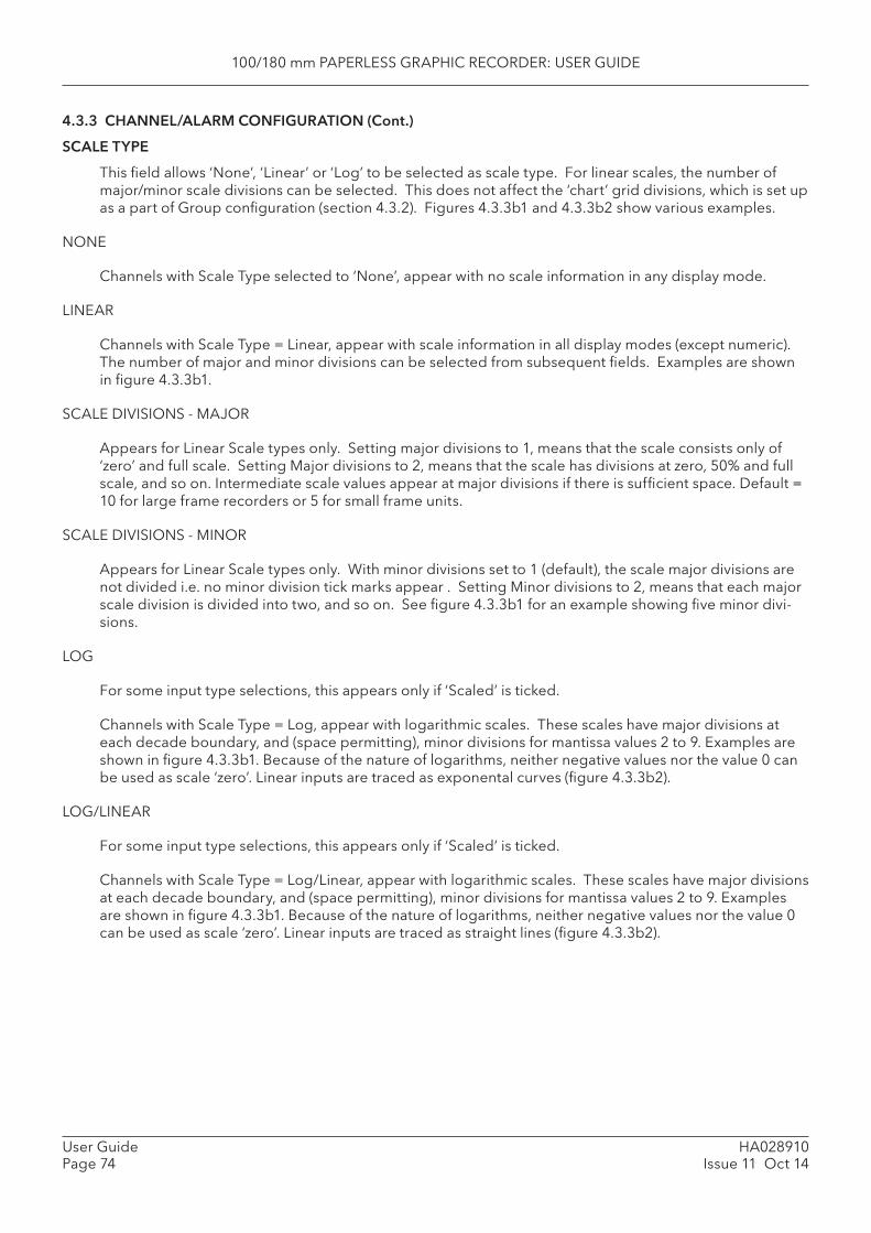
100/180 mm PAPERLESS GRAPHIC RECORDER: USER GUIDE
HA028910Issue 11 Oct 14
User GuidePage 74
4.3.3 CHANNEL/ALARM CONFIGURATION (Cont.)
SCALE TYPE
This fi eld allows ‘None’, ‘Linear’ or ‘Log’ to be selected as scale type. For linear scales, the number of major/minor scale divisions can be selected. This does not affect the ‘chart’ grid divisions, which is set up as a part of Group confi guration (section 4.3.2). Figures 4.3.3b1 and 4.3.3b2 show various examples.
NONE
Channels with Scale Type selected to ‘None’, appear with no scale information in any display mode.
LINEAR
Channels with Scale Type = Linear, appear with scale information in all display modes (except numeric). The number of major and minor divisions can be selected from subsequent fi elds. Examples are shown in fi gure 4.3.3b1.
SCALE DIVISIONS - MAJOR
Appears for Linear Scale types only. Setting major divisions to 1, means that the scale consists only of ‘zero’ and full scale. Setting Major divisions to 2, means that the scale has divisions at zero, 50% and full scale, and so on. Intermediate scale values appear at major divisions if there is suffi cient space. Default = 10 for large frame recorders or 5 for small frame units.
SCALE DIVISIONS - MINOR
Appears for Linear Scale types only. With minor divisions set to 1 (default), the scale major divisions are not divided i.e. no minor division tick marks appear . Setting Minor divisions to 2, means that each major scale division is divided into two, and so on. See fi gure 4.3.3b1 for an example showing fi ve minor divi-sions.
LOG
For some input type selections, this appears only if ‘Scaled’ is ticked.
Channels with Scale Type = Log, appear with logarithmic scales. These scales have major divisions at each decade boundary, and (space permitting), minor divisions for mantissa values 2 to 9. Examples are shown in fi gure 4.3.3b1. Because of the nature of logarithms, neither negative values nor the value 0 can be used as scale ‘zero’. Linear inputs are traced as exponental curves (fi gure 4.3.3b2).
LOG/LINEAR
For some input type selections, this appears only if ‘Scaled’ is ticked.
Channels with Scale Type = Log/Linear, appear with logarithmic scales. These scales have major divisions at each decade boundary, and (space permitting), minor divisions for mantissa values 2 to 9. Examples are shown in fi gure 4.3.3b1. Because of the nature of logarithms, neither negative values nor the value 0 can be used as scale ‘zero’. Linear inputs are traced as straight lines (fi gure 4.3.3b2).
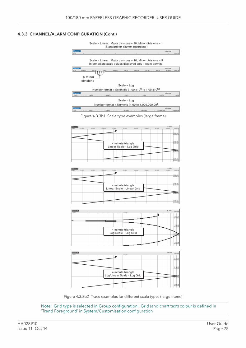
100/180 mm PAPERLESS GRAPHIC RECORDER: USER GUIDE
User GuidePage 75
HA028910Issue 11 Oct 14
4.3.3 CHANNEL/ALARM CONFIGURATION (Cont.)
Figure 4.3.3b1 Scale type examples (large frame)
Figure 4.3.3b2 Trace examples for different scale types (large frame)
Note: Grid type is selected in Group confi guration. Grid (and chart text) colour is defi ned in ‘Trend Foreground’ in System/Customisation confi guration
1000.000.00
Channel 2 388.33V
5 minordivisions
Scale = Linear: Major divisions = 10; Minor divisions = 1(Standard for 180mm recorders )
Scale = Linear: Major divisions = 10; Minor divisions = 5Intermediate scale values displayed only if room permits.
1.00E61.00E0
Channel 2 388.33V
Scale = Log
Number format = Scientific (1.00 x100 to 1.00 x10⁶)
1.00E51.00E41.00E31.00E21.00E1
1000000.001.00
Channel 2 388.33V
Scale = Log
Number format = Numeric (1.00 to 1,000,000.00)
100000.0010000.001000.00100.0010.00
200.00 300.00 400.00 500.00 600.00 700.00 800.00 900.00 1000.00100.000.00
Channel 2 388.33V
10:49:1825/05/06
10:47:5825/05/06
10:46:3825/05/06
10:45:1825/05/06
0.0000
Channel 4710.0000 20.0000 30.0000 40.0000 50.0000 60.0000 70.0000 80.0000 90.0000 100.0000
41.6667V
4 minute triangleLinear Scale - Linear Grid
11:57:2125/05/06
11:56:0025/05/06
11:54:4025/05/06
11:53:2025/05/06
1.0000Channel 47
10.0000100.0000
41.4250V
4 minute triangleLog Scale - Log Grid
12:13:2125/05/06
12:12:0025/05/06
12:09:2025/05/06
12:10:4025/05/06
1.0000Channel 47
10.0000100.0000
6.4158V
10:44:1825/05/06
10:42:5825/05/06
10:41:3825/05/06
10:40:1825/05/06
0.0000
Channel 4710.0000 20.0000 30.0000 40.0000 50.0000 60.0000 70.0000 80.0000 90.0000 100.0000
41.6667V
4 minute triangleLinear Scale - Log Grid
4 minute triangleLog/Linear Scale - Log Grid
4 minute triangleLog/Linear Scale - Log Grid
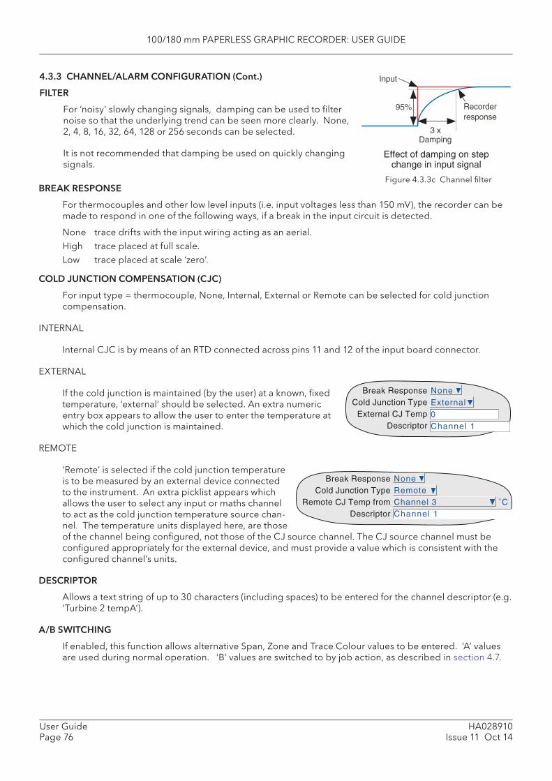
100/180 mm PAPERLESS GRAPHIC RECORDER: USER GUIDE
HA028910Issue 11 Oct 14
User GuidePage 76
BREAK RESPONSE
For thermocouples and other low level inputs (i.e. input voltages less than 150 mV), the recorder can be made to respond in one of the following ways, if a break in the input circuit is detected.
None trace drifts with the input wiring acting as an aerial.High trace placed at full scale.Low trace placed at scale ‘zero’.
COLD JUNCTION COMPENSATION ( CJC)
For input type = thermocouple, None, Internal, External or Remote can be selected for cold junction compensation.
INTERNAL
Internal CJC is by means of an RTD connected across pins 11 and 12 of the input board connector.
EXTERNAL
If the cold junction is maintained (by the user) at a known, fi xed temperature, ‘external’ should be selected. An extra numeric entry box appears to allow the user to enter the temperature at which the cold junction is maintained.
REMOTE
‘Remote’ is selected if the cold junction temperature is to be measured by an external device connected to the instrument. An extra picklist appears which allows the user to select any input or maths channel to act as the cold junction temperature source chan-nel. The temperature units displayed here, are those of the channel being confi gured, not those of the CJ source channel. The CJ source channel must be confi gured appropriately for the external device, and must provide a value which is consistent with the confi gured channel’s units.
DESCRIPTOR
Allows a text string of up to 30 characters (including spaces) to be entered for the channel descriptor (e.g. ‘Turbine 2 tempA’).
A/B SWITCHING
If enabled, this function allows alternative Span, Zone and Trace Colour values to be entered. ‘A’ values are used during normal operation. ‘B’ values are switched to by job action, as described in section 4.7.
4.3.3 CHANNEL/ALARM CONFIGURATION (Cont.)
FILTER
For ‘noisy’ slowly changing signals, damping can be used to fi lter noise so that the underlying trend can be seen more clearly. None, 2, 4, 8, 16, 32, 64, 128 or 256 seconds can be selected.
It is not recommended that damping be used on quickly changing signals.
Input
95%
3 xDamping
Recorderresponse
Effect of damping on stepchange in input signal
Break ResponseCold Junction Type
External CJ TempDescriptor
NoneExternal0Channel 1
Figure 4.3.3c Channel fi lter
Break ResponseCold Junction Type
Remote CJ Temp fromDescriptor
NoneRemoteChannel 3 ˚CChannel 1
100/180 mm PAPERLESS GRAPHIC RECORDER: USER GUIDE
User GuidePage 77
HA028910Issue 11 Oct 14
4.3.3 CHANNEL/ALARM CONFIGURATION (Cont.)
SPANNED
This box, when selected, allows span low and high values to be entered. For example, in an input range of 0 to 600 deg C, it may be that the temperature range between 500 and 600 degrees is of most inter-est. In such a case, setting span low to 500 and span high to 600 will cause the recorder to display only that part of the input range, and this will fi ll the zone width which is selected next, effectively magnifying the area of interest.
If A/B switching is enabled, a second set of span low and span high values can be entered. ‘A’ values are used during normal operation. ‘B’ values are switched to by job action, as described in section 4.7.
ZONE
This allows the portion of the chart which the channel occupies to be defi ned in terms of percent, where the left edge of the chart is 0% and the right hand edge is 100%. For example, setting a low value of 50 and a high value of 100 causes the channel trace to be confi ned to the right hand half of the chart.
If A/B switching is enabled, a second set of zone low and zone high values can be entered. ‘A’ values are used during normal operation. ‘B’ values are switched to by job action, as described in section 4.7.
PV FORMAT
This allows the PV value, alarm setpoints, hysteresis values etc. to be displayed as normal numeric val-ues ( Numeric) or in ‘ Scientifi c’ format (Scientifi c). When ‘Scientifi c’ is selected, values are displayed and entered as a decimal number between 1 and 10† (the mantissa), followed by a multiplier (the exponent). E.G. to enter a value of 1244.5678, the value entered would be 1.2445678E3, where 3 represents the number of places that the decimal point has been shifted to the left in order to convert the value to a number between 1 and 10†. To enter a value of 0.0004196, the entry would be 4.196E-4.
† Notes 1. Strictly this is a number less than 10, as 10 would be 1.0E1.2. There must be at least one number after the decimal point.
MAXIMUM DECIMAL DIGITS
This defi nes the number of decimal places in the process value. Settable between zero and nine. Lead-ing and trailing zeros are not displayed. Values too long for the available displaying width are truncated as described in section 3.
COLOUR
Allows the trace colour to be selected from a colour chart. Each of the 56 available colours is displayed with a number, and it is this number which is entered. The background colour to the selection box chang-es to the selected colour.
If A/B switching is enabled, a second colour selection can be entered. Colour ‘A’ is used during normal operation. Colour ‘B’ is switched to by job action, as described in section 4.7.
ALARM NUMBER
Allows an alarm to be selected for confi guration.
100/180 mm PAPERLESS GRAPHIC RECORDER: USER GUIDE
HA028910Issue 11 Oct 14
User GuidePage 78
4.3.3 CHANNEL/ALARM CONFIGURATION (Cont.)
ENABLE
Allows the alarm to be defi ned as Off, Unlatched, Latched or Trigger.
Off Alarm is disabled and the remainder of the alarm confi guration is hidden. Unlatched Unlatched alarms become active when the trigger source becomes active and re-
main active until the source returns to a non-active state. The indicator is on (fl ashing before acknowledgment - steady after acknowledge-
ment) until the alarm clears. Alarm messages are printed if enabled in group confi guration. Latched Latched alarms become active when the trigger source becomes active and remain
active until the alarm is acknowledged AND the trigger source has returned to a non-active state.
The indicator is on (fl ashing before acknowledgment - steady after acknowledge-ment) until the alarm has been acknowledged AND the trigger source has returned to a non-active state.
Alarm messages are printed if enabled in group confi guration. Continuous jobs remain active only whilst the alarm trigger source is active. I.E. the
job fi nishes when the alarm clears, whether acknowledged or not. Trigger When triggered all associated jobs are initiated, and continuous jobs remain active
until the alarm clears. There is no alarm indication, and no messages are printed.
TYPE
This fi eld appears only when the alarm Enable is not selected Off. Each alarm can be defi ned as absolute high, absolute low, deviation-in, deviation-out, rate-of-change rise or rate-of-change fall.
Absolute High As shown in fi gure 4.3.3d, an absolute high alarm becomes active when the channel value exceeds the threshold value. The alarm remains active until the channel value falls below (Threshold minus hysteresis). If a dwell value is defi ned, the alarm does not become effective until this dwell time has been exceeded.
Absolute Low As shown in fi gure 4.3.3d, an absolute low alarm becomes active when the chan-nel value falls below the threshold value. The alarm remains active until the channel value exceeds (Threshold + hysteresis). If a dwell value is defi ned, the alarm does not become effective until this dwell time has been exceeded.
Deviation in As shown in fi gure 4.3.3e, a deviation-in alarm becomes active whenever the chan-nel value enters the band: Reference ± Deviation. It remains active until the channel value leaves the band: Reference ± (Deviation+ Hysteresis). If a dwell value is de-fi ned, the alarm does not become effective until this dwell time has been exceeded.
Deviation out As shown in fi gure 4.3.3e, a deviation-out alarm is active whenever the channel value leaves the band Reference ± Deviation. It remains active until the channel value enters the band: Reference ± (Deviation - Hysteresis). If a dwell value is defi ned, the alarm does not become effective until this dwell time has been exceeded.
Rate of change As shown in fi gure 4.3.3f, rate of change alarms become active whenever the signal value changes by more than a specifi ed amount within a specifi ed period. If a dwell value is defi ned, the alarm does not become effective until this dwell time has been exceeded. An averaging period can be set to remove the effects of sudden, but short-lived changes, such as noise spikes on the signal.
Note: Alarm icons appear at the display, as described in section 3.
SETPOINT SOURCE
Allows the user to choose either a fi xed, user-defi ned value (constant) or the value of another point (input channel, maths channel, totaliser etc.) to be chosen as the trigger point. In the latter it is possible, for example, to trigger an alarm, when one channel’s value rises above, falls below etc. the value of a second channel.
100/180 mm PAPERLESS GRAPHIC RECORDER: USER GUIDE
User GuidePage 79
HA028910Issue 11 Oct 14
4.3.3 CHANNEL/ALARM CONFIGURATION (Cont.)
PARAMETERS
Figures 4.3.3d, e and f illustrate the following terms for the different alarm types.
Threshold For Absolute alarms, this defi nes the value (in engineering units) at which an alarm is triggered. The alarm also returns to its non-active state at this value (unless a hys-teresis value has been set). If a dwell value is set, the alarm does not become active until this dwell time has elapsed.
Hysteresis Defi nes a ‘deadband’ (in engineering units) to eliminate spurious triggering if the signal value is hovering around the trigger point. The deadband lies:
Below Absolute High thresholds Above Absolute Low thresholds Outside the deviation band for Deviation-in alarms Inside the deviation band for Deviation-out alarms. Dwell Allows a dwell period to be entered in seconds. The alarm does not take effect until
this period has expired. If an alarm clears before the dwell period has expired, the alarm is ignored.
Reference For Deviation alarms, this is the central value of the deviation band. Deviation For Deviation alarms, this value defi nes the width of the deviation band, each side of
the reference value. I.E. the total width of the deviation band is 2 x Deviation value. Amount For Rate-of-change alarms, this value defi nes the minimum amount by which the
signal value would have to change, within the ‘Change Time’ period (below), in order for the alarm to become active.
Change Time For Rate-of-change alarms, this selects the time period (Per second, Per minute, Per hour) within which the change in signal value must exceed the Amount value (entered in the preceding fi eld) in order for the alarm to become active. See Rate-of-Change example below for more details.
Average time For rate-of-change alarms, this allows an average period to be entered for signal smoothing.
HYSTERESIS EXAMPLE
Threshold = 100 units; Hysteresis = 5 units
With the above settings, an absolute high alarm would become active if its input were to rise above 100 and would remain active until its value fell to below 95 units. An absolute low alarm would become active if its input fell below 100 units, and would remain active until its input rose above 105 units. Deviation alarms behave in a similar manner.
RATE-OF CHANGE ALARM EXAMPLE
Rate-of-change alarms allow the user to enter an ‘amount’ (say 3 degrees) and a time period (say 1 minute) , and if the process value changes by the specifi ed amount or more, within the specifi ed time period (more than 3 degrees in a minute in this example), then the alarm becomes active.
The recorder uses its iteration rate of 125 msec (1/8th second) as the time base for it calculations. For our example, 3 degrees per minute equates to 3/60 degrees per second or 3/(60 x 8) = 0.00625 degrees per iteration. If a change greater than this is detected, then the alarm becomes active.
In order to reduce sensitivity, an averaging period can be confi gured. This means that an average of all the 1/8th second samples is taken over the specifi ed period, and the alarm becomes active only if the average value exceeds the specifi ed rate of change.
Confi guring a dwell time can also reduce ‘jitter’ because, if during the specifi ed dwell time, any one sam-ple is non active, then the elapsed dwell time is reset to zero. The alarm becomes active only after the dwell time has elapsed i.e. only if the rate of change has been exceeded for every software cycle through-out the specifi ed dwell time.
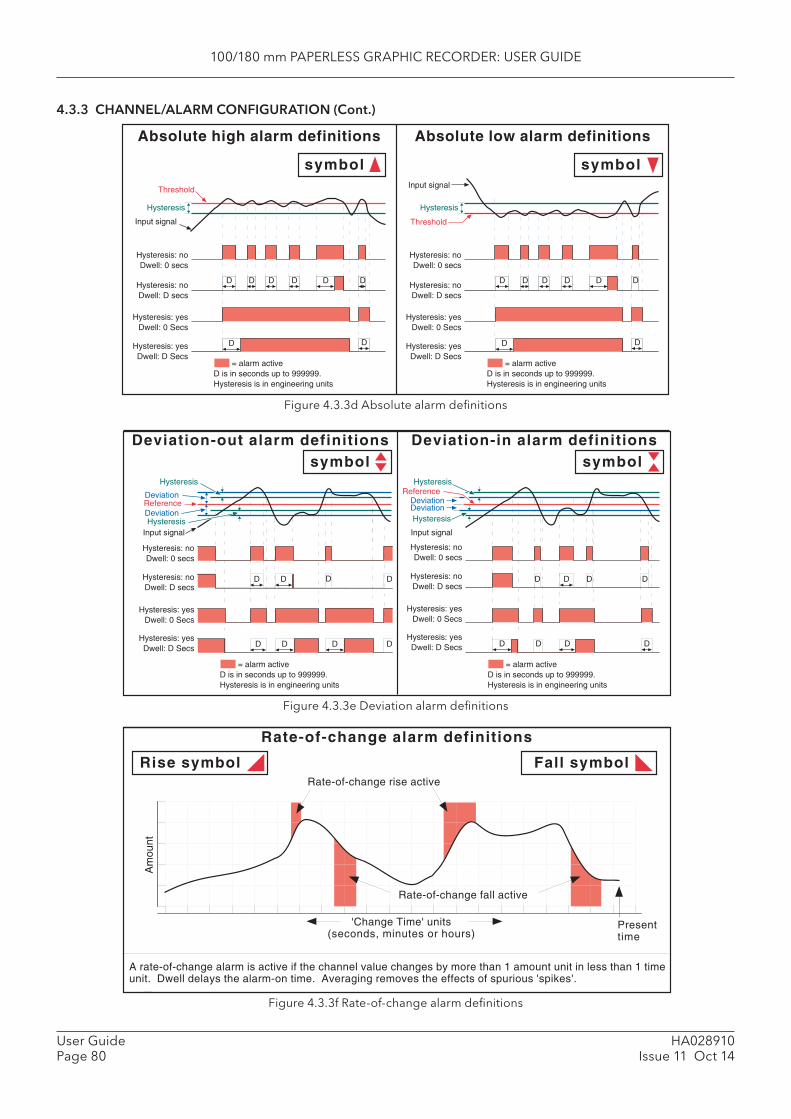
100/180 mm PAPERLESS GRAPHIC RECORDER: USER GUIDE
HA028910Issue 11 Oct 14
User GuidePage 80
4.3.3 CHANNEL/ALARM CONFIGURATION (Cont.)
Figure 4.3.3d Absolute alarm defi nitions
Figure 4.3.3e Deviation alarm defi nitions
Figure 4.3.3f Rate-of-change alarm defi nitions
Threshold
Hysteresis
Hysteresis: noDwell: 0 secs
= alarm activeD is in seconds up to 999999.Hysteresis is in engineering units
Hysteresis: noDwell: D secs
Hysteresis: yesDwell: 0 Secs
Hysteresis: yesDwell: D Secs
Input signal
Absolute low alarm definitionsAbsolute high alarm definitions
D
Threshold
Hysteresis
Hysteresis: noDwell: 0 secs
= alarm activeD is in seconds up to 999999.Hysteresis is in engineering units
Hysteresis: noDwell: D secs
Hysteresis: yesDwell: 0 Secs
Hysteresis: yesDwell: D Secs
Input signal
symbol symbol
D D D D D
DD
D D D D D D
DD
Am
ount
'Change Time' units(seconds, minutes or hours)
Rate-of-change alarm definitions
Rise symbol Fall symbol
Presenttime
A rate-of-change alarm is active if the channel value changes by more than 1 amount unit in less than 1 timeunit. Dwell delays the alarm-on time. Averaging removes the effects of spurious 'spikes'.
Rate-of-change rise active
Rate-of-change fall active
ReferenceDeviation
Hysteresis: noDwell: 0 secs
= alarm activeD is in seconds up to 999999.Hysteresis is in engineering units
Hysteresis: noDwell: D secs
Hysteresis: yesDwell: 0 Secs
Hysteresis: yesDwell: D Secs
Input signal
Deviation-in alarm definitions
Hysteresis
Deviation-out alarm definitionssymbolsymbol
Reference
Hysteresis
Hysteresis: noDwell: 0 secs
= alarm activeD is in seconds up to 999999.Hysteresis is in engineering units
Hysteresis: noDwell: D secs
Hysteresis: yesDwell: 0 Secs
Hysteresis: yesDwell: D Secs
Input signal
D
Deviation
Deviation
Hysteresis
DeviationHysteresis
D D D
D D D D
DD D D
D D D D
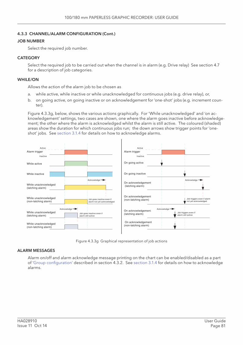
100/180 mm PAPERLESS GRAPHIC RECORDER: USER GUIDE
User GuidePage 81
HA028910Issue 11 Oct 14
4.3.3 CHANNEL/ALARM CONFIGURATION (Cont.)
JOB NUMBER
Select the required job number.
CATEGORY
Select the required job to be carried out when the channel is in alarm (e.g. Drive relay) See section 4.7 for a description of job categories.
WHILE/ON
Allows the action of the alarm job to be chosen as
a. while active, while inactive or while unacknowledged for continuous jobs (e.g. drive relay), or, b. on going active, on going inactive or on acknowledgement for ‘one-shot’ jobs (e.g. increment coun-
ter).
Figure 4.3.3g, below, shows the various actions graphically. For ‘While unacknowledged’ and ‘on ac-knowledgement’ settings, two cases are shown, one where the alarm goes inactive before acknowledge-ment; the other where the alarm is acknowledged whilst the alarm is still active. The coloured (shaded) areas show the duration for which continuous jobs run; the down arrows show trigger points for ‘one-shot’ jobs. See section 3.1.4 for details on how to acknowledge alarms.
Figure 4.3.3g Graphical representation of job actions
ALARM MESSAGES
Alarm on/off and alarm acknowledge message printing on the chart can be enabled/disabled as a part of ‘Group confi guration’ described in section 4.3.2. See section 3.1.4 for details on how to acknowledge alarms.
Alarm triggerActive
Inactive
While active
While inactive
While unacknowledged(latching alarm)
While unacknowledged(non-latching alarm)
While unacknowledged(non-latching alarm)
Job goes inactive even ifalarm not yet acknowledged
While unacknowledged(latching alarm)
Job goes inactive even ifalarm still active
Alarm triggerActive
Inactive
On going active
On going inactive
On acknowledgement (latching alarm)
Acknowledge
On acknowledgement(non-latching alarm)
On acknowledgement(non-latching alarm)
Job triggers even if alarmnot yet acknowledged
On acknowledgement(latching alarm)
Job triggers even ifalarm still active
Acknowledge
Acknowledge
Acknowledge
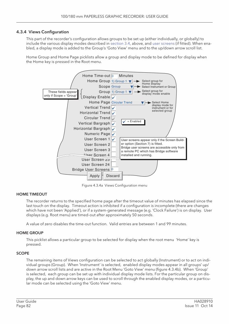
100/180 mm PAPERLESS GRAPHIC RECORDER: USER GUIDE
HA028910Issue 11 Oct 14
User GuidePage 82
4.3.4 Views Confi guration
This part of the recorder’s confi guration allows groups to be set up (either individually, or globally) to include the various display modes described in section 3.4, above, and user screens (if fi tted). When ena-bled, a display mode is added to the Group’s ‘Goto View’ menu and to the up/down arrow scroll list.
Home Group and Home Page picklists allow a group and display mode to be defi ned for display when the Home key is pressed in the Root menu.
Figure 4.3.4a Views Confi guration menu
HOME TIMEOUT
The recorder returns to the specifi ed home page after the timeout value of minutes has elapsed since the last touch on the display. Timeout action is inhibited if a confi guration is incomplete (there are changes which have not been ‘Applied’), or if a system-generated message (e.g. ‘Clock Failure’) is on display. User displays (e.g. Root menu) are timed-out after approximately 50 seconds.
A value of zero disables the time-out function. Valid entries are between 1 and 99 minutes.
HOME GROUP
This picklist allows a particular group to be selected for display when the root menu ‘Home’ key is pressed.
SCOPE
The remaining items of Views confi guration can be selected to act globally (Instrument) or to act on indi-vidual groups (Group). When ‘Instrument’ is selected, enabled display modes appear in all groups’ up/down arrow scroll lists and are active in the Root Menu ‘Goto View’ menu (fi gure 4.3.4b). When ‘Group’ is selected, each group can be set up with individual display mode lists. For the particular group on dis-play, the up and down arrow keys can be used to scroll through the enabled display modes, or a particu-lar mode can be selected using the ‘Goto View’ menu.
Select Homedisplay mode forinstrument or forselected group
= Enabled
Home Time-outHome Group
ScopeGroup
Display EnableHome Page
Vertical TrendHorizontal Trend
Vertical BargraphHorizontal Bargraph
Numeric PageUser Screen 1
User Screen 2User Screen 3User Screen 4
1) Group 1
Apply Discard
0
Group
1) Group 1
Circular Trend
Select group forHome display
Select group fordisplay mode enable
These fields appearonly if Scope = 'Group'
Select Instrument or Group
Minutes
Circular Trend
User Screen 23User Screen 24
Bridge User Screens
User screens appear only if the Screen Build-er option (Section 7) is fitted.Bridge user screens are accessible only froma remote PC which has Bridge softwareinstalled and running.
0

100/180 mm PAPERLESS GRAPHIC RECORDER: USER GUIDE
User GuidePage 83
HA028910Issue 11 Oct 14
4.3.4 VIEWS CONFIGURATION (Cont.)
GROUP
This fi eld appears only if ‘Scope’ is set to ‘Group’, and allows each group to be selected for display con-fi guration. For other items of Group confi guration, see Section 4.3.2.
DISPLAY ENABLE
This fi eld appears only if ‘Scope’ is set to ‘Group’, and allows the selected group to be enabled or disa-bled for display. When enabled, the group can be displayed either by using the ‘Root menu/Goto screens/Group N’ selection (fi gure 4.3.4b) or can be scrolled-to using the right/left arrow keys. When disabled, the group is ‘greyed’ in the ‘Root menu/Goto screens/Group N’ selection and is skipped when using the right/left arrow keys. It is not possible to disable the Home group.
HOME PAGE
Allows a particular display mode to be selected as the default display, either for all groups (Scope = in-strument) or on a group-by-group basis (Scope = group).
DISPLAY MODE ENABLING
A series of tick boxes allow the various display modes to be added to (or removed from) the up/down arrow scroll list and to be activated/deactivated in the Root menu ‘Goto View’ menu, either for all groups (Scope = instrument) or on a group-by-group basis (Scope = group). It is not possible to disable the selected Home page mode.
Note: If Circular Trend view is enabled here in Views confi guration, but the ‘Circular settings’ checkbox is not enabled in Group confi guration (section 4.3.2), then, although the circular chart will appear, it will not contain any trends.
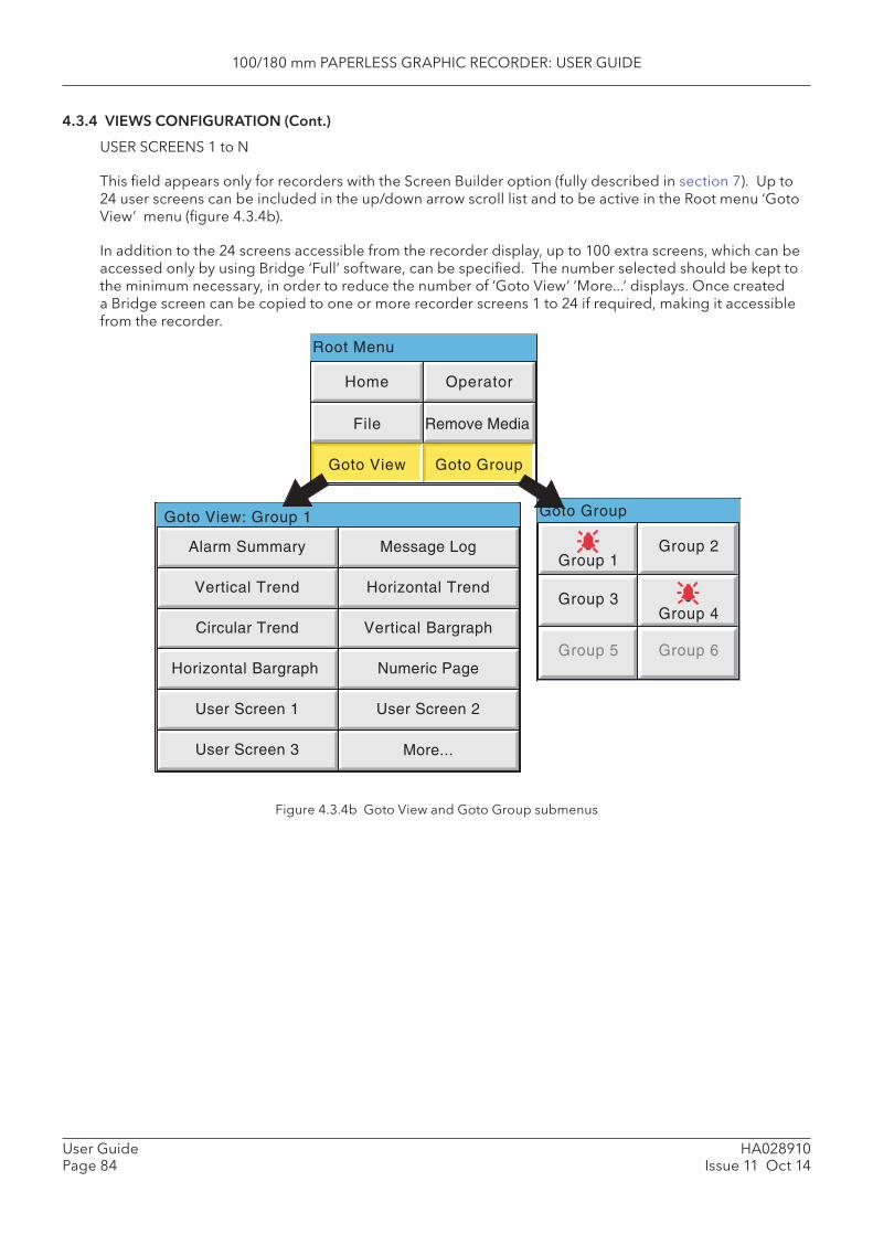
100/180 mm PAPERLESS GRAPHIC RECORDER: USER GUIDE
HA028910Issue 11 Oct 14
User GuidePage 84
4.3.4 VIEWS CONFIGURATION (Cont.)
USER SCREENS 1 to N
This fi eld appears only for recorders with the Screen Builder option (fully described in section 7). Up to 24 user screens can be included in the up/down arrow scroll list and to be active in the Root menu ‘Goto View’ menu (fi gure 4.3.4b).
In addition to the 24 screens accessible from the recorder display, up to 100 extra screens, which can be accessed only by using Bridge ‘Full’ software, can be specifi ed. The number selected should be kept to the minimum necessary, in order to reduce the number of ‘Goto View’ ‘More...’ displays. Once created a Bridge screen can be copied to one or more recorder screens 1 to 24 if required, making it accessible from the recorder.
Figure 4.3.4b Goto View and Goto Group submenus
Root Menu
Goto GroupGoto View: Group 1
Home Operator
File
Goto View Goto Group
Message Log
Horizontal Trend
Vertical Bargraph
Alarm Summary
Vertical Trend
Circular Trend
Numeric Page
User Screen 2
Horizontal Bargraph
User Screen 1
User Screen 3 More...
Group 1Group 2
Group 3Group 4
Group 5 Group 6
Remove Media
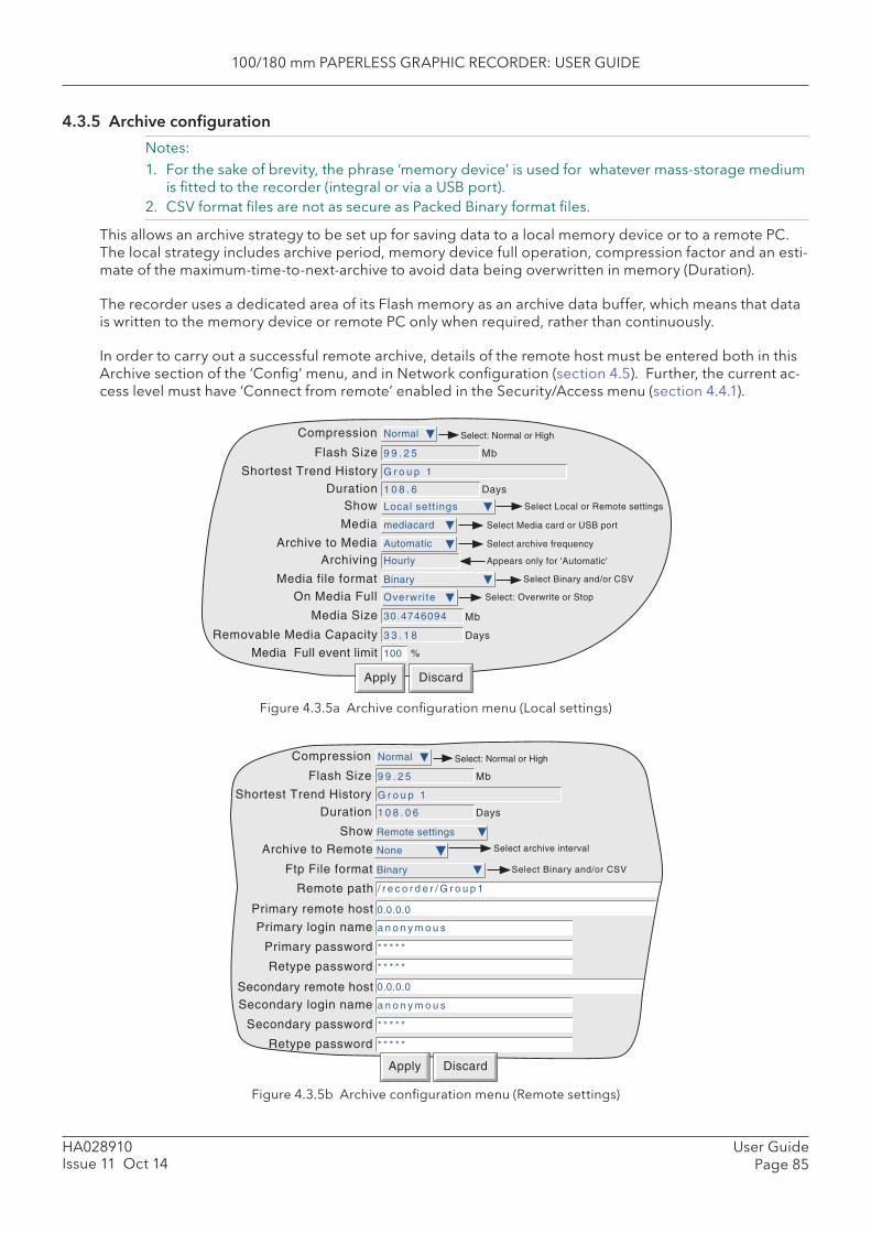
100/180 mm PAPERLESS GRAPHIC RECORDER: USER GUIDE
User GuidePage 85
HA028910Issue 11 Oct 14
4.3.5 Archive confi guration
Notes:1. For the sake of brevity, the phrase ‘memory device’ is used for whatever mass-storage medium
is fi tted to the recorder (integral or via a USB port).2. CSV format fi les are not as secure as Packed Binary format fi les.
This allows an archive strategy to be set up for saving data to a local memory device or to a remote PC. The local strategy includes archive period, memory device full operation, compression factor and an esti-mate of the maximum-time-to-next-archive to avoid data being overwritten in memory (Duration).
The recorder uses a dedicated area of its Flash memory as an archive data buffer, which means that data is written to the memory device or remote PC only when required, rather than continuously.
In order to carry out a successful remote archive, details of the remote host must be entered both in this Archive section of the ‘Confi g’ menu, and in Network confi guration (section 4.5). Further, the current ac-cess level must have ‘Connect from remote’ enabled in the Security/Access menu (section 4.4.1).
Figure 4.3.5a Archive confi guration menu (Local settings)
Figure 4.3.5b Archive confi guration menu (Remote settings)
Apply Discard
On Media Full
Media Size 30.4746094 Mb
Overwri te
Media Full event limit
Select: Overwrite or Stop
Removable Media Capacity 3 3 . 1 8 Days
100 %
Archive to Media
Compression
Automatic Select archive frequency
Normal
Flash Size 9 9 . 2 5 Mb
Shortest Trend History G r o u p 1
Select: Normal or High
Show Local sett ings Select Local or Remote settings
Duration 1 0 8 . 6 Days
Media file format Binary
Media mediacard Select Media card or USB port
Select Binary and/or CSV
Archiving Hourly Appears only for 'Automatic'
Archive to Remote None Select archive interval
Remote path
Show Remote settings
0.0.0.0Primary remote host
Primary login name a n o n y m o u s
Primary password * * * * *
Retype password * * * * *
0.0.0.0Secondary remote hostSecondary login name a n o n y m o u s
Secondary password * * * * *
Retype password * * * * *
/ r e c o r d e r / G r o u p 1
Compression Normal
Flash Size 9 9 . 2 5 Mb
Shortest Trend History G r o u p 1
Select: Normal or High
Duration 1 0 8 . 0 6 Days
Ftp File format Binary Select Binary and/or CSV
Apply Discard

100/180 mm PAPERLESS GRAPHIC RECORDER: USER GUIDE
HA028910Issue 11 Oct 14
User GuidePage 86
4.3.5 ARCHIVE CONFIGURATION (Cont.)
COMPRESSION
Select Normal or High compression. ‘Normal’ compresses the data but still provides an exact copy. ‘High’ compresses more, but channel values are saved only to 1 part in 108 resolution. This fi eld does not appear if ‘CSV’ is selected as fi le format (see below).
Note: Where very high values are involved (e.g. some totaliser values) ‘High’ compression may cause the value displayed by the recorder, and held in the history fi le, to be incorrect. This prob-lem may be solved by moving the relevant point to a group using ‘Normal’ compression, or by re-scaling the totaliser to read (for example) TeraWatt hours instead of Megawatt hours.
FLASH SIZE
Allows the size of the internal fl ash memory to be viewed by the user.
SHORTEST TREND HISTORY / DURATION
This shows which group has the shortest amount of Flash memory allocated to its history record. Provid-ing the archive period is less than the value displayed in the Duration window, no data will be lost from any group. If the archive period is greater than this value, then some of the data in one or more groups will have been overwritten and therefore lost.
If there is more than one group with the same Shortest Trend History Duration, the group with the lowest number is displayed. (E.G. If groups two and four both have the same duration, ‘Group 2’ will appear in this window.)
Note: Trend history duration depends on many factors, as described in Group Confi guration (sec-tion 4.3.2) above.
CSV CHECK BOXES, DATE/TIME FORMAT
These appear only if the ‘Media File Format’ or ‘FTP fi le format’ are set to either ‘ CSV’ or ‘ Binary and CSV’. Refer to ‘CSV Files’ at the end of this subsection (4.3.5).
SHOW
This allows the fi elds which are to appear below ‘Show’ to be applicable to the local memory device (Lo-cal Settings), or to the setting up of a remote host path for archiving purposes (Remote settings). The following descriptions contain all the fi elds which may appear in either menu.
MEDIA
For ‘Local’ setting only
For standard recorders, this allows ‘mediacard or ‘usbfront’’ to be selected as the local archive destina-tion. If the USB option is fi tted, the two rear USB ports (usb1 and usb2) also appear in the pick list. USB ports may support both fl oppy disk drives and ‘memory sticks’.
100/180 mm PAPERLESS GRAPHIC RECORDER: USER GUIDE
User GuidePage 87
HA028910Issue 11 Oct 14
4.3.5 ARCHIVE CONFIGURATION (Cont.)
ARCHIVE TO MEDIA
For ‘Local’ setting only:
None Archive must be initiated by the operator (section 4.1) Hourly Archive occurs on the hour every hour Daily Archive occurs at 00:00* hrs each day Weekly Archive occurs at 00:00* hrs every Monday Monthly Archive occurs at 00:00* hrs on the 1st of each month Automatic The recorder selects the least frequent archive period (Hourly, Daily, Weekly, Month-
ly), which is guaranteed not to lose data as a result of either the internal Flash, or the local memory device, running out of space (calculated assuming that the memory device is initially ‘empty’). When Automatic is selected, a further, non-editable menu item appears, showing which of the archive frequencies has been selected.
*Note: Archive times are not adjusted for Daylight Saving hour changes. Thus if the archive is set to ‘daily’, ‘weekly’ or ‘ monthly’ then, during ‘Summer Time’, the archive will occur an hour late (i.e. at 01:00 hrs. instead of midnight).
MEDIA FILE FORMAT/FTP FILE FORMAT
Allows ‘Binary’ (.uhh) fi les, ‘CSV’ (.csv) fi les or ‘Binary and CSV’ to be chosen for FTP transfer. For further details of CVS archiving, see description at the end of this subsection (4.3.5).
ON MEDIA FULL
For ‘Local’ setting only:
Overwrite Oldest data is replaced with latest data when storage medium is full. Stop Archiving stops when the storage medium is full.
Note: When in ‘Overwrite’ mode, the recorder will overwrite only those fi les which it has itself created. Thus, if a storage medium is inserted which contains history fi les from another recorder, these cannot be overwritten. The fi le names are of the form UUU....UUUIIIIIIFFGGSSSSSS, where IIIIII represent the lowest three bytes of MAC address of the recorder which created the fi le (see section 4.5.1). It is not possible for the user to delete fi les created by another instrument (i.e. one with a different MAC address).
MEDIA SIZE
For ‘Local’ setting only, this displays the capacity of the memory device.
REMOVABLE MEDIA CAPACITY
For ‘Local’ setting only, this gives an estimated time to fi ll the archive medium, based on the archive rate, the compression ratio, the storage medium size and on the exact nature of the data. (Rapidly changing values use more space than static/slowly changing values.) When archiving to Floppy disks (via USB port), this fi eld remains empty until after the fi rst archive has taken place.
MEDIA FULL EVENT LIMIT
For ‘Local’ setting only, this allows the user to specify a percentage-full value for the storage medium, at which the event source ‘Archive media % full’ is triggered. The event remains active until the storage medium is replaced, or has data removed from it to make more room available.

100/180 mm PAPERLESS GRAPHIC RECORDER: USER GUIDE
HA028910Issue 11 Oct 14
User GuidePage 88
4.3.5 ARCHIVE CONFIGURATION (Cont.)
ARCHIVE TO REMOTE
For ‘Remote’ setting only:
None Archive to host is initiated by the operator (section 4.1.2) Hourly Archive to host occurs on the hour every hour Daily Archive to host occurs at 00:00* hrs each day Weekly Archive to host occurs at 00:00* hrs every Monday Monthly Archive to host occurs at 00:00* hrs on the 1st of each month Automatic The recorder selects the slowest out of ‘Hourly’, Daily, Weekly or Monthly, which is
guaranteed not to lose data (depends on the size of the Trend History Buffer).
*Note: Archive times are not adjusted for Daylight Saving hour changes. Thus if the archive is set to ‘daily’, ‘weekly’ or ‘ monthly’ then, during ‘Summer Time’, the archive will occur an hour late (i.e. at 01:00 hrs. instead of midnight).
REMOTE PATH
For Remote setting only, this specifi es the route to a folder or directory on the remote host, set up as a part of that host’s FTP confi guration. The path name may be up to 103 characters in length.
PRIMARY REMOTE HOST
For ‘Remote’ setting only:If a Domain Name Server (DNS) is specifi ed in the Network key ‘Name’ page (fi gure 4.5.2), then the Primary Remote Host is the server name. If DNS is not selected, then the Primary Remote Host is the IP address of the remote host, set up in the host’s Control Panel\Network.
PRIMARY LOGIN NAME/PASSWORD
For ‘Remote’ setting only:Login name and password of the remote host account assigned either by the Network administrator, or in the Guest account of the remote host’s FTP Server or User Manager confi guration. The password, which must be of between eight and 20 characters, must be entered twice to ensure integrity.
SECONDARY REMOTE HOST/LOGIN/PASSWORD
For ‘Remote’ setting only:As for primary versions, but for a secondary host. The secondary route is used only if the primary route fails.
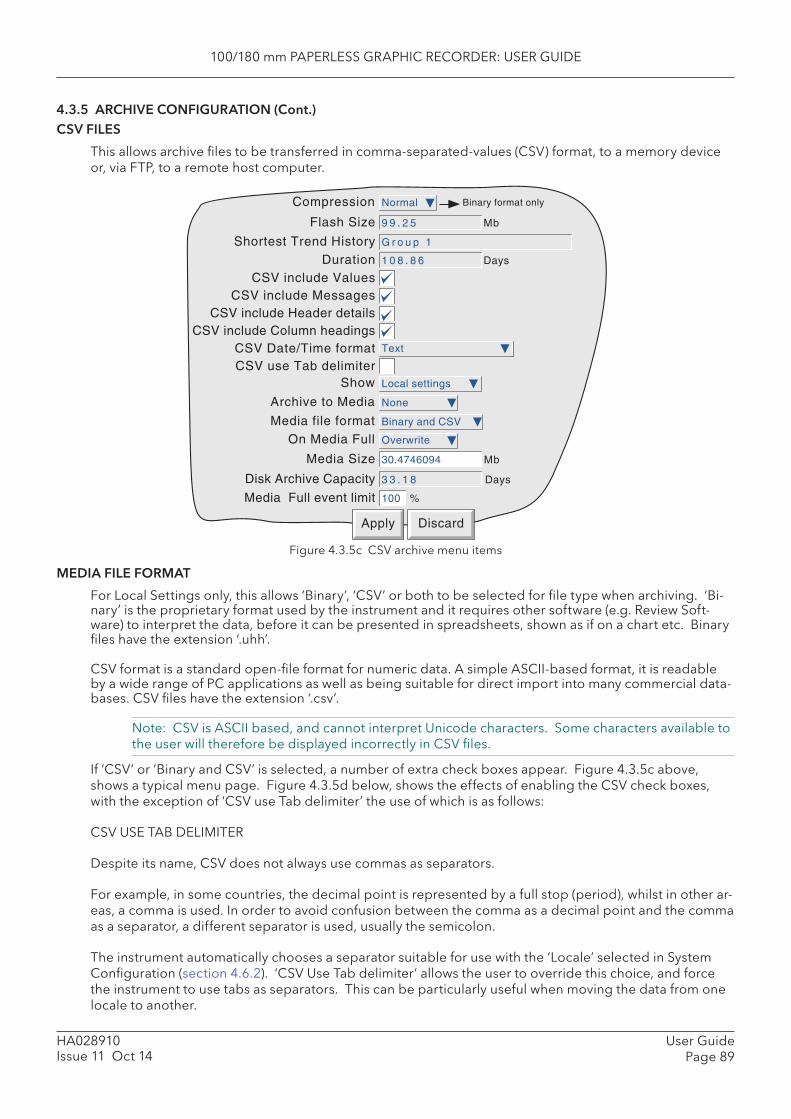
100/180 mm PAPERLESS GRAPHIC RECORDER: USER GUIDE
User GuidePage 89
HA028910Issue 11 Oct 14
4.3.5 ARCHIVE CONFIGURATION (Cont.) CSV FILES
This allows archive fi les to be transferred in comma-separated-values (CSV) format, to a memory device or, via FTP, to a remote host computer.
Figure 4.3.5c CSV archive menu items
MEDIA FILE FORMAT
For Local Settings only, this allows ‘Binary’, ‘CSV’ or both to be selected for fi le type when archiving. ‘ Bi-nary’ is the proprietary format used by the instrument and it requires other software (e.g. Review Soft-ware) to interpret the data, before it can be presented in spreadsheets, shown as if on a chart etc. Binary fi les have the extension ‘.uhh’.
CSV format is a standard open-fi le format for numeric data. A simple ASCII-based format, it is readable by a wide range of PC applications as well as being suitable for direct import into many commercial data-bases. CSV fi les have the extension ‘.csv’.
Note: CSV is ASCII based, and cannot interpret Unicode characters. Some characters available to the user will therefore be displayed incorrectly in CSV fi les.
If ‘CSV’ or ‘Binary and CSV’ is selected, a number of extra check boxes appear. Figure 4.3.5c above, shows a typical menu page. Figure 4.3.5d below, shows the effects of enabling the CSV check boxes, with the exception of ‘CSV use Tab delimiter’ the use of which is as follows:
CSV USE TAB DELIMITER
Despite its name, CSV does not always use commas as separators.
For example, in some countries, the decimal point is represented by a full stop (period), whilst in other ar-eas, a comma is used. In order to avoid confusion between the comma as a decimal point and the comma as a separator, a different separator is used, usually the semicolon.
The instrument automatically chooses a separator suitable for use with the ‘Locale’ selected in System Confi guration (section 4.6.2). ‘CSV Use Tab delimiter’ allows the user to override this choice, and force the instrument to use tabs as separators. This can be particularly useful when moving the data from one locale to another.
Apply Discard
On Media Full
Media Size Mb
Media Full event limit
Disk Archive Capacity Days
%
Archive to Media
Compression
Flash Size Mb
Shortest Trend History
Binary format only
Show
Duration Days
Media file format
CSV include ValuesCSV include Messages
CSV include Header detailsCSV include Column headings
CSV Date/Time formatCSV use Tab delimiter
30.4746094
Overwrite
3 3 . 1 8
100
None
Normal
9 9 . 2 5
G r o u p 1
Local settings
Binary and CSV
Text
1 0 8 . 8 6
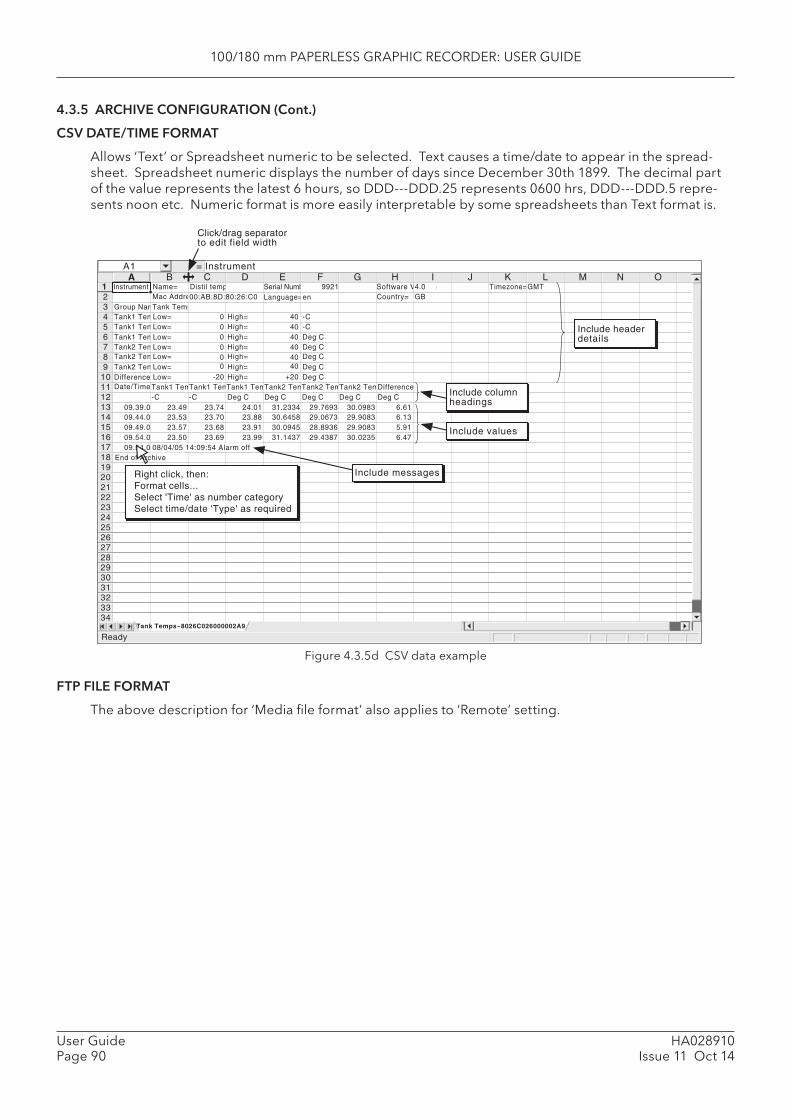
100/180 mm PAPERLESS GRAPHIC RECORDER: USER GUIDE
HA028910Issue 11 Oct 14
User GuidePage 90
4.3.5 ARCHIVE CONFIGURATION (Cont.)
CSV DATE/TIME FORMAT
Allows ‘Text’ or Spreadsheet numeric to be selected. Text causes a time/date to appear in the spread-sheet. Spreadsheet numeric displays the number of days since December 30th 1899. The decimal part of the value represents the latest 6 hours, so DDD---DDD.25 represents 0600 hrs, DDD---DDD.5 repre-sents noon etc. Numeric format is more easily interpretable by some spreadsheets than Text format is.
Figure 4.3.5d CSV data example
FTP FILE FORMAT
The above description for ‘Media fi le format’ also applies to ‘Remote’ setting.
Tank1 Temp1Tank1 Temp2Tank1 Temp3Tank2 Temp1Tank2 Temp2Tank2 Temp3
Group Name
Difference
Tank Temps
Date/Time
Mac AddressName=
Tank1 Temp1Tank1 Temp1Tank1 Temp1Tank2 Temp1Tank2 Temp2Tank2 Temp3
Distil temp Timezone=Country=Software Version
Language=Serial Number
A B C D E F G H I J K L M N O
23456789
10111213141516171819202122232425262728293031323334
00:AB:8D:80:26:C0Instrument1 9921
en4.0GB
GMT
09.39.0-C -C Deg C Deg C Deg C Deg C
23.49 23.74 24.01 31.2334 29.7693 30.098309.44.0 23.53 23.70 23.88 30.6458 29.0673 29.908309.49.0 23.57 23.68 23.91 30.0945 28.8936 29.908309.54.0 23.50 23.69 23.99 31.1437 29.4387 30.0235
A1 = Instrument
ReadyTank Temps~8026C026000002A9
Click/drag separatorto edit field width
Low=Low=Low=Low=Low=Low=
000000
Low= -20
High=High=High=High=High=High=
404040404040
High= +20
-C-CDeg CDeg CDeg CDeg CDeg C
DifferenceDeg C
6.616.135.916.47
Include columnheadings
Include values
Include headerdetails
09.54.0 08/04/05 14:09:54 Alarm offEnd of Archive
Right click, then:Format cells...Select 'Time' as number categorySelect time/date 'Type' as required
Include messages
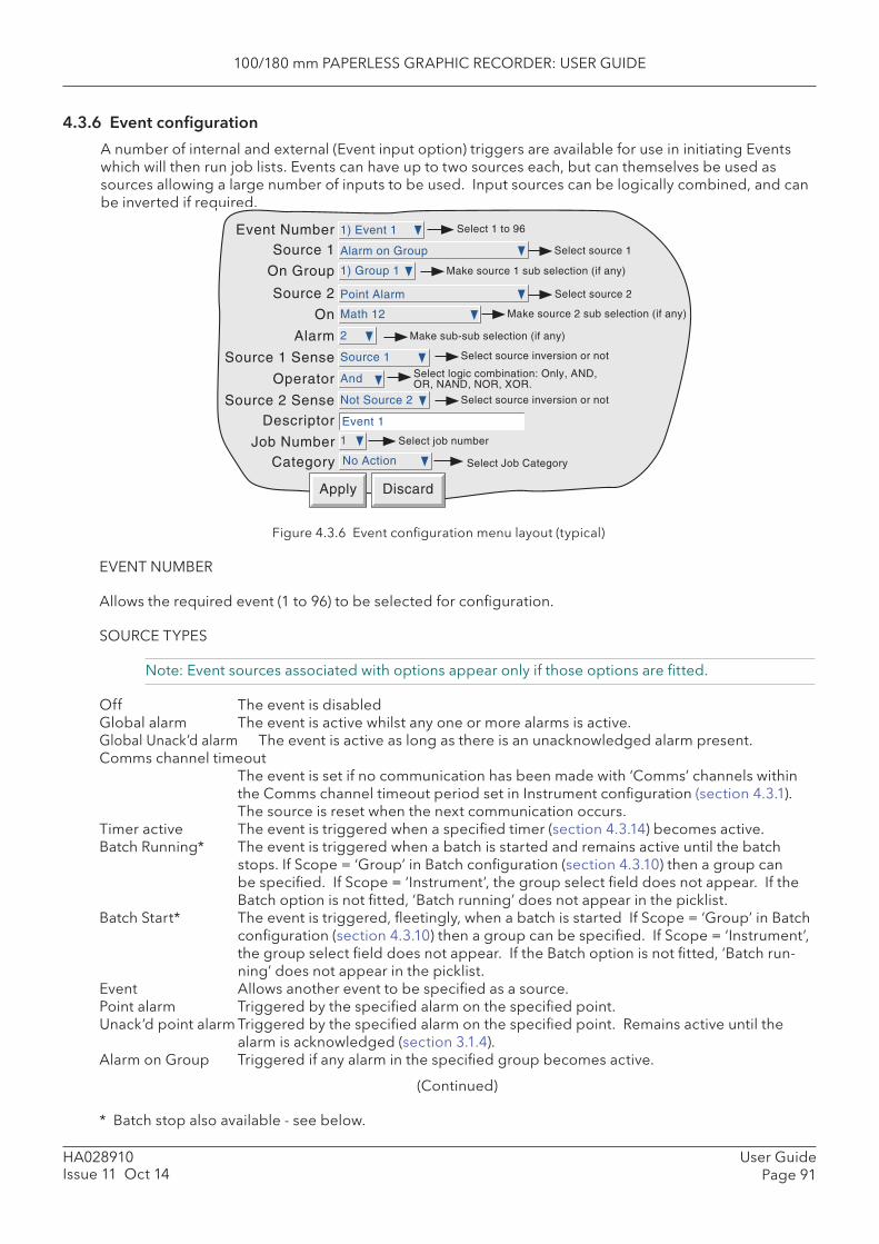
100/180 mm PAPERLESS GRAPHIC RECORDER: USER GUIDE
User GuidePage 91
HA028910Issue 11 Oct 14
4.3.6 Event confi guration
A number of internal and external (Event input option) triggers are available for use in initiating Events which will then run job lists. Events can have up to two sources each, but can themselves be used as sources allowing a large number of inputs to be used. Input sources can be logically combined, and can be inverted if required.
Figure 4.3.6 Event confi guration menu layout (typical)
EVENT NUMBER
Allows the required event (1 to 96) to be selected for confi guration.
SOURCE TYPES
Note: Event sources associated with options appear only if those options are fi tted.
Off The event is disabled Global alarm The event is active whilst any one or more alarms is active. Global Unack’d alarm The event is active as long as there is an unacknowledged alarm present. Comms channel timeout
The event is set if no communication has been made with ‘Comms’ channels within the Comms channel timeout period set in Instrument confi guration (section 4.3.1). The source is reset when the next communication occurs.
Timer active The event is triggered when a specifi ed timer (section 4.3.14) becomes active. Batch Running* The event is triggered when a batch is started and remains active until the batch
stops. If Scope = ‘Group’ in Batch confi guration (section 4.3.10) then a group can be specifi ed. If Scope = ‘Instrument’, the group select fi eld does not appear. If the Batch option is not fi tted, ‘Batch running’ does not appear in the picklist.
Batch Start* The event is triggered, fl eetingly, when a batch is started If Scope = ‘Group’ in Batch confi guration (section 4.3.10) then a group can be specifi ed. If Scope = ‘Instrument’, the group select fi eld does not appear. If the Batch option is not fi tted, ‘Batch run-ning’ does not appear in the picklist.
Event Allows another event to be specifi ed as a source. Point alarm Triggered by the specifi ed alarm on the specifi ed point. Unack’d point alarm Triggered by the specifi ed alarm on the specifi ed point. Remains active until the
alarm is acknowledged (section 3.1.4). Alarm on Group Triggered if any alarm in the specifi ed group becomes active.
(Continued)
* Batch stop also available - see below.
Apply Discard
Select 1 to 96Event Number 1) Event 1
Event 1
1
No Action
Alarm on Group
1) Group 1
Point Alarm
Math 12
2
Source 1
And
Not Source 2
Source 1
DescriptorSelect job numberJob Number
Category Select Job Category
Select source 1
On Group
Source 2 Select source 2
On
Alarm
Source 1 Sense
Operator
Source 2 Sense
Make sub-sub selection (if any)
Select logic combination: Only, AND,OR, NAND, NOR, XOR.
Select source inversion or not
Select source inversion or not
Make source 1 sub selection (if any)
Make source 2 sub selection (if any)
100/180 mm PAPERLESS GRAPHIC RECORDER: USER GUIDE
HA028910Issue 11 Oct 14
User GuidePage 92
4.3.6 EVENT CONFIGURATION (Cont.)
EVENT SOURCES (Cont.)
Unack’d Alarm on Group Triggered if any alarm in the specifi ed group becomes active. The event remains active until the alarm is acknowledged.
Instrument alarm This source triggers an event if any of the following becomes active: Any, Input channel failure, Removable media failure, Removable media
full, No removable media fi tted, FTP primary server failure, FTP secondary server failure, Maths channel failure, Clock failure, Unrecognised PCCard, Recording failure - overfl ow, Network not found, SNTP server failure, Time synchronisation failure, Battery backed RAM cleared. See section 3.1.3 for Instrument alarm details.The event remains active until the instrument alarm clears.
Power up A transient event is triggered at power up. Maths channel partial failure For recorders fi tted with Maths channels (section 4.3.11), this event is set if,
say, one of the inputs to a group averaging function becomes invalid. In such a case, the average will be calculated on the remaining input values, but the result may not be as accurate as expected. Loss of one input can also be important in functions such as Fvalue, where several sensors may be distributed within the load and their outputs used in a group minimum calculation for input into the Fvalue equation.
Battery Low This event is set when the battery is reaching the end of its useful life. The event remains active until the battery is replaced (see Annex B for details).
Archive media % full Triggered when the archive medium has reached the % fullness defi ned in Archive confi guration (section 4.3.5).
Invalid Password Entry Transient event at the point of an invalid password entry attempt User Login Account Disabled Transient event at the point when an account is disabled because the
number of password re-tries has been exceeded (Section 4.4.2). Available only if the Auditor 21CFR11 option is fi tted.
User Logged In This event becomes active whenever a user with the specifi ed Event Per-mission logs in. The event remains active until all local and remote users, with the specifi ed permission, have logged out. See also section 4.4.1 (Ac-cess levels).
Event Button Allows the operation of an event button (if Screen Builder option fi tted - section 7) to be used as an event source. See section 4.3.7 for Event But-ton details.
Master Comms Slave Failure If the Master Comms option is fi tted, this event source allows either a com-munications failure with a specifi able remote device, or communications failure with ‘Any’ connected remote device to be used as an event source. See section 4.3.16 for more details.
Event input board If one or more Event Input option boards are fi tted, this allows a contact closure or negative going voltage signal to be used as an event source. The required input is defi ned by specifying a Board number and an Input number. Refer to Section 10 for more details. The menu item does not ap-pear if Event input boards are not fi tted.
Email Failure Triggered if an attempt to send an e-mail (section 4.3.19) is unsuccessful. Batch Stop The event is triggered, fl eetingly, when a batch is stopped. If Scope =
‘Group’ in Batch confi guration (section 4.3.10) then a group can be speci-fi ed. If Scope = ‘Instrument’, the group select fi eld does not appear. If the Batch option is not fi tted, ‘Batch Stop’ does not appear in the picklist.
SOURCE 1 SENSE
Allows source 1 to be used in its normal sense (Select ‘Source 1’) or inverted (Select ‘Not Source 1’).
Example: Source 1 is alarm 1 on channel 3With Source 1 Sense = Source 1, the event is active whenever channel 3 alarm 1 is active. With Source 1 Sense = Not Source 1, the event is active whenever the alarm is not active.

100/180 mm PAPERLESS GRAPHIC RECORDER: USER GUIDE
User GuidePage 93
HA028910Issue 11 Oct 14
4.3.6 EVENT CONFIGURATION (Cont.)
OPERATOR
This allows a logical combination of input sources to be used to trigger an event. The selections and their defi nitions are shown in table 4.3.6, below.
Table 4.3.6 Logical operators for event sources
SOURCE 2 SENSE
Allows source 2 to be used in its normal sense (Select ‘Source 2’) or inverted (Select ‘Not Source 2’). Example: Source 2 is Group 1 Batch RunningWith Source 2 Sense = Source 2, the event is active whilst the batch is running. With Source 2 Sense = Not Source 2, the event is active whilst the batch is not running.
DESCRIPTORAllows a text string to be entered as the event title. See section 3.3.1 for text entry techniques.
JOB NUMBERSelect the required job number for this event.
CATEGORYSelect the required job to be carried out when the channel is in alarm (e.g. Drive relay) See section 4.7 for a description of job categories.
WHILE/ONAllows the action of the alarm job to be chosen as a. while active, while inactive or while unacknowledged for continuous jobs (e.g. drive relay), or, b. on going active, on going inactive or on acknowledgement for ‘one-shot’ jobs (e.g. increment counter).
See also fi gure 4.3.3g and associated text.
EVENT EXAMPLEAn event is to be active whenever Channel 1 Alarm 1 is active whilst Channel 3 alarm 2 is not active.
Source 1 = Point alarm (On = Channel 1; Alarm = 1)Source 2 = Point alarm (On = Channel 3; Alarm = 2)Source 1 Sense = Source 1Operator = AndSource 2 Sense = Not Source 2
It is possible to achieve the same result by inverting both Source senses and using the Nor operator.
Operator Event active when: Event not active when:
Only S1 Active S1 not active
AND S1 and S2 both active S1 and/or S2 not active
OR S1 and/or S2 active S1 and S2 both not active
NAND S1 and/or S2 not active S1 and S2 both active
NOR S1 and S2 both not active S1 and/or S2 both active
XOR S1 or S2 activeS1 and S2 both active or both not
activeS1 = Source 1; S2 = Source 2
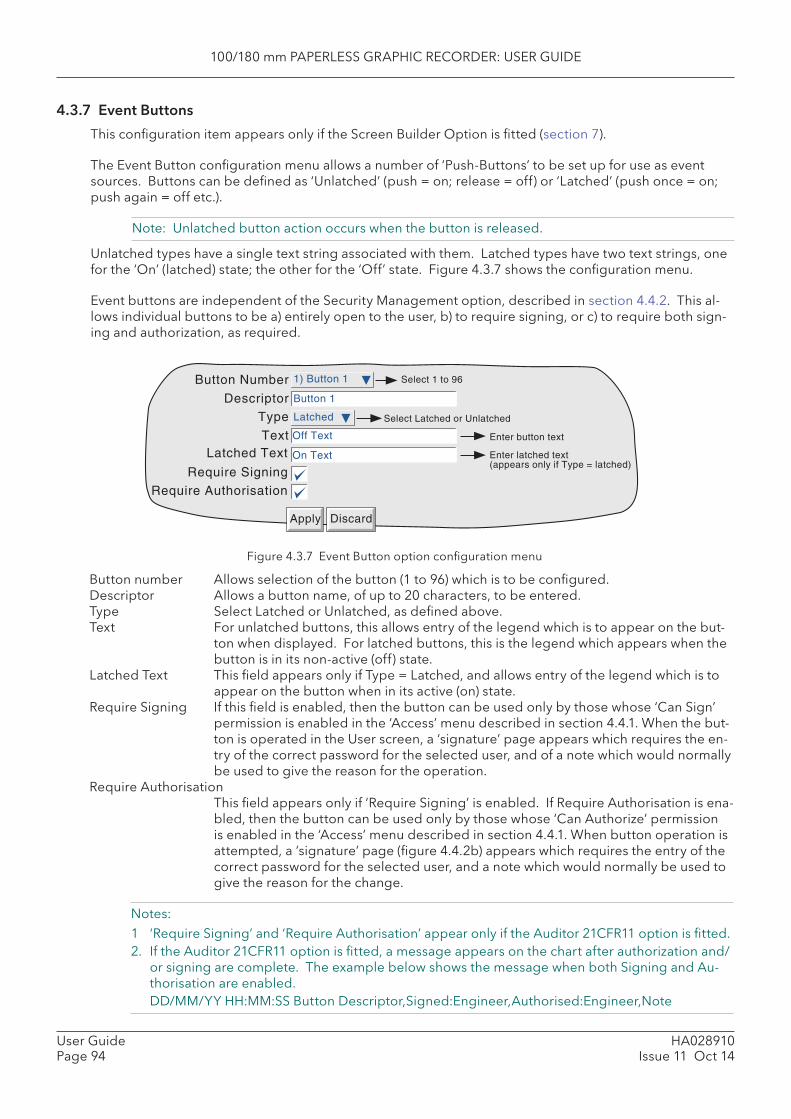
100/180 mm PAPERLESS GRAPHIC RECORDER: USER GUIDE
HA028910Issue 11 Oct 14
User GuidePage 94
4.3.7 Event Buttons
This confi guration item appears only if the Screen Builder Option is fi tted (section 7).
The Event Button confi guration menu allows a number of ‘Push-Buttons’ to be set up for use as event sources. Buttons can be defi ned as ‘Unlatched’ (push = on; release = off) or ‘Latched’ (push once = on; push again = off etc.).
Note: Unlatched button action occurs when the button is released.
Unlatched types have a single text string associated with them. Latched types have two text strings, one for the ‘On’ (latched) state; the other for the ‘Off’ state. Figure 4.3.7 shows the confi guration menu.
Event buttons are independent of the Security Management option, described in section 4.4.2. This al-lows individual buttons to be a) entirely open to the user, b) to require signing, or c) to require both sign-ing and authorization, as required.
Figure 4.3.7 Event Button option confi guration menu
Button number Allows selection of the button (1 to 96) which is to be confi gured. Descriptor Allows a button name, of up to 20 characters, to be entered. Type Select Latched or Unlatched, as defi ned above. Text For unlatched buttons, this allows entry of the legend which is to appear on the but-
ton when displayed. For latched buttons, this is the legend which appears when the button is in its non-active (off) state.
Latched Text This fi eld appears only if Type = Latched, and allows entry of the legend which is to appear on the button when in its active (on) state.
Require Signing If this fi eld is enabled, then the button can be used only by those whose ‘Can Sign’ permission is enabled in the ‘Access’ menu described in section 4.4.1. When the but-ton is operated in the User screen, a ‘signature’ page appears which requires the en-try of the correct password for the selected user, and of a note which would normally be used to give the reason for the operation.
Require Authorisation This fi eld appears only if ‘Require Signing’ is enabled. If Require Authorisation is ena-bled, then the button can be used only by those whose ‘Can Authorize’ permission is enabled in the ‘Access’ menu described in section 4.4.1. When button operation is attempted, a ‘signature’ page (fi gure 4.4.2b) appears which requires the entry of the correct password for the selected user, and a note which would normally be used to give the reason for the change.
Notes:1 ‘Require Signing’ and ‘Require Authorisation’ appear only if the Auditor 21CFR11 option is fi tted.2. If the Auditor 21CFR11 option is fi tted, a message appears on the chart after authorization and/
or signing are complete. The example below shows the message when both Signing and Au-thorisation are enabled.
DD/MM/YY HH:MM:SS Button Descriptor,Signed:Engineer,Authorised:Engineer,Note
Button Number
DescriptorType
TextLatched Text
Require Signing
Require Authorisation
Apply Discard
Select Latched or Unlatched
Select 1 to 96
Enter button text
Enter latched text(appears only if Type = latched)
1) Button 1
Button 1
Latched
Off Text
On Text
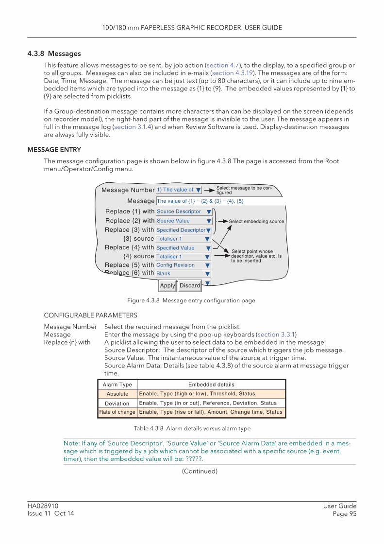
100/180 mm PAPERLESS GRAPHIC RECORDER: USER GUIDE
User GuidePage 95
HA028910Issue 11 Oct 14
4.3.8 Messages
This feature allows messages to be sent, by job action (section 4.7), to the display, to a specifi ed group or to all groups. Messages can also be included in e-mails (section 4.3.19). The messages are of the form: Date, Time, Message. The message can be just text (up to 80 characters), or it can include up to nine em-bedded items which are typed into the message as {1} to {9}. The embedded values represented by {1} to {9} are selected from picklists.
If a Group-destination message contains more characters than can be displayed on the screen (depends on recorder model), the right-hand part of the message is invisible to the user. The message appears in full in the message log (section 3.1.4) and when Review Software is used. Display-destination messages are always fully visible.
MESSAGE ENTRY
The message confi guration page is shown below in fi gure 4.3.8 The page is accessed from the Root menu/Operator/Confi g menu.
Figure 4.3.8 Message entry confi guration page.
CONFIGURABLE PARAMETERS
Message Number Select the required message from the picklist. Message Enter the message by using the pop-up keyboards (section 3.3.1) Replace {n} with A picklist allowing the user to select data to be embedded in the message: Source Descriptor: The descriptor of the source which triggers the job message. Source Value: The instantaneous value of the source at trigger time. Source Alarm Data: Details (see table 4.3.8) of the source alarm at message trigger
time.
Table 4.3.8 Alarm details versus alarm type
Note: If any of ‘Source Descriptor’, ‘Source Value’ or ‘Source Alarm Data’ are embedded in a mes-sage which is triggered by a job which cannot be associated with a specifi c source (e.g. event, timer), then the embedded value will be: ?????.
(Continued)
Message Number
Message
Replace {1} with
Replace {2} with
Replace {3} with{3} source
Replace {4} with{4} source
Replace {5} with
Select embedding source
Replace {6} with
Select point whosedescriptor, value etc. isto be inserted
Select message to be con-figured
Apply Discard
1) The value of
The value of {1} = {2} & {3} = {4}, {5}
Source Descriptor
Source Value
Totaliser 1
Specified Descriptor
Totaliser 1
Specified Value
Config Revision
Blank
Absolute Enable, Type (high or low), Threshold, Status
Deviation Enable, Type (in or out), Reference, Deviation, Status
Rate of change Enable, Type (rise or fall), Amount, Change time, Status
Alarm Type Embedded details
100/180 mm PAPERLESS GRAPHIC RECORDER: USER GUIDE
HA028910Issue 11 Oct 14
User GuidePage 96
4.3.8 MESSAGES (Cont.)
Replace {n} with (Cont.)
Specifi ed Descriptor, Specifi ed Value, Specifi ed Alarm data: Produces a further fi eld ‘{n} source’, described below.
Batch Status: Causes the status (‘Active’ or ‘Inactive’) of the current batch to be em-bedded. See Section 4.3.10 for details of the Batch option.
Batch Field data: Allows a selected batch fi eld to be included in the message. If a batch is not running at the time the message is triggered, the Batch fi eld data is replaced by ‘?????’. See Section 4.3.10 for details of the Batch option.
Note: Group number must be entered if the batch is confi gured for Group mode.
Instrument Name: Allows the Instrument Name (as entered in Confi guration/Instru-ment - section 4.3.1) to be included in the message.
Instrument Number: Causes the instrument number (Network/Address - Section 4.5.1) to be embedded.
Confi g Revision: Embeds the Confi g File Version number (System/About - section 4.6.11) in the message
Local User: Embeds the currently logged-in user (e.g. ‘Engineer’, ‘JohnW’, etc.)
{n} source This fi eld appears only if the previous fi eld (Replace {n} with) is selected as ‘Specifi ed Descriptor’, ‘Specifi ed Value’ or ‘Specifi ed alarm data’. The associated picklist(s) allow a specifi c point, and a specifi c alarm (if appropriate) to be selected. It is thus possi-ble to confi gure, say alarm 1 on channel 2, to produce a message giving the descrip-tor and/or value of, say, totaliser 1.
Notes:1. n = 1 to 92. The example below is intended to clarify message entry techniques.

100/180 mm PAPERLESS GRAPHIC RECORDER: USER GUIDE
User GuidePage 97
HA028910Issue 11 Oct 14
4.3.8 MESSAGES (Cont.)
EXAMPLE
To confi gure Message 2 to read “The value of Chan two = (Value channel 2) & Tot one = (Value totaliser 1)”
Before confi guring the message:
In channel confi guration: Set channel 2 descriptor to: Chan two Set Channel 2 alarm job to: Category: Message Send message(s) to: All Groups First message: 2) Message 2 Last Message: 2) Message 2 On: ActiveIn Totaliser confi guration: Set Totaliser 1 descriptor to: Tot one
In Messages confi guration:1. Select Message 2.2. Access the Symbols keyboard (section 3.3.1) and enter, without spaces, {}={}&{}={}3. Access the Numeric keyboard and insert 1, 2, 3, 4 within the braces to give: {1}={2}&{3}={4}4. Access the Alphabet keyboard, and insert text and spaces: The value of {1} = {2} & {3} = {4}5. Set ‘Replace {1}’ to “Source Descriptor’6. Set ‘Replace {2}’ to ‘Source Value’7. Set ‘Replace {3}’ to ‘Specifi ed Descriptor’8. Set ‘{3} source’ to Tot one9. Set ‘Replace {4}’ to ‘Specifi ed Value’10. Set ‘{4} source’ to ‘Tot one’
The result of this is that, should the channel 2 alarm go active, the following message would be sent to all groups, appear on the ‘chart’ and become part of all groups’ histories:
18/10/01 11:19:58 The value of Chan two = 6.0˚C & Tot one = 3383.8073 Units
Note: On some models, the message may be wider than the screen. If necessary, the message can be shortened (e.g. use ‘Ch2’ instead of ‘Chan two’), or it can be viewed in full, either in Mes-sage log, (section 3.1.4) or by using Review Software, if available.
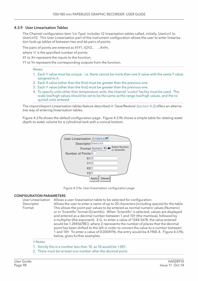
100/180 mm PAPERLESS GRAPHIC RECORDER: USER GUIDE
HA028910Issue 11 Oct 14
User GuidePage 98
4.3.9 User Linearisation Tables
The Channel confi guration item ‘Lin Type’ includes 12 linearisation tables called, initially, UserLin1 to UserLin12. This User Linearisation part of the instrument confi guration allows the user to enter linearisa-tion look-up tables of between two and 66 pairs of points.
The pairs of points are entered as X1Y1, X2Y2... ...XnYn, where ‘n’ is the specifi ed number of points. X1 to Xn represent the inputs to the function. Y1 to Yn represent the corresponding outputs from the function.
Notes: 1. Each Y value must be unique - i.e. there cannot be more than one X value with the same Y value
assigned to it.2. Each X value (other than the fi rst) must be greater than the previous one.3. Each Y value (other than the fi rst) must be greater than the previous one.4. To specify units other than temperature units, the channel ‘scaled’ facility must be used. The
scale low/high values should be set to be the same as the range low/high values, and the re-quired units entered
The import/export Linearisation tables feature described in ‘Save/Restore’ (section 4.2) offers an alterna-tive way of entering linearisation tables.
Figure 4.3.9a shows the default confi guration page. Figure 4.3.9b shows a simple table for relating water depth to water volume for a cylindrical tank with a conical bottom.
Figure 4.3.9a User linearisation confi guration page
CONFIGURATION PARAMETERS User Linearisation Allows a user linearisation table to be selected for confi guration. Descriptor Allows the user to enter a name of up to 20 characters (including spaces) for the table. Format This allows the point pair values to be entered as normal numeric values (Numeric)
or in ‘Scientifi c’ format (Scientifi c). When ‘Scientifi c’ is selected, values are displayed and entered as a decimal number between 1 and 10† (the mantissa), followed by a multiplier (the exponent). E.G. to enter a value of 1244.5678, the value entered would be 1.2445678E3, where 3 represents the number of places that the decimal point has been shifted to the left in order to convert the value to a number between 1 and 10†. To enter a value of 0.0004196, the entry would be 4.196E-4. Figure 4.3.9b, below, gives further examples.
† Notes 1. Strictly this is a number less than 10, as 10 would be 1.0E1.2. There must be at least one number after the decimal point.
User Linearisation
Descriptor
Format
Number of Points
X1
Y1
X2
3) UserLin3
Numeric
2
0
0
1
1
UserLin3
Apply Discard
Y2
Select Numericor Scientific
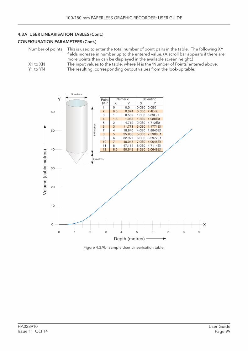
100/180 mm PAPERLESS GRAPHIC RECORDER: USER GUIDE
User GuidePage 99
HA028910Issue 11 Oct 14
4.3.9 USER LINEARISATION TABLES (Cont.)
CONFIGURATION PARAMETERS (Cont.)
Number of points This is used to enter the total number of point pairs in the table. The following XY fi elds increase in number up to the entered value. (A scroll bar appears if there are more points than can be displayed in the available screen height.)
X1 to XN The input values to the table, where N is the ‘Number of Points’ entered above.Y1 to YN The resulting, corresponding output values from the look-up table.
Figure 4.3.9b Sample User Linearisation table.
6.5
me
tre
s3 metres
2 metres
10
20
30
40
50
60
Vo
lum
e (
cub
ic m
etr
es)
0
1 2 3 4 5 6 7 8 9
Depth (metres)
0
1 0 0.0 0.0E0 0.0E02 0.5 0.074 0.5E0 7.4E-23 1 0.589 1.0E0 5.89E-14 1.5 1.988 1.5E0 1.988E05 2 4.712 2.0E0 4.712E06 3 11.771 3.0E0 1.1771E17 4 18.840 4.0E0 1.8840E18 5 25.908 5.0E0 2.5908E19 6 32.977 6.0E0 3.2977E110 7 40.045 7.0E0 4.0045E111 8 47.114 8.0E0 4.7114E112 8.5 50.648 8.5E0 5.0648E1
Numeric ScientificPointpair X Y X Y
X
Y

100/180 mm PAPERLESS GRAPHIC RECORDER: USER GUIDE
HA028910Issue 11 Oct 14
User GuidePage 100
4.3.10 Batch recording option
Batch records form a part of recording history and are included in the normal archiving process to a removable SD or Compact Flash card or to a remote PC (sections 4.1 and 4.3.5). Batches can be initiated directly by the operator (if access permission is granted), automatically whenever a specifi ed counter changes value, by job or remotely via MODBUS/TCP.
Batches can be defi ned as start/stop, or continuous and can incorporate all channels, or just those associ-ated with a specifi ed Group. For start/stop batches, the batch record starts when the batch is started, and continues until it is stopped. For continuous batches, the batch record starts when the batch is started and continues until the next batch is started, or until batch recording is disabled.
When using ‘PC review’ software the ‘Go to Batch’ feature can be used to select a particular batch record.
If ‘ Name fi les by Batch’ is enabled a separate history fi le is created for each batch.
For each batch start, a start message is printed:
DD/MM/YY HH:MM:SS Batch start (User Full Name)
Where DD/MM/YY is the date, HH:MM:SS is the time, and User Full name is either the current user name, the security level (e.g. Engineer) or ‘Automatic’ if the batch has been initiated by job, or ‘Modbus’ if trig-gered remotely. A similar message is printed at Batch Stop. (There are no stop messages associated with continuous batch selection).
In addition to the above start/stop messages, up to six lines of text can, if required, be printed on the ‘chart’ at the start of a batch and, if required, at the end of a batch. The messages are in two parts, which for the sake of this document, are called ‘Headings’ and ‘Values’ The Headings are entered in Fields 1 to 6 in Batch Confi guration. The Values associated with these headings are entered by the op-erator at initiation.
AUDITOR MESSAGES
If either Auditor option is fi tted a Confi g/Security Revision message appears immediately after the Batch Start message:
DD/MM/YY HH:MM:SS Confi g Revision:NNNNNN Security Revision:SSSSSS
DD/MM/YY HH:MM:SS Batch start (User Full Name)
BATCH SUMMARY
A Batch Summary page can be displayed from the Summary menu described in section 3.1.4, above.
THERMAL UNIFORMITY SURVEY (TUS)
Certain aspects of the batch operation are affected by the TUS option. In particular, the operator can be made to carry out an input adjust procedure before the batch starts, after it fi nishes, or both. Full details are to be found in section 15.
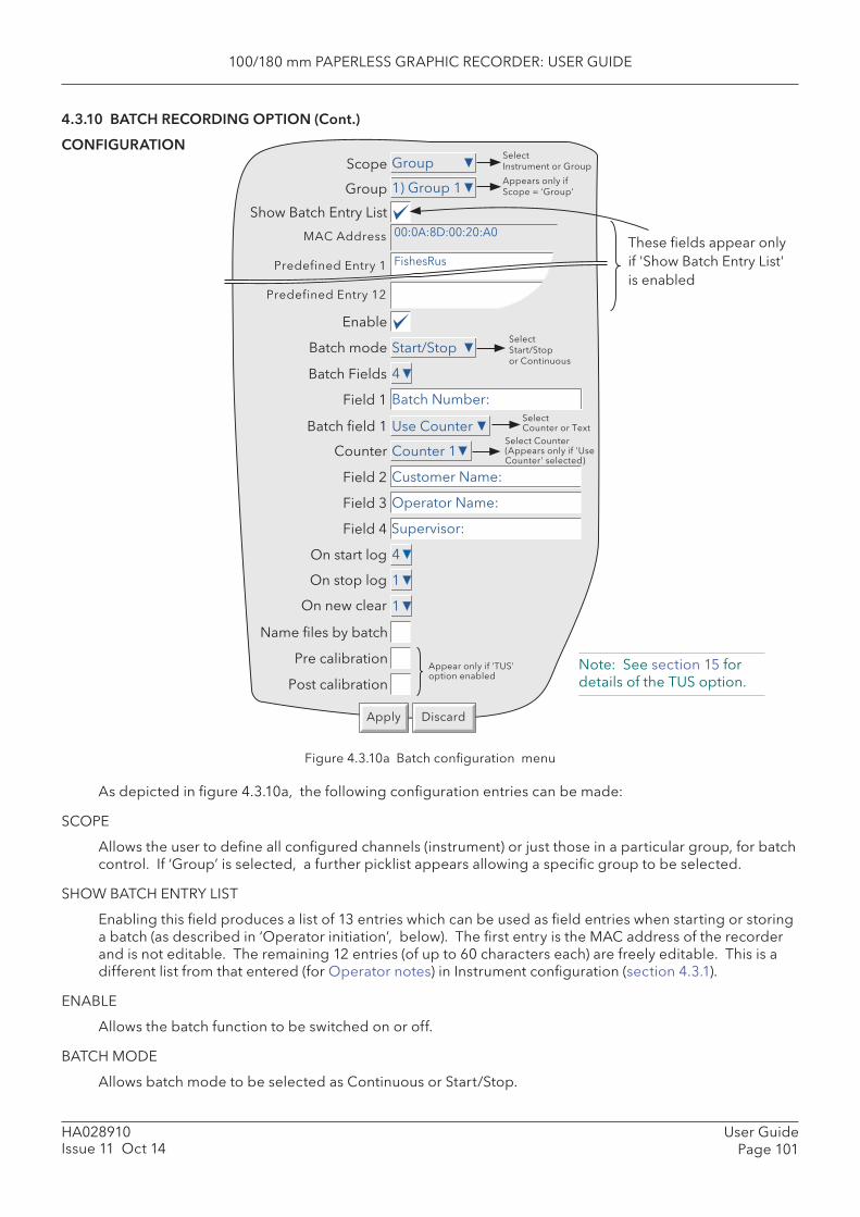
100/180 mm PAPERLESS GRAPHIC RECORDER: USER GUIDE
User GuidePage 101
HA028910Issue 11 Oct 14
4.3.10 BATCH RECORDING OPTION (Cont.)
CONFIGURATION
Figure 4.3.10a Batch confi guration menu
As depicted in fi gure 4.3.10a, the following confi guration entries can be made:
SCOPE
Allows the user to defi ne all confi gured channels (instrument) or just those in a particular group, for batch control. If ‘Group’ is selected, a further picklist appears allowing a specifi c group to be selected.
SHOW BATCH ENTRY LIST
Enabling this fi eld produces a list of 13 entries which can be used as fi eld entries when starting or storing a batch (as described in ‘Operator initiation’, below). The fi rst entry is the MAC address of the recorder and is not editable. The remaining 12 entries (of up to 60 characters each) are freely editable. This is a different list from that entered (for Operator notes) in Instrument confi guration (section 4.3.1).
ENABLE
Allows the batch function to be switched on or off.
BATCH MODE
Allows batch mode to be selected as Continuous or Start/Stop.
Note: See section 15 for details of the TUS option.

100/180 mm PAPERLESS GRAPHIC RECORDER: USER GUIDE
HA028910Issue 11 Oct 14
User GuidePage 102
4.3.10 BATCH RECORDING CONFIGURATION (Cont.)
BATCH FIELDS
Allows the number of messages to be printed at batch start/stop to be selected between one and six.
FIELD 1
This fi eld is the fi rst of up to six which can be used as headings for batch information. Headings can be up to 20 characters long (including spaces). In the example shown in Figure 4.3.10a, Heading 1 (Field 1) has the entry ‘Batch Number:’. When initiating the batch, the operator has to enter a value to be associated with this heading (see below), unless ‘Use Counter’ is selected in the following ‘Batch Number’ fi eld.
BATCH NUMBER
This allows the Value entered for Field 1’s heading to be selected as ‘Use Text’ or ‘Use Counter’.
USE TEXT When Text is selected, the value for fi eld 1 is entered by the operator on initiation of the batch.
USE COUNTER When Counter is selected, a further fi eld appears (‘counter’) allowing a specifi c coun-ter to be selected from a picklist. The selected counter initiates a new batch when-ever it changes value, and the counter value is appended to the text associated with Field 1 (but see note 2). See section 4.3.13 for details of counters.
Notes: 1. Start batch is initiated on any change in counter value - not just increment.2. It is recommended that when ‘Use Counter’ is selected, then only counter 1 be used as the
batch initiator. Other counters may be selected, but operation is not guaranteed.
FIELDS 2 TO 6
Fields 2 to 6 are also used as headings for batch information. Values for these headings must be entered by the operator prior to Batch initiation. See also ‘On new clear’, below. Headings can be up to 20 char-acters long (including spaces).
ON START LOG
This defi nes how many of the selected Fields are to be printed at batch start. An entry of ‘1’ means that only Field 1 will be printed. An entry of ‘2’ means that Fields 1 and 2 will be used, and so on. An entry of 0 means that only the ‘Batch Start’ message will be printed. It is not possible to print only, say, Field 3. If Field 3 is required, it must be preceded by Fields 1 and 2.
ON STOP LOG
As for On start log, above, but for batch stop. This item appears only if Start/Stop is selected as batch mode.
ON NEW CLEAR
For ‘Use Text’ Batches only, this allows the user to clear none or more of the batch entries at each batch start. In the example above, if the user enters a batch number of say 050825.001, with Customer Name: FishesRus, Operator name: Marvin, Supervisor: Fred, then setting ‘On New Clear’ to ‘1’, causes the batch number to be cleared, and to have to be re-entered, each time a new batch is started.
In a similar way, setting ‘On New Clear’ to ‘2’ means that the batch number value and the Customer Name: value to be cleared. A new batch cannot be started without new values fi rst being entered.
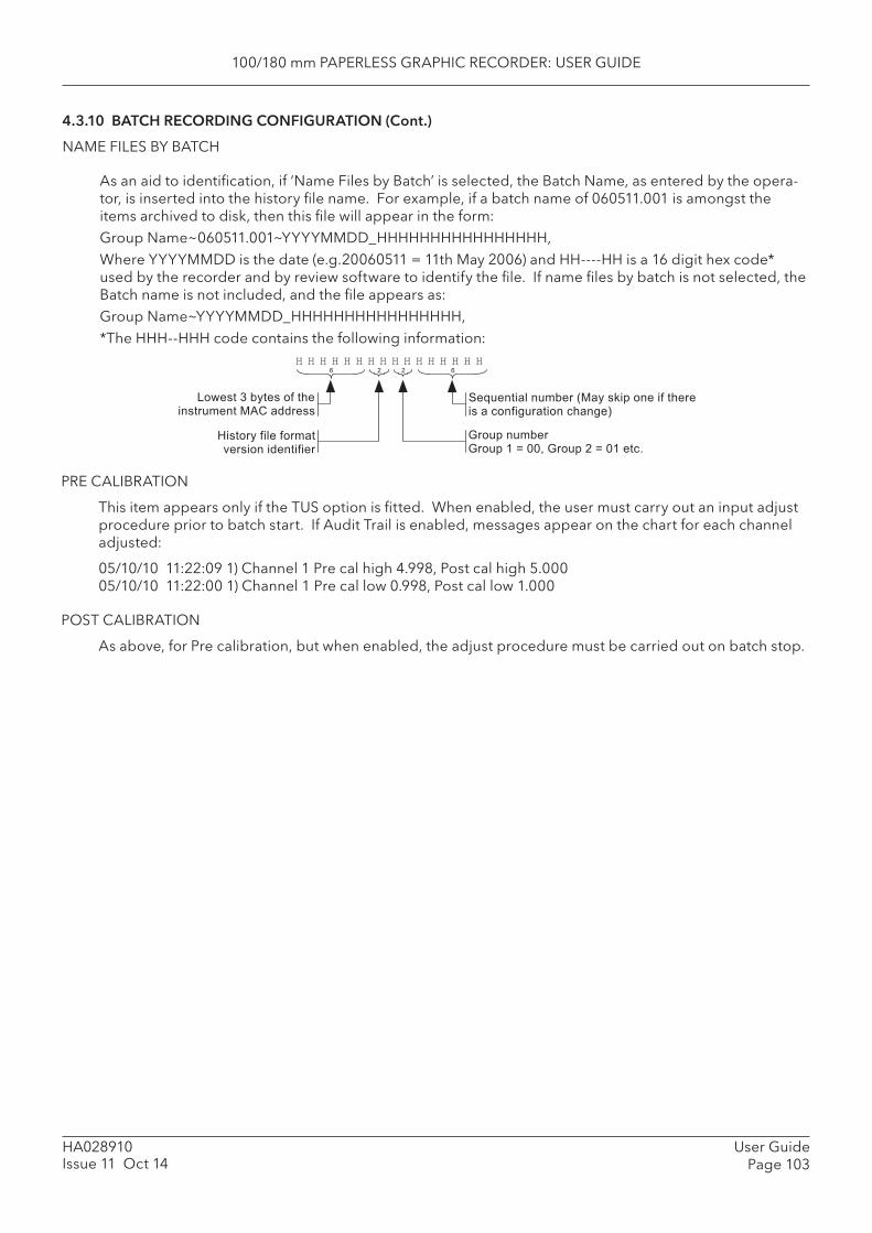
100/180 mm PAPERLESS GRAPHIC RECORDER: USER GUIDE
User GuidePage 103
HA028910Issue 11 Oct 14
4.3.10 BATCH RECORDING CONFIGURATION (Cont.)
NAME FILES BY BATCH
As an aid to identifi cation, if ‘Name Files by Batch’ is selected, the Batch Name, as entered by the opera-tor, is inserted into the history fi le name. For example, if a batch name of 060511.001 is amongst the items archived to disk, then this fi le will appear in the form:Group Name~060511.001~YYYYMMDD_HHHHHHHHHHHHHHHH,Where YYYYMMDD is the date (e.g.20060511 = 11th May 2006) and HH----HH is a 16 digit hex code* used by the recorder and by review software to identify the fi le. If name fi les by batch is not selected, the Batch name is not included, and the fi le appears as:Group Name~YYYYMMDD_HHHHHHHHHHHHHHHH,*The HHH--HHH code contains the following information:
PRE CALIBRATION
This item appears only if the TUS option is fi tted. When enabled, the user must carry out an input adjust procedure prior to batch start. If Audit Trail is enabled, messages appear on the chart for each channel adjusted:
05/10/10 11:22:09 1) Channel 1 Pre cal high 4.998, Post cal high 5.00005/10/10 11:22:00 1) Channel 1 Pre cal low 0.998, Post cal low 1.000
POST CALIBRATION
As above, for Pre calibration, but when enabled, the adjust procedure must be carried out on batch stop.
� � � � � � � � � � � � � � � �
+���� ) ���� �� �� ���� ��� ,"' �������
F����� ���� ����� *������ ���������
$�� � � ���� $�� � � 3 ??5 $�� � ( 3 ?� ��8
��; ����� � ���� 7,�� �6�� ��� �� ���� �� � ������ ����� ������%
1 ( ( 1
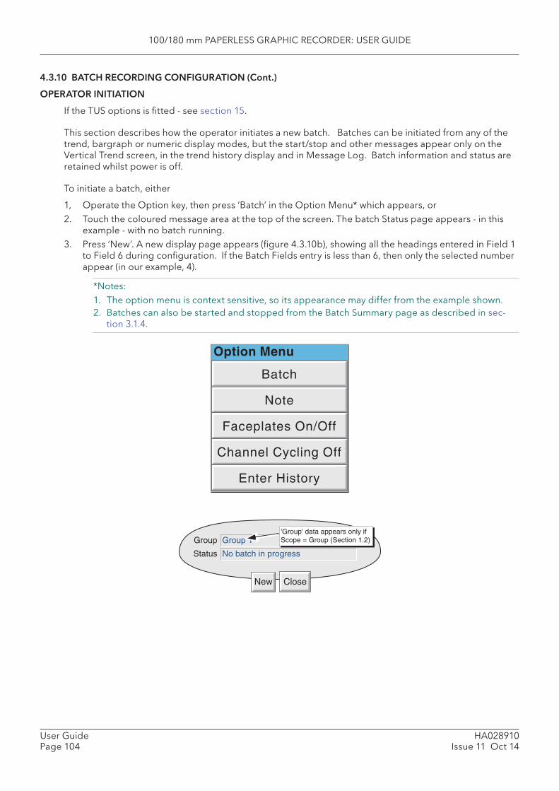
100/180 mm PAPERLESS GRAPHIC RECORDER: USER GUIDE
HA028910Issue 11 Oct 14
User GuidePage 104
4.3.10 BATCH RECORDING CONFIGURATION (Cont.)
OPERATOR INITIATION
If the TUS options is fi tted - see section 15.
This section describes how the operator initiates a new batch. Batches can be initiated from any of the trend, bargraph or numeric display modes, but the start/stop and other messages appear only on the Vertical Trend screen, in the trend history display and in Message Log. Batch information and status are retained whilst power is off.
To initiate a batch, either
1, Operate the Option key, then press ‘Batch’ in the Option Menu* which appears, or 2. Touch the coloured message area at the top of the screen. The batch Status page appears - in this
example - with no batch running.3. Press ‘New’. A new display page appears (fi gure 4.3.10b), showing all the headings entered in Field 1
to Field 6 during confi guration. If the Batch Fields entry is less than 6, then only the selected number appear (in our example, 4).
*Notes:1. The option menu is context sensitive, so its appearance may differ from the example shown.2. Batches can also be started and stopped from the Batch Summary page as described in sec-
tion 3.1.4.
Group 1Group
New Close
No batch in progressStatus
'Group' data appears only ifScope = Group (Section 1.2)
Option Menu
Batch
Enter History
Channel Cycling Off
Faceplates On/Off
Note
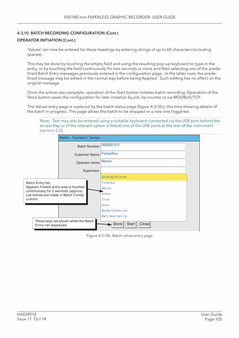
100/180 mm PAPERLESS GRAPHIC RECORDER: USER GUIDE
User GuidePage 105
HA028910Issue 11 Oct 14
4.3.10 BATCH RECORDING CONFIGURATION (Cont.)
OPERATOR INITIATION (Cont.)
‘Values’ can now be entered for these headings by entering strings of up to 60 characters (including spaces).
This may be done by touching the empty fi eld and using the resulting pop-up keyboard to type-in the entry, or by touching the fi eld continuously for two seconds or more and then selecting one of the prede-fi ned Batch Entry messages previously entered in the confi guration page. In the latter case, the prede-fi ned message may be edited in the normal way before being Applied. Such editing has no effect on the original message.
Once the entries are complete, operation of the Start button initiates batch recording. Operation of the Store button saves the confi guration for later initiation by job, by counter or via MODBUS/TCP.
The Values entry page is replaced by the batch status page (fi gure 4.3.10c), this time showing details of the batch in progress. This page allows the batch to be stopped or a new one triggered.
Note: Text may also be entered using a suitable keyboard connected via the USB port behind the access fl ap or (if the relevant option is fi tted) one of the USB ports at the rear of the instrument (section 2.2).
Figure 4.3.10b Batch values entry page
Batch Number:
Customer Name:
Operator name:
Supervisor:
Batch - Furnace1 Temps
Start CloseStore
060509.015
FishesRus
Marvin
00:0A:8D:00:20:A0
FishesRus
Marvin
Arthur
Tricia
Jason
Manky Clothes Ltd.
Rat's Nest Hair Co.
Batch Entry list.Appears if batch entry area is touchedcontinuously for 2 seconds (approx).List entries are made in Batch Config-uration.
These keys not shown whilst the BatchEntry list displayed
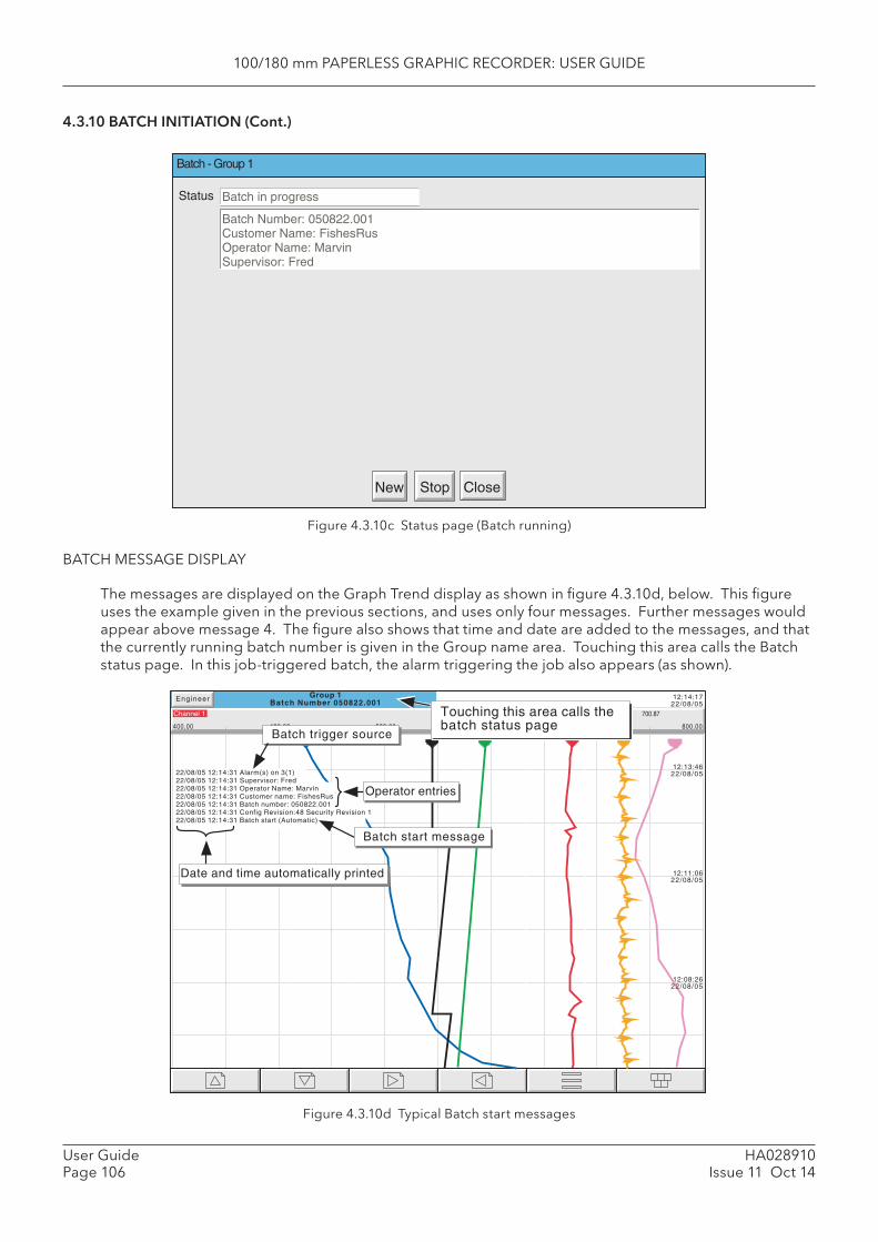
100/180 mm PAPERLESS GRAPHIC RECORDER: USER GUIDE
HA028910Issue 11 Oct 14
User GuidePage 106
4.3.10 BATCH INITIATION (Cont.)
Figure 4.3.10c Status page (Batch running)
BATCH MESSAGE DISPLAY
The messages are displayed on the Graph Trend display as shown in fi gure 4.3.10d, below. This fi gure uses the example given in the previous sections, and uses only four messages. Further messages would appear above message 4. The fi gure also shows that time and date are added to the messages, and that the currently running batch number is given in the Group name area. Touching this area calls the Batch status page. In this job-triggered batch, the alarm triggering the job also appears (as shown).
Figure 4.3.10d Typical Batch start messages
Batch - Group 1
Stop CloseNew
Batch in progressStatus
Batch Number: 050822.001Customer Name: FishesRusOperator Name: MarvinSupervisor: Fred
Channel 1
400.00 800.00
700.87
Group 1Batch Number 050822.001
12:14:1722/08/05
12:13:4622/08/05
12:11:0622/08/05
12:08:2622/08/05
Engineer
720.00640.00
22/08/05 12:14:31 Alarm(s) on 3(1)22/08/05 12:14:31 Supervisor: Fred22/08/05 12:14:31 Operator Name: Marvin22/08/05 12:14:31 Customer name: FishesRus22/08/05 12:14:31 Batch number: 050822.00122/08/05 12:14:31 Config Revision:48 Security Revision 122/08/05 12:14:31 Batch start (Automatic)
Operator entries
Batch start message
480.00 560.00
Touching this area calls thebatch status page
Date and time automatically printed
Batch trigger source

100/180 mm PAPERLESS GRAPHIC RECORDER: USER GUIDE
User GuidePage 107
HA028910Issue 11 Oct 14
4.3.10 BATCH INITIATION (Cont.)
NON OPERATOR INITIATION
Batch start/stop can be initiated by job, by counter or via MODBUS/TCP
JOB INITIATION
As described in section 4.7.9, a job can be set up to initiate a batch whenever the job source becomes active. If ‘Scope’ is set to ‘Group’ a specifi c group can be selected (default = Group 1) and the job will act only on the batch associated with this group. Batch ‘Start’ jobs automatically start the batch using the entries made during the ‘Store’ function, described above. ‘ Display Batch Dialog’ jobs allow the user to enter the fi eld values manually, before the job starts.
COUNTER INITIATION
If Batch Number is selected as ‘Use Counter’, then a new batch will automatically be started whenever the selected counter changes value (increment, decrement or preset). The new value of the counter is used as the value associated with Field 1.
For the other fi elds to have values printed on the chart, these must have been entered as described above for Operator initiation, then the ‘Store’ button touched.
The ‘On new clear’ setting is ignored, the stored values being used each new batch.
Batch start messages are of the form:
DD/MM/YY HH:MM:SS Batch start (Automatic)
Batch recording cannot be stopped by Counter action.
MODBUS INITIATION
In order to initiate batch recording via MODBUS/TCP, a Batch Start fl ag has to be set (value = 0001). For Scope = Group, the fl ag for the specifi ed group must be set. For Scope = Instrument any group’s Batch Start fl ag may be used.
The address of the fl ag for group 1 is decimal 42364; the address for group N is {42364 + 629(N-1)}
For further details of the Modbus TCP option see section 8.
If Batch mode = Start/Stop, batches can also be stopped via MODBUS. The address for group 1 is 42365; the address for group N is {42364 + 629(N-1)}. Again the value must be set to 0001.
Modbus start messages are of the form:
DD/MM/YY HH:MM:SS Batch start (Modbus)
Stop messages are similar.
EVENT SOURCES
As described in section 4.3.6 , ‘ Batch Start’, ‘ Batch Running’ and ‘ Batch Stop’ can be selected as event sources. If ‘Scope’ = ‘Group’ in Confi guration (described above), then the user can select which group’s batch is to be used as the event source.
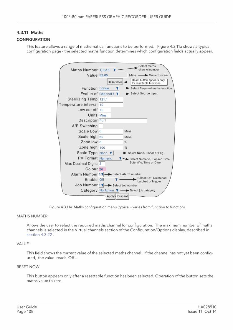
100/180 mm PAPERLESS GRAPHIC RECORDER: USER GUIDE
HA028910Issue 11 Oct 14
User GuidePage 108
4.3.11 Maths
CONFIGURATION
This feature allows a range of mathematical functions to be performed. Figure 4.3.11a shows a typical confi guration page - the selected maths function determines which confi guration fi elds actually appear.
Figure 4.3.11a Maths confi guration menu (typical - varies from function to function)
MATHS NUMBER
Allows the user to select the required maths channel for confi guration. The maximum number of maths channels is selected in the Virtual channels section of the Confi guration/Options display, described in section 4.3.22 .
VALUE
This fi eld shows the current value of the selected maths channel. If the channel has not yet been confi g-ured, the value reads ‘Off’.
RESET NOW
This button appears only after a resettable function has been selected. Operation of the button sets the maths value to zero.
Apply Discard
Select Required maths functionFunction fValue
Fvalue ofSterilizing Temp 121.1
Low cut off
Descriptor Fo 1
Scale Low 0 Mins
Select Source input
Scale Type None Select None, Linear or Log
Zone low 0
Zone high
Max Decimal Digits 2
ColourAlarm Number 1
Enable Off
Job Number 1
Category No Action Select job category
Select: Off, Unlatched,Latched orTrigger
Select Job number
26
Channel 1
75
%
100 %
Maths Number 1) Fo 1Select mathschannel number
Value Current value32.65
Reset now
Mins
Reset button appears onlyfor resettable functions
PV Format Numeric
Select Alarm number
Temperature interval 10
Units Mins
Scale high 60
Select Numeric, Elapsed Time,Scientific, Time or Date
A/B Switching
Mins

100/180 mm PAPERLESS GRAPHIC RECORDER: USER GUIDE
User GuidePage 109
HA028910Issue 11 Oct 14
4.3.11 MATHS CONFIGURATION (Cont.)
Function
This picklist allows the relevant maths function to be selected. In the following description, the word ‘channel’ is used as an umbrella term for input channels, maths channels, totalisers etc.
Off Allows the function to be disabled. Once ‘Apply’ has been actioned, all confi gura-tion for this Maths number is lost.
Constant Allows a maths channel to be set to a constant value. Add Allows any channel or a constant value to be added to any other. Subtract Allows any channel or a constant value to be subtracted from any other. Multiply Allows any channel or a constant value to be multiplied by any other. Divide Allows any channel or a constant value to be divided by any other. Should the value
of the divisor pass through zero, ‘Maths Channel N error’ and ‘Maths Channel Failure’ messages appear.
Group average* The instantaneous value of all the channels in the source group added together and divided by the number of channels in the group. For example, in a group of four channels whose instantaneous values are 4, 8, 2 and 6, the group average is (4 + 8 + 2 + 6) / 4 = 5. The relevant source group is selected by picklist. Should a channel return a non-valid value, it is excluded from the calculation, and the result of the func-tion is the average of the remaining channels.
Group minimum* The lowest value of any of the channels in the source group. For example, in a group of four channels whose instantaneous values are 4, 8, 2 and 6, the group minimum is 2. The required source group is selected by picklist. Should a channel return a non-valid value, it is excluded from the calculation, and the result of the function is the minimum of the remaining channels.
Group maximum* The highest value of any of the channels in the source group. For example, in a group of four channels whose instantaneous values are 4, 8, 2 and 6, the group maximum is 8. The required source group is selected by picklist. Should a channel return a non-valid value, it is excluded from the calculation, and the result of the func-tion is the maximum of the remaining channels.
*Note: If a maths channel with a Group function is contained within its own source group, then it will
act on itself as well as on the other group contents, thus changing the calculation. For example, if Group 1 were to contain channel 1, channel 2 and maths channel 1, where
maths channel 1 had the function ‘Group Maximum’ for Group 1, then the Group Maximum would become a latching function, showing the highest value ever reached by channel 1, chan-nel 2 or maths channel 1 since the group was confi gured. In order to trace the instantaneous highest value, channel 1 and channel 2 would have to be contained in e.g. Group 1, and the group maximum channel contained in, say, Group 2, but with a source of ‘Group 1’.
Modbus Comms input Allows Modbus communications to be selected for reading values from slave instru-ments - see section 4.3.15.
Ethernet/IP Comms Input Allows Ethernet/IP communications to be selected for reading values from client instruments - see section 4.3.21.
Stopwatch This causes the value of the maths channel to increment in milliseconds. The value can be displayed in milliseconds (PV format = numeric), or in HH:MM:SS (PV format = elapsed time).
The value can be held, using a ‘Disable’ job or set to zero either using a ‘reset’ job or by the operation of the ‘Reset now’ button in the maths confi guration page. See sec-tion 4.7 for a description of jobs.
The function value is retained during power off.
Note: The scale low and high values are displayed in numeric format for both numeric and elapsed time display formats
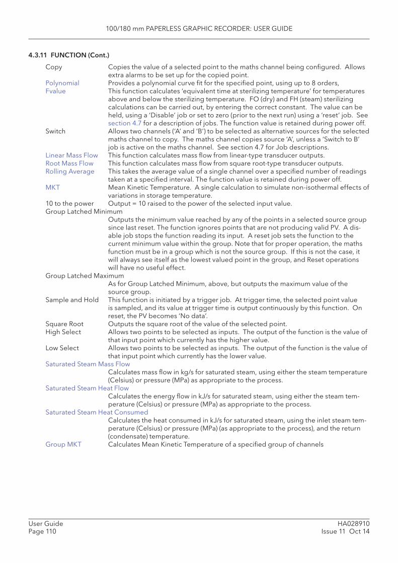
100/180 mm PAPERLESS GRAPHIC RECORDER: USER GUIDE
HA028910Issue 11 Oct 14
User GuidePage 110
4.3.11 FUNCTION (Cont.)
Copy Copies the value of a selected point to the maths channel being confi gured. Allows extra alarms to be set up for the copied point.
Polynomial Provides a polynomial curve fi t for the specifi ed point, using up to 8 orders, Fvalue This function calculates ‘equivalent time at sterilizing temperature’ for temperatures
above and below the sterilizing temperature. FO (dry) and FH (steam) sterilizing calculations can be carried out, by entering the correct constant. The value can be held, using a ‘Disable’ job or set to zero (prior to the next run) using a ‘reset’ job. See section 4.7 for a description of jobs. The function value is retained during power off.
Switch Allows two channels (‘A’ and ‘B’) to be selected as alternative sources for the selected maths channel to copy. The maths channel copies source ‘A’, unless a ‘Switch to B’ job is active on the maths channel. See section 4.7 for Job descriptions.
Linear Mass Flow This function calculates mass fl ow from linear-type transducer outputs.Root Mass Flow This function calculates mass fl ow from square root-type transducer outputs. Rolling Average This takes the average value of a single channel over a specifi ed number of readings
taken at a specifi ed interval. The function value is retained during power off.MKT Mean Kinetic Temperature. A single calculation to simulate non-isothermal effects of
variations in storage temperature. 10 to the power Output = 10 raised to the power of the selected input value. Group Latched Minimum
Outputs the minimum value reached by any of the points in a selected source group since last reset. The function ignores points that are not producing valid PV. A dis-able job stops the function reading its input. A reset job sets the function to the current minimum value within the group. Note that for proper operation, the maths function must be in a group which is not the source group. If this is not the case, it will always see itself as the lowest valued point in the group, and Reset operations will have no useful effect.
Group Latched Maximum As for Group Latched Minimum, above, but outputs the maximum value of the source group.
Sample and Hold This function is initiated by a trigger job. At trigger time, the selected point value is sampled, and its value at trigger time is output continuously by this function. On reset, the PV becomes ‘No data’.
Square Root Outputs the square root of the value of the selected point. High Select Allows two points to be selected as inputs. The output of the function is the value of
that input point which currently has the higher value. Low Select Allows two points to be selected as inputs. The output of the function is the value of
that input point which currently has the lower value.Saturated Steam Mass Flow
Calculates mass fl ow in kg/s for saturated steam, using either the steam temperature (Celsius) or pressure (MPa) as appropriate to the process.
Saturated Steam Heat FlowCalculates the energy fl ow in kJ/s for saturated steam, using either the steam tem-perature (Celsius) or pressure (MPa) as appropriate to the process.
Saturated Steam Heat ConsumedCalculates the heat consumed in kJ/s for saturated steam, using the inlet steam tem-perature (Celsius) or pressure (MPa) (as appropriate to the process), and the return (condensate) temperature.
Group MKT Calculates Mean Kinetic Temperature of a specifi ed group of channels

100/180 mm PAPERLESS GRAPHIC RECORDER: USER GUIDE
User GuidePage 111
HA028910Issue 11 Oct 14
4.3.11 FUNCTION (Cont.)
Log Base 10 Takes log10 of selected input. (For example: Input = 2 gives maths function value = 0.3010)
Log Base e Takes loge of selected input. (For example: Input = 2 gives maths function value = 0.6931)
e to the power Takes natural antilog of input. (For example: Input = 0.6931 gives maths function value = 2)
Modulus This function copies the magnitude of the input value, without the sign. For example, the modulus of value +100 = +100; the modulus of -100 = +100.
Channel Maximum Maths function value is the minimum value the input point has reached since last reset. When reset, the value is reset to the current input value.
Channel Minimum Maths function value is the minimum value the input point has reached since last reset. When reset, the value is reset to the current input value.
Channel Average Takes the average value of the selected channel over a specifi ed time period. The time period must be a multiple of 125 msecs. For example, a period of 0.2 seconds would be rejected, but a period of 0.25 seconds would be accepted.
Master comms Allows a maths channel to read point values from other instruments on the Modbus link.
Rate of change Produces a value for the speed at which a signal changes over a specifi ed period. O2 Correction This function carries out O2 correction of gas measurements for use in Continuous
Emissions Monitoring applications.Relative Humidity This uses wet and dry bulb temperatures and atmospheric pressure inputs to pro-
duce a percentage Relative Humidity reading.Zirconia probe Allows oxygen concentration and oxygen potential to be determined by solving the
Nernst oxygen equation. Timestamp When triggered by an event or alarm job, this causes the current number of millisec-
onds since 00:00 hrs on 1st January 1970 to appear as the function value. If the se-lected PV format is date or time, the result is displayed as date or time, respectively.
Confi g Revision Number*Allows the Confi guration Revision number to be used as the input to a maths chan-nel. When this maths channel is included in a group, the user can determine the Confi guration Revision number obtaining at any time in the history record.
Security Revision Number*Allows the Security Revision number to be used as the input to a maths channel. When this maths channel is included in a group, the user can determine the Security Revision number obtaining at any time in the history record.
*Note: See ‘About’ in section 4.6 for a description of the Confi guration and Security Revision num-bers.
Thermocouple Cal CorrectionDefi nes correction points allowing offsets to be added to channel inputs to compen-sate (for example) for equipment errors.
SCALE LOW / SCALE HIGH
The ‘zero’ and full scale values for the maths function, as displayed. If A/B switching is enabled, a second set of scale low and scale high values can be entered. ‘A’ values are used during normal operation. ‘B’ values are switched to by job action, as described in section 4.7.
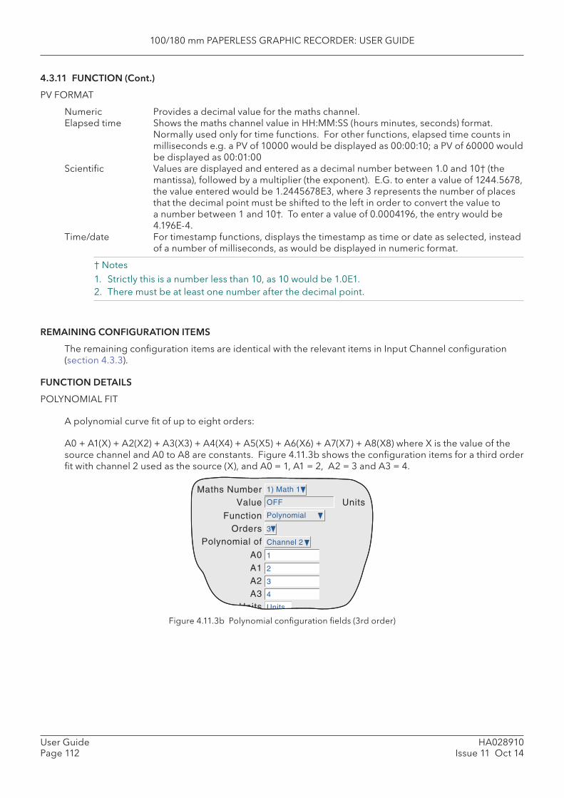
100/180 mm PAPERLESS GRAPHIC RECORDER: USER GUIDE
HA028910Issue 11 Oct 14
User GuidePage 112
4.3.11 FUNCTION (Cont.)
PV FORMAT
Numeric Provides a decimal value for the maths channel. Elapsed time Shows the maths channel value in HH:MM:SS (hours minutes, seconds) format.
Normally used only for time functions. For other functions, elapsed time counts in milliseconds e.g. a PV of 10000 would be displayed as 00:00:10; a PV of 60000 would be displayed as 00:01:00
Scientifi c Values are displayed and entered as a decimal number between 1.0 and 10† (the mantissa), followed by a multiplier (the exponent). E.G. to enter a value of 1244.5678, the value entered would be 1.2445678E3, where 3 represents the number of places that the decimal point must be shifted to the left in order to convert the value to a number between 1 and 10†. To enter a value of 0.0004196, the entry would be 4.196E-4.
Time/date For timestamp functions, displays the timestamp as time or date as selected, instead of a number of milliseconds, as would be displayed in numeric format.
† Notes 1. Strictly this is a number less than 10, as 10 would be 1.0E1.2. There must be at least one number after the decimal point.
REMAINING CONFIGURATION ITEMS
The remaining confi guration items are identical with the relevant items in Input Channel confi guration (section 4.3.3).
FUNCTION DETAILS
POLYNOMIAL FIT
A polynomial curve fi t of up to eight orders:
A0 + A1(X) + A2(X2) + A3(X3) + A4(X4) + A5(X5) + A6(X6) + A7(X7) + A8(X8) where X is the value of the source channel and A0 to A8 are constants. Figure 4.11.3b shows the confi guration items for a third order fi t with channel 2 used as the source (X), and A0 = 1, A1 = 2, A2 = 3 and A3 = 4.
Figure 4.11.3b Polynomial confi guration fi elds (3rd order)
Function Polynomial
OrdersPolynomial of
A0Math 1
0
1
3
1
Maths Number 1) Math 1
Value OFF
Channel 2
A1 2
A2 3
A3 4
Units
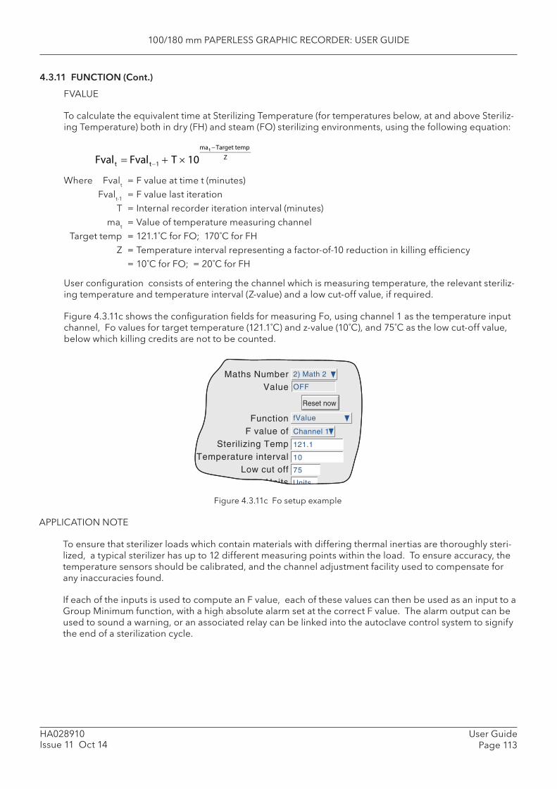
100/180 mm PAPERLESS GRAPHIC RECORDER: USER GUIDE
User GuidePage 113
HA028910Issue 11 Oct 14
4.3.11 FUNCTION (Cont.)
FVALUE
To calculate the equivalent time at Sterilizing Temperature (for temperatures below, at and above Steriliz-ing Temperature) both in dry (FH) and steam (FO) sterilizing environments, using the following equation:
Fvalt Fvalt1 T 10ma t Target temp
Z
Where Fvalt = F value at time t (minutes) Fvalt-1 = F value last iteration T = Internal recorder iteration interval (minutes) mat = Value of temperature measuring channel Target temp = 121.1˚C for FO; 170˚C for FH Z = Temperature interval representing a factor-of-10 reduction in killing effi ciency = 10˚C for FO; = 20˚C for FH
User confi guration consists of entering the channel which is measuring temperature, the relevant steriliz-ing temperature and temperature interval (Z-value) and a low cut-off value, if required.
Figure 4.3.11c shows the confi guration fi elds for measuring Fo, using channel 1 as the temperature input channel, Fo values for target temperature (121.1˚C) and z-value (10˚C), and 75˚C as the low cut-off value, below which killing credits are not to be counted.
Figure 4.3.11c Fo setup example
APPLICATION NOTE
To ensure that sterilizer loads which contain materials with differing thermal inertias are thoroughly steri-lized, a typical sterilizer has up to 12 different measuring points within the load. To ensure accuracy, the temperature sensors should be calibrated, and the channel adjustment facility used to compensate for any inaccuracies found.
If each of the inputs is used to compute an F value, each of these values can then be used as an input to a Group Minimum function, with a high absolute alarm set at the correct F value. The alarm output can be used to sound a warning, or an associated relay can be linked into the autoclave control system to signify the end of a sterilization cycle.
Function fValue
F value ofSterilizing Temp 121.1
Temperature intervalLow cut off
Channel 1
75
Maths Number 2) Math 2
Value OFF
Reset now
10

100/180 mm PAPERLESS GRAPHIC RECORDER: USER GUIDE
HA028910Issue 11 Oct 14
User GuidePage 114
4.3.11 FUNCTION (Cont.)
LINEAR MASS FLOW
Note: The overall accuracy of a fl ow measurement installation depends on a number of factors outside the control of the recorder manufacturer. For this reason, the recorder manufacturer takes no responsibility for the accuracy of the results obtained using the mass fl ow equations imple-mented in the maths pack.
The equations solved is:
where, QMt = Mass fl ow (in kg/sec), at time ‘t’ K = Scaling factor (see below) Rg = Specifi c gas constant in J/kg-K (see below) Z = Compressibility factor (see below) Flowt = Measured value from the fl ow meter at time ‘t’ AbsPt = Absolute pressure of the fl uid at time ‘t’ in kPa(A) Temp = Temperature of the fl uid in Kelvins
Scaling factor This is determined from an assumed value of Qm at a known Flow, AbsP and Temp. The value is chosen to give an output within the range low scale to high scale.
Specifi c gas constant The specifi c gas constant for any gas is available from published tables. For conven-ience, the value for a number of common gases is given in table 4.3.11a, below.
QM t
KRg Z
Flowt AbsPt
Temp
Table 4.3.11a Common gas constants
AirAmmoniaCarbon dioxideCarbon monoxideEthyleneHydrogenMethaneNitrogenOxygenPropaneSteam
287.1488.2188.9296.8296.4
4116.0518.4296.8259.8188.5461.4
RG(J/kg-K)
Gas
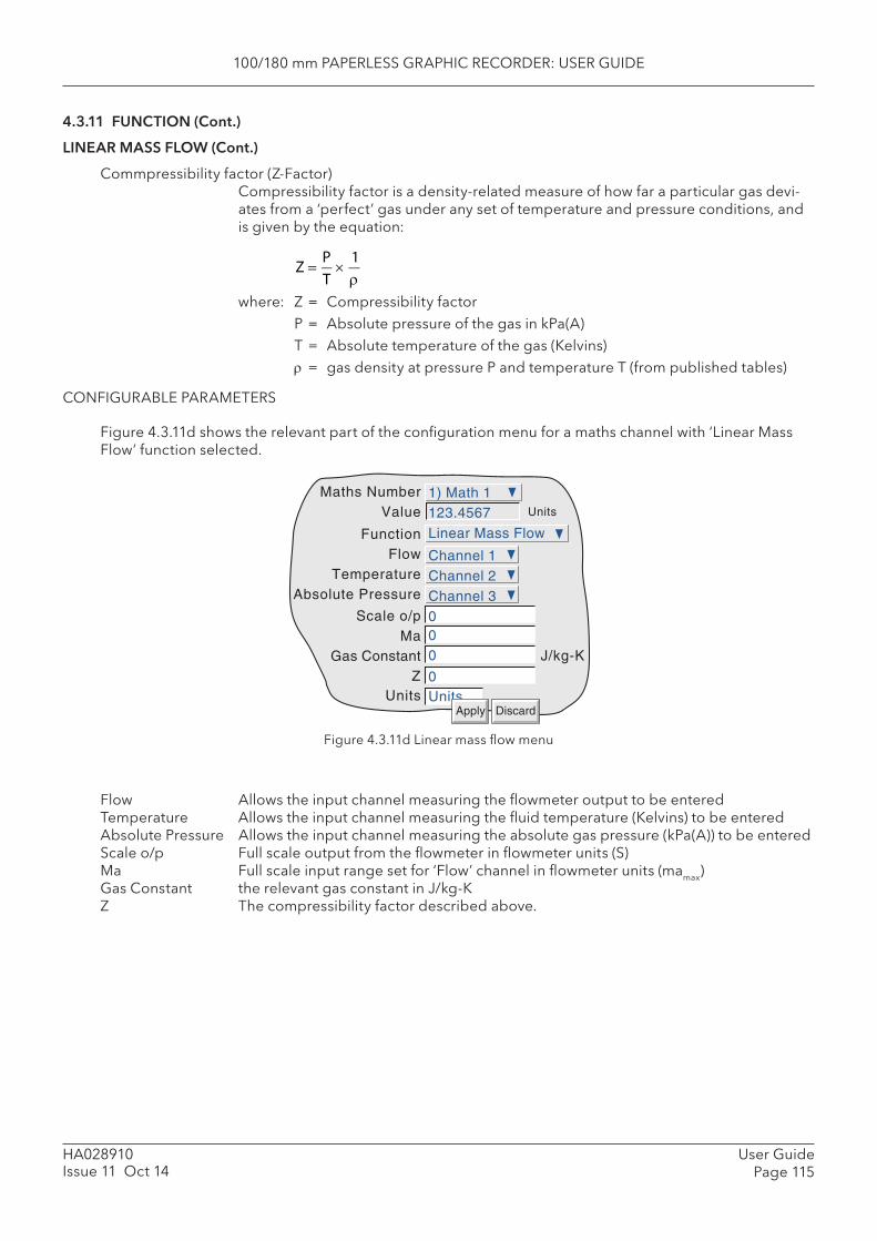
100/180 mm PAPERLESS GRAPHIC RECORDER: USER GUIDE
User GuidePage 115
HA028910Issue 11 Oct 14
4.3.11 FUNCTION (Cont.)
LINEAR MASS FLOW (Cont.)
Commpressibility factor ( Z-Factor)Compressibility factor is a density-related measure of how far a particular gas devi-ates from a ‘perfect’ gas under any set of temperature and pressure conditions, and is given by the equation:
where: Z = Compressibility factor P = Absolute pressure of the gas in kPa(A) T = Absolute temperature of the gas (Kelvins) = gas density at pressure P and temperature T (from published tables)
CONFIGURABLE PARAMETERS
Figure 4.3.11d shows the relevant part of the confi guration menu for a maths channel with ‘Linear Mass Flow’ function selected.
Z
PT
1
Figure 4.3.11d Linear mass fl ow menu
Flow Allows the input channel measuring the fl owmeter output to be enteredTemperature Allows the input channel measuring the fl uid temperature (Kelvins) to be enteredAbsolute Pressure Allows the input channel measuring the absolute gas pressure (kPa(A)) to be enteredScale o/p Full scale output from the fl owmeter in fl owmeter units (S)Ma Full scale input range set for ‘Flow’ channel in fl owmeter units (mamax)Gas Constant the relevant gas constant in J/kg-KZ The compressibility factor described above.
Function Linear Mass Flow
FlowTemperature
Absolute Pressure
Scale o/p0Ma0Gas Constant
0ZUnits
Channel 1
0
Units
Maths Number 1) Math 1Value 123.4567
Channel 2Channel 3
Units
Apply Discard
J/kg-K

100/180 mm PAPERLESS GRAPHIC RECORDER: USER GUIDE
HA028910Issue 11 Oct 14
User GuidePage 116
4.3.11 FUNCTION (Cont.)
ROOT MASS FLOW
Note: The overall accuracy of a fl ow measurement installation depends on a number of factors outside the control of the recorder manufacturer. For this reason, the recorder manufacturer takes no responsibility for the accuracy of the results obtained using the mass fl ow equations imple-mented in the maths pack.
The equation solved is:
where QMt = Mass fl ow (in kg/sec), at time ‘t’ K = Scaling factor (see below) Rg = Specifi c gas constant in J/kg-K (see below) Z = Compressibility factor (see below) DeltaPt = Measured value across the orifi ce plate at time ‘t’ AbsPt = Absolute pressure of the fl uid at the up-stream tapping at time ‘t’ in kPa(A) Temp = Temperature of the fl uid at the up-stream tapping in Kelvins
Scaling factor This is determined from an assumed value of Qm at a known DeltaP, AbsP and Temp. The value is chosen to give an output within the range low scale to high scale.
Specifi c gas constant The specifi c gas constant for any gas is available from published tables. For conven-ience, the value for a number of common gases is given in table 4.3.11a, above.
Compressibility factor (Z-Factor) Compressibility factor is a density-related measure of how far a particular gas devi-
ates from a ‘perfect’ gas under any set of temperature and pressure conditions, and is given by the equation:
where: Z = Compressibility factor P = Absolute pressure of the gas in kPa(A) T = Absolute temperature of the gas (Kelvins) = gas density at pressure P and temperature T (from published tables
QM t
K 2
Rg Z
DeltaPt AbsPt
Temp
Z
PT
1
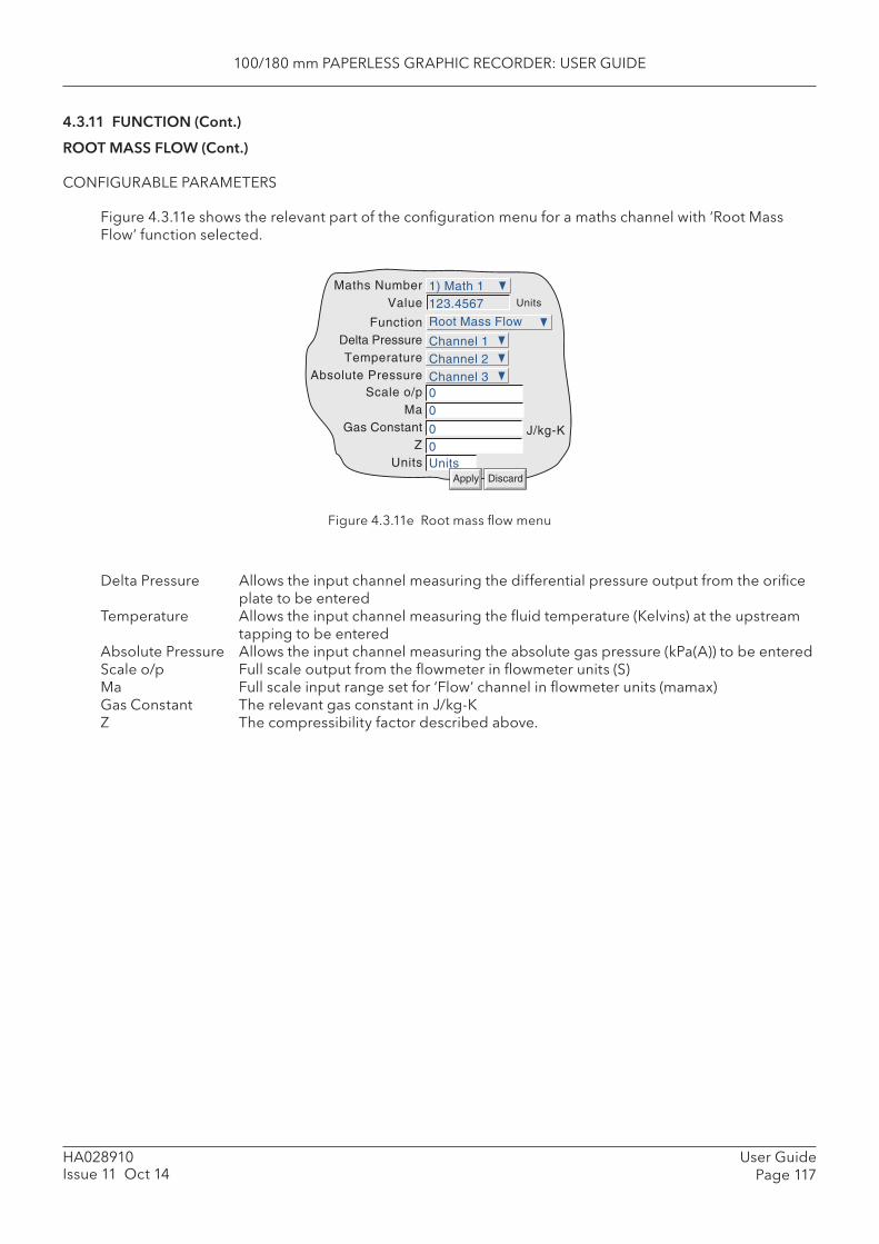
100/180 mm PAPERLESS GRAPHIC RECORDER: USER GUIDE
User GuidePage 117
HA028910Issue 11 Oct 14
4.3.11 FUNCTION (Cont.)
ROOT MASS FLOW (Cont.)
CONFIGURABLE PARAMETERS
Figure 4.3.11e shows the relevant part of the confi guration menu for a maths channel with ‘Root Mass Flow’ function selected.
Figure 4.3.11e Root mass fl ow menu
Delta Pressure Allows the input channel measuring the differential pressure output from the orifi ce plate to be entered
Temperature Allows the input channel measuring the fl uid temperature (Kelvins) at the upstream tapping to be entered
Absolute Pressure Allows the input channel measuring the absolute gas pressure (kPa(A)) to be enteredScale o/p Full scale output from the fl owmeter in fl owmeter units (S)Ma Full scale input range set for ‘Flow’ channel in fl owmeter units (mamax)Gas Constant The relevant gas constant in J/kg-KZ The compressibility factor described above.
FunctionDelta PressureTemperature
Absolute PressureScale o/p
MaGas Constant
ZUnits
Maths NumberValue Units
J/kg-K
Apply Discard
Root Mass Flow
00
00
Channel 1
Units
1) Math 1123.4567
Channel 2Channel 3
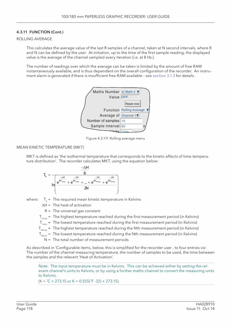
100/180 mm PAPERLESS GRAPHIC RECORDER: USER GUIDE
HA028910Issue 11 Oct 14
User GuidePage 118
4.3.11 FUNCTION (Cont.)
ROLLING AVERAGE
This calculates the average value of the last R samples of a channel, taken at N second intervals, where R and N can be defi ned by the user. At initiation, up to the time of the fi rst sample reading, the displayed value is the average of the channel sampled every iteration (i.e. at 8 Hz.).
The number of readings over which the average can be taken is limited by the amount of free RAM instantaneously available, and is thus dependent on the overall confi guration of the recorder. An instru-ment alarm is generated if there is insuffi cient free RAM available - see section 3.1.3 for details.
Figure 4.3.11f Rolling average menu
MEAN KINETIC TEMPERATURE (MKT)
MKT is defi ned as ‘the isothermal temperature that corresponds to the kinetic effects of time-tempera-ture distribution’. The recorder calculates MKT, using the equation below:
Function Rolling Average
Average ofNumber of samples 10
Sample Interval
Channel 1
Maths Number 4) Math 4
Value OFF
Reset now
60 s
Tk
HR
lne
HRT1max e
HRT1min ... e
HRTNmax e
HRTNmax
2N
where: Tk = The required mean kinetic temperature in Kelvins H = The heat of activation R = The universal gas constant T1max = The highest temperature reached during the fi rst measurement period (in Kelvins) T1min = The lowest temperature reached during the fi rst measurement period (in Kelvins) TNmax = The highest temperature reached during the Nth measurement period (in Kelvins) TNmin = The lowest temperature reached during the Nth measurement period (in Kelvins) N = The total number of measurement periods
As described in ‘Confi gurable items, below, this is simplifi ed for the recorder user , to four entries viz: The number of the channel measuring temperature, the number of samples to be used, the time between the samples and the relevant ‘Heat of Activation’.
Note: The input temperature must be in Kelvins. This can be achieved either by setting the rel-evant channel’s units to Kelvins, or by using a further maths channel to convert the measuring units to Kelvins. (K = ˚C + 273.15 or K = 0.555(˚F -32) + 273.15).
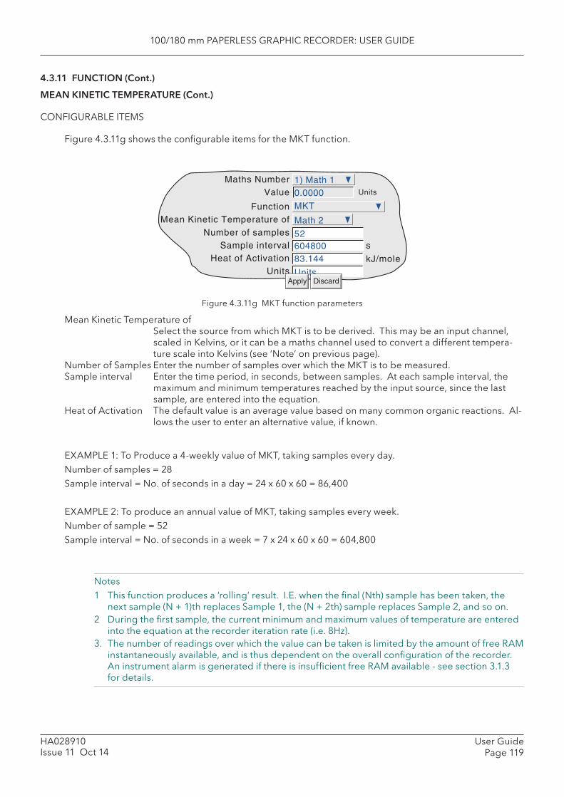
100/180 mm PAPERLESS GRAPHIC RECORDER: USER GUIDE
User GuidePage 119
HA028910Issue 11 Oct 14
4.3.11 FUNCTION (Cont.)
MEAN KINETIC TEMPERATURE (Cont.)
CONFIGURABLE ITEMS
Figure 4.3.11g shows the confi gurable items for the MKT function.
Figure 4.3.11g MKT function parameters
Mean Kinetic Temperature ofSelect the source from which MKT is to be derived. This may be an input channel, scaled in Kelvins, or it can be a maths channel used to convert a different tempera-ture scale into Kelvins (see ‘Note’ on previous page).
Number of Samples Enter the number of samples over which the MKT is to be measured.Sample interval Enter the time period, in seconds, between samples. At each sample interval, the
maximum and minimum temperatures reached by the input source, since the last sample, are entered into the equation.
Heat of Activation The default value is an average value based on many common organic reactions. Al-lows the user to enter an alternative value, if known.
EXAMPLE 1: To Produce a 4-weekly value of MKT, taking samples every day.Number of samples = 28Sample interval = No. of seconds in a day = 24 x 60 x 60 = 86,400
EXAMPLE 2: To produce an annual value of MKT, taking samples every week.Number of sample = 52Sample interval = No. of seconds in a week = 7 x 24 x 60 x 60 = 604,800
Notes1 This function produces a ‘rolling’ result. I.E. when the fi nal (Nth) sample has been taken, the
next sample (N + 1)th replaces Sample 1, the (N + 2th) sample replaces Sample 2, and so on.2 During the fi rst sample, the current minimum and maximum values of temperature are entered
into the equation at the recorder iteration rate (i.e. 8Hz).3. The number of readings over which the value can be taken is limited by the amount of free RAM
instantaneously available, and is thus dependent on the overall confi guration of the recorder. An instrument alarm is generated if there is insuffi cient free RAM available - see section 3.1.3 for details.
Function MKT
Mean Kinetic Temperature ofNumber of samples
Sample interval 604800Heat of Activation 83.144
Units Units
Math 2
52
Maths Number 1) Math 1Value 0.0000 Units
kJ/mole
s
Apply Discard
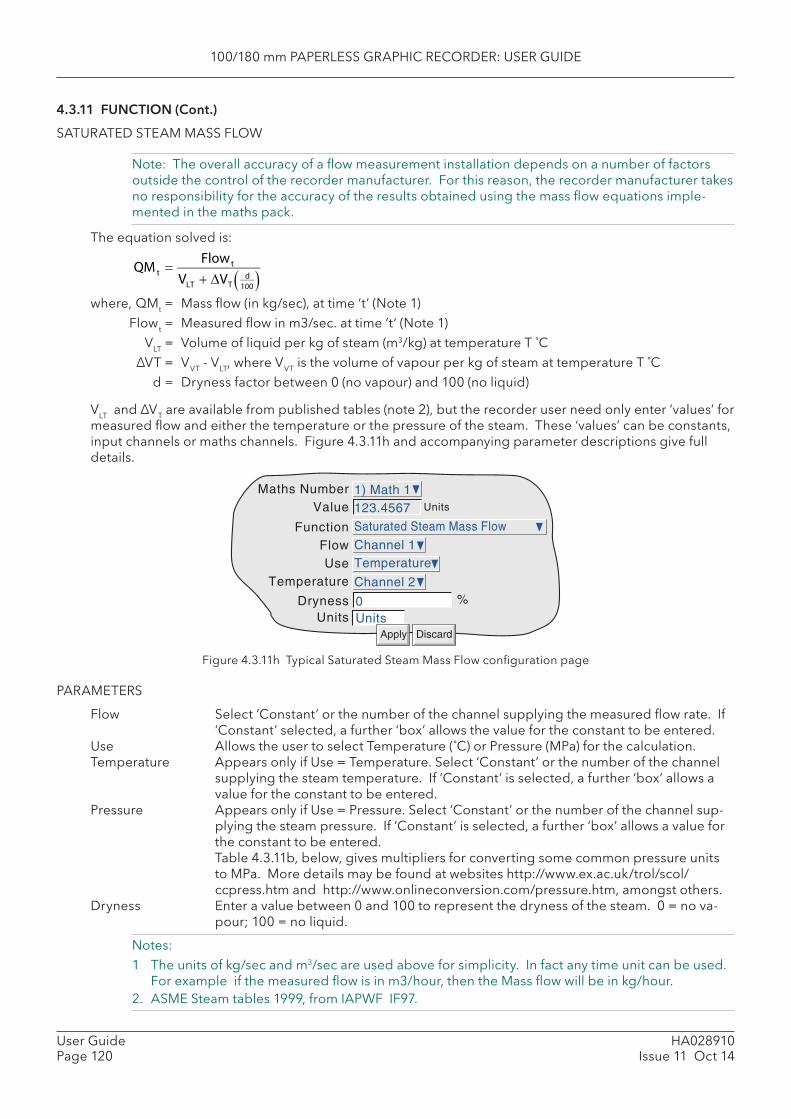
100/180 mm PAPERLESS GRAPHIC RECORDER: USER GUIDE
HA028910Issue 11 Oct 14
User GuidePage 120
4.3.11 FUNCTION (Cont.)
SATURATED STEAM MASS FLOW
Note: The overall accuracy of a fl ow measurement installation depends on a number of factors outside the control of the recorder manufacturer. For this reason, the recorder manufacturer takes no responsibility for the accuracy of the results obtained using the mass fl ow equations imple-mented in the maths pack.
The equation solved is:
where, QMt = Mass fl ow (in kg/sec), at time ‘t’ (Note 1) Flowt = Measured fl ow in m3/sec. at time ‘t’ (Note 1) VLT = Volume of liquid per kg of steam (m3/kg) at temperature T ˚C ΔVT = VVT - VLT, where VVT is the volume of vapour per kg of steam at temperature T ˚C d = Dryness factor between 0 (no vapour) and 100 (no liquid)
VLT and ΔVT are available from published tables (note 2), but the recorder user need only enter ‘values’ for measured fl ow and either the temperature or the pressure of the steam. These ‘values’ can be constants, input channels or maths channels. Figure 4.3.11h and accompanying parameter descriptions give full details.
QM t
Flowt
VLT VTd
100
FunctionFlowUse
Temperature
DrynessUnits
Maths NumberValue Units
Apply Discard
%
Saturated Steam Mass Flow
Channel 1
0Units
1) Math 1123.4567
Temperature
Channel 2
Figure 4.3.11h Typical Saturated Steam Mass Flow confi guration page
PARAMETERS
Flow Select ‘Constant’ or the number of the channel supplying the measured fl ow rate. If ‘Constant’ selected, a further ‘box’ allows the value for the constant to be entered.
Use Allows the user to select Temperature (˚C) or Pressure (MPa) for the calculation. Temperature Appears only if Use = Temperature. Select ‘Constant’ or the number of the channel
supplying the steam temperature. If ‘Constant’ is selected, a further ‘box’ allows a value for the constant to be entered.
Pressure Appears only if Use = Pressure. Select ‘Constant’ or the number of the channel sup-plying the steam pressure. If ‘Constant’ is selected, a further ‘box’ allows a value for the constant to be entered.
Table 4.3.11b, below, gives multipliers for converting some common pressure units to MPa. More details may be found at websites http://www.ex.ac.uk/trol/scol/ccpress.htm and http://www.onlineconversion.com/pressure.htm, amongst others.
Dryness Enter a value between 0 and 100 to represent the dryness of the steam. 0 = no va-pour; 100 = no liquid.
Notes:1 The units of kg/sec and m3/sec are used above for simplicity. In fact any time unit can be used.
For example if the measured fl ow is in m3/hour, then the Mass fl ow will be in kg/hour.2. ASME Steam tables 1999, from IAPWF IF97.

100/180 mm PAPERLESS GRAPHIC RECORDER: USER GUIDE
User GuidePage 121
HA028910Issue 11 Oct 14
4.3.11 FUNCTION (Cont.)
SATURATED STEAM MASS FLOW (Cont.)
PRESSURE UNITS CONVERSION
There is a wide range of pressure measuring units in use throughout the world. The following table gives a multiplication factor for converting some common units to MPa (MegaPascals), to four signifi cant fi gures. Further conversion factors can be found at the websites given on the previous page. (Where the conversion is to Pascals, not to MegaPascals, the factors given have to be divided by 1,000,000.)
Table 4.3.11b Pressure unit conversion
The table above shows multiplying factors to convert common pressure units to MPa. This conversion is carried out as follows:
Example: A pressure transducer, connected to input channel 3 gives an output in the range 10 to 100 PSI. The input to a steam equation in maths channel 1 requires the pressure units to be MPa. To convert, set up a further maths channel (e.g. No. 2) as shown below, then use maths channel 2 as the source channel for the pressure input to the steam equation.
The suggested scale low/high values are based on the resulting pressure range in MPa - i.e 0.06895 to 0.6895.
Figure 4.3.11i PSI to MPa conversion example
Pressure units Multiplier forMPa
Atmospheres 0.1013Bar 0.1
kg/cm2 0.09 807kNewton/m2 0.001kPa 0.001mBar 0.0001
Lb/ft2 0.00 004 788Lb/in2 (PSI) 0.006 895Mercury (inches of) 0.003 386Mercury (mm of) 0.0 001 333
Newtons/cm2 0.01
Newtons/m2 0.000 001Pascals 0.000 001
Tonnes/m2 0.009 807
Tons(UK)/ft2 0.1 073
Tons(US)/ft2 0.09 576Water (feet of) 0.002 989
Water (inches of) 0.0 002 491
Water (mm of) 0.000 009 807
Pressure units Multiplier forMPa
FunctionMultiply
by
Constant ValueUnits
Maths NumberValue Units
Apply Discard
DescriptorScale low
Scale high
MPa
MPa
Multiply
Channel 3
0.006895MPa
2) Steam Pressure
0.0348
Constant
Steam Pressure0
1
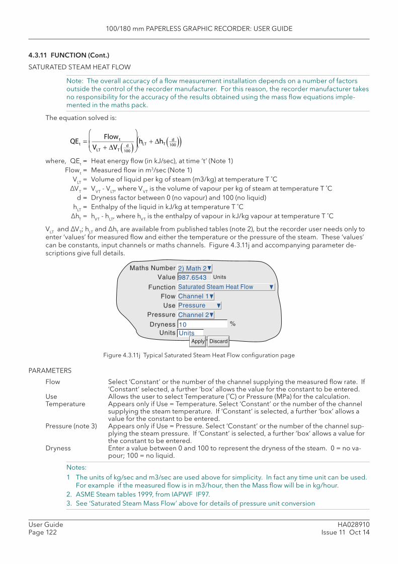
100/180 mm PAPERLESS GRAPHIC RECORDER: USER GUIDE
HA028910Issue 11 Oct 14
User GuidePage 122
4.3.11 FUNCTION (Cont.)
SATURATED STEAM HEAT FLOW
Note: The overall accuracy of a fl ow measurement installation depends on a number of factors outside the control of the recorder manufacturer. For this reason, the recorder manufacturer takes no responsibility for the accuracy of the results obtained using the mass fl ow equations imple-mented in the maths pack.
The equation solved is:
where, QEt = Heat energy fl ow (in kJ/sec), at time ‘t’ (Note 1) Flowt = Measured fl ow in m3/sec (Note 1) VLT = Volume of liquid per kg of steam (m3/kg) at temperature T ˚C ΔVT = VVT - VLT, where VVT is the volume of vapour per kg of steam at temperature T ˚C d = Dryness factor between 0 (no vapour) and 100 (no liquid) hLT = Enthalpy of the liquid in kJ/kg at temperature T ˚C ΔhT = hVT - hLT, where hVT is the enthalpy of vapour in kJ/kg vapour at temperature T ˚C
VLT and ΔVT; hLT and ΔhT are available from published tables (note 2), but the recorder user needs only to enter ‘values’ for measured fl ow and either the temperature or the pressure of the steam. These ‘values’ can be constants, input channels or maths channels. Figure 4.3.11j and accompanying parameter de-scriptions give full details.
QEt
Flowt
VLT VTd
100
hLT hT
d100
Figure 4.3.11j Typical Saturated Steam Heat Flow confi guration page
PARAMETERS
Flow Select ‘Constant’ or the number of the channel supplying the measured fl ow rate. If ‘Constant’ selected, a further ‘box’ allows the value for the constant to be entered.
Use Allows the user to select Temperature (˚C) or Pressure (MPa) for the calculation.Temperature Appears only if Use = Temperature. Select ‘Constant’ or the number of the channel
supplying the steam temperature. If ‘Constant’ is selected, a further ‘box’ allows a value for the constant to be entered.
Pressure (note 3) Appears only if Use = Pressure. Select ‘Constant’ or the number of the channel sup-plying the steam pressure. If ‘Constant’ is selected, a further ‘box’ allows a value for the constant to be entered.
Dryness Enter a value between 0 and 100 to represent the dryness of the steam. 0 = no va-pour; 100 = no liquid.
Notes:1 The units of kg/sec and m3/sec are used above for simplicity. In fact any time unit can be used.
For example if the measured fl ow is in m3/hour, then the Mass fl ow will be in kg/hour.2. ASME Steam tables 1999, from IAPWF IF97.3. See ‘Saturated Steam Mass Flow’ above for details of pressure unit conversion
FunctionFlowUse
Pressure
DrynessUnits
Maths NumberValue Units
Apply Discard
%
Saturated Steam Heat Flow
Channel 1
10Units
2) Math 2987.6543
Pressure
Channel 2
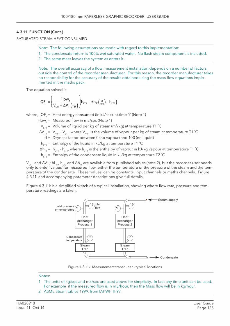
100/180 mm PAPERLESS GRAPHIC RECORDER: USER GUIDE
User GuidePage 123
HA028910Issue 11 Oct 14
4.3.11 FUNCTION (Cont.)
SATURATED STEAM HEAT CONSUMED
Note: The following assumptions are made with regard to this implementation:1. The condensate return is 100% wet saturated water. No fl ash steam component is included.2. The same mass leaves the system as enters it.
Note: The overall accuracy of a fl ow measurement installation depends on a number of factors outside the control of the recorder manufacturer. For this reason, the recorder manufacturer takes no responsibility for the accuracy of the results obtained using the mass fl ow equations imple-mented in the maths pack.
The equation solved is:
where, QEt = Heat energy consumed (in kJ/sec), at time ‘t’ (Note 1) Flowt = Measured fl ow in m3/sec (Note 1) VLT1 = Volume of liquid per kg of steam (m3/kg) at temperature T1 ˚C ΔVT1 = VVT1 - VLT1, where VVT1 is the volume of vapour per kg of steam at temperature T1 ˚C d = Dryness factor between 0 (no vapour) and 100 (no liquid) hLT1 = Enthalpy of the liquid in kJ/kg at temperature T1 ˚C ΔhT1 = hVT1 - hLT1, where hVT1 is the enthalpy of vapour in kJ/kg vapour at temperature T1 ˚C hLT2 = Enthalpy of the condensate liquid in kJ/kg at temperature T2 ˚C
VLT1 and ΔVT1; hLT1, hLT2 and ΔhT1 are available from published tables (note 2), but the recorder user needs only to enter ‘values’ for measured fl ow, either the temperature or the pressure of the steam and the tem-perature of the condensate. These ‘values’ can be constants, input channels or maths channels. Figure 4.3.11l and accompanying parameter descriptions give full details.
Figure 4.3.11k is a simplifi ed sketch of a typical installation, showing where fl ow rate, pressure and tem-perature readings are taken.
QEt
Flowt
VLT1 VT1d
100
hLT1 hT1
d100 hLT 2
Figure 4.3.11k Measurement transducer - typical locations
Notes:1 The units of kg/sec and m3/sec are used above for simplicity. In fact any time unit can be used.
For example if the measured fl ow is in m3/hour, then the Mass fl ow will be in kg/hour.2. ASME Steam tables 1999, from IAPWF IF97.
Inlet pressureor temperature
Inletflow
Steam supply
Condensate
SteamTrap
HeatexchangerProcess 2
SteamTrap
HeatexchangerProcess 1
Condensatetemperature
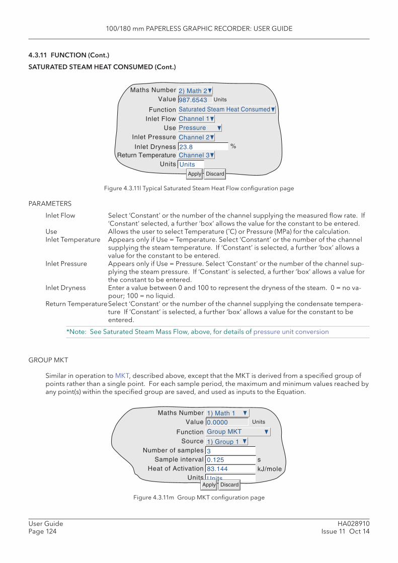
100/180 mm PAPERLESS GRAPHIC RECORDER: USER GUIDE
HA028910Issue 11 Oct 14
User GuidePage 124
4.3.11 FUNCTION (Cont.)
SATURATED STEAM HEAT CONSUMED (Cont.)
Figure 4.3.11l Typical Saturated Steam Heat Flow confi guration page
PARAMETERS
Inlet Flow Select ‘Constant’ or the number of the channel supplying the measured fl ow rate. If ‘Constant’ selected, a further ‘box’ allows the value for the constant to be entered.
Use Allows the user to select Temperature (˚C) or Pressure (MPa) for the calculation.Inlet Temperature Appears only if Use = Temperature. Select ‘Constant’ or the number of the channel
supplying the steam temperature. If ‘Constant’ is selected, a further ‘box’ allows a value for the constant to be entered.
Inlet Pressure Appears only if Use = Pressure. Select ‘Constant’ or the number of the channel sup-plying the steam pressure. If ‘Constant’ is selected, a further ‘box’ allows a value for the constant to be entered.
Inlet Dryness Enter a value between 0 and 100 to represent the dryness of the steam. 0 = no va-pour; 100 = no liquid.
Return Temperature Select ‘Constant’ or the number of the channel supplying the condensate tempera-ture If ‘Constant’ is selected, a further ‘box’ allows a value for the constant to be entered.
*Note: See Saturated Steam Mass Flow, above, for details of pressure unit conversion
GROUP MKT
Similar in operation to MKT, described above, except that the MKT is derived from a specifi ed group of points rather than a single point. For each sample period, the maximum and minimum values reached by any point(s) within the specifi ed group are saved, and used as inputs to the Equation.
Figure 4.3.11m Group MKT confi guration page
Function Saturated Steam Heat Consumed
Inlet FlowUse
Inlet Pressure
Inlet DrynessReturn Temperature
Channel 1
23.8
Maths Number 2) Math 2Value 987.6543
Pressure
Channel 2
Units
Apply Discard
%
Units Units
Channel 3
Function Group MKT
SourceNumber of samples
Sample interval 0.125Heat of Activation 83.144
Units Units
1) Group 1
3
Maths Number 1) Math 1Value 0.0000 Units
kJ/mole
s
Apply Discard
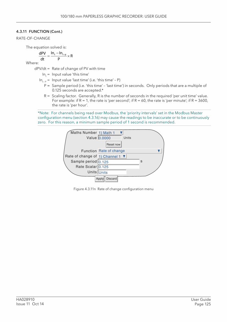
100/180 mm PAPERLESS GRAPHIC RECORDER: USER GUIDE
User GuidePage 125
HA028910Issue 11 Oct 14
4.3.11 FUNCTION (Cont.)
RATE-OF-CHANGE
The equation solved is:
Where: dPV/dt = Rate of change of PV with time Int = Input value ‘this time’ Int - P = Input value ‘last time’ (i.e. ‘this time’ – P) P = Sample period (i.e. ‘this time’ – ‘last time’) in seconds. Only periods that are a multiple of
0.125 seconds are accepted.* R = Scaling factor. Generally, R is the number of seconds in the required ‘per unit time’ value.
For example: if R = 1, the rate is ‘per second’; if R = 60, the rate is ‘per minute’; if R = 3600, the rate is ‘per hour’.
*Note: For channels being read over Modbus, the ‘priority intervals’ set in the Modbus Master confi guration menu (section 4.3.16) may cause the readings to be inaccurate or to be continuously zero. For this reason, a minimum sample period of 1 second is recommended.
Figure 4.3.11n Rate of change confi guration menu
FunctionRate of change of
Sample periodRate Scalar
Units
Maths NumberValue Units
s
Apply Discard
Reset now
Rate of change
0.125
Units
1) Channel 1
0.125
1) Math 10.0000
dPVdt
Int Intp
PR
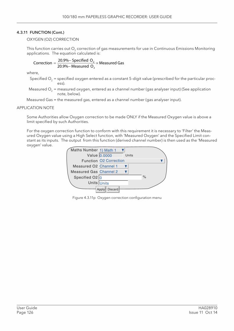
100/180 mm PAPERLESS GRAPHIC RECORDER: USER GUIDE
HA028910Issue 11 Oct 14
User GuidePage 126
4.3.11 FUNCTION (Cont.)
OXYGEN (O2) CORRECTION
This function carries out O2 correction of gas measurements for use in Continuous Emissions Monitoring applications. The equation calculated is:
where, Specifi ed O2 = specifi ed oxygen entered as a constant 5-digit value (prescribed for the particular proc-
ess). Measured O2 = measured oxygen, entered as a channel number (gas analyser input) (See application
note, below). Measured Gas = the measured gas, entered as a channel number (gas analyser input).
APPLICATION NOTE
Some Authorities allow Oxygen correction to be made ONLY if the Measured Oxygen value is above a limit specifi ed by such Authorities.
For the oxygen correction function to conform with this requirement it is necessary to ‘Filter’ the Meas-ured Oxygen value using a High Select function, with ‘Measured Oxygen’ and the Specifi ed Limit con-stant as its inputs. The output from this function (derived channel number) is then used as the ‘ Measured oxygen’ value.
Figure 4.3.11p Oxygen correction confi guration menu
Correction
20.9% Specified O2
20.9%Measured O2
Measured Gas
FunctionMeasured O2
Specified O2Units
Maths NumberValue Units
%
Apply Discard
Measured Gas
O2 Correction
Units
Channel 1
0
1) Math 10.0000
Channel 2
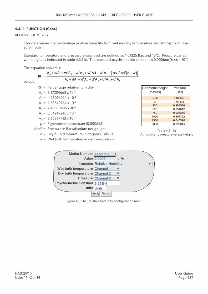
100/180 mm PAPERLESS GRAPHIC RECORDER: USER GUIDE
User GuidePage 127
HA028910Issue 11 Oct 14
4.3.11 FUNCTION (Cont.)
RELATIVE HUMIDITY
This determines the percentage relative humidity from wet and dry temperature and atmospheric pres-sure inputs.
Standard temperature and pressure at sea level are defi ned as 1.01325 Bar, and 15˚C. Pressure varies with height as indicated in table 4.3.11c. The standard psychrometric constant is 0.000666 (6.66 x 10⁻⁴).
The equation solved is:
Where: RH = Percentage relative humidity A0 = 6.17204663 x 10⁻³
A1 = 4.28096024 x 10⁻⁴
A2 = 1.53342964 x 10⁻⁵
A3 = 2.40833685 x 10⁻⁷
A4 = 3.04249240 x 10⁻⁹
A5 = 2.65867713 x 10⁻¹¹
p = Psychrometric constant (0.000666) AbsP = Pressure in Bar (absolute not gauge) d = Dry bulb temperature in degrees Celsius w = Wet bulb temperature in degrees Celsius
RH
A0 wA1 w2A2 w3A3 w4A4 w5A5 p AbsP d w A0 dA1 d2A2 d3A3 d4A4 d5A5
Figure 4.3.11q Relative humidity confi guration menu
Geometric height(metres)
Pressure(Bar)
1.043651.01325
0.9835760.9546120.9263460.8987620.8455960.795014
-2500
250500750
100015002000
Table 4.3.11cAtmospheric pressure versus height
FunctionWet bulb temperatureDry bulb temperature
Pressure
Psychrometric Constant
Maths NumberValue Units
Units
Apply Discard
Relative Humidity
6.66E-4
Channel 1
1) Math 10.0000
Channel 2Channel 3
Units
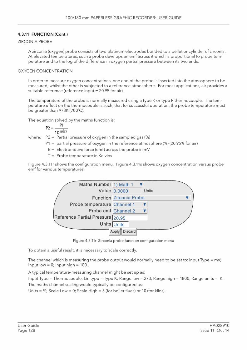
100/180 mm PAPERLESS GRAPHIC RECORDER: USER GUIDE
HA028910Issue 11 Oct 14
User GuidePage 128
4.3.11 FUNCTION (Cont.)
ZIRCONIA PROBE
A zirconia (oxygen) probe consists of two platinum electrodes bonded to a pellet or cylinder of zirconia. At elevated temperatures, such a probe develops an emf across it which is proportional to probe tem-perature and to the log of the difference in oxygen partial pressure between its two ends.
OXYGEN CONCENTRATION
In order to measure oxygen concentrations, one end of the probe is inserted into the atmosphere to be measured, whilst the other is subjected to a reference atmosphere. For most applications, air provides a suitable reference (reference input = 20.95 for air).
The temperature of the probe is normally measured using a type K or type R thermocouple. The tem-perature effect on the thermocouple is such, that for successful operation, the probe temperature must be greater than 973K (700˚C).
The equation solved by the maths function is:
where: P2 = Partial pressure of oxygen in the sampled gas (%) P1 = partial pressure of oxygen in the reference atmosphere (%) (20.95% for air) E = Electromotive force (emf) across the probe in mV T = Probe temperature in Kelvins
Figure 4.3.11r shows the confi guration menu. Figure 4.3.11s shows oxygen concentration versus probe emf for various temperatures.
Figure 4.3.11r Zirconia probe function confi guration menu
To obtain a useful result, it is necessary to scale correctly.
The channel which is measuring the probe output would normally need to be set to: Input Type = mV; Input low = 0; input high = 100..
A typical temperature-measuring channel might be set up as: Input Type = Thermocouple; Lin type = Type K; Range low = 273; Range high = 1800, Range units = K.The maths channel scaling would typically be confi gured as: Units = %; Scale Low = 0; Scale High = 5 (for boiler fl ues) or 10 (for kilns).
FunctionProbe temperature
Probe emfReference Partial Pressure
Maths NumberValue Units
Units
Apply Discard
Zirconia Probe
Channel 1
1) Math 10.0000
Channel 2
Units20.95
P2
P1
10E
0.0496T
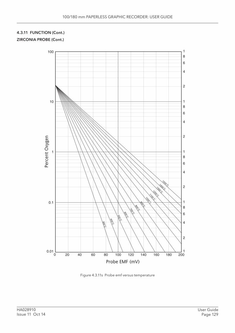
100/180 mm PAPERLESS GRAPHIC RECORDER: USER GUIDE
User GuidePage 129
HA028910Issue 11 Oct 14
4.3.11 FUNCTION (Cont.)
ZIRCONIA PROBE (Cont.)
Figure 4.3.11s Probe emf versus temperature
2001801601401201008060402000.01
0.1
1
10
100 1
8
6
4
2
1
8
6
4
2
1
8
6
4
2
1
8
6
4
2
1
Probe EMF (mV)
Perc
ent
Oxygen
1500˚C1400˚C1300˚C1200˚C1100˚C
900˚C800˚C700˚C600˚C
400˚C
300˚C
500˚C
1000˚C

100/180 mm PAPERLESS GRAPHIC RECORDER: USER GUIDE
HA028910Issue 11 Oct 14
User GuidePage 130
4.3.11 FUNCTION (Cont.)
ZIRCONIA PROBE (Cont.)
OXYGEN POTENTIAL
The oxygen potential of an atmosphere is a measurement of its ability to oxidise or reduce. For any ele-ment, a value of oxygen potential (free energy of formation) is known. Above this value, the material will oxidise, below it, no oxidisation will occur. Figure 4.3.11t, below, is a free energy diagram for a number of oxidising processes.
Oxygen potential is given by the equation
Where: Op = Required oxygen potential (in kilocalories) T = Probe temperature (in Kelvins) Op’ = Partial pressure of oxygen in the reference atmosphere (in atmospheres)
It can be shown that, because the oxygen potential of air is essentially constant over the range 870 to 1450 kelvins, the zirconia probe output is proportional to the oxygen potential of an atmosphere, accord-ing to:
E = (10.84 × T) + 40 mV (in the range 870 to 1450 K)
Thus, it is possible to measure oxygen potential directly from a zirconia probe, using a standard input channel of the instrument, scaled in units of oxygen potential. A typical confi guration might be:
Input Type = mV; Input low = 40; Input high = 1124; Scale low = -100; Scale high = 0; Units = kCal.
Such a confi guration would be suitable over the temperature range 873 to 1473 K (600 to 1200 ˚C).
Op 0.00457 T logO p
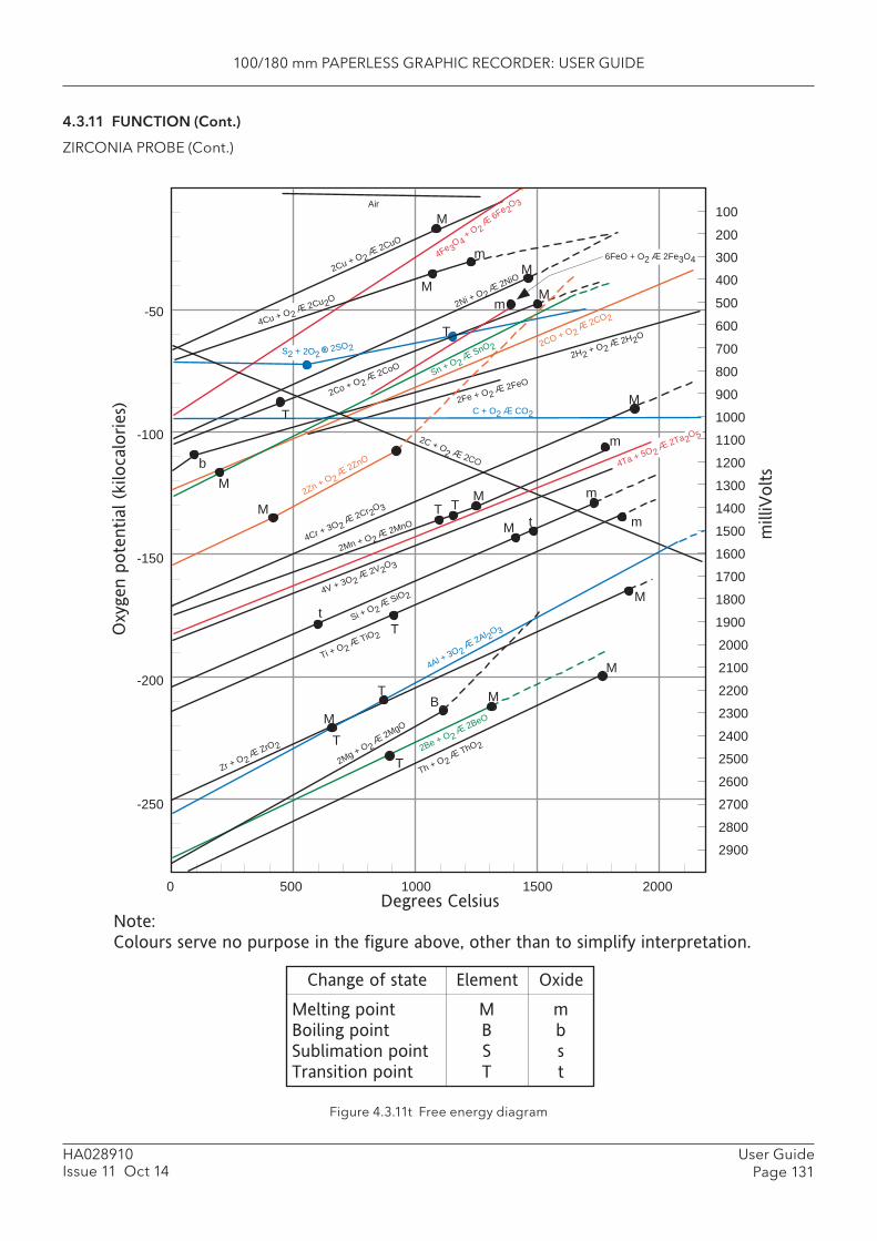
100/180 mm PAPERLESS GRAPHIC RECORDER: USER GUIDE
User GuidePage 131
HA028910Issue 11 Oct 14
4.3.11 FUNCTION (Cont.)
ZIRCONIA PROBE (Cont.)
Figure 4.3.11t Free energy diagram
100
200
300
400
500
600
700
800
900
1000
1100
1200
1300
1400
1500
1600
1700
1800
1900
2000
2100
2200
2300
2400
2500
2600
2700
2800
2900
2Cu + O22CuO
Air
4Fe 3O4 + O 2
6Fe 2O3
M
M
Mm
2Ni + O22NiO
T
T
2Co + O22CoO
bM
Mm
Sn + O 2SnO 2
2Fe + O22FeO
C + O2 CO2
2CO + O22CO2
2H2 + O22H2O
T TM
m
M
MM
M
M
M
MT
T
t
T
m
mt
-50
-100
-150
-200
-250
0 500 1000 1500 2000
B
Degrees Celsius
Oxygen p
ote
ntial (k
ilocalo
ries)
milliV
olt
s
2Zn + O 22ZnO
2C + O2
4Cr + 3O22Cr2O3
2Mn + O22MnO
4V + 3O22V2O3
Si + O 2SiO 2
Ti + O2TiO2 T
4Al + 3O 22Al 2O 3
Zr + O2ZrO 2
2Mg + O 22MgO
2Be + O 22BeO
Th + O 2ThO 2
4Cu + O22Cu2O
6FeO + O2 2Fe3O4
S2 + 2O2 2SO2
4Ta + 5O22Ta2O5
Change of state Element Oxide
Melting point
Boiling point
Sublimation point
Transition point
M
B
S
T
m
b
s
t
Note:
Colours serve no purpose in the figure above, other than to simplify interpretation.
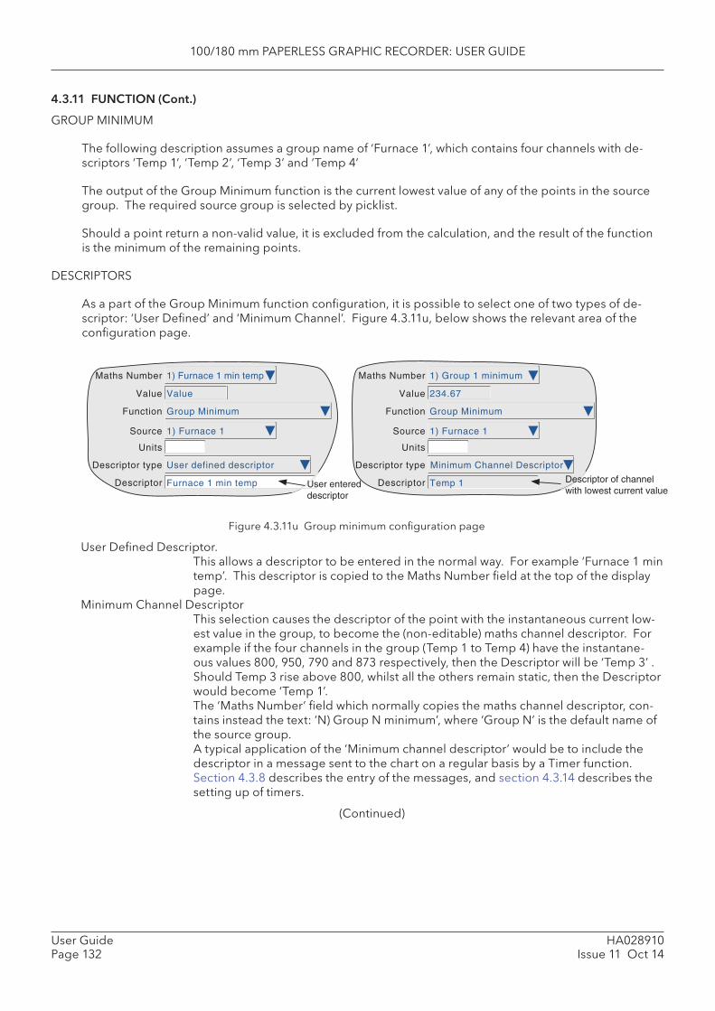
100/180 mm PAPERLESS GRAPHIC RECORDER: USER GUIDE
HA028910Issue 11 Oct 14
User GuidePage 132
4.3.11 FUNCTION (Cont.)
GROUP MINIMUM
The following description assumes a group name of ‘Furnace 1’, which contains four channels with de-scriptors ‘Temp 1’, ‘Temp 2’, ‘Temp 3’ and ‘Temp 4’
The output of the Group Minimum function is the current lowest value of any of the points in the source group. The required source group is selected by picklist.
Should a point return a non-valid value, it is excluded from the calculation, and the result of the function is the minimum of the remaining points.
DESCRIPTORS
As a part of the Group Minimum function confi guration, it is possible to select one of two types of de-scriptor: ‘User Defi ned’ and ‘Minimum Channel’. Figure 4.3.11u, below shows the relevant area of the confi guration page.
Figure 4.3.11u Group minimum confi guration page
User Defi ned Descriptor. This allows a descriptor to be entered in the normal way. For example ‘Furnace 1 min
temp’. This descriptor is copied to the Maths Number fi eld at the top of the display page.
Minimum Channel Descriptor This selection causes the descriptor of the point with the instantaneous current low-
est value in the group, to become the (non-editable) maths channel descriptor. For example if the four channels in the group (Temp 1 to Temp 4) have the instantane-ous values 800, 950, 790 and 873 respectively, then the Descriptor will be ‘Temp 3’ . Should Temp 3 rise above 800, whilst all the others remain static, then the Descriptor would become ‘Temp 1’.
The ‘Maths Number’ fi eld which normally copies the maths channel descriptor, con-tains instead the text: ‘N) Group N minimum’, where ‘Group N’ is the default name of the source group.
A typical application of the ‘Minimum channel descriptor’ would be to include the descriptor in a message sent to the chart on a regular basis by a Timer function. Section 4.3.8 describes the entry of the messages, and section 4.3.14 describes the setting up of timers.
(Continued)
Maths Number
Value
Function
Source
Units
Descriptor type
Descriptor
Maths Number
Value
Function
Source
Units
Descriptor type
DescriptorUser entereddescriptor
Descriptor of channelwith lowest current value
1) Furnace 1 min temp
Value
Group Minimum
1) Furnace 1
Furnace 1 min temp
User defined descriptor
1) Group 1 minimum
234.67
Group Minimum
1) Furnace 1
Minimum Channel Descriptor
Temp 1

100/180 mm PAPERLESS GRAPHIC RECORDER: USER GUIDE
User GuidePage 133
HA028910Issue 11 Oct 14
4.3.11 FUNCTION (Cont.)
GROUP MINIMUM (Cont.)
A typical message entry would be: Message: Lowest temperature is {1} at chan {2} Replace {1} with: Specifi ed Value {1} source: Group 1 minimum Replace {2} with: Specifi ed Descriptor {2} source: Group 1 Minimum
resulting in a message such as:
22/08/08 14:22:06 Lowest temperature is 790.00 Units at chan Temp 3.
where ‘Units’ is the text entered in the Group Minimum maths channel confi guration, not that for the input channel, although typically, they would be the same.
Note: The Group confi guration checkboxes for maths channels with ’Minimum Channel Descrip-tor’ selected, are ‘greyed’ thus preventing such channels from being used as inputs to their own source group. See section 4.3.2 for Group confi guration details.
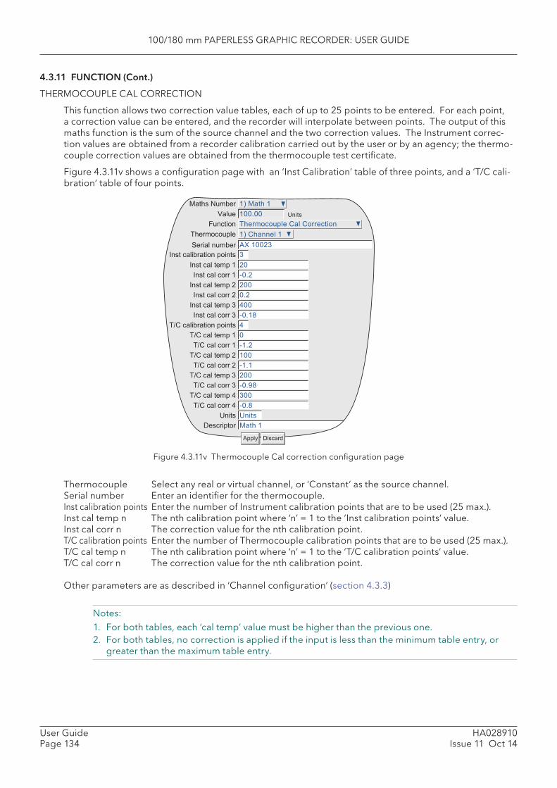
100/180 mm PAPERLESS GRAPHIC RECORDER: USER GUIDE
HA028910Issue 11 Oct 14
User GuidePage 134
4.3.11 FUNCTION (Cont.)
THERMOCOUPLE CAL CORRECTION
This function allows two correction value tables, each of up to 25 points to be entered. For each point, a correction value can be entered, and the recorder will interpolate between points. The output of this maths function is the sum of the source channel and the two correction values. The Instrument correc-tion values are obtained from a recorder calibration carried out by the user or by an agency; the thermo-couple correction values are obtained from the thermocouple test certifi cate.
Figure 4.3.11v shows a confi guration page with an ‘Inst Calibration’ table of three points, and a ‘T/C cali-bration‘ table of four points.
Figure 4.3.11v Thermocouple Cal correction confi guration page
Thermocouple Select any real or virtual channel, or ‘Constant’ as the source channel.Serial number Enter an identifi er for the thermocouple. Inst calibration points Enter the number of Instrument calibration points that are to be used (25 max.). Inst cal temp n The nth calibration point where ‘n’ = 1 to the ‘Inst calibration points’ value. Inst cal corr n The correction value for the nth calibration point.T/C calibration points Enter the number of Thermocouple calibration points that are to be used (25 max.). T/C cal temp n The nth calibration point where ‘n’ = 1 to the ‘T/C calibration points’ value. T/C cal corr n The correction value for the nth calibration point.
Other parameters are as described in ‘Channel confi guration’ (section 4.3.3)
Notes:1. For both tables, each ‘cal temp’ value must be higher than the previous one.2. For both tables, no correction is applied if the input is less than the minimum table entry, or
greater than the maximum table entry.
&���
2������� ��� '�� '��������
)
(?
�% '������ �
"= �??()
�% ,�� �
�??8??
2������� ���
� �����
��� �
,��� � ����
������ � ����
I�� ���������� �����
I�� ��� ��� �
I�� ��� ���� �
I�� ��� ��� (
I�� ��� ���� (
I�� ��� ��� )
I�� ��� ���� )
2�' ���������� �����
2�' ��� ��� �
2�' ��� ���� �
2�' ��� ��� (
2�' ��� ���� (
2�' ��� ��� )
2�' ��� ���� )
2�' ��� ��� �
2�' ��� ���� �
&���
#��������
J?8(
(??
?8(
�??
J?8�9
�
?
J�8(
�??
J�8�
(??
J?8@9
)??
J?89
&���
,�� �
"���� #������
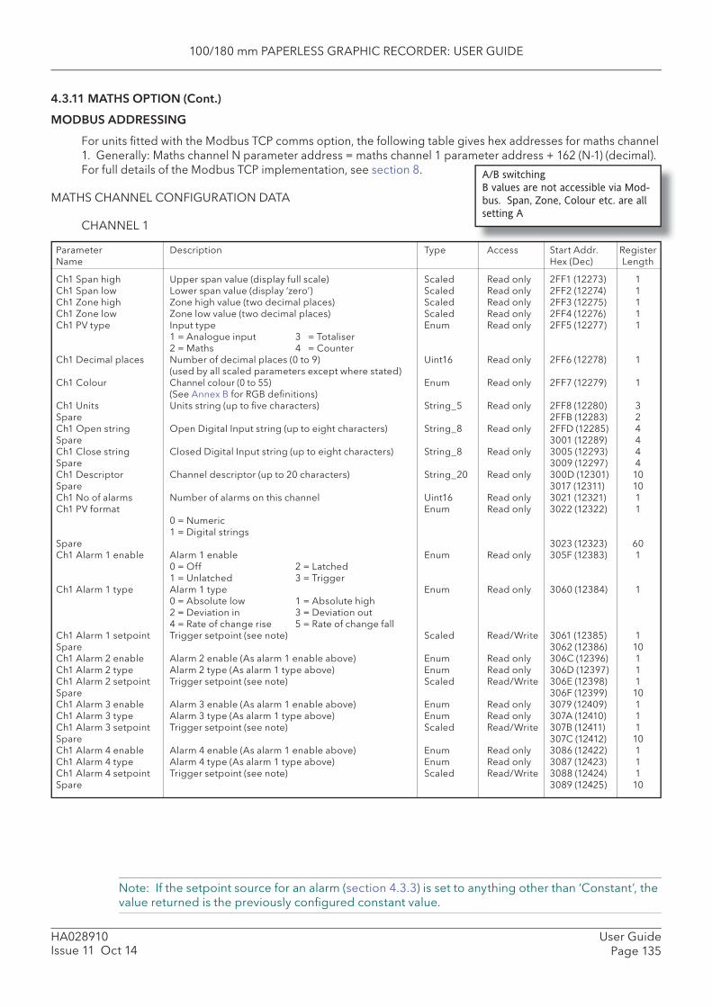
100/180 mm PAPERLESS GRAPHIC RECORDER: USER GUIDE
User GuidePage 135
HA028910Issue 11 Oct 14
4.3.11 MATHS OPTION (Cont.)
MODBUS ADDRESSING
For units fi tted with the Modbus TCP comms option, the following table gives hex addresses for maths channel 1. Generally: Maths channel N parameter address = maths channel 1 parameter address + 162 (N-1) (decimal). For full details of the Modbus TCP implementation, see section 8.
MATHS CHANNEL CONFIGURATION DATA
CHANNEL 1
Ch1 Span high Upper span value (display full scale) Scaled Read only 2FF1 (12273) 1Ch1 Span low Lower span value (display ‘zero’) Scaled Read only 2FF2 (12274) 1Ch1 Zone high Zone high value (two decimal places) Scaled Read only 2FF3 (12275) 1Ch1 Zone low Zone low value (two decimal places) Scaled Read only 2FF4 (12276) 1Ch1 PV type Input type Enum Read only 2FF5 (12277) 1 1 = Analogue input 3 = Totaliser 2 = Maths 4 = CounterCh1 Decimal places Number of decimal places (0 to 9) Uint16 Read only 2FF6 (12278) 1 (used by all scaled parameters except where stated)Ch1 Colour Channel colour (0 to 55) Enum Read only 2FF7 (12279) 1 (See Annex B for RGB defi nitions)Ch1 Units Units string (up to fi ve characters) String_5 Read only 2FF8 (12280) 3Spare 2FFB (12283) 2Ch1 Open string Open Digital Input string (up to eight characters) String_8 Read only 2FFD (12285) 4Spare 3001 (12289) 4Ch1 Close string Closed Digital Input string (up to eight characters) String_8 Read only 3005 (12293) 4Spare 3009 (12297) 4Ch1 Descriptor Channel descriptor (up to 20 characters) String_20 Read only 300D (12301) 10Spare 3017 (12311) 10Ch1 No of alarms Number of alarms on this channel Uint16 Read only 3021 (12321) 1Ch1 PV format Enum Read only 3022 (12322) 1 0 = Numeric 1 = Digital stringsSpare 3023 (12323) 60Ch1 Alarm 1 enable Alarm 1 enable Enum Read only 305F (12383) 1 0 = Off 2 = Latched 1 = Unlatched 3 = Trigger Ch1 Alarm 1 type Alarm 1 type Enum Read only 3060 (12384) 1 0 = Absolute low 1 = Absolute high 2 = Deviation in 3 = Deviation out 4 = Rate of change rise 5 = Rate of change fallCh1 Alarm 1 setpoint Trigger setpoint (see note) Scaled Read/Write 3061 (12385) 1Spare 3062 (12386) 10Ch1 Alarm 2 enable Alarm 2 enable (As alarm 1 enable above) Enum Read only 306C (12396) 1Ch1 Alarm 2 type Alarm 2 type (As alarm 1 type above) Enum Read only 306D (12397) 1Ch1 Alarm 2 setpoint Trigger setpoint (see note) Scaled Read/Write 306E (12398) 1Spare 306F (12399) 10Ch1 Alarm 3 enable Alarm 3 enable (As alarm 1 enable above) Enum Read only 3079 (12409) 1Ch1 Alarm 3 type Alarm 3 type (As alarm 1 type above) Enum Read only 307A (12410) 1Ch1 Alarm 3 setpoint Trigger setpoint (see note) Scaled Read/Write 307B (12411) 1Spare 307C (12412) 10Ch1 Alarm 4 enable Alarm 4 enable (As alarm 1 enable above) Enum Read only 3086 (12422) 1Ch1 Alarm 4 type Alarm 4 type (As alarm 1 type above) Enum Read only 3087 (12423) 1Ch1 Alarm 4 setpoint Trigger setpoint (see note) Scaled Read/Write 3088 (12424) 1Spare 3089 (12425) 10
A/B switching
B values are not accessible via Mod-
bus. Span, Zone, Colour etc. are all
setting A
Parameter Description Type Access Start Addr. RegisterName Hex (Dec) Length
Note: If the setpoint source for an alarm (section 4.3.3) is set to anything other than ‘Constant’, the value returned is the previously confi gured constant value.

100/180 mm PAPERLESS GRAPHIC RECORDER: USER GUIDE
HA028910Issue 11 Oct 14
User GuidePage 136
4.3.11 MATHS OPTION (Cont.)
MATHS CHANNEL RUN-TIME DATA
This table show addresses for maths channel 1 run-time data. Generally: channel N address = channel 1 address + 3(N-1) (decimal)
CHANNEL 1
Ch1 value Current process value (PV) Scaled Read/Write A2BA (41658) 1Ch1 status Channel status Enum Read only A2BB (41659) 1 0 = Good PV 5 = Ranging error 1 = Channel off 6 = Overfl ow 2 = Over range 7 = Bad PV 3 = Under range 8 = No data 4 = Hardware errorCh1 Alarms Alarm information Uint16 - A2BC (41660) 1 Bit 0:0 = Alarm 1 inactive; 1 = Alarm 1 active Read only Bit 1: 0 = No alarm 1 Ack. required; 1 = Ack. required Read only Bit 2: 1 = Acknowledge alarm 1 Read/Write Bit 3: Spare Bit 4: 0 = Alarm 2 inactive; 1 = Alarm 2 active Read only Bit 5: 0 = No Alarm 2 Ack. required; 1 = Ack. required Read only Bit 6: 1 = Acknowledge alarm 2 Read/Write Bit 7: Spare Bit 8: 0 = Alarm 3 inactive; 1 = Alarm 3 active Read only Bit 9: 0 = No alarm 3 Ack. required; 1 = Ack. required Read only Bit 10: 1 = Acknowledge alarm 3 Read/Write Bit 11: Spare Bit 12: 0 = Alarm 4 inactive; 1 = Alarm 4 active Read only Bit 13: 0 = No Alarm 4 Ack. required; 1 = Ack. required Read only Bit 14: 1 = Acknowledge alarm 4 Read/Write Bit 15: Spare
IEEE 32-BIT CHANNEL CONFIGURATION DATA
The following table shows addresses for the specifi ed 32-bit fl oating-point values, for Maths channel 1. Generally, Parameter address for channel N = Parameter address for channel 1 + 36(N-1) (decimal).
CHANNEL 1
Ch1 span high Upper span value (Display full scale) Float Read only DF73 (57203) 2Ch1 span low Lower span value (display ‘zero’) Float Read only DF75 (57205) 2Ch1 Zone high Zone upper value (% of ‘chart’ width) Float Read only DF77 (57207) 2Ch1 Zone low Zone lower value (% of ‘chart’ width) Float Read only DF79 (57209) 2Ch1 Alarm 1 setpoint Trigger setpoint for alarm 1 (see note) Float Read/Write DF7B (57211) 2Ch1 Alarm 2 setpoint Trigger setpoint for alarm 2 (see note) Float Read/Write DF7D (57213) 2Ch 1 Alarm 3 setpoint Trigger setpoint for alarm 3 (see note) Float Read/Write DF7F (57215) 2Ch 1 Alarm 4 setpoint Trigger setpoint for alarm 4 (see note) Float Read/Write DF81 (57217) 2Spare DF83 (57219) 20
Parameter Description Type Access Start Addr. RegisterName Hex (Dec) Length
Parameter Description Type Access Start Addr. RegisterName Hex (Dec) Length
Note: If the setpoint source for an alarm (section 4.3.3) is set to anything other than ‘Constant’, the value returned is the previously confi gured constant value.

100/180 mm PAPERLESS GRAPHIC RECORDER: USER GUIDE
User GuidePage 137
HA028910Issue 11 Oct 14
4.3.11 MATHS OPTION (Cont.)
IEEE 32-BIT CHANNEL RUN-TIME DATA
The following table gives addresses for the specifi ed 32-bit fl oating-point values, for maths channel 1. Generally, Parameter address for channel N = Parameter address for channel 1 + 4(N-1) (decimal).
CHANNEL 1
Channel 1 value Current process value (PV) Float Read/Write F9EF (63983) 2Channel 1 status Channel status Enum Read only F9F1 (63985) 1 0 = Good PV 5 = Ranging error 1 = Channel off 6 = Overfl ow 2 = Over range 7 = Bad PV 3 = Under range 8 = No data 4 = Hardware errorChannel 1 Alarms Alarm information Uint16 - F9F2 (63986) 1 Bit 0: 0 = Alarm 1 inactive; 1 = Alarm 1 active Read only Bit 1: 0 = No alarm 1 Ack. required; 1 = Ack. required Read only Bit 2: 1 = Acknowledge alarm 1 Read/Write Bit 3: Spare Bit 4: 0 = Alarm 2 inactive; 1 = Alarm 2 active Read only Bit 5: 0 = No Alarm 2 Ack. required; 1 = Ack. required Read only Bit 6: 1 = Acknowledge alarm 2 Read/Write Bit 7: Spare Bit 8: 0 = Alarm 3 inactive; 1 = Alarm 3 active Read only Bit 9: 0 = No alarm 3 Ack. required; 1 = Ack. required Read only Bit 10: 1 = Acknowledge alarm 3 Read/Write Bit 11: Spare Bit 12: 0 = Alarm 4 inactive; 1 = Alarm 4 active Read only Bit 13: 0 = No Alarm 4 Ack. required; 1 = Ack. required Read only Bit 14: 1 = Acknowledge alarm 4 Read/Write Bit 15: Spare
Parameter Description Type Access Start Addr. RegisterName Hex (Dec) Length
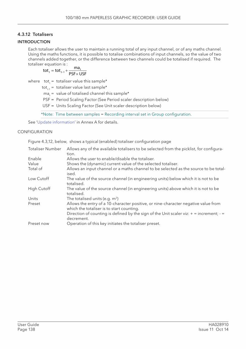
100/180 mm PAPERLESS GRAPHIC RECORDER: USER GUIDE
HA028910Issue 11 Oct 14
User GuidePage 138
4.3.12 Totalisers
INTRODUCTION
Each totaliser allows the user to maintain a running total of any input channel, or of any maths channel. Using the maths functions, it is possible to totalise combinations of input channels, so the value of two channels added together, or the difference between two channels could be totalised if required. The totaliser equation is :
where tott = totaliser value this sample* tott-1 = totaliser value last sample* mat = value of totalised channel this sample* PSF = Period Scaling Factor (See Period scaler description below) USF = Units Scaling Factor (See Unit scaler description below)
*Note: Time between samples = Recording interval set in Group confi guration.
See ‘Update information’ in Annex A for details.
CONFIGURATION
Figure 4.3,12, below, shows a typical (enabled) totaliser confi guration page
Totaliser Number Allows any of the available totalisers to be selected from the picklist, for confi gura-tion.
Enable Allows the user to enable/disable the totaliser. Value Shows the (dynamic) current value of the selected totaliser. Total of Allows an input channel or a maths channel to be selected as the source to be total-
ised. Low Cutoff The value of the source channel (in engineering units) below which it is not to be
totalised. High Cutoff The value of the source channel (in engineering units) above which it is not to be
totalised. Units The totalised units (e.g. m3) Preset Allows the entry of a 10-character positive, or nine-character negative value from
which the totaliser is to start counting. Direction of counting is defi ned by the sign of the Unit scaler viz: + = increment; - =
decrement. Preset now Operation of this key initiates the totaliser preset.
tot t tot t1
mat
PSFUSF
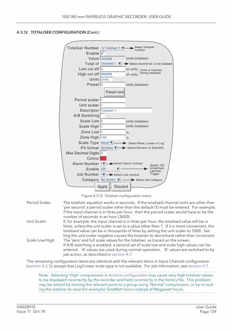
100/180 mm PAPERLESS GRAPHIC RECORDER: USER GUIDE
User GuidePage 139
HA028910Issue 11 Oct 14
4.3.12 TOTALISER CONFIGURATION (Cont.)
Figure 4.3.12 Totaliser confi guration menu
Period Scaler The totaliser equation works in seconds. If the totalised channel units are other than ‘per second’ a period scaler other than the default (1) must be entered. For example, if the input channel is in litres per hour, then the period scaler would have to be the number of seconds in an hour (3600).
Unit Scaler If, for example, the input channel is in litres per hour, the totalised value will be in litres, unless the unit scaler is set to a value other than 1. If it is more convenient, the totalised value can be in thousands of litres by setting the unit scaler to 1000. Set-ting the unit scaler negative causes the totaliser to decrement rather than increment.
Scale Low/High The ‘zero’ and full scale values for the totaliser, as traced on the screen.If A/B switching is enabled, a second set of scale low and scale high values can be entered. ‘A’ values are used during normal operation. ‘B’ values are switched to by job action, as described in section 4.7.
The remaining confi guration items are identical with the relevant items in Input Channel confi guration (section 4.3.3), except that Log/Linear scale type is not available. For job information, see section 4.7.
Note: Selecting ‘High’ compression in Archive confi guration may cause very high totaliser values to be displayed incorrectly by the recorder and held incorrectly in the history fi le. This problem may be solved by moving the relevant point to a group using ‘Normal’ compression, or by re-scal-ing the totaliser to read (for example) TeraWatt hours instead of Megawatt hours.
Apply Discard
Totaliser Number Select totalisernumber
Enable
Select Alarm numberAlarm NumberEnable
Job NumberCategory
Select: Off,Unlatched,Latched,Trigger
Select Job category
ValueTotal of
Low cut offHigh cut off
UnitsPreset
Preset now
123456
Select channel etc. to be totalised
ch units
ch units
Units of channelbeing totalised
Units (totaliser)
Period scalerUnit scalerDescriptor
Units (totaliser)
Scale LowScale High
Units (totaliser)
Units (totaliser)
Zone LowZone High
%
%
Max Decimal DigitsColour
Scale Type Select None, Linear or LogNone
PV format Select Numeric or Scientific
A/B Switching
Select Job number
1) Totaliser 1
1
Off
1
No Action
Channel 1
0
999999
Units
0
1
1
Totaliser 1
0
1
1
100
4
0
Numeric
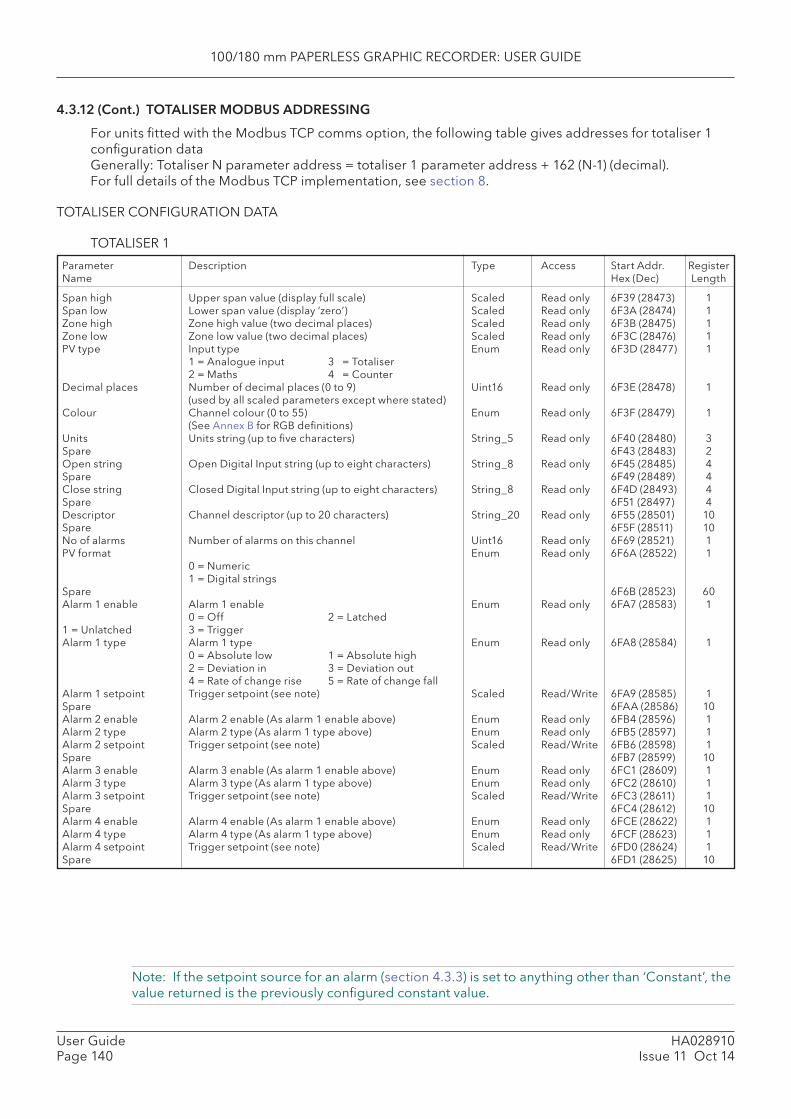
100/180 mm PAPERLESS GRAPHIC RECORDER: USER GUIDE
HA028910Issue 11 Oct 14
User GuidePage 140
4.3.12 (Cont.) TOTALISER MODBUS ADDRESSING
For units fi tted with the Modbus TCP comms option, the following table gives addresses for totaliser 1 confi guration dataGenerally: Totaliser N parameter address = totaliser 1 parameter address + 162 (N-1) (decimal).For full details of the Modbus TCP implementation, see section 8.
TOTALISER CONFIGURATION DATA
TOTALISER 1
Span high Upper span value (display full scale) Scaled Read only 6F39 (28473) 1Span low Lower span value (display ‘zero’) Scaled Read only 6F3A (28474) 1Zone high Zone high value (two decimal places) Scaled Read only 6F3B (28475) 1Zone low Zone low value (two decimal places) Scaled Read only 6F3C (28476) 1PV type Input type Enum Read only 6F3D (28477) 1 1 = Analogue input 3 = Totaliser 2 = Maths 4 = CounterDecimal places Number of decimal places (0 to 9) Uint16 Read only 6F3E (28478) 1 (used by all scaled parameters except where stated)Colour Channel colour (0 to 55) Enum Read only 6F3F (28479) 1 (See Annex B for RGB defi nitions)Units Units string (up to fi ve characters) String_5 Read only 6F40 (28480) 3Spare 6F43 (28483) 2Open string Open Digital Input string (up to eight characters) String_8 Read only 6F45 (28485) 4Spare 6F49 (28489) 4Close string Closed Digital Input string (up to eight characters) String_8 Read only 6F4D (28493) 4Spare 6F51 (28497) 4Descriptor Channel descriptor (up to 20 characters) String_20 Read only 6F55 (28501) 10Spare 6F5F (28511) 10No of alarms Number of alarms on this channel Uint16 Read only 6F69 (28521) 1PV format Enum Read only 6F6A (28522) 1 0 = Numeric 1 = Digital stringsSpare 6F6B (28523) 60Alarm 1 enable Alarm 1 enable Enum Read only 6FA7 (28583) 1 0 = Off 2 = Latched1 = Unlatched 3 = Trigger Alarm 1 type Alarm 1 type Enum Read only 6FA8 (28584) 1 0 = Absolute low 1 = Absolute high 2 = Deviation in 3 = Deviation out 4 = Rate of change rise 5 = Rate of change fall Alarm 1 setpoint Trigger setpoint (see note) Scaled Read/Write 6FA9 (28585) 1Spare 6FAA (28586) 10Alarm 2 enable Alarm 2 enable (As alarm 1 enable above) Enum Read only 6FB4 (28596) 1Alarm 2 type Alarm 2 type (As alarm 1 type above) Enum Read only 6FB5 (28597) 1Alarm 2 setpoint Trigger setpoint (see note) Scaled Read/Write 6FB6 (28598) 1Spare 6FB7 (28599) 10Alarm 3 enable Alarm 3 enable (As alarm 1 enable above) Enum Read only 6FC1 (28609) 1Alarm 3 type Alarm 3 type (As alarm 1 type above) Enum Read only 6FC2 (28610) 1Alarm 3 setpoint Trigger setpoint (see note) Scaled Read/Write 6FC3 (28611) 1Spare 6FC4 (28612) 10Alarm 4 enable Alarm 4 enable (As alarm 1 enable above) Enum Read only 6FCE (28622) 1Alarm 4 type Alarm 4 type (As alarm 1 type above) Enum Read only 6FCF (28623) 1Alarm 4 setpoint Trigger setpoint (see note) Scaled Read/Write 6FD0 (28624) 1Spare 6FD1 (28625) 10
Parameter Description Type Access Start Addr. RegisterName Hex (Dec) Length
Note: If the setpoint source for an alarm (section 4.3.3) is set to anything other than ‘Constant’, the value returned is the previously confi gured constant value.
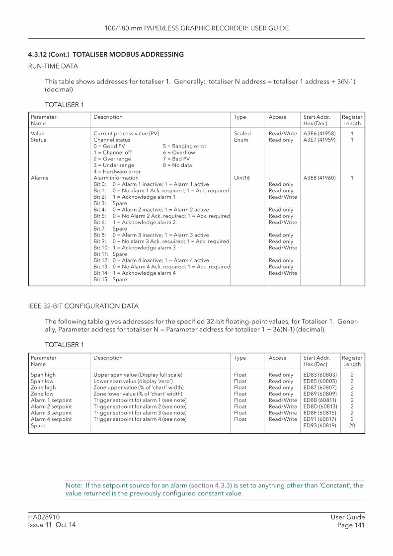
100/180 mm PAPERLESS GRAPHIC RECORDER: USER GUIDE
User GuidePage 141
HA028910Issue 11 Oct 14
4.3.12 (Cont.) TOTALISER MODBUS ADDRESSING
RUN-TIME DATA
This table shows addresses for totaliser 1. Generally: totaliser N address = totaliser 1 address + 3(N-1) (decimal)
TOTALISER 1
Parameter Description Type Access Start Addr. RegisterName Hex (Dec) Length
Value Current process value (PV) Scaled Read/Write A3E6 (41958) 1Status Channel status Enum Read only A3E7 (41959) 1 0 = Good PV 5 = Ranging error 1 = Channel off 6 = Overfl ow 2 = Over range 7 = Bad PV 3 = Under range 8 = No data 4 = Hardware errorAlarms Alarm information Uint16 - A3E8 (41960) 1 Bit 0: 0 = Alarm 1 inactive; 1 = Alarm 1 active Read only Bit 1: 0 = No alarm 1 Ack. required; 1 = Ack. required Read only Bit 2: 1 = Acknowledge alarm 1 Read/Write Bit 3: Spare Bit 4: 0 = Alarm 2 inactive; 1 = Alarm 2 active Read only Bit 5: 0 = No Alarm 2 Ack. required; 1 = Ack. required Read only Bit 6: 1 = Acknowledge alarm 2 Read/Write Bit 7: Spare Bit 8: 0 = Alarm 3 inactive; 1 = Alarm 3 active Read only Bit 9: 0 = No alarm 3 Ack. required; 1 = Ack. required Read only Bit 10: 1 = Acknowledge alarm 3 Read/Write Bit 11: Spare Bit 12: 0 = Alarm 4 inactive; 1 = Alarm 4 active Read only Bit 13: 0 = No Alarm 4 Ack. required; 1 = Ack. required Read only Bit 14: 1 = Acknowledge alarm 4 Read/Write Bit 15: Spare
IEEE 32-BIT CONFIGURATION DATA
The following table gives addresses for the specifi ed 32-bit fl oating-point values, for Totaliser 1. Gener-ally, Parameter address for totaliser N = Parameter address for totaliser 1 + 36(N-1) (decimal).
TOTALISER 1
Parameter Description Type Access Start Addr. RegisterName Hex (Dec) Length
Span high Upper span value (Display full scale) Float Read only ED83 (60803) 2Span low Lower span value (display ‘zero’) Float Read only ED85 (60805) 2Zone high Zone upper value (% of ‘chart’ width) Float Read only ED87 (60807) 2Zone low Zone lower value (% of ‘chart’ width) Float Read only ED89 (60809) 2Alarm 1 setpoint Trigger setpoint for alarm 1 (see note) Float Read/Write ED8B (60811) 2Alarm 2 setpoint Trigger setpoint for alarm 2 (see note) Float Read/Write ED8D (60813) 2Alarm 3 setpoint Trigger setpoint for alarm 3 (see note) Float Read/Write ED8F (60815) 2Alarm 4 setpoint Trigger setpoint for alarm 4 (see note) Float Read/Write ED91 (60817) 2Spare ED93 (60819) 20
Note: If the setpoint source for an alarm (section 4.3.3) is set to anything other than ‘Constant’, the value returned is the previously confi gured constant value.
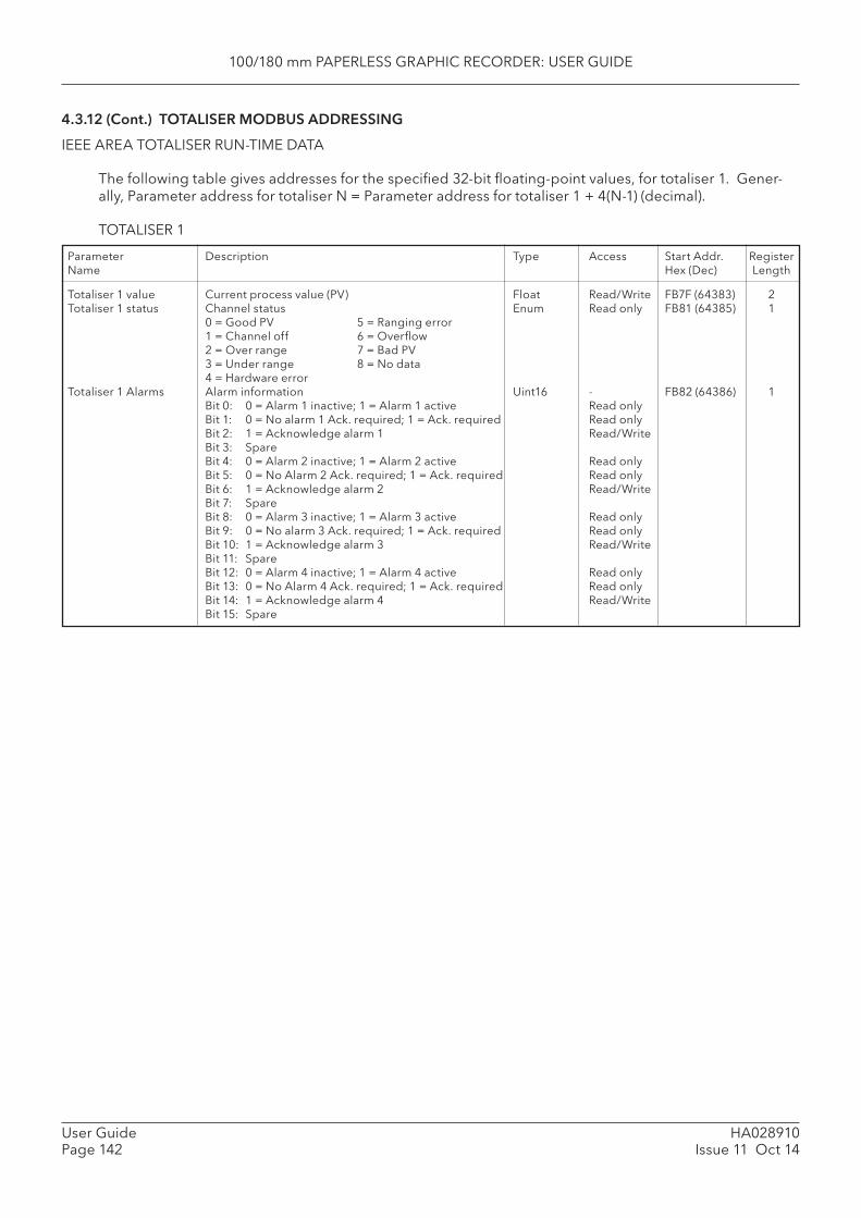
100/180 mm PAPERLESS GRAPHIC RECORDER: USER GUIDE
HA028910Issue 11 Oct 14
User GuidePage 142
4.3.12 (Cont.) TOTALISER MODBUS ADDRESSING
IEEE AREA TOTALISER RUN-TIME DATA
The following table gives addresses for the specifi ed 32-bit fl oating-point values, for totaliser 1. Gener-ally, Parameter address for totaliser N = Parameter address for totaliser 1 + 4(N-1) (decimal).
TOTALISER 1
Parameter Description Type Access Start Addr. RegisterName Hex (Dec) Length
Totaliser 1 value Current process value (PV) Float Read/Write FB7F (64383) 2Totaliser 1 status Channel status Enum Read only FB81 (64385) 1 0 = Good PV 5 = Ranging error 1 = Channel off 6 = Overfl ow 2 = Over range 7 = Bad PV 3 = Under range 8 = No data 4 = Hardware errorTotaliser 1 Alarms Alarm information Uint16 - FB82 (64386) 1 Bit 0: 0 = Alarm 1 inactive; 1 = Alarm 1 active Read only Bit 1: 0 = No alarm 1 Ack. required; 1 = Ack. required Read only Bit 2: 1 = Acknowledge alarm 1 Read/Write Bit 3: Spare Bit 4: 0 = Alarm 2 inactive; 1 = Alarm 2 active Read only Bit 5: 0 = No Alarm 2 Ack. required; 1 = Ack. required Read only Bit 6: 1 = Acknowledge alarm 2 Read/Write Bit 7: Spare Bit 8: 0 = Alarm 3 inactive; 1 = Alarm 3 active Read only Bit 9: 0 = No alarm 3 Ack. required; 1 = Ack. required Read only Bit 10: 1 = Acknowledge alarm 3 Read/Write Bit 11: Spare Bit 12: 0 = Alarm 4 inactive; 1 = Alarm 4 active Read only Bit 13: 0 = No Alarm 4 Ack. required; 1 = Ack. required Read only Bit 14: 1 = Acknowledge alarm 4 Read/Write Bit 15: Spare
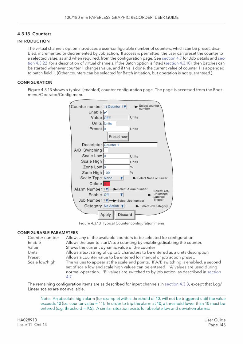
100/180 mm PAPERLESS GRAPHIC RECORDER: USER GUIDE
User GuidePage 143
HA028910Issue 11 Oct 14
4.3.13 Counters
INTRODUCTION
The virtual channels option introduces a user-confi gurable number of counters, which can be preset, disa-bled, incremented or decremented by Job action. If access is permitted, the user can preset the counter to a selected value, as and when required, from the confi guration page. See section 4.7 for Job details and sec-tion 4.3.22 for a description of virtual channels. If the Batch option is fi tted (section 4.3.10), then batches can be started whenever counter 1 changes value, and if this is done, the current value of counter 1 is appended to batch fi eld 1. (Other counters can be selected for Batch initiation, but operation is not guaranteed.)
CONFIGURATION
Figure 4.3.13 shows a typical (enabled) counter confi guration page. The page is accessed from the Root menu/Operator/Confi g menu.
Apply Discard
Counter number Select counternumber
Enable
Select Alarm numberAlarm NumberEnable
Job NumberCategory
Select: Off,Unlatched,Latched,Trigger
Select Job category
Value
UnitsPreset
Preset now
Units
Descriptor
Units
Scale LowScale High
Units
Units
Zone LowZone High
%
%
Colour
Scale Type Select None or LinearNone
A/B Switching
Select Job number
1) Counter 1
1
Off
1
No Action
OFF
Units
0
Counter 1
0
1
0
100
0
Figure 4.3.13 Typical Counter confi guration menu
CONFIGURABLE PARAMETERS Counter number Allows any of the available counters to be selected for confi guration Enable Allows the user to start/stop counting by enabling/disabling the counter. Value Shows the current dynamic value of the counter Units Allows a text string of up to 5 characters to be entered as a units description Preset Allows a counter value to be entered for manual or job action preset. Scale low/high The values to appear at the scale end points. If A/B switching is enabled, a second
set of scale low and scale high values can be entered. ‘A’ values are used during normal operation. ‘B’ values are switched to by job action, as described in section 4.7.
The remaining confi guration items are as described for input channels in section 4.3.3, except that Log/Linear scales are not available.
Note: An absolute high alarm (for example) with a threshold of 10, will not be triggered until the value exceeds 10 (i.e. counter value = 11). In order to trip the alarm at 10, a threshold lower than 10 must be entered (e.g. threshold = 9.5). A similar situation exists for absolute low and deviation alarms.
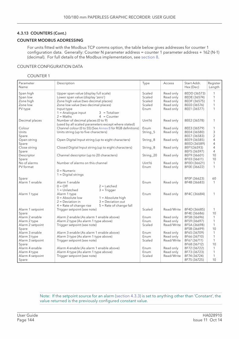
100/180 mm PAPERLESS GRAPHIC RECORDER: USER GUIDE
HA028910Issue 11 Oct 14
User GuidePage 144
4.3.13 COUNTERS (Cont.)
COUNTER MODBUS ADDRESSING
For units fi tted with the Modbus TCP comms option, the table below gives addresses for counter 1 confi guration data. Generally: Counter N parameter address = counter 1 parameter address + 162 (N-1) (decimal). For full details of the Modbus implementation, see section 8.
COUNTER CONFIGURATION DATA
COUNTER 1
Note: If the setpoint source for an alarm (section 4.3.3) is set to anything other than ‘Constant’, the value returned is the previously confi gured constant value.
Parameter Description Type Access Start Addr. RegisterName Hex (Dec) Length
Span high Upper span value (display full scale) Scaled Read only 8EDD (36573) 1Span low Lower span value (display ‘zero’) Scaled Read only 8EDE (36574) 1Zone high Zone high value (two decimal places) Scaled Read only 8EDF (36575) 1Zone low Zone low value (two decimal places) Scaled Read only 8EE0 (36576) 1PV type Input type Enum Read only 8EE1 (36577) 1 1 = Analogue input 3 = Totaliser 2 = Maths 4 = CounterDecimal places Number of decimal places (0 to 9) Uint16 Read only 8EE2 (36578) 1 (used by all scaled parameters except where stated)Colour Channel colour (0 to 55) (See Annex B for RGB defi nitions) Enum Read only 8EE3 (36579) 1Units Units string (up to fi ve characters) String_5 Read only 8EE4 (36580) 3Spare 8EE7 (36583) 2Open string Open Digital Input string (up to eight characters) String_8 Read only 8EE9 (36585) 4Spare 8EED (36589) 4Close string Closed Digital Input string (up to eight characters) String_8 Read only 8EF1(36593) 4Spare 8EF5 (36597) 4Descriptor Channel descriptor (up to 20 characters) String_20 Read only 8EF9 (36601) 10Spare 8F03 (36611) 10No of alarms Number of alarms on this channel Uint16 Read only 8F0D (36621) 1PV format Enum Read only 8F0E (36622) 1 0 = Numeric 1 = Digital stringsSpare 8F0F (36623) 60Alarm 1 enable Alarm 1 enable Enum Read only 8F4B (36683) 1 0 = Off 2 = Latched 1 = Unlatched 3 = Trigger Alarm 1 type Alarm 1 type Enum Read only 8F4C (36684) 1 0 = Absolute low 1 = Absolute high 2 = Deviation in 3 = Deviation out 4 = Rate of change rise 5 = Rate of change fall Alarm 1 setpoint Trigger setpoint (see note) Scaled Read/Write 8F4D (36685) 1Spare 8F4E (36686) 10Alarm 2 enable Alarm 2 enable (As alarm 1 enable above) Enum Read only 8F58 (36696) 1Alarm 2 type Alarm 2 type (As alarm 1 type above) Enum Read only 8F59 (36697) 1Alarm 2 setpoint Trigger setpoint (see note) Scaled Read/Write 8F5A (36698) 1Spare 8F5B (36699) 10Alarm 3 enable Alarm 3 enable (As alarm 1 enable above) Enum Read only 8F65 (36709) 1Alarm 3 type Alarm 3 type (As alarm 1 type above) Enum Read only 8F66 (36710) 1Alarm 3 setpoint Trigger setpoint (see note) Scaled Read/Write 8F67 (36711) 1Spare 8F68 (36712) 10Alarm 4 enable Alarm 4 enable (As alarm 1 enable above) Enum Read only 8F72 (36722) 1Alarm 4 type Alarm 4 type (As alarm 1 type above) Enum Read only 8F73 (36723) 1Alarm 4 setpoint Trigger setpoint (see note) Scaled Read/Write 8F74 (36724) 1Spare 8F75 (36725) 10

100/180 mm PAPERLESS GRAPHIC RECORDER: USER GUIDE
User GuidePage 145
HA028910Issue 11 Oct 14
4.3.13 COUNTERS (Cont.)
RUN-TIME DATA
This table shows addresses for counter 1. Generally: Counter N address = counter 1 address + 3(N-1) (decimal)
COUNTER 1
Parameter Description Type Access Start Addr. RegisterName Hex (Dec) Length
Value Current process value (PV) Scaled Read/Write A47C (42108) 1Status Channel status Enum Read only A47D (42109) 1 0 = Good PV 5 = Ranging error 1 = Channel off 6 = Overfl ow 2 = Over range 7 = Bad PV 3 = Under range 8 = No data 4 = Hardware errorAlarms Alarm information Uint16 - A47E (42110) 1 Bit 0: 0 = Alarm 1 inactive; 1 = Alarm 1 active Read only Bit 1: 0 = No alarm 1 Ack. required; 1 = Ack. required Read only Bit 2: 1 = Acknowledge alarm 1 Read/Write Bit 3: Spare Bit 4: 0 = Alarm 2 inactive; 1 = Alarm 2 active Read only Bit 5: 0 = No Alarm 2 Ack. required; 1 = Ack. required Read only Bit 6: 1 = Acknowledge alarm 2 Read/Write Bit 7: Spare Bit 8: 0 = Alarm 3 inactive; 1 = Alarm 3 active Read only Bit 9: 0 = No alarm 3 Ack. required; 1 = Ack. required Read only Bit 10: 1 = Acknowledge alarm 3 Read/Write Bit 11: Spare Bit 12: 0 = Alarm 4 inactive; 1 = Alarm 4 active Read only Bit 13: 0 = No Alarm 4 Ack. required; 1 = Ack. required Read only Bit 14: 1 = Acknowledge alarm 4 Read/Write Bit 15: Spare
IEEE 32-BIT CONFIGURATION DATA
The following table gives addresses for the specifi ed 32-bit fl oating-point values, for Counter 1. Gener-ally, Parameter address for counter N = Parameter address for counter 1 + 36(N-1) (decimal).
COUNTER 1
Parameter Description Type Access Start Addr. RegisterName Hex (Dec) Length
Span high Upper span value (Display full scale) Float Read only F48B (62603) 2Span low Lower span value (display ‘zero’) Float Read only F48D (62605) 2Zone high Zone upper value (% of ‘chart’ width) Float Read only F48F (62607) 2Zone low Zone lower value (% of ‘chart’ width) Float Read only F491 (62609) 2Alarm 1 setpoint Trigger setpoint for alarm 1 (see note) Float Read/Write F493 (62611) 2Alarm 2 setpoint Trigger setpoint for alarm 2 (see note) Float Read/Write F495 (62613) 2Alarm 3 setpoint Trigger setpoint for alarm 3 (see note) Float Read/Write F497 (62615) 2Alarm 4 setpoint Trigger setpoint for alarm 4 (see note) Float Read/Write F499 (62617) 2Spare F49B (62619) 20
Note: If the setpoint source for an alarm (section 4.3.3) is set to anything other than ‘Constant’, the value returned is the previously confi gured constant value.

100/180 mm PAPERLESS GRAPHIC RECORDER: USER GUIDE
HA028910Issue 11 Oct 14
User GuidePage 146
4.3.13 COUNTERS (Cont.)
IEEE AREA COUNTER RUN-TIME DATA
The following table gives addresses for the specifi ed 32-bit fl oating-point values, for counter 1. Gener-ally, Parameter address for counter N = Parameter address for counter 1 + 4(N-1) (decimal).
COUNTER 1
Parameter Description Type Access Start Addr. RegisterName Hex (Dec) Length
Counter 1 value Current process value (PV) Float Read/Write FC47 (64583) 2Counter 1 status Channel status Enum Read only FC49 (64585) 1 0 = Good PV 5 = Ranging error 1 = Channel off 6 = Overfl ow 2 = Over range 7 = Bad PV 3 = Under range 8 = No data 4 = Hardware errorCounter 1 Alarms Alarm information Uint16 - FC4A (64586) 1 Bit 0: 0 = Alarm 1 inactive; 1 = Alarm 1 active Read only Bit 1: 0 = No alarm 1 Ack. required; 1 = Ack. required Read only Bit 2: 1 = Acknowledge alarm 1 Read/Write Bit 3: Spare Bit 4: 0 = Alarm 2 inactive; 1 = Alarm 2 active Read only Bit 5: 0 = No Alarm 2 Ack. required; 1 = Ack. required Read only Bit 6: 1 = Acknowledge alarm 2 Read/Write Bit 7: Spare Bit 8: 0 = Alarm 3 inactive; 1 = Alarm 3 active Read only Bit 9: 0 = No alarm 3 Ack. required; 1 = Ack. required Read only Bit 10: 1 = Acknowledge alarm 3 Read/Write Bit 11: Spare Bit 12: 0 = Alarm 4 inactive; 1 = Alarm 4 active Read only Bit 13: 0 = No Alarm 4 Ack. required; 1 = Ack. required Read only Bit 14: 1 = Acknowledge alarm 4 Read/Write Bit 15: Spare
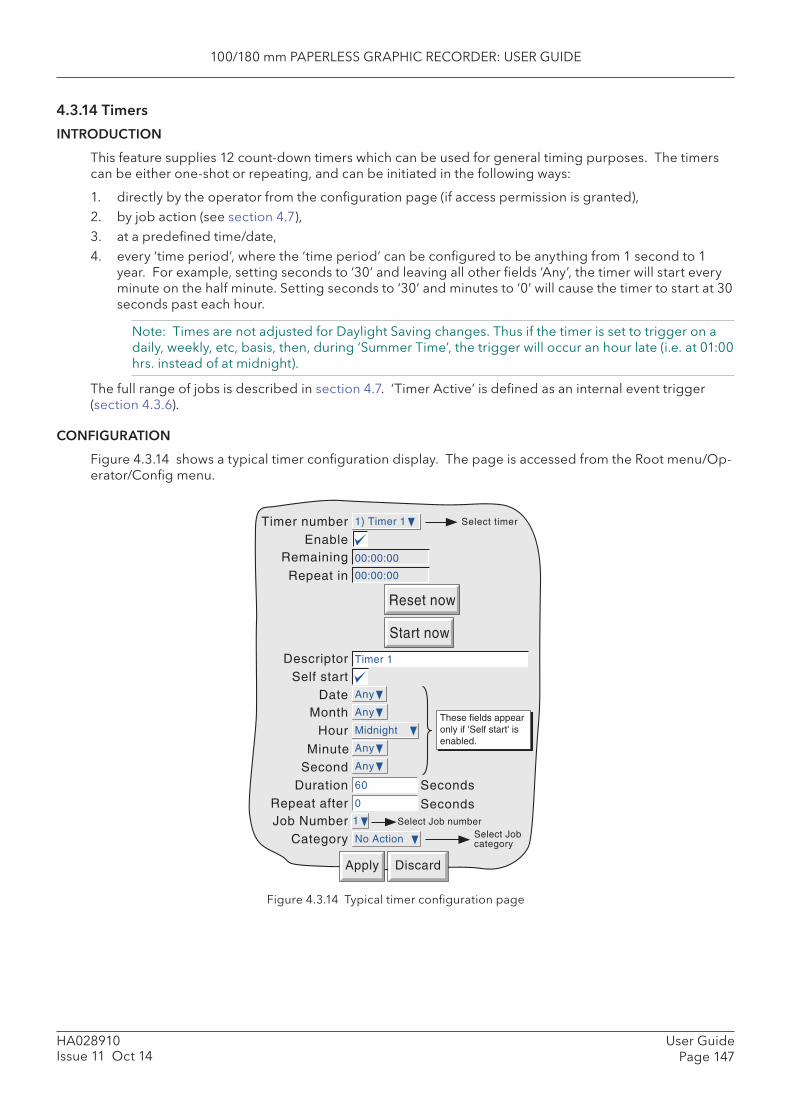
100/180 mm PAPERLESS GRAPHIC RECORDER: USER GUIDE
User GuidePage 147
HA028910Issue 11 Oct 14
4.3.14 Timers
INTRODUCTION
This feature supplies 12 count-down timers which can be used for general timing purposes. The timers can be either one-shot or repeating, and can be initiated in the following ways:
1. directly by the operator from the confi guration page (if access permission is granted), 2. by job action (see section 4.7),3. at a predefi ned time/date,4. every ‘time period’, where the ‘time period’ can be confi gured to be anything from 1 second to 1
year. For example, setting seconds to ‘30’ and leaving all other fi elds ‘Any’, the timer will start every minute on the half minute. Setting seconds to ‘30’ and minutes to ‘0’ will cause the timer to start at 30 seconds past each hour.
Note: Times are not adjusted for Daylight Saving changes. Thus if the timer is set to trigger on a daily, weekly, etc, basis, then, during ‘Summer Time’, the trigger will occur an hour late (i.e. at 01:00 hrs. instead of at midnight).
The full range of jobs is described in section 4.7. ‘Timer Active’ is defi ned as an internal event trigger (section 4.3.6).
CONFIGURATION
Figure 4.3.14 shows a typical timer confi guration display. The page is accessed from the Root menu/Op-erator/Confi g menu.
Figure 4.3.14 Typical timer confi guration page
Timer number Select timer
EnableRemaining
Start now
DescriptorSelf start
DateMonth
Repeat in
Reset now
Apply Discard
SecondDuration
Job Number
Minute
Repeat after
Category
Select Job numberSelect Jobcategory
Hour
Seconds
Seconds
These fields appearonly if 'Self start' isenabled.
1) Timer 1
00:00:00
Timer 1
00:00:00
Any
Any
1
No Action
Midnight
Any
Any
60
0
100/180 mm PAPERLESS GRAPHIC RECORDER: USER GUIDE
HA028910Issue 11 Oct 14
User GuidePage 148
4.3.14 TIMERS (Cont.)
CONFIGURABLE PARAMETERS
Timer number Allows a specifi c timer to be selected for confi guration Enable Allows the user to enable/disable the selected timer Remaining This is a dynamic display showing the time remaining in hours:minutes:seconds for-
mat.Repeat in For repeat timers, shows the time remaining before the repeat is initiated. Display is
00:00:00 whilst timer is counting down. Reset now Allows a running timer to be reset to 00:00:00. Start now Allows the operator to initiate the timer. Descriptor Allows a descriptor to be entered for the timer. Self Start If enabled, this causes date and time selection fi elds to appear as shown in fi gure
4.3.14 above.Date: allows a day number to be selected from a picklist of 1 to N and ‘Any’,
where N is the maximum number of days in the selected month.Month: allows a month number to be entered from a picklist of 1 to 12 and ‘Any’.Hour: allows an hour number to be selected from a picklist of 1 to 23, ‘Midnight’
and ‘Any’.Minute: allows a minutes number to be entered from a picklist of 0 to 59 and ‘Any’.Seconds: allows a seconds value to be entered from a picklist of 0 to 59 and ‘Any’.
Duration Allows the user to enter a count-down time period in seconds. Repeat after Allows the user to enter a repeat rate. It should be noted that the repeat value
includes the duration time. For example, to time down from 50 seconds, every minute, a ‘Duration’ value of 50 seconds should be entered, with a ‘Repeat after’ value of 60 seconds (not 10 seconds).
Note: If Month = ‘Any’, and Day = 31, then the timer will not be triggered in February, April, June, September or November. Similarly, if Day = 30, the timer will not be triggered in February, and so on.
Job confi guration is as described in section 4.7.
SELF-START EXAMPLE
To preset Totaliser number 1 to zero, daily, at midnight:
In totaliser confi guration, enter 0 as the Preset value for Totaliser 1.
In timer confi guration, select:
1. Timer number Timer 12. Enable enabled3 Self start enabled4 Date Any5. Month Any6. Hour Midnight7. Minute 08. Second 09. Duration 0.12510. Repeat after 011. Job number 112. Job category Totaliser13. Action Preset14. Totaliser Totaliser 115. On Active
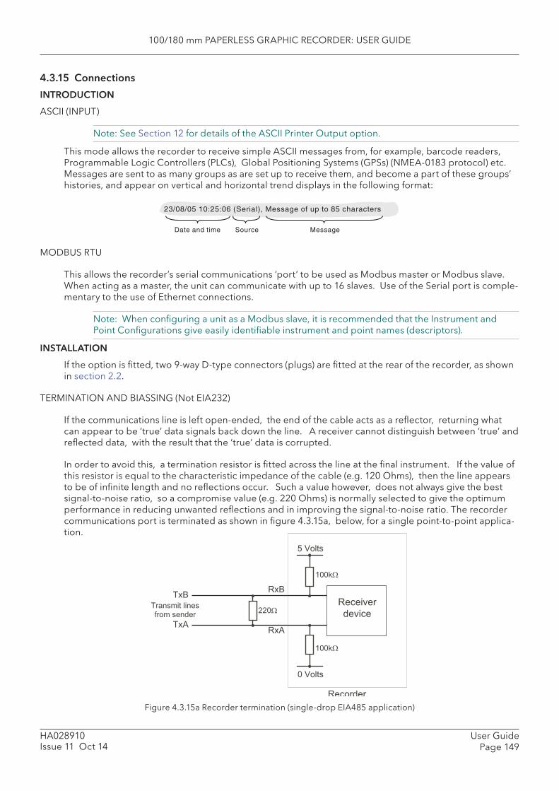
100/180 mm PAPERLESS GRAPHIC RECORDER: USER GUIDE
User GuidePage 149
HA028910Issue 11 Oct 14
4.3.15 Connections
INTRODUCTION
ASCII (INPUT)
Note: See Section 12 for details of the ASCII Printer Output option.
This mode allows the recorder to receive simple ASCII messages from, for example, barcode readers, Programmable Logic Controllers (PLCs), Global Positioning Systems (GPSs) (NMEA-0183 protocol) etc. Messages are sent to as many groups as are set up to receive them, and become a part of these groups’ histories, and appear on vertical and horizontal trend displays in the following format:
Date and time MessageSource
23/08/05 10:25:06 (Serial), Message of up to 85 characters
MODBUS RTU
This allows the recorder’s serial communications ‘port’ to be used as Modbus master or Modbus slave. When acting as a master, the unit can communicate with up to 16 slaves. Use of the Serial port is comple-mentary to the use of Ethernet connections.
Note: When confi guring a unit as a Modbus slave, it is recommended that the Instrument and Point Confi gurations give easily identifi able instrument and point names (descriptors).
INSTALLATION
If the option is fi tted, two 9-way D-type connectors (plugs) are fi tted at the rear of the recorder, as shown in section 2.2.
TERMINATION AND BIASSING (Not EIA232)
If the communications line is left open-ended, the end of the cable acts as a refl ector, returning what can appear to be ‘true’ data signals back down the line. A receiver cannot distinguish between ‘true’ and refl ected data, with the result that the ‘true’ data is corrupted.
In order to avoid this, a termination resistor is fi tted across the line at the fi nal instrument. If the value of this resistor is equal to the characteristic impedance of the cable (e.g. 120 Ohms), then the line appears to be of infi nite length and no refl ections occur. Such a value however, does not always give the best signal-to-noise ratio, so a compromise value (e.g. 220 Ohms) is normally selected to give the optimum performance in reducing unwanted refl ections and in improving the signal-to-noise ratio. The recorder communications port is terminated as shown in fi gure 4.3.15a, below, for a single point-to-point applica-tion.
Figure 4.3.15a Recorder termination (single-drop EIA485 application)
RxB
Recorder
Transmit linesfrom sender
TxB
TxARxA
0 Volts
5 Volts
100kΩ
100kΩ
Receiverdevice220Ω
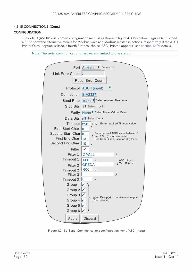
100/180 mm PAPERLESS GRAPHIC RECORDER: USER GUIDE
HA028910Issue 11 Oct 14
User GuidePage 150
4.3.15 CONNECTIONS (Cont.)
CONFIGURATION
The default (ASCII) Serial comms confi guration menu is as shown in fi gure 4.3.15b below. Figures 4.3.15c and 4.3.15d show the alternative menus for Modbus slave and Modbus master selections, respectively. If the ASCII Printer Output option is fi tted, a fourth Protocol choice (ASCII Printer) appears - see section 12 for details.
Note: The serial communications hardware is limited to one start bit.
Figure 4.3.15b Serial Communications confi guration menu (ASCII input)
Apply Discard
250
Baud Rate
Stop Bits
Parity
Data Bits
TimeoutFirst Start Char
Second Start CharFirst End Char
Second End Char
Group 1
Group 2
Group 3
Group 4
Group 5
Group 6
19200
1
None
8ms
0
13
Select required Baud rate.
Select 1 or 2
Select None, Odd or Even
Select 7 or 8
Enter required Timeout value
Enter decimal ASCII value between 0 and 127. (0 = no character.) See User Guide, (section B6) for list.
Select Group(s) to receive messages ( = Receive)
Link Error Count 0
0
10
Reset Error Count
Protocol ASCII (input)
Port Serial 1 Select port
Connection EIA232
Filter
Timeout 1Filter 1
Timeout 2Filter 2
Timeout 3Filter 3
GPGLL
GPZDA600
600
0
s
s
s
ASCII Input Text Filters.

100/180 mm PAPERLESS GRAPHIC RECORDER: USER GUIDE
User GuidePage 151
HA028910Issue 11 Oct 14
4.3.15 CONNECTIONS (Cont.)
Apply Discard
Baud Rate
Stop Bits
Parity
19200
1
Select required Baud rate.
Select 1 or 2
Select None, Odd or EvenNone
Modbus SlaveProtocol
Link Error Count 0
Reset Error Count
Connection EIA232
Port Serial 1 Select port
Apply Discard
Baud Rate
Stop Bits
Parity
Select required Baud rate.
Select 1 or 2
Select None, Odd or Even
Timeout msEnable error code B
Enable Talk Through
Protocol
Link Error Count
Reset Error Count
Connection
Port Select port
19200
1
None
1000
Modbus Master
0
EIA232
Serial 1
CONFIGURATION PARAMETERS SERIAL PORT
Allows the user to select the port to be used for serial communications.
LINK ERROR COUNT
A Link error count is provided for every slave. The count is incremented every time there is a framing error, a parity error or a Cyclic redundancy check (CRC) error. The ‘Reset Error Count’ key is used to reset the count to zero.
PROTOCOL
For the Serial communications board option, ASCII (input), Modbus Slave, Modbus Master or ASCII Printer protocols are available.
CONNECTION
Allows EIA232 or EIA485 to be selected as transmission standard.
BAUD RATE
Allows a Baud rate to be chosen from a picklist of: 300, 600, 1200, 4800, 9600, 19200, 38400. This value must be the same for all devices in the serial link.
STOP BITS
Selectable as 1 or 2. This value must be the same for all devices in the serial link.
PARITY
Allows Parity to be chosen from a pick list of: None, Odd, Even. This value must be the same for all de-vices in the serial link.
DATA BITS
For ASCII (input) protocol only, selectable as 7 or 8. This value must be the same for all devices in the se-rial link.
Figure 4.3.15c Serial Communications confi guration menu (Modbus slave)
Figure 4.3.15d Serial Communications confi guration menu (Modbus master)
100/180 mm PAPERLESS GRAPHIC RECORDER: USER GUIDE
HA028910Issue 11 Oct 14
User GuidePage 152
4.3.15 CONFIGURATION PARAMETERS (Cont.) TIMEOUT
For ASCII (input) protocol, this allows a timeout value to be entered of between 50 and 3000 msec inclu-sive. A value of 0 = no timeout. See also ‘Messaging Information’ below.
For Modbus Master protocol, this allows a timeout to be entered of between 100 and 9,999 msec (inclu-sive), An error code B is generated (if so confi gured - see ‘Enable Error Code B’ below). If the master has not received a reply to a request within the timeout period. For slaves confi gured with their own timeout periods, these will override the entry here.
MESSAGE START/END CHARACTERS
For ASCII (input) protocol only, the message can be prefi xed by 0, 1 or 2 specifi c characters and can be suffi xed by 0, 1 or 2 specifi c characters. The First and Second Start and End characters are entered as decimal ASCII codes between 0 and 127 as required. 0 = no character, 10 = Line Feed; 13 = Carriage Return. See Annex B for a list of ASCII codes. If only one start or end character is required, the fi rst char-acter must be entered, and the second character be entered as zero.
FILTERS
For information on ASCII input text fi lters, refer to section 12.3.3.
GROUP SELECTION
For ASCII input protocol, this allows groups to be deselected/selected for receipt of the messages. A checked box indicates that the associated group will receive the messages.
ENABLE ERROR CODE B
For Modbus Master only.
If enabled, this causes an error code B to be generated in the event of a timeout or a Cyclic Redundancy Check (CRC) error.
ENABLE TALK THROUGH
For Modbus Master only.
If disabled, this prevents ‘external’ (Ethernet) masters from accessing the slaves connected to this instru-ment. (I.E. only this instrument can act as a master to its slaves.)
MESSAGING INFORMATION
Characters are read into a buffer, until the end of message characters are received, or until the time-since-last-character exceeds the entered Timeout value. Date, Time and ‘(Serial)’ are then prefi xed to the message, which is then sent to the selected groups. The date and time relate to when the fi rst buffered character was received. If Start-of-message characters are confi gured, characters will be read into the buffer only after these characters have been received.
The buffer holds up to 120 characters plus date/time etc. and start/end-of-message characters . Further characters are discarded until End-of-message is received, or timeout occurs.
Message characters below Hex 20 (decimal 32) will be replaced by question marks (?).
Message characters above Hex 7F (decimal 127) will be treated as Unicode.

100/180 mm PAPERLESS GRAPHIC RECORDER: USER GUIDE
User GuidePage 153
HA028910Issue 11 Oct 14
4.3.15 CONFIGURATION PARAMETERS (Cont.)
MESSAGING RULES
1 If no start-of-message characters are confi gured, but a timeout value other than 0 has been entered, the new message starts after the timeout period has elapsed.
2 If no end-of-message characters are confi gured, but a timeout value other than 0 has been entered, the new message ends after the timeout period has elapsed.
3 If start-of-message characters are confi gured, and a timeout value other than 0 has been entered, all characters prior to the Start-of-message characters are ignored.
4 If start-of-message characters are confi gured but neither end characters nor timeout have been con-fi gured, then this is an invalid confi guration.
Should this confi guration be a requirement, if the same characters are entered as end-of-message characters instead, then each message will be sent to the groups when the next message is received.
5 If no start or end-of-message characters are entered and no timeout value is entered, all received characters are discarded
6 If a received message is deemed to be corrupt, it is discarded and the software will await a further message.
7 Start and End-of-message characters are removed before the messages are sent to the groups.
MODBUS ADDRESS
When acting as a slave, the recorder will respond both to the address set in Instrument Confi guration (section 4.3.1) and to address 255 (used by some network scanning software).
100/180 mm PAPERLESS GRAPHIC RECORDER: USER GUIDE
User GuidePage 154
HA028910Issue 11 Oct 14
4.3.16 Master comms
INTRODUCTION
This option allows the unit to be used as a Modbus Master unit, as well as a Modbus Slave. The instru-ment can communicate using the Ethernet (RJ45) connection, or by means of one of the serial communi-cations ports (if fi tted - see section 4.3.15 for details) or both simultaneously.
Master Confi guration consists of entering a Modbus Address, and, for Ethernet connection, an IP ad-dress or DNS path name for each of the available remote devices which are to be used as slaves. The confi guration also allows three different priority intervals to be entered, and read/write parameters can be confi gured to be accessed at one of these three rates.
The unit comes complete with a number of ‘Profi les’ for known instruments. This allows it to ‘recognise’ an instrument as a slave type, and simplifi es the read/write process for ‘known’ instruments, by present-ing commonly used Parameters by name. Other parameters can be accessed by entering the relevant register’s address. The unit will also communicate with ‘third party’ instruments, but in such a case, the user has to defi ne the required read/write register addresses derived from data supplied by the manu-facturer of the instrument.
Once the remote unit has been recognised by the master, the master and slave units can be confi gured to carry out the following:
1. By setting a master input channel to: Type = ‘Master Comms’, selected parameters can be read by the master from a selected slave. This master channel can then be included in display groups, can have alarm setpoints, run jobs etc., independently of the original channel. In a similar way, maths functions can be read by setting a master Maths channel to: Function = ‘Master Comms’.
2. The ‘Demand Write’ feature can write values to a selected parameter in a selected slave, as a one-shot update. Demand Writes can be initiated by operator action, or they can be initiated by job ac-tion or (if the User Screens option is fi tted), by Operator Key action.
3. For slaves whose input and/or maths channels can be set to ‘Modbus Comms Input’, the master’s ‘Output channels’ feature can copy master input or maths channels to a selected slave, as a continu-ous process.
Notes1. If reading from or writing to more than one instrument, it is recommended that some thought
be given to instrument and point descriptors, as confusion can easily arise. This is particularly true if Bridge is connected to a master which has several slaves attached.
2. If ‘Link error’ occurs whilst connected to a Modbus slave, the slave’s delay parameter (if any) should be enabled. If no such parameter is available, the slave’s manufacturer should be con-tacted for advice.
An example confi guration is given later in this section showing how to set up a master unit to read inputs from two slaves, and to re-write one of these channels to a third slave.
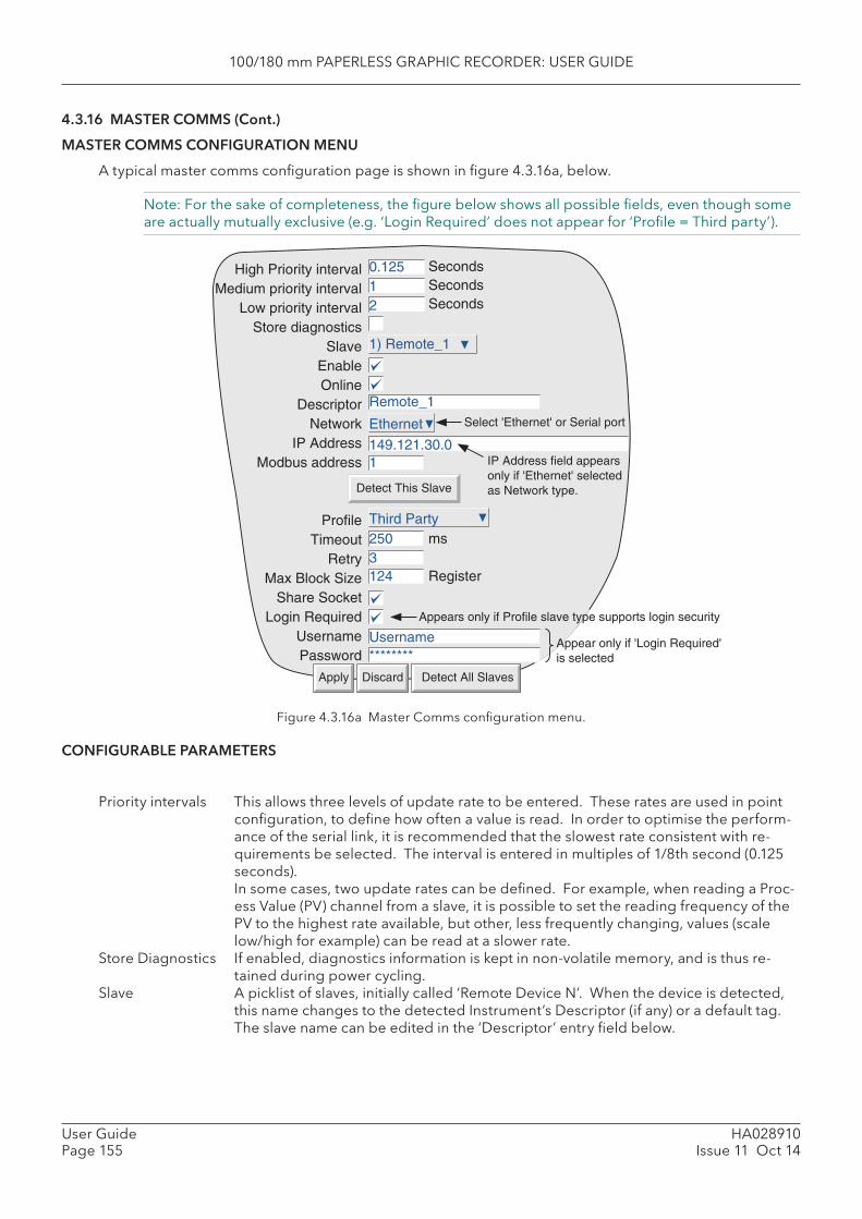
100/180 mm PAPERLESS GRAPHIC RECORDER: USER GUIDE
HA028910Issue 11 Oct 14
User GuidePage 155
4.3.16 MASTER COMMS (Cont.)
MASTER COMMS CONFIGURATION MENU
A typical master comms confi guration page is shown in fi gure 4.3.16a, below.
Note: For the sake of completeness, the fi gure below shows all possible fi elds, even though some are actually mutually exclusive (e.g. ‘Login Required’ does not appear for ‘Profi le = Third party’).
Figure 4.3.16a Master Comms confi guration menu.
CONFIGURABLE PARAMETERS
Priority intervals This allows three levels of update rate to be entered. These rates are used in point confi guration, to defi ne how often a value is read. In order to optimise the perform-ance of the serial link, it is recommended that the slowest rate consistent with re-quirements be selected. The interval is entered in multiples of 1/8th second (0.125 seconds).
In some cases, two update rates can be defi ned. For example, when reading a Proc-ess Value (PV) channel from a slave, it is possible to set the reading frequency of the PV to the highest rate available, but other, less frequently changing, values (scale low/high for example) can be read at a slower rate.
Store Diagnostics If enabled, diagnostics information is kept in non-volatile memory, and is thus re-tained during power cycling.
Slave A picklist of slaves, initially called ‘Remote Device N’. When the device is detected, this name changes to the detected Instrument’s Descriptor (if any) or a default tag. The slave name can be edited in the ‘Descriptor’ entry fi eld below.
Detect This Slave
High Priority intervalMedium priority interval
Low priority intervalStore diagnostics
SlaveEnableOnline
DescriptorNetwork
IP AddressModbus address
ProfileTimeout
RetryMax Block Size
Share SocketLogin Required
UsernamePassword
0.12512
1) Remote_1
Remote_1
149.121.30.0
Ethernet
1
Third Party2503124
ms
Register
SecondsSecondsSeconds
Detect All SlavesDiscardApply
Select 'Ethernet' or Serial port
Username********
Appears only if Profile slave type supports login security
IP Address field appearsonly if 'Ethernet' selectedas Network type.
Appear only if 'Login Required'is selected

100/180 mm PAPERLESS GRAPHIC RECORDER: USER GUIDE
User GuidePage 156
HA028910Issue 11 Oct 14
4.3.16 MASTER COMMS (Cont.)
CONFIGURABLE PARAMETERS (Cont.)
Enable If this window is not selected, none of the following fi elds appears, and the Remote Device cannot be accessed.
Online If enabled, normal communications with the slave are carried out. When disabled, the connection with the slave is terminated.
Descriptor Allows a new name for the slave device to be entered. (This name is used only within the master - it does not overwrite the Instrument Descriptor in the slave itself).
Network Select Ethernet or a Serial port. All the slaves on the link must have the same com-munications parameter values (e.g. Baud Rate) as are set for the master. See Section 4.3.15 for Serial Communications Confi guration details.
Note: Serial ports appear in the selection list only if ‘Protocol’ has been set to ‘Modbus Master’ in the Serial Comms Confi guration (section 4.3.15).
IP Address This fi eld appears only if Network = Ethernet. This must match the IP address or DNS name of the slave. For this unit, this information is to be found in Network/Address and Network/Name respectively. For other instruments, refer to the documentation supplied with those instruments.
Modbus Address For Ethernet links, Modbus addresses are associated with the IP address. This means that, for any IP address, the range of Modbus addresses used for slaves can (if required) be the same as the range used by a unit with a different IP address.
For Serial communications, each unit (including the master) must have a unique Mod-bus address.
For the unit described by this manual, the Modbus address is accessed in ‘Instru-ment’ confi guration (section 4.3.1). For other instrument the documentation sup-plied with those instruments should be referred to.
Profi le A pick list of supported instrument types. Third party is used as a default, and for non-listed instrument types. This fi eld is updated automatically if the slave is Detect-ed.
Timeout Allows a timeout period to be set for the read/write process. See ‘Retry’ below, and ‘Disable Retries’ in section 4.3.17.
Retry Allows entry of the number of times the master attempts to get a response from the slave, before aborting. If not successful, an error message appears.
Max Block size Always 124 for supported instruments, this fi eld is editable for ‘Third party’ instru-ments. The maximum block length supported by a particular instrument is found from that instrument’s documentation.
Share Socket This item appears only for slaves with Network = Ethernet. When enabled, allows a reduction in the number of links between a master and
multiple slaves. See ‘Share Socket’, below for more details. Generally, it is recom-mended that this item is left at the default for the particular slave being confi gured.
Login Required Some slaves require a user name and password to be entered before access can be gained. The user name and password set here in the master Comms confi guration must match those of the slave.
For this type of instrument, the user name is the ‘Remote user name’ and the pass-word is the ‘Remote password’ set up in the Security/Access confi guration (section 4.4.1). Password is necessary only when Modbus security disabled is not selected in ‘Instrument’ confi guration (section 4.3.1). For other types of instrument, refer to the documentation supplied with that instrument.
Username/ Password See Login Required, immediately above
DETECT THIS SLAVE
This button causes the master to search for the slave set up on this confi guration page. If the search is successful, the Remote Device name changes to the instrument name or default tag.
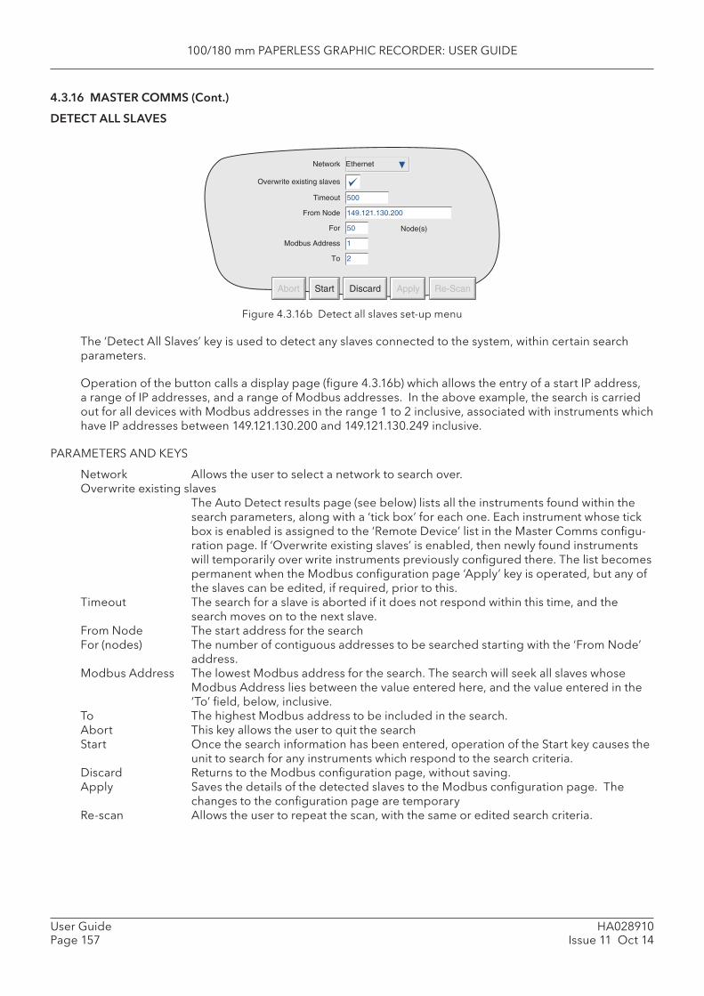
100/180 mm PAPERLESS GRAPHIC RECORDER: USER GUIDE
HA028910Issue 11 Oct 14
User GuidePage 157
4.3.16 MASTER COMMS (Cont.)
DETECT ALL SLAVES
Figure 4.3.16b Detect all slaves set-up menu
The ‘Detect All Slaves’ key is used to detect any slaves connected to the system, within certain search parameters.
Operation of the button calls a display page (fi gure 4.3.16b) which allows the entry of a start IP address, a range of IP addresses, and a range of Modbus addresses. In the above example, the search is carried out for all devices with Modbus addresses in the range 1 to 2 inclusive, associated with instruments which have IP addresses between 149.121.130.200 and 149.121.130.249 inclusive.
PARAMETERS AND KEYS
Network Allows the user to select a network to search over. Overwrite existing slaves
The Auto Detect results page (see below) lists all the instruments found within the search parameters, along with a ‘tick box’ for each one. Each instrument whose tick box is enabled is assigned to the ‘Remote Device’ list in the Master Comms confi gu-ration page. If ‘Overwrite existing slaves’ is enabled, then newly found instruments will temporarily over write instruments previously confi gured there. The list becomes permanent when the Modbus confi guration page ‘Apply’ key is operated, but any of the slaves can be edited, if required, prior to this.
Timeout The search for a slave is aborted if it does not respond within this time, and the search moves on to the next slave.
From Node The start address for the search For (nodes) The number of contiguous addresses to be searched starting with the ‘From Node’
address. Modbus Address The lowest Modbus address for the search. The search will seek all slaves whose
Modbus Address lies between the value entered here, and the value entered in the ‘To’ fi eld, below, inclusive.
To The highest Modbus address to be included in the search. Abort This key allows the user to quit the search Start Once the search information has been entered, operation of the Start key causes the
unit to search for any instruments which respond to the search criteria. Discard Returns to the Modbus confi guration page, without saving. Apply Saves the details of the detected slaves to the Modbus confi guration page. The
changes to the confi guration page are temporary Re-scan Allows the user to repeat the scan, with the same or edited search criteria.
Timeout
From Node
For
Modbus Address
To
500
149.121.130.200
50
1
2
Node(s)
Abort Start Discard Apply Re-Scan
Network Ethernet
Overwrite existing slaves
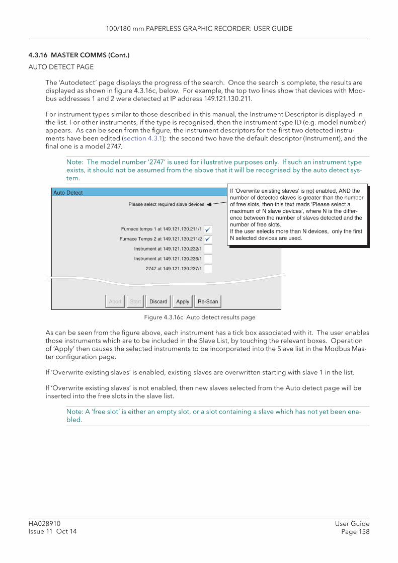
100/180 mm PAPERLESS GRAPHIC RECORDER: USER GUIDE
User GuidePage 158
HA028910Issue 11 Oct 14
4.3.16 MASTER COMMS (Cont.)
AUTO DETECT PAGE
The ‘Autodetect’ page displays the progress of the search. Once the search is complete, the results are displayed as shown in fi gure 4.3.16c, below. For example, the top two lines show that devices with Mod-bus addresses 1 and 2 were detected at IP address 149.121.130.211.
For instrument types similar to those described in this manual, the Instrument Descriptor is displayed in the list. For other instruments, if the type is recognised, then the instrument type ID (e.g. model number) appears. As can be seen from the fi gure, the instrument descriptors for the fi rst two detected instru-ments have been edited (section 4.3.1); the second two have the default descriptor (Instrument), and the fi nal one is a model 2747.
Note: The model number ‘2747’ is used for illustrative purposes only. If such an instrument type exists, it should not be assumed from the above that it will be recognised by the auto detect sys-tem.
Figure 4.3.16c Auto detect results page
As can be seen from the fi gure above, each instrument has a tick box associated with it. The user enables those instruments which are to be included in the Slave List, by touching the relevant boxes. Operation of ‘Apply’ then causes the selected instruments to be incorporated into the Slave list in the Modbus Mas-ter confi guration page.
If ‘Overwrite existing slaves’ is enabled, existing slaves are overwritten starting with slave 1 in the list.
If ‘Overwrite existing slaves’ is not enabled, then new slaves selected from the Auto detect page will be inserted into the free slots in the slave list.
Note: A ‘free slot’ is either an empty slot, or a slot containing a slave which has not yet been ena-bled.
Auto Detect
Please select required slave devices
Furnace temps 1 at 149.121.130.211/1
Furnace Temps 2 at 149.121.130.211/2
Instrument at 149.121.130.232/1
Instrument at 149.121.130.236/1
2747 at 149.121.130.237/1
Abort Start Discard Apply Re-Scan
If 'Overwrite existing slaves' is not enabled, AND thenumber of detected slaves is greater than the numberof free slots, then this text reads 'Please select amaximum of N slave devices', where N is the differ-ence between the number of slaves detected and thenumber of free slots.If the user selects more than N devices, only the firstN selected devices are used.
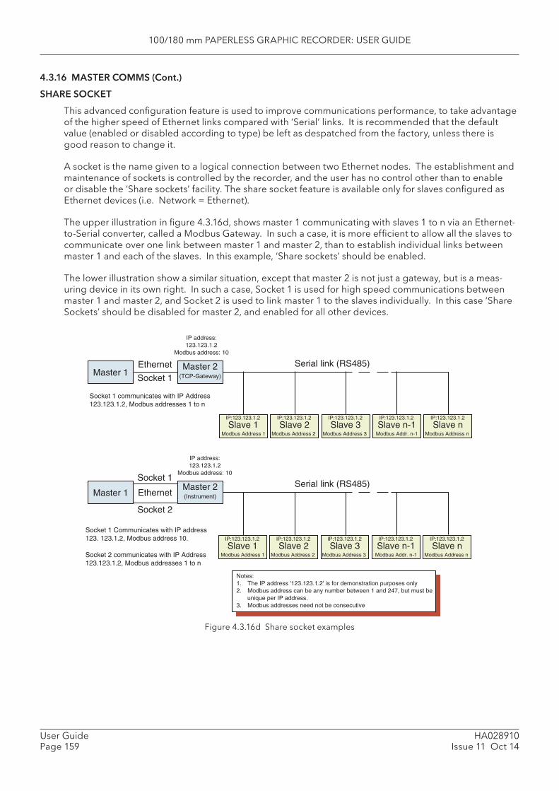
100/180 mm PAPERLESS GRAPHIC RECORDER: USER GUIDE
HA028910Issue 11 Oct 14
User GuidePage 159
4.3.16 MASTER COMMS (Cont.)
SHARE SOCKET
This advanced confi guration feature is used to improve communications performance, to take advantage of the higher speed of Ethernet links compared with ‘Serial’ links. It is recommended that the default value (enabled or disabled according to type) be left as despatched from the factory, unless there is good reason to change it.
A socket is the name given to a logical connection between two Ethernet nodes. The establishment and maintenance of sockets is controlled by the recorder, and the user has no control other than to enable or disable the ‘Share sockets’ facility. The share socket feature is available only for slaves confi gured as Ethernet devices (i.e. Network = Ethernet).
The upper illustration in fi gure 4.3.16d, shows master 1 communicating with slaves 1 to n via an Ethernet-to-Serial converter, called a Modbus Gateway. In such a case, it is more effi cient to allow all the slaves to communicate over one link between master 1 and master 2, than to establish individual links between master 1 and each of the slaves. In this example, ‘Share sockets’ should be enabled.
The lower illustration show a similar situation, except that master 2 is not just a gateway, but is a meas-uring device in its own right. In such a case, Socket 1 is used for high speed communications between master 1 and master 2, and Socket 2 is used to link master 1 to the slaves individually. In this case ‘Share Sockets’ should be disabled for master 2, and enabled for all other devices.
Figure 4.3.16d Share socket examples
Slave 1IP:123.123.1.2
Modbus Address 1
Slave 2IP:123.123.1.2
Modbus Address 2
Slave 3IP:123.123.1.2
Modbus Address 3
Slave n-1IP:123.123.1.2
Modbus Addr. n-1
Slave nIP:123.123.1.2
Modbus Address n
Master 1Ethernet
IP address:123.123.1.2
Modbus address: 10
Master 2(TCP-Gateway)
Serial link (RS485)
Notes:1. The IP address '123.123.1.2' is for demonstration purposes only2. Modbus address can be any number between 1 and 247, but must be
unique per IP address.3. Modbus addresses need not be consecutive
Master 1
Socket 1
IP address:123.123.1.2
Modbus address: 10
Master 2(Instrument)
Serial link (RS485)
Socket 2
Socket 1 Communicates with IP address123. 123.1.2, Modbus address 10.
Socket 2 communicates with IP Address123.123.1.2, Modbus addresses 1 to n
Ethernet
Socket 1
Socket 1 communicates with IP Address123.123.1.2, Modbus addresses 1 to n
Slave 1IP:123.123.1.2
Modbus Address 1
Slave 2IP:123.123.1.2
Modbus Address 2
Slave 3IP:123.123.1.2
Modbus Address 3
Slave n-1IP:123.123.1.2
Modbus Addr. n-1
Slave nIP:123.123.1.2
Modbus Address n
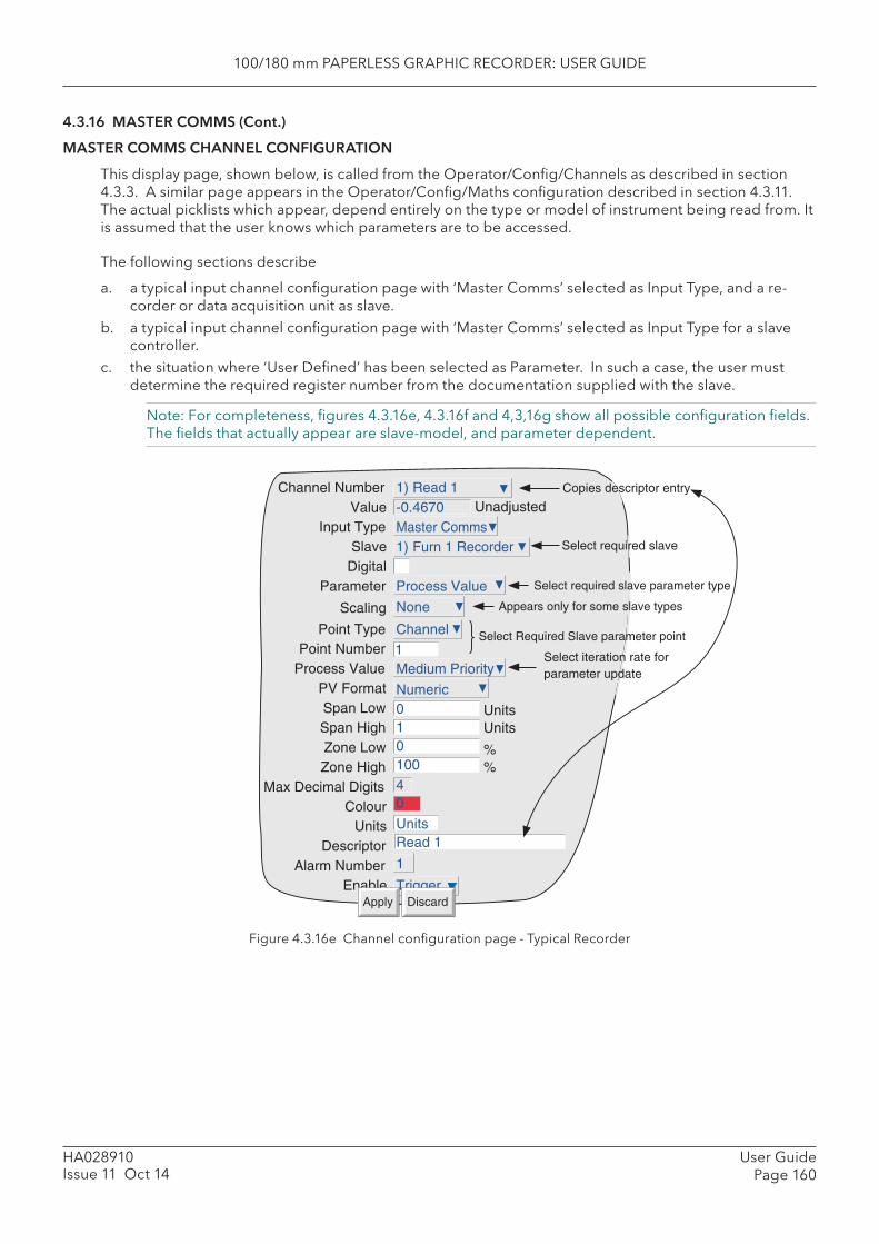
100/180 mm PAPERLESS GRAPHIC RECORDER: USER GUIDE
User GuidePage 160
HA028910Issue 11 Oct 14
4.3.16 MASTER COMMS (Cont.)
MASTER COMMS CHANNEL CONFIGURATION
This display page, shown below, is called from the Operator/Confi g/Channels as described in section 4.3.3. A similar page appears in the Operator/Confi g/Maths confi guration described in section 4.3.11. The actual picklists which appear, depend entirely on the type or model of instrument being read from. It is assumed that the user knows which parameters are to be accessed.
The following sections describe
a. a typical input channel confi guration page with ‘Master Comms’ selected as Input Type, and a re-corder or data acquisition unit as slave.
b. a typical input channel confi guration page with ‘Master Comms’ selected as Input Type for a slave controller.
c. the situation where ‘User Defi ned’ has been selected as Parameter. In such a case, the user must determine the required register number from the documentation supplied with the slave.
Note: For completeness, fi gures 4.3.16e, 4.3.16f and 4,3,16g show all possible confi guration fi elds. The fi elds that actually appear are slave-model, and parameter dependent.
Figure 4.3.16e Channel confi guration page - Typical Recorder
Channel NumberValue
Input TypeSlave
DigitalParameter
Point TypePoint Number
Process ValuePV FormatSpan LowSpan HighZone LowZone High
Max Decimal DigitsColour
UnitsDescriptor
Alarm NumberEnable
Medium Priority
Unadjusted
1
Numeric01010040
UnitsRead 1
1
TriggerDiscardApply
1) Read 1-0.4670Master Comms1) Furn 1 Recorder
Process Value
Channel
UnitsUnits
%%
Select required slave
Select required slave parameter type
Select iteration rate forparameter update
Copies descriptor entry
Scaling None
Select Required Slave parameter point
Appears only for some slave types
100/180 mm PAPERLESS GRAPHIC RECORDER: USER GUIDE
HA028910Issue 11 Oct 14
User GuidePage 161
4.3.16 MASTER COMMS (Cont.)
RECORDER/DAQ CONFIGURABLE PARAMETERS
TYPICAL RECORDER PARAMETERS
The following parameters may be accessible from a recorder or data acquisition unit, depending on model number. Figure 4.3.16e, above, refers
Notes:1. Items such as Scale, Zone and descriptor may be editable (white background) or not (grey back-
ground), depending on model.2 This description includes only those items which are unique to input channels with Input Type =
Master Comms. For other items please see section 4.3.3.
Channel Number Allows the user to select the number of the channel to be confi gured. As soon as Modbus master is selected as input type, the display changes from ‘Channel 1’ (for example) to ‘Read 1’. This legend stays as ‘Read 1’ ‘until a descriptor is entered (be-low), which immediately overwrites it.
Slave Allows the user to select (from a picklist), the slave from which data is to be retrieved. The picklist contains all the Remote Devices confi gured as slaves in the Master Comms Confi guration described above.
Digital Allows data to be read into a digital input. Parameter Allows the user to select Alarm setpoints, Process Value, Batch status (model de-
pendent) or ‘User defi ned’ to be selected. ‘User defi ned’ allows a (decimal) register address to be entered
Scaling For some slaves, scale zero (scale low) is returned as value 0 and full scale (scale high) as value 65,535 (Hex FFFF) with intermediate values having proportionate values. For example the value 15, would be represented as 32,767 (7FFF) for a channel scale 0 to 30, as would a value of 50 for a channel scaled 0 to 100, and a value of 45 for a channel scaled 30 to 60. In order to convert this reading to an understandable value, a scaling factor must be entered. If the low and high scale entries match the slave channel’s scale, the master reading will be the same as the slave’s reading.
Selecting ‘High/Low’ allows Scale low and Scale high values to be entered for the selected parameter. If ‘None’ is selected, the process value is displayed as a propor-tion of 64k.
Point type This item appears for Alarm setpoints and Process Value parameters only. Point type allows the relevant point type (i.e. input channel, maths channel, totaliser etc.) in the slave to be selected.
Point number This item appears for Alarm setpoints and Process Value parameters only. Point number allows the relevant point number in the slave to be selected.
Group Number This item appears for Parameter = ‘Batch Status’ only. Group number allows that group, the status of which is to be read, to be defi ned.
Process Value Allows one of three rates to be set for reading the Process Value. The three rates (Low, Medium and High) have the values set in the Master Comms confi guration.
Span Where the input value is scaled (see above), this ‘Span’ setting sets the Zero and Full Scale values for the channel. This is different from the situation obtaining in input channels, where span and scale have different meanings.
Remaining items are as described in Channel Confi guration in section 4.3.3.
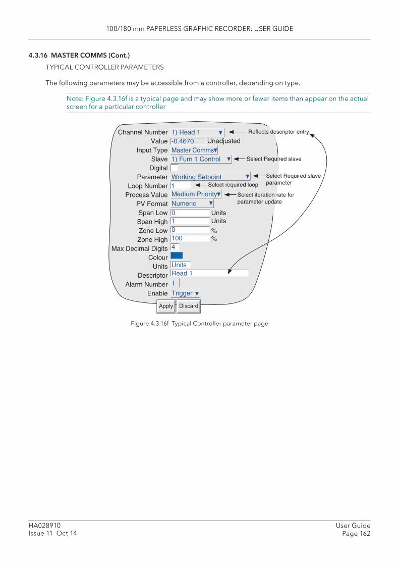
100/180 mm PAPERLESS GRAPHIC RECORDER: USER GUIDE
User GuidePage 162
HA028910Issue 11 Oct 14
4.3.16 MASTER COMMS (Cont.)
TYPICAL CONTROLLER PARAMETERS
The following parameters may be accessible from a controller, depending on type.
Note: Figure 4.3.16f is a typical page and may show more or fewer items than appear on the actual screen for a particular controller
Figure 4.3.16f Typical Controller parameter page
Medium Priority
Unadjusted
Select Required slave
1
Numeric01010040UnitsRead 1
1
Trigger
1) Read 1-0.4670Master Comms1) Furn 1 Control
Working Setpoint Select Required slaveparameterSelect required loop
Select iteration rate forparameter update
UnitsUnits
%%
Reflects descriptor entryChannel NumberValue
Input TypeSlaveDigital
ParameterLoop Number
Process ValuePV FormatSpan LowSpan HighZone LowZone High
Max Decimal DigitsColour
UnitsDescriptor
Alarm NumberEnable
DiscardApply
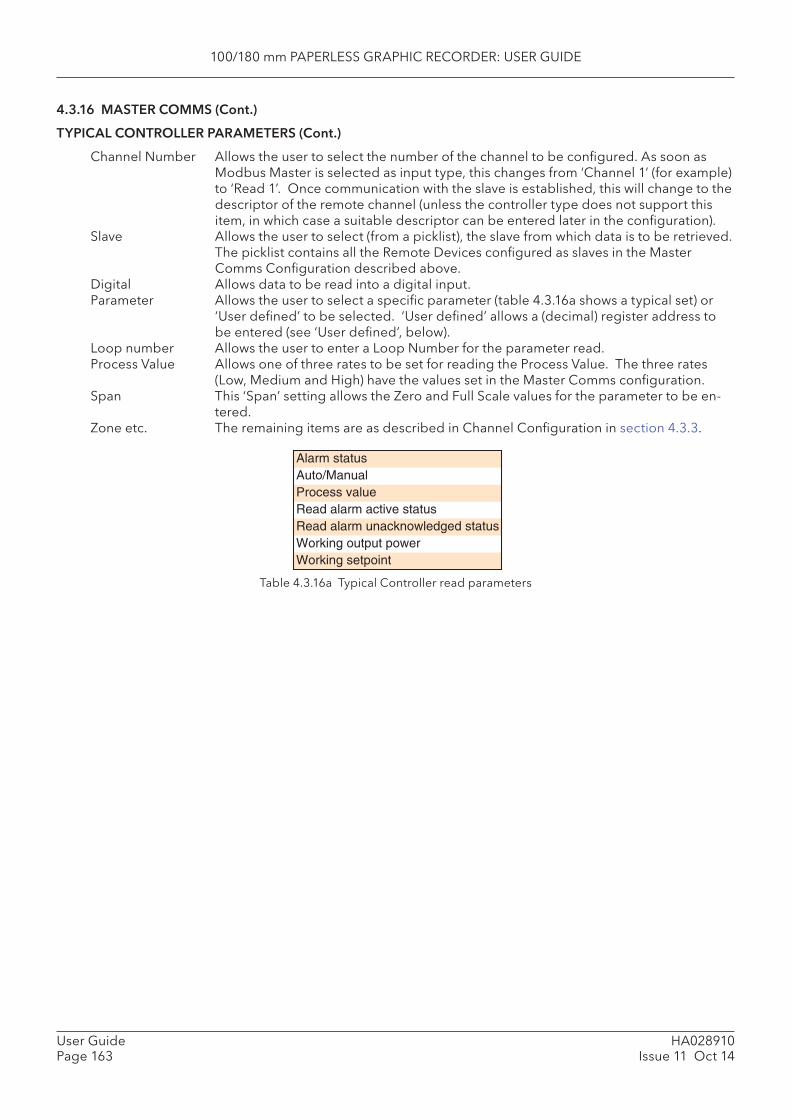
100/180 mm PAPERLESS GRAPHIC RECORDER: USER GUIDE
HA028910Issue 11 Oct 14
User GuidePage 163
4.3.16 MASTER COMMS (Cont.)
TYPICAL CONTROLLER PARAMETERS (Cont.)
Channel Number Allows the user to select the number of the channel to be confi gured. As soon as Modbus Master is selected as input type, this changes from ‘Channel 1’ (for example) to ‘Read 1’. Once communication with the slave is established, this will change to the descriptor of the remote channel (unless the controller type does not support this item, in which case a suitable descriptor can be entered later in the confi guration).
Slave Allows the user to select (from a picklist), the slave from which data is to be retrieved. The picklist contains all the Remote Devices confi gured as slaves in the Master Comms Confi guration described above.
Digital Allows data to be read into a digital input. Parameter Allows the user to select a specifi c parameter (table 4.3.16a shows a typical set) or
‘User defi ned’ to be selected. ‘User defi ned’ allows a (decimal) register address to be entered (see ‘User defi ned’, below).
Loop number Allows the user to enter a Loop Number for the parameter read. Process Value Allows one of three rates to be set for reading the Process Value. The three rates
(Low, Medium and High) have the values set in the Master Comms confi guration. Span This ‘Span’ setting allows the Zero and Full Scale values for the parameter to be en-
tered.Zone etc. The remaining items are as described in Channel Confi guration in section 4.3.3.
Table 4.3.16a Typical Controller read parameters
Alarm statusAuto/ManualProcess valueRead alarm active statusRead alarm unacknowledged statusWorking output powerWorking setpoint
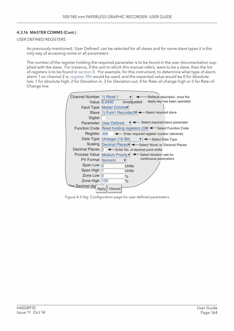
100/180 mm PAPERLESS GRAPHIC RECORDER: USER GUIDE
User GuidePage 164
HA028910Issue 11 Oct 14
4.3.16 MASTER COMMS (Cont.)
USER DEFINED REGISTERS
As previously mentioned, ‘User Defi ned’ can be selected for all slaves and for some slave types it is the only way of accessing some or all parameters.
The number of the register holding the required parameter is to be found in the user documentation sup-plied with the slave. For instance, if the unit to which this manual refers, were to be a slave, then the list of registers is to be found in section 8. For example, for this instrument, to determine what type of alarm, alarm 1 on channel 2 is, register 396 would be used, and the expected value would be 0 for Absolute low, 1 for absolute high, 2 for Deviation in, 3 for Deviation out, 4 for Rate-of-change high or 5 for Rate-of-Change low.
Figure 4.3.16g Confi guration page for user defi ned parameters
Channel NumberValue
Input TypeSlaveDigital
ParameterFunction Code
RegisterData Type
ScalingDecimal PlacesProcess Value
PV FormatSpan LowSpan HighZone LowZone High
Decimal digits
UInteger (16 Bit)
Unadjusted
Select required slave
Decimal Places
010100
1) Read 10.0400Master Comms1) Furn1 Recorder2
User Defined Select required slave parameter
Select iteration rate forcontinuous parameters
UnitsUnits
%%
Read holding registers (3)
2Medium PriorityNumeric
Select 'None' or 'Decimal Places'
Select Data Type
Select Function Code
Enter No. of decimal point shifts
396 Enter required register number (decimal)
Reflects descriptor, once theApply key has been operated.
4DiscardApply
100/180 mm PAPERLESS GRAPHIC RECORDER: USER GUIDE
HA028910Issue 11 Oct 14
User GuidePage 165
4.3.16 MASTER COMMS (Cont.)
CONFIGURABLE PARAMETERS
This section defi nes those parameters which are unique to user defi ned registers.
Value Shows the value returned from the selected register, as modifi ed by the scaling fac-tor (if any).
Function Code Allows Modbus function code 03 or 04 to be selected. In some implementations, the functions of the two codes are identical. In others, the codes have different func-tions. See the documentation supplied with the slave for a list of supported Modbus codes. For this instrument see section 8.2.1.
Register A decimal number representing the required parameter’s location in the slave’s Modbus Register map. This information must be determined from the documenta-tion supplied with the slave. For this instrument, section 8.4 contains listings for a number of instrument, groups, and input channels. For details of maths, totalisers etc., refer to the relevant option description.
Data Type Select a suitable data type for the selected parameter (again from the slave docu-mentation). For this instrument, a list of relevant data types is given in section 8.4.
Scaling Whether Scaling appears or not is Model and Parameter dependent. If scaling is re-quired, the choice may be ‘Decimal Places, or High/Low, again according to Model.
Decimal PlacesAllows a dividing factor to be entered. An entry of 1, divides the returned value by 10. An entry of 2, divides by 100 etc. for successful implementation, there must be a suffi cient number of decimal places defi ned in the ‘Max Decimal Digits’ confi gura-tion fi eld for the value to be displayed with the required precision. ‘None’ leaves the returned value unchanged.
For some slaves, scale zero (scale low) is returned as value 0 and full scale (scale high) as value 65,535 (Hex FFFF) with intermediate values having proportionate values. For example the value 15, would be represented as 32,767 (7FFF) for a channel scale 0 to 30, as would a value of 50 for a channel scaled 0 to 100, and a value of 45 for a channel scaled 30 to 60. In order to convert this reading to an understandable value, a scaling factor must be entered. If the low and high scale entries match the slave channel’s scale, the master reading will be the same as the slave’s reading.
Selecting ‘High/Low’ allows Scale low and Scale high values to be entered for the selected parameter.If ‘None’ is selected, the process value is displayed as a proportion of 65,535.
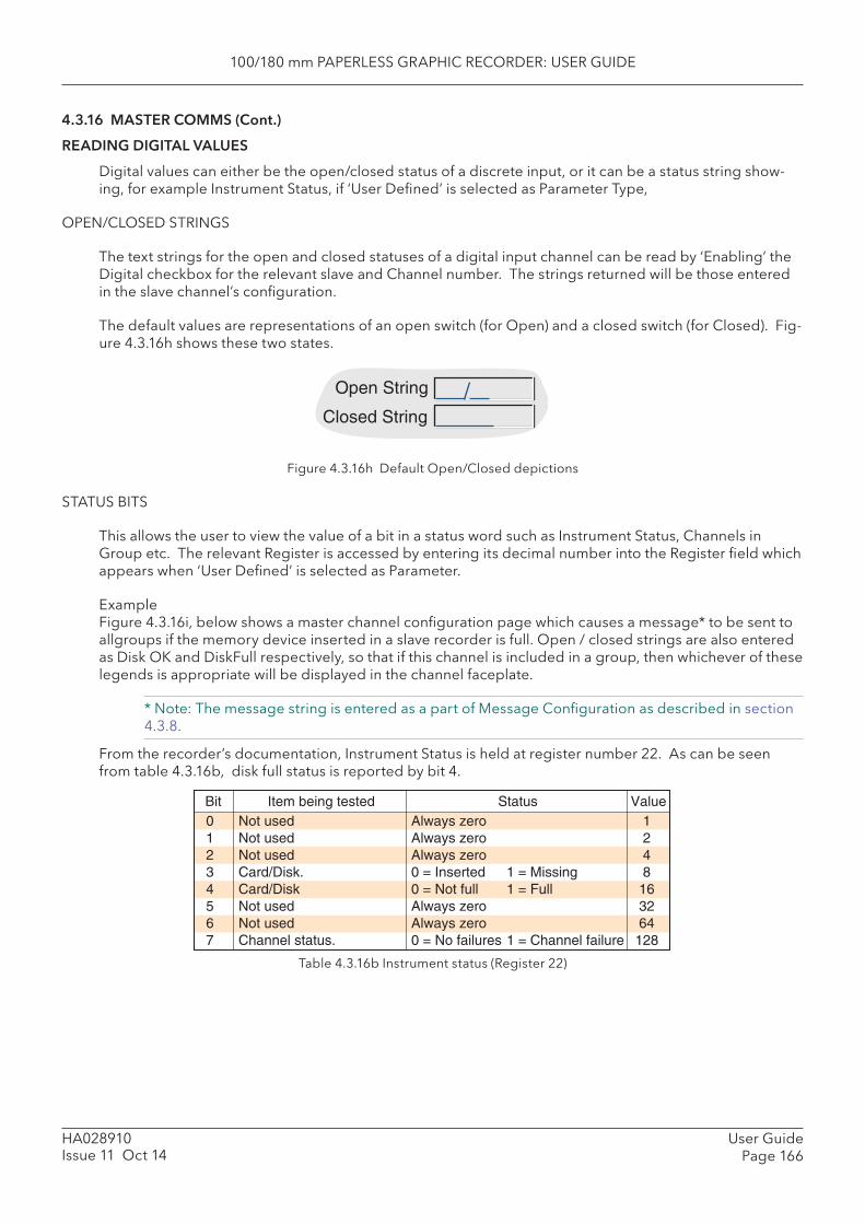
100/180 mm PAPERLESS GRAPHIC RECORDER: USER GUIDE
User GuidePage 166
HA028910Issue 11 Oct 14
4.3.16 MASTER COMMS (Cont.)
READING DIGITAL VALUES
Digital values can either be the open/closed status of a discrete input, or it can be a status string show-ing, for example Instrument Status, if ‘User Defi ned’ is selected as Parameter Type,
OPEN/CLOSED STRINGS
The text strings for the open and closed statuses of a digital input channel can be read by ‘Enabling’ the Digital checkbox for the relevant slave and Channel number. The strings returned will be those entered in the slave channel’s confi guration.
The default values are representations of an open switch (for Open) and a closed switch (for Closed). Fig-ure 4.3.16h shows these two states.
Figure 4.3.16h Default Open/Closed depictions
STATUS BITS
This allows the user to view the value of a bit in a status word such as Instrument Status, Channels in Group etc. The relevant Register is accessed by entering its decimal number into the Register fi eld which appears when ‘User Defi ned’ is selected as Parameter.
ExampleFigure 4.3.16i, below shows a master channel confi guration page which causes a message* to be sent to allgroups if the memory device inserted in a slave recorder is full. Open / closed strings are also entered as Disk OK and DiskFull respectively, so that if this channel is included in a group, then whichever of these legends is appropriate will be displayed in the channel faceplate.
* Note: The message string is entered as a part of Message Confi guration as described in section 4.3.8.
From the recorder’s documentation, Instrument Status is held at register number 22. As can be seen from table 4.3.16b, disk full status is reported by bit 4.
Open String
Closed String
Table 4.3.16b Instrument status (Register 22)
0 Not used Always zero 11 Not used Always zero 22 Not used Always zero 43 Card/Disk. 0 = Inserted 1 = Missing 84 Card/Disk 0 = Not full 1 = Full 165 Not used Always zero 326 Not used Always zero 647 Channel status. 0 = No failures 1 = Channel failure 128
Bit Item being tested Status Value
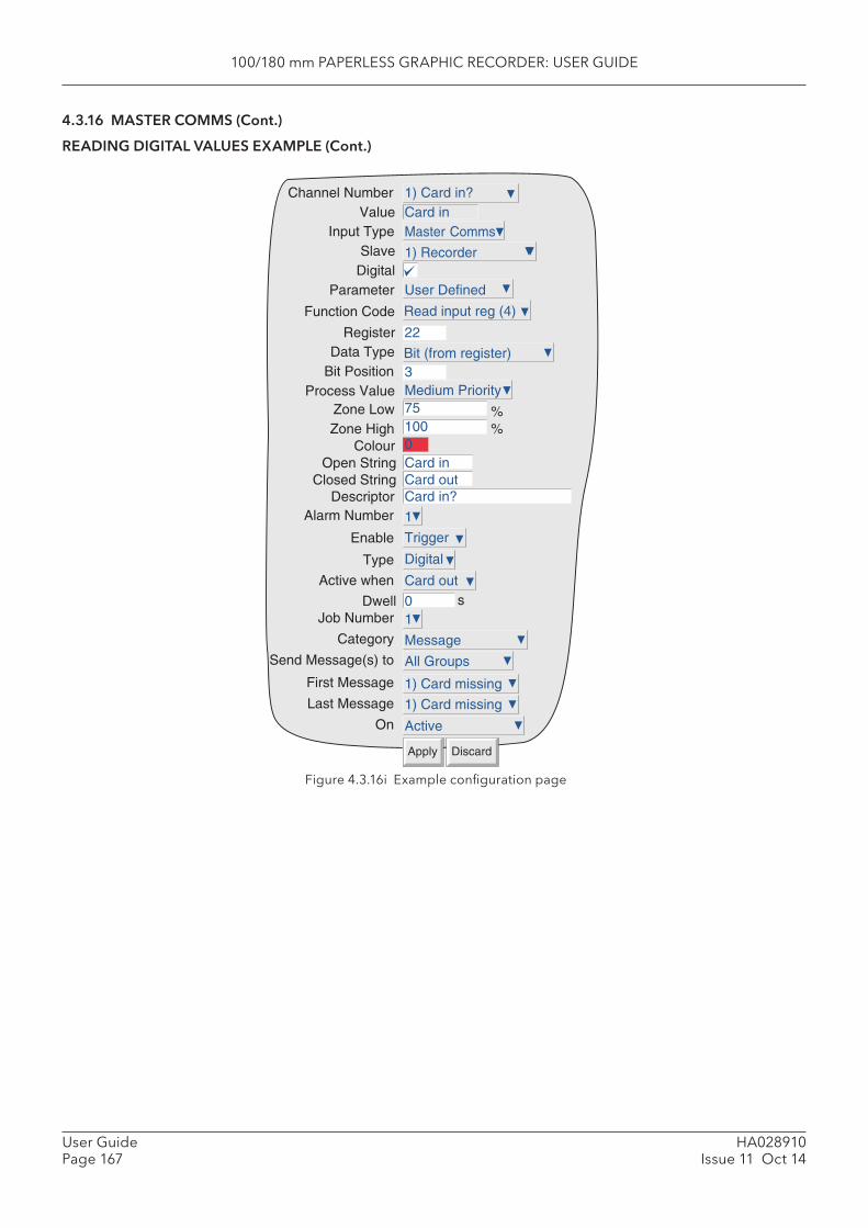
100/180 mm PAPERLESS GRAPHIC RECORDER: USER GUIDE
HA028910Issue 11 Oct 14
User GuidePage 167
4.3.16 MASTER COMMS (Cont.)
READING DIGITAL VALUES EXAMPLE (Cont.)
Figure 4.3.16i Example confi guration page
Channel NumberValue
Input TypeSlave
DigitalParameter
RegisterData Type
Bit PositionProcess Value
Zone LowZone High
ColourOpen String
DescriptorAlarm Number
751000Card in
1
Trigger
DiscardApply
1) Card in?Card inMaster Comms
1) Recorder
User Defined
22
%%
Function Code Read input reg (4)
Bit (from register)
Medium Priority3
Card in?Closed String Card out
Digital
Card out
Dwell 0 sJob Number 1
Enable
Type
Active when
Category MessageSend Message(s) to All Groups
First Message 1) Card missingLast Message
On Active
1) Card missing
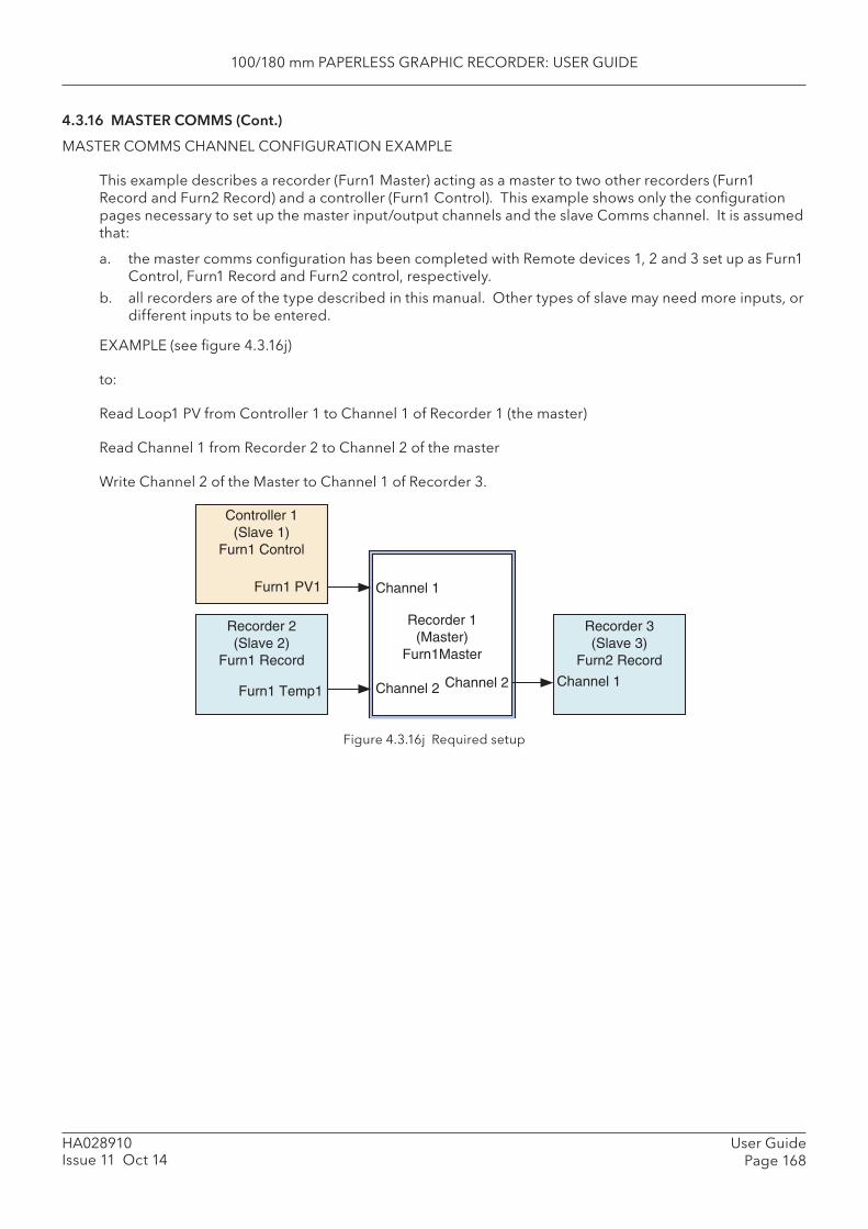
100/180 mm PAPERLESS GRAPHIC RECORDER: USER GUIDE
User GuidePage 168
HA028910Issue 11 Oct 14
4.3.16 MASTER COMMS (Cont.)
MASTER COMMS CHANNEL CONFIGURATION EXAMPLE
This example describes a recorder (Furn1 Master) acting as a master to two other recorders (Furn1 Record and Furn2 Record) and a controller (Furn1 Control). This example shows only the confi guration pages necessary to set up the master input/output channels and the slave Comms channel. It is assumed that:
a. the master comms confi guration has been completed with Remote devices 1, 2 and 3 set up as Furn1 Control, Furn1 Record and Furn2 control, respectively.
b. all recorders are of the type described in this manual. Other types of slave may need more inputs, or different inputs to be entered.
EXAMPLE (see fi gure 4.3.16j)
to:
Read Loop1 PV from Controller 1 to Channel 1 of Recorder 1 (the master)
Read Channel 1 from Recorder 2 to Channel 2 of the master
Write Channel 2 of the Master to Channel 1 of Recorder 3.
Figure 4.3.16j Required setup
Controller 1(Slave 1)
Furn1 Control
Furn1 PV1
Recorder 3(Slave 3)
Furn2 Record
Channel 1
Recorder 2(Slave 2)
Furn1 Record
Furn1 Temp1
Recorder 1(Master)
Furn1Master
Channel 1
Channel 2Channel 2
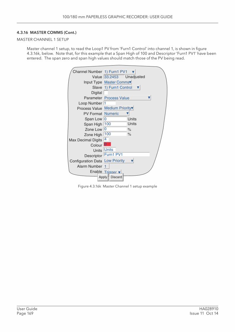
100/180 mm PAPERLESS GRAPHIC RECORDER: USER GUIDE
HA028910Issue 11 Oct 14
User GuidePage 169
4.3.16 MASTER COMMS (Cont.)
MASTER CHANNEL 1 SETUP
Master channel 1 setup, to read the Loop1 PV from ‘Furn1 Control’ into channel 1, is shown in fi gure 4.3.16k, below. Note that, for this example that a Span High of 100 and Descriptor ‘Furn1 PV1’ have been entered. The span zero and span high values should match those of the PV being read.
Figure 4.3.16k Master Channel 1 setup example
Medium Priority
Unadjusted
1
Numeric
Low Priority
0100010040UnitsFurn1 PV1
1
Trigger
1) Furn1 PV133.2453Master Comms1) Furn1 Control
Process Value
UnitsUnits
%%
Channel NumberValue
Input TypeSlaveDigital
ParameterLoop Number
Process ValuePV FormatSpan LowSpan HighZone LowZone High
Max Decimal DigitsColour
UnitsDescriptor
Configuration DataAlarm Number
EnableDiscardApply
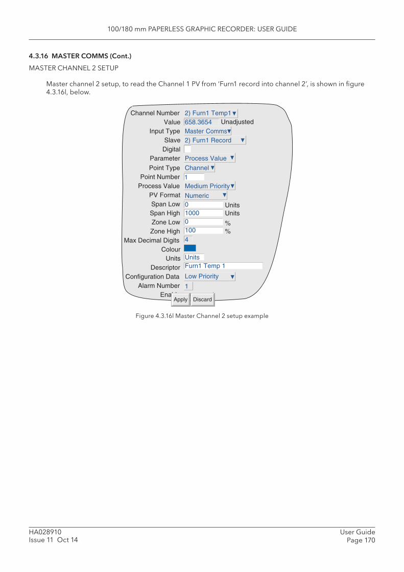
100/180 mm PAPERLESS GRAPHIC RECORDER: USER GUIDE
User GuidePage 170
HA028910Issue 11 Oct 14
4.3.16 MASTER COMMS (Cont.)
MASTER CHANNEL 2 SETUP
Master channel 2 setup, to read the Channel 1 PV from ‘Furn1 record into channel 2’, is shown in fi gure 4.3.16l, below.
Figure 4.3.16l Master Channel 2 setup example
Channel NumberValue
Input TypeSlave
DigitalParameter
Point TypePoint Number
Process ValuePV FormatSpan LowSpan HighZone LowZone High
Max Decimal DigitsColour
UnitsDescriptor
Configuration DataAlarm Number
Enable
Medium Priority
Unadjusted
1
Numeric
Low Priority
01000010041
UnitsFurn1 Temp 1
1
TriggerDiscardApply
2) Furn1 Temp1658.3654Master Comms2) Furn1 Record
Process Value
Channel
UnitsUnits
%%
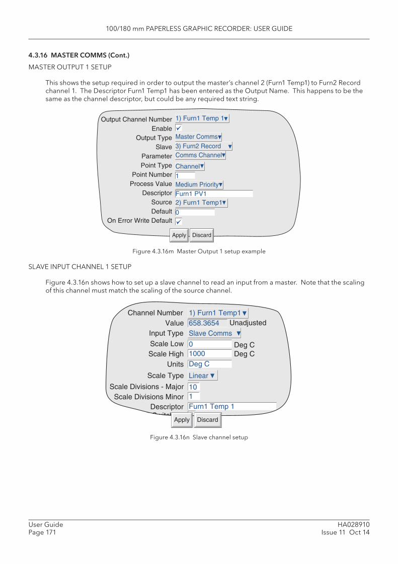
100/180 mm PAPERLESS GRAPHIC RECORDER: USER GUIDE
HA028910Issue 11 Oct 14
User GuidePage 171
4.3.16 MASTER COMMS (Cont.)
MASTER OUTPUT 1 SETUP
This shows the setup required in order to output the master’s channel 2 (Furn1 Temp1) to Furn2 Record channel 1. The Descriptor Furn1 Temp1 has been entered as the Output Name. This happens to be the same as the channel descriptor, but could be any required text string.
Figure 4.3.16m Master Output 1 setup example
SLAVE INPUT CHANNEL 1 SETUP
Figure 4.3.16n shows how to set up a slave channel to read an input from a master. Note that the scaling of this channel must match the scaling of the source channel.
Output Channel NumberEnable
Output TypeSlave
ParameterPoint Type
Point NumberProcess Value
DescriptorSourceDefault
On Error Write Default
1) Furn1 Temp 1
DiscardApply
Master Comms3) Furn2 RecordComms Channel
Channel
Medium Priority
2) Furn1 Temp1
0
1
Furn1 PV1
Figure 4.3.16n Slave channel setup
Channel NumberValue
Input Type
Scale LowScale High
Unadjusted
01000
1) Furn1 Temp1658.3654Slave Comms
Deg CDeg C
Units Deg C
Scale Type Linear
Scale Divisions - MajorScale Divisions Minor
101
Descriptor Furn1 Temp 1A/B Switching
DiscardApply
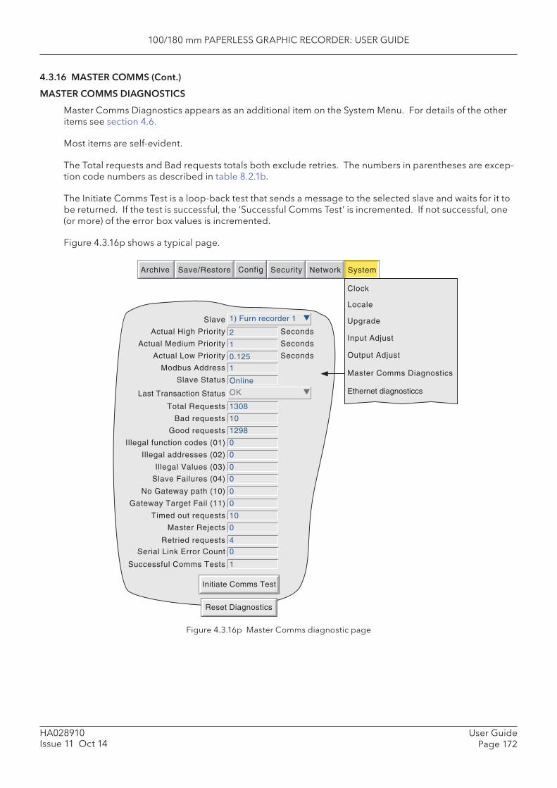
100/180 mm PAPERLESS GRAPHIC RECORDER: USER GUIDE
User GuidePage 172
HA028910Issue 11 Oct 14
4.3.16 MASTER COMMS (Cont.)
MASTER COMMS DIAGNOSTICS
Master Comms Diagnostics appears as an additional item on the System Menu. For details of the other items see section 4.6.
Most items are self-evident.
The Total requests and Bad requests totals both exclude retries. The numbers in parentheses are excep-tion code numbers as described in table 8.2.1b.
The Initiate Comms Test is a loop-back test that sends a message to the selected slave and waits for it to be returned. If the test is successful, the ‘Successful Comms Test’ is incremented. If not successful, one (or more) of the error box values is incremented.
Figure 4.3.16p shows a typical page.
Figure 4.3.16p Master Comms diagnostic page
Slave 1) Furn recorder 1
Reset Diagnostics
Initiate Comms Test
Archive SystemSave/Restore Config Security Network
Clock
Locale
Upgrade
Input Adjust
Output Adjust
Actual High Priority
Modbus Address
Slave Status
Seconds
Actual Medium Priority
Actual Low Priority
Seconds
Seconds
2
1
0.125
1
Online
Last Transaction Status OK
Total Requests 1308
Bad requests 10
Good requests 1298
Illegal function codes (01) 0
Illegal addresses (02) 0
Illegal Values (03) 0
No Gateway path (10) 0
Gateway Target Fail (11) 0
Timed out requests 10
Retried requests 4
Serial Link Error Count 0
Successful Comms Tests 1
Slave Failures (04) 0
Master Rejects 0
Master Comms Diagnostics
Ethernet diagnosticcs
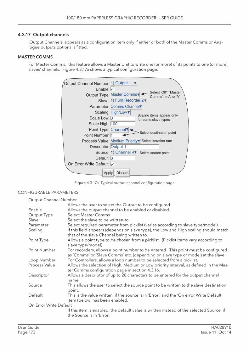
100/180 mm PAPERLESS GRAPHIC RECORDER: USER GUIDE
HA028910Issue 11 Oct 14
User GuidePage 173
4.3.17 Output channels
‘Output Channels’ appears as a confi guration item only if either or both of the Master Comms or Ana-logue outputs options is fi tted.
MASTER COMMS
For Master Comms, this feature allows a Master Unit to write one (or more) of its points to one (or more) slaves’ channels. Figure 4.3.17a shows a typical confi guration page.
Figure 4.3.17a Typical output channel confi guration page
CONFIGURABLE PARAMETERS
Output Channel NumberAllows the user to select the Output to be confi gured.
Enable Allows the output channel to be enabled or disabled. Output Type Select Master Comms Slave Select the slave to be written-to. Parameter Select required parameter from picklist (varies according to slave type/model) Scaling If this fi eld appears (depends on slave type), the Low and High scaling should match
that of the slave Channel being written to. Point Type Allows a point type to be chosen from a picklist. (Picklist items vary according to
slave type/model) Point Number For recorders, allows a point number to be entered. This point must be confi gured
as ‘Comms’ or ‘Slave Comms’ etc. (depending on slave type or model) at the slave. Loop Number For Controllers, allows a loop number to be selected from a picklist. Process Value Allows the selection of High, Medium or Low priority interval, as defi ned in the Mas-
ter Comms confi guration page in section 4.3.16. Descriptor Allows a descriptor of up to 20 characters to be entered for the output channel
name. Source This allows the user to select the source point to be written to the slave destination
point. Default This is the value written, if the source is in ‘Error’, and the ‘On error Write Default’
item (below) has been enabled. On Error Write Default
If this item is enabled, the default value is written instead of the selected Source, if the Source is in ‘Error’.
Output Channel NumberEnable
Output TypeSlave
ParameterScaling
Scale LowScale HighPoint Type
Point NumberProcess Value
DescriptorSourceDefault
On Error Write Default
1) Output 1
DiscardApply
Master Comms1) Furn Recorder 2
Comms Channel
Channel
Medium Priority
1) Channel 4
High/Low0100
0
1
Output 1
Scaling items appear onlyfor some slave types
Select destination point
Select iteration rate
Select source point
Select 'Off'', 'MasterComms', 'mA' or 'V'
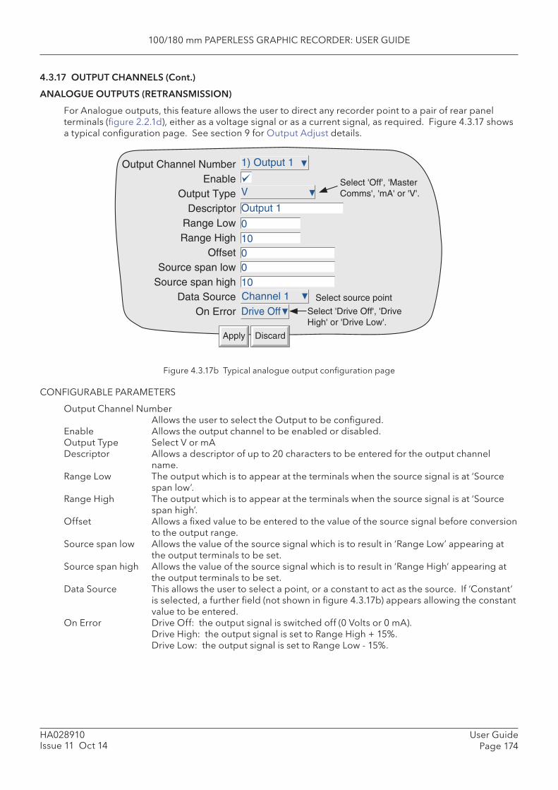
100/180 mm PAPERLESS GRAPHIC RECORDER: USER GUIDE
User GuidePage 174
HA028910Issue 11 Oct 14
4.3.17 OUTPUT CHANNELS (Cont.)
ANALOGUE OUTPUTS (RETRANSMISSION)
For Analogue outputs, this feature allows the user to direct any recorder point to a pair of rear panel terminals (fi gure 2.2.1d), either as a voltage signal or as a current signal, as required. Figure 4.3.17 shows a typical confi guration page. See section 9 for Output Adjust details.
Figure 4.3.17b Typical analogue output confi guration page
CONFIGURABLE PARAMETERS
Output Channel NumberAllows the user to select the Output to be confi gured.
Enable Allows the output channel to be enabled or disabled. Output Type Select V or mA Descriptor Allows a descriptor of up to 20 characters to be entered for the output channel
name. Range Low The output which is to appear at the terminals when the source signal is at ‘Source
span low’.Range High The output which is to appear at the terminals when the source signal is at ‘Source
span high’. Offset Allows a fi xed value to be entered to the value of the source signal before conversion
to the output range. Source span low Allows the value of the source signal which is to result in ‘Range Low’ appearing at
the output terminals to be set.Source span high Allows the value of the source signal which is to result in ‘Range High’ appearing at
the output terminals to be set. Data Source This allows the user to select a point, or a constant to act as the source. If ‘Constant’
is selected, a further fi eld (not shown in fi gure 4.3.17b) appears allowing the constant value to be entered.
On Error Drive Off: the output signal is switched off (0 Volts or 0 mA). Drive High: the output signal is set to Range High + 15%. Drive Low: the output signal is set to Range Low - 15%.
Output Channel NumberEnable
Output TypeDescriptor
Range LowRange High
OffsetSource span low
Source span highData Source
On Error
1) Output 1
DiscardApply
V
Drive OffChannel 1
00
Output 1
Select source point
Select 'Off', 'MasterComms', 'mA' or 'V'.
010
10
Select 'Drive Off', 'DriveHigh' or 'Drive Low'.
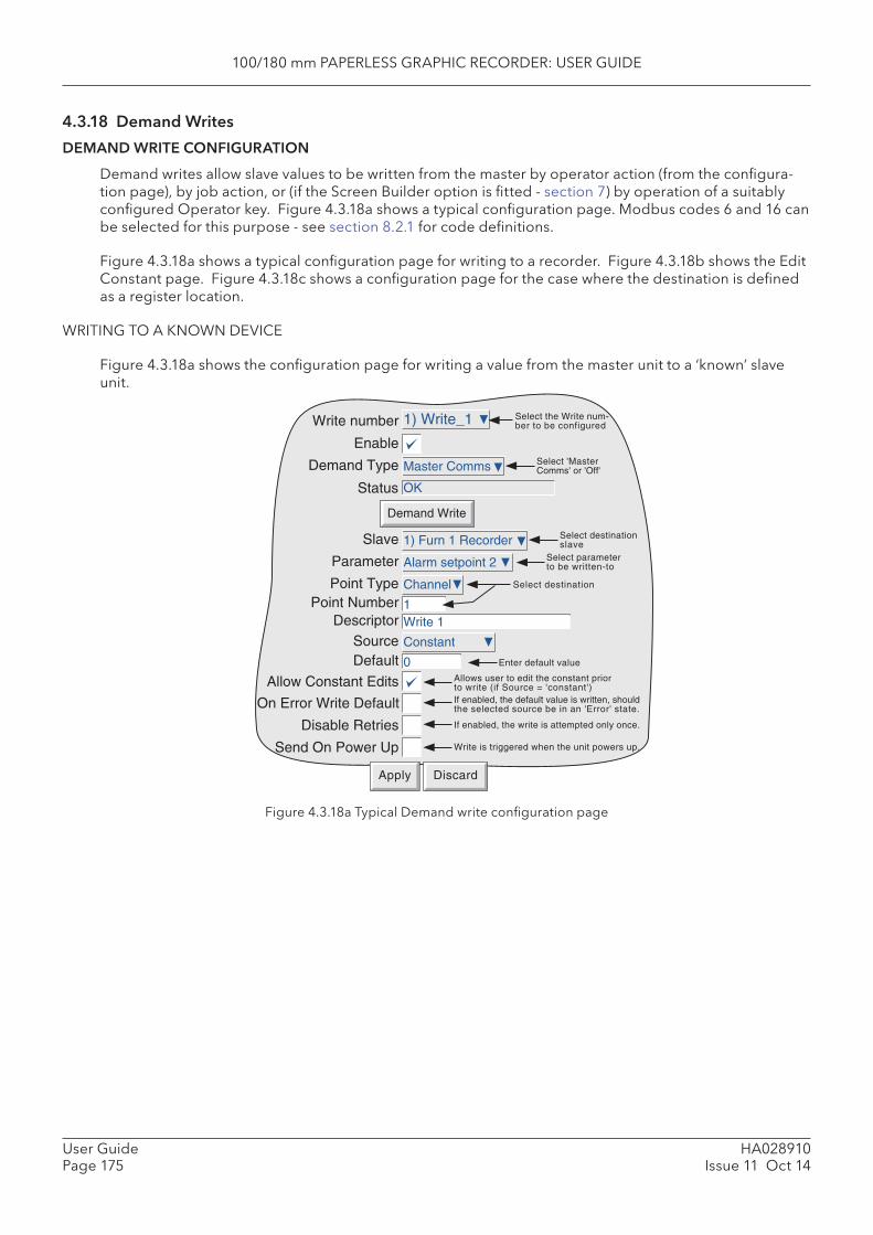
100/180 mm PAPERLESS GRAPHIC RECORDER: USER GUIDE
HA028910Issue 11 Oct 14
User GuidePage 175
4.3.18 Demand Writes
DEMAND WRITE CONFIGURATION
Demand writes allow slave values to be written from the master by operator action (from the confi gura-tion page), by job action, or (if the Screen Builder option is fi tted - section 7) by operation of a suitably confi gured Operator key. Figure 4.3.18a shows a typical confi guration page. Modbus codes 6 and 16 can be selected for this purpose - see section 8.2.1 for code defi nitions.
Figure 4.3.18a shows a typical confi guration page for writing to a recorder. Figure 4.3.18b shows the Edit Constant page. Figure 4.3.18c shows a confi guration page for the case where the destination is defi ned as a register location.
WRITING TO A KNOWN DEVICE
Figure 4.3.18a shows the confi guration page for writing a value from the master unit to a ‘known’ slave unit.
Figure 4.3.18a Typical Demand write confi guration page
Enable
Demand Type
Status
Master Comms
Apply Discard
Write number 1) Write_1 Select the Write num-ber to be configured
Select 'MasterComms' or 'Off'
OK
Demand Write
Slave 1) Furn 1 Recorder Select destinationslave
Parameter Alarm setpoint 2 Select parameterto be written-to
Point Type Channel Select destination
Point Number 1Descriptor Write 1
Source Constant
Enter default valueDefault 0
Allow Constant Edits
Disable Retries
Send On Power Up
On Error Write Default
Allows user to edit the constant priorto write (if Source = 'constant')If enabled, the default value is written, shouldthe selected source be in an 'Error' state.
If enabled, the write is attempted only once.
Write is triggered when the unit powers up.
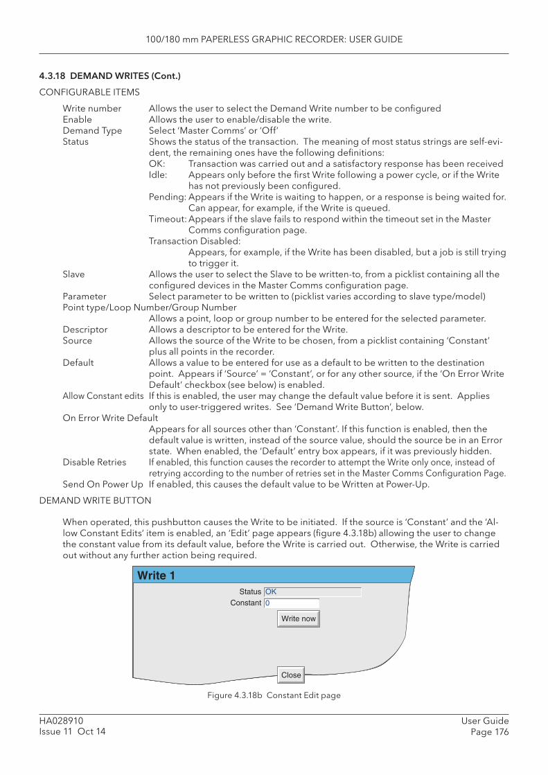
100/180 mm PAPERLESS GRAPHIC RECORDER: USER GUIDE
User GuidePage 176
HA028910Issue 11 Oct 14
4.3.18 DEMAND WRITES (Cont.)
CONFIGURABLE ITEMS
Write number Allows the user to select the Demand Write number to be confi gured Enable Allows the user to enable/disable the write. Demand Type Select ‘Master Comms’ or ‘Off’ Status Shows the status of the transaction. The meaning of most status strings are self-evi-
dent, the remaining ones have the following defi nitions: OK: Transaction was carried out and a satisfactory response has been received Idle: Appears only before the fi rst Write following a power cycle, or if the Write
has not previously been confi gured. Pending: Appears if the Write is waiting to happen, or a response is being waited for.
Can appear, for example, if the Write is queued. Timeout: Appears if the slave fails to respond within the timeout set in the Master
Comms confi guration page. Transaction Disabled:
Appears, for example, if the Write has been disabled, but a job is still trying to trigger it.
Slave Allows the user to select the Slave to be written-to, from a picklist containing all the confi gured devices in the Master Comms confi guration page.
Parameter Select parameter to be written to (picklist varies according to slave type/model) Point type/Loop Number/Group Number
Allows a point, loop or group number to be entered for the selected parameter. Descriptor Allows a descriptor to be entered for the Write. Source Allows the source of the Write to be chosen, from a picklist containing ‘Constant’
plus all points in the recorder. Default Allows a value to be entered for use as a default to be written to the destination
point. Appears if ‘Source’ = ‘Constant’, or for any other source, if the ‘On Error Write Default’ checkbox (see below) is enabled.
Allow Constant edits If this is enabled, the user may change the default value before it is sent. Applies only to user-triggered writes. See ‘Demand Write Button’, below.
On Error Write Default Appears for all sources other than ‘Constant’. If this function is enabled, then the default value is written, instead of the source value, should the source be in an Error state. When enabled, the ‘Default’ entry box appears, if it was previously hidden.
Disable Retries If enabled, this function causes the recorder to attempt the Write only once, instead of retrying according to the number of retries set in the Master Comms Confi guration Page.
Send On Power Up If enabled, this causes the default value to be Written at Power-Up.
DEMAND WRITE BUTTON
When operated, this pushbutton causes the Write to be initiated. If the source is ‘Constant’ and the ‘Al-low Constant Edits’ item is enabled, an ‘Edit’ page appears (fi gure 4.3.18b) allowing the user to change the constant value from its default value, before the Write is carried out. Otherwise, the Write is carried out without any further action being required.
Figure 4.3.18b Constant Edit page
Write 1OK
0
Write now
Close
StatusConstant
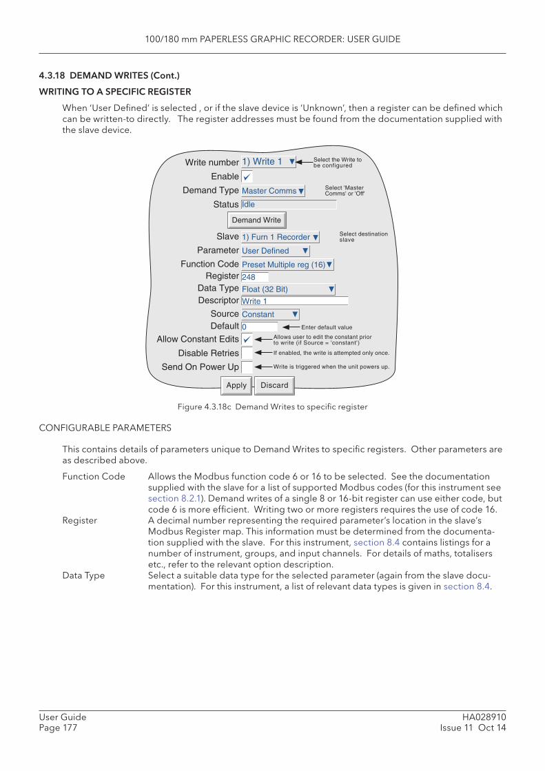
100/180 mm PAPERLESS GRAPHIC RECORDER: USER GUIDE
HA028910Issue 11 Oct 14
User GuidePage 177
4.3.18 DEMAND WRITES (Cont.)
WRITING TO A SPECIFIC REGISTER
When ‘User Defi ned’ is selected , or if the slave device is ‘Unknown’, then a register can be defi ned which can be written-to directly. The register addresses must be found from the documentation supplied with the slave device.
Figure 4.3.18c Demand Writes to specifi c register
CONFIGURABLE PARAMETERS
This contains details of parameters unique to Demand Writes to specifi c registers. Other parameters are as described above.
Function Code Allows the Modbus function code 6 or 16 to be selected. See the documentation supplied with the slave for a list of supported Modbus codes (for this instrument see section 8.2.1). Demand writes of a single 8 or 16-bit register can use either code, but code 6 is more effi cient. Writing two or more registers requires the use of code 16.
Register A decimal number representing the required parameter’s location in the slave’s Modbus Register map. This information must be determined from the documenta-tion supplied with the slave. For this instrument, section 8.4 contains listings for a number of instrument, groups, and input channels. For details of maths, totalisers etc., refer to the relevant option description.
Data Type Select a suitable data type for the selected parameter (again from the slave docu-mentation). For this instrument, a list of relevant data types is given in section 8.4.
Enable
Demand Type
Status
Master Comms
Apply Discard
Write number 1) Write 1 Select the Write tobe configured
Select 'MasterComms' or 'Off'
Idle
Demand Write
Slave 1) Furn 1 Recorder Select destinationslave
Parameter User Defined
Function CodeRegister 248
Data Type
Source Constant
Enter default valueDefault 0
Allow Constant Edits
Disable Retries
Send On Power Up
Allows user to edit the constant priorto write (if Source = 'constant')
If enabled, the write is attempted only once.
Write is triggered when the unit powers up.
Descriptor Write 1
Preset Multiple reg (16)
Float (32 Bit)
100/180 mm PAPERLESS GRAPHIC RECORDER: USER GUIDE
User GuidePage 178
HA028910Issue 11 Oct 14
4.3.18 DEMAND WRITES (Cont.)
WRITING TO A SPECIFIC REGISTER (Cont.)
CONFIGURABLE PARAMETERS (Cont.)
Scaling Whether Scaling appears or not is Model and Parameter dependent. If scaling is re-quired, the choice may be ‘Decimal Places, or High/Low, again according to Model.
‘ Decimal Places’ allows a dividing factor to be entered. An entry of 1, divides the returned value by 10. An entry of 2, divides by 100 etc. for successful implementa-tion, there must be a suffi cient number of decimal places defi ned in the ‘Max Deci-mal Digits’ confi guration fi eld for the value to be displayed with the required preci-sion.. ‘None’ leaves the returned value unchanged. ‘None’ leaves the returned value unchanged.
For some slaves, scale zero (scale low) is returned as value 0 and full scale (scale high) as value 65,535 (Hex FFFF) with intermediate values having proportionate values. For example the value 15, would be represented as 32,767 (7FFF) for a channel scale 0 to 30, as would a value of 50 for a channel scaled 0 to 100, and a value of 45 for a channel scaled 30 to 60. In order to convert this reading to an understandable value, a scaling factor must be entered. If the low and high scale entries match the slave channel’s scale, the master reading will be the same as the slave’s reading.
Selecting ‘ High/Low’ allows Scale low and Scale high values to be entered for the selected parameter. If ‘ None’ is selected, the process value is displayed as a propor-tion of 65,535.
DEMAND WRITES WITH AUDIT TRAIL
Normal Audit Trail messages include both the new value and the previous value, for example
09/08/08 11:27:58 1) Temp1 Alarm Number 1 Enable Latched was Off
With Demand Writes, the recorder has no way of determining what the value, of the parameter being written to, was prior to the Write. For this reason no ‘was’ value is included in the message. A typical Demand Write audit trail message would be:
09/08/08 11:35:10 Write_1 wrote 255.75
Please see section 4.4.2 for more details of Audit Trail.
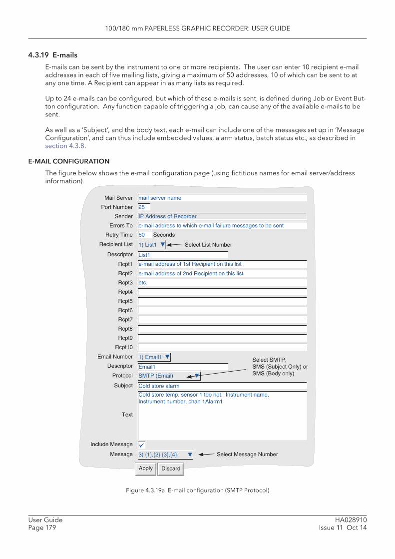
100/180 mm PAPERLESS GRAPHIC RECORDER: USER GUIDE
HA028910Issue 11 Oct 14
User GuidePage 179
4.3.19 E-mails
E-mails can be sent by the instrument to one or more recipients. The user can enter 10 recipient e-mail addresses in each of fi ve mailing lists, giving a maximum of 50 addresses, 10 of which can be sent to at any one time. A Recipient can appear in as many lists as required.
Up to 24 e-mails can be confi gured, but which of these e-mails is sent, is defi ned during Job or Event But-ton confi guration. Any function capable of triggering a job, can cause any of the available e-mails to be sent.
As well as a ‘Subject’, and the body text, each e-mail can include one of the messages set up in ‘Message Confi guration’, and can thus include embedded values, alarm status, batch status etc., as described in section 4.3.8.
E-MAIL CONFIGURATION
The fi gure below shows the e-mail confi guration page (using fi ctitious names for email server/address information).
Figure 4.3.19a E-mail confi guration (SMTP Protocol)
Mail Server
Port Number
Sender
Errors To
Retry Time
Recipient List
Descriptor
Rcpt1
Rcpt2
Rcpt3
Rcpt4
Rcpt5
Rcpt6
Rcpt7
Rcpt8
Rcpt9
Rcpt10
Email Number
Descriptor
Protocol
Subject
Text
Include Message
Message
Seconds
Select List Number
Select SMTP,SMS (Subject Only) orSMS (Body only)
Select Message Number
Apply Discard
mail server name
25
IP Address of Recorder
e-mail address to which e-mail failure messages to be sent
60
1) List1
List1
e-mail address of 1st Recipient on this list
e-mail address of 2nd Recipient on this list
Cold store alarm
Cold store temp. sensor 1 too hot. Instrument name,Instrument number, chan 1Alarm1
SMTP (Email)
etc.
3) {1},{2},{3},{4}
Email1
1) Email1
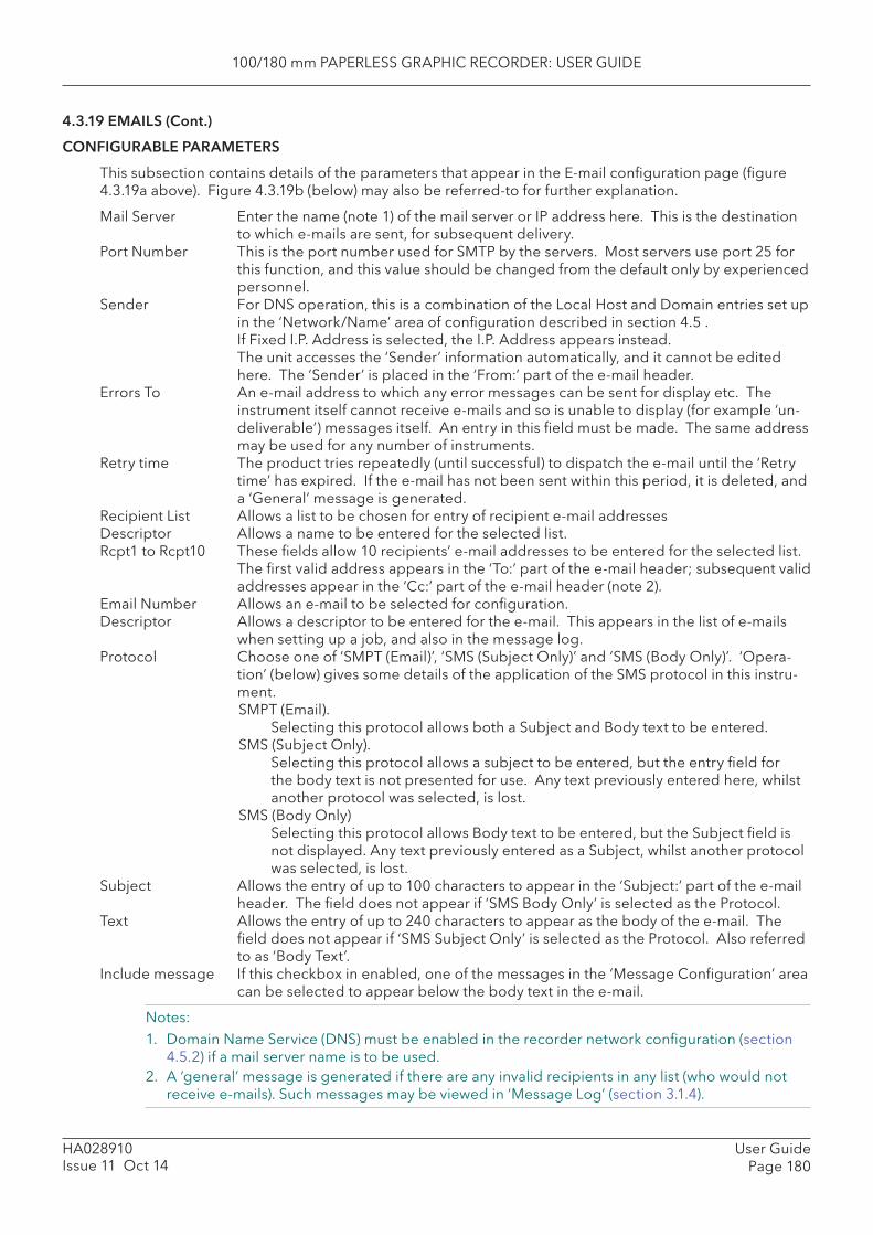
100/180 mm PAPERLESS GRAPHIC RECORDER: USER GUIDE
User GuidePage 180
HA028910Issue 11 Oct 14
4.3.19 EMAILS (Cont.)
CONFIGURABLE PARAMETERS
This subsection contains details of the parameters that appear in the E-mail confi guration page (fi gure 4.3.19a above). Figure 4.3.19b (below) may also be referred-to for further explanation.
Mail Server Enter the name (note 1) of the mail server or IP address here. This is the destination to which e-mails are sent, for subsequent delivery.
Port Number This is the port number used for SMTP by the servers. Most servers use port 25 for this function, and this value should be changed from the default only by experienced personnel.
Sender For DNS operation, this is a combination of the Local Host and Domain entries set up in the ‘Network/Name’ area of confi guration described in section 4.5 .
If Fixed I.P. Address is selected, the I.P. Address appears instead. The unit accesses the ‘Sender’ information automatically, and it cannot be edited
here. The ‘Sender’ is placed in the ‘From:’ part of the e-mail header. Errors To An e-mail address to which any error messages can be sent for display etc. The
instrument itself cannot receive e-mails and so is unable to display (for example ‘un-deliverable’) messages itself. An entry in this fi eld must be made. The same address may be used for any number of instruments.
Retry time The product tries repeatedly (until successful) to dispatch the e-mail until the ‘Retry time’ has expired. If the e-mail has not been sent within this period, it is deleted, and a ‘General’ message is generated.
Recipient List Allows a list to be chosen for entry of recipient e-mail addresses Descriptor Allows a name to be entered for the selected list. Rcpt1 to Rcpt10 These fi elds allow 10 recipients’ e-mail addresses to be entered for the selected list.
The fi rst valid address appears in the ‘To:’ part of the e-mail header; subsequent valid addresses appear in the ‘Cc:’ part of the e-mail header (note 2).
Email Number Allows an e-mail to be selected for confi guration. Descriptor Allows a descriptor to be entered for the e-mail. This appears in the list of e-mails
when setting up a job, and also in the message log. Protocol Choose one of ‘SMPT (Email)’, ‘SMS (Subject Only)’ and ‘SMS (Body Only)’. ‘Opera-
tion’ (below) gives some details of the application of the SMS protocol in this instru-ment. SMPT (Email).
Selecting this protocol allows both a Subject and Body text to be entered. SMS (Subject Only).
Selecting this protocol allows a subject to be entered, but the entry fi eld for the body text is not presented for use. Any text previously entered here, whilst another protocol was selected, is lost.
SMS (Body Only)Selecting this protocol allows Body text to be entered, but the Subject fi eld is not displayed. Any text previously entered as a Subject, whilst another protocol was selected, is lost.
Subject Allows the entry of up to 100 characters to appear in the ‘Subject:’ part of the e-mail header. The fi eld does not appear if ‘SMS Body Only’ is selected as the Protocol.
Text Allows the entry of up to 240 characters to appear as the body of the e-mail. The fi eld does not appear if ‘SMS Subject Only’ is selected as the Protocol. Also referred to as ‘Body Text’.
Include message If this checkbox in enabled, one of the messages in the ‘Message Confi guration’ area can be selected to appear below the body text in the e-mail.
Notes:1. Domain Name Service (DNS) must be enabled in the recorder network confi guration (section
4.5.2) if a mail server name is to be used. 2. A ‘general’ message is generated if there are any invalid recipients in any list (who would not
receive e-mails). Such messages may be viewed in ‘Message Log’ (section 3.1.4).
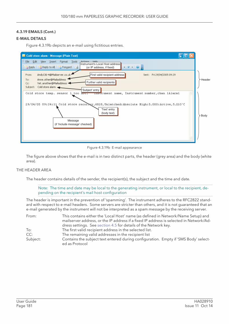
100/180 mm PAPERLESS GRAPHIC RECORDER: USER GUIDE
HA028910Issue 11 Oct 14
User GuidePage 181
4.3.19 EMAILS (Cont.)
E-MAIL DETAILS
Figure 4.3.19b depicts an e-mail using fi ctitious entries.
Figure 4.3.19b E-mail appearance
The fi gure above shows that the e-mail is in two distinct parts, the header (grey area) and the body (white area).
THE HEADER AREA
The header contains details of the sender, the recipient(s), the subject and the time and date.
Note: The time and date may be local to the generating instrument, or local to the recipient, de-pending on the recipient’s mail host confi guration
The header is important in the prevention of ‘spamming’. The instrument adheres to the RFC2822 stand-ard with respect to e-mail headers. Some servers are stricter than others, and it is not guaranteed that an e-mail generated by the instrument will not be interpreted as a spam message by the receiving server.
From: This contains either the ‘Local Host’ name (as defi ned in Network/Name Setup) and mailserver address, or the IP address if a fi xed IP address is selected in Network/Ad-dress settings. See section 4.5 for details of the Network key.
To: The fi rst valid recipient address in the selected list.CC: The remaining valid addresses in the recipient listSubject: Contains the subject text entered during confi guration. Empty if ‘SMS Body’ select-
ed as Protocol
Message(if 'Include message' checked)
'Text' entry(body text)
First valid recipient address
Further valid recipientsHeader
Body
Instrument's Local Host address(or IP address, if fixed)
'Subject' entry

100/180 mm PAPERLESS GRAPHIC RECORDER: USER GUIDE
User GuidePage 182
HA028910Issue 11 Oct 14
4.3.19 EMAILS (Cont.)
THE BODY AREA
This contains the body text, along with any appended messages. In the example above the message has the embedded values of Instrument name, Instrument number, channel 1 alarm 1 status, as implied by the body text.
OPERATION1. E-mails are generated either by job or by operation of an Event Button from a User screen (if the
Screen builder option is fi tted).2. Every time the sending of an e-mail is requested, a ‘General’ note is generated and appears in the
message log for all groups. The format is: Date, Time Sent <e-mail descriptor> to List N, where <e-mail descriptor> represents the descriptor entered in the confi guration page for the e-mail, and ‘List N’ is the recipient list to whom the e-mail was sent.
3. Access to e-mails is restricted to users with ‘Full Confi guration’ permission.4. Signing/Authorizing restrictions can be applied only to e-mails generated by Event button opera-
tion, as part of the Event button’s confi guration (section 4.3.7).5. The instrument implements the Simple Message Transfer Protocol (SMTP), incorporating Multipur-
pose Internet Mail extensions.6. The instrument does not implement the Short Message Service (SMS) protocol, though it is able
to send SMS messages to a mobile phone via an appropriate server or gateway. As some servers/gateways use the ‘subject’ as the SMS message, and others use the body text, these alternatives are provided for in the Protocol pick list in the Confi guration page described above.
7. A new event source ‘Email fail’ can be used to trigger a job list should an e-mail send failure occur.
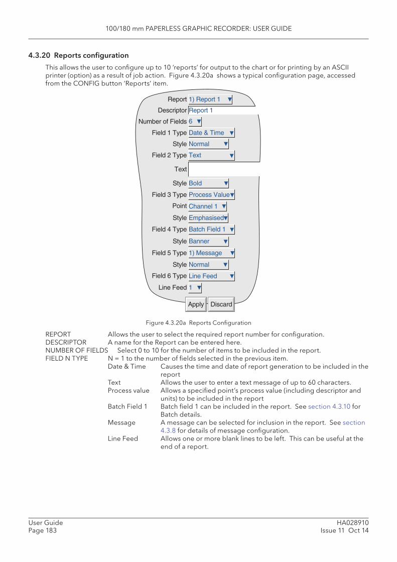
100/180 mm PAPERLESS GRAPHIC RECORDER: USER GUIDE
HA028910Issue 11 Oct 14
User GuidePage 183
4.3.20 Reports confi guration
This allows the user to confi gure up to 10 ‘reports’ for output to the chart or for printing by an ASCII printer (option) as a result of job action. Figure 4.3.20a shows a typical confi guration page, accessed from the CONFIG button ‘Reports’ item.
Figure 4.3.20a Reports Confi guration
REPORT Allows the user to select the required report number for confi guration. DESCRIPTOR A name for the Report can be entered here. NUMBER OF FIELDS Select 0 to 10 for the number of items to be included in the report. FIELD N TYPE N = 1 to the number of fi elds selected in the previous item.
Date & Time Causes the time and date of report generation to be included in the report
Text Allows the user to enter a text message of up to 60 characters. Process value Allows a specifi ed point’s process value (including descriptor and
units) to be included in the report Batch Field 1 Batch fi eld 1 can be included in the report. See section 4.3.10 for
Batch details. Message A message can be selected for inclusion in the report. See section
4.3.8 for details of message confi guration. Line Feed Allows one or more blank lines to be left. This can be useful at the
end of a report.
Number of Fields
Report
Descriptor
Field 1 Type
Style
Field 2 Type
Text
Style
Field 3 Type
Point
Style
Field 4 Type
Style
Field 5 Type
Style
Field 6 Type
Line Feed
Apply Discard
Bold
Process Value
Channel 1
Emphasised
Batch Field 1
1) Message
Normal
Line Feed
1
1) Report 1
Date & Time
Normal
Text
Report 1
6
Banner
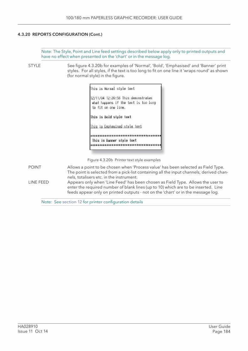
100/180 mm PAPERLESS GRAPHIC RECORDER: USER GUIDE
User GuidePage 184
HA028910Issue 11 Oct 14
4.3.20 REPORTS CONFIGURATION (Cont.)
Note: The Style, Point and Line feed settings described below apply only to printed outputs and have no effect when presented on the ‘chart’ or in the message log.
STYLE See fi gure 4.3.20b for examples of ‘ Normal’, ‘ Bold’, ‘ Emphasised’ and ‘ Banner’ print styles. For all styles, if the text is too long to fi t on one line it ‘wraps round’ as shown (for normal style) in the fi gure.
Figure 4.3.20b Printer text style examples
POINT Allows a point to be chosen when ‘Process value’ has been selected as Field Type. The point is selected from a pick-list containing all the input channels, derived chan-nels, totalisers etc. in the instrument.
LINE FEED Appears only when ‘Line Feed’ has been chosen as Field Type. Allows the user to enter the required number of blank lines (up to 10) which are to be inserted. Line feeds appear only on printed outputs - not on the ‘chart’ or in the message log.
Note: See section 12 for printer confi guration details

100/180 mm PAPERLESS GRAPHIC RECORDER: USER GUIDE
HA028910Issue 11 Oct 14
User GuidePage 185
4.3.21 Ethernet/IP™ Option
Note: Full details of Ethernet/IP protocol are available from the ODVA web site http://www.odva.org
EtherNet/IP (Ethernet/Industrial Protocol) is a ‘producer-consumer’ communication system used to allow industrial devices to exchange time-critical control data. Such devices range from simple I/O devices such as sensors/actuators, to complex control devices such as robots and PLCs. The producer-consumer model allows the exchange of information between a single sending device (producer) and a large number of receiving devices (consumers) without having to send data multiple times to multiple destina-tions.
EtherNet/IP makes use of the CIP (Control & Information Protocol), common network, transport and application layers currently implemented by DeviceNet and ControlNet. Standard Ethernet and TCP/IP technology is used to transport CIP communications packets. The result is a common, open application layer on top of Ethernet and TCP/IP protocols.
In order to record and trend data that has been written by the client, the relevant channel or maths channel must be confi gured with ‘Input Type’ set to ‘Ethernet/IP Comms Input’ and the channel must be included in a Recording-enabled group. See sections, 4.3.2 (Group confi guration), 4.3.3 (Channel con-fi guration) and 4.3.11 (maths confi guration) as necessary.
MESSAGING
Ethernet/IP uses two forms of messaging:
UNCONNECTED MESSAGINGThis is used in the connection establishment process and for infrequent, low-priority messages. The unconnected resources in a device are called the ‘ Unconnected Message Manager’ ( UCMM).
CONNECTED MESSAGINGThis uses resources within each node that are dedicated, in advance, to a particular purpose, such as fre-quent explicit message transactions or real-time I/O data transfers. Connection resources are reserved and confi gured using communications services available via the UCMM.
The process of opening a connection is called ‘Connection Origination’. The node that initiates the con-nection establishment request is called the ‘Connection Originator’ (or ‘Originator’) and the node that responds to the establishment request is called a ‘Connection Target’ (or ‘Target’). Ethernet/IP has two types of messaging connections:
EXPLICIT MESSAGING CONNECTIONSThese are point-to-point relationships that are established to facilitate request-response transaction between two nodes. These connections are general purpose in nature and can be used to reach any network-accessible items within a device. Explicit messaging connections use TCP/IP services to move messages across Ethernet.
IMPLICIT (I/O DATA) CONNECTIONSThese are established to move application-specifi c I/O data at regular intervals. These connections are typically set up as one-to-many relationships in order to take full advantage of the producer-consumer multicast model. Implicit messaging uses UDP/IP resources to establish multicast data.
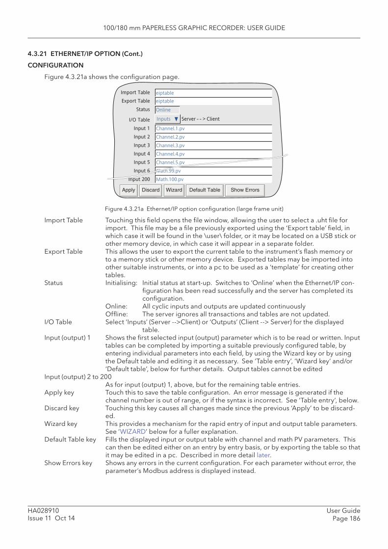
100/180 mm PAPERLESS GRAPHIC RECORDER: USER GUIDE
User GuidePage 186
HA028910Issue 11 Oct 14
4.3.21 ETHERNET/IP OPTION (Cont.)
CONFIGURATION
Figure 4.3.21a shows the confi guration page.
Figure 4.3.21a Ethernet/IP option confi guration (large frame unit)
Import Table Touching this fi eld opens the fi le window, allowing the user to select a .uht fi le for import. This fi le may be a fi le previously exported using the ‘Export table’ fi eld, in which case it will be found in the \user\ folder, or it may be located on a USB stick or other memory device, in which case it will appear in a separate folder.
Export Table This allows the user to export the current table to the instrument’s fl ash memory or to a memory stick or other memory device. Exported tables may be imported into other suitable instruments, or into a pc to be used as a ‘template’ for creating other tables.
Status Initialising: Initial status at start-up. Switches to ‘Online’ when the Ethernet/IP con-fi guration has been read successfully and the server has completed its confi guration.
Online: All cyclic inputs and outputs are updated continuously Offl ine: The server ignores all transactions and tables are not updated. I/O Table Select ‘Inputs’ (Server -->Client) or ‘Outputs’ (Client --> Server) for the displayed
table. Input ( output) 1 Shows the fi rst selected input (output) parameter which is to be read or written. Input
tables can be completed by importing a suitable previously confi gured table, by entering individual parameters into each fi eld, by using the Wizard key or by using the Default table and editing it as necessary. See ‘Table entry’, ‘Wizard key’ and/or ‘Default table’, below for further details. Output tables cannot be edited
Input (output) 2 to 200As for input (output) 1, above, but for the remaining table entries.
Apply key Touch this to save the table confi guration. An error message is generated if the channel number is out of range, or if the syntax is incorrect. See ‘Table entry’, below.
Discard key Touching this key causes all changes made since the previous ‘Apply’ to be discard-ed.
Wizard key This provides a mechanism for the rapid entry of input and output table parameters. See ‘WIZARD’ below for a fuller explanation.
Default Table key Fills the displayed input or output table with channel and math PV parameters. This can then be edited either on an entry by entry basis, or by exporting the table so that it may be edited in a pc. Described in more detail later.
Show Errors key Shows any errors in the current confi guration. For each parameter without error, the parameter’s Modbus address is displayed instead.
Import Table
Export Table
Status
I/O Table
Input 1
Input 2
Input 3
Input 4
Input 5
Input 6
Input 200
eiptable
eiptable
Online
Inputs Server - - > Client
Channel.1.pv
Channel.2.pv
Channel.3.pv
Channel.4.pv
Channel.5.pv
Ch
Apply Discard Wizard Default Table Show Errors
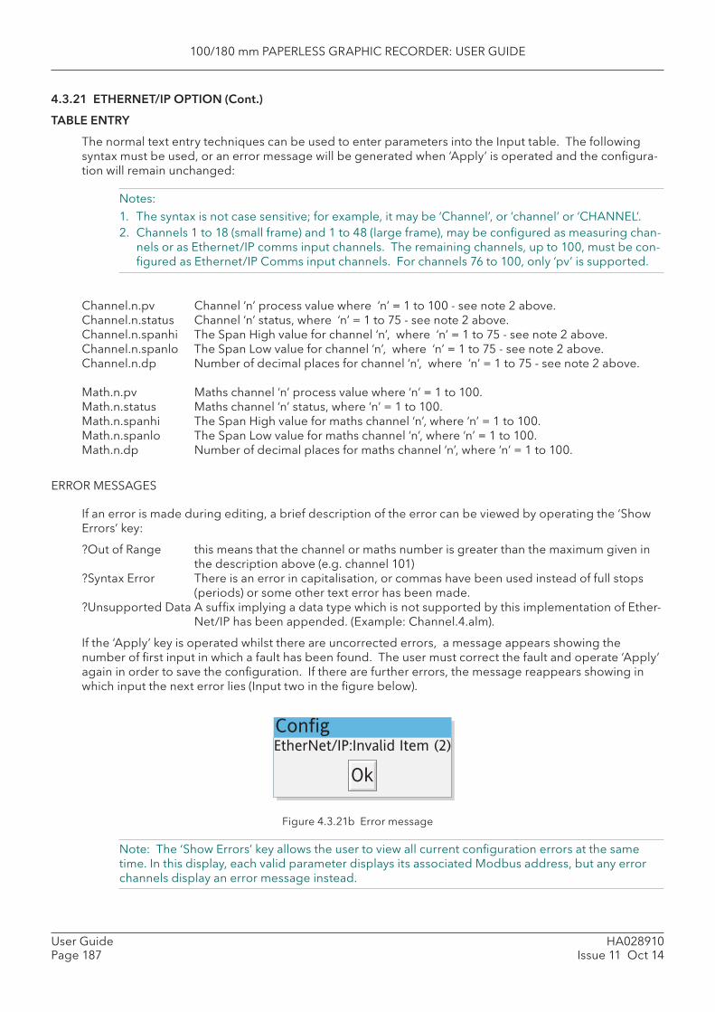
100/180 mm PAPERLESS GRAPHIC RECORDER: USER GUIDE
HA028910Issue 11 Oct 14
User GuidePage 187
4.3.21 ETHERNET/IP OPTION (Cont.)
TABLE ENTRY
The normal text entry techniques can be used to enter parameters into the Input table. The following syntax must be used, or an error message will be generated when ‘Apply’ is operated and the confi gura-tion will remain unchanged:
Notes: 1. The syntax is not case sensitive; for example, it may be ‘Channel’, or ‘channel’ or ‘CHANNEL’.2. Channels 1 to 18 (small frame) and 1 to 48 (large frame), may be confi gured as measuring chan-
nels or as Ethernet/IP comms input channels. The remaining channels, up to 100, must be con-fi gured as Ethernet/IP Comms input channels. For channels 76 to 100, only ‘pv’ is supported.
Channel.n.pv Channel ‘n’ process value where ‘n’ = 1 to 100 - see note 2 above.Channel.n.status Channel ‘n’ status, where ‘n’ = 1 to 75 - see note 2 above.Channel.n.spanhi The Span High value for channel ‘n’, where ‘n’ = 1 to 75 - see note 2 above.Channel.n.spanlo The Span Low value for channel ‘n’, where ‘n’ = 1 to 75 - see note 2 above.Channel.n.dp Number of decimal places for channel ‘n’, where ‘n’ = 1 to 75 - see note 2 above.
Math.n.pv Maths channel ‘n’ process value where ‘n’ = 1 to 100.Math.n.status Maths channel ‘n’ status, where ‘n’ = 1 to 100.Math.n.spanhi The Span High value for maths channel ‘n’, where ‘n’ = 1 to 100.Math.n.spanlo The Span Low value for maths channel ‘n’, where ‘n’ = 1 to 100.Math.n.dp Number of decimal places for maths channel ‘n’, where ‘n’ = 1 to 100.
ERROR MESSAGES
If an error is made during editing, a brief description of the error can be viewed by operating the ‘Show Errors’ key:
?Out of Range this means that the channel or maths number is greater than the maximum given in the description above (e.g. channel 101)
?Syntax Error There is an error in capitalisation, or commas have been used instead of full stops (periods) or some other text error has been made.
?Unsupported Data A suffi x implying a data type which is not supported by this implementation of Ether-Net/IP has been appended. (Example: Channel.4.alm).
If the ‘Apply’ key is operated whilst there are uncorrected errors, a message appears showing the number of fi rst input in which a fault has been found. The user must correct the fault and operate ‘Apply’ again in order to save the confi guration. If there are further errors, the message reappears showing in which input the next error lies (Input two in the fi gure below).
Figure 4.3.21b Error message
Note: The ‘Show Errors’ key allows the user to view all current confi guration errors at the same time. In this display, each valid parameter displays its associated Modbus address, but any error channels display an error message instead.
ConfigEtherNet/IP:Invalid Item (2)
Ok
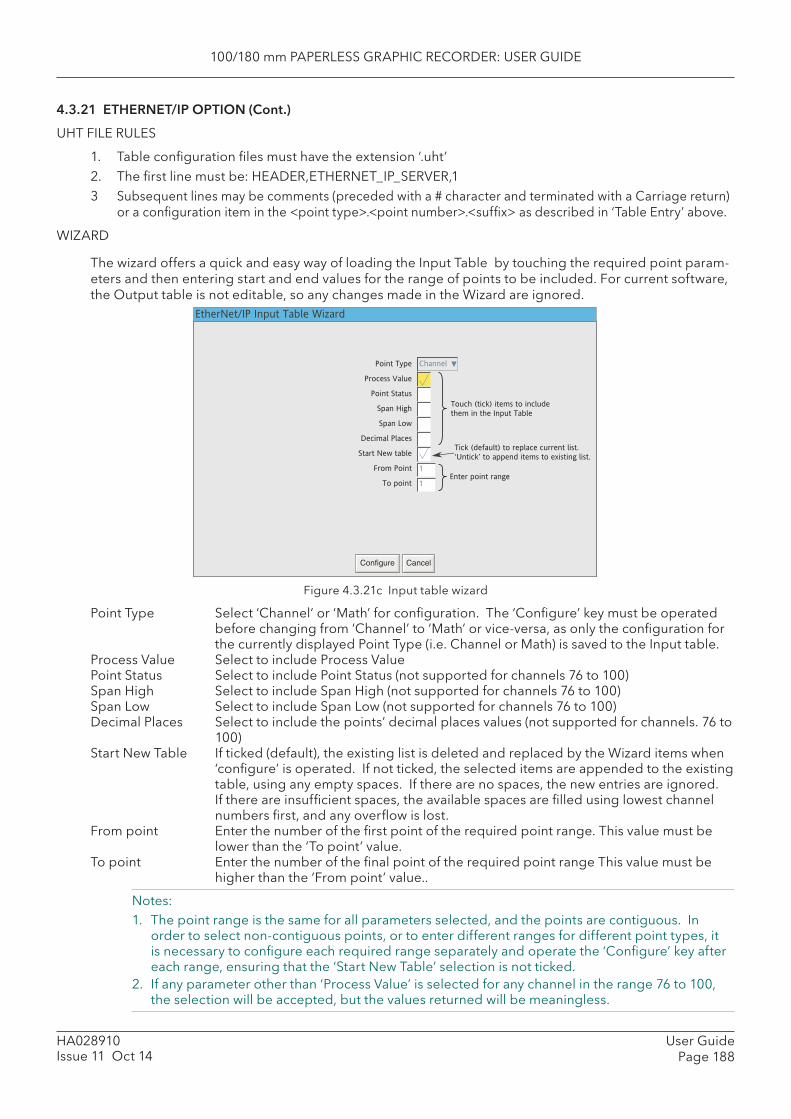
100/180 mm PAPERLESS GRAPHIC RECORDER: USER GUIDE
User GuidePage 188
HA028910Issue 11 Oct 14
4.3.21 ETHERNET/IP OPTION (Cont.)
UHT FILE RULES
1. Table confi guration fi les must have the extension ‘.uht’ 2. The fi rst line must be: HEADER,ETHERNET_IP_SERVER,13 Subsequent lines may be comments (preceded with a # character and terminated with a Carriage return)
or a confi guration item in the <point type>.<point number>.<suffi x> as described in ‘Table Entry’ above.
WIZARD
The wizard offers a quick and easy way of loading the Input Table by touching the required point param-eters and then entering start and end values for the range of points to be included. For current software, the Output table is not editable, so any changes made in the Wizard are ignored.
Figure 4.3.21c Input table wizard
Point Type Select ‘Channel’ or ‘Math’ for confi guration. The ‘Confi gure’ key must be operated before changing from ‘Channel’ to ‘Math’ or vice-versa, as only the confi guration for the currently displayed Point Type (i.e. Channel or Math) is saved to the Input table.
Process Value Select to include Process Value Point Status Select to include Point Status (not supported for channels 76 to 100) Span High Select to include Span High (not supported for channels 76 to 100)Span Low Select to include Span Low (not supported for channels 76 to 100) Decimal Places Select to include the points’ decimal places values (not supported for channels. 76 to
100) Start New Table If ticked (default), the existing list is deleted and replaced by the Wizard items when
‘confi gure’ is operated. If not ticked, the selected items are appended to the existing table, using any empty spaces. If there are no spaces, the new entries are ignored. If there are insuffi cient spaces, the available spaces are fi lled using lowest channel numbers fi rst, and any overfl ow is lost.
From point Enter the number of the fi rst point of the required point range. This value must be lower than the ‘To point’ value.
To point Enter the number of the fi nal point of the required point range This value must be higher than the ‘From point’ value..
Notes: 1. The point range is the same for all parameters selected, and the points are contiguous. In
order to select non-contiguous points, or to enter different ranges for different point types, it is necessary to confi gure each required range separately and operate the ‘Confi gure’ key after each range, ensuring that the ‘Start New Table’ selection is not ticked.
2. If any parameter other than ‘Process Value’ is selected for any channel in the range 76 to 100, the selection will be accepted, but the values returned will be meaningless.
Point Type
Process Value
Point Status
Span High
Span Low
Decimal Places
Start New table
From Point
To point
Configure Cancel
Channel
1
1
EtherNet/IP Input Table Wizard
Touch (tick) items to include
them in the Input Table
Enter point range
Tick (default) to replace current list.
to append items to existing list.

100/180 mm PAPERLESS GRAPHIC RECORDER: USER GUIDE
HA028910Issue 11 Oct 14
User GuidePage 189
4.3.21 ETHERNET/IP OPTION (Cont.)
DEFAULT TABLE KEY
Clicking on this key causes the relevant table to be populated with a default set of parameters.
For input tables, these parameters are: Channel.1.pv to Channel.100.pv followed by Math.1.pv to Math.100.pv.
The output table parameters are: Channel.1.pv to Channel.100.pv followed by Math.1.pv to Math.100.pv.
SHOW ERRORS KEY
Clicking on this key causes the parameter addresses to appear after the parameter names in the input and output tables. If a syntax or other error has been made in loading the input table, a description of the error type appears in this view (see ‘ERROR MESSAGES’, above).
OUTPUT TABLE PARAMETER MODBUS ADDRESSES
In all cases, the addresses for the output parameters can be viewed by operating the ‘Show errors’ key. The ad-dresses for channels 1 to 75 and maths 1 to 100 can be found as described in Section 8.4.3 (Channel Runtime data), and section 4.3.11 (Maths channel Run-time data). Addresses for channels 76 to 100, are given below:
Channel.76.pv Channel 76 process value Scaled Read only FCBF (64703) 1Channel.77.pv Channel 77 process value Scaled Read only FCC2 (64706) 1Channel.78.pv Channel 78 process value Scaled Read only FCC5 (64709) 1Channel.79.pv Channel 79 process value Scaled Read only FCC8 (64712) 1Channel.80.pv Channel 80 process value Scaled Read only FCCB (64715) 1Channel.81.pv Channel 81 process value Scaled Read only FCCE (64718) 1Channel.82.pv Channel 82 process value Scaled Read only FCD1 (64721) 1Channel.83.pv Channel 63 process value Scaled Read only FCD4 (64724) 1Channel.84.pv Channel 64 process value Scaled Read only FCD7 (64727) 1Channel.85.pv Channel 65 process value Scaled Read only FCDA (64730) 1Channel.86.pv Channel 66 process value Scaled Read only FCDD (64733) 1Channel.87.pv Channel 67 process value Scaled Read only FCE0 (64736) 1Channel.88.pv Channel 68 process value Scaled Read only FCE3 (64739) 1Channel.89.pv Channel 69 process value Scaled Read only FCE6 (64742) 1Channel.90.pv Channel 70 process value Scaled Read only FCE9 (64745) 1Channel.91.pv Channel 71 process value Scaled Read only FCEC (64748) 1Channel.92.pv Channel 72 process value Scaled Read only FCEF (64751) 1Channel.93.pv Channel 73 process value Scaled Read only FCF2 (64754) 1Channel.94.pv Channel 74 process value Scaled Read only FCF5 (64757) 1Channel.95.pv Channel 75 process value Scaled Read only FCF8 (64760) 1Channel.96.pv Channel 76 process value Scaled Read only FCFB (64763) 1Channel.97.pv Channel 77 process value Scaled Read only FCFE (64766) 1Channel.98.pv Channel 78 process value Scaled Read only FD01 (64769) 1Channel.99.pv Channel 79 process value Scaled Read only FD04 (64772) 1Channel.100.pv Channel 80 process value Scaled Read only FD07 (64775) 1
Parameter Description Type Access Start Addr. RegisterName Hex (Dec) Length
Table 4.3.21 Parameter addresses for channels 76 to 100
CONFIGURING A PLC
The following instructions describe how to confi gure a PLC to communicate with a Paperless graphic recorder. Although a specifi c PLC was used in generating these instructions, the detail should be general enough to allow any other PLC to be used.
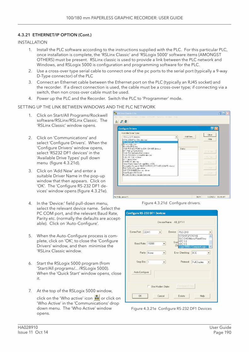
100/180 mm PAPERLESS GRAPHIC RECORDER: USER GUIDE
User GuidePage 190
HA028910Issue 11 Oct 14
4.3.21 ETHERNET/IP OPTION (Cont.)
INSTALLATION
1. Install the PLC software according to the instructions supplied with the PLC. For this particular PLC, once installation is complete, the ‘RSLinx Classic’ and ‘RSLogix 5000’ software items (AMONGST OTHERS) must be present. RSLinx classic is used to provide a link between the PLC network and Windows, and RSLogix 5000 is confi guration and programming software for the PLC.
2. Use a cross-over type serial cable to connect one of the pc ports to the serial port (typically a 9-way D-Type connector) of the PLC
3. Connect an Ethernet cable between the Ethernet port on the PLC (typically an RJ45 socket) and the recorder. If a direct connection is used, the cable must be a cross-over type; if connecting via a switch, then non cross-over cable must be used.
4. Power up the PLC and the Recorder. Switch the PLC to ‘Programmer’ mode.
SETTING UP THE LINK BETWEEN WINDOWS AND THE PLC NETWORK
Figure 4.3.21d Confi gure drivers.
1. Click on Start/All Programs/Rockwell software/RSLinx/RSLinx Classic. The ‘RSLinx Classic’ window opens.
2. Click on ‘Communications’ and select ‘Confi gure Drivers’. When the ‘Confi gure Drivers’ window opens, select ‘RS232 DF1 devices’ in the ‘Available Drive Types’ pull down menu (fi gure 4.3.21d).
3. Click on ‘Add New’ and enter a suitable Driver Name in the pop-up window that then appears. Click on ‘OK’. The ‘Confi gure RS-232 DF1 de-vices’ window opens (fi gure 4.3.21e).
4. In the ‘Device:’ fi eld pull-down menu, select the relevant device name. Select the PC COM port, and the relevant Baud Rate, Parity etc. (normally the defaults are accept-able). Click on ‘Auto-Confi gure’.
5. When the Auto-Confi gure process is com-plete, click on ‘OK’, to close the ‘Confi gure Drivers’ window, and then minimise the ‘RSLinx Classic window.
6. Start the RSLogix 5000 program (from ‘Start/All programs/... /RSLogix 5000). When the ‘Quick Start’ window opens, close it.
7. At the top of the RSLogix 5000 window,
click on the ‘Who active’ icon or click on ‘Who Active’ in the ‘Communications’ drop down menu. The ‘Who Active’ window opens.
Figure 4.3.21e Confi gure RS-232 DF1 Devices
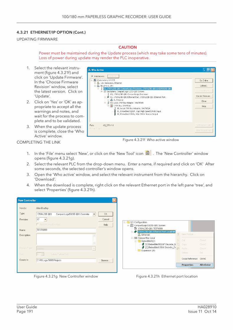
100/180 mm PAPERLESS GRAPHIC RECORDER: USER GUIDE
HA028910Issue 11 Oct 14
User GuidePage 191
4.3.21 ETHERNET/IP OPTION (Cont.)
UPDATING FIRMWARE
CAUTIONPower must be maintained during the Update process (which may take some tens of minutes). Loss of power during update may render the PLC inoperative.
1. Select the relevant instru-ment (fi gure 4.3.21f) and click on ‘Update Firmware’. In the ‘Choose Firmware Revision’ window, select the latest version. Click on ‘Update’.
2. Click on ‘Yes’ or ‘OK’ as ap-propriate to accept all the warnings and notes, and wait for the process to com-plete and to be validated.
3. When the update process is complete, close the ‘Who Active’ window.
Figure 4.3.21f Who active windowCOMPLETING THE LINK
1. In the ‘File’ menu select ‘New’, or click on the ‘New Tool’ icon . The ‘New Controller’ window opens (fi gure 4.3.21g).
2. Select the relevant PLC from the drop-down menu. Enter a name, if required and click on ‘OK’ After some seconds, the selected controller’s window opens.
3. Open the ‘Who active’ window, and select the relevant instrument from the hierarchy. Click on ‘Download’.
4. When the download is complete, right click on the relevant Ethernet port in the left pane ‘tree’, and select ‘Properties’ (fi gure 4.3.21h).
Figure 4.3.21g New Controller window Figure 4.3.21h Ethernet port location
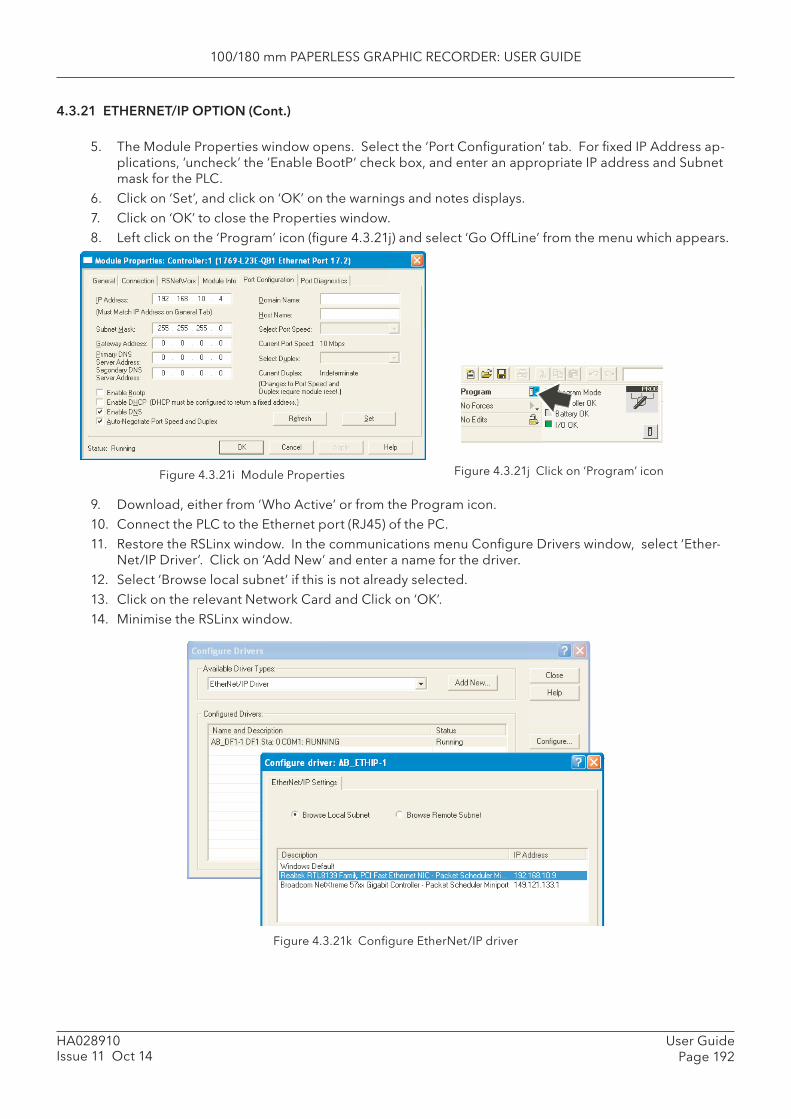
100/180 mm PAPERLESS GRAPHIC RECORDER: USER GUIDE
User GuidePage 192
HA028910Issue 11 Oct 14
4.3.21 ETHERNET/IP OPTION (Cont.)
5. The Module Properties window opens. Select the ‘Port Confi guration’ tab. For fi xed IP Address ap-plications, ‘uncheck’ the ‘Enable BootP’ check box, and enter an appropriate IP address and Subnet mask for the PLC.
6. Click on ‘Set’, and click on ‘OK’ on the warnings and notes displays.7. Click on ‘OK’ to close the Properties window.8. Left click on the ‘Program’ icon (fi gure 4.3.21j) and select ‘Go OffLine’ from the menu which appears.
Figure 4.3.21i Module Properties Figure 4.3.21j Click on ‘Program’ icon
9. Download, either from ‘Who Active’ or from the Program icon.10. Connect the PLC to the Ethernet port (RJ45) of the PC.11. Restore the RSLinx window. In the communications menu Confi gure Drivers window, select ‘Ether-
Net/IP Driver’. Click on ‘Add New’ and enter a name for the driver.12. Select ‘Browse local subnet’ if this is not already selected.13. Click on the relevant Network Card and Click on ‘OK’.14. Minimise the RSLinx window.
Figure 4.3.21k Confi gure EtherNet/IP driver
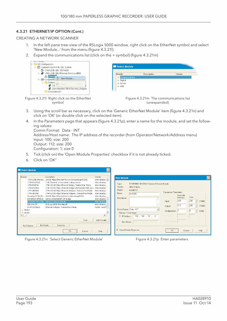
100/180 mm PAPERLESS GRAPHIC RECORDER: USER GUIDE
HA028910Issue 11 Oct 14
User GuidePage 193
4.3.21 ETHERNET/IP OPTION (Cont.)
CREATING A NETWORK SCANNER
1. In the left pane tree-view of the RSLogix 5000 window, right click on the EtherNet symbol and select ‘New Module...’ from the menu (fi gure 4.3.21l).
2. Expand the communications list (click on the + symbol) (fi gure 4.3.21m)
Figure 4.3.21l Right click on the EtherNet symbol
Figure 4.3.21m The communications list (unexpanded)
Figure 4.3.21n ‘Select Generic EtherNet Module’ Figure 4.3.21p Enter parameters
3. Using the scroll bar as necessary, click on the ‘Generic EtherNet Module’ item (fi gure 4.3.21n) and click on ‘OK’ (or double click on the selected item).
4. In the Parameters page that appears (fi gure 4.3.21p), enter a name for the module, and set the follow-ing values:Comm Format: Data - INTAddress/Host name: The IP address of the recorder (from Operator/Network/Address menu)Input: 100; size: 200Output: 112; size: 200Confi guration: 1; size 0
5. Tick (click on) the ‘Open Module Properties’ checkbox if it is not already ticked.6. Click on ‘OK”
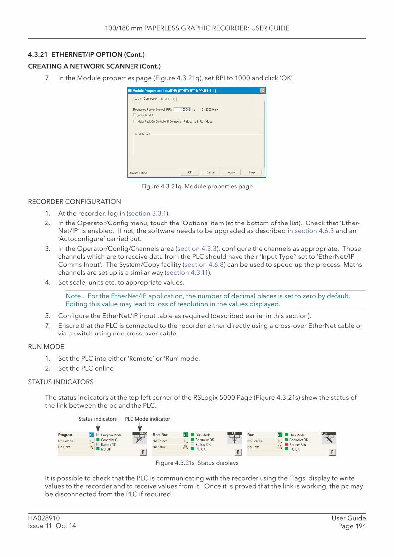
100/180 mm PAPERLESS GRAPHIC RECORDER: USER GUIDE
User GuidePage 194
HA028910Issue 11 Oct 14
4.3.21 ETHERNET/IP OPTION (Cont.)
CREATING A NETWORK SCANNER (Cont.)
7. In the Module properties page (Figure 4.3.21q), set RPI to 1000 and click ‘OK’.
Figure 4.3.21q Module properties page
RECORDER CONFIGURATION
1. At the recorder. log in (section 3.3.1).2. In the Operator/Confi g menu, touch the ‘Options’ item (at the bottom of the list). Check that ‘Ether-
Net/IP’ is enabled. If not, the software needs to be upgraded as described in section 4.6.3 and an ‘Autoconfi gure’ carried out.
3. In the Operator/Confi g/Channels area (section 4.3.3), confi gure the channels as appropriate. Those channels which are to receive data from the PLC should have their ‘Input Type’’ set to ‘EtherNet/IP Comms Input’. The System/Copy facility (section 4.6.8) can be used to speed up the process. Maths channels are set up is a similar way (section 4.3.11).
4. Set scale, units etc. to appropriate values.
Note... For the EtherNet/IP application, the number of decimal places is set to zero by default. Editing this value may lead to loss of resolution in the values displayed.
5. Confi gure the EtherNet/IP input table as required (described earlier in this section).7. Ensure that the PLC is connected to the recorder either directly using a cross-over EtherNet cable or
via a switch using non cross-over cable.
RUN MODE
1. Set the PLC into either ‘Remote’ or ‘Run’ mode.2. Set the PLC online
STATUS INDICATORS
The status indicators at the top left corner of the RSLogix 5000 Page (Figure 4.3.21s) show the status of the link between the pc and the PLC.
Figure 4.3.21s Status displays
It is possible to check that the PLC is communicating with the recorder using the ‘Tags’ display to write values to the recorder and to receive values from it. Once it is proved that the link is working, the pc may be disconnected from the PLC if required.
PLC Mode indicatorStatus indicators
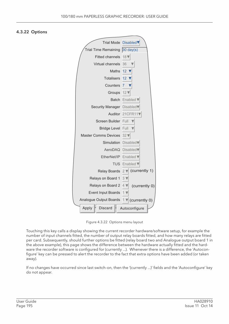
100/180 mm PAPERLESS GRAPHIC RECORDER: USER GUIDE
HA028910Issue 11 Oct 14
User GuidePage 195
4.3.22 Options
Figure 4.3.22 Options menu layout
Touching this key calls a display showing the current recorder hardware/software setup, for example the number of input channels fi tted, the number of output relay boards fi tted, and how many relays are fi tted per card. Subsequently, should further options be fi tted (relay board two and Analogue output board 1 in the above example), this page shows the difference between the hardware actually fi tted and the hard-ware the recorder software is confi gured for (currently ...). Whenever there is a difference, the ‘ Autocon-fi gure’ key can be pressed to alert the recorder to the fact that extra options have been added (or taken away).
If no changes have occurred since last switch-on, then the ‘( currently ...)’ fi elds and the ‘Autoconfi gure’ key do not appear.
�������� �� �����
�������������������� ������ ��
������������� ���
��������������� � �
���� �!�
����� �� �!�
"����� #�
$��% �!�
&���� '������
(��������������� �� �����
)���� !�"�����
(������&����� �����
&�����*�+�� �����
�� ����"�� ���+��� �!�
(�������� �� �����
)���), �� �����
'����-��./0 '������
�1( '������
������&�� !�
����� ���&���� ��
����� ���&���! 2�
'+����/�%���&�� ��
)�������3��%���&�� �
(currently 1)
(currently 0)
(currently 0)
Apply Discard Autoconfigure
100/180 mm PAPERLESS GRAPHIC RECORDER: USER GUIDE
User GuidePage 196
HA028910Issue 11 Oct 14
4.3.22 OPTIONS (Cont.)
TRIAL MODE
Enabling ‘Trial Mode’ allows the user to enable, temporarily, the various software options that are availa-ble. Once the user has made the required choices, the ‘Set Trial Options’ key at the bottom of the screen, must be operated, followed by an ‘Autoconfi gure’ procedure.
Initially, the trial mode is set to expire 30 days after enabling (whether the recorder is powered or not). Any change in confi guration results in a pop-up message stating how much of the 30 days period re-mains. Once Trial mode is disabled by the user, the remaining Trial Time Remaining’ value is retained until Trial Mode is re-enabled.
Notes:1. Trial mode enables/disables all options or features (except ‘Simulation’ and ‘History Mainte-
nance’) which are not fi tted or enabled in the recorder. The number and distribution of virtual channels reverts to that confi gured before Trial mode was invoked.
2. When disabling Trial mode, all confi guration for the trial features is lost. Should the user decide to purchase a trial feature, then it is recommended that the trial confi guration be saved (see section 4.2) so that it may be restored once the purchased trial feature is fi tted and enabled (keycodes cannot be entered in Trial Mode).
3. Trial mode can be enabled only by users with ‘Perform upgrades’ permission (section 4.4.1).
VIRTUAL CHANNELS
Virtual channels are Maths channels, Totalisers and Counters. The total number of virtual channels is as specifi ed at time of order. The user can select whatever combination of maths channels, totalisers and counters is required, so long as the total does not exceed the number of virtual channels available. If it does, a warning is given when the ‘Apply’ button is operated, and the edit is ignored.
Note: If more than 100 maths channels are confi gured, then the Modbus register addresses of totalisers and counters are affected. If for example there were 105 maths channels, then the value of totaliser 1 would be found at the address normally associated with totaliser 6, and the value of counter 1 would be found at the address normally associated with counter 6.

100/180 mm PAPERLESS GRAPHIC RECORDER: USER GUIDE
HA028910Issue 11 Oct 14
User GuidePage 197
4.3.22 OPTIONS (Cont.)
SIMULATION OPTION
This option consists of a number of additional jobs, as described below. This option is not enabled in ‘Trial mode’.
TREND FREEZE
When this ‘Trend’ category job (section 4.7.11) is initiated, the displays are held at their values at the time of initiation. When the recorder is ‘unfrozen’ the displays switch to their current values, and the clock re-starts from where it stopped. No blue line is drawn across the trace to indicate time discontinuity (Time change records - section 3.4).
Note: If ‘SNTP client enable’ is enabled (Network Address area - section 4.5), then the recorder time is synchronised at power-up only. I.E. the normal checks of recorder time compared with server time are not carried out with the Simulator option enabled.
If ‘SNTP server enable’ is enabled, then the recorder will supply recorder time.
CLEAR
This ‘Trend’ category job (section 4.7.11) clears the display. Used in conjunction with ‘Erase all History (below), this is known, in some applications, as Recall Mode.
ERASE ALL HISTORY
This ‘Recording’ category job (section 4.7.10) erases all the history fi les in the recorder. Used in conjunc-tion with ‘Clear’ (above), this is known, in some applications, as Recall Mode.
Note: If the 21CFR11 option is enabled, Erase All History jobs can be triggered, but are ignored, leaving the recording history unaffected.
SCREEN SAVER
This ‘Trend’ category job (section 4.7.11) switches the display brightness to the value set up in ‘Saver Display’ (Instrument Confi guration - section 4.3.1) for the duration of the job. The job overrides the ‘Save after’ time value also set up in Instrument Confi guration.
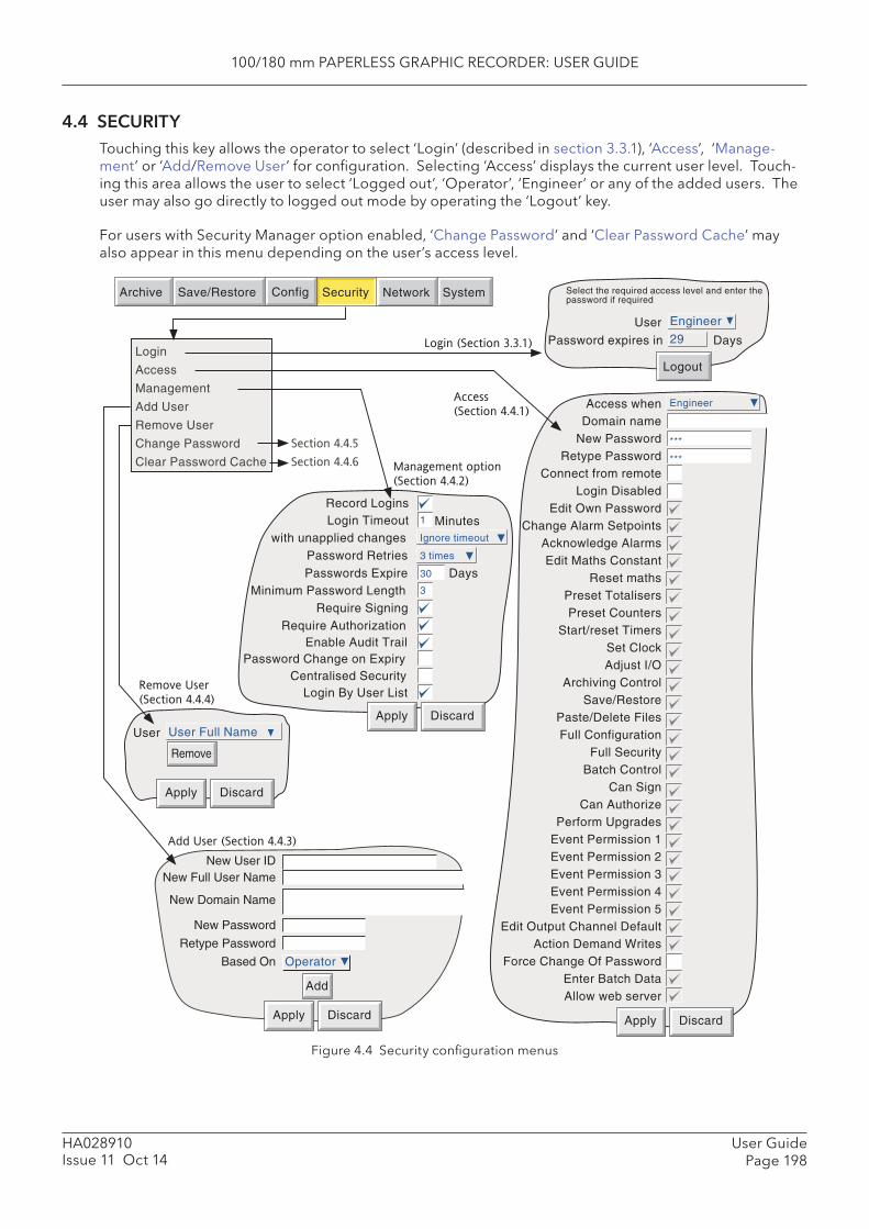
100/180 mm PAPERLESS GRAPHIC RECORDER: USER GUIDE
User GuidePage 198
HA028910Issue 11 Oct 14
4.4 SECURITYTouching this key allows the operator to select ‘Login’ (described in section 3.3.1), ‘Access’, ‘Manage-ment’ or ‘Add/Remove User’ for confi guration. Selecting ‘Access’ displays the current user level. Touch-ing this area allows the user to select ‘Logged out’, ‘Operator’, ‘Engineer’ or any of the added users. The user may also go directly to logged out mode by operating the ‘ Logout’ key.
For users with Security Manager option enabled, ‘ Change Password’ and ‘ Clear Password Cache’ may also appear in this menu depending on the user’s access level.
Figure 4.4 Security confi guration menus
Add User (Section 4.4.3)
Operator
Apply Discard
Add
New Full User NameNew User ID
New Domain Name
New Password
Retype Password
Based On
User User Full Name
Apply Discard
Remove
Remove User
(Section 4.4.4)
Engineer
***
***
Apply Discard
Access when Domain name
New Password Retype Password
Connect from remote Login Disabled
Edit Own Password Change Alarm Setpoints
Acknowledge Alarms Edit Maths Constant
Reset maths Preset Totalisers Preset Counters
Start/reset Timers Set Clock Adjust I/O
Archiving Control Save/Restore
Paste/Delete Files Full Configuration
Full Security Batch Control
Can Sign Can Authorize
Perform Upgrades Event Permission 1 Event Permission 2 Event Permission 3 Event Permission 4 Event Permission 5
Edit Output Channel Default Action Demand Writes
Force Change Of Password Enter Batch Data Allow web server
Access �
(Section 4.4.1)
Engineer
Logout
User29Password expires in Days
Select the required access level and enter the password if required
Archive SystemSave/Restore Config Security Network
Login (Section 3.3.1)
Management option �
(Section 4.4.2)
Login
Access
Management
Add User
Remove User
Change Password
Clear Password Cache
Record Logins
with unapplied changes
Minimum Password Length
Enable Audit TrailRequire Authorization
Apply Discard
Login Timeout
Password RetriesPasswords Expire
Require Signing
1
3 times
30 Days3
MinutesIgnore timeout
Password Change on ExpiryCentralised Security
Login By User List
Section 4.4.5
Section 4.4.6
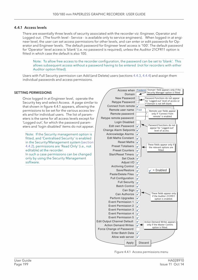
100/180 mm PAPERLESS GRAPHIC RECORDER: USER GUIDE
HA028910Issue 11 Oct 14
User GuidePage 199
4.4.1 Access levels
There are essentially three levels of security associated with the recorder viz: Engineer, Operator and Logged out. (The fourth level - Service - is available only to service engineers). When logged-in at engi-neer level, the user can set access permissions for other levels, and can enter or edit passwords for Op-erator and Engineer levels. The default password for Engineer level access is ‘100’. The default password for ‘Operator’ level access is ‘blank’ (i.e. no password is required), unless the Auditor 21CFR11 option is fi tted in which case the default is also 100.
Note: To allow free access to the recorder confi guration, the password can be set to ‘blank’. This allows subsequent access without a password having to be entered (not for recorders with either Auditor option fi tted).
Users with Full Security permission can Add (and Delete) users (sections 4.4.3, 4.4.4) and assign them individual passwords and access permissions.
Figure 4.4.1 Access permissions menu
Frederick BloggsAccess when Domain
New Password Retype Password
Connect from remote
Login Disabled
Change Alarm SetpointsEdit own Password
Remote user name Fred
Remote password
**
**
Retype remote password
Remote user fields appear
only if 'Connect from
remote' is enabled
Password functions do not
appear for 'Logged-out'
level of access.
Edit Maths Constant
Set Clock
Archiving ControlSave/Restore
Paste/Delete FilesFull Configuration
Full Security
= Enabled
Apply Discard
Batch Control
Preset Counters
Action Demand Writes appears
only if the Master Comms
option is fitted.
These fields appear only if
the relevant options are
fitted
Adjust I/O
Reset Maths
Preset Totalisers
Start/Reset Timers
Acknowledge Alarms
Can SignCan Authorize
Event Permission 1Event Permission 2Event Permission 3Event Permission 4Event Permission 5
Edit Output Channel DefaultAction Demand Writes
Force Change of Password
These fields appear only
if the Auditor 21CFR11
option is enabled.Perform Upgrades
Enter Batch DataAllow web server
Password functions do not appear
for 'Logged-out' level of access or
if Domain is not left blank.
Security Manager option is fittedSETTING PERMISSIONS
Once logged in at Engineer level, operate the Security key and select Access. A page similar to that shown in fi gure 4.4.1 appears, allowing the permissions to be set for the various access lev-els and for individual users. The list of param-eters is the same for all access levels except for ‘Logged out’, for which the password param-eters and ‘login disabled’ items do not appear.
Note: If the Security management option is fi tted, and ‘Centralised Security’ is enabled in the Security/Management system (section 4.4.2), permissions are ‘Read Only’ (i.e., not editable) at the recorder. In such a case permissions can be changed only by using the Security Management software.

100/180 mm PAPERLESS GRAPHIC RECORDER: USER GUIDE
User GuidePage 200
HA028910Issue 11 Oct 14
4.4.1 ACCESS LEVELS (Cont.)
ACCESS WHEN
Allows an access level or an individual Full User Name to be selected from a pick list.
DOMAIN NAME
For units fi tted with Security Manager option only, this allows a security domain name of up to 60 charac-ters to be entered, for the user selected in the ‘Access when’ fi eld. If the default (blank) is not edited, then the user can gain access using password setup in the ‘New password’ fi eld described below. If a new domain name is entered here, or if one already appears, the ‘New Password’ and ‘Retype Password’ fi elds are not displayed, and the user must use his or her network login password, as allocated by the user’s IT department or Network administrator.
Details of the Active Directory Server are entered in Network/Address confi guration (section 4.5.1). Pass-words can be edited as described in ‘Change Password’ (section 4.4.5)
If ‘Centralised security’ is enabled in the Security/Management menu (section 4.4.2) then the Domain name can be confi gured only using Security Manager software.
Note: An IP address must not be used as the domain name because to do so will disable the user’s ability to log in using Active Directory, even if there is a valid account on the server.
NEW PASSWORD/RETYPE PASSWORD
These fi elds do not appear if ‘Access when’ = ‘Logged Out’, or if the ‘Domain Name’ is anything other than left blank.
These fi elds allow a new password to be entered for the selected access level or User. The password must also be entered in the ‘Re-type Password’ fi eld. If the two differ, a warning message (Passwords did not match) appears when the APPLY key is operated, and password entry must be repeated. If the pass-word does not comply with the minimum length requirements in Security Management (if fi tted) (section 4.4.2), a warning message (Invalid Password) appears when the ‘Apply’ key is operated, and password entry must be repeated.
CONNECT FROM REMOTE
Enabling this fi eld, causes two further entry boxes: ‘Remote user name’ and ‘ Remote password’ to ap-pear. These items are used in establishing connection between a host computer and the recorder. The Remote user name is, by default, the Access Level (e.g. ‘Engineer’) or the User ID.
To make use of the Web server facility (Annex C), ‘Allow web server’ (below) must also be enabled.
REMOTE USER NAME/REMOTE PASSWORD
These two entry boxes allow user name and password to be entered for use by the remote host operator. The remote user will be able to access the recorder confi guration according to the other access permis-sions enabled in this page. The password must be entered twice to ensure integrity.
To allow unrestricted view-only to the host, ‘Logged out’ permission level should be selected and then a user name of ‘anonymous’ entered, and the password fi eld left blank.
Notes:1. Remote login will be refused if the user account is disabled for any reason.2. For maximum security, it is recommended that the remote password and the ‘local’ password
are non-identical.3. Attempts to establish a Bridge connection will fail if the relevant Remote User Name contains
characters with ASCII codes greater than 127 (such as é, è, a., ü etc.). Section B6 (Annex B) shows codes 0 to 127.

100/180 mm PAPERLESS GRAPHIC RECORDER: USER GUIDE
HA028910Issue 11 Oct 14
User GuidePage 201
4.4.1 ACCESS LEVELS (Cont.)
LOGIN DISABLED
For all levels except Logged Out, This allows any one or more of the access levels to be removed from the ‘Access when’ picklist.
Note: This feature should be used with discretion, or the situation might arise in which the record-er cannot be logged onto, either at a particular access level or at all. It is recommended that at least one user with Engineer-level access is retained with login enabled, or it may become neces-sary to return the recorder to the manufacturer, or to arrange for a service visit.
Auditor option notes:1. If the Auditor 21CFR11 option is fi tted, and the number of Password Retries is exceeded then
the relevant login is disabled. A user with Engineer level access can re-enable the login.2. If the Auditor 21CFR11 option is fi tted, and the Password Expire time has been exceeded, all
logins are disabled. In order to reconfi gure the recorder, it is necessary to use the Service pass-word - please contact the recorder supplier or the nearest service centre for advice.
EDIT OWN PASSWORD
Allows each user, with this permission enabled, to edit his/her password.
CHANGE ALARM SETPOINTS
Allows each user with this permission enabled, to edit alarm parameters under Confi guration/Channel
ACKNOWLEDGE ALARMS
Allows each user with this permission enabled to acknowledge alarms (section 3.1.4)
EDIT MATHS CONSTANT
For recorders fi tted with the Maths option only. If one or more maths channels are confi gured with func-tion ‘Constant’, then with this permission set, the user may edit the constant value(s).
RESET MATHS
Allows the user to reset applicable maths functions. See section 4.3.11 for further details of maths func-tions.
PRESET TOTALISERS
Allows the user to preset totaliser values (if the option is fi tted). See section 4.3.12 for further details of totalisers.
PRESET COUNTERS
Allows the user to preset counter values (if the option is fi tted). See section 4.3.13 for further details of Counters.
START/RESET TIMERS
Allows the user to start and reset the timer value. See section 4.3.14 for further details of timers.
SET CLOCK
Allows each user with this permission enabled, to set the recorder time and date functions under System/Clock
ADJUST I/O
Allows the user to adjust recorder inputs and outputs as described in section 4.6.4, and section 9 below.
100/180 mm PAPERLESS GRAPHIC RECORDER: USER GUIDE
User GuidePage 202
HA028910Issue 11 Oct 14
4.4.1 ACCESS LEVELS (Cont.)
ARCHIVING CONTROL
Allows each user with this permission enabled full access to archive control. For units fi tted with the lockable fl ap option, the fl ap may be unlocked only by users who have this Archiving Control permission enabled.
SAVE/RESTORE
Allows each user with this permission enabled, full access to saving and restoring functions as described in section 4.2, above. Without this permission, the SAVE/RESTORE key does not appear.
PASTE/DELETE FILES
Allows each user with this permission enabled, to Paste and Delete fi les as described in section 5.
FULL CONFIGURATION
Allows each user with this permission enabled, full access the recorder confi guration.
FULL SECURITY
Allows each user with this permission enabled, full access to all recorder security functions.
BATCH CONTROL
This fi eld appears only if the Batch Option (section 4.3.10) is fi tted. Allows the user to enter batch data and to start, stop and create new batches. If this access permission is set, ‘Enter Batch Data’ below, is automatically enabled and cannot be disabled.
CAN SIGN
This appears only if the Auditor 21CFR11 option is fi tted. If the fi eld is enabled it allows the user to change the confi guration of the recorder (according to the other permissions set for the login), providing the se-curity management system ‘Require Authorization’ is not enabled. If it is, changes can be made only if the correct password for a user with ‘Can Authorize’ permission is entered. See section 4.4.2 for details
CAN AUTHORIZE
This appears only if the Auditor 21CFR11 option is fi tted. If the fi eld is enabled it allows the user to change the confi guration of the recorder according to the permissions set for the login. See section 4.4.2 for details of the Auditor options.
PERFORM UPGRADES
‘Upgrade’ appears in the system menu only for access levels in which this box is ticked. Section 4.6.3 contains further details. Trial mode (section 4.3.22 ) can be enabled/disabled only by users with Perform Upgrades permission.
EVENT PERMISSION 1
If this is enabled, then this login will trigger an event source which remains active for as long as the login is active. See section 4.3.6 (Event Sources: User Logged In) for further details.
EVENT PERMISSION 2 TO 5
As for Event permission 1, above.
EDIT OUTPUT CHANNEL DEFAULT
Appears only if the Master Comms and/or Analogue output option is fi tted.When enabled, this allows a user with this login to edit the default value of any output channel. Normally the defaults are used only when the source channel is ‘In Error’.
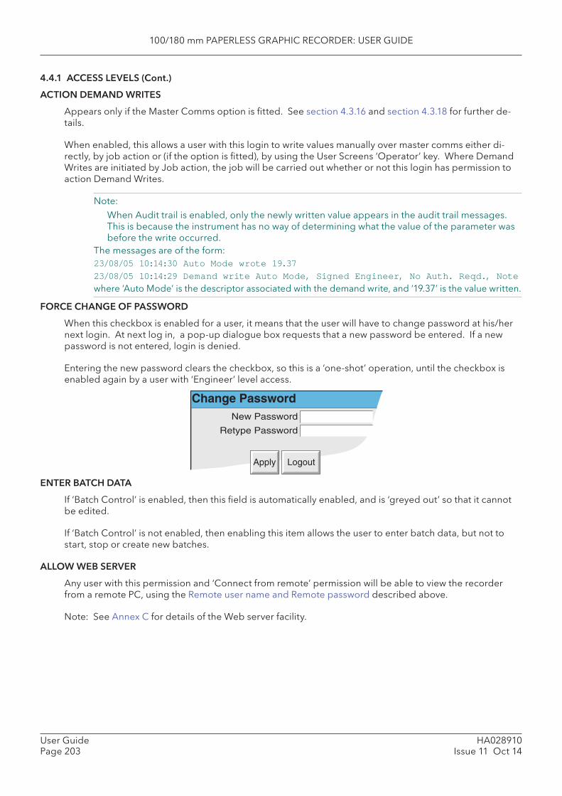
100/180 mm PAPERLESS GRAPHIC RECORDER: USER GUIDE
HA028910Issue 11 Oct 14
User GuidePage 203
4.4.1 ACCESS LEVELS (Cont.)
ACTION DEMAND WRITES
Appears only if the Master Comms option is fi tted. See section 4.3.16 and section 4.3.18 for further de-tails.
When enabled, this allows a user with this login to write values manually over master comms either di-rectly, by job action or (if the option is fi tted), by using the User Screens ‘Operator’ key. Where Demand Writes are initiated by Job action, the job will be carried out whether or not this login has permission to action Demand Writes.
Note: When Audit trail is enabled, only the newly written value appears in the audit trail messages.
This is because the instrument has no way of determining what the value of the parameter was before the write occurred.
The messages are of the form: 23/08/05 10:14:30 Auto Mode wrote 19.3723/08/05 10:14:29 Demand write Auto Mode, Signed Engineer, No Auth. Reqd., Notewhere ‘Auto Mode’ is the descriptor associated with the demand write, and ‘19.37’ is the value written.
FORCE CHANGE OF PASSWORD
When this checkbox is enabled for a user, it means that the user will have to change password at his/her next login. At next log in, a pop-up dialogue box requests that a new password be entered. If a new password is not entered, login is denied.
Entering the new password clears the checkbox, so this is a ‘one-shot’ operation, until the checkbox is enabled again by a user with ‘Engineer’ level access.
Change PasswordNew Password
Retype Password
Apply Logout
ENTER BATCH DATA
If ‘Batch Control’ is enabled, then this fi eld is automatically enabled, and is ‘greyed out’ so that it cannot be edited.
If ‘Batch Control’ is not enabled, then enabling this item allows the user to enter batch data, but not to start, stop or create new batches.
ALLOW WEB SERVER
Any user with this permission and ‘Connect from remote’ permission will be able to view the recorder from a remote PC, using the Remote user name and Remote password described above.
Note: See Annex C for details of the Web server facility.
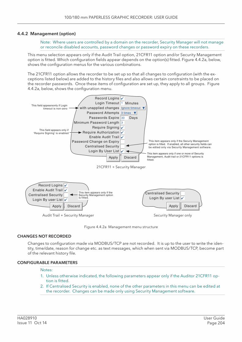
100/180 mm PAPERLESS GRAPHIC RECORDER: USER GUIDE
User GuidePage 204
HA028910Issue 11 Oct 14
4.4.2 Management (option)
Note: Where users are controlled by a domain on the recorder, Security Manager will not manage or reconcile disabled accounts, password changes or password expiry on these recorders.
This menu selection appears only if the Audit Trail option, 21CFR11 option and/or Security Management option is fi tted. Which confi guration fi elds appear depends on the option(s) fi tted. Figure 4.4.2a, below, shows the confi guration menus for the various combinations.
The 21CFR11 option allows the recorder to be set up so that all changes to confi guration (with the ex-ceptions listed below) are added to the history fi les and also allows certain constraints to be placed on the recorder passwords. Once these items of confi guration are set up, they apply to all groups. Figure 4.4.2a, below, shows the confi guration menu.
21CFR11 + Security Manager
Audit Trail + Security Manager Security Manager only
Figure 4.4.2a Management menu structure
CHANGES NOT RECORDED
Changes to confi guration made via MODBUS/TCP are not recorded. It is up to the user to write the iden-tity, time/date, reason for change etc. as text messages, which when sent via MODBUS/TCP, become part of the relevant history fi le.
CONFIGURABLE PARAMETERS
Notes:1. Unless otherwise indicated, the following parameters appear only if the Auditor 21CFR11 op-
tion is fi tted.2. If Centralised Security is enabled, none of the other parameters in this menu can be edited at
the recorder. Changes can be made only using Security Management software.
Record Logins
Centralised SecurityEnable Audit Trail
This item appears only if theSecurity Management optionis fitted.
Login By user List
Apply Discard
Record Logins
with unapplied changes
Minimum Password Length
Enable Audit TrailRequire Authorization
Apply Discard
Login Timeout
Password AttemptsPasswords Expire
Require Signing
1
3 times
30
3
Ignore timeout
Days
MinutesThis field appearsonly if Login
timeout is non-zero
Password Change on ExpiryCentralised Security
This field appears only if 'Require Signing' is enabled
Login By User List
This item appears only if the Securiy Managementoption is fitted. If enabled, all other security fields canbe edited only via Security Management software.
This item appears only if one or more of SecurityManagement, Audit trail or 21CFR11 options isfitted.
Centralised Security
Apply Discard
Login By user List

100/180 mm PAPERLESS GRAPHIC RECORDER: USER GUIDE
HA028910Issue 11 Oct 14
User GuidePage 205
4.4.2 MANAGEMENT (Cont.)
Record logins For either Auditor option, if this fi eld is enabled, then each time a new login occurs a message appears, giving the date, time and login name. E.G.
23/08/08 15:32:20 Login by Frederick Bloggs Logouts are recorded in a similar way - e.g. 23/08/08 15:49:43 Logout by Frederick Bloggs If the login or logout is via a ‘Bridge’ session (section 6), the IP address of that viewer
appears in the login/logout message - e.g. 23/08/05 15:58:03 Login by (149.121.130.126)Engineer Login Timout When set to zero, the login remains valid until changed. For any other value, the user
is logged out after the number of minutes entered here has elapsed since the last time the screen was touched.
with unapplied changesThis fi eld does not appear if the Login Timeout has been set to zero. For non-zero time-out values, this allows the user to choose whether
a any unapplied changes are lost when the Login Timeout period has elapsed, or b the login timeout is ignored if there are any unapplied confi guration changes.
Password Attempts For Active Directory users, this parameter is confi gured at the Active Directory and the value set at the instrument is ignored. For other users, this allows the user to limit to three, the number of attempt that can be made to enter a password. The choices are ‘3 times’ and ‘unlimited’. When set to 3 times, the user login is disabled after three incorrect attempts to enter the pass-word have been made. A ‘System Message’ appears on the screen and is also sent to the ‘chart’:
23/08/08 13:20:42 User Frederick Bloggs, login disabled, invalid password In order to re-enable the login, a user with Engineer access level must deselect
‘Login Disabled’ in the ‘Access’ menu described in section 4.4.1, above.
Passwords expire For Active Directory users, this parameter is confi gured at the Active Directory and the value set at the instrument is ignored. For other users, this fi eld allows the user to set an expiry period of up to 999 days which applies to all passwords. The number of days remaining to expiry is shown in the login page. If set to zero, then the expiry period does not apply.
Note: All required passwords MUST be changed within this number of days or all logins will be disabled In this situation, the confi guration of the recorder will be available only to those with Service Level access and in most cases, a call will have to be made to the recorder supplier or serv-ice agency. (But see ‘Password Change on Expiry’, below)
Minimum Password LengthFor Active Directory users, this parameter is confi gured at the Active Directory and the value set at the instrument is ignored. For other users, this allows a minimum length of password to be entered (default = 0; minimum = 3). If an attempt is made to enter a new password with fewer charac-ters than the minimum, a warning message appears on the screen (Invalid Password Length) and the new password is ignored. For Active Directory users, the password must comply with both the minimum length specifi ed here and that specifi ed in Ac-tive Directory.
Require Signing If this fi eld is enabled, then changes to the recorder operation, confi guration (or any other item included in the history fi le) can be made only by those users whose ‘Can Sign’ permission is enabled in the ‘Access’ menu described in section 4.4.1 above. When ‘Apply’ is attempted, a ‘signature’ page appears which requires the entry of the correct password for the selected user, and of a note which would normally be used to give the reason for the change.
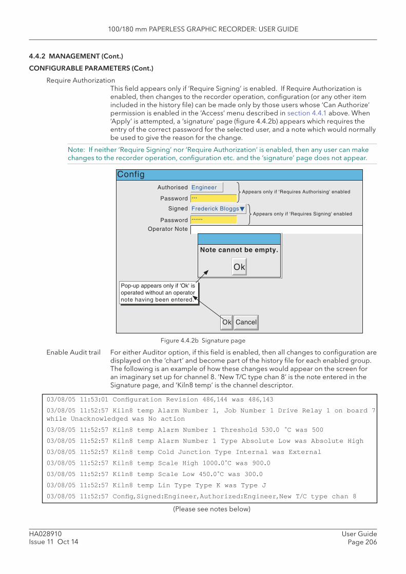
100/180 mm PAPERLESS GRAPHIC RECORDER: USER GUIDE
User GuidePage 206
HA028910Issue 11 Oct 14
4.4.2 MANAGEMENT (Cont.)
CONFIGURABLE PARAMETERS (Cont.)
Require AuthorizationThis fi eld appears only if ‘Require Signing’ is enabled. If Require Authorization is enabled, then changes to the recorder operation, confi guration (or any other item included in the history fi le) can be made only by those users whose ‘Can Authorize’ permission is enabled in the ‘Access’ menu described in section 4.4.1 above. When ‘Apply’ is attempted, a ‘signature’ page (fi gure 4.4.2b) appears which requires the entry of the correct password for the selected user, and a note which would normally be used to give the reason for the change.
Note: If neither ‘Require Signing’ nor ‘Require Authorization’ is enabled, then any user can make changes to the recorder operation, confi guration etc. and the ‘signature’ page does not appear.
Figure 4.4.2b Signature page
Enable Audit trail For either Auditor option, if this fi eld is enabled, then all changes to confi guration are displayed on the ‘chart’ and become part of the history fi le for each enabled group. The following is an example of how these changes would appear on the screen for an imaginary set up for channel 8. ‘New T/C type chan 8’ is the note entered in the Signature page, and ‘Kiln8 temp’ is the channel descriptor.
03/08/05 11:53:01 Confi guration Revision 486,144 was 486,143
03/08/05 11:52:57 Kiln8 temp Alarm Number 1, Job Number 1 Drive Relay 1 on board 7 while Unacknowledged was No action
03/08/05 11:52:57 Kiln8 temp Alarm Number 1 Threshold 530.0 C was 500
03/08/05 11:52:57 Kiln8 temp Alarm Number 1 Type Absolute Low was Absolute High
03/08/05 11:52:57 Kiln8 temp Cold Junction Type Internal was External
03/08/05 11:52:57 Kiln8 temp Scale High 1000.0 C was 900.0
03/08/05 11:52:57 Kiln8 temp Scale Low 450.0 C was 300.0
03/08/05 11:52:57 Kiln8 temp Lin Type Type K was Type J
03/08/05 11:52:57 Confi g,Signed:Engineer,Authorized:Engineer,New T/C type chan 8
(Please see notes below)
Operator Note
Signed Frederick Bloggs
Authorised Engineer
PasswordAppears only if 'Requires Authorising' enabled
***
******
Appears only if 'Requires Signing' enabled
Ok Cancel
Note cannot be empty.
Ok
Password
Config
Pop-up appears only if 'Ok' isoperated without an operatornote having been entered.
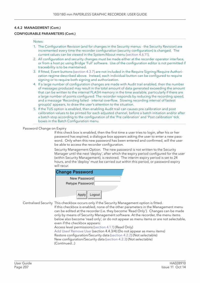
100/180 mm PAPERLESS GRAPHIC RECORDER: USER GUIDE
HA028910Issue 11 Oct 14
User GuidePage 207
4.4.2 MANAGEMENT (Cont.)
CONFIGURABLE PARAMETERS (Cont.)
Notes: 1. The Confi guration Revision (and for changes in the Security menus - the Security Revision) are
incremented every time the recorder confi guration (security confi guration) is changed. The current values can be viewed in the System/About menu (section 4.6.11).
2. All confi guration and security changes must be made either at the recorder operator interface, or from a host pc using Bridge ‘Full’ software. Use of the confi guration editor is not permitted if traceability is to be maintained.
3. If fi tted, Event buttons (section 4.3.7) are not included in the Require Signing/Require Authori-zation regime described above. Instead, each individual button can be confi gured to require signing or to require both signing and authorization.
4. If a large number of confi guration changes are made with Audit trail enabled, then the number of messages produced may result in the total amount of data generated exceeding the amount that can be written to the internal FLASH memory in the time available, particularly if there are a large number of points confi gured. The recorder responds by reducing the recording speed, and a message ‘ Recording failed - internal overfl ow. Slowing recording interval of fastest group(s)’ appears, to draw the user’s attention to the situation.
5. If the TUS option is enabled, then enabling Audit trail can causes pre calibration and post calibration values to be printed for each adjusted channel, before a batch initiation and/or after a batch stop according to the confi guration of the ‘Pre calibration’ and ‘Post calibration’ tick boxes in the Batch Confi guration menu.
Password Change on ExpiryIf this check box is enabled, then the fi rst time a user tries to login, after his or her password has expired, a dialogue box appears asking the user to enter a new pass-word. Only when this new password has been entered and confi rmed, will the user be able to access the recorder confi guration.
Security Management Option. The new password is not written to the Security Manager until the next ‘deploy’, after which the expiry period confi gured for the user (within Security Management), is restored. The interim expiry period is set to 24 hours, and the ‘deploy’ must be carried out within this period, or password expiry will recur.
Change PasswordNew Password
Retype Password
Apply Logout
Centralised Security This checkbox occurs only if the Security Management option is fi tted. If this checkbox is enabled, none of the other parameters in the Management menu
can be edited at the recorder (i.e. they become ‘Read Only’). Changes can be made only by means of Security Management software. At the recorder, the menu items below also become ‘read only’, or do not appear as menu items or are not selectable, even if the checkbox appears:
Access level permissions (section 4.1.1) (Read Only) Add User/ Remove User (section 4.4.3/4) (Do not appear as menu items) Restore confi guration/Security data (section 4.2.2) (Not selectable) New confi guration/Security data (section 4.2.3) (Not selectable) (Continued...)
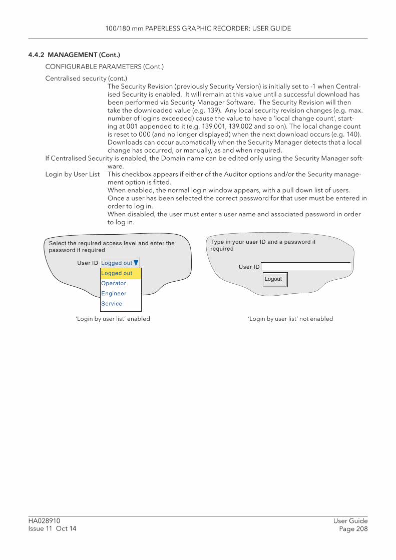
100/180 mm PAPERLESS GRAPHIC RECORDER: USER GUIDE
User GuidePage 208
HA028910Issue 11 Oct 14
4.4.2 MANAGEMENT (Cont.)
CONFIGURABLE PARAMETERS (Cont.)
Centralised security (cont.)The Security Revision (previously Security Version) is initially set to -1 when Central-ised Security is enabled. It will remain at this value until a successful download has been performed via Security Manager Software. The Security Revision will then take the downloaded value (e.g. 139). Any local security revision changes (e.g. max. number of logins exceeded) cause the value to have a ‘local change count’, start-ing at 001 appended to it (e.g. 139.001, 139.002 and so on). The local change count is reset to 000 (and no longer displayed) when the next download occurs (e.g. 140). Downloads can occur automatically when the Security Manager detects that a local change has occurred, or manually, as and when required.
If Centralised Security is enabled, the Domain name can be edited only using the Security Manager soft-ware.
Login by User List This checkbox appears if either of the Auditor options and/or the Security manage-ment option is fi tted.
When enabled, the normal login window appears, with a pull down list of users. Once a user has been selected the correct password for that user must be entered in order to log in.
When disabled, the user must enter a user name and associated password in order to log in.
Select the required access level and enter thepassword if required
User ID Logged out
Logged out
Operator
Engineer
Service
Type in your user ID and a password ifrequired
User ID
Logout
‘Login by user list’ enabled ‘Login by user list’ not enabled
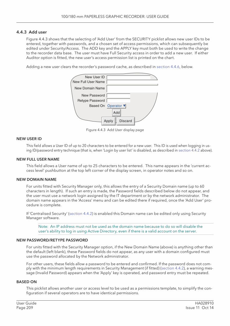
100/180 mm PAPERLESS GRAPHIC RECORDER: USER GUIDE
HA028910Issue 11 Oct 14
User GuidePage 209
4.4.3 Add user
Figure 4.4.3 shows that the selecting of ‘Add User’ from the SECURITY picklist allows new user IDs to be entered, together with passwords, and a chosen set of access permissions, which can subsequently be edited under Security/Access. The ADD key and the APPLY key must both be used to write the change to the recorder data base. The user must have Full Security access in order to add a new user. If either Auditor option is fi tted, the new user’s access permission list is printed on the chart.
Adding a new user clears the recorder’s password cache, as described in section 4.4.6, below.
Figure 4.4.3 Add User display page
NEW USER ID
This fi eld allows a User ID of up to 20 characters to be entered for a new user. This ID is used when logging in us-ing ID/password entry technique (that is, when ‘Login by user list’ is disabled, as described in section 4.4.2 above).
NEW FULL USER NAME
This fi eld allows a User name of up to 25 characters to be entered. This name appears in the ‘current ac-cess level’ pushbutton at the top left corner of the display screen, in operator notes and so on.
NEW DOMAIN NAME
For units fi tted with Security Manager only, this allows the entry of a Security Domain name (up to 60 characters in length). If such an entry is made, the Password fi elds described below do not appear, and the user must use a network login assigned by the IT department or by the network administrator. The domain name appears in the ‘Access’ menu and can be edited there if required, once the ‘Add User’ pro-cedure is complete.
If ‘Centralised Security’ (section 4.4.2) is enabled this Domain name can be edited only using Security Manager software.
Note: An IP address must not be used as the domain name because to do so will disable the user’s ability to log in using Active Directory, even if there is a valid account on the server.
NEW PASSWORD/RETYPE PASSWORD
For units fi tted with the Security Manager option, if the New Domain Name (above) is anything other than the default (left blank), these Password fi elds do not appear, as any user with a domain confi gured must use the password allocated by the Network administrator.
For other users, these fi elds allow a password to be entered and confi rmed. If the password does not com-ply with the minimum length requirements in Security Management (if fi tted) (section 4.4.2), a warning mes-sage (Invalid Password) appears when the ‘Apply’ key is operated, and password entry must be repeated.
BASED ON
This picklist allows another user or access level to be used as a permissions template, to simplify the con-fi guration if several operators are to have identical permissions.
Operator
Apply Discard
Add
New Full User NameNew User ID
New Domain Name
New Password
Retype Password
Based On
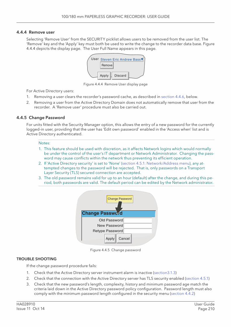
100/180 mm PAPERLESS GRAPHIC RECORDER: USER GUIDE
User GuidePage 210
HA028910Issue 11 Oct 14
Figure 4.4.4 Remove User display page
For Active Directory users:1. Removing a user clears the recorder’s password cache, as described in section 4.4.6, below.2. Removing a user from the Active Directory Domain does not automatically remove that user from the
recorder. A ‘Remove user’ procedure must also be carried out.
4.4.5 Change Password
For units fi tted with the Security Manager option, this allows the entry of a new password for the currently logged-in user, providing that the user has ‘Edit own password’ enabled in the ‘Access when’ list and is Active Directory authenticated.
Notes: 1. This feature should be used with discretion, as it affects Network logins which would normally
be under the control of the user’s IT department or Network Administrator. Changing the pass-word may cause confl icts within the network thus preventing its effi cient operation.
2. If ‘Active Directory security’ is set to ‘None’ (section 4.5.1: Network/Address menu), any at-tempted changes to the password will be rejected. That is, only passwords on a Transport Layer Security (TLS) secured connection are accepted.
3. The old password remains valid for up to an hour (default) after the change, and during this pe-riod, both passwords are valid. The default period can be edited by the Network administrator.
4.4.4 Remove user
Selecting ‘Remove User’ from the SECURITY picklist allows users to be removed from the user list. The ‘Remove’ key and the ‘Apply’ key must both be used to write the change to the recorder data base. Figure 4.4.4 depicts the display page. The User Full Name appears in this page.
User Steven Eric Andrew Bass
Apply Discard
Remove
Figure 4.4.5 Change password
TROUBLE SHOOTING
If the change password procedure fails:
1. Check that the Active Directory server instrument alarm is inactive (section3.1.3)2. Check that the connection with the Active Directory server has TLS security enabled (section 4.5.1)3. Check that the new password’s length, complexity, history and minimum password age match the
criteria laid down in the Active Directory password policy confi guration. Password length must also comply with the minimum password length confi gured in the security menu (section 4.4.2)
Change PasswordOld Password
New Password
Apply Cancel
Change Password
Retype Password
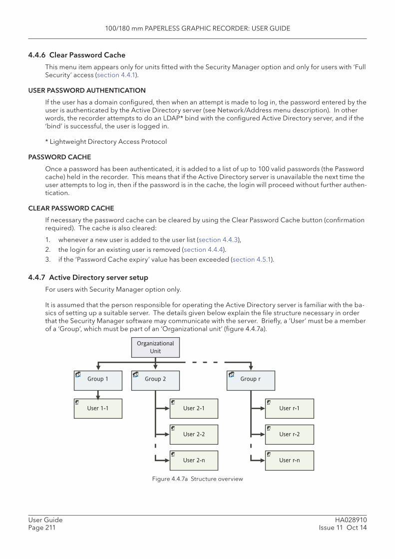
100/180 mm PAPERLESS GRAPHIC RECORDER: USER GUIDE
HA028910Issue 11 Oct 14
User GuidePage 211
4.4.6 Clear Password Cache
This menu item appears only for units fi tted with the Security Manager option and only for users with ‘Full Security’ access (section 4.4.1).
USER PASSWORD AUTHENTICATION
If the user has a domain confi gured, then when an attempt is made to log in, the password entered by the user is authenticated by the Active Directory server (see Network/Address menu description). In other words, the recorder attempts to do an LDAP* bind with the confi gured Active Directory server, and if the ‘bind’ is successful, the user is logged in.
* Lightweight Directory Access Protocol
PASSWORD CACHE
Once a password has been authenticated, it is added to a list of up to 100 valid passwords (the Password cache) held in the recorder. This means that if the Active Directory server is unavailable the next time the user attempts to log in, then if the password is in the cache, the login will proceed without further authen-tication.
CLEAR PASSWORD CACHE
If necessary the password cache can be cleared by using the Clear Password Cache button (confi rmation required). The cache is also cleared:
1. whenever a new user is added to the user list (section 4.4.3),2. the login for an existing user is removed (section 4.4.4). 3. if the ‘Password Cache expiry’ value has been exceeded (section 4.5.1).
4.4.7 Active Directory server setup
For users with Security Manager option only.
It is assumed that the person responsible for operating the Active Directory server is familiar with the ba-sics of setting up a suitable server. The details given below explain the fi le structure necessary in order that the Security Manager software may communicate with the server. Briefl y, a ‘User’ must be a member of a ‘Group’, which must be part of an ‘Organizational unit’ (fi gure 4.4.7a).
User 2-1
Group 2
User 1-1
Group 1
User 2-2
User 2-n
Group r
User r-1
User r-2
User r-n
Organizational �
Unit
Figure 4.4.7a Structure overview
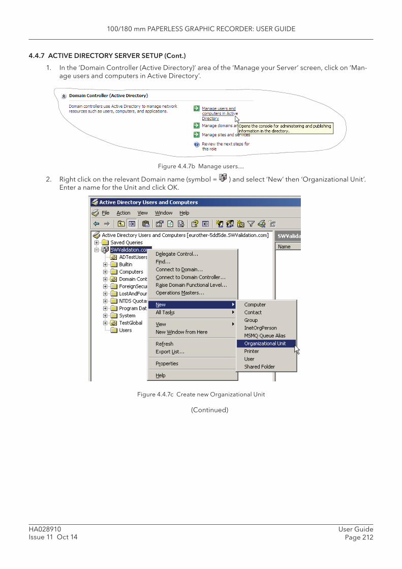
100/180 mm PAPERLESS GRAPHIC RECORDER: USER GUIDE
User GuidePage 212
HA028910Issue 11 Oct 14
4.4.7 ACTIVE DIRECTORY SERVER SETUP (Cont.)
1. In the ‘Domain Controller (Active Directory)’ area of the ‘Manage your Server’ screen, click on ‘Man-age users and computers in Active Directory’.
Figure 4.4.7b Manage users....
2. Right click on the relevant Domain name (symbol = ) and select ‘New’ then ‘Organizational Unit’. Enter a name for the Unit and click OK.
Figure 4.4.7c Create new Organizational Unit
(Continued)
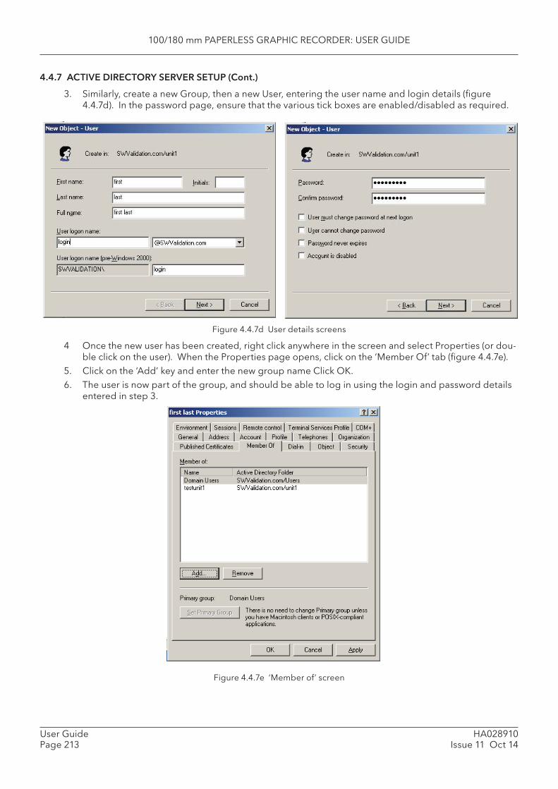
100/180 mm PAPERLESS GRAPHIC RECORDER: USER GUIDE
HA028910Issue 11 Oct 14
User GuidePage 213
4.4.7 ACTIVE DIRECTORY SERVER SETUP (Cont.)
3. Similarly, create a new Group, then a new User, entering the user name and login details (fi gure 4.4.7d). In the password page, ensure that the various tick boxes are enabled/disabled as required.
Figure 4.4.7d User details screens
4 Once the new user has been created, right click anywhere in the screen and select Properties (or dou-ble click on the user). When the Properties page opens, click on the ‘Member Of’ tab (fi gure 4.4.7e).
5. Click on the ‘Add’ key and enter the new group name Click OK.6. The user is now part of the group, and should be able to log in using the login and password details
entered in step 3.
Figure 4.4.7e ‘Member of’ screen
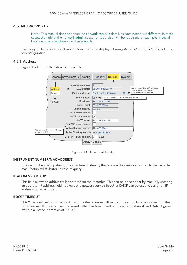
100/180 mm PAPERLESS GRAPHIC RECORDER: USER GUIDE
User GuidePage 214
HA028910Issue 11 Oct 14
4.5 NETWORK KEY
Note: This manual does not describe network setup in detail, as each network is different. In most cases, the help of the network administrator or supervisor will be required, for example, in the al-location of valid addresses and passwords.
Touching the Network key calls a selection box to the display, allowing ‘Address’ or ‘Name’ to be selected for confi guration.
4.5.1 Address
Figure 4.5.1 shows the address menu fi elds.
Figure 4.5.1 Network addressing
INSTRUMENT NUMBER/ MAC ADDRESS
Unique numbers set up during manufacture to identify the recorder to a remote host, or to the recorder manufacturer/distributor, in case of query.
IP ADDRESS LOOKUP
This fi eld allows an address to be entered for the recorder. This can be done either by manually entering an address (IP address fi eld - below), or a network service BootP or DHCP can be used to assign an IP address to the recorder.
BOOTP TIMEOUT
This 28 second period is the maximum time the recorder will wait, at power-up, for a response from the BootP server. If no response is received within this time, the IP address, Subnet mask and Default gate-way are all set to, or remain at 0.0.0.0
Archive Save/Restore Config Security Network System
MAC address
IP address lookup
IP address
Subnet mask 255.255.255.0
Default gateway 0.0.0.0
192.168.111.222
Instrument number 240
08:00:48:80:00:F0
Get from BootP Server
Fig 4.5.2
BootP timeout 28 s
SNTP server enable
SNTP server 149.121.128.179
SNTP client enable
Appear only if Security Manager
option enabled.
Appears only for 'Get from BootP Server'
Address Name
EuroPRP server enable
Active Directory server 123.456.234.1
Active Directory security TLS (port 636)
Select 'specify an IP address', 'Get from BootP Server' or 'Get from DHCP Server'
Password Cache expiry
Apply Discard
Days0
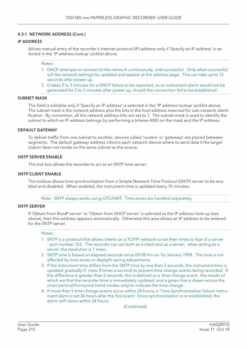
100/180 mm PAPERLESS GRAPHIC RECORDER: USER GUIDE
HA028910Issue 11 Oct 14
User GuidePage 215
4.5.1 NETWORK ADDRESS (Cont.)
IP ADDRESS
Allows manual entry of the recorder’s internet protocol (IP) address only if ‘Specify an IP address’ is se-lected in the ‘IP address lookup’ picklist above.
Notes:1. DHCP attempts to connect to the network continuously, until successful. Only when successful
will the network settings be updated and appear at the address page. This can take up to 13 seconds after power up.
2. It takes 2 to 3 minutes for a DHCP failure to be reported, so an instrument alarm would not be generated for 2 to 3 minutes after power up, should the connection fail to be established.
SUBNET MASK
This fi eld is editable only if ‘Specify an IP address’ is selected in the ‘IP address lookup’ picklist above. The subnet mask is the network address plus the bits in the host address reserved for sub-network identi-fi cation. By convention, all the network address bits are set to 1. The subnet mask is used to identify the subnet to which an IP address belongs by performing a bitwise AND on the mask and the IP address.
DEFAULT GATEWAY
To deliver traffi c from one subnet to another, devices called ‘routers’ or ‘gateways’ are placed between segments. The default gateway address informs each network device where to send data if the target station does not reside on the same subnet as the source.
SNTP SERVER ENABLE
This tick box allows the recorder to act as an SNTP time server.
SNTP CLIENT ENABLE
This tickbox allows time synchronisation from a Simple Network Time Protocol (SNTP) server to be ena-bled and disabled. When enabled, the instrument time is updated every 15 minutes.
Note: SNTP always works using UTC/GMT. Time zones are handled separately.
SNTP SERVER
If ‘Obtain from BootP server’ or ‘Obtain from DHCP server’ is selected as the IP address look-up (see above), then this address appears automatically. Otherwise this area allows an IP address to be entered for the SNTP server.
Notes:1 SNTP is a protocol that allows clients on a TCP/IP network to set their times to that of a server
- port number 123. The recorder can act both as a client and as a server; when acting as a server, the resolution is 1 msec.
2. SNTP time is based on elapsed seconds since 00:00 hrs on 1st January 1900. The time is not affected by time zones or daylight saving adjustments.
3. If the instrument time differs from the SNTP time by less than 2 seconds, the instrument time is updated gradually (1 msec 8 times a second) to prevent time change events being recorded. If the difference is greater than 2 seconds, this is defi ned as a ‘time change event’, the results of which are that the recorder time is immediately updated, and a green line is drawn across the chart (vertical/horizontal trend modes only) to indicate the time change.
4. If more than 5 time change events occur within 24 hours, a ‘Time Synchronisation failure’ instru-ment alarm is set 24 hours after the fi rst event. Once synchronisation is re-established, the alarm self-clears within 24 hours.
(Continued)
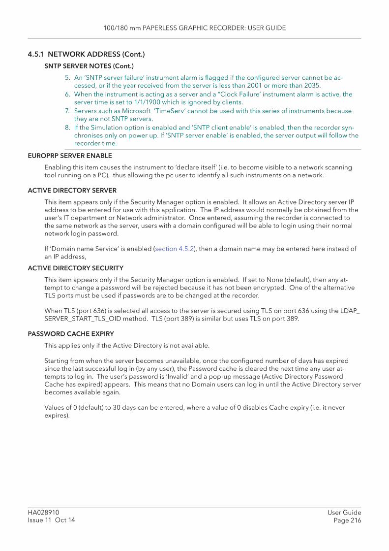
100/180 mm PAPERLESS GRAPHIC RECORDER: USER GUIDE
User GuidePage 216
HA028910Issue 11 Oct 14
4.5.1 NETWORK ADDRESS (Cont.)
SNTP SERVER NOTES (Cont.)
5. An ‘SNTP server failure’ instrument alarm is fl agged if the confi gured server cannot be ac-cessed, or if the year received from the server is less than 2001 or more than 2035.
6. When the instrument is acting as a server and a “Clock Failure’ instrument alarm is active, the server time is set to 1/1/1900 which is ignored by clients.
7. Servers such as Microsoft ‘TimeServ’ cannot be used with this series of instruments because they are not SNTP servers.
8. If the Simulation option is enabled and ‘SNTP client enable’ is enabled, then the recorder syn-chronises only on power up. If ‘SNTP server enable’ is enabled, the server output will follow the recorder time.
EUROPRP SERVER ENABLE
Enabling this item causes the instrument to ‘declare itself’ (i.e. to become visible to a network scanning tool running on a PC), thus allowing the pc user to identify all such instruments on a network.
ACTIVE DIRECTORY SERVER
This item appears only if the Security Manager option is enabled. It allows an Active Directory server IP address to be entered for use with this application. The IP address would normally be obtained from the user’s IT department or Network administrator. Once entered, assuming the recorder is connected to the same network as the server, users with a domain confi gured will be able to login using their normal network login password.
If ‘Domain name Service’ is enabled (section 4.5.2), then a domain name may be entered here instead of an IP address,
ACTIVE DIRECTORY SECURITY
This item appears only if the Security Manager option is enabled. If set to None (default), then any at-tempt to change a password will be rejected because it has not been encrypted. One of the alternative TLS ports must be used if passwords are to be changed at the recorder.
When TLS (port 636) is selected all access to the server is secured using TLS on port 636 using the LDAP_SERVER_START_TLS_OID method. TLS (port 389) is similar but uses TLS on port 389.
PASSWORD CACHE EXPIRY
This applies only if the Active Directory is not available.
Starting from when the server becomes unavailable, once the confi gured number of days has expired since the last successful log in (by any user), the Password cache is cleared the next time any user at-tempts to log in. The user’s password is ‘Invalid’ and a pop-up message (Active Directory Password Cache has expired) appears. This means that no Domain users can log in until the Active Directory server becomes available again.
Values of 0 (default) to 30 days can be entered, where a value of 0 disables Cache expiry (i.e. it never expires).
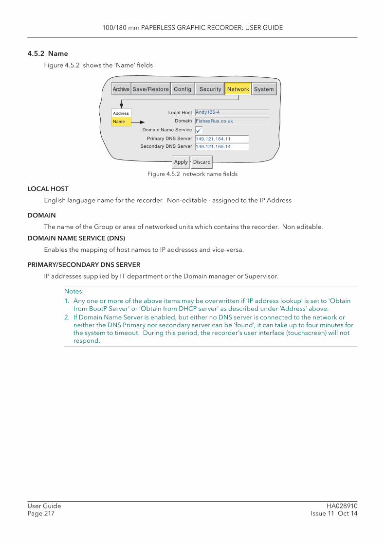
100/180 mm PAPERLESS GRAPHIC RECORDER: USER GUIDE
HA028910Issue 11 Oct 14
User GuidePage 217
Address
Name
Archive Save/Restore Config Security Network System
Domain Name Service
Primary DNS Server
Secondary DNS Server
Local Host Andy136-4
149.121.164.11
149.121.165.14
Apply Discard
Domain FishesRus.co.uk
4.5.2 Name
Figure 4.5.2 shows the ‘Name’ fi elds
Figure 4.5.2 network name fi elds
LOCAL HOST
English language name for the recorder. Non-editable - assigned to the IP Address
DOMAIN
The name of the Group or area of networked units which contains the recorder. Non editable.
DOMAIN NAME SERVICE (DNS)
Enables the mapping of host names to IP addresses and vice-versa.
PRIMARY/SECONDARY DNS SERVER
IP addresses supplied by IT department or the Domain manager or Supervisor.
Notes: 1. Any one or more of the above items may be overwritten if ‘IP address lookup’ is set to ‘Obtain
from BootP Server’ or ‘Obtain from DHCP server’ as described under ‘Address’ above.2. If Domain Name Server is enabled, but either no DNS server is connected to the network or
neither the DNS Primary nor secondary server can be ‘found’, it can take up to four minutes for the system to timeout. During this period, the recorder’s user interface (touchscreen) will not respond.
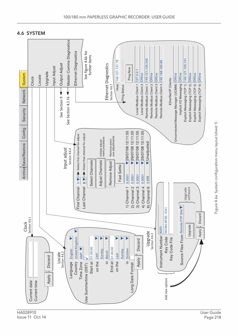
100/180 mm PAPERLESS GRAPHIC RECORDER: USER GUIDE
User GuidePage 218
HA028910Issue 11 Oct 14
4.6 SYSTEM
Fig
ure
4.6a
Sys
tem
co
nfi g
urat
ion
men
u la
you
t (sh
eet 1
)
Ho
st
Pin
g S
tatu
s
14
9.1
21
.13
1.7
8
Ho
st R
ea
cha
ble
Pin
g N
ow
Lo
cal M
od
bu
s C
lien
t 1
Lo
cal M
od
bu
s C
lien
t 2
Re
mo
te M
od
bu
s C
lien
t 1
Re
mo
te M
od
bu
s C
lien
t 2
Re
mo
te M
od
bu
s C
lien
t 3
Re
mo
te M
od
bu
s C
lien
t 4
12
7.0
.0.1
Off
line
14
9.1
21
.13
0.2
42
Off
line
Off
line
19
2.1
68
.18
9.8
9
Un
con
ne
cte
d M
ess
ag
e M
an
ag
er
(UC
MM
)
Imp
licit
I/O
Me
ssa
gin
g
Exp
licit
Me
ssa
gin
g (
TC
P 1
)
Exp
licit
Me
ssa
gin
g (
TC
P 2
)
Exp
licit
Me
ssa
gin
g (
TC
P 3
)
Exp
licit
Me
ssa
gin
g (
TC
P 4
)
Off
line
Off
line
14
9.1
21
.12
9.1
41
Off
line
Off
line
Off
line
Eth
erN
et/
IP C
lien
ts:
Fir
st C
ha
nn
el
1S
ele
ct f
irst
ch
an
ne
l fo
r a
dju
st
La
st C
ha
nn
el
6S
ele
ct f
ina
l ch
an
ne
l fo
r a
dju
st
Initi
ate
ad
just
-m
en
t p
roce
du
re
1)
Ch
an
ne
l 1
2)
Ch
an
ne
l 23
) C
ha
nn
el 3
4)
Ch
an
ne
l 4
Re
mo
ve p
revi
-o
us
ad
just
me
nts
6)
Ch
an
ne
l 6
29/0
7/08
12:
11:5
529
/07/
08 1
2:11
:55
29/0
7/08
12:
11:5
529
/07/
08 1
2:11
:55
Un
ad
just
ed
5.0
00
1
5.0
00
1
5.0
00
1
5.0
00
1
4.9
98
Adj
ust C
hann
els
Rem
ove
Adj
ust
Sel
ect C
hann
els
Fas
t Set
tleInput
adju
st
Section 4
.6.4
La
ng
ua
ge
Co
un
try
Tim
e Z
on
e
Use
Su
mm
ert
ime
(D
ST
)S
tart
at
on
th
e inE
nd
at
on
th
e in
En
glis
h
Un
ited
Kin
gd
om
GM
T
01
:00
:00
La
st
Su
nd
ay
Ma
rch
01
:00
:00
La
st
Su
nd
ay
Oct
ob
er
Lo
ng
Da
te F
orm
at
Ap
ply
Dis
card
Locale
Section 4
.6.2
Section 4
.6.3
Upgra
deC
lock
Cu
rre
nt
da
teC
urr
en
t tim
e Ap
ply
Dis
card
Arc
hiv
eS
ave
/Re
sto
reC
on
figS
ecu
rity
Ne
two
rkS
yste
m
Section 4
.6.1
See S
ection 4
.3.1
6
See f
igure
4.6
b f
or
�
furt
her
item
s
Eth
ern
et
Dia
gnost
ics
Section 4
.6.7
See S
ection 9
Inst
rum
en
t N
um
be
rK
ey
Co
de
82
03
WC
8N
-9F
5E
-1D
41
Ap
ply
Dis
card
Ke
y C
od
e F
ile
So
urc
e F
iles
Fro
mR
em
ote
FT
P S
ite
Up
gra
de
Add n
ew
options
Up
grad
e �
so
ftw
are
Clo
ck
Lo
cale
U
pg
rad
e
Inp
ut
Ad
just
O
utp
ut
Ad
just
M
ast
er
Co
mm
s D
iag
no
stic
s E
the
rne
t D
iag
no
stic
s
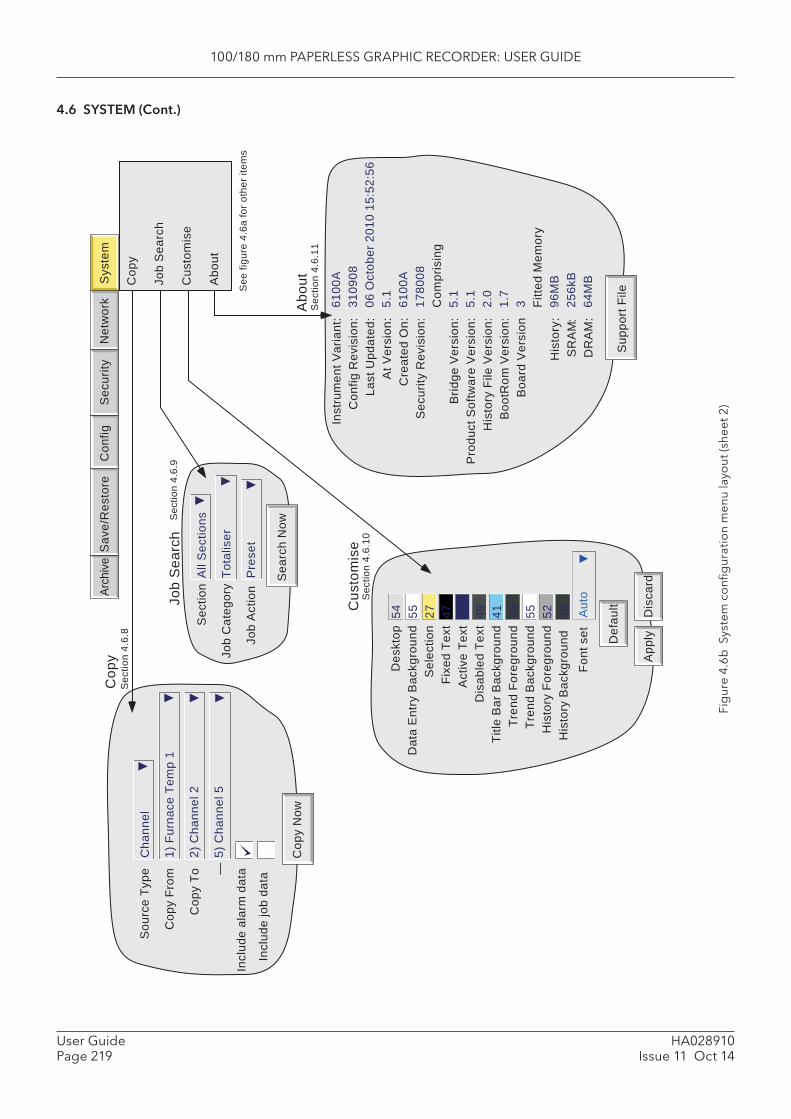
100/180 mm PAPERLESS GRAPHIC RECORDER: USER GUIDE
HA028910Issue 11 Oct 14
User GuidePage 219
4.6 SYSTEM (Cont.)
Fig
ure
4.6b
Sys
tem
co
nfi g
urat
ion
men
u la
you
t (sh
eet 2
)
Inst
rum
ent V
aria
nt:
Con
fig R
evis
ion:
Last
Upd
ated
:A
t Ver
sion
:C
reat
ed O
n:S
ecur
ity R
evis
ion:
Brid
ge V
ersi
on:
Pro
duct
Sof
twar
e V
ersi
on:
His
tory
File
Ver
sion
:B
ootR
om V
ersi
on:
Boa
rd V
ersi
on
His
tory
:S
RA
M:
DR
AM
:
6100
A31
0908
06 O
ctob
er 2
010
15:5
2:56
5.1
6100
A17
8008
Com
pris
ing
5.1
5.1
2.0
1.7
3 Fitte
d M
emor
y96
MB
256k
B64
MB
Sup
port
File
Abo
utS
ectio
n 4.
6.11
Cop
y N
ow
Cha
nnel
1) F
urna
ce T
emp
1
2) C
hann
el 2
5) C
hann
el 5
Sou
rce
Type
Cop
y Fr
om
Cop
y To —
Incl
ude
alar
m d
ata
Incl
ude
job
data
Cop
yS
ectio
n 4.
6.8
Arch
ive
Sav
e/R
esto
reC
onfig
Sec
urity
Net
wor
kS
yste
m
Cop
y
Job
Sea
rch
Cus
tom
ise
Abo
ut
See
figu
re 4
.6a
for o
ther
item
s
Sea
rch
Now
All
Sec
tions
Tota
liser
Pre
set
Sec
tion
Job
Cat
egor
y
Job
Act
ion
Job
Sea
rch
Sec
tion
4.6.
9
Des
ktop
Dat
a E
ntry
Bac
kgro
und
Sel
ectio
nFi
xed
Text
Act
ive
Text
Dis
able
d Te
xtTi
tle B
ar B
ackg
roun
dTr
end
Fore
grou
ndTr
end
Bac
kgro
und
His
tory
For
egro
und
His
tory
Bac
kgro
und
54 55 27 47 6 49 41 48 55 52 48Fo
nt s
etA
uto
Def
ault
App
lyD
isca
rd
Cus
tom
ise
Sec
tion
4.6.
10

100/180 mm PAPERLESS GRAPHIC RECORDER: USER GUIDE
User GuidePage 220
HA028910Issue 11 Oct 14
4.6 SYSTEM (Cont.)
Touching the System key calls the pick list: Clock, Locale, Upgrade, Input adjust, Master Comms Diagnos-tics (if option fi tted), Ethernet diagnostics, Copy, Job search, About.
Figures 4.6a and 4.6b above, give an overview of the System Menus.
4.6.1 Clock
Selecting ‘clock’ causes the recorder’s date and time to be displayed. To edit the date, touch the current date area, to call the keyboard and enter the new numbers. The date is edited in a similar way. The set-tings apply as soon as the ‘Apply settings’ button is touched. See also SNTP details in section 4.5.1.
4.6.2 Locale
This allows the setting of the following items:
Language Choose the required language from the picklist Country Displays a pick list of countries associated with the selected language Time zone* Select required time zone from picklist. Use Summertime ( DST)* Select box if daylight saving is to be used, If ‘Use Summertime (DST)’ is selected, the
times and dates for the start and end of summertime can be entered using picklists - see fi gure 4.6a.
Notes1 Date format DD/MM/YY or MM/DD/YY is defi ned by the language and country selected. Time
format (e.g. 12/24 hr. clock) is defi ned by the country selected.2. When using Bridge software, the host PC’s locale information and the recorder locale informa-
tion should match, or the displayed time will not be correct.
*Note: For more information, see B7 Annex B and/or http://www.timeanddate.com
LONG DATE FORMAT
Table 4.6.2 shows some examples of the Standard and Long Format date layouts which are available ac-cording to Language and Country selections.
Table 4.6.2 Date format examples
Argentina 01/05/06 01/05/2006
Australia 1/05/06 1/05/2006
Bolivia 01-05-06 01-05-2006
Canada (Eng) 01/05/06 1-May-06
Canada (Fra) 06-05-01 06-05-01
France 01/05/06 1 mai 06
Germany 01.05.06 01.05.2006
Holland 1-5-06 1-mei-06
Italy 01/05/06 1-Mag-06
Portugal 01-05-2006 1/Mai/06
South Africa 06/05/01 2006/05/01
Spain 1/05/06 01-may-06
Switzerland (Fra) 01.05.06 1 mai 06
Switzerland (Ger) 01.05.06 01.05.2006
Switzerland (Ita) 01.05.06 1-mag-06
United Kingdom 01/05/06 01-May-06
United States 5/1/06 01-May-06
Uruguay 01/05/06 01/05/2006
Country
(Language) Standard Long Format
Date display
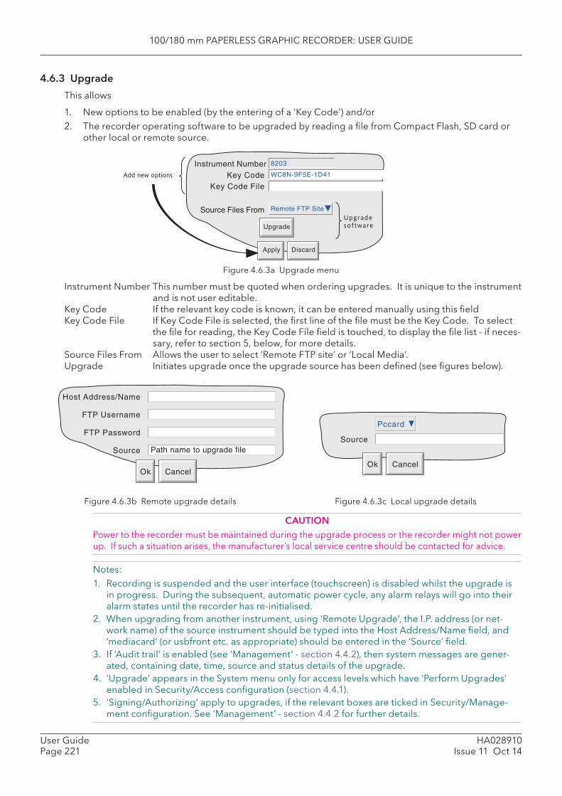
100/180 mm PAPERLESS GRAPHIC RECORDER: USER GUIDE
HA028910Issue 11 Oct 14
User GuidePage 221
4.6.3 Upgrade
This allows
1. New options to be enabled (by the entering of a ‘Key Code’) and/or 2. The recorder operating software to be upgraded by reading a fi le from Compact Flash, SD card or
other local or remote source.
Figure 4.6.3a Upgrade menu
Instrument Number This number must be quoted when ordering upgrades. It is unique to the instrument and is not user editable.
Key Code If the relevant key code is known, it can be entered manually using this fi eld Key Code File If Key Code File is selected, the fi rst line of the fi le must be the Key Code. To select
the fi le for reading, the Key Code File fi eld is touched, to display the fi le list - if neces-sary, refer to section 5, below, for more details.
Source Files From Allows the user to select ‘Remote FTP site’ or ‘Local Media’. Upgrade Initiates upgrade once the upgrade source has been defi ned (see fi gures below).
Instrument NumberKey Code
8203
WC8N-9F5E-1D41
Apply Discard
Key Code File
Source Files From Remote FTP Site
Upgrade
Add new options
Upgrade
software
Figure 4.6.3b Remote upgrade details Figure 4.6.3c Local upgrade details
CAUTIONPower to the recorder must be maintained during the upgrade process or the recorder might not power up. If such a situation arises, the manufacturer’s local service centre should be contacted for advice.
Notes:1. Recording is suspended and the user interface (touchscreen) is disabled whilst the upgrade is
in progress. During the subsequent, automatic power cycle, any alarm relays will go into their alarm states until the recorder has re-initialised.
2. When upgrading from another instrument, using ‘Remote Upgrade’, the I.P. address (or net-work name) of the source instrument should be typed into the Host Address/Name fi eld, and ‘media card’ (or usbfront etc. as appropriate) should be entered in the ‘Source’ fi eld.
3. If ‘Audit trail’ is enabled (see ‘Management’ - section 4.4.2), then system messages are gener-ated, containing date, time, source and status details of the upgrade.
4. ‘Upgrade’ appears in the System menu only for access levels which have ‘Perform Upgrades’ enabled in Security/Access confi guration (section 4.4.1).
5. ‘Signing/Authorizing’ apply to upgrades, if the relevant boxes are ticked in Security/Manage-ment confi guration. See ‘Management’ - section 4.4.2 for further details.
Host Address/Name
Ok Cancel
FTP Username
FTP Password
Source Path name to upgrade file
Ok Cancel
Source
Pccard
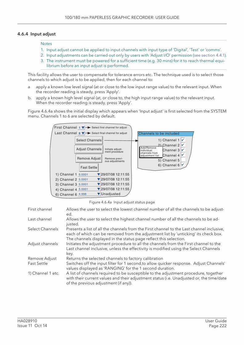
100/180 mm PAPERLESS GRAPHIC RECORDER: USER GUIDE
User GuidePage 222
HA028910Issue 11 Oct 14
4.6.4 Input adjust
Notes1. Input adjust cannot be applied to input channels with input type of ‘Digital’, ‘Test’ or ‘comms’.2. Input adjustments can be carried out only by users with ‘Adjust I/O’ permission (see section 4.4.1).3. The instrument must be powered for a suffi cient time (e.g. 30 mins) for it to reach thermal equi-
librium before an input adjust is performed.
This facility allows the user to compensate for tolerance errors etc. The technique used is to select those channels to which adjust is to be applied, then for each channel to:
a apply a known low level signal (at or close to the low input range value) to the relevant input. When the recorder reading is steady, press ‘Apply’.
b. apply a known high level signal (at, or close to, the high input range value) to the relevant input. When the recorder reading is steady, press ‘Apply’.
Figure 4.6.4a shows the initial display which appears when ‘Input adjust’ is fi rst selected from the SYSTEM menu. Channels 1 to 6 are selected by default.
Figure 4.6.4a Input adjust status page
First channel Allows the user to select the lowest channel number of all the channels to be adjust-ed.
Last channel Allows the user to select the highest channel number of all the channels to be ad-justed.
Select Channels Presents a list of all the channels from the First channel to the Last channel inclusive, each of which can be removed from the adjustment list by ‘unticking’ its check box. The channels displayed in the status page refl ect this selection.
Adjust channels Initiates the adjustment procedure to all the channels from the First channel to the Last channel inclusive, unless the effectivity is modifi ed using the Select Channels key.
Remove Adjust Returns the selected channels to factory calibration Fast Settle Switches off the input fi lter for 1 second,to allow quicker response. Adjust Channels’
values displayed as ‘RANGING’ for the 1 second duration. 1) Channel 1 etc. A list of channels required to be susceptible to the adjustment procedure, together
with their current values and their adjustment status (i.e. Unadjusted or, the time/date of the previous adjustment (if any)).
1) Channel 1
2) Channel 23) Channel 3
4) Channel 45) Channel 56) Channel 6
Channels to be included
First Channel 1 Select first channel for adjust
Last Channel 6 Select final channel for adjust
Initiate adjust-ment procedure
1) Channel 1
2) Channel 23) Channel 3
4) Channel 4
Remove previ-ous adjustments
6) Channel 6
29/07/08 12:11:5529/07/08 12:11:5529/07/08 12:11:5529/07/08 12:11:55Unadjusted
Add/Removeindividualchannels fromadjustment list
5.0001
5.0001
5.0001
5.0001
4.998
Adjust Channels
Remove Adjust
Select Channels
Fast Settle
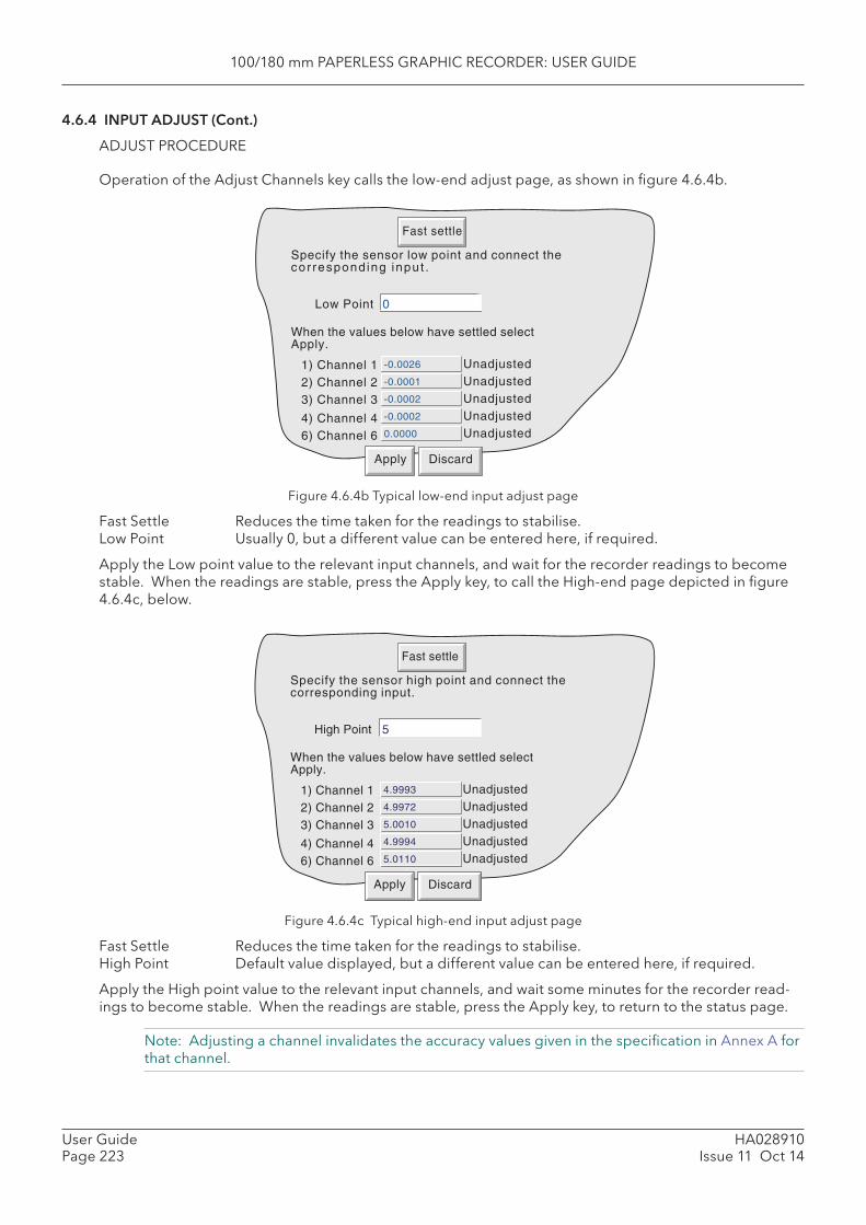
100/180 mm PAPERLESS GRAPHIC RECORDER: USER GUIDE
HA028910Issue 11 Oct 14
User GuidePage 223
4.6.4 INPUT ADJUST (Cont.)
ADJUST PROCEDURE
Operation of the Adjust Channels key calls the low-end adjust page, as shown in fi gure 4.6.4b.
Figure 4.6.4b Typical low-end input adjust page
Fast Settle Reduces the time taken for the readings to stabilise. Low Point Usually 0, but a different value can be entered here, if required.
Apply the Low point value to the relevant input channels, and wait for the recorder readings to become stable. When the readings are stable, press the Apply key, to call the High-end page depicted in fi gure 4.6.4c, below.
Figure 4.6.4c Typical high-end input adjust page
Fast Settle Reduces the time taken for the readings to stabilise. High Point Default value displayed, but a different value can be entered here, if required.
Apply the High point value to the relevant input channels, and wait some minutes for the recorder read-ings to become stable. When the readings are stable, press the Apply key, to return to the status page.
Note: Adjusting a channel invalidates the accuracy values given in the specifi cation in Annex A for that channel.
Specify the sensor low point and connect thecor respond ing input .
2) Channel 23) Channel 3
4) Channel 4 -0.0002
6) Channel 6
-0.0002
-0.0001
-0.0026
0.0000
1) Channel 1
Low Point 0
When the values below have settled selectApply.
UnadjustedUnadjustedUnadjustedUnadjustedUnadjusted
Apply Discard
Fast settle
Specify the sensor high point and connect thecorresponding input.
2) Channel 23) Channel 3
4) Channel 4 4.9994
6) Channel 6
5.0010
4.9972
4.9993
5.0110
1) Channel 1
High Point 5
When the values below have settled selectApply.
UnadjustedUnadjustedUnadjustedUnadjustedUnadjusted
Apply Discard
Fast settle
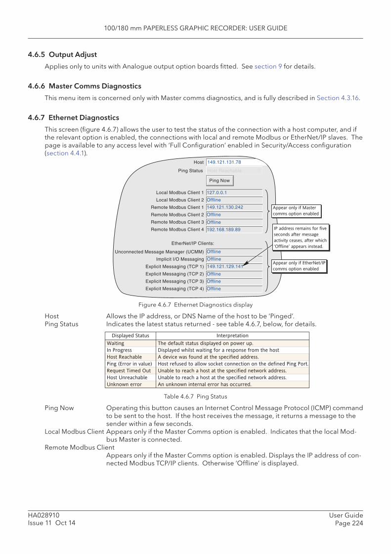
100/180 mm PAPERLESS GRAPHIC RECORDER: USER GUIDE
User GuidePage 224
HA028910Issue 11 Oct 14
4.6.5 Output Adjust
Applies only to units with Analogue output option boards fi tted. See section 9 for details.
4.6.6 Master Comms Diagnostics
This menu item is concerned only with Master comms diagnostics, and is fully described in Section 4.3.16.
4.6.7 Ethernet Diagnostics
This screen (fi gure 4.6.7) allows the user to test the status of the connection with a host computer, and if the relevant option is enabled, the connections with local and remote Modbus or EtherNet/IP slaves. The page is available to any access level with ‘Full Confi guration’ enabled in Security/Access confi guration (section 4.4.1).
Figure 4.6.7 Ethernet Diagnostics display
Host Allows the IP address, or DNS Name of the host to be ‘Pinged’. Ping Status Indicates the latest status returned - see table 4.6.7, below, for details.
Table 4.6.7 Ping Status
Ping Now Operating this button causes an Internet Control Message Protocol (ICMP) command to be sent to the host. If the host receives the message, it returns a message to the sender within a few seconds.
Local Modbus Client Appears only if the Master Comms option is enabled. Indicates that the local Mod-bus Master is connected.
Remote Modbus Client Appears only if the Master Comms option is enabled. Displays the IP address of con-nected Modbus TCP/IP clients. Otherwise ‘Offl ine’ is displayed.
Host
Ping Status
149.121.131.78
Host Reachable
Ping Now
Local Modbus Client 1
Local Modbus Client 2
Remote Modbus Client 1
Remote Modbus Client 2
Remote Modbus Client 3
Remote Modbus Client 4
127.0.0.1
Offline
149.121.130.242
Offline
Offline
192.168.189.89
Unconnected Message Manager (UCMM)
Implicit I/O Messaging
Explicit Messaging (TCP 1)
Explicit Messaging (TCP 2)
Explicit Messaging (TCP 3)
Explicit Messaging (TCP 4)
Offline
Offline
149.121.129.141
Offline
Offline
Offline
Appear only if Master
comms option enabled
Appear only if EtherNet/IP
comms option enabled
EtherNet/IP Clients:
IP address remains for five
seconds after message
activity ceases, after which
appears instead.
Waiting
In Progress
Host Reachable
Ping (Error in value)
Request Timed Out
Host Unreachable
Unknown error
The default status displayed on power up.
Displayed whilst waiting for a response from the host
A device was found at the specified address.
Host refused to allow socket connection on the defined Ping Port.
Unable to reach a host at the specified network address.
Unable to reach a host at the specified network address.
An unknown internal error has occurred.
Displayed Status Interpretation
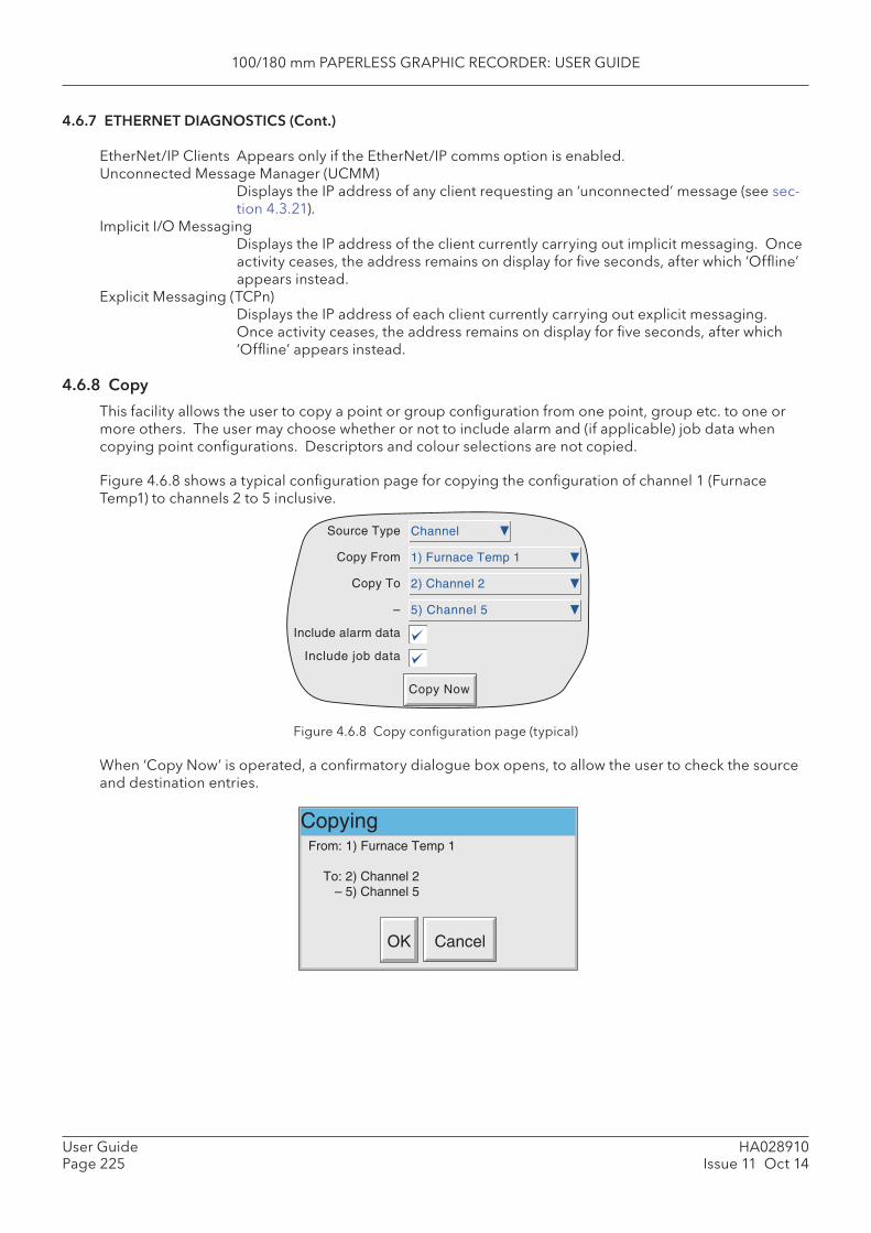
100/180 mm PAPERLESS GRAPHIC RECORDER: USER GUIDE
HA028910Issue 11 Oct 14
User GuidePage 225
4.6.7 ETHERNET DIAGNOSTICS (Cont.)
EtherNet/IP Clients Appears only if the EtherNet/IP comms option is enabled. Unconnected Message Manager ( UCMM)
Displays the IP address of any client requesting an ‘unconnected’ message (see sec-tion 4.3.21).
Implicit I/O MessagingDisplays the IP address of the client currently carrying out implicit messaging. Once activity ceases, the address remains on display for fi ve seconds, after which ‘Offl ine’ appears instead.
Explicit Messaging (TCPn)Displays the IP address of each client currently carrying out explicit messaging. Once activity ceases, the address remains on display for fi ve seconds, after which ‘Offl ine’ appears instead.
4.6.8 Copy
This facility allows the user to copy a point or group confi guration from one point, group etc. to one or more others. The user may choose whether or not to include alarm and (if applicable) job data when copying point confi gurations. Descriptors and colour selections are not copied.
Figure 4.6.8 shows a typical confi guration page for copying the confi guration of channel 1 (Furnace Temp1) to channels 2 to 5 inclusive.
Figure 4.6.8 Copy confi guration page (typical)
When ‘Copy Now’ is operated, a confi rmatory dialogue box opens, to allow the user to check the source and destination entries.
Copy Now
Source Type
Copy From
Copy To
–
Include alarm data
Include job data
Channel
1) Furnace Temp 1
2) Channel 2
5) Channel 5
CopyingFrom: 1) Furnace Temp 1
To: 2) Channel 2– 5) Channel 5
OK Cancel

100/180 mm PAPERLESS GRAPHIC RECORDER: USER GUIDE
User GuidePage 226
HA028910Issue 11 Oct 14
4.6.8 COPY (Cont.)
CONFIGURABLE PARAMETERS Source Type Picklist allows selection of Group, Channel, Event, Message, Maths Channel, Total-
iser, Counter, Timer, Output or Demand Write, as the type of source to be copied. Copy From Allows the user to select a specifi c point, group etc. to be copiedCopy To Allows the fi rst destination point to be selected, for the source to be copied to.– Allows the fi nal destination point to be selected for the source to be copied to. Include alarm data This fi eld appears only for source types which support alarms. If this box is ‘selected’,
then alarm data is included in the copy process. Include job data This fi eld appears only for source types which support jobs. If this box is ‘selected’,
then jobs data is included in the copy. For source types that support both alarms and jobs, it is not possible to include job data, without including alarm data as well.
Once the copy is complete, the user should enter the confi guration area of the items that have been cop-ied, and edit/apply the changes etc.
COPY RULES1. The fi rst channel on any input card may not be a digital input type.2. If a destination channel was a digital input, AND the source channel is an analogue input AND ‘in-
clude alarm data’ is not selected, the destination channel alarm settings will be set as: Enable = Off; Type = Absolute high; Threshold = 0.0; Dwell = 0.0.3. If a destination channel was an analogue input, AND the source channel is a digital input AND ‘in-
clude alarm data’ is not selected, the destination channel alarm settings will be set as: Enable = Off; Type = Digital; Threshold = Closed; Dwell = 0.0.4. Descriptors and Colours are never copied.
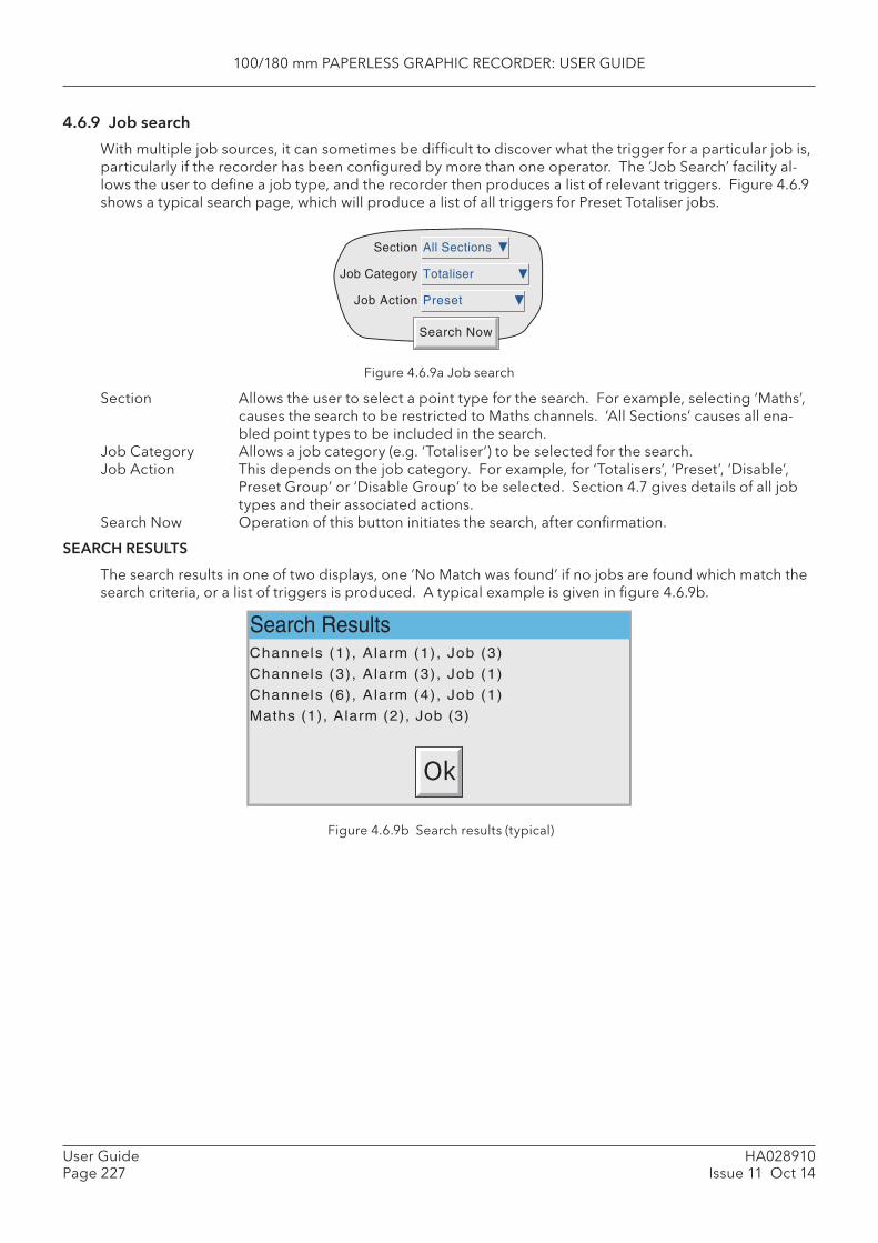
100/180 mm PAPERLESS GRAPHIC RECORDER: USER GUIDE
HA028910Issue 11 Oct 14
User GuidePage 227
4.6.9 Job search
With multiple job sources, it can sometimes be diffi cult to discover what the trigger for a particular job is, particularly if the recorder has been confi gured by more than one operator. The ‘Job Search’ facility al-lows the user to defi ne a job type, and the recorder then produces a list of relevant triggers. Figure 4.6.9 shows a typical search page, which will produce a list of all triggers for Preset Totaliser jobs.
Figure 4.6.9a Job search
Section Allows the user to select a point type for the search. For example, selecting ‘Maths’, causes the search to be restricted to Maths channels. ‘All Sections’ causes all ena-bled point types to be included in the search.
Job Category Allows a job category (e.g. ‘Totaliser’) to be selected for the search.Job Action This depends on the job category. For example, for ‘Totalisers’, ‘Preset’, ‘Disable’,
Preset Group’ or ‘Disable Group’ to be selected. Section 4.7 gives details of all job types and their associated actions.
Search Now Operation of this button initiates the search, after confi rmation.
SEARCH RESULTS
The search results in one of two displays, one ‘No Match was found’ if no jobs are found which match the search criteria, or a list of triggers is produced. A typical example is given in fi gure 4.6.9b.
Figure 4.6.9b Search results (typical)
Search Now
All Sections
Totaliser
Preset
Section
Job Category
Job Action
Search ResultsChannels (1) , Alarm (1), Job (3)
Channels (3) , Alarm (3), Job (1)
Channels (6) , Alarm (4), Job (1)
Maths (1), Alarm (2), Job (3)
Ok
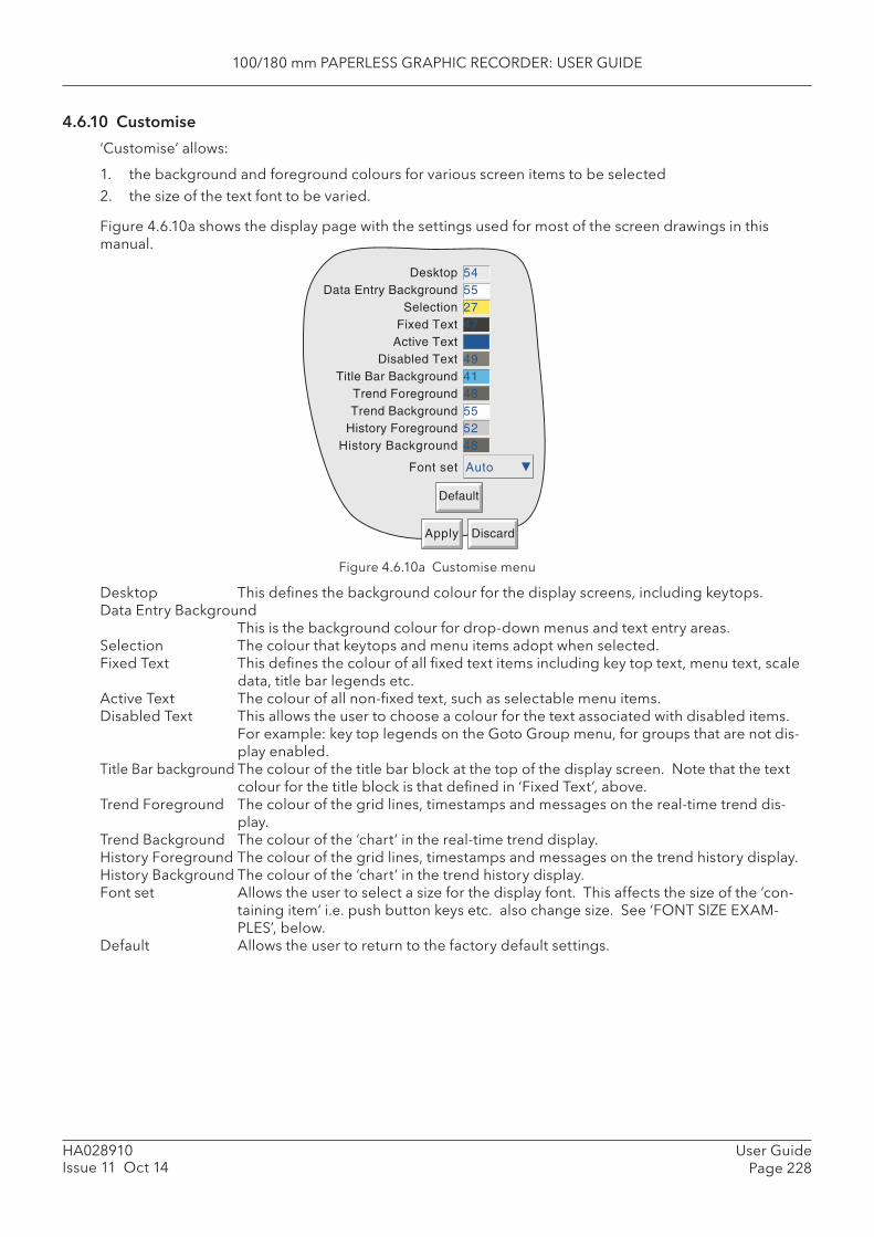
100/180 mm PAPERLESS GRAPHIC RECORDER: USER GUIDE
User GuidePage 228
HA028910Issue 11 Oct 14
4.6.10 Customise
‘Customise’ allows:
1. the background and foreground colours for various screen items to be selected2. the size of the text font to be varied.
Figure 4.6.10a shows the display page with the settings used for most of the screen drawings in this manual.
Figure 4.6.10a Customise menu
Desktop This defi nes the background colour for the display screens, including keytops. Data Entry Background
This is the background colour for drop-down menus and text entry areas. Selection The colour that keytops and menu items adopt when selected. Fixed Text This defi nes the colour of all fi xed text items including key top text, menu text, scale
data, title bar legends etc. Active Text The colour of all non-fi xed text, such as selectable menu items. Disabled Text This allows the user to choose a colour for the text associated with disabled items.
For example: key top legends on the Goto Group menu, for groups that are not dis-play enabled.
Title Bar background The colour of the title bar block at the top of the display screen. Note that the text colour for the title block is that defi ned in ‘Fixed Text’, above.
Trend Foreground The colour of the grid lines, timestamps and messages on the real-time trend dis-play.
Trend Background The colour of the ‘chart’ in the real-time trend display. History Foreground The colour of the grid lines, timestamps and messages on the trend history display.History Background The colour of the ‘chart’ in the trend history display. Font set Allows the user to select a size for the display font. This affects the size of the ‘con-
taining item’ i.e. push button keys etc. also change size. See ‘FONT SIZE EXAM-PLES’, below.
Default Allows the user to return to the factory default settings.
DesktopData Entry Background
SelectionFixed Text
Active TextDisabled Text
Title Bar BackgroundTrend ForegroundTrend Background
History ForegroundHistory Background
545527476494148555248
Font set Auto
Default
Apply Discard
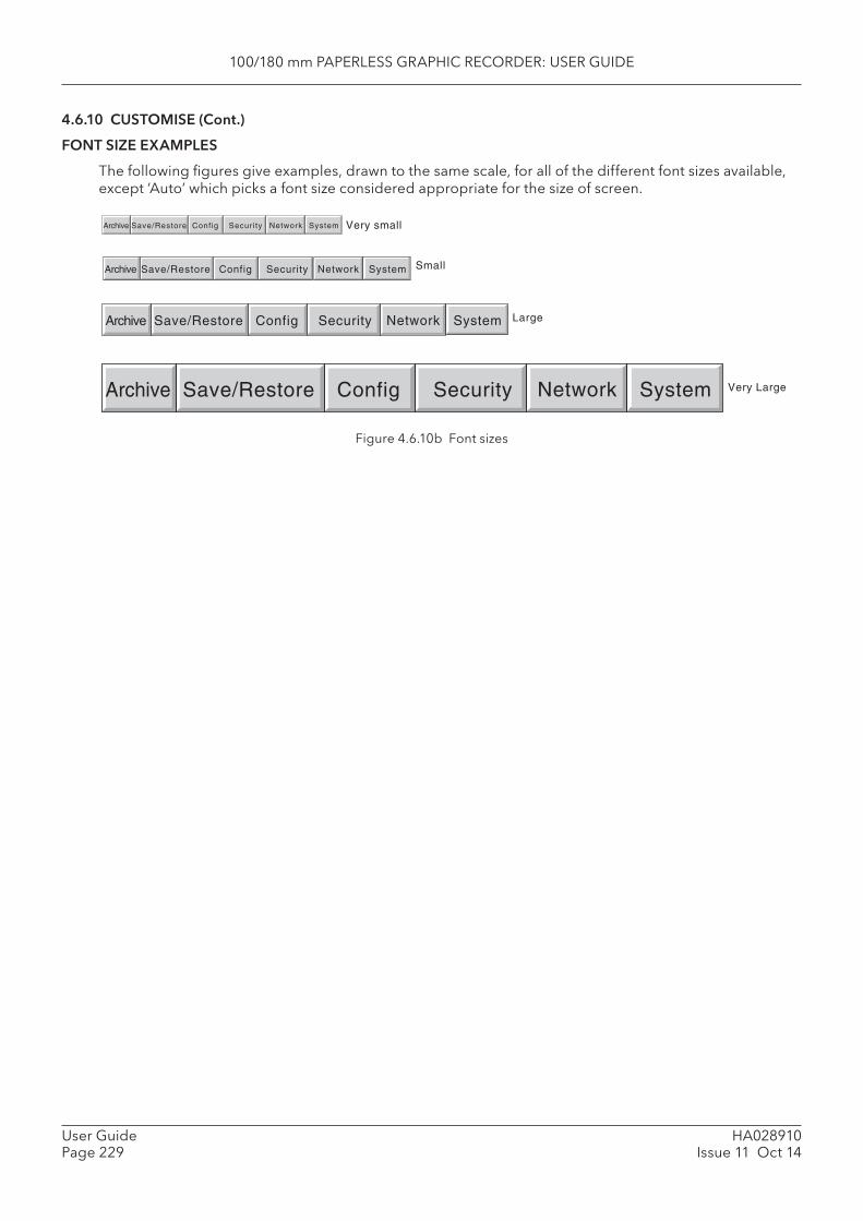
100/180 mm PAPERLESS GRAPHIC RECORDER: USER GUIDE
HA028910Issue 11 Oct 14
User GuidePage 229
4.6.10 CUSTOMISE (Cont.)
FONT SIZE EXAMPLES
The following fi gures give examples, drawn to the same scale, for all of the different font sizes available, except ‘Auto’ which picks a font size considered appropriate for the size of screen.
Figure 4.6.10b Font sizes
Archive Save/Restore Config Security Network System
Archive Save/Restore Config Security Network System
Archive Save/Restore Config Security Network System
Archive Save/Restore Config Security Network System
Very small
Small
Large
Very Large
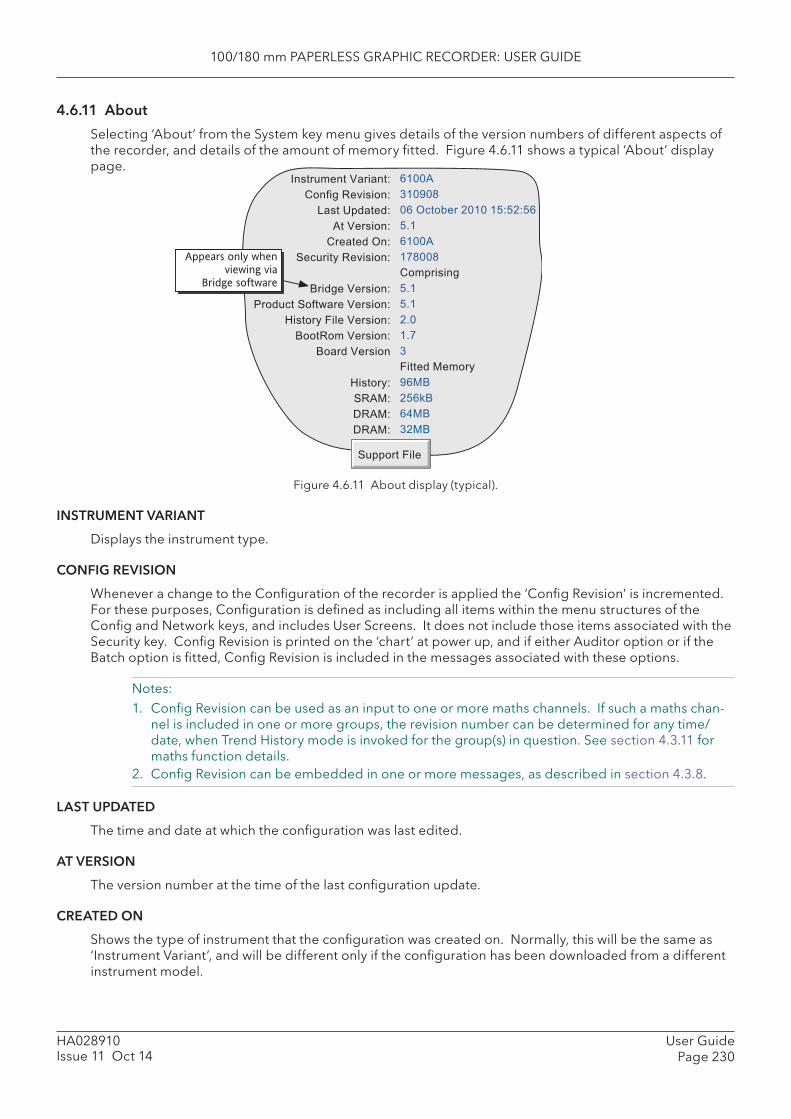
100/180 mm PAPERLESS GRAPHIC RECORDER: USER GUIDE
User GuidePage 230
HA028910Issue 11 Oct 14
4.6.11 About
Selecting ‘About’ from the System key menu gives details of the version numbers of different aspects of the recorder, and details of the amount of memory fi tted. Figure 4.6.11 shows a typical ‘About’ display page.
Figure 4.6.11 About display (typical).
INSTRUMENT VARIANT
Displays the instrument type.
CONFIG REVISION
Whenever a change to the Confi guration of the recorder is applied the ‘Confi g Revision’ is incremented. For these purposes, Confi guration is defi ned as including all items within the menu structures of the Confi g and Network keys, and includes User Screens. It does not include those items associated with the Security key. Confi g Revision is printed on the ‘chart’ at power up, and if either Auditor option or if the Batch option is fi tted, Confi g Revision is included in the messages associated with these options.
Notes:1. Confi g Revision can be used as an input to one or more maths channels. If such a maths chan-
nel is included in one or more groups, the revision number can be determined for any time/date, when Trend History mode is invoked for the group(s) in question. See section 4.3.11 for maths function details.
2. Confi g Revision can be embedded in one or more messages, as described in section 4.3.8.
LAST UPDATED
The time and date at which the confi guration was last edited.
AT VERSION
The version number at the time of the last confi guration update.
CREATED ON
Shows the type of instrument that the confi guration was created on. Normally, this will be the same as ‘Instrument Variant’, and will be different only if the confi guration has been downloaded from a different instrument model.
/� ���������������4�
"�5�����+� ��4�
*� ��1%���4�
)����� ��4�
"������3�4�
(����������+� ��4�
�
&�������� ��4�
0�����(5�6������� ��4�
7� ������������ ��4�
&������� ��4�
&������ ���
�
7� ���4�
(�)�4�
��)�4�
��)�4
���)�
���8���
� �3������!�����949!49 �
9:��
���)�
�#�����
"�%�� ����
9:��
9:��
!:��
�:#�
��
������������
8 �&�
!9 ;&�
2�&�
�!�&
(�%%�������
Appears only when
viewing via �
Bridge software

100/180 mm PAPERLESS GRAPHIC RECORDER: USER GUIDE
HA028910Issue 11 Oct 14
User GuidePage 231
4.6.11 ABOUT (Cont.)
SECURITY REVISION
Whenever a change is made to an item within the Security menus, the Security revision is incremented. Security Revision is printed on the ‘chart’ at power up, and if either of the Auditor options or if the Batch option is fi tted, Security Revision is included in the messages associated with these options. See notes 1 and 2, below.
Notes: 1 Security Revision can be used as an input to one or more maths channels. If such a maths chan-
nel is included in one or more groups, the revision number can be determined for any time/date, when Trend History mode is invoked for the group(s) in question. See section 4.3.11 for maths option details.
2. If ‘Centralised Security’ is enabled, the Security Revision is in a different format (e.g. 15.001) see section 4.4.2.
SUPPORT FILE
If the unit is not performing as it should (e.g. it resets itself unexpectedly), the Support File key allows the user to save ‘critical system fi les’ into a single fi le ( SupportInfo.uhq*), for despatch to the manufacturer for analysis. This fi le may be saved to the instrument’s Compact Flash or SD card or, using Bridge ‘Full’ software, to a remote PC. For security reasons, this fi le cannot be viewed by anyone other than the manu-facturer or his agents.
Once the save operation is complete, a ‘Support’ message appears on the screen giving details of where to send the fi le. More information is held in the fi le ‘SupportInfo.txt’ which is also saved to the disk. This fi le can be opened, and the information within it read, by inserting the disk into a PC, clicking on the fl oppy disk icon (A drive) in ‘My Computer’ and then double clicking on the fi le icon when it appears.
* ‘SupportInfo’ is the default name. This name may be edited by the user before saving to disk or pc. The .uhq suffi x is automatically appended to the new name.
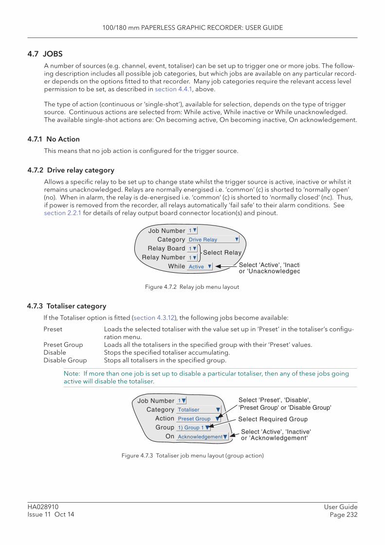
100/180 mm PAPERLESS GRAPHIC RECORDER: USER GUIDE
User GuidePage 232
HA028910Issue 11 Oct 14
4.7 JOBSA number of sources (e.g. channel, event, totaliser) can be set up to trigger one or more jobs. The follow-ing description includes all possible job categories, but which jobs are available on any particular record-er depends on the options fi tted to that recorder. Many job categories require the relevant access level permission to be set, as described in section 4.4.1, above.
The type of action (continuous or ‘single-shot’), available for selection, depends on the type of trigger source. Continuous actions are selected from: While active, While inactive or While unacknowledged. The available single-shot actions are: On becoming active, On becoming inactive, On acknowledgement.
4.7.1 No Action
This means that no job action is confi gured for the trigger source.
4.7.2 Drive relay category
Allows a specifi c relay to be set up to change state whilst the trigger source is active, inactive or whilst it remains unacknowledged. Relays are normally energised i.e. ‘common’ (c) is shorted to ‘normally open’ (no). When in alarm, the relay is de-energised i.e. ‘common’ (c) is shorted to ‘normally closed’ (nc). Thus, if power is removed from the recorder, all relays automatically ‘fail safe’ to their alarm conditions. See section 2.2.1 for details of relay output board connector location(s) and pinout.
Job Number
Relay BoardCategory
Relay NumberWhile
1
Drive Relay
Active
Select Relay
Select 'Active', 'Inactior 'Unacknowledged
1
1
Figure 4.7.2 Relay job menu layout
4.7.3 Totaliser category
If the Totaliser option is fi tted (section 4.3.12), the following jobs become available:
Preset Loads the selected totaliser with the value set up in ‘Preset’ in the totaliser’s confi gu-ration menu.
Preset Group Loads all the totalisers in the specifi ed group with their ‘Preset’ values. Disable Stops the specifi ed totaliser accumulating. Disable Group Stops all totalisers in the specifi ed group.
Note: If more than one job is set up to disable a particular totaliser, then any of these jobs going active will disable the totaliser.
Figure 4.7.3 Totaliser job menu layout (group action)
Job Number
ActionCategory
GroupOn
1) Group 1
1
Totaliser
Preset Group
Acknowledgement
Select 'Preset', 'Disable','Preset Group' or 'Disable Group'
Select Required Group
Select 'Active', 'Inactive'or 'Acknowledgement'

100/180 mm PAPERLESS GRAPHIC RECORDER: USER GUIDE
HA028910Issue 11 Oct 14
User GuidePage 233
4.7.4 Message category
One or more messages (section 4.3.8) can be directed to the display, to ‘All groups’ or to a ‘Specifi ed Group’. The messages must be contiguous - e.g. messages 2, 3 and 4 may be sent, but messages 1, 3 and 4 cannot be sent, without message 2 as well.
Figure 4.7.4 Message job menu layout
4.7.5 Maths category
If Maths channels (section 4.3.11) are enabled, the following jobs become available to applicable func-tions:
Reset Sets the selected maths channel value to zero. Disable Stops historical functions such as Fvalue, Stopwatch and Rolling Average from accu-
mulating further values. When the function is subsequently re-enabled, the function re-starts from its pre-disabled value. ‘Disable’ has no effect on other functions.
Switch to B Causes the relevant maths channel to copy source B instead of its normal source A - see section 4.3.11 for further details.
Trigger Used to initiate a ‘Sample and hold’ function - see section 4.3.11 for further details.
Figure 4.7.5 Maths job menu layout
Select 'Display', 'All Groups', or 'Specified Group'
Job Number
Send Message(s) toCategory
First MessageLast Message
Group Select Required Group(only if 'Specified Group' previously selected)
Select range of messages to be output.
On Select 'Active', 'Inactive' or 'Acknowledgement'
1) Message 1
1
Message
Specified Group
1) Group 1
1) Message 1
Active
Job Number
ActionCategory
MathOn
Math 1
1
Math
Reset
Active
Select 'Reset', 'Disable''Switch to B' or 'Trigger'
Select Required Maths channel
Select 'Active', 'Inactive',or 'Acknowledgement'
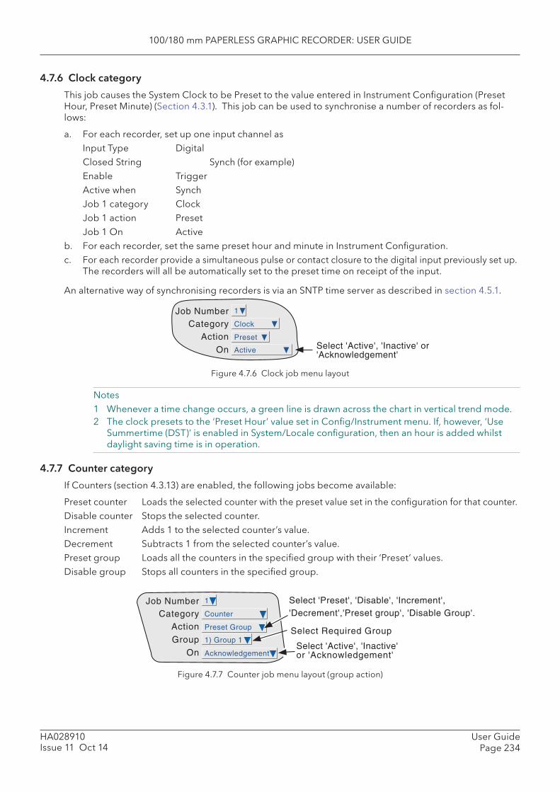
100/180 mm PAPERLESS GRAPHIC RECORDER: USER GUIDE
User GuidePage 234
HA028910Issue 11 Oct 14
4.7.6 Clock category
This job causes the System Clock to be Preset to the value entered in Instrument Confi guration (Preset Hour, Preset Minute) (Section 4.3.1). This job can be used to synchronise a number of recorders as fol-lows:
a. For each recorder, set up one input channel as Input Type Digital Closed String Synch (for example) Enable Trigger Active when Synch Job 1 category Clock Job 1 action Preset Job 1 On Activeb. For each recorder, set the same preset hour and minute in Instrument Confi guration.c. For each recorder provide a simultaneous pulse or contact closure to the digital input previously set up.
The recorders will all be automatically set to the preset time on receipt of the input.
An alternative way of synchronising recorders is via an SNTP time server as described in section 4.5.1.
Job Number
ActionCategory
On Active
1
Clock
PresetSelect 'Active', 'Inactive' or'Acknowledgement'
Figure 4.7.6 Clock job menu layout
Notes1 Whenever a time change occurs, a green line is drawn across the chart in vertical trend mode.2 The clock presets to the ‘Preset Hour’ value set in Confi g/Instrument menu. If, however, ‘Use
Summertime (DST)’ is enabled in System/Locale confi guration, then an hour is added whilst daylight saving time is in operation.
4.7.7 Counter category
If Counters (section 4.3.13) are enabled, the following jobs become available:
Preset counter Loads the selected counter with the preset value set in the confi guration for that counter. Disable counter Stops the selected counter. Increment Adds 1 to the selected counter’s value. Decrement Subtracts 1 from the selected counter’s value. Preset group Loads all the counters in the specifi ed group with their ‘Preset’ values. Disable group Stops all counters in the specifi ed group.
Figure 4.7.7 Counter job menu layout (group action)
Select 'Preset', 'Disable', 'Increment','Decrement','Preset group', 'Disable Group'.
Job Number
ActionCategory
GroupOn
1) Group 1
1
Counter
Preset Group
Acknowledgement
Select Required Group
Select 'Active', 'Inactive'or 'Acknowledgement'
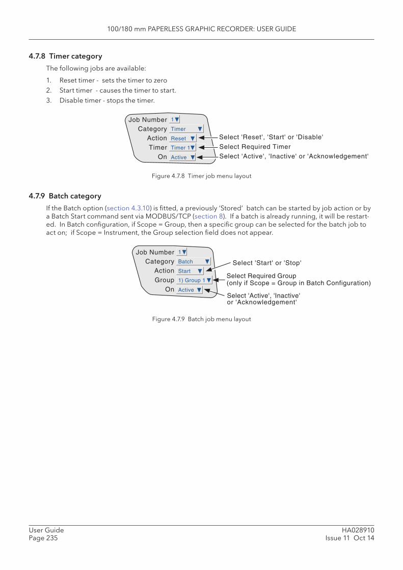
100/180 mm PAPERLESS GRAPHIC RECORDER: USER GUIDE
HA028910Issue 11 Oct 14
User GuidePage 235
4.7.8 Timer category
The following jobs are available:
1. Reset timer - sets the timer to zero2. Start timer - causes the timer to start. 3. Disable timer - stops the timer.
Figure 4.7.8 Timer job menu layout
4.7.9 Batch category
If the Batch option (section 4.3.10) is fi tted, a previously ‘Stored’ batch can be started by job action or by a Batch Start command sent via MODBUS/TCP (section 8). If a batch is already running, it will be restart-ed. In Batch confi guration, if Scope = Group, then a specifi c group can be selected for the batch job to act on; if Scope = Instrument, the Group selection fi eld does not appear.
Figure 4.7.9 Batch job menu layout
Job Number
ActionCategory
TimerOn
Timer 1
1
Timer
Reset
Active
Select 'Reset', 'Start' or 'Disable'
Select Required Timer
Select 'Active', 'Inactive' or 'Acknowledgement'
Job Number
ActionCategory
GroupOn
1) Group 1
1
Batch
Start
Active
Select 'Start' or 'Stop'
Select Required Group(only if Scope = Group in Batch Configuration)
Select 'Active', 'Inactive'or 'Acknowledgement'
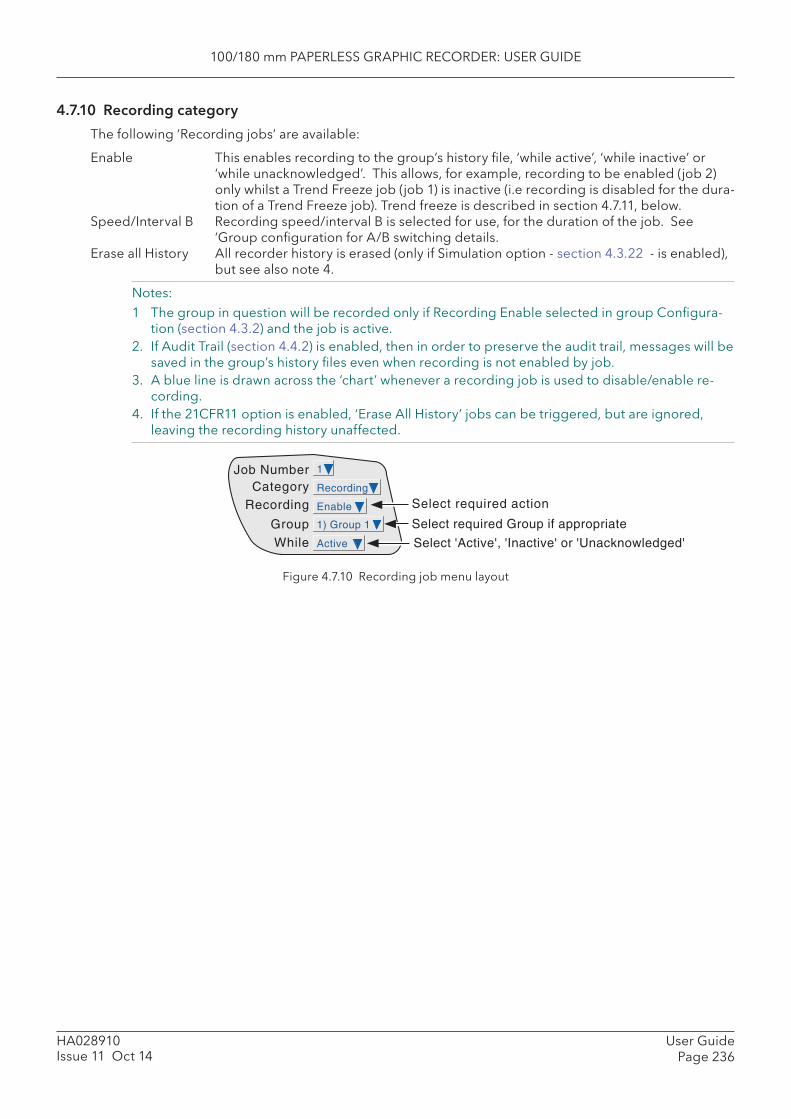
100/180 mm PAPERLESS GRAPHIC RECORDER: USER GUIDE
User GuidePage 236
HA028910Issue 11 Oct 14
4.7.10 Recording category
The following ‘Recording jobs’ are available:
Enable This enables recording to the group’s history fi le, ‘while active’, ‘while inactive’ or ‘while unacknowledged’. This allows, for example, recording to be enabled (job 2) only whilst a Trend Freeze job (job 1) is inactive (i.e recording is disabled for the dura-tion of a Trend Freeze job). Trend freeze is described in section 4.7.11, below.
Speed/Interval B Recording speed/interval B is selected for use, for the duration of the job. See ‘Group confi guration for A/B switching details.
Erase all History All recorder history is erased (only if Simulation option - section 4.3.22 - is enabled), but see also note 4.
Notes:1 The group in question will be recorded only if Recording Enable selected in group Confi gura-
tion (section 4.3.2) and the job is active. 2. If Audit Trail (section 4.4.2) is enabled, then in order to preserve the audit trail, messages will be
saved in the group’s history fi les even when recording is not enabled by job.3. A blue line is drawn across the ‘chart’ whenever a recording job is used to disable/enable re-
cording.4. If the 21CFR11 option is enabled, ‘Erase All History’ jobs can be triggered, but are ignored,
leaving the recording history unaffected.
Job Number
RecordingCategory
GroupWhile
1) Group 1
1
Recording
Enable
Active
Select required action
Select required Group if appropriate
Select 'Active', 'Inactive' or 'Unacknowledged'
Figure 4.7.10 Recording job menu layout
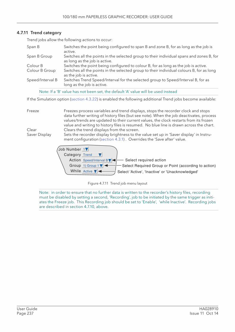
100/180 mm PAPERLESS GRAPHIC RECORDER: USER GUIDE
HA028910Issue 11 Oct 14
User GuidePage 237
4.7.11 Trend category
Trend jobs allow the following actions to occur:
Span B Switches the point being confi gured to span B and zone B, for as long as the job is active.
Span B Group Switches all the points in the selected group to their individual spans and zones B, for as long as the job is active.
Colour B Switches the point being confi gured to colour B, for as long as the job is active. Colour B Group Switches all the points in the selected group to their individual colours B, for as long
as the job is active. Speed /Interval B Switches Trend Speed/Interval for the selected group to Speed/Interval B, for as
long as the job is active.
Note: If a ‘B’ value has not been set, the default ‘A’ value will be used instead
If the Simulation option (section 4.3.22) is enabled the following additional Trend jobs become available:
Freeze Freezes process variables and trend displays, stops the recorder clock and stops data further writing of history fi les (but see note). When the job deactivates, process values/trends are updated to their current values, the clock restarts from its frozen value and writing to history fi les is resumed. No blue line is drawn across the chart.
Clear Clears the trend displays from the screen. Saver Display Sets the recorder display brightness to the value set up in ‘Saver display’ in Instru-
ment confi guration (section 4.3.1) . Overrides the ‘Save after’ value.
Figure 4.7.11 Trend job menu layout
Note: in order to ensure that no further data is written to the recorder’s history fi les, recording must be disabled by setting a second, ‘Recording’, job to be initiated by the same trigger as initi-ates the Freeze job. This Recording job should be set to ‘Enable’, ‘while Inactive’. Recording jobs are described in section 4.7.10, above.
Job Number
ActionCategory
GroupWhile
1) Group 1
1
Trend
Speed/Interval B
Active
Select required action
Select Required Group or Point (according to action)
Select 'Active', 'Inactive' or 'Unacknowledged'
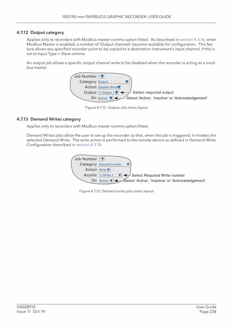
100/180 mm PAPERLESS GRAPHIC RECORDER: USER GUIDE
User GuidePage 238
HA028910Issue 11 Oct 14
4.7.12 Output category
Applies only to recorders with Modbus master comms option fi tted. As described in section 4.3.16, when Modbus Master is enabled, a number of ‘Output channels’ become available for confi guration. This fea-ture allows any specifi ed recorder point to be copied to a destination instrument’s input channel, if this is set to Input Type = Slave comms.
An output job allows a specifi c output channel write to be disabled when the recorder is acting as a mod-bus master.
Figure 4.7.12 Output Job menu layout
4.7.13 Demand Writes category
Applies only to recorders with Modbus master comms option fi tted.
Demand Writes jobs allow the user to set up the recorder so that, when the job is triggered, it initiates the selected Demand Write. The write action is performed to the remote device as defi ned in Demand Write Confi guration described in section 4.3.18.
Figure 4.7.13 Demand write jobs menu layout
Job Number
ActionCategory
OutputOn
1
Output
Disable Write
Active
1) Output 1
Select 'Active', 'Inactive' or 'Acknowledgement'
Select required output
Job Number
ActionCategory
AcyclicOn
1
Demand writes
Write
Active
1) Write 1 Select Required Write numberSelect 'Active', 'Inactive' or 'Acknowledgement'
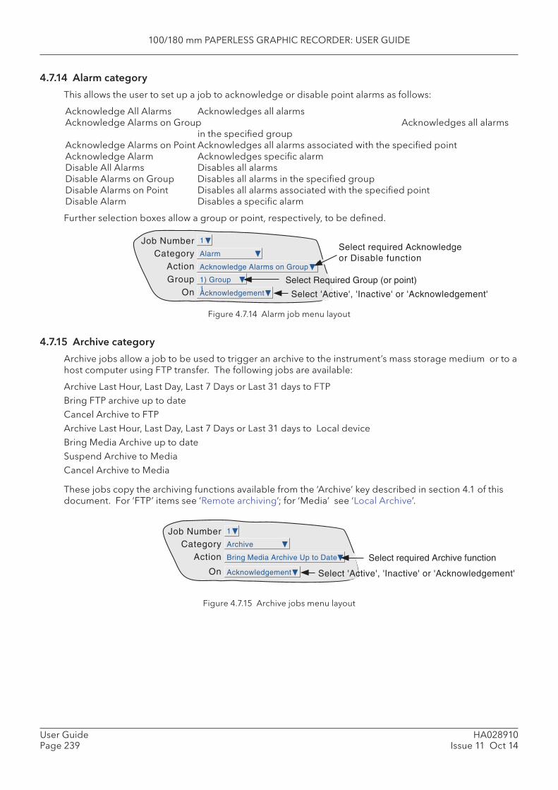
100/180 mm PAPERLESS GRAPHIC RECORDER: USER GUIDE
HA028910Issue 11 Oct 14
User GuidePage 239
4.7.14 Alarm category
This allows the user to set up a job to acknowledge or disable point alarms as follows:
Acknowledge All Alarms Acknowledges all alarmsAcknowledge Alarms on Group Acknowledges all alarms
in the specifi ed groupAcknowledge Alarms on Point Acknowledges all alarms associated with the specifi ed point Acknowledge Alarm Acknowledges specifi c alarm Disable All Alarms Disables all alarmsDisable Alarms on Group Disables all alarms in the specifi ed groupDisable Alarms on Point Disables all alarms associated with the specifi ed pointDisable Alarm Disables a specifi c alarm
Further selection boxes allow a group or point, respectively, to be defi ned.
Job Number
ActionCategory
GroupOn
1) Group1
1
Alarm
Acknowledge Alarms on Group
Acknowledgement
Select required Acknowledgeor Disable function
Select Required Group (or point)
Select 'Active', 'Inactive' or 'Acknowledgement'
Job Number
ActionCategory
On
1
Archive
Bring Media Archive Up to Date
Acknowledgement
Select required Archive function
Select 'Active', 'Inactive' or 'Acknowledgement'
Figure 4.7.14 Alarm job menu layout
4.7.15 Archive category
Archive jobs allow a job to be used to trigger an archive to the instrument’s mass storage medium or to a host computer using FTP transfer. The following jobs are available:
Archive Last Hour, Last Day, Last 7 Days or Last 31 days to FTP Bring FTP archive up to date Cancel Archive to FTPArchive Last Hour, Last Day, Last 7 Days or Last 31 days to Local deviceBring Media Archive up to date Suspend Archive to MediaCancel Archive to Media
These jobs copy the archiving functions available from the ‘Archive’ key described in section 4.1 of this document. For ‘FTP’ items see ‘Remote archiving’; for ‘Media’ see ‘Local Archive’.
Figure 4.7.15 Archive jobs menu layout
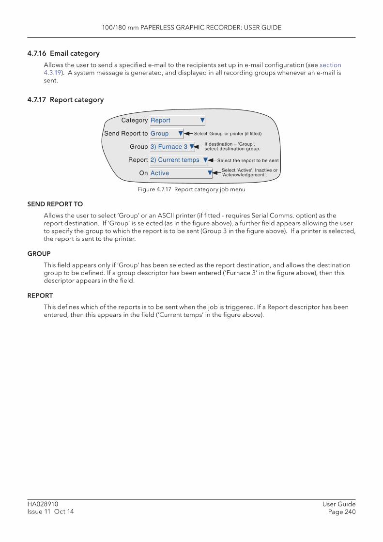
100/180 mm PAPERLESS GRAPHIC RECORDER: USER GUIDE
User GuidePage 240
HA028910Issue 11 Oct 14
4.7.16 Email category
Allows the user to send a specifi ed e-mail to the recipients set up in e-mail confi guration (see section 4.3.19). A system message is generated, and displayed in all recording groups whenever an e-mail is sent.
4.7.17 Report category
Figure 4.7.17 Report category job menu
SEND REPORT TO
Allows the user to select ‘Group’ or an ASCII printer (if fi tted - requires Serial Comms. option) as the report destination. If ‘Group’ is selected (as in the fi gure above), a further fi eld appears allowing the user to specify the group to which the report is to be sent (Group 3 in the fi gure above). If a printer is selected, the report is sent to the printer.
GROUP
This fi eld appears only if ‘Group’ has been selected as the report destination, and allows the destination group to be defi ned. If a group descriptor has been entered (‘Furnace 3’ in the fi gure above), then this descriptor appears in the fi eld.
REPORT
This defi nes which of the reports is to be sent when the job is triggered. If a Report descriptor has been entered, then this appears in the fi eld (‘Current temps’ in the fi gure above).
Report
Group
3) Furnace 3
2) Current temps
Active
Category
Send Report to
Group
Report
On
Select 'Group' or printer (if fitted)
If destination = 'Group',select destination group.
Select the report to be sent
Select 'Active', Inactive or'Acknowledgement'.

100/180 mm PAPERLESS GRAPHIC RECORDER: USER GUIDE
HA028910Issue 11 Oct 14
User GuidePage 241
5 FILEFigure 5, below, gives an overview of the File Menus. The area is entered by touching the ‘File’ key of the root menu, and can be used to display the contents of directories stored both in the user area of fl ash memory and on any bulk storage device inserted or connected.
The fi rst display page shows the ‘volume’ or ‘device’ names associated with the various areas of memory available to the user. If one of these volume names is selected (touched), and the ‘open-folder’ key* op-erated, the contents of the selected volume is displayed. This would typically consist of a list of folders. Similarly, if a folder name is selected and the ‘open folder’ key* is touched, the contents of the folder is displayed and so on.
To return to higher levels, the ‘close-folder’ key* is used.
The path name of the current window is shown at the top of the window.
*Note: The open-folder and close-folder key functions are the same as the down arrow and up arrow key functions respectively.
5.1 FILER OPTION MENU KEYSThese keys appear in a pop-up menu when the option key is pressed. This menu appears only when an actual fi le has been selected (i.e. it does not appear if a directory (folder) or volume is selected.) Cut and paste functions are available only to users with the relevant access permissions (section 4.4).
Cut Removes a fi le from the list, ready for ‘pasting’ to another destination. Copy Copies a fi le from the list, ready for ‘pasting’ to another destination. Delete Removes a fi le from the memory. New Allows a new directory (folder) to be created Paste Places a ‘cut’ or ‘copy’ fi le into the new destination. Refresh Refreshes the display.
A key’s legend is hidden* if at any time its function is not applicable.
* i.e. displayed in the colour selected for ‘Disabled Text’ in the System key ’Customise’ menu.
5.2 THE HIDE KEYThe Hide key at the top right corner of the display screen is used to hide (show) Type, Date and Bytes information, allowing the full fi lename text string to appear.
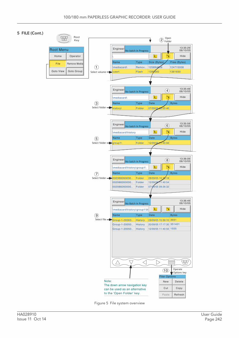
100/180 mm PAPERLESS GRAPHIC RECORDER: USER GUIDE
User GuidePage 242
HA028910Issue 11 Oct 14
5 FILE (Cont.)
Name Type Date Bytes
002088260000.. Folder 28/09/05 15:39:18
002088260000.. Folder 12/09/05 11:40:54
002088260000.. Folder 07/09/05 09:26:32
Engineer 13:36:0906/10/05
Hide
No batch In Progress
\mediacard\history\group1\
Select folder
Engineer 13:35:4906/10/05
Hide
No batch In Progress
\mediacard\
Name Type Date Bytes
history\ Folder 07/09/05 09:25:46
Engineer 13:35:2906/10/05
Hide
No batch In Progress
\
Name Type Size (Bytes) Free (Bytes)
\mediacard\ Remov.. 125894656 124715008
\user\ Flash 1390592 1361920
Engineer 13:35:5906/10/05
Hide
No batch In Progress
\mediacard\history
Name Type Date Bytes
group1\ Folder 12/09/05 11:40:56
Select volume
Select folder
Open
Folder
RootKey
Home Operator
File Remove Media
Goto View Goto Group
Root Menu
Filer Options
New Delete
Cut Copy
Paste Refresh
Engineer 13:36:4906/10/05No Batch In Progress
\mediacard\history\group1\000
Select folder
Name Type Date Bytes
Group-1-20050.. History 28/09/05 15:39:10
Hide
1
3931
Group-1-20050.. History 20/09/05 17:17:30 351401
Group-1-20050.. History 12/09/05 11:40:50 1555
2
3
5
4
6
8
7
Select file
9
Operate
Options key10
Note:The down arrow navigation keycan be used as an alternativeto the 'Open Folder' key.
Figure 5 File system overview
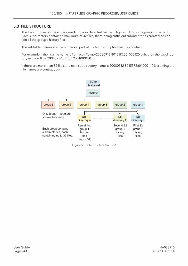
100/180 mm PAPERLESS GRAPHIC RECORDER: USER GUIDE
HA028910Issue 11 Oct 14
User GuidePage 243
5.3 FILE STRUCTUREThe fi le structure on the archive medium, is as depicted below in fi gure 5.3 for a six-group instrument. Each subdirectory contains a maximum of 32 fi les, there being suffi cient subdirectories created, to con-tain all the group’s history fi les.
The subfolder names are the numerical part of the fi rst history fi le that they contain.
For example if the fi rst fi le name is Furnace1 Temp~20080912 80155F2601000120.uhh, then the subdirec-tory name will be 20080912 80155F2601000120.
If there are more than 32 fi les, the next subdirectory name is 20080912 80155F2601000140 (assuming the fi le names are contiguous).
Figure 5.3 File structure (archive)
SD orFlash card
history\
group 4 group 3group 6 group 5 group 2 group 1
First 32group 1history
files
sub-directory 1
sub-directory n
sub-directory 2
Second 32group 1history
files
Remaininggroup 1history
files(max = 32)
Only group 1 structureshown, for clarity.
Each group containssubdirectories, eachcontaining up to 32 files.

100/180 mm PAPERLESS GRAPHIC RECORDER: USER GUIDE
HA028910Issue 11 Oct 14
User GuidePage 244
6 BRIDGE (REMOTE VIEWER)
6.1 INTRODUCTION This feature comes in two levels, called ‘Full’ (option) and ‘Lite’ (supplied as standard).
The ‘Full’ option allows full operation and confi guration of the recorder, simultaneously, from up to ten PCs which meet or exceed the minimum requirements listed below. When a change is being made to the confi guration of the recorder by one Bridge user (‘client’), the message:
Feature LockedAnother client (IP ADDRESS) has locked this feature. Wait for lock to be released and try again
appears on the screen of any other user who attempts to change the confi guration. When changes are complete, the message:
Feature changed Synchronising data
appears on the screens of all clients (except that of the one making the change).
Bridge ‘Lite’ allows the user to view recorder standard screens, dynamically, on-line, from up to 10 PCs which meet or exceed the minimum requirements listed below.
The software is supplied on a CD ROM, which also includes PC Review, PC Confi guration and Acrobat reader software and various manuals relevant to the recorder.
The Bridge software is suitable for any physical hardware confi gurations, some common examples being:
1. A single PC connected directly to a recorder.2. Multiple PCs connected via a network to one or more recorders. (Each recorder can be accessed, si-
multaneously, by a maximum of 10 PCs, but one PC can look at only ‘N’ recorders where ‘N’ depends on how much memory is available at the PC. For example, a minimum specifi cation computer (sec-tion 6.1.1) running Windows NT can ‘look at’ up to three recorders simultaneously.
3. A single PC connected via a telephone line to a remote recorder.
This manual does not describe network setup in detail, as each network is different. In most cases, the help of the network administrator or supervisor will be required, for example, in the allocation of valid addresses and passwords.
Notes:1 When logging in via ‘Bridge’, only users with ‘Connect from Remote’ enabled appear in the user
list. See section 4.4.1 for details.2 Full Bridge requires some small amount of space on the PC disk. The message ‘There appears
to be no free disk space on the client. Create some space and run again.’ appears if there is insuffi cient space.
3. If an attempt is made to establish more than one Full Bridge connection between a PC and an instrument, the message “ You are already running a Full Bridge session with this instrument. The new session will run as Bridge Lite.” appears.
4. If an attempt is made to establish a Full Bridge connection using the ‘anonymous’ user name, the following message appears: ‘You are authenticating Full Bridge using the “anonymous” user name. This provides guest read only access. To establish Full Bridge connection you must use a different user name. Please change and try again.’
5. The maximum number of Bridge sessions that can be run simultaneously on one recorder is 10.

100/180 mm PAPERLESS GRAPHIC RECORDER: USER GUIDE
HA028910Issue 11 Oct 14
User GuidePage 245
6.1.1 Minimum PC requirements
1. P90 running Windows NT/2000/XP Home/XP Pro/Server 2003.2. 32MB RAM3. 50MB free hard disk space4. Graphics drive capable of displaying > 256 colours (recommended)5. Sound card required for audible alarms feature (section 6.5)
SUPPORTED PDA CONFIGURATION
PDA not supported this issue of software
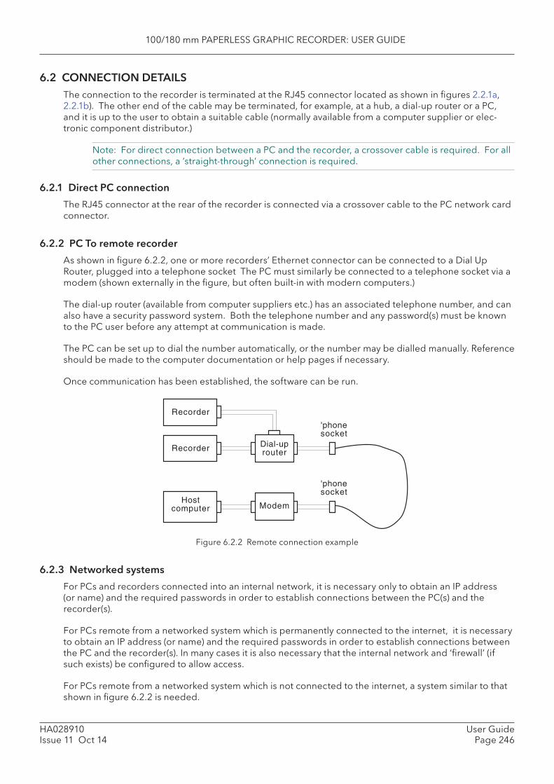
100/180 mm PAPERLESS GRAPHIC RECORDER: USER GUIDE
HA028910Issue 11 Oct 14
User GuidePage 246
6.2 CONNECTION DETAILSThe connection to the recorder is terminated at the RJ45 connector located as shown in fi gures 2.2.1a, 2.2.1b). The other end of the cable may be terminated, for example, at a hub, a dial-up router or a PC, and it is up to the user to obtain a suitable cable (normally available from a computer supplier or elec-tronic component distributor.)
Note: For direct connection between a PC and the recorder, a crossover cable is required. For all other connections, a ‘straight-through’ connection is required.
6.2.1 Direct PC connection
The RJ45 connector at the rear of the recorder is connected via a crossover cable to the PC network card connector.
6.2.2 PC To remote recorder
As shown in fi gure 6.2.2, one or more recorders’ Ethernet connector can be connected to a Dial Up Router, plugged into a telephone socket The PC must similarly be connected to a telephone socket via a modem (shown externally in the fi gure, but often built-in with modern computers.)
The dial-up router (available from computer suppliers etc.) has an associated telephone number, and can also have a security password system. Both the telephone number and any password(s) must be known to the PC user before any attempt at communication is made.
The PC can be set up to dial the number automatically, or the number may be dialled manually. Reference should be made to the computer documentation or help pages if necessary.
Once communication has been established, the software can be run.
Figure 6.2.2 Remote connection example
6.2.3 Networked systems
For PCs and recorders connected into an internal network, it is necessary only to obtain an IP address (or name) and the required passwords in order to establish connections between the PC(s) and the recorder(s).
For PCs remote from a networked system which is permanently connected to the internet, it is necessary to obtain an IP address (or name) and the required passwords in order to establish connections between the PC and the recorder(s). In many cases it is also necessary that the internal network and ‘fi rewall’ (if such exists) be confi gured to allow access.
For PCs remote from a networked system which is not connected to the internet, a system similar to that shown in fi gure 6.2.2 is needed.
Recorder Dial-uprouter
'phonesocket
Hostcomputer Modem
'phonesocket
Recorder
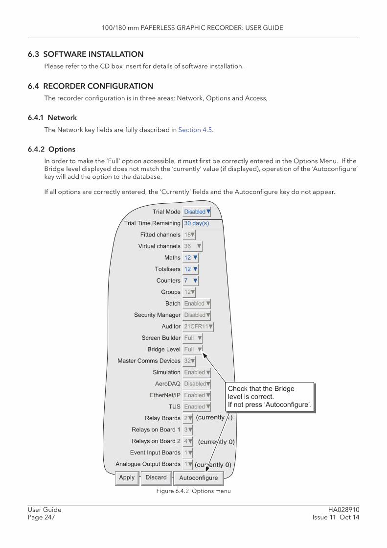
100/180 mm PAPERLESS GRAPHIC RECORDER: USER GUIDE
HA028910Issue 11 Oct 14
User GuidePage 247
6.3 SOFTWARE INSTALLATIONPlease refer to the CD box insert for details of software installation.
6.4 RECORDER CONFIGURATIONThe recorder confi guration is in three areas: Network, Options and Access,
6.4.1 Network
The Network key fi elds are fully described in Section 4.5.
6.4.2 Options
In order to make the ‘Full’ option accessible, it must fi rst be correctly entered in the Options Menu. If the Bridge level displayed does not match the ‘currently’ value (if displayed), operation of the ‘Autoconfi gure’ key will add the option to the database.
If all options are correctly entered, the ‘Currently’ fi elds and the Autoconfi gure key do not appear.
Figure 6.4.2 Options menu
�������� �� �����
�������������������� ������ ��
������������� ���
��������������� � �
���� �!�
����� �� �!�
"����� #�
$��% �!�
&���� '������
(��������������� �� �����
)���� !�"�����
(������&����� �����
&�����*�+�� �����
�� ����"�� ���+��� �!�
(�������� '������
)���), �� �����
'����-��./0 '������
�1( '������
������&�� !�
����� ���&���� ��
����� ���&���! 2�
'+����/�%���&�� ��
)�������3��%���&�� �
(currently 1)
(currently 0)
(currently 0)
Apply Discard Autoconfigure
"���;����������&��������+���� �������:��
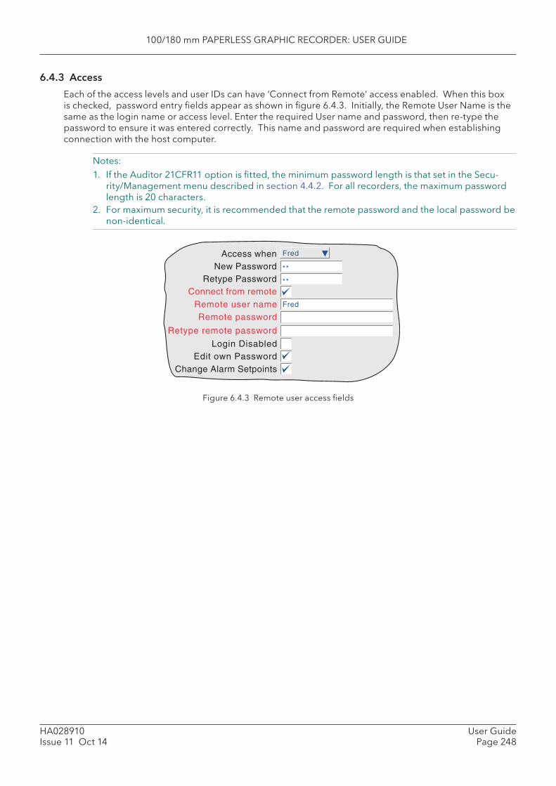
100/180 mm PAPERLESS GRAPHIC RECORDER: USER GUIDE
HA028910Issue 11 Oct 14
User GuidePage 248
6.4.3 Access
Each of the access levels and user IDs can have ‘Connect from Remote’ access enabled. When this box is checked, password entry fi elds appear as shown in fi gure 6.4.3. Initially, the Remote User Name is the same as the login name or access level. Enter the required User name and password, then re-type the password to ensure it was entered correctly. This name and password are required when establishing connection with the host computer.
Notes:1. If the Auditor 21CFR11 option is fi tted, the minimum password length is that set in the Secu-
rity/Management menu described in section 4.4.2. For all recorders, the maximum password length is 20 characters.
2. For maximum security, it is recommended that the remote password and the local password be non-identical.
Figure 6.4.3 Remote user access fi elds
FredAccess whenNew Password
Retype PasswordConnect from remote
Login Disabled
Change Alarm SetpointsEdit own Password
Remote user name Fred
Remote password
**
**
Retype remote password
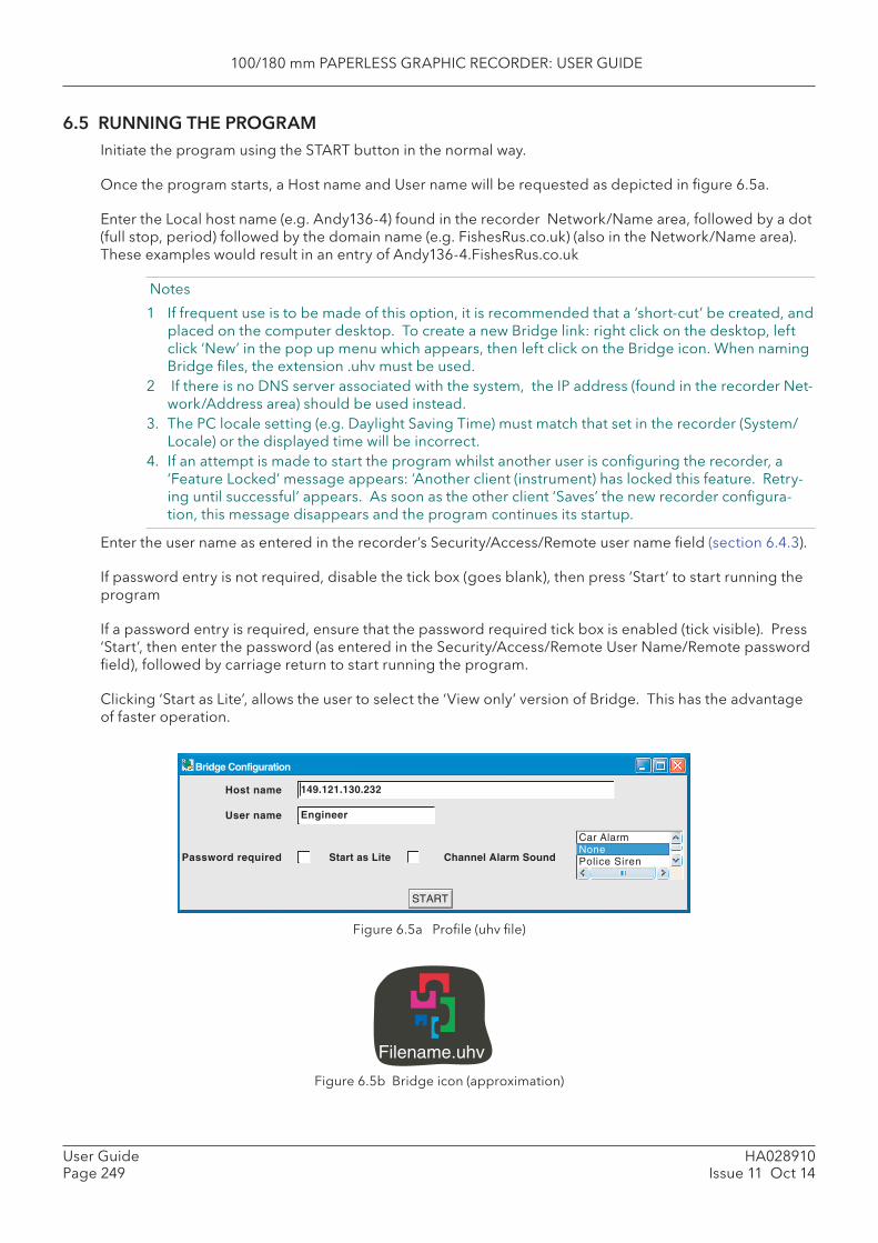
100/180 mm PAPERLESS GRAPHIC RECORDER: USER GUIDE
HA028910Issue 11 Oct 14
User GuidePage 249
6.5 RUNNING THE PROGRAMInitiate the program using the START button in the normal way.
Once the program starts, a Host name and User name will be requested as depicted in fi gure 6.5a.
Enter the Local host name (e.g. Andy136-4) found in the recorder Network/Name area, followed by a dot (full stop, period) followed by the domain name (e.g. FishesRus.co.uk) (also in the Network/Name area). These examples would result in an entry of Andy136-4.FishesRus.co.uk
Notes
1 If frequent use is to be made of this option, it is recommended that a ‘short-cut’ be created, and placed on the computer desktop. To create a new Bridge link: right click on the desktop, left click ‘New’ in the pop up menu which appears, then left click on the Bridge icon. When naming Bridge fi les, the extension .uhv must be used.
2 If there is no DNS server associated with the system, the IP address (found in the recorder Net-work/Address area) should be used instead.
3. The PC locale setting (e.g. Daylight Saving Time) must match that set in the recorder (System/Locale) or the displayed time will be incorrect.
4. If an attempt is made to start the program whilst another user is confi guring the recorder, a ‘Feature Locked’ message appears: ‘Another client (instrument) has locked this feature. Retry-ing until successful’ appears. As soon as the other client ‘Saves’ the new recorder confi gura-tion, this message disappears and the program continues its startup.
Enter the user name as entered in the recorder’s Security/Access/Remote user name fi eld (section 6.4.3).
If password entry is not required, disable the tick box (goes blank), then press ‘Start’ to start running the program
If a password entry is required, ensure that the password required tick box is enabled (tick visible). Press ‘Start’, then enter the password (as entered in the Security/Access/Remote User Name/Remote password fi eld), followed by carriage return to start running the program.
Clicking ‘Start as Lite’, allows the user to select the ‘View only’ version of Bridge. This has the advantage of faster operation.
Figure 6.5a Profi le (uhv fi le)
Figure 6.5b Bridge icon (approximation)
Filename.uhv
START
Password required
User name
Host name 149.121.130.232
Engineer
Start as Lite Channel Alarm Sound
Car AlarmNonePolice Siren
Bridge Configuration

100/180 mm PAPERLESS GRAPHIC RECORDER: USER GUIDE
HA028910Issue 11 Oct 14
User GuidePage 250
6.5 RUNNING THE PROGRAM (Cont.)
CHANNEL ALARM SOUND
If the host PC is fi tted with a sound card (enabled), bridge can cause sounds to be played on point alarm (not system alarms). The sound is selected on a connection-by-connection basis via the profi le (uhv) fi le (see fi gure 6.5a). This allows each user to choose a sound (including none) suited to the local environ-ment.
The sound runs for as long as any point alarm is active and unacknowledged.
Bridge software supplies a range of sounds as listed below. In addition, eight-bit, mono, μLaw-format .AU sound fi les can be imported to “<install location>\Series6000\startup\sounds”. Once a sound has been imported, create or edit the profi le (UHV) fi le. The new fi le should appear in the list. Select it and start.
The default sounds are:
1. Buzzer2. Car Alarm3. None4. Police Siren5. Siren, Fast6. Siren, Slow7. Something wrong8. Train bell
100/180 mm PAPERLESS GRAPHIC RECORDER: USER GUIDE
HA028910Issue 11 Oct 14
User GuidePage 251
6.6 OPERATION
6.6.1 Display Modes
When the program starts, the Home page, as set up in Confi guration\Views (section 4.3.4) is displayed on the computer screen. By click-dragging on the bottom right hand corner of the display, the page size can be edited as required. It is thus possible for the computer to log on to, say four, different recorders and to display their values simultaneously in different parts of the screen.
The up/down arrow keys allow the enabled display modes to be cycled through and the root menu ‘Goto View’ menu allows a specifi c display mode to be chosen for the current group. The Home display page can be returned-to at any time, by operating the Root Menu key followed by the Home key.
Note: Any changes to the recorder’s group confi guration are refl ected immediately at the Host PC’s screen.
6.6.2 Ala rm acknowledgement
The alarm acknowledgement/read messages functions are as described in section 3.1.4.
6.6.3 Status line
The status line at the top of the screen refl ects the status of the instrument to which the recorder is con-nected - e.g. system messages, global alarm, FTP, clock etc.

100/180 mm PAPERLESS GRAPHIC RECORDER: USER GUIDE
HA028910Issue 11 Oct 14
User GuidePage 252
6.6.4 Error messages
A number of error conditions may occur to prevent Bridge from ‘viewing’ the recorder. Such conditions result in the appearance of one of the pop-up messages listed below:
NETWORK CONNECTION HAS TIMED OUT
This message appears when no connection can be established between the host pc and the instrument. This might be caused by, for example, cable failure, the instrument’s not being powered, network hard-ware failure etc.
UNABLE TO CONNECT TO HOST ...
Similar to the timeout message above, but with the additional cause: incorrect host address.
UNABLE TO RESOLVE HOSTNAME
Caused by an incorrect host address, or network failure.
FAILED TO AUTHENTICATE THE USER NAME ...
Caused by incorrect user name or password.
MAXIMUM NUMBER OF BRIDGE SESSIONS ALREADY RUNNING ON ...
An attempt is being made to establish more than the maximum number of Bridge sessions to the speci-fi ed instrument.
THERE APPEARS TO BE NO FREE DISK SPACE ON ...
Appears if there is insuffi cient space on the PC hard disk.
YOU ARE ALREADY RUNNING A FULL BRIDGE SESSION ...
Appears if the pc is already connected to the recorder and running a Full Bridge session.
YOU ARE AUTHENTICATING FULL BRIDGE ...
Only Bridge ‘Lite’ is accessible to users using ‘Anonymous’.
100/180 mm PAPERLESS GRAPHIC RECORDER: USER GUIDE
HA028910Issue 11 Oct 14
User GuidePage 253
7 SCREEN BUILDER
7.1 INTRODUCTIONThis option allows the user to create screen layouts using recorder data, simple drawing tools, text and/or imported image fi les.
24 user screens are editable directly from the operator interface. A further 100 extra screens (25 to 124) which can be created/edited etc. only via Bridge software are also available. Once created, such screens can be copied or moved to one or more of screens 1 to 24, thus becoming accessible at the instrument’s operator interface.
Each enabled user screen appears as a selection key in the ‘Goto View’ menu. It is therefore recom-mended that the number of ‘Bridge Screens’ is set to the number actually needed, in order to reduce the number of ‘More...’ operations.
Notes: 1. User screens are not supported from a PDA.2. As a result of the way in which the screen is refreshed, unexpected results may be obtained if
any component is superimposed upon an active component, such as a bargraph or trend dis-play.
3. The hash (#) key may not be used in text strings.
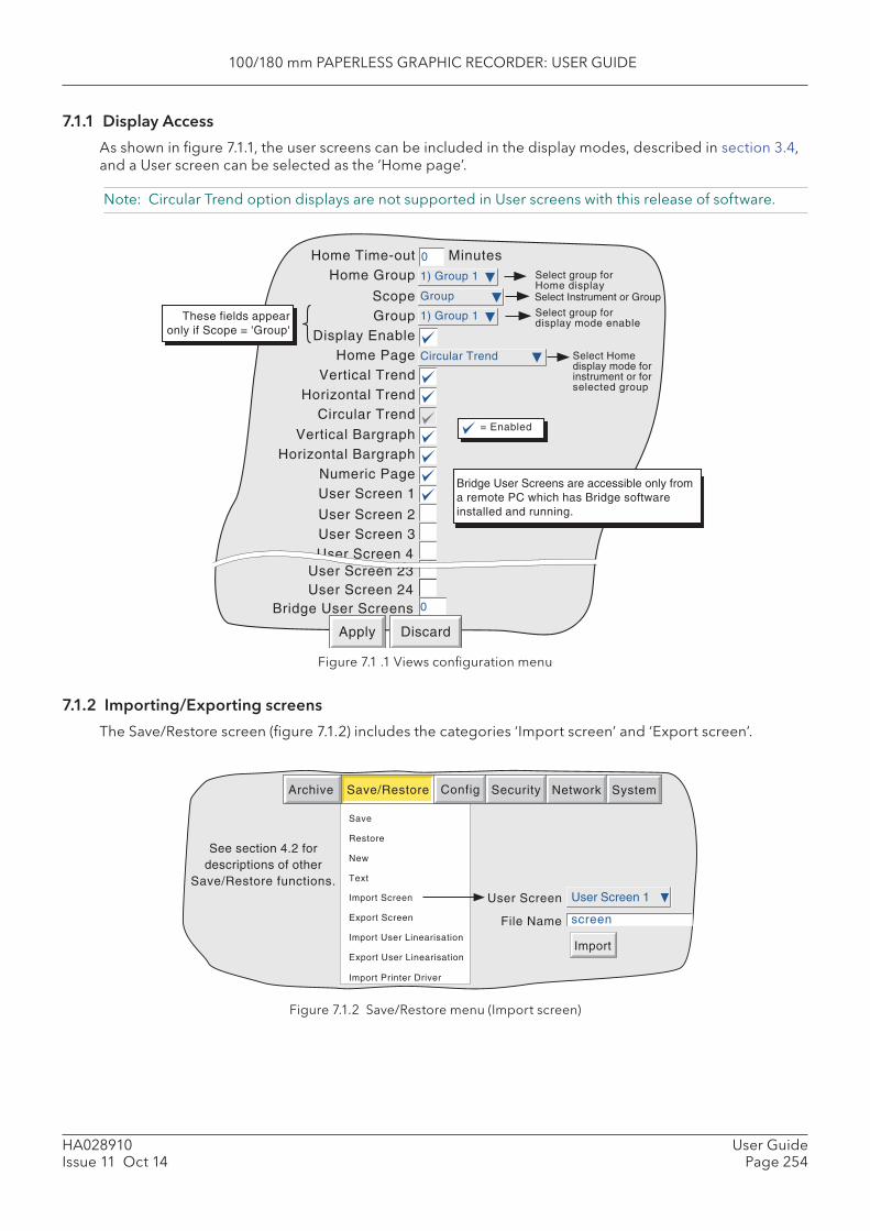
100/180 mm PAPERLESS GRAPHIC RECORDER: USER GUIDE
HA028910Issue 11 Oct 14
User GuidePage 254
7.1.1 Display Access
As shown in fi gure 7.1.1, the user screens can be included in the display modes, described in section 3.4, and a User screen can be selected as the ‘Home page’.
Note: Circular Trend option displays are not supported in User screens with this release of software.
Figure 7.1 .1 Views confi guration menu
7.1.2 Importing/Exporting screens
The Save/Restore screen (fi gure 7.1.2) includes the categories ‘Import screen’ and ‘Export screen’.
Figure 7.1.2 Save/Restore menu (Import screen)
Save
Restore
New
Text
Archive SystemSave/Restore Config Security Network
Import Screen
Export Screen File Name
User Screen
Import
See section 4.2 fordescriptions of other
Save/Restore functions.
Import User Linearisation
Export User Linearisation
User Screen 1
screen
Import Printer Driver
Select Homedisplay mode forinstrument or forselected group
= Enabled
Home Time-outHome Group
ScopeGroup
Display EnableHome Page
Vertical TrendHorizontal Trend
Vertical BargraphHorizontal Bargraph
Numeric PageUser Screen 1
User Screen 2User Screen 3User Screen 4
1) Group 1
Apply Discard
0
Group
1) Group 1
Circular Trend
Select group forHome display
Select group fordisplay mode enable
These fields appearonly if Scope = 'Group'
Select Instrument or Group
Minutes
Circular Trend
User Screen 23User Screen 24
Bridge User Screens
Bridge User Screens are accessible only froma remote PC which has Bridge softwareinstalled and running.
0
100/180 mm PAPERLESS GRAPHIC RECORDER: USER GUIDE
HA028910Issue 11 Oct 14
User GuidePage 255
7.1.2 IMPORTING/EXPORTING SCREENS (Cont.)
IMPORTING SCREENS
Touching the fi lename area, allows a previously created user screen to be selected either from the Flash memory or from disk to be imported. The User Screen picklist allows the user to defi ne which User screen is to be ‘replaced’ by the imported fi le.
EXPORTING SCREENS
Allows user screens to be exported to Flash memory, or disk, The operator can assign a suitable fi lena-me before exporting.
7.2 DISPLAY CREATIONThe following description is an attempt to show how to create a simple screen layout. The technique used is to defi ne an object, then to specify its size, and where its top left corner is to be located on the screen.
The option offers two levels of sophistication - basic and advanced. The basic system defi nes size, posi-tion, fi ll colour etc. for components (section 7.3.1). Advanced parameters allow a more sophisticated fi ne-tuning of the appearance of the components
Note: X is horizontal, increasing rightwards. Y is vertical, increasing downwards. (Top left corner is 0,0)
As implied in fi gure 7.2.3a, screen component position and dimensions can be specifi ed as percentage, absolute pixels or relative pixels. Percentage is ‘percentage of screen size’. Absolute pixels allow posi-tion and/or dimensions to be defi ned as an absolute number of pixels. Relative pixels are the same as absolute pixels, except that if the display is rescaled on, say, a pc screen, the absolute pixel object will remain unchanged, whereas the relative pixel object will scale appropriately. Similarly, for transfer from an XGA screen recorder to a 1/4VGA recorder or vice-versa.
7.2.1 Before starting
Before starting to lay the screen out:
1. The user must have ‘full confi guration’ access permission. 2. One or more user screens must be enabled in Views Confi guration (section 7.1.1)3. A layout plan is produced, with all the required screen’s components listed with their top left corner
co-ordinates, their widths and heights, and where appropriate background and foreground colours.
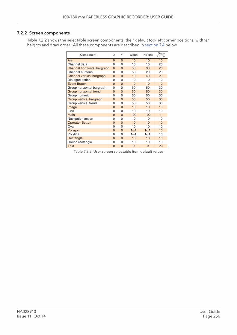
100/180 mm PAPERLESS GRAPHIC RECORDER: USER GUIDE
HA028910Issue 11 Oct 14
User GuidePage 256
7.2.2 Screen components
Table 7.2.2 shows the selectable screen components, their default top-left corner positions, widths/heights and draw order. All these components are described in section 7.4 below.
Table 7.2.2 User screen selectable item default values
Arc 0 0 10 10 10Channel data 0 0 10 10 20Channel horizontal bargraph 0 0 50 30 20Channel numeric 0 0 50 20 20Channel vertical bargraph 0 0 10 40 20Dialogue action 0 0 10 10 10Event Button 0 0 10 10 10Group horizontal bargraph 0 0 50 50 30Group horizontal trend 0 0 50 50 30Group numeric 0 0 50 50 30Group vertical bargraph 0 0 50 50 30Group vertical trend 0 0 50 50 30Image 0 0 10 10 10Line 0 0 10 10 10Main 0 0 100 100 1Navigation action 0 0 10 10 10Operator Button 0 0 10 10 10Oval 0 0 10 10 10Polygon 0 0 N/A N/A 10Polyline 0 0 N/A N/A 10Rectangle 0 0 10 10 10Round rectangle 0 0 10 10 10Text 0 0 0 0 20
Component DrawOrderX Y Width Height
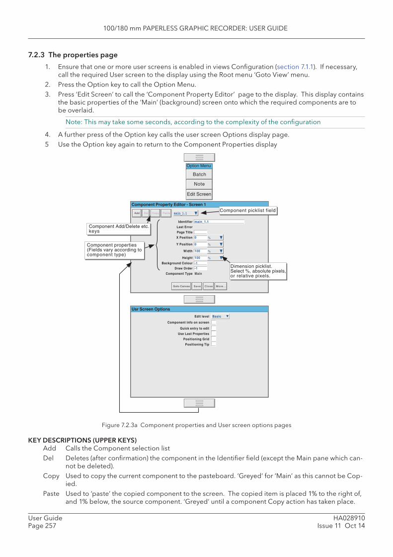
100/180 mm PAPERLESS GRAPHIC RECORDER: USER GUIDE
HA028910Issue 11 Oct 14
User GuidePage 257
7.2.3 The properties page
1. Ensure that one or more user screens is enabled in views Confi guration (section 7.1.1). If necessary, call the required User screen to the display using the Root menu ‘Goto View’ menu.
2. Press the Option key to call the Option Menu. 3. Press ‘Edit Screen’ to call the ‘Component Property Editor’ page to the display. This display contains
the basic properties of the ‘Main’ (background) screen onto which the required components are to be overlaid.
Note: This may take some seconds, according to the complexity of the confi guration
4. A further press of the Option key calls the user screen Options display page. 5 Use the Option key again to return to the Component Properties display
Figure 7.2.3a Component properties and User screen options pages
KEY DESCRIPTIONS (UPPER KEYS) Add Calls the Component selection list Del Deletes (after confi rmation) the component in the Identifi er fi eld (except the Main pane which can-
not be deleted). Copy Used to copy the current component to the pasteboard. ‘Greyed’ for ‘Main’ as this cannot be Cop-
ied. Paste Used to ‘paste’ the copied component to the screen. The copied item is placed 1% to the right of,
and 1% below, the source component. ‘Greyed’ until a component Copy action has taken place.
Note
Batch
Option Menu
Edit Screen
Component Property Editor - Screen 1
Identifier
Last Error
Page Title
X Position
Y Position
Width
Height
Draw Order
Component Type Main
Dimension picklist.Select %, absolute pixels,or relative pixels.
Component properties(Fields vary according tocomponent type)
Background Colour
Goto Canvas Save Close More. . .
Add Del Copy Paste
Component Add/Delete etc.keys
Component picklist field
Usr Screen Options
Edit level
Component info on screen
Quick entry to edit
Basic
Use Last Properties
Positioning Grid
Positioning Tip
main_1.1
main_1.1
-1
100
100
0
0 %
%
%
%
-1
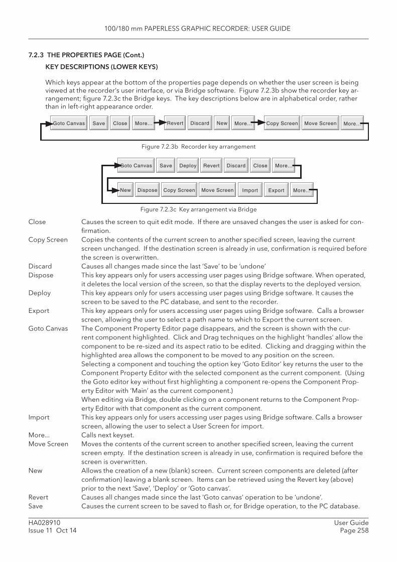
100/180 mm PAPERLESS GRAPHIC RECORDER: USER GUIDE
HA028910Issue 11 Oct 14
User GuidePage 258
7.2.3 THE PROPERTIES PAGE (Cont.)
KEY DESCRIPTIONS (LOWER KEYS)
Which keys appear at the bottom of the properties page depends on whether the user screen is being viewed at the recorder’s user interface, or via Bridge software. Figure 7.2.3b show the recorder key ar-rangement; fi gure 7.2.3c the Bridge keys. The key descriptions below are in alphabetical order, rather than in left-right appearance order.
Figure 7.2.3b Recorder key arrangement
Goto Canvas Save Close More... Revert Discard New More... Copy Screen Move Screen More...
Goto Canvas Save Close More...Revert DiscardDeploy
New More...Copy Screen Move ScreenDispose Import Export
Figure 7.2.3c Key arrangement via Bridge
Close Causes the screen to quit edit mode. If there are unsaved changes the user is asked for con-fi rmation.
Copy Screen Copies the contents of the current screen to another specifi ed screen, leaving the current screen unchanged. If the destination screen is already in use, confi rmation is required before the screen is overwritten.
Discard Causes all changes made since the last ‘Save’ to be ‘undone’ Dispose This key appears only for users accessing user pages using Bridge software. When operated,
it deletes the local version of the screen, so that the display reverts to the deployed version. Deploy This key appears only for users accessing user pages using Bridge software. It causes the
screen to be saved to the PC database, and sent to the recorder. Export This key appears only for users accessing user pages using Bridge software. Calls a browser
screen, allowing the user to select a path name to which to Export the current screen. Goto Canvas The Component Property Editor page disappears, and the screen is shown with the cur-
rent component highlighted. Click and Drag techniques on the highlight ‘handles’ allow the component to be re-sized and its aspect ratio to be edited. Clicking and dragging within the highlighted area allows the component to be moved to any position on the screen.Selecting a component and touching the option key ‘Goto Editor’ key returns the user to the Component Property Editor with the selected component as the current component. (Using the Goto editor key without fi rst highlighting a component re-opens the Component Prop-erty Editor with ‘Main’ as the current component.)When editing via Bridge, double clicking on a component returns to the Component Prop-erty Editor with that component as the current component.
Import This key appears only for users accessing user pages using Bridge software. Calls a browser screen, allowing the user to select a User Screen for import.
More... Calls next keyset. Move Screen Moves the contents of the current screen to another specifi ed screen, leaving the current
screen empty. If the destination screen is already in use, confi rmation is required before the screen is overwritten.
New Allows the creation of a new (blank) screen. Current screen components are deleted (after confi rmation) leaving a blank screen. Items can be retrieved using the Revert key (above) prior to the next ‘Save’, ‘Deploy’ or ‘Goto canvas’.
Revert Causes all changes made since the last ‘Goto canvas’ operation to be ‘undone’. Save Causes the current screen to be saved to fl ash or, for Bridge operation, to the PC database.
100/180 mm PAPERLESS GRAPHIC RECORDER: USER GUIDE
HA028910Issue 11 Oct 14
User GuidePage 259
7.2.3 THE PROPERTIES PAGE (Cont.)
OPTIONS PAGE ITEMS
Edit level Allows Basic or Advanced edit level to be selected for further use. Component info on screen Enabling this box causes a component description to appear at the top left corner
of each component. This description is in the form: Identifi er(X,Y)+[∂X,∂Y], where X and Y defi nes the top left corner position in pixels, and ∂X and ∂Y are the width and height of the component in pixels. The identifi er is the component name as appears in the Identifi er fi eld of the Component Property Editor page.
Quick entry to edit If selected, this function allows direct entry from the user screen being edited to the Component Property editor page, without the options menu fi rst appearing offering the choice of ‘Batch’ or ‘Edit Screen’.
If Quick entry is selected, the option menu does not appear when the option key is touched. The Batch status page can be called by touching the ‘Page Name’ area at the top of the screen, as an alternative to the option menu. Quick entry has no effect on screens other than user screens.
Use Last properties If selected, then all the common attributes (e.g. position, size, colours etc.) of the most recently edited object are applied to the next component to be added.
Positioning Grid Causes a grid to appear on the ‘Goto canvas’ screen to help in component layout Positioning tip If enabled, then hovering over the highlighted item in a ‘goto Canvas’ screen causes
the coordinates of the top left corner of the component to appear, in whatever units (%, pixels etc.) are selected for the component. The fi rst number gives the ‘X’ (left-right) co-ordinate; the second gives the ‘Y’ (up-down) position.Clicking the left mouse key within a component causes the coordinates of the top left corner of the component to appear, in whatever units (%, pixels etc.) are selected for the component.
Clicking the left mouse key outside a component, shows the co-ordinates of the mouse cursor tip. To see these co-ordinates within a component, the mouse must be click-dragged from outside the component.
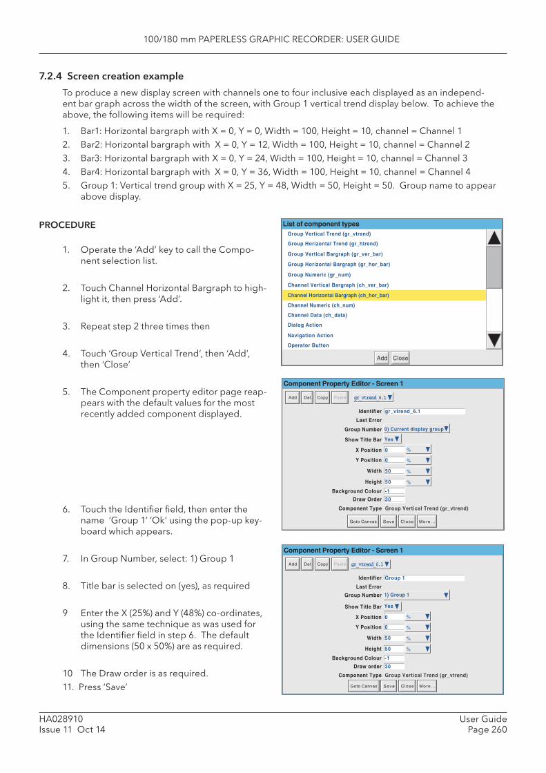
100/180 mm PAPERLESS GRAPHIC RECORDER: USER GUIDE
HA028910Issue 11 Oct 14
User GuidePage 260
7.2.4 Screen creation example
To produce a new display screen with channels one to four inclusive each displayed as an independ-ent bar graph across the width of the screen, with Group 1 vertical trend display below. To achieve the above, the following items will be required:
1. Bar1: Horizontal bargraph with X = 0, Y = 0, Width = 100, Height = 10, channel = Channel 12. Bar2: Horizontal bargraph with X = 0, Y = 12, Width = 100, Height = 10, channel = Channel 23. Bar3: Horizontal bargraph with X = 0, Y = 24, Width = 100, Height = 10, channel = Channel 34. Bar4: Horizontal bargraph with X = 0, Y = 36, Width = 100, Height = 10, channel = Channel 45. Group 1: Vertical trend group with X = 25, Y = 48, Width = 50, Height = 50. Group name to appear
above display.
PROCEDURE
1. Operate the ‘Add’ key to call the Compo-nent selection list.
2. Touch Channel Horizontal Bargraph to high-light it, then press ‘Add’.
3. Repeat step 2 three times then
4. Touch ‘Group Vertical Trend’, then ‘Add’, then ‘Close’
5. The Component property editor page reap-pears with the default values for the most recently added component displayed.
6. Touch the Identifi er fi eld, then enter the name ‘Group 1’ ‘Ok’ using the pop-up key-board which appears.
7. In Group Number, select: 1) Group 1
8. Title bar is selected on (yes), as required
9 Enter the X (25%) and Y (48%) co-ordinates, using the same technique as was used for the Identifi er fi eld in step 6. The default dimensions (50 x 50%) are as required.
10 The Draw order is as required.11. Press ‘Save’
Component Property Editor - Screen 1
gr_vtrend_6.1
Identifier gr_vtrend_6.1
Last Error
X Position
Y Position
Width
Height
Background Colour
Component Type Group Vertical Trend (gr_vtrend)
-1
50
50
0
0 %
%
%
%
Group Number 0) Current display group
Show Title Bar Yes
Draw Order 30
Add Del Copy Paste
Goto Canvas Save Close More. . .
Identifier
Last Error
X Position
Group Number
Show Title Bar
Component Property Editor - Screen 1
Y Position
Width
Height
Background Colour
Component Type Group Vertical Trend (gr_vtrend)
Draw order
Add Del Copy Paste gr_vtrend_6.1
Group 1
-1
50
50
0
0 %
%
%
%
1) Group 1
Yes
30
Goto Canvas Save Close More. . .
List of component typesGroup Vertical Trend (gr_vtrend)
Group Horizontal Trend (gr_htrend)
Channel Numeric (ch_num)
Group Numeric (gr_num)
Channel Vertical Bargraph (ch_ver_bar)
Group Horizontal Bargraph (gr_hor_bar)
Channel Data (ch_data)
Navigation Action
Operator Button
Group Vertical Bargraph (gr_ver_bar)
Dialog Action
CloseAdd
Channel Horizontal Bargraph (ch_hor_bar)
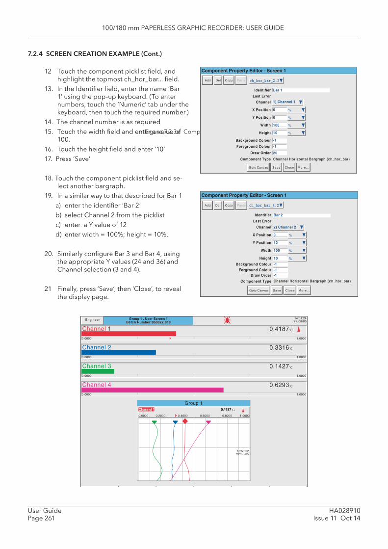
100/180 mm PAPERLESS GRAPHIC RECORDER: USER GUIDE
HA028910Issue 11 Oct 14
User GuidePage 261
Figure 7.2.3d Complete user screen
7.2.4 SCREEN CREATION EXAMPLE (Cont.)
12 Touch the component picklist fi eld, and highlight the topmost ch_hor_bar... fi eld.
13. In the Identifi er fi eld, enter the name ‘Bar 1’ using the pop-up keyboard. (To enter numbers, touch the ‘Numeric’ tab under the keyboard, then touch the required number.)
14. The channel number is as required 15. Touch the width fi eld and enter a value of
100.16. Touch the height fi eld and enter ‘10’17. Press ‘Save’
18. Touch the component picklist fi eld and se-lect another bargraph.
19. In a similar way to that described for Bar 1 a) enter the identifi er ‘Bar 2’ b) select Channel 2 from the picklist c) enter a Y value of 12 d) enter width = 100%; height = 10%.
20. Similarly confi gure Bar 3 and Bar 4, using the appropriate Y values (24 and 36) and Channel selection (3 and 4).
21 Finally, press ‘Save’, then ‘Close’, to reveal the display page.
ch_hor_bar_2.2
Identifier Bar 1
Last Error
X Position 0 %
Y Position
Width
Height
Foreground Colour
Component Type
-1
10
100
0 %
%
%
Channel Horizontal Bargraph (ch_hor_bar)
Channel 1) Channel 1
Background Colour -1
Draw Order 20
Add Del Copy Paste
Component Property Editor - Screen 1
Goto Canvas Save Close More. . .
Identifier
Component Property Editor - Screen 1
Last Error
X Position
Y Position
Width
Height
Background Colour
Component Type Channel Horizontal Bargraph (ch_hor_bar)
Channel
Forground ColourDraw Order
Add Del Copy Paste ch_hor_bar_4.2
Bar 2
0 %
-1
10
100
12 %
%
%
2) Channel 2
-1-1
Goto Canvas Save Close More. . .
Group 1 . User Screen 1Batch Number:050822.010
14:01:2422/08/05Engineer
1.00000.0000
0.4187˚CChannel 1
1.00000.0000
0.3316˚CChannel 2
1.00000.0000
0.1427˚CChannel 3
1.00000.0000
0.6293˚CChannel 4
13:59:0222/08/05
0.0000 0.2000 0.4000 0.6000 0.8000 1.0000
Channel 1 0.4187˚C
Group 1
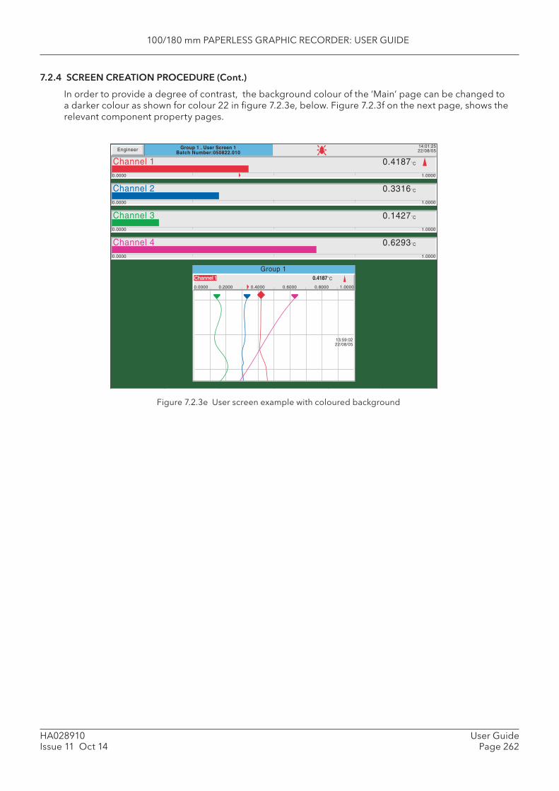
100/180 mm PAPERLESS GRAPHIC RECORDER: USER GUIDE
HA028910Issue 11 Oct 14
User GuidePage 262
7.2.4 SCREEN CREATION PROCEDURE (Cont.)
In order to provide a degree of contrast, the background colour of the ‘Main’ page can be changed to a darker colour as shown for colour 22 in fi gure 7.2.3e, below. Figure 7.2.3f on the next page, shows the relevant component property pages.
Figure 7.2.3e User screen example with coloured background
Group 1 . User Screen 1Batch Number:050822.010
14:01:2522/08/05Engineer
1.00000.0000
0.4187˚CChannel 1
1.00000.0000
0.3316˚CChannel 2
1.00000.0000
0.1427˚CChannel 3
1.00000.0000
0.6293˚CChannel 4
13:59:0222/08/05
0.0000 0.2000 0.4000 0.6000 0.8000 1.0000
Channel 1 0.4187˚C
Group 1
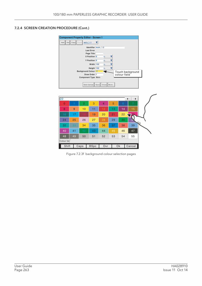
100/180 mm PAPERLESS GRAPHIC RECORDER: USER GUIDE
HA028910Issue 11 Oct 14
User GuidePage 263
7.2.4 SCREEN CREATION PROCEDURE (Cont.)
Figure 7.2.3f background colour selection pages
0
8
16
24
32
40
48
1
9
17
25
33
41
49
2
10
18
26
34
42
50
3
11
19
27
35
43
51
4
12
20
28
36
44
52
5
13
21
29
37
45
53
6
14
22
30
38
46
54
7
15
23
31
39
47
55
Shift Caps BSpc Ovr Ok Cancel
Colour list
22
main_1.2
Identifier main_1.2
Component Property Editor - Screen 1
Last Error
Page Title
X Position
Y Position
Width
Height
Background Colour
Component Type Main
-1
100
100
0
0 %
%
%
%
Touch backgroundcolour fieldDraw Order 1
Add Del Copy Paste
Goto Canvas Save Close More. . .
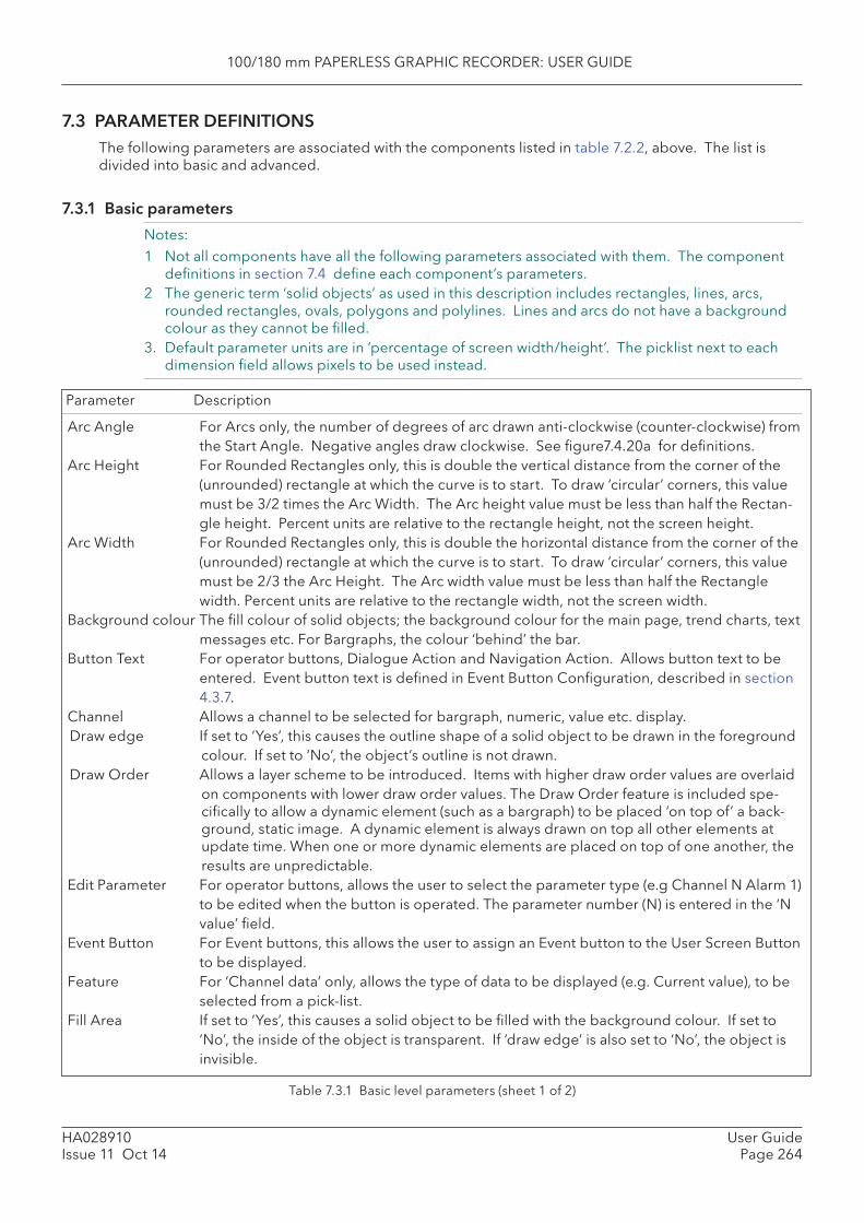
100/180 mm PAPERLESS GRAPHIC RECORDER: USER GUIDE
HA028910Issue 11 Oct 14
User GuidePage 264
7.3 PAR AMETER DEFINITIONSThe following parameters are associated with the components listed in table 7.2.2, above. The list is divided into basic and advanced.
7.3.1 Basic parameters
Notes:1 Not all components have all the following parameters associated with them. The component
defi nitions in section 7.4 defi ne each component’s parameters.2 The generic term ‘solid objects’ as used in this description includes rectangles, lines, arcs,
rounded rectangles, ovals, polygons and polylines. Lines and arcs do not have a background colour as they cannot be fi lled.
3. Default parameter units are in ‘percentage of screen width/height’. The picklist next to each dimension fi eld allows pixels to be used instead.
Table 7.3.1 Basic level parameters (sheet 1 of 2)
Arc Angle For Arcs only, the number of degrees of arc drawn anti-clockwise (counter-clockwise) from the Start Angle. Negative angles draw clockwise. See fi gure7.4.20a for defi nitions.
Arc Height For Rounded Rectangles only, this is double the vertical distance from the corner of the (unrounded) rectangle at which the curve is to start. To draw ‘circular’ corners, this value must be 3/2 times the Arc Width. The Arc height value must be less than half the Rectan-gle height. Percent units are relative to the rectangle height, not the screen height.
Arc Width For Rounded Rectangles only, this is double the horizontal distance from the corner of the (unrounded) rectangle at which the curve is to start. To draw ‘circular’ corners, this value must be 2/3 the Arc Height. The Arc width value must be less than half the Rectangle width. Percent units are relative to the rectangle width, not the screen width.
Background colour The fi ll colour of solid objects; the background colour for the main page, trend charts, text messages etc. For Bargraphs, the colour ‘behind’ the bar.
Button Text For operator buttons, Dialogue Action and Navigation Action. Allows button text to be entered. Event button text is defi ned in Event Button Confi guration, described in section 4.3.7.
Channel Allows a channel to be selected for bargraph, numeric, value etc. display. Draw edge If set to ‘Yes’, this causes the outline shape of a solid object to be drawn in the foreground
colour. If set to ‘No’, the object’s outline is not drawn.Draw Order Allows a layer scheme to be introduced. Items with higher draw order values are overlaid
on components with lower draw order values. The Draw Order feature is included spe-cifi cally to allow a dynamic element (such as a bargraph) to be placed ‘on top of’ a back-ground, static image. A dynamic element is always drawn on top all other elements at update time. When one or more dynamic elements are placed on top of one another, the results are unpredictable.
Edit Parameter For operator buttons, allows the user to select the parameter type (e.g Channel N Alarm 1) to be edited when the button is operated. The parameter number (N) is entered in the ‘N value’ fi eld.
Event Button For Event buttons, this allows the user to assign an Event button to the User Screen Button to be displayed.
Feature For ‘Channel data’ only, allows the type of data to be displayed (e.g. Current value), to be selected from a pick-list.
Fill Area If set to ‘Yes’, this causes a solid object to be fi lled with the background colour. If set to ‘No’, the inside of the object is transparent. If ‘draw edge’ is also set to ‘No’, the object is invisible.
Parameter Description
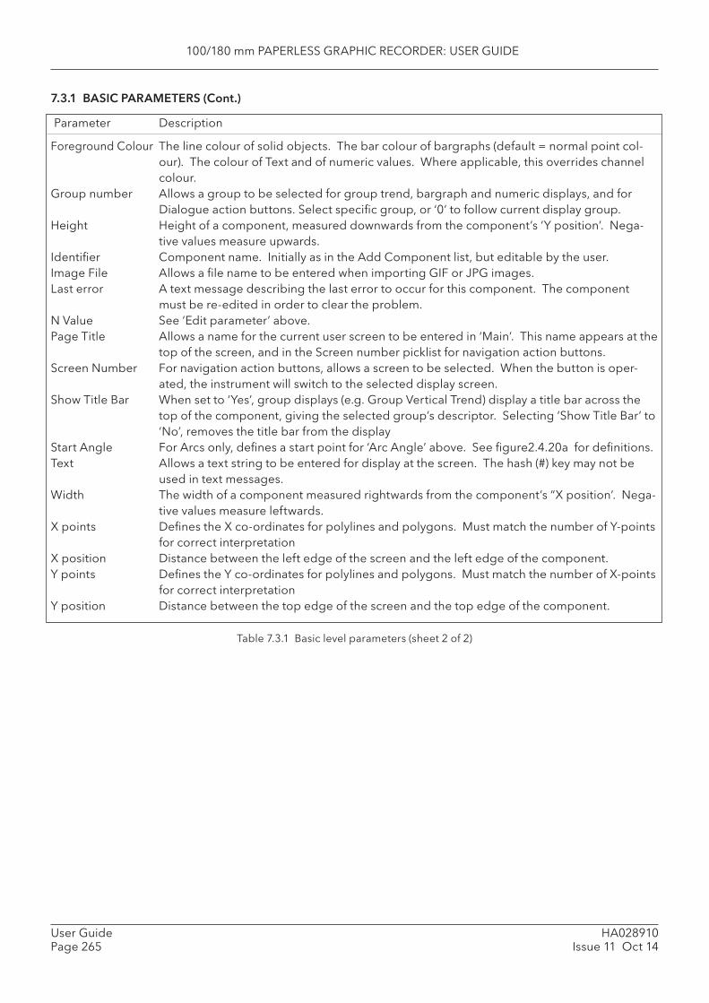
100/180 mm PAPERLESS GRAPHIC RECORDER: USER GUIDE
HA028910Issue 11 Oct 14
User GuidePage 265
7.3.1 BASIC PARAMETERS (Cont.)
Parameter Description
Foreground Colour The line colour of solid objects. The bar colour of bargraphs (default = normal point col-our). The colour of Text and of numeric values. Where applicable, this overrides channel colour.
Group number Allows a group to be selected for group trend, bargraph and numeric displays, and for Dialogue action buttons. Select specifi c group, or ‘0’ to follow current display group.
Height Height of a component, measured downwards from the component’s ‘Y position’. Nega-tive values measure upwards.
Identifi er Component name. Initially as in the Add Component list, but editable by the user. Image File Allows a fi le name to be entered when importing GIF or JPG images. Last error A text message describing the last error to occur for this component. The component
must be re-edited in order to clear the problem. N Value See ‘Edit parameter’ above. Page Title Allows a name for the current user screen to be entered in ‘Main’. This name appears at the
top of the screen, and in the Screen number picklist for navigation action buttons. Screen Number For navigation action buttons, allows a screen to be selected. When the button is oper-
ated, the instrument will switch to the selected display screen. Show Title Bar When set to ‘Yes’, group displays (e.g. Group Vertical Trend) display a title bar across the
top of the component, giving the selected group’s descriptor. Selecting ‘Show Title Bar’ to ‘No’, removes the title bar from the display
Start Angle For Arcs only, defi nes a start point for ‘Arc Angle’ above. See fi gure2.4.20a for defi nitions. Text Allows a text string to be entered for display at the screen. The hash (#) key may not be
used in text messages. Width The width of a component measured rightwards from the component’s “X position’. Nega-
tive values measure leftwards. X points Defi nes the X co-ordinates for polylines and polygons. Must match the number of Y-points
for correct interpretationX position Distance between the left edge of the screen and the left edge of the component. Y points Defi nes the Y co-ordinates for polylines and polygons. Must match the number of X-points
for correct interpretation Y position Distance between the top edge of the screen and the top edge of the component.
Table 7.3.1 Basic level parameters (sheet 2 of 2)
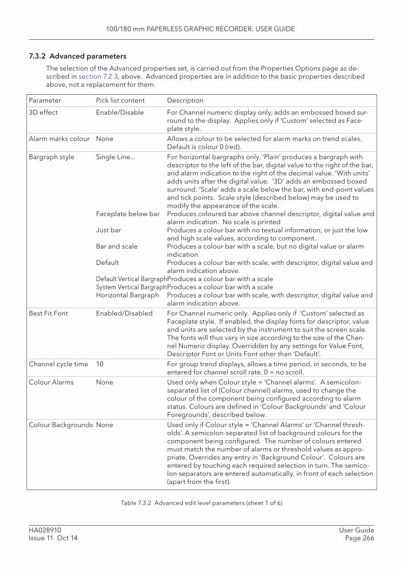
100/180 mm PAPERLESS GRAPHIC RECORDER: USER GUIDE
HA028910Issue 11 Oct 14
User GuidePage 266
7.3.2 Advanced parameters
The selection of the Advanced properties set, is carried out from the Properties Options page as de-scribed in section 7.2.3, above. Advanced properties are in addition to the basic properties described above, not a replacement for them.
Parameter Pick list content Description
Table 7.3.2 Advanced edit level parameters (sheet 1 of 6)
3D effect Enable/Disable For Channel numeric display only, adds an embossed boxed sur-round to the display. Applies only if ‘Custom’ selected as Face-plate style.
Alarm marks colour None Allows a colour to be selected for alarm marks on trend scales. Default is colour 0 (red).
Bargraph style Single Line... For horizontal bargraphs only. ‘Plain’ produces a bargraph with descriptor to the left of the bar, digital value to the right of the bar, and alarm indication to the right of the decimal value. ‘With units’ adds units after the digital value. ‘3D’ adds an embossed boxed surround. ‘Scale’ adds a scale below the bar, with end-point values and tick points. Scale style (described below) may be used to modify the appearance of the scale.
Faceplate below bar Produces coloured bar above channel descriptor, digital value and alarm indication. No scale is printed
Just bar Produces a colour bar with no textual information, or just the low and high scale values, according to component.
Bar and scale Produces a colour bar with a scale, but no digital value or alarm indication
Default Produces a colour bar with scale, with descriptor, digital value and alarm indication above.
Default Vertical Bargraph Produces a colour bar with a scale System Vertical Bargraph Produces a colour bar with a scale Horizontal Bargraph Produces a colour bar with scale, with descriptor, digital value and
alarm indication above. Best Fit Font Enabled/Disabled For Channel numeric only. Applies only if ‘Custom’ selected as
Faceplate style. If enabled, the display fonts for descriptor, value and units are selected by the instrument to suit the screen scale. The fonts will thus vary in size according to the size of the Chan-nel Numeric display. Overridden by any settings for Value Font, Descriptor Font or Units Font other than ‘Default’.
Channel cycle time 10 For group trend displays, allows a time period, in seconds, to be entered for channel scroll rate. 0 = no scroll.
Colour Alarms None Used only when Colour style = ‘Channel alarms’. A semicolon-separated list of (Colour channel) alarms, used to change the colour of the component being confi gured according to alarm status. Colours are defi ned in ‘Colour Backgrounds’ and ‘Colour Foregrounds’, described below.
Colour Backgrounds None Used only if Colour style = ‘Channel Alarms’ or ‘Channel thresh-olds’. A semicolon-separated list of background colours for the component being confi gured. The number of colours entered must match the number of alarms or threshold values as appro-priate. Overrides any entry in ‘Background Colour’. Colours are entered by touching each required selection in turn. The semico-lon separators are entered automatically, in front of each selection (apart from the fi rst).
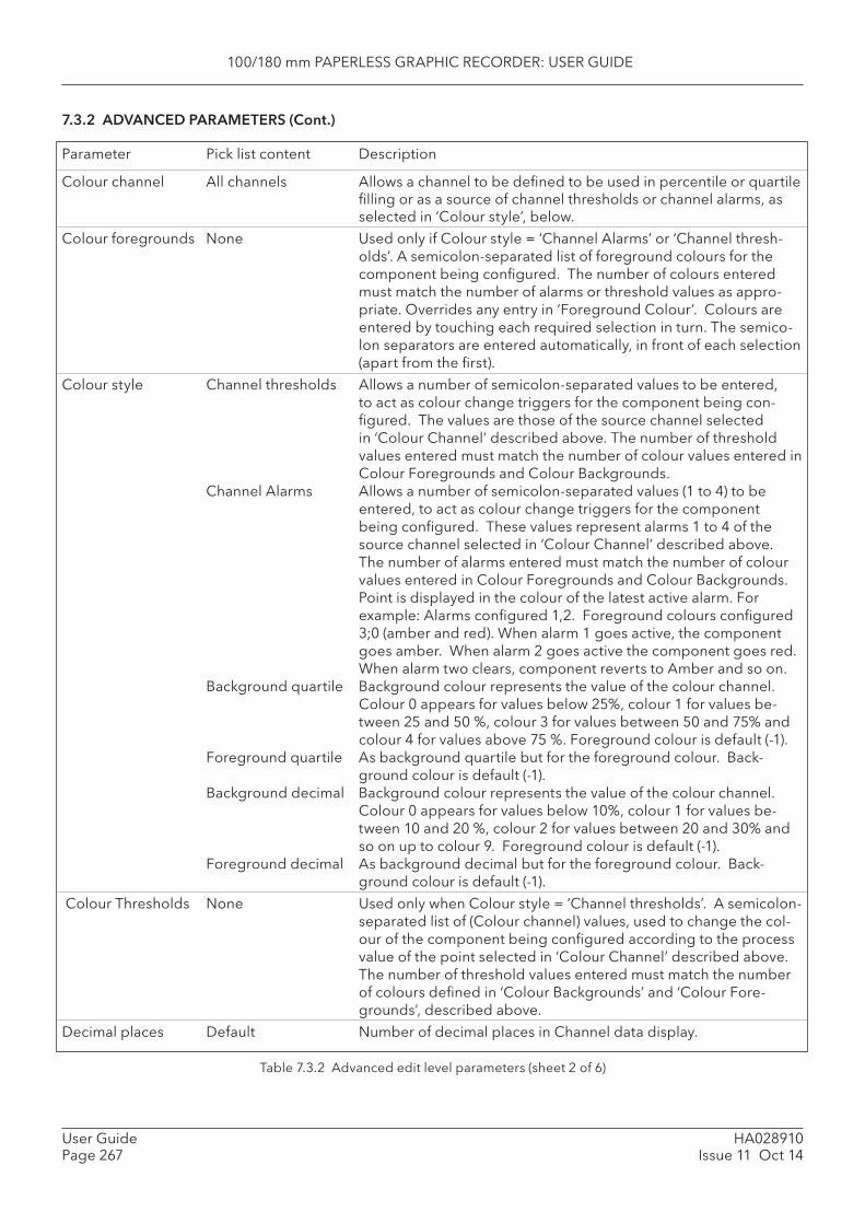
100/180 mm PAPERLESS GRAPHIC RECORDER: USER GUIDE
HA028910Issue 11 Oct 14
User GuidePage 267
Colour channel All channels Allows a channel to be defi ned to be used in percentile or quartile fi lling or as a source of channel thresholds or channel alarms, as selected in ‘Colour style’, below.
Colour foregrounds None Used only if Colour style = ‘Channel Alarms’ or ‘Channel thresh-olds’. A semicolon-separated list of foreground colours for the component being confi gured. The number of colours entered must match the number of alarms or threshold values as appro-priate. Overrides any entry in ‘Foreground Colour’. Colours are entered by touching each required selection in turn. The semico-lon separators are entered automatically, in front of each selection (apart from the fi rst).
Colour style Channel thresholds Allows a number of semicolon-separated values to be entered, to act as colour change triggers for the component being con-fi gured. The values are those of the source channel selected in ‘Colour Channel’ described above. The number of threshold values entered must match the number of colour values entered in Colour Foregrounds and Colour Backgrounds.
Channel Alarms Allows a number of semicolon-separated values (1 to 4) to be entered, to act as colour change triggers for the component being confi gured. These values represent alarms 1 to 4 of the source channel selected in ‘Colour Channel’ described above. The number of alarms entered must match the number of colour values entered in Colour Foregrounds and Colour Backgrounds. Point is displayed in the colour of the latest active alarm. For example: Alarms confi gured 1,2. Foreground colours confi gured 3;0 (amber and red). When alarm 1 goes active, the component goes amber. When alarm 2 goes active the component goes red. When alarm two clears, component reverts to Amber and so on.
Background quartile Background colour represents the value of the colour channel. Colour 0 appears for values below 25%, colour 1 for values be-tween 25 and 50 %, colour 3 for values between 50 and 75% and colour 4 for values above 75 %. Foreground colour is default (-1).
Foreground quartile As background quartile but for the foreground colour. Back-ground colour is default (-1).
Background decimal Background colour represents the value of the colour channel. Colour 0 appears for values below 10%, colour 1 for values be-tween 10 and 20 %, colour 2 for values between 20 and 30% and so on up to colour 9. Foreground colour is default (-1).
Foreground decimal As background decimal but for the foreground colour. Back-ground colour is default (-1).
Colour Thresholds None Used only when Colour style = ‘Channel thresholds’. A semicolon-separated list of (Colour channel) values, used to change the col-our of the component being confi gured according to the process value of the point selected in ‘Colour Channel’ described above. The number of threshold values entered must match the number of colours defi ned in ‘Colour Backgrounds’ and ‘Colour Fore-grounds’, described above.
Decimal places Default Number of decimal places in Channel data display.
7.3.2 ADVANCED PARAMETERS (Cont.)
Parameter Pick list content Description
Table 7.3.2 Advanced edit level parameters (sheet 2 of 6)
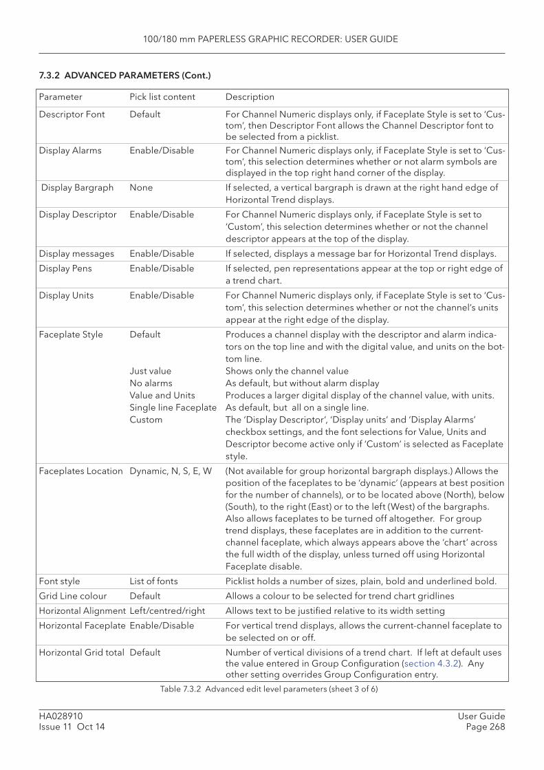
100/180 mm PAPERLESS GRAPHIC RECORDER: USER GUIDE
HA028910Issue 11 Oct 14
User GuidePage 268
Descriptor Font Default For Channel Numeric displays only, if Faceplate Style is set to ‘Cus-tom’, then Descriptor Font allows the Channel Descriptor font to be selected from a picklist.
Display Alarms Enable/Disable For Channel Numeric displays only, if Faceplate Style is set to ‘Cus-tom’, this selection determines whether or not alarm symbols are displayed in the top right hand corner of the display.
Display Bargraph None If selected, a vertical bargraph is drawn at the right hand edge of Horizontal Trend displays.
Display Descriptor Enable/Disable For Channel Numeric displays only, if Faceplate Style is set to ‘Custom’, this selection determines whether or not the channel descriptor appears at the top of the display.
Display messages Enable/Disable If selected, displays a message bar for Horizontal Trend displays.
Display Pens Enable/Disable If selected, pen representations appear at the top or right edge of a trend chart.
Display Units Enable/Disable For Channel Numeric displays only, if Faceplate Style is set to ‘Cus-tom’, this selection determines whether or not the channel’s units appear at the right edge of the display.
Faceplate Style Default Produces a channel display with the descriptor and alarm indica-tors on the top line and with the digital value, and units on the bot-tom line.
Just value Shows only the channel value No alarms As default, but without alarm display Value and Units Produces a larger digital display of the channel value, with units. Single line Faceplate As default, but all on a single line. Custom The ‘Display Descriptor’, ‘Display units’ and ‘Display Alarms’
checkbox settings, and the font selections for Value, Units and Descriptor become active only if ‘Custom’ is selected as Faceplate style.
Faceplates Location Dynamic, N, S, E, W (Not available for group horizontal bargraph displays.) Allows the position of the faceplates to be ‘dynamic’ (appears at best position for the number of channels), or to be located above (North), below (South), to the right (East) or to the left (West) of the bargraphs. Also allows faceplates to be turned off altogether. For group trend displays, these faceplates are in addition to the current-channel faceplate, which always appears above the ‘chart’ across the full width of the display, unless turned off using Horizontal Faceplate disable.
Font style List of fonts Picklist holds a number of sizes, plain, bold and underlined bold.
Grid Line colour Default Allows a colour to be selected for trend chart gridlines
Horizontal Alignment Left/centred/right Allows text to be justifi ed relative to its width setting
Horizontal Faceplate Enable/Disable For vertical trend displays, allows the current-channel faceplate to be selected on or off.
Horizontal Grid total Default Number of vertical divisions of a trend chart. If left at default uses the value entered in Group Confi guration (section 4.3.2). Any other setting overrides Group Confi guration entry.
7.3.2 ADVANCED PARAMETERS (Cont.)
Parameter Pick list content Description
Table 7.3.2 Advanced edit level parameters (sheet 3 of 6)
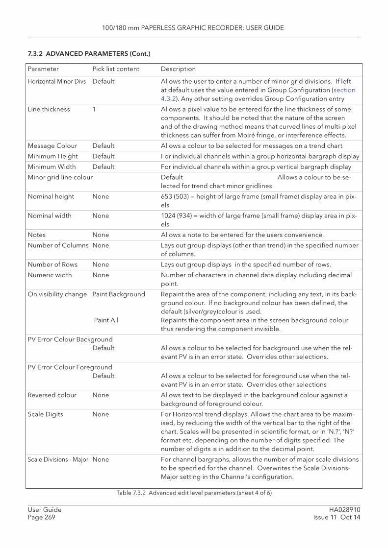
100/180 mm PAPERLESS GRAPHIC RECORDER: USER GUIDE
HA028910Issue 11 Oct 14
User GuidePage 269
Horizontal Minor Divs Default Allows the user to enter a number of minor grid divisions. If left at default uses the value entered in Group Confi guration (section 4.3.2). Any other setting overrides Group Confi guration entry
Line thickness 1 Allows a pixel value to be entered for the line thickness of some components. It should be noted that the nature of the screen and of the drawing method means that curved lines of multi-pixel thickness can suffer from Moiré fringe, or interference effects.
Message Colour Default Allows a colour to be selected for messages on a trend chart
Minimum Height Default For individual channels within a group horizontal bargraph display
Minimum Width Default For individual channels within a group vertical bargraph display
Minor grid line colour Default Allows a colour to be se-lected for trend chart minor gridlines
Nominal height None 653 (503) = height of large frame (small frame) display area in pix-els
Nominal width None 1024 (934) = width of large frame (small frame) display area in pix-els
Notes None Allows a note to be entered for the users convenience.
Number of Columns None Lays out group displays (other than trend) in the specifi ed number of columns.
Number of Rows None Lays out group displays in the specifi ed number of rows.
Numeric width None Number of characters in channel data display including decimal point.
On visibility change Paint Background Repaint the area of the component, including any text, in its back-ground colour. If no background colour has been defi ned, the default (silver/grey)colour is used.
Paint All Repaints the component area in the screen background colour thus rendering the component invisible.
PV Error Colour Background Default Allows a colour to be selected for background use when the rel-
evant PV is in an error state. Overrides other selections.
PV Error Colour Foreground Default Allows a colour to be selected for foreground use when the rel-
evant PV is in an error state. Overrides other selections
Reversed colour None Allows text to be displayed in the background colour against a background of foreground colour.
Scale Digits None For Horizontal trend displays. Allows the chart area to be maxim-ised, by reducing the width of the vertical bar to the right of the chart. Scales will be presented in scientifi c format, or in ‘N.?’, ‘N?’ format etc. depending on the number of digits specifi ed. The number of digits is in addition to the decimal point.
Scale Divisions - Major None For channel bargraphs, allows the number of major scale divisions to be specifi ed for the channel. Overwrites the Scale Divisions-Major setting in the Channel’s confi guration.
7.3.2 ADVANCED PARAMETERS (Cont.)
Parameter Pick list content Description
Table 7.3.2 Advanced edit level parameters (sheet 4 of 6)
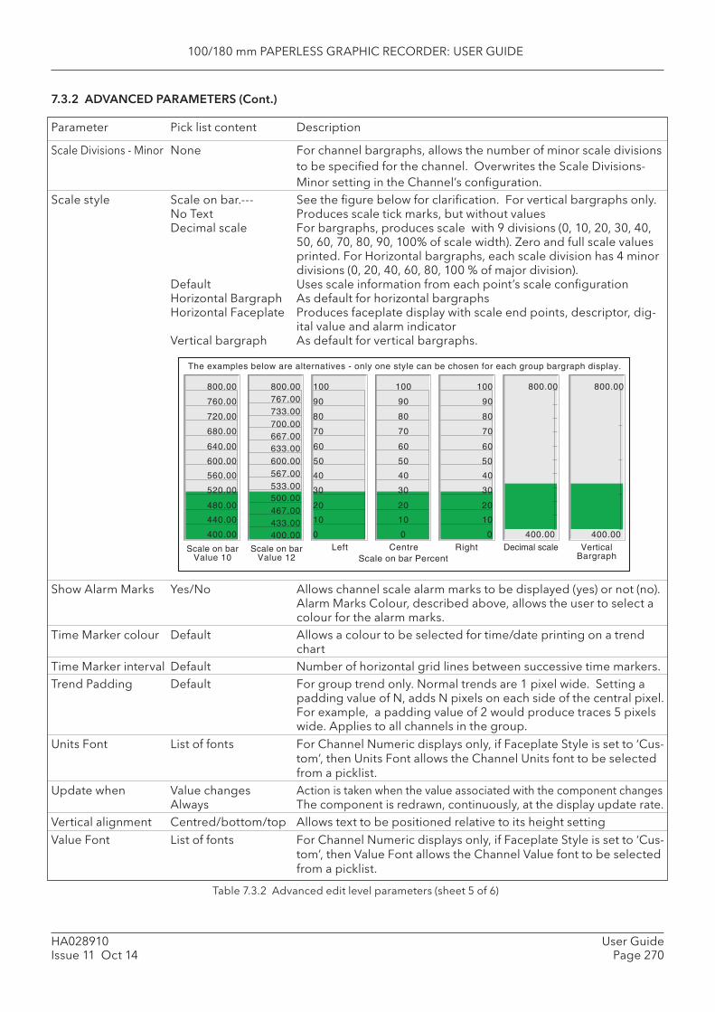
100/180 mm PAPERLESS GRAPHIC RECORDER: USER GUIDE
HA028910Issue 11 Oct 14
User GuidePage 270
Scale Divisions - Minor None For channel bargraphs, allows the number of minor scale divisions to be specifi ed for the channel. Overwrites the Scale Divisions-Minor setting in the Channel’s confi guration.
Scale style Scale on bar.--- See the fi gure below for clarifi cation. For vertical bargraphs only. No Text Produces scale tick marks, but without values Decimal scale For bargraphs, produces scale with 9 divisions (0, 10, 20, 30, 40,
50, 60, 70, 80, 90, 100% of scale width). Zero and full scale values printed. For Horizontal bargraphs, each scale division has 4 minor divisions (0, 20, 40, 60, 80, 100 % of major division).
Default Uses scale information from each point’s scale confi guration Horizontal Bargraph As default for horizontal bargraphs Horizontal Faceplate Produces faceplate display with scale end points, descriptor, dig-
ital value and alarm indicator Vertical bargraph As default for vertical bargraphs.
Table 7.3.2 Advanced edit level parameters (sheet 5 of 6)
7.3.2 ADVANCED PARAMETERS (Cont.)
Show Alarm Marks Yes/No Allows channel scale alarm marks to be displayed (yes) or not (no). Alarm Marks Colour, described above, allows the user to select a colour for the alarm marks.
Time Marker colour Default Allows a colour to be selected for time/date printing on a trend chart
Time Marker interval Default Number of horizontal grid lines between successive time markers. Trend Padding Default For group trend only. Normal trends are 1 pixel wide. Setting a
padding value of N, adds N pixels on each side of the central pixel. For example, a padding value of 2 would produce traces 5 pixels wide. Applies to all channels in the group.
Units Font List of fonts For Channel Numeric displays only, if Faceplate Style is set to ‘Cus-tom’, then Units Font allows the Channel Units font to be selected from a picklist.
Update when Value changes Action is taken when the value associated with the c omponent changes Always The component is redrawn, continuously, at the display update rate. Vertical alignment Centred/bottom/top Allows text to be positioned relative to its height setting Value Font List of fonts For Channel Numeric displays only, if Faceplate Style is set to ‘Cus-
tom’, then Value Font allows the Channel Value font to be selected from a picklist.
400.00
440.00
480.00
520.00
560.00
600.00
640.00
680.00
720.00
760.00
800.00
Scale on barValue 10
Scale on barValue 12
400.00433.00467.00
533.00567.00600.00633.00
700.00733.00767.00800.00
667.00
500.00
0
10
20
30
40
50
60
70
80
90
100
Scale on bar Percent
0
10
20
30
40
50
60
70
80
90
100
0
10
20
30
40
50
60
70
80
90
100
RightLeft Centre
400.00
800.00
Decimal scale
400.00
800.00
VerticalBargraph
The examples below are alternatives - only one style can be chosen for each group bargraph display.
Parameter Pick list content Description
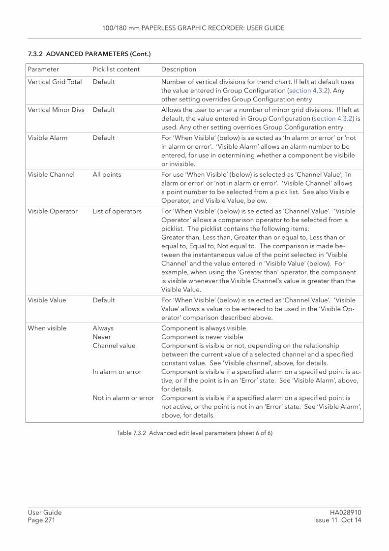
100/180 mm PAPERLESS GRAPHIC RECORDER: USER GUIDE
HA028910Issue 11 Oct 14
User GuidePage 271
Vertical Grid Total Default Number of vertical divisions for trend chart. If left at default uses the value entered in Group Confi guration (section 4.3.2). Any other setting overrides Group Confi guration entry
Vertical Minor Divs Default Allows the user to enter a number of minor grid divisions. If left at default, the value entered in Group Confi guration (section 4.3.2) is used. Any other setting overrides Group Confi guration entry
Visible Alarm Default For ‘When Visible’ (below) is selected as ‘In alarm or error’ or ‘not in alarm or error’. ‘Visible Alarm’ allows an alarm number to be entered, for use in determining whether a component be visibile or invisible.
Visible Channel All points For use ‘When Visible’ (below) is selected as ‘Channel Value’, ‘In alarm or error’ or ‘not in alarm or error’. ‘Visible Channel’ allows a point number to be selected from a pick list. See also Visible Operator, and Visible Value, below.
Visible Operator List of operators For ‘When Visible’ (below) is selected as ‘Channel Value’. ‘Visible Operator’ allows a comparison operator to be selected from a picklist. The picklist contains the following items:Greater than, Less than, Greater than or equal to, Less than or equal to, Equal to, Not equal to. The comparison is made be-tween the instantaneous value of the point selected in ‘Visible Channel’ and the value entered in ‘Visible Value’ (below). For example, when using the ‘Greater than’ operator, the component is visible whenever the Visible Channel’s value is greater than the Visible Value.
Visible Value Default For ‘When Visible’ (below) is selected as ‘Channel Value’. ‘Visible Value’ allows a value to be entered to be used in the ‘Visible Op-erator’ comparison described above.
When visible Always Component is always visible Never Component is never visible Channel value Component is visible or not, depending on the relationship
between the current value of a selected channel and a specifi ed constant value. See ‘Visible channel’, above, for details.
In alarm or error Component is visible if a specifi ed alarm on a specifi ed point is ac-tive, or if the point is in an ‘Error’ state. See ‘Visible Alarm’, above, for details.
Not in alarm or error Component is visible if a specifi ed alarm on a specifi ed point is not active, or the point is not in an ‘Error’ state. See ‘Visible Alarm’, above, for details.
7.3.2 ADVANCED PARAMETERS (Cont.)
Parameter Pick list content Description
Table 7.3.2 Advanced edit level parameters (sheet 6 of 6)
100/180 mm PAPERLESS GRAPHIC RECORDER: USER GUIDE
HA028910Issue 11 Oct 14
User GuidePage 272
7.4 COMPONENT DEFINITIONS
This section defi nes all the available components listed in table 7.2.2 in terms of their parameters. The components occur in the order in which they appear in the list.
7.4.1 Group Vertical/Horizontal Trend
This produces a display which mimics a recorder chart, for a selected group. All the functions (e.g. trend history) described in, section 3.4. The following unique parameters (fully described in table 7.3.2) are available for confi guration:
Background colour Allows the ‘chart’ to be drawn in the selected colour.Message Colour The colour of messages printed on the ‘Chart’.Time Marker Colour The colour of time/date printed on the ‘Chart’. Grid Line Colour The colour of the ‘Chart’ grid lines.Faceplates location Allows ‘group’ faceplates to be enabled/disabled, and when enabled allows the posi-
tion of the faceplates to be defi ned. These ‘group’ faceplates are additional to the current-channel faceplate which always appears above the chart, unless it has been disabled under ‘Horizontal faceplate’ (below).
Time Marker Interval Selects the number of horizontal chart lines between successive time markersVertical Grid Total Total number of vertical chart divisions. Horizontal Grid Total Total number of horizontal chart divisions.Trend Padding Sets thickness of traces.Channel cycle time Allows a number to be entered for the scrolling period between channels. 0 = Chan-
nel hold.Display Messages Allows message printing to be enabled/disabled.Display Bargraph For Horizontal trending only, allows the vertical bargraph display to be switched on
and off.Display Pens Allows the pen icons at the edge of the chart to be switched on and off.Horizontal Faceplate Allows the current-channel faceplate to be switched on and off.
7.4.2 Group vertical bargraph
Produces a vertical bargraph for a selected group in a format defi ned by ‘Bargraph Style’ and ‘Scale style’ described in table 7.3.2. The number of rows of bars can also be defi ned by the user, according to the overall size of the display, number of channels etc. The default value of zero means that the recorder will display what it ‘believes’ to be the most ergonomic number of rows.
The recorder attempts to fi t as many channel bars as possible into the width of the display. The default minimum width of a column is 6 mm. If there are more channels than can be fi tted into the display, a scroll bar device appears at the bottom edge to allow ‘hidden’ bars to be accessed.
The recorder attempts to fi t as many faceplates as possible into the height of the display. If there are more faceplates than can be fi tted into the display, a scroll bar device appears to allow ‘hidden’ face-plates to be accessed.
7.4.3 Group horizontal bargraph
Produces a group horizontal bargraph, for a selected group, in a format defi ned by ‘Bargraph Style’ and ‘Scale style’ described in table 7.3.2. The number of columns can also be defi ned by the user, according to the overall size of the display, minimum width, number of channels etc.
The recorder attempts to fi t as many channels as possible into the height of the display, according to the specifi ed minimum height (default = 12mm). If there are more channels than can be fi tted into the display, a scroll bar appears at the right edge to allow ‘hidden’ channels to be accessed.
100/180 mm PAPERLESS GRAPHIC RECORDER: USER GUIDE
HA028910Issue 11 Oct 14
User GuidePage 273
7.4.4 Group numeric display
This produces a display of a selected group’s numeric values, in one of a number of formats, as de-scribed in ‘Faceplate Style’ in table 7.3.2 above. The number of columns can also be defi ned by the user, according to the overall size of the display, number of channels etc. The default value of zero means that the recorder will display what it ‘believes’ to be the most ergonomic number of columns.
The recorder attempts to fi t as many channels as possible into the height of the display, according to the specifi ed minimum height (default = 12mm.). If there are more channels than can be fi tted into the dis-play, a scroll bar appears at the right edge to allow ‘hidden’ channels to be accessed.
7.4.5 Channel vertical/horizontal bargraph
For a specifi ed channel, this produces a dynamic horizontal or vertical bargraph display of channel value, in a format defi ned by ‘Bargraph Style’ and ‘Scale style’ described in table 7.3.2
7.4.6 Channel Numeric
For a specifi ed channel, allows the channel faceplate to be displayed in one of a number of formats, as described in ‘Faceplate Style’ in table 7.3.2 above.
7.4.7 Channel data
For a specifi ed channel, allows one of : Current value, Descriptor, Units, Span low or Span high to be selected for display.
7.4.8 Dialogue Action
This displays a pushbutton which can have one of three actions assigned to it:
1. Call the Login page.2. Call the Batch Status page3. Call the Operator Note dialogue box.
For Batch and Operator Note use, a Group number can be selected.
7.4.9 Navigation Action
This displays a pushbutton, the purpose of which is to call a different display screen. A Group and a screen can both be specifi ed, so this button provides a shortcut version of the ‘Goto group’ and ‘Goto View’ keys of the root menu.
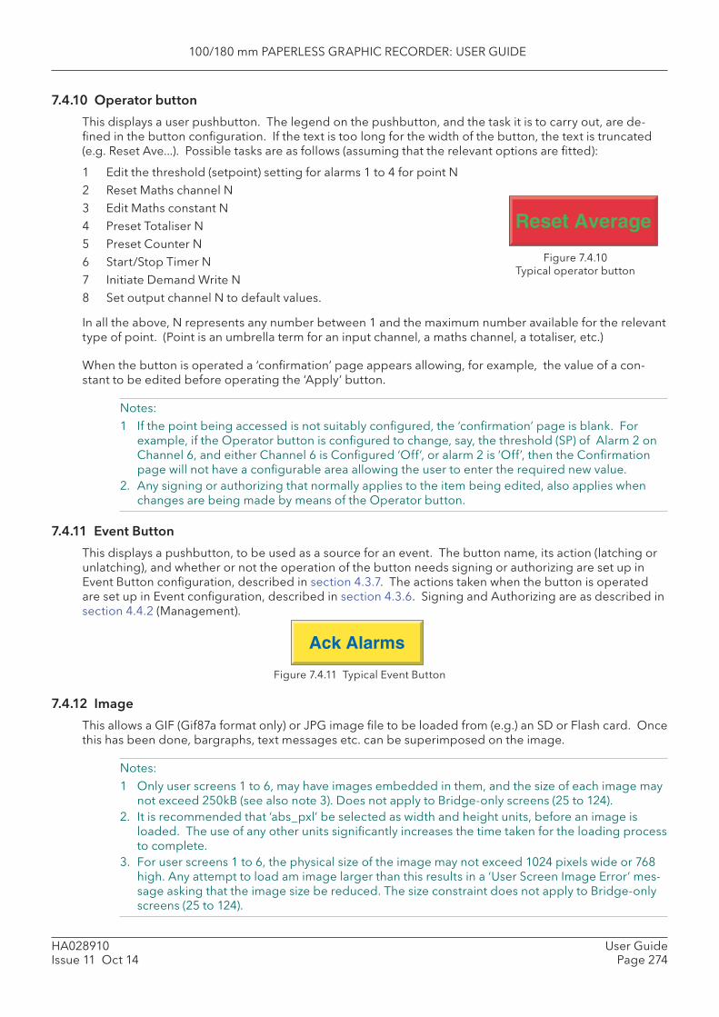
100/180 mm PAPERLESS GRAPHIC RECORDER: USER GUIDE
HA028910Issue 11 Oct 14
User GuidePage 274
7.4.10 Operator button
This displays a user pushbutton. The legend on the pushbutton, and the task it is to carry out, are de-fi ned in the button confi guration. If the text is too long for the width of the button, the text is truncated (e.g. Reset Ave...). Possible tasks are as follows (assuming that the relevant options are fi tted):
1 Edit the threshold (setpoint) setting for alarms 1 to 4 for point N2 Reset Maths channel N3 Edit Maths constant N4 Preset Totaliser N5 Preset Counter N6 Start/Stop Timer N7 Initiate Demand Write N8 Set output channel N to default values.
In all the above, N represents any number between 1 and the maximum number available for the relevant type of point. (Point is an umbrella term for an input channel, a maths channel, a totaliser, etc.)
When the button is operated a ‘confi rmation’ page appears allowing, for example, the value of a con-stant to be edited before operating the ‘Apply’ button.
Notes:1 If the point being accessed is not suitably confi gured, the ‘confi rmation’ page is blank. For
example, if the Operator button is confi gured to change, say, the threshold (SP) of Alarm 2 on Channel 6, and either Channel 6 is Confi gured ‘Off’, or alarm 2 is ‘Off’, then the Confi rmation page will not have a confi gurable area allowing the user to enter the required new value.
2. Any signing or authorizing that normally applies to the item being edited, also applies when changes are being made by means of the Operator button.
7.4.11 Event Button
This displays a pushbutton, to be used as a source for an event. The button name, its action (latching or unlatching), and whether or not the operation of the button needs signing or authorizing are set up in Event Button confi guration, described in section 4.3.7. The actions taken when the button is operated are set up in Event confi guration, described in section 4.3.6. Signing and Authorizing are as described in section 4.4.2 (Management).
Figure 7.4.11 Typical Event Button
7.4.12 Image
This allows a GIF (Gif87a format only) or JPG image fi le to be loaded from (e.g.) an SD or Flash card. Once this has been done, bargraphs, text messages etc. can be superimposed on the image.
Notes: 1 Only user screens 1 to 6, may have images embedded in them, and the size of each image may
not exceed 250kB (see also note 3). Does not apply to Bridge-only screens (25 to 124).2. It is recommended that ‘abs_pxl’ be selected as width and height units, before an image is
loaded. The use of any other units signifi cantly increases the time taken for the loading process to complete.
3. For user screens 1 to 6, the physical size of the image may not exceed 1024 pixels wide or 768 high. Any attempt to load am image larger than this results in a ‘ User Screen Image Error’ mes-sage asking that the image size be reduced. The size constraint does not apply to Bridge-only screens (25 to 124).
Reset Average
Ack Alarms
Figure 7.4.10Typical operator button
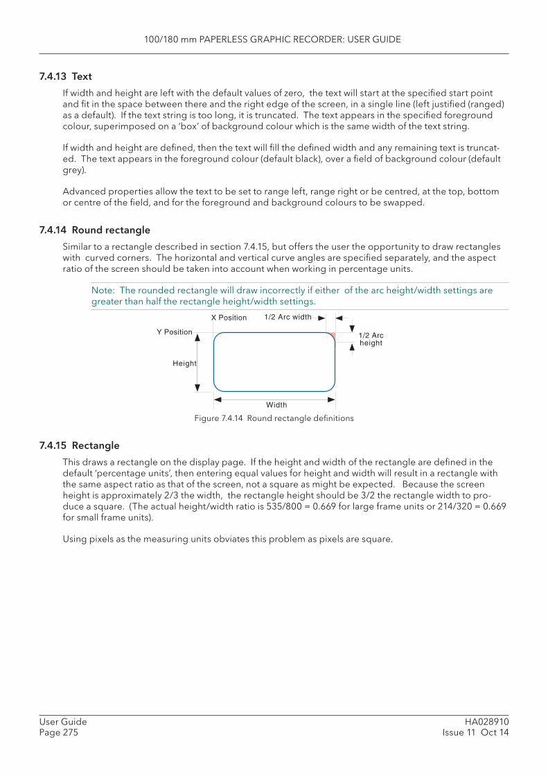
100/180 mm PAPERLESS GRAPHIC RECORDER: USER GUIDE
HA028910Issue 11 Oct 14
User GuidePage 275
7.4.13 Text
If width and height are left with the default values of zero, the text will start at the specifi ed start point and fi t in the space between there and the right edge of the screen, in a single line (left justifi ed (ranged) as a default). If the text string is too long, it is truncated. The text appears in the specifi ed foreground colour, superimposed on a ‘box’ of background colour which is the same width of the text string.
If width and height are defi ned, then the text will fi ll the defi ned width and any remaining text is truncat-ed. The text appears in the foreground colour (default black), over a fi eld of background colour (default grey).
Advanced properties allow the text to be set to range left, range right or be centred, at the top, bottom or centre of the fi eld, and for the foreground and background colours to be swapped.
7.4.14 Round rectangle
Similar to a rectangle described in section 7.4.15, but offers the user the opportunity to draw rectangles with curved corners. The horizontal and vertical curve angles are specifi ed separately, and the aspect ratio of the screen should be taken into account when working in percentage units.
Note: The rounded rectangle will draw incorrectly if either of the arc height/width settings are greater than half the rectangle height/width settings.
Figure 7.4.14 Round rectangle defi nitions
7.4.15 Rectangle
This draws a rectangle on the display page. If the height and width of the rectangle are defi ned in the default ‘percentage units’, then entering equal values for height and width will result in a rectangle with the same aspect ratio as that of the screen, not a square as might be expected. Because the screen height is approximately 2/3 the width, the rectangle height should be 3/2 the rectangle width to pro-duce a square. (The actual height/width ratio is 535/800 = 0.669 for large frame units or 214/320 = 0.669 for small frame units).
Using pixels as the measuring units obviates this problem as pixels are square.
Y Position
X Position
Width
1/2 Arc width
1/2 Archeight
Height
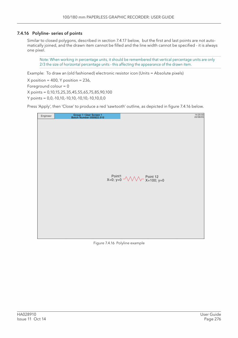
100/180 mm PAPERLESS GRAPHIC RECORDER: USER GUIDE
HA028910Issue 11 Oct 14
User GuidePage 276
7.4.16 Polyline- series of points
Similar to closed polygons, described in section 7.4.17 below, but the fi rst and last points are not auto-matically joined, and the drawn item cannot be fi lled and the line width cannot be specifi ed - it is always one pixel.
Note: When working in percentage units, it should be remembered that vertical percentage units are only 2/3 the size of horizontal percentage units - this affecting the appearance of the drawn item.
Example: To draw an (old fashioned) electronic resistor icon (Units = Absolute pixels)
X position = 400, Y position = 236, Foreground colour = 0X points = 0,10,15,25,35,45,55,65,75,85,90,100Y points = 0,0,-10,10,-10,10,-10,10,-10,10,0,0
Press ‘Apply’, then ‘Close’ to produce a red ‘sawtooth’ outline, as depicted in fi gure 7.4.16 below.
Figure 7.4.16 Polyline example
Group 1 • User Screen 1Batch Number:050822.010
14:20:5022/08/05Engineer
Point1X=0; y=0
Point 12X=100; y=0
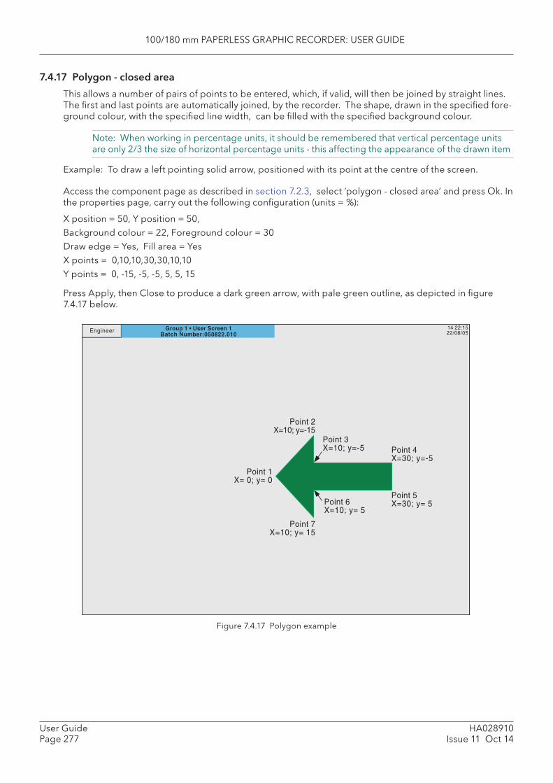
100/180 mm PAPERLESS GRAPHIC RECORDER: USER GUIDE
HA028910Issue 11 Oct 14
User GuidePage 277
7.4.17 Polygon - closed area
This allows a number of pairs of points to be entered, which, if valid, will then be joined by straight lines. The fi rst and last points are automatically joined, by the recorder. The shape, drawn in the specifi ed fore-ground colour, with the specifi ed line width, can be fi lled with the specifi ed background colour.
Note: When working in percentage units, it should be remembered that vertical percentage units are only 2/3 the size of horizontal percentage units - this affecting the appearance of the drawn item
Example: To draw a left pointing solid arrow, positioned with its point at the centre of the screen.
Access the component page as described in section 7.2.3, select ‘polygon - closed area’ and press Ok. In the properties page, carry out the following confi guration (units = %):
X position = 50, Y position = 50, Background colour = 22, Foreground colour = 30Draw edge = Yes, Fill area = YesX points = 0,10,10,30,30,10,10Y points = 0, -15, -5, -5, 5, 5, 15
Press Apply, then Close to produce a dark green arrow, with pale green outline, as depicted in fi gure 7.4.17 below.
Figure 7.4.17 Polygon example
14:22:1522/08/05
Point 1X= 0; y= 0
Point 2X=10; y=-15
Point 3X=10; y=-5 Point 4
X=30; y=-5
Point 5X=30; y= 5Point 6
X=10; y= 5
Point 7X=10; y= 15
Group 1 • User Screen 1Batch Number:050822.010
Engineer
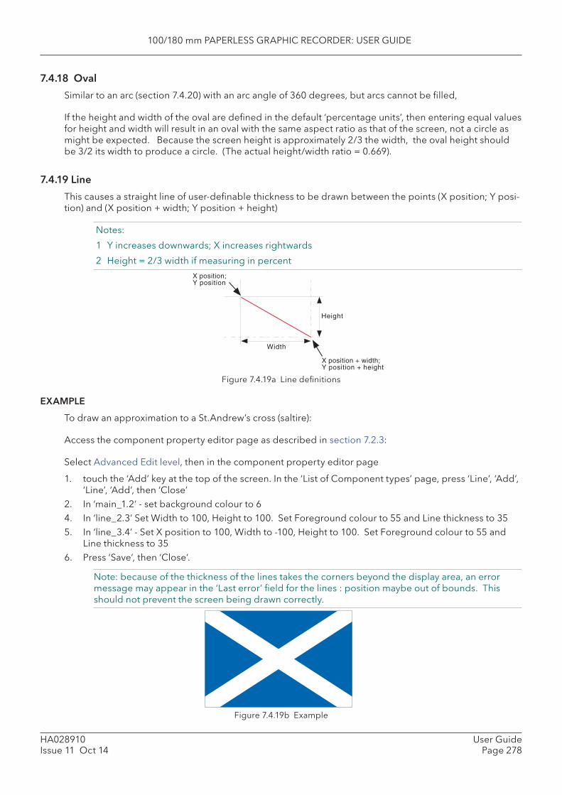
100/180 mm PAPERLESS GRAPHIC RECORDER: USER GUIDE
HA028910Issue 11 Oct 14
User GuidePage 278
7.4.18 Oval
Similar to an arc (section 7.4.20) with an arc angle of 360 degrees, but arcs cannot be fi lled,
If the height and width of the oval are defi ned in the default ‘percentage units’, then entering equal values for height and width will result in an oval with the same aspect ratio as that of the screen, not a circle as might be expected. Because the screen height is approximately 2/3 the width, the oval height should be 3/2 its width to produce a circle. (The actual height/width ratio = 0.669).
7.4.19 Line
This causes a straight line of user-defi nable thickness to be drawn between the points (X position; Y posi-tion) and (X position + width; Y position + height)
Notes:
1 Y increases downwards; X increases rightwards
2 Height = 2/3 width if measuring in percent
X position;Y position
Height
Width
X position + width;Y position + height
Figure 7.4.19a Line defi nitions
EXAMPLE
To draw an approximation to a St.Andrew’s cross (saltire):
Access the component property editor page as described in section 7.2.3:
Select Advanced Edit level, then in the component property editor page
1. touch the ‘Add’ key at the top of the screen. In the ‘List of Component types’ page, press ‘Line’, ‘Add’, ‘Line’, ‘Add’, then ‘Close’
2. In ‘main_1.2’ - set background colour to 64. In ‘line_2.3’ Set Width to 100, Height to 100. Set Foreground colour to 55 and Line thickness to 355. In ‘line_3.4’ - Set X position to 100, Width to -100, Height to 100. Set Foreground colour to 55 and
Line thickness to 356. Press ‘Save’, then ‘Close’.
Note: because of the thickness of the lines takes the corners beyond the display area, an error message may appear in the ‘Last error’ fi eld for the lines : position maybe out of bounds. This should not prevent the screen being drawn correctly.
Figure 7.4.19b Example
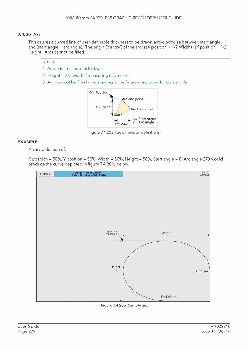
100/180 mm PAPERLESS GRAPHIC RECORDER: USER GUIDE
HA028910Issue 11 Oct 14
User GuidePage 279
7.4.20 Arc
This causes a curved line of user-defi nable thickness to be drawn anti-clockwise between start angle and (start angle + arc angle). The origin (‘centre’) of the arc is (X position + 1/2 Width) ; (Y position + 1/2 Height). Arcs cannot be fi lled.
Notes:
1 Angle increases anticlockwise
2 Height = 2/3 width if measuring in percent
3 Arcs cannot be fi lled - the shading in the fi gure is included for clarity only
Figure 7.4.20a Arc dimension defi nitions
EXAMPLE
An arc defi nition of:
X position = 50%, Y position = 50%, Width = 50%, Height = 50%, Start angle = 0; Arc angle 270 would produce the curve depicted in fi gure 7.4.20b, below.
Figure 7.4.20b Sample arc
X/Y Position
1/2 Width
1/2 HeightArc Start point
Arc end point
= Start angle= Arc angle
14:24:3122/08/05
Width
Height
X position;y position
Start of arc
End of arc
Group 1 • User Screen 1Batch Number:050822.010
Engineer
100/180 mm PAPERLESS GRAPHIC RECORDER: USER GUIDE
HA028910Issue 11 Oct 14
User GuidePage 280
7.5 MEASURING UNIT COMPARISONSNote: All the following fi gures are approximate.
7.5.1 XGA screen
The physical display screen area available for user screens is approximately 245 mm across and 164 mm high. This area can be divided into a 100 x 100 array for percentage measurement or into a pixel array, 1024 across by 700 vertically.
Thus, horizontally, 10 mm = 4% = 42 pixelsor 1% = 2.45 mm = 10.24 pixelsor 10 pixels = 2.45 mmand Vertically, 10 mm = 6% = 43 pixelsor 1% = 1.64 mm = 7 pixelsor 10 pixels = 2.3 mm
Centre of screen is given by X = 50%; Y = 50% or by X = 512 pixels; Y = 350 pixels
7.5.2 QVGA screen
The physical display screen area available for user screens is approximately 100 mm across and 72 mm high. This area can be divided into a 100 x 100 array for percentage measurement or into a pixel array, 320 across by 210 vertically.
Thus, horizontally,
10 mm = 10% = 32 pixelsor 1% = 1 mm = 3.2 pixelsor 10 pixels = 3.2 mmand Vertically, 10 mm = 13% = 29 pixelsor 1% = 0.72 mm = 2.4 pixelsor 10 pixels = 3.4 mm
Centre of screen is given by X = 50%; Y = 50% or by X = 160 pixels; Y = 105 pixels
7.6 ERROR CODESError codes 1 to F may appear at the top left corner of the screen. The following codes are currently implemented, and if more than one occurs at the same time, the code numbers are added. For example, Error code 6 would mean that codes 4 and 2 had both occurred.
1 Component error e.g. image does not exist.2 Error loading the Property.uhr fi le4 Error loading the Style.uhr fi le8 Error loading the usrscrn.uhu fi le
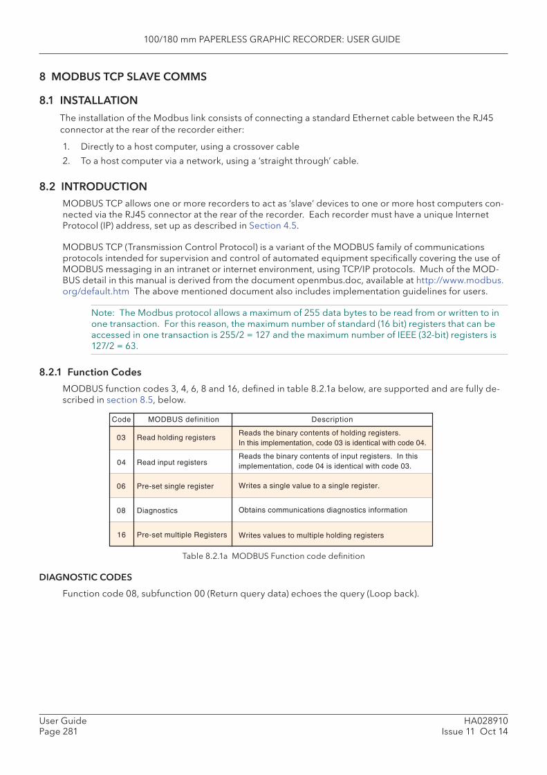
100/180 mm PAPERLESS GRAPHIC RECORDER: USER GUIDE
HA028910Issue 11 Oct 14
User GuidePage 281
8 MODBUS TCP SLAVE COMMS
8.1 INSTALLATION
The installation of the Modbus link consists of connecting a standard Ethernet cable between the RJ45 connector at the rear of the recorder either:
1. Directly to a host computer, using a crossover cable
2. To a host computer via a network, using a ‘straight through’ cable.
8.2 INTRODUCTIONMODBUS TCP allows one or more recorders to act as ‘slave’ devices to one or more host computers con-nected via the RJ45 connector at the rear of the recorder. Each recorder must have a unique Internet Protocol (IP) address, set up as described in Section 4.5.
MODBUS TCP (Transmission Control Protocol) is a variant of the MODBUS family of communications protocols intended for supervision and control of automated equipment specifi cally covering the use of MODBUS messaging in an intranet or internet environment, using TCP/IP protocols. Much of the MOD-BUS detail in this manual is derived from the document openmbus.doc, available at http://www.modbus.org/default.htm The above mentioned document also includes implementation guidelines for users.
Note: The Modbus protocol allows a maximum of 255 data bytes to be read from or written to in one transaction. For this reason, the maximum number of standard (16 bit) registers that can be accessed in one transaction is 255/2 = 127 and the maximum number of IEEE (32-bit) registers is 127/2 = 63.
8.2.1 Function Codes
MODBUS function codes 3, 4, 6, 8 and 16, defi ned in table 8.2.1a below, are supported and are fully de-scribed in section 8.5, below.
Table 8.2.1a MODBUS Function code defi nition
DIAGNOSTIC CODES
Function code 08, subfunction 00 (Return query data) echoes the query (Loop back).
Reads the binary contents of holding registers.In this implementation, code 03 is identical with code 04.
Read holding registers
Read input registers
Pre-set single register
Diagnostics
Pre-set multiple Registers
Reads the binary contents of input registers. In thisimplementation, code 04 is identical with code 03.
Writes a single value to a single register.
Obtains communications diagnostics information
Writes values to multiple holding registers
03
04
06
08
16
Code MODBUS definition Description
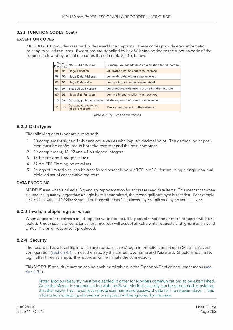
100/180 mm PAPERLESS GRAPHIC RECORDER: USER GUIDE
HA028910Issue 11 Oct 14
User GuidePage 282
An invalid function code was receivedIllegal Function01
Illegal Data Value
Slave Device Failure
Gateway path unavailable
Gateway target devicefailed to respond
An invalid data value was received
An unrecoverable error occurred in the recorder
Gateway misconfigured or overloaded.
Device not present on the network
03
04
0A
0B
CodeMODBUS definition Description (see Modbus specification for full details)
An invalid data address was receivedIllegal Data Address02
HexDec
01
02
03
04
10
11
Illegal Sub Function An invalid sub function was received.0909
8.2.1 FUNCTION CODES (Cont.)
EXCEPTION CODES
MODBUS TCP provides reserved codes used for exceptions. These codes provide error information relating to failed requests. Exceptions are signalled by hex 80 being added to the function code of the request, followed by one of the codes listed in table 8.2.1b, below.
Table 8.2.1b Exception codes
8.2.2 Data types
The following data types are supported:
1 2’s complement signed 16-bit analogue values with implied decimal point. The decimal point posi-tion must be confi gured in both the recorder and the host computer.
2 2’s complement, 16, 32 and 64 bit signed integers.
3 16-bit unsigned integer values.
4 32 bit IEEE Floating point values.
5 Strings of limited size, can be transferred across Modbus TCP in ASCII format using a single non-mul-tiplexed set of consecutive registers.
DATA ENCODING
MODBUS uses what is called a ‘Big endian’ representation for addresses and data items. This means that when a numerical quantity larger than a single byte is transmitted, the most signifi cant byte is sent fi rst. For example a 32-bit hex value of 12345678 would be transmitted as 12, followed by 34, followed by 56 and fi nally 78.
8.2.3 Invalid multiple register writes
When a recorder receives a multi-register write request, it is possible that one or more requests will be re-jected. Under such a circumstance, the recorder will accept all valid write requests and ignore any invalid writes. No error response is produced.
8.2.4 Security
The recorder has a local fi le in which are stored all users’ login information, as set up in Security/Access confi guration (section 4.4) it must then supply the correct Username and Password. Should a host fail to login after three attempts, the recorder will terminate the connection.
This MODBUS security function can be enabled/disabled in the Operator/Confi g/Instrument menu (sec-tion 4.3.1).
Note: Modbus Security must be disabled in order for Modbus communications to be established. Once the Master is communicating with the Slave, Modbus security can be re-enabled, providing that the master has the correct remote user name and password data for the relevant slave. If this information is missing, all read/write requests will be ignored by the slave.

100/180 mm PAPERLESS GRAPHIC RECORDER: USER GUIDE
HA028910Issue 11 Oct 14
User GuidePage 283
(Continued)
8.2.4 SECURITY (Cont.)
The following C++ code is intended for use in creating a suitable 16-bit encrypted register using an IP ad-dress and password:
/*--------------------------------------------------------------------------- FUNCTION : MB_Driver::encrypt DESCRIPTION : Create an encrypted value from a password string ARGUMENTS : pswd : Pointer to password from network fi le eKey : Pointer to eKey, usually I.P. address (must be 4 bytes) RETURN : result : A 16 bit value representing the encryption result NOTES : None---------------------------------------------------------------------------*/Ushort MB_Driver::encrypt(cchar *pswd, cchar *ipAddr){ Uchar key1; Uchar key2; Ushort dataLen; Uchar ibyte; Ushort byteResult = 0; Uchar *encryptedData = NULL; Uchar eKeys[4]; Ulong ipAddress; /* Convert ip address to an unsigned long value so that we can manipulate each of the 4 bytes, to be used as our private keys */ ipAddress = inet_addr(ipAddr); // Now split the bytes up by copying the IP address into a byte array memcpy(eKeys, &ipAddress, sizeof(Ulong)); // From the 4 bytes of the IP address create two exclusive keys key1 = eKeys[0] ^ eKeys[3]; key2 = eKeys[1] ^ eKeys[2]; // Calculate the length of the string to be encrypted dataLen = strlen(pswd); // Create some memory to store the new encrypted password encryptedData = (Uchar*) malloc(sizeof(Uchar)*dataLen); /* Copy the unencrypted password into a byte array, so we can use the character code as each byte value */ memcpy(encryptedData, pswd, dataLen); /* Perform EXOR comparison between keys and raw data. Perform the operation on each byte using alternate key values starting at byte 1 with key 1 */ for(ibyte=0; ibyte < dataLen;) { // EXOR with the key1 encryptedData[ibyte++] ^= key1;
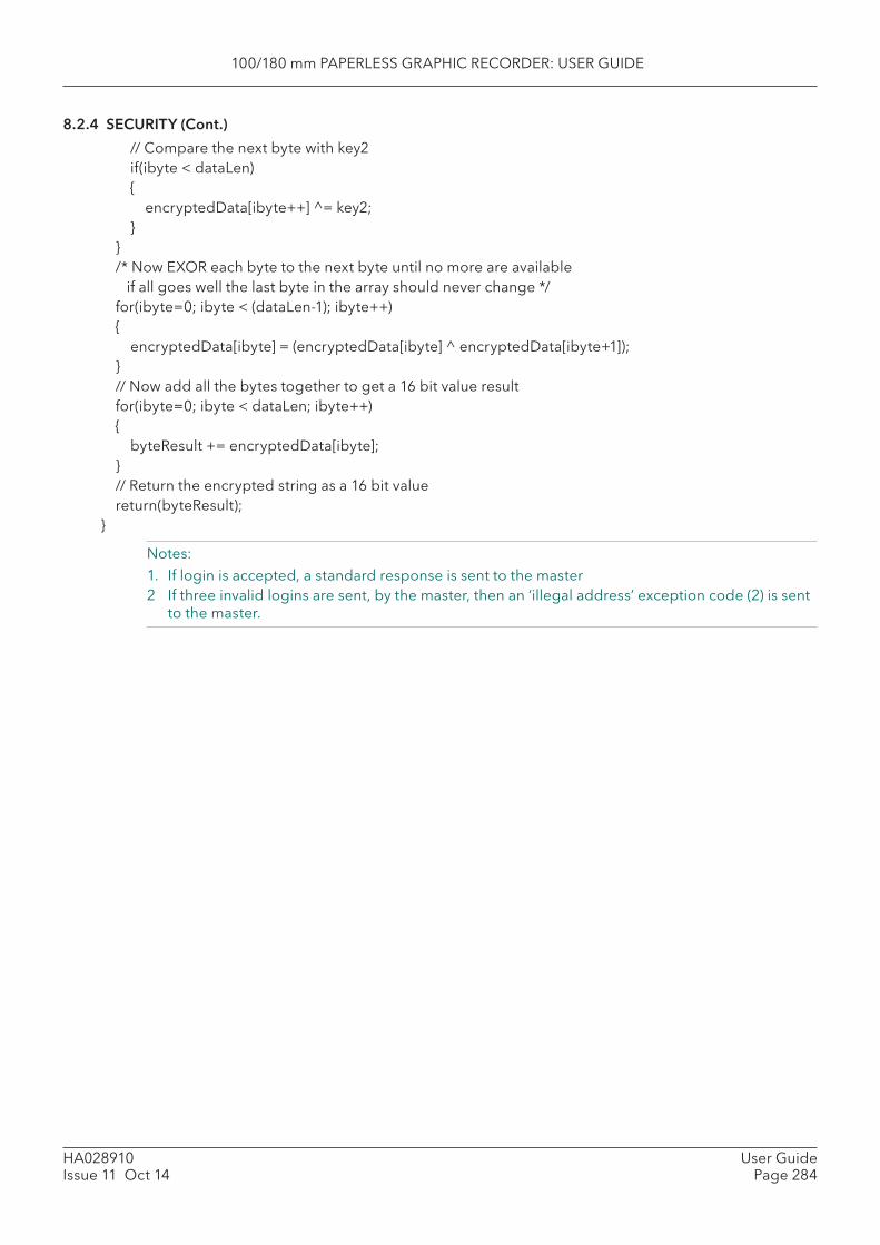
100/180 mm PAPERLESS GRAPHIC RECORDER: USER GUIDE
HA028910Issue 11 Oct 14
User GuidePage 284
8.2.4 SECURITY (Cont.)
// Compare the next byte with key2 if(ibyte < dataLen) { encryptedData[ibyte++] ^= key2; } } /* Now EXOR each byte to the next byte until no more are available if all goes well the last byte in the array should never change */ for(ibyte=0; ibyte < (dataLen-1); ibyte++) { encryptedData[ibyte] = (encryptedData[ibyte] ^ encryptedData[ibyte+1]); } // Now add all the bytes together to get a 16 bit value result for(ibyte=0; ibyte < dataLen; ibyte++) { byteResult += encryptedData[ibyte]; } // Return the encrypted string as a 16 bit value return(byteResult);}
Notes:1. If login is accepted, a standard response is sent to the master2 If three invalid logins are sent, by the master, then an ‘illegal address’ exception code (2) is sent
to the master.
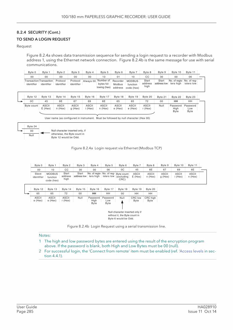
100/180 mm PAPERLESS GRAPHIC RECORDER: USER GUIDE
HA028910Issue 11 Oct 14
User GuidePage 285
Byte 0
Transactionidentifier
Transactionidentifier
Protocolidentifier
Protocolidentifier
Byte 1 Byte 2 Byte 3 Byte 4
Number ofbytes fol-
lowing (hex)
Byte 5
Always 00
Byte 6
RecorderModbusaddress
Byte 7
MODBUSfunction
code (hex)
00 00 00 00 00 13 01
Byte 8 Byte 9 Byte 10 Byte 11
Byte 12 Byte 13 Byte 14 Byte 15 Byte 16 Byte 17 Byte 18 Byte 19 Byte 20 Byte 21 Byte 22 Byte 23
10 CC
Startaddress
high
Startaddress low
No. of regis-ters high
No. of reg-isters low
Byte count
30
ASCIIE (Hex)
45
Null PasswordHighByte
0C
00 06
ASCIIn (Hex)
6E
ASCIIg (Hex)
67
ASCIIi (Hex)
69
ASCIIn (Hex)
6E
ASCIIe (Hex)
65
ASCIIe (Hex)
65
ASCIIr (Hex)
72 00 HH
User name (as configured in instrument. Must be followed by null character (Hex 00)
Byte 24
Null
00
PasswordLowByte
HH HH
Null character inserted only, ifotherwise, the Byte count inByte 12 would be Odd.
Byte 6
Slaveidentifier
MODBUSfunction
code (hex)
00
Byte 0 Byte 1 Byte 2 Byte 3 Byte 4 Byte 5
10 CC
Startaddress
high
Startaddress low
No. of regis-ters high
No. of reg-isters low
30 00 06
Byte 7 Byte 8 Byte 9 Byte 10 Byte 11
Byte 12 Byte 13 Byte 14 Byte 15 Byte 16 Byte 17 Byte 18 Byte 19 Byte 20
Byte count(excluding
CRC)
ASCIIE (Hex)
450C
ASCIIn (Hex)
6E
ASCIIg (Hex)
67
ASCIIi (Hex)
69
ASCIIn (Hex)
6E
Null PasswordHighByte
ASCIIe (Hex)
65
ASCIIe (Hex)
65
ASCIIr (Hex)
72 00 HH
Null
00
PasswordLowByte
HH HH
Null character inserted only ifwithout it, the Byte count inByte 6 would be Odd.
CRC lowByte
HH HH
CRC highByte
8.2.4 SECURITY (Cont.)
TO SEND A LOGIN REQUEST
Request
Figure 8.2.4a shows data transmission sequence for sending a login request to a recorder with Modbus address 1, using the Ethernet network connection. Figure 8.2.4b is the same message for use with serial communications.
Figure 8.2.4a Login request via Ethernet (Modbus TCP)
Figure 8.2.4b Login Request using a serial transmission line.
Notes:1 The high and low password bytes are entered using the result of the encryption program
above. If the password is blank, both High and Low Bytes must be 00 (null).2 For successful login, the ‘Connect from remote’ item must be enabled (ref. ‘Access levels in sec-
tion 4.4.1).
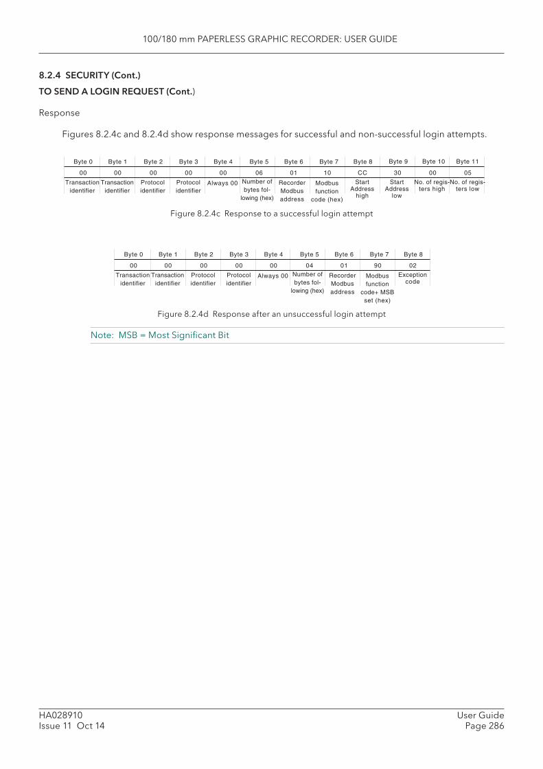
100/180 mm PAPERLESS GRAPHIC RECORDER: USER GUIDE
HA028910Issue 11 Oct 14
User GuidePage 286
Byte 0
Transactionidentifier
Transactionidentifier
Protocolidentifier
Protocolidentifier
Byte 1 Byte 2 Byte 3 Byte 4
Number ofbytes fol-
lowing (hex)
Byte 5
Always 00
Byte 6
RecorderModbusaddress
Byte 7
Modbusfunction
code (hex)
00 00 00 00 00 06 01
Byte 8
StartAddress
high
Byte 9 Byte 10 Byte 11
10
StartAddress
low
No. of regis-ters high
No. of regis-ters low
CC 30 00 05
Byte 0
Transactionidentifier
Transactionidentifier
Protocolidentifier
Protocolidentifier
Byte 1 Byte 2 Byte 3 Byte 4
Number ofbytes fol-
lowing (hex)
Byte 5
Always 00
Byte 6
RecorderModbusaddress
Byte 7
Modbusfunction
code+ MSBset (hex)
00 00 00 00 00 04 01
Byte 8
Exceptioncode
90 02
8.2.4 SECURITY (Cont.)
TO SEND A LOGIN REQUEST (Cont.)
Response
Figures 8.2.4c and 8.2.4d show response messages for successful and non-successful login attempts.
Figure 8.2.4c Response to a successful login attempt
Figure 8.2.4d Response after an unsuccessful login attempt
Note: MSB = Most Signifi cant Bit
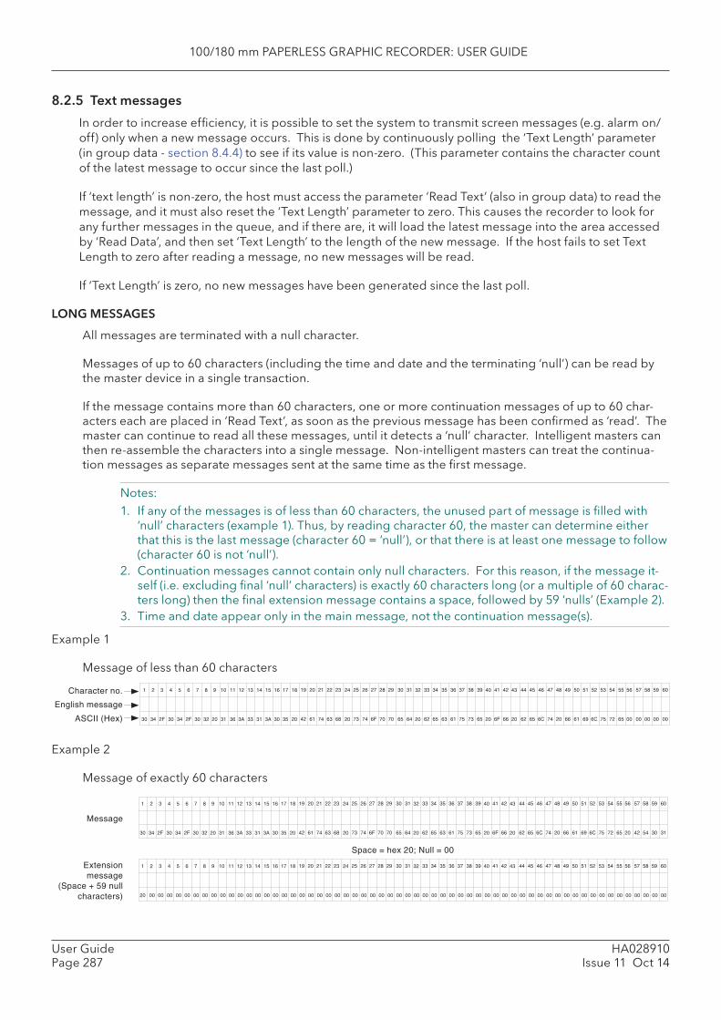
100/180 mm PAPERLESS GRAPHIC RECORDER: USER GUIDE
HA028910Issue 11 Oct 14
User GuidePage 287
19 20 21 22 23 25 26 27 28 29 30 31 33 34 35 36 37 38 39 41 42 44 45 46 47 49 50 51 52 53 54 551 2 3 4 5 6 7 8 10 11 12 13 14 15 16 179 18 24 32 40 43 48 56 57 58 59 60
42 61 74 63 68 73 74 6F 70 70 65 64 62 65 63 61 75 73 65 6F 66 62 65 6C 74 66 61 69 6C 75 72 6530 34 2F 30 34 2F 30 32 31 36 3A 33 31 3A 30 3520 20 20 20 20 20 20 20 42 54 30 31
19 20 21 22 23 25 26 27 28 29 30 31 33 34 35 36 37 38 39 41 42 44 45 46 47 49 50 51 52 53 54 551 2 3 4 5 6 7 8 10 11 12 13 14 15 16 179 18 24 32 40 43 48 56 57 58 59 60
20 00 00 00 00 00 00 00 00 00 00 00 00 00 00 00 00 00 00 00 00 00 00 00 00 00 00 00 00 00 00 00 00 00 00 00 00 00 00 00 00 00 00 00 00 00 00 00 00 00 00 00 00 00 00 00 00 00 00 00
Message
Extensionmessage
(Space + 59 nullcharacters)
Space = hex 20; Null = 00
19 20 21 22 23 25 26 27 28 29 30 31 33 34 35 36 37 38 39 41 42 44 45 46 47 49 50 51 52 53 54 551 2 3 4 5 6 7 8 10 11 12 13 14 15 16 179 18 24 32 40 43 48 56 57 58 59 60
42 61 74 63 68 73 74 6F 70 70 65 64 62 65 63 61 75 73 65 6F 66 62 65 6C 74 66 61 69 6C 75 72 6530 34 2F 30 34 2F 30 32 31 36 3A 33 31 3A 30 3520 20 20 20 20 20 20 00 00 00 00 00
Character no.
English message
ASCII (Hex)
8.2.5 Text messages
In order to increase effi ciency, it is possible to set the system to transmit screen messages (e.g. alarm on/off) only when a new message occurs. This is done by continuously polling the ‘Text Length’ parameter (in group data - section 8.4.4) to see if its value is non-zero. (This parameter contains the character count of the latest message to occur since the last poll.)
If ‘text length’ is non-zero, the host must access the parameter ‘Read Text’ (also in group data) to read the message, and it must also reset the ‘Text Length’ parameter to zero. This causes the recorder to look for any further messages in the queue, and if there are, it will load the latest message into the area accessed by ‘Read Data’, and then set ‘Text Length’ to the length of the new message. If the host fails to set Text Length to zero after reading a message, no new messages will be read.
If ‘Text Length’ is zero, no new messages have been generated since the last poll.
LONG MESSAGES
All messages are terminated with a null character.
Messages of up to 60 characters (including the time and date and the terminating ‘null’) can be read by the master device in a single transaction.
If the message contains more than 60 characters, one or more continuation messages of up to 60 char-acters each are placed in ‘Read Text’, as soon as the previous message has been confi rmed as ‘read’. The master can continue to read all these messages, until it detects a ‘null’ character. Intelligent masters can then re-assemble the characters into a single message. Non-intelligent masters can treat the continua-tion messages as separate messages sent at the same time as the fi rst message.
Notes:1. If any of the messages is of less than 60 characters, the unused part of message is fi lled with
‘null’ characters (example 1). Thus, by reading character 60, the master can determine either that this is the last message (character 60 = ‘null’), or that there is at least one message to follow (character 60 is not ‘null’).
2. Continuation messages cannot contain only null characters. For this reason, if the message it-self (i.e. excluding fi nal ‘null’ characters) is exactly 60 characters long (or a multiple of 60 charac-ters long) then the fi nal extension message contains a space, followed by 59 ‘nulls’ (Example 2).
3. Time and date appear only in the main message, not the continuation message(s).
Example 1
Message of less than 60 characters
Example 2
Message of exactly 60 characters

100/180 mm PAPERLESS GRAPHIC RECORDER: USER GUIDE
HA028910Issue 11 Oct 14
User GuidePage 288
19 20 21 22 23 25 26 27 28 29 30 31 33 34 35 36 37 38 39 41 42 44 45 46 47 49 50 51 52 53 54 551 2 3 4 5 6 7 8 10 11 12 13 14 15 16 179 18 24 32 40 43 48 56 57 58 59 60
42 61 74 63 68 73 74 6F 70 70 65 64 62 65 63 61 75 73 65 6F 66 62 65 6C 74 66 61 69 6C 75 72 6530 34 2F 30 34 2F 30 32 31 36 3A 33 31 3A 30 3520 20 20 20 20 20 20 20 6F 6E 20 6C
19 20 21 22 23 25 26 27 28 29 30 31 33 34 35 36 37 38 39 41 42 44 45 46 47 49 50 51 52 53 54 551 2 3 4 5 6 7 8 10 11 12 13 14 15 16 179 18 24 32 40 43 48 56 57 58 59 60
69 6E 65 20 33 20 73 65 63 74 69 6F 6E 20 31 37 00 00 00 00 00 00 00 00 00 00 00 00 00 00 00 00 00 00 00 00 00 00 00 00 00 00 00 00 00 00 00 00 00 00 00 00 00 00 00 00 00 00 00 00
Message
Extensionmessage
Space = hex 20; Null = 00
8.2.5 TEXT MESSAGES (Cont.)
Example 3
Message of more than 60 but less than 120 characters
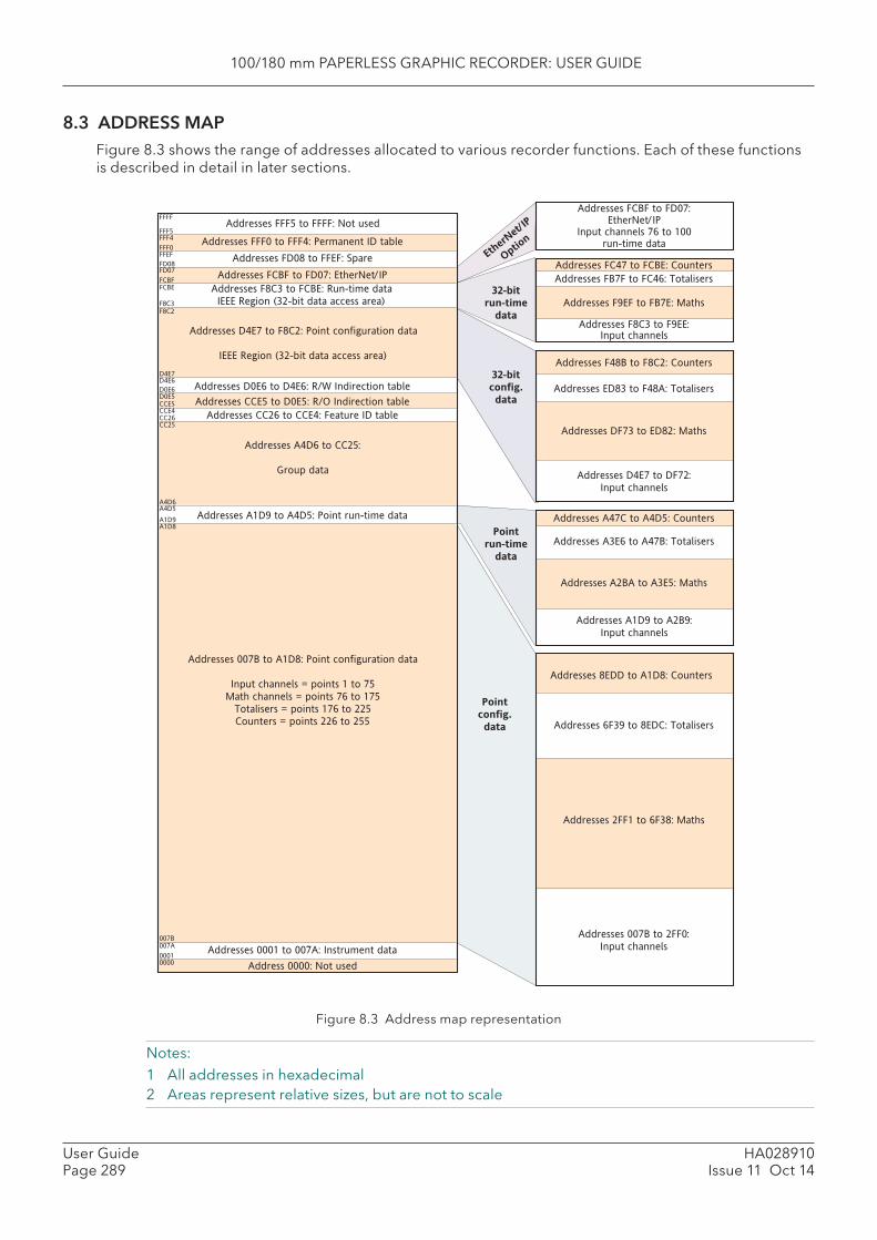
100/180 mm PAPERLESS GRAPHIC RECORDER: USER GUIDE
HA028910Issue 11 Oct 14
User GuidePage 289
8.3 ADDRESS MAPFigure 8.3 shows the range of addresses allocated to various recorder functions. Each of these functions is described in detail in later sections.
Figure 8.3 Address map representation
Notes:1 All addresses in hexadecimal2 Areas represent relative sizes, but are not to scale
16
Addresses FFF0 to FFF4: Permanent ID table
Addresses FFF5 to FFFF: Not used
Addresses FD08 to FFEF: Spare
Addresses D4E7 to F8C2: Point configuration data
IEEE Region (32-bit data access area)
Addresses D0E6 to D4E6: R/W Indirection table
Addresses CCE5 to D0E5: R/O Indirection table
Addresses CC26 to CCE4: Feature ID table
Addresses A4D6 to CC25:
Group data
Addresses A1D9 to A4D5: Point run-time data
Addresses 007B to A1D8: Point configuration data
Input channels = points 1 to 75
Math channels = points 76 to 175
Totalisers = points 176 to 225
Counters = points 226 to 255
Addresses 0001 to 007A: Instrument data
Address 0000: Not used00000001
007A
007B
A1D8A1D9
A4D5A4D6
CC25CC26CCE4CCE5
D0E5D0E6
D4E6D4E7
FCBEFCBF
FFEFFFF0
FFF4FFF5
FFFF
Addresses F8C3 to FCBE: Run-time data
IEEE Region (32-bit data access area)F8C3
F8C2
FD08FD07
Addresses FCBF to FD07: EtherNet/IP
Point
run-time
data
Point
config.
data
32-bit
run-time
data
32-bit
config.
data
Ethe
rNet
/IP
Opt
ion
Addresses FC47 to FCBE: Counters
Addresses FB7F to FC46: Totalisers
Addresses F9EF to FB7E: Maths
Addresses F8C3 to F9EE:
Input channels
Addresses F48B to F8C2: Counters
Addresses ED83 to F48A: Totalisers
Addresses DF73 to ED82: Maths
Addresses D4E7 to DF72:
Input channels
Addresses A47C to A4D5: Counters
Addresses A3E6 to A47B: Totalisers
Addresses A2BA to A3E5: Maths
Addresses A1D9 to A2B9:
Input channels
Addresses 8EDD to A1D8: Counters
Addresses 6F39 to 8EDC: Totalisers
Addresses 2FF1 to 6F38: Maths
Addresses 007B to 2FF0:
Input channels
Addresses FCBF to FD07:
EtherNet/IP
Input channels 76 to 100
run-time data
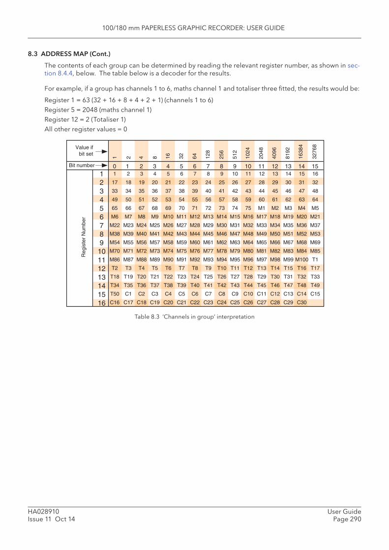
100/180 mm PAPERLESS GRAPHIC RECORDER: USER GUIDE
HA028910Issue 11 Oct 14
User GuidePage 290
123456789
10111213141516
1 2 4 8 16 32 64 128
256
512
1024
2048
4096
8192
1638
4
3276
8Value ifbit set
Bit number
Reg
iste
r N
umbe
r
1 2 3 4 5 6 7 8 9 10 11 12 13 14 15 16
17 18 19 20 21 22 23 24 25 26 27 28 29 30 31 32
33 34 35 36 37 38 39 40 41 42 43 44 45 46 47 48
49 50 51 52 53 54 55 56 57 58 59 60 61 62 63 64
65 66 67 68 69 70 71 72 73 74 75 M1 M2 M3 M4 M5
M6 M7 M8 M9 M10 M11 M12 M13 M14 M15 M16 M17 M18 M19 M20 M21
M22 M23 M24 M25 M26 M27 M28 M29 M30 M31 M32 M33 M34 M35 M36 M37
M38 M39 M40 M41 M42 M43 M44 M45 M46 M47 M48 M49 M50 M51 M52 M53
M54 M55 M56 M57 M58 M59 M60 M61 M62 M63 M64 M65 M66 M67 M68 M69
M70 M71 M72 M73 M74 M75 M76 M77 M78 M79 M80 M81 M82 M83 M84 M85
M86 M87 M88 M89 M90 M91 M92 M93 M94 M95 M96 M97 M98 M99 M100 T1
T2 T3 T4 T5 T6 T7 T8 T9 T10 T11 T12 T13 T14 T15 T16 T17
T18 T19 T20 T21 T22 T23 T24 T25 T26 T27 T28 T29 T30 T31 T32 T33
T34 T35 T36 T37 T38 T39 T40 T41 T42 T43 T44 T45 T46 T47 T48 T49
T50 C1 C2 C3 C4 C5 C6 C7 C8 C9 C10 C11 C12 C13 C14 C15
C16 C17 C18 C19 C20 C21 C22 C23 C24 C25 C26 C27 C28 C29 C30
0 1 2 3 4 5 6 7 8 9 10 11 12 13 14 15
8.3 ADDRESS MAP (Cont.)
The contents of each group can be determined by reading the relevant register number, as shown in sec-tion 8.4.4, below. The table below is a decoder for the results.
For example, if a group has channels 1 to 6, maths channel 1 and totaliser three fi tted, the results would be:
Register 1 = 63 (32 + 16 + 8 + 4 + 2 + 1) (channels 1 to 6)Register 5 = 2048 (maths channel 1)Register 12 = 2 (Totaliser 1)All other register values = 0
Table 8.3 ‘Channels in group’ interpretation
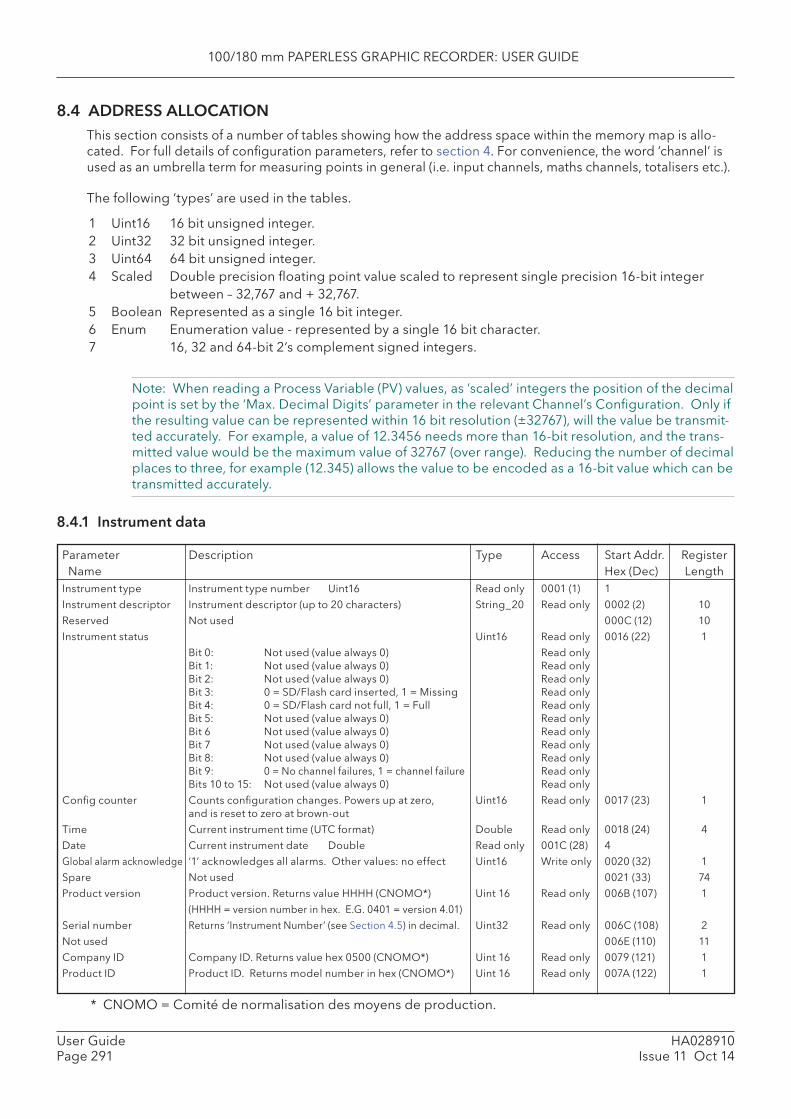
100/180 mm PAPERLESS GRAPHIC RECORDER: USER GUIDE
HA028910Issue 11 Oct 14
User GuidePage 291
* CNOMO = Comité de normalisation des moyens de production.
8.4 ADDRESS ALLOCATION This section consists of a number of tables showing how the address space within the memory map is allo-cated. For full details of confi guration parameters, refer to section 4. For convenience, the word ‘channel’ is used as an umbrella term for measuring points in general (i.e. input channels, maths channels, totalisers etc.).
The following ‘types’ are used in the tables.
1 Uint16 16 bit unsigned integer.2 Uint32 32 bit unsigned integer.3 Uint64 64 bit unsigned integer.4 Scaled Double precision fl oating point value scaled to represent single precision 16-bit integer
between – 32,767 and + 32,767.5 Boolean Represented as a single 16 bit integer.6 Enum Enumeration value - represented by a single 16 bit character.7 16, 32 and 64-bit 2’s complement signed integers.
Note: When reading a Process Variable (PV) values, as ‘scaled’ integers the position of the decimal point is set by the ‘Max. Decimal Digits’ parameter in the relevant Channel’s Confi guration. Only if the resulting value can be represented within 16 bit resolution (±32767), will the value be transmit-ted accurately. For example, a value of 12.3456 needs more than 16-bit resolution, and the trans-mitted value would be the maximum value of 32767 (over range). Reducing the number of decimal places to three, for example (12.345) allows the value to be encoded as a 16-bit value which can be transmitted accurately.
8.4.1 Instrument data
Parameter Description Type Access Start Addr. Register Name Hex (Dec) LengthInstrument type Instrument type number Uint16 Read only 0001 (1) 1
Instrument descriptor Instrument descriptor (up to 20 characters) String_20 Read only 0002 (2) 10
Reserved Not used 000C (12) 10
Instrument status Uint16 Read only 0016 (22) 1
Bit 0: Not used (value always 0) Read onlyBit 1: Not used (value always 0) Read onlyBit 2: Not used (value always 0) Read onlyBit 3: 0 = SD/Flash card inserted, 1 = Missing Read onlyBit 4: 0 = SD/Flash card not full, 1 = Full Read onlyBit 5: Not used (value always 0) Read onlyBit 6 Not used (value always 0) Read onlyBit 7 Not used (value always 0) Read onlyBit 8: Not used (value always 0) Read onlyBit 9: 0 = No channel failures, 1 = channel failure Read onlyBits 10 to 15: Not used (value always 0) Read only
Confi g counter Counts confi guration changes. Powers up at zero, Uint16 Read only 0017 (23) 1and is reset to zero at brown-out
Time Current instrument time (UTC format) Double Read only 0018 (24) 4
Date Current instrument date Double Read only 001C (28) 4
Global alarm acknowledge ‘1’ acknowledges all alarms. Other values: no effect Uint16 Write only 0020 (32) 1
Spare Not used 0021 (33) 74
Product version Product version. Returns value HHHH (CNOMO*) Uint 16 Read only 006B (107) 1
(HHHH = version number in hex. E.G. 0401 = version 4.01)
Serial number Returns ‘Instrument Number’ (see Section 4.5) in decimal. Uint32 Read only 006C (108) 2
Not used 006E (110) 11
Company ID Company ID. Returns value hex 0500 (CNOMO*) Uint 16 Read only 0079 (121) 1
Product ID Product ID. Returns model number in hex (CNOMO*) Uint 16 Read only 007A (122) 1
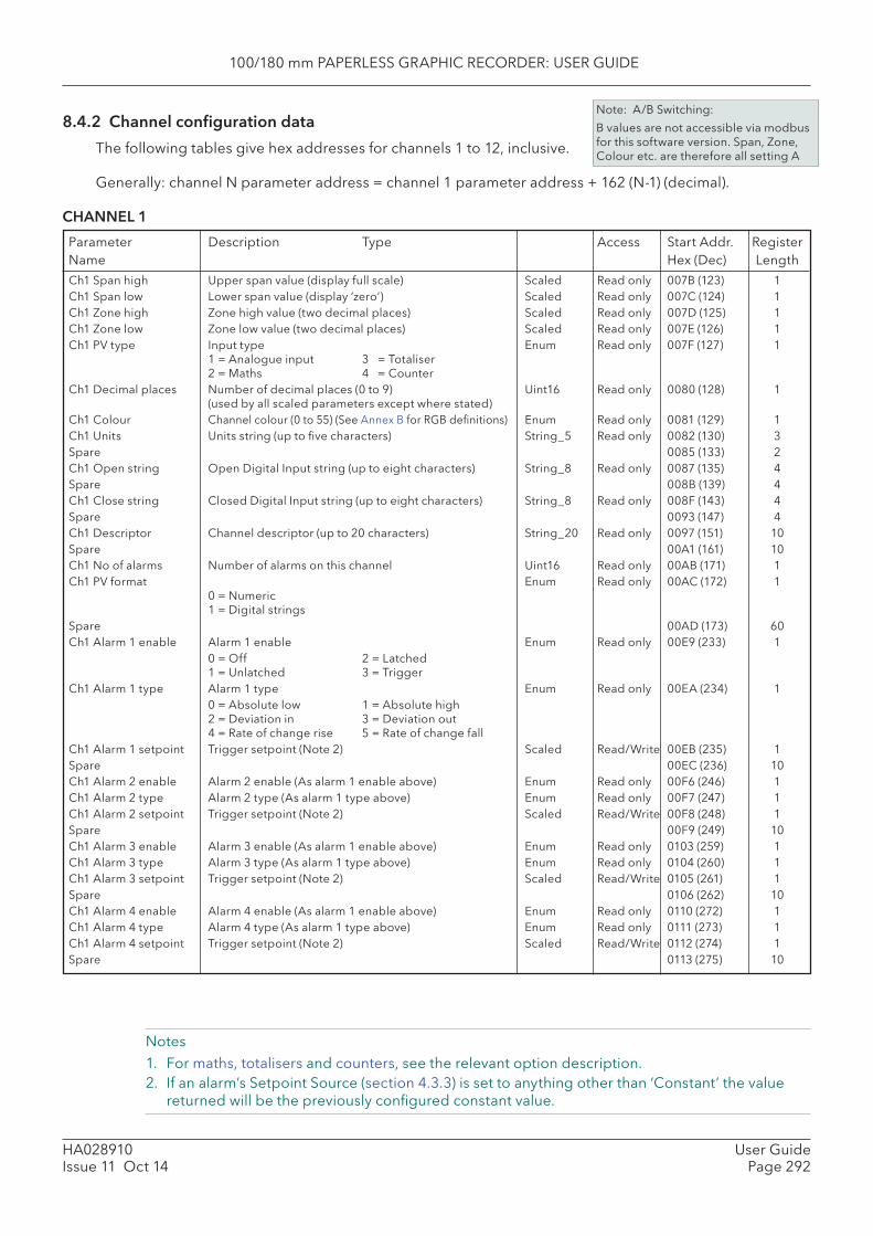
100/180 mm PAPERLESS GRAPHIC RECORDER: USER GUIDE
HA028910Issue 11 Oct 14
User GuidePage 292
8.4.2 Channel confi guration data
The following tables give hex addresses for channels 1 to 12, inclusive.
Generally: channel N parameter address = channel 1 parameter address + 162 (N-1) (decimal).
CHANNEL 1
Parameter Description Type Access Start Addr. RegisterName Hex (Dec) Length
Notes1. For maths, totalisers and counters, see the relevant option description.2. If an alarm’s Setpoint Source (section 4.3.3) is set to anything other than ‘Constant’ the value
returned will be the previously confi gured constant value.
Note: A/B Switching:
B values are not accessible via modbus for this software version. Span, Zone, Colour etc. are therefore all setting A
Ch1 Span high Upper span value (display full scale) Scaled Read only 007B (123) 1Ch1 Span low Lower span value (display ‘zero’) Scaled Read only 007C (124) 1Ch1 Zone high Zone high value (two decimal places) Scaled Read only 007D (125) 1Ch1 Zone low Zone low value (two decimal places) Scaled Read only 007E (126) 1Ch1 PV type Input type Enum Read only 007F (127) 1
1 = Analogue input 3 = Totaliser2 = Maths 4 = Counter
Ch1 Decimal places Number of decimal places (0 to 9) Uint16 Read only 0080 (128) 1(used by all scaled parameters except where stated)
Ch1 Colour Channel colour (0 to 55) (See Annex B for RGB defi nitions) Enum Read only 0081 (129) 1Ch1 Units Units string (up to fi ve characters) String_5 Read only 0082 (130) 3Spare 0085 (133) 2Ch1 Open string Open Digital Input string (up to eight characters) String_8 Read only 0087 (135) 4Spare 008B (139) 4Ch1 Close string Closed Digital Input string (up to eight characters) String_8 Read only 008F (143) 4Spare 0093 (147) 4Ch1 Descriptor Channel descriptor (up to 20 characters) String_20 Read only 0097 (151) 10Spare 00A1 (161) 10Ch1 No of alarms Number of alarms on this channel Uint16 Read only 00AB (171) 1Ch1 PV format Enum Read only 00AC (172) 1
0 = Numeric1 = Digital strings
Spare 00AD (173) 60Ch1 Alarm 1 enable Alarm 1 enable Enum Read only 00E9 (233) 1 0 = Off 2 = Latched
1 = Unlatched 3 = Trigger Ch1 Alarm 1 type Alarm 1 type Enum Read only 00EA (234) 1 0 = Absolute low 1 = Absolute high
2 = Deviation in 3 = Deviation out4 = Rate of change rise 5 = Rate of change fall
Ch1 Alarm 1 setpoint Trigger setpoint (Note 2) Scaled Read/Write 00EB (235) 1Spare 00EC (236) 10Ch1 Alarm 2 enable Alarm 2 enable (As alarm 1 enable above) Enum Read only 00F6 (246) 1Ch1 Alarm 2 type Alarm 2 type (As alarm 1 type above) Enum Read only 00F7 (247) 1Ch1 Alarm 2 setpoint Trigger setpoint (Note 2) Scaled Read/Write 00F8 (248) 1Spare 00F9 (249) 10Ch1 Alarm 3 enable Alarm 3 enable (As alarm 1 enable above) Enum Read only 0103 (259) 1Ch1 Alarm 3 type Alarm 3 type (As alarm 1 type above) Enum Read only 0104 (260) 1Ch1 Alarm 3 setpoint Trigger setpoint (Note 2) Scaled Read/Write 0105 (261) 1Spare 0106 (262) 10Ch1 Alarm 4 enable Alarm 4 enable (As alarm 1 enable above) Enum Read only 0110 (272) 1Ch1 Alarm 4 type Alarm 4 type (As alarm 1 type above) Enum Read only 0111 (273) 1Ch1 Alarm 4 setpoint Trigger setpoint (Note 2) Scaled Read/Write 0112 (274) 1Spare 0113 (275) 10
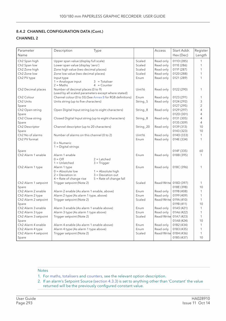
100/180 mm PAPERLESS GRAPHIC RECORDER: USER GUIDE
HA028910Issue 11 Oct 14
User GuidePage 293
8.4.2 CHANNEL CONFIGURATION DATA (Cont.)
CHANNEL 2
Notes1. For maths, totalisers and counters, see the relevant option description.2. If an alarm’s Setpoint Source (section 4.3.3) is set to anything other than ‘Constant’ the value
returned will be the previously confi gured constant value.
Ch2 Span high Upper span value (display full scale) Scaled Read only 011D (285) 1Ch2 Span low Lower span value (display ‘zero’) Scaled Read only 011E (286) 1Ch2 Zone high Zone high value (two decimal places) Scaled Read only 011F (287) 1Ch2 Zone low Zone low value (two decimal places) Scaled Read only 0120 (288) 1Ch2 PV type Input type Enum Read only 0121 (289) 1
1 = Analogue input 3 = Totaliser2 = Maths 4 = Counter
Ch2 Decimal places Number of decimal places (0 to 9) Uint16 Read only 0122 (290) 1(used by all scaled parameters except where stated)
Ch2 Colour Channel colour (0 to 55) (See Annex B for RGB defi nitions) Enum Read only 0123 (291) 1Ch2 Units Units string (up to fi ve characters) String_5 Read only 0124 (292) 3Spare 0127 (295) 2Ch2 Open string Open Digital Input string (up to eight characters) String_8 Read only 0129 (297) 4Spare 012D (301) 4Ch2 Close string Closed Digital Input string (up to eight characters) String_8 Read only 0131 (305) 4Spare 0135 (309) 4Ch2 Descriptor Channel descriptor (up to 20 characters) String_20 Read only 0139 (313) 10Spare 0143 (323) 10Ch2 No of alarms Number of alarms on this channel (0 to 2) Uint16 Read only 014D (333) 1Ch2 PV format Enum Read only 014E (334) 1
0 = Numeric1 = Digital strings
Spare 014F (335) 60Ch2 Alarm 1 enable Alarm 1 enable Enum Read only 018B (395) 1 0 = Off 2 = Latched
1 = Unlatched 3 = Trigger Ch2 Alarm 1 type Alarm 1 type Enum Read only 018C (396) 1 0 = Absolute low 1 = Absolute high
2 = Deviation in 3 = Deviation out4 = Rate of change rise 5 = Rate of change fall
Ch2 Alarm 1 setpoint Trigger setpoint (Note 2) Scaled Read/Write 018D (397) 1Spare 018E (398) 10Ch2 Alarm 2 enable Alarm 2 enable (As alarm 1 enable, above) Enum Read only 0198 (408) 1Ch2 Alarm 2 type Alarm 2 type (As alarm 1 type, above) Enum Read only 0199 (409) 1Ch2 Alarm 2 setpoint Trigger setpoint (Note 2) Scaled Read/Write 019A (410) 1Spare 019B (411) 10Ch2 Alarm 3 enable Alarm 3 enable (As alarm 1 enable above) Enum Read only 01A5 (421) 1Ch2 Alarm 3 type Alarm 3 type (As alarm 1 type above) Enum Read only 01A6 (422) 1Ch2 Alarm 3 setpoint Trigger setpoint (Note 2) Scaled Read/Write 01A7 (423) 1Spare 01A8 (424) 10Ch2 Alarm 4 enable Alarm 4 enable (As alarm 1 enable above) Enum Read only 01B2 (434) 1Ch2 Alarm 4 type Alarm 4 type (As alarm 1 type above) Enum Read only 01B3 (435) 1Ch2 Alarm 4 setpoint Trigger setpoint (Note 2) Scaled Read/Write 01B4 (436) 1Spare 01B5 (437) 10
Parameter Description Type Access Start Addr. RegisterName Hex (Dec) Length

100/180 mm PAPERLESS GRAPHIC RECORDER: USER GUIDE
HA028910Issue 11 Oct 14
User GuidePage 294
8.4.2 CHANNEL CONFIGURATION DATA (Cont.)
CHANNEL 3
Notes1. For maths, totalisers and counters, see the relevant option description.2. If an alarm’s Setpoint Source (section 4.3.3) is set to anything other than ‘Constant’ the value
returned will be the previously confi gured constant value.
Ch3 Span high Upper span value (display full scale) Scaled Read only 01BF (447) 1Ch3 Span low Lower span value (display ‘zero’) Scaled Read only 01C0 (448) 1Ch3 Zone high Zone high value (two decimal places) Scaled Read only 01C1 (449) 1Ch3 Zone low Zone low value (two decimal places) Scaled Read only 01C2 (450) 1Ch3 PV type Input type Enum Read only 01C3 (451) 1
1 = Analogue input 3 = Totaliser2 = Maths 4 = Counter
Ch3 Decimal places Number of decimal places (0 to 9) Uint16 Read only 01C4 (452) 1(used by all scaled parameters except where stated)
Ch3 Colour Channel colour (0 to 55) (See Annex B for RGB defi nitions) Enum Read only 01C5 (453) 1Ch3 Units Units string (up to fi ve characters) String_5 Read only 01C6 (454) 3Spare 01C9 (457) 2Ch3 Open string Open Digital Input string (up to eight characters) String_8 Read only 01CB (459) 4Spare 01CF (463) 4Ch3 Close string Closed Digital Input string (up to eight characters) String_8 Read only 01D3 (467) 4Spare 01D7 (471) 4Ch3 Descriptor Channel descriptor (up to 20 characters) String_20 Read only 01DB (475) 10Spare 01E5 (485) 10Ch3 No of alarms Number of alarms on this channel (0 to 2) Uint16 Read only 01EF (495) 1Ch3 PV format Enum Read only 01F0 (496) 1
0 = Numeric1 = Digital strings
Spare 01F1 (497) 60Ch3 Alarm 1 enable Alarm 1 enable Enum Read only 022D (557) 1 0 = Off 2 = Latched
1 = Unlatched 3 = Trigger Ch3 Alarm 1 type Alarm 1 type Enum Read only 022E (558) 1 0 = Absolute low 1 = Absolute high
2 = Deviation in 3 = Deviation out4 = Rate of change rise 5 = Rate of change fall
Ch3 Alarm 1 setpoint Trigger setpoint (Note 2) Scaled Read/Write 022F (559) 1Spare 0230 (560) 10Ch3 Alarm 2 enable Alarm 2 enable (As alarm 1 enable, above) Enum Read only 023A (570) 1Ch3 Alarm 2 type Alarm 2 type (As alarm 1 type, above) Enum Read only 023B (571) 1Ch3 Alarm 2 setpoint Trigger setpoint (Note 2) Scaled Read/Write 023C (572) 1Spare 023D (573) 10Ch3 Alarm 3 enable Alarm 3 enable (As alarm 1 enable above) Enum Read only 0247 (583) 1Ch3 Alarm 3 type Alarm 3 type (As alarm 1 type above) Enum Read only 0248 (584) 1Ch3 Alarm 3 setpoint Trigger setpoint (Note 2) Scaled Read/Write 0249 (585) 1Spare 024A (586) 10Ch3 Alarm 4 enable Alarm 4 enable (As alarm 1 enable above) Enum Read only 0254 (596) 1Ch3 Alarm 4 type Alarm 4 type (As alarm 1 type above) Enum Read only 0255 (597) 1Ch3 Alarm 4 setpoint Trigger setpoint (Note 2) Scaled Read/Write 0256 (598) 1Spare 0257 (599) 10
Parameter Description Type Access Start Addr. RegisterName Hex (Dec) Length

100/180 mm PAPERLESS GRAPHIC RECORDER: USER GUIDE
HA028910Issue 11 Oct 14
User GuidePage 295
8.4.2 CHANNEL CONFIGURATION DATA (Cont.)
CHANNEL 4
Notes1. For maths, totalisers and counters, see the relevant option description.2. If an alarm’s Setpoint Source (section 4.3.3) is set to anything other than ‘Constant’ the value
returned will be the previously confi gured constant value.
Parameter Description Type Access Start Addr. RegisterName Hex (Dec) Length
Ch4 Span high Upper span value (display full scale) Scaled Read only 0261 (609) 1Ch4 Span low Lower span value (display ‘zero’) Scaled Read only 0262 (610) 1Ch4 Zone high Zone high value (two decimal places) Scaled Read only 0263 (611) 1Ch4 Zone low Zone low value (two decimal places) Scaled Read only 0264 (612) 1Ch4 PV type Input type Enum Read only 0265 (613) 1
1 = Analogue input 3 = Totaliser2 = Maths 4 = Counter
Ch4 Decimal places Number of decimal places (0 to 9) Uint16 Read only 0266 (614) 1(used by all scaled parameters except where stated)
Ch4 Colour Channel colour (0 to 55) (See Annex B for RGB defi nitions) Enum Read only 0267 (615) 1Ch4 Units Units string (up to fi ve characters) String_5 Read only 0268 (616) 3Spare 026B (619) 2Ch4 Open string Open Digital Input string (up to eight characters) String_8 Read only 026D (621) 4Spare 0271 (625) 4Ch4 Close string Closed Digital Input string (up to eight characters) String_8 Read only 0275 (629) 4Spare 0279 (633) 4Ch4 Descriptor Channel descriptor (up to 20 characters) String_20 Read only 027D (637) 10Spare 0287 (647) 10Ch4 No of alarms Number of alarms on this channel (0 to 2) Uint16 Read only 0291 (657) 1Ch4 PV format Enum Read only 0292 (658) 1
0 = Numeric1 = Digital strings
Spare 0293 (659) 60Ch4 Alarm 1 enable Alarm 1 enable Enum Read only 02CF (719) 1 0 = Off 2 = Latched
1 = Unlatched 3 = Trigger Ch4 Alarm 1 type Alarm 1 type Enum Read only 02DO (720) 1 0 = Absolute low 1 = Absolute high
2 = Deviation in 3 = Deviation out4 = Rate of change rise 5 = Rate of change fall
Ch4 Alarm 1 setpoint Trigger setpoint (Note 2) Scaled Read/Write 02D1 (721) 1Spare 02D2 (722) 10Ch4 Alarm 2 enable Alarm 2 enable (As alarm 1 enable, above) Enum Read only 02DC (732) 1Ch4 Alarm 2 type Alarm 2 type (As alarm 1 type, above) Enum Read only 02DD (733) 1Ch4 Alarm 2 setpoint Trigger setpoint (Note 2) Scaled Read/Write 02DE (734) 1Spare 02DF (735) 10Ch4 Alarm 3 enable Alarm 3 enable (As alarm 1 enable above) Enum Read only 02E9 (745) 1Ch4 Alarm 3 type Alarm 3 type (As alarm 1 type above) Enum Read only 02EA (746) 1Ch4 Alarm 3 setpoint Trigger setpoint (Note 2) Scaled Read/Write 02EB (747) 1Spare 02EC (748) 10Ch4 Alarm 4 enable Alarm 4 enable (As alarm 1 enable above) Enum Read only 02F6 (758) 1Ch4 Alarm 4 type Alarm 4 type (As alarm 1 type above) Enum Read only 02F7 (759) 1Ch4 Alarm 4 setpoint Trigger setpoint (Note 2) Scaled Read/Write 02F8 (760) 1Spare 02F9 (761) 10

100/180 mm PAPERLESS GRAPHIC RECORDER: USER GUIDE
HA028910Issue 11 Oct 14
User GuidePage 296
Notes1. For maths, totalisers and counters, see the relevant option description.2. If an alarm’s Setpoint Source (section 4.3.3) is set to anything other than ‘Constant’ the value
returned will be the previously confi gured constant value.
8.4.2 CHANNEL CONFIGURATION DATA (Cont.)
CHANNEL 5
Parameter Description Type Access Start Addr. RegisterName Hex (Dec) Length
Ch5 Span high Upper span value (display full scale) Scaled Read only 0303 (771) 1Ch5 Span low Lower span value (display ‘zero’) Scaled Read only 0304 (772) 1Ch5 Zone high Zone high value (two decimal places) Scaled Read only 0305 (773) 1Ch5 Zone low Zone low value (two decimal places) Scaled Read only 0306 (774) 1Ch5 PV type Input type Enum Read only 0307 (775) 1
1 = Analogue input 3 = Totaliser2 = Maths 4 = Counter
Ch5 Decimal places Number of decimal places (0 to 9) Uint16 Read only 0308 (776) 1(used by all scaled parameters except where stated)
Ch5 Colour Channel colour (0 to 55) (See Annex B for RGB defi nitions) Enum Read only 0309 (777) 1Ch5 Units Units string (up to fi ve characters) String_5 Read only 030A (778) 3Spare 030D (781) 2Ch5 Open string Open Digital Input string (up to eight characters) String_8 Read only 030F (783) 4Spare 0313 (787) 4Ch5 Close string Closed Digital Input string (up to eight characters) String_8 Read only 0317 (791) 4Spare 031B (795) 4Ch5 Descriptor Channel descriptor (up to 20 characters) String_20 Read only 031F (799) 10Spare 0329 (809) 10Ch5 No of alarms Number of alarms on this channel (0 to 2) Uint16 Read only 0333 (819) 1Ch5 PV format Enum Read only 0334 (820) 1
0 = Numeric1 = Digital strings
Spare 0335 (821) 60Ch5 Alarm 1 enable Alarm 1 enable Enum Read only 0371 (881) 1 0 = Off 2 = Latched
1 = Unlatched 3 = Trigger Ch5 Alarm 1 type Alarm 1 type Enum Read only 0372 (882) 1 0 = Absolute low 1 = Absolute high
2 = Deviation in 3 = Deviation out4 = Rate of change rise 5 = Rate of change fall
Ch5 Alarm 1 setpoint Trigger setpoint (Note 2) Scaled Read/Write 0373 (883) 1Spare 0374 (884) 10Ch5 Alarm 2 enable Alarm 2 enable (As alarm 1 enable, above) Enum Read only 037E (894) 1Ch5 Alarm 2 type Alarm 2 type (As alarm 1 type, above) Enum Read only 037F (895) 1Ch5 Alarm 2 setpoint Trigger setpoint (Note 2) Scaled Read/Write 0380 (896) 1Spare 0381 (897) 10Ch5 Alarm 3 enable Alarm 3 enable (As alarm 1 enable above) Enum Read only 02E9 (907) 1Ch5 Alarm 3 type Alarm 3 type (As alarm 1 type above) Enum Read only 02EA (908) 1Ch5 Alarm 3 setpoint Trigger setpoint (Note 2) Scaled Read/Write 02EB (909) 1Spare 02EC (910) 10Ch5 Alarm 4 enable Alarm 4 enable (As alarm 1 enable above) Enum Read only 02F6 (920) 1Ch5 Alarm 4 type Alarm 4 type (As alarm 1 type above) Enum Read only 02F7 (921) 1Ch5 Alarm 4 setpoint Trigger setpoint (Note 2) Scaled Read/Write 02F8 (922) 1Spare 02F9 (923) 10
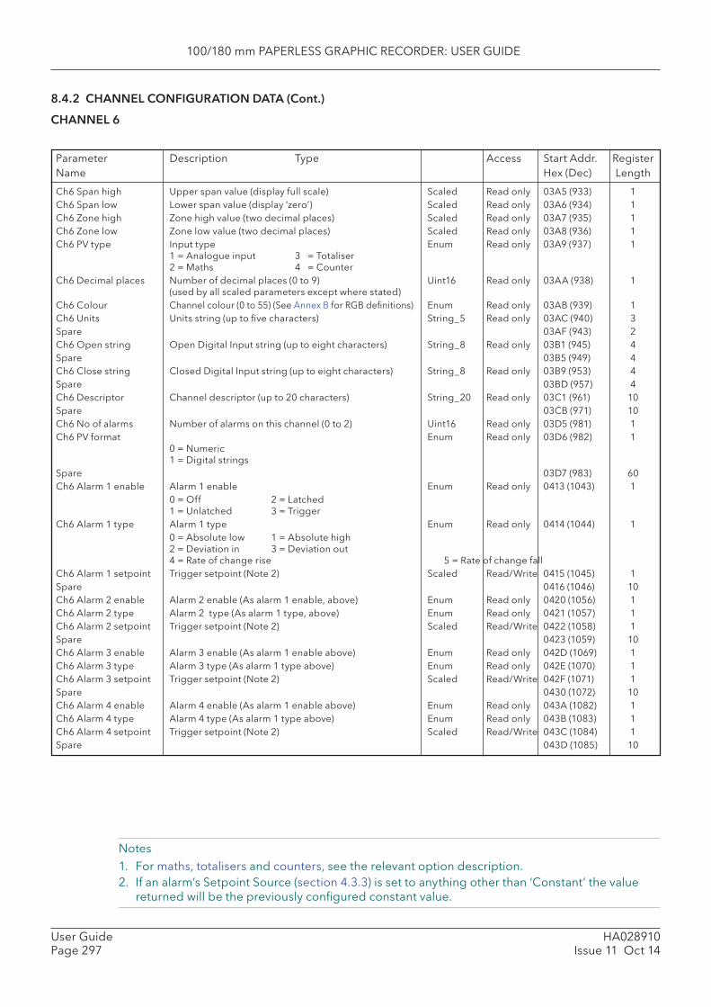
100/180 mm PAPERLESS GRAPHIC RECORDER: USER GUIDE
HA028910Issue 11 Oct 14
User GuidePage 297
8.4.2 CHANNEL CONFIGURATION DATA (Cont.)
CHANNEL 6
Notes1. For maths, totalisers and counters, see the relevant option description.2. If an alarm’s Setpoint Source (section 4.3.3) is set to anything other than ‘Constant’ the value
returned will be the previously confi gured constant value.
Parameter Description Type Access Start Addr. RegisterName Hex (Dec) Length
Ch6 Span high Upper span value (display full scale) Scaled Read only 03A5 (933) 1Ch6 Span low Lower span value (display ‘zero’) Scaled Read only 03A6 (934) 1Ch6 Zone high Zone high value (two decimal places) Scaled Read only 03A7 (935) 1Ch6 Zone low Zone low value (two decimal places) Scaled Read only 03A8 (936) 1Ch6 PV type Input type Enum Read only 03A9 (937) 1
1 = Analogue input 3 = Totaliser2 = Maths 4 = Counter
Ch6 Decimal places Number of decimal places (0 to 9) Uint16 Read only 03AA (938) 1(used by all scaled parameters except where stated)
Ch6 Colour Channel colour (0 to 55) (See Annex B for RGB defi nitions) Enum Read only 03AB (939) 1Ch6 Units Units string (up to fi ve characters) String_5 Read only 03AC (940) 3Spare 03AF (943) 2Ch6 Open string Open Digital Input string (up to eight characters) String_8 Read only 03B1 (945) 4Spare 03B5 (949) 4Ch6 Close string Closed Digital Input string (up to eight characters) String_8 Read only 03B9 (953) 4Spare 03BD (957) 4Ch6 Descriptor Channel descriptor (up to 20 characters) String_20 Read only 03C1 (961) 10Spare 03CB (971) 10Ch6 No of alarms Number of alarms on this channel (0 to 2) Uint16 Read only 03D5 (981) 1Ch6 PV format Enum Read only 03D6 (982) 1
0 = Numeric1 = Digital strings
Spare 03D7 (983) 60Ch6 Alarm 1 enable Alarm 1 enable Enum Read only 0413 (1043) 1 0 = Off 2 = Latched
1 = Unlatched 3 = Trigger Ch6 Alarm 1 type Alarm 1 type Enum Read only 0414 (1044) 1 0 = Absolute low 1 = Absolute high
2 = Deviation in 3 = Deviation out4 = Rate of change rise 5 = Rate of change fall
Ch6 Alarm 1 setpoint Trigger setpoint (Note 2) Scaled Read/Write 0415 (1045) 1Spare 0416 (1046) 10Ch6 Alarm 2 enable Alarm 2 enable (As alarm 1 enable, above) Enum Read only 0420 (1056) 1Ch6 Alarm 2 type Alarm 2 type (As alarm 1 type, above) Enum Read only 0421 (1057) 1Ch6 Alarm 2 setpoint Trigger setpoint (Note 2) Scaled Read/Write 0422 (1058) 1Spare 0423 (1059) 10Ch6 Alarm 3 enable Alarm 3 enable (As alarm 1 enable above) Enum Read only 042D (1069) 1Ch6 Alarm 3 type Alarm 3 type (As alarm 1 type above) Enum Read only 042E (1070) 1Ch6 Alarm 3 setpoint Trigger setpoint (Note 2) Scaled Read/Write 042F (1071) 1Spare 0430 (1072) 10Ch6 Alarm 4 enable Alarm 4 enable (As alarm 1 enable above) Enum Read only 043A (1082) 1Ch6 Alarm 4 type Alarm 4 type (As alarm 1 type above) Enum Read only 043B (1083) 1Ch6 Alarm 4 setpoint Trigger setpoint (Note 2) Scaled Read/Write 043C (1084) 1Spare 043D (1085) 10

100/180 mm PAPERLESS GRAPHIC RECORDER: USER GUIDE
HA028910Issue 11 Oct 14
User GuidePage 298
8.4.2 CHANNEL CONFIGURATION DATA (Cont.)
CHANNEL 7
Notes1. For maths, totalisers and counters, see the relevant option description.2. If an alarm’s Setpoint Source (section 4.3.3) is set to anything other than ‘Constant’ the value
returned will be the previously confi gured constant value.
Parameter Description Type Access Start Addr. RegisterName Hex (Dec) Length
Ch7 Span high Upper span value (display full scale) Scaled Read only 0447 (1095) 1Ch7 Span low Lower span value (display ‘zero’) Scaled Read only 0448 (1096) 1Ch7 Zone high Zone high value (two decimal places) Scaled Read only 0449 (1097) 1Ch7 Zone low Zone low value (two decimal places) Scaled Read only 044A (1098) 1Ch7 PV type Input type Enum Read only 044B (1099) 1
1 = Analogue input 3 = Totaliser2 = Maths 4 = Counter
Ch7 Decimal places Number of decimal places (0 to 9) Uint16 Read only 044C (1100) 1(used by all scaled parameters except where stated)
Ch7 Colour Channel colour (0 to 55) (See Annex B for RGB defi nitions) Enum Read only 044D (1101) 1Ch7 Units Units string (up to fi ve characters) String_5 Read only 044E (1102) 3Spare 0451 (1105) 2Ch7 Open string Open Digital Input string (up to eight characters) String_8 Read only 0453 (1107) 4Spare 0457 (1111) 4Ch7 Close string Closed Digital Input string (up to eight characters) String_8 Read only 045B (1115) 4Spare 045F (1119) 4Ch7 Descriptor Channel descriptor (up to 20 characters) String_20 Read only 0463 (1123) 10Spare 046D (1133) 10Ch7 No of alarms Number of alarms on this channel (0 to 2) Uint16 Read only 0477 (1143) 1Ch7 PV format Enum Read only 0478 (1144) 1
0 = Numeric1 = Digital strings
Spare 0479 (1145) 60Ch7 Alarm 1 enable Alarm 1 enable Enum Read only 04B5 (1205) 1 0 = Off 2 = Latched
1 = Unlatched 3 = Trigger Ch7 Alarm 1 type Alarm 1 type Enum Read only 04B6 (1206) 1 0 = Absolute low 1 = Absolute high
2 = Deviation in 3 = Deviation out4 = Rate of change rise 5 = Rate of change fall
Ch7 Alarm 1 setpoint Trigger setpoint (Note 2) Scaled Read/Write 04B7 (1207) 1Spare 04B8 (1208) 10Ch7 Alarm 2 enable Alarm 2 enable (As alarm 1 enable, above) Enum Read only 04C2 (1218) 1Ch7 Alarm 2 type Alarm 2 type (As alarm 1 type, above) Enum Read only 04C3 (1219) 1Ch7 Alarm 2 setpoint Trigger setpoint (Note 2) Scaled Read/Write 04C4 (1220) 1Spare 04C5 (1221) 10Ch7 Alarm 3 enable Alarm 3 enable (As alarm 1 enable above) Enum Read only 04CF (1231) 1Ch7 Alarm 3 type Alarm 3 type (As alarm 1 type above) Enum Read only 04D0 (1232) 1Ch7 Alarm 3 setpoint Trigger setpoint (Note 2) Scaled Read/Write 04D1 (1233) 1Spare 04D2 (1234) 10Ch7 Alarm 4 enable Alarm 4 enable (As alarm 1 enable above) Enum Read only 04DC (1244) 1Ch7 Alarm 4 type Alarm 4 type (As alarm 1 type above) Enum Read only 04DD (1245) 1Ch7 Alarm 4 setpoint Trigger setpoint (Note 2) Scaled Read/Write 04DE (1246) 1Spare 04DF (1247) 10

100/180 mm PAPERLESS GRAPHIC RECORDER: USER GUIDE
HA028910Issue 11 Oct 14
User GuidePage 299
8.4.2 CHANNEL CONFIGURATION DATA (Cont.)
CHANNEL 8
Notes1. For maths, totalisers and counters, see the relevant option description.2. If an alarm’s Setpoint Source (section 4.3.3) is set to anything other than ‘Constant’ the value
returned will be the previously confi gured constant value.
Parameter Description Type Access Start Addr. RegisterName Hex (Dec) Length
Ch8 Span high Upper span value (display full scale) Scaled Read only 04E9 (1257) 1Ch8 Span low Lower span value (display ‘zero’) Scaled Read only 04EA (1258) 1Ch8 Zone high Zone high value (two decimal places) Scaled Read only 04EB (1259) 1Ch8 Zone low Zone low value (two decimal places) Scaled Read only 04EC (1260) 1Ch8 PV type Input type Enum Read only 04ED (1261) 1
1 = Analogue input 3 = Totaliser2 = Maths 4 = Counter
Ch8 Decimal places Number of decimal places (0 to 9) Uint16 Read only 04EE (1262) 1(used by all scaled parameters except where stated)
Ch8 Colour Channel colour (0 to 55) (See Annex B for RGB defi nitions) Enum Read only 04EF (1263) 1Ch8 Units Units string (up to fi ve characters) String_5 Read only 04F0 (1264) 3Spare 04F3 (1267) 2Ch8 Open string Open Digital Input string (up to eight characters) String_8 Read only 04F5 (1269) 4Spare 04F9 (1273) 4Ch8 Close string Closed Digital Input string (up to eight characters) String_8 Read only 04FD (1277) 4Spare 0501 (1281) 4Ch8 Descriptor Channel descriptor (up to 20 characters) String_20 Read only 0505 (1285) 10Spare 050F (1295) 10Ch8 No of alarms Number of alarms on this channel (0 to 2) Uint16 Read only 0519 (1305) 1Ch8 PV format Enum Read only 051A (1306) 1
0 = Numeric1 = Digital strings
Spare 051B (1307) 60Ch8 Alarm 1 enable Alarm 1 enable Enum Read only 0557 (1367) 1 0 = Off 2 = Latched
1 = Unlatched 3 = Trigger Ch8 Alarm 1 type Alarm 1 type Enum Read only 0558 (1368) 1 0 = Absolute low 1 = Absolute high
2 = Deviation in 3 = Deviation out4 = Rate of change rise 5 = Rate of change fall
Ch8 Alarm 1 setpoint Trigger setpoint (Note 2) Scaled Read/Write 0559 (1369) 1Spare 055A (1370) 10Ch8 Alarm 2 enable Alarm 2 enable (As alarm 1 enable, above) Enum Read only 0564 (1380) 1Ch8 Alarm 2 type Alarm 2 type (As alarm 1 type, above) Enum Read only 0565 (1381) 1Ch8 Alarm 2 setpoint Trigger setpoint (Note 2) Scaled Read/Write 0566 (1382) 1Spare 0567 (1383) 10Ch8 Alarm 3 enable Alarm 3 enable (As alarm 1 enable above) Enum Read only 0571(1393) 1Ch8 Alarm 3 type Alarm 3 type (As alarm 1 type above) Enum Read only 0572 (1394) 1Ch8 Alarm 3 setpoint Trigger setpoint (Note 2) Scaled Read/Write 0573 (1395) 1Spare 0574 (1396) 10Ch8 Alarm 4 enable Alarm 4 enable (As alarm 1 enable above) Enum Read only 057E (1406) 1Ch8 Alarm 4 type Alarm 4 type (As alarm 1 type above) Enum Read only 057F (1407) 1Ch8 Alarm 4 setpoint Trigger setpoint (Note 2) Scaled Read/Write 0580 (1408) 1Spare 0581 (1409) 10

100/180 mm PAPERLESS GRAPHIC RECORDER: USER GUIDE
HA028910Issue 11 Oct 14
User GuidePage 300
8.4.2 CHANNEL CONFIGURATION DATA (Cont.)
CHANNEL 9
Notes1. For maths, totalisers and counters, see the relevant option description.2. If an alarm’s Setpoint Source (section 4.3.3) is set to anything other than ‘Constant’ the value
returned will be the previously confi gured constant value.
Parameter Description Type Access Start Addr. RegisterName Hex (Dec) Length
Ch9 Span high Upper span value (display full scale) Scaled Read only 058B (1419) 1Ch9 Span low Lower span value (display ‘zero’) Scaled Read only 058C (1420) 1Ch9 Zone high Zone high value (two decimal places) Scaled Read only 058D (1421) 1Ch9 Zone low Zone low value (two decimal places) Scaled Read only 058E (1422) 1Ch9 PV type Input type Enum Read only 058F (1423) 1
1 = Analogue input 3 = Totaliser2 = Maths 4 = Counter
Ch9 Decimal places Number of decimal places (0 to 9) Uint16 Read only 0590 (1424) 1(used by all scaled parameters except where stated)
Ch9 Colour Channel colour (0 to 55) (See Annex B for RGB defi nitions) Enum Read only 0591 (1425) 1Ch9 Units Units string (up to fi ve characters) String_5 Read only 0592 (1426) 3Spare 0595 (1429) 2Ch9 Open string Open Digital Input string (up to eight characters) String_8 Read only 0597 (1431) 4Spare 059B (1435) 4Ch9 Close string Closed Digital Input string (up to eight characters) String_8 Read only 059F (1439) 4Spare 05A3 (1443) 4Ch9 Descriptor Channel descriptor (up to 20 characters) String_20 Read only 05A7 (1447) 10Spare 05B1 (1457) 10Ch9 No of alarms Number of alarms on this channel (0 to 2) Uint16 Read only 05BB (1467) 1Ch9 PV format Enum Read only 05BC (1468) 1
0 = Numeric1 = Digital strings
Spare 05BD (1469) 60Ch9 Alarm 1 enable Alarm 1 enable Enum Read only 05F9 (1529) 1 0 = Off 2 = Latched
1 = Unlatched 3 = Trigger Ch9 Alarm 1 type Alarm 1 type Enum Read only 05FA (1530) 1 0 = Absolute low 1 = Absolute high
2 = Deviation in 3 = Deviation out4 = Rate of change rise 5 = Rate of change fall
Ch9 Alarm 1 setpoint Trigger setpoint (Note 2) Scaled Read/Write 05FB (1531) 1Spare 05FC (1532) 10Ch9 Alarm 2 enable Alarm 2 enable (As alarm 1 enable, above) Enum Read only 0606 (1542) 1Ch9 Alarm 2 type Alarm 2 type (As alarm 1 type, above) Enum Read only 0607 (1543) 1Ch9 Alarm 2 setpoint Trigger setpoint (Note 2) Scaled Read/Write 0608 (1544) 1Spare 0609 (1545) 10Ch9 Alarm 3 enable Alarm 3 enable (As alarm 1 enable above) Enum Read only 0613(1555) 1Ch9 Alarm 3 type Alarm 3 type (As alarm 1 type above) Enum Read only 0614 (1556) 1Ch9 Alarm 3 setpoint Trigger setpoint (Note 2) Scaled Read/Write 0615 (1557) 1Spare 0616 (1558) 10Ch9 Alarm 4 enable Alarm 4 enable (As alarm 1 enable above) Enum Read only 0620 (1568) 1Ch9 Alarm 4 type Alarm 4 type (As alarm 1 type above) Enum Read only 0621 (1569) 1Ch9 Alarm 4 setpoint Trigger setpoint (Note 2) Scaled Read/Write 0622 (1570) 1Spare 0623 (1571) 10

100/180 mm PAPERLESS GRAPHIC RECORDER: USER GUIDE
HA028910Issue 11 Oct 14
User GuidePage 301
8.4.2 CHANNEL CONFIGURATION DATA (Cont.)
CHANNEL 10
Notes1. For maths, totalisers and counters, see the relevant option description.2. If an alarm’s Setpoint Source (section 4.3.3) is set to anything other than ‘Constant’ the value
returned will be the previously confi gured constant value.
Parameter Description Type Access Start Addr. RegisterName Hex (Dec) Length
Ch10 Span high Upper span value (display full scale) Scaled Read only 062D (1581) 1Ch10 Span low Lower span value (display ‘zero’) Scaled Read only 062E (1582) 1Ch10 Zone high Zone high value (two decimal places) Scaled Read only 062F (1583) 1Ch10 Zone low Zone low value (two decimal places) Scaled Read only 0630 (1584) 1Ch10 PV type Input type Enum Read only 0631 (1585) 1
1 = Analogue input 3 = Totaliser2 = Maths 4 = Counter
Ch10 Decimal places Number of decimal places (0 to 9) Uint16 Read only 0632 (1586) 1(used by all scaled parameters except where stated)
Ch10 Colour Channel colour (0 to 55) (See Annex B for RGB defi nitions) Enum Read only 0633 (1587) 1Ch10 Units Units string (up to fi ve characters) String_5 Read only 0634 (1588) 3Spare 0637 (1591) 2Ch10 Open string Open Digital Input string (up to eight characters) String_8 Read only 0639 (1593) 4Spare 063D (1597) 4Ch10 Close string Closed Digital Input string (up to eight characters) String_8 Read only 0641 (1601) 4Spare 0645 (1605) 4Ch10 Descriptor Channel descriptor (up to 20 characters) String_20 Read only 0649 (1609) 10Spare 0653 (1619) 10Ch10 No of alarms Number of alarms on this channel (0 to 2) Uint16 Read only 065D (1629) 1Ch10 PV format Enum Read only 065E (1630) 1
0 = Numeric1 = Digital strings
Spare 065F (1631) 60Ch10 Alarm 1 enable Alarm 1 enable Enum Read only 069B (1691) 1 0 = Off 2 = Latched
1 = Unlatched 3 = Trigger Ch10 Alarm 1 type Alarm 1 type Enum Read only 069C (1692) 1 0 = Absolute low 1 = Absolute high
2 = Deviation in 3 = Deviation out4 = Rate of change rise 5 = Rate of change fall
Ch10 Alarm 1 setpoint Trigger setpoint (Note 2) Scaled Read/Write 069D (1693) 1Spare 069E (1694) 10Ch10 Alarm 2 enable Alarm 2 enable (As alarm 1 enable, above) Enum Read only 06A8 (1704) 1Ch10 Alarm 2 type Alarm 2 type (As alarm 1 type, above) Enum Read only 06A9 (1705) 1Ch10 Alarm 2 setpoint Trigger setpoint (Note 2) Scaled Read/Write 06AA (1706) 1Spare 06AB (1707) 10Ch10 Alarm 3 enable Alarm 3 enable (As alarm 1 enable above) Enum Read only 06B5(1717) 1Ch10 Alarm 3 type Alarm 3 type (As alarm 1 type above) Enum Read only 06B6(1718) 1Ch10 Alarm 3 setpoint Trigger setpoint (Note 2) Scaled Read/Write 06B7 (1719) 1Spare 06B8 (1720) 10Ch10 Alarm 4 enable Alarm 4 enable (As alarm 1 enable above) Enum Read only 06C2 (1730) 1Ch10 Alarm 4 type Alarm 4 type (As alarm 1 type above) Enum Read only 06C3 (1731) 1Ch10 Alarm 4 setpoint Trigger setpoint (Note 2) Scaled Read/Write 06C4 (1732) 1Spare 06C5 (1733) 10

100/180 mm PAPERLESS GRAPHIC RECORDER: USER GUIDE
HA028910Issue 11 Oct 14
User GuidePage 302
8.4.2 CHANNEL CONFIGURATION DATA (Cont.)
CHANNEL 11
Notes1. For maths, totalisers and counters, see the relevant option description.2. If an alarm’s Setpoint Source (section 4.3.3) is set to anything other than ‘Constant’ the value
returned will be the previously confi gured constant value.
Parameter Description Type Access Start Addr. RegisterName Hex (Dec) Length
Ch11 Span high Upper span value (display full scale) Scaled Read only 06CF (1743) 1Ch11 Span low Lower span value (display ‘zero’) Scaled Read only 06D0 (1744) 1Ch11 Zone high Zone high value (two decimal places) Scaled Read only 06D1 (1745) 1Ch11 Zone low Zone low value (two decimal places) Scaled Read only 06D2 (1746) 1Ch11 PV type Input type Enum Read only 06D3 (1747) 1
1 = Analogue input 3 = Totaliser2 = Maths 4 = Counter
Ch11 Decimal places Number of decimal places (0 to 9) Uint16 Read only 06D4 (1748) 1(used by all scaled parameters except where stated)
Ch11 Colour Channel colour (0 to 55) (See Annex B for RGB defi nitions) Enum Read only 06D5 (1749) 1Ch11 Units Units string (up to fi ve characters) String_5 Read only 06D6 (1750) 3Spare 06D9 (1753) 2Ch11 Open string Open Digital Input string (up to eight characters) String_8 Read only 06DB (1755) 4Spare 06DF (1759) 4Ch11 Close string Closed Digital Input string (up to eight characters) String_8 Read only 06E3 (1763) 4Spare 06E7 (1767) 4Ch11 Descriptor Channel descriptor (up to 20 characters) String_20 Read only 06EB (1771) 10Spare 06F5 (1781) 10Ch11 No of alarms Number of alarms on this channel (0 to 2) Uint16 Read only 06FF (1791) 1Ch11 PV format Enum Read only 0700 (1792) 1
0 = Numeric1 = Digital strings
Spare 0701 (1793) 60Ch11 Alarm 1 enable Alarm 1 enable Enum Read only 073D (1853) 1 0 = Off 2 = Latched
1 = Unlatched 3 = Trigger Ch11 Alarm 1 type Alarm 1 type Enum Read only 073E (1854) 1 0 = Absolute low 1 = Absolute high
2 = Deviation in 3 = Deviation out4 = Rate of change rise 5 = Rate of change fall
Ch11 Alarm 1 setpoint Trigger setpoint (Note 2) Scaled Read/Write 073F (1855) 1Spare 0740 (1856) 10Ch11 Alarm 2 enable Alarm 2 enable (As alarm 1 enable, above) Enum Read only 074A (1866) 1Ch11 Alarm 2 type Alarm 2 type (As alarm 1 type, above) Enum Read only 074B (1867) 1Ch11 Alarm 2 setpoint Trigger setpoint (Note 2) Scaled Read/Write 074C (1868) 1Spare 074D (1869) 10Ch11 Alarm 3 enable Alarm 3 enable (As alarm 1 enable above) Enum Read only 0757(1879) 1Ch11 Alarm 3 type Alarm 3 type (As alarm 1 type above) Enum Read only 0758 (1880) 1Ch11 Alarm 3 setpoint Trigger setpoint (Note 2) Scaled Read/Write 0759 (1881) 1Spare 075A (1882) 10Ch11 Alarm 4 enable Alarm 4 enable (As alarm 1 enable above) Enum Read only 0764 (1892) 1Ch11 Alarm 4 type Alarm 4 type (As alarm 1 type above) Enum Read only 0765 (1893) 1Ch11 Alarm 4 setpoint Trigger setpoint (Note 2) Scaled Read/Write 0766 (1894) 1Spare 0767 (1895) 10

100/180 mm PAPERLESS GRAPHIC RECORDER: USER GUIDE
HA028910Issue 11 Oct 14
User GuidePage 303
8.4.2 CHANNEL CONFIGURATION DATA (Cont.)
CHANNEL 12
Notes1. For maths, totalisers and counters, see the relevant option description.2. If an alarm’s Setpoint Source (section 4.3.3) is set to anything other than ‘Constant’ the value
returned will be the previously confi gured constant value.
Parameter Description Type Access Start Addr. RegisterName Hex (Dec) Length
Ch12 Span high Upper span value (display full scale) Scaled Read only 0771 (1905) 1Ch12 Span low Lower span value (display ‘zero’) Scaled Read only 0772 (1906) 1Ch12 Zone high Zone high value (two decimal places) Scaled Read only 0773 (1907) 1Ch12 Zone low Zone low value (two decimal places) Scaled Read only 0774 (1908) 1Ch12 PV type Input type Enum Read only 0775 (1909) 1
1 = Analogue input 3 = Totaliser2 = Maths 4 = Counter
Ch12 Decimal places Number of decimal places (0 to 9) Uint16 Read only 0776 (1910) 1(used by all scaled parameters except where stated)
Ch12 Colour Channel colour (0 to 55) (See Annex B for RGB defi nitions) Enum Read only 0777 (1911) 1Ch12 Units Units string (up to fi ve characters) String_5 Read only 0778 (1912) 3Spare 077B (1915) 2Ch12 Open string Open Digital Input string (up to eight characters) String_8 Read only 077D (1917) 4Spare 0781 (1921) 4Ch12 Close string Closed Digital Input string (up to eight characters) String_8 Read only 0785 (1925) 4Spare 0789 (1929) 4Ch12 Descriptor Channel descriptor (up to 20 characters) String_20 Read only 078D (1933) 10Spare 0797 (1943) 10Ch12 No of alarms Number of alarms on this channel (0 to 2) Uint16 Read only 07A1 (1953) 1Ch12 PV format Enum Read only 07A2 (1954) 1
0 = Numeric1 = Digital strings
Spare 07A3 (1955) 60Ch12 Alarm 1 enable Alarm 1 enable Enum Read only 07DF (2015) 1 0 = Off 2 = Latched
1 = Unlatched 3 = Trigger Ch12 Alarm 1 type Alarm 1 type Enum Read only 07E0 (2016) 1 0 = Absolute low 1 = Absolute high
2 = Deviation in 3 = Deviation out4 = Rate of change rise 5 = Rate of change fall
Ch12 Alarm 1 setpoint Trigger setpoint (Note 2) Scaled Read/Write 07E1 (2017) 1Spare 07E2 (2018) 10Ch12 Alarm 2 enable Alarm 2 enable (As alarm 1 enable, above) Enum Read only 07EC (2028) 1Ch12 Alarm 2 type Alarm 2 type (As alarm 1 type, above) Enum Read only 07ED (2029) 1Ch12 Alarm 2 setpoint Trigger setpoint (Note 2) Scaled Read/Write 07EE (2030) 1Spare 07EF (2031) 10Ch12 Alarm 3 enable Alarm 3 enable (As alarm 1 enable above) Enum Read only 07F9 (2041) 1Ch12 Alarm 3 type Alarm 3 type (As alarm 1 type above) Enum Read only 07FA (2042) 1Ch12 Alarm 3 setpoint Trigger setpoint (Note 2) Scaled Read/Write 07FB (2043) 1Spare 07FC (2044) 10Ch12 Alarm 4 enable Alarm 4 enable (As alarm 1 enable above) Enum Read only 0806 (2054) 1Ch12 Alarm 4 type Alarm 4 type (As alarm 1 type above) Enum Read only 0807 (2055) 1Ch12 Alarm 4 setpoint Trigger setpoint (Note 2) Scaled Read/Write 0808 (2056) 1Spare 0809 (2057) 10
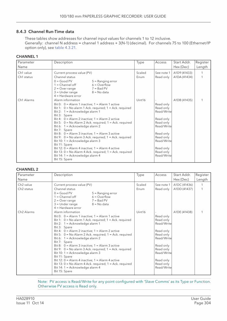
100/180 mm PAPERLESS GRAPHIC RECORDER: USER GUIDE
HA028910Issue 11 Oct 14
User GuidePage 304
Note: PV access is Read/Write for any point confi gured with ‘Slave Comms’ as its Type or Function. Otherwise PV access is Read only.
8.4.3 Channel Run-Time data
These tables show addresses for channel input values for channels 1 to 12 inclusive. Generally: channel N address = channel 1 address + 3(N-1) (decimal). For channels 75 to 100 (Ethernet/IP option only), see table 4.3.21.
CHANNEL 1Parameter Description Type Access Start Addr. RegisterName Hex (Dec) Length
Ch1 value Current process value (PV) Scaled See note 1 A1D9 (41433) 1Ch1 status Channel status Enum Read only A1DA (41434) 1 0 = Good PV 5 = Ranging error
1 = Channel off 6 = Overfl ow2 = Over range 7 = Bad PV3 = Under range 8 = No data4 = Hardware error
Ch1 Alarms Alarm information Uint16 - A1DB (41435) 1 Bit 0: 0 = Alarm 1 inactive; 1 = Alarm 1 active Read only
Bit 1: 0 = No alarm 1 Ack. required; 1 = Ack. required Read onlyBit 2: 1 = Acknowledge alarm 1 Read/WriteBit 3: SpareBit 4: 0 = Alarm 2 inactive; 1 = Alarm 2 active Read onlyBit 5: 0 = No Alarm 2 Ack. required; 1 = Ack. required Read onlyBit 6: 1 = Acknowledge alarm 2 Read/WriteBit 7: SpareBit 8: 0 = Alarm 3 inactive; 1 = Alarm 3 active Read onlyBit 9: 0 = No alarm 3 Ack. required; 1 = Ack. required Read onlyBit 10: 1 = Acknowledge alarm 3 Read/WriteBit 11: SpareBit 12: 0 = Alarm 4 inactive; 1 = Alarm 4 active Read onlyBit 13: 0 = No Alarm 4 Ack. required; 1 = Ack. required Read onlyBit 14: 1 = Acknowledge alarm 4 Read/WriteBit 15: Spare
CHANNEL 2Parameter Description Type Access Start Addr. RegisterName Hex (Dec) Length
Ch2 value Current process value (PV) Scaled See note 1 A1DC (41436) 1Ch2 status Channel status Enum Read only A1DD (41437) 1 0 = Good PV 5 = Ranging error
1 = Channel off 6 = Overfl ow2 = Over range 7 = Bad PV3 = Under range 8 = No data4 = Hardware error
Ch2 Alarms Alarm information Uint16 - A1DE (41438) 1 Bit 0: 0 = Alarm 1 inactive; 1 = Alarm 1 active Read only
Bit 1: 0 = No alarm 1 Ack. required; 1 = Ack. required Read onlyBit 2: 1 = Acknowledge alarm 1 Read/WriteBit 3: SpareBit 4: 0 = Alarm 2 inactive; 1 = Alarm 2 active Read onlyBit 5: 0 = No Alarm 2 Ack. required; 1 = Ack. required Read onlyBit 6: 1 = Acknowledge alarm 2 Read/WriteBit 7: SpareBit 8: 0 = Alarm 3 inactive; 1 = Alarm 3 active Read onlyBit 9: 0 = No alarm 3 Ack. required; 1 = Ack. required Read onlyBit 10: 1 = Acknowledge alarm 3 Read/WriteBit 11: SpareBit 12: 0 = Alarm 4 inactive; 1 = Alarm 4 active Read onlyBit 13: 0 = No Alarm 4 Ack. required; 1 = Ack. required Read onlyBit 14: 1 = Acknowledge alarm 4 Read/WriteBit 15: Spare

100/180 mm PAPERLESS GRAPHIC RECORDER: USER GUIDE
HA028910Issue 11 Oct 14
User GuidePage 305
Note: PV access is Read/Write for any point confi gured with ‘Slave Comms’ as its Type or Function. Otherwise PV access is Read only.
8.4.3 CHANNEL RUN TIME DATA (Cont.)
CHANNEL 3
Parameter Description Type Access Start Addr. RegisterName Hex (Dec) Length
Ch3 value Current process value (PV) Scaled See note 1 A1DF (41439) 1Ch3 status Channel status Enum Read only A1E0 (41440) 1 0 = Good PV 5 = Ranging error
1 = Channel off 6 = Overfl ow2 = Over range 7 = Bad PV3 = Under range 8 = No data4 = Hardware error
Ch3 Alarms Alarm information Uint16 - A1E1 (41441) 1 Bit 0: 0 = Alarm 1 inactive; 1 = Alarm 1 active Read only
Bit 1: 0 = No alarm 1 Ack. required; 1 = Ack. required Read onlyBit 2: 1 = Acknowledge alarm 1 Read/WriteBit 3: SpareBit 4: 0 = Alarm 2 inactive; 1 = Alarm 2 active Read onlyBit 5: 0 = No Alarm 2 Ack. required; 1 = Ack. required Read onlyBit 6: 1 = Acknowledge alarm 2 Read/WriteBit 7: SpareBit 8: 0 = Alarm 3 inactive; 1 = Alarm 3 active Read onlyBit 9: 0 = No alarm 3 Ack. required; 1 = Ack. required Read onlyBit 10: 1 = Acknowledge alarm 3 Read/WriteBit 11: SpareBit 12: 0 = Alarm 4 inactive; 1 = Alarm 4 active Read onlyBit 13: 0 = No Alarm 4 Ack. required; 1 = Ack. required Read onlyBit 14: 1 = Acknowledge alarm 4 Read/WriteBit 15: Spare
CHANNEL 4
Parameter Description Type Access Start Addr. RegisterName Hex (Dec) Length
Ch4 value Current process value (PV) Scaled See note 1 A1E2 (41442) 1Ch4 status Channel status Enum Read only A1E3 (41443) 1 0 = Good PV 5 = Ranging error
1 = Channel off 6 = Overfl ow2 = Over range 7 = Bad PV3 = Under range 8 = No data4 = Hardware error
Ch4 Alarms Alarm information Uint16 - A1E4 (41444) 1 Bit 0: 0 = Alarm 1 inactive; 1 = Alarm 1 active Read only
Bit 1: 0 = No alarm 1 Ack. required; 1 = Ack. required Read onlyBit 2: 1 = Acknowledge alarm 1 Read/WriteBit 3: SpareBit 4: 0 = Alarm 2 inactive; 1 = Alarm 2 active Read onlyBit 5: 0 = No Alarm 2 Ack. required; 1 = Ack. required Read onlyBit 6: 1 = Acknowledge alarm 2 Read/WriteBit 7: SpareBit 8: 0 = Alarm 3 inactive; 1 = Alarm 3 active Read onlyBit 9: 0 = No alarm 3 Ack. required; 1 = Ack. required Read onlyBit 10: 1 = Acknowledge alarm 3 Read/WriteBit 11: SpareBit 12: 0 = Alarm 4 inactive; 1 = Alarm 4 active Read onlyBit 13: 0 = No Alarm 4 Ack. required; 1 = Ack. required Read onlyBit 14: 1 = Acknowledge alarm 4 Read/WriteBit 15: Spare

100/180 mm PAPERLESS GRAPHIC RECORDER: USER GUIDE
HA028910Issue 11 Oct 14
User GuidePage 306
Note: PV access is Read/Write for any point confi gured with ‘Slave Comms’ as its Type or Function. Otherwise PV access is Read only.
8.4.3 CHANNEL RUN TIME DATA (Cont.)
CHANNEL 5
Parameter Description Type Access Start Addr. RegisterName Hex (Dec) Length
Parameter Description Type Access Start Addr. RegisterName Hex (Dec) Length
Ch5 value Current process value (PV) Scaled See note 1 A1E5 (41445) 1Ch5 status Channel status Enum Read only A1E6 (41446) 1 0 = Good PV 5 = Ranging error
1 = Channel off 6 = Overfl ow2 = Over range 7 = Bad PV3 = Under range 8 = No data4 = Hardware error
Ch5 Alarms Alarm information Uint16 - A1E7 (41447) 1 Bit 0: 0 = Alarm 1 inactive; 1 = Alarm 1 active Read only
Bit 1: 0 = No alarm 1 Ack. required; 1 = Ack. required Read onlyBit 2: 1 = Acknowledge alarm 1 Read/WriteBit 3: SpareBit 4: 0 = Alarm 2 inactive; 1 = Alarm 2 active Read onlyBit 5: 0 = No Alarm 2 Ack. required; 1 = Ack. required Read onlyBit 6: 1 = Acknowledge alarm 2 Read/WriteBit 7: SpareBit 8: 0 = Alarm 3 inactive; 1 = Alarm 3 active Read onlyBit 9: 0 = No alarm 3 Ack. required; 1 = Ack. required Read onlyBit 10: 1 = Acknowledge alarm 3 Read/WriteBit 11: SpareBit 12: 0 = Alarm 4 inactive; 1 = Alarm 4 active Read onlyBit 13: 0 = No Alarm 4 Ack. required; 1 = Ack. required Read onlyBit 14: 1 = Acknowledge alarm 4 Read/WriteBit 15: Spare
CHANNEL 6
Ch6 value Current process value (PV) Scaled See note 1 A1E8 (41448) 1Ch6 status Channel status Enum Read only A1E9 (41449) 1 0 = Good PV 5 = Ranging error
1 = Channel off 6 = Overfl ow2 = Over range 7 = Bad PV3 = Under range 8 = No data4 = Hardware error
Ch6 Alarms Alarm information Uint16 - A1EA (41450) 1 Bit 0: 0 = Alarm 1 inactive; 1 = Alarm 1 active Read only
Bit 1: 0 = No alarm 1 Ack. required; 1 = Ack. required Read onlyBit 2: 1 = Acknowledge alarm 1 Read/WriteBit 3: SpareBit 4: 0 = Alarm 2 inactive; 1 = Alarm 2 active Read onlyBit 5: 0 = No Alarm 2 Ack. required; 1 = Ack. required Read onlyBit 6: 1 = Acknowledge alarm 2 Read/WriteBit 7: SpareBit 8: 0 = Alarm 3 inactive; 1 = Alarm 3 active Read onlyBit 9: 0 = No alarm 3 Ack. required; 1 = Ack. required Read onlyBit 10: 1 = Acknowledge alarm 3 Read/WriteBit 11: SpareBit 12: 0 = Alarm 4 inactive; 1 = Alarm 4 active Read onlyBit 13: 0 = No Alarm 4 Ack. required; 1 = Ack. required Read onlyBit 14: 1 = Acknowledge alarm 4 Read/WriteBit 15: Spare

100/180 mm PAPERLESS GRAPHIC RECORDER: USER GUIDE
HA028910Issue 11 Oct 14
User GuidePage 307
Note: PV access is Read/Write for any point confi gured with ‘Slave Comms’ as its Type or Function. Otherwise PV access is Read only.
8.4.3 CHANNEL RUN TIME DATA (Cont.)
CHANNEL 7
Parameter Description Type Access Start Addr. RegisterName Hex (Dec) Length
Parameter Description Type Access Start Addr. RegisterName Hex (Dec) Length
Ch7 value Current process value (PV) Scaled See note 1 A1EB (41451) 1Ch7 status Channel status Enum Read only A1EC (41452) 1 0 = Good PV 5 = Ranging error
1 = Channel off 6 = Overfl ow2 = Over range 7 = Bad PV3 = Under range 8 = No data4 = Hardware error
Ch7 Alarms Alarm information Uint16 - A1ED (41453) 1 Bit 0: 0 = Alarm 1 inactive; 1 = Alarm 1 active Read only
Bit 1: 0 = No alarm 1 Ack. required; 1 = Ack. required Read onlyBit 2: 1 = Acknowledge alarm 1 Read/WriteBit 3: SpareBit 4: 0 = Alarm 2 inactive; 1 = Alarm 2 active Read onlyBit 5: 0 = No Alarm 2 Ack. required; 1 = Ack. required Read onlyBit 6: 1 = Acknowledge alarm 2 Read/WriteBit 7: SpareBit 8: 0 = Alarm 3 inactive; 1 = Alarm 3 active Read onlyBit 9: 0 = No alarm 3 Ack. required; 1 = Ack. required Read onlyBit 10: 1 = Acknowledge alarm 3 Read/WriteBit 11: SpareBit 12: 0 = Alarm 4 inactive; 1 = Alarm 4 active Read onlyBit 13: 0 = No Alarm 4 Ack. required; 1 = Ack. required Read onlyBit 14: 1 = Acknowledge alarm 4 Read/WriteBit 15: Spare
CHANNEL 8
Ch8 value Current process value (PV) Scaled See note 1 A1EE (41454) 1Ch8 status Channel status Enum Read only A1EF (41455) 1 0 = Good PV 5 = Ranging error
1 = Channel off 6 = Overfl ow2 = Over range 7 = Bad PV3 = Under range 8 = No data4 = Hardware error
Ch8 Alarms Alarm information Uint16 - A1F0 (41456) 1 Bit 0: 0 = Alarm 1 inactive; 1 = Alarm 1 active Read only
Bit 1: 0 = No alarm 1 Ack. required; 1 = Ack. required Read onlyBit 2: 1 = Acknowledge alarm 1 Read/WriteBit 3: SpareBit 4: 0 = Alarm 2 inactive; 1 = Alarm 2 active Read onlyBit 5: 0 = No Alarm 2 Ack. required; 1 = Ack. required Read onlyBit 6: 1 = Acknowledge alarm 2 Read/WriteBit 7: SpareBit 8: 0 = Alarm 3 inactive; 1 = Alarm 3 active Read onlyBit 9: 0 = No alarm 3 Ack. required; 1 = Ack. required Read onlyBit 10: 1 = Acknowledge alarm 3 Read/WriteBit 11: SpareBit 12: 0 = Alarm 4 inactive; 1 = Alarm 4 active Read onlyBit 13: 0 = No Alarm 4 Ack. required; 1 = Ack. required Read onlyBit 14: 1 = Acknowledge alarm 4 Read/WriteBit 15: Spare
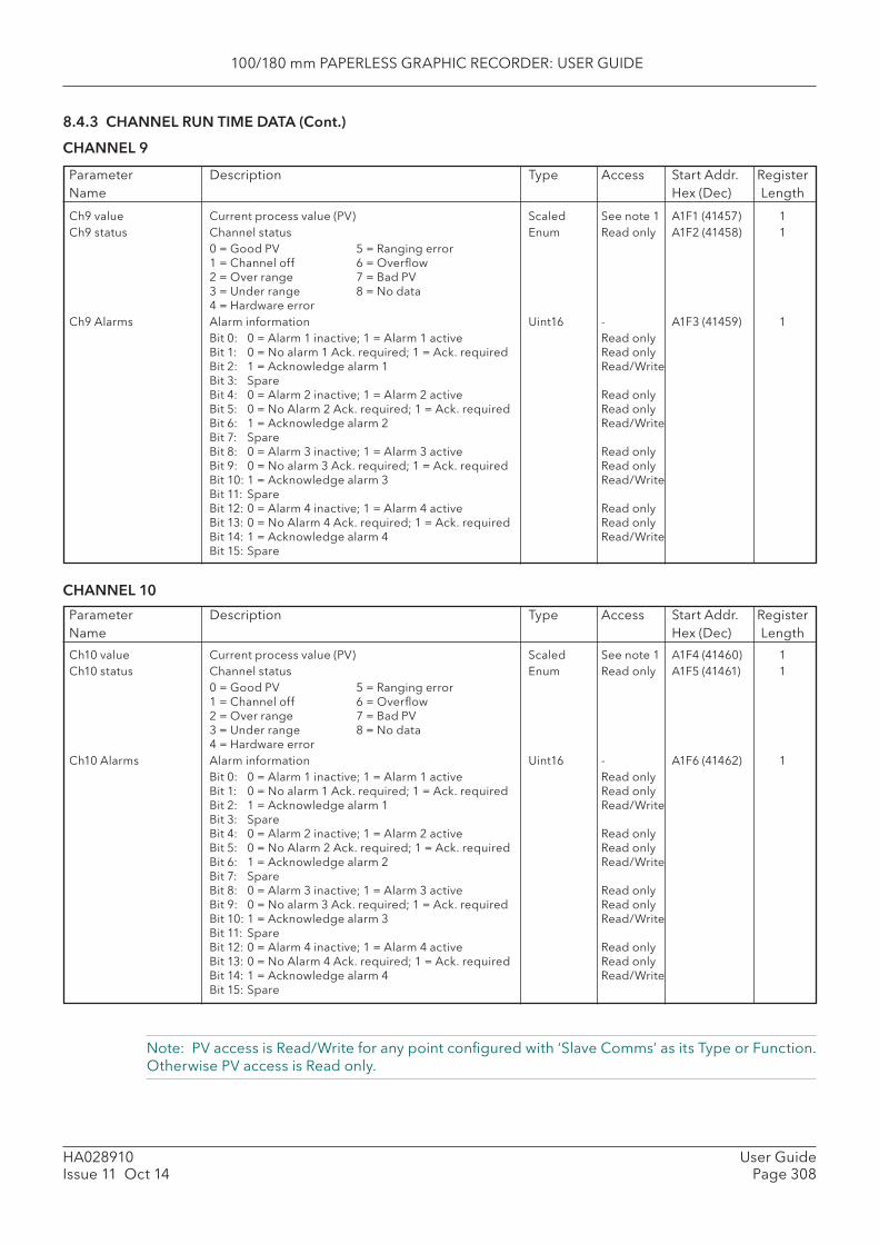
100/180 mm PAPERLESS GRAPHIC RECORDER: USER GUIDE
HA028910Issue 11 Oct 14
User GuidePage 308
Note: PV access is Read/Write for any point confi gured with ‘Slave Comms’ as its Type or Function. Otherwise PV access is Read only.
8.4.3 CHANNEL RUN TIME DATA (Cont.)
CHANNEL 9
Parameter Description Type Access Start Addr. RegisterName Hex (Dec) Length
Parameter Description Type Access Start Addr. RegisterName Hex (Dec) Length
Ch9 value Current process value (PV) Scaled See note 1 A1F1 (41457) 1Ch9 status Channel status Enum Read only A1F2 (41458) 1 0 = Good PV 5 = Ranging error
1 = Channel off 6 = Overfl ow2 = Over range 7 = Bad PV3 = Under range 8 = No data4 = Hardware error
Ch9 Alarms Alarm information Uint16 - A1F3 (41459) 1 Bit 0: 0 = Alarm 1 inactive; 1 = Alarm 1 active Read only
Bit 1: 0 = No alarm 1 Ack. required; 1 = Ack. required Read onlyBit 2: 1 = Acknowledge alarm 1 Read/WriteBit 3: SpareBit 4: 0 = Alarm 2 inactive; 1 = Alarm 2 active Read onlyBit 5: 0 = No Alarm 2 Ack. required; 1 = Ack. required Read onlyBit 6: 1 = Acknowledge alarm 2 Read/WriteBit 7: SpareBit 8: 0 = Alarm 3 inactive; 1 = Alarm 3 active Read onlyBit 9: 0 = No alarm 3 Ack. required; 1 = Ack. required Read onlyBit 10: 1 = Acknowledge alarm 3 Read/WriteBit 11: SpareBit 12: 0 = Alarm 4 inactive; 1 = Alarm 4 active Read onlyBit 13: 0 = No Alarm 4 Ack. required; 1 = Ack. required Read onlyBit 14: 1 = Acknowledge alarm 4 Read/WriteBit 15: Spare
CHANNEL 10
Ch10 value Current process value (PV) Scaled See note 1 A1F4 (41460) 1Ch10 status Channel status Enum Read only A1F5 (41461) 1 0 = Good PV 5 = Ranging error
1 = Channel off 6 = Overfl ow2 = Over range 7 = Bad PV3 = Under range 8 = No data4 = Hardware error
Ch10 Alarms Alarm information Uint16 - A1F6 (41462) 1 Bit 0: 0 = Alarm 1 inactive; 1 = Alarm 1 active Read only
Bit 1: 0 = No alarm 1 Ack. required; 1 = Ack. required Read onlyBit 2: 1 = Acknowledge alarm 1 Read/WriteBit 3: SpareBit 4: 0 = Alarm 2 inactive; 1 = Alarm 2 active Read onlyBit 5: 0 = No Alarm 2 Ack. required; 1 = Ack. required Read onlyBit 6: 1 = Acknowledge alarm 2 Read/WriteBit 7: SpareBit 8: 0 = Alarm 3 inactive; 1 = Alarm 3 active Read onlyBit 9: 0 = No alarm 3 Ack. required; 1 = Ack. required Read onlyBit 10: 1 = Acknowledge alarm 3 Read/WriteBit 11: SpareBit 12: 0 = Alarm 4 inactive; 1 = Alarm 4 active Read onlyBit 13: 0 = No Alarm 4 Ack. required; 1 = Ack. required Read onlyBit 14: 1 = Acknowledge alarm 4 Read/WriteBit 15: Spare
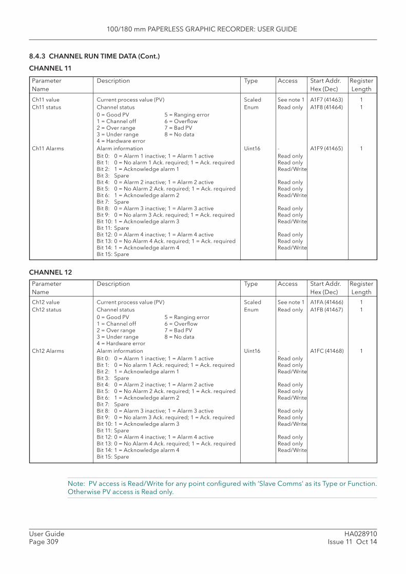
100/180 mm PAPERLESS GRAPHIC RECORDER: USER GUIDE
HA028910Issue 11 Oct 14
User GuidePage 309
Note: PV access is Read/Write for any point confi gured with ‘Slave Comms’ as its Type or Function. Otherwise PV access is Read only.
8.4.3 CHANNEL RUN TIME DATA (Cont.)
CHANNEL 11
Parameter Description Type Access Start Addr. RegisterName Hex (Dec) Length
Parameter Description Type Access Start Addr. RegisterName Hex (Dec) Length
Ch11 value Current process value (PV) Scaled See note 1 A1F7 (41463) 1Ch11 status Channel status Enum Read only A1F8 (41464) 1 0 = Good PV 5 = Ranging error
1 = Channel off 6 = Overfl ow2 = Over range 7 = Bad PV3 = Under range 8 = No data4 = Hardware error
Ch11 Alarms Alarm information Uint16 - A1F9 (41465) 1 Bit 0: 0 = Alarm 1 inactive; 1 = Alarm 1 active Read only
Bit 1: 0 = No alarm 1 Ack. required; 1 = Ack. required Read onlyBit 2: 1 = Acknowledge alarm 1 Read/WriteBit 3: SpareBit 4: 0 = Alarm 2 inactive; 1 = Alarm 2 active Read onlyBit 5: 0 = No Alarm 2 Ack. required; 1 = Ack. required Read onlyBit 6: 1 = Acknowledge alarm 2 Read/WriteBit 7: SpareBit 8: 0 = Alarm 3 inactive; 1 = Alarm 3 active Read onlyBit 9: 0 = No alarm 3 Ack. required; 1 = Ack. required Read onlyBit 10: 1 = Acknowledge alarm 3 Read/WriteBit 11: SpareBit 12: 0 = Alarm 4 inactive; 1 = Alarm 4 active Read onlyBit 13: 0 = No Alarm 4 Ack. required; 1 = Ack. required Read onlyBit 14: 1 = Acknowledge alarm 4 Read/WriteBit 15: Spare
CHANNEL 12
Ch12 value Current process value (PV) Scaled See note 1 A1FA (41466) 1Ch12 status Channel status Enum Read only A1FB (41467) 1 0 = Good PV 5 = Ranging error
1 = Channel off 6 = Overfl ow2 = Over range 7 = Bad PV3 = Under range 8 = No data4 = Hardware error
Ch12 Alarms Alarm information Uint16 - A1FC (41468) 1 Bit 0: 0 = Alarm 1 inactive; 1 = Alarm 1 active Read only
Bit 1: 0 = No alarm 1 Ack. required; 1 = Ack. required Read onlyBit 2: 1 = Acknowledge alarm 1 Read/WriteBit 3: SpareBit 4: 0 = Alarm 2 inactive; 1 = Alarm 2 active Read onlyBit 5: 0 = No Alarm 2 Ack. required; 1 = Ack. required Read onlyBit 6: 1 = Acknowledge alarm 2 Read/WriteBit 7: SpareBit 8: 0 = Alarm 3 inactive; 1 = Alarm 3 active Read onlyBit 9: 0 = No alarm 3 Ack. required; 1 = Ack. required Read onlyBit 10: 1 = Acknowledge alarm 3 Read/WriteBit 11: SpareBit 12: 0 = Alarm 4 inactive; 1 = Alarm 4 active Read onlyBit 13: 0 = No Alarm 4 Ack. required; 1 = Ack. required Read onlyBit 14: 1 = Acknowledge alarm 4 Read/WriteBit 15: Spare
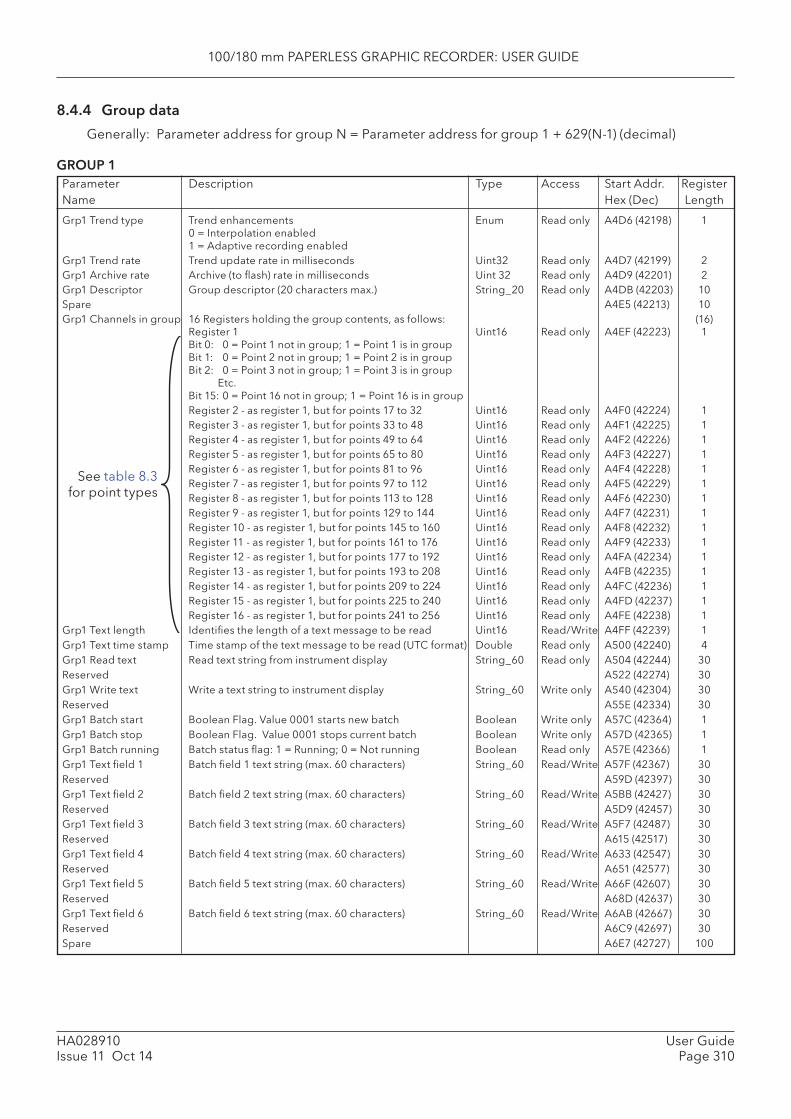
100/180 mm PAPERLESS GRAPHIC RECORDER: USER GUIDE
HA028910Issue 11 Oct 14
User GuidePage 310
8.4.4 Group data
Generally: Parameter address for group N = Parameter address for group 1 + 629(N-1) (decimal)
GROUP 1Parameter Description Type Access Start Addr. RegisterName Hex (Dec) Length
Grp1 Trend type Trend enhancements Enum Read only A4D6 (42198) 10 = Interpolation enabled1 = Adaptive recording enabled
Grp1 Trend rate Trend update rate in milliseconds Uint32 Read only A4D7 (42199) 2Grp1 Archive rate Archive (to fl ash) rate in milliseconds Uint 32 Read only A4D9 (42201) 2Grp1 Descriptor Group descriptor (20 characters max.) String_20 Read only A4DB (42203) 10Spare A4E5 (42213) 10 Grp1 Channels in group 16 Registers holding the group contents, as follows: (16)
Register 1 Uint16 Read only A4EF (42223) 1Bit 0: 0 = Point 1 not in group; 1 = Point 1 is in groupBit 1: 0 = Point 2 not in group; 1 = Point 2 is in groupBit 2: 0 = Point 3 not in group; 1 = Point 3 is in group Etc.Bit 15: 0 = Point 16 not in group; 1 = Point 16 is in group
Register 2 - as register 1, but for points 17 to 32 Uint16 Read only A4F0 (42224) 1 Register 3 - as register 1, but for points 33 to 48 Uint16 Read only A4F1 (42225) 1 Register 4 - as register 1, but for points 49 to 64 Uint16 Read only A4F2 (42226) 1 Register 5 - as register 1, but for points 65 to 80 Uint16 Read only A4F3 (42227) 1 Register 6 - as register 1, but for points 81 to 96 Uint16 Read only A4F4 (42228) 1 Register 7 - as register 1, but for points 97 to 112 Uint16 Read only A4F5 (42229) 1 Register 8 - as register 1, but for points 113 to 128 Uint16 Read only A4F6 (42230) 1 Register 9 - as register 1, but for points 129 to 144 Uint16 Read only A4F7 (42231) 1 Register 10 - as register 1, but for points 145 to 160 Uint16 Read only A4F8 (42232) 1 Register 11 - as register 1, but for points 161 to 176 Uint16 Read only A4F9 (42233) 1 Register 12 - as register 1, but for points 177 to 192 Uint16 Read only A4FA (42234) 1 Register 13 - as register 1, but for points 193 to 208 Uint16 Read only A4FB (42235) 1 Register 14 - as register 1, but for points 209 to 224 Uint16 Read only A4FC (42236) 1 Register 15 - as register 1, but for points 225 to 240 Uint16 Read only A4FD (42237) 1 Register 16 - as register 1, but for points 241 to 256 Uint16 Read only A4FE (42238) 1 Grp1 Text length Identifi es the length of a text message to be read Uint16 Read/Write A4FF (42239) 1Grp1 Text time stamp Time stamp of the text message to be read (UTC format) Double Read only A500 (42240) 4Grp1 Read text Read text string from instrument display String_60 Read only A504 (42244) 30Reserved A522 (42274) 30Grp1 Write text Write a text string to instrument display String_60 Write only A540 (42304) 30Reserved A55E (42334) 30Grp1 Batch start Boolean Flag. Value 0001 starts new batch Boolean Write only A57C (42364) 1Grp1 Batch stop Boolean Flag. Value 0001 stops current batch Boolean Write only A57D (42365) 1Grp1 Batch running Batch status fl ag: 1 = Running; 0 = Not running Boolean Read only A57E (42366) 1Grp1 Text fi eld 1 Batch fi eld 1 text string (max. 60 characters) String_60 Read/Write A57F (42367) 30Reserved A59D (42397) 30Grp1 Text fi eld 2 Batch fi eld 2 text string (max. 60 characters) String_60 Read/Write A5BB (42427) 30Reserved A5D9 (42457) 30Grp1 Text fi eld 3 Batch fi eld 3 text string (max. 60 characters) String_60 Read/Write A5F7 (42487) 30Reserved A615 (42517) 30Grp1 Text fi eld 4 Batch fi eld 4 text string (max. 60 characters) String_60 Read/Write A633 (42547) 30Reserved A651 (42577) 30Grp1 Text fi eld 5 Batch fi eld 5 text string (max. 60 characters) String_60 Read/Write A66F (42607) 30Reserved A68D (42637) 30Grp1 Text fi eld 6 Batch fi eld 6 text string (max. 60 characters) String_60 Read/Write A6AB (42667) 30Reserved A6C9 (42697) 30Spare A6E7 (42727) 100
See table 8.3 for point types
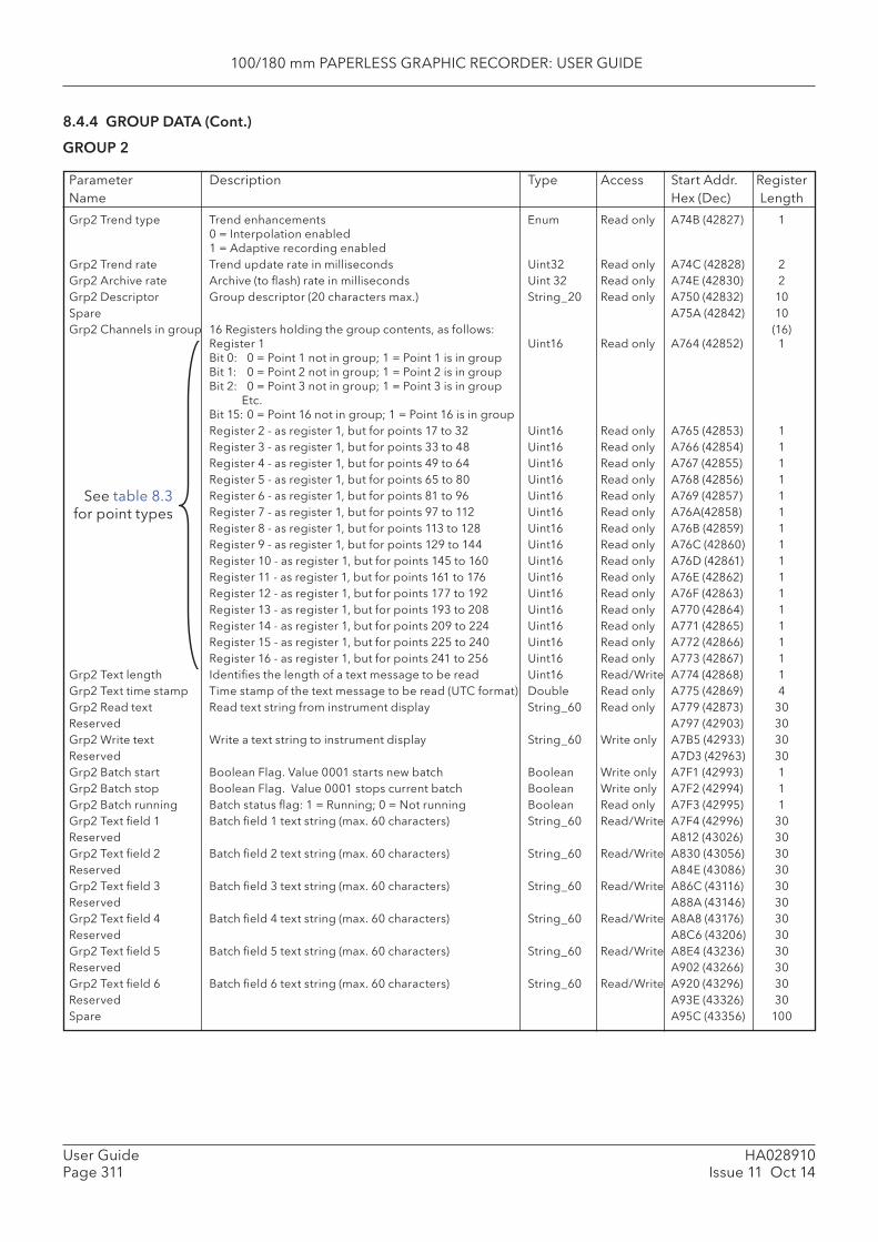
100/180 mm PAPERLESS GRAPHIC RECORDER: USER GUIDE
HA028910Issue 11 Oct 14
User GuidePage 311
8.4.4 GROUP DATA (Cont.)
GROUP 2
Parameter Description Type Access Start Addr. RegisterName Hex (Dec) Length
Grp2 Trend type Trend enhancements Enum Read only A74B (42827) 10 = Interpolation enabled1 = Adaptive recording enabled
Grp2 Trend rate Trend update rate in milliseconds Uint32 Read only A74C (42828) 2Grp2 Archive rate Archive (to fl ash) rate in milliseconds Uint 32 Read only A74E (42830) 2Grp2 Descriptor Group descriptor (20 characters max.) String_20 Read only A750 (42832) 10Spare A75A (42842) 10Grp2 Channels in group 16 Registers holding the group contents, as follows: (16)
Register 1 Uint16 Read only A764 (42852) 1Bit 0: 0 = Point 1 not in group; 1 = Point 1 is in groupBit 1: 0 = Point 2 not in group; 1 = Point 2 is in groupBit 2: 0 = Point 3 not in group; 1 = Point 3 is in group Etc.Bit 15: 0 = Point 16 not in group; 1 = Point 16 is in group
Register 2 - as register 1, but for points 17 to 32 Uint16 Read only A765 (42853) 1 Register 3 - as register 1, but for points 33 to 48 Uint16 Read only A766 (42854) 1 Register 4 - as register 1, but for points 49 to 64 Uint16 Read only A767 (42855) 1 Register 5 - as register 1, but for points 65 to 80 Uint16 Read only A768 (42856) 1 Register 6 - as register 1, but for points 81 to 96 Uint16 Read only A769 (42857) 1 Register 7 - as register 1, but for points 97 to 112 Uint16 Read only A76A(42858) 1 Register 8 - as register 1, but for points 113 to 128 Uint16 Read only A76B (42859) 1 Register 9 - as register 1, but for points 129 to 144 Uint16 Read only A76C (42860) 1 Register 10 - as register 1, but for points 145 to 160 Uint16 Read only A76D (42861) 1 Register 11 - as register 1, but for points 161 to 176 Uint16 Read only A76E (42862) 1 Register 12 - as register 1, but for points 177 to 192 Uint16 Read only A76F (42863) 1 Register 13 - as register 1, but for points 193 to 208 Uint16 Read only A770 (42864) 1 Register 14 - as register 1, but for points 209 to 224 Uint16 Read only A771 (42865) 1 Register 15 - as register 1, but for points 225 to 240 Uint16 Read only A772 (42866) 1 Register 16 - as register 1, but for points 241 to 256 Uint16 Read only A773 (42867) 1Grp2 Text length Identifi es the length of a text message to be read Uint16 Read/Write A774 (42868) 1Grp2 Text time stamp Time stamp of the text message to be read (UTC format) Double Read only A775 (42869) 4Grp2 Read text Read text string from instrument display String_60 Read only A779 (42873) 30Reserved A797 (42903) 30Grp2 Write text Write a text string to instrument display String_60 Write only A7B5 (42933) 30Reserved A7D3 (42963) 30Grp2 Batch start Boolean Flag. Value 0001 starts new batch Boolean Write only A7F1 (42993) 1Grp2 Batch stop Boolean Flag. Value 0001 stops current batch Boolean Write only A7F2 (42994) 1Grp2 Batch running Batch status fl ag: 1 = Running; 0 = Not running Boolean Read only A7F3 (42995) 1Grp2 Text fi eld 1 Batch fi eld 1 text string (max. 60 characters) String_60 Read/Write A7F4 (42996) 30Reserved A812 (43026) 30Grp2 Text fi eld 2 Batch fi eld 2 text string (max. 60 characters) String_60 Read/Write A830 (43056) 30Reserved A84E (43086) 30Grp2 Text fi eld 3 Batch fi eld 3 text string (max. 60 characters) String_60 Read/Write A86C (43116) 30Reserved A88A (43146) 30Grp2 Text fi eld 4 Batch fi eld 4 text string (max. 60 characters) String_60 Read/Write A8A8 (43176) 30Reserved A8C6 (43206) 30Grp2 Text fi eld 5 Batch fi eld 5 text string (max. 60 characters) String_60 Read/Write A8E4 (43236) 30Reserved A902 (43266) 30Grp2 Text fi eld 6 Batch fi eld 6 text string (max. 60 characters) String_60 Read/Write A920 (43296) 30Reserved A93E (43326) 30Spare A95C (43356) 100
See table 8.3 for point types

100/180 mm PAPERLESS GRAPHIC RECORDER: USER GUIDE
HA028910Issue 11 Oct 14
User GuidePage 312
8.4.4 GROUP DATA (Cont.)
GROUP 3
Grp3 Trend type Trend enhancements Enum Read only A9C0 (43456) 10 = Interpolation enabled1 = Adaptive recording enabled
Grp3 Trend rate Trend update rate in milliseconds Uint32 Read only A9C1 (43457) 2Grp3 Archive rate Archive (to fl ash) rate in milliseconds Uint 32 Read only A9C3 (43459) 2Grp3 Descriptor Group descriptor (20 characters max.) String_20 Read only A9C5 (43461) 10Spare A9CF (43471) 10Grp3 Channels in group 16 Registers holding the group contents, as follows: (16)
Register 1 Uint16 Read only A9D9 (43481) 1Bit 0: 0 = Point 1 not in group; 1 = Point 1 is in groupBit 1: 0 = Point 2 not in group; 1 = Point 2 is in groupBit 2: 0 = Point 3 not in group; 1 = Point 3 is in group Etc.Bit 15: 0 = Point 16 not in group; 1 = Point 16 is in group
Register 2 - as register 1, but for points 17 to 32 Uint16 Read only A9DA (42482) 1 Register 3 - as register 1, but for points 33 to 48 Uint16 Read only A9DB (42483) 1 Register 4 - as register 1, but for points 49 to 64 Uint16 Read only A9DC (42484) 1 Register 5 - as register 1, but for points 65 to 80 Uint16 Read only A9DD (42485) 1 Register 6 - as register 1, but for points 81 to 96 Uint16 Read only A9DE (42486) 1 Register 7 - as register 1, but for points 97 to 112 Uint16 Read only A9DF (42487) 1 Register 8 - as register 1, but for points 113 to 128 Uint16 Read only A9E0 (42488) 1 Register 9 - as register 1, but for points 129 to 144 Uint16 Read only A9E1 (42489) 1 Register 10 - as register 1, but for points 145 to 160 Uint16 Read only A9E2 (42490) 1 Register 11 - as register 1, but for points 161 to 176 Uint16 Read only A9E3 (42491) 1 Register 12 - as register 1, but for points 177 to 192 Uint16 Read only A9E4 (42492) 1 Register 13 - as register 1, but for points 193 to 208 Uint16 Read only A9E5 (42493) 1 Register 14 - as register 1, but for points 209 to 224 Uint16 Read only A9E6 (42494) 1 Register 15 - as register 1, but for points 225 to 240 Uint16 Read only A9E7 (42495) 1 Register 16 - as register 1, but for points 241 to 256 Uint16 Read only A9E8 (43496) 1Grp3 Text length Identifi es the length of a text message to be read Uint16 Read/Write A9E9 (43497) 1Grp3 Text time stamp Time stamp of the text message to be read (UTC format) Double Read only A9EA (43498) 4Grp3 Read text Read text string from instrument display String_60 Read only A9EE (43502) 30Reserved AA0C (43532 30Grp3 Write text Write a text string to instrument display String_120 Write only AA2A (43562) 60Reserved AA48 (43592) 30Grp3 Batch start Boolean Flag. Value 0001 starts new batch Boolean Write only AA66 (43622) 1Grp3 Batch stop Boolean Flag. Value 0001 stops current batch Boolean Write only AA67 (43623) 1Grp3 Batch running Batch status fl ag: 1 = Running; 0 = Not running Boolean Read only AA68 (43624) 1Grp3 Text fi eld 1 Batch fi eld 1 text string (max. 60 characters) String_60 Read/Write AA69 (43625) 30Reserved AA87 (43655) 30Grp3 Text fi eld 2 Batch fi eld 2 text string (max. 60 characters) String_60 Read/Write AAA5 (43685) 30Reserved AAC3 (43715) 30Grp3 Text fi eld 3 Batch fi eld 3 text string (max. 60 characters) String_60 Read/Write AAE1 (43745) 30Reserved AAFF (43775) 30Grp3 Text fi eld 4 Batch fi eld 4 text string (max. 60 characters) String_60 Read/Write AB1D (43805) 30Reserved AB3B (43835) 30Grp3 Text fi eld 5 Batch fi eld 5 text string (max. 60 characters) String_60 Read/Write AB59 (43865) 30Reserved AB77 (43895) 30Grp3 Text fi eld 6 Batch fi eld 6 text string (max. 60 characters) String_60 Read/Write AB95 (43925) 30Reserved ABB3 (43955) 30Spare ABD1 (43985) 100
Parameter Description Type Access Start Addr. RegisterName Hex (Dec) Length
See table 8.3 for point types
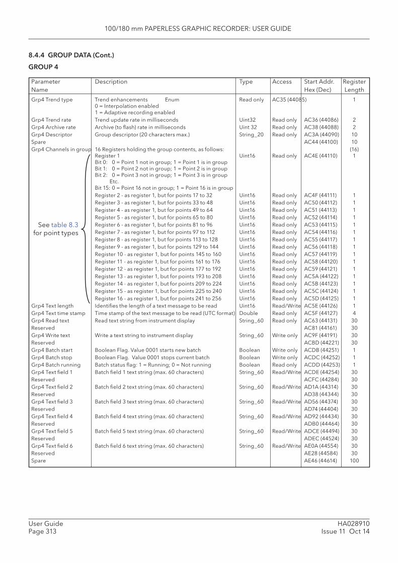
100/180 mm PAPERLESS GRAPHIC RECORDER: USER GUIDE
HA028910Issue 11 Oct 14
User GuidePage 313
8.4.4 GROUP DATA (Cont.)
GROUP 4
Parameter Description Type Access Start Addr. RegisterName Hex (Dec) Length
See table 8.3 for point types
Grp4 Trend type Trend enhancements Enum Read only AC35 (44085) 10 = Interpolation enabled1 = Adaptive recording enabled
Grp4 Trend rate Trend update rate in milliseconds Uint32 Read only AC36 (44086) 2Grp4 Archive rate Archive (to fl ash) rate in milliseconds Uint 32 Read only AC38 (44088) 2Grp4 Descriptor Group descriptor (20 characters max.) String_20 Read only AC3A (44090) 10Spare AC44 (44100) 10Grp4 Channels in group 16 Registers holding the group contents, as follows: (16)
Register 1 Uint16 Read only AC4E (44110) 1Bit 0: 0 = Point 1 not in group; 1 = Point 1 is in groupBit 1: 0 = Point 2 not in group; 1 = Point 2 is in groupBit 2: 0 = Point 3 not in group; 1 = Point 3 is in group Etc.Bit 15: 0 = Point 16 not in group; 1 = Point 16 is in group
Register 2 - as register 1, but for points 17 to 32 Uint16 Read only AC4F (44111) 1 Register 3 - as register 1, but for points 33 to 48 Uint16 Read only AC50 (44112) 1 Register 4 - as register 1, but for points 49 to 64 Uint16 Read only AC51 (44113) 1 Register 5 - as register 1, but for points 65 to 80 Uint16 Read only AC52 (44114) 1 Register 6 - as register 1, but for points 81 to 96 Uint16 Read only AC53 (44115) 1 Register 7 - as register 1, but for points 97 to 112 Uint16 Read only AC54 (44116) 1 Register 8 - as register 1, but for points 113 to 128 Uint16 Read only AC55 (44117) 1 Register 9 - as register 1, but for points 129 to 144 Uint16 Read only AC56 (44118) 1 Register 10 - as register 1, but for points 145 to 160 Uint16 Read only AC57 (44119) 1 Register 11 - as register 1, but for points 161 to 176 Uint16 Read only AC58 (44120) 1 Register 12 - as register 1, but for points 177 to 192 Uint16 Read only AC59 (44121) 1 Register 13 - as register 1, but for points 193 to 208 Uint16 Read only AC5A (44122) 1 Register 14 - as register 1, but for points 209 to 224 Uint16 Read only AC5B (44123) 1 Register 15 - as register 1, but for points 225 to 240 Uint16 Read only AC5C (44124) 1 Register 16 - as register 1, but for points 241 to 256 Uint16 Read only AC5D (44125) 1Grp4 Text length Identifi es the length of a text message to be read Uint16 Read/Write AC5E (44126) 1Grp4 Text time stamp Time stamp of the text message to be read (UTC format) Double Read only AC5F (44127) 4Grp4 Read text Read text string from instrument display String_60 Read only AC63 (44131) 30Reserved AC81 (44161) 30Grp4 Write text Write a text string to instrument display String_60 Write only AC9F (44191) 30Reserved ACBD (44221) 30Grp4 Batch start Boolean Flag. Value 0001 starts new batch Boolean Write only ACDB (44251) 1Grp4 Batch stop Boolean Flag. Value 0001 stops current batch Boolean Write only ACDC (44252) 1Grp4 Batch running Batch status fl ag: 1 = Running; 0 = Not running Boolean Read only ACDD (44253) 1Grp4 Text fi eld 1 Batch fi eld 1 text string (max. 60 characters) String_60 Read/Write ACDE (44254) 30Reserved ACFC (44284) 30Grp4 Text fi eld 2 Batch fi eld 2 text string (max. 60 characters) String_60 Read/Write AD1A (44314) 30Reserved AD38 (44344) 30Grp4 Text fi eld 3 Batch fi eld 3 text string (max. 60 characters) String_60 Read/Write AD56 (44374) 30Reserved AD74 (44404) 30Grp4 Text fi eld 4 Batch fi eld 4 text string (max. 60 characters) String_60 Read/Write AD92 (44434) 30Reserved ADB0 (44464) 30Grp4 Text fi eld 5 Batch fi eld 5 text string (max. 60 characters) String_60 Read/Write ADCE (44494) 30Reserved ADEC (44524) 30Grp4 Text fi eld 6 Batch fi eld 6 text string (max. 60 characters) String_60 Read/Write AE0A (44554) 30Reserved AE28 (44584) 30Spare AE46 (44614) 100

100/180 mm PAPERLESS GRAPHIC RECORDER: USER GUIDE
HA028910Issue 11 Oct 14
User GuidePage 314
8.4.4 GROUP DATA (Cont.)
GROUP 5
Parameter Description Type Access Start Addr. RegisterName Hex (Dec) Length
See table 8.3 for point types
Grp5 Trend type Trend enhancements Enum Read only AEAA (44714) 10 = Interpolation enabled1 = Adaptive recording enabled
Grp5 Trend rate Trend update rate in milliseconds Uint32 Read only AEAB (44715) 2Grp5 Archive rate Archive (to fl ash) rate in milliseconds Uint 32 Read only AEAD (44717) 2Grp5 Descriptor Group descriptor (20 characters max.) String_20 Read only AEAF (44719) 10Spare AEB9 (44729) 10Grp5 Channels in group 16 Registers holding the group contents, as follows: (16)
Register 1 Uint16 Read only AEC3 (44739) 1Bit 0: 0 = Point 1 not in group; 1 = Point 1 is in groupBit 1: 0 = Point 2 not in group; 1 = Point 2 is in groupBit 2: 0 = Point 3 not in group; 1 = Point 3 is in group Etc.Bit 15: 0 = Point 16 not in group; 1 = Point 16 is in group
Register 2 - as register 1, but for points 17 to 32 Uint16 Read only AEC4 (44740) 1 Register 3 - as register 1, but for points 33 to 48 Uint16 Read only AEC5 (44741) 1 Register 4 - as register 1, but for points 49 to 64 Uint16 Read only AEC6 (44742) 1 Register 5 - as register 1, but for points 65 to 80 Uint16 Read only AEC7 (44743) 1 Register 6 - as register 1, but for points 81 to 96 Uint16 Read only AEC8 (44744) 1 Register 7 - as register 1, but for points 97 to 112 Uint16 Read only AEC9 (44745) 1 Register 8 - as register 1, but for points 113 to 128 Uint16 Read only AECA (44746) 1 Register 9 - as register 1, but for points 129 to 144 Uint16 Read only AECB (44747) 1 Register 10 - as register 1, but for points 145 to 160 Uint16 Read only AECC (44748) 1 Register 11 - as register 1, but for points 161 to 176 Uint16 Read only AECD (44749) 1 Register 12 - as register 1, but for points 177 to 192 Uint16 Read only AECE (44750) 1 Register 13 - as register 1, but for points 193 to 208 Uint16 Read only AECF (44751) 1 Register 14 - as register 1, but for points 209 to 224 Uint16 Read only AED0 (44752) 1 Register 15 - as register 1, but for points 225 to 240 Uint16 Read only AED1 (42253) 1 Register 16 - as register 1, but for points 241 to 256 Uint16 Read only AED2 (44754) 1Grp5 Text length Identifi es the length of a text message to be read Uint16 Read/Write AED3 (44755) 1Grp5 Text time stamp Time stamp of the text message to be read (UTC format) Double Read only AED4 (44756) 4Grp5 Read text Read text string from instrument display String_60 Read only AED8 (44760) 30Reserved AEF6 (44790) 30Grp5 Write text Write a text string to instrument display String_60 Write only AF14 (44820) 30Reserved AF32 (44850) 30Grp5 Batch start Boolean Flag. Value 0001 starts new batch Boolean Write only AF50 (44880) 1Grp5 Batch stop Boolean Flag. Value 0001 stops current batch Boolean Write only AF51 (44881) 1Grp5 Batch running Batch status fl ag: 1 = Running; 0 = Not running Boolean Read only AF52 (44882) 1Grp5 Text fi eld 1 Batch fi eld 1 text string (max. 60 characters) String_60 Read/Write AF53 (44883) 30Reserved AF71 (44913) 30Grp5 Text fi eld 2 Batch fi eld 2 text string (max. 60 characters) String_60 Read/Write AF8F (44943) 30Reserved AFAD (44973) 30Grp5 Text fi eld 3 Batch fi eld 3 text string (max. 60 characters) String_60 Read/Write AFCB (45003) 30Reserved AFE9 (45033) 30Grp5 Text fi eld 4 Batch fi eld 4 text string (max. 60 characters) String_60 Read/Write B007 (45063) 30Reserved B025 (45093) 30Grp5 Text fi eld 5 Batch fi eld 5 text string (max. 60 characters) String_60 Read/Write B043 (45123) 30Reserved B061 (45153) 30Grp5 Text fi eld 6 Batch fi eld 6 text string (max. 60 characters) String_60 Read/Write B08F (45183) 30Reserved B09D (45213) 30Spare B0BB (45243) 100

100/180 mm PAPERLESS GRAPHIC RECORDER: USER GUIDE
HA028910Issue 11 Oct 14
User GuidePage 315
8.4.4 GROUP DATA (Cont.)
GROUP 6
Parameter Description Type Access Start Addr. RegisterName Hex (Dec) Length
See table 8.3 for point types
Grp6 Trend type Trend enhancements Enum Read only B11F (45343) 10 = Interpolation enabled1 = Adaptive recording enabled
Grp6 Trend rate Trend update rate in milliseconds Uint32 Read only B120 (45344) 2Grp6 Archive rate Archive (to fl ash) rate in milliseconds Uint 32 Read only B122 (45346) 2Grp6 Descriptor Group descriptor (20 characters max.) String_20 Read only B124 (45348) 10Spare B12E (45358) 10Grp6 Channels in group 16 Registers holding the group contents, as follows: (16)
Register 1 Uint16 Read only B138 (45368) 1Bit 0: 0 = Point 1 not in group; 1 = Point 1 is in groupBit 1: 0 = Point 2 not in group; 1 = Point 2 is in groupBit 2: 0 = Point 3 not in group; 1 = Point 3 is in group Etc.Bit 15: 0 = Point 16 not in group; 1 = Point 16 is in group
Register 2 - as register 1, but for points 17 to 32 Uint16 Read only B139 (45369) 1 Register 3 - as register 1, but for points 33 to 48 Uint16 Read only B13A (45370) 1 Register 4 - as register 1, but for points 49 to 64 Uint16 Read only B13B (45371) 1 Register 5 - as register 1, but for points 65 to 80 Uint16 Read only B13C (45372) 1 Register 6 - as register 1, but for points 81 to 96 Uint16 Read only B13D (45373) 1 Register 7 - as register 1, but for points 97 to 112 Uint16 Read only B13E (45374) 1 Register 8 - as register 1, but for points 113 to 128 Uint16 Read only B13F (45375) 1 Register 9 - as register 1, but for points 129 to 144 Uint16 Read only B140 (45376) 1 Register 10 - as register 1, but for points 145 to 160 Uint16 Read only B141 (45377) 1 Register 11 - as register 1, but for points 161 to 176 Uint16 Read only B142 (45378) 1 Register 12 - as register 1, but for points 177 to 192 Uint16 Read only B143 (45379) 1 Register 13 - as register 1, but for points 193 to 208 Uint16 Read only B144 (45380) 1 Register 14 - as register 1, but for points 209 to 224 Uint16 Read only B145 (45381) 1 Register 15 - as register 1, but for points 225 to 240 Uint16 Read only B146 (45382) 1 Register 16 - as register 1, but for points 241 to 256 Uint16 Read only B147 (45383) 1Grp6 Text length Identifi es the length of a text message to be read Uint16 Read/Write B148 (45384) 1Grp6 Text time stamp Time stamp of the text message to be read (UTC format) Double Read only B149 (45385) 4Grp6 Read text Read text string from instrument display String_60 Read only B14D (45389) 30Reserved B16B (45419) 30Grp6 Write text Write a text string to instrument display String_60 Write only B189 (45449) 30Reserved B1A7 (45479) 30Grp6 Batch start Boolean Flag. Value 0001 starts new batch Boolean Write only B1C5 (45509) 1Grp6 Batch stop Boolean Flag. Value 0001 stops current batch Boolean Write only B1C6 (45510) 1Grp6 Batch running Batch status fl ag: 1 = Running; 0 = Not running Boolean Read only B1C7 (45511) 1Grp6 Text fi eld 1 Batch fi eld 1 text string (max. 60 characters) String_60 Read/Write B1C8 (45512) 30Reserved B1E6 (45542) 30Grp6 Text fi eld 2 Batch fi eld 2 text string (max. 60 characters) String_60 Read/Write B204 (45572) 30Reserved B222 (45602) 30Grp6 Text fi eld 3 Batch fi eld 3 text string (max. 60 characters) String_60 Read/Write B240 (45632) 30Reserved B25E (45662) 30Grp6 Text fi eld 4 Batch fi eld 4 text string (max. 60 characters) String_60 Read/Write B27C (45692) 30Reserved B29A (45722) 30Grp6 Text fi eld 5 Batch fi eld 5 text string (max. 60 characters) String_60 Read/Write B2B8 (45752) 30Reserved B2D6 (45782) 30Grp6 Text fi eld 6 Batch fi eld 6 text string (max. 60 characters) String_60 Read/Write B2F4 (45812) 30Reserved B312 (45842) 30Spare B330 (45872) 100
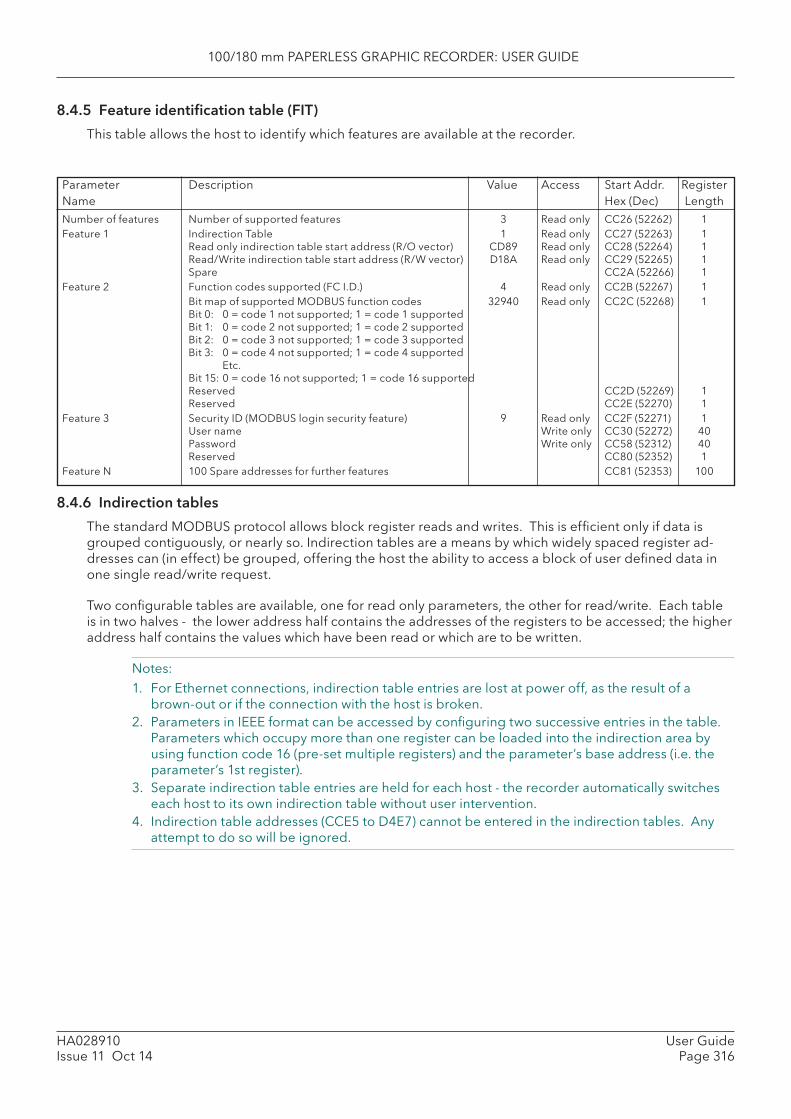
100/180 mm PAPERLESS GRAPHIC RECORDER: USER GUIDE
HA028910Issue 11 Oct 14
User GuidePage 316
8.4.5 Feature identifi cation table ( FIT)
This table allows the host to identify which features are available at the recorder.
Number of features Number of supported features 3 Read only CC26 (52262) 1Feature 1 Indirection Table 1 Read only CC27 (52263) 1
Read only indirection table start address (R/O vector) CD89 Read only CC28 (52264) 1Read/Write indirection table start address (R/W vector) D18A Read only CC29 (52265) 1Spare CC2A (52266) 1
Feature 2 Function codes supported (FC I.D.) 4 Read only CC2B (52267) 1 Bit map of supported MODBUS function codes 32940 Read only CC2C (52268) 1
Bit 0: 0 = code 1 not supported; 1 = code 1 supportedBit 1: 0 = code 2 not supported; 1 = code 2 supportedBit 2: 0 = code 3 not supported; 1 = code 3 supportedBit 3: 0 = code 4 not supported; 1 = code 4 supported Etc.Bit 15: 0 = code 16 not supported; 1 = code 16 supportedReserved CC2D (52269) 1Reserved CC2E (52270) 1
Feature 3 Security ID (MODBUS login security feature) 9 Read only CC2F (52271) 1User name Write only CC30 (52272) 40Password Write only CC58 (52312) 40Reserved CC80 (52352) 1
Feature N 100 Spare addresses for further features CC81 (52353) 100
8.4.6 Indirection tables
The standard MODBUS protocol allows block register reads and writes. This is effi cient only if data is grouped contiguously, or nearly so. Indirection tables are a means by which widely spaced register ad-dresses can (in effect) be grouped, offering the host the ability to access a block of user defi ned data in one single read/write request.
Two confi gurable tables are available, one for read only parameters, the other for read/write. Each table is in two halves - the lower address half contains the addresses of the registers to be accessed; the higher address half contains the values which have been read or which are to be written.
Notes: 1. For Ethernet connections, indirection table entries are lost at power off, as the result of a
brown-out or if the connection with the host is broken. 2. Parameters in IEEE format can be accessed by confi guring two successive entries in the table.
Parameters which occupy more than one register can be loaded into the indirection area by using function code 16 (pre-set multiple registers) and the parameter’s base address (i.e. the parameter’s 1st register).
3. Separate indirection table entries are held for each host - the recorder automatically switches each host to its own indirection table without user intervention.
4. Indirection table addresses (CCE5 to D4E7) cannot be entered in the indirection tables. Any attempt to do so will be ignored.
Parameter Description Value Access Start Addr. RegisterName Hex (Dec) Length
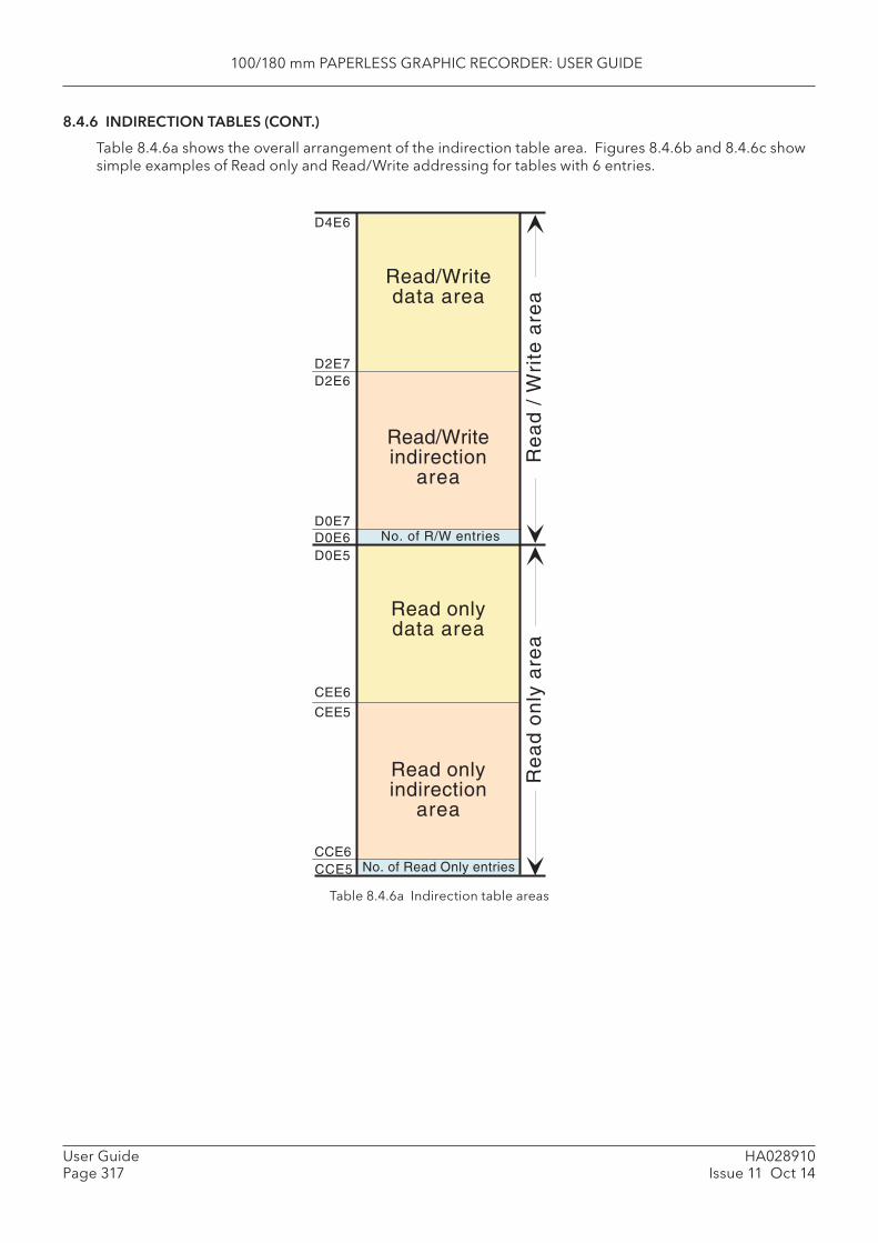
100/180 mm PAPERLESS GRAPHIC RECORDER: USER GUIDE
HA028910Issue 11 Oct 14
User GuidePage 317
8.4.6 INDIRECTION TABLES (CONT.)
Table 8.4.6a shows the overall arrangement of the indirection table area. Figures 8.4.6b and 8.4.6c show simple examples of Read only and Read/Write addressing for tables with 6 entries.
Read onlyindirection
area
Read onlydata area
Read/Writeindirection
area
Read/Writedata area
CCE5CCE6
CEE6
CEE5
D0E5D0E6D0E7
D2E7D2E6
D4E6
No. of R/W entries
No. of Read Only entries
Re
ad
on
ly a
rea
Re
ad
/ W
rite
are
a
Table 8.4.6a Indirection table areas
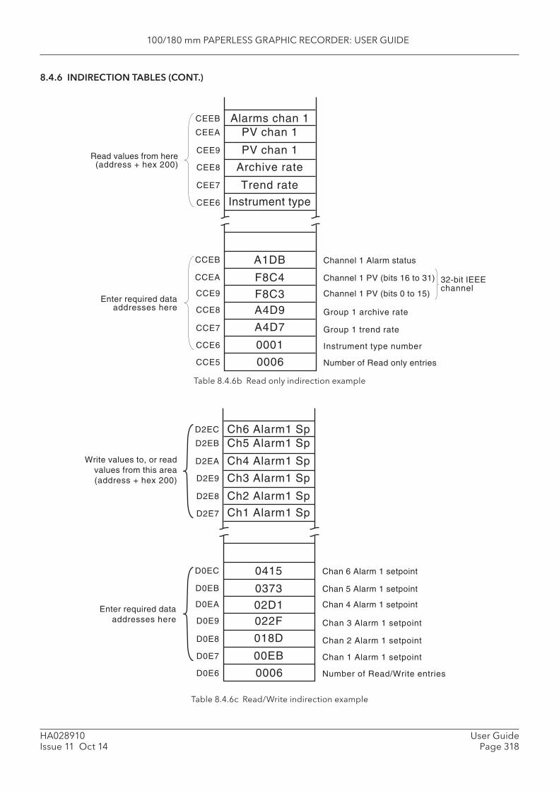
100/180 mm PAPERLESS GRAPHIC RECORDER: USER GUIDE
HA028910Issue 11 Oct 14
User GuidePage 318
CCE5 0006
CCE6
CCE7
CCE8
CCE9
CCEA
0001
A4D7
A4D9F8C3
F8C4
A1DB
Instrument type number
Group 1 trend rate
Group 1 archive rate
Channel 1 PV (bits 0 to 15)
Channel 1 PV (bits 16 to 31)
Channel 1 Alarm statusCCEB
Number of Read only entries
CEE6 Instrument type
Trend rateCEE7
Archive rateCEE8
PV chan 1CEE9
PV chan 1CEEA
Alarms chan 1CEEB
Enter required dataaddresses here
Read values from here(address + hex 200)
32-bit IEEEchannel
D0E6 0006
D0E7
D0E8
D0E9
D0EA
D0EB
00EB
018D
022F02D1
0373
0415
Chan 1 Alarm 1 setpoint
Chan 2 Alarm 1 setpoint
Chan 3 Alarm 1 setpoint
Chan 4 Alarm 1 setpoint
Chan 5 Alarm 1 setpoint
Chan 6 Alarm 1 setpointD0EC
Number of Read/Write entries
D2E7 Ch1 Alarm1 Sp
Ch2 Alarm1 SpD2E8
Ch3 Alarm1 SpD2E9
Ch4 Alarm1 SpD2EA
Ch5 Alarm1 SpD2EB
Ch6 Alarm1 SpD2EC
Enter required dataaddresses here
Write values to, or readvalues from this area(address + hex 200)
8.4.6 INDIRECTION TABLES (CONT.)
Table 8.4.6b Read only indirection example
Table 8.4.6c Read/Write indirection example
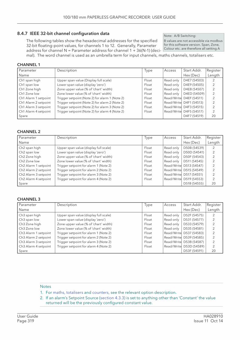
100/180 mm PAPERLESS GRAPHIC RECORDER: USER GUIDE
HA028910Issue 11 Oct 14
User GuidePage 319
8.4.7 IEEE 32-bit channel confi guration data
The following tables show the hexadecimal addresses for the specifi ed 32-bit fl oating-point values, for channels 1 to 12. Generally, Parameter address for channel N = Parameter address for channel 1 + 36(N-1) (deci-mal). The word channel is used as an umbrella term for input channels, maths channels, totalisers etc.
CHANNEL 1
Note: A/B Switching:
B values are not accessible via modbus for this software version. Span, Zone, Colour etc. are therefore all setting A
Notes1. For maths, totalisers and counters, see the relevant option description.2. If an alarm’s Setpoint Source (section 4.3.3) is set to anything other than ‘Constant’ the value
returned will be the previously confi gured constant value.
Parameter Description Type Access Start Addr. RegisterName Hex (Dec) Length
Parameter Description Type Access Start Addr. RegisterName Hex (Dec) Length
Parameter Description Type Access Start Addr. RegisterName Hex (Dec) Length
Ch1 span high Upper span value (Display full scale) Float Read only D4E7 (54503) 2Ch1 span low Lower span value (display ‘zero’) Float Read only D4E9 (54505) 2Ch1 Zone high Zone upper value (% of ‘chart’ width) Float Read only D4EB (54507) 2Ch1 Zone low Zone lower value (% of ‘chart’ width) Float Read only D4ED (54509) 2Ch1 Alarm 1 setpoint Trigger setpoint (Note 2) for alarm 1 (Note 2) Float Read/Write D4EF (54511) 2Ch1 Alarm 2 setpoint Trigger setpoint (Note 2) for alarm 2 (Note 2) Float Read/Write D4F1 (54513) 2Ch1 Alarm 3 setpoint Trigger setpoint (Note 2) for alarm 3 (Note 2) Float Read/Write D4F3 (54515) 2Ch1 Alarm 4 setpoint Trigger setpoint (Note 2) for alarm 4 (Note 2) Float Read/Write D4F5 (54517) 2Spare D4F7 (54519) 20
CHANNEL 2
Ch2 span high Upper span value (display full scale) Float Read only D50B (54539) 2Ch2 span low Lower span value (display ‘zero’) Float Read only D50D (54541) 2Ch2 Zone high Zone upper value (% of ‘chart’ width) Float Read only D50F (54543) 2Ch2 Zone low Zone lower value (% of ‘chart’ width) Float Read only D511 (54545) 2Ch2 Alarm 1 setpoint Trigger setpoint for alarm 1 (Note 2) Float Read/Write D513 (54547) 2Ch2 Alarm 2 setpoint Trigger setpoint for alarm 2 (Note 2) Float Read/Write D515 (54549) 2Ch2 Alarm 3 setpoint Trigger setpoint for alarm 3 (Note 2) Float Read/Write D517 (54551) 2Ch2 Alarm 4 setpoint Trigger setpoint for alarm 4 (Note 2) Float Read/Write D519 (54553) 2Spare D51B (54555) 20
CHANNEL 3
Ch3 span high Upper span value (display full scale) Float Read only D52F (54575) 2Ch3 span low Lower span value (display ‘zero’) Float Read only D531 (54577) 2Ch3 Zone high Zone upper value (% of ‘chart’ width) Float Read only D533 (54579) 2Ch3 Zone low Zone lower value (% of ‘chart’ width) Float Read only D535 (54581) 2Ch3 Alarm 1 setpoint Trigger setpoint for alarm 1 (Note 2) Float Read/Write D537 (54583) 2Ch3 Alarm 2 setpoint Trigger setpoint for alarm 2 (Note 2) Float Read/Write D539 (54585) 2Ch3 Alarm 3 setpoint Trigger setpoint for alarm 3 (Note 2) Float Read/Write D53B (54587) 2Ch3 Alarm 4 setpoint Trigger setpoint for alarm 4 (Note 2) Float Read/Write D53D (54589) 2Spare D53F (54591) 20
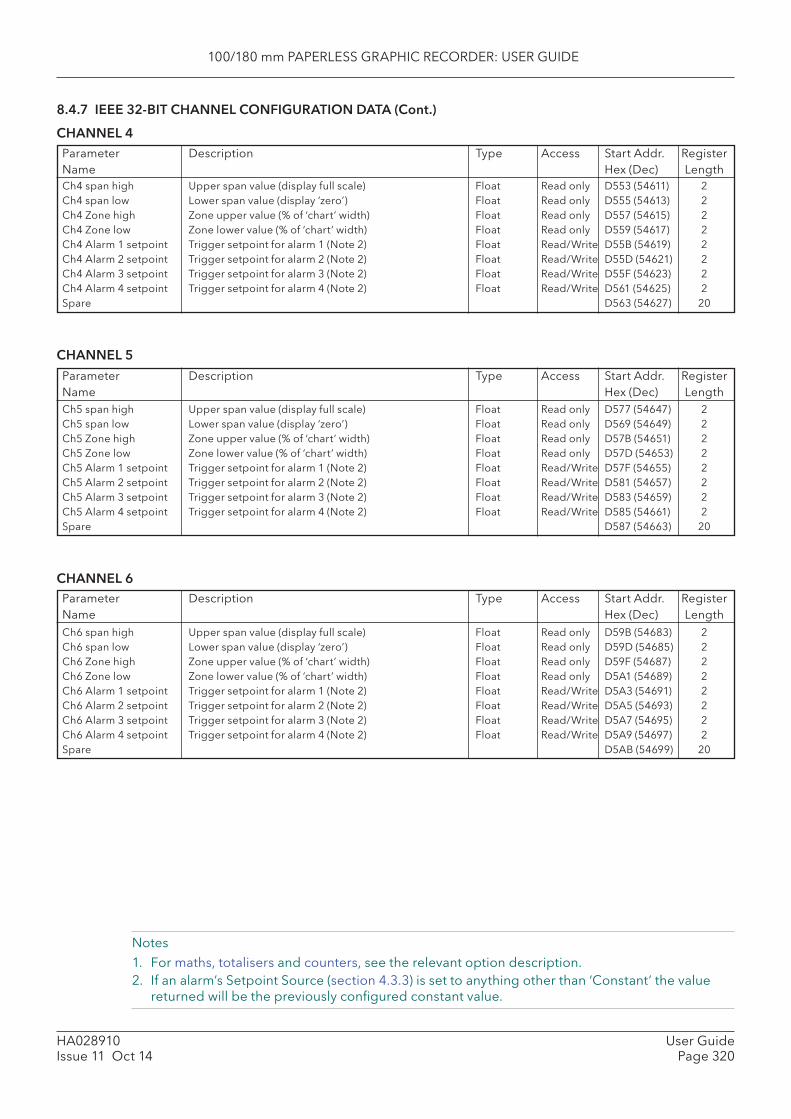
100/180 mm PAPERLESS GRAPHIC RECORDER: USER GUIDE
HA028910Issue 11 Oct 14
User GuidePage 320
8.4.7 IEEE 32-BIT CHANNEL CONFIGURATION DATA (Cont.)
CHANNEL 4
Notes1. For maths, totalisers and counters, see the relevant option description.2. If an alarm’s Setpoint Source (section 4.3.3) is set to anything other than ‘Constant’ the value
returned will be the previously confi gured constant value.
Ch4 span high Upper span value (display full scale) Float Read only D553 (54611) 2Ch4 span low Lower span value (display ‘zero’) Float Read only D555 (54613) 2Ch4 Zone high Zone upper value (% of ‘chart’ width) Float Read only D557 (54615) 2Ch4 Zone low Zone lower value (% of ‘chart’ width) Float Read only D559 (54617) 2Ch4 Alarm 1 setpoint Trigger setpoint for alarm 1 (Note 2) Float Read/Write D55B (54619) 2Ch4 Alarm 2 setpoint Trigger setpoint for alarm 2 (Note 2) Float Read/Write D55D (54621) 2Ch4 Alarm 3 setpoint Trigger setpoint for alarm 3 (Note 2) Float Read/Write D55F (54623) 2Ch4 Alarm 4 setpoint Trigger setpoint for alarm 4 (Note 2) Float Read/Write D561 (54625) 2Spare D563 (54627) 20
CHANNEL 5
Ch5 span high Upper span value (display full scale) Float Read only D577 (54647) 2Ch5 span low Lower span value (display ‘zero’) Float Read only D569 (54649) 2Ch5 Zone high Zone upper value (% of ‘chart’ width) Float Read only D57B (54651) 2Ch5 Zone low Zone lower value (% of ‘chart’ width) Float Read only D57D (54653) 2Ch5 Alarm 1 setpoint Trigger setpoint for alarm 1 (Note 2) Float Read/Write D57F (54655) 2Ch5 Alarm 2 setpoint Trigger setpoint for alarm 2 (Note 2) Float Read/Write D581 (54657) 2Ch5 Alarm 3 setpoint Trigger setpoint for alarm 3 (Note 2) Float Read/Write D583 (54659) 2Ch5 Alarm 4 setpoint Trigger setpoint for alarm 4 (Note 2) Float Read/Write D585 (54661) 2Spare D587 (54663) 20
CHANNEL 6
Parameter Description Type Access Start Addr. RegisterName Hex (Dec) Length
Parameter Description Type Access Start Addr. RegisterName Hex (Dec) Length
Parameter Description Type Access Start Addr. RegisterName Hex (Dec) LengthCh6 span high Upper span value (display full scale) Float Read only D59B (54683) 2Ch6 span low Lower span value (display ‘zero’) Float Read only D59D (54685) 2Ch6 Zone high Zone upper value (% of ‘chart’ width) Float Read only D59F (54687) 2Ch6 Zone low Zone lower value (% of ‘chart’ width) Float Read only D5A1 (54689) 2Ch6 Alarm 1 setpoint Trigger setpoint for alarm 1 (Note 2) Float Read/Write D5A3 (54691) 2Ch6 Alarm 2 setpoint Trigger setpoint for alarm 2 (Note 2) Float Read/Write D5A5 (54693) 2Ch6 Alarm 3 setpoint Trigger setpoint for alarm 3 (Note 2) Float Read/Write D5A7 (54695) 2Ch6 Alarm 4 setpoint Trigger setpoint for alarm 4 (Note 2) Float Read/Write D5A9 (54697) 2Spare D5AB (54699) 20

100/180 mm PAPERLESS GRAPHIC RECORDER: USER GUIDE
HA028910Issue 11 Oct 14
User GuidePage 321
8.4.7 IEEE 32-BIT CHANNEL CONFIGURATION DATA (Cont.)
CHANNEL 7
Notes1. For maths, totalisers and counters, see the relevant option description.2. If an alarm’s Setpoint Source (section 4.3.3) is set to anything other than ‘Constant’ the value
returned will be the previously confi gured constant value.
Parameter Description Type Access Start Addr. RegisterName Hex (Dec) Length
Parameter Description Type Access Start Addr. RegisterName Hex (Dec) Length
Parameter Description Type Access Start Addr. RegisterName Hex (Dec) Length
Ch7 span high Upper span value (display full scale) Float Read only D5BF (54719) 2Ch7 span low Lower span value (display ‘zero’) Float Read only D5C1 (54721) 2Ch7 Zone high Zone upper value (% of ‘chart’ width) Float Read only D5C3 (54723) 2Ch7 Zone low Zone lower value (% of ‘chart’ width) Float Read only D5C5 (54725) 2Ch7 Alarm 1 setpoint Trigger setpoint for alarm 1 (Note 2) Float Read/Write D5C7 (54727) 2Ch7 Alarm 2 setpoint Trigger setpoint for alarm 2 (Note 2) Float Read/Write D5C9 (54729) 2Ch7 Alarm 3 setpoint Trigger setpoint for alarm 3 (Note 2) Float Read/Write D5CB (54731) 2Ch7 Alarm 4 setpoint Trigger setpoint for alarm 4 (Note 2) Float Read/Write D5CD (54733) 2Spare D5CF (54735) 20
CHANNEL 8
Ch8 span high Upper span value (display full scale) Float Read only D5E3 (54755) 2Ch8 span low Lower span value (display ‘zero’) Float Read only D5E5 (54757) 2Ch8 Zone high Zone upper value (% of ‘chart’ width) Float Read only D5E7 (54759) 2Ch8 Zone low Zone lower value (% of ‘chart’ width) Float Read only D5E9 (54761) 2Ch8 Alarm 1 setpoint Trigger setpoint for alarm 1 (Note 2) Float Read/Write D5EB (54763) 2Ch8 Alarm 2 setpoint Trigger setpoint for alarm 2 (Note 2) Float Read/Write D5ED (54765) 2Ch8 Alarm 3 setpoint Trigger setpoint for alarm 3 (Note 2) Float Read/Write D5EF (54767) 2Ch8 Alarm 4 setpoint Trigger setpoint for alarm 4 (Note 2) Float Read/Write D5F1 (54769) 2Spare D5F3 (54771) 20
CHANNEL 9
Ch9 span high Upper span value (display full scale) Float Read only D607 (54791) 2Ch9 span low Lower span value (display ‘zero’) Float Read only D609 (54793) 2Ch9 Zone high Zone upper value (% of ‘chart’ width) Float Read only D60B (54795) 2Ch9 Zone low Zone lower value (% of ‘chart’ width) Float Read only D60D (54797) 2Ch9 Alarm 1 setpoint Trigger setpoint for alarm 1 (Note 2) Float Read/Write D60F (54799) 2Ch9 Alarm 2 setpoint Trigger setpoint for alarm 2 (Note 2) Float Read/Write D611 (54801) 2Ch9 Alarm 3 setpoint Trigger setpoint for alarm 3 (Note 2) Float Read/Write D613 (54803) 2Ch9 Alarm 4 setpoint Trigger setpoint for alarm 4 (Note 2) Float Read/Write D615 (54805) 2Spare D617 (54807) 20

100/180 mm PAPERLESS GRAPHIC RECORDER: USER GUIDE
HA028910Issue 11 Oct 14
User GuidePage 322
8.4.7 IEEE 32-BIT CHANNEL CONFIGURATION DATA (Cont.)
CHANNEL 10
Notes1. For maths, totalisers and counters, see the relevant option description.2. If an alarm’s Setpoint Source (section 4.3.3) is set to anything other than ‘Constant’ the value
returned will be the previously confi gured constant value.
Parameter Description Type Access Start Addr. RegisterName Hex (Dec) Length
Parameter Description Type Access Start Addr. RegisterName Hex (Dec) Length
Parameter Description Type Access Start Addr. RegisterName Hex (Dec) Length
Ch10 span high Upper span value (display full scale) Float Read only D62B (54827) 2Ch10 span low Lower span value (display ‘zero’) Float Read only D62D (54829) 2Ch10 Zone high Zone upper value (% of ‘chart’ width) Float Read only D62F (54831) 2Ch10 Zone low Zone lower value (% of ‘chart’ width) Float Read only D631 (54833) 2Ch10 Alarm 1 setpoint Trigger setpoint for alarm 1 (Note 2) Float Read/Write D633 (54835) 2Ch10 Alarm 2 setpoint Trigger setpoint for alarm 2 (Note 2) Float Read/Write D635 (54837) 2Ch10 Alarm 3 setpoint Trigger setpoint for alarm 3 (Note 2) Float Read/Write D637 (54839) 2Ch10 Alarm 4 setpoint Trigger setpoint for alarm 4 (Note 2) Float Read/Write D639 (54841) 2Spare D63B (54843) 20
CHANNEL 11
Ch11 span high Upper span value (display full scale) Float Read only D64F (54863) 2Ch11 span low Lower span value (display ‘zero’) Float Read only D651 (54865) 2Ch11 Zone high Zone upper value (% of ‘chart’ width) Float Read only D653 (54867) 2Ch11 Zone low Zone lower value (% of ‘chart’ width) Float Read only D655 (54869) 2Ch11 Alarm 1 setpoint Trigger setpoint for alarm 1 (Note 2) Float Read/Write D657 (54871) 2Ch11 Alarm 2 setpoint Trigger setpoint for alarm 2 (Note 2) Float Read/Write D659 (54873) 2Ch11 Alarm 3 setpoint Trigger setpoint for alarm 3 (Note 2) Float Read/Write D65B (54875) 2Ch11 Alarm 4 setpoint Trigger setpoint for alarm 4 (Note 2) Float Read/Write D65D (54877) 2Spare D65F (54879) 20
CHANNEL 12
Ch12 span high Upper span value (display full scale) Float Read only D673 (54899) 2Ch12 span low Lower span value (display ‘zero’) Float Read only D675 (54901) 2Ch12 Zone high Zone upper value (% of ‘chart’ width) Float Read only D677 (54903) 2Ch12 Zone low Zone lower value (% of ‘chart’ width) Float Read only D679 (54905) 2Ch12 Alarm 1 setpoint Trigger setpoint for alarm 1 (Note 2) Float Read/Write D67B (54907) 2Ch12 Alarm 2 setpoint Trigger setpoint for alarm 2 (Note 2) Float Read/Write D67D (54909) 2Ch12 Alarm 3 setpoint Trigger setpoint for alarm 3 (Note 2) Float Read/Write D67F (54911) 2Ch12 Alarm 4 setpoint Trigger setpoint for alarm 4 (Note 2) Float Read/Write D681 (54913) 2Spare D683 (54915) 20
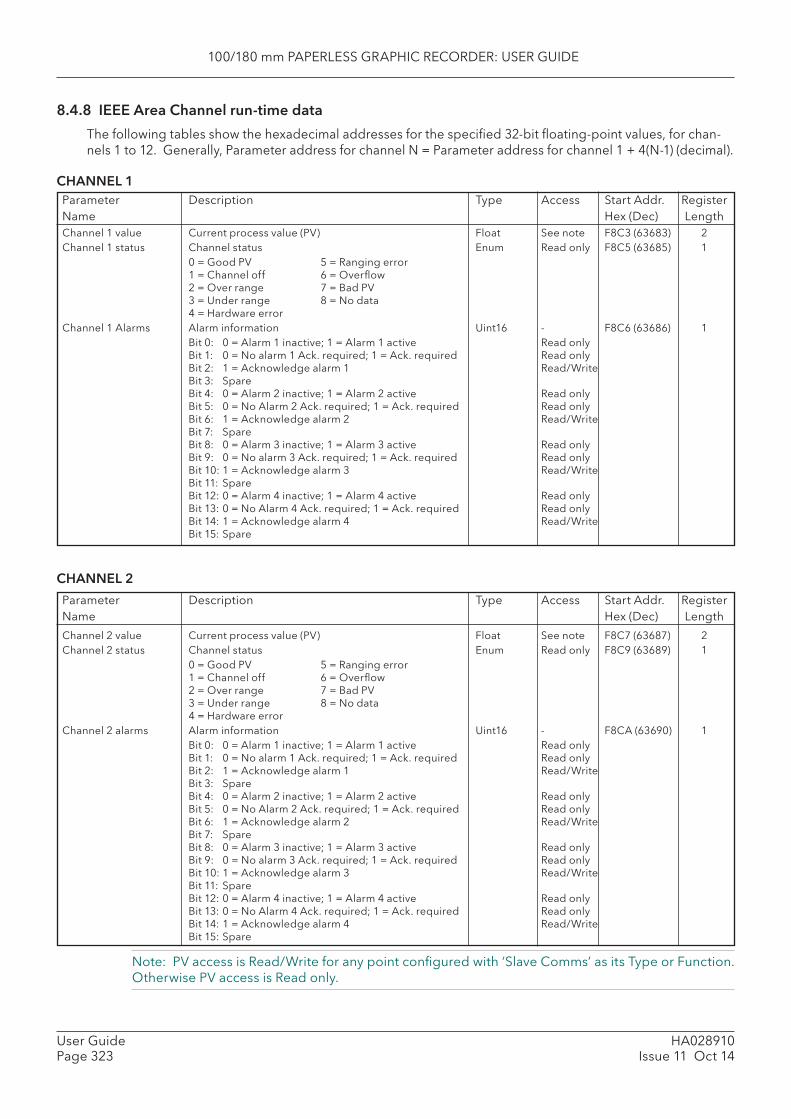
100/180 mm PAPERLESS GRAPHIC RECORDER: USER GUIDE
HA028910Issue 11 Oct 14
User GuidePage 323
Note: PV access is Read/Write for any point confi gured with ‘Slave Comms’ as its Type or Function. Otherwise PV access is Read only.
8.4.8 IEEE Area Channel run-time data
The following tables show the hexadecimal addresses for the specifi ed 32-bit fl oating-point values, for chan-nels 1 to 12. Generally, Parameter address for channel N = Parameter address for channel 1 + 4(N-1) (decimal).
CHANNEL 1Parameter Description Type Access Start Addr. RegisterName Hex (Dec) LengthChannel 1 value Current process value (PV) Float See note F8C3 (63683) 2Channel 1 status Channel status Enum Read only F8C5 (63685) 1 0 = Good PV 5 = Ranging error
1 = Channel off 6 = Overfl ow2 = Over range 7 = Bad PV3 = Under range 8 = No data4 = Hardware error
Channel 1 Alarms Alarm information Uint16 - F8C6 (63686) 1 Bit 0: 0 = Alarm 1 inactive; 1 = Alarm 1 active Read only
Bit 1: 0 = No alarm 1 Ack. required; 1 = Ack. required Read onlyBit 2: 1 = Acknowledge alarm 1 Read/WriteBit 3: SpareBit 4: 0 = Alarm 2 inactive; 1 = Alarm 2 active Read onlyBit 5: 0 = No Alarm 2 Ack. required; 1 = Ack. required Read onlyBit 6: 1 = Acknowledge alarm 2 Read/WriteBit 7: SpareBit 8: 0 = Alarm 3 inactive; 1 = Alarm 3 active Read onlyBit 9: 0 = No alarm 3 Ack. required; 1 = Ack. required Read onlyBit 10: 1 = Acknowledge alarm 3 Read/WriteBit 11: SpareBit 12: 0 = Alarm 4 inactive; 1 = Alarm 4 active Read onlyBit 13: 0 = No Alarm 4 Ack. required; 1 = Ack. required Read onlyBit 14: 1 = Acknowledge alarm 4 Read/WriteBit 15: Spare
Parameter Description Type Access Start Addr. RegisterName Hex (Dec) Length
Channel 2 value Current process value (PV) Float See note F8C7 (63687) 2Channel 2 status Channel status Enum Read only F8C9 (63689) 1 0 = Good PV 5 = Ranging error
1 = Channel off 6 = Overfl ow2 = Over range 7 = Bad PV3 = Under range 8 = No data4 = Hardware error
Channel 2 alarms Alarm information Uint16 - F8CA (63690) 1 Bit 0: 0 = Alarm 1 inactive; 1 = Alarm 1 active Read only
Bit 1: 0 = No alarm 1 Ack. required; 1 = Ack. required Read onlyBit 2: 1 = Acknowledge alarm 1 Read/WriteBit 3: SpareBit 4: 0 = Alarm 2 inactive; 1 = Alarm 2 active Read onlyBit 5: 0 = No Alarm 2 Ack. required; 1 = Ack. required Read onlyBit 6: 1 = Acknowledge alarm 2 Read/WriteBit 7: SpareBit 8: 0 = Alarm 3 inactive; 1 = Alarm 3 active Read onlyBit 9: 0 = No alarm 3 Ack. required; 1 = Ack. required Read onlyBit 10: 1 = Acknowledge alarm 3 Read/WriteBit 11: SpareBit 12: 0 = Alarm 4 inactive; 1 = Alarm 4 active Read onlyBit 13: 0 = No Alarm 4 Ack. required; 1 = Ack. required Read onlyBit 14: 1 = Acknowledge alarm 4 Read/WriteBit 15: Spare
CHANNEL 2
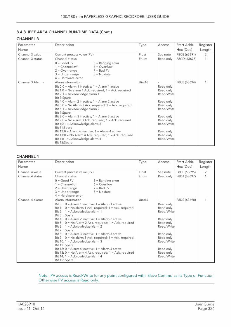
100/180 mm PAPERLESS GRAPHIC RECORDER: USER GUIDE
HA028910Issue 11 Oct 14
User GuidePage 324
Note: PV access is Read/Write for any point confi gured with ‘Slave Comms’ as its Type or Function. Otherwise PV access is Read only.
8.4.8 IEEE AREA CHANNEL RUN-TIME DATA (Cont.)
CHANNEL 3Parameter Description Type Access Start Addr. RegisterName Hex (Dec) Length
Parameter Description Type Access Start Addr. RegisterName Hex (Dec) Length
Channel 3 value Current process value (PV) Float See note F8CB (63691) 2Channel 3 status Channel status Enum Read only F8CD (63693) 1 0 = Good PV 5 = Ranging error
1 = Channel off 6 = Overfl ow2 = Over range 7 = Bad PV3 = Under range 8 = No data4 = Hardware error
Channel 3 Alarms Alarm information Uint16 - F8CE (63694) 1 Bit 0: 0 = Alarm 1 inactive; 1 = Alarm 1 active Read only
Bit 1: 0 = No alarm 1 Ack. required; 1 = Ack. required Read onlyBit 2: 1 = Acknowledge alarm 1 Read/WriteBit 3: SpareBit 4: 0 = Alarm 2 inactive; 1 = Alarm 2 active Read onlyBit 5: 0 = No Alarm 2 Ack. required; 1 = Ack. required Read onlyBit 6: 1 = Acknowledge alarm 2 Read/WriteBit 7: SpareBit 8: 0 = Alarm 3 inactive; 1 = Alarm 3 active Read onlyBit 9: 0 = No alarm 3 Ack. required; 1 = Ack. required Read onlyBit 10: 1 = Acknowledge alarm 3 Read/WriteBit 11: SpareBit 12: 0 = Alarm 4 inactive; 1 = Alarm 4 active Read onlyBit 13: 0 = No Alarm 4 Ack. required; 1 = Ack. required Read onlyBit 14: 1 = Acknowledge alarm 4 Read/WriteBit 15: Spare
CHANNEL 4
Channel 4 value Current process value (PV) Float See note F8CF (63695) 2Channel 4 status Channel status Enum Read only F8D1 (63697) 1 0 = Good PV 5 = Ranging error
1 = Channel off 6 = Overfl ow2 = Over range 7 = Bad PV3 = Under range 8 = No data4 = Hardware error
Channel 4 alarms Alarm information Uint16 - F8D2 (63698) 1 Bit 0: 0 = Alarm 1 inactive; 1 = Alarm 1 active Read only
Bit 1: 0 = No alarm 1 Ack. required; 1 = Ack. required Read onlyBit 2: 1 = Acknowledge alarm 1 Read/WriteBit 3: SpareBit 4: 0 = Alarm 2 inactive; 1 = Alarm 2 active Read onlyBit 5: 0 = No Alarm 2 Ack. required; 1 = Ack. required Read onlyBit 6: 1 = Acknowledge alarm 2 Read/WriteBit 7: SpareBit 8: 0 = Alarm 3 inactive; 1 = Alarm 3 active Read onlyBit 9: 0 = No alarm 3 Ack. required; 1 = Ack. required Read onlyBit 10: 1 = Acknowledge alarm 3 Read/WriteBit 11: SpareBit 12: 0 = Alarm 4 inactive; 1 = Alarm 4 active Read onlyBit 13: 0 = No Alarm 4 Ack. required; 1 = Ack. required Read onlyBit 14: 1 = Acknowledge alarm 4 Read/WriteBit 15: Spare
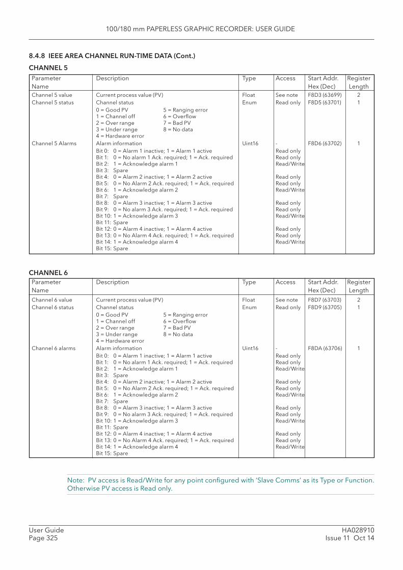
100/180 mm PAPERLESS GRAPHIC RECORDER: USER GUIDE
HA028910Issue 11 Oct 14
User GuidePage 325
Note: PV access is Read/Write for any point confi gured with ‘Slave Comms’ as its Type or Function. Otherwise PV access is Read only.
8.4.8 IEEE AREA CHANNEL RUN-TIME DATA (Cont.)
CHANNEL 5Parameter Description Type Access Start Addr. RegisterName Hex (Dec) Length
Parameter Description Type Access Start Addr. RegisterName Hex (Dec) Length
Channel 5 value Current process value (PV) Float See note F8D3 (63699) 2Channel 5 status Channel status Enum Read only F8D5 (63701) 1 0 = Good PV 5 = Ranging error
1 = Channel off 6 = Overfl ow2 = Over range 7 = Bad PV3 = Under range 8 = No data4 = Hardware error
Channel 5 Alarms Alarm information Uint16 - F8D6 (63702) 1 Bit 0: 0 = Alarm 1 inactive; 1 = Alarm 1 active Read only
Bit 1: 0 = No alarm 1 Ack. required; 1 = Ack. required Read onlyBit 2: 1 = Acknowledge alarm 1 Read/WriteBit 3: SpareBit 4: 0 = Alarm 2 inactive; 1 = Alarm 2 active Read onlyBit 5: 0 = No Alarm 2 Ack. required; 1 = Ack. required Read onlyBit 6: 1 = Acknowledge alarm 2 Read/WriteBit 7: SpareBit 8: 0 = Alarm 3 inactive; 1 = Alarm 3 active Read onlyBit 9: 0 = No alarm 3 Ack. required; 1 = Ack. required Read onlyBit 10: 1 = Acknowledge alarm 3 Read/WriteBit 11: SpareBit 12: 0 = Alarm 4 inactive; 1 = Alarm 4 active Read onlyBit 13: 0 = No Alarm 4 Ack. required; 1 = Ack. required Read onlyBit 14: 1 = Acknowledge alarm 4 Read/WriteBit 15: Spare
CHANNEL 6
Channel 6 value Current process value (PV) Float See note F8D7 (63703) 2Channel 6 status Channel status Enum Read only F8D9 (63705) 1 0 = Good PV 5 = Ranging error
1 = Channel off 6 = Overfl ow2 = Over range 7 = Bad PV3 = Under range 8 = No data4 = Hardware error
Channel 6 alarms Alarm information Uint16 - F8DA (63706) 1 Bit 0: 0 = Alarm 1 inactive; 1 = Alarm 1 active Read only
Bit 1: 0 = No alarm 1 Ack. required; 1 = Ack. required Read onlyBit 2: 1 = Acknowledge alarm 1 Read/WriteBit 3: SpareBit 4: 0 = Alarm 2 inactive; 1 = Alarm 2 active Read onlyBit 5: 0 = No Alarm 2 Ack. required; 1 = Ack. required Read onlyBit 6: 1 = Acknowledge alarm 2 Read/WriteBit 7: SpareBit 8: 0 = Alarm 3 inactive; 1 = Alarm 3 active Read onlyBit 9: 0 = No alarm 3 Ack. required; 1 = Ack. required Read onlyBit 10: 1 = Acknowledge alarm 3 Read/WriteBit 11: SpareBit 12: 0 = Alarm 4 inactive; 1 = Alarm 4 active Read onlyBit 13: 0 = No Alarm 4 Ack. required; 1 = Ack. required Read onlyBit 14: 1 = Acknowledge alarm 4 Read/WriteBit 15: Spare
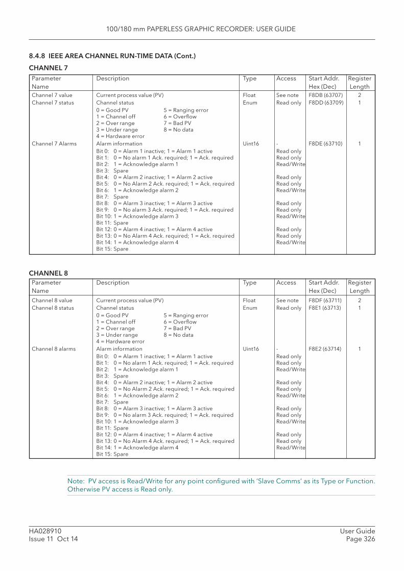
100/180 mm PAPERLESS GRAPHIC RECORDER: USER GUIDE
HA028910Issue 11 Oct 14
User GuidePage 326
Note: PV access is Read/Write for any point confi gured with ‘Slave Comms’ as its Type or Function. Otherwise PV access is Read only.
8.4.8 IEEE AREA CHANNEL RUN-TIME DATA (Cont.)
CHANNEL 7Parameter Description Type Access Start Addr. RegisterName Hex (Dec) Length
Parameter Description Type Access Start Addr. RegisterName Hex (Dec) Length
Channel 7 value Current process value (PV) Float See note F8DB (63707) 2Channel 7 status Channel status Enum Read only F8DD (63709) 1 0 = Good PV 5 = Ranging error
1 = Channel off 6 = Overfl ow2 = Over range 7 = Bad PV3 = Under range 8 = No data4 = Hardware error
Channel 7 Alarms Alarm information Uint16 - F8DE (63710) 1 Bit 0: 0 = Alarm 1 inactive; 1 = Alarm 1 active Read only
Bit 1: 0 = No alarm 1 Ack. required; 1 = Ack. required Read onlyBit 2: 1 = Acknowledge alarm 1 Read/WriteBit 3: SpareBit 4: 0 = Alarm 2 inactive; 1 = Alarm 2 active Read onlyBit 5: 0 = No Alarm 2 Ack. required; 1 = Ack. required Read onlyBit 6: 1 = Acknowledge alarm 2 Read/WriteBit 7: SpareBit 8: 0 = Alarm 3 inactive; 1 = Alarm 3 active Read onlyBit 9: 0 = No alarm 3 Ack. required; 1 = Ack. required Read onlyBit 10: 1 = Acknowledge alarm 3 Read/WriteBit 11: SpareBit 12: 0 = Alarm 4 inactive; 1 = Alarm 4 active Read onlyBit 13: 0 = No Alarm 4 Ack. required; 1 = Ack. required Read onlyBit 14: 1 = Acknowledge alarm 4 Read/WriteBit 15: Spare
CHANNEL 8
Channel 8 value Current process value (PV) Float See note F8DF (63711) 2Channel 8 status Channel status Enum Read only F8E1 (63713) 1 0 = Good PV 5 = Ranging error
1 = Channel off 6 = Overfl ow2 = Over range 7 = Bad PV3 = Under range 8 = No data4 = Hardware error
Channel 8 alarms Alarm information Uint16 - F8E2 (63714) 1 Bit 0: 0 = Alarm 1 inactive; 1 = Alarm 1 active Read only
Bit 1: 0 = No alarm 1 Ack. required; 1 = Ack. required Read onlyBit 2: 1 = Acknowledge alarm 1 Read/WriteBit 3: SpareBit 4: 0 = Alarm 2 inactive; 1 = Alarm 2 active Read onlyBit 5: 0 = No Alarm 2 Ack. required; 1 = Ack. required Read onlyBit 6: 1 = Acknowledge alarm 2 Read/WriteBit 7: SpareBit 8: 0 = Alarm 3 inactive; 1 = Alarm 3 active Read onlyBit 9: 0 = No alarm 3 Ack. required; 1 = Ack. required Read onlyBit 10: 1 = Acknowledge alarm 3 Read/WriteBit 11: SpareBit 12: 0 = Alarm 4 inactive; 1 = Alarm 4 active Read onlyBit 13: 0 = No Alarm 4 Ack. required; 1 = Ack. required Read onlyBit 14: 1 = Acknowledge alarm 4 Read/WriteBit 15: Spare
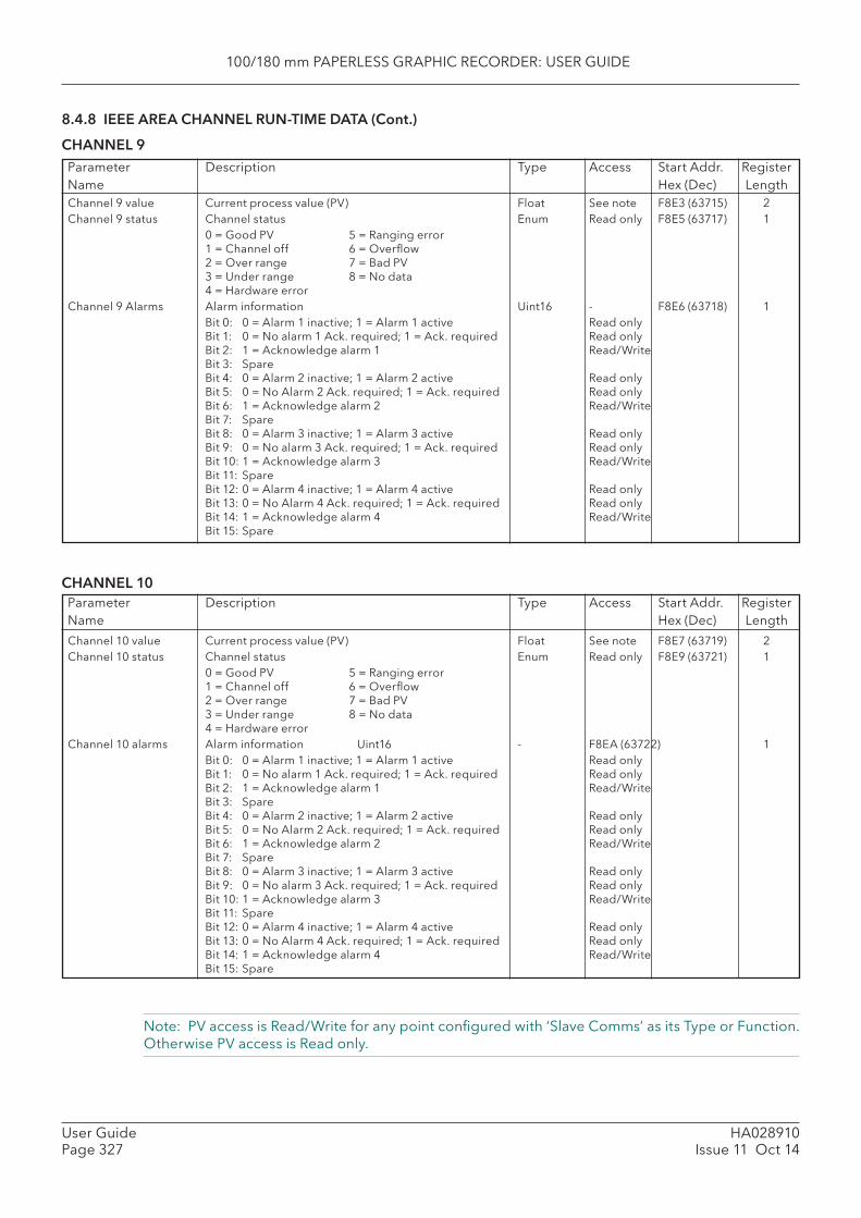
100/180 mm PAPERLESS GRAPHIC RECORDER: USER GUIDE
HA028910Issue 11 Oct 14
User GuidePage 327
Note: PV access is Read/Write for any point confi gured with ‘Slave Comms’ as its Type or Function. Otherwise PV access is Read only.
8.4.8 IEEE AREA CHANNEL RUN-TIME DATA (Cont.)
CHANNEL 9Parameter Description Type Access Start Addr. RegisterName Hex (Dec) Length
Parameter Description Type Access Start Addr. RegisterName Hex (Dec) Length
Channel 9 value Current process value (PV) Float See note F8E3 (63715) 2Channel 9 status Channel status Enum Read only F8E5 (63717) 1 0 = Good PV 5 = Ranging error
1 = Channel off 6 = Overfl ow2 = Over range 7 = Bad PV3 = Under range 8 = No data4 = Hardware error
Channel 9 Alarms Alarm information Uint16 - F8E6 (63718) 1 Bit 0: 0 = Alarm 1 inactive; 1 = Alarm 1 active Read only
Bit 1: 0 = No alarm 1 Ack. required; 1 = Ack. required Read onlyBit 2: 1 = Acknowledge alarm 1 Read/WriteBit 3: SpareBit 4: 0 = Alarm 2 inactive; 1 = Alarm 2 active Read onlyBit 5: 0 = No Alarm 2 Ack. required; 1 = Ack. required Read onlyBit 6: 1 = Acknowledge alarm 2 Read/WriteBit 7: SpareBit 8: 0 = Alarm 3 inactive; 1 = Alarm 3 active Read onlyBit 9: 0 = No alarm 3 Ack. required; 1 = Ack. required Read onlyBit 10: 1 = Acknowledge alarm 3 Read/WriteBit 11: SpareBit 12: 0 = Alarm 4 inactive; 1 = Alarm 4 active Read onlyBit 13: 0 = No Alarm 4 Ack. required; 1 = Ack. required Read onlyBit 14: 1 = Acknowledge alarm 4 Read/WriteBit 15: Spare
CHANNEL 10
Channel 10 value Current process value (PV) Float See note F8E7 (63719) 2Channel 10 status Channel status Enum Read only F8E9 (63721) 1 0 = Good PV 5 = Ranging error
1 = Channel off 6 = Overfl ow2 = Over range 7 = Bad PV3 = Under range 8 = No data4 = Hardware error
Channel 10 alarms Alarm information Uint16 - F8EA (63722) 1 Bit 0: 0 = Alarm 1 inactive; 1 = Alarm 1 active Read only
Bit 1: 0 = No alarm 1 Ack. required; 1 = Ack. required Read onlyBit 2: 1 = Acknowledge alarm 1 Read/WriteBit 3: SpareBit 4: 0 = Alarm 2 inactive; 1 = Alarm 2 active Read onlyBit 5: 0 = No Alarm 2 Ack. required; 1 = Ack. required Read onlyBit 6: 1 = Acknowledge alarm 2 Read/WriteBit 7: SpareBit 8: 0 = Alarm 3 inactive; 1 = Alarm 3 active Read onlyBit 9: 0 = No alarm 3 Ack. required; 1 = Ack. required Read onlyBit 10: 1 = Acknowledge alarm 3 Read/WriteBit 11: SpareBit 12: 0 = Alarm 4 inactive; 1 = Alarm 4 active Read onlyBit 13: 0 = No Alarm 4 Ack. required; 1 = Ack. required Read onlyBit 14: 1 = Acknowledge alarm 4 Read/WriteBit 15: Spare
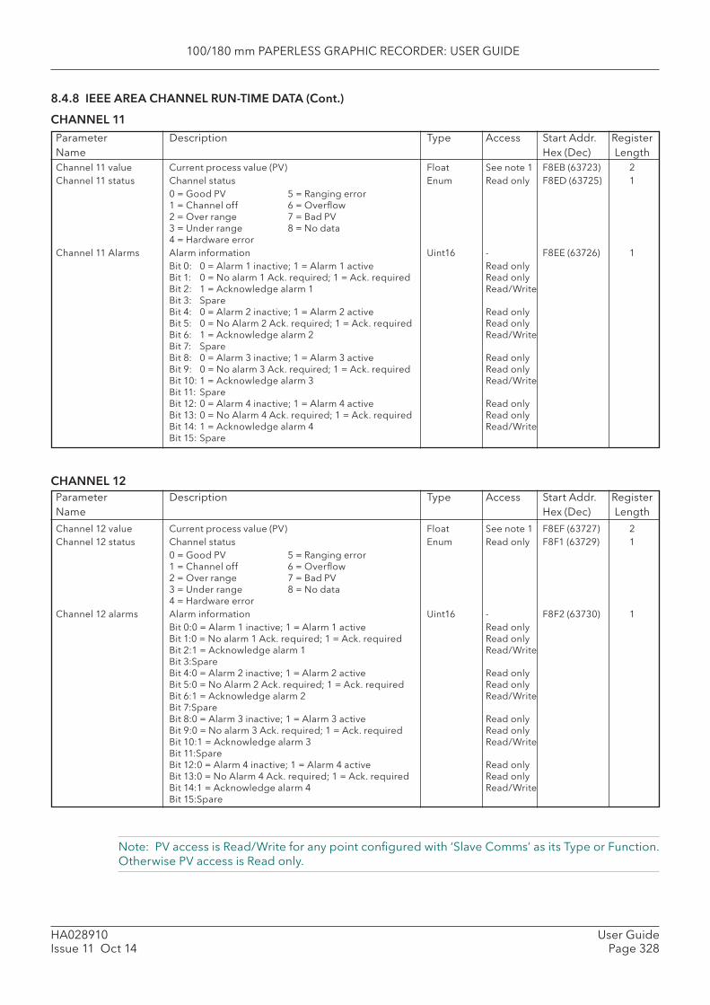
100/180 mm PAPERLESS GRAPHIC RECORDER: USER GUIDE
HA028910Issue 11 Oct 14
User GuidePage 328
Note: PV access is Read/Write for any point confi gured with ‘Slave Comms’ as its Type or Function. Otherwise PV access is Read only.
8.4.8 IEEE AREA CHANNEL RUN-TIME DATA (Cont.)
CHANNEL 11Parameter Description Type Access Start Addr. RegisterName Hex (Dec) Length
Parameter Description Type Access Start Addr. RegisterName Hex (Dec) Length
Channel 11 value Current process value (PV) Float See note 1 F8EB (63723) 2Channel 11 status Channel status Enum Read only F8ED (63725) 1 0 = Good PV 5 = Ranging error
1 = Channel off 6 = Overfl ow2 = Over range 7 = Bad PV3 = Under range 8 = No data4 = Hardware error
Channel 11 Alarms Alarm information Uint16 - F8EE (63726) 1 Bit 0: 0 = Alarm 1 inactive; 1 = Alarm 1 active Read only
Bit 1: 0 = No alarm 1 Ack. required; 1 = Ack. required Read onlyBit 2: 1 = Acknowledge alarm 1 Read/WriteBit 3: SpareBit 4: 0 = Alarm 2 inactive; 1 = Alarm 2 active Read onlyBit 5: 0 = No Alarm 2 Ack. required; 1 = Ack. required Read onlyBit 6: 1 = Acknowledge alarm 2 Read/WriteBit 7: SpareBit 8: 0 = Alarm 3 inactive; 1 = Alarm 3 active Read onlyBit 9: 0 = No alarm 3 Ack. required; 1 = Ack. required Read onlyBit 10: 1 = Acknowledge alarm 3 Read/WriteBit 11: SpareBit 12: 0 = Alarm 4 inactive; 1 = Alarm 4 active Read onlyBit 13: 0 = No Alarm 4 Ack. required; 1 = Ack. required Read onlyBit 14: 1 = Acknowledge alarm 4 Read/WriteBit 15: Spare
CHANNEL 12
Channel 12 value Current process value (PV) Float See note 1 F8EF (63727) 2Channel 12 status Channel status Enum Read only F8F1 (63729) 1 0 = Good PV 5 = Ranging error
1 = Channel off 6 = Overfl ow2 = Over range 7 = Bad PV3 = Under range 8 = No data4 = Hardware error
Channel 12 alarms Alarm information Uint16 - F8F2 (63730) 1 Bit 0: 0 = Alarm 1 inactive; 1 = Alarm 1 active Read only
Bit 1: 0 = No alarm 1 Ack. required; 1 = Ack. required Read onlyBit 2: 1 = Acknowledge alarm 1 Read/WriteBit 3: SpareBit 4: 0 = Alarm 2 inactive; 1 = Alarm 2 active Read onlyBit 5: 0 = No Alarm 2 Ack. required; 1 = Ack. required Read onlyBit 6: 1 = Acknowledge alarm 2 Read/WriteBit 7: SpareBit 8: 0 = Alarm 3 inactive; 1 = Alarm 3 active Read onlyBit 9: 0 = No alarm 3 Ack. required; 1 = Ack. required Read onlyBit 10: 1 = Acknowledge alarm 3 Read/WriteBit 11: SpareBit 12: 0 = Alarm 4 inactive; 1 = Alarm 4 active Read onlyBit 13: 0 = No Alarm 4 Ack. required; 1 = Ack. required Read onlyBit 14: 1 = Acknowledge alarm 4 Read/WriteBit 15: Spare
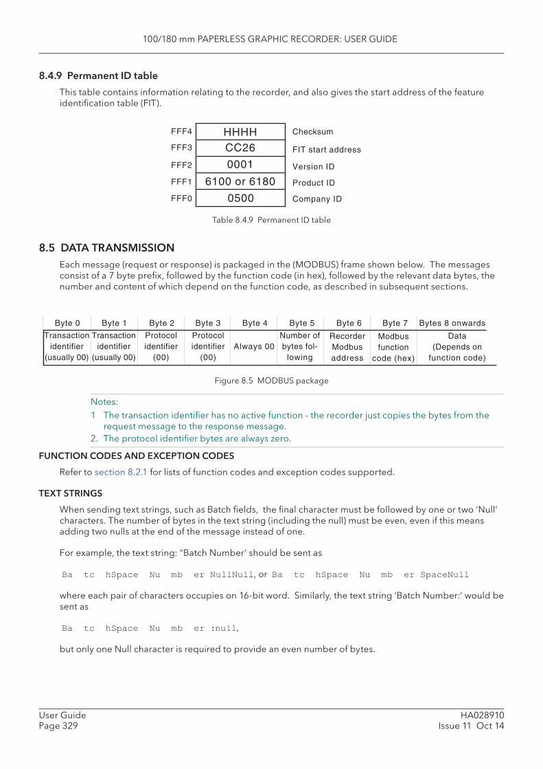
100/180 mm PAPERLESS GRAPHIC RECORDER: USER GUIDE
HA028910Issue 11 Oct 14
User GuidePage 329
FFF0 0500
FFF1
FFF2
FFF3
FFF4
6100 or 6180
0001
CC26HHHH
Product ID
Version ID
FIT start address
Checksum
Company ID
Byte 0
Transactionidentifier
(usually 00)
Transactionidentifier
(usually 00)
Protocolidentifier
(00)
Protocolidentifier
(00)
Byte 1 Byte 2 Byte 3 Byte 4
Number ofbytes fol-
lowing
Byte 5
Always 00
Byte 6
RecorderModbusaddress
Byte 7
Modbusfunction
code (hex)
Bytes 8 onwards
Data(Depends on
function code)
8.4.9 Permanent ID table
This table contains information relating to the recorder, and also gives the start address of the feature identifi cation table (FIT).
Table 8.4.9 Permanent ID table
8.5 DATA TRANSMISSIONEach message (request or response) is packaged in the (MODBUS) frame shown below. The messages consist of a 7 byte prefi x, followed by the function code (in hex), followed by the relevant data bytes, the number and content of which depend on the function code, as described in subsequent sections.
Figure 8.5 MODBUS package
Notes:1 The transaction identifi er has no active function - the recorder just copies the bytes from the
request message to the response message.2. The protocol identifi er bytes are always zero.
FUNCTION CODES AND EXCEPTION CODES
Refer to section 8.2.1 for lists of function codes and exception codes supported.
TEXT STRINGS
When sending text strings, such as Batch fi elds, the fi nal character must be followed by one or two ‘Null’ characters. The number of bytes in the text string (including the null) must be even, even if this means adding two nulls at the end of the message instead of one.
For example, the text string: “Batch Number’ should be sent as
Ba tc hSpace Nu mb er NullNull, or Ba tc hSpace Nu mb er SpaceNull
where each pair of characters occupies on 16-bit word. Similarly, the text string ‘Batch Number:’ would be sent as
Ba tc hSpace Nu mb er :null,
but only one Null character is required to provide an even number of bytes.
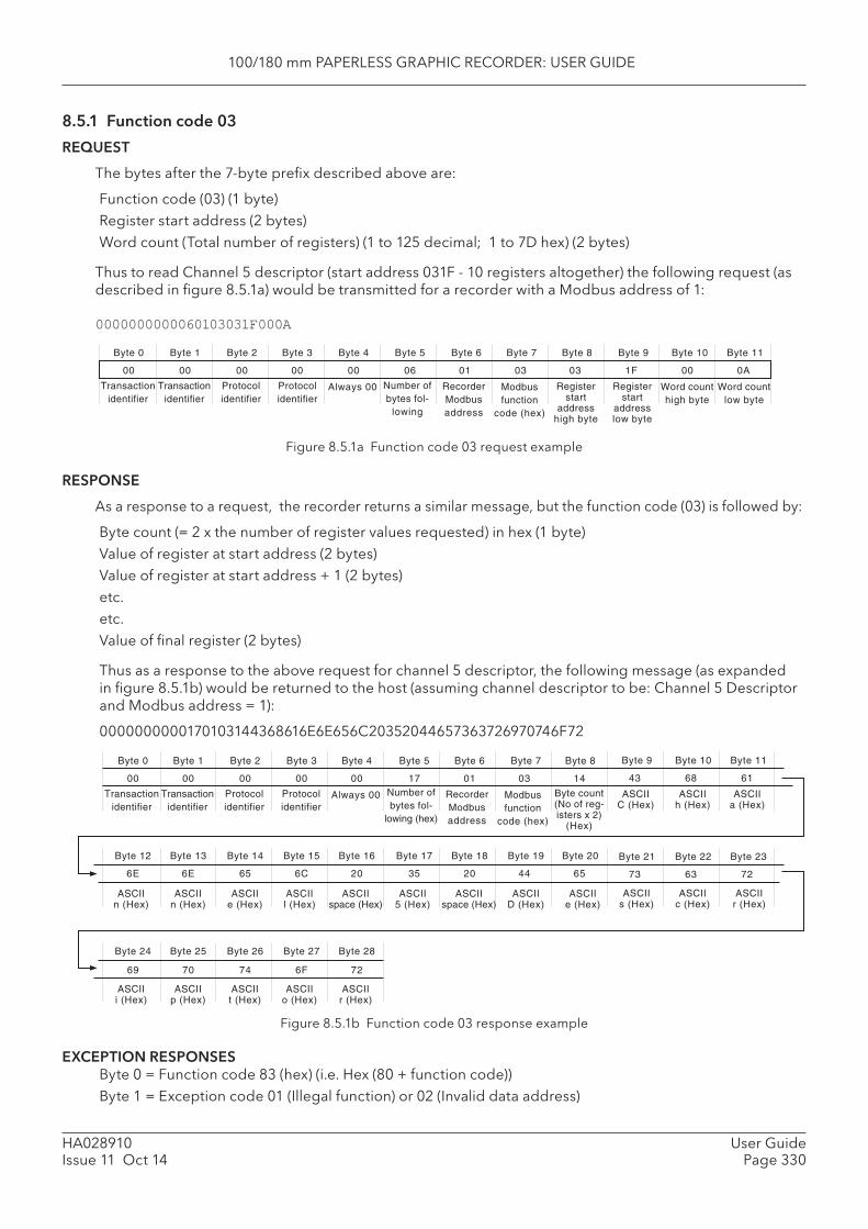
100/180 mm PAPERLESS GRAPHIC RECORDER: USER GUIDE
HA028910Issue 11 Oct 14
User GuidePage 330
Byte 0
Transactionidentifier
Transactionidentifier
Protocolidentifier
Protocolidentifier
Byte 1 Byte 2 Byte 3 Byte 4
Number ofbytes fol-
lowing
Byte 5
Always 00
Byte 6
RecorderModbusaddress
Byte 7
Modbusfunction
code (hex)
00 00 00 00 00 06 01 03
Byte 8 Byte 9
Registerstart
addresshigh byte
Byte 10
Word counthigh byte
Byte 11
Registerstart
addresslow byte
Word countlow byte
03 1F 00 0A
Byte 0
Transactionidentifier
Transactionidentifier
Protocolidentifier
Protocolidentifier
Byte 1 Byte 2 Byte 3 Byte 4
Number ofbytes fol-
lowing (hex)
Byte 5
Always 00
Byte 6
RecorderModbusaddress
Byte 7
Modbusfunction
code (hex)
00 00 00 00 00 17 01 03
Byte 8
Byte count(No of reg-isters x 2)
(Hex)
14
Byte 9 Byte 10 Byte 11
ASCIIC (Hex)
43 68 61
ASCIIh (Hex)
ASCIIa (Hex)
Byte 12 Byte 13 Byte 14 Byte 15 Byte 16 Byte 17 Byte 18 Byte 19
6E 6E 65 6C 20 35 20 44
Byte 20
65
ASCIIn (Hex)
ASCIIn (Hex)
ASCIIe (Hex)
ASCIIl (Hex)
ASCIIspace (Hex)
ASCII5 (Hex)
ASCIIspace (Hex)
ASCIID (Hex)
ASCIIe (Hex)
Byte 24 Byte 25 Byte 26 Byte 27 Byte 28
Byte 21 Byte 22 Byte 23
73 63 72
ASCIIs (Hex)
ASCIIc (Hex)
ASCIIr (Hex)
69 70 74 6F 72
ASCIIi (Hex)
ASCIIp (Hex)
ASCIIt (Hex)
ASCIIo (Hex)
ASCIIr (Hex)
8.5.1 Function code 03
REQUEST
The bytes after the 7-byte prefi x described above are:
Function code (03) (1 byte)Register start address (2 bytes)Word count (Total number of registers) (1 to 125 decimal; 1 to 7D hex) (2 bytes)
Thus to read Channel 5 descriptor (start address 031F - 10 registers altogether) the following request (as described in fi gure 8.5.1a) would be transmitted for a recorder with a Modbus address of 1:
0000000000060103031F000A
Figure 8.5.1a Function code 03 request example
RESPONSE
As a response to a request, the recorder returns a similar message, but the function code (03) is followed by:
Byte count (= 2 x the number of register values requested) in hex (1 byte)Value of register at start address (2 bytes)Value of register at start address + 1 (2 bytes)etc.etc.Value of fi nal register (2 bytes)
Thus as a response to the above request for channel 5 descriptor, the following message (as expanded in fi gure 8.5.1b) would be returned to the host (assuming channel descriptor to be: Channel 5 Descriptor and Modbus address = 1):
0000000000170103144368616E6E656C20352044657363726970746F72
Figure 8.5.1b Function code 03 response example
EXCEPTION RESPONSESByte 0 = Function code 83 (hex) (i.e. Hex (80 + function code))Byte 1 = Exception code 01 (Illegal function) or 02 (Invalid data address)
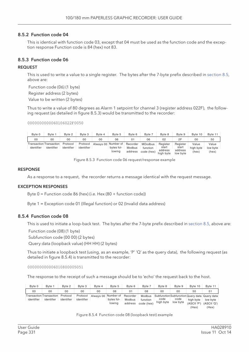
100/180 mm PAPERLESS GRAPHIC RECORDER: USER GUIDE
HA028910Issue 11 Oct 14
User GuidePage 331
Byte 0
Transactionidentifier
Transactionidentifier
Protocolidentifier
Protocolidentifier
Byte 1 Byte 2 Byte 3 Byte 4
Number ofbytes fol-
lowing
Byte 5
Always 00
Byte 6
RecorderModbusaddress
Byte 7
MOodbusfunction
code (hex)
00 00 00 00 00 06 01 06
Byte 8 Byte 9
Registerstart
addresshigh byte
Byte 10
Valuehigh byte
(hex)
Byte 11
Registerstart
addresslow byte
Valuelow byte
(hex)
02 2F 00 50
Byte 0
Transactionidentifier
Transactionidentifier
Protocolidentifier
Protocolidentifier
Byte 1 Byte 2 Byte 3 Byte 4
Number ofbytes fol-
lowing
Byte 5
Always 00
Byte 6
RecorderModbusaddress
Byte 7
Modbusfunction
code (hex)
00 00 00 00 00 06 01 08
Byte 8 Byte 9
Subfunctioncode
high byte
Byte 10
Query datahigh byte
(ASCII 'P')(Hex)
Byte 11
Subfunctioncode
low byte
Query datalow byte
(ASCII 'Q')(Hex)
00 00 50 51
8.5.2 Function code 04
This is identical with function code 03, except that 04 must be used as the function code and the excep-tion response Function code is 84 (hex) not 83.
8.5.3 Function code 06
REQUEST
This is used to write a value to a single register. The bytes after the 7-byte prefi x described in section 8.5, above are:
Function code (06) (1 byte)Register address (2 bytes)Value to be written (2 bytes)
Thus to write a value of 80 degrees as Alarm 1 setpoint for channel 3 (register address 022F), the follow-ing request (as detailed in fi gure 8.5.3) would be transmitted to the recorder:
0000000000060106022F0050
Figure 8.5.3 Function code 06 request/response example
RESPONSE
As a response to a request, the recorder returns a message identical with the request message.
EXCEPTION RESPONSES
Byte 0 = Function code 86 (hex) (i.e. Hex (80 + function code))
Byte 1 = Exception code 01 (Illegal function) or 02 (Invalid data address)
8.5.4 Function code 08
This is used to initiate a loop-back test. The bytes after the 7-byte prefi x described in section 8.5, above are:
Function code (08) (1 byte)Subfunction code (00 00) (2 bytes)Query data (loopback value) (HH HH) (2 bytes)
Thus to initiate a loopback test (using, as an example, ‘P’ ’Q’ as the query data), the following request (as detailed in fi gure 8.5.4) is transmitted to the recorder:
000000000006010800005051
The response to the receipt of such a message should be to ‘echo’ the request back to the host.
Figure 8.5.4 Function code 08 (loopback test) example
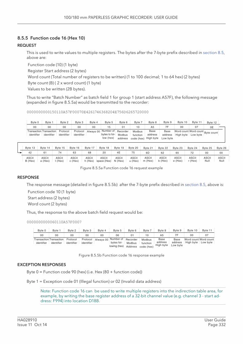
100/180 mm PAPERLESS GRAPHIC RECORDER: USER GUIDE
HA028910Issue 11 Oct 14
User GuidePage 332
Byte 0
Transactionidentifier
Transactionidentifier
Protocolidentifier
Protocolidentifier
Byte 1 Byte 2 Byte 3 Byte 4 Byte 5
Always 00
Byte 6
RecorderModbusaddress
Byte 7
00 00 00 00 00 15 01 10
Byte 8
Baseaddress
High byte
A5
Byte 9 Byte 10 Byte 11
Baseaddress
Low byte
7F 00 07
Word countHigh byte
Byte 12
0E
Byte countWord countLow byte
Number ofbytes to fol-low (hex)
Modbusfunction
code (hex)
Byte 13 Byte 14 Byte 15 Byte 16 Byte 17 Byte 18 Byte 19
42 61 74 63 68 20 4E
Byte 20
75
ASCIIB (Hex)
ASCIIa (Hex)
ASCIIt (Hex)
ASCIIc (Hex)
ASCIIh (Hex)
ASCIIspace (Hex)
ASCIIN (Hex)
ASCIIu (Hex)
Byte 21 Byte 22 Byte 23
6D 62 65
ASCIIm (Hex)
ASCIIb (Hex)
ASCIIe (Hex)
Byte 24
72
ASCIIr (Hex)
Byte 25
00
ASCIINull
Byte 26
00
ASCIINull
Byte 0
Transactionidentifier
Transactionidentifier
Protocolidentifier
Protocolidentifier
Byte 1 Byte 2 Byte 3 Byte 4
Number ofbytes fol-
lowing (hex)
Byte 5
Always 00
Byte 6
RecorderModbusAddress
Byte 7
Modbusfunction
code (hex)
00 00 00 00 00 06 01 10
Byte 8
Baseaddress
High byte
A5
Byte 9 Byte 10 Byte 11
Baseaddress
Low byte
7F 00 07
Word countHigh byte
Word countLow byte
8.5.5 Function code 16 (Hex 10)
REQUEST
This is used to write values to multiple registers. The bytes after the 7-byte prefi x described in section 8.5, above are:
Function code (10) (1 byte)Register Start address (2 bytes)Word count (Total number of registers to be written) (1 to 100 decimal; 1 to 64 hex) (2 bytes)Byte count (B) ( 2 x word count) (1 byte)Values to be written (2B bytes).
Thus to write ”Batch Number” as batch fi eld 1 for group 1 (start address A57F), the following message (expanded in fi gure 8.5.5a) would be transmitted to the recorder:
0000000000150110A57F00070E4261746368204E756D6265720000
Figure 8.5.5a Function code 16 request example
RESPONSE
The response message (detailed in fi gure 8.5.5b) after the 7-byte prefi x described in section 8.5, above is:
Function code 10 (1 byte)Start address (2 bytes)Word count (2 bytes)
Thus, the response to the above batch fi eld request would be:
0000000000060110A57F0007
Figure 8.5.5b Function code 16 response example
EXCEPTION RESPONSES
Byte 0 = Function code 90 (hex) (i.e. Hex (80 + function code))
Byte 1 = Exception code 01 (Illegal function) or 02 (Invalid data address)
Note: Function code 16 can be used to write multiple registers into the indirection table area, for example, by writing the base register address of a 32-bit channel value (e.g. channel 3 - start ad-dress: F994) into location D18B.
100/180 mm PAPERLESS GRAPHIC RECORDER: USER GUIDE
HA028910Issue 11 Oct 14
User GuidePage 333
9 ANALOGUE OUTPUT OPTION Up to four analogue output boards can be fi tted, each of which supplies two outputs. This allows any of the recorder points to be output as a voltage or current signal, as confi gured. Any part of the source point’s span can be mapped to the output range, and the outputs can be adjusted (as described below) to compensate for errors in the monitoring system.
9.1 SIGNAL WIRINGFigure 2.2.1d shows the output wiring for analogue output boards.
9.2 SPECIFICATIONSee Annex A for the analogue output board specifi cation.
9.3 CONFIGURATIONSee section 4.3.17 (output channel confi guration) for details.
9.4 OUTPUT ADJUSTNotes1. Output adjust is relevant only to output channels confi gured as ‘V’ or ‘mA’, not to those confi g-
ured as Master Comms.2. Output channels can be adjusted only by users with ‘Adjust I/O’ access permission (section
4.4.1)
9.4.1 Adjustment procedure
This procedure is carried out as follows:
1. Select ‘Output Adjust’ in the System menu.2. Select the required channel. 3. Enter a low value for the recorder to output.4. Observe what value the monitoring equipment is reading for this output5. Enter this monitored value.6. Repeat for a high value.
Note: 10% and 90% of output range are commonly used as low and high values respectively.
Figure 9.4.1 below, shows typical adjust pages.
9.4.2 Adjustment removal
Adjustments can be removed at any time, as follows:
1. Select ‘Output Adjust’ in the System menu.2. Select the required channel. 3. Operate the ‘Remove Adjust’ key4. Select ‘Yes’ from the resulting confi rmation dialogue.
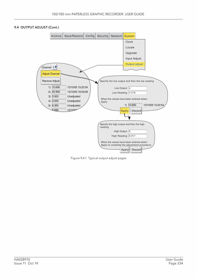
100/180 mm PAPERLESS GRAPHIC RECORDER: USER GUIDE
HA028910Issue 11 Oct 14
User GuidePage 334
9.4 OUTPUT ADJUST (Cont.)
Figure 9.4.1 Typical output adjust pages
Specify the low output and then the low reading
Low Output
Low Reading
4
4.018
When the values have been entered selectApply
1) 10.690 13/10/05 15:22:54
Apply Discard
Channel
Adjust Channel
Remove Adjust
4
1)
2)
3)
4)
5)
6)
10.690
20.960
3.563
0.000
9.365
8.896
13/10/05 15:22:54
13/10/05 16:03:09
Unadjusted
Unadjusted
Unadjusted
12/10/05 14:29:26
Specify the high output and then the highreading
High Output
High Reading
9
8.917
When the values have been entered selectApply to complete the adjustment procedure.
Apply Discard
Archive SystemSave/Restore Config Security Network
Clock
Locale
Upgrade
Input Adjust
Output adjust
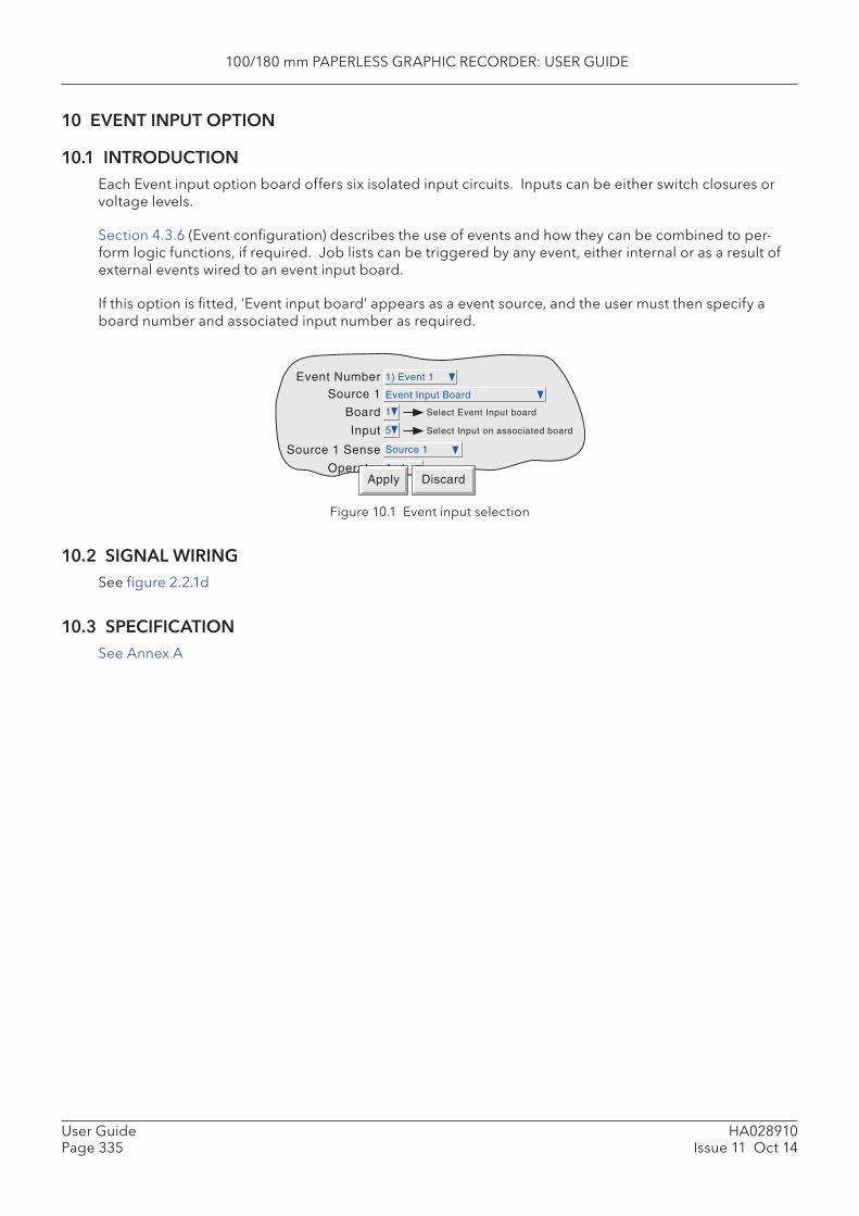
100/180 mm PAPERLESS GRAPHIC RECORDER: USER GUIDE
HA028910Issue 11 Oct 14
User GuidePage 335
10 EVENT INPUT OPTION
10.1 INTRODUCTIONEach Event input option board offers six isolated input circuits. Inputs can be either switch closures or voltage levels.
Section 4.3.6 (Event confi guration) describes the use of events and how they can be combined to per-form logic functions, if required. Job lists can be triggered by any event, either internal or as a result of external events wired to an event input board.
If this option is fi tted, ‘Event input board’ appears as a event source, and the user must then specify a board number and associated input number as required.
Figure 10.1 Event input selection
10.2 SIGNAL WIRINGSee fi gure 2.2.1d
10.3 SPECIFICATIONSee Annex A
Event Number 1) Event 1
Source 1 Event Input Board
Board 1
Source 1 Sense Source 1
Operator
Select Event Input board
Input 5
And
Select Input on associated board
Apply Discard
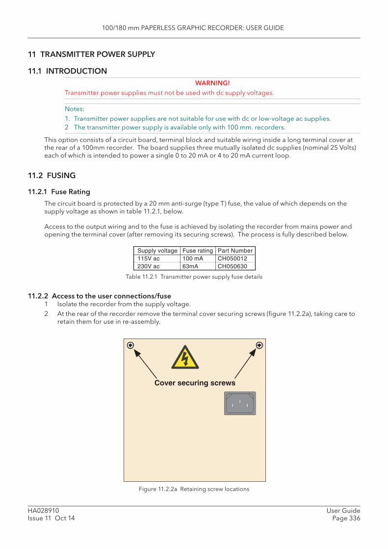
100/180 mm PAPERLESS GRAPHIC RECORDER: USER GUIDE
HA028910Issue 11 Oct 14
User GuidePage 336
11 TRANSMITTER POWER SUPPLY
11.1 INTRODUCTION WARNING!
Transmitter power supplies must not be used with dc supply voltages.
Notes:1. Transmitter power supplies are not suitable for use with dc or low-voltage ac supplies.2 The transmitter power supply is available only with 100 mm. recorders.
This option consists of a circuit board, terminal block and suitable wiring inside a long terminal cover at the rear of a 100mm recorder. The board supplies three mutually isolated dc supplies (nominal 25 Volts) each of which is intended to power a single 0 to 20 mA or 4 to 20 mA current loop.
11.2 FUSING
11.2.1 Fuse Rating
The circuit board is protected by a 20 mm anti-surge (type T) fuse, the value of which depends on the supply voltage as shown in table 11.2.1, below.
Access to the output wiring and to the fuse is achieved by isolating the recorder from mains power and opening the terminal cover (after removing its securing screws). The process is fully described below.
Table 11.2.1 Transmitter power supply fuse details
11.2.2 Access to the user connections/fuse1 Isolate the recorder from the supply voltage.2 At the rear of the recorder remove the terminal cover securing screws (fi gure 11.2.2a), taking care to
retain them for use in re-assembly.
Supply voltage Fuse rating Part Number115V ac 100 mA CH050012230V ac 63mA CH050630
Figure 11.2.2a Retaining screw locations
Cover securing screws
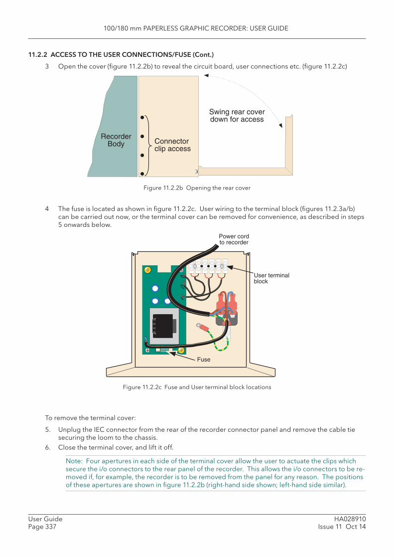
100/180 mm PAPERLESS GRAPHIC RECORDER: USER GUIDE
HA028910Issue 11 Oct 14
User GuidePage 337
11.2.2 ACCESS TO THE USER CONNECTIONS/FUSE (Cont.)
3 Open the cover (fi gure 11.2.2b) to reveal the circuit board, user connections etc. (fi gure 11.2.2c)
Figure 11.2.2b Opening the rear cover
4 The fuse is located as shown in fi gure 11.2.2c. User wiring to the terminal block (fi gures 11.2.3a/b) can be carried out now, or the terminal cover can be removed for convenience, as described in steps 5 onwards below.
Figure 11.2.2c Fuse and User terminal block locations
To remove the terminal cover:
5. Unplug the IEC connector from the rear of the recorder connector panel and remove the cable tie securing the loom to the chassis.
6. Close the terminal cover, and lift it off.
Note: Four apertures in each side of the terminal cover allow the user to actuate the clips which secure the i/o connectors to the rear panel of the recorder. This allows the i/o connectors to be re-moved if, for example, the recorder is to be removed from the panel for any reason. The positions of these apertures are shown in fi gure 11.2.2b (right-hand side shown; left-hand side similar).
RecorderBody
Swing rear coverdown for access
Connectorclip access
Power cordto recorder
Fuse
User terminalblock
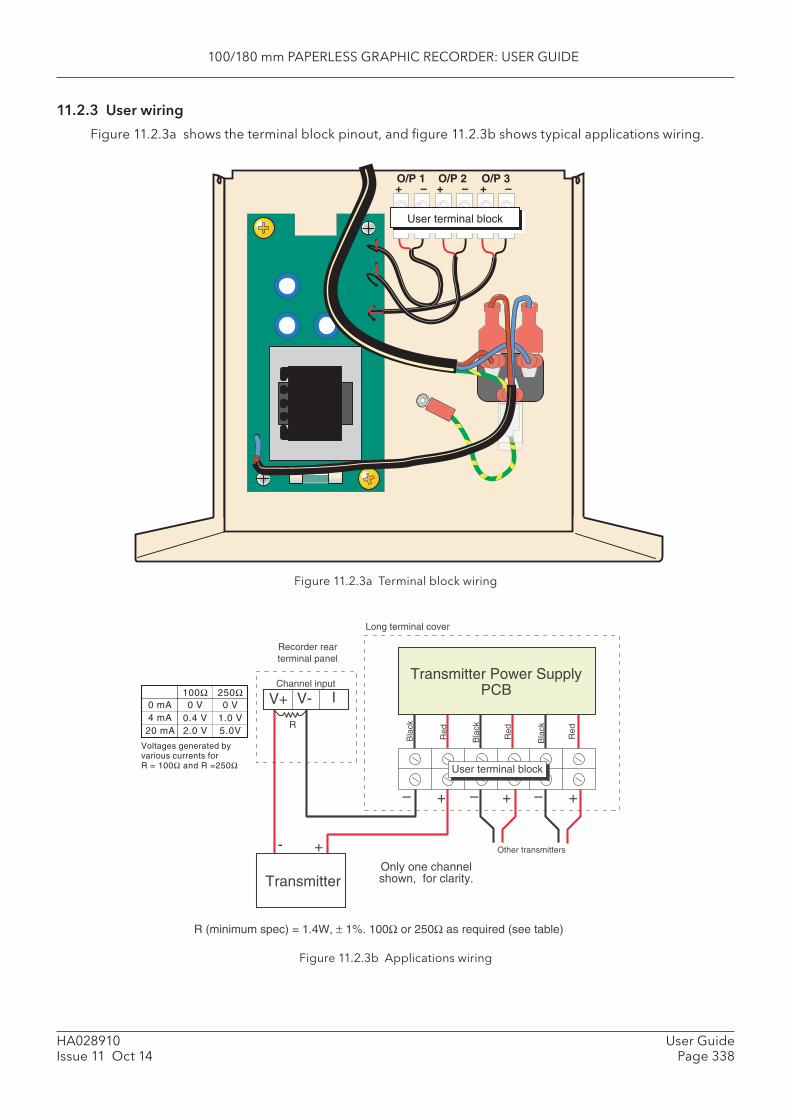
100/180 mm PAPERLESS GRAPHIC RECORDER: USER GUIDE
HA028910Issue 11 Oct 14
User GuidePage 338
11.2.3 User wiring
Figure 11.2.3a shows the terminal block pinout, and fi gure 11.2.3b shows typical applications wiring.
Figure 11.2.3a Terminal block wiring
Figure 11.2.3b Applications wiring
O/P 1+ –
O/P 2+ –
O/P 3+ –
User terminal block
Bla
ck
Bla
ck
Bla
ck
Red
Red
Red
– +
Transmitter
+- Other transmitters
V+ V-Channel input
– + – +
Only one channelshown, for clarity.
Long terminal cover
Recorder rearterminal panel
User terminal block
I
R
Transmitter Power SupplyPCB
0 mA4 mA
20 mA
0 V0.4 V2.0 V
0 V1.0 V5.0V
100Ω 250Ω
Voltages generated byvarious currents forR = 100Ω and R =250Ω
R (minimum spec) = 1.4W, ± 1%. 100Ω or 250Ω as required (see table)
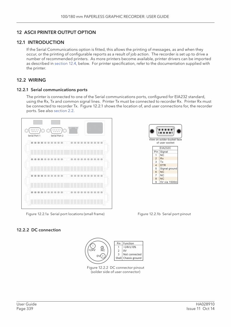
100/180 mm PAPERLESS GRAPHIC RECORDER: USER GUIDE
HA028910Issue 11 Oct 14
User GuidePage 339
Serial Port 1 Serial Port 2
EIA232CPin123456789
SignalNCRxTxDTRSignal groundNCNCNC5V via 1500Ω
16
59
View on solder-bucket faceof user socket
+24V
0V 2
31
NC
Pin Function1 +24V±10%2 0V3 Not connected
Shell Chassis ground
Figure 12.2.1a Serial port locations (small frame)
12 ASCII PRINTER OUTPUT OPTION
12.1 INTRODUCTIONIf the Serial Communications option is fi tted, this allows the printing of messages, as and when they occur, or the printing of confi gurable reports as a result of job action. The recorder is set up to drive a number of recommended printers. As more printers become available, printer drivers can be imported as described in section 12.4, below. For printer specifi cation, refer to the documentation supplied with the printer.
12.2 WIRING
12.2.1 Serial communications ports
The printer is connected to one of the Serial communications ports, confi gured for EIA232 standard, using the Rx, Tx and common signal lines. Printer Tx must be connected to recorder Rx. Printer Rx must be connected to recorder Tx. Figure 12.2.1 shows the location of, and user connections for, the recorder ports. See also section 2.2.
Figure 12.2.1b Serial port pinout
12. 2.2 DC connection
Figure 12.2.2 DC connector pinout(solder side of user connector)
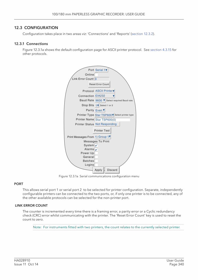
100/180 mm PAPERLESS GRAPHIC RECORDER: USER GUIDE
HA028910Issue 11 Oct 14
User GuidePage 340
Connection
Baud Rate
Stop Bits
Parity
Printer Type
Printer Name
Printer Status
SystemAlarms
Power Up
Select required Baud rate.
Select 1 or 2
Link Error Count
Reset Error Count
Select printer type
Printer Test
Print Messages From
Messages To Print
GeneralBatches
Logins
Apply Discard
Port
Online
Protocol
EIA232
9600
1
Even
Star TSP600
0
Star TSP600(0)
Not Responding
1) Group 1
Serial 1
ASCII Printer
12.3 CONFIGURATIONConfi guration takes place in two areas viz: ‘Connections’ and ‘Reports’ (section 12.3.2).
12.3.1 Connections
Figure 12.3.1a shows the default confi guration page for ASCII printer protocol. See section 4.3.15 for other protocols.
Figure 12.3.1a Serial communications confi guration menu
PORT
This allows serial port 1 or serial port 2 to be selected for printer confi guration. Separate, independently confi gurable printers can be connected to the two ports, or, if only one printer is to be connected, any of the other available protocols can be selected for the non-printer port.
LINK ERROR COUNT
The counter is incremented every time there is a framing error, a parity error or a Cyclic redundancy check (CRC) error whilst communicating with the printer. The ‘Reset Error Count’ key is used to reset the count to zero.
Note: For instruments fi tted with two printers, the count relates to the currently selected printer.
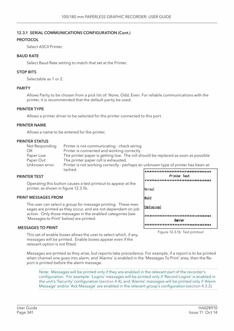
100/180 mm PAPERLESS GRAPHIC RECORDER: USER GUIDE
HA028910Issue 11 Oct 14
User GuidePage 341
Figure 12.3.1b Test printout
12.3.1 SERIAL COMMUNICATIONS CONFIGURATION (Cont.)
PROTOCOL
Select ASCII Printer.
BAUD RATE
Select Baud Rate setting to match that set at the Printer.
STOP BITS
Selectable as 1 or 2.
PARITY
Allows Parity to be chosen from a pick list of: None, Odd, Even. For reliable communications with the printer, it is recommended that the default parity be used.
PRINTER TYPE
Allows a printer driver to be selected for the printer connected to this port.
PRINTER NAME
Allows a name to be entered for the printer.
PRINTER STATUSNot Responding Printer is not communicating - check wiringOK Printer is connected and working correctlyPaper Low The printer paper is getting low. The roll should be replaced as soon as possiblePaper Out The printer paper roll is exhausted.Unknown error Printer is not working correctly - perhaps an unknown type of printer has been at-
tached.
PRINTER TEST
Operating this button causes a test printout to appear at the printer, as shown in fi gure 12.3.1b.
PRINT MESSAGES FROM
The user can select a group for message printing. These mes-sages are printed as they occur, and are not dependent on job action. Only those messages in the enabled categories (see ‘Messages to Print’ below) are printed.
MESSAGES TO PRINT
This set of enable boxes allows the user to select which, if any, messages will be printed. Enable boxes appear even if the relevant option is not fi tted.
Messages are printed as they arise, but reports take precedence. For example, if a report is to be printed when channel one goes into alarm, and ‘Alarms’ is enabled in the ‘Messages To Print’ area, then the Re-port is printed before the alarm message.
Note: Messages will be printed only if they are enabled in the relevant part of the recorder’s confi guration. For example: ‘Logins’ messages will be printed only if ‘Record Logins’ is enabled in the unit’s ‘Security’ confi guration (section 4.4), and ‘Alarms’ messages will be printed only if ‘Alarm Message’ and/or ‘Ack Message’ are enabled in the relevant group’s confi guration (section 4.3.2).
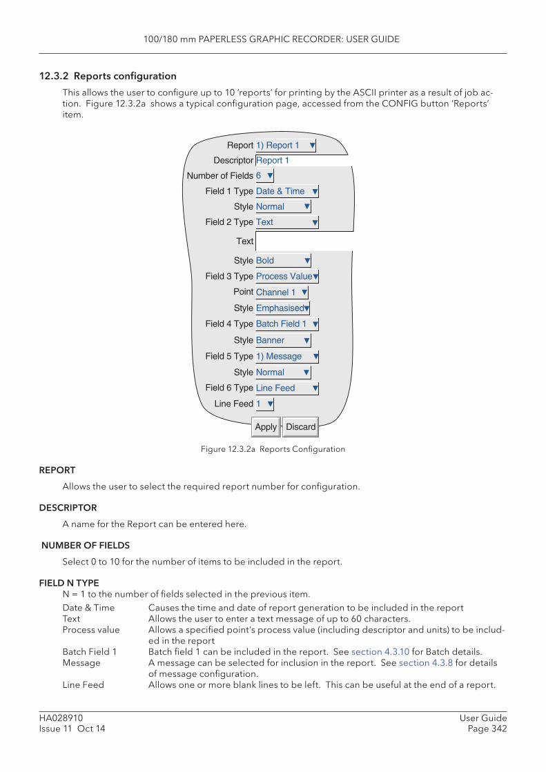
100/180 mm PAPERLESS GRAPHIC RECORDER: USER GUIDE
HA028910Issue 11 Oct 14
User GuidePage 342
Number of Fields
Report
Descriptor
Field 1 Type
Style
Field 2 Type
Text
Style
Field 3 Type
Point
Style
Field 4 Type
Style
Field 5 Type
Style
Field 6 Type
Line Feed
Apply Discard
Bold
Process Value
Channel 1
Emphasised
Batch Field 1
1) Message
Normal
Line Feed
1
1) Report 1
Date & Time
Normal
Text
Report 1
6
Banner
Figure 12.3.2a Reports Confi guration
REPORT
Allows the user to select the required report number for confi guration.
DESCRIPTOR
A name for the Report can be entered here.
NUMBER OF FIELDS
Select 0 to 10 for the number of items to be included in the report.
FIELD N TYPEN = 1 to the number of fi elds selected in the previous item. Date & Time Causes the time and date of report generation to be included in the report Text Allows the user to enter a text message of up to 60 characters. Process value Allows a specifi ed point’s process value (including descriptor and units) to be includ-
ed in the report Batch Field 1 Batch fi eld 1 can be included in the report. See section 4.3.10 for Batch details. Message A message can be selected for inclusion in the report. See section 4.3.8 for details
of message confi guration. Line Feed Allows one or more blank lines to be left. This can be useful at the end of a report.
12.3.2 Reports confi guration
This allows the user to confi gure up to 10 ‘reports’ for printing by the ASCII printer as a result of job ac-tion. Figure 12.3.2a shows a typical confi guration page, accessed from the CONFIG button ‘Reports’ item.
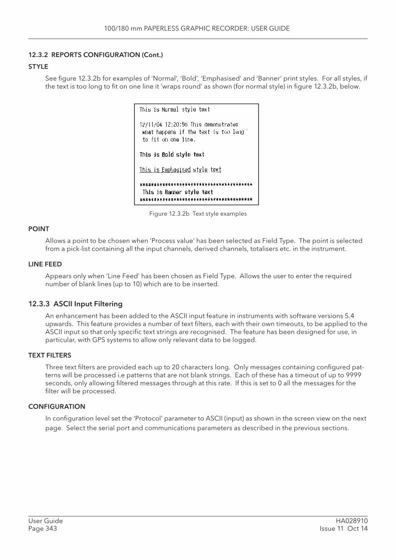
100/180 mm PAPERLESS GRAPHIC RECORDER: USER GUIDE
HA028910Issue 11 Oct 14
User GuidePage 343
12.3.2 REPORTS CONFIGURATION (Cont.)
STYLE
See fi gure 12.3.2b for examples of ‘Normal’, ‘Bold’, ‘Emphasised’ and ‘Banner’ print styles. For all styles, if the text is too long to fi t on one line it ‘wraps round’ as shown (for normal style) in fi gure 12.3.2b, below.
Figure 12.3.2b Text style examples
POINT
Allows a point to be chosen when ‘Process value’ has been selected as Field Type. The point is selected from a pick-list containing all the input channels, derived channels, totalisers etc. in the instrument.
LINE FEED
Appears only when ‘Line Feed’ has been chosen as Field Type. Allows the user to enter the required number of blank lines (up to 10) which are to be inserted.
12.3.3 ASCII Input Filtering
An enhancement has been added to the ASCII input feature in instruments with software versions 5.4 upwards. This feature provides a number of text fi lters, each with their own timeouts, to be applied to the ASCII input so that only specifi c text strings are recognised. The feature has been designed for use, in particular, with GPS systems to allow only relevant data to be logged.
TEXT FILTERS
Three text fi lters are provided each up to 20 characters long. Only messages containing confi gured pat-terns will be processed i.e patterns that are not blank strings. Each of these has a timeout of up to 9999 seconds, only allowing fi ltered messages through at this rate. If this is set to 0 all the messages for the fi lter will be processed.
CONFIGURATION
In confi guration level set the ‘Protocol’ parameter to ASCII (input) as shown in the screen view on the next page. Select the serial port and communications parameters as described in the previous sections.
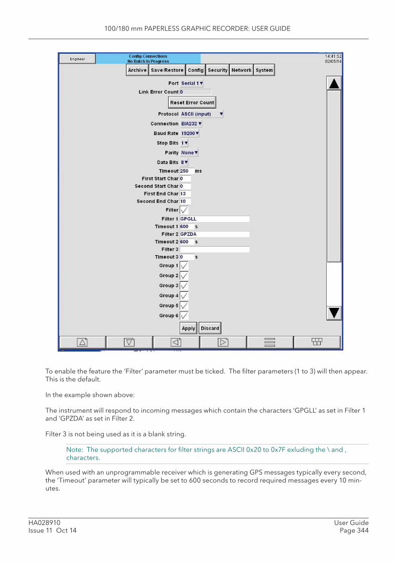
100/180 mm PAPERLESS GRAPHIC RECORDER: USER GUIDE
HA028910Issue 11 Oct 14
User GuidePage 344
To enable the feature the ‘Filter’ parameter must be ticked. The fi lter parameters (1 to 3) will then appear. This is the default.
In the example shown above:
The instrument will respond to incoming messages which contain the characters ‘GPGLL’ as set in Filter 1 and ‘GPZDA’ as set in Filter 2.
Filter 3 is not being used as it is a blank string.
Note: The supported characters for fi lter strings are ASCII 0x20 to 0x7F exluding the \ and , characters.
When used with an unprogrammable receiver which is generating GPS messages typically every second, the ‘Timeout’ parameter will typically be set to 600 seconds to record required messages every 10 min-utes.

100/180 mm PAPERLESS GRAPHIC RECORDER: USER GUIDE
HA028910Issue 11 Oct 14
User GuidePage 345
When used with a programmable receiver which is confi gured to generate GPS messages typically every 10 minutes, the ‘Timeout’ parameter can be set to 0 to disable it, so as to record required messages every 10 minutes.
‘Timeout’ can be set to different rates for each fi lter in which case the data will be recorded at the rates set for each fi lter.
When the instrument reboots the fi lter timeouts will reset, so the fi rst message received will be recorded (in a new history fi le), the timeouts will then come into effect.
Filter timeouts will also be reset when the instrument is reconfi gured or the clock is changed as per exist-ing “ASCII input” parameters.
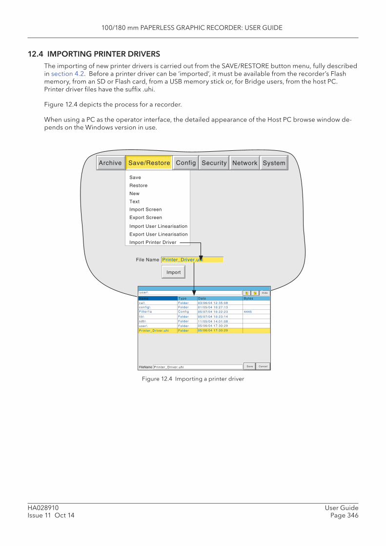
100/180 mm PAPERLESS GRAPHIC RECORDER: USER GUIDE
HA028910Issue 11 Oct 14
User GuidePage 346
File Name
Import
Printer_Driver.uhi
Save
Restore
New
Text
Archive SystemSave/Restore Config Security Network
Import Screen
Export Screen
Import User Linearisation
Export User Linearisation
Import Printer Driver
Save CancelFileName Pr inter_Dr iver .uh i
Hide
TypeName Date Bytes
\user \
ca l \conf ig \
l ib \
FolderFolder
Folder
sdb\ Folder
user \ Folder
03/06/04 12:35:0801/05/04 10:27:13
05/07/04 10:23:14
11/05/04 14:01:0805/06/04 17:30:29
Fi l ter1a Conf ig 05/07/04 10:22:23 4445
Pr inter_Dr iver .uh i Folder 05/06/04 17:30:29
12.4 IMPORTING PRINTER DRIVERS The importing of new printer drivers is carried out from the SAVE/RESTORE button menu, fully described in section 4.2. Before a printer driver can be ‘imported’, it must be available from the recorder’s Flash memory, from an SD or Flash card, from a USB memory stick or, for Bridge users, from the host PC. Printer driver fi les have the suffi x .uhi.
Figure 12.4 depicts the process for a recorder.
When using a PC as the operator interface, the detailed appearance of the Host PC browse window de-pends on the Windows version in use.
Figure 12.4 Importing a printer driver

100/180 mm PAPERLESS GRAPHIC RECORDER: USER GUIDE
HA028910Issue 11 Oct 14
User GuidePage 347
12.5 REPORT EXAMPLEThis example shows how to confi gure a report to be printed if any of channel 1 to channel 4 go into alarm. It is assumed that the Serial comms link with the printer has been successfully established.
The report is to include the process values of channels 1 to 4 and the time and date.
Note: The example assumes that the channels being confi gured are in their factory default state. Confi guration items not mentioned in the example (e.g. Scale Low) should be left at their default values.
12.5.1 Group Confi guration
Refer to section 4.3.2, as necessary.
GROUP NUMBER 1Descriptor = Colour mix.Alarm message = DisableDeselect all points except Channels 1 to 4.
12.5.2 Channel confi guration
Refer to section 4.3.3 as necessary
CHANNEL 1Input Type = TestScale High =100Units = %Descriptor = Red
Alarm 1
Enable = UnlatchedType = Absolute lowThreshold = 10
CHANNEL 2As channel 1, exceptDescriptor = Blue
CHANNEL 3As channel 1, exceptDescriptor = Green
CHANNEL 4As channel 1, exceptWaveform = Sine 4 minutesDescriptor = Orange
100/180 mm PAPERLESS GRAPHIC RECORDER: USER GUIDE
HA028910Issue 11 Oct 14
User GuidePage 348
12.5.3 Event Confi guration
Refer to section 4.3.6 as necessary
EVENT NUMBER 1Source 1 = Unack’d Alarm on GroupDescriptor = Paint low
Job number 1
Category = ReportSend Report to = Select required printerReport = 1) report 1On = Active
12.5.4 Report Confi gurationDescriptor = Paint LowNumber of fi elds = 8Field 1 Type = Text Text = ‘Paint Low Warning’ Style = BannerField 2 Type = Line Feed Line Feed = 2Field 3 Type = Date & Time Style = NormalField 4 Type = Process Value Point = Red
Style = NormalField 5 Type = Process Value Point = Blue
Style = NormalField 6 Type = Process Value Point = Green
Style = NormalField 7 Type = Process Value Point = Orange
Style = NormalField 8 Type = Line feed Line Feed = 5
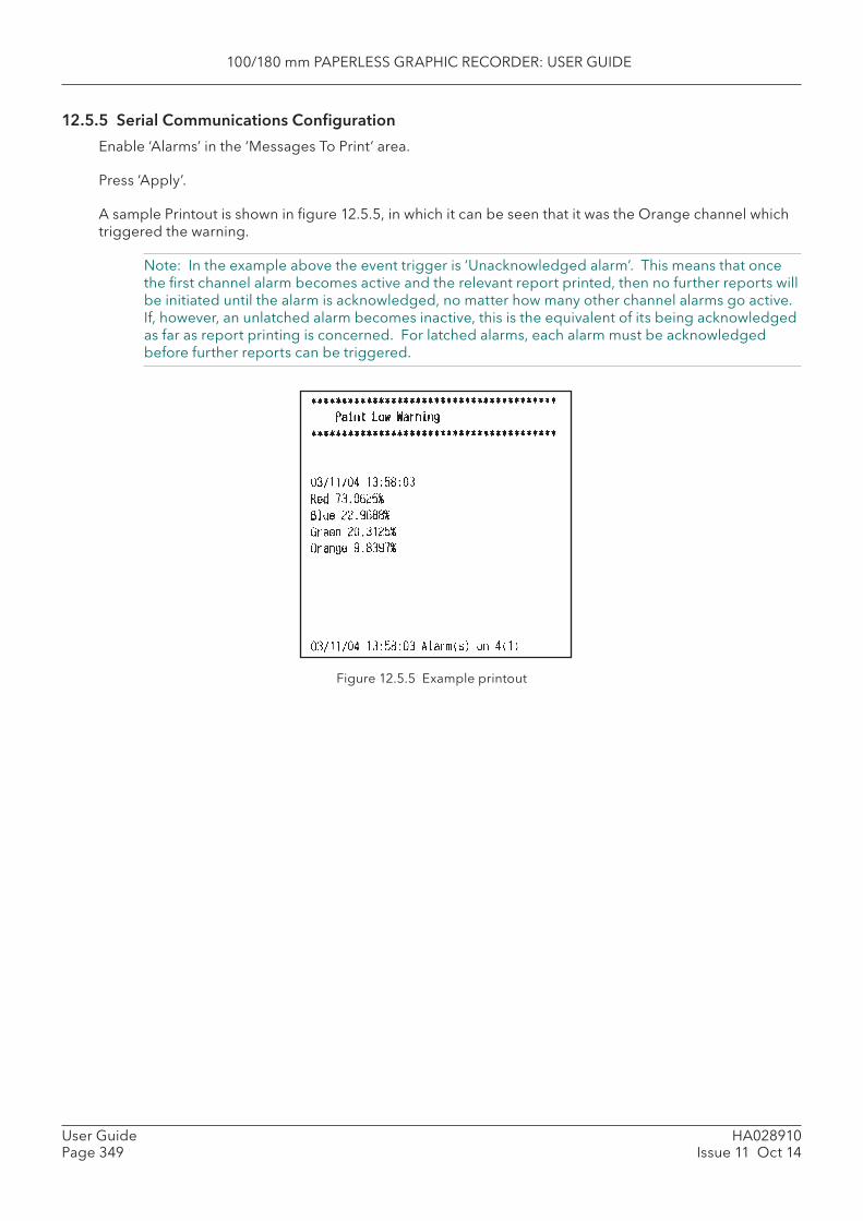
100/180 mm PAPERLESS GRAPHIC RECORDER: USER GUIDE
HA028910Issue 11 Oct 14
User GuidePage 349
12.5.5 Serial Communications Confi guration
Enable ‘Alarms’ in the ‘Messages To Print’ area.
Press ‘Apply’.
A sample Printout is shown in fi gure 12.5.5, in which it can be seen that it was the Orange channel which triggered the warning.
Note: In the example above the event trigger is ‘Unacknowledged alarm’. This means that once the fi rst channel alarm becomes active and the relevant report printed, then no further reports will be initiated until the alarm is acknowledged, no matter how many other channel alarms go active. If, however, an unlatched alarm becomes inactive, this is the equivalent of its being acknowledged as far as report printing is concerned. For latched alarms, each alarm must be acknowledged before further reports can be triggered.
Figure 12.5.5 Example printout
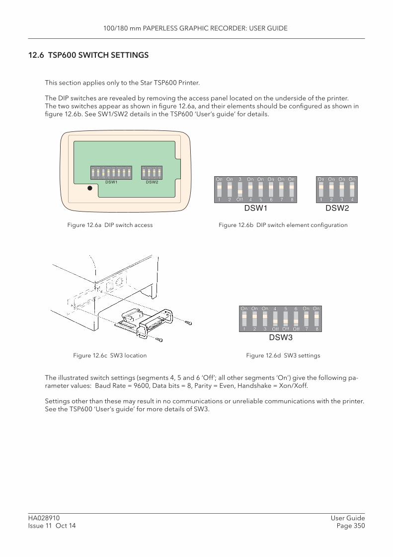
100/180 mm PAPERLESS GRAPHIC RECORDER: USER GUIDE
HA028910Issue 11 Oct 14
User GuidePage 350
DSW1 DSW2
DSW1 DSW2
DSW3
12.6 TSP600 SWITCH SETTINGS
This section applies only to the Star TSP600 Printer.
The DIP switches are revealed by removing the access panel located on the underside of the printer. The two switches appear as shown in fi gure 12.6a, and their elements should be confi gured as shown in fi gure 12.6b. See SW1/SW2 details in the TSP600 ‘User’s guide’ for details.
Figure 12.6c SW3 location Figure 12.6d SW3 settings
Figure 12.6a DIP switch access Figure 12.6b DIP switch element confi guration
The illustrated switch settings (segments 4, 5 and 6 ‘Off’; all other segments ‘On’) give the following pa-rameter values: Baud Rate = 9600, Data bits = 8, Parity = Even, Handshake = Xon/Xoff.
Settings other than these may result in no communications or unreliable communications with the printer. See the TSP600 ‘User’s guide’ for more details of SW3.
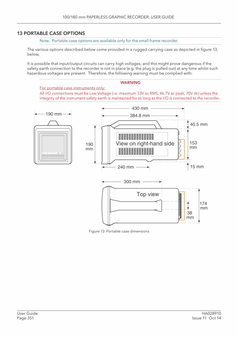
100/180 mm PAPERLESS GRAPHIC RECORDER: USER GUIDE
HA028910Issue 11 Oct 14
User GuidePage 351
13 PORTABLE CASE OPTIONS Note: Portable case options are available only for the small frame recorder.
The various options described below come provided in a rugged carrying case as depicted in fi gure 13, below,
It is possible that input/output circuits can carry high voltages, and this might prove dangerous if the safety earth connection to the recorder is not in place (e.g. the plug is pulled out) at any time whilst such hazardous voltages are present. Therefore, the following warning must be complied with:
WARNINGFor portable case instruments only:All I/O connections must be Low Voltage (i.e. maximum 33V ac RMS, 46.7V ac peak, 70V dc) unless the integrity of the instrument safety earth is maintained for as long as the I/O is connected to the recorder.
Figure 13 Portable case dimensions
190 mm
Top view
384.8 mm
190mm
40.5 mm
153mm
15 mm240 mm
300 mm
38 mm
174 mm
View on right-hand side
430 mm
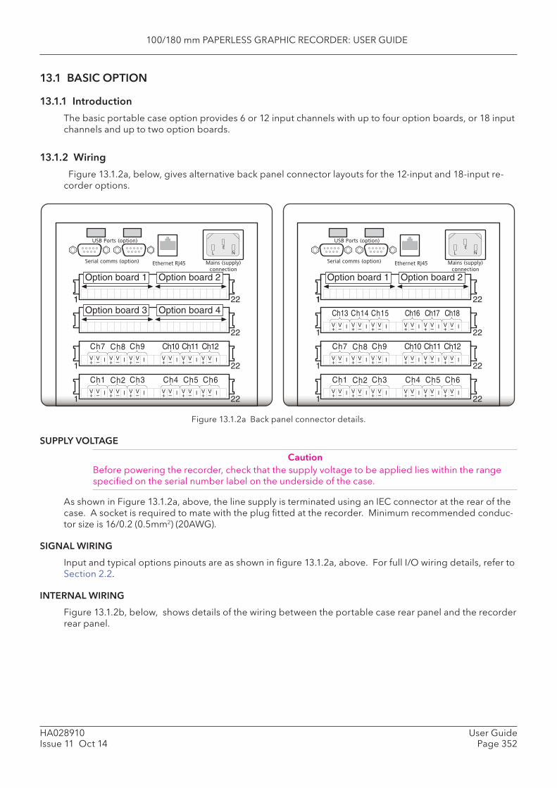
100/180 mm PAPERLESS GRAPHIC RECORDER: USER GUIDE
HA028910Issue 11 Oct 14
User GuidePage 352
13.1 BASIC OPTION
13.1.1 Introduction
The basic portable case option provides 6 or 12 input channels with up to four option boards, or 18 input channels and up to two option boards.
13.1.2 Wiring
Figure 13.1.2a, below, gives alternative back panel connector layouts for the 12-input and 18-input re-corder options.
Figure 13.1.2a Back panel connector details.
SUPPLY VOLTAGE
CautionBefore powering the recorder, check that the supply voltage to be applied lies within the range specifi ed on the serial number label on the underside of the case.
As shown in Figure 13.1.2a, above, the line supply is terminated using an IEC connector at the rear of the case. A socket is required to mate with the plug fi tted at the recorder. Minimum recommended conduc-tor size is 16/0.2 (0.5mm2) (20AWG).
SIGNAL WIRING
Input and typical options pinouts are as shown in fi gure 13.1.2a, above. For full I/O wiring details, refer to Section 2.2.
INTERNAL WIRING
Figure 13.1.2b, below, shows details of the wiring between the portable case rear panel and the recorder rear panel.
1 221
22
1 22
Option board 1 Option board 2
Option board 3 Option board 4
IV+
V– IV
+V– IV
+V–
Ch1 Ch2 Ch3 Ch4 Ch5 Ch6IV
+V– IV
+V– IV
+V–
1 22IV
+V– IV
+V– IV
+V– IV
+V– IV
+V– IV
+V–
Ch7 Ch8 Ch9 Ch11 Ch12Ch10
Serial comms (option)
USB Ports (option)
Ethernet RJ45
L N
E
Mains (supply)
connection
1 221
1 22
Option board 1 Option board 2
IV+
V– IV
+V– IV
+V–
Ch1 Ch2 Ch3 Ch4 Ch5 Ch6IV
+V– IV
+V– IV
+V–
1 22IV
+V– IV
+V– IV
+V– IV
+V– IV
+V– IV
+V–
Ch7 Ch8 Ch9 Ch11 Ch12Ch10
Serial comms (option)
USB Ports (option)
Ethernet RJ45
L N
E
Mains (supply)
connection
1 22IV
+V– IV
+V– IV
+V– IV
+V– IV
+V– IV
+V–
Ch13 Ch17 Ch18Ch16Ch14 Ch15
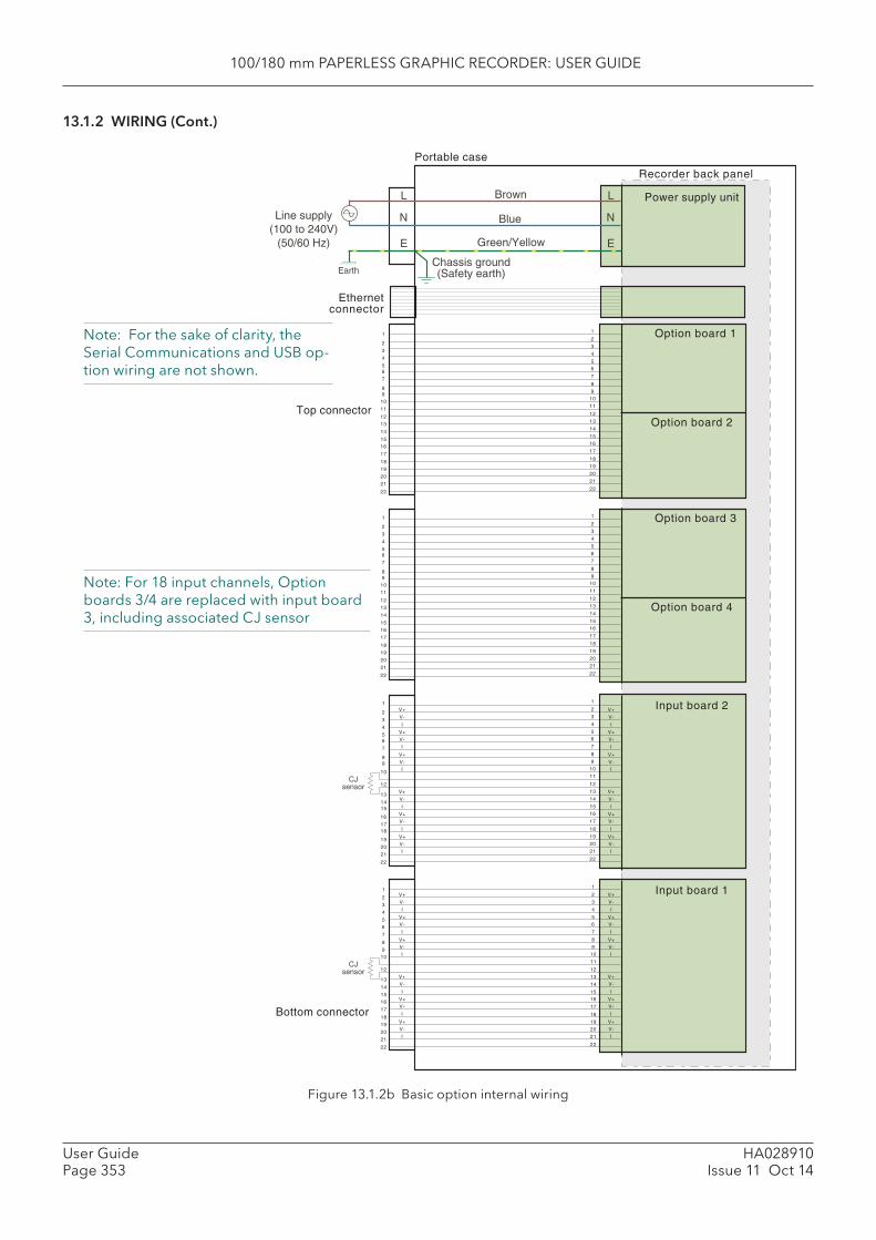
100/180 mm PAPERLESS GRAPHIC RECORDER: USER GUIDE
HA028910Issue 11 Oct 14
User GuidePage 353
13.1.2 WIRING (Cont.)
Figure 13.1.2b Basic option internal wiring
1
2
3
4
56
7
89
10
12
13
1415
16
1718
19
20
21
22
Bottom connector
1
2
3
4
56
7
8
910
12
13
14
1516
17
18
19
20
21
22
Top connectorOption board 2
Power supply unitBrown
Blue
Green/Yellow
L
N
E
Line supply(100 to 240V)
(50/60 Hz)
EarthChassis ground(Safety earth)
1
2
3
4
56
7
8
910
11
12
13
14
1516
17
18
19
20
21
22
Option board 1
Option board 4
1
2
3
4
56
7
8
910
11
12
13
14
1516
17
18
19
20
21
22
Option board 31
2
3
4
56
7
89
10
11
12
13
14
1516
17
18
19
20
21
22
Input board 2
1
2
3
4
56
7
8
910
11
12
13
14
1516
17
18
19
20
21
22
Input board 1
CJsensor
Recorder back panel
Portable case
L
N
E
V+
V-
I
V+V-
I
V+
V-I
V+
V-
I
V+V-
I
V+
V-I
CJsensor
V+
V-
I
V+V-
I
V+
V-I
V+
V-
I
V+V-
I
V+
V-I
1
2
3
4
56
7
89
10
11
12
13
14
1516
17
18
19
20
21
22
V+
V-
I
V+V-
I
V+
V-I
V+
V-
I
V+V-
I
V+
V-I
1
2
3
4
56
7
8
910
11
12
13
14
1516
17
18
19
20
21
22
V+
V-
I
V+V-
I
V+
V-I
V+
V-
I
V+V-
I
V+
V-I
Ethernetconnector
Note: For 18 input channels, Option boards 3/4 are replaced with input board 3, including associated CJ sensor
Note: For the sake of clarity, the Serial Communications and USB op-tion wiring are not shown.

100/180 mm PAPERLESS GRAPHIC RECORDER: USER GUIDE
HA028910Issue 11 Oct 14
User GuidePage 354
13.2 TRANSMITTER POWER SUPPLY (TRS) OPTIONThis option is identical with the 6/12 channel basic option described in section 13.1, above except that one of the option slots is used for TRS output. The TRS pinout is given in fi gure 13.2, below.
Note: Only one transmitter power supply can be fi tted in the portable case, and may be termi-nated only at option slot 2 OR option slot 4 (if available).
Figure 13.2 TRS pinout
13.2.1 Internal wiring
Figure 13.2.1 shows wiring details between the recorder and the back panel connectors.
1 2 3 4 5 6 7 8 9 10 11 12 13 14 15 16 17 18 19 20 21 22
+V 0V+V 0V+V0V
Pinout for TRS(must use option slot 2 OR 4)
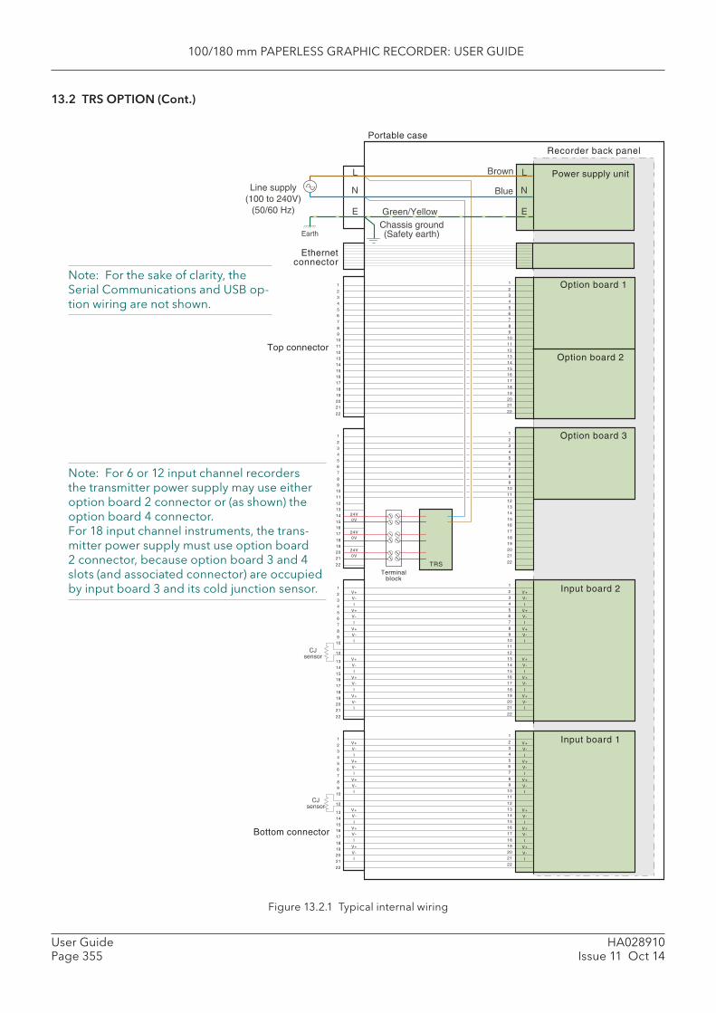
100/180 mm PAPERLESS GRAPHIC RECORDER: USER GUIDE
HA028910Issue 11 Oct 14
User GuidePage 355
13.2 TRS OPTION (Cont.)
Figure 13.2.1 Typical internal wiring
Bottom connector
Top connector
V+
V-
I
V+V-
I
V+
V-I
V+
V-
I
V+V-
I
V+
V-I
Option board 2
Power supply unitBrown
Blue
Green/Yellow
L
N
E
Line supply(100 to 240V)
(50/60 Hz)
EarthChassis ground(Safety earth)
CJsensor
1
2
3
4
56
7
8
910
11
12
13
14
1516
17
18
19
20
21
22
Option board 1
Input board 2
Input board 1
CJsensor
Recorder back panel
Portable case
L
N
E
0V24V
0V24V
0V24V
1
2
3
4
56
7
8
910
12
13
14
1516
17
18
19
20
21
22
1
2
3
4
56
7
8
910
12
13
14
1516
17
18
19
20
21
22
1
2
3
4
56
7
8
910
11
12
13
14
1516
17
18
19
20
21
22
1
2
3
4
56
7
8
910
11
12
13
14
1516
17
18
19
20
21
22
Terminalblock
TRS
V+
V-
I
V+V-
I
V+
V-I
V+
V-
I
V+V-
I
V+
V-I
V+
V-
I
V+V-
I
V+
V-I
V+
V-
I
V+V-
I
V+
V-I
V+
V-
I
V+V-
I
V+
V-I
V+
V-
I
V+V-
I
V+
V-I
Option board 31
2
3
4
56
7
8
910
11
12
13
14
1516
17
18
19
20
21
22
1
2
3
4
56
7
8
910
11
12
13
14
1516
17
18
19
20
21
22
1
2
3
4
56
7
8
910
11
12
13
14
1516
17
18
19
20
21
22
Ethernetconnector
Note: For the sake of clarity, the Serial Communications and USB op-tion wiring are not shown.
Note: For 6 or 12 input channel recorders the transmitter power supply may use either option board 2 connector or (as shown) the option board 4 connector. For 18 input channel instruments, the trans-mitter power supply must use option board 2 connector, because option board 3 and 4 slots (and associated connector) are occupied by input board 3 and its cold junction sensor.
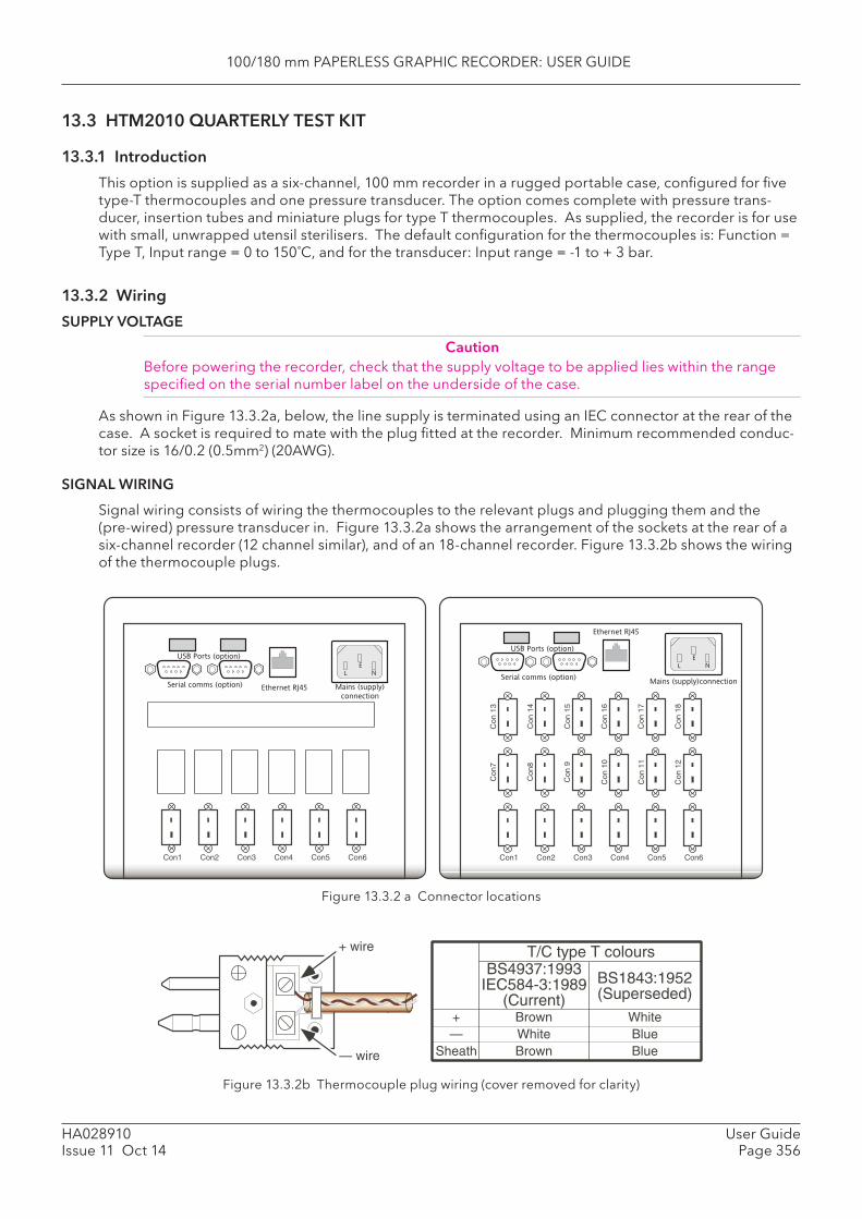
100/180 mm PAPERLESS GRAPHIC RECORDER: USER GUIDE
HA028910Issue 11 Oct 14
User GuidePage 356
13.3 HTM2010 QUARTERLY TEST KIT
13.3.1 Introduction
This option is supplied as a six-channel, 100 mm recorder in a rugged portable case, confi gured for fi ve type-T thermocouples and one pressure transducer. The option comes complete with pressure trans-ducer, insertion tubes and miniature plugs for type T thermocouples. As supplied, the recorder is for use with small, unwrapped utensil sterilisers. The default confi guration for the thermocouples is: Function = Type T, Input range = 0 to 150˚C, and for the transducer: Input range = -1 to + 3 bar.
13.3.2 Wiring
SUPPLY VOLTAGE
CautionBefore powering the recorder, check that the supply voltage to be applied lies within the range specifi ed on the serial number label on the underside of the case.
As shown in Figure 13.3.2a, below, the line supply is terminated using an IEC connector at the rear of the case. A socket is required to mate with the plug fi tted at the recorder. Minimum recommended conduc-tor size is 16/0.2 (0.5mm2) (20AWG).
SIGNAL WIRING
Signal wiring consists of wiring the thermocouples to the relevant plugs and plugging them and the (pre-wired) pressure transducer in. Figure 13.3.2a shows the arrangement of the sockets at the rear of a six-channel recorder (12 channel similar), and of an 18-channel recorder. Figure 13.3.2b shows the wiring of the thermocouple plugs.
Figure 13.3.2 a Connector locations
Figure 13.3.2b Thermocouple plug wiring (cover removed for clarity)
Con1 Con2 Con3 Con4 Con5 Con6
Serial comms (option)
USB Ports (option)
Ethernet RJ45
L N
E
Mains (supply)
connection
Con1 Con2 Con3 Con4 Con5 Con6
Con
7
Con
8
Con
9
Con
10
Con
11
Con
12
Serial comms (option)
USB Ports (option)
Ethernet RJ45
L N
E
Con
13
Con
14
Con
15
Con
16
Con
17
Con
18
Mains (supply)connection
BrownWhiteBrown
+ wire
— wire
BS1843:1952(Superseded)
BS4937:1993IEC584-3:1989
(Current)WhiteBlueBlue
+—
Sheath
T/C type T colours
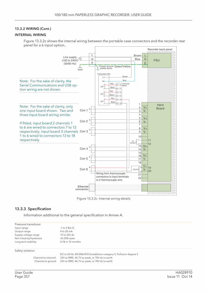
100/180 mm PAPERLESS GRAPHIC RECORDER: USER GUIDE
HA028910Issue 11 Oct 14
User GuidePage 357
Brown
Blue
BrownBlue
Green/Yellow
Red
Black
Red
Black
Red
Black
O/P 3
O/P 2
O/P 1
+
+
+
N
L
Transmitter PSU
123456789
10
131415161718
1920
2122
InputBoard
L
NE
Line supply(100 to 240V)
(50/60 Hz)
Recorder back panel
PSU
CJsensor
V+V--
+
-+
-+
-+
V+V-
V+V-
V+V-Con 1
Con 2
Con 3
Con 6 Shunt
Wiring from thermocoupleconnectors to input terminalsis in thermocouple wire
Chassis ground(safety earth)
Earth
-+
Con 4
-+
Con 5V+V-
V+V-
1112
LN
E
TerminalBlock
Ethernetconnector
13.3.2 WIRING (Cont.)
INTERNAL WIRING
Figure 13.3.2c shows the internal wiring between the portable case connectors and the recorder rear panel for a 6 input option..
Figure 13.3.2c Internal wiring details
13.3.3 Specifi cation
Information additional to the general specifi cation in Annex A.
Pressure transducerInput range -1 to 3 Bar GOutput range 4 to 20 mASupply voltage range 12 to 32V dcNon linearity/hysteresis ≤0.25% spanLong term stability 0.1% in 12 months
Safety isolation DC to 65 Hz: BS EN61010 (Installation category II; Pollution degree 2 Channel to channel: 33V ac RMS, 46.7V ac peak, or 70V dc to earth Channel to ground 33V ac RMS, 46.7V ac peak, or 70V dc to earth
Note: For the sake of clarity, the Serial Communications and USB op-tion wiring are not shown.
Note: For the sake of clarity, only one input board shown. Two and three input board wiring similar.
If fi tted, input board 2 channels 1 to 6 are wired to connectors 7 to 12 respectively; input board 3 channels 1 to 6 wired to connectors 13 to 18 respectively.
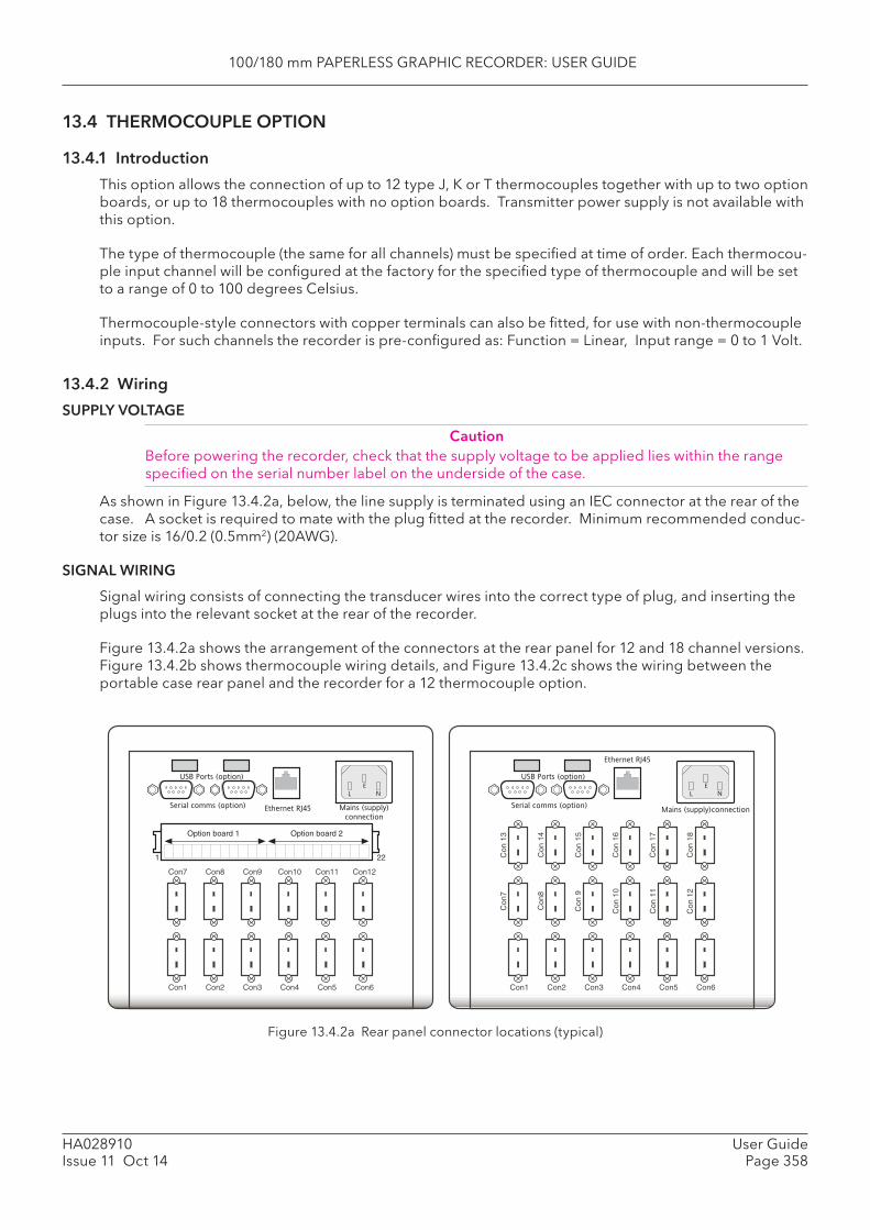
100/180 mm PAPERLESS GRAPHIC RECORDER: USER GUIDE
HA028910Issue 11 Oct 14
User GuidePage 358
13.4 THERMOCOUPLE OPTION
13.4.1 Introduction
This option allows the connection of up to 12 type J, K or T thermocouples together with up to two option boards, or up to 18 thermocouples with no option boards. Transmitter power supply is not available with this option.
The type of thermocouple (the same for all channels) must be specifi ed at time of order. Each thermocou-ple input channel will be confi gured at the factory for the specifi ed type of thermocouple and will be set to a range of 0 to 100 degrees Celsius.
Thermocouple-style connectors with copper terminals can also be fi tted, for use with non-thermocouple inputs. For such channels the recorder is pre-confi gured as: Function = Linear, Input range = 0 to 1 Volt.
13.4.2 Wiring
SUPPLY VOLTAGE
CautionBefore powering the recorder, check that the supply voltage to be applied lies within the range specifi ed on the serial number label on the underside of the case.
As shown in Figure 13.4.2a, below, the line supply is terminated using an IEC connector at the rear of the case. A socket is required to mate with the plug fi tted at the recorder. Minimum recommended conduc-tor size is 16/0.2 (0.5mm2) (20AWG).
SIGNAL WIRING
Signal wiring consists of connecting the transducer wires into the correct type of plug, and inserting the plugs into the relevant socket at the rear of the recorder.
Figure 13.4.2a shows the arrangement of the connectors at the rear panel for 12 and 18 channel versions. Figure 13.4.2b shows thermocouple wiring details, and Figure 13.4.2c shows the wiring between the portable case rear panel and the recorder for a 12 thermocouple option.
Figure 13.4.2a Rear panel connector locations (typical)
Con1 Con2 Con3 Con4 Con5 Con6
1 22
Option board 1 Option board 2
Con7 Con8 Con9 Con10 Con11 Con12
Serial comms (option)
USB Ports (option)
Ethernet RJ45
L N
E
Mains (supply)
connection
Con1 Con2 Con3 Con4 Con5 Con6
Con
7
Con
8
Con
9
Con
10
Con
11
Con
12
Serial comms (option)
USB Ports (option)
Ethernet RJ45
L N
E
Con
13
Con
14
Con
15
Con
16
Con
17
Con
18
Mains (supply)connection
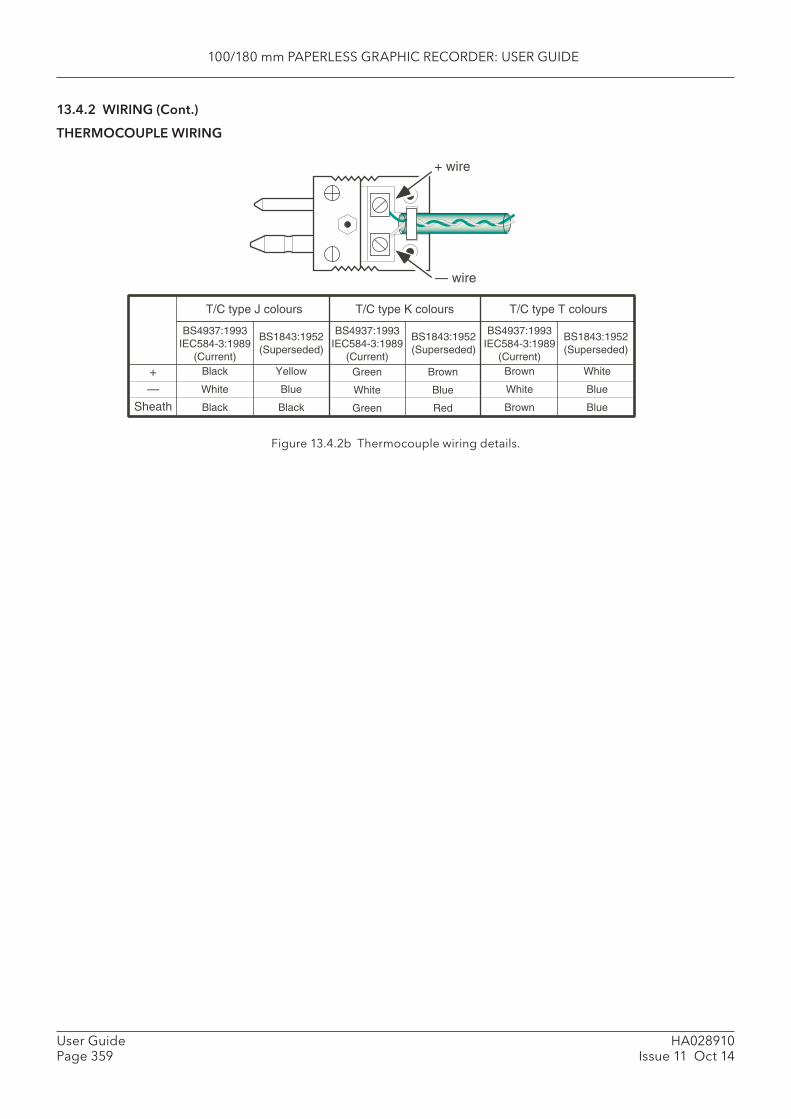
100/180 mm PAPERLESS GRAPHIC RECORDER: USER GUIDE
HA028910Issue 11 Oct 14
User GuidePage 359
13.4.2 WIRING (Cont.)
THERMOCOUPLE WIRING
Figure 13.4.2b Thermocouple wiring details.
Black
White
Black
BS1843:1952(Superseded)
BS4937:1993IEC584-3:1989
(Current)Yellow
Blue
Black
+
—
Sheath
T/C type J colours
Green
White
Green
Brown
Blue
Red
Brown
White
Brown
White
Blue
Blue
+ wire
— wire
T/C type K colours
BS1843:1952(Superseded)
BS4937:1993IEC584-3:1989
(Current)
T/C type T colours
BS1843:1952(Superseded)
BS4937:1993IEC584-3:1989
(Current)
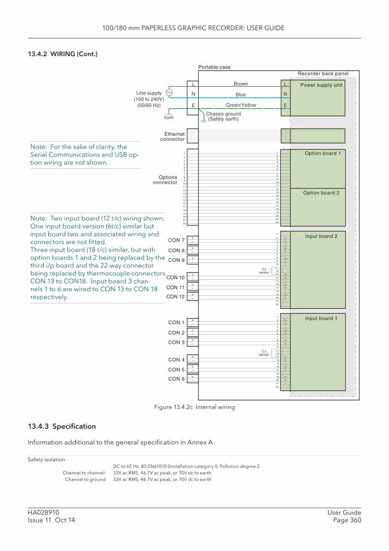
100/180 mm PAPERLESS GRAPHIC RECORDER: USER GUIDE
HA028910Issue 11 Oct 14
User GuidePage 360
13.4.2 WIRING (Cont.)
Figure 13.4.2c Internal wiring
13.4.3 Specifi cation
Information additional to the general specifi cation in Annex A.
Safety isolation DC to 65 Hz: BS EN61010 (Installation category II; Pollution degree 2 Channel to channel: 33V ac RMS, 46.7V ac peak, or 70V dc to earth Channel to ground 33V ac RMS, 46.7V ac peak, or 70V dc to earth
Optionsconnector
Input board 2
1
2
3
4
56
7
8
910
11
12
13
14
1516
17
18
19
20
21
22
Input board 1
V+
V-
I
V+V-
I
V+
V-I
V+
V-
I
V+V-
I
V+
V-I
1
2
3
4
56
7
8
910
11
12
13
14
1516
17
18
19
20
21
22
V+
V-
I
V+V-
I
V+
V-I
V+
V-
I
V+V-
I
V+
V-I
CON 7
CON 8
CON 9
CON 10
CON 11
CON 12
CJsensor
+-
+-
+-
+-
+-
+-
CON 1
CON 2
CON 3
CON 4
CON 5
CON 6
CJsensor
Option board 2
Power supply unitBrown
Blue
Green/Yellow
L
N
E
Line supply(100 to 240V)
(50/60 Hz)
EarthChassis ground(Safety earth)
1
2
3
4
56
7
8
910
11
12
13
14
1516
17
18
19
20
21
22
Option board 1
Recorder back panelPortable case
L
N
E
1
2
3
4
56
7
89
10
11
12
13
14
1516
17
18
19
20
21
22
Ethernetconnector
+-
+-
+-
+-
+-
+-
Note: For the sake of clarity, the Serial Communications and USB op-tion wiring are not shown.
Note: Two input board (12 t/c) wiring shown. One input board version (6t/c) similar but input board two and associated wiring and connectors are not fi tted. Three input board (18 t/c) similar, but with option boards 1 and 2 being replaced by the third i/p board and the 22-way connector being replaced by thermocouple connectors CON 13 to CON18. Input board 3 chan-nels 1 to 6 are wired to CON 13 to CON 18 respectively.
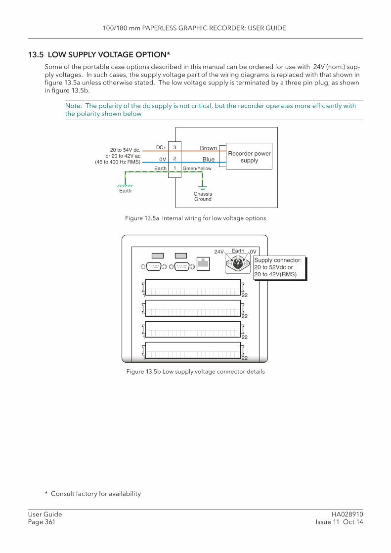
100/180 mm PAPERLESS GRAPHIC RECORDER: USER GUIDE
HA028910Issue 11 Oct 14
User GuidePage 361
13.5 LOW SUPPLY VOLTAGE OPTION*Some of the portable case options described in this manual can be ordered for use with 24V (nom.) sup-ply voltages. In such cases, the supply voltage part of the wiring diagrams is replaced with that shown in fi gure 13.5a unless otherwise stated. The low voltage supply is terminated by a three pin plug, as shown in fi gure 13.5b.
Note: The polarity of the dc supply is not critical, but the recorder operates more effi ciently with the polarity shown below
Figure 13.5a Internal wiring for low voltage options
Figure 13.5b Low supply voltage connector details
Blue
Brown
Green/YellowEarth
ChassisGround
Earth
3
2
1
DC+
0VRecorder power
supply
20 to 54V dc,or 20 to 42V ac
(45 to 400 Hz RMS)
1 221
22
1 22
1 22
0V24V Earth
Supply connector:20 to 52Vdc or20 to 42V(RMS)
* Consult factory for availability
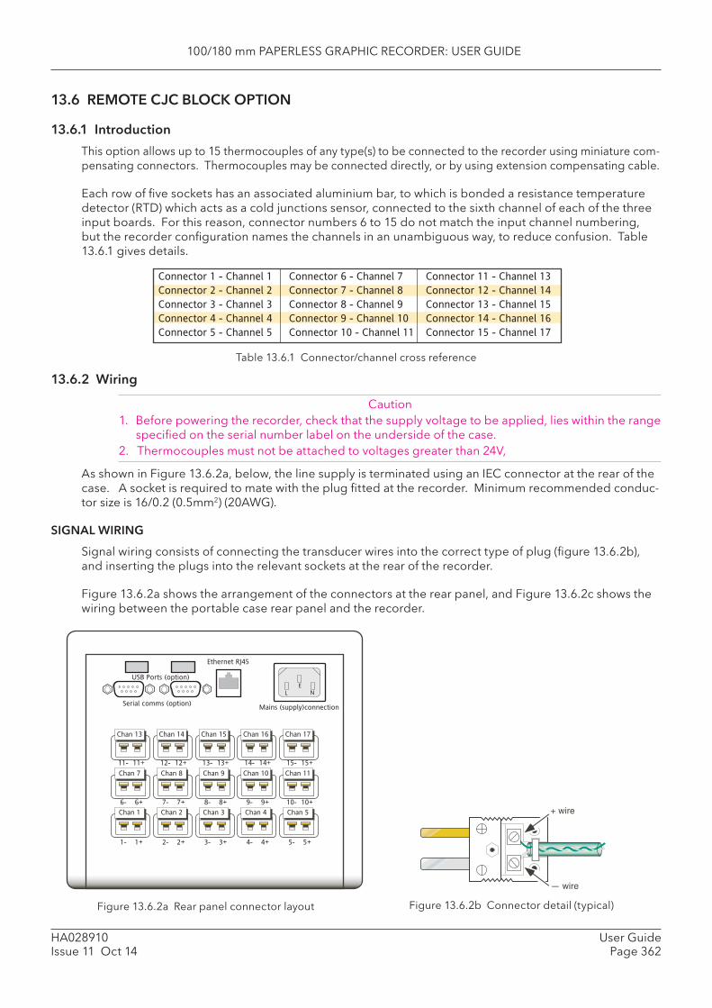
100/180 mm PAPERLESS GRAPHIC RECORDER: USER GUIDE
HA028910Issue 11 Oct 14
User GuidePage 362
13.6 REMOTE CJC BLOCK OPTION
13.6.1 Introduction
This option allows up to 15 thermocouples of any type(s) to be connected to the recorder using miniature com-pensating connectors. Thermocouples may be connected directly, or by using extension compensating cable.
Each row of fi ve sockets has an associated aluminium bar, to which is bonded a resistance temperature detector (RTD) which acts as a cold junctions sensor, connected to the sixth channel of each of the three input boards. For this reason, connector numbers 6 to 15 do not match the input channel numbering, but the recorder confi guration names the channels in an unambiguous way, to reduce confusion. Table 13.6.1 gives details.
Figure 13.6.2a Rear panel connector layout
Serial comms (option)
USB Ports (option)
Ethernet RJ45
L N
E
Mains (supply)connection
1- 1+
Chan 1 Chan 2 Chan 3 Chan 4 Chan 5
Chan 7 Chan 8 Chan 9 Chan 10 Chan 11
Chan 13 Chan 14 Chan 15 Chan 16 Chan 17
6- 6+
11- 11+
2- 2+
7- 7+
12- 12+
3- 3+
8- 8+
13- 13+
4- 4+
9- 9+
14- 14+
5- 5+
10- 10+
15- 15+
+ wire
Figure 13.6.2b Connector detail (typical)
Table 13.6.1 Connector/channel cross reference
13.6.2 Wiring
Caution1. Before powering the recorder, check that the supply voltage to be applied, lies within the range
specifi ed on the serial number label on the underside of the case.2. Thermocouples must not be attached to voltages greater than 24V,
As shown in Figure 13.6.2a, below, the line supply is terminated using an IEC connector at the rear of the case. A socket is required to mate with the plug fi tted at the recorder. Minimum recommended conduc-tor size is 16/0.2 (0.5mm2) (20AWG).
SIGNAL WIRING
Signal wiring consists of connecting the transducer wires into the correct type of plug (fi gure 13.6.2b), and inserting the plugs into the relevant sockets at the rear of the recorder.
Figure 13.6.2a shows the arrangement of the connectors at the rear panel, and Figure 13.6.2c shows the wiring between the portable case rear panel and the recorder.
Connector 1 - Channel 1
Connector 2 - Channel 2
Connector 3 - Channel 3
Connector 4 - Channel 4
Connector 5 - Channel 5
Connector 6 - Channel 7
Connector 7 - Channel 8
Connector 8 - Channel 9
Connector 9 - Channel 10
Connector 10 - Channel 11
Connector 11 - Channel 13
Connector 12 - Channel 14
Connector 13 - Channel 15
Connector 14 - Channel 16
Connector 15 - Channel 17
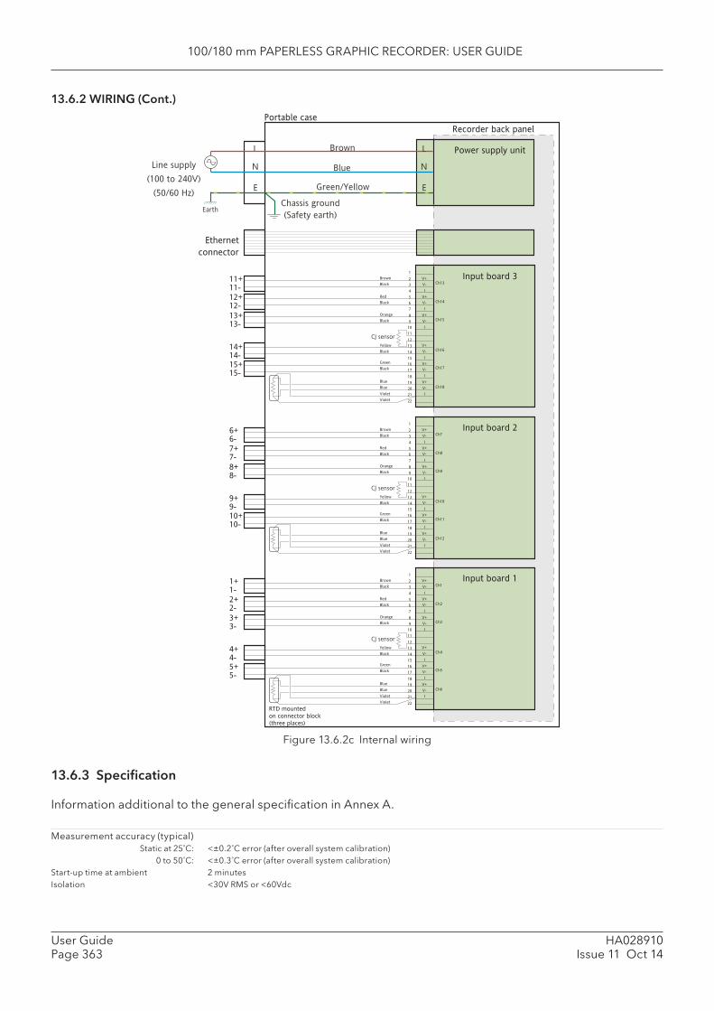
100/180 mm PAPERLESS GRAPHIC RECORDER: USER GUIDE
HA028910Issue 11 Oct 14
User GuidePage 363
13.6.2 WIRING (Cont.)
Figure 13.6.2c Internal wiring
13.6.3 Specifi cation
Information additional to the general specifi cation in Annex A.
Measurement accuracy (typical) Static at 25˚C: <±0.2˚C error (after overall system calibration) 0 to 50˚C: <±0.3˚C error (after overall system calibration)Start-up time at ambient 2 minutesIsolation <30V RMS or <60Vdc
Input board 2
1
2
3
4
5
6
7
8
9
10
11
12
13
14
15
16
17
18
19
20
21
22
Input board 1V+
V-
I
V+
V-
I
V+
V-
I
V+
V-
I
V+
V-
I
V+
V-
I
CJ sensor
1+
1-
2+
2-
3+
3-
4+
4-
5+
5-
Ch1
Ch2
Ch3
Ch4
Ch5
Ch6
Brown
Black
Red
Black
Orange
Black
Yellow
Black
Green
Black
Blue
Blue
Violet
Violet
Power supply unitBrown
Blue
Green/Yellow
L
N
E
Line supply �
(100 to 240V)
(50/60 Hz)
EarthChassis ground
(Safety earth)
Recorder back panel
Portable case
L
N
E
Ethernet
connector
RTD mounted �
on connector block
(three places)
1
2
3
4
5
6
7
8
9
10
11
12
13
14
15
16
17
18
19
20
21
22
V+
V-
I
V+
V-
I
V+
V-
I
V+
V-
I
V+
V-
I
V+
V-
I
CJ sensor
6+
6-
7+
7-
8+
8-
9+
9-
10+
10-
Ch7
Ch8
Ch9
Ch10
Ch11
Ch12
Brown
Black
Red
Black
Orange
Black
Yellow
Black
Green
Black
Blue
Blue
Violet
Violet
Input board 31
2
3
4
5
6
7
8
9
10
11
12
13
14
15
16
17
18
19
20
21
22
V+
V-
I
V+
V-
I
V+
V-
I
V+
V-
I
V+
V-
I
V+
V-
I
CJ sensor
11+
11-
12+
12-
13+
13-
14+
14-
15+
15-
Ch13
Ch14
Ch15
Ch16
Ch17
Ch18
Brown
Black
Red
Black
Orange
Black
Yellow
Black
Green
Black
Blue
Blue
Violet
Violet
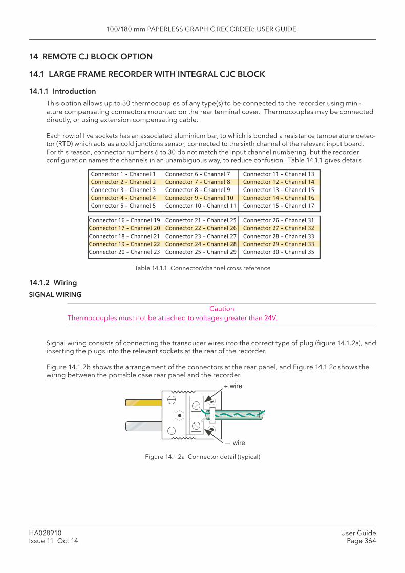
100/180 mm PAPERLESS GRAPHIC RECORDER: USER GUIDE
HA028910Issue 11 Oct 14
User GuidePage 364
14 REMOTE CJ BLOCK OPTION
14.1 LARGE FRAME RECORDER WITH INTEGRAL CJC BLOCK
14.1.1 Introduction
This option allows up to 30 thermocouples of any type(s) to be connected to the recorder using mini-ature compensating connectors mounted on the rear terminal cover. Thermocouples may be connected directly, or using extension compensating cable.
Each row of fi ve sockets has an associated aluminium bar, to which is bonded a resistance temperature detec-tor (RTD) which acts as a cold junctions sensor, connected to the sixth channel of the relevant input board. For this reason, connector numbers 6 to 30 do not match the input channel numbering, but the recorder confi guration names the channels in an unambiguous way, to reduce confusion. Table 14.1.1 gives details.
Table 14.1.1 Connector/channel cross reference
14.1.2 Wiring
SIGNAL WIRING
CautionThermocouples must not be attached to voltages greater than 24V,
Signal wiring consists of connecting the transducer wires into the correct type of plug (fi gure 14.1.2a), and inserting the plugs into the relevant sockets at the rear of the recorder.
Figure 14.1.2b shows the arrangement of the connectors at the rear panel, and Figure 14.1.2c shows the wiring between the portable case rear panel and the recorder.
Connector 1 - Channel 1
Connector 2 - Channel 2
Connector 3 - Channel 3
Connector 4 - Channel 4
Connector 5 - Channel 5
Connector 6 - Channel 7
Connector 7 - Channel 8
Connector 8 - Channel 9
Connector 9 - Channel 10
Connector 10 - Channel 11
Connector 11 - Channel 13
Connector 12 - Channel 14
Connector 13 - Channel 15
Connector 14 - Channel 16
Connector 15 - Channel 17
Connector 16 - Channel 19
Connector 17 - Channel 20
Connector 18 - Channel 21
Connector 19 - Channel 22
Connector 20 - Channel 23
Connector 21 - Channel 25
Connector 22 - Channel 26
Connector 23 - Channel 27
Connector 24 - Channel 28
Connector 25 - Channel 29
Connector 26 - Channel 31
Connector 27 - Channel 32
Connector 28 - Channel 33
Connector 29 - Channel 33
Connector 30 - Channel 35
Figure 14.1.2a Connector detail (typical)
+ wire
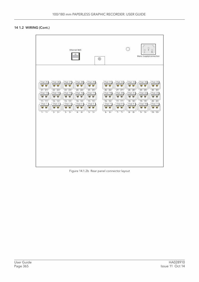
100/180 mm PAPERLESS GRAPHIC RECORDER: USER GUIDE
HA028910Issue 11 Oct 14
User GuidePage 365
14 1.2 WIRING (Cont.)
Figure 14.1.2b Rear panel connector layout
Ethernet RJ45
L N
E
Mains (supply)connection
1- 1+
Chan 1 Chan 2 Chan 3 Chan 4 Chan 5
Chan 13 Chan 14 Chan 15 Chan 16 Chan 17
Chan 25 Chan 26 Chan 27 Chan 28 Chan 29
11- 11+
21- 21+
2- 2+
12- 12+
22- 22+
3- 3+
13- 13+
23- 23+
4- 4+
14- 14+
24- 24+
5- 5+
15- 15+
25- 25+
6- 6+
Chan 7 Chan 8 Chan 9 Chan 10 Chan 11
Chan 19 Chan 20 Chan 21 Chan 22 Chan 23
Chan 31 Chan 32 Chan 33 Chan 34 Chan 35
16- 16+
26- 26+
7- 7+
17- 17+
27- 27+
8- 8+
18- 18+
28- 28+
9- 9+
19- 19+
29- 29+
10- 10+
20- 20+
30- 30+

100/180 mm PAPERLESS GRAPHIC RECORDER: USER GUIDE
HA028910Issue 11 Oct 14
User GuidePage 366
14 1.2 WIRING (Cont.)
Figure 14.1.2c Internal wiring
14.1.3 Specifi cation
Information additional to the general specifi cation in Annex A.
Measurement accuracy (typical) Static at 25˚C: <±0.2˚C error (after overall system calibration) 0 to 50˚C: <±0.3˚C error (after overall system calibration)Start-up time at ambient 2 minutesIsolation <30V RMS or <60Vdc
Input board 2
1
2
3
4
5
6
7
8
9
10
11
12
13
14
15
16
17
18
19
20
21
22
Input board 1V+
V-
I
V+
V-
I
V+
V-
I
V+
V-
I
V+
V-
I
V+
V-
I
CJ sensor
1+
1-
2+
2-
3+
3-
4+
4-
5+
5-
Ch1
Ch2
Ch3
Ch4
Ch5
Ch6
Brown
Black
Red
Black
Orange
Black
Yellow
Black
Green
Black
Blue
Blue
Violet
Violet
Power supply unitBrown
Blue
Green/Yellow
L
N
E
Line supply �
(100 to 240V)
(50/60 Hz)
EarthChassis ground
(Safety earth)
Recorder back panel
Terminal cover
L
N
E
Ethernet
connector
RTD mounted �
on connector blocks
(six places)
1
2
3
4
5
6
7
8
9
10
11
12
13
14
15
16
17
18
19
20
21
22
V+
V-
I
V+
V-
I
V+
V-
I
V+
V-
I
V+
V-
I
V+
V-
I
CJ sensor
6+
6-
7+
7-
8+
8-
9+
9-
10+
10-
Ch7
Ch8
Ch9
Ch10
Ch11
Ch12
Brown
Black
Red
Black
Orange
Black
Yellow
Black
Green
Black
Blue
Blue
Violet
Violet
Input board 31
2
3
4
5
6
7
8
9
10
11
12
13
14
15
16
17
18
19
20
21
22
V+
V-
I
V+
V-
I
V+
V-
I
V+
V-
I
V+
V-
I
V+
V-
I
CJ sensor
11+
11-
12+
12-
13+
13-
14+
14-
15+
15-
Ch13
Ch14
Ch15
Ch16
Ch17
Ch18
Brown
Black
Red
Black
Orange
Black
Yellow
Black
Green
Black
Blue
Blue
Violet
Violet
V+
V-
I
V+
V-
I
V+
V-
I
V+
V-
I
V+
V-
I
V+
V-
I
1
2
3
4
5
6
7
8
9
10
11
12
13
14
15
16
17
18
19
20
21
22
CJ sensor
Brown
Black
Red
Black
Orange
Black
Yellow
Black
Green
Black
Blue
Blue
Violet
Violet
Input board 4 16+
16-
17+
17-
18+
18-
19+
19-
20+
20-
V+
V-
I
V+
V-
I
V+
V-
I
V+
V-
I
V+
V-
1
2
3
4
5
6
7
8
9
10
11
12
13
14
15
16
17
CJ sensor
Brown
Black
Red
Black
Orange
Black
Yellow
Black
Green
Black
Input board 5 21+
22-
23+
23-
24+
24-
25+
25-
26+
26-I
V+
V-
I
18
19
20
21
22
Blue
Blue
Violet
Violet
V+
V-
I
V+
V-
I
V+
V-
I
V+
V-
I
V+
V-
1
2
3
4
5
6
7
8
9
10
11
12
13
14
15
16
17
CJ sensor
Brown
Black
Red
Black
Orange
Black
Yellow
Black
Green
Black
Input board 6 26+
26-
27+
27-
28+
28-
29+
29-
30+
30-I
V+
V-
I
18
19
20
21
22
Blue
Blue
Violet
Violet
Ch19
Ch20
Ch21
Ch22
Ch23
Ch24
Ch25
Ch26
Ch27
Ch28
Ch29
Ch30
Ch31
Ch32
Ch33
Ch34
Ch35
Ch36
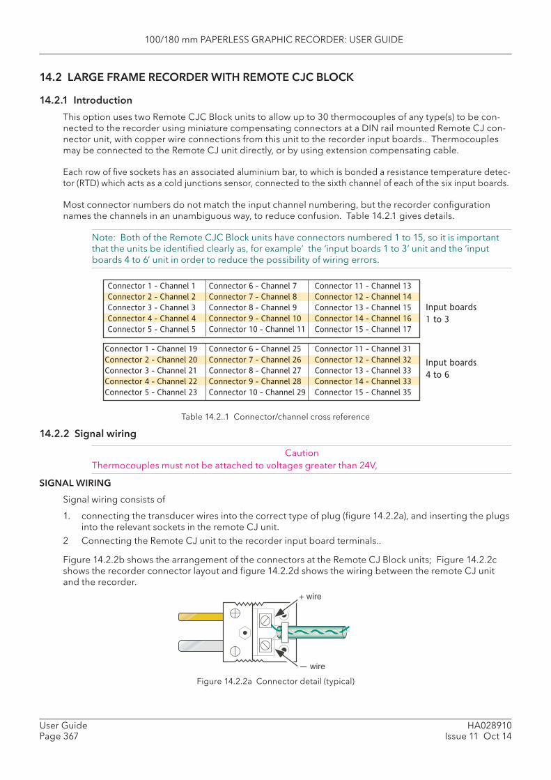
100/180 mm PAPERLESS GRAPHIC RECORDER: USER GUIDE
HA028910Issue 11 Oct 14
User GuidePage 367
14.2 LARGE FRAME RECORDER WITH REMOTE CJC BLOCK
14.2.1 Introduction
This option uses two Remote CJC Block units to allow up to 30 thermocouples of any type(s) to be con-nected to the recorder using miniature compensating connectors at a DIN rail mounted Remote CJ con-nector unit, with copper wire connections from this unit to the recorder input boards.. Thermocouples may be connected to the Remote CJ unit directly, or by using extension compensating cable.
Each row of fi ve sockets has an associated aluminium bar, to which is bonded a resistance temperature detec-tor (RTD) which acts as a cold junctions sensor, connected to the sixth channel of each of the six input boards.
Most connector numbers do not match the input channel numbering, but the recorder confi guration names the channels in an unambiguous way, to reduce confusion. Table 14.2.1 gives details.
Note: Both of the Remote CJC Block units have connectors numbered 1 to 15, so it is important that the units be identifi ed clearly as, for example’ the ‘input boards 1 to 3’ unit and the ‘input boards 4 to 6’ unit in order to reduce the possibility of wiring errors.
Table 14.2..1 Connector/channel cross reference
14.2.2 Signal wiring
CautionThermocouples must not be attached to voltages greater than 24V,
SIGNAL WIRING
Signal wiring consists of
1. connecting the transducer wires into the correct type of plug (fi gure 14.2.2a), and inserting the plugs into the relevant sockets in the remote CJ unit.
2 Connecting the Remote CJ unit to the recorder input board terminals..
Figure 14.2.2b shows the arrangement of the connectors at the Remote CJ Block units; Figure 14.2.2c shows the recorder connector layout and fi gure 14.2.2d shows the wiring between the remote CJ unit and the recorder.
Figure 14.2.2a Connector detail (typical)
Connector 1 - Channel 1
Connector 2 - Channel 2
Connector 3 - Channel 3
Connector 4 - Channel 4
Connector 5 - Channel 5
Connector 6 - Channel 7
Connector 7 - Channel 8
Connector 8 - Channel 9
Connector 9 - Channel 10
Connector 10 - Channel 11
Connector 11 - Channel 13
Connector 12 - Channel 14
Connector 13 - Channel 15
Connector 14 - Channel 16
Connector 15 - Channel 17
Connector 1 - Channel 19
Connector 2 - Channel 20
Connector 3 - Channel 21
Connector 4 - Channel 22
Connector 5 - Channel 23
Connector 6 - Channel 25
Connector 7 - Channel 26
Connector 8 - Channel 27
Connector 9 - Channel 28
Connector 10 - Channel 29
Connector 11 - Channel 31
Connector 12 - Channel 32
Connector 13 - Channel 33
Connector 14 - Channel 33
Connector 15 - Channel 35
Input boards
1 to 3
Input boards
4 to 6
+ wire
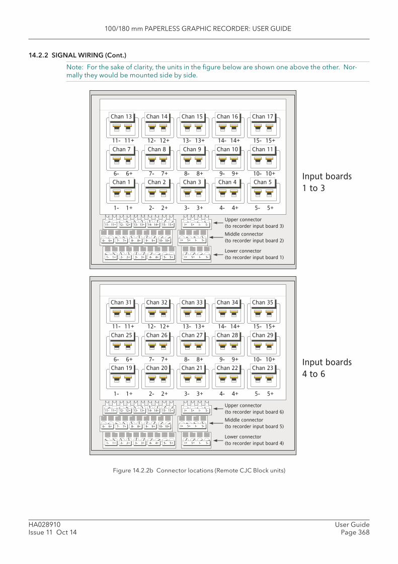
100/180 mm PAPERLESS GRAPHIC RECORDER: USER GUIDE
HA028910Issue 11 Oct 14
User GuidePage 368
14.2.2 SIGNAL WIRING (Cont.)
Note: For the sake of clarity, the units in the fi gure below are shown one above the other. Nor-mally they would be mounted side by side.
Figure 14.2.2b Connector locations (Remote CJC Block units)
1- 1+
Chan 1 Chan 2 Chan 3 Chan 4 Chan 5
Chan 7 Chan 8 Chan 9 Chan 10 Chan 11
Chan 13 Chan 14 Chan 15 Chan 16 Chan 17
6- 6+
11- 11+
2- 2+
7- 7+
12- 12+
3- 3+
8- 8+
13- 13+
4- 4+
9- 9+
14- 14+
5- 5+
10- 10+
15- 15+
15- 15+14- 14+13- 13+12- 12+11- 11+
10- 10+9- 9+8- 8+7- 7+6- 6+
5- 5+4- 4+3- 3+2- 2+1- 1+
I+ S+ I- S-
I+ S+ I- S-
I+ S+ I- S-
Upper connector �
(to recorder input board 3)
Middle connector �
(to recorder input board 2)
Lower connector �
(to recorder input board 1)
Input boards
1 to 3
1- 1+
Chan 19 Chan 20 Chan 21 Chan 22 Chan 23
Chan 25 Chan 26 Chan 27 Chan 28 Chan 29
Chan 31 Chan 32 Chan 33 Chan 34 Chan 35
6- 6+
11- 11+
2- 2+
7- 7+
12- 12+
3- 3+
8- 8+
13- 13+
4- 4+
9- 9+
14- 14+
5- 5+
10- 10+
15- 15+
15- 15+14- 14+13- 13+12- 12+11- 11+
10- 10+9- 9+8- 8+7- 7+6- 6+
5- 5+4- 4+3- 3+2- 2+1- 1+
I+ S+ I- S-
I+ S+ I- S-
I+ S+ I- S-
Upper connector �
(to recorder input board 6)
Middle connector �
(to recorder input board 5)
Lower connector �
(to recorder input board 4)
Input boards
4 to 6

100/180 mm PAPERLESS GRAPHIC RECORDER: USER GUIDE
HA028910Issue 11 Oct 14
User GuidePage 369
14.2.2 SIGNAL WIRING (Cont.)
Input board 1
Input board 2
Input board 3
Input board 4
Input board 5
Input board 6
Figure 14.2.2c Connector locations (recorder)
Input channels 1 to 7
Input channels 1 to 6
Input channels 7 to 12
Input channels 1 to 7
Input channels 13 to 18
Input channels 19 to 24
Input channels 1 to 7
Input channels 25 to 30
Input channels 31 to 36
Input channels 1 to 7
Input channels 37 to 42
Input channels 43 to 48
Option board 3 Option board 4
Option board 1 Option board 2
Not used Option board 9
Option board 7 Option board 8
Option board 5 Option board 6
Serial comms (option)
L N
E
Mains (supply)
connection
USB Ports (option)
Ethernet
RJ45
USB1 USB2Port 1 Port 2
Safety Earth
(M4)
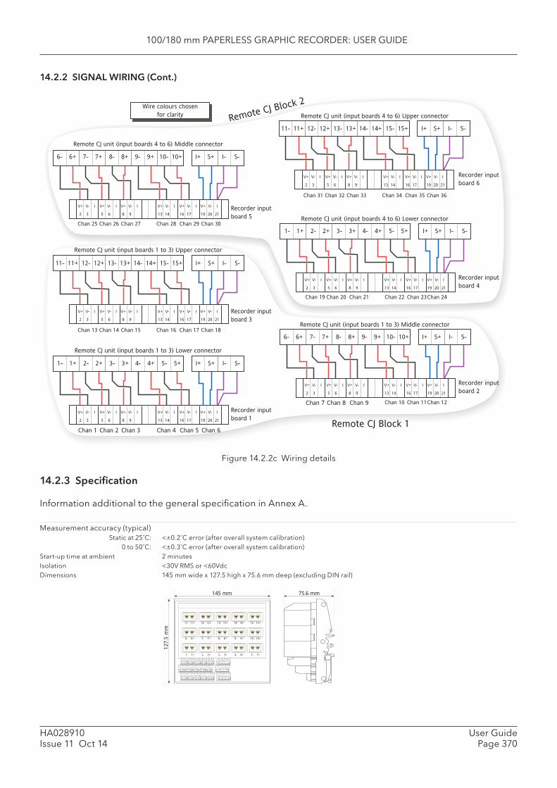
100/180 mm PAPERLESS GRAPHIC RECORDER: USER GUIDE
HA028910Issue 11 Oct 14
User GuidePage 370
14.2.2 SIGNAL WIRING (Cont.)
Figure 14.2.2c Wiring details
14.2.3 Specifi cation
Information additional to the general specifi cation in Annex A.
Measurement accuracy (typical) Static at 25˚C: <±0.2˚C error (after overall system calibration) 0 to 50˚C: <±0.3˚C error (after overall system calibration)Start-up time at ambient 2 minutesIsolation <30V RMS or <60VdcDimensions 145 mm wide x 127.5 high x 75.6 mm deep (excluding DIN rail)
Chan 13 Chan 14 Chan 15 Chan 16 Chan 17 Chan 18
V+ V- I V+ V- I V+ V- I V+ V- I V+ V- I V+ V- I
2 3 5 6 8 9 13 14 16 17 19 20 21
11- 11+ 12- 12+ 13- 13+ 14- 14+ 15- 15+ I+ S+ I- S-
Recorder input �
board 3
Remote CJ unit (input boards 1 to 3) Upper connector
V+ V- I V+ V- I V+ V- I V+ V- I V+ V- I V+ V- I
2 3 5 6 8 9 13 14 16 17 19 20 21
Chan 1 Chan 2 Chan 3 Chan 4 Chan 5 Chan 6
Recorder input �
board 1
I+ S+ I- S-1- 1+ 2- 2+ 3- 3+ 4- 4+ 5- 5+
Remote CJ unit (input boards 1 to 3) Lower connector
Chan 7 Chan 8 Chan 9 Chan 10 Chan 11Chan 12
V+ V- I V+ V- I V+ V- I V+ V- I V+ V- I V+ V- I
2 3 5 6 8 9 13 14 16 17 19 20 21
6- 6+ 7- 7+ 8- 8+ 9- 9+ 10- 10+ I+ S+ I- S-
Recorder input �
board 2
Remote CJ unit (input boards 1 to 3) Middle connector
Wire colours chosen �
for clarity
V+ V- I V+ V- I V+ V- I V+ V- I V+ V- I V+ V- I
2 3 5 6 8 9 13 14 16 17 19 20 21
Chan 25 Chan 26 Chan 27 Chan 28 Chan 29 Chan 30
Recorder input �
board 5
Remote CJ unit (input boards 4 to 6) Middle connector
6- 6+ 7- 7+ 8- 8+ 9- 9+ 10- 10+ I+ S+ I- S-
Chan 19 Chan 20 Chan 21 Chan 22 Chan 23Chan 24
V+ V- I V+ V- I V+ V- I V+ V- I V+ V- I V+ V- I
2 3 5 6 8 9 13 14 16 17 19 20 21
Recorder input �
board 4
I+ S+ I- S-1- 1+ 2- 2+ 3- 3+ 4- 4+ 5- 5+
Remote CJ unit (input boards 4 to 6) Lower connector
Chan 31 Chan 32 Chan 33 Chan 34 Chan 35 Chan 36
V+ V- I V+ V- I V+ V- I V+ V- I V+ V- I V+ V- I
2 3 5 6 8 9 13 14 16 17 19 20 21
11- 11+ 12- 12+ 13- 13+ 14- 14+ 15- 15+ I+ S+ I- S-
Remote CJ unit (input boards 4 to 6) Upper connector
Recorder input �
board 6
Remote CJ Block 1
Remote CJ Block 2
75.6 mm
1- 1+
6- 6+
11- 11+
2- 2+
7- 7+
12- 12+
3- 3+
8- 8+
13- 13+
4- 4+
9- 9+
14- 14+
5- 5+
10- 10+
15- 15+
15- 15+14- 14+13- 13+12- 12+11- 11+
10- 10+9- 9+8- 8+7- 7+6- 6+
5- 5+4- 4+3- 3+2- 2+1- 1+
I+ S+ I- S-
I+ S+ I- S-
I+ S+ I- S-
145 mm
127.5
mm
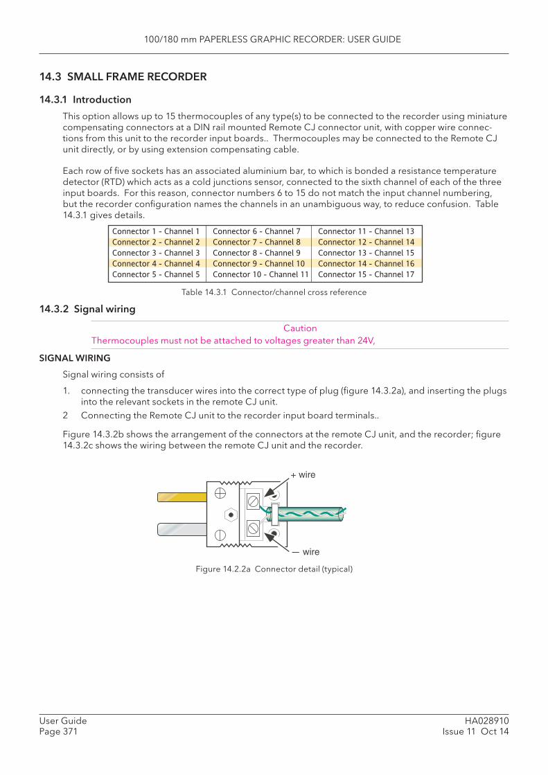
100/180 mm PAPERLESS GRAPHIC RECORDER: USER GUIDE
HA028910Issue 11 Oct 14
User GuidePage 371
14.3 SMALL FRAME RECORDER
14.3.1 Introduction
This option allows up to 15 thermocouples of any type(s) to be connected to the recorder using miniature compensating connectors at a DIN rail mounted Remote CJ connector unit, with copper wire connec-tions from this unit to the recorder input boards.. Thermocouples may be connected to the Remote CJ unit directly, or by using extension compensating cable.
Each row of fi ve sockets has an associated aluminium bar, to which is bonded a resistance temperature detector (RTD) which acts as a cold junctions sensor, connected to the sixth channel of each of the three input boards. For this reason, connector numbers 6 to 15 do not match the input channel numbering, but the recorder confi guration names the channels in an unambiguous way, to reduce confusion. Table 14.3.1 gives details.
Table 14.3.1 Connector/channel cross reference
14.3.2 Signal wiring
CautionThermocouples must not be attached to voltages greater than 24V,
SIGNAL WIRING
Signal wiring consists of
1. connecting the transducer wires into the correct type of plug (fi gure 14.3.2a), and inserting the plugs into the relevant sockets in the remote CJ unit.
2 Connecting the Remote CJ unit to the recorder input board terminals..
Figure 14.3.2b shows the arrangement of the connectors at the remote CJ unit, and the recorder; fi gure 14.3.2c shows the wiring between the remote CJ unit and the recorder.
Connector 1 - Channel 1
Connector 2 - Channel 2
Connector 3 - Channel 3
Connector 4 - Channel 4
Connector 5 - Channel 5
Connector 6 - Channel 7
Connector 7 - Channel 8
Connector 8 - Channel 9
Connector 9 - Channel 10
Connector 10 - Channel 11
Connector 11 - Channel 13
Connector 12 - Channel 14
Connector 13 - Channel 15
Connector 14 - Channel 16
Connector 15 - Channel 17
Figure 14.2.2a Connector detail (typical)
+ wire
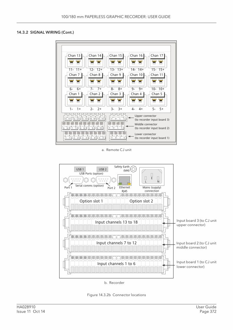
100/180 mm PAPERLESS GRAPHIC RECORDER: USER GUIDE
HA028910Issue 11 Oct 14
User GuidePage 372
14.3.2 SIGNAL WIRING (Cont.)
Figure 14.3.2b Connector locations
1- 1+
Chan 1 Chan 2 Chan 3 Chan 4 Chan 5
Chan 7 Chan 8 Chan 9 Chan 10 Chan 11
Chan 13 Chan 14 Chan 15 Chan 16 Chan 17
6- 6+
11- 11+
2- 2+
7- 7+
12- 12+
3- 3+
8- 8+
13- 13+
4- 4+
9- 9+
14- 14+
5- 5+
10- 10+
15- 15+
15- 15+14- 14+13- 13+12- 12+11- 11+
10- 10+9- 9+8- 8+7- 7+6- 6+
5- 5+4- 4+3- 3+2- 2+1- 1+
I+ S+ I- S-
I+ S+ I- S-
I+ S+ I- S-
Upper connector �
(to recorder input board 3)
Middle connector �
(to recorder input board 2)
Lower connector �
(to recorder input board 1)
L N
E
Mains (supply)
connection
Input channels 1 to 6
Option slot 1 Option slot 2
Input channels 7 to 12
Input channels 13 to 18
Serial comms (option)
USB Ports (option)
USB 1 USB 2
Port 1 Port 2 Ethernet
RJ45
Safety Earth
(M4)
b. Recorder
a. Remote CJ unit
Input board 3 (to CJ unit upper connector)
Input board 2 (to CJ unit middle connector)
Input board 1 (to CJ unit lower connector)
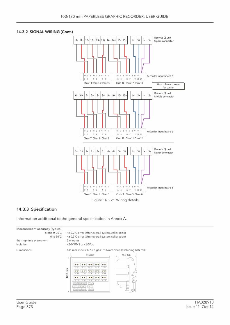
100/180 mm PAPERLESS GRAPHIC RECORDER: USER GUIDE
HA028910Issue 11 Oct 14
User GuidePage 373
14.3.2 SIGNAL WIRING (Cont.)
Figure 14.3.2c Wiring details
14.3.3 Specifi cation
Information additional to the general specifi cation in Annex A.
Measurement accuracy (typical) Static at 25˚C: <±0.2˚C error (after overall system calibration) 0 to 50˚C: <±0.3˚C error (after overall system calibration)Start-up time at ambient 2 minutesIsolation <30V RMS or <60Vdc
Dimensions 145 mm wide x 127.5 high x 75.6 mm deep (excluding DIN rail)
11- 11+ 12- 12+ 13- 13+ 14- 14+ 15- 15+ I+ S+ I- S-
V+ V- I V+ V- I V+ V- I V+ V- I V+ V- I V+ V- I
Chan 13 Chan 14 Chan 15 Chan 16 Chan 17 Chan 18
2 3 5 6 8 9 13 14 16 17 19 20 21
Recorder input board 3
Remote CJ unit
Upper connector
6- 6+ 7- 7+ 8- 8+ 9- 9+ 10- 10+ I+ S+ I- S-
V+ V- I V+ V- I V+ V- I V+ V- I V+ V- I V+ V- I
Chan 7 Chan 8 Chan 9 Chan 10 Chan 11 Chan 12
2 3 5 6 8 9 13 14 16 17 19 20 21
Recorder input board 2
Remote CJ unit
Middle connector
1- 1+ 2- 2+ 3- 3+ 4- 4+ 5- 5+ I+ S+ I- S-
V+ V- I V+ V- I V+ V- I V+ V- I V+ V- I V+ V- I
Chan 1 Chan 2 Chan 3 Chan 4 Chan 5 Chan 6
2 3 5 6 8 9 13 14 16 17 19 20 21
Recorder input board 1
Remote CJ unit
Lower connector
Wire colours chosen �
for clarity
75.6 mm
1- 1+
6- 6+
11- 11+
2- 2+
7- 7+
12- 12+
3- 3+
8- 8+
13- 13+
4- 4+
9- 9+
14- 14+
5- 5+
10- 10+
15- 15+
15- 15+14- 14+13- 13+12- 12+11- 11+
10- 10+9- 9+8- 8+7- 7+6- 6+
5- 5+4- 4+3- 3+2- 2+1- 1+
I+ S+ I- S-
I+ S+ I- S-
I+ S+ I- S-
145 mm
127.5
mm
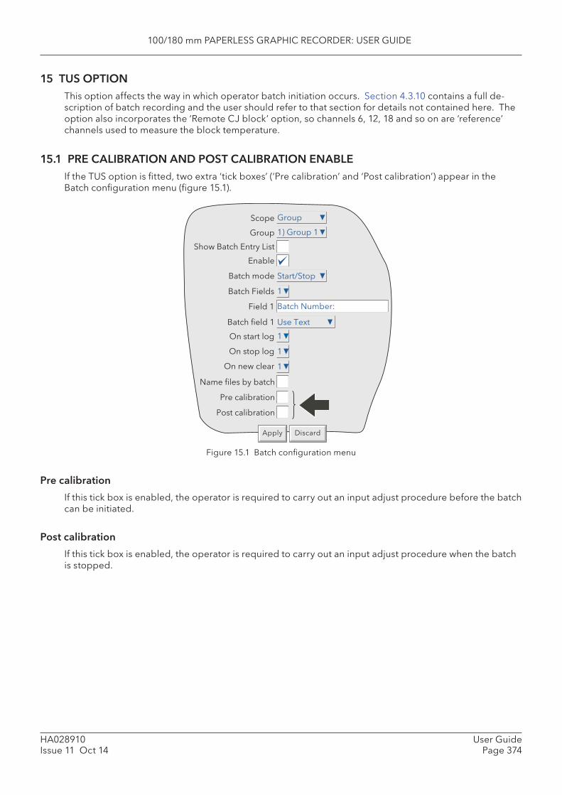
100/180 mm PAPERLESS GRAPHIC RECORDER: USER GUIDE
HA028910Issue 11 Oct 14
User GuidePage 374
15 TUS OPTION This option affects the way in which operator batch initiation occurs. Section 4.3.10 contains a full de-scription of batch recording and the user should refer to that section for details not contained here. The option also incorporates the ‘Remote CJ block’ option, so channels 6, 12, 18 and so on are ‘reference’ channels used to measure the block temperature.
15.1 PRE CALIBRATION AND POST CALIBRATION ENABLEIf the TUS option is fi tted, two extra ‘tick boxes’ (‘Pre calibration’ and ‘Post calibration’) appear in the Batch confi guration menu (fi gure 15.1).
Figure 15.1 Batch confi guration menu
Pre calibration
If this tick box is enabled, the operator is required to carry out an input adjust procedure before the batch can be initiated.
Post calibration
If this tick box is enabled, the operator is required to carry out an input adjust procedure when the batch is stopped.
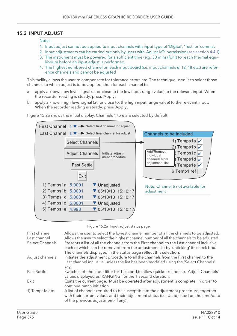
100/180 mm PAPERLESS GRAPHIC RECORDER: USER GUIDE
HA028910Issue 11 Oct 14
User GuidePage 375
15.2 INPUT ADJUSTNotes1. Input adjust cannot be applied to input channels with input type of ‘Digital’, ‘Test’ or ‘comms’.2. Input adjustments can be carried out only by users with ‘Adjust I/O’ permission (see section 4.4.1).3. The instrument must be powered for a suffi cient time (e.g. 30 mins) for it to reach thermal equi-
librium before an input adjust is performed.4. The highest numbered channel on each input board (i.e. input channels 6, 12, 18 etc.) are refer-
ence channels and cannot be adjusted
This facility allows the user to compensate for tolerance errors etc. The technique used is to select those channels to which adjust is to be applied, then for each channel to:
a apply a known low level signal (at or close to the low input range value) to the relevant input. When the recorder reading is steady, press ‘Apply’.
b. apply a known high level signal (at, or close to, the high input range value) to the relevant input. When the recorder reading is steady, press ‘Apply’.
Figure 15.2a shows the initial display. Channels 1 to 6 are selected by default.
Figure 15.2a Input adjust status page
First channel Allows the user to select the lowest channel number of all the channels to be adjusted. Last channel Allows the user to select the highest channel number of all the channels to be adjusted. Select Channels Presents a list of all the channels from the First channel to the Last channel inclusive,
each of which can be removed from the adjustment list by ‘unticking’ its check box. The channels displayed in the status page refl ect this selection.
Adjust channels Initiates the adjustment procedure to all the channels from the First channel to the Last channel inclusive, unless the list has been modifi ed using the ‘Select Channels’ key.
Fast Settle Switches off the input fi lter for 1 second,to allow quicker response. Adjust Channels’ values displayed as ‘RANGING’ for the 1 second duration.
Exit Quits the current page. Must be operated after adjustment is complete, in order to continue batch initiation.
1) Temps1a etc. A list of channels required to be susceptible to the adjustment procedure, together with their current values and their adjustment status (i.e. Unadjusted or, the time/date of the previous adjustment (if any)).
����������� �������
� ��������� � ������ �����������������
���������� � ������ ������������������
�� ��������������������
���������
�� �� ����!��!�"
�� �� ����!��!�"
���������
�� �� ����!��!�"
�#����
�#����
�#����
�#����
$#%%&
'������������
�������������
�������
()
�*+������
,*+������
-*+������
$*+������
�*+������
�*+������
,*+������
-*+������
$*+������
�*+������
�+�������
'�� .���/� �� / ������������������������� �
Note: Channel 6 not available for adjustment
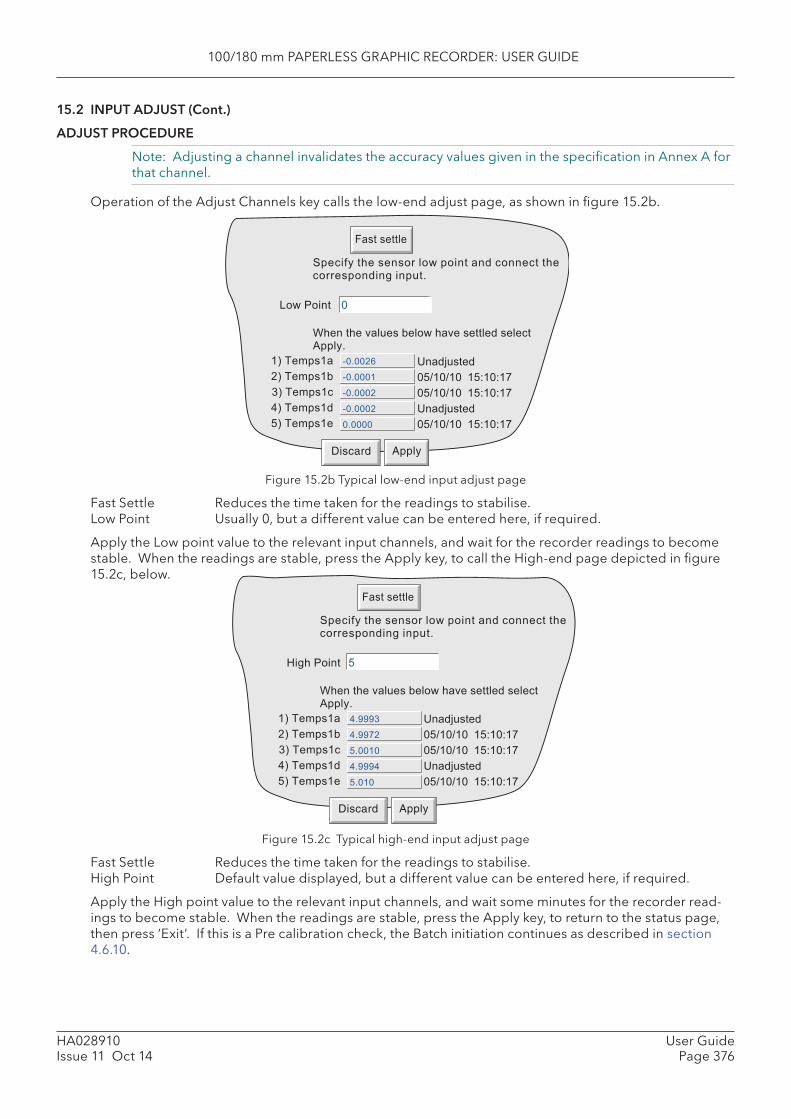
100/180 mm PAPERLESS GRAPHIC RECORDER: USER GUIDE
HA028910Issue 11 Oct 14
User GuidePage 376
15.2 INPUT ADJUST (Cont.)
ADJUST PROCEDURE
Note: Adjusting a channel invalidates the accuracy values given in the specifi cation in Annex A for that channel.
Operation of the Adjust Channels key calls the low-end adjust page, as shown in fi gure 15.2b.
Figure 15.2b Typical low-end input adjust page
Fast Settle Reduces the time taken for the readings to stabilise. Low Point Usually 0, but a different value can be entered here, if required.
Apply the Low point value to the relevant input channels, and wait for the recorder readings to become stable. When the readings are stable, press the Apply key, to call the High-end page depicted in fi gure 15.2c, below.
Figure 15.2c Typical high-end input adjust page
Fast Settle Reduces the time taken for the readings to stabilise. High Point Default value displayed, but a different value can be entered here, if required.
Apply the High point value to the relevant input channels, and wait some minutes for the recorder read-ings to become stable. When the readings are stable, press the Apply key, to return to the status page, then press ‘Exit’. If this is a Pre calibration check, the Batch initiation continues as described in section 4.6.10.
���� �0����������1�� ���������������������� �2 ���#
��#���,
��#���,
��#����
��#��,�
�#����
��13� � �
4�����/���������1��/�����������'���0#
�������
�*+������
,*+������
-*+������
$*+������
�*+������
ApplyDiscard
���������
�� �� ����!��!�"
�� �� ����!��!�"
���������
�� �� ����!��!�"
���� �0����������1�� ���������������������� �2 ���#
$#%%%$
�#����
$#%%",
$#%%%-
�#���
5 2�3� � �
4�����/���������1��/�����������'���0#
�������
�*+������
,*+������
-*+������
$*+������
�*+������
ApplyDiscard
���������
�� �� ����!��!�"
�� �� ����!��!�"
���������
�� �� ����!��!�"

100/180 mm PAPERLESS GRAPHIC RECORDER: USER GUIDE
HA028910Issue 11 Oct 14
User GuidePage 377
15.3 CHART MESSAGESIf Audit Trail is enabled then a number of messages appear on the chart, and included in the history fi le as described in section 4.4.2. If the TUS option is enabled, ‘Pre calibration’ and/or ‘Post calibration tick boxes are ticked, then further messages are produced for each adjusted channel, showing the pre cali-bration and post calibration high and low values.
Example:
05/10/10 16:20:57 5) Temps1e Pre cal high 5.010 Post cal high 5.00005/10/10 16:20:57 4) Temps1d Pre cal high 4.994 Post cal high 5.00005/10/10 16:20:57 3) Temps1c Pre cal high 5.001 Post cal high 5.00005/10/10 16:20:57 2) Temps1b Pre cal high 4.997 Post cal high 5.00005/10/10 16:20:57 1) Temps1a Pre cal high 4.993 Post cal high 5.00005/10/10 16:20:57 5) Temps1e Pre cal low 0.000 Post cal low 0.00005/10/10 16:20:57 4) Temps1e Pre cal low -0.002 Post cal low 0.00005/10/10 16:20:57 3) Temps1e Pre cal low -0.002 Post cal low 0.00005/10/10 16:20:57 2) Temps1e Pre cal low 0.001 Post cal low 0.00005/10/10 16:20:57 1) Temps1e Pre cal low -0.003 Post cal low 0.000
15.4 OTHER ITEMSInput channels 6, 12, 18 etc. are reference channels used to measure the temperature of the remote CJ block. They are therefore excluded from the adjust procedure and channel offsets (section 4.3.3) cannot be applied to them.
In ‘Save and Restore’, channel confi guration will not be restored.
Batch initiation must be by operator action - job triggered batches do not support pre and post calibra-tion.

100/180 mm PAPERLESS GRAPHIC RECORDER: USER GUIDE
User GuidePage 378
HA028910Issue 11 Oct 14
ANNEX A: SPECIFICATION
INSTALLATION CATEGORY AND POLLUTION DEGREEThis product has been designed to conform to BS EN61010 installation category II and pollution degree 2. These are defi ned as follows:
Installation category II
The rated impulse voltage for equipment on nominal 230V ac mains is 2500V.
Pollution degree 2
Normally, only non-conductive pollution occurs. Occasionally, however, a temporary conductivity caused by condensation shall be expected.
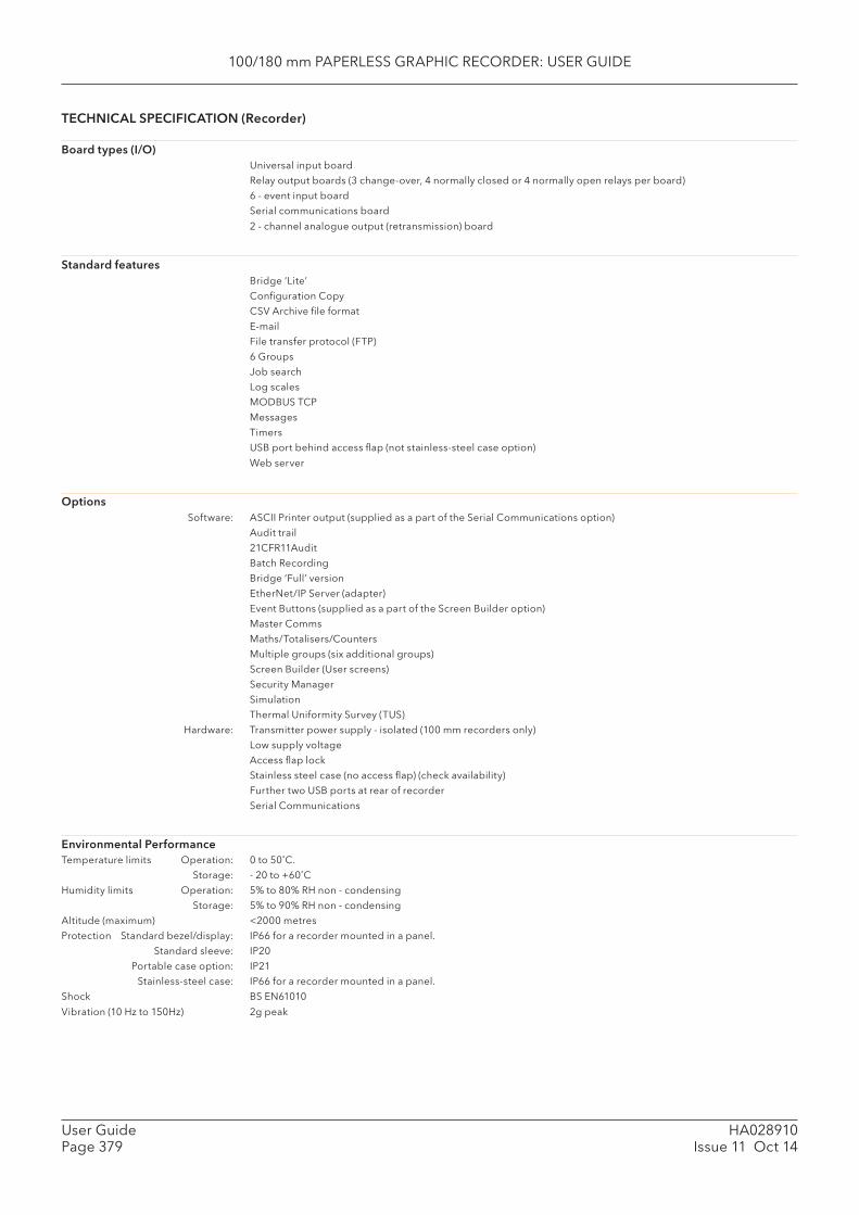
100/180 mm PAPERLESS GRAPHIC RECORDER: USER GUIDE
HA028910Issue 11 Oct 14
User GuidePage 379
TECHNICAL SPECIFICATION (Recorder)
Board types (I/O) Universal input board
Relay output boards (3 change-over, 4 normally closed or 4 normally open relays per board)
6 - event input board
Serial communications board
2 - channel analogue output (retransmission) board
Standard features Bridge ‘Lite’
Confi guration Copy
CSV Archive fi le format
File transfer protocol (FTP)
6 Groups
Job search
Log scales
MODBUS TCP
Messages
Timers
USB port behind access fl ap (not stainless-steel case option)
Web server
Options Software: ASCII Printer output (supplied as a part of the Serial Communications option)
Audit trail
21CFR11Audit
Batch Recording
Bridge ‘Full’ version
EtherNet/IP Server (adapter)
Event Buttons (supplied as a part of the Screen Builder option)
Master Comms
Maths/Totalisers/Counters
Multiple groups (six additional groups)
Screen Builder (User screens)
Security Manager
Simulation
Thermal Uniformity Survey (TUS)
Hardware: Transmitter power supply - isolated (100 mm recorders only)
Low supply voltage
Access fl ap lock
Stainless steel case (no access fl ap) (check availability)
Further two USB ports at rear of recorder
Serial Communications
Environmental PerformanceTemperature limits Operation: 0 to 50˚C.
Storage: - 20 to +60˚C
Humidity limits Operation: 5% to 80% RH non - condensing
Storage: 5% to 90% RH non - condensing
Altitude (maximum) <2000 metres
Protection Standard bezel/display: IP66 for a recorder mounted in a panel.
Standard sleeve: IP20
Portable case option: IP21
Stainless-steel case: IP66 for a recorder mounted in a panel.
Shock BS EN61010
Vibration (10 Hz to 150Hz) 2g peak
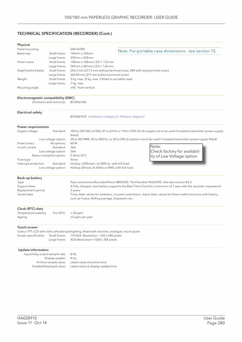
100/180 mm PAPERLESS GRAPHIC RECORDER: USER GUIDE
User GuidePage 380
HA028910Issue 11 Oct 14
TECHNICAL SPECIFICATION (RECORDER) (Cont.)
PhysicalPanel mounting DIN 43700
Bezel size Small frame: 144mm x 144mm
Large frame: 292mm x 292mm
Panel cutout Small frame: 138mm x 138mm (-0.0 + 1.0) mm
Large frame; 281mm x 281mm (-0.0 + 1.0) mm
Depth behind bezel Small frame: 246.5 mm (211.5 mm without terminal cover, 284 with long terminal cover)
Large frame: 260.90 mm (211 mm without terminal cover)
Weight Small frame: 3 kg. max. (5 kg. max. if fi tted in portable case)
Large frame: 7 kg. max.
Mounting angle ±45 ˚ from vertical
Electromagnetic compatibility (EMC) Emissions and immunity: BS EN61326
Electrical safety BS EN61010. Installation category II, Pollution degree 2
Power requirements Supply voltage Standard: 100 to 230 VAC (±15%); 47 to 63 Hz or 110 to 370V dc (dc supply not to be used if isolated transmitter power supply
fi tted) Low voltage option: 20 to 42V RMS; 45 to 400 Hz, or 20 to 54V dc (option not to be used if isolated transmitter power supply fi tted)Power (max.) All options: 60 WInrush current Standard: 36A Low voltage option: 36A Namur compliant option: 5.5A at 25˚CFuse type NoneInterrupt protection Standard: Holdup >200msec. at 240V ac, with full load. Low voltage option: Holdup 20msec at 20Vdc or RMS, with full load.
Back-up batteryType Poly-carbonmonofl uoride/lithium (BR2330). Part Number PA261095. See also section B2.2.Support time A fully-charged, new battery supports the Real-Time Clock for a minimum of 1 year with the recorder unpoweredReplacement period 3-years Stored data Time; date; values for totalisers, counters and timers; batch data; values for those maths functions with history,
such as Fvalue, Rolling average, Stopwatch etc.
Clock (RTC) dataTemperature stability 0 to 50˚C: ± 20 ppmAgeing ±5 ppm per year
Touch screenColour TFT LCD with cold-cathode backlighting, fi tted with resistive, analogue, touch panelScreen specifi cation Small frame: 1/4 VGA Resolution = 320 x 240 pixels Large frame: XGA Resolution= 1024 x 768 pixels
Update information Input/relay output sample rate: 8 Hz. Display update: 8 Hz, Archive sample value: Latest value at archive time Trended/displayed value: Latest value at display update time
Note: For portable case dimensions - see section 13.
Note:Check factory for availabil-ity of Low Voltage option

100/180 mm PAPERLESS GRAPHIC RECORDER: USER GUIDE
HA028910Issue 11 Oct 14
User GuidePage 381
TECHNICAL SPECIFICATION (RECORDER) (Cont.)
Ethernet CommunicationsType 10/100 base T (IEEE802.3)Protocols TCP/IP, FTP, DHCP, BootP, SNTP, Modbus, SMTP, ICMP.Cable Type: CAT5 Maximum length: 100 metres Termination: RJ45 RJ45 LED indicators Green: Indicates a 100MB link Yellow: Indicates Ethernet activityInternal green LED Indicates a 10MB link
Serial communications optionNumber of ports Two, at rear of instrumentProtocol ASCII input, ASCII printer, Modbus master, Modbus slave.Transmission standards EIA232 and/or EIA485, software selectable per port. EIA485 can be connected as 3-wire or 5-wire as required.Isolation (dc to 65Hz BS EN61010) Installation category II; Pollution degree 2. Terminals to ground: 50 V RMS or dc (basic insulation)
Transmitter power supply (Isolated) (Small frame recorders only ) Number of outputs ThreeOutput voltage 25V nominalMax. current 20mA per outputIsolation (dc to 65Hz BS EN61010) Installation category II; Pollution degree 2. Channel to channel: 100V RMS or dc (double insulation) Channel to ground: 100V RMS or dc (basic insulation).Fuse (20mm Type T) Supply voltage = 110/120Vac: 100 mA Supply voltage = 220/240Vac: 63 mA
USB portsNumber of ports 1 at front of recorder (standard*); 2 further ports (optional - at rear of instrument)
(*No front USB port with Stainless steel case option)Standard USB1.1Transmission speeds 12Mbits/sec (full speed devices) or 1.5Mbits/sec (low speed devices)Maximum current per port 500mAPeripherals supported Floppy disk drive, Keyboard, Bar code reader, Mouse, Memory stick.
Note: The recorder meets the industrial EMC requirements of BS EN61326. Typically, USB pe-ripherals are tested to domestic information technology standards (BS EN55022) with category C performance. Some USB peripherals, designed for use in domestic or offi ce environments, can be susceptible to ‘lock up’ in environments containing high electromagnetic fi eld strengths. In order to recover from such ‘lock up’ situations, the peripheral must be disconnected and then recon-nected. Recorder operation is not affected.
Other items
Virus susceptibility The 6000 series VxWorks operating system is immune to viruses targeted at Windows based operating systems. As at December 2005, there are no known viruses that target VxWorks.
Calibration coeffi cients Input: The Read-only input coeffi cients are stored in EEPROM on the input board. Instrument: Instrument confi guration is held in FLASH memory and has no effect on calibration coeffi cients.
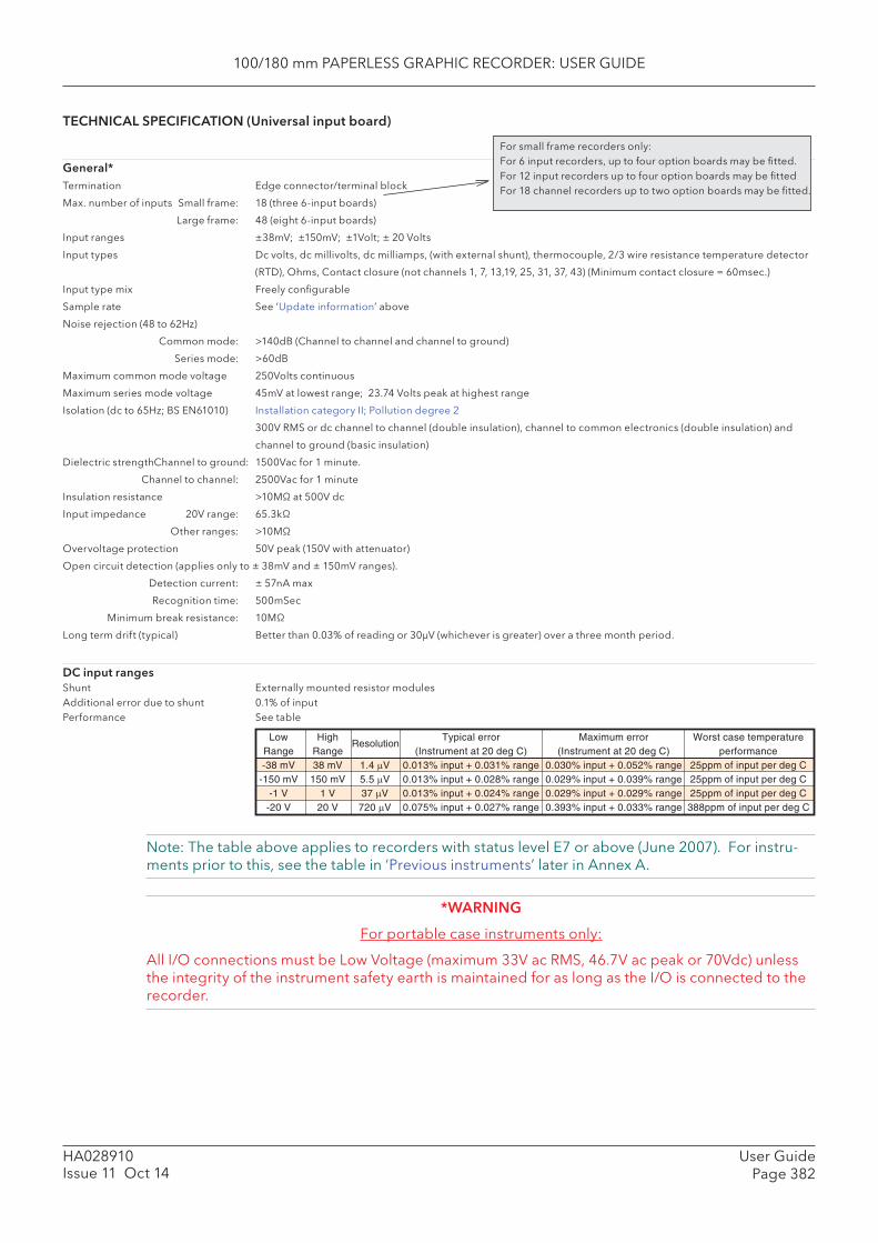
100/180 mm PAPERLESS GRAPHIC RECORDER: USER GUIDE
User GuidePage 382
HA028910Issue 11 Oct 14
TECHNICAL SPECIFICATION (Universal input board)
General*Termination Edge connector/terminal block
Max. number of inputs Small frame: 18 (three 6-input boards)
Large frame: 48 (eight 6-input boards)
Input ranges ±38mV; ±150mV; ±1Volt; ± 20 Volts
Input types Dc volts, dc millivolts, dc milliamps, (with external shunt), thermocouple, 2/3 wire resistance temperature detector
(RTD), Ohms, Contact closure (not channels 1, 7, 13,19, 25, 31, 37, 43) (Minimum contact closure = 60msec.)
Input type mix Freely confi gurable
Sample rate See ‘Update information’ above
Noise rejection (48 to 62Hz)
Common mode: >140dB (Channel to channel and channel to ground)
Series mode: >60dB
Maximum common mode voltage 250Volts continuous
Maximum series mode voltage 45mV at lowest range; 23.74 Volts peak at highest range
Isolation (dc to 65Hz; BS EN61010) Installation category II; Pollution degree 2
300V RMS or dc channel to channel (double insulation), channel to common electronics (double insulation) and
channel to ground (basic insulation)
Dielectric strength Channel to ground: 1500Vac for 1 minute.
Channel to channel: 2500Vac for 1 minute
Insulation resistance >10MΩ at 500V dc
Input impedance 20V range: 65.3kΩ
Other ranges: >10MΩ
Overvoltage protection 50V peak (150V with attenuator)
Open circuit detection (applies only to ± 38mV and ± 150mV ranges).
Detection current: ± 57nA max
Recognition time: 500mSec
Minimum break resistance: 10MΩ
Long term drift (typical) Better than 0.03% of reading or 30μV (whichever is greater) over a three month period.
DC input ranges Shunt Externally mounted resistor modulesAdditional error due to shunt 0.1% of inputPerformance See table
Note: The table above applies to recorders with status level E7 or above (June 2007). For instru-ments prior to this, see the table in ‘Previous instruments’ later in Annex A.
*WARNING
For portable case instruments only:
All I/O connections must be Low Voltage (maximum 33V ac RMS, 46.7V ac peak or 70Vdc) unless the integrity of the instrument safety earth is maintained for as long as the I/O is connected to the recorder.
For small frame recorders only:For 6 input recorders, up to four option boards may be fi tted. For 12 input recorders up to four option boards may be fi ttedFor 18 channel recorders up to two option boards may be fi tted.
Low High Typical error Maximum error Worst case temperatureRange Range (Instrument at 20 deg C) (Instrument at 20 deg C) performance-38 mV 38 mV 1.4 μV 0.013% input + 0.031% range 0.030% input + 0.052% range 25ppm of input per deg C
-150 mV 150 mV 5.5 μV 0.013% input + 0.028% range 0.029% input + 0.039% range 25ppm of input per deg C-1 V 1 V 37 μV 0.013% input + 0.024% range 0.029% input + 0.029% range 25ppm of input per deg C
-20 V 20 V 720 μV 0.075% input + 0.027% range 0.393% input + 0.033% range 388ppm of input per deg C
Resolution
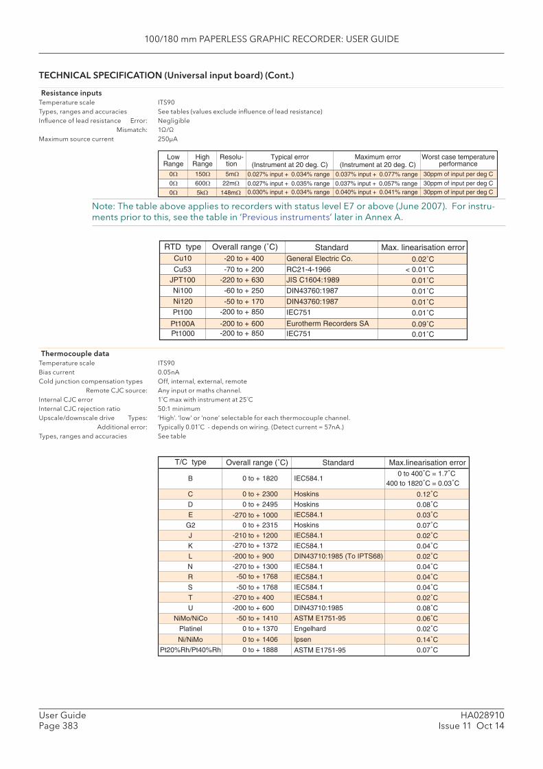
100/180 mm PAPERLESS GRAPHIC RECORDER: USER GUIDE
HA028910Issue 11 Oct 14
User GuidePage 383
TECHNICAL SPECIFICATION (Universal input board) (Cont.)
Resistance inputs Temperature scale ITS90Types, ranges and accuracies See tables (values exclude infl uence of lead resistance)Infl uence of lead resistance Error: Negligible Mismatch: 1Ω/ΩMaximum source current 250μA
0.14˚C0.07˚C
0 to 400˚C = 1.7˚CMax.linearisation error
0.12˚C0.08˚C0.03˚C0.07˚C0.02˚C0.04˚C
0.04˚C0.04˚C0.02˚C0.08˚C0.06˚C0.02˚C
400 to 1820˚C = 0.03˚C
0.02˚C0.04˚C
Ni/NiMo
Pt20%Rh/Pt40%Rh
T/C type
B
C
D
E
G2
J
K
R
S
T
U
NiMo/NiCo
Platinel
L
N
0 to + 1406
0 to + 1888
0 to + 1820
0 to + 2300
0 to + 2495
-270 to + 10000 to + 2315
-210 to + 1200-270 to + 1372
-50 to + 1768
-50 to + 1768
-270 to + 400
-200 to + 600
-50 to + 1410
0 to + 1370
-200 to + 900
-270 to + 1300
Overall range (˚C)
Ipsen
ASTM E1751-95
IEC584.1
Standard
Hoskins
Hoskins
IEC584.1
Hoskins
IEC584.1
IEC584.1
IEC584.1
IEC584.1
IEC584.1
DIN43710:1985
ASTM E1751-95
Engelhard
DIN43710:1985 (To IPTS68)
IEC584.1
RTD typeCu10
JPT100Ni100
Ni120
Overall range (˚C) Standard0.02˚C
0.01˚C
0.01˚C
0.01˚C
0.01˚C
0.09˚C0.01˚C
Pt100
Pt100APt1000
-20 to + 400
-220 to + 630
-60 to + 250
-50 to + 170-200 to + 850
-200 to + 600-200 to + 850
General Electric Co.
JIS C1604:1989
DIN43760:1987
DIN43760:1987
IEC751
Eurotherm Recorders SAIEC751
Max. linearisation error
Cu53 < 0.01˚C-70 to + 200 RC21-4-1966
Note: The table above applies to recorders with status level E7 or above (June 2007). For instru-ments prior to this, see the table in ‘Previous instruments’ later in Annex A.
LowRange
0Ω0Ω0Ω
HighRange
150Ω600Ω5kΩ
Resolu-tion
5mΩ22mΩ
148mΩ
Typical error(Instrument at 20 deg. C)
0.027% input + 0.034% range 30ppm of input per deg C
30ppm of input per deg C30ppm of input per deg C
0.027% input + 0.035% range0.030% input + 0.034% range
Worst case temperatureperformance
Maximum error(Instrument at 20 deg. C)
0.037% input + 0.077% range
0.037% input + 0.057% range0.040% input + 0.041% range
Thermocouple dataTemperature scale ITS90Bias current 0.05nACold junction compensation types Off, internal, external, remote Remote CJC source: Any input or maths channel.Internal CJC error 1˚C max with instrument at 25˚CInternal CJC rejection ratio 50:1 minimumUpscale/downscale drive Types: ‘High’. ‘low’ or ‘none’ selectable for each thermocouple channel. Additional error: Typically 0.01˚C - depends on wiring. (Detect current = 57nA.)Types, ranges and accuracies See table

100/180 mm PAPERLESS GRAPHIC RECORDER: USER GUIDE
User GuidePage 384
HA028910Issue 11 Oct 14
WORST CASE ERROR CALCULATION
Assuming type T thermocouple at 350˚C, ambient temp = 40˚C, CJC = internal.
Total error = input error + range error + temperature error +linearisation error + cold junction error.
Input error:
From thermocouple tables, a type T thermocouple generates a voltage of 17.819mV at 350 ˚C. From the dc performance table above, the maximum error is 0.030% input = 0.03 x 17.819/100 = 5.346μV
Range error:
The 38mV range is used as the type t thermocouple is defi ned to cover the range -270˚C (-6.258mV) to +400˚C (20.872mV). From the dc performance table, the maximum range error is 0.052% range, and the range is 38 + 38 = 76 mV. Thus the maximum range error is 0.052 x 76/100 = 39.52μV.
Temperature error:
The dc performance table above is specifed at 20˚C, but the ambient in this example is 40˚C. From the dc performance table, the worst case temperature performance is 25ppm/˚C, so our error is 25 x (40-20) x 17.819 x 10-6 = 8.910μV.
Linearisation error:
From the thermocouple table, the maximum linearisation error for a type t thermocouple is 0.02 ˚C
Cold junction compensation (CJC) error:
The internal CJC error is 1˚C maximum with the instrument at 25˚C. The CJC rejection ratio is 50:1, so a further error of (40-25)/50 = 0.30 ˚C may occur, giving a total maximum CJC error of 1.3˚C.
Maximum errorFrom the above, the total error adds up as follows:Input error: 5.346μVRange error: 39.520μVTemperature error: 8.910μVLinearisation error: 0.02˚CCJC error: 1.30 ˚CTotal error: 53.776μV + 1.32˚C
From thermocouple tables, a change of 1˚C is equivalent to a change of 60μV, so a change of 53.776μV is equivalent to a change of 0.896˚C.
Thus the total worst case error for this example is (0.896 + 1.32) = 2.216˚C
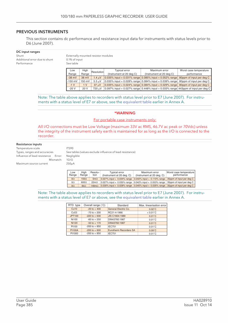
100/180 mm PAPERLESS GRAPHIC RECORDER: USER GUIDE
HA028910Issue 11 Oct 14
User GuidePage 385
PREVIOUS INSTRUMENTS
This section contains dc performance and resistance input data for instruments with status levels prior to D6 (June 2007).
DC input rangesShunt Externally mounted resistor modulesAdditional error due to shunt 0.1% of inputPerformance See table
Low High Typical error Maximum error Worst case temperatureRange Range (Instrument at 20 deg C) (Instrument at 20 deg C) performance-38 mV 38 mV 1.4 μV 0.035% input + 0.031% range 0.085% input + 0.052% range 80ppm of input per deg C
-150 mV 150 mV 5.5 μV 0.035% input + 0.028% range 0.084% input + 0.039% range 80ppm of input per deg C-1 V 1 V 37 μV 0.035% input + 0.024% range 0.084% input + 0.029% range 80ppm of input per deg C
-20 V 20 V 720 μV 0.097% input + 0.027% range 0.448% input + 0.033% range 443ppm of input per deg C
Resolution
Note: The table above applies to recorders with status level prior to E7 (June 2007). For instru-ments with a status level of E7 or above, see the equivalent table earlier in Annex A.
*WARNING
For portable case instruments only:
All I/O connections must be Low Voltage (maximum 33V ac RMS, 46.7V ac peak or 70Vdc) unless the integrity of the instrument safety earth is maintained for as long as the I/O is connected to the recorder.
Resistance inputsTemperature scale ITS90Types, ranges and accuracies See tables (values exclude infl uence of lead resistance)Infl uence of lead resistance Error: Negligible Mismatch: 1Ω/ΩMaximum source current 250μA
LowRange
0Ω0Ω0Ω
HighRange
150Ω600Ω6kΩ
Resolu-tion
5mΩ22mΩ
148mΩ
Typical error(Instrument at 20 deg. C)
0.027% input + 0.034% range 35ppm of input per deg C
35ppm of input per deg C35ppm of input per deg C
0.027% input + 0.035% range0.030% input + 0.028% range
Worst case temperatureperformance
Maximum error(Instrument at 20 deg. C)
0.042% input + 0.110% range
0.042% input + 0.053% range0.045% input + 0.035% range
Note: The table above applies to recorders with status level prior to E7 (June 2007). For instru-ments with a status level of E7 or above, see the equivalent table earlier in Annex A.
RTD typeCu10
JPT100Ni100
Ni120
Overall range (˚C) Standard0.02˚C
0.01˚C
0.01˚C
0.01˚C
0.01˚C
0.09˚C0.01˚C
Pt100
Pt100APt1000
-20 to + 400
-220 to + 630
-60 to + 250
-50 to + 170-200 to + 850
-200 to + 600-200 to + 850
General Electric Co.
JIS C1604:1989
DIN43760:1987
DIN43760:1987
IEC751
Eurotherm Recorders SAIEC751
Max. linearisation error
Cu53 < 0.01˚C-70 to + 200 RC21-4-1966
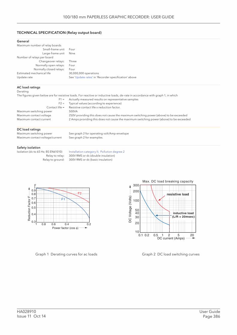
100/180 mm PAPERLESS GRAPHIC RECORDER: USER GUIDE
User GuidePage 386
HA028910Issue 11 Oct 14
TECHNICAL SPECIFICATION (Relay output board)
GeneralMaximum number of relay boards Small-frame unit Four Large-frame unit NineNumber of relays per board Changeover relays: Three Normally open relays: Four Normally closed relays: FourEstimated mechanical life 30,000,000 operationsUpdate rate See ‘Update rates’ in ‘Recorder specifi cation’ above
AC load ratingsDeratingThe fi gures given below are for resistive loads. For reactive or inductive loads, de-rate in accordance with graph 1, in which F1 = Actually measured results on representative samples F2 = Typical values (according to experience) Contact life = Resistive contact life x reduction factor. Maximum switching power 500VAMaximum contact voltage 250V providing this does not cause the maximum switching power (above) to be exceededMaximum contact current 2 Amps providing this does not cause the maximum switching power (above) to be exceeded
DC load ratingsMaximum switching power See graph 2 for operating volt/Amp envelopeMaximum contact voltage/current See graph 2 for examples.
Safety isolationIsolation (dc to 65 Hz; BS EN61010) Installation category II; Pollution degree 2 Relay to relay: 300V RMS or dc (double insulation) Relay to ground: 300V RMS or dc (basic insulation)
F1
F2
1 0.8 0.6 0.4 0.20.3
0.4
0.5
0.6
0.7
0.80.9
1F
Red
uctio
n F
acto
r F
Power factor (cos φ)
Graph 1 Derating curves for ac loads Graph 2 DC load switching curves
10
20
304050
100
200
300
0.1 0.2 0.5 5 20
Max. DC load breaking capacity
1 2
inductive load(L/R = 20msec)
resistive load
DC
Vol
tage
(V
olts
)
DC current (Amps)
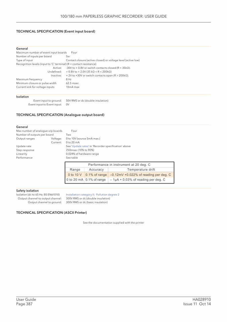
100/180 mm PAPERLESS GRAPHIC RECORDER: USER GUIDE
HA028910Issue 11 Oct 14
User GuidePage 387
TECHNICAL SPECIFICATION (Event input board)
GeneralMaximum number of event input boards FourNumber of inputs per board Six Type of input Contact closure (active closed) or voltage level (active low)Recognition levels (input to ‘C’ terminal) (R = contact resistance) Active: -30V to + 0.8V or switch contacts closed (R < 35kΩ). Undefi ned: + 0.8V to + 2.0V (35 kΩ < R < 200kΩ) Inactive: + 2V to +30V or switch contacts open (R > 200kΩ).Maximum frequency 8 HzMinimum closure or pulse width 62.5 msecCurrent sink for voltage inputs 10mA max
Isolation Event input to ground: 50V RMS or dc (double insulation) Event input to Event input: 0V
TECHNICAL SPECIFICATION (Analogue output board)
GeneralMax number of analogue o/p boards FourNumber of outputs per board TwoOutput ranges Voltage: 0 to 10V (source 5mA max.) Current: 0 to 20 mAUpdate rate See ‘Update rates’ in ‘Recorder specifi cation’ aboveStep response 250msec (10% to 90%)Linearity 0.024% of hardware rangePerformance See table
0 to 10 V0 to 20 mA
0.1% of range0.1% of range
–0.12mV +0.022% of reading per deg. C– 1µA + 0.03% of reading per deg. C
Range Accuracy Temperature driftPerformance in instrument at 20 deg. C
Safety isolationIsolation (dc to 65 Hz; BS EN61010) Installation category II; Pollution degree 2 Output channel-to output channel: 300V RMS or dc (double insulation) Output channel to ground: 300V RMS or dc (basic insulation)
TECHNICAL SPECIFICATION (ASCII Printer)
See the documentation supplied with the printer

100/180 mm PAPERLESS GRAPHIC RECORDER: USER GUIDE
User GuidePage 388
HA028910Issue 11 Oct 14
ANNEX B: REFERENCE
B1 DIAGNOSTICS DISPLAY
B1.1 MAIN DIAGNOSTIC DISPLAYAt power-up, continuously hold a fi nger in contact with the screen until the main diagnostic display ap-pears as shown in fi gure B1.1
Special Modes Display Test
Touch Calibration System Summary
Diag Summary Quit
Figure B1.1 Top-level diagnostic display

100/180 mm PAPERLESS GRAPHIC RECORDER: USER GUIDE
HA028910Issue 11 Oct 14
User GuidePage 389
B1.2 S PECIAL MODESFor factory use only, selecting 'Special Modes' allows the enabling and disabling of the Sales Demo mode of operation.
An 'S' symbol is displayed at the top of the screen whilst the recorder is in sales demo mode.
B1.3 DISPLAY TESTSelecting this option, allows the user to check the display by fl ooding the screen with single colours. Repeatedly touching the screen, scrolls through the following colour sequence: Black, White, Red, Green, Blue, Cyan, Magenta, Yellow. A further operation of the touch screen returns the main diagnostic screen.
B1.4 TOUCH CALIBRATIONTouching this key calls a selection screen as shown below:
Figure B1.4 Touch screen selections
Touch Screen Calibrate
Touch Screen Verify
Main Menu
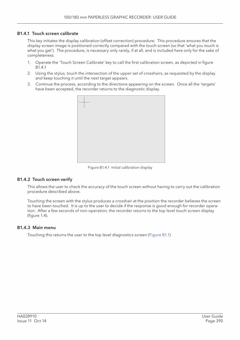
100/180 mm PAPERLESS GRAPHIC RECORDER: USER GUIDE
User GuidePage 390
HA028910Issue 11 Oct 14
B1.4.1 Touch screen calibrate
This key initiates the display calibration (offset correction) procedure. This procedure ensures that the display screen image is positioned correctly compared with the touch screen (so that 'what you touch is what you get'). The procedure, is necessary only rarely, if at all, and is included here only for the sake of completeness.
1. Operate the 'Touch Screen Calibrate' key to call the fi rst calibration screen, as depicted in fi gure B1.4.1
2. Using the stylus, touch the intersection of the upper set of crosshairs, as requested by the display and keep touching it until the next target appears.
3. Continue the process, according to the directions appearing on the screen. Once all the 'targets' have been accepted, the recorder returns to the diagnostic display.
Figure B1.4.1 Initial calibration display
B1.4.2 Touch screen verify
This allows the user to check the accuracy of the touch screen without having to carry out the calibration procedure described above.
Touching the screen with the stylus produces a crosshair at the position the recorder believes the screen to have been touched. It is up to the user to decide if the response is good enough for recorder opera-tion. After a few seconds of non-operation, the recorder returns to the top level touch screen display (fi gure 1.4).
B1.4.3 Main menu
Touching this returns the user to the top level diagnostics screen (Figure B1.1)
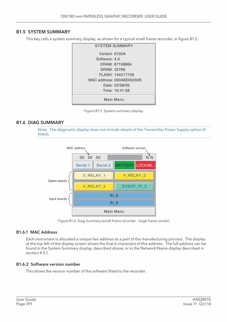
100/180 mm PAPERLESS GRAPHIC RECORDER: USER GUIDE
HA028910Issue 11 Oct 14
User GuidePage 391
B1.5 SYSTEM SUMMARY This key calls a system summary display, as shown for a typical small-frame recorder, in fi gure B1.5.
Figure B1.5 System summary display
B1.6 DIAG SUMMARYNote: The diagnostic display does not include details of the Transmitter Power Supply option (if fi tted).
Main Menu
SYSTEM SUMMARY
Variant: 6100ASoftware: 4.0
DRAM: 67108864SRAM: 32768
FLASH: 134217728MAC address: 000A8D002026
Date: 02/08/05Time: 16:41:58
3_RELAY_1 4_RELAY_2
Main Menu
4_RELAY_3
AI_6
AI_6
BATTERY LOCKAB...
00 00 00
Serial 2
N.N
Serial 1
MAC address
Option boards
Input boards
Software version
EVENT_IP_3
Figure B1.6 Diag Summary (small frame recorder - large frame similar)
B1.6.1 MAC Address
Each instrument is allocated a unique hex address as a part of the manufacturing process. The display at the top left of the display screen shows the fi nal 6 characters of this address. The full address can be found in the System Summary display, described above, or in the Network\Name display described in section 4.5.1.
B1.6.2 Software version number
This shows the version number of the software fi tted to the recorder.
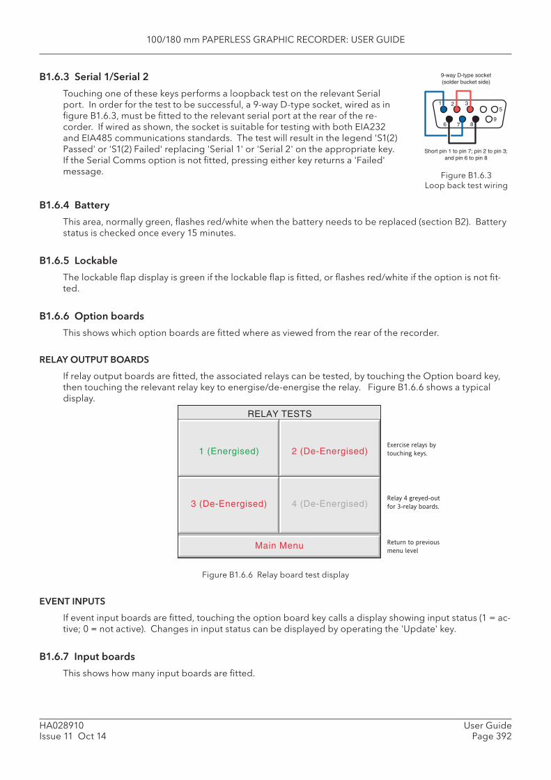
100/180 mm PAPERLESS GRAPHIC RECORDER: USER GUIDE
User GuidePage 392
HA028910Issue 11 Oct 14
B1.6.3 Serial 1/Serial 2
Touching one of these keys performs a loopback test on the relevant Serial port. In order for the test to be successful, a 9-way D-type socket, wired as in fi gure B1.6.3, must be fi tted to the relevant serial port at the rear of the re-corder. If wired as shown, the socket is suitable for testing with both EIA232 and EIA485 communications standards. The test will result in the legend 'S1(2) Passed' or 'S1(2) Failed' replacing 'Serial 1' or 'Serial 2' on the appropriate key. If the Serial Comms option is not fi tted, pressing either key returns a 'Failed' message.
Figure B1.6.6 Relay board test display
EVENT INPUTS
If event input boards are fi tted, touching the option board key calls a display showing input status (1 = ac-tive; 0 = not active). Changes in input status can be displayed by operating the 'Update' key.
B1.6.7 Input boards
This shows how many input boards are fi tted.
Main Menu
RELAY TESTS
1 (Energised) 2 (De-Energised)
3 (De-Energised) 4 (De-Energised)
Exercise relays by
touching keys.
Relay 4 greyed-out
for 3-relay boards.
Return to previous
menu level
Figure B1.6.3 Loop back test wiring
B1.6.4 Battery
This area, normally green, fl ashes red/white when the battery needs to be replaced (section B2). Battery status is checked once every 15 minutes.
B1.6.5 Lockable
The lockable fl ap display is green if the lockable fl ap is fi tted, or fl ashes red/white if the option is not fi t-ted.
B1.6.6 Option boards
This shows which option boards are fi tted where as viewed from the rear of the recorder.
RELAY OUTPUT BOARDS
If relay output boards are fi tted, the associated relays can be tested, by touching the Option board key, then touching the relevant relay key to energise/de-energise the relay. Figure B1.6.6 shows a typical display.
69
2 3
7 8
15
9-way D-type socket(solder bucket side)
Short pin 1 to pin 7; pin 2 to pin 3;and pin 6 to pin 8

100/180 mm PAPERLESS GRAPHIC RECORDER: USER GUIDE
HA028910Issue 11 Oct 14
User GuidePage 393
B1.6.8 Main menu
To return to the main diagnostics display, touch the 'Main Menu' key.
B1.7 QUITAllows the user to quit diagnostics (after confi rmation). The recorder restarts in normal operating mode.
B2 PREVENTIVE MAINTENANCE
B2.1 TOUCH SCREEN CLEANING
CAUTION
The touch-sensitive screen used in this product is designed for use by hand or by the stylus sup-plied only. The use of sharp or pointed implements such as pens, keys and fi ngernails to operate the instrument must be avoided, or irreparable damage will be done to the surface material. When cleaning the touch-screen, a moist cloth should be used, if necessary with a minimal amount of mild soap solution.
ALCOHOLS SUCH AS ISOPROPYL ALCOHOL MUST NEVER BE USED ON THE SCREEN.
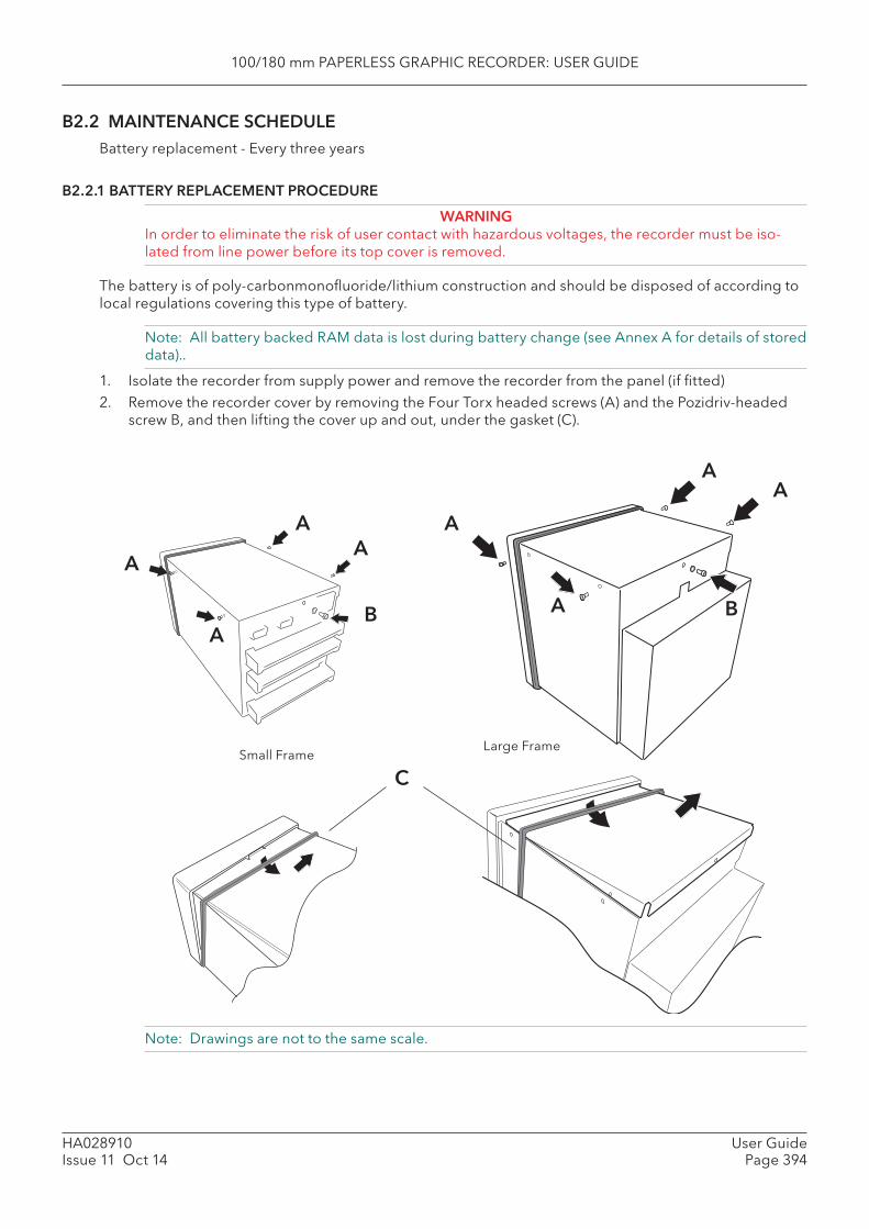
100/180 mm PAPERLESS GRAPHIC RECORDER: USER GUIDE
User GuidePage 394
HA028910Issue 11 Oct 14
A
A
AA
B
CSmall Frame
Large Frame
Note: Drawings are not to the same scale.
B2.2 MAINTENANCE SCHEDULEBattery replacement - Every three years
B2.2.1 BATTERY REPLACEMENT PROCEDURE
WARNINGIn order to eliminate the risk of user contact with hazardous voltages, the recorder must be iso-lated from line power before its top cover is removed.
The battery is of poly-carbonmonofl uoride/lithium construction and should be disposed of according to local regulations covering this type of battery.
Note: All battery backed RAM data is lost during battery change (see Annex A for details of stored data)..
1. Isolate the recorder from supply power and remove the recorder from the panel (if fi tted)2. Remove the recorder cover by removing the Four Torx headed screws (A) and the Pozidriv-headed
screw B, and then lifting the cover up and out, under the gasket (C).
A
A
AA
B
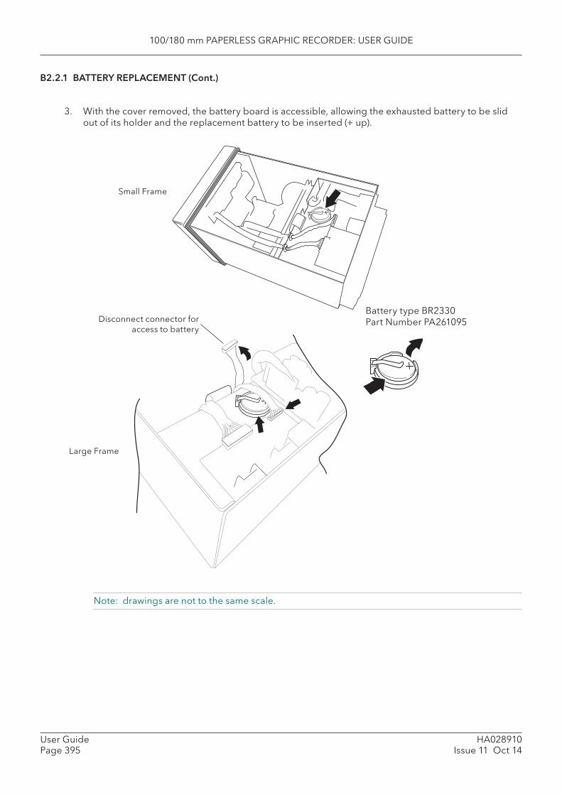
100/180 mm PAPERLESS GRAPHIC RECORDER: USER GUIDE
HA028910Issue 11 Oct 14
User GuidePage 395
B2.2.1 BATTERY REPLACEMENT (Cont.)
3. With the cover removed, the battery board is accessible, allowing the exhausted battery to be slid out of its holder and the replacement battery to be inserted (+ up).
Disconnect connector for access to battery
Small Frame
Large Frame
Battery type BR2330Part Number PA261095
Note: drawings are not to the same scale.

100/180 mm PAPERLESS GRAPHIC RECORDER: USER GUIDE
User GuidePage 396
HA028910Issue 11 Oct 14
B2.3 FLAP RELEASEFor recorders fi tted with the lockable fl ap option (section 2.4), it is possible to unlatch the fl ap from inside the recorder as follows:
1. Remove the recorder cover as described in section B2.2.1, above.
2. Press down on the solenoid actuator to release the fl ap.
Fig 2.3a Flap release - small frame units Fig 2.3b Flap release - large frame units
Note: drawings are not to the same scale.

100/180 mm PAPERLESS GRAPHIC RECORDER: USER GUIDE
HA028910Issue 11 Oct 14
User GuidePage 397
B3 OPTION ENABLING See 'Upgrade' in section 4.6.3.
B4 COLOUR SELECTIONThe following table, gives RGB values and decimal and hex numbers for the available channel colours. Normally, this table is necessary only when communicating over the Modbus link.
Note: Colour representation varies from screen to screen. For this reason, it is unlikely that the colour on a PC will match those on these pages or those on the recorder display.

100/180 mm PAPERLESS GRAPHIC RECORDER: USER GUIDE
User GuidePage 398
HA028910Issue 11 Oct 14
B4 COLOUR SELECTION (Cont.)
Table B4, sheet 1: Colour defi nitions 0 to 27
Colour Red Green Blue Decimal Hex
Red 255 0 0 0 00
Blue 0 0 255 1 01
Green 0 255 0 2 02
Honey 255 191 0 3 03
Violet 170 321 153 4 04
Russet 170 95 0 5 05
Dark Blue 0 0 102 6 06
Jade 0 95 0 7 07
Magenta 255 0 102 8 08
Dusky Rose 255 95 51 9 09
Yellow 255 255 255 10 0A
Powder Blue 85 63 255 11 0B
Dark Red 170 0 0 12 0C
Avocado 0 233 102 13 0D
Indigo 85 0 102 14 0E
Dark Brown 85 63 0 15 0F
Ægean 0 63 51 16 10
Cyan 0 255 255 17 11
Aubergine 85 0 51 18 12
Dark Orange 255 63 0 19 13
Pale Yellow 255 255 51 20 14
Hyacinth 170 0 51 21 15
Dark Green 0 63 0 22 16
Sugar Pink 255 31 204 23 17
Bluebell 85 31 255 24 18
Orange 255 95 0 25 19
Pink 255 159 255 26 1A
Buttermilk 255 255 102 27 1B
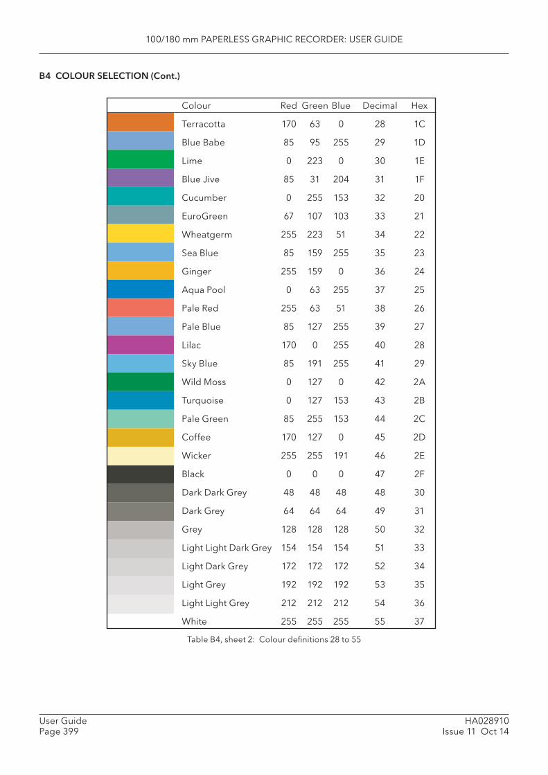
100/180 mm PAPERLESS GRAPHIC RECORDER: USER GUIDE
HA028910Issue 11 Oct 14
User GuidePage 399
B4 COLOUR SELECTION (Cont.)
Table B4, sheet 2: Colour defi nitions 28 to 55
Colour Red Green Blue Decimal Hex
Terracotta 170 63 0 28 1C
Blue Babe 85 95 255 29 1D
Lime 0 223 0 30 1E
Blue Jive 85 31 204 31 1F
Cucumber 0 255 153 32 20
EuroGreen 67 107 103 33 21
Wheatgerm 255 223 51 34 22
Sea Blue 85 159 255 35 23
Ginger 255 159 0 36 24
Aqua Pool 0 63 255 37 25
Pale Red 255 63 51 38 26
Pale Blue 85 127 255 39 27
Lilac 170 0 255 40 28
Sky Blue 85 191 255 41 29
Wild Moss 0 127 0 42 2A
Turquoise 0 127 153 43 2B
Pale Green 85 255 153 44 2C
Coffee 170 127 0 45 2D
Wicker 255 255 191 46 2E
Black 0 0 0 47 2F
Dark Dark Grey 48 48 48 48 30
Dark Grey 64 64 64 49 31
Grey 128 128 128 50 32
Light Light Dark Grey 154 154 154 51 33
Light Dark Grey 172 172 172 52 34
Light Grey 192 192 192 53 35
Light Light Grey 212 212 212 54 36
White 255 255 255 55 37

100/180 mm PAPERLESS GRAPHIC RECORDER: USER GUIDE
User GuidePage 400
HA028910Issue 11 Oct 14
B5 TCP PORT NUMBERSThe following TCP ports are made use of by the recorder. (This information would be needed by anyone involved in setting up 'fi rewalls', which may be used selectively to block incoming or outgoing access to specifi c ports.)
PORT Usage
20 File Transfer Protocol - data
21 File Transfer Protocol - control
25 E-mail; SMTP
80 Web access
123 SNTP server
502 Modbus/TCPIP communications
1264 Bridge communications - general
2222 EtherNet/IP communications
44818 EtherNet/IP communications
50010 Bridge communications - trend review

100/180 mm PAPERLESS GRAPHIC RECORDER: USER GUIDE
HA028910Issue 11 Oct 14
User GuidePage 401
B6 ASCII CHARACTERS FOR SERIAL COMMS This section contains details of the ASCII characters that may be used with the Serial Comms option. All the ASCII characters listed can be used as Start or End-of-message characters, but only characters with decimal codes 32 to 127 can be used in messages, as decimal codes 0 to 31 are replaced by Question marks in messages.
Character Decimal Hex Character Decimal Hex Character Decimal Hex Character Decimal Hex
NUL 0 00 SOH 1 01 STX 2 02 ETX 3 03 EOT 4 04 ENQ 5 05 ACK 6 06 BEL 7 07 BS 8 08 HT 9 09 LF 10 0A VT 11 0B FF 12 0C CR 13 0D SO 14 0E SI 15 0F DLE 16 10 DC1 17 11 DC2 18 12 DC3 19 13 DC4 20 14 NAK 21 15 SYN 22 16 ETB 23 17 CAN 24 18 EM 25 19 SUB 26 1A ESC 27 1B FS 28 1C GS 29 1D RS 30 1E US 31 1F
Space 32 20 ! 33 21 " 34 22 # 35 23 $ 36 24 % 37 25 & 38 26 ’ 39 27 ( 40 28 ) 41 29 * 42 2A + 43 2B , 44 2C - 45 2D . 46 2E / 47 2F 0 48 30 1 49 31 2 50 32 3 51 33 4 52 34 5 53 35 6 54 36 7 55 37 8 56 38 9 57 39 : 58 3A ; 59 3B < 60 3C = 61 3D > 62 3E ? 63 3F
@ 64 40 A 65 41 B 66 42 C 67 43 D 68 44 E 69 45 F 70 46 G 71 47 H 72 48 I 73 49 J 74 4A K 75 4B L 76 4C M 77 4D N 78 4E O 79 4F P 80 50 Q 81 51 R 82 52 S 83 53 T 84 54 U 85 55 V 86 56 W 87 57 X 88 58 Y 89 59 Z 90 5A [ 91 5B \ 92 5C ] 93 5D ^ 94 5E _ 95 5F
‘ 96 60 a 97 61 b 98 62 c 99 63 d 100 64 e 101 65 f 102 66 g 103 67 h 104 68 i 105 69 j 106 6A k 107 6B l 108 6C m 109 6D n 110 6E o 111 6F p 112 70 q 113 71 r 114 72 s 115 73 t 116 74 u 117 75 v 118 76 w 119 77 x 120 78 y 121 79 z 122 7A { 123 7B | 124 7C } 125 7D ~ 126 7E Not printed 127 7F
Notes:
1 All the above characters can be used as Start or End-of-message characters (entered in deci-mal)
2 If characters 0 to 31 ( 00 to 1F) are used as message characters, they will be replaced by ques-tion marks on the screen.
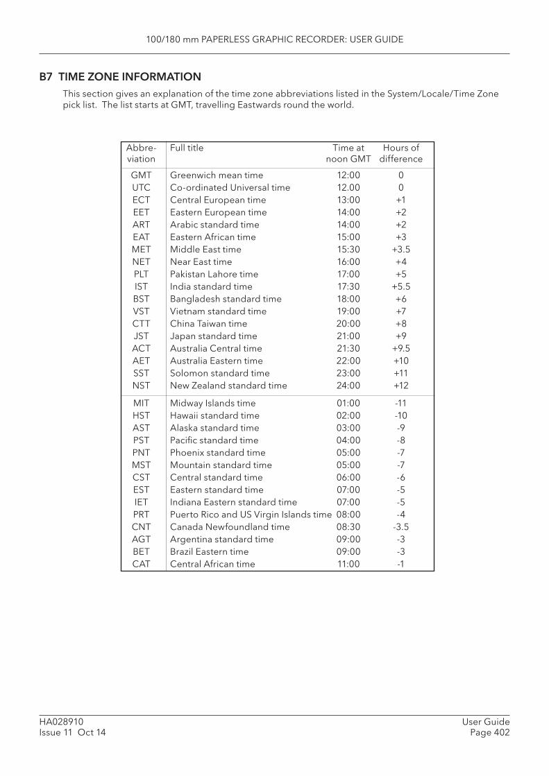
100/180 mm PAPERLESS GRAPHIC RECORDER: USER GUIDE
User GuidePage 402
HA028910Issue 11 Oct 14
B7 TIME ZONE INFORMATIONThis section gives an explanation of the time zone abbreviations listed in the System/Locale/Time Zone pick list. The list starts at GMT, travelling Eastwards round the world.
Abbre- Full title Time at Hours of viation noon GMT difference
GMT Greenwich mean time 12:00 0 UTC Co-ordinated Universal time 12.00 0 ECT Central European time 13:00 +1 EET Eastern European time 14:00 +2 ART Arabic standard time 14:00 +2 EAT Eastern African time 15:00 +3 MET Middle East time 15:30 +3.5 NET Near East time 16:00 +4 PLT Pakistan Lahore time 17:00 +5 IST India standard time 17:30 +5.5 BST Bangladesh standard time 18:00 +6 VST Vietnam standard time 19:00 +7 CTT China Taiwan time 20:00 +8 JST Japan standard time 21:00 +9 ACT Australia Central time 21:30 +9.5 AET Australia Eastern time 22:00 +10 SST Solomon standard time 23:00 +11 NST New Zealand standard time 24:00 +12
MIT Midway Islands time 01:00 -11 HST Hawaii standard time 02:00 -10 AST Alaska standard time 03:00 -9 PST Pacifi c standard time 04:00 -8 PNT Phoenix standard time 05:00 -7 MST Mountain standard time 05:00 -7 CST Central standard time 06:00 -6 EST Eastern standard time 07:00 -5 IET Indiana Eastern standard time 07:00 -5 PRT Puerto Rico and US Virgin Islands time 08:00 -4 CNT Canada Newfoundland time 08:30 -3.5 AGT Argentina standard time 09:00 -3 BET Brazil Eastern time 09:00 -3 CAT Central African time 11:00 -1
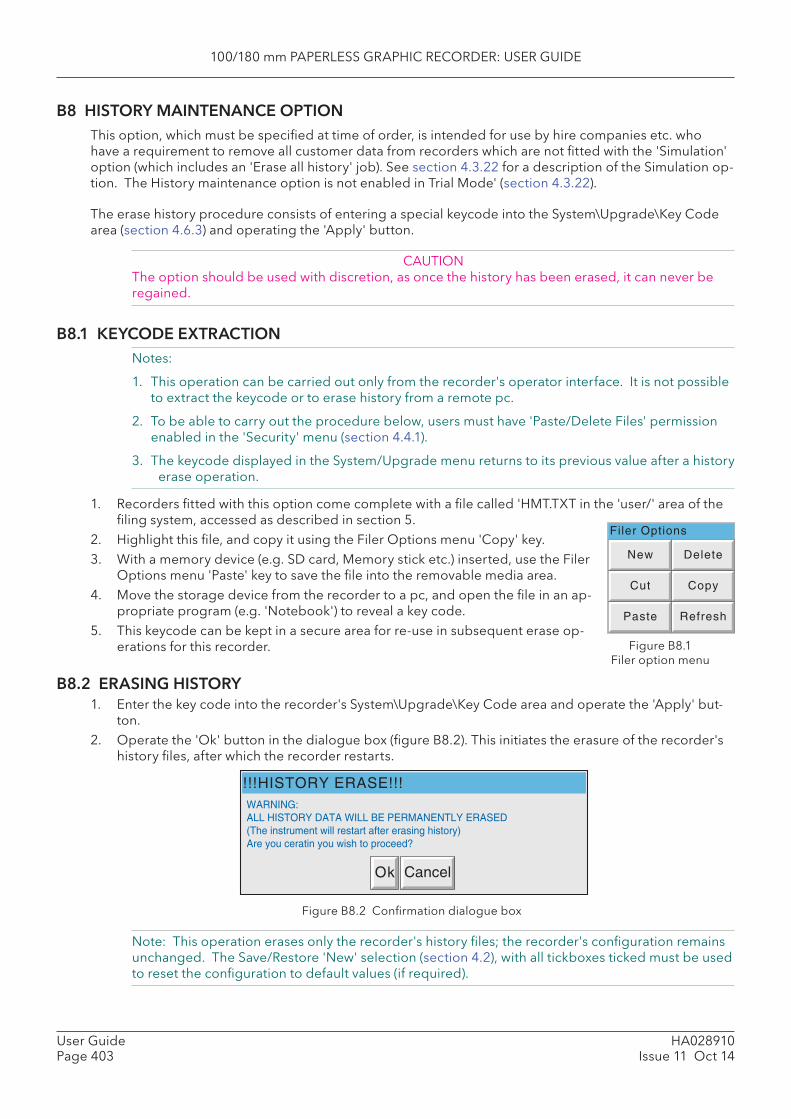
100/180 mm PAPERLESS GRAPHIC RECORDER: USER GUIDE
HA028910Issue 11 Oct 14
User GuidePage 403
B8 HISTORY MAINTENANCE OPTIONThis option, which must be specifi ed at time of order, is intended for use by hire companies etc. who have a requirement to remove all customer data from recorders which are not fi tted with the 'Simulation' option (which includes an 'Erase all history' job). See section 4.3.22 for a description of the Simulation op-tion. The History maintenance option is not enabled in Trial Mode' (section 4.3.22).
The erase history procedure consists of entering a special keycode into the System\Upgrade\Key Code area (section 4.6.3) and operating the 'Apply' button.
CAUTIONThe option should be used with discretion, as once the history has been erased, it can never be regained.
B8.1 KEYCODE EXTRACTION Notes:
1. This operation can be carried out only from the recorder's operator interface. It is not possible to extract the keycode or to erase history from a remote pc.
2. To be able to carry out the procedure below, users must have 'Paste/Delete Files' permission enabled in the 'Security' menu (section 4.4.1).
3. The keycode displayed in the System/Upgrade menu returns to its previous value after a history erase operation.
1. Recorders fi tted with this option come complete with a fi le called 'HMT.TXT in the 'user/' area of the fi ling system, accessed as described in section 5.
2. Highlight this fi le, and copy it using the Filer Options menu 'Copy' key.3. With a memory device (e.g. SD card, Memory stick etc.) inserted, use the Filer
Options menu 'Paste' key to save the fi le into the removable media area.4. Move the storage device from the recorder to a pc, and open the fi le in an ap-
propriate program (e.g. 'Notebook') to reveal a key code.5. This keycode can be kept in a secure area for re-use in subsequent erase op-
erations for this recorder.
B8.2 ERASING HISTORY1. Enter the key code into the recorder's System\Upgrade\Key Code area and operate the 'Apply' but-
ton.2. Operate the 'Ok' button in the dialogue box (fi gure B8.2). This initiates the erasure of the recorder's
history fi les, after which the recorder restarts.
Filer Options
New Delete
Cut Copy
Paste Refresh
Figure B8.1Filer option menu
Figure B8.2 Confi rmation dialogue box
Note: This operation erases only the recorder's history fi les; the recorder's confi guration remains unchanged. The Save/Restore 'New' selection (section 4.2), with all tickboxes ticked must be used to reset the confi guration to default values (if required).
!!!HISTORY ERASE!!!WARNING:ALL HISTORY DATA WILL BE PERMANENTLY ERASED(The instrument will restart after erasing history)Are you ceratin you wish to proceed?
Ok Cancel
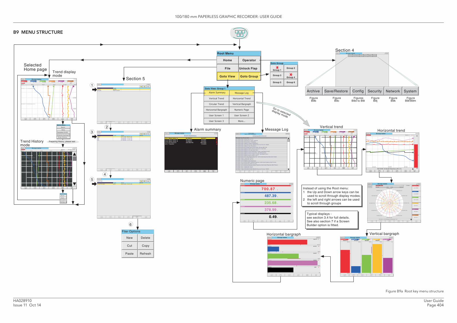
100/180 mm PAPERLESS GRAPHIC RECORDER: USER GUIDE
User GuidePage 404
HA028910Issue 11 Oct 14
Group name 11:52:0405/10/05
11:49:2405/10/05
11:46:4405/10/05
05/10/05 11:47:39 Alarms(s) on 3(1)
05/10/05 11:51:18 Alarms(s) o f f 3(1)
Engineer
Channel 1
400 .00 800 .00
700.87
720 .00640 .00480 .00 560 .00
Channel 1700.87ßC
Channel 2487.39ßC
Channel 3235.68ßC
Channel 4378.99ßC
Channel 50.49V
Channel 60.85V
Group name 14:21:3005/10/05
Engineer
Channel 1 700 .87 ßC
400
800
14:16:2005/10/05
14:13:4005/10/05
14:11:0005/10/05
05/10/05 12:02:20 Alarm(s) off 2 (1)
Home Operator
File
Goto View Goto Group
1
3
5
New Delete
Cut Copy
Paste Refresh
Filer Options
6
Section 5
Section 4Group name 18:10:39
05/10/05Engineer
Archive SystemSave/Restore Config Security Network
Save/RestoreArch ive Conf ig Securi ty Network Sys tem
Group nameChannel 1
18:08:2005/10/05
Logged out
Channel 2
Channel 4
Channel 5
487.39
235.68
378.99
V0.49
700.87
Channel 3
Typical displays -see section 3.4 for full details.See also section 7 if a ScreenBuilder option is fitted.
Instead of using the Root menu:1 the Up and Down arrow keys can be
used to scroll through display modes;2 the left and right arrows can be used
to scroll through groups
Channel 1
400 .00
686 .84 ˚C
640 .00
Group name 11:52:5105/10/05
11:52:0405/10/05
11:49:2405/10/05
14:46:4405/10/05
05/10/05 11:51:18 Alarms(s) of f 3(1)
Trend Historymode
Engineer
Group name 11:52:04
05/10/05
11:49:2405/10/05
11:46:4405/ /05
05/10/05 11:47:39 Alarms(s) on 3(1)
05/10/05 11:51:18 Alarms(s) of f 3(1)
Engineer
Channel 1
400 .00 800 .00
700.87
720 .00640 .00480 .00 560 .00
Channel 1700.87ßC
Channel 2487.39ßC
Channel 3235.68ßC
Channel 4378.99ßC
Channel 50.49V
Channel 60.85V
Trend displaymode
Preparing History, please wait
05/10 /05 11 :49 :50
800 .00720 .00560 .00480 .00
En te r H is to ry
Channel Cycl ing Off
Faceplates On/Off
Ba tch
Note
Option Menu
Alarm Summary
1(1) Water temp 1a 60.0000 C 68.52772 (1) Water temp 1b 30.0000 C 23.45312 (2) Water temp 1b 10.0000 C 23.45313 (1) 0i l pressure 250.000 PSI 260.34254(1) Transfer 15.3678
Group nameEngineer 11:17:5105/10/05
N o t e
Go to selecteddisplay mode
SelectedHome page
Group nameBatch number:020205A12
09:06:2205/10/05
Logged out
05/10/05 09:06:18 Alarm(s) on 1(1)
05/10/05 09:06:18 Operator 's name: Andrew
05/10/05 09:06:18 Customer: F ishesRus
05/10/05 09:06:18 Batch number:020205A12
05/10/05 09:06:18 Conf ig Vers ion:682759 Secur i ty Vers ion 746261
05/10/05 09:06:18 Batch s tar t (Engineer)
05/10/05 08:50:30 Conf igurat ion vers ion 682,759 was 682,758
05/10/05 08:50:28 Batch) Name f i les by batch t rue was fa lse
05/10/05 08:50:28 Batch) On star t log 3 was 1
05/10/05 08:50:28 Batch) F ie ld 3 Operator 's name: was Batch f ie ld 3
05/10/05 08:50:28 Batch) F ie ld 2 Customer: was Batch f ie ld 2
05/10/05 08:50:28 Batch) F ie ld 1 Batch number: was Batch f ie ld 1
05/10/05 08:50:28 Batch) Batch f ie lds 3 was 1
05/10/05 08:50:50 Conf ig ,S igned:Engineer , Author ized:Engineer ,New batch f ie lds
04/10/05 16:42:11 Alarm(s) o f f 2(1)
04/10/05 16:32:50 Alarm(s) o f f 1(1)
04/10/05 16:31:05 Batch s top (Engineer)
04/10/05 16:31:05 Stop Batch,Signed: Engineer ,Author ized: Engineer ,Bel t Fa i lure
04/10/05 16:29:33 Alarm(s) Ackd 1(1) 2(1)
04/10/05 16:31:05 Ack a l l a larms,Signed: Engineer ,Author ized: Engineer ,Bel t Fa i lure
04/10/05 16:27:13 Alarm(s) on1(1)
04/10/05 16:27:13 Alarm(s) on2(1)
04/10/05 14:06:22 Conf ig Vers ion:682759 Secur i ty Vers ion 746261
04/10/05 14:06:22 Batch s tar t (Engineer)
Message Log: Group name
All Messages All History
Group name 11:05:3305/10/05Logged out
Full ScreenFurnace 1 Temp 13
1500.0000 0.0000 0.0000 1500.000
05/10/05 10:10
05/10/05 10:15
05/10/05 10:20
05/10/05 10:25
05/10/05 10:30
05/10/05 10:35
05/10/05 10:40
05/10/05 10:45
05/10/0510:50
05/10/05 10:55
105/10/0511:00
05/10/05 11:05
05/10/05 11:07:52 Engineer ,Restar ted 11:07
Furnace 1Te. .
1125.0956ßC
Furnace 1Te. .
1113.9806ßC
Furnace 1Te. .
1200.9456ßC
Flow 1
1365.21l/ hr
Flow 2
1299.65l/ hr
Flow 3
989.54l/ hr
1 hr/rev
�����������
�����������
�����������������
�����������
�����������
����������
�������������
���������������
������� ���
����������!
����"""
#���������$
Group name 18:09:4705/10/05Logged out
Channel 1
400.00 800.00
700.87˚C
Channel 2
400.00 800.00
487.39˚C
Channel 3
0.00 400.00
235.68˚C
Channel 4
0.00 400.00
378.99˚C
Channel 5
0.00 1.00
0.49V
Group name 10:43:5005/10/05
Logged out
400.00
800.00
Channel 1700.87˚C
400.00
800.00
Channel 2487.39˚C
Channel 3235.68˚C
0.00
400.00
Channel 4378.99˚C
0.00
1.00
Channel 50.49V
0.00
400.00
05/10/05 14:47:39 Alarms(s) on 3(1)
B a t c h
Ex i t H i s t o-ry
Message Log
\
Name
\Pcard\ Removable
17:06:4105/10/05
Hide
2
Engineer
\user \
Name Type Date Bytes
\user\cal\
Name Type Date Bytes
4
Engineer
Eng ineer
17:07:3905/10/05
Hide
17:08:0805/10/05
Hide
\user \
sdb\user \ 04/10/05 08:57:03
01/10/05 10:14:56l ib\ 29/09/05 14:25:13cal \ 01/09/05 10:13:48
TypeFlash
TouchScreen uha 03/10/05 10:13:48
FigureB9b
FigureB9c
FiguresB9d to B9i
FigureB9j
FigureB9k
FigureB9l/B9m
Option Menu
Root Menu
Goto View: Group 1
Goto Group
Group 1Group 2
Group 3Group 4
Group 5 Group 6
Unlock Flap
Vertical trendHorizontal trend
Vertical bargraphHorizontal bargraph
Numeric page
Message LogAlarm summary
B9 MENU STRUCTURE
Figure B9a Root key menu structure
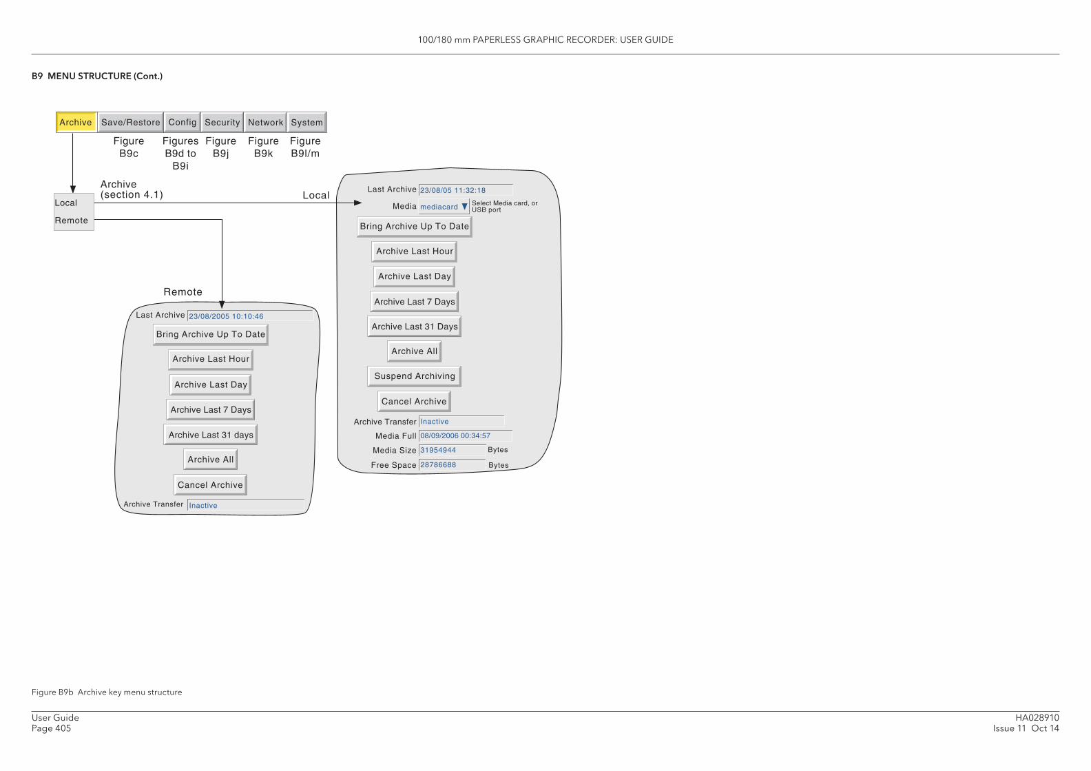
100/180 mm PAPERLESS GRAPHIC RECORDER: USER GUIDE
HA028910Issue 11 Oct 14
User GuidePage 405
Last Archive
Archive Last Hour
Archive Last Day
Archive Last 7 Days
Archive Last 31 Days
Archive All
Suspend Archiving
Cancel Archive
Bring Archive Up To Date
23/08/05 11:32:18
Media mediacard Select Media card, orUSB port
Archive SystemSave/Restore Config Security Network
Local
Last Archive
Archive Last Hour
Archive Transfer
Archive Last Day
Archive Last 7 Days
Archive Last 31 days
Archive All
Cancel Archive
Bring Archive Up To Date
23/08/2005 10:10:46
Inactive
Archive(section 4.1)
Remote
Local
Remote
FigureB9c
FiguresB9d to
B9i
FigureB9j
FigureB9k
FigureB9l/m
Bytes
Bytes
Archive Transfer
Media Size
Free Space
Inactive
31954944
28786688
Media Full 08/09/2006 00:34:57
B9 MENU STRUCTURE (Cont.)
Figure B9b Archive key menu structure
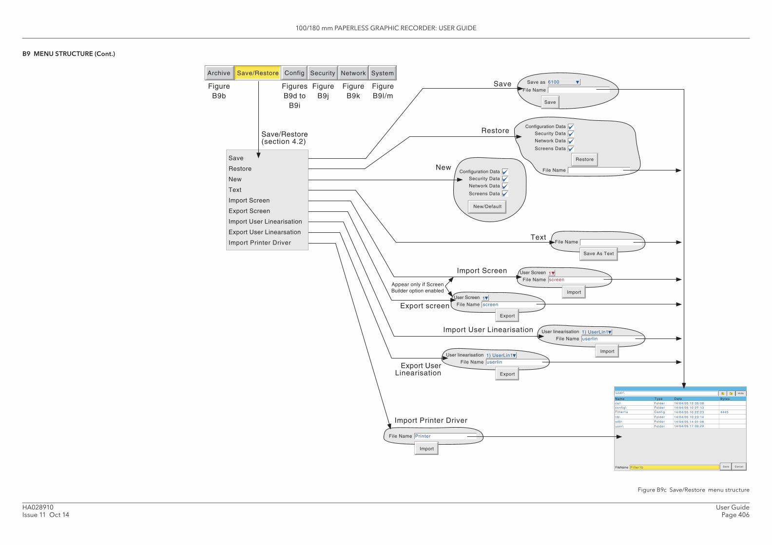
100/180 mm PAPERLESS GRAPHIC RECORDER: USER GUIDE
User GuidePage 406
HA028910Issue 11 Oct 14
\user \
ca l \conf ig \
l ib \
FolderFolder
Folder
FileName Fi l ter1b
sdb\ Folder
user \ Folder
14/04/05 12:35:0814/04/05 10:27:13
14/04/05 10:23:14
14/04/05 14:01:0814/04/05 17:30:29
Fi l ter1a Conf ig 14/04/05 10:22:23 4445
Save Cancel
Hide
TypeName Date Bytes
File Name1User Screen
screen
Export
New
New/Default
Network Data
Screens Data
Security Data
Configuration Data
File Name
Import
Printer
File Name1) UserLin1User linearisation
userlin
Export
File Name
Save As Text
File Name
Import
1User Screen
screen
Save
Restore
Text
Import Screen
Export screen
File Name
Network Data
Screens Data
Security Data
Configuration Data
Restore
File Name
Save
Save as
File Name1) UserLin1User linearisation
userlin
Import
Import User Linearisation
Export UserLinearisation
6100
Save/Restore(section 4.2)
Archive SystemSave/Restore Config Security Network
Save
Restore
New
Text
Import Screen
Export Screen
Import User Linearisation
Export User Linearsation
Import Printer Driver
Appear only if ScreenBuilder option enabled
FigureB9b
FiguresB9d to
B9i
FigureB9j
FigureB9k
FigureB9l/m
Import Printer Driver
B9 MENU STRUCTURE (Cont.)
Figure B9c Save/Restore menu structure
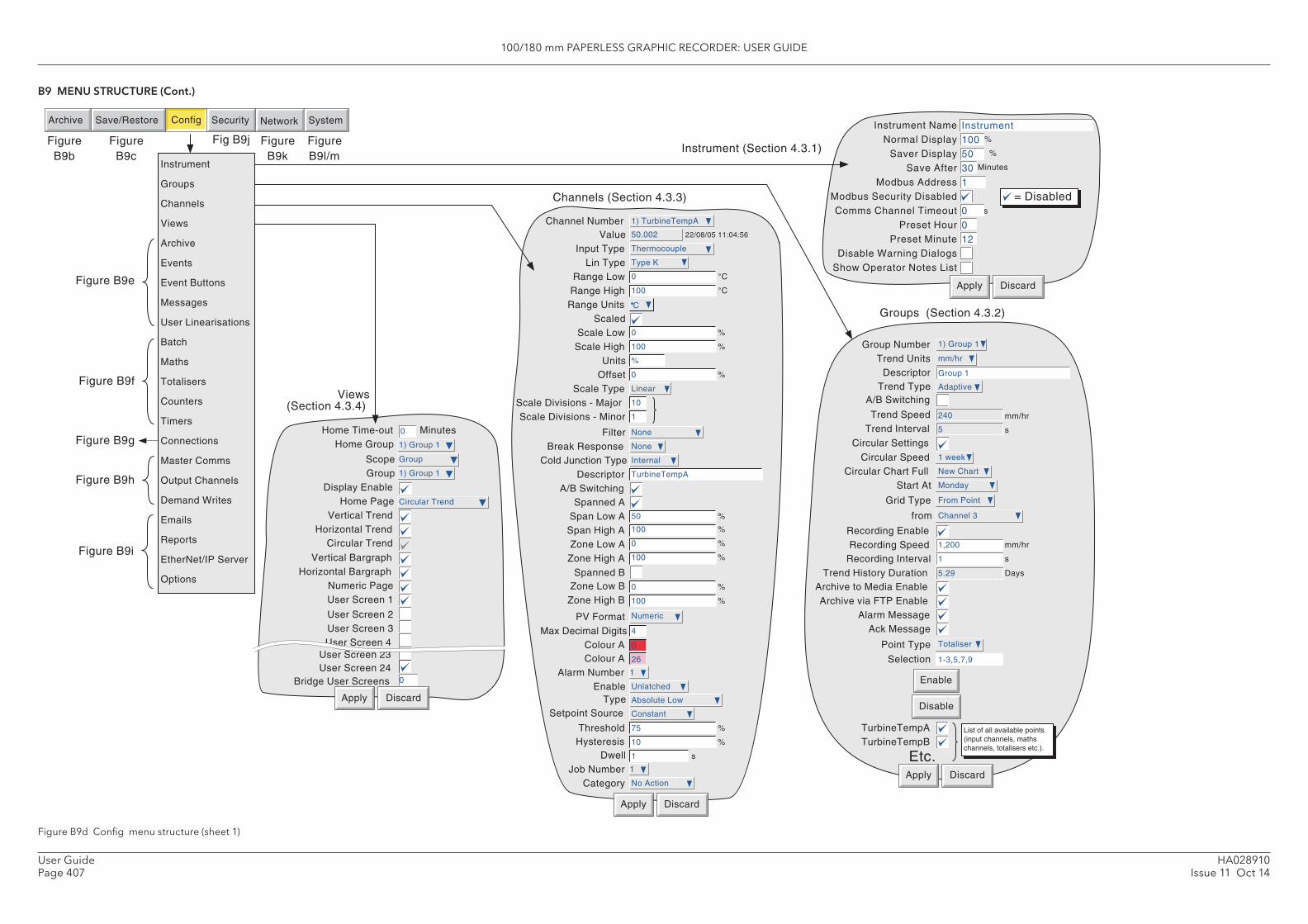
100/180 mm PAPERLESS GRAPHIC RECORDER: USER GUIDE
HA028910Issue 11 Oct 14
User GuidePage 407
Apply Discard
Alarm Message
Recording SpeedRecording Interval
Archive to Media EnableArchive via FTP Enable
Trend History Duration
Recording Enable
Ack Message
TurbineTempATurbineTempB
Etc.
1
1,200 mm/hr
s
List of all available points (input channels, maths channels, totalisers etc.).
5.29 Days
Trend UnitsDescriptor
Trend SpeedTrend Interval
Group Number
Trend Type
mm/hr
5
240 mm/hr
s
Group 1
1) Group 1
Adaptive
Circular Speed 1 week
Circular Chart Full New Chart
Start At Monday
Circular Settings
Grid Type From Point
from Channel 3
A/B Switching
Point Type Totaliser
Selection 1-3,5,7,9
Enable
Disable
Groups (Section 4.3.2)
%
%
Minutes
s
= Disabled
0
Instrument 100 50 30 1
0 12
Apply Discard
Instrument Name Normal Display
Saver Display Save After
Modbus Address Modbus Security Disabled Comms Channel Timeout 0
Preset Hour Preset Minute
Disable Warning Dialogs Show Operator Notes List
Instrument (Section 4.3.1)
Home Time-outHome Group
ScopeGroup
Display EnableHome Page
Vertical TrendHorizontal Trend
Vertical BargraphHorizontal Bargraph
Numeric PageUser Screen 1
User Screen 2User Screen 3User Screen 4
1) Group 1
Apply Discard
0
Group
1) Group 1
Circular Trend
Minutes
Circular Trend
User Screen 23User Screen 24
Bridge User Screens 0
Views (Section 4.3.4)
Channels (Section 4.3.3)
Job Number 1
Category No Action
Value 50.002
Input Type Thermocouple
Lin Type Type K
Range Low 0 C
Range High 100 C
Range Units C
ScaledScale Low 0 %
Scale High 100 %
Units %
Offset 0 %
Filter None
Break Response None
Cold Junction Type Internal
Descriptor TurbineTempA
Spanned ASpan Low A 50 %
Span High A 100 %
Zone Low A 0 %
Zone High A 100 %
Max Decimal Digits 4
Colour A
Alarm Number 1
Enable Unlatched
0
Channel Number 1) TurbineTempA
22/08/05 11:04:56
Type Absolute Low
ThresholdHysteresis
Dwell
75 %
10 %
1 s
Scale TypeScale Divisions - Major 10
1Scale Divisions - Minor
Linear
PV Format Numeric
A/B Switching
Spanned BZone Low B 0 %
Zone High B 100 %
Archive SystemSave/Restore Config Security Network
Instrument
Groups
Channels
Views
Archive
Events
Event Buttons
Messages
User Linearisations
Batch
Maths
Totalisers
Counters
Timers
Connections
Master Comms
Output Channels
Demand Writes
Emails
Reports
EtherNet/IP Server
Options
Figure B9b
Figure B9c
Fig B9j Figure B9k
Figure B9l/m
Figure B9e
Figure B9f
Figure B9h
Figure B9g
Colour A 26
Apply Discard
Setpoint Source Constant
Figure B9i
B9 MENU STRUCTURE (Cont.)
Figure B9d Confi g menu structure (sheet 1)
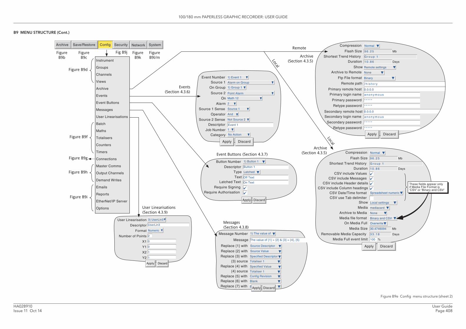
100/180 mm PAPERLESS GRAPHIC RECORDER: USER GUIDE
User GuidePage 408
HA028910Issue 11 Oct 14
Archive to Remote
Remote path
Show
Primary remote host
Primary login name
Primary password
Retype password
Secondary remote hostSecondary login name
Secondary password
Retype password
Compression
Flash Size Mb
Shortest Trend HistoryDuration Days
Ftp File format
Apply Discard
None
Remote settings
0.0.0.0
a n o n y m o u s
* * * * *
* * * * *
0.0.0.0
a n o n y m o u s
* * * * *
* * * * *
/ h i s t o r y
Normal
9 6 . 2 5
G r o u p 1
1 0 . 8 6
Binary
Apply Discard
On Media Full
Media Size Mb
Media Full event limit
Removable Media Capacity Days
%
Archive to Media
Compression
Flash Size Mb
Shortest Trend History
Show
Duration Days
Media file format
CSV include ValuesCSV include Messages
CSV include Header detailsCSV include Column headings
CSV Date/Time formatCSV use Tab delimiter
These fields appear only if Media File Format is 'CSV' or 'Binary and CSV'
Media
30.4746094
Overwrite
3 3 . 1 8
100
None
Normal
9 6 . 2 5
G r o u p 1
Local settings
1 0 . 8 6
Binary and CSV
Spreadsheet numeric
mediacard
Messages �
(Section 4.3.8)
Blank
Message Number
Message
Replace {1} with
Replace {2} with
Replace {3} with{3} source
Replace {4} with{4} source
Replace {5} withReplace {6} with
1) The value of
The value of {1} = {2} & {3} = {4}, {5}
Source Descriptor
Source Value
Totaliser 1
Specified Descriptor
Totaliser 1
Specified Value
Config Revision
Blank
Apply DiscardReplace {7} with
Button Number
DescriptorType
TextLatched Text
Require Signing
Require Authorisation
Apply Discard
1) Button 1
Button 1
Latched
Off Text
On Text
Event Buttons (Section 4.3.7)
User Linearisation
Descriptor
Format
Number of Points
X1
Y1
X2
Apply Discard
Y2
3) UserLin3
Numeric
2
0
0
1
1
UserLin3
Apply Discard
Event NumberSource 1
Descriptor
Job NumberCategory
On Group
Source 2
On
Alarm
Source 1 Sense
Operator
Source 2 Sense
Events �
(Section 4.3.6)
User Linearisations �
(Section 4.3.9)
Archive �
(Section 4.3.5)
Remote
Local
Archive SystemSave/Restore Config Security Network
Instrument
Groups
Channels
Views
Archive
Events
Event Buttons
Messages
User Linearisations
Batch
Maths
Totalisers
Counters
Timers
Connections
Master Comms
Output Channels
Demand Writes
Emails
Reports
EtherNet/IP Server
Options
Figure
B9b
Figure
B9c
Fig B9j Figure
B9k
Figure
B9l/m
Figure B9f
Figure B9h
Figure B9g
Figure B9d
1) Event 1
Event 1
1
No Action
Alarm on Group
1) Group 1
Point Alarm
Math 12
2
Source 1
And
Not Source 2
Archive �
(Section 4.3.5)
Local
Figure B9i
B9 MENU STRUCTURE (Cont.)
Figure B9e Confi g menu structure (sheet 2)
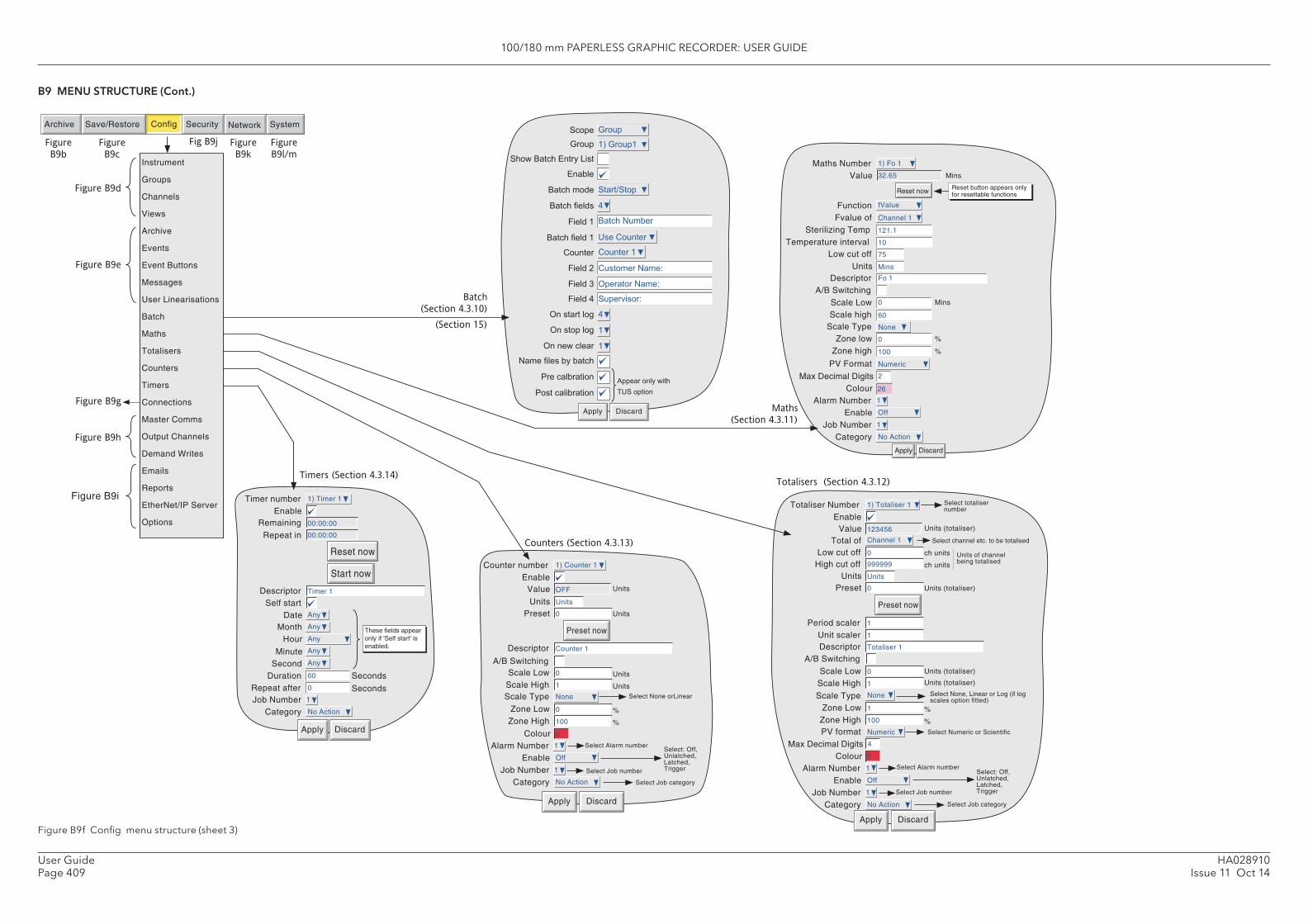
100/180 mm PAPERLESS GRAPHIC RECORDER: USER GUIDE
HA028910Issue 11 Oct 14
User GuidePage 409
Timer numberEnable
Remaining
Start now
DescriptorSelf start
DateMonth
Repeat in
Reset now
Apply Discard
SecondDuration
Job Number
Minute
Repeat after
Category
Hour
Seconds
Seconds
These fields appear only if 'Self start' is enabled.
Any
Any
Any
Any
Any
1) Timer 1
00:00:00
Timer 1
00:00:00
1
No Action
60
0
Apply Discard
Totaliser Number Select totaliser number
Enable
Select Alarm numberAlarm NumberEnable
Job NumberCategory
Select: Off, Unlatched, Latched, Trigger Select Job number
Select Job category
ValueTotal of
Low cut offHigh cut off
UnitsPreset
Preset now
Select channel etc. to be totalised
ch units
ch units
Units of channel being totalised
Units (totaliser)
Period scalerUnit scalerDescriptor
Units (totaliser)
Scale LowScale High
Units (totaliser)
Units (totaliser)
Zone LowZone High
%
%
Max Decimal DigitsColour
Scale Type Select None, Linear or Log (if log scales option fitted)
PV format Select Numeric or Scientific
A/B Switching
1) Totaliser 1
1
Off
1
No Action
Channel 1
123456
0
999999
Units
0
1
1
Totaliser 1
0
1
1
100
4
0
None
Numeric
������
���
���
������������������
���������
�������
�������������
������������
�����
�������
�������
������
!��������"
!�������"
!����������
#������������������
$����������
$������������
Apply Discard
���
�%�����
���& ��
������#����
'��������
�������
�������#���(
!�����#���(
���)��(
�
�
Batch
(Section 4.3.10)
(Section 15)
Apply Discard
FunctionFvalue of
Sterilizing Temp
Low cut off
Descriptor
Scale Low Mins
Scale TypeZone low
Zone high
Max Decimal DigitsColour
Alarm NumberEnable
Job NumberCategory
%
%
Maths NumberValue 32.65
Reset now
Mins
Reset button appears only for resettable functions
PV Format
Temperature interval
Units
Scale high
A/B Switching
fValue
121.1
Fo 1
0
None
0
2
1
Off
1
No Action
26
Channel 1
75
100
1) Fo 1
Numeric
10
Mins
60
Maths �
(Section 4.3.11)
Totalisers (Section 4.3.12)
Apply Discard
Counter numberEnable
Select Alarm numberAlarm NumberEnable
Job NumberCategory
Select: Off, Unlatched, Latched, Trigger Select Job number
Select Job category
Value
UnitsPreset
Preset now
Units
Descriptor
Units
Scale LowScale High
Units
Units
Zone LowZone High
%
%
Colour
Scale Type
A/B Switching
Select None orLinear
1) Counter 1
1
Off
1
No Action
OFF
Units
0
Counter 1
0
1
0
100
0
None
Counters (Section 4.3.13)
Archive SystemSave/Restore Config Security Network
Figure
B9b
Figure
B9c
Fig B9j Figure
B9k
Figure
B9l/mInstrument
Groups
Channels
Views
Archive
Events
Event Buttons
Messages
User Linearisations
Batch
Maths
Totalisers
Counters
Timers
Connections
Master Comms
Output Channels
Demand Writes
Emails
Reports
EtherNet/IP Server
Options
Figure B9e
Figure B9d
Figure B9h
Figure B9g
Timers (Section 4.3.14)
Figure B9i
*��������������
+' �����
B9 MENU STRUCTURE (Cont.)
Figure B9f Confi g menu structure (sheet 3)
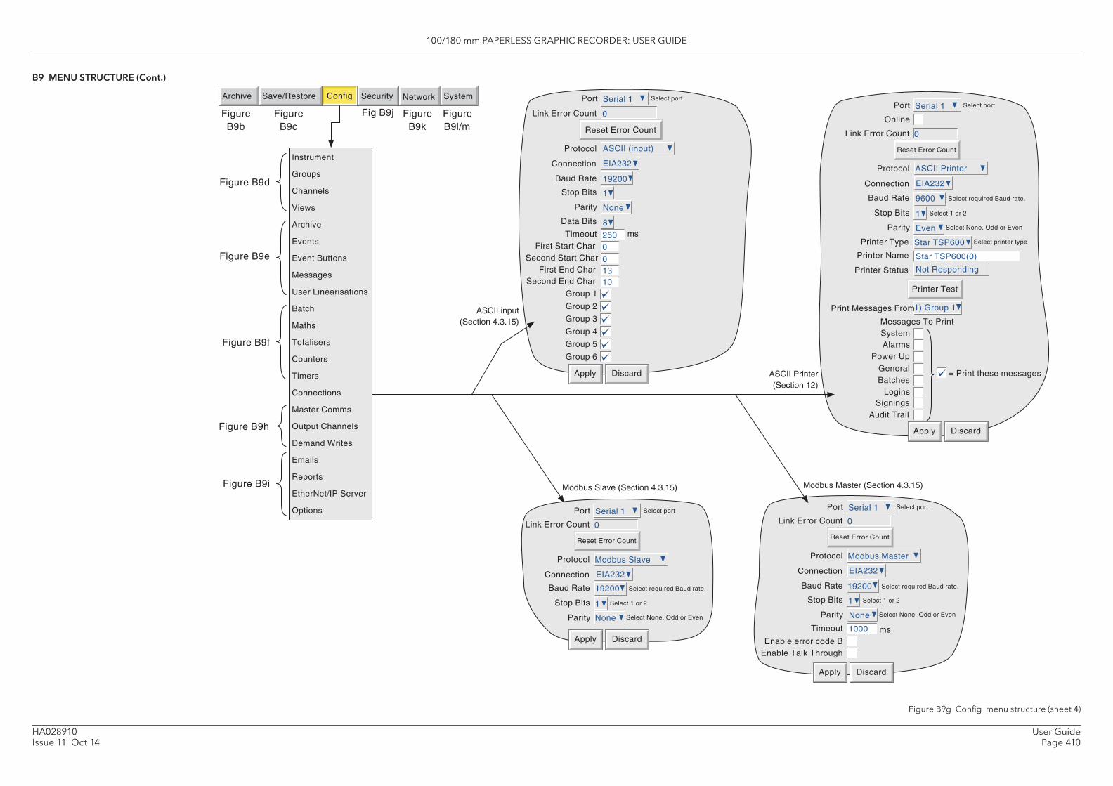
100/180 mm PAPERLESS GRAPHIC RECORDER: USER GUIDE
User GuidePage 410
HA028910Issue 11 Oct 14
Archive SystemSave/Restore Config Security Network
Figure B9b
Figure B9c
Fig B9j Figure B9k
Figure B9l/m
Protocol
Link Error Count
Reset Error Count
Online
Connection
Port Select port
Baud Rate Select required Baud rate.
Stop Bits
Parity
Printer Type
Printer Name
Printer Status
SystemAlarms
Power Up
Select 1 or 2
Select None, Odd or Even
Select printer type
Printer Test
Print Messages From
Messages To Print
General= Print these messages
BatchesLogins
Apply Discard
SigningsAudit Trail
Apply Discard
250
Baud Rate
Stop Bits
Parity
Data Bits
TimeoutFirst Start Char
Second Start CharFirst End Char
Second End Char
Group 1
Group 2
Group 3
Group 4
Group 5
Group 6
19200
1
None
8ms
0
13
Link Error Count 0
0
10
Reset Error Count
ASCII input (Section 4.3.15)
Protocol ASCII (input)
Apply Discard
Baud Rate
Stop Bits
Parity
Select required Baud rate.
Select 1 or 2
Select None, Odd or Even
Timeout msEnable error code B
Enable Talk Through
Protocol
Link Error Count
Reset Error Count
Connection
Port Select port
19200
1
None
1000
Modbus Master
0
EIA232
Serial 1
Modbus Master (Section 4.3.15)
Apply Discard
Baud Rate
Stop Bits
Parity
Select required Baud rate.
Select 1 or 2
Select None, Odd or Even
Protocol
Link Error Count
Reset Error Count
Connection
Port Select port
19200
1
None
Modbus Slave
0
EIA232
Serial 1
Modbus Slave (Section 4.3.15)
ASCII Printer (Section 12)
Port Serial 1 Select port
Connection EIA232ASCII Printer
0
EIA232
Serial 1
9600
1
Even
Star TSP600
Star TSP600(0)
Not Responding
1) Group 1
Instrument
Groups
Channels
Views
Archive
Events
Event Buttons
Messages
User Linearisations
Batch
Maths
Totalisers
Counters
Timers
Connections
Master Comms
Output Channels
Demand Writes
Emails
Reports
EtherNet/IP Server
Options
Figure B9e
Figure B9f
Figure B9h
Figure B9d
Figure B9i
B9 MENU STRUCTURE (Cont.)
Figure B9g Confi g menu structure (sheet 4)
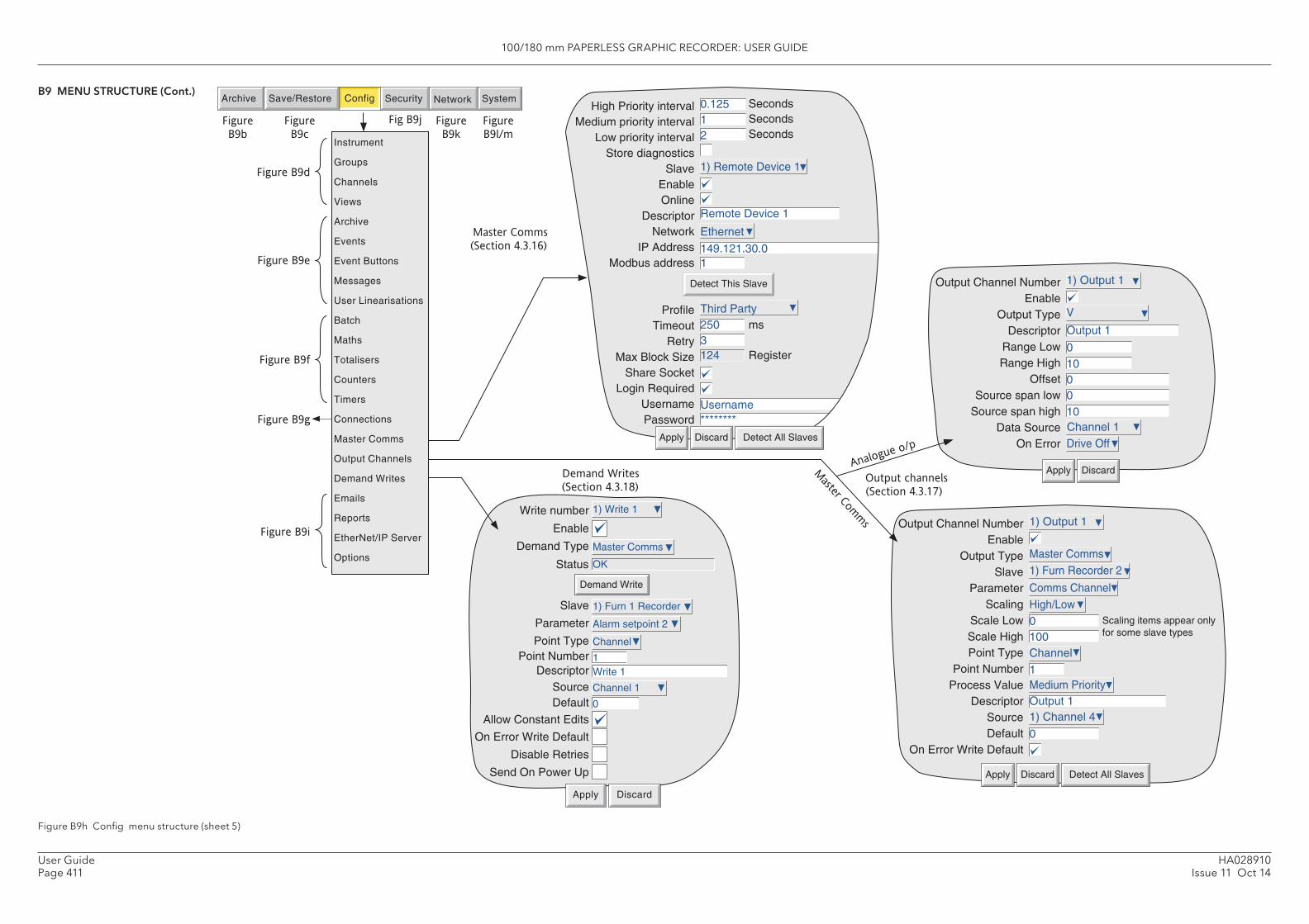
100/180 mm PAPERLESS GRAPHIC RECORDER: USER GUIDE
HA028910Issue 11 Oct 14
User GuidePage 411
Detect This Slave
High Priority interval Medium priority interval
Low priority interval Store diagnostics
Slave Enable Online
Descriptor Network
IP Address Modbus address
Profile Timeout
Retry Max Block Size
Share Socket Login Required
Username Password
0.125 1 2 1) Remote Device 1
Remote Device 1
149.121.30.0
Ethernet
1
Third Party2503124
ms
Register
SecondsSecondsSeconds
Username********
Detect All SlavesDiscardApply
Output Channel Number Enable
Output Type Slave
Parameter Scaling
Scale Low Scale High Point Type
Point Number Process Value
Descriptor Source Default
On Error Write Default
Detect All SlavesDiscardApply
Scaling items appear only for some slave types
Output channels �
(Section 4.3.17)
Enable
Demand Type
Status
Apply Discard
Write number
Demand Write
Slave
Parameter
Point TypePoint Number
DescriptorSourceDefault
Allow Constant Edits
Disable Retries
Send On Power Up
On Error Write Default
Master Comms
1) Write 1
OK
1) Furn 1 Recorder
Alarm setpoint 2
Channel
1Write 1
Channel 1
0
Demand Writes
(Section 4.3.18)
Master Comms �
(Section 4.3.16)
1) Output 1
Master Comms1) Furn Recorder 2
Comms Channel
Channel
Medium Priority
1) Channel 4
High/Low0100
0
1
Output 1
Archive SystemSave/Restore Config Security Network
Instrument
Groups
Channels
Views
Archive
Events
Event Buttons
Messages
User Linearisations
Batch
Maths
Totalisers
Counters
Timers
Connections
Master Comms
Output Channels
Demand Writes
Emails
Reports
EtherNet/IP Server
Options
Figure
B9b
Figure
B9c
Fig B9j Figure
B9k
Figure
B9l/m
Figure B9e
Figure B9f
Figure B9i
Figure B9g
Figure B9d
Output Channel Number Enable
Output Type Descriptor
Range Low Range High
Offset Source span low
Source span high Data Source
On Error
1) Output 1
DiscardApply
V
Drive OffChannel 1
00
Output 1
010
10
Analogue o/p
Master C
om
ms
B9 MENU STRUCTURE (Cont.)
Figure B9h Confi g menu structure (sheet 5)
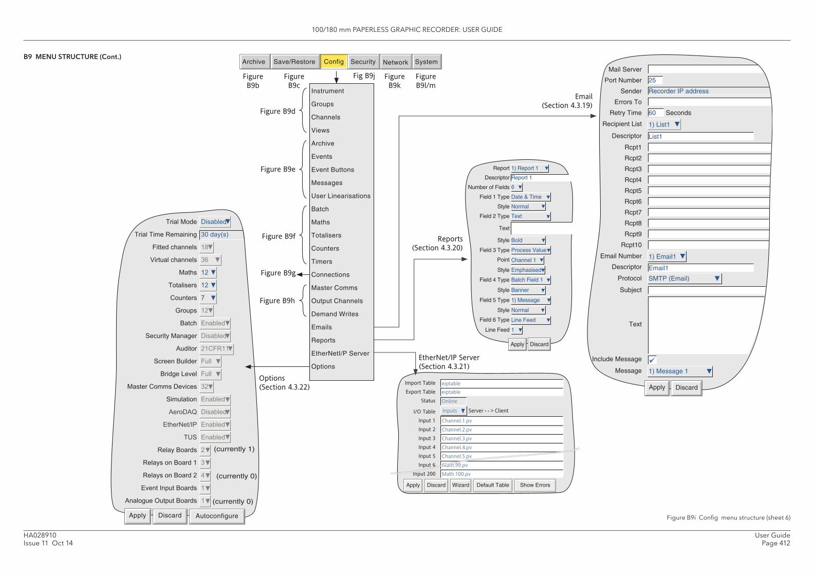
100/180 mm PAPERLESS GRAPHIC RECORDER: USER GUIDE
User GuidePage 412
HA028910Issue 11 Oct 14
+����,�� -��������
+����+����.�������" �/����0�%�
��������������� �1�
2�������������� �3�
,���� ���
+������� ���
������ 4�
���� ���
����� ��������
�������,���"� -��������
*���� ����.���
����������� �����
���"����)�� �����
,����������-�)���� ���
�������� ��������
*�-*5 -��������
����#��&6$ ��������
+' ��������
.��������� ��
.������������� ��
.������������� �
�)����6��������� ��
*���"���!���������� �
(currently 1)
(currently 0)
(currently 0)
Apply Discard Autoconfigure
Number of Fields
Report
Descriptor
Field 1 Type
Style
Field 2 Type
Text
Style
Field 3 Type
Point
Style
Field 4 Type
Style
Field 5 Type
Style
Field 6 Type
Line Feed
Apply Discard
Bold
Process Value
Channel 1
Emphasised
Batch Field 1
1) Message
Normal
Line Feed
1
1) Report 1
Date & Time
Normal
Text
Report 1
6
Banner
Seconds
Apply Discard
Mail Server
Port Number
Sender
Errors To
Retry Time
Recipient List
Descriptor
Rcpt1
Rcpt2
Rcpt3
Rcpt4
Rcpt5
Rcpt6
Rcpt7
Rcpt8
Rcpt9
Rcpt10
Email Number
Descriptor
Protocol
Subject
Text
Include Message
Message
25
Recorder IP address
60
1) List1
List1
1) Email1
Email1
SMTP (Email)
1) Message 1
Archive SystemSave/Restore Config Security Network
Figure
B9b
Figure
B9c
Fig B9j Figure
B9k
Figure
B9l/m
Figure B9e
Figure B9f
Figure B9h
Figure B9g
Figure B9d
Import Table
Export Table
Status
I/O Table
Input 1
Input 2
Input 3
Input 4
Input 5
Input 6
Input 200
eiptable
eiptable
Online
Inputs Server - - > Client
Channel.1.pv
Channel.2.pv
Channel.3.pv
Channel.4.pv
Channel.5.pv
Ch
Apply Discard Wizard Default Table Show Errors
Options
(Section 4.3.22)
EtherNet/IP Server
(Section 4.3.21)
Reports
(Section 4.3.20)
(Section 4.3.19)
Instrument
Groups
Channels
Views
Archive
Events
Event Buttons
Messages
User Linearisations
Batch
Maths
Totalisers
Counters
Timers
Connections
Master Comms
Output Channels
Demand Writes
Emails
Reports
EtherNetI/P Server
Options
B9 MENU STRUCTURE (Cont.)
Figure B9i Confi g menu structure (sheet 6)
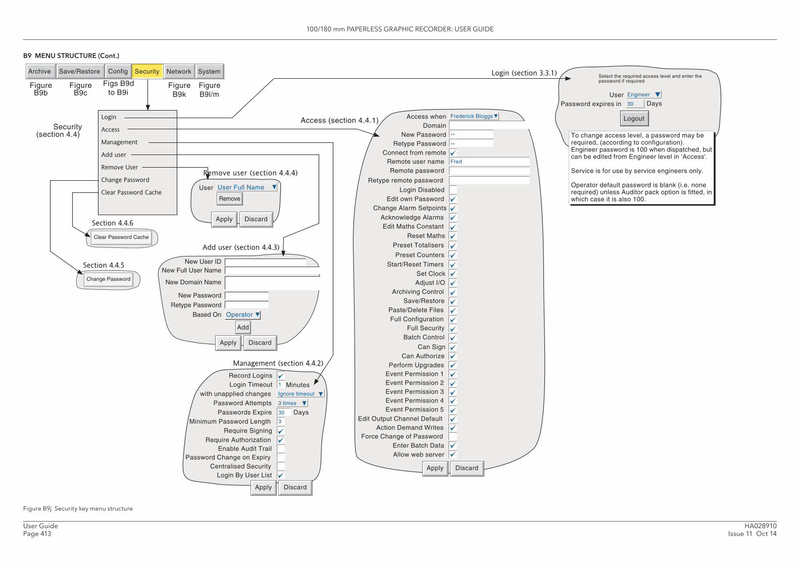
100/180 mm PAPERLESS GRAPHIC RECORDER: USER GUIDE
HA028910Issue 11 Oct 14
User GuidePage 413
Frederick BloggsAccess when Domain
New Password Retype Password
Connect from remote
Login Disabled
Change Alarm SetpointsEdit own Password
Remote user name Fred
Remote password
**
**
Retype remote password
Edit Maths Constant
Set Clock
Archiving ControlSave/Restore
Paste/Delete FilesFull Configuration
Full Security
Apply Discard
Batch Control
Preset Counters
Adjust I/O
Reset Maths
Preset Totalisers
Start/Reset Timers
Acknowledge Alarms
Can SignCan Authorize
Event Permission 1Event Permission 2Event Permission 3Event Permission 4Event Permission 5
Edit Output Channel DefaultAction Demand Writes
Force Change of Password
Perform Upgrades
Enter Batch DataAllow web server
Operator
Apply Discard
Add
New Full User NameNew User ID
New Domain Name
New Password
Retype Password
Based On
Add user (section 4.4.3)
Access (section 4.4.1)
User User Full Name
Apply Discard
Remove
Record Logins
with unapplied changes
Minimum Password Length
Enable Audit TrailRequire Authorization
Apply Discard
Login Timeout
Password AttemptsPasswords Expire
Require Signing
Days
Minutes
Password Change on ExpiryCentralised Security
Login By User List
Management (section 4.4.2)
Security (section 4.4)
Archive SystemSave/Restore Config Security Network
Figure B9b
Figs B9d to B9i
Figure B9k EngineerUser
To change access level, a password may be required, (according to configuration). Engineer password is 100 when dispatched, but can be edited from Engineer level in 'Access'. Service is for use by service engineers only. Operator default password is blank (i.e. none required) unless Auditor pack option is fitted, in which case it is also 100.
Select the required access level and enter the password if required
Logout
30 DaysPassword expires in
Login (section 3.3.1)
Remove user (section 4.4.4)
Figure B9l/m
Figure B9c
1
3 times
30
3
Ignore timeout
Login
Access
Management
Add user
Remove User
Change Password
Clear Password Cache
Change Password
Section 4.4.5
Clear Password Cache
Section 4.4.6
B9 MENU STRUCTURE (Cont.)
Figure B9j Security key menu structure
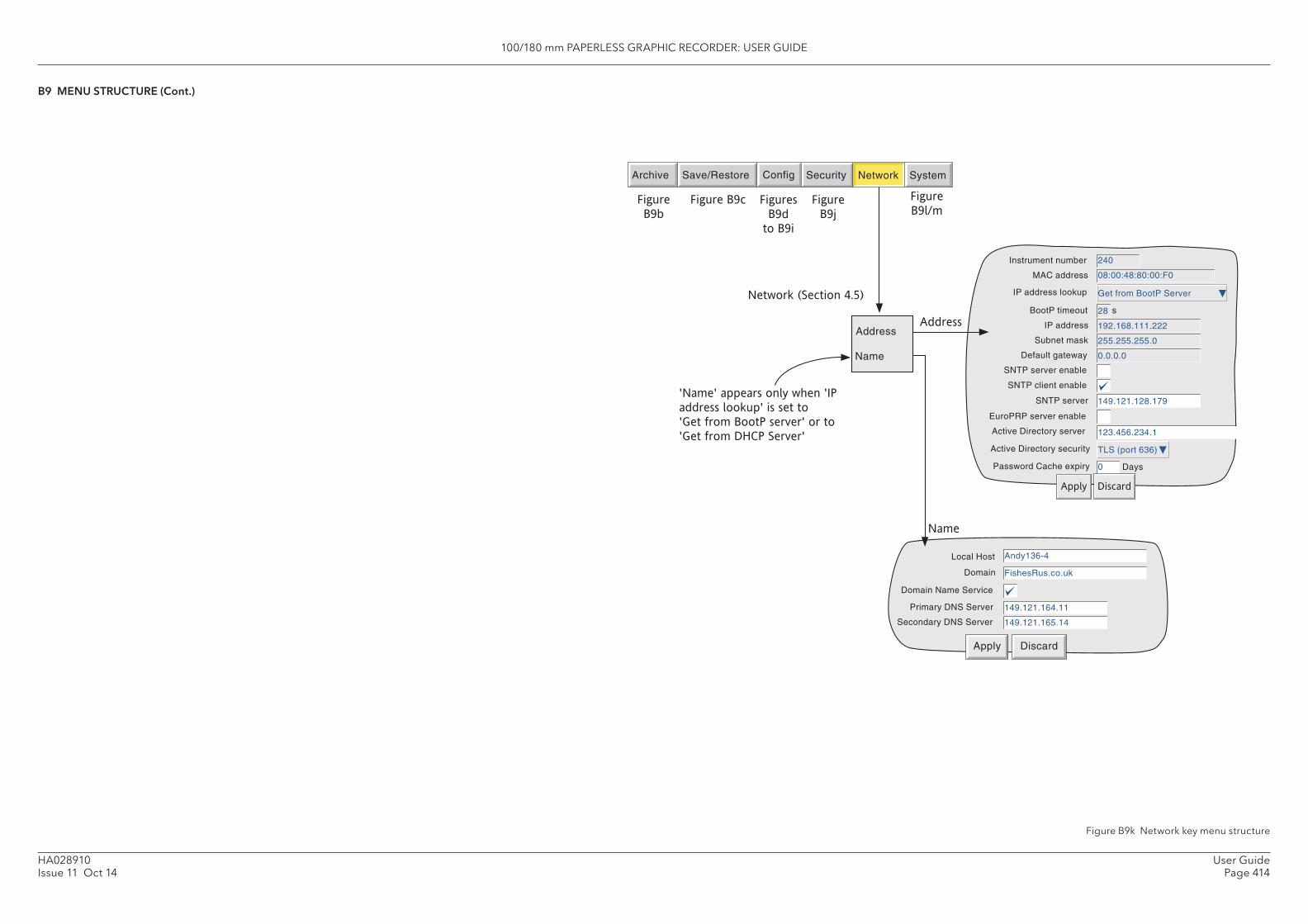
100/180 mm PAPERLESS GRAPHIC RECORDER: USER GUIDE
User GuidePage 414
HA028910Issue 11 Oct 14
MAC address
IP address lookup
IP address
Subnet mask 255.255.255.0
Default gateway 0.0.0.0
192.168.111.222
Instrument number 240
08:00:48:80:00:F0
Get from BootP Server
BootP timeout 28 s
SNTP server enable
SNTP server 149.121.128.179
SNTP client enable
EuroPRP server enable
123.456.234.1
Active Directory security TLS (port 636)
Apply Discard
Days0
Active Directory server
Password Cache expiry
Address
Domain Name Service
Primary DNS Server
Secondary DNS Server
Local Host
Domain
Name
Apply Discard
Address
Name
Figure
B9b
Archive SystemSave/Restore Config Security Network
Figures
B9d
to B9i
Figure
B9j
Network (Section 4.5)
Figure
B9l/mFigure B9c
Andy136-4
149.121.164.11
149.121.165.14
FishesRus.co.uk
'Name' appears only when 'IP
address lookup' is set to �
'Get from BootP server' or to �
'Get from DHCP Server'
B9 MENU STRUCTURE (Cont.)
Figure B9k Network key menu structure
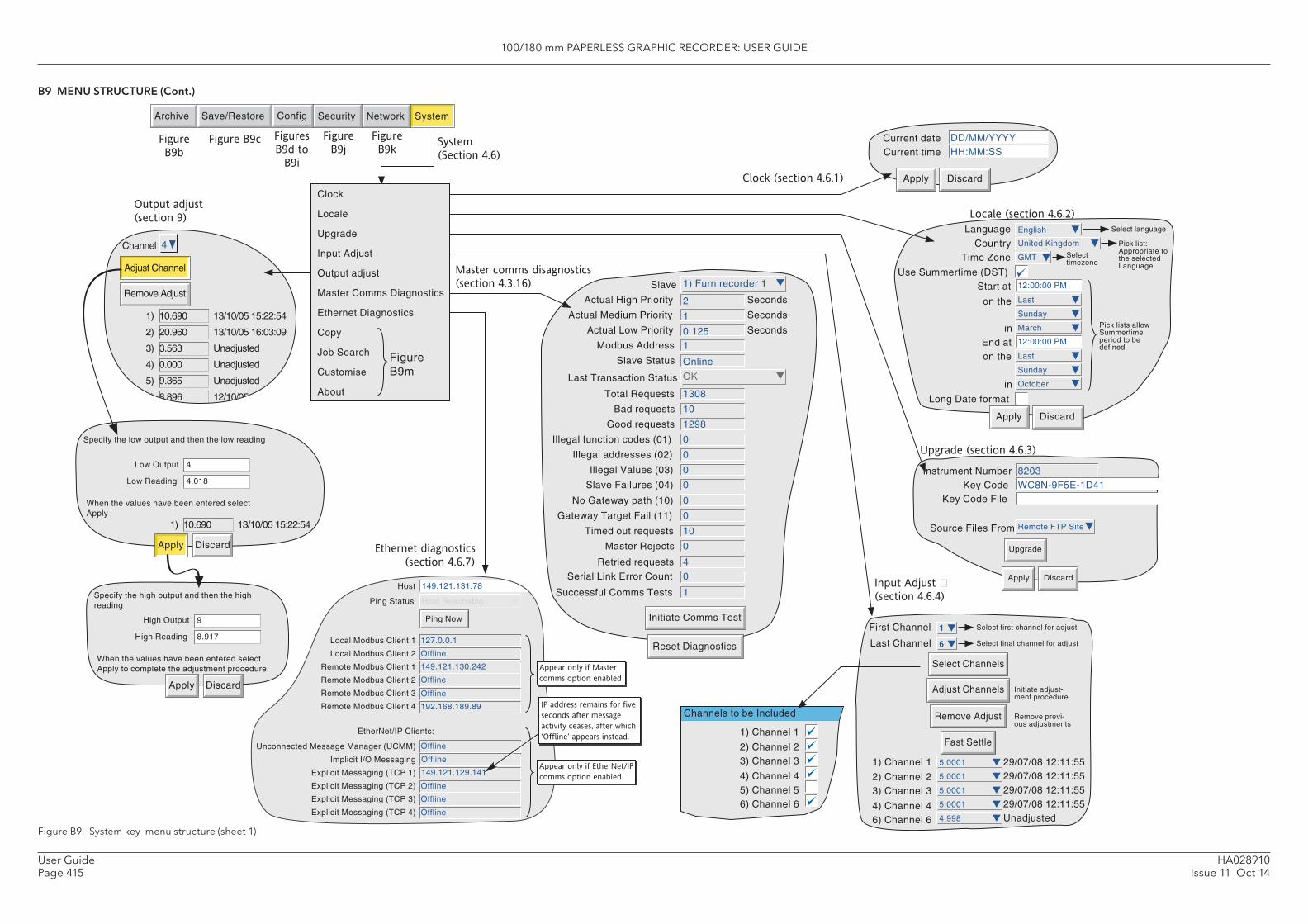
100/180 mm PAPERLESS GRAPHIC RECORDER: USER GUIDE
HA028910Issue 11 Oct 14
User GuidePage 415
Host
Ping Status
149.121.131.78
Host Reachable
Ping Now
Local Modbus Client 1
Local Modbus Client 2
Remote Modbus Client 1
Remote Modbus Client 2
Remote Modbus Client 3
Remote Modbus Client 4
127.0.0.1
Offline
149.121.130.242
Offline
Offline
192.168.189.89
Unconnected Message Manager (UCMM)
Implicit I/O Messaging
Explicit Messaging (TCP 1)
Explicit Messaging (TCP 2)
Explicit Messaging (TCP 3)
Explicit Messaging (TCP 4)
Offline
Offline
149.121.129.141
Offline
Offline
Offline
EtherNet/IP Clients:
Appear only if Master comms option enabled
Appear only if EtherNet/IP comms option enabled
IP address remains for five seconds after message activity ceases, after which
appears instead.
First Channel 1 Select first channel for adjust
Last Channel 6 Select final channel for adjust
Initiate adjust-ment procedure
1) Channel 1
2) Channel 23) Channel 3
4) Channel 4
Remove previ-ous adjustments
6) Channel 6
29/07/08 12:11:5529/07/08 12:11:5529/07/08 12:11:5529/07/08 12:11:55Unadjusted
5.0001
5.0001
5.0001
5.0001
4.998
Adjust Channels
Remove Adjust
Select Channels
Fast Settle
Slave 1) Furn recorder 1
Reset Diagnostics
Initiate Comms Test
Actual High Priority
Modbus Address
Slave Status
Seconds
Actual Medium Priority
Actual Low Priority
Seconds
Seconds
2
1
Master Rejects
0
0.125
Slave Failures (04)
1
1Successful Comms Tests
Online
0
Last Transaction Status OK
Serial Link Error Count
4
Total Requests
Retried requests
1308
10
Bad requests
Timed out requests
10
0
Good requests
Gateway Target Fail (11)
1298
0
Illegal function codes (01)
No Gateway path (10)
0
0
Illegal addresses (02)
Illegal Values (03)
0
0
Current date
Apply Discard
Current time
DD/MM/YYYYHH:MM:SS
Instrument NumberKey Code
8203WC8N-9F5E-1D41
Apply Discard
Key Code File
Source Files From Remote FTP Site
Upgrade
Input Adjust (section 4.6.4)
Locale (section 4.6.2)Language English
Apply Discard
Select language
Country United Kingdom Pick list: Appropriate to the selected Language
Time Zone GMT Select timezone
Use Summertime (DST)Start at 12:00:00 PM
on the
in
Last
Sunday
March Pick lists allow Summertime period to be definedEnd at 12:00:00 PM
on the
in
Last
Sunday
October
Clock (section 4.6.1)
System (Section 4.6)
1) Channel 1
2) Channel 23) Channel 3
4) Channel 45) Channel 56) Channel 6
Channels to be Included
Upgrade (section 4.6.3)
Figure B9b
Archive SystemSave/Restore Config Security Network
Figure B9c Figures B9d to
B9i
Figure B9j
Figure B9k
Ethernet diagnostics (section 4.6.7)
.
Master comms disagnostics (section 4.3.16)
Specify the low output and then the low reading
Low Output
Low Reading
4
4.018
When the values have been entered select Apply
1) 10.690 13/10/05 15:22:54
Apply Discard
Channel
Adjust Channel
Remove Adjust
4
1)
2)
3)
4)
5)
6)
10.690
20.960
3.563
0.000
9.365
8.896
13/10/05 15:22:54
13/10/05 16:03:09
Unadjusted
Unadjusted
Unadjusted
12/10/05 14:29:26
Specify the high output and then the high reading
High Output
High Reading
9
8.917
When the values have been entered select Apply to complete the adjustment procedure.
Apply Discard
Output adjust (section 9)
Clock Locale Upgrade Input Adjust Output adjust Master Comms Diagnostics Ethernet Diagnostics Copy
Job Search Customise About
Figure B9m
Long Date format
B9 MENU STRUCTURE (Cont.)
Figure B9l System key menu structure (sheet 1)
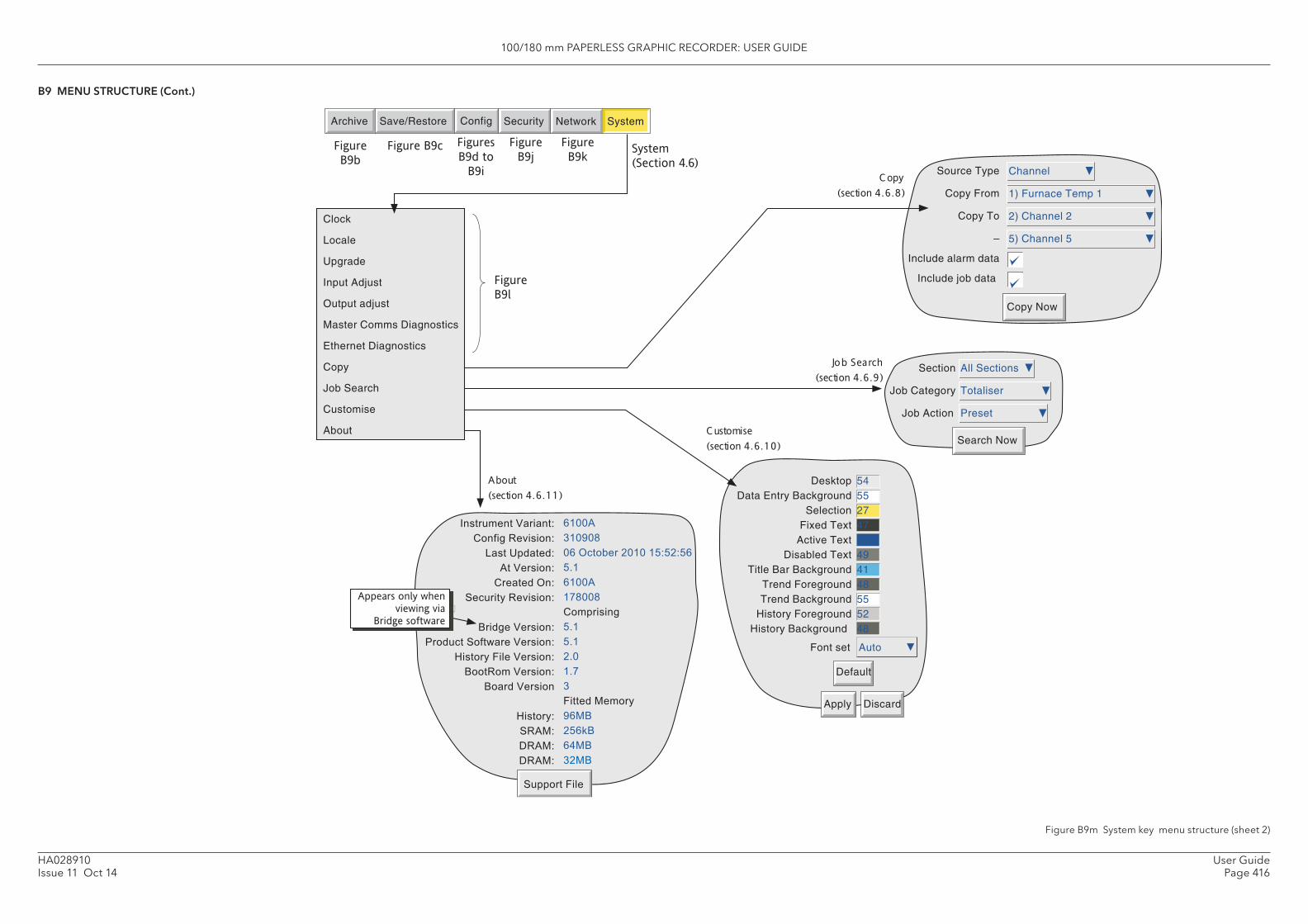
100/180 mm PAPERLESS GRAPHIC RECORDER: USER GUIDE
User GuidePage 416
HA028910Issue 11 Oct 14
Desktop Data Entry Background
Selection Fixed Text
Active Text Disabled Text
Title Bar Background Trend Foreground Trend Background
History Foreground History Background
54 55 27 47 6 49 41 48 55 52 48
Font set Auto
Default
Apply Discard
System (Section 4.6)
Copy Now
Source Type
Copy From
Copy To
Include alarm data
Include job data
Channel
1) Furnace Temp 1
2) Channel 2
5) Channel 5
Figure B9b
Archive SystemSave/Restore Config Security Network
Figure B9c Figures B9d to
B9i
Figure B9j
Figure B9k
Figure B9l
Search Now
All Sections
Totaliser
Preset
Section
Job Category
Job Action
.
Clock Locale Upgrade Input Adjust Output adjust Master Comms Diagnostics Ethernet Diagnostics Copy Job Search Customise About
Copy (section 4 .6 .8)
Customise (section 4 .6 .10)
Job Search (section 4 .6 .9)
About (section 4 .6 .11)
Appears only when viewing via
Bridge software
B9 MENU STRUCTURE (Cont.)
Figure B9m System key menu structure (sheet 2)

100/180 mm PAPERLESS GRAPHIC RECORDER: USER GUIDE
HA028910Issue 11 Oct 14
User GuidePage 417
This page is deliberately left blank
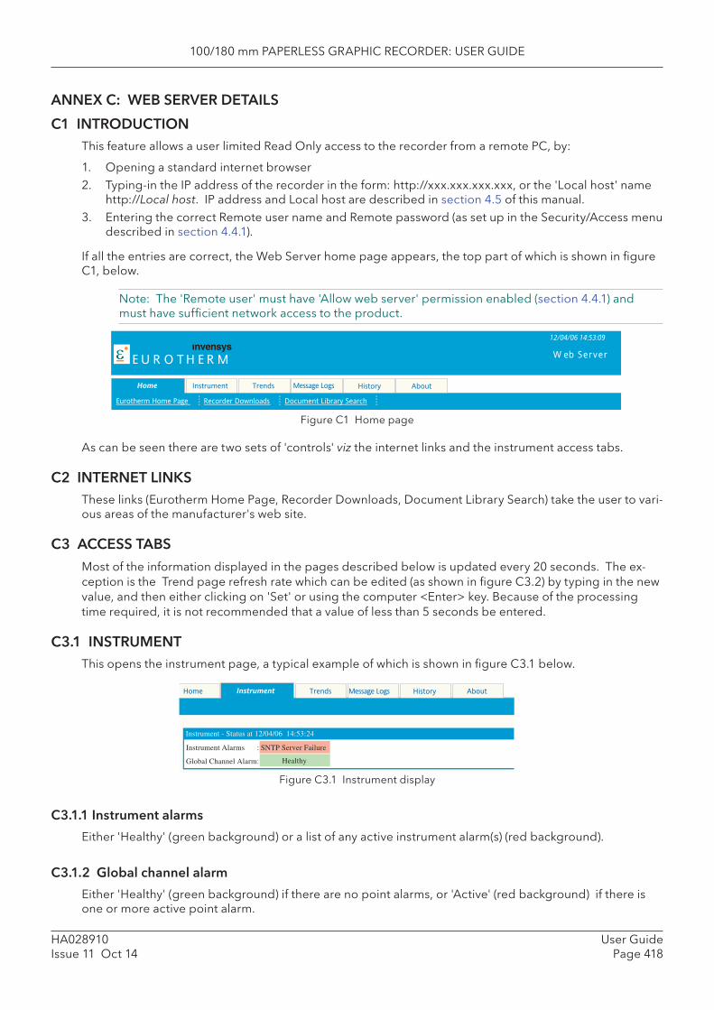
100/180 mm PAPERLESS GRAPHIC RECORDER: USER GUIDE
User GuidePage 418
HA028910Issue 11 Oct 14
ANNEX C: WEB SERVER DETAILS
C1 INTRODUCTIONThis feature allows a user limited Read Only access to the recorder from a remote PC, by:
1. Opening a standard internet browser2. Typing-in the IP address of the recorder in the form: http://xxx.xxx.xxx.xxx, or the 'Local host' name
http://Local host. IP address and Local host are described in section 4.5 of this manual.3. Entering the correct Remote user name and Remote password (as set up in the Security/Access menu
described in section 4.4.1).
If all the entries are correct, the Web Server home page appears, the top part of which is shown in fi gure C1, below.
Note: The 'Remote user' must have 'Allow web server' permission enabled (section 4.4.1) and must have suffi cient network access to the product.
Figure C1 Home page
As can be seen there are two sets of 'controls' viz the internet links and the instrument access tabs.
C2 INTERNET LINKSThese links (Eurotherm Home Page, Recorder Downloads, Document Library Search) take the user to vari-ous areas of the manufacturer's web site.
C3 ACCESS TABS
Most of the information displayed in the pages described below is updated every 20 seconds. The ex-ception is the Trend page refresh rate which can be edited (as shown in fi gure C3.2) by typing in the new value, and then either clicking on 'Set' or using the computer <Enter> key. Because of the processing time required, it is not recommended that a value of less than 5 seconds be entered.
C3.1 INSTRUMENTThis opens the instrument page, a typical example of which is shown in fi gure C3.1 below.
Home Instrument Trends Message Logs About
ε E U R O T H E R M
History
Eurotherm Home Page Recorder Downloads Document Library Search
12/04/06 14:53:09
W eb Server
Instrument AboutHistoryMessage Logs Trends Home
Instrument - Status at 12/04/06 14:53:24
Instrument Alarms :
Global Channel Alarm:
SNTP Server Failure
Healthy
Figure C3.1 Instrument display
C3.1.1 Instrument alarms
Either 'Healthy' (green background) or a list of any active instrument alarm(s) (red background).
C3.1.2 Global channel alarm
Either 'Healthy' (green background) if there are no point alarms, or 'Active' (red background) if there is one or more active point alarm.
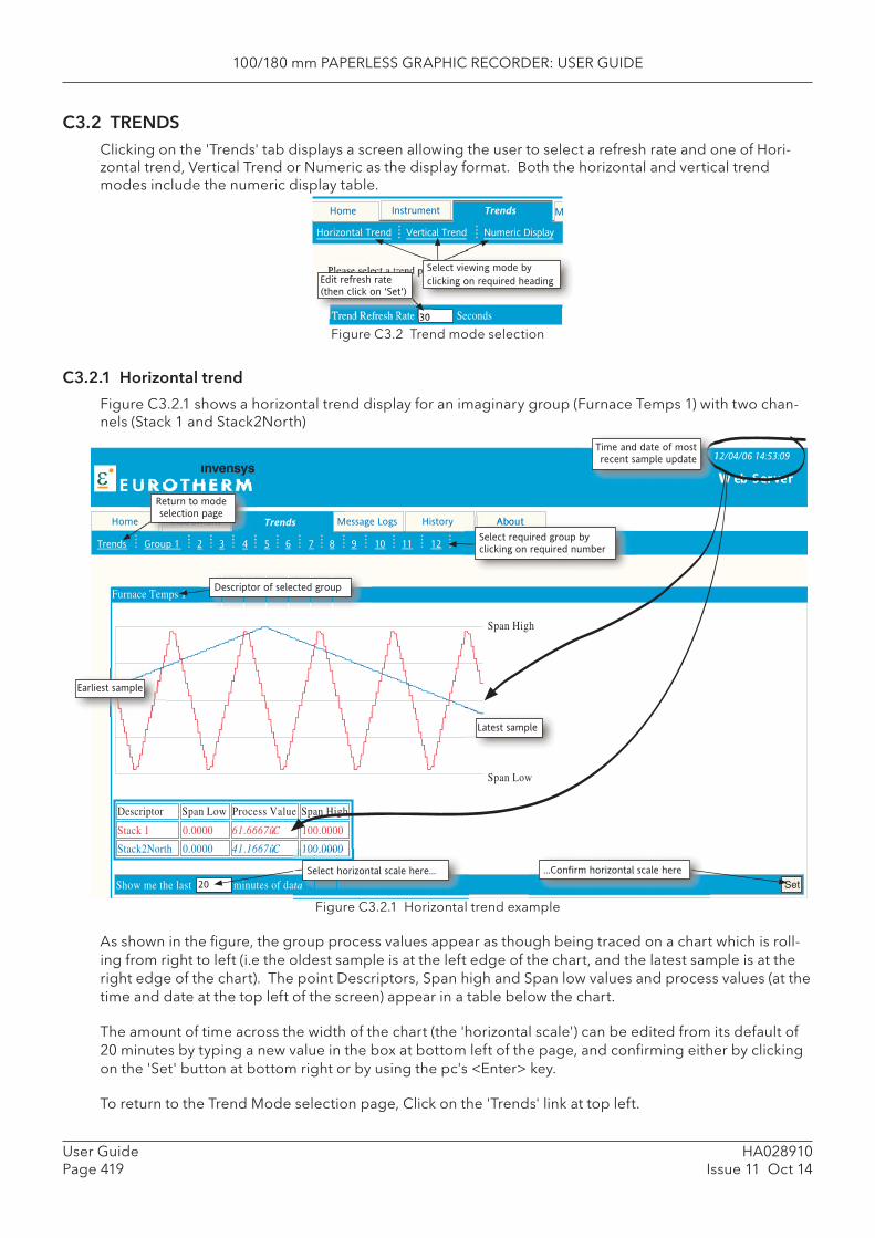
100/180 mm PAPERLESS GRAPHIC RECORDER: USER GUIDE
HA028910Issue 11 Oct 14
User GuidePage 419
Message Logs About
ε E U R O T H E R M
History
Trends
12/04/06 14:53:09
W eb Server
Home Trends
Group 1 2 3 4 5 6 7 8 9 10 11 12
Span Low
0.0000
0.0000
Process Value Span High
100.0000
100.0000
Descriptor
Stack 1
Stack2North
Furnace Temps 1
Show me the last minutes of data 20
Span High
Span Low
Select required group by clicking on required number
Descriptor of selected group
Select horizontal scale here...Set
...Confirm horizontal scale here
Time and date of most recent sample update
Earliest sample
Latest sample
Return to mode selection page
C3.2 TRENDSClicking on the 'Trends' tab displays a screen allowing the user to select a refresh rate and one of Hori-zontal trend, Vertical Trend or Numeric as the display format. Both the horizontal and vertical trend modes include the numeric display table.
Figure C3.2 Trend mode selection
C3.2.1 Horizontal trend
Figure C3.2.1 shows a horizontal trend display for an imaginary group (Furnace Temps 1) with two chan-nels (Stack 1 and Stack2North)
Figure C3.2.1 Horizontal trend example
As shown in the fi gure, the group process values appear as though being traced on a chart which is roll-ing from right to left (i.e the oldest sample is at the left edge of the chart, and the latest sample is at the right edge of the chart). The point Descriptors, Span high and Span low values and process values (at the time and date at the top left of the screen) appear in a table below the chart.
The amount of time across the width of the chart (the 'horizontal scale') can be edited from its default of 20 minutes by typing a new value in the box at bottom left of the page, and confi rming either by clicking on the 'Set' button at bottom right or by using the pc's <Enter> key.
To return to the Trend Mode selection page, Click on the 'Trends' link at top left.
Trend Refresh Rate Seconds
Home Instrument Trends M
Horizontal Trend Vertical Trend Numeric Display
Please select a trend page for viewing
30
Edit refresh rate
(then click on 'Set')
Select viewing mode by
clicking on required heading
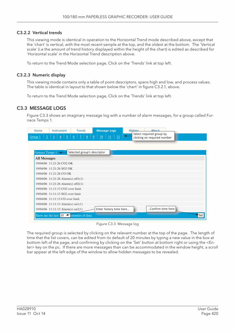
100/180 mm PAPERLESS GRAPHIC RECORDER: USER GUIDE
User GuidePage 420
HA028910Issue 11 Oct 14
C3.2.2 Vertical trends
This viewing mode is identical in operation to the Horizontal Trend mode described above, except that the 'chart' is vertical, with the most recent sample at the top, and the oldest at the bottom. The 'Vertical scale' (i.e the amount of trend history displayed within the height of the chart) is edited as described for 'Horizontal scale' in the Horizontal Trend description above.
To return to the Trend Mode selection page, Click on the 'Trends' link at top left.
C3.2.3 Numeric display
This viewing mode contains only a table of point descriptors, spans high and low, and process values. The table is identical in layout to that shown below the 'chart' in fi gure C3.2.1, above.
To return to the Trend Mode selection page, Click on the 'Trends' link at top left.
C3.3 MESSAGE LOGSFigure C3.3 shows an imaginary message log with a number of alarm messages, for a group called Fur-nace Temps 1.
Show me the last minutes of data 20 Set
Instrument HistoryHome Trends Message Logs
Group 1 2 3 4 5 6 7 8 9 10 11 12
Furnace Temps 1
All Messages19/04/06 11:21:26 CO2 OK
19/04/06 11:21:26 SO2 OK
19/04/06 11:21:26 CO OK
19/04/06 11:21:26 Alarm(s) off1(1)
19/04/06 11:21:26 Alarm(s) off2(1)
19/04/06 11:11:13 CO2 over limit
19/04/06 11:11:13 SO2 over limit
19/04/06 11:11:13 CO over limit
19/04/06 11:11:13 Alarm(s) on1(1)
19/04/06 11:11:13 Alarm(s) on2(1) Enter history time here... ...Confirm time here
Select required group by
clicking on required number
Selected group's descriptor
Figure C3.3 Message log
The required group is selected by clicking on the relevant number at the top of the page. The length of time that the list covers, can be edited from its default of 20 minutes by typing a new value in the box at bottom left of the page, and confi rming by clicking on the 'Set' button at bottom right or using the <En-ter> key on the pc. If there are more messages than can be accommodated in the window height, a scroll bar appear at the left edge of the window to allow hidden messages to be revealed.
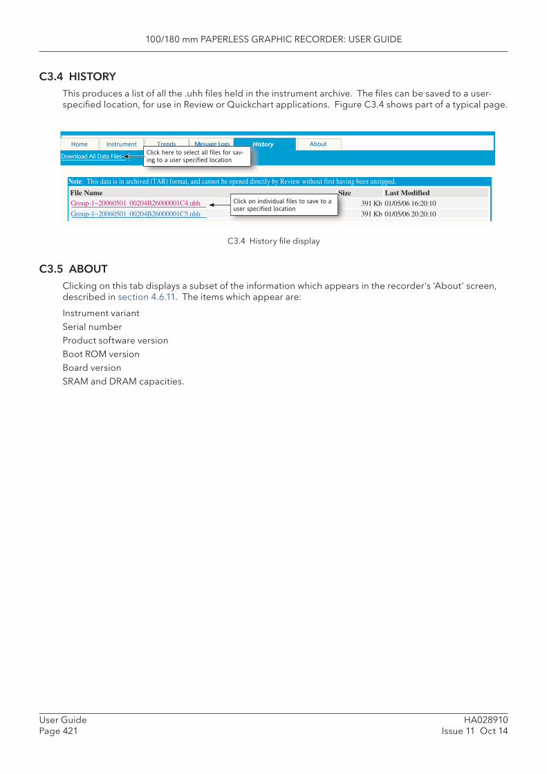
100/180 mm PAPERLESS GRAPHIC RECORDER: USER GUIDE
HA028910Issue 11 Oct 14
User GuidePage 421
C3.4 HISTORYThis produces a list of all the .uhh fi les held in the instrument archive. The fi les can be saved to a user-specifi ed location, for use in Review or Quickchart applications. Figure C3.4 shows part of a typical page.
History
Download All Data Files
Note: This data is in archived (TAR) format, and cannot be opened directly by Review without first having been unzipped.
Size Last Modified
391 Kb 01/05/06 16:20:10
391 Kb 01/05/06 20:20:10
Home Instrument About
File NameGroup-1~20060501 00204B26000001C4.uhh
Group-1~20060501 00204B26000001C5.uhh
Click here to select all files for sav-
ing to a user specified location
Click on individual files to save to a
user specified location
C3.4 History fi le display
C3.5 ABOUTClicking on this tab displays a subset of the information which appears in the recorder's 'About' screen, described in section 4.6.11. The items which appear are:
Instrument variantSerial numberProduct software versionBoot ROM versionBoard versionSRAM and DRAM capacities.
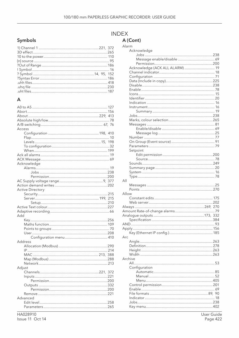
100/180 mm PAPERLESS GRAPHIC RECORDER: USER GUIDE
User GuidePage 422
HA028910Issue 11 Oct 14
INDEXA (Cont)Alarm
AcknowledgeJobs ........................................................................238Message enable/disable ....................................... 69Permission ..............................................................200
Acknowledge (ACK ALL ALARM) ................................ 19Channel indicator........................................................... 18Confi guration ................................................................. 71Data (Include in copy) ..................................................225Disable ...........................................................................238Enable .............................................................................. 78Icons ................................................................................. 15Identifi er .......................................................................... 20Indication ........................................................................ 16Instrument ....................................................................... 16
Summary .................................................................. 19Jobs ................................................................................238Marks, colour selection ...............................................265Messages ........................................................................ 81
Enable/disable ........................................................ 69Message log ............................................................ 25
Number ........................................................................... 77On Group (Event source) .............................................. 91Parameters ...................................................................... 79Setpoint
Edit permission .....................................................200Source ....................................................................... 78
Sounds ........................................................................... 249Summary page ............................................................... 20System ............................................................................. 16Type .................................................................................. 78
AllMessages ........................................................................ 25Points .............................................................................270
AllowConstant edits .............................................................. 175Web server ....................................................................202
Always ..........................................................................269, 270Amount Rate-of-change alarms .......................................... 79Analogue outputs ......................................................173, 332
Specifi cation .................................................................384AND ......................................................................................... 93Apply .....................................................................................156
Key (Ethernet IP confi g.) ..............................................185Arc
Angle ..............................................................................263Defi nition .......................................................................278Height ............................................................................263Width .............................................................................263
ArchiveAll ...................................................................................... 53Confi guration
Automatic ................................................................. 85Manual ...................................................................... 52Menu .......................................................................405
Control permission ......................................................201Enable .............................................................................. 69File formats ..............................................................89, 90Indicator .......................................................................... 18Jobs ................................................................................238Key menu .......................................................................402
Symbols1) Channel 1 ................................................................221, 3723D effect ...............................................................................26510 to the power .................................................................... 110{n} source ................................................................................ 95?Out of Range ......................................................................186! Symbol .................................................................................. 16? Symbol .................................................................14, 95, 152?Syntax Error ........................................................................186.uhh fi les ................................................................................ 418.uhq fi le .................................................................................230.uht fi les ................................................................................. 187
AA0 to A5 ................................................................................ 127Abort .....................................................................................156About ...........................................................................229, 413Absolute high/low ................................................................. 78A/B switching .................................................................. 67, 76Access
Confi guration ......................................................198, 410Flap ................................................................................... 10Levels ......................................................................15, 198To confi guration ............................................................. 32When ..............................................................................199
Ack all alarms ......................................................................... 19ACK Message ......................................................................... 69Acknowledge
Alarms .............................................................................. 19Jobs ........................................................................238Permission ..............................................................200
AC Supply voltage range .............................................. 9, 377Action demand writes ........................................................202Active Directory
Security .......................................................................... 215Server ....................................................................199, 215
Setup....................................................................... 210Active Text colour................................................................227Adaptive recording ...............................................................66Add
Key ..................................................................................256Maths function ..............................................................109Points to groups ............................................................. 70User ................................................................................208
Confi guration menu ............................................. 410Address
Allocation (Modbus) ....................................................290IP ..................................................................................... 214MAC ..................................................................... 213, 388Map (Modbus) ..............................................................288Network ......................................................................... 213
AdjustChannels ...............................................................221, 372Inputs .............................................................................221
Permission ..............................................................200Outputs .........................................................................332
Permission ..............................................................200Remove ..........................................................................221
AdvancedEdit level ........................................................................258Parameters ....................................................................265
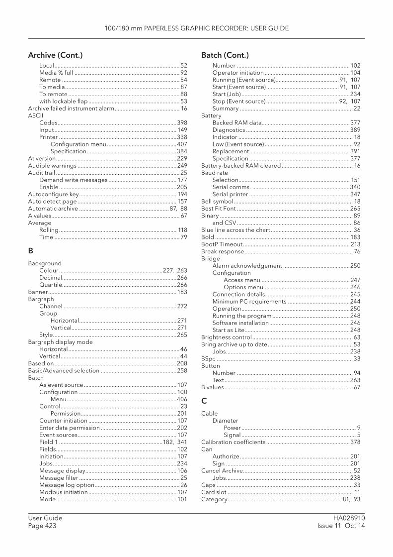
100/180 mm PAPERLESS GRAPHIC RECORDER: USER GUIDE
HA028910Issue 11 Oct 14
User GuidePage 423
Local ................................................................................. 52Media % full .................................................................... 92Remote ............................................................................54To media .......................................................................... 87To remote ........................................................................88with lockable fl ap ........................................................... 53
Archive failed instrument alarm .......................................... 16ASCII
Codes .............................................................................398Input ............................................................................... 149Printer ............................................................................338
Confi guration menu .............................................407Specifi cation ..........................................................384
At version ..............................................................................229Audible warnings ................................................................ 249Audit trail ................................................................................ 25
Demand write messages ............................................ 177Enable ............................................................................205
Autoconfi gure key ............................................................... 194Auto detect page ................................................................ 157Automatic archive .......................................................... 87, 88A values ................................................................................... 67Average
Rolling ............................................................................ 118Time ................................................................................. 79
BBackground
Colour ...................................................................227, 263Decimal ..........................................................................266Quartile..........................................................................266
Banner ...................................................................................183Bargraph
Channel .........................................................................272Group
Horizontal ............................................................... 271Vertical.................................................................... 271
Style................................................................................265Bargraph display mode
Horizontal ........................................................................46Vertical .............................................................................44
Based on ...............................................................................208Basic/Advanced selection .................................................258Batch
As event source ............................................................ 107Confi guration ...............................................................100
Menu .......................................................................406Control ............................................................................. 23
Permission ..............................................................201Counter initiation ......................................................... 107Enter data permission .................................................202Event sources ................................................................ 107Field 1 ...................................................................182, 341Fields ..............................................................................102Initiation ......................................................................... 107Jobs ................................................................................234Message display ...........................................................106Message fi lter ................................................................. 25Message log option ....................................................... 26Modbus initiation ......................................................... 107Mode .............................................................................. 101
Number .........................................................................102Operator initiation .......................................................104Running (Event source).........................................91, 107Start (Event source) ...............................................91, 107Start (Job) ......................................................................234Stop (Event source) ...............................................92, 107Summary ......................................................................... 22
BatteryBacked RAM data .........................................................377Diagnostics ...................................................................389Indicator .......................................................................... 18Low (Event source) ......................................................... 92Replacement .................................................................391Specifi cation .................................................................377
Battery-backed RAM cleared .............................................. 16Baud rate
Selection........................................................................ 151Serial comms. ...............................................................340Serial printer .................................................................347
Bell symbol ............................................................................. 18Best Fit Font .........................................................................265Binary ...................................................................................... 89
and CSV ...........................................................................86Blue line across the chart ..................................................... 36Bold .......................................................................................183BootP Timeout ..................................................................... 213Break response ...................................................................... 76Bridge
Alarm acknowledgement ...........................................250Confi guration
Access menu ......................................................... 247Options menu .......................................................246
Connection details ......................................................245Minimum PC requirements ........................................244Operation ......................................................................250Running the program ..................................................248Software installation ....................................................246Start as Lite ....................................................................248
Brightness control .................................................................63Bring archive up to date ....................................................... 53
Jobs ................................................................................238BSpc ........................................................................................ 33Button
Number ........................................................................... 94Text .................................................................................263
B values ................................................................................... 67
CCable
DiameterPower .......................................................................... 9Signal .......................................................................... 5
Calibration coeffi cients ......................................................378Can
Authorize .......................................................................201Sign ................................................................................201
Cancel Archive ....................................................................... 52Jobs ................................................................................238
Caps ........................................................................................ 33Card slot ................................................................................. 11Category ..........................................................................81, 93
Archive (Cont.) Batch (Cont.)
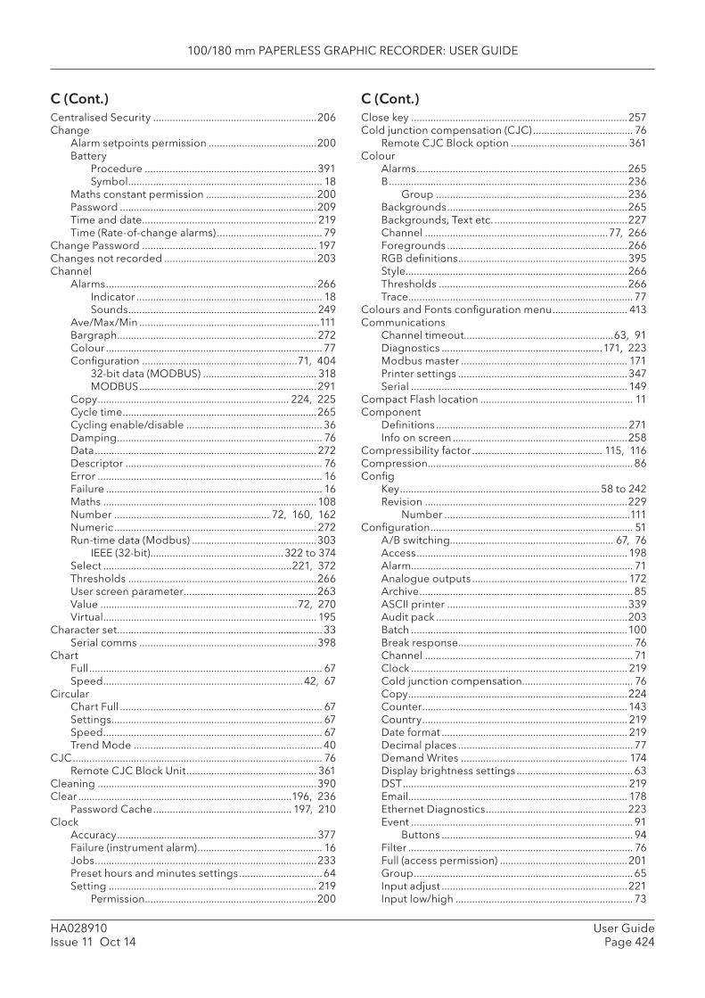
100/180 mm PAPERLESS GRAPHIC RECORDER: USER GUIDE
User GuidePage 424
HA028910Issue 11 Oct 14
C (Cont.) C (Cont.)Centralised Security ...........................................................206Change
Alarm setpoints permission .......................................200Battery
Procedure ..............................................................391Symbol ...................................................................... 18
Maths constant permission ........................................200Password .......................................................................209Time and date ............................................................... 219Time (Rate-of-change alarms) ...................................... 79
Change Password ............................................................... 197Changes not recorded .......................................................203Channel
Alarms ............................................................................266Indicator ................................................................... 18Sounds .................................................................... 249
Ave/Max/Min .................................................................111Bargraph ........................................................................272Colour .............................................................................. 77Confi guration ........................................................71, 404
32-bit data (MODBUS) ......................................... 318MODBUS ................................................................291
Copy ..................................................................... 224, 225Cycle time ......................................................................265Cycling enable/disable ................................................. 36Damping .......................................................................... 76Data ................................................................................272Descriptor ....................................................................... 76Error ................................................................................. 16Failure .............................................................................. 16Maths .............................................................................108Number ........................................................ 72, 160, 162Numeric .........................................................................272Run-time data (Modbus) .............................................303
IEEE (32-bit) ................................................322 to 374Select ....................................................................221, 372Thresholds ....................................................................266User screen parameter ................................................263Value .......................................................................72, 270Virtual ............................................................................. 195
Character set .......................................................................... 33Serial comms ................................................................398
ChartFull .................................................................................... 67Speed ........................................................................42, 67
CircularChart Full ......................................................................... 67Settings ............................................................................ 67Speed ............................................................................... 67Trend Mode ....................................................................40
CJC .......................................................................................... 76Remote CJC Block Unit ............................................... 361
Cleaning ...............................................................................390Clear .............................................................................196, 236
Password Cache .................................................. 197, 210Clock
Accuracy ........................................................................377Failure (instrument alarm) ............................................. 16Jobs ................................................................................233Preset hours and minutes settings ..............................64Setting ........................................................................... 219
Permission ..............................................................200
Close key ..............................................................................257Cold junction compensation (CJC) .................................... 76
Remote CJC Block option .......................................... 361Colour
Alarms ............................................................................265B ......................................................................................236
Group .....................................................................236Backgrounds .................................................................265Backgrounds, Text etc. ................................................227Channel ..................................................................77, 266Foregrounds .................................................................266RGB defi nitions .............................................................395Style................................................................................266Thresholds ....................................................................266Trace ................................................................................. 77
Colours and Fonts confi guration menu ........................... 413Communications
Channel timeout......................................................63, 91Diagnostics ..........................................................171, 223Modbus master ............................................................ 171Printer settings .............................................................347Serial .............................................................................. 149
Compact Flash location ....................................................... 11Component
Defi nitions ..................................................................... 271Info on screen ...............................................................258
Compressibility factor ............................................... 115, 116Compression ..........................................................................86Confi g
Key ........................................................................58 to 242Revision .........................................................................229
Number ...................................................................111Confi guration ......................................................................... 51
A/B switching........................................................... 67, 76Access ............................................................................ 198Alarm ................................................................................ 71Analogue outputs ........................................................ 172Archive ............................................................................. 85ASCII printer .................................................................339Audit pack .....................................................................203Batch ..............................................................................100Break response ............................................................... 76Channel ........................................................................... 71Clock .............................................................................. 219Cold junction compensation........................................ 76Copy ...............................................................................224Counter ..........................................................................143Country .......................................................................... 219Date format ................................................................... 219Decimal places ............................................................... 77Demand Writes ............................................................ 174Display brightness settings ..........................................63DST ................................................................................. 219Email............................................................................... 178Ethernet Diagnostics ...................................................223Event ................................................................................ 91
Buttons ..................................................................... 94Filter ................................................................................. 76Full (access permission) ..............................................201Group ............................................................................... 65Input adjust ...................................................................221Input low/high ................................................................ 73
100/180 mm PAPERLESS GRAPHIC RECORDER: USER GUIDE
HA028910Issue 11 Oct 14
User GuidePage 425
Confi guration (Cont.) Counter (Cont.)Instrument .......................................................................63Language ...................................................................... 219Linearisation
Range ........................................................................ 73Type .......................................................................... 72
Locale............................................................................. 219Locked icon ..................................................................... 18Management option ....................................................203Master comms .............................................................. 153Maths channels .............................................................108Menu ................................................................. 404 to 409Message .......................................................................... 95Network ......................................................................... 213Offset ............................................................................... 73Options .............................................................. 194 to 196Output Channel
Analogue outputs ................................................. 173Master comms ....................................................... 172
Printer comms parameters .........................................346Reports .................................................................182, 341Scale ................................................................................. 73Security .......................................................................... 197Serial communications ................................................ 150Shunt value ...................................................................... 73Span ................................................................................. 77Summertime ................................................................. 219System ........................................................................... 217Time and date ............................................................... 219Timers ............................................................................ 147Time zone ...................................................................... 219Totaliser ......................................................................... 138Trace colour .................................................................... 77Upgrade ........................................................................220User linearisation tables................................................ 98Views ................................................................................ 82Zone
Area of chart ............................................................ 77Time ...............................................................219, 399
Connected messaging .......................................................184Connect from Remote permission ...................................199Connections ......................................................................... 149Connector locations
Large frame units ............................................................. 6Small frame units .............................................................. 5
Constant ...............................................................................109Contents of group ................................................................. 70Continuous batches ............................................................ 101Controller parameters ........................................................ 162Copy .............................................................................110, 224
Facility ...................................................................224, 413File ..................................................................................240Key ..................................................................................256Maths function .............................................................. 110Rules ...............................................................................225Screen ............................................................................257To/From .........................................................................225
CounterBatch initiation .............................................................. 107Confi guration ...............................................................143
Data (Modbus) .......................................................144IEEE 32-bit .......................................................145
Confi guration menu ....................................................406Copy ...............................................................................225Enable ............................................................................143Jobs ................................................................................233Modbus addressing
Confi guration ........................................................144IEEE (32-bit) ....................................................146
Runtime data ......................................................... 145Number .........................................................................143Preset permission ........................................................200
Country, Selection of .......................................................... 219Created on ...........................................................................229Creating a user screen........................................................254CSV ..........................................................................................86
Date/time format ............................................................90Files .................................................................................. 89Format ............................................................................. 89Use tab delimiter ............................................................ 89
Currently ... ........................................................................... 194Cursor keys ............................................................................. 28Custom Faceplate style ...................................................... 267Customise .............................................................................227
Confi guration menu .................................................... 413Cut fi le ...................................................................................240Cutoff (High/Low) ................................................................ 138Cycle channels on/off ........................................................... 36
DDaily .................................................................................. 87, 88Data
BitsPrinter .....................................................................347Serial Comms ........................................................ 151
Compression Ratio ........................................................86Encoding (MODBUS) ...................................................281Entry Background colour ............................................227Source ............................................................................ 173Transmission (MODBUS) .............................................328Type .......................................................................164, 281
Demand writes ...................................................... 176Date and time ......................................................................341
Confi guration ...................................................... 219, 412CSV format ......................................................................90Reports confi guration .................................................182
Daylight saving confi guration ........................................... 219DC supply
Printer wiring ................................................................338Recorder wiring ................................................................ 9
Decimal ................................................................................. 187Places .............................................................77, 177, 266
EtherNet/IP ............................................................ 187Scale ...............................................................................269
Decrement counter .............................................................233Default .................................................................................. 172
Demand Write value .................................................... 175Gateway ......................................................................... 214Passwords ....................................................................... 31
Default Table ........................................................................185Delete key
File ..................................................................................240User Screens .................................................................256
100/180 mm PAPERLESS GRAPHIC RECORDER: USER GUIDE
User GuidePage 426
HA028910Issue 11 Oct 14
D (Cont.) D (Cont.)Demand
Type ................................................................................ 175Writes ............................................................................. 174
Action permission ................................................202Button ..................................................................... 175Confi guration menu .............................................408Copy .......................................................................225Jobs ........................................................................237To specifi c register ............................................... 176With Audit Trail...................................................... 177
Deploy ...................................................................................257Descriptor
Channel ........................................................................... 76Demand write ............................................................... 175Email Recipient list ....................................................... 179Event ................................................................................ 93Event Button ................................................................... 94Font ................................................................................ 267Group ........................................................................15, 66Group minimum maths function................................ 132Instrument .......................................................................63Minimum Channel ........................................................ 132Output channel ...................................................172, 173Report ...................................................................182, 341Slave device .................................................................. 155Timer ..............................................................................148User Linearisation table ................................................ 98
DetectAll slaves ........................................................................156This slave ....................................................................... 155
DeviationAlarm type....................................................................... 78Value ................................................................................ 79
DHCP Server failure .............................................................. 16Diagnostics
Display ...........................................................................385Ethernet .........................................................................223Master comms .............................................................. 171Summary .......................................................................388
Dialogue action ...................................................................272Digital ...........................................................................160, 162Disable
Alarms ............................................................................238Counter ..........................................................................233Display
Alarms..................................................................... 267Descriptor .............................................................. 267Messages ............................................................... 267Pens ......................................................................... 267Units ........................................................................ 267
Group counters ............................................................233Group totalisers ............................................................231Login ..............................................................................200Maths Function .............................................................232Retries ............................................................................ 175Timer job .......................................................................234Totaliser .........................................................................231Warning dialogs .............................................................64
Disabled Text colour ...........................................................227Discard ..................................................................................156
Ethernet IP Table ..........................................................185Key ..................................................................................257
DiskSize ................................................................................... 87Symbol ............................................................................. 18
DisplayAlarms ............................................................................ 267Bargraph ........................................................................ 267Batch Dialogue ............................................................. 107Brightness .......................................................................63Calibration ....................................................................386Colour confi guration menu ........................................ 413Descriptor ..................................................................... 267Enable (group) ................................................................83Home ............................................................................... 82Messages ...................................................................... 267Modes .............................................................................. 35
Circular trend ..........................................................40Enable .......................................................................83Home ........................................................................ 82Horizontal bargraph ...............................................46Horizontal trend ...................................................... 38Numeric ....................................................................48Select ........................................................................ 28Vertical bargraph ....................................................44Vertical trend ........................................................... 36
Pens ................................................................................ 267Test .................................................................................386Units ............................................................................... 267Update rate ...................................................................377Values (truncation of) .................................................... 14
Dispose .................................................................................257Divide ....................................................................................109DNS ....................................................................................... 216Domain name
Access menu .................................................................199Domain Name Service ........................................................ 216Do Not Remove Archive Media ........................................... 13Draw
Edge ...............................................................................263Order .............................................................................263
Drive Relay job .....................................................................231Dry bulb temperature ......................................................... 127Dryness ................................................................................. 120DST ........................................................................................ 219D-type connector wiring ........................................................ 9Duration ................................................................................148Dwell ....................................................................................... 79
EEarlier messages.. ................................................................. 26Edit
Level ...............................................................................258Maths constant permission ........................................200Output channel default ...............................................201Own password permission .........................................200Parameter ......................................................................263
EIA232 / EIA485 selection ................................................. 151Elapsed time format ............................................................ 112Electrical installation............................................................... 5Email
Access ............................................................................ 181Appearance ..................................................................180
100/180 mm PAPERLESS GRAPHIC RECORDER: USER GUIDE
HA028910Issue 11 Oct 14
User GuidePage 427
Email (Cont.) Event (Cont.)Confi guration ............................................................... 178
Menu .......................................................................409Failure .............................................................................. 92Generation ...........................................................180, 181Jobs ................................................................................239Messages ...................................................................... 181Number ......................................................................... 179
Emphasised ..........................................................................183Enable
Alarm ................................................................................ 78Audit trail .......................................................................205Batch .............................................................................. 101Counter ..........................................................................143Demand writes ............................................................. 175Display
Alarms..................................................................... 267Descriptor .............................................................. 267Messages ............................................................... 267Modes .......................................................................83Pens ......................................................................... 267Units ........................................................................ 267
Error code B .................................................................. 152EUROPRP Server .......................................................... 215Modbus Slave ............................................................... 155Options ..........................................................................394Output channel ...................................................172, 173Recording ......................................................................235Remote device .............................................................. 155SNTP Server .................................................................. 214Talk through .................................................................. 152Timer ..............................................................................148Totaliser ......................................................................... 138
End of message characters ............................................... 151Engineer, Access level .................................................31, 198Enter batch data (permission) ...........................................202Enter history ........................................................................... 35
Message log option ....................................................... 26Erase all history.................................................................... 196
Job .................................................................................235Option ............................................................................400
ErrorCode B enable .............................................................. 152Messages
Bridge ..................................................................... 251User screens ..........................................................279
Errors To (Email confi guration) .......................................... 179EtherNet
Address .........................................................................388Diagnostics ..........................................................223, 412LED interpretation .......................................................378Modbus Slave ............................................................... 155
EtherNet/IP ..........................................................................184Client ..............................................................................224Comms Input ................................................................109
e to the power .......................................................................111EUROPRP Server enable .................................................... 215Event
As event source .............................................................. 91Button ............................................................................263
As event sources ..................................................... 92Confi guration ................................................ 94, 405Size, shape etc. ......................................................273
Confi guration ........................................................91, 405Copy ...............................................................................225Input board
Specifi cation ..........................................................384Wiring ......................................................................... 8
Inputs .............................................................................334As event sources ..................................................... 92
Number ........................................................................... 91Permissions 1 to 5 ........................................................201Source .............................................................................. 91
Batch ....................................................................... 107Source sense ......................................................... 92 to 93
Exclamation mark symbol .................................................... 16Exit .........................................................................................372Explicit messaging .................................................... 184, 224Export
Ethernet table ...............................................................185Key ..................................................................................257Screen .............................................................................. 56User linearisation ........................................................... 57User screens..................................................................253
External CJ ............................................................................. 76
FFaceplates .............................................................................. 42
Location ......................................................................... 267Style................................................................................ 267
Failed to authenticate user name ..................................... 251Fast Settle .................................................221, 222, 372, 373Feature ..................................................................................263
Changed ........................................................................243Identifi cation table ....................................................... 315Locked ...........................................................................243
Fields 1 to 6Batch ..............................................................................102Type
Reports ...................................................................182Serial comms .........................................................341
File .........................................................................................240Delete ............................................................................240Format ............................................................................. 87
Media ........................................................................ 89Key .................................................................................... 28Name character limitation ............................................ 56Paste/delete permission .............................................201Structure ........................................................................242Transfer (FTP) facility .....................................................54
Filer option menu keys .......................................................240Fill Area .................................................................................263Filter ........................................................................................ 76First
Channel (Input adjust) .................................................221Start/End character ..................................................... 151Switch on ......................................................................... 31
First channel .........................................................................372FIT .......................................................................................... 315Fixed Text colour .................................................................227Flap, lockable ......................................................................... 12
Unlock permission .......................................................201Flash size .................................................................................86Flow ....................................................................................... 120
100/180 mm PAPERLESS GRAPHIC RECORDER: USER GUIDE
User GuidePage 428
HA028910Issue 11 Oct 14
Group (Cont.)F (Cont.)Folder keys ............................................................................. 28Font
Set ...................................................................................227Style................................................................................ 267
Force change of password ................................................202Foreground
Colour ...................................................................227, 264Decimal ..........................................................................266Quartile..........................................................................266
FormatPV ............................................................................. 77, 112User Lin. point pairs ....................................................... 98
For (nodes) ...........................................................................156Freeze ....................................................................................236From
Node ..............................................................................156Point .................................................................................68
From point ............................................................................ 187FTP
Error messages ............................................................... 16File format ................................................................ 87, 90Icon ................................................................................... 18Transfer ............................................................................54
FullConfi guration access ...................................................201Detail ................................................................................ 23Details (Message log) .................................................... 26Screen (circular trends) ................................................. 42Security ..........................................................................201User name .....................................................................208
Function code .............................................................164, 17603 ....................................................................................32904 ....................................................................................33006 ....................................................................................33008 ....................................................................................33016 ....................................................................................331
Fuse (Transmitter power supply) ............................ 335, 378FValue maths function ........................................................ 113
GGas constant ............................................................... 114, 116General message fi lter ......................................................... 25Global
Channel alarm .............................................................. 415Global alarm
Event source ................................................................... 91Unacknowledged ........................................................... 91
GotoCanvas ...........................................................................257Group ............................................................................... 29View .................................................................................. 28
Green line across the chart .................................................. 36Grid
Line colourMajor ....................................................................... 267Minor.......................................................................268
Type ..................................................................................68
GroupAdding points to ............................................................ 70Average/Minimum/Maximum ....................................109Confi guration ....................................................... 65, 404Copy ...............................................................................225Data (MODBUS) ............................................................309Descriptor ................................................................15, 66Display Mode enable ....................................................83Home ............................................................................... 82Horizontal Bargraph .................................................... 271Latched Maximum maths function ............................ 110Latched Minimum maths function ............................. 110Minimum........................................................................ 132MKT maths function .................................................... 124Number ...............................................66, 160, 175, 264Numeric display ...........................................................272Recording enable/disable ............................................68Report destination .......................................................239Selection for comms messages ................................. 151Trend .............................................................................. 271Vertical bargraph ......................................................... 271Views, Scope ...................................................................83
HHandshake ............................................................................347Hardware version ................................................................229Height....................................................................................264Hide key ................................................................................240High
Cutoff ............................................................................. 138Point ...............................................................................222Priority interval .............................................................154Select ............................................................................. 110
Highlight ................................................................................. 23High/Low .............................................................................. 177High Point .............................................................................373History ................................................................................... 418
Amount of ................................................................35, 69Background/Foreground colours .............................227
HomeGroup ............................................................................... 82Key .................................................................................... 28Page .................................................................................83Timout .............................................................................. 82
HorizontalAlignment ...................................................................... 267Bargraph .................................................................46, 269Faceplate .............................................................. 267, 269Grid total ....................................................................... 267Minor Divisions .............................................................268Trend display mode ....................................................... 38
Enable .......................................................................83User screens .......................................................... 271
Trend modeWeb server ............................................................. 416
Host .......................................................................................223Hourly ............................................................................... 87, 88HTM2010 Quarterly Test kit ...............................................353Hysteresis ............................................................................... 79
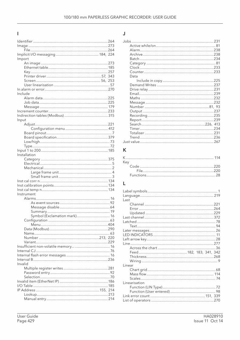
100/180 mm PAPERLESS GRAPHIC RECORDER: USER GUIDE
HA028910Issue 11 Oct 14
User GuidePage 429
IIdentifi er ...............................................................................264Image ....................................................................................273
File ..................................................................................264Implicit I/O messaging ............................................. 184, 224Import
An image .......................................................................273Ethernet table ...............................................................185Key ..................................................................................257Printer driver ..........................................................57, 343Screen .................................................................... 56, 253User linearisation ........................................................... 57
In alarm or error ...................................................................270Include
Alarm data .....................................................................225Job data .........................................................................225Message ........................................................................ 179
Increment counter ...............................................................233Indirection tables (Modbus) .............................................. 315Input
Adjust .............................................................................221Confi guration menu ............................................. 412
Board pinout ..................................................................... 7Board specifi cation ......................................................379Low/high .......................................................................... 73Type .................................................................................. 72
Input 1 to 200 .......................................................................185Installation
Category ....................................................................... 375Electrical ............................................................................ 5Mechanical ........................................................................ 2
Large frame unit ........................................................ 4Small frame unit ........................................................ 3
Inst cal corr n ........................................................................ 134Inst calibration points ......................................................... 134Inst cal temp n ...................................................................... 134Instrument
Alarms .............................................................................. 16As event sources ..................................................... 92Message disable .....................................................64Summary .................................................................. 19Symbol (Exclamation mark) ................................... 16
Confi guration .................................................................63Menu .......................................................................404
Data (Modbus) ..............................................................290Name ................................................................................63Number ................................................................213, 220Variant ............................................................................229
Insuffi cient non-volatile memory... ..................................... 16Internal CJ .............................................................................. 76Internal fl ash error messages .............................................. 16Interval B ...............................................................................236Invalid
Multiple register writes ...............................................281Password entry ............................................................... 92Selection.......................................................................... 70
Invalid item (EtherNet IP) ...................................................186I/O Table ...............................................................................185IP Address ...................................................................155, 214
Lookup ........................................................................... 213Manual entry ................................................................. 214
JJobs .......................................................................................231
Active while/on ............................................................... 81Alarm ..............................................................................238Archive ...........................................................................238Batch ..............................................................................234Category ......................................................................... 81Clock ..............................................................................233Counter ..........................................................................233Data
Include in copy ......................................................225Demand Writes ............................................................237Drive relay .....................................................................231Email...............................................................................239Maths .............................................................................232Message ........................................................................232Number ....................................................................81, 93Output ...........................................................................237Recording ......................................................................235Report ............................................................................239Search ...................................................................226, 413Timer ..............................................................................234Totaliser .........................................................................231Trend ..............................................................................236
Just value .............................................................................. 267
KK ............................................................................................. 114Key
Code ..............................................................................220File ...........................................................................220
Functions ......................................................................... 28
LLabel symbols .......................................................................... 1Language .............................................................................. 219Last
Channel .........................................................................221Error ...............................................................................264Updated ........................................................................229
Last channel .........................................................................372Latched ................................................................................... 78
Text ................................................................................... 94Later messages.. .................................................................... 26LED INDICATORS .................................................................. 11Left arrow key ......................................................................... 28Line ........................................................................................277
Across the chart ............................................................. 36Feed ...................................................182, 183, 341, 342Thickness .......................................................................268Wiring ................................................................................ 9
LinearChart grid ........................................................................68Mass fl ow ....................................................................... 114Scales ............................................................................... 74
LinearisationFunction (LIN Type) ........................................................ 72Function (User entered) ................................................ 98
Link error count ..........................................................151, 339List of operators ..................................................................270
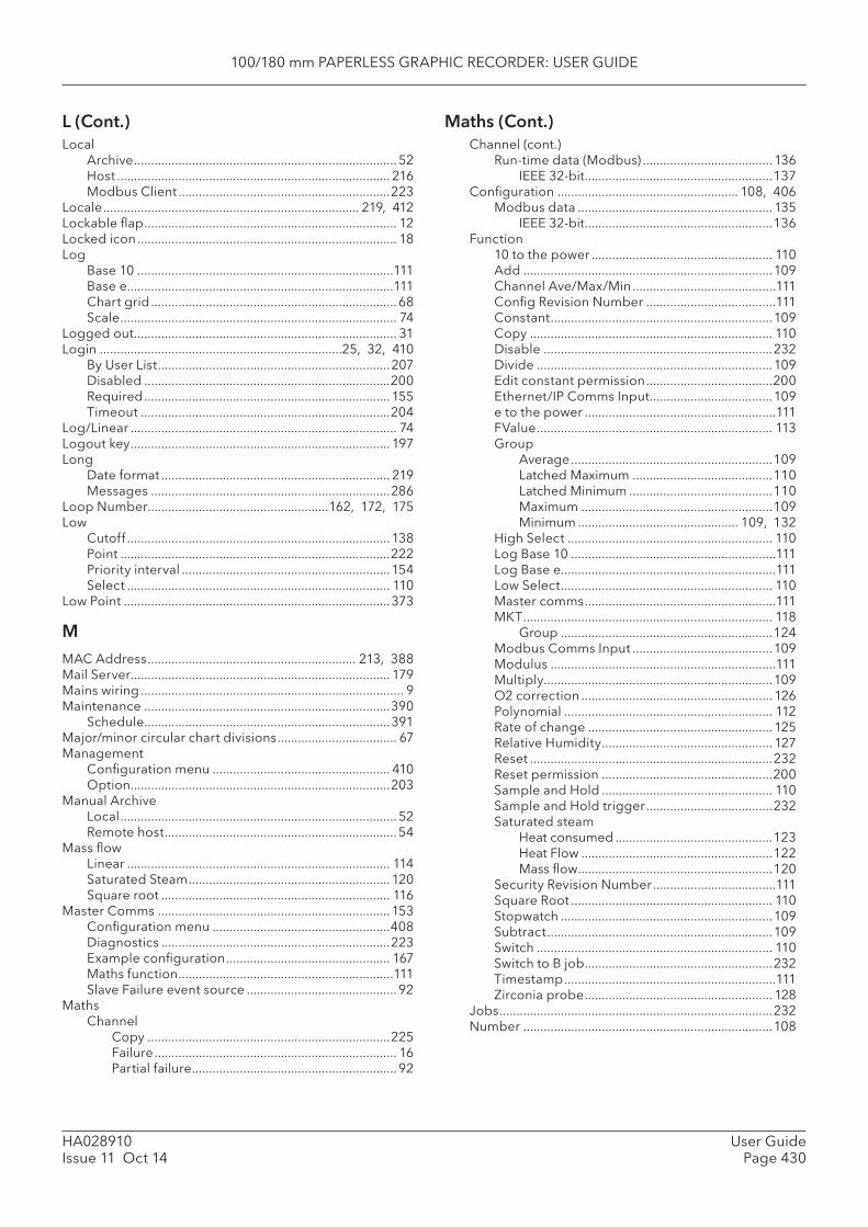
100/180 mm PAPERLESS GRAPHIC RECORDER: USER GUIDE
User GuidePage 430
HA028910Issue 11 Oct 14
Maths (Cont.)L (Cont.)Local
Archive ............................................................................. 52Host ................................................................................ 216Modbus Client ..............................................................223
Locale ........................................................................... 219, 412Lockable fl ap .......................................................................... 12Locked icon ............................................................................ 18Log
Base 10 ...........................................................................111Base e ..............................................................................111Chart grid ........................................................................68Scale ................................................................................. 74
Logged out ............................................................................. 31Login .......................................................................25, 32, 410
By User List ....................................................................207Disabled ........................................................................200Required ........................................................................ 155Timeout .........................................................................204
Log/Linear .............................................................................. 74Logout key ............................................................................ 197Long
Date format ................................................................... 219Messages ......................................................................286
Loop Number.....................................................162, 172, 175Low
Cutoff ............................................................................. 138Point ...............................................................................222Priority interval .............................................................154Select ............................................................................. 110
Low Point ..............................................................................373
MMAC Address ............................................................. 213, 388Mail Server............................................................................ 179Mains wiring ............................................................................. 9Maintenance ........................................................................390
Schedule ........................................................................391Major/minor circular chart divisions ................................... 67Management
Confi guration menu .................................................... 410Option ............................................................................203
Manual ArchiveLocal ................................................................................. 52Remote host ....................................................................54
Mass fl owLinear ............................................................................. 114Saturated Steam ........................................................... 120Square root ................................................................... 116
Master Comms .................................................................... 153Confi guration menu ....................................................408Diagnostics ...................................................................223Example confi guration ................................................ 167Maths function ...............................................................111Slave Failure event source ............................................ 92
MathsChannel
Copy .......................................................................225Failure ....................................................................... 16Partial failure ............................................................ 92
Channel (cont.)Run-time data (Modbus) ...................................... 136
IEEE 32-bit .......................................................137Confi guration ..................................................... 108, 406
Modbus data ......................................................... 135IEEE 32-bit .......................................................136
Function10 to the power ..................................................... 110Add .........................................................................109Channel Ave/Max/Min ..........................................111Confi g Revision Number ......................................111Constant .................................................................109Copy ....................................................................... 110Disable ...................................................................232Divide .....................................................................109Edit constant permission .....................................200Ethernet/IP Comms Input ....................................109e to the power ........................................................111FValue ..................................................................... 113Group
Average ...........................................................109Latched Maximum .........................................110Latched Minimum ..........................................110Maximum ........................................................109Minimum ............................................... 109, 132
High Select ............................................................ 110Log Base 10 ............................................................111Log Base e...............................................................111Low Select .............................................................. 110Master comms ........................................................111MKT ......................................................................... 118
Group ..............................................................124Modbus Comms Input .........................................109Modulus ..................................................................111Multiply ...................................................................109O2 correction ........................................................ 126Polynomial ............................................................. 112Rate of change ...................................................... 125Relative Humidity .................................................. 127Reset .......................................................................232Reset permission ..................................................200Sample and Hold .................................................. 110Sample and Hold trigger .....................................232Saturated steam
Heat consumed ..............................................123Heat Flow ........................................................122Mass fl ow .........................................................120
Security Revision Number ....................................111Square Root ........................................................... 110Stopwatch ..............................................................109Subtract ..................................................................109Switch ..................................................................... 110Switch to B job .......................................................232Timestamp ..............................................................111Zirconia probe ....................................................... 128
Jobs ................................................................................232Number .........................................................................108
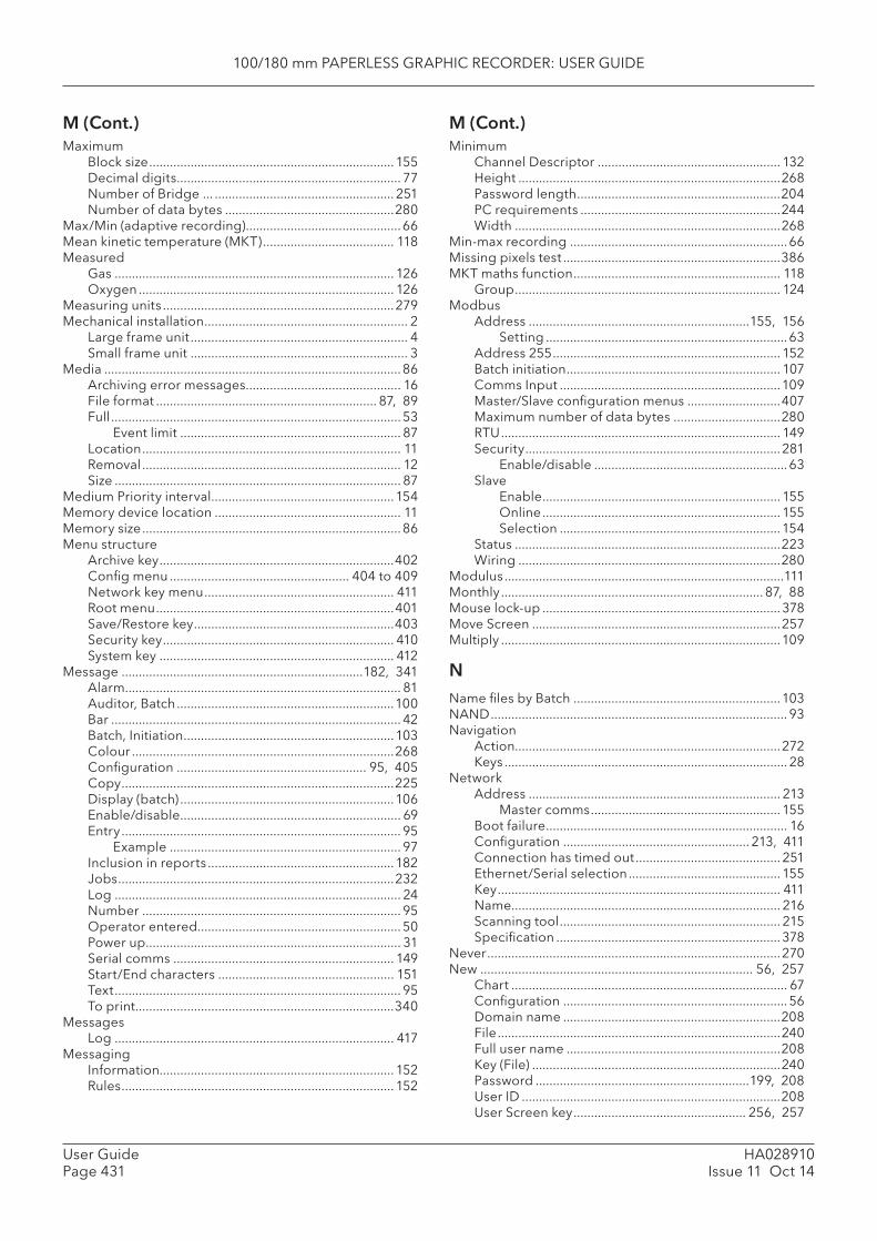
100/180 mm PAPERLESS GRAPHIC RECORDER: USER GUIDE
HA028910Issue 11 Oct 14
User GuidePage 431
M (Cont.)Maximum
Block size ....................................................................... 155Decimal digits ................................................................. 77Number of Bridge ... .................................................... 251Number of data bytes .................................................280
Max/Min (adaptive recording) .............................................66Mean kinetic temperature (MKT) ...................................... 118Measured
Gas ................................................................................. 126Oxygen .......................................................................... 126
Measuring units ...................................................................279Mechanical installation ........................................................... 2
Large frame unit ............................................................... 4Small frame unit ............................................................... 3
Media ......................................................................................86Archiving error messages ............................................. 16File format ................................................................ 87, 89Full .................................................................................... 53
Event limit ................................................................ 87Location ........................................................................... 11Removal ........................................................................... 12Size ................................................................................... 87
Medium Priority interval .....................................................154Memory device location ...................................................... 11Memory size ...........................................................................86Menu structure
Archive key ....................................................................402Confi g menu .................................................... 404 to 409Network key menu ....................................................... 411Root menu .....................................................................401Save/Restore key ..........................................................403Security key ................................................................... 410System key .................................................................... 412
Message ......................................................................182, 341Alarm ................................................................................ 81Auditor, Batch ...............................................................100Bar .................................................................................... 42Batch, Initiation .............................................................103Colour ............................................................................268Confi guration ....................................................... 95, 405Copy ...............................................................................225Display (batch) ..............................................................106Enable/disable ................................................................ 69Entry ................................................................................. 95
Example ................................................................... 97Inclusion in reports ......................................................182Jobs ................................................................................232Log ................................................................................... 24Number ........................................................................... 95Operator entered........................................................... 50Power up .......................................................................... 31Serial comms ................................................................ 149Start/End characters ................................................... 151Text ................................................................................... 95To print ...........................................................................340
MessagesLog ................................................................................. 417
MessagingInformation.................................................................... 152Rules ............................................................................... 152
MinimumChannel Descriptor ..................................................... 132Height ............................................................................268Password length ...........................................................204PC requirements ..........................................................244Width .............................................................................268
Min-max recording ...............................................................66Missing pixels test ...............................................................386MKT maths function ............................................................ 118
Group ............................................................................. 124Modbus
Address ................................................................155, 156Setting ......................................................................63
Address 255 .................................................................. 152Batch initiation .............................................................. 107Comms Input ................................................................109Master/Slave confi guration menus ...........................407Maximum number of data bytes ...............................280RTU ................................................................................. 149Security ..........................................................................281
Enable/disable ........................................................63Slave
Enable ..................................................................... 155Online ..................................................................... 155Selection ................................................................154
Status .............................................................................223Wiring ............................................................................280
Modulus .................................................................................111Monthly ............................................................................ 87, 88Mouse lock-up .....................................................................378Move Screen ........................................................................257Multiply .................................................................................109
NName fi les by Batch ............................................................103NAND ...................................................................................... 93Navigation
Action.............................................................................272Keys .................................................................................. 28
NetworkAddress ......................................................................... 213
Master comms ....................................................... 155Boot failure ...................................................................... 16Confi guration ...................................................... 213, 411Connection has timed out .......................................... 251Ethernet/Serial selection ............................................ 155Key .................................................................................. 411Name .............................................................................. 216Scanning tool ................................................................ 215Specifi cation .................................................................378
Never .....................................................................................270New ............................................................................... 56, 257
Chart ................................................................................ 67Confi guration ................................................................. 56Domain name ...............................................................208File ..................................................................................240Full user name ..............................................................208Key (File) ........................................................................240Password ..............................................................199, 208User ID ...........................................................................208User Screen key .................................................. 256, 257
M (Cont.)
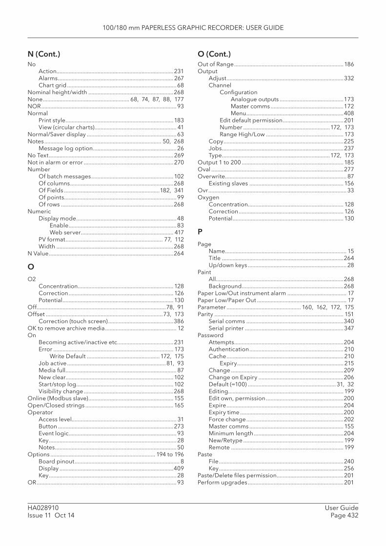
100/180 mm PAPERLESS GRAPHIC RECORDER: USER GUIDE
User GuidePage 432
HA028910Issue 11 Oct 14
O (Cont.)No
Action.............................................................................231Alarms ............................................................................ 267Chart grid ........................................................................68
Nominal height/width ........................................................268None ......................................................... 68, 74, 87, 88, 177NOR ......................................................................................... 93Normal
Print style .......................................................................183View (circular charts) ...................................................... 41
Normal/Saver display ...........................................................63Notes ............................................................................. 50, 268
Message log option ....................................................... 26No Text ..................................................................................269Not in alarm or error ...........................................................270Number
Of batch messages ......................................................102Of columns ....................................................................268Of Fields ...............................................................182, 341Of points ..........................................................................99Of rows ..........................................................................268
NumericDisplay mode ..................................................................48
Enable .......................................................................83Web server ............................................................. 417
PV format ................................................................ 77, 112Width .............................................................................268
N Value ..................................................................................264
OO2
Concentration............................................................... 128Correction ..................................................................... 126Potential .........................................................................130
Off .....................................................................................78, 91Offset .............................................................................73, 173
Correction (touch screen) ...........................................386OK to remove archive media ............................................... 12On
Becoming active/inactive etc. ....................................231Error ............................................................................... 173
Write Default ................................................172, 175Job active .................................................................81, 93Media full ......................................................................... 87New clear.......................................................................102Start/stop log ................................................................102Visibility change ...........................................................268
Online (Modbus slave) ........................................................ 155Open/Closed strings ..........................................................165Operator
Access level ..................................................................... 31Button ............................................................................273Event logic ....................................................................... 93Key .................................................................................... 28Notes ................................................................................ 50
Options ..................................................................... 194 to 196Board pinout ..................................................................... 8Display ...........................................................................409Key .................................................................................... 28
OR ............................................................................................ 93
Out of Range ........................................................................186Output
Adjust .............................................................................332Channel
Confi gurationAnalogue outputs ..........................................173Master comms ................................................172Menu ................................................................408
Edit default permission ........................................201Number .........................................................172, 173Range High/Low ................................................... 173
Copy ...............................................................................225Jobs ................................................................................237Type .......................................................................172, 173
Output 1 to 200 ...................................................................185Oval .......................................................................................277Overwrite ................................................................................ 87
Existing slaves ..............................................................156Ovr ........................................................................................... 33Oxygen
Concentration............................................................... 128Correction ..................................................................... 126Potential .........................................................................130
PPage
Name ................................................................................ 15Title ................................................................................264Up/down keys ................................................................. 28
PaintAll ....................................................................................268Background ...................................................................268
Paper Low/Out instrument alarm ....................................... 17Paper Low/Paper Out ........................................................... 17Parameter ................................................. 160, 162, 172, 175Parity ..................................................................................... 151
Serial comms ................................................................340Serial printer .................................................................347
PasswordAttempts ........................................................................204Authentication .............................................................. 210Cache ............................................................................. 210
Expiry ...................................................................... 215Change ..........................................................................209Change on Expiry ........................................................206Default (=100) .......................................................... 31, 32Editing............................................................................199Edit own, permission ...................................................200Expire .............................................................................204Expiry time ....................................................................200Force change ................................................................202Master comms .............................................................. 155Minimum length ...........................................................204New/Retype ..................................................................199Remote ..........................................................................199
PasteFile ..................................................................................240Key ..................................................................................256
Paste/Delete fi les permission ............................................201Perform upgrades ...............................................................201
N (Cont.)
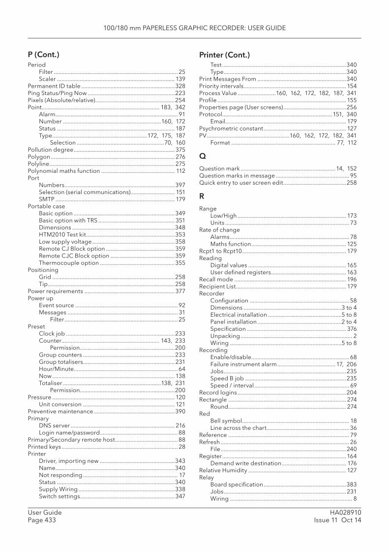
100/180 mm PAPERLESS GRAPHIC RECORDER: USER GUIDE
HA028910Issue 11 Oct 14
User GuidePage 433
P (Cont.) Printer (Cont.)Period
Filter ................................................................................. 25Scaler ............................................................................. 139
Permanent ID table .............................................................328Ping Status/Ping Now .........................................................223Pixels (Absolute/relative) ....................................................254Point............................................................................. 183, 342
Alarm ................................................................................ 91Number ................................................................160, 172Status ............................................................................. 187Type ..............................................................172, 175, 187
Selection .........................................................70, 160Pollution degree .................................................................. 375Polygon ................................................................................. 276Polyline ..................................................................................275Polynomial maths function ................................................ 112Port
Numbers ........................................................................397Selection (serial communications)............................. 151SMTP .............................................................................. 179
Portable caseBasic option ..................................................................349Basic option with TRS .................................................. 351Dimensions ...................................................................348HTM2010 Test kit ..........................................................353Low supply voltage ......................................................358Remote CJ Block option .............................................359Remote CJC Block option ..........................................359Thermocouple option .................................................355
PositioningGrid ................................................................................258Tip ...................................................................................258
Power requirements ...........................................................377Power up
Event source ................................................................... 92Messages ........................................................................ 31
Filter .......................................................................... 25Preset
Clock job .......................................................................233Counter ................................................................ 143, 233
Permission ..............................................................200Group counters ............................................................233Group totalisers ............................................................231Hour/Minute....................................................................64Now ................................................................................ 138Totaliser ................................................................138, 231
Permission ..............................................................200Pressure ................................................................................ 120
Unit conversion ............................................................ 121Preventive maintenance .....................................................390Primary
DNS server .................................................................... 216Login name/password...................................................88
Primary/Secondary remote host .........................................88Printed keys ............................................................................ 28Printer
Driver, importing new .................................................343Name ..............................................................................340Not responding .............................................................. 17Status .............................................................................340Supply Wiring ...............................................................338Switch settings..............................................................347
Test .................................................................................340Type ................................................................................340
Print Messages From ..........................................................340Priority intervals ...................................................................154Process Value .........................160, 162, 172, 182, 187, 341Profi le .................................................................................... 155Properties page (User screens) .........................................256Protocol........................................................................151, 340
Email............................................................................... 179Psychrometric constant ...................................................... 127PV ......................................................160, 162, 172, 182, 341
Format .................................................................... 77, 112
QQuestion mark ..............................................................14, 152Question marks in message ................................................ 95Quick entry to user screen edit .........................................258
RRange
Low/High ....................................................................... 173Units ................................................................................. 73
Rate of changeAlarms .............................................................................. 78Maths function .............................................................. 125
Rcpt1 to Rcpt10 .................................................................... 179Reading
Digital values ................................................................165User defi ned registers .................................................163
Recall mode ......................................................................... 196Recipient List ........................................................................ 179Recorder
Confi guration ................................................................. 58Dimensions ................................................................3 to 4Electrical installation ................................................5 to 8Panel installation .......................................................2 to 4Specifi cation ................................................................. 376Unpacking ......................................................................... 2Wiring .........................................................................5 to 8
RecordingEnable/disable ................................................................68Failure instrument alarm ...................................... 17, 206Jobs ................................................................................235Speed B job ..................................................................235Speed / interval .............................................................. 69
Record logins .......................................................................204Rectangle ............................................................................. 274
Round ............................................................................. 274Red
Bell symbol ...................................................................... 18Line across the chart ...................................................... 36
Reference ............................................................................... 79Refresh .................................................................................... 26
File ..................................................................................240Register .................................................................................164
Demand write destination .......................................... 176Relative Humidity ................................................................ 127Relay
Board specifi cation ......................................................383Jobs ................................................................................231Wiring ................................................................................ 8
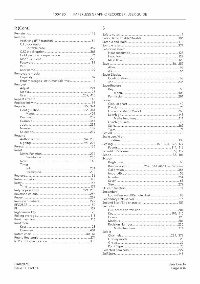
100/180 mm PAPERLESS GRAPHIC RECORDER: USER GUIDE
User GuidePage 434
HA028910Issue 11 Oct 14
Remaining .............................................................................148Remote
Archiving (FTP transfer).................................................54CJ block option
Portable case .........................................................359CJC block option ......................................................... 361Cold junction compensation........................................ 76Modbus Client ..............................................................223Password .......................................................................199Path ..................................................................................88User name .....................................................................199
Removable mediaCapacity .......................................................................... 87Error messages (instrument alarms) ........................... 17
RemoveAdjust .............................................................................221Media ............................................................................... 28User .......................................................................209, 410
Repeat after/in .....................................................................148Replace {n} with...................................................................... 95Reports ..........................................................................25, 341
Confi guration ......................................................182, 341Menu .......................................................................409
Destination ....................................................................239Example .........................................................................344Jobs ................................................................................239Number .........................................................................182Selection........................................................................239
RequireAuthorization .........................................................94, 205Signing ................................................................... 94, 204
Re-scan .................................................................................156Reset
Maths Function .............................................................232Permission ..............................................................200
Now ................................................................................148Timer
Job ..........................................................................234Permission ..............................................................200
Restore .................................................................................... 56Retransmission .................................................................... 173Retry ...................................................................................... 155
Time ............................................................................... 179Retype password ........................................................199, 208Reversed colour ...................................................................268Revert ....................................................................................257Revision numbers ................................................................229RFC2822 ...............................................................................180RH .......................................................................................... 127Right arrow key ...................................................................... 28Rolling average .................................................................... 118Root mass fl ow ..................................................................... 116Root menu
Keys .................................................................................. 28Overview .......................................................................401
Rotate chart .....................................................................40, 67Round Rectangle ................................................................. 274RTD input specifi cation ......................................................380
SSafety notes .............................................................................. 1Sales Demo Enable/Disable ..............................................386Sample and Hold ................................................................. 110Sample rates ........................................................................377Saturated steam
Heat consumed ............................................................ 123Heat fl ow ........................................................................122Mass fl ow ....................................................................... 120
Save ............................................................................... 56, 257After .................................................................................63As ...................................................................................... 56
Saver DisplayConfi guration .................................................................63Job .................................................................................236
Save/RestoreKey .................................................................................... 55
Menu .......................................................................403Permission .....................................................................201
ScaleCircular chart .................................................................. 42Divisions .......................................................................... 74Divisions (Major/Minor) ...............................................268Low/high ........................................................................143
Maths functions ......................................................111Low/high/units................................................................ 73Style................................................................................269Type .................................................................................. 74
Scaled ..................................................................................... 73Scale Low/High
Totaliser ......................................................................... 139Scaling....................................................... 160, 164, 172, 177
Factor .................................................................... 114, 116Scientifi c PV format ...................................................... 77, 112Scope .............................................................................82, 101Screen
Brightness .......................................................................63Builder option ....................252. See also User ScreensCalibration ....................................................................386Import/Export ................................................................ 56Number .........................................................................264Saver ................................................................................63Size .................................................................................279
SD card location .................................................................... 11Secondary
Login/Password/Remote Host .....................................88Secondary DNS server ....................................................... 216Second Start/End character .............................................. 151Security
Full, access permission ...............................................201Key ......................................................................... 197, 410Levels ............................................................................. 198Modbus .........................................................................281Revision Number ..........................................................230
Maths function .......................................................111Select
Channels ...............................................................221, 372Display mode .................................................................. 28Group ............................................................................... 29Point Type ........................................................................ 70
Selected item colour ..........................................................227Self Start................................................................................148
R (Cont.)
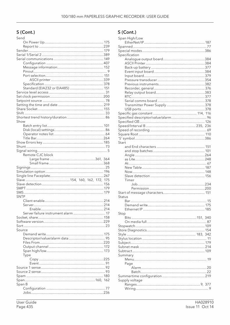
100/180 mm PAPERLESS GRAPHIC RECORDER: USER GUIDE
HA028910Issue 11 Oct 14
User GuidePage 435
S (Cont.) S (Cont.)Send
On Power Up ................................................................. 175Report to .......................................................................239
Sender ................................................................................... 179Serial 1/Serial 2 ....................................................................389Serial communications ....................................................... 149
Confi guration ...............................................................407Message information................................................... 152Pinout ................................................................................. 9Port selection ................................................................ 151
ASCII printer ..........................................................339Specifi cation .................................................................378Standard (EIA232 or EIA485) ..................................... 151
Service level access .............................................................. 31Set clock permission ...........................................................200Setpoint source ..................................................................... 78Setting the time and date .................................................. 219Share Socket ........................................................................ 155Shift ......................................................................................... 33Shortest trend history/duration ..........................................86Show
Batch entry list .............................................................. 101Disk (local) settings ........................................................86Operator notes list .........................................................64Title Bar ..........................................................................264
Show Errors key ...................................................................185Shunt ....................................................................................... 73Signal wiring ............................................................................. 5
Remote CJC blockLarge frame ..................................................361, 364Small frame ............................................................368
Signings .................................................................................. 25Simulation option ................................................................ 196Single line Faceplate ........................................................... 267Slave .................................................154, 160, 162, 172, 175Slave detection ....................................................................156SMPT ..................................................................................... 179SMS ........................................................................................ 179SNTP
Client enable................................................................. 214Server ............................................................................. 214
Enable ..................................................................... 214Server failure instrument alarm ................................... 17
Socket, share ........................................................................ 158Software version ..................................................................229Sort .......................................................................................... 23Source
Demand write ............................................................... 175Descriptor/value/alarm data ........................................ 95Files From ......................................................................220Output channel ............................................................ 172Span high/low............................................................... 173Type
Copy .......................................................................225Event ......................................................................... 91
Source 1 sense ....................................................................... 92Source 2 sense ....................................................................... 93Spam .....................................................................................180Span..............................................................................160, 162Span B
Confi guration ................................................................. 77Jobs ................................................................................236
Span High/LowEtherNet/IP ................................................................... 187
Spanned ................................................................................. 77Special modes .....................................................................386Specifi cation
Analogue output board ..............................................384ASCII Printer .................................................................384Back-up battery ...........................................................377Event input board ........................................................384Input board ...................................................................379Pressure transducer ....................................................354Previous instruments...................................................382Recorder, general ........................................................ 376Relay output board ......................................................383RTC .................................................................................377Serial comms board ....................................................378Transmitter Power Supply ..........................................378USB ports ......................................................................378
Specifi c gas constant ................................................ 114, 116Specifi ed descriptor/value/alarm ....................................... 96Specifi ed O� ........................................................................ 126Speed/Interval B ....................................................... 235, 236Speed of recording .............................................................. 69Square Root ......................................................................... 110'S' symbol .............................................................................386Start
and End characters ..................................................... 151and stop batches ......................................................... 101Angle .............................................................................264as Lite .............................................................................248At ...................................................................................... 67New Table ..................................................................... 187Now ................................................................................148Slave detection ............................................................156Timer
Job ..........................................................................234Permission .............................................................200
Start of message characters.............................................. 151Status
Bar .................................................................................... 15Demand write ............................................................... 175Ethernet IP ....................................................................185
StopBits ........................................................................151, 340On media full .................................................................. 87
Stopwatch ............................................................................109Store Diagnostics ................................................................154Style ............................................................................ 183, 342Stylus location ....................................................................... 11Subject .................................................................................. 179Subnet mask ........................................................................ 214Subtract ................................................................................109Summary
Menu ................................................................................ 19Page
Alarm ........................................................................ 20Batch......................................................................... 22
Summertime confi guration ............................................... 219Supply voltage
Ranges ...................................................................... 9, 377Wiring ................................................................................ 9
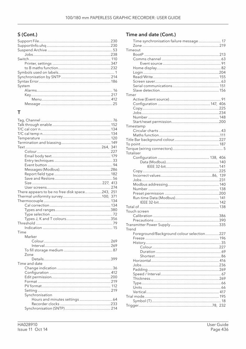
100/180 mm PAPERLESS GRAPHIC RECORDER: USER GUIDE
User GuidePage 436
HA028910Issue 11 Oct 14
Support File..........................................................................230SupportInfo.uhq ..................................................................230Suspend Archive ................................................................... 53
Jobs ................................................................................238Switch .................................................................................... 110
Printer, settings ............................................................347to B maths function ......................................................232
Symbols used on labels .......................................................... 1Synchronisation by SNTP ................................................... 214Syntax Error ..........................................................................186System
Alarms .............................................................................. 16Key .................................................................................. 217
Menu ....................................................................... 412Message .......................................................................... 25
TTag, Channel .......................................................................... 76Talk through enable ............................................................ 152T/C cal corr n ........................................................................ 134T/C cal temp n ...................................................................... 134Temperature ........................................................................ 120Termination and biassing ................................................... 149Text .............................................................................. 264, 341
Colour ............................................................................227Email body text ............................................................. 179Entry techniques ............................................................ 33Event button ................................................................... 94Messages (Modbus).....................................................286Report fi eld type ..........................................................182Save and Restore............................................................ 56Size ........................................................................ 227, 413User screens.................................................................. 274
There appears to be no free disk space... ..............243, 251Thermal uniformity survey ........................................100, 371Thermocouple ..................................................................... 134
Cal correction ............................................................... 134Types and ranges .........................................................380Type selection ................................................................ 72Types J, K and T colours ..............................................356
Threshold ............................................................................... 79Indication ........................................................................ 15
TimeMarker
Colour .....................................................................269Interval ....................................................................269
To fi ll storage medium .................................................. 87Zone
Details .....................................................................399Time and date
Change indication ......................................................... 36Confi guration ............................................................... 412Edit permission.............................................................200Format ........................................................................... 219PV format ....................................................................... 112Setting ........................................................................... 219Synchronisation
Hours and minutes settings ..................................64Recorder clocks ....................................................233
Synchronisation (SNTP) ............................................... 214
Time synchronisation failure message ....................... 17Zone ............................................................................... 219
TimeoutBootP ............................................................................. 213Comms channel .............................................................63
Event source ............................................................ 91Home display .................................................................. 82Login ..............................................................................204Read/Write .................................................................... 155Screen saver ....................................................................63Serial communications ................................................ 151Slave detection .............................................................156
TimerActive (Event source) ..................................................... 91Confi guration ......................................................147, 406Copy ...............................................................................225Jobs ................................................................................234Number .........................................................................148Start/reset permission .................................................200
TimestampCircular charts ................................................................43Maths function ...............................................................111
Title Bar background colour ..............................................227To point ................................................................................. 187Torque (wiring connectors) .................................................... 5Totaliser
Confi guration ..................................................... 138, 406Data (Modbus) .......................................................140
IEEE 32-bit .......................................................141Copy ...............................................................................225Incorrect values .....................................................86, 139Jobs ................................................................................231Modbus addressing.....................................................140Number ......................................................................... 138Preset permission ........................................................200Run-time Data (Modbus) ............................................. 141
IEEE 32-bit .............................................................. 142Total of .................................................................................. 138Touch screen
Calibration ....................................................................386Precautions ...................................................................390
Transmitter Power Supply ..................................................335Trend
Foreground/Background colour selection ..............227Freeze ............................................................................ 196History.............................................................................. 35
Colour .....................................................................227Duration ................................................................... 69Shortest ....................................................................86
Horizontal ...................................................................... 416Jobs ................................................................................236Padding .........................................................................269Speed / Interval .............................................................. 67Thickness .......................................................................269Type ..................................................................................66Units .................................................................................66Vertical ........................................................................... 417
Trial mode ............................................................................. 195Symbol (T) ....................................................................... 18
Trigger ............................................................................78, 232
Time and date (Cont.)S (Cont.)
100/180 mm PAPERLESS GRAPHIC RECORDER: USER GUIDE
HA028910Issue 11 Oct 14
User GuidePage 437
Truncation of values .............................................................. 14'T' symbol ......................................................................18, 195TUS ...............................................................................100, 371Type ..................................................................................78, 94
UUCMM ......................................................................... 184, 224Unable to connect to host ................................................. 251Unable to resolve hostname.............................................. 251Unack’d
Alarm on Group ............................................................. 92Point alarm ...................................................................... 91
Unconnected Message Manager ........................... 184, 224Unconnected messaging ...................................................184Unicode .........................................................................89, 152Units ......................................................................................254
Counter ..........................................................................143Font ................................................................................269Input range ..................................................................... 73Pressure conversion .................................................... 121Scale ................................................................................. 73Scaler ............................................................................. 139Totaliser ......................................................................... 138
Universal input board wiring ................................................. 7Unlatched ............................................................................... 78Unlock fl ap
Key .................................................................................... 28Permission .....................................................................201
Unpacking the recorder ......................................................... 2Update when ........................................................................269Upgrade ................................................................................220
Confi guration menu .................................................... 412Initiation .........................................................................220Permission .....................................................................201
USBInstrument alarms .......................................................... 17Lock-up ..........................................................................378Port location ................................................................... 11Specifi cation .................................................................378
UseCounter as batch number ...........................................102Last properties .............................................................258Temperature or pressure ............................................ 120Text for batch fi eld 1 ....................................................102
UserAdd and Remove .........................................................208Defi ned
Descriptor .............................................................. 132Registers ................................................................163
Linearisation table ......................................................... 98Confi guration menu .............................................405Import/Export ......................................................... 57Number .................................................................... 98Units ...................................................................73, 98
Logged In event source ................................................ 92Login account disabled................................................. 92Name
Full ...........................................................................208Remote ...................................................................199
Screens ............................................................................84Basic/Advanced selection ...................................258Component info on screens................................258Component list .....................................................255Creation ..................................................................254Image Error ............................................................273Importing/Exporting ............................................253Key descriptions ......................................... 256, 257Number of ................................................................84Option ....................................................................252Parameters
Advanced ........................................................265Basic .................................................................263
Properties page ....................................................256Quick entry ............................................................258
Username ............................................................................. 155Use Summertime ................................................................. 219
VValue
and UnitsFaceplate style ...................................................... 267
Changes ........................................................................269Channel ........................................................................... 72Counter ..........................................................................143Font ................................................................................269Register..........................................................................164Totaliser ......................................................................... 138
VerticalAlignment ......................................................................269Bargraph .................................................................44, 269
Display mode enable .............................................83Grid total .......................................................................270Minor Divisions .............................................................270Trend .......................................................................36, 271
Display mode enable .............................................83Trend display mode
Web Server ............................................................ 417Views
Confi guration ................................................................. 82Menu .......................................................................404
Virtual channels confi guration ................................ 195, 409Virus susceptibility ..............................................................378Visible
Alarm ..............................................................................270Channel .........................................................................270Operator ........................................................................270Value ..............................................................................270
WWeb server ........................................................................... 415
Enable ............................................................................202Weekly ............................................................................. 87, 88Wet bulb temperature ........................................................ 127When visible .........................................................................270While [alarm] active, inactive, unacknowledged 81, 93, 231Width .....................................................................................264Wire size
Signal ................................................................................. 5Supply ................................................................................ 9
User (Cont.)T (Cont.)
100/180 mm PAPERLESS GRAPHIC RECORDER: USER GUIDE
User GuidePage 438
HA028910Issue 11 Oct 14
WiringAnalogue outputs ............................................................ 8ASCII printer .................................................................338D-type connector ............................................................. 9Event inputs ...................................................................... 8Input board ....................................................................... 7Modbus .........................................................................280Option boards .................................................................. 8Relay ................................................................................... 8Remote CJC block
Large frame ..................................................361, 364Small frame ............................................................368
Serial comms ........................................................... 9, 149Signal ................................................................................. 5Supply (Mains) .................................................................. 9Transmitter Power Supply ...........................................337Wire size
Signal .......................................................................... 5Supply ......................................................................... 9
with unapplied changes .....................................................204Wizard (Ethernet IP)
Ethernet IP .....................................................................185Worst case error calculation ..............................................381Write
Enable ............................................................................ 175Number ......................................................................... 175to a specifi c register .................................................... 176
W (Cont.) XX1 ............................................................................................. 98Xon/Xoff ...............................................................................347XOR ......................................................................................... 93X points/position .................................................................264
YY1 ............................................................................................. 98You are already running ... message .......................243, 251You are authenticating Full Bridge... message ............... 251Y points/position .................................................................264
ZZ-Factor ................................................................................. 115Zirconia probe ..................................................................... 128Zone
B, select job ..................................................................236Chart area ........................................................................ 77Time
Details .....................................................................399Selection ................................................................ 219
Z value ................................................................................... 113

100/180 mm PAPERLESS GRAPHIC RECORDER: USER GUIDE
HA028910Issue 11 Oct 14
User GuidePage 439
This page is deliberately left blank


Eurotherm: International sales and service www.eurotherm.com
© Copyright Eurotherm Limited 2014
Invensys, Eurotherm, the Eurotherm logo, Chessell, EurothermSuite, Mini8, Eycon, Eyris, EPower, EPack nanodac, piccolo, versadac, optivis, Foxboro, and Won-derware are trademarks of Invensys plc, its subsidiaries and affi liates. All other brands may be trademarks of their respective owners.All rights are strictly reserved. No part of this document may be reproduced, modifi ed or transmitted in any form by any means, neither may it be stored in a retrieval system other than for the purpose to act as an aid in operating the equipment to which the document relates, without the prior written permission of Invensys Eurotherm Limited.Eurotherm Limited pursues a policy of continuous development and product improvement. The specifi cations in this document may therefore be changed without notice. The information in this document is given in good faith, but is intended for guidance only. Eurotherm Limited will accept no responsibility for any losses arising from errors in this document.
HA028910/11 (CN32295)
Contact Information
Eurotherm Head Offi ce Worldwide OffricesFaraday Close, www.eurotherm.com/globalDurrington,Worthing, West SussexBN13 3PL
Sales Enquiries General EnquiriesT +44 (01903) 695888 T +44 (01903) 268500F 0845 130 9936 F 9845 265982
Scan for local contacts
Represented by: