Embed Size (px)
Citation preview

32
AOYUE TONGYI ELECTRONIC EQUIPMENT FACTORY Jishui Industrial Zone, Nantou, Zhongshan City, Guangdong Province, P. R. China www.aoyue.com
Copyright © 2007
INSTRUCTION MANUAL
6031 6031 SiroccoSeries
Lead-Free Repairing
Thank you for purchasing Aoyue 6031 SiroccoSeries LeadFree Repairing System.
It is important to read the manual before using the equipment. Please keep manual in accessible place for future reference.

2
This manual is designed to familiarize and instruct the technician with the proper operation and maintenance of the equipment. The “Care and Safety Precautions” section explains the hazards of using any type of soldering or reworking device. Please read carefully and observe the guidelines in order to maximize usage and minimize the risk of injury or accidents .
31
AIR NOZZLES*
(*) Sold Separately
NOTE: For Sirocco series hotair gun, do not use single straight air nozzles lower than 6 mm in diameter.

30
(*) Sold Separately
REPLACEMENT TIPS*
3
TABLE OF CONTENTS
Product Description …………………………………… 4
Package Inclusion ………………………………………... 5
Spare Parts List …………………………………… 5
Specifications ………………………………………... 6
Functions and Features …………………………………... 7
Safety Precautions ………………………………………... 8
Assembly and Preparation ……………………………… 9
Control Panel Guide …………………………………… 10
Operating Guidelines …………………………………… 11 — 25
Initial Procedures
Hot Air Gun
SMD Reworking Initial Procedures
SMD Extraction Guide
SMD Soldering Guide (Convection-Style Reworking)
Traditional Reworking Guide
Soldering Iron
Auto-Sleep Mode (Hot Air Gun)
Changing Auto-Sleep Mode Time (Hot Air Gun)
Activating Soldering Iron Auto-Sleep Mode
Utilizing the Solder Iron Digital Temperature Calibration
Care and Maintenance ………………………………. 26 — 27
Basic Troubleshooting Guide …………………………. 28 — 29
Miscellaneous Section ………………………………. 30 — 31
Replacement Tips
Air Nozzles
4
PRODUCT DESCRIPTION
The Aoyue 6031 SiroccoSeries SMD Rework Station is a 2in1 equip ment that combines the functionality of Hot Air Gun and Soldering Iron in one sophisticated package.
One of the notable features of this device is the autosleep mode of both the Hot Air Gun and Soldering Iron — both independent of each other. This functionality protects the device (and all its components) from excessive heat for added safety and system protection. The uniquely designed Hot Air Gun with integrated Siroccotype fan provides efficient airflow and regulation for reworking components made of plastic materials. In addition, the well crafted air gun provides easy, snugfit grip for manageable control of hot air direction. These and all the complete features will be discussed in greater detail in the succeeding sections of this manual.
Finally, the unique, innovative design with digital control and display panel provides precision, safety, and ease of use to match all reworking requirements.
29
BASIC TROUBLESHOOTING GUIDE
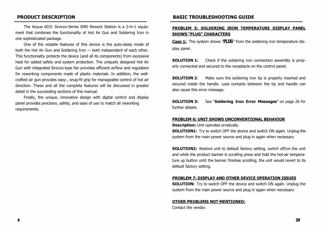
PROBLEM 5: SOLDERING IRON TEMPERATURE DISPLAY PANEL SHOWS “PLUG” CHARACTERS
Case 1: The system shows “PLUG” from the soldering iron temperature dis
play panel .
SOLUTION 1: Check if the soldering iron connection assembly is prop erly connected and secured to the receptacle on the control panel.
SOLUTION 2: Make sure the soldering iron tip is properly inserted and secured inside the handle. Lose contacts between the tip and handle can also cause this error message.
SOLUTION 3: See “Soldering Iron Error Messages” on page 26 for further details.
PROBLEM 6: UNIT SHOWS UNCONVENTIONAL BEHAVIOR Description: Unit operates erratically. SOLUTION1: Try to switch OFF the device and switch ON again. Unplug the system from the main power source and plug in again when necessary
SOLUTION2: Restore unit to default factory setting. switch off/on the unit and while the product banner is scrolling press and hold the hotair tempera ture up button until the banner finishes scrolling, the unit would revert to its default factory setting.
PROBLEM 7: DISPLAY AND OTHER DEVICE OPERATION ISSUES SOLUTION: Try to switch OFF the device and switch ON again. Unplug the system from the main power source and plug in again when necessary
OTHER PROBLEMS NOT MENTIONED: Contact the vendor.

28
PROBLEM 1: THE UNIT HAS NO POWER 1. Check if the unit is switched ON. 2. Check the fuse. Replace with the same type if fuse is blown. 3. Check the power cord and make sure there are no disconnections. 4. Verify that the unit is properly connected to the power source.
PROBLEM 2: HOTAIR GUN TEMPERATURE DISPLAY IS ALWAYS ABOVE 500 o C Description: Constant display of above 500 o C temperature from the panel then displays an “Err1” on the panel after a few minutes. SOLUTION: The thermal sensor may be broken and needs to be replaced.
PROBLEM 3: HOTAIR GUN ACTUAL AIR TEMPERATURE IS NOT IN CREASING Description: Actual temperature reading is not increasing or decreasing based on desired level. SOLUTION: The heating element may be broken or is at the end of its life and needs to be replaced.
PROBLEM 4: NO AIR IS COMING OUT OF THE HOT AIR GUN Description: No air is flowing out of the nozzle, the nozzle heats up, and no sound can be heard on the air intake end of the hand piece. SOLUTION: The fan may be broken and needs to be replaced. See replacing the Fan on page 27.
BASIC TROUBLESHOOTING GUIDE
5
PACKAGE INCLUSION
Hot Air Gun
Air Nozzles (1010, 1194, 1195)
Power Cord 939 Vacuum Suction Pen G001 IC Popper
2630B Soldering Iron Holder with Solder Wire Stand
Hot Air Gun Holder
PART NO. DESCRIPTION
10094 Hot air gun heating element
30106S Plastic handle of hot air gun
S009 Hot air gun complete handle
20962 Hot air gun metal pipe
P002 Diaphragm pump
30127S Soldering Iron plastic handle
B011 Soldering Iron complete handle
SPARE PARTS GUIDE
6031 Main Station
LF2B Tip
30150J Heat Resistant Pad

6
MAIN STATION Power Input Available in 110V / 220V
Station Dimensions 204 (w) x 143 (h) x 212 (d) mm
Weight 2.5 Kgs.
HOT AIR GUN
Power Consumption 600W
Temperature Range 100°C 480°C
Heating Element Type Metal Heating Core
Fan Type Sirocco
Air Capacity 35 l/min (max)
SOLDERING IRON
Power Consumption 60W
Temperature Range 200°C 480°C
Heating Element Type PTC Element
Output Voltage 24V
SPECIFICATIONS
27
CARE & MAINTENANCE
Replacing the heating element of the Hot Air Gun 1. Detach screws shown in the illustration, and slide off the nozzle. 2. Pop out the heating element, detach the heating element by pulling away
both side of the white plastic connector. 3. Unsolder the last two wires (Thermal sensor) connecting the hand piece
and heating element together. 4. Attach the new heating element’s sensor wires to the hand piece. this
can be done by soldering the wires together. Take note of the color code of the wires. Use a heat shrinking tube or electrical tape to protect the solder joints from shorts .
5. Reattach the white plastic connector. 6. Replace the nozzle and refasten screws in the hand piece.
screws screws
Replacing the Fan 1. When the fan has been deemed inoperable or damaged it may be re
placed by the following steps. 2. Follow steps 1 and 2 of replacing the heating element. 3. Pull out the fan and unsolder the ends of its power wires. Take note of
the placement of the wires as the fan supply has a positive and negative terminal.
4. Resolder the two wires to the new fan. 5. Replace the nozzle and refasten the screws in the hand piece.

26
Soldering Iron Tip Always keep the solderplated section of the tip/nozzle coated with a small amount of solder. Oxide coating on the tip of the nozzle reduces its heat conductivity. Coating the tip with a small amount of fresh solder ensures maximum heat conductivity is obtained. Replacing the Soldering Iron Tip 1. Always unplug the device from the main power source when removing or
replacing the soldering tip. 2. If the tip is hot, use the heat resistant pad to pull it out. 3. Insert the new tip fully into the handle. If the tip is not fully inserted (or
if the tip is damaged), the device will show the following from the SOL DERING IRON TEMPERATURE display panel (“8”).
Checking the soldering iron connection cord for damages 1. Remove the soldering iron tip and nipple. 2. Push the socket out from the handle assembly. 3. Measure the resistance values between the connector and the lead wires
at the socket are as follows:
CARE & MAINTENANCE
Pin 1 Red ( + ) Pin 3 Blue (ground) Pin 5 Black ( ) If any value exceeds 0Ω (shorted) or ∞ (infinitely large — open), replace the handle assembly.
Soldering Iron Error Messages 1. Soldering Iron connection assembly is not
connected or not properly connected to the receptacle on the control panel.
2. Soldering iron tip is damaged and needs to be replaced.
3. Thermal sensor is either disconnected or damaged and needs to be fixed or replaced.
7
● Microprocessorcontrolled ESD safe equipment. ● Leadfree compatible, 2in1 multifunctional repairing system. Combines
the functions of hot air gun and soldering iron in one package. ● Uniquely designed, easygrip hand piece with integrated lownoise fan.
Provides snugfit clasp for easy control of hot air direction.
● Digital offset for easy digital temperature calibration from –70 to +70 degrees. ● Siroccotype fan providing seamless airflow and circuit protection. ● Equipped with hand piece holder for saving bench space and safety. ● All digital display of hot air temperature, soldering iron temperature, and
air pressure with touch type panel controls for precision and ease of use. ● Uniquely designed compound tip that integrates the ceramic heating ele
ment and sensor in just one component. Replacing tips is as easy as slip ping it in/out of the compatible 24V soldering iron.
● Userprogrammable 1 to 30minute idletoautosleep mode of hot air gun (with 5 minutes as default) — switches OFF fan and heating element when device is not in use for a long period.
● Builtin autocooling process that protects the system and its components from excessive heat, prolonging usage life.
● Builtin, userprogrammable autosleep mode for soldering iron. ● Hot air gun convectionstyle heating allows low hot air pressure to pass on target
device/s and concentrate on the solder joints. Usable as heat reflow device.
● Compatibility with different kind of soldering tips. See page 22. ● Compatibility with air nozzles of various types. See page 23. ● Suitable for various SMD and BGA reworking tasks. ● Excellent for reworking components made of plastic materials.
FUNCTIONS & FEATURES
8
SAFETY PRECAUTIONS
● Check each component after opening the package to make sure every thing is in good condition. If there are any suspected damage, do not use the item and report the issue to your vendor.
● Turn OFF the main power switch and unplug the device from the main power source when moving the device from one location to another.
● Do not strike or subject the main unit (and all its components) to physi cal shock. Use carefully to avoid injury and damage to any part.
● Handle with care. Never drop or sharply jolt the unit. Contains delicate parts that may break if the unit is dropped.
● Make sure the equipment is always grounded. Always connect power to a grounded receptacle.
● Temperature may reach as high as 480°C when switched ON. Do not use the device near flammable gases, paper and other flamma ble materials. Do not touch heated parts, which can cause severe burns. Do not touch metallic parts near the tip.
● Disconnect the plug from the main power source if the unit will not be used for a long period. Power OFF the device during breaks, if possible.
● Use only genuine replacement parts. Turn off power and let the unit cool down before replacing any part.
● The unit may produce a small amount of smoke and unusual odor dur ing initial usage. This is normal and should not yield any negative result when reworking.
● Soldering process produces smoke — use on well ventilated places. ● Do not alter the unit, specifically the internal circuitry, in any manner.
CAUTION: Improper usage can cause serious injury to personnel and/or damage to equipment and work area. For your own safety, please observe the following precautions.
25
OPERATING GUIDELINES
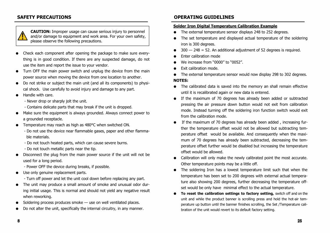
Solder Iron Digital Temperature Calibration Example ● The external temperature sensor displays 248 to 252 degrees. ● The set temperature and displayed actual temperature of the soldering
iron is 300 degrees. ● 300 — 248 = 52. An additional adjustment of 52 degrees is required. ● Enter calibration mode ● We increase from “0000” to “0052”. ● Exit calibration mode. ● The external temperature sensor would now display 298 to 302 degrees. NOTES: ● The calibrated data is saved into the memory an shall remain effective
until it is recalibrated again or new data is entered. ● If the maximum of 70 degrees has already been added or subtracted
pressing the air pressure down button would not exit from calibration mode. Instead turning off the soldering iron function switch would exit from the calibration mode.
● If the maximum of 70 degrees has already been added , increasing fur ther the temperature offset would not be allowed but subtracting tem perature offset would be available. And consequently when the maxi mum of 70 degrees has already been subtracted, decreasing the tem perature offset further would be disabled but increasing the temperature offset would be allowed.
● Calibration will only make the newly calibrated point the most accurate. Other temperature points may be a little off.
● The soldering Iron has a lowest temperature limit such that when the temperature has been set to 200 degrees with external actual tempera ture also showing 200 degrees, further decreasing the temperature off set would be only have minimal effect to the actual temperature.
● To reset the calibration settings to factory setting, switch off and on the unit and while the product banner is scrolling press and hold the hotair tem perature up button until the banner finishes scrolling, the Set /Temperature cali bration of the unit would revert to its default factory setting.

24
OPERATING GUIDELINES
K. Utilizing the Solder Iron Digital Temperature Calibration By default, the system is properly calibrated but for some cases when
an little adjustment of the soldering iron temperature is required the follow ing procedure can be done.
1. Turn on the soldering iron function switch. 2. Set to appropriate temperature you want to calibrate. Place the tip
of the soldering iron on an external temperature sensor. 3. The readings on the external temperature sensor should be more or
less equal to the displayed temperature. 4. If there are large discrepancy in the temperature reading we can re
calibrate temperature setting. 5. While the solder iron is operating make sure the hot air gun is in off
mode (“0FF” is displayed on the panels “6” and “7”), hold the air
pressure UP button for a few seconds until four zeroes are displayed “0000” .
4. Adjust the temperature compensation using the UP and DOWN but tons of the Soldering iron adjustment buttons.
5. A zero “0” on the first digit signifies addition to the current tempera ture and a minus “” on the first digit will subtract the displayed value from the current settings.
6. Confirm the change by pressing the air pressure down button. 7. The system will immediately switch back to operation and the tem
Initial display when in calibra tion mode
Increase tem perature by 38
degrees
Decrease tem perature by 30
degrees
Exit from cali bration mode
9
Figure 1. Soldering iron stand with solder wire holder
A. Soldering Iron 1. Install the solder wire to the soldering iron holder as in Figure 1.
2. Connect the soldering iron cord assembly to the 3pin output terminal found at the lower middle portion of the main unit. Refer to CONTROL PANEL GUIDE page for buttons and controls location.
3. Place the soldering iron to the soldering iron stand as shown above.
B. Hot Air Gun The Hot Air Gun holder is originally detached for packaging purpose. To attach the Hot Air Gun holder, 1. Align the screw holes of the hot air gun holder to the two holes on the left side of the station.
2. Attach the holder with two screws onto the main unit. 3. Place the hot air gun in the sensor controlled hot air gun holder to prepare for usage.
ASSEMBLY & PREPARATION
10
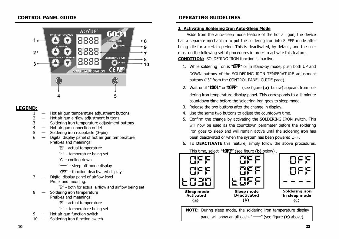
CONTROL PANEL GUIDE
LEGEND:1 — Hot air gun temperature adjustment buttons 2 — Hot air gun airflow adjustment buttons 3 — Soldering iron temperature adjustment buttons 4 — Hot air gun connection outlet 5 — Soldering iron receptacle (3pin) 6 — Digital display panel of hot air gun temperature
Prefixes and meanings: “H” actual temperature “h” temperature being set “C” cooling down “---” sleep off mode display “OFF” function deactivated display
7 — Digital display panel of airflow level Prefix and meaning:
“P” both for actual airflow and airflow being set 8 — Soldering iron temperature
Prefixes and meanings: “H” actual temperature “h” temperature being set
9 — Hot air gun function switch 10 — Soldering iron function switch
1
2
3
4 5
9
10
6
7 8
23
NOTE: During sleep mode, the soldering iron temperature display
panel will show an alldash, “----” (see figure (c) above).
OPERATING GUIDELINES
J. Activating Soldering Iron AutoSleep Mode Aside from the autosleep mode feature of the hot air gun, the device
has a separate mechanism to put the soldering iron into SLEEP mode after being idle for a certain period. This is deactivated, by default, and the user must do the following set of procedures in order to activate this feature. CONDITION: SOLDERING IRON function is inactive.
1. While soldering iron is “OFF” or in standby mode, push both UP and
DOWN buttons of the SOLDERING IRON TEMPERATURE adjustment buttons (“3” from the CONTROL PANEL GUIDE page).
2. Wait until “t001” or“t0FF” (see figure (a) below) appears from sol dering iron temperature display panel. This corresponds to a 1minute countdown time before the soldering iron goes to sleep mode.
3. Release the two buttons after the change in display. 4. Use the same two buttons to adjust the countdown time. 5. Confirm the change by activating the SOLDERING IRON switch. This
will now be used as the countdown parameter before the soldering iron goes to sleep and will remain active until the soldering iron has been deactivated or when the system has been powered OFF.
6. To DEACTIVATE this feature, simply follow the above procedures.
This time, select “tOFF” (see figure (b) below) .

22
OPERATING GUIDELINES
I. Changing SLEEP Mode Timer (HOT AIR GUN) By default, the system has 5minute countdown time before the hot air
gun goes to sleep mode. This can be altered by the following procedure.
1. While the hot sir gun is on standby mode (“0FF” is displayed on the
panels “6” and “7”), hold both UP and DOWN buttons of the HOT AIR GUN TEMPERATURE adjustment buttons.
2. Wait until “t005” is displayed on the Hot Air Gun Temperature dis play panel, “6”.
3. Release the buttons when “t005” appears. 4. Adjust the time using the same UP and DOWN buttons of the HOT
AIR GUN TEMPERATURE adjustment buttons. 5. Confirm the change by activating the HOT AIR GUN function switch. 6. The system will immediately switch back to operation and use the
defined countdown parameter for the entire usage. It will return to
NOTE: The sleep mode timer is configurable between 1 and 30 minutes.
Note: Sleep mode settings for HotAir gun and Soldering Iron is saved into the memory an shall remain effective until it is reset
or new data is entered.
11
IMPORTANT REMINDERS: 1. Make sure the equipment is placed on a flat stable surface and all heatgenerating components placed on their respective holders or stands.
2. Ensure all function switches are OFF prior to reworking. 3. Ensure all terminal connections are properly secured.
IMPORTANT: Please refer to the CONTROL PANEL GUIDE page for buttons and display panel directory.
OPERATING GUIDELINES
A. INITIAL PROCEDURES 1. Make sure all function switches are deactivated and all terminal connec
tions properly secured. Plug the device to the main power source using the power cord provided in the package.
2. Display panels 6 and 7 will temporarily show the product name in a
scrolling manner then display “OFF” in every row once the scroll is fin
ished (see below). The system will remain at this state until the user acti

12
OPERATING GUIDELINES
B. HOT AIR GUN 1. Follow initial procedures, “A. INITIAL PROCEDURES”. 2. Activate “HOT AIR GUN” function switch (“9” from the control panel). 3. The system will immediately start to blow air at an airflow rate of 50
while rapidly and safely increasing the air temperature to 100°C (default system operating parameters). These values will be reflected from the Hot Air Gun Air Temperature and Air Pressure display panels, “6” and “7” from the control panel, respectively.
4. Adjust the air flow level using the AIR PRESSURE adjustment buttons (“2” from the control panel).
5. Adjust the hot air gun air temperature using the HOT AIR GUN TEMPERA TURE adjustment buttons (“1” from the control panel). The prefix of the
display for Hot Air Gun Temperature will change from “H” to “h” indicating
that air temperature is being adjusted. It will return to “H” after a few
seconds of releasing the buttons and while the temperature is gradually increasing or decreasing until the desired temperature is reached. In the
Default System Parameters (Hot Air Gun)
H
21
6. When job is finished, deactivate the SOLDERING IRON activation switch. 7. Wait for the soldering iron to cool down before detaching the soldering
iron connection assembly from the 3pin receptacle at the control panel (if necessary).
8. Allow sufficient time for the soldering iron to completely cool down be fore keeping in a safe storage. (Optional but recommended)
NOTE: The soldering iron operating temperature is adjustable be tween 200°C and 480°C with an increment of 2° per step.
OPERATING GUIDELINES
H. AutoSleep Mode (Hot Air Gun) The device has a builtin autosleep mode feature such that if the Hot
Air Gun sits on its handle and remained idle after a certain period, the device will switch to sleep mode (provided the power delivered to the system re main uninterrupted). This mechanism is triggered by a countdown timer so when the time has elapsed, the system will blow air (at room temperature) at maximum rate in order to bring down the temperature. During this time, the prefix of the display for Hot Air Gun air temperature will also change
from “H” to “C”. Once the temperature drops to approximately 90°C, the Hot
Air Gun will automatically stop and show an alldash display indicating that
The device will automatically resume operation with the last userdefined parameters, i.e., hot air gun temperature and airflow level, when the Hot Air Gun is lifted again or removed from the handle.

20
OPERATING GUIDELINES
G. SOLDERING IRON 1. Connect the Soldering Iron connection assembly to the receptacle located
at the front of the control panel (item “5” from the CONTROL PANEL GUIDE page).
2. Follow the initial procedures (“A. INITIAL PROCEDURES”). 3. Activate the SOLDERING IRON activation switch (“10” from control panel).
This will automatically start to increase the temperature of the soldering iron to 350°C (default).
4. Adjust the soldering iron temperature using the SOLDERING IRON TEM PERATURE adjustment buttons (“3” from the control panel). The prefix of
the display for Hot Air Gun Temperature will change from “H” to “h” indi
cating that air temperature is being adjusted. It will return to “H” after a
few seconds of releasing the buttons and while the temperature is gradu ally increasing or decreasing until the desired temperature is reached. In the example below, the final (desired) hot air gun temperature is 280°C.
5. Start using the soldering iron as soon as the desired temperature is reached. Use the soldering iron temperature display panel for reference.
NOTE: The soldering iron has a memory function in which the last set tem perature would be the initial set temperature whenever the unit is turned off
13
OPERATING GUIDELINES
IMPORTANT: When adjusting the air temperature, it is strongly advised to increase the airflow level first in order to manage the system temperature. This is to protect the heating element inside the handle from excessive heat and avoid subjecting adjacent components of target device/s from thermal shock.
6. Reworking task can be started as soon as the desired hot air temperature and airflow level are reached, as also indicated from display panels “6” and “7”, respectively.
7. When reworking is complete, return the Hot Air Gun to its holder and DO NOT immediately unplug the device from the main power source.
8. Deactivate the HOT AIR GUN activation switch first in order to activate the autocooling process. The system will start to blow air (at room tem perature) at maximum rate to reduce heat from the hot air gun and bring the temperature down to a safe level of 90°C. During this time, the pre
fix of hot air gun temperature display will also change from “H” to “C”
while temperature is gradually decreasing. The air pressure level, like wise, will be at its highest reading as indicated from the display panel. Once the temperature drops to approximately 90°C the hot air gun will
automatically stop and display “OFF” on the panel. It is now safe to un
plug the device from the main power source if the system reached this
9. Unplug the device from the main power source. 10. Allow the device (and its components) to completely cool down before
keeping in a safe and dry place. (Optional but recommended).

14
OPERATING GUIDELINES
C. SMD REWORKING INITIAL PROCEDURES 1. Plug the device to the main power source using the power cord provided
in the package. 2. Secure the hot air gun on its holder. 3. With all terminal connections properly secured, switch ON hot air gun
function switch (“9” from the control panel).
D. SMD EXTRACTION GUIDE Proper care should be taken when extracting SMT devices and plastic
components. Convectionstyle extraction is especially wellsuited to handle highly sensitive devices. Likewise, the handheld reflow gun is made specially for this type of application.
Follow these easy steps for convectionstyle extraction of SMD and plas tic components.
Stage 1: Preheating 1. The target device should be pre heated in order to minimize thermal
shock to the system. Use a preheating station if appropriate. 2. Prepare the unit to be worked upon on a stable elevated surface. A
working platform with locking mechanisms to secure the PCB is highly recommended.
3. Set air flow level to 50. 4. Set hot air temperature at about 250°C. 5. Lift the hot air gun and hold it vertically on top of the target device,
leaving approximately 2cm of space between the mouthpiece of the hot air gun and the target device.
6. Begin preheating the target device by moving the hot air gun in a slow spiral motion upon the entire PCB.
7. Maintain this motion for 30 to 90 seconds.
IMPORTANT: Set air level control knob first before adjusting the temperature knob to prevent burning out the heating element .
19
OPERATING GUIDELINES
ATTENTION: ● Temperature settings presented in these guidelines are provided only for
reference purposes. Please refer to device manufacturer data for the tolerances of the items to be soldered.
● Actual temperature settings for soldering and reworking are dependent on the size of the material to be soldered and solder paste reflow tem peratures.
● Very high reworking temperatures can damage sensitive SMT materials.
7. Wait for the temperature to reach the desired setting. 8. Place the hot air gun vertically on top of the target device. This will al
low hot air to directly heat up the target device and the solder paste. Use appropriate nozzle for better soldering.
9. Solder paste would turn to solder and meld the PCB and target device together.
10. Allow the PCB to cool down.

18
OPERATING GUIDELINES
F. TRADITIONAL REWORKING GUIDE The hand held reflow gun is also well suited for traditional reflow solder
ing and extraction, the following is a brief guide on reworking via the tradi tional method.
Extraction: 1. Prepare the unit to be worked upon on a stable elevated surface. A
working platform with locking mechanisms to secure the PCB is highly recommended. Use a preheating station if appropriate.
2. Pick up the hot air gun. 3. Set the temperature to about 220 to 300 degrees Celsius. 3. Turn the airflow to around 1630.
(NOTE: Air flow and temperature may vary depending on size of job)
4. Wait for the hot air temperature to reach the desired setting. 5. Place the hot air gun vertically on top of the target device. This will allow
hot air to directly heat up the target device and melt the solder. Use appropriate nozzle for better extraction.
6. Use an air suction pen to safely remove the SMD. 7. Allow the PCB to cool down.
Soldering: 1. Prepare the unit to be worked upon on a stable elevated surface. A
working platform with locking mechanisms to secure the PCB is highly recommended. Use a preheating station if appropriate.
3. Apply solder paste to the PCB . 4. Pick up the hot air gun. 5. Set the temperature to about 250 degrees Celsius. 6. Turn the airflow 1630.
(NOTE: Air flow and temperature may vary depending on size of job)
15
OPERATING GUIDELINES
Stage 2: SMD Extraction 1. The target device should be around 180°C after subjecting to preheat. 2. Lower the mouthpiece of the soldering gun a little to increase the effec
tive temperature to 210°C 3. Continue the spiral motion but this time concentrate more on the target
device. 4. The solder would be molten after around 30 seconds. The SMT device/s
can now be extracted. 5. Use an air suction pen to safely remove the SMD.
Stage 3: Cooling Down 1. The PCB needs to slowly cool down in order to minimize thermal shock. 2. Gradually raise the hot air gun to a height of about 15cm or half a foot
from the target board. 3. Then remove the hot air gun from the target device.
WARNING: Items can be very hot. Allow sufficient time for items to cool down before handling. Use proper equipment to handle hot objects.

16
OPERATING GUIDELINES
E. SMD SOLDERING GUIDE (ConvectionStyle Reworking) The handheld convectionstyle reworking is a newly developed rework
ing technique that reproduces the reflow oven soldering process using only a portable hand held reflow gun.
The system is specially designed to accommodate the necessary safety precautions in reworking highly sensitive and sophisticated SMD devices, ICs, and components of plastic composition.
There are four stages developed to allow proper reflow of the target device. Follow these steps to achieve proper convection style reworking.
Stage 1: Preheating 1. Prepare the unit to be worked upon on a stable elevated surface. A work
ing platform with locking mechanisms to secure the PCB is highly recom mended. Use a preheating station if appropriate.
2. Apply solder paste to PCB pads . 3. Set the airflow level at 50 . 4. Set the temperature to about 270 degrees Celsius. 5. Hold the hot air gun vertically on top of the target device, leaving ap
proximately 3 cm of space between the mouthpiece of the hot air gun and the target device.
6. Lift the hot air gun. 7. Begin preheating the target device by moving the hot air gun in a slow
spiral motion on top of it. 8. Maintain the gap between the hot air gun mouthpiece and target device
while continuing this motion for 30 to 90 seconds.
NOTE: For larger sized PCB boards concentrate on the immediate vicinity of the target device with a radius of about 3 to 5 cm.
17
OPERATING GUIDELINES
Stage 2: Flux Activation 1. The entire PCB should be around 150 to 160 °C after stage 1. 2. To activate the flux lower the tip of the soldering gun by about 1cm. This
would increase the effective temperature to about 180200 °C 3. Continue the spiral motion but this time concentrate more on the target
device. 4. Smoke would come out of the solder paste which means the flux is acti
vated and doing its work. 5. Continue this motion for about 30 to 90 seconds while maintaining the
gap between the hot air gun mouthpiece and the target device.
Stage 3: Reflow Soldering 1. The entire PCB would be around 180 to 200 °C after stage 2. 2. We would need to lower the hot air gun nozzle another 0.5 cm. This
would increase the effective temperature to 220 to 260 °C . 3. Continue the reflow but limit the motion on the target device. 4. The solder paste would melt and bond the target device to the PCB. 5. Normal reflow time is around 30 to 90 seconds.
Stage 4: Cooling 1. The PCB needs to slowly cool down in order to minimize thermal shock. 2. Gradually raise the hot air gun to a height of about 15 cm or half a foot
from the target device or board. 3. Remove the hot air gun from the target device. 4. Allow the PCB to cool down.
NOTES: 1. The height of the tip may be lowered or raised depending on the target
device size the type of solder paste used. 2. Leadfree solder paste tends to need a higher temperature to reflow . 3. Larger IC packaging may need a longer time before reflow occurs. 4. Plastic components would need a lower temperature to avoid damage.