Embed Size (px)
Citation preview

6.0 MATERIALS IN DESIGN OF MACHINE PARTS COMMON MATERIALS FOR MECHANICAL PARTS Common materials from which machine or structural parts are made are: (a) Cast iron; (b) Steel; (c) Copper and its alloys; (d) Aluminium and its alloys; (e) Plastics. The factors to be considered in selecting the material for machine part are: (a) Mechanical properties; (b) Non mechanical properties (c) Manufacturing considerations; (d) Availability; (e) Cost. 6.1 PROPERTIES OF ENGINEERING MATERIALS Mechanical properties Mechanical properties of engineering materials are properties that describe the response of a material to the application of a force. Factors that serve as indicators of these mechanical properties are: a) Capacity to carry external load without failure; b) Capacity to resist abrasive wear; c) Deflection and elastic characteristics in response to external load; d) Amenability to various mechanical manufacturing processes The mechanical factors listed above are often dominant performance requirements that machine (or structural) parts must satisfy. The choice of material from which a machine part is made must therefore consider the appropriateness of the mechanical properties. Mechanical properties are therefore usually given priority consideration in selection of material for a machine or structural part. Non-mechanical properties Subsequently however, other relevant non-mechanical properties must also be considered. Examples of other properties, which may be relevant to a particular machine part or structure, are: a) Ability to resist corrosion or chemical attack (chemical); b) Heat transmission or insulation properties (thermal); c) Magnetic properties. d) Electrical properties e) Weight and portability.

Materials for Machine Part Nyangasi
6.2 MECHANICAL PROPERTIES OF ENGINEERING MATERIALS A number of mechanical properties can be defined precisely, others rather vaguely. The terms used have developed over a period of many years, during which metal technology has been advancing. Means are available to quantitatively evaluate many properties, while others are only evaluated qualitatively ( i.e. relative to the alternative material). a) Strength is the ability of a material to resist the intensity of applied load or stress. It
may be qualified according to the type of load, as tensile strength, compressive strength, or shear strength. It varies with the time rate of loading, temperature, and fluctuations of stress.
b) Hardness may be defined as resistance to penetration, and can be readily measured.
c) Elasticity is the ability of a material to return to its original size and shape after a deforming force has been removed. Elasticity does not necessarily imply a large amount of deformation. Soft rubber is elastic, not because it stretches, but because it returns to its original shape after being deformed. Stiffness and rigidity are related mechanical properties indicating the ability of the material to resist deflection.
d) Ductility is the ability of a material to be deformed in tension without fracture. Consequently, a rod, made from a ductile material may be drawn into a wire.
e) Malleability is the ability of a material to be permanently deformed in compression. A malleable material may be hammered or rolled into thin sheets. Most metals that are malleable are also ductile; but there are exceptions. Lead is malleable, but not ductile (weak in tension).
f) Toughness is the ability of a material to absorb considerable energy before fracture. It is usually represented by the area under a stress-strain curve (or by the energy absorbed in an impact test) and therefore involves both ductility and strength.
g) Brittleness is the opposite of toughness, and implies that a material will fracture with no appreciable deformation. Brittle materials exhibit little ductility, because ductility is one of the indicators of toughness.
6.2.1 Static and Dynamic properties It is not possible to predict all the mechanical properties of a metal after measuring only one or two. Laboratory tests have been developed to study the behaviour of materials under various types of loads. These tests are classified as either static or dynamic, according to whether the metal's response to constant or varying load is to be investigated. 6.2.2 Static tests Static tests are those in which the load is constant, or slowly and gradually increased. The assumption is made that at any particular point, conditions are the same as though the specimens were carrying a constant load of that magnitude. Static tests are: (a) Tension, (b) Compression,
University of Nairobi Page 2 of 20

Materials for Machine Part Nyangasi
(c) Hardness, (d) Creep,
(e) Torsion.
6.2.3 Tests for Mechanical properties RESULTS OF TENSION TEST
Items usually reported in a tension test are: 1) Tensile strength; 2) Yield point; 3) Limit of proportionality;
4) Modulus of elasticity; 5) Percent elongation, and; 6) Percent reduction in area.
Engineering stress-strain diagram depicts the variation of stress with strain based on the original gauge length and diameter of the specimen. ol od
The stress is then computed asoA
P=σ , while the strain is computed as
o
o
lll −
=ε .
Strain
Stre
ss σ
Sut
SyS-
Ductile Material Brittle MaterialS-
SySut
Stre
ss σ
Strain
STRESS-STRAIN DIAGRAM-TENSILE TEST
DUCTILE MATERIALS a) Proportional limit identifies region of linear relationship between stress and strain
where stress-strain curvepl
εσ E= is linear and Hooke’s Law applies b) Elastic limit el identifies where permanent set starts c) Yield point identifies where large deformation occurs without increase in stress. Some
materials do not show the yield point yS
d) Point of ultimate tensile strength is the highest stress in the diagram utSe) Point of fracture is the stress and strain at which fracture of the specimen occurs in
the diagram fractureS
f) For materials where yield point is not obvious, the offset method is used to identify a yield stress. A value of 0.2 % of gauge length is often used, implying a strain of 0.002.
University of Nairobi Page 3 of 20
Materials for Machine Part Nyangasi
BRITTLE MATERIALS a) Brittle material such as cast iron and some high strength steels fracture while the stress
strain curve is still rising b) The fracture strength and the ultimate tensile strength therefore coincide c) The plastic deformation represented by percentage elongation and reduction in area at
fracture is much lower for brittle materials COMPRESSION TEST This is run in the same general way as a tension test. It is usually limited to those materials which are primarily loaded in compression, such as concrete and cast iron. TORSION TEST One end of the specimen is held in a fixed grip, and the other end is rotated about its own axis. The measured variables are torque and angular displacement. Stress-strain curves plotted from these tests are similar to those from tensile tests. HARDNESS TEST A number of instruments have been developed for the determination of indentation type hardness. These are: a) The Brinnell hardness tester forces a hardened steel or tungsten carbide ball of
specified diameter (10, 5, 2.5, or 1 mm.) into the surface of the specimen by means of a fixed weight. The Brinell hardness number (BHN) is the weight used, divided by the area of the hemi-spherical impression. Thus the harder metals have the higher numbers. In practice, the diameter of the impression is measured and referred to a table to find the BHN. A 3000 Kg. Load is standard for hard metals and a 500 Kg. for soft metals.
b) In the Rockwell test, the depth of indentation is measured and a dial records an arbitrary number which is related inversely to the depth of indentation.
c) In the Vickers hardness tester, an indentation is made with a four-sided pyramid having an apex angle of 136 degrees. The hardness number is then determined as the load W in kilograms, divided by the surface area of indentation in sq. mm.
.,,
,
*854.1...
mminmeasuredmetaltheofplanetheinimpressiontheofdiagonaltheoflengththeisDandloadtheisW
WhereD
WNPV =
Uses of hardness test Hardness tests have several uses: a) Uniformity of the sample
University of Nairobi Page 4 of 20

Materials for Machine Part Nyangasi
The hardness values of materials provide a means of determining the relative hardness of the material. By making hardness measurements over a surface, the uniformity of the sample can be tested. b) Uniformity of a metallurgical process In addition, the uniformity of a metallurgical process such as heat treatment can be found by hardness measurements over the samples. c) Estimation of Strength Correlation between hardness and tensile strength shows that hardness values can be used as a means of approximately predicting the tensile strength of steels. d) A non-destructive method for quality control The hardness test is perhaps one of the most widely used non-destructive methods of testing. The test is used in all manufacturing operations as a measure of uniformity and quality. Inspection and control operations in manufacturing often use the hardness test as the most reliable measure of quality. 6.2.4 Dynamic tests Dynamic tests are those in which the load is suddenly applied, or is pulsating. Many machine parts are subject to such loads and dynamic loads cause the large majority of all failures. Dynamic loads can also be classified into impact loads and cyclic loads. Impact loads are cases where the load is applied once but suddenly, while cyclic loads are cases where stresses are applied repeatedly. Cyclic stresses can arise from a constant load whose direction of action changes, such as in the case of a constant load acting on a rotating member. Dynamic and cyclic loading tests are: (a) Impact, (b) Fatigue
(c) Damping capacity.
University of Nairobi Page 5 of 20

6.3 SELECTION OF MATERIAL FOR MACHINE PARTS 6.3.1 Mechanical properties Past experience is a good guide for the selection of material, but possibilities of applying new materials should not be ignored. Therefore, consider and exploit past experience, but avoid enslavement by the past. In Table 6.1, the various mechanical properties of materials are shown against the indicators commonly used to measure their values. The indicators are determined from laboratory tests on specimens. Table 6.1: Mechanical properties of metals and criteria measured as indicators MECHANICAL PROPERTY MEASURED BY Strength(under static load) Ultimate tensile strength or tensile yield strength Strength(repeated load) Endurance strength Rigidity Modulus of elasticity Ductility Percentage elongation Hardness Brinell or Rockwell hardness number Toughness Charpy or Izod impact value Frictional properties Co-efficient of friction From Table 6.1, it is seen that the simple tension test provides measures for static strength, rigidity, and ductility. An indication of toughness is also obtained from the values of strength and ductility. 6.3.2 Manufacturing factors Available methods for producing metal parts are: (a) Cutting; (b) Machining; (c) Welding;
(d) Casting; (e) Forging; (f) Heat treatment;
(g) Rolling; (h) Extrusion, e.t.c.
The choice of material for part must consider the intended manufacturing method. 6.3.2 Availability In practice, the factor of availability should be considered first. 6.3.4 Component parts of cost of part The cost of a machine part is made up of components shown in Table below. The choice of manufacturing process must therefore consider this cost components of manufacturing: Cost category Cost components 1 Direct costs Material and direct labour 2 Indirect costs Energy, Water, indirect labour such as supervision and maintenance 3 Overheads Management and management services, Depreciation of assets

Materials for Machine Part Nyangasi
6.4 STEEL AND STEEL STANDARDS Steel is an alloy of iron and carbon, in which the carbon content is less than 2.0 %. Other alloying elements present in steel are: (a) Silicon, (b) Manganese, (c) Chromium,
(d) Nickel, (e) Molybdenum, (f) Tungsten,
(g) Vanadium.
Sulphur and Phosphorus occur as impurities originating from the ore and refining process. 6.4.1 CLASSIFICATION OF STEEL BY APPLICATION The choice of steel for a particular application is initially made by choosing the carbon content. Table 6.3 gives guidelines1 on the carbon content suitable for various common applications. Table 6.3:Uses for steel by carbon content Carbon class
Carbon range, %
Use
Low 0.05-0.15 Chain, Nails, Pipe rivets, Sheets for pressing and stamping, wire 0.15-0.30 Bars, Plates, Structural shapes Medium 0.30-0.45 Axles, connecting rods, shafting 0.45-0.60 Crankshafts, scraper blades High 0.60-0.75 Automobile springs, Anvils, Band saws, Drop hammer dies 0.75-0.90 Chisels, punches, hand tools 0.90-1.00 Knives, Shear blades, springs 1.00-1.10 Milling Cutters, Dies, Taps 1.10-1.20 Lathe Tools, Woodworking Tools 1.20-1.30 Files, Reamers 1.30-1.40 Dies for wire drawing
Very High
1.40-1.50 Metal cutting saws After the approximate carbon content of the steel to be used is determined, the decision is then made whether to use plain carbon steel, or an alloy. 6.5.3 Effects of alloying elements Alloying elements are added to steel to enhance desired properties, and to minimise undesired properties. Alloys are also added to modify manufacturing processes such as to permit simpler heat treatment processes. Table 6.4, summarises the effects of various alloying elements.
1 Shigley, Joseph E., Engineering Design, pp.222., McGraw-Hill Book C0mpany Inc., 1963.
University of Nairobi Page 7 of 20

Materials for Machine Part Nyangasi
Table 6.4: Alloying elements and there effects on the steel Alloying element
Effect on the steel
Chromium Increases hardness, without reducing ductility. Refines grain structure and increases toughness. Simplifies heat treatment requirements.
Nickel Increases strength without reducing ductility. Refines grain structure and increases toughness. Simplifies heat treatment requirements.
Manganese Added as a deoxidising and desulphurising agent. Considered as alloy when above 1 %. Enables oil quenching.
Silicon Added as a deoxidising agent. Stabilises carbides formed by other alloying elements. Molybdenum Improves oil hardening and air hardening properties. Used with Chromium and Nickel
to simplify heat treatment. Vanadium Widely used in tool steels. Steel retains its hardness at high temperatures. Tungsten Widely used in tool steels. Tool maintains its hardness even at red heat. Appendix B shows the applications of various plain and alloy steels from American standard specifications and their recommended heat treatment. This may be summarised as in Table 6.5 below. Table 6.5: Classification of steels by application, carbon and alloy content No alloy Low alloy Medium Alloy High alloy Low carbon 0.10-0.25 %
(1)Structural, (2)Case Hardening, (3)General Engineering steels
(2)Case Hardening, (3)General Engineering, (4)Boiler Plates
(3)General Engineering, (4)Boiler Plates
(5)Stainless Steels
Medium carbon 0.30-0.50 %
(3)General Engineering
(3)General Engineering
(3)General Engineering
High Carbon >.60 %
(6)Tool Steels (6)Tool Steels (6)Tool Steels (6)Tool Steels
6.5.4 Limit of alloy content in plain carbon steels The distinction between plain carbon steels and alloy steels is based on the percentage by weight of the alloy content. For a single alloy element, the maximum value of alloy content above which the steel moves from plain to alloy classification are: (a) Chromium Cr, ( 0.3 %) ; (b) Manganese Mn, ( 1.6 %) ; (c) Molybdenum Mo, ( 0.08 %) ;
(d) Nickel Ni, ( 0.3 %) ; (e) Silicon Si, ( 0.5 %) .
However, when more than one alloy element is present simultaneously, then the limiting sum of the elements content is reduced to 70 % of the sum of the limits for individual alloy elements. For example, when Chromium and Nickel are present simultaneously, the limit for classifying the product as plain is reduced to 70 % of ( 0.3 + 0.3 ), or 0.42 %.
University of Nairobi Page 8 of 20

Materials for Machine Part Nyangasi
6.5.2 CLASSIFICATION OF STEELS IN VARIOUS NATIONAL STANDARDS From suppliers who produce steels to various national standards, steel is also classified by application into categories shown in the Table 6.6 below: Table 6.6: Classification of steels in National Standards Application of the steel Criterion for standard & supplier classification 1 Steels for general structural purposes ultimate tensile strength (plain carbon steels) 2 Case hardening steels for general engineering
purposes (Heat treatable) carbon and alloy content (plain carbon & alloy steels)
3 Heat treatable steels for general engineering purposes
carbon and alloy content (plain carbon & alloy steels)
4 Steel plates for boilers and pressure vessels ultimate tensile strength and temperature (plain carbon & alloy steels)
5 Stainless steels carbon and alloy content (alloys only) 6 Tool steels carbon and alloy content (plain carbon & alloy steels) 6.5.5 Specification of steels by application in national standards Steels are produced according to various national standard specifications. Many of these national standard specifications classify steels according to properties shown below: (a) Ultimate tensile strength, or yield strength; (b) Carbon content; (c) Content of alloying elements. 6.6 GENERAL STRUCTURAL STEELS: Specified By Ultimate Tensile Strength In many national standards, steels for general structural purposes are specified based on the minimum ultimate tensile strength required. Table 6.7 shows standard specifications for steels for general structural purposes, according to four national standards. The grade specification indicates the minimum ultimate tensile strength allowed. For example, the material with the designation DIN 17000 St 42 is equivalent to BS 4360 Grade 43A. Both materials are expected to have a minimum ultimate tensile strength of 410-490 (Average of 420-430) Mpa. The figure 42 or 43 in the designation St 42 and 43A therefore represents 1/10 of the minimum ultimate tensile strength allowed, in Mpa. Table 6.7: National standards for Steels for general structural purposesStandards Organisation and its Code Chemical Composition DIN2 1700
BS3 4360 Grade
ASTM4
A283-78 Grade
JIS5
G3101- G3125
Tensile Strength Mpa C
% P %
S %
St 34 - A283 B SS 34 330-410 <=0.17 <=0.06 <=0.05 St 37 - A283 B - 360-440 <=0.17 <=0.05 <=0.05 St 42 43A A283 B SM 41 410-490 <=0.25 <=0.05 <=0.05 St 50 50C A573Gr70 SM 50 490-590 0.25 <=0.08 <=0.05 St 50-3 - A633GrE SS 33 510-610 <=0.22 <=0.45 <=0.45 St 60 - - - 590-700 0.4 <=0.05 <=0.05 St 70 - -- - 685-830 0.5 <=0.05 <=0.05 2 German Industrial Standards 3 British Standards 4 American Standard for the Testing of Materials 5 Japanese Industrial Standards
University of Nairobi Page 9 of 20

Materials for Machine Part Nyangasi
This approach is adopted in most national standards for the specification of steels for general structural purposes. Steels for general structural purposes are plain carbon steels, even though carbon content is not the primary factor used in their specification. Steels for general structural purposes are intended to be used without further processing, for example in building structures. They are produced by hot rolling into shapes such as bar shapes (round, square, flat, hexagon) and structural shapes (Tee, Channel, Angle, Wide flange, Zee). 6.7 STEELS FOR GENERAL ENGINEERING PURPOSES: Specification By
CARBON AND ALLOY CONTENT Specification by carbon and alloy content is used for plain carbon and alloy steels for general engineering purposes in most national standards. These steels are intended for engineering purposes other than general structural purposes. The designation of the steel is then based on the carbon content such that the figure representing the carbon grade is 100 times the carbon content of the steel. For example, plain carbon steel with carbon content of 0.10 % would be designated as 10. 6.7.1 CASE HARDENING STEELS FOR GENERAL ENGINEERING PURPOSES Table 6.8 shows standard specifications for case hardening steels from four national standards. The table includes both plain carbon and alloy steels. The material designated as DIN 17210 C10, and Ck10 are equivalent to BS 970 045A10, and the materials are case hardening plain carbon steels with 0.10 % carbon content. Table 6.8: National standards for some case hardening steels for general engineeringStandard Organisation and its standard codes Chemical composition DIN 17210
BS 970
ASTM A576 A331
JIS C %
Cr %
Ni %
Si %
Mn %
C10, Ck10
045A10
1010
G405L 510C
0.07-0.13
0.15-0.35
0.30-0.60
C15, Ck15
1015 G4051 S15C
0.12-0.18
0.15-0.35
0.30- 0.60
15Cr3 523A14
5015
0.12-0.18
0.40-0.70
- 0.10-0.40
0.30-0.60
16MnCrNi5
0.14-0.19
0.80-1.10
- 0.15-0.40
1.00-1.30
17Cr NiMo6
822A17
0.14-0.19
1.5-1.8 1.4-1.7 0.15-0.40
0.40-0.60
6.7.2 OTHER HEAT TREATABLE STEELS FOR GENERAL ENGINEERING PURPOSES Table 6.9 shows standard specifications for other heat treatable steels from four national standards. The table includes both plain carbon and alloy steels. The material designated as
University of Nairobi Page 10 of 20

Materials for Machine Part Nyangasi
DIN 17200 Ck45 is equivalent to BS 970 080M46 and the materials are heat treatable plain carbon steels with 0.45-0.46 % carbon content. 6.7.3 Specification by carbon and alloying element content For alloy steels, both carbon and alloy content are used to specify the product. For example, the material shown in Table 6.8 as DIN 17210 15Cr3, is equivalent to BS 970 523A14. Both materials are expected to have a carbon content of 0.14 - 0.15 %. This part of the specification is the same as that for plain carbon steels. Table 6.9: National standards for some heat treatable steels for general engineering Standard Organisation and its codes Chemical composition DIN 17200 17210 17211
BS 970 Part 2&3
ASTM A576 A331
JIS G4051 G4106
C %
Cr %
Ni %
Mo %
Si %
Mn %
Ck22 040A20 1020 S20C 0.18-.25 - - - 0.15-.35 0.30-.60 Ck35 080A35 1035 S35C 0.32-39 - - - 0.15-.35 0.50-.80 Ck45 080M4
6 1045 S45C 0.42-.50 - - - 0.15-.35 0.50-.80
34Cr4 34Mn4
530A36 5135 SCr435 0.30-.37 0.90-1.2 - - 0.15-.40 0.60-.90
41Cr4 530A40 - SCr445 0.38-.45 0.90-1.2 - - 0.15-.40 0.50-.80 42CrMo4
708M40
4140 SCM440
0.38-.45 0.90-1.2 - 0.15-.30 0.15-.40 0.50-.80
50CrMo4
- 4150 SCM445
0.46-.54 0.90-1.2 - 0.15-.30 0.15-.40 0.50-.80
30CrNi Mo8
823M30
- - 0.26-.33 1.80-2.2 1.80-2.2 0.30-.50 0.15-.40 0.30-.60
To specify the content of the Chromium alloying element, the DIN standard designates the material as Cr3. The figure 3 represents the alloy content multiplied by a factor of 4. This means that the actual content of the Chromium alloying element is 3/4 %, or 0.75 %. The material therefore is an alloy steel with:
Carbon content = 0.15 % Chromium content = 0.75 %
For the BS specification, the alloy content is not readily determined from the numbering in the designation. 6.7.4 Strength, Hardness and Ductility of Heat-treatable Steels The steels shown in Tables 6.8 and 6.9 are intended for use in machine parts. Carbon and alloy content, as well as heat treatment, if any, are therefore selected to achieve desired mechanical properties such as strength and hardness. At the same time, efforts are made to keep undesired properties such as brittleness to their minimum values. When selecting a starting material for a particular application, it is necessary to correlate the desired properties of strength and hardness with the carbon and alloy content, as well as to identify these with a particular material from a national standard specification. Appendix A provides guidelines for selecting material specification that will provide the desired properties of strength, hardness and ductility.
University of Nairobi Page 11 of 20
Materials for Machine Part Nyangasi
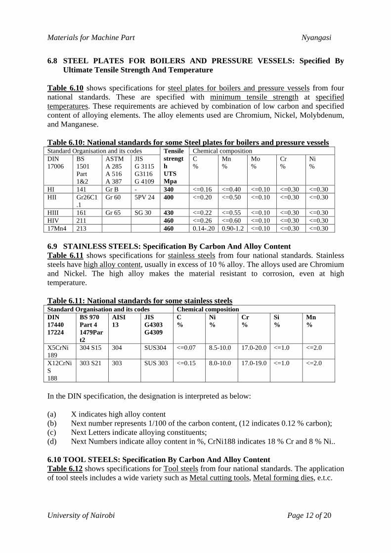
6.8 STEEL PLATES FOR BOILERS AND PRESSURE VESSELS: Specified By
Ultimate Tensile Strength And Temperature Table 6.10 shows specifications for steel plates for boilers and pressure vessels from four national standards. These are specified with minimum tensile strength at specified temperatures. These requirements are achieved by combination of low carbon and specified content of alloying elements. The alloy elements used are Chromium, Nickel, Molybdenum, and Manganese. Table 6.10: National standards for some Steel plates for boilers and pressure vessels Standard Organisation and its codes Chemical composition DIN 17006
BS 1501 Part 1&2
ASTM A 285 A 516 A 387
JIS G 3115 G3116 G 4109
Tensile strength UTS Mpa
C %
Mn %
Mo %
Cr %
Ni %
HI 141 Gr B - 340 <=0.16 <=0.40 <=0.10 <=0.30 <=0.30 HII Gr26C1
.1 Gr 60 5PV 24 400 <=0.20 <=0.50 <=0.10 <=0.30 <=0.30
HIII 161 Gr 65 SG 30 430 <=0.22 <=0.55 <=0.10 <=0.30 <=0.30 HIV 211 460 <=0.26 <=0.60 <=0.10 <=0.30 <=0.30 17Mn4 213 460 0.14-.20 0.90-1.2 <=0.10 <=0.30 <=0.30 6.9 STAINLESS STEELS: Specification By Carbon And Alloy Content Table 6.11 shows specifications for stainless steels from four national standards. Stainless steels have high alloy content, usually in excess of 10 % alloy. The alloys used are Chromium and Nickel. The high alloy makes the material resistant to corrosion, even at high temperature. Table 6.11: National standards for some stainless steels Standard Organisation and its codes Chemical composition DIN 17440 17224
BS 970 Part 4 1479Part2
AISI 13
JIS G4303 G4309
C %
Ni %
Cr %
Si %
Mn %
X5CrNi 189
304 S15 304 SUS304 <=0.07 8.5-10.0 17.0-20.0 <=1.0 <=2.0
X12CrNiS 188
303 S21 303 SUS 303 <=0.15 8.0-10.0 17.0-19.0 <=1.0 <=2.0
In the DIN specification, the designation is interpreted as below: (a) X indicates high alloy content (b) Next number represents 1/100 of the carbon content, (12 indicates 0.12 % carbon); (c) Next Letters indicate alloying constituents; (d) Next Numbers indicate alloy content in %, CrNi188 indicates 18 % Cr and 8 % Ni.. 6.10 TOOL STEELS: Specification By Carbon And Alloy Content Table 6.12 shows specifications for Tool steels from four national standards. The application of tool steels includes a wide variety such as Metal cutting tools, Metal forming dies, e.t.c.
University of Nairobi Page 12 of 20

Materials for Machine Part Nyangasi
Table 6.12: National standards for some Tool steels Standard Organisation and its codes Chemical composition VDE h Wbl 90-150,250,320
BS 4659
ASTM A 686 A 681 A 600
JIS G4401
C %
Cr %
Mo %
W %
V %
Si %
Mn %
C80 W1
BW1 (A-C)
W1 SK1- SK7
0.60-1.40
- - - - 0.10-0.40
0.10-0.40
BW2 W2 0.85-1.40
- - - 0.15- 0.35
0.10- 0.40
0.10-0.40
105WCr6
BO1 O1 SKS31 0.85- 1.00
0.40- 0.60
- -0.40 -0.30 -0.50 1.00- 1.40
90MnV8
BO2 O2 0.85- 0.96
- - - 0.20 -0.50 1.40- 2.00
60CrV7
B31 S1 SKS41 0.35-0.65
1.00-1.80
- 1.50-3.00
0.15-0.30
-0.60 -0.70
BA2 A2 SKD12
0.95-1.05
4.75-5.50
0.90-1.40
- 0.15-0.50
-0.40 -1.0
X165CrMoV12
BD2 D2 1.4-1.9 11-13 0.6-1.2 - -1.10 -0.60 -0.60
X38Cr MoV51
BH H11 SKD6 0.32-0.42
4.75-5.25
1.00-1.50
- 0.30 0.85-1.1
-0.50
Tool steels are therefore primarily high carbon steels in the range of 0.6 to 1.9 % carbon. Some tool steels are therefore plain carbon, while the majority are alloy steels. For example, the material designated BS 4659 BW1 (A-C) is a plain carbon steel, while BS 4659 BW2 includes a small percentage of Vanadium. Vanadium and Tungsten serve to increase the hardness. Other alloys such as Chromium and Nickel modify properties such as strength, ductility toughness, and response to heat treatment, 6.11 EXAMPLE OF MATERIAL SELECTION FOR A CENTRIFUGAL PUMP In Table 6.12, an example is shown of one pump design (KSB Etanorm6 pump series), which is produced in a variety of materials so as to satisfy varying environmental conditions such as wear from particles in pumped liquid, resistance to corrosive environment, strength, e.t.c. Materials used for various pump parts include:
1) Grey cast iron GG 2) Grey cast iron GG-25 3) Nodular cast iron GGG-40.3 4) Tin Bronze G-CuSn10 5) Red Bronze G-CuPb10Sn 6) Tempering steel St 60/45 7) Chrome Molybdenum steel 1.4122 8) Chrome Nickel Molybdenum steel 1.4462 9) Chrome Nickel Molybdenum steel 1.4571 10) Cast Chrome Nickel Molybdenum steel 1.4408 11) Cast Chrome Nickel Molybdenum steel 1.4462
6 Extracted from KSB Etanorm Product Sheet
University of Nairobi Page 13 of 20

Materials for Machine Part Nyangasi
Table 6.12: Material selection: Example from KSB Etanorm Pump Series Material used for each part in each pump designation PART
Etanorm G Etanorm M Etanorm B Etanorm S Etanorm C Volute casing
Grey cast iron GG-25
Grey cast iron GG-25
Tin Bronze G-CuSn10
Nodular cast iron GGG-40.3
Cast Chrome Nickel Molybdenum steel 1.4408
Discharge cover
Grey cast iron GG-25
Grey cast iron GG-25
Tin Bronze G-CuSn10
Nodular cast iron GGG-40.3
Cast Chrome Nickel Molybdenum steel 1.4408
Impeller Grey cast iron GG-25
Tin Bronze G-CuSn10
Tin Bronze G-CuSn10
Grey cast iron GG-25
Cast Chrome Nickel Molybdenum steel 1.4408
Casing wear rings
Grey cast iron GG
Grey cast iron GG /Red Bronze G-CuPb10Sn
Red Bronze G-CuPb10Sn
Grey cast iron GG
Chrome Nickel Molybdenum steel 1.4408
Shaft Tempering steel St 60/45
Tempering steel St 60/45
Chrome Nickel Molybdenum steel 1.4462
Tempering steel St 60/45
Cast Chrome Nickel Molybdenum steel 1.4462
Shaft sleeve Chrome Nickel Molybdenum steel 1.4571
Chrome Nickel Molybdenum steel 1.4571
Chrome Nickel Molybdenum steel 1.4571
Chrome Nickel Molybdenum steel 1.4571
Chrome Nickel Molybdenum steel 1.4571
Shaft protecting sleeve
Chrome Molybdenum steel 1.4122
Chrome Molybdenum steel 1.4122
Chrome Nickel Molybdenum steel 1.4571
Chrome Molybdenum steel 1.4122
Chrome Nickel Molybdenum steel 1.4571
Bearing bracket
Grey cast iron GG-25
Grey cast iron GG-25
Grey cast iron GG-25
Grey cast iron GG-25
Grey cast iron GG-25
6.12 HEAT TREATMENT OF STEELS Heat treatment given to steel may be roughly classified into non-quenching and quenching types: (a) Non-quenching types These types of heat treatment are usually applied as preliminary or intermediate treatments used to condition the steel for further processing and heat treating. They include:
(1) Stress relieving This is performed to relieve stresses caused by cold working. Process consists of heating to just below the critical temperature, followed by cooling slowly, usually in air. Stresses relieved include those caused by straightening and machining. (2) Annealing This is an intermediate process used to reduce the hardness caused by casting and forging steels above 0.35 % carbon, so that the parts may thereafter be machined. The process consists of heating the steel above the critical temperature followed by cooling slowly in a furnace.
University of Nairobi Page 14 of 20

Materials for Machine Part Nyangasi
(3) Normalising This is applied in parts that have been rolled, or forged, to refine the grain structure so that it may subsequently respond uniformly to heat treatment. The process consists of heating the steel to above the critical temperature and cooling in still air.
(b) Quenching Quenching types of heat treatment is given to steel to impart the final physical properties desired for the part. The heat treatment types include:
(1) Through hardening This is the most common heat treatment of steel, and involves heating the part to above the critical temperature, followed by quenching and tempering. (2) Tempering Tempering consists of re-heating the steel to a temperature below the critical point and then cooling it at a pre-determined rate. The purpose is to reduce or draw back the as quenched hardness. (3) Case hardening This involves hardening the surface layer of the part by the addition of carbon or nitrogen. After the addition of carbon, the part is then heated to above the critical temperature and then quenched. The purpose is to create a hard case on the part A hardened case of depth ranging from 0.25 to 2.5 mm. can be produced in this way. (4) Surface hardening This is a form of case hardening, but in which the surface of the steel is heated directly to a point above the critical temperature and then quenched. It is usually performed on steels with a sufficiently high carbon content such as 0.30 % carbon and above. The steel is therefore able to respond to heating and quenching without the preliminary procedure of addition of carbon used in case hardening.
University of Nairobi Page 15 of 20

Materials for Machine Part Nyangasi
6.5 CAST IRON Cast iron can be produced in three forms, namely: (a) Grey cast iron; (b) Malleable cast iron;
(c) Ductile (nodular) cast iron; (d) White iron.
All the three forms of cast iron are alloys of iron and carbon, with carbon content by weight ranging from 2 % to 4 %. Cast irons also contain a high amount of silicon, often in excess of 1 %. Other elements that occur in small quantities ( often less than 1 %) are Sulphur, Manganese, and Phosphorus. 6.5.1 Grey cast iron Grey cast iron is obtained when casting conditions combine with the chemical composition to yield a product in which the carbon occurs in the form of flakes of graphite. These thin flakes of graphite are distributed evenly through the ferrite and cause the appearance of the micro-structure to darken, hence the name grey cast iron. Grey cast iron is widely used. In most national standards, it is classified according to its tensile strength, as shown in Table 6.2 with the example from British Standard specifications. Table 6.2:Mechanical properties of grey cast iron (Tensile strength corresponds to the BS Grade)
Grade Designation (British Standard Specification) Mechanical Properties 150 180 220 260 300 350 400
Tensile strength (Mpa.) 150 180 220 260 300 350 400 Compressive strength (Mpa.) 587 663 766 868 970 1097 1225 Shear strength (Mpa.) 176 222 284 346 407 484 562 Endurance limit (Mpa.) 71 82 96 111 125 143 161 Young's modulus (Gpa.) 71-96 79-104 89-114 100-124 110-135 124-147 137-160 Modulus of rigidity(Gpa.) 29-40 32-42 36-45 40-48 43-51 48-55 53-58 Hardness (HB) 160 176 196 216 236 261 286 Other national standards apply a classification scheme similiar to that shown in Table 6.2. For example, grey cast iron Grade FG 150 in the Indian standards is equivalent to Grade 150 in the British standards. (a) Advantages of Grey Cast Iron (i) Availability; (ii) Low cost for volume production; (iii) Amenability to production of complex shapes, thereby reducing the requirements for
machining operations; (iv) High compressive strength compared to steel. Therefore preferred for compressive
loading situations; (v) Ability to damp vibrations; (vi) Resistance to wear; (vii) Resistance to corrosion (relative to untreated steel).
University of Nairobi Page 16 of 20
Materials for Machine Part Nyangasi
(b) Disadvantages (i) Low tensile strength, compared to steel; (ii) Section size sensitivity i.e. Tensile strength decreases as section size increases; (iii) Brittleness. Little plastic deformation before fracture, and no yield point. Cast iron is
therefore subject to brittle failure, and therefore not suitable for applications in which failure by yielding, rather than sudden fracture would be preferred.
(iv) Low impact resistance; (v) Poor machinability, compared to steel; (c) Applications (i) Machine tool beds, frames, guides, pulleys, hydraulic cylinders e.t.c; (ii) I.C. Engine parts, such as cylinder blocks, cylinder heads, crank-cases, exhaust
manifolds, e.t.c; (iii) Flywheels, brake drums, brake shoes e.t.c; (iv) Hydraulic pipes, pipe fittings, valve bodies e.t.c. 6.5.2 White cast iron White cast iron is a product in which the carbon is combined with iron to form Cementite ( a compound of iron Fe, and carbon C), with no free graphite present. The product is obtained by a specified combination of casting process, and chemical composition of the melt. Cementite is very hard, and white cast iron therefore also displays this property. White cast iron is therefore very hard, brittle, and difficult to machine. 6.5.3 Malleable cast iron Malleable iron is made by the heat treatment of white cast iron. Malleable cast iron is obtained, when white cast iron, within a certain composition range, is annealed. The annealing process breaks down the Cementite, and frees the carbon from the Cementite. The free carbon then reconstitutes itself into graphite. However, instead of the free graphite taking the form of flakes, as in grey cast iron, the annealing process causes it to form rosettes of free graphite. This transformation of graphite into form of rosettes changes the properties of the resultant material from hard and brittle, to softer and ductile. The tensile strength of the material is also increased. Malleable iron therefore has properties somewhat similar to low carbon steel, but with the added advantage of easier casting. The significant properties are the combination of ductility, strength, and castability. The heat treatment process required to transform white cast iron, into malleable iron is however long, taking a period of days. The product is therefore expensive to produce.
University of Nairobi Page 17 of 20

Materials for Machine Part Nyangasi
6.5.4 Ductile (Nodular) cast iron The microstructure of Ductile iron is similar to that of malleable iron, to the extent that it also contains free graphite, although in nodular form. The material is therefore sometimes referred to as nodular iron. The difference between malleable and ductile iron is in the process of production. Instead of the lengthy and expensive heat treatment given to white cast iron to yield malleable iron, ductile iron is produced in the as cast condition, and thereafter it is given a simpler heat treatment of 1 hour annealing. The transformation of free graphite from flakes to nodules is achieved by innoculating the cast iron melt with cesium and magnesium. These additives cause the carbon in the melt to form nodules of free graphite during cooling and solidification. Ductile iron, in the as cast condition, therefore exhibits properties similiar to malleable iron, after it is given a simpler heat treatment of 1 hour annealing. 6.13 COPPER AND ITS ALLOYS 6.14 ALUMINUM AND ITS ALLOYS References 1) Mechanical properties of Metallic materials, Beaumont, J. 2) Mechanical Behaviour of Engineering Materials, Mariu, Joseph. 3) Strength of Materials, VOL. II, Timoshenko, S. 4) Design of machine elements, Bhandari, V.B., TATA McGraw-Hill, 1994. 5) Mechanical Engineering Design, Shigley, J., McGraw-Hill International Edition, 1986 6) Drawing and design, Bhandari, V.B., University of Dar-es-salaam, 1983.
University of Nairobi Page 18 of 20

Materials for Machine Part Nyangasi
APPENDIX A7: MECHANICAL PROPERTIES OF SOME STEELS Material British
Standard8Production process
Maximum section size, mm.
Yield Strength Mpa
Tensile Strength, Mpa
Elongation %
Hardness Number, HB
152 215 430 22 126-179 HR9
254 200 400 20 116-170 13 385 530 12 154
0.20C 070M20
CD10
76 340 430 14 125 152 245 490 20 143-192 HR 254 230 460 19 134-183 13 470 600 10 174 CD 63 385 530 12 154
0.30C 080M30
H&T11 63 385 550-700 13 152-207 HR 150 280 550 16 152-207 CD 63 430 570 10 165
0.40C 080M40
H&T 63 385 625-775 16 179-229 HR 150 310 620 14 179-229 CD 63 510 650 10 188
0.50C 080M50
H&T 150 430 625-775 11 179-229 100 525 700-850 17 202-255 1Cr 530M40 H&T 29 680 850-1000 13 248-302 150 525 700-850 17 202-255 1.5MnMo 605M36 H&T 29 755 925-1075 12 269-331 152 525 700-850 17 202-255 102 585 770-930 15 223-277 64 680 850-1000 13 248-302
1.25NiCr 640M40 H&T
29 755 930-1080 12 269-331 64 755 930-1080 12 269-331 3NiCr 653M31 H&T 680 850-1000 12 248-302 150 525 700-850 17 201-255 1CrMo 708M40 H&T 13 940 1075-1225 12 311-375 152 680 850-1000 13 269-331 3CrMo 722M24 H&T 755 930-1080 12 269-331 150 755 925-1075 12 269-331 850 1000-1150 12 293-352
2.5NiCrMo 826M40 H&T
1020 1150-1300 10 341-401 254 650 850-1000 13 248-302 152 680 850-1000 12 248-302
3NiCrMo 830M31 H&T
64 940 1080-1240 11 311-375 152 525 690-850 17 201-255 64 680 850-1000 13 248-302
1.5MnNiCrMo 945M38 H&T
29 850 1000-1160 12 293-352
7 Shigley, Joseph E., Mechanical Engineering Design, pp. 664, McGraw-Hill Inc., 1986 8 British Standards Institution, BS 970: Part 1: 1983 9 HR-Hot rolled and normalised 10 CD-Cold drawn 11 H&T-Hardened and tempered
University of Nairobi Page 19 of 20

Materials for Machine Part Nyangasi
APPENDIX B: STEEL APPLICATION AND HEAT-TREATING GUIDE12
Low-Carbon Medium-Carbon High-Carbon Plain Carbon Or Lean Alloy
Alloy Plain Carbon Or Lean Alloy
Medium Alloy
Rich Alloy
USE
OR
PART C 1020 C 1117
A2315-20 3115-20 4615-20 5120 8620
C1040-50 A3140-50 4140-50 5145 8640-50 8740-50 6145
A 4340 3250
Oil Hard-ening Tool Steel
Water Hard-ening Tool Steel
Arbors N,T T T Armature shafts T T T Axles C C N,T,A, S,T, T T Ball races C S T T T Bolts and studs T,A T T Bushings C C T Cams C T T Camshaft C C T T Cant dogs T Chain Links T Chain Pins C C Chuck Jaws C T T Chuck screws N,A T Clutches T T Collets T T Connecting Rods T T Crankshafts N,S,A S,T S,T Drift Pins N T Engine bolts C C N,T T Gears C C N,S,T,A S,T S,T T Guide Pins T T Mandrels C C T Pinions C C N,S,T S,T S,T T Pins C T T Pistons C T Pump Shafts N,T,A T Rollers C C Rolls C C S S,T S,T T T Lead Screws N,A T Set Screws T T Spindles C C S,T,A, S,T, S,T T T Stay Bolts N A Thrust washers C T Turbine Shafts N,T,A T Turnbuckles T T U bolts T T Universal Joint Pins C C Universal joint bodies N,T,A, T T Worm Gears C C S,T S,T N=Normalised; C= Case-hardened; S= Surface-hardened; T= Through-hardened; A= As-rolled
12 pp. 10, ASME Handbook, Metals Engineering-Processes, McGraw-Hill Book Company, 1958
University of Nairobi Page 20 of 20