Embed Size (px)
DESCRIPTION
Gas lift
Citation preview
Gas lift Modelling and Design Ex 6 1
Example 6
FloSystem User Course
Example 6
Gas lift Modelling and Design

Gas lift Modelling and Design Ex 6 2
Summary of Work-Flow for Gas Lift Design
• Check if well is naturally flowing
• Design with Deepest Point to get basic parameters of design
• Sensitivity to changing reservoir performance for bracketing envelope
• Select design parameters, valve type and set design margins
• Do Spacing calculations
• Do Sizing options - edit required changes
• Check un-loading at different conditions - use Re-Calc. Modify design if required
• Predict performance with real valves installed
Gas lift Modelling and Design Ex 6 3
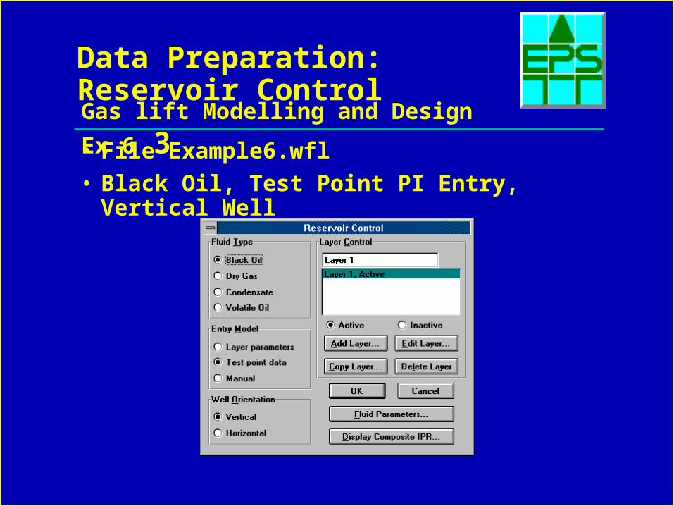
Data Preparation: Reservoir Control
• File Example6.wfl
• Black Oil, Test Point PI Entry, Vertical Well
Gas lift Modelling and Design Ex 6 4
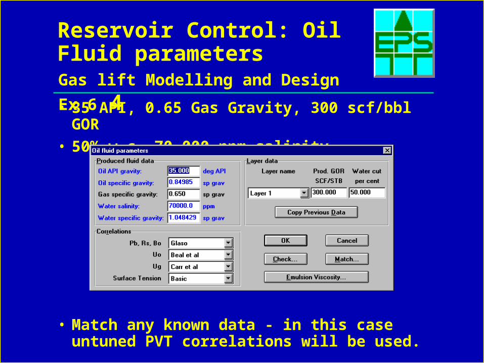
Reservoir Control: Oil Fluid parameters
• 35 API, 0.65 Gas Gravity, 300 scf/bbl GOR
• 50% w.c, 70,000 ppm salinity
• Match any known data - in this case untuned PVT correlations will be used.
Gas lift Modelling and Design Ex 6 5
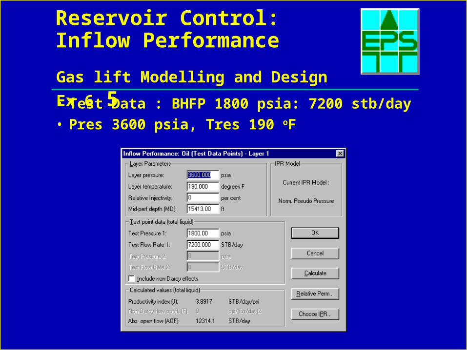
Reservoir Control: Inflow Performance
• Test Data : BHFP 1800 psia: 7200 stb/day
• Pres 3600 psia, Tres 190 oF
Gas lift Modelling and Design Ex 6 6
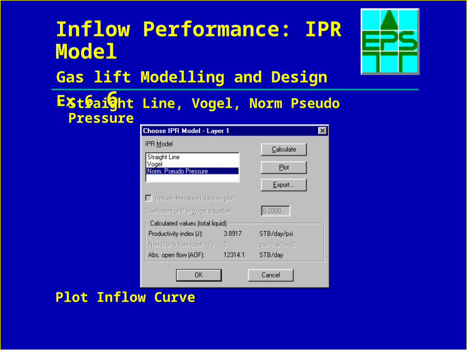
Inflow Performance: IPR Model
• Straight Line, Vogel, Norm Pseudo Pressure
Plot Inflow Curve
Gas lift Modelling and Design Ex 6 7
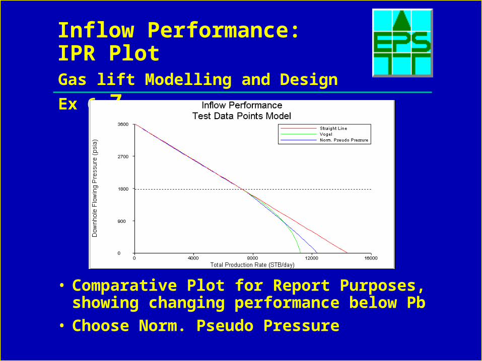
Inflow Performance:IPR Plot
• Comparative Plot for Report Purposes, showing changing performance below Pb
• Choose Norm. Pseudo Pressure
Gas lift Modelling and Design Ex 6 8
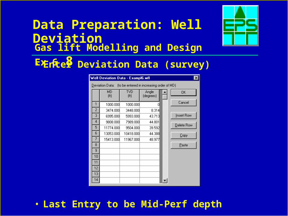
Data Preparation: Well Deviation
• Enter Deviation Data (survey)
• Last Entry to be Mid-Perf depth
Gas lift Modelling and Design Ex 6 9
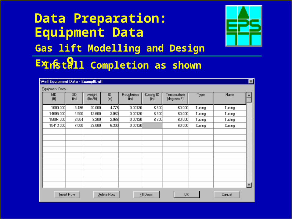
Data Preparation: Equipment Data
• Install Completion as shown
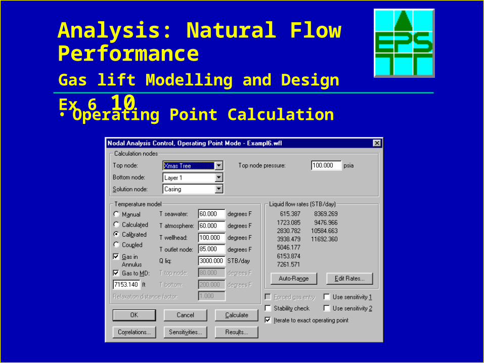
Gas lift Modelling and Design Ex 6 10
Analysis: Natural Flow Performance
• Operating Point Calculation
Gas lift Modelling and Design Ex 6 11
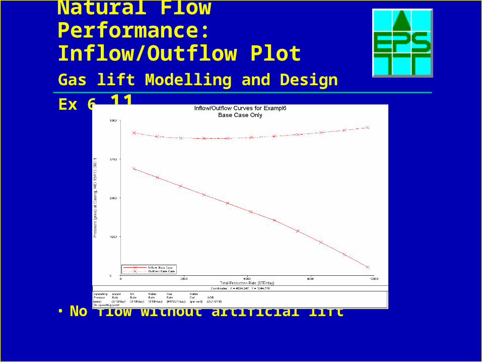
Natural Flow Performance: Inflow/Outflow Plot
• No flow without artificial lift
Gas lift Modelling and Design Ex 6 12
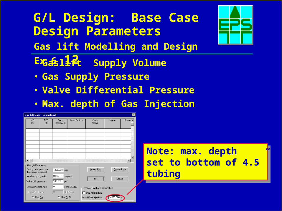
G/L Design: Base Case Design Parameters
• Gaslift Supply Volume
• Gas Supply Pressure
• Valve Differential Pressure
• Max. depth of Gas Injection
Note: max. depthset to bottom of 4.5”tubing
Note: max. depthset to bottom of 4.5”tubing
Gas lift Modelling and Design Ex 6 13
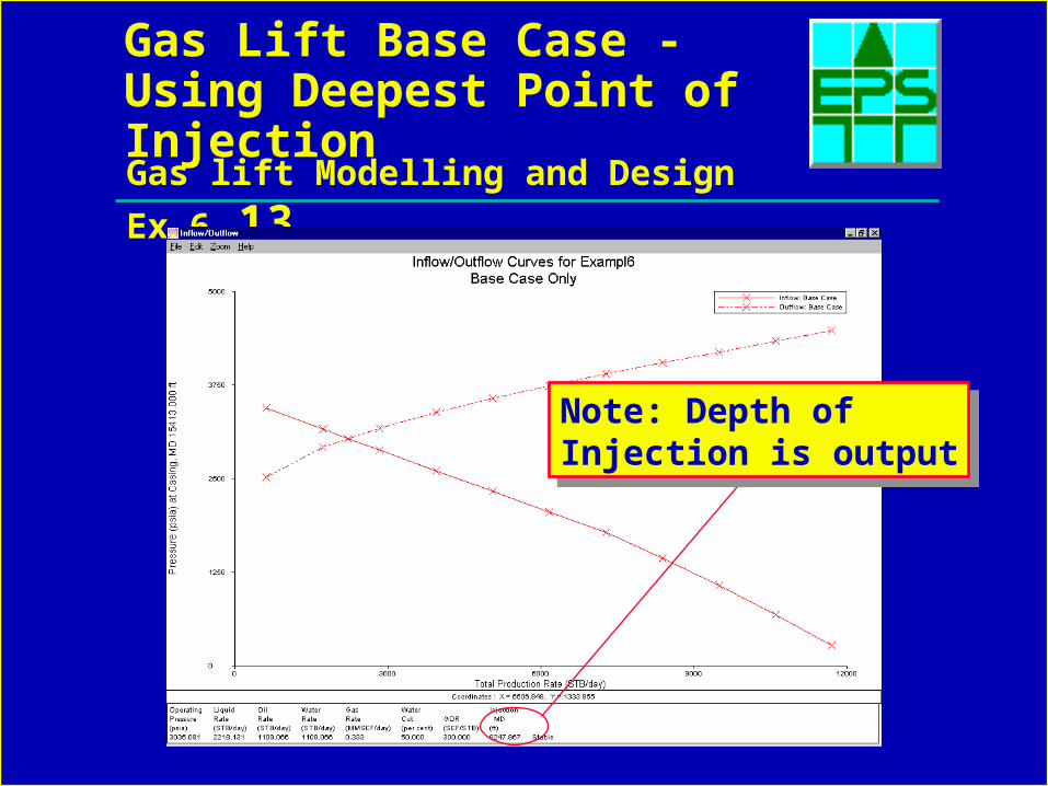
Gas Lift Base Case - Using Deepest Point of Injection
Note: Depth of Injection is output
Note: Depth of Injection is output
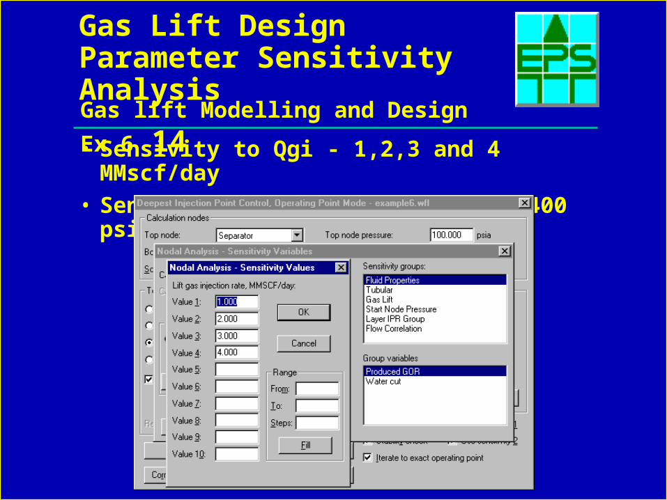
Gas lift Modelling and Design Ex 6 14
Gas Lift Design Parameter Sensitivity Analysis
• Sensivity to Qgi - 1,2,3 and 4 MMscf/day
• Sensitivity to CHP - 1000,1200,1400 psia
Gas lift Modelling and Design Ex 6 15
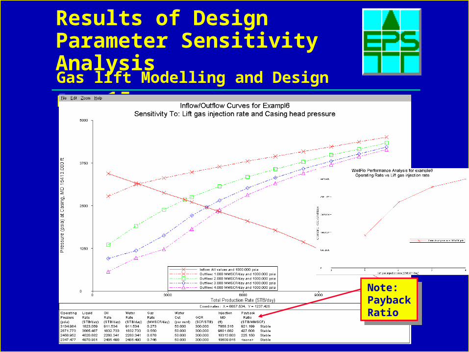
Results of Design Parameter Sensitivity Analysis
Note: PaybackRatio
Note: PaybackRatio
Gas lift Modelling and Design Ex 6 16
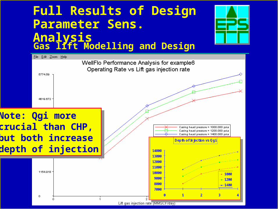
Full Results of Design Parameter Sens. Analysis
Note: Qgi more crucial than CHP, but both increasedepth of injection
Note: Qgi more crucial than CHP, but both increasedepth of injection
Gas lift Modelling and Design Ex 6 17
Reservoir Decline Sensitivity Analysis
• Target Gas Lift CHP 1200 psia, Qgi 2.5 MMscf/day
• Reservoir Depleted 800 psi
• Increasing Watercut: 50% to 75% 90%
• Set Qgi to 2.5 MMscf/day and CHP to 1200 psia.
• Run a sensistivity analysis with layer pressures of 3600 and 2800 psia for sensitivity 1 and water-cuts of 50,75 and 90% for sensitivity 2.
still using deepest point of injection
Gas lift Modelling and Design Ex 6 18
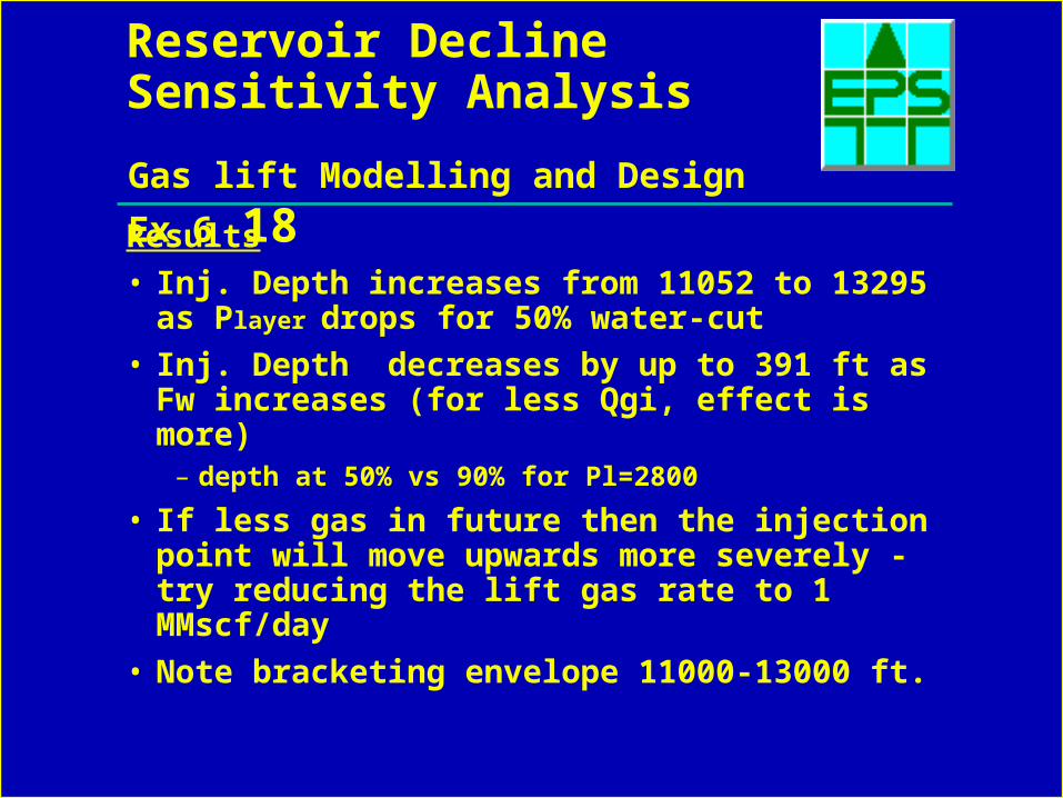
Reservoir Decline Sensitivity Analysis
Results
• Inj. Depth increases from 11052 to 13295 as Player drops for 50% water-cut
• Inj. Depth decreases by up to 391 ft as Fw increases (for less Qgi, effect is more)– depth at 50% vs 90% for Pl=2800
• If less gas in future then the injection point will move upwards more severely -try reducing the lift gas rate to 1 MMscf/day
• Note bracketing envelope 11000-13000 ft.
Gas lift Modelling and Design Ex 6 19
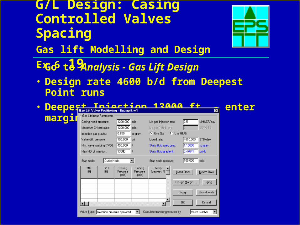
G/L Design: Casing Controlled Valves Spacing
• Go to Analysis - Gas Lift Design
• Design rate 4600 b/d from Deepest Point runs
• Deepest Injection 13000 ft. - enter margins
Gas lift Modelling and Design Ex 6 20
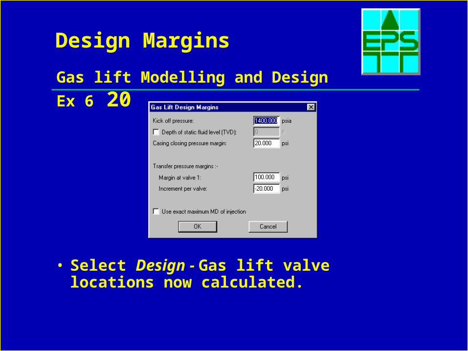
Design Margins
• Select Design - Gas lift valve locations now calculated.
Gas lift Modelling and Design Ex 6 21
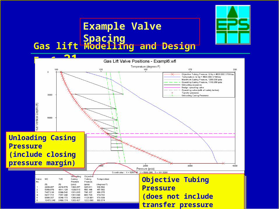
Example Valve Spacing
Unloading Casing Pressure (include closing pressure margin)
Unloading Casing Pressure (include closing pressure margin)
Objective Tubing Pressure (does not include transfer pressure margins)
Objective Tubing Pressure (does not include transfer pressure margins)
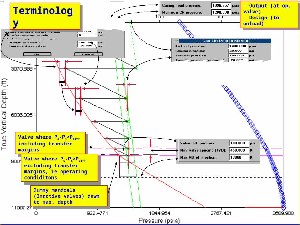
Gas lift Modelling and Design Ex 6 22
Valve where Pc-Pt>Pdiff including transfer margins
Valve where Pc-Pt>Pdiff including transfer margins
Valve where Pc-Pt>Pdiff excluding transfer margins, ie operating condiditons
Valve where Pc-Pt>Pdiff excluding transfer margins, ie operating condiditons
Dummy mandrels (Inactive valves) down to max. depth
Dummy mandrels (Inactive valves) down to max. depth
- Output (at op. valve)- Design (to unload)
- Output (at op. valve)- Design (to unload)TerminologyTerminology
Gas lift Modelling and Design Ex 6 23
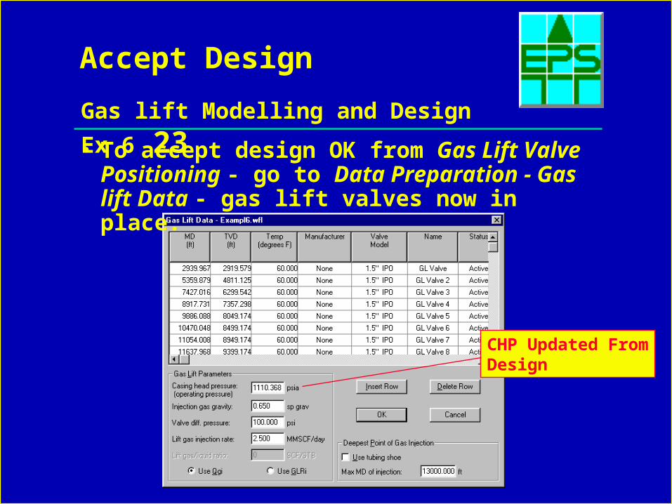
Accept Design
• To accept design OK from Gas Lift Valve Positioning - go to Data Preparation - Gas lift Data - gas lift valves now in place.
CHP Updated FromDesign
Gas lift Modelling and Design Ex 6 24
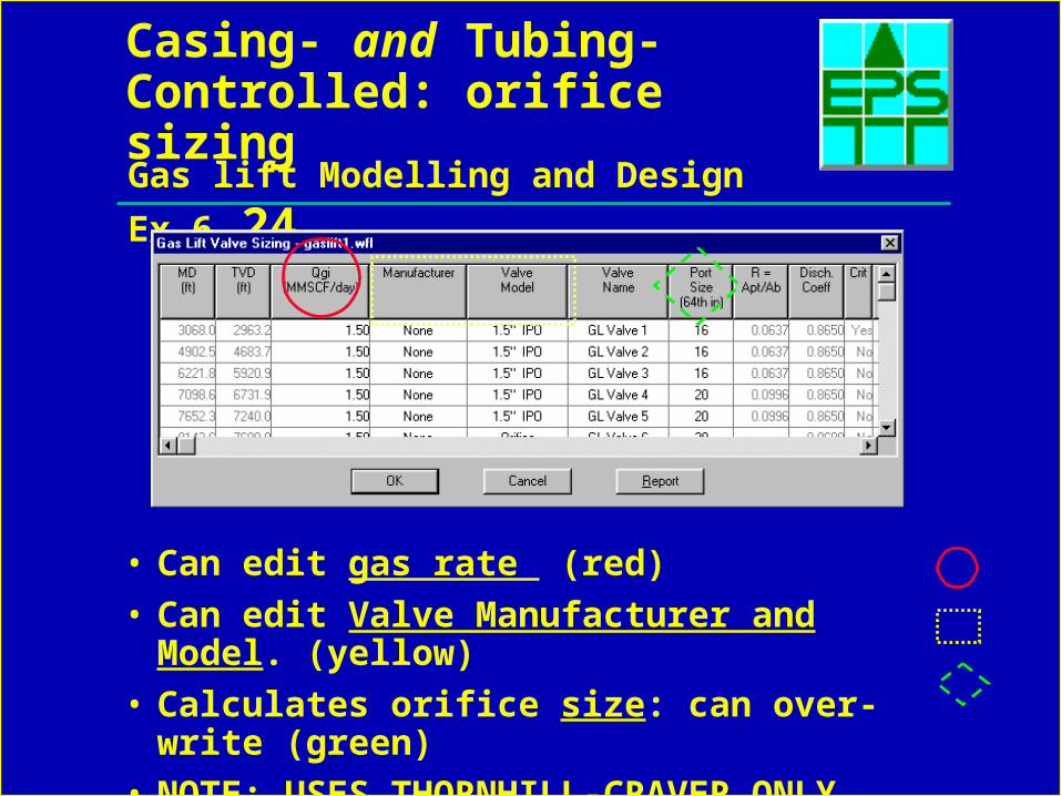
Casing- and Tubing-Controlled: orifice sizing
• Can edit gas rate (red)
• Can edit Valve Manufacturer and Model. (yellow)
• Calculates orifice size: can over-write (green)
• NOTE: USES THORNHILL-CRAVER ONLY
Gas lift Modelling and Design Ex 6 25
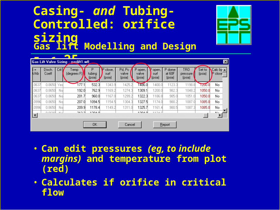
Casing- and Tubing-Controlled: orifice sizing
• Can edit pressures (eg, to include margins) and temperature from plot (red)
• Calculates if orifice in critical flow
Gas lift Modelling and Design Ex 6 26
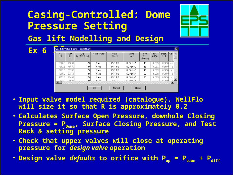
Casing-Controlled: Dome Pressure Setting
• Input valve model required (catalogue). WellFlo will size it so that R is approximately 0.2
• Calculates Surface Open Pressure, downhole Closing Pressure = PDome, Surface Closing Pressure, and Test Rack & setting pressure
• Check that upper valves will close at operating pressure for design valve operation
• Design valve defaults to orifice with Pop = Ptube + Pdiff
Gas lift Modelling and Design Ex 6 27
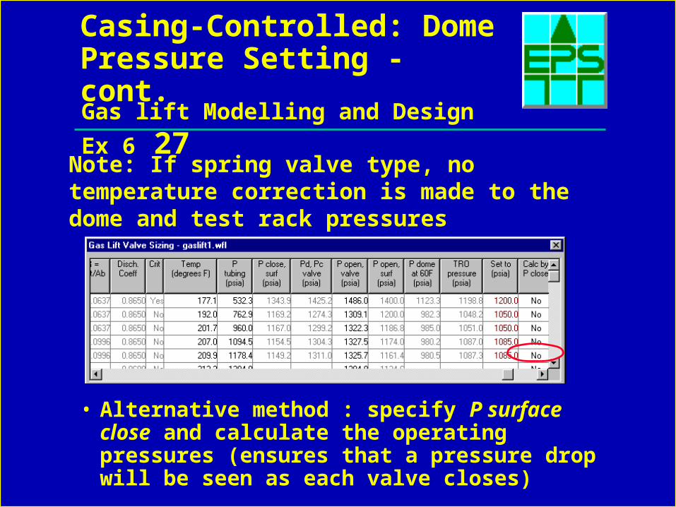
Casing-Controlled: Dome Pressure Setting - cont.
• Alternative method : specify P surface close and calculate the operating pressures (ensures that a pressure drop will be seen as each valve closes)
Note: If spring valve type, no temperature correction is made to the dome and test rack pressures
Gas lift Modelling and Design Ex 6 28
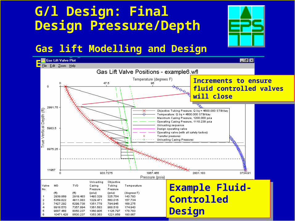
G/l Design: Final Design Pressure/Depth
Example Fluid-Controlled Design
Example Fluid-Controlled Design
Increments to ensure fluid controlled valves will close
Increments to ensure fluid controlled valves will close
Gas lift Modelling and Design Ex 6 29
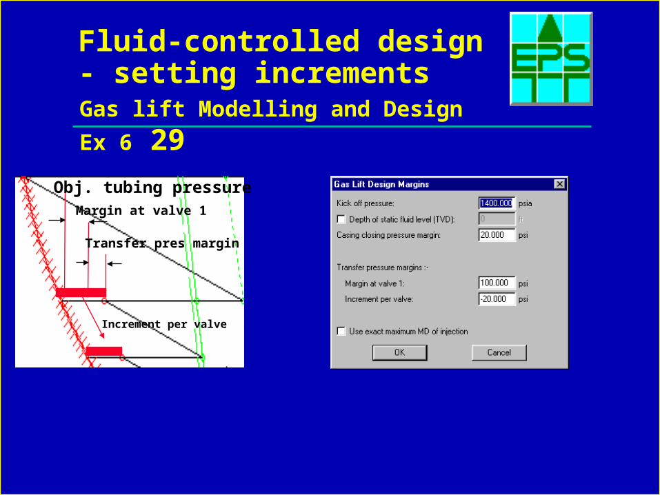
Fluid-controlled design - setting increments
Transfer pres margin
Margin at valve 1
Obj. tubing pressure
Increment per valve
Gas lift Modelling and Design Ex 6 30
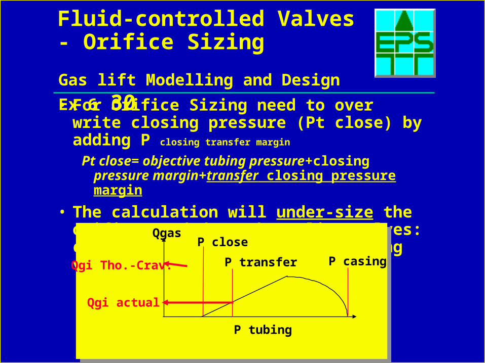
Fluid-controlled Valves - Orifice Sizing
• For Orifice Sizing need to over write closing pressure (Pt close) by adding P closing transfer margin
Pt close= objective tubing pressure+closing pressure margin+transfer closing pressure margin
• The calculation will under-size the orifice needed on throttling valves: consult Gas Lift Company supplying valves
Qgas
P tubing
P transfer
P close
P casing
Qgi actual
Qgi Tho.-Crav.
Gas lift Modelling and Design Ex 6 31
Fluid-controlled Valves - Orifice Sizing
• The casing pressure (Pcasing) is calculated by adding the valve differential pressure:
Pt close + valve differential pressure
• This will give the designer input for the spreadsheet Pt close and P casing– See previous terminology
Gas lift Modelling and Design Ex 6 32
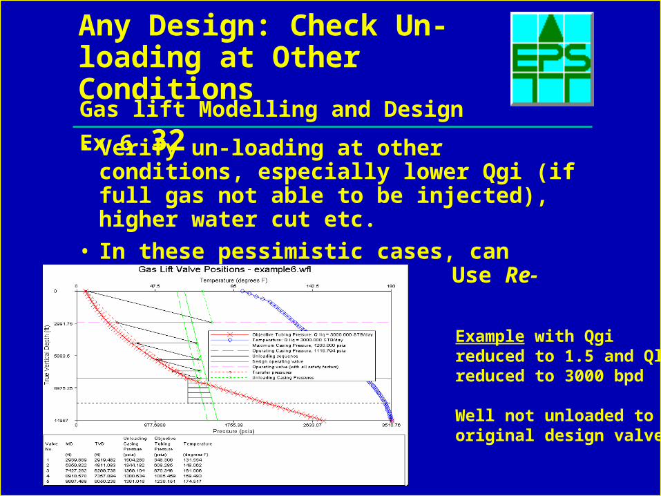
Any Design: Check Un-loading at Other Conditions
• Verify un-loading at other conditions, especially lower Qgi (if full gas not able to be injected), higher water cut etc.
• In these pessimistic cases, can eliminate Design Margins. Use Re-Calculate
Example with Qgi reduced to 1.5 and Qlreduced to 3000 bpd
Well not unloaded tooriginal design valve
Gas lift Modelling and Design Ex 6 33
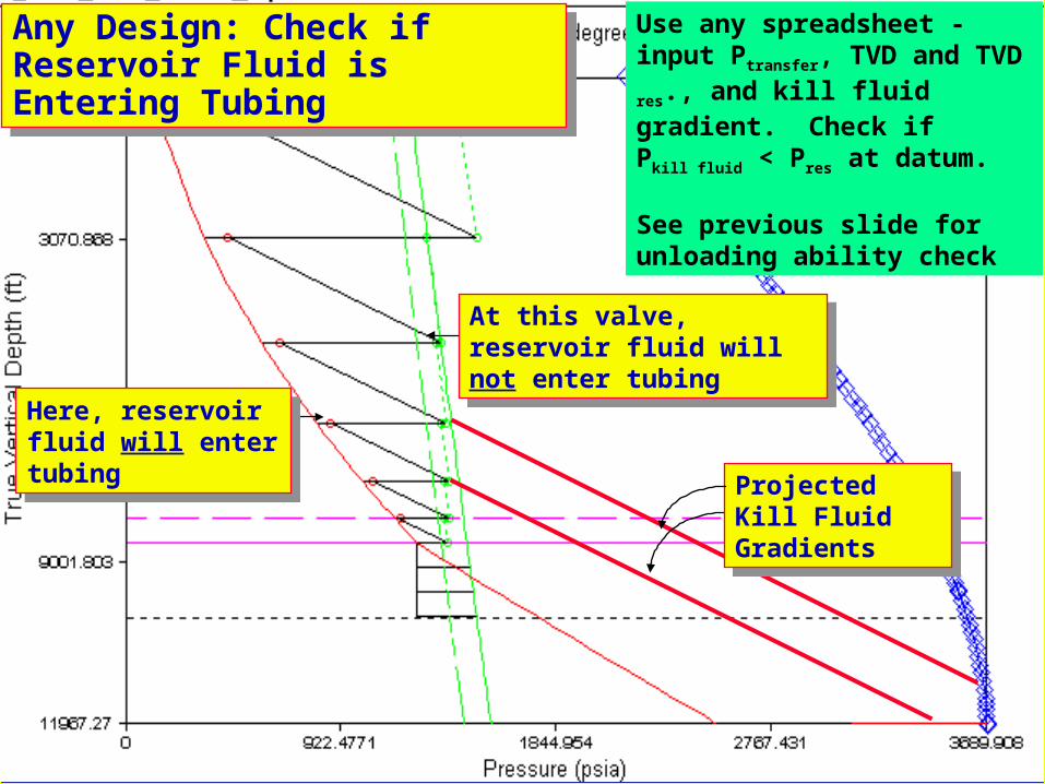
Any Design: Check if Reservoir Fluid is Entering TubingAny Design: Check if Reservoir Fluid is Entering Tubing
Projected Kill Fluid Gradients
Projected Kill Fluid Gradients
At this valve, reservoir fluid will not enter tubing
At this valve, reservoir fluid will not enter tubing
Here, reservoir fluid will enter tubing
Here, reservoir fluid will enter tubing
Use any spreadsheet - input Ptransfer, TVD and TVD res., and kill fluid gradient. Check if Pkill fluid < Pres at datum.
See previous slide for unloading ability check
Gas lift Modelling and Design Ex 6 34
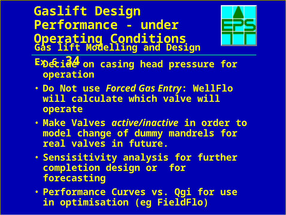
Gaslift Design Performance - under Operating Conditions
• Decide on casing head pressure for operation
• Do Not use Forced Gas Entry: WellFlo will calculate which valve will operate
• Make Valves active/inactive in order to model change of dummy mandrels for real valves in future.
• Sensisitivity analysis for further completion design or for forecasting
• Performance Curves vs. Qgi for use in optimisation (eg FieldFlo)
Gas lift Modelling and Design Ex 6 35
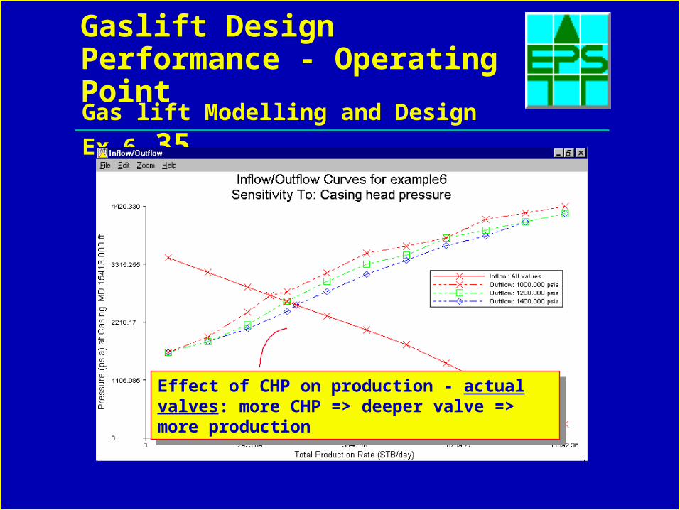
Gaslift Design Performance - Operating Point
Effect of CHP on production - actual valves: more CHP => deeper valve => more production
Effect of CHP on production - actual valves: more CHP => deeper valve => more production
Gas lift Modelling and Design Ex 6 36
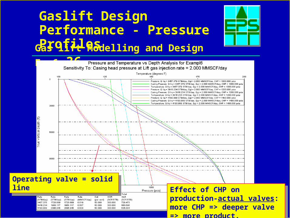
Gaslift Design Performance - Pressure Profiles
Effect of CHP on production-actual valves: more CHP => deeper valve => more product.
Effect of CHP on production-actual valves: more CHP => deeper valve => more product.
Operating valve = solid lineOperating valve = solid line

Gas lift Modelling and Design Ex 6 37
Summary of Work-Flow for Gas Lift Design
• Check if well is naturally flowing
• Design with Deepest Point to get basic parameters of design
• Sensitivity to changing reservoir performance for bracketing envelope
• Select design parameters, valve type and set design margins
• Do Spacing calculations
• Do Sizing options - edit required changes
• Check un-loading at different conditions - use Re-Calc. Modify design if required
• Predict performance with real valves installed