Embed Size (px)
Citation preview

CADtoEarthFor Autodesk Revit
User's GuideApril 29, 2013
Copyright © 2013 AMC Bridge LLC. All rights reserved.
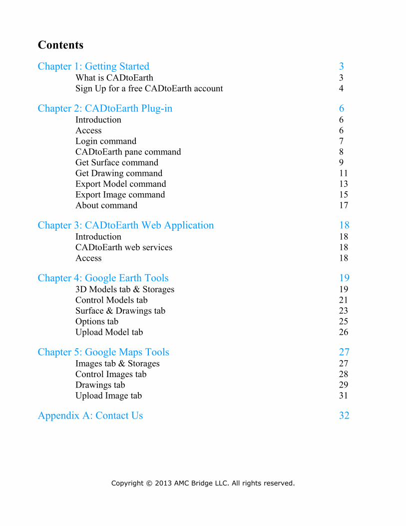
Contents
Chapter 1: Getting Started 3What is CADtoEarth 3Sign Up for a free CADtoEarth account 4
Chapter 2: CADtoEarth Plug-in 6Introduction 6Access 6Login command 7CADtoEarth pane command 8Get Surface command 9Get Drawing command 11Export Model command 13Export Image command 15About command 17
Chapter 3: CADtoEarth Web Application 18Introduction 18CADtoEarth web services 18Access 18
Chapter 4: Google Earth Tools 193D Models tab & Storages 19Control Models tab 21Surface & Drawings tab 23Options tab 25Upload Model tab 26
Chapter 5: Google Maps Tools 27Images tab & Storages 27Control Images tab 28Drawings tab 29Upload Image tab 31
Appendix A: Contact Us 32
Copyright © 2013 AMC Bridge LLC. All rights reserved.
Getting Started
This guidance document describes the formal steps of how to use CADtoEarth plug-in for Autodesk Revit with CADtoEarth web application. It provides a help material which is intended to assist you in usage of all application functions.
What is CADtoEarth
CADtoEarth is a family of innovative add-in applications for the most popular CAD packages, linking modeling environments with Google Earth and Google Maps.
CADtoEarth for Autodesk Revit offers some very exciting capabilities.Here is the partial list of what you can expect:
• Import a section of a surface from Google Earth into a Revit modeling session as a Toposurface.
• Import a pre-drawn sketch from Google Earth into a Revit modeling session.Import the information about building layer from Google Earth.
• Place your 3D structures on the imported Toposurface within a Revit modeling session and then upload them back to Google Earth.
• Perform the similar operations with 2D objects between Revit and Google Maps.
Manage your 3D models in CADtoEarth web application:
• Change altitude, scale, rotate and move your 3D structures.• Choose 3D structures for auto-placement.• Share your 3D structures with other users.• Upload *.kmz models into your personal storage.
Copyright © 2013 AMC Bridge LLC. All rights reserved.
Sign Up for a free CADtoEarth account
It is required to sign up for a CADtoEarth account to be able to link up your CAD environment with Google Earth and Google Maps services.
Note: To simplify the creation of the account you are not required to provide any personal information. However if you tell us your email, it will be possible to recover your account in case of lost or forgotten credentials.
The account is completely free, and you can register one in a few easy steps:
• To register, you will need a web browser and an Internet connection.In the browser address bar type: http://www.cadtoearth.amcbridge.com
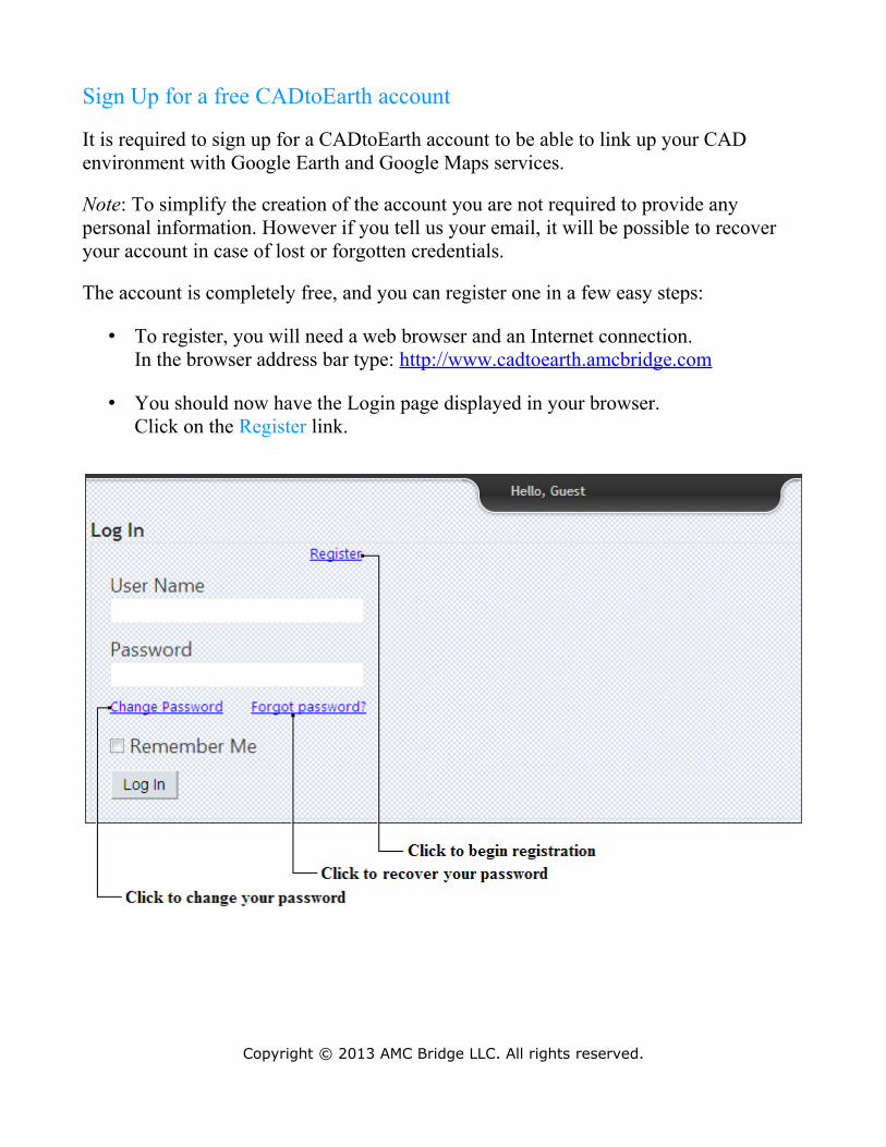
• You should now have the Login page displayed in your browser.Click on the Register link.
Copyright © 2013 AMC Bridge LLC. All rights reserved.
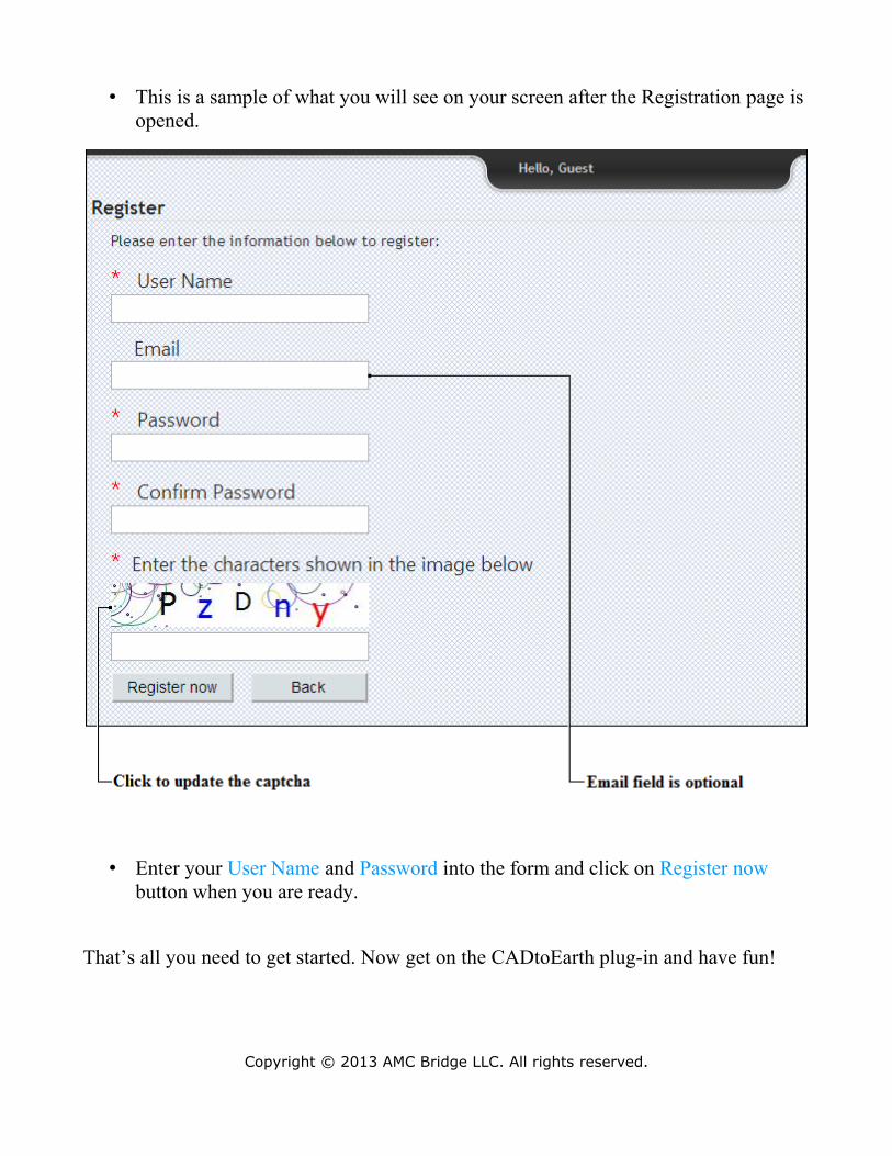
• This is a sample of what you will see on your screen after the Registration page is opened.
• Enter your User Name and Password into the form and click on Register now button when you are ready.
That’s all you need to get started. Now get on the CADtoEarth plug-in and have fun!
Copyright © 2013 AMC Bridge LLC. All rights reserved.
CADtoEarth Plug-in
Introduction
The CADtoEarth plug-in extends the functionality of Autodesk Revit and establishes a bi-directional connection between CAD environment and such virtual globe and map services like Google Earth and Google Maps.
Plug-in features the following functions:• Export of 3D model to Google Earth.• Export of 3D model view and subsequent placement of it onto Google Maps.• Import of the Earth surface from Google Earth, which may be useful for
architecture design purposes if rough data on ground elevations is needed.• Import of the sketched curves from Google Earth and Google Maps, which may
be useful for the object outlines capturing.
Access
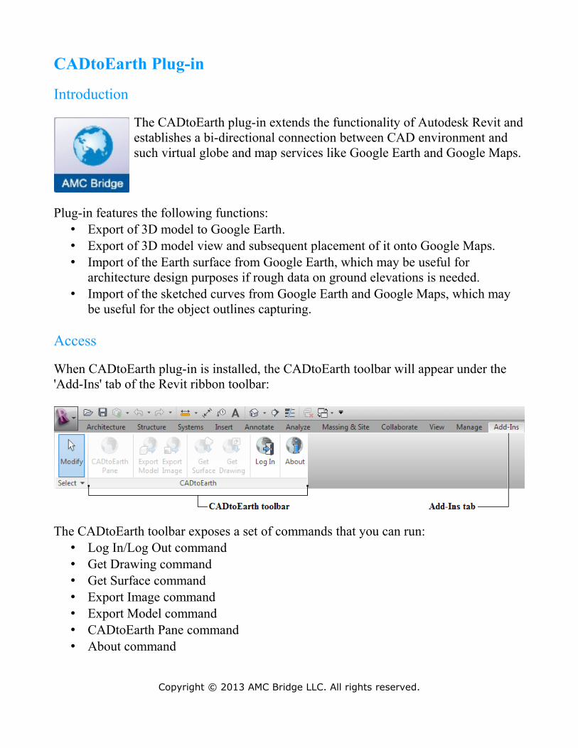
When CADtoEarth plug-in is installed, the CADtoEarth toolbar will appear under the 'Add-Ins' tab of the Revit ribbon toolbar:
The CADtoEarth toolbar exposes a set of commands that you can run:• Log In/Log Out command• Get Drawing command• Get Surface command• Export Image command• Export Model command• CADtoEarth Pane command• About command
Copyright © 2013 AMC Bridge LLC. All rights reserved.
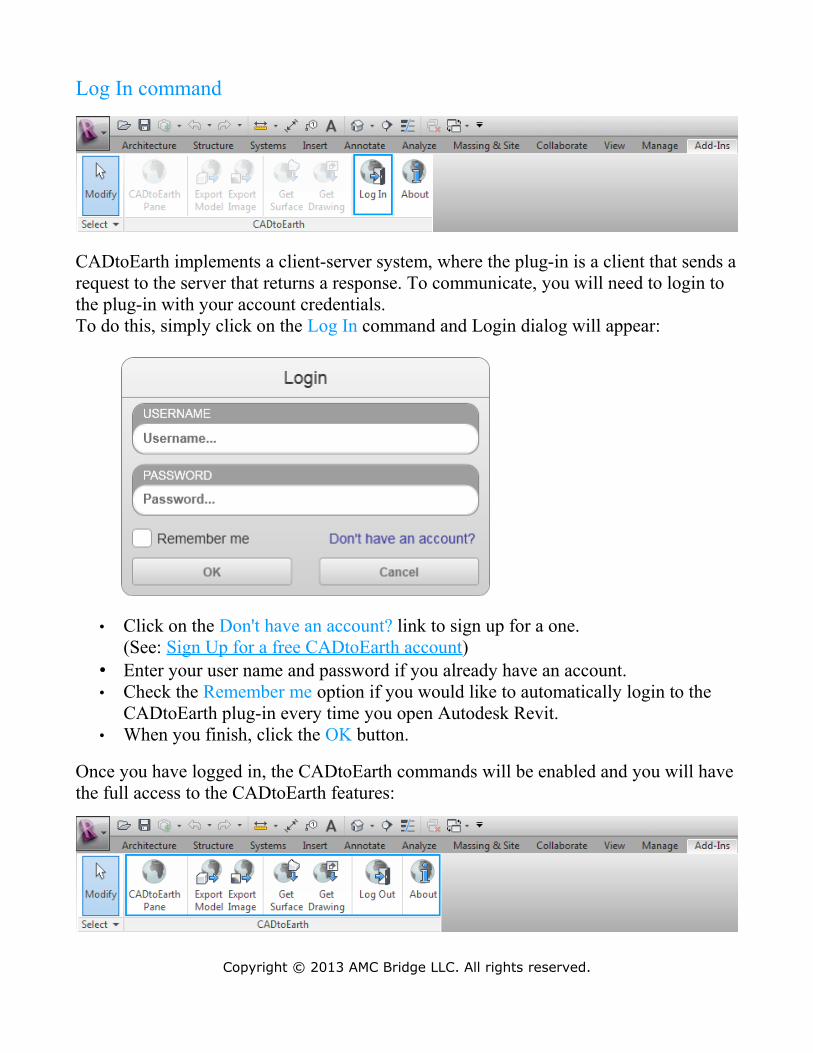
Log In command
CADtoEarth implements a client-server system, where the plug-in is a client that sends a request to the server that returns a response. To communicate, you will need to login to the plug-in with your account credentials.To do this, simply click on the Log In command and Login dialog will appear:
• Click on the Don't have an account? link to sign up for a one.(See: Sign Up for a free CADtoEarth account)
• Enter your user name and password if you already have an account.• Check the Remember me option if you would like to automatically login to the
CADtoEarth plug-in every time you open Autodesk Revit.• When you finish, click the OK button.
Once you have logged in, the CADtoEarth commands will be enabled and you will have the full access to the CADtoEarth features:
Copyright © 2013 AMC Bridge LLC. All rights reserved.
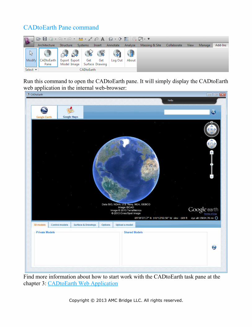
CADtoEarth Pane command
Run this command to open the CADtoEarth pane. It will simply display the CADtoEarth web application in the internal web-browser:
Find more information about how to start work with the CADtoEarth task pane at the chapter 3: CADtoEarth Web Application
Copyright © 2013 AMC Bridge LLC. All rights reserved.
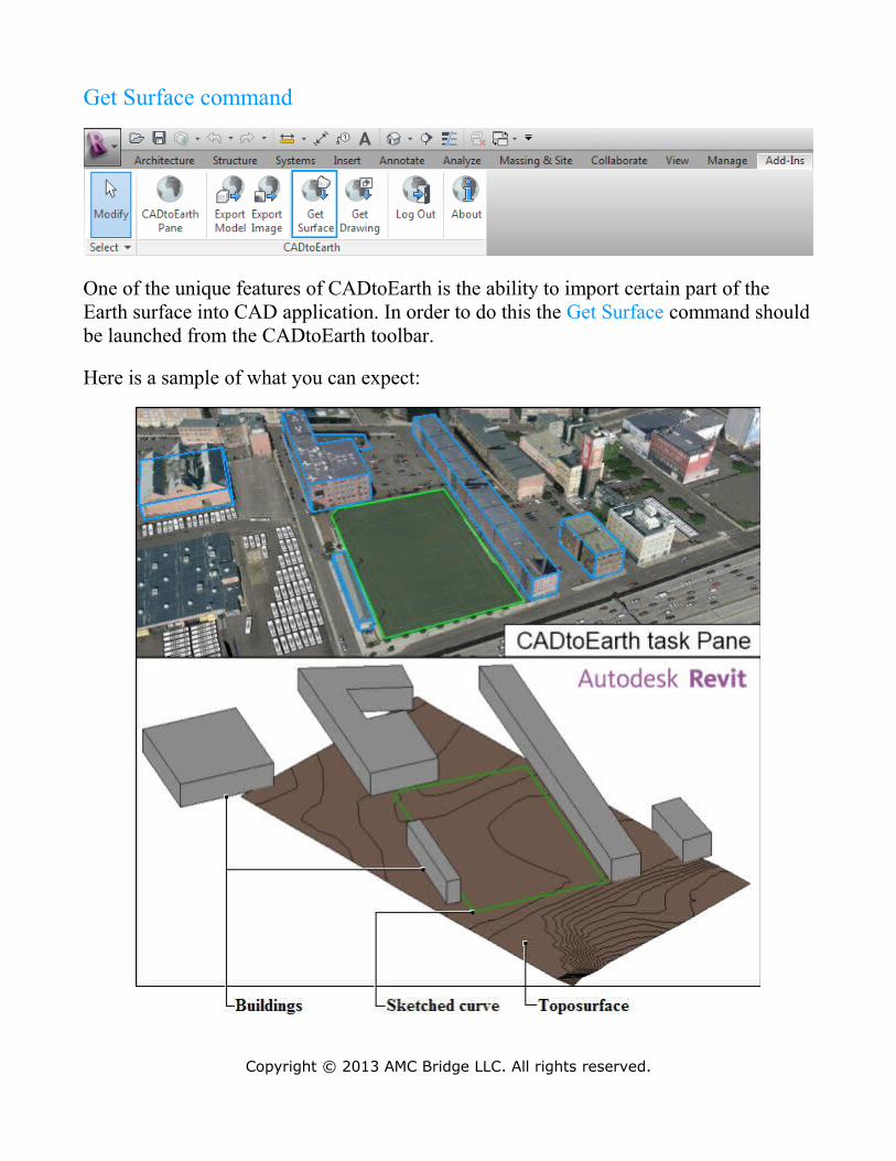
Get Surface command
One of the unique features of CADtoEarth is the ability to import certain part of the Earth surface into CAD application. In order to do this the Get Surface command should be launched from the CADtoEarth toolbar.
Here is a sample of what you can expect:
Copyright © 2013 AMC Bridge LLC. All rights reserved.
Once the command is launched a part of Earth surface captured using the CADtoEarth task pane tools will be imported into the currently opened Revit modeling session as the Toposurface object. (See: How to capture a surface with CADtoEarth task pane)
If some curves were sketched on the Google Earth prior to surface capturing those curves will be brought in along with the surface, which may be useful for example in order to bring the outlines of buildings along with the surfaces they are located on.
Also you can bring in the information about the buildings that are located on the imported part of a surface into the currently opened Revit modeling session as a set of Revit Families.
Information on geographical binding will be imported into the currently opened Revit project also, so if it is published back to Google Earth it will appear at the same geographical location.
Copyright © 2013 AMC Bridge LLC. All rights reserved.
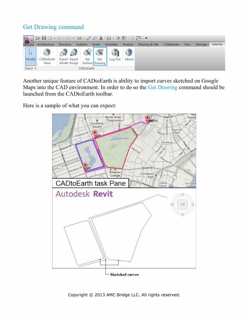
Get Drawing command
Another unique feature of CADtoEarth is ability to import curves sketched on Google Maps into the CAD environment. In order to do so the Get Drawing command should be launched from the CADtoEarth toolbar.
Here is a sample of what you can expect:
Copyright © 2013 AMC Bridge LLC. All rights reserved.
Once the command is launched the curves captured using the CADtoEarth task pane tools will be imported into the currently opened Revit modeling session as a Drawing object. (See: How to create a drawing using CADtoEarth task pane)
The curves will be imported along with the information on geographical binding, so if the model that was built using the imported curves is published back to the Earth it would appear at the same location and would be oriented the same way.
Copyright © 2013 AMC Bridge LLC. All rights reserved.
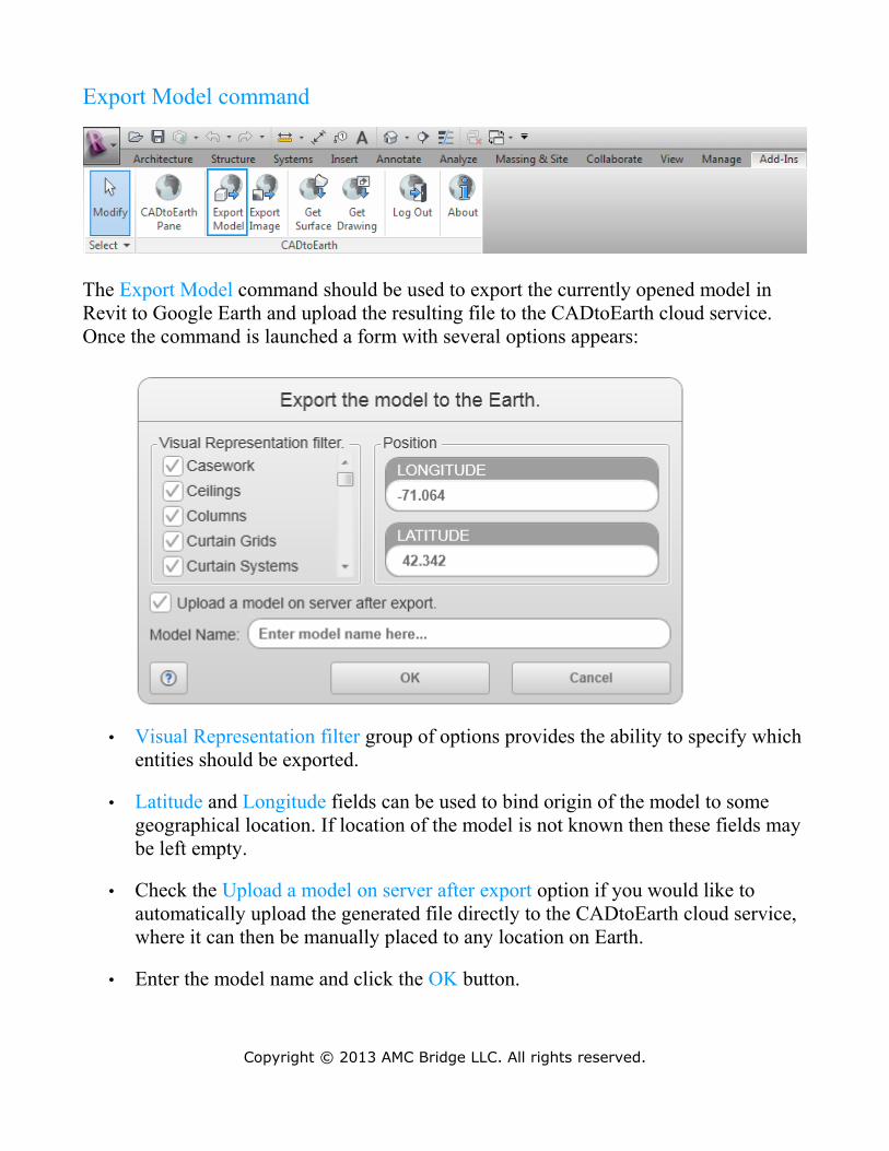
Export Model command
The Export Model command should be used to export the currently opened model in Revit to Google Earth and upload the resulting file to the CADtoEarth cloud service. Once the command is launched a form with several options appears:
• Visual Representation filter group of options provides the ability to specify which entities should be exported.
• Latitude and Longitude fields can be used to bind origin of the model to some geographical location. If location of the model is not known then these fields may be left empty.
• Check the Upload a model on server after export option if you would like to automatically upload the generated file directly to the CADtoEarth cloud service, where it can then be manually placed to any location on Earth.
• Enter the model name and click the OK button.
Copyright © 2013 AMC Bridge LLC. All rights reserved.
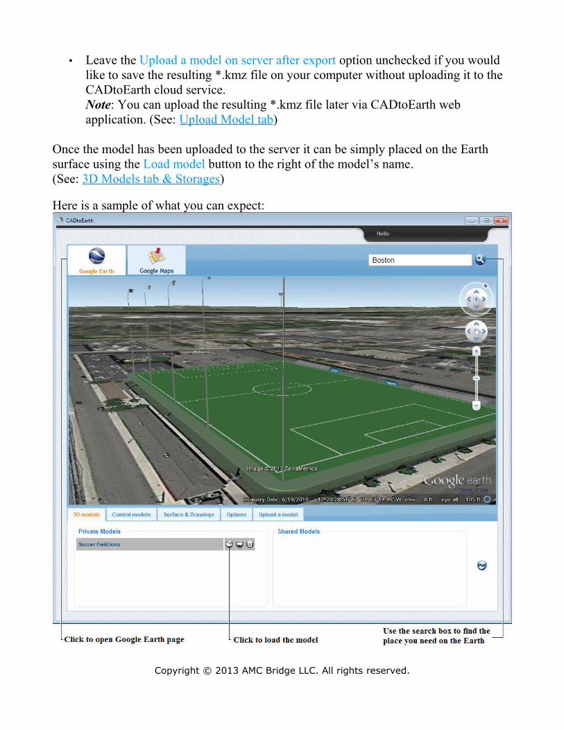
• Leave the Upload a model on server after export option unchecked if you would like to save the resulting *.kmz file on your computer without uploading it to the CADtoEarth cloud service.Note: You can upload the resulting *.kmz file later via CADtoEarth web application. (See: Upload Model tab)
Once the model has been uploaded to the server it can be simply placed on the Earth surface using the Load model button to the right of the model’s name.(See: 3D Models tab & Storages)
Here is a sample of what you can expect:
Copyright © 2013 AMC Bridge LLC. All rights reserved.
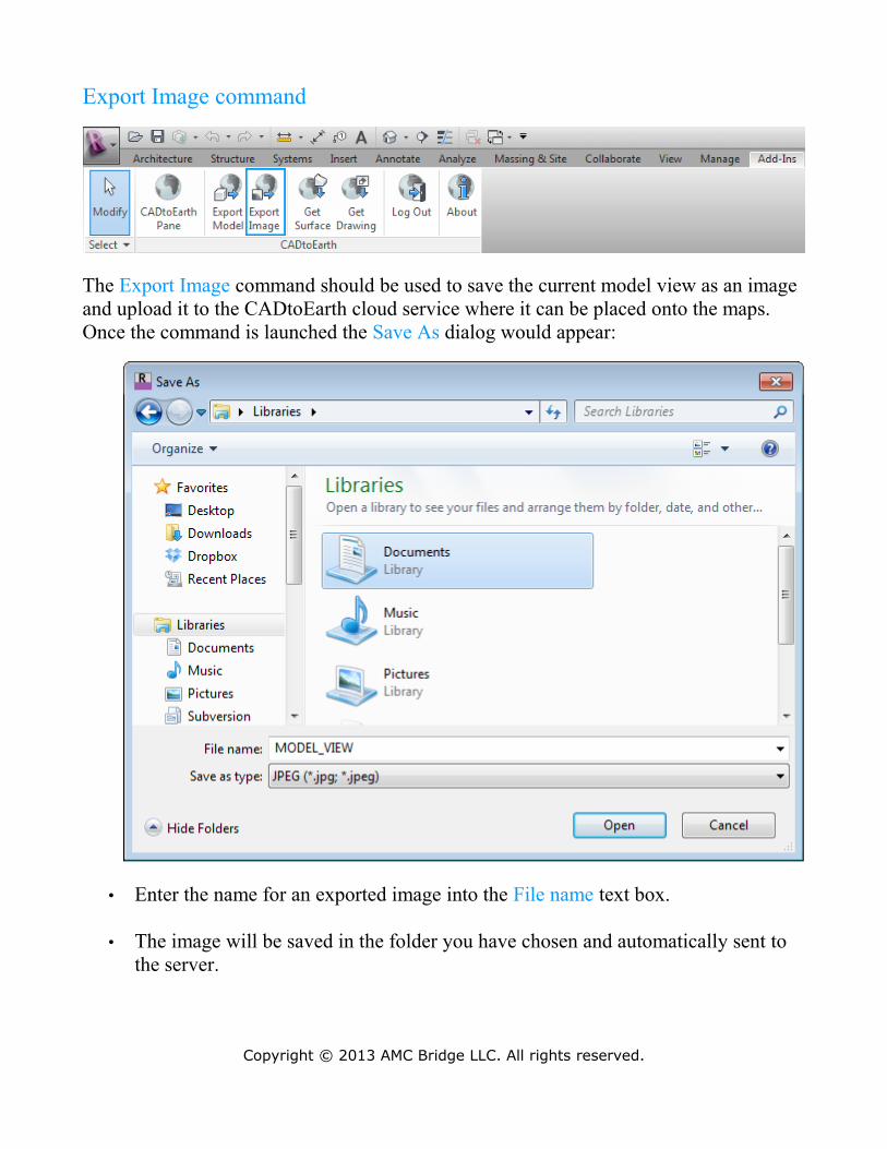
Export Image command
The Export Image command should be used to save the current model view as an image and upload it to the CADtoEarth cloud service where it can be placed onto the maps. Once the command is launched the Save As dialog would appear:
• Enter the name for an exported image into the File name text box.
• The image will be saved in the folder you have chosen and automatically sent to the server.
Copyright © 2013 AMC Bridge LLC. All rights reserved.
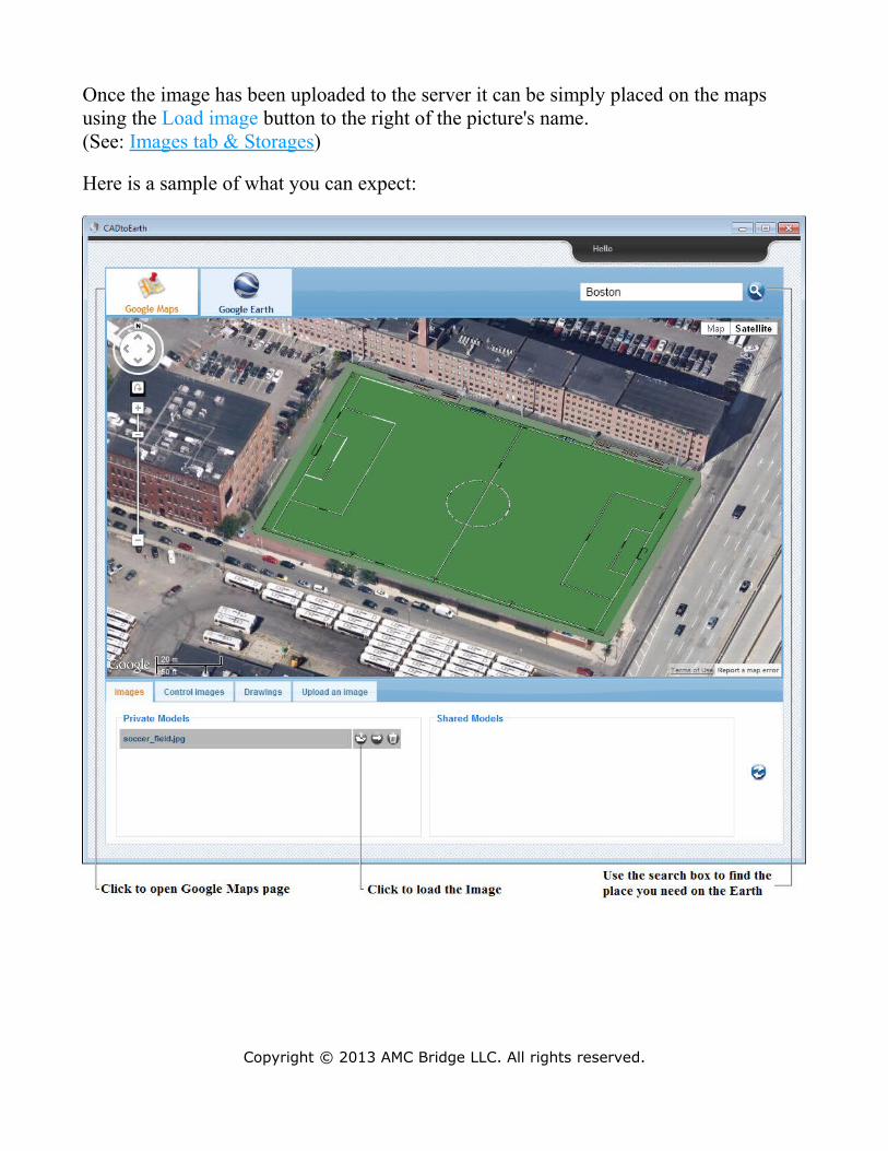
Once the image has been uploaded to the server it can be simply placed on the maps using the Load image button to the right of the picture's name. (See: Images tab & Storages)
Here is a sample of what you can expect:
Copyright © 2013 AMC Bridge LLC. All rights reserved.
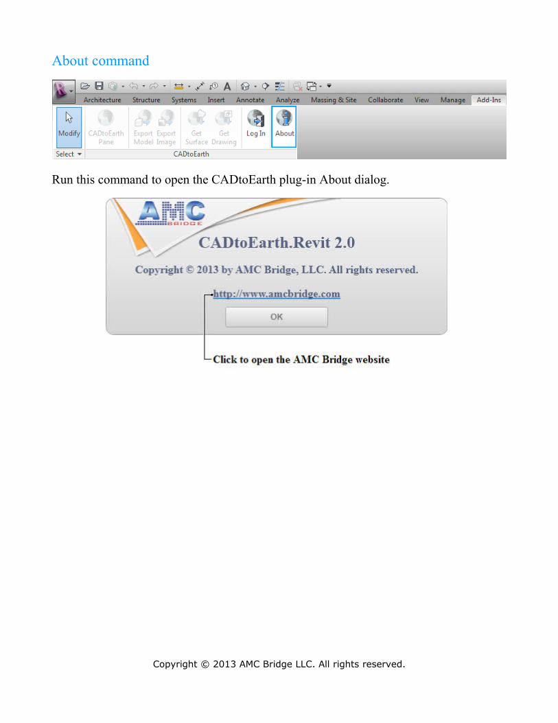
About command
Run this command to open the CADtoEarth plug-in About dialog.
Copyright © 2013 AMC Bridge LLC. All rights reserved.
CADtoEarth Web Application
Introduction
The CADtoEarth web application exposes some exciting capabilities, including the abilities to:
• Capturing of the certain part of Earth surface from the Google Earth.• Sketching in Google Earth and Google Maps environments.• Provides a personal storage for every CADtoEarth account, where the 3D models
and Images will be placed.• Provides a set of tools that will help you manage your 3D models. You can move,
rotate and scale your 3D structures in order to fit the surrounding area.• Share your 3D models with other CADtoEarth users.• Choose the models to be placed at startup. It can be useful when you work with a
set of 3D models.
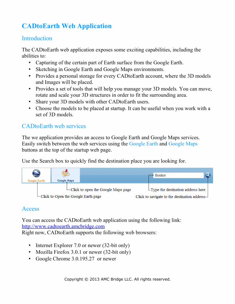
CADtoEarth web services
The we application provides an access to Google Earth and Google Maps services. Easily switch between the web services using the Google Earth and Google Maps buttons at the top of the startup web page.
Use the Search box to quickly find the destination place you are looking for.
Access
You can access the CADtoEarth web application using the following link: http://www.cadtoearth.amcbridge.comRight now, CADtoEarth supports the following web browsers:
• Internet Explorer 7.0 or newer (32-bit only)• Mozilla Firefox 3.0.1 or newer (32-bit only)• Google Chrome 3.0.195.27 or newer
Copyright © 2013 AMC Bridge LLC. All rights reserved.
Google Earth Tools
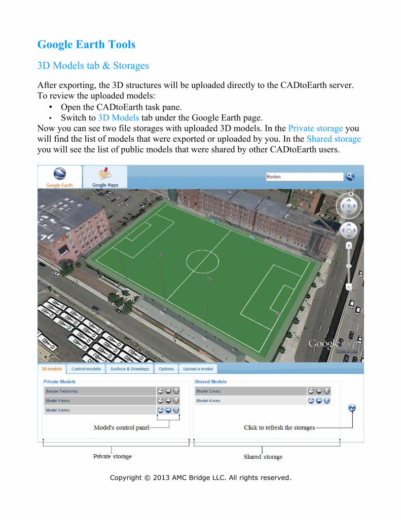
3D Models tab & Storages
After exporting, the 3D structures will be uploaded directly to the CADtoEarth server. To review the uploaded models:
• Open the CADtoEarth task pane.• Switch to 3D Models tab under the Google Earth page.
Now you can see two file storages with uploaded 3D models. In the Private storage you will find the list of models that were exported or uploaded by you. In the Shared storage you will see the list of public models that were shared by other CADtoEarth users.
Copyright © 2013 AMC Bridge LLC. All rights reserved.
Note: By default the models exported from the CAD environment will be stored to the Private storage.
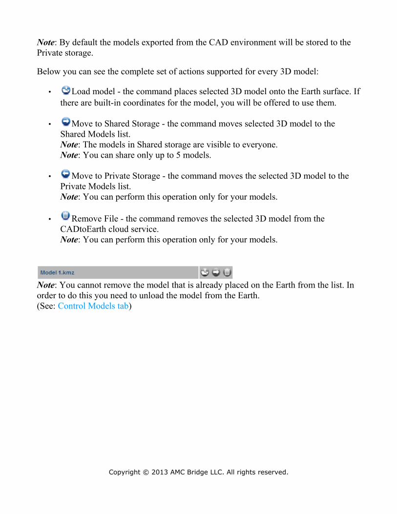
Below you can see the complete set of actions supported for every 3D model:
• Load model - the command places selected 3D model onto the Earth surface. If there are built-in coordinates for the model, you will be offered to use them.
• Move to Shared Storage - the command moves selected 3D model to the Shared Models list.Note: The models in Shared storage are visible to everyone.Note: You can share only up to 5 models.
• Move to Private Storage - the command moves the selected 3D model to the Private Models list.Note: You can perform this operation only for your models.
• Remove File - the command removes the selected 3D model from the CADtoEarth cloud service.Note: You can perform this operation only for your models.
Note: You cannot remove the model that is already placed on the Earth from the list. In order to do this you need to unload the model from the Earth.(See: Control Models tab)
Copyright © 2013 AMC Bridge LLC. All rights reserved.
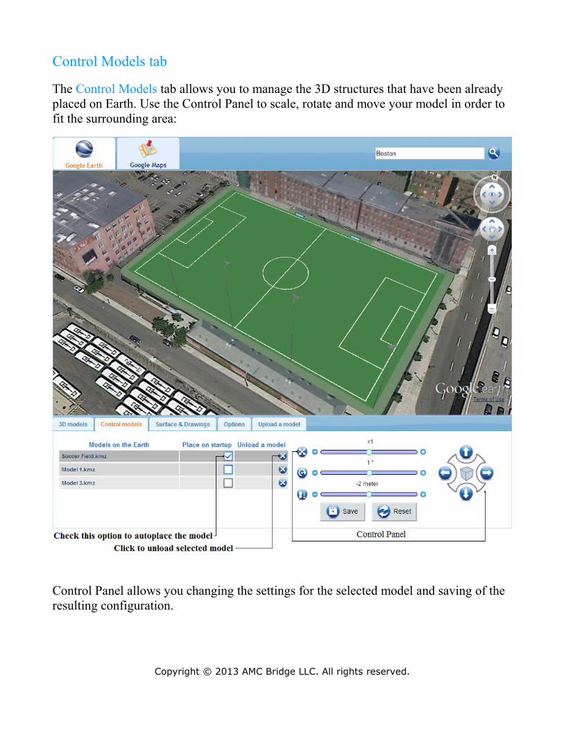
Control Models tab
The Control Models tab allows you to manage the 3D structures that have been already placed on Earth. Use the Control Panel to scale, rotate and move your model in order to fit the surrounding area:
Control Panel allows you changing the settings for the selected model and saving of the resulting configuration.
Copyright © 2013 AMC Bridge LLC. All rights reserved.
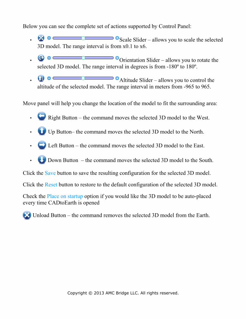
Below you can see the complete set of actions supported by Control Panel:
• Scale Slider – allows you to scale the selected 3D model. The range interval is from x0.1 to x6.
• Orientation Slider – allows you to rotate the selected 3D model. The range interval in degrees is from -180º to 180º.
• Altitude Slider – allows you to control the altitude of the selected model. The range interval in meters from -965 to 965.
Move panel will help you change the location of the model to fit the surrounding area:
• Right Button – the command moves the selected 3D model to the West.
• Up Button– the command moves the selected 3D model to the North.
• Left Button – the command moves the selected 3D model to the East.
• Down Button – the command moves the selected 3D model to the South.
Click the Save button to save the resulting configuration for the selected 3D model.
Click the Reset button to restore to the default configuration of the selected 3D model.
Check the Place on startup option if you would like the 3D model to be auto-placed every time CADtoEarth is opened
Unload Button – the command removes the selected 3D model from the Earth.
Copyright © 2013 AMC Bridge LLC. All rights reserved.
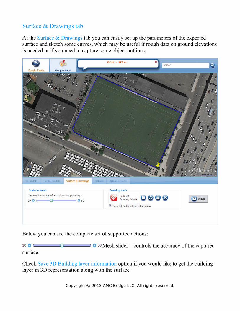
Surface & Drawings tab
At the Surface & Drawings tab you can easily set up the parameters of the exported surface and sketch some curves, which may be useful if rough data on ground elevations is needed or if you need to capture some object outlines:
Below you can see the complete set of supported actions:
Mesh slider – controls the accuracy of the captured surface.
Check Save 3D Building layer information option if you would like to get the building layer in 3D representation along with the surface.
Copyright © 2013 AMC Bridge LLC. All rights reserved.
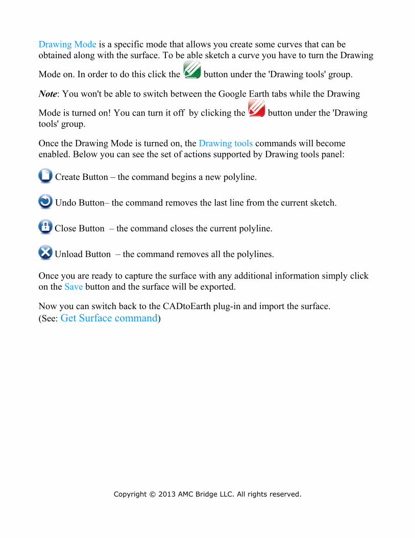
Drawing Mode is a specific mode that allows you create some curves that can be obtained along with the surface. To be able sketch a curve you have to turn the Drawing
Mode on. In order to do this click the button under the 'Drawing tools' group.
Note: You won't be able to switch between the Google Earth tabs while the Drawing
Mode is turned on! You can turn it off by clicking the button under the 'Drawing tools' group.
Once the Drawing Mode is turned on, the Drawing tools commands will become enabled. Below you can see the set of actions supported by Drawing tools panel:
Create Button – the command begins a new polyline.
Undo Button– the command removes the last line from the current sketch.
Close Button – the command closes the current polyline.
Unload Button – the command removes all the polylines.
Once you are ready to capture the surface with any additional information simply click on the Save button and the surface will be exported.
Now you can switch back to the CADtoEarth plug-in and import the surface.(See: Get Surface command)
Copyright © 2013 AMC Bridge LLC. All rights reserved.
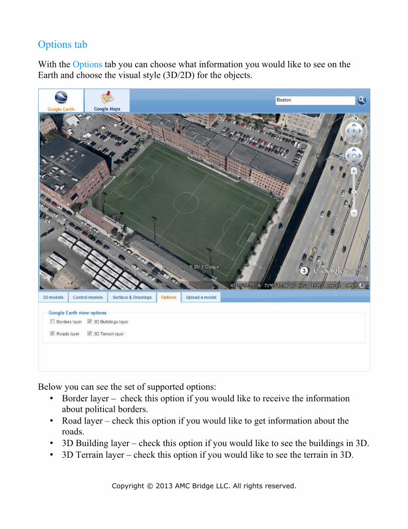
Options tab
With the Options tab you can choose what information you would like to see on the Earth and choose the visual style (3D/2D) for the objects.
Below you can see the set of supported options:• Border layer – check this option if you would like to receive the information
about political borders.• Road layer – check this option if you would like to get information about the
roads.• 3D Building layer – check this option if you would like to see the buildings in 3D.• 3D Terrain layer – check this option if you would like to see the terrain in 3D.
Copyright © 2013 AMC Bridge LLC. All rights reserved.
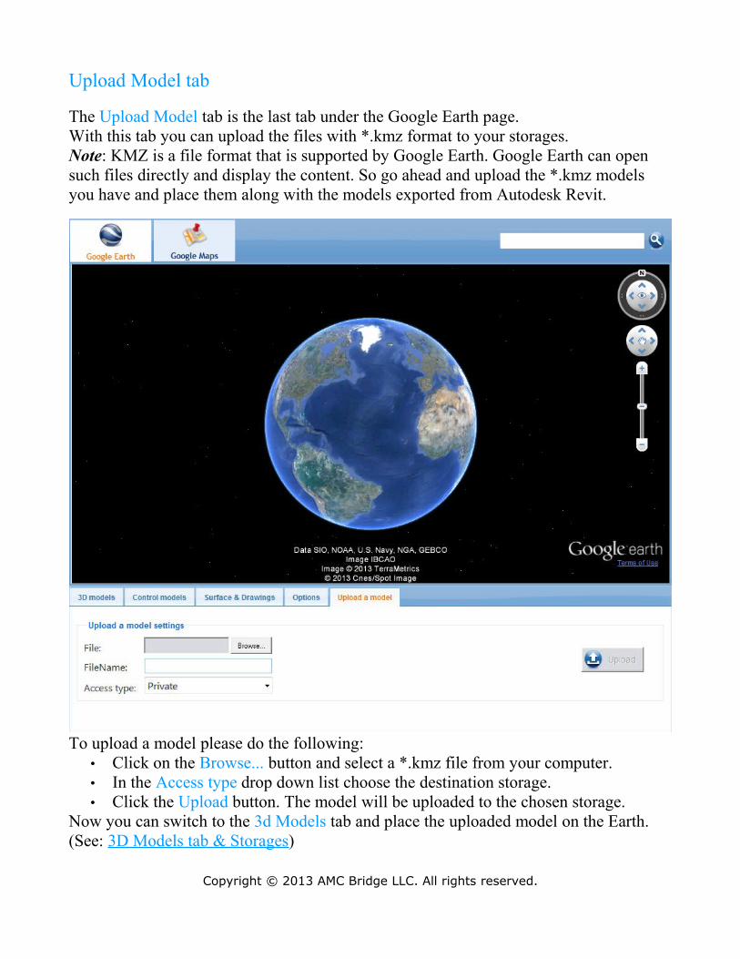
Upload Model tab
The Upload Model tab is the last tab under the Google Earth page.With this tab you can upload the files with *.kmz format to your storages.Note: KMZ is a file format that is supported by Google Earth. Google Earth can open such files directly and display the content. So go ahead and upload the *.kmz models you have and place them along with the models exported from Autodesk Revit.
To upload a model please do the following:• Click on the Browse... button and select a *.kmz file from your computer.• In the Access type drop down list choose the destination storage.• Click the Upload button. The model will be uploaded to the chosen storage.
Now you can switch to the 3d Models tab and place the uploaded model on the Earth.(See: 3D Models tab & Storages)
Copyright © 2013 AMC Bridge LLC. All rights reserved.
Google Maps Tools
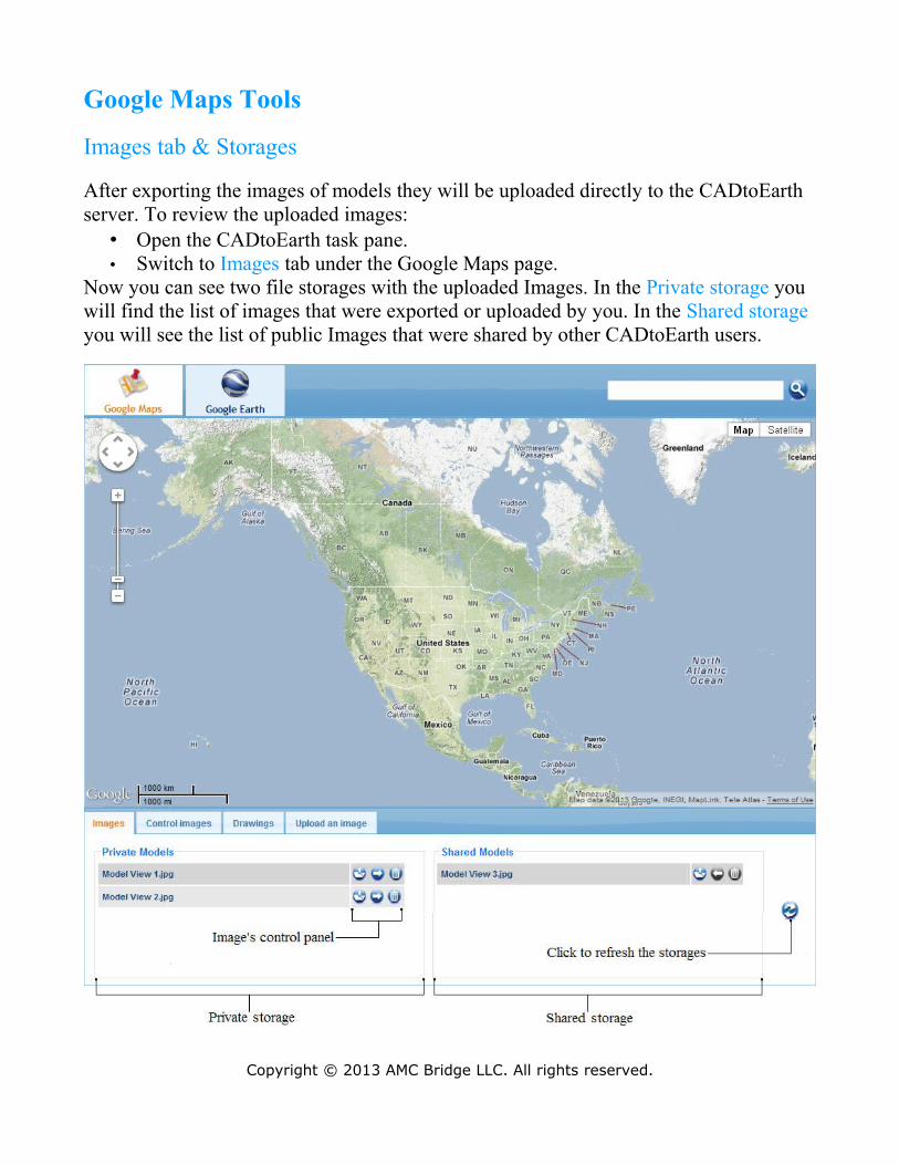
Images tab & Storages
After exporting the images of models they will be uploaded directly to the CADtoEarth server. To review the uploaded images:
• Open the CADtoEarth task pane.• Switch to Images tab under the Google Maps page.
Now you can see two file storages with the uploaded Images. In the Private storage you will find the list of images that were exported or uploaded by you. In the Shared storage you will see the list of public Images that were shared by other CADtoEarth users.
Copyright © 2013 AMC Bridge LLC. All rights reserved.
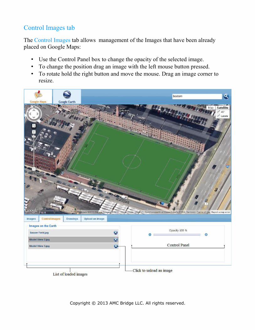
Control Images tab
The Control Images tab allows management of the Images that have been already placed on Google Maps:
• Use the Control Panel box to change the opacity of the selected image.• To change the position drag an image with the left mouse button pressed.• To rotate hold the right button and move the mouse. Drag an image corner to
resize.
Copyright © 2013 AMC Bridge LLC. All rights reserved.

Drawings tab
At the Drawings tab you can easily sketch some curves, which may be useful if you need to capture some object outlines:
Drawing Mode is a specific mode that allows you to create some curves that can be exported from Google Maps. To be able to sketch a curve you have to turn the Drawing
Mode on. In order to do this click the button under the 'Drawing tools' group.
Note: You won't be able to switch between the Google Maps tabs while the Drawing
Copyright © 2013 AMC Bridge LLC. All rights reserved.
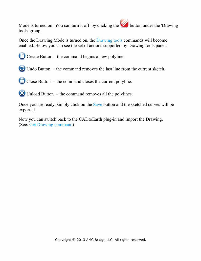
Mode is turned on! You can turn it off by clicking the button under the 'Drawing tools' group.
Once the Drawing Mode is turned on, the Drawing tools commands will become enabled. Below you can see the set of actions supported by Drawing tools panel:
Create Button – the command begins a new polyline.
Undo Button – the command removes the last line from the current sketch.
Close Button – the command closes the current polyline.
Unload Button – the command removes all the polylines.
Once you are ready, simply click on the Save button and the sketched curves will be exported.
Now you can switch back to the CADtoEarth plug-in and import the Drawing.(See: Get Drawing command)
Copyright © 2013 AMC Bridge LLC. All rights reserved.
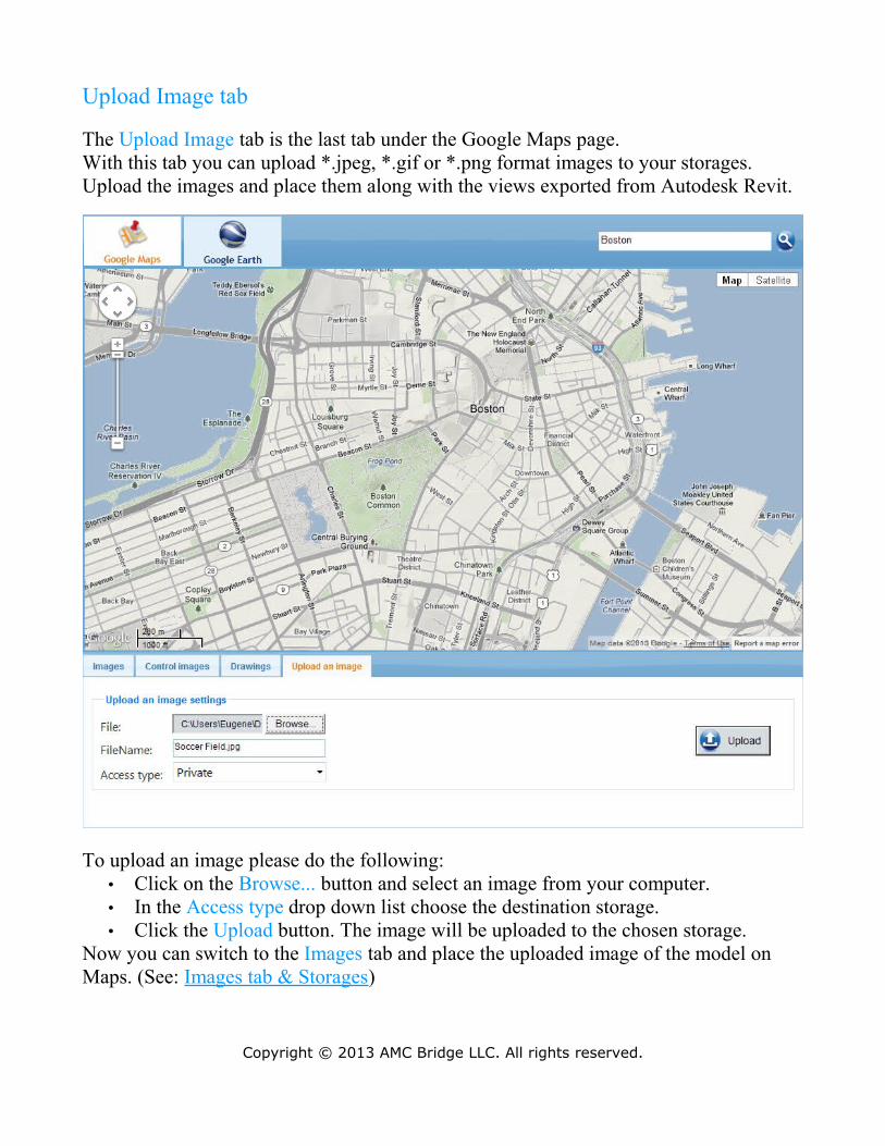
Upload Image tab
The Upload Image tab is the last tab under the Google Maps page.With this tab you can upload *.jpeg, *.gif or *.png format images to your storages.Upload the images and place them along with the views exported from Autodesk Revit.
To upload an image please do the following:• Click on the Browse... button and select an image from your computer.• In the Access type drop down list choose the destination storage.• Click the Upload button. The image will be uploaded to the chosen storage.
Now you can switch to the Images tab and place the uploaded image of the model on Maps. (See: Images tab & Storages)
Copyright © 2013 AMC Bridge LLC. All rights reserved.
Appendix A: Contact Us
AMC Bridge has a global footprint with offices and development centers in North America and Ukraine. Our North American headquarters in New Jersey handles all Sales, Administrative and Business inquiries. Most of our software developers are located in our state of the art office in Dnepropetrovsk, Ukraine.
Please let us know how we can help you, and we will get in touch with you as soon as we can.
AMC Bridge North America Headquarters:
10 Lake Shore Drive S.Randolph, NJ 07869
Phone: +1 973-895-1724Fax: +1 973-895-5376
For all online inquiries, please contact: [email protected] Support: [email protected]
You can contact us right now.
We look forward to hearing from you.
Copyright © 2013 AMC Bridge LLC. All rights reserved.