Embed Size (px)
Citation preview
5V MACHINE
OWNERS MANUAL
ROLL FORMER CORP. 140 INDEPENDENCE LANE • CHALFONT, PA 18914
215-997-2511 • FAX: 215-997-5544
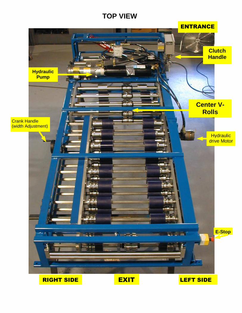
TOP VIEW
Center V-Rolls
(175$1&(�
5,*+7�6,'(�
Clutch Handle
Hydraulic Pump
/()7�6,'(�(;,7�
Crank Handle (width Adjustment)
Hydraulic drive Motor
E-Stop
23(5$7,1*�,16758&7,216�
�52//�)250(5�3$1)250(5�02'(/��9�
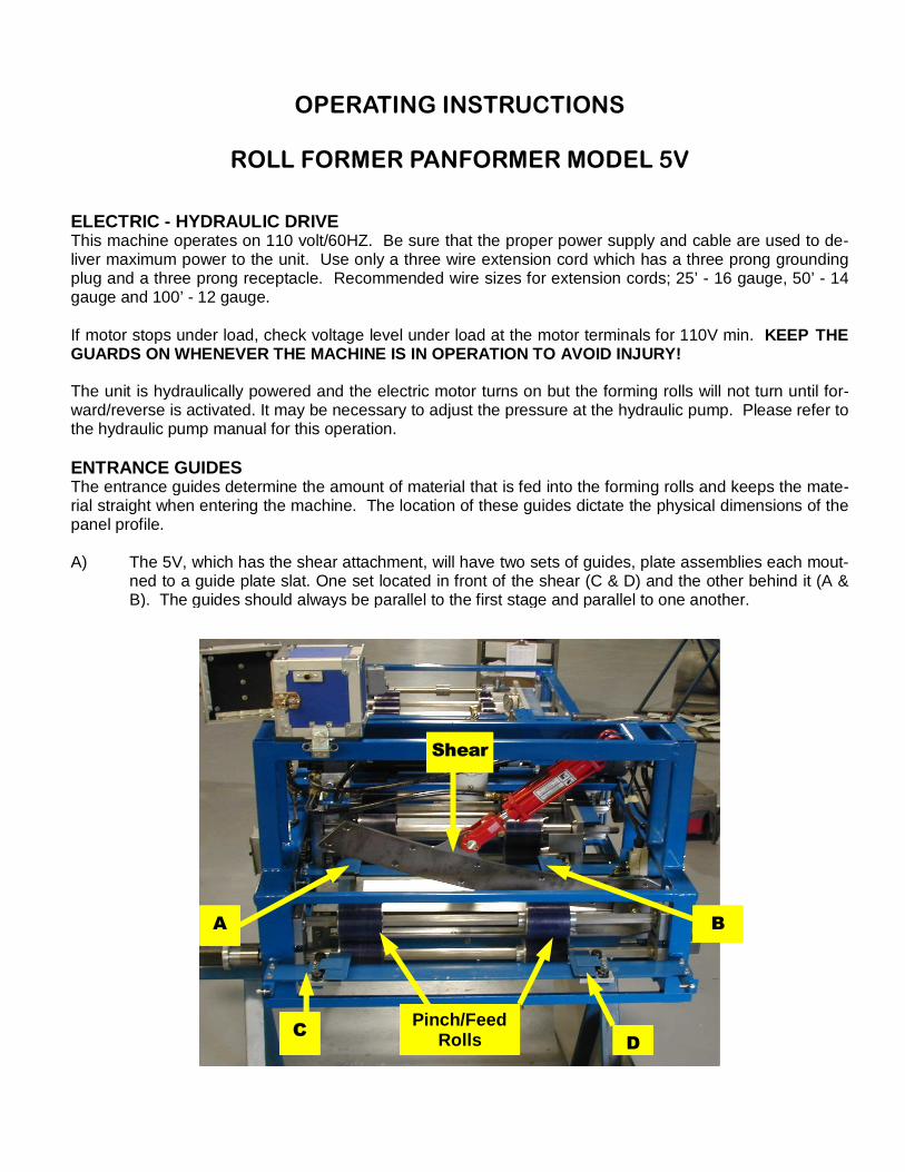
ELECTRIC - HYDRAULIC DRIVE This machine operates on 110 volt/60HZ. Be sure that the proper power supply and cable are used to de-liver maximum power to the unit. Use only a three wire extension cord which has a three prong grounding plug and a three prong receptacle. Recommended wire sizes for extension cords; 25’ - 16 gauge, 50’ - 14 gauge and 100’ - 12 gauge. If motor stops under load, check voltage level under load at the motor terminals for 110V min. KEEP THE GUARDS ON WHENEVER THE MACHINE IS IN OPERATION TO AVOID INJURY! The unit is hydraulically powered and the electric motor turns on but the forming rolls will not turn until for-ward/reverse is activated. It may be necessary to adjust the pressure at the hydraulic pump. Please refer to the hydraulic pump manual for this operation. ENTRANCE GUIDES The entrance guides determine the amount of material that is fed into the forming rolls and keeps the mate-rial straight when entering the machine. The location of these guides dictate the physical dimensions of the panel profile. A) The 5V, which has the shear attachment, will have two sets of guides, plate assemblies each mout-
ned to a guide plate slat. One set located in front of the shear (C & D) and the other behind it (A & B). The guides should always be parallel to the first stage and parallel to one another.
66KKHDHDUU��
%�$�
Pinch/Feed Rolls &&��
'�
THE MOST IMPORTANT FACTOR IN THE OPERATION OF THE MACHINE IS THAT THE MATERIAL ENTER THE MACHINE STRAIGHT. When using a coil, the decoiler should be located with the left side of the material being exactly in line with the left side guides. If possible, try to have at least 6’-8’ of distance from Decoiler to the front entrance guides of the machine.
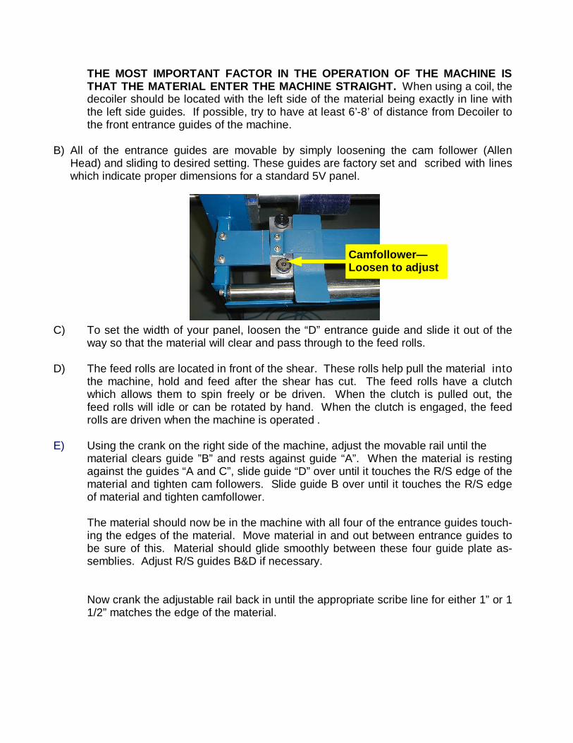
B) All of the entrance guides are movable by simply loosening the cam follower (Allen
Head) and sliding to desired setting. These guides are factory set and scribed with lines which indicate proper dimensions for a standard 5V panel.
C) To set the width of your panel, loosen the “D” entrance guide and slide it out of the way so that the material will clear and pass through to the feed rolls. D) The feed rolls are located in front of the shear. These rolls help pull the material into the machine, hold and feed after the shear has cut. The feed rolls have a clutch which allows them to spin freely or be driven. When the clutch is pulled out, the feed rolls will idle or can be rotated by hand. When the clutch is engaged, the feed rolls are driven when the machine is operated . E) Using the crank on the right side of the machine, adjust the movable rail until the
material clears guide ”B” and rests against guide “A”. When the material is resting against the guides “A and C”, slide guide “D” over until it touches the R/S edge of the material and tighten cam followers. Slide guide B over until it touches the R/S edge of material and tighten camfollower. The material should now be in the machine with all four of the entrance guides touch-ing the edges of the material. Move material in and out between entrance guides to be sure of this. Material should glide smoothly between these four guide plate as-semblies. Adjust R/S guides B&D if necessary.
Now crank the adjustable rail back in until the appropriate scribe line for either 1” or 1 1/2” matches the edge of the material.
Camfollower— Loosen to adjust
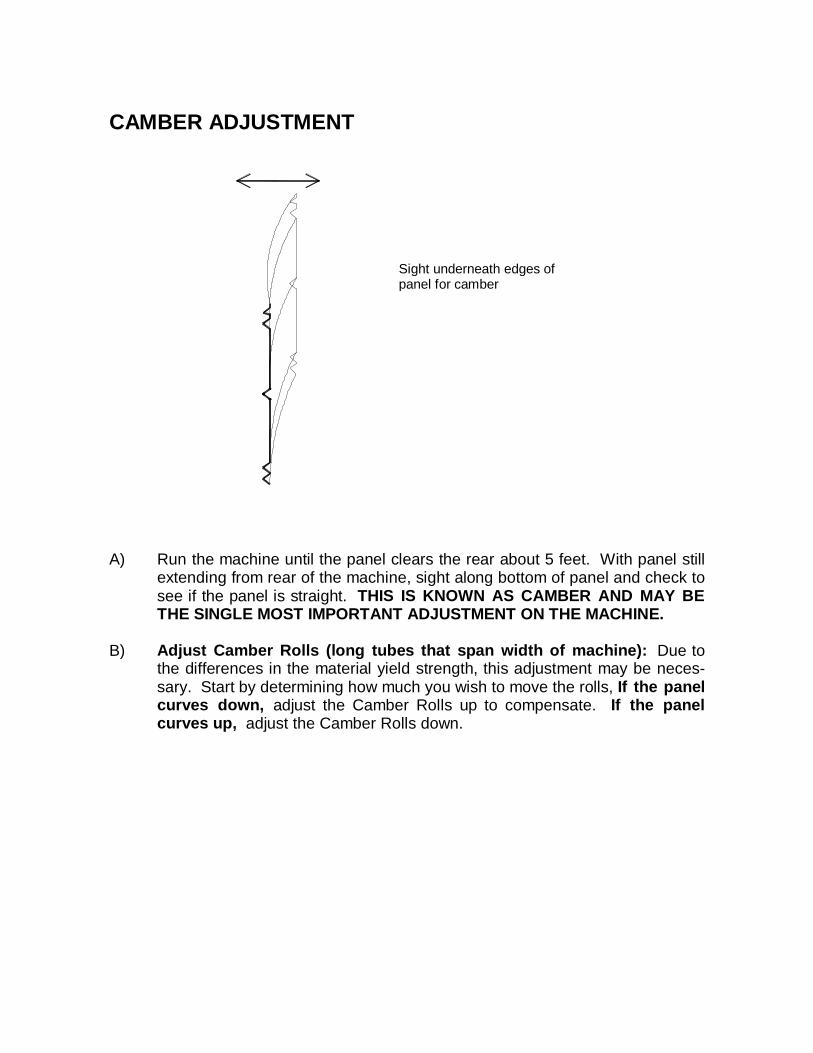
CAMBER ADJUSTMENT A) Run the machine until the panel clears the rear about 5 feet. With panel still
extending from rear of the machine, sight along bottom of panel and check to see if the panel is straight. THIS IS KNOWN AS CAMBER AND MAY BE THE SINGLE MOST IMPORTANT ADJUSTMENT ON THE MACHINE.
B) Adjust Camber Rolls (long tubes that span width of machine): Due to
the differences in the material yield strength, this adjustment may be neces-sary. Start by determining how much you wish to move the rolls, If the panel curves down, adjust the Camber Rolls up to compensate. If the panel curves up, adjust the Camber Rolls down.
Sight underneath edges of panel for camber
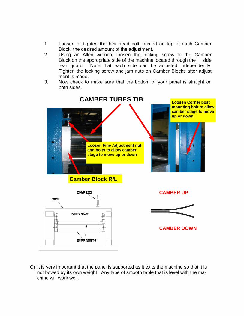
1. Loosen or tighten the hex head bolt located on top of each Camber
Block, the desired amount of the adjustment. 2. Using an Allen wrench, loosen the locking screw to the Camber
Block on the appropriate side of the machine located through the side rear guard. Note that each side can be adjusted independently. Tighten the locking screw and jam nuts on Camber Blocks after adjust ment is made.
3. Now check to make sure that the bottom of your panel is straight on both sides.
CAMBER TUBES T/B
C) It is very important that the panel is supported as it exits the machine so that it is
not bowed by its own weight. Any type of smooth table that is level with the ma-chine will work well.
Loosen Fine Adjustment nut and b olts to allow camber stage to move up or down
Camber Block R/L
Loosen Corner post mounting bolt to allow camber stage to move up or down
CAMBER UP
CAMBER DOWN
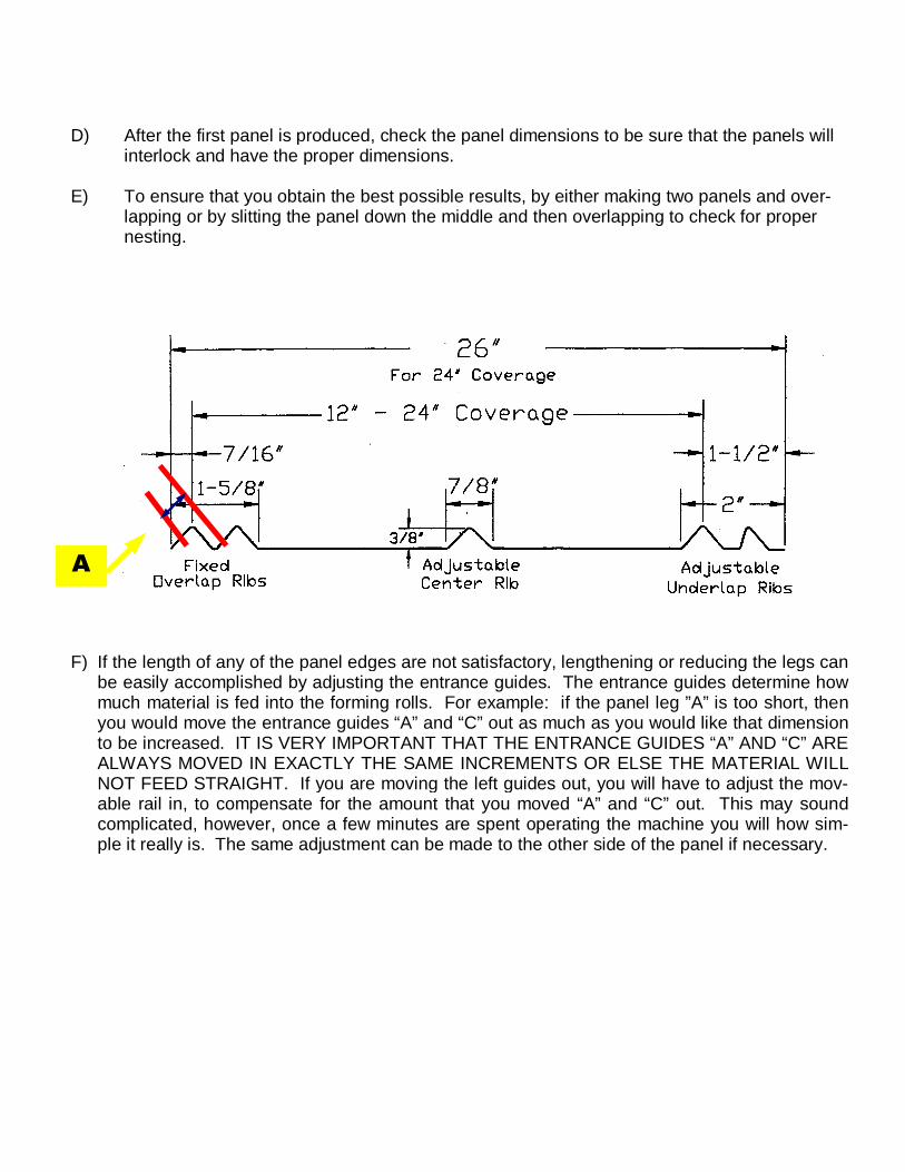
D) After the first panel is produced, check the panel dimensions to be sure that the panels will
interlock and have the proper dimensions. E) To ensure that you obtain the best possible results, by either making two panels and over-
lapping or by slitting the panel down the middle and then overlapping to check for proper nesting.
F) If the length of any of the panel edges are not satisfactory, lengthening or reducing the legs can
be easily accomplished by adjusting the entrance guides. The entrance guides determine how much material is fed into the forming rolls. For example: if the panel leg ”A” is too short, then you would move the entrance guides “A” and “C” out as much as you would like that dimension to be increased. IT IS VERY IMPORTANT THAT THE ENTRANCE GUIDES “A” AND “C” ARE ALWAYS MOVED IN EXACTLY THE SAME INCREMENTS OR ELSE THE MATERIAL WILL NOT FEED STRAIGHT. If you are moving the left guides out, you will have to adjust the mov-able rail in, to compensate for the amount that you moved “A” and “C” out. This may sound complicated, however, once a few minutes are spent operating the machine you will how sim-ple it really is. The same adjustment can be made to the other side of the panel if necessary.
$�
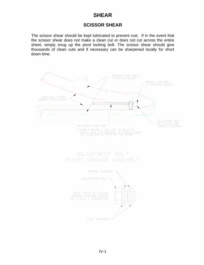
SHEAR
SCISSOR SHEAR The scissor shear should be kept lubricated to prevent rust. If in the event that the scissor shear does not make a clean cut or does not cut across the entire sheet, simply snug up the pivot locking bolt. The scissor shear should give thousands of clean cuts and if necessary can be sharpened locally for short down time.
IV-1
SHEAR A) The shear should be kept lubricated to prevent rust. If in the event that the shear
does not make a clean cut or does not cut across the entire sheet, simply tighten the pivot locking bolt. The shear should give thousands of clean cuts and if nec-essary can be sharpened locally for short down time.
Hexagonal shafts must be kept clean. DO NOT use OIL OR GREASE on these shafts. This will attract dust and grit which will stick and cause wear. Simply wipe the shafts clean and apply a SILICONE SPRAY LUBRICANT. Galvanized steel and some other coated sheet may leave a deposit on the stainless steel forming rolls. If this is a problem, it may be prevented by applying a light coating of “GALV-OFF” (a product of the Lock former Corp.) on the STEEL PORTION OF THE FORMING ROLLS ONLY. should a deposit build up it can be removed using a fine abrasive cloth, such as “SCOTCHBRITE” made by the 3M Company. To clean the RUBBER ROLLS use a DEGREASING SOLVENT and a clean cloth. Do not attempt to clean rolls while the machine is plugged in. The material chosen to roll form is very important to the quality of the finished panel. It is very important that your material has a constant width, if it is not even, you will get uneven edges on your panels. It is normal to get a small amount of edge flair at the beginning and end of the panel. The installation of your panels is the most important aspect of your job. The underlay-ment and overall flatness of the roof deck will be the greatest factor in determining the overall flatness of the metal roof. If your edges gradually gain or lose material over the length of the sheet, your entrance guides may not be set parallel to the forming rolls. What you lose on one edge, you will gain on the other. To compensate, move the left rear guide “C” toward the side that loses the material, about .050. Adjust the guide back over the edge of the material. Run another panel and check the legs again. More or less adjustment may be needed.
5V Specifications Forming Stages - 14 Width - adjustable 14”- 28” Panels Fully Automatic Operation-Optional Power - 3HP Electric-Hydraulic Shear - precut/scissors Speed - 40 fpm Length - 12 ft Weight - 2,000 lbs
Materials: Steel - 28ga to 24ga, Aluminum - .024 to .032, Copper - 16oz max

When transporting the machine, transport with a piece of material in the machine and put the shear in the down position. Keep machine out of rain and dampness if possible. Lubricate any area of the machine that shows any signs of rust.
VERY IMPORTANT Disconn ect all power before removing any covers on the machine. Disconn ect all power before servicing and adjusting the machinery. Do no t operate the machine at any time with the covers removed.
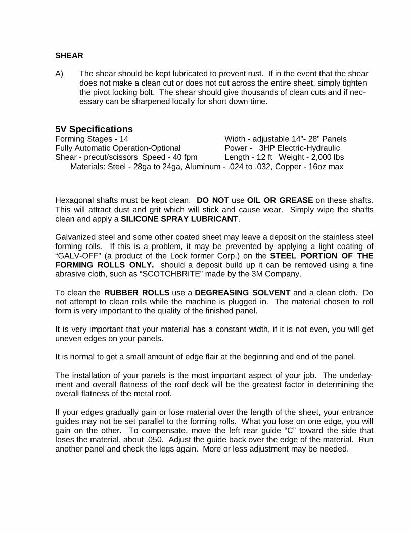
SETTING CENTER RIB ON 5V MACHINE 1) Using a tape measure, measure the distance between the inside of the left rail and
the center of BL1 roll (top of the rib). * See photo #1 for 24” flat stock this dimen-sion will be approximately 12½”.
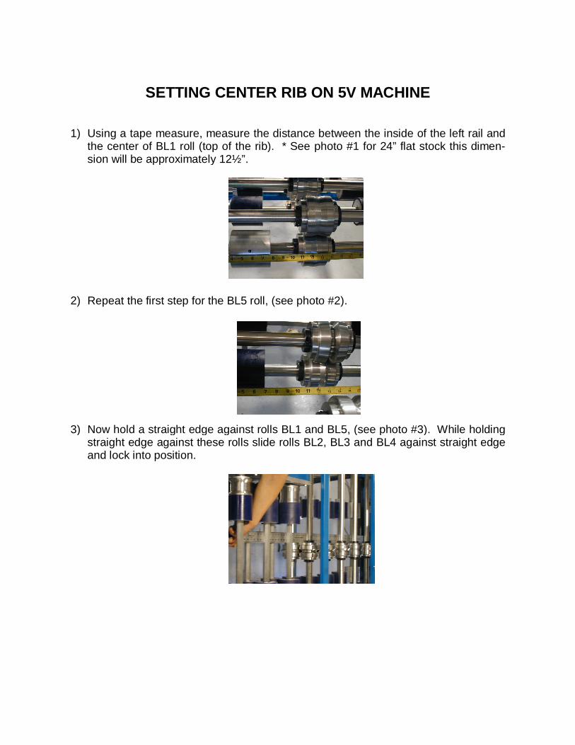
2) Repeat the first step for the BL5 roll, (see photo #2). 3) Now hold a straight edge against rolls BL1 and BL5, (see photo #3). While holding
straight edge against these rolls slide rolls BL2, BL3 and BL4 against straight edge and lock into position.
4) Sight between TL1 roll and B1 roll from front of machine (see photo #4). Slide roll TL1 left or right till there is an even gapping between rolls and lock into position.
5) Looking in from exit of machine repeat step four for rolls TL5 and BL5. 6) After setting TL1 and TL5, use the straight edge to set TL2, TL3 and TL4 as you did
in step #3. NOTE: (using a mirror may help in aligning rolls, however be careful to hold square to rolls for a true image)
7) After locking the first five stages of rib rolls adjust aluminum and rubber rolls to sup-
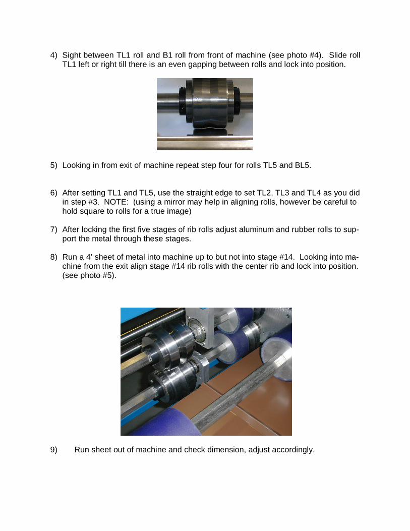
port the metal through these stages. 8) Run a 4’ sheet of metal into machine up to but not into stage #14. Looking into ma-
chine from the exit align stage #14 rib rolls with the center rib and lock into position. (see photo #5).
9) Run sheet out of machine and check dimension, adjust accordingly.

STANDARD EQUIPMENT WARRANTY �4QNN�(QTOGT�%QTRQTCVKQP�YCTTCPVU�VQ�VJG�QTKIKPCN�RWTEJCUGT�VJCV�VJG�GSWKROGPV�KU�HTGG�HTQO�FGHGEVU�K P�OCVGTKCN�CPF�YQTMOCPUJKR�KP�PQTOCN�WUG�CPF�UGTXKEG���0QTOCN�WUG�CPF�UGTXKEG�FQGU�PQV�GZVGPF�VQ�F G�HGEVU�HTQO�OKUJCPFNKPI��VCORGTKPI�QT�OQFKH[KPI�VJG�GSWKROGPV���6JG�VGTO�QH� VJKU�YCTTCPV[� KU� HQT�C�RGTKQF�QH� PKPGV[�����FC[U� HQT� VJG�5GCOGT�CPF�QPG�JWPFTGF�CPF�GKIJV[������FC[U�HQT�CNN�QVJGT�4QNN�(QTOKPI�'SWKROGPV�HTQO�VJG�FCVG�QH�VJG�TGEGKRV�QH�VJG�GSWKROGPV�VQ�VJG�QTKIKPCN�RWTEJCUGT���4QNN�(QTOGT�%QTRQTCVKQP�UJCNN�TGRCKT�QT�TGRNCEG�VJG�FGHGEVKXG�RCTVU�CV�VJGKT�RNCEG�QH�DWUKPGUU�YKVJQWV�EJCTIG�VQ�VJG�QTKIKPCN�RWTEJCUGT�QH�VJG�GSWKROGPV���6JG�GSWKROGPV�UWDLGEV�VQ�VJKU�YCTTCPV[�OWUV�HKTUV�DG�TGVWTPGF�VQ�4QN N�(QTOGT�%QTRQTCVKQP�YKVJ�HTGKIJV�EJCTIGU�RTGRCKF��YJKEJ�CHVGT�GZCOKPCVKQP�D[�4QNN�(QTOGT�%QTRQTCVKQP�UJCNN�FKUENQUG�VQ�KVU�UCVK UHCEVKQP�VQ�JCXG�DGGP�FGHGEVKXG���4QNN�(QTOGT�%QTRQTCVKQP�UJCNN�EQTTGEV�VJG�FGHGEV�CPF�UJKR�VJG�RTGRCKF�GSWKROGPV�VQ�VJG�NQECVKQP�QH�VJG�RWTEJCUGTIU�HCEKNKV[�YKVJKP�VJG�EQPVKPGPVCN�7PKVGF�5VCVGU���6JG�HQTGIQKPI�YCTTCPVKGU�CTG�KP�NKGW�QH�CNN�QVJGT�YCTTCPVKGU�GZRTGUUGF�QT�KORNKGF��CPF�QH�CNN�QDNKICVKQP�QT�NKCDKNKVKGU�QP�VJG�RCTV�QH�4QNN�(QTOGT�%QTRQTCVKQP�HQT�DTGCEJ�QH�YCTTCPV[� ��4QNN�(QTOGT�%QTRQTCVKQPIU�UQNG�NKCDKNKV[�HQT�CP[�DTGCEJ�QH�YCTTCPV[�UJCNN�DG�NKOKVGF�VQ�VJG�TGRCKT�QT�T G�RNCEGOGPV�QH�CP[�FGHGEVKXG�RCTVU�KP�VJG�CEEQTFCPEG�YKVJ�VJG�CDQXG���4QNN�(QTOGT�%QTRQTCVKQPIU�YCTTCPV[�FQGU�PQV�GZVGPF�VQ�GSWKROGPV�VJCV�JCU�DGGP�WUGF�WPFGT�C�NGCUG�QT�TGPVCN�CITGGOGPV�HTQO�VJG�QTKIKPCN�RWTEJCUGT���%7561/�'37+2/'06���9#44#06;�#0&�.+#$+.+6;��4QNN�(QTOGT�%QTRQTCVKQPIU�NKCDKNKV[�HQT�EWUVQO�GSWKROGPV�RTKQT�VQ�CEEGRVCPEG��KU�VJG�COQWPV�QH�FGRQUKV�HTQO�VJG�EWUVQOGT���4QNN�(QTOGT�YCTTCPVU��CHVGT�CEEGRVCPEG��CNN�EWUVQO�GSWKROGPV�HQT�C�RGTKQF�QH�QPG�JWPFTGF�CPF�GKIJV[������FC[U�HTQO�VJG�FCVG�QH�VJG�TGEGKRV�QH�VJG�GSWKROGPV�VQ�VJG�QTKIKPCN�RWTEJCUGT�VJCV�VJG�GSWKROGPV�KU�HTGG�HTQO�FGHGEVU�KP�OCVGTKCN�CPF�YQTMOCPUJKR�KP�PQTOC N�WUG�CPF�UGTXKEG���6JG�GSWKROGPV�UWDLGEV�VQ�VJKU�YCTTCPV[�OWUV�HKTUV�DG�TGVWTPGF�VQ�4QNN�(QTOGT�%QTRQTCVKQP�YKVJ�HTGKIJV�EJCTIGU�RTGRCKF��YJKEJ�CHVGT�GZCOKPCVKQP�D[�4QNN�(QTOGT�%QTRQTCVKQP�UJCNN�FKUENQUG�VQ�KVU�UCVKUHCEVKQP�VQ�JCXG�DGGP�FGHGEVKXG���4QNN�(QTOGT�%QTRQTCVKQP�UJCNN�EQTTGEV�VJG�FGHGEV�CPF�UJKR�VJG�RTGRCKF�GSWKROGPV�VQ�VJG�NQECVKQP�QH�VJG�RWTEJCUGTIU�HCEKNKV[�YKVJKP�VJG�EQPVKPGPVCN�7PKVGF�5VCVGU���6JG�HQTGIQKPI�YCTTCPVKGU�CTG�KP�NKGW�QH�CNN�QVJGT�YCTTCPVKGU�GZRTGUUGF�QT�KORNKGF��CPF�QH�CNN�QDNKI CVKQP�QT�NKCDKNKVKGU�QP�VJG�RCTV�QH�4QNN�(QTOGT�%QTRQTCVKQP�HQT�DTGCEJ�QH�YCTTCPV[� ��4QNN�(QTOGT�%QTRQTCVKQPIU�UQNG�NKCDKNKV[�HQT�CP[�DTGCEJ�QH�YCTTCPV[�UJCNN�DG�NKOKVGF�VQ�VJG�TGRCKT�QT�T G�RNCEGOGPV�QH�CP[�FGHGEVKXG�RCTVU�KP�VJG�CEEQTFCPEG�YKVJ�VJG�CDQXG���9CTTCPV[�YKNN�PQV�DG�CXCKNCDNG�KH�CP[�QH�VJG�HQNNQYKPI�QEEWT U������������� ����/KUJCPFNKPI���VCORGTKPI�QT�OQFKH[KPI�GSWKROGPV������������� ����.GCUKPI�QT�TGPVKPI�GSWKROGPV��


![[PPT]KURIKULUM PENDIDIKAN PROFESI NERS DI … · Web view* Sarana Penunjang Pendidikan KURIKULUM NERS - TORAJA 2011 * Sarana Penunjang Pendidikan KURIKULUM NERS - TORAJA 2011 Ruang2](https://img.pdfslide.us/doc/110x75/5ae1e0e77f8b9a5b348b9459/pptkurikulum-pendidikan-profesi-ners-di-view-sarana-penunjang-pendidikan.jpg)