Embed Size (px)
Citation preview

7/1
7 7/2 Product overview
7/3 5TT5 remote control switches
7/13 5TT3 0 switching relays
7/17 5TT5 7 Insta contactors
7/22 5TT3 4 soft-starting devices
7/24 5TT5 2 EMERGENCY-STOPmodules
7/27 Electrical switching
Switching Devices
5678910
1213

Product overview
7/2 Siemens ET B1 T · 2005
Switching Devices
■ Overview
DefinitionsIe = Rated operational currentUe = Rated operational voltageIc = Rated control supply currentUc = Rated control supply voltagePs = Rated operational capacity1 MW = 18 mm modular width
Uniform mounting depthFitted with a transparent cap, these devices have the same uniform mounting depth valid for all products.
Devices Application Standards Usage
No
n-r
es. b
ldg
s.
Res
. bld
gs.
Ind
ust
ry
Remote control switches
• without central switching Switching of lighting by pushbutton EN 61095 (VDE 0637)EN 60669 (VDE 0632)
• •
• with central switching •
• with central and group switching •
Blind and series remote control switches • •
Electronic series remote control switches •
Flush-mounting remote control switches • •
System remote control switches
• without central switching • •
• with central switching •
• with central and group switching •
Relays
• for PLCs Switching of small loads or application in controllers
EN 60255 (VDE 0435) • •
• for capacitive loads Specially suited for the switching of luminaires such as fluorescent lamps or high-pressure and metal-halide lamps, with capacitive properties
• •
Insta contactors Switching of motors, heating or lighting, such as fluorescent lamps or filament lamps, and resistive and inductive loads
EN 60947-4-1, EN 60947-5-1, EN 61095
• • •
Soft-starting devices
• 5TT3 441, 230 V AC Protection of machines with transmis-sion, belt or chain drives, conveyor belts, fans, pumps, compressors, packing machines, door operating mechanisms
EN 60947-4-2, (VDE 0660 Part 117)
•
• 5TT3 440, 400 V AC •
N-type EMERGENCY-STOP modules
• 5TT5 200, 10 A EMERGENCY-STOP switching of machines in industrial, commercial and private economic applications
Acc. to the EC directive for machines 98/37/EG,EN 954-1
• •
Electrical switching There are a number of general operational demands, particularly with regard to the switching of lighting, that need to be taken into consid-eration during planning. The technical background represented here is for illustration and clarification purposes and is intended to help you avoid planning errors and prevent the time and hassle caused by premature failures.
Switching Devices

5TT5 remote control switches
7/3Siemens ET B1 T · 2005
Switching Devices 12
345678910111213
■ Overview
■ FunctionRemote control switches are used to switch lightings by means of several pushbuttons. This makes complex cross/two-way switching unnecessary. With each pushbutton impulse, the remote control switch changes its contact position from OFF to ON, etc. In the event of a power failure, the last switch position is mechanically stored.
Pushbutton malfunctionPushbuttons may jam, thus exposing the remote control switch to a continuous voltage. It will then no longer react when a second push-button is actuated. All our remote control switches are protected against such malfunction.
Central switching functionsVersions with central ON/OFF or group ON/OFF functions allow the central switching of all connected remote control switches. Such central switching can also be actuated using a time switch. All remote control switches are switched to the ON or OFF switching state, regardless of the current switching state.
System remote control switchesA 2-MW casing holds up to four remote control switches, which are wired in the device. This saves space and mounting time. These re-mote control switches offer particularly quiet switching properties. These are superior to electronic remote control switches because they do not require a permanent power supply for the electronics and the switching position is maintained even in the event of a power failure. The operating noises are the same as those for the electronic remote control switches.
Parallel connection of remote control switchesIt is not possible to control more than one remote control switch using just one pushbutton or contact. This would lead to an unde-fined contact position as there is no synchronization.
Short-circuit strength Remote control switches are primarily used for the switching of incandescent lamps, which may occasionally be subject to short-circuits during operation. A feature of the 5TT5 5 remote control switches is their short-circuit strength of 800 A.
Central lockout deviceSystem remote control switches also allow actuation of the central functions during continuous operation. However, this means that the room pushbutton can no longer be switched. This range is specially suited for emergency lighting in switching rooms of banks, object lighting, sales premises but also prisons.
Glow lamp load, compensatorIf the installed glow lamp load is too high, or if the system has a high line capacity, the 5TG8 230 compensator can be used to increase the glow lamp load of a remote control switch. The incandescent lamp load stated always refers to a 230-V actuation. The compensa-tors are switched parallel to the coil. Several compensators can be switched in parallel.
Remote control switches
Blind and series remote control switches
Electronic series remote control switches
Flush-mounting remote control switches
System remote control switches
5TT5 55TT5 15
5TT5 16 5TT5 650 5TT5 431 5TT5 605TT5 615TT5 62
Manual operation • • – – –
Switch position indication • – – – –
Fuse protected against continuous voltage
• • – • •
For different phases between magnet coil and terminals for central and group input
yes, 5TT5 15 no no no no yes
Operating noises standard quiet very quiet quiet very quiet
Short-circuit current proof up to 800 A • – – – –
1 compensator 2 compensators
for 5TT5 53
for 5TT5 15
for 5TT5 16
for 5TT5 6
from 10 mA
from 4 mA
from 4 mA
from 5 mA
to 30 mA
to 14 mA
to 26 mA
to 20 mA
to 50 mA
to 24 mA
to 48 mA
to 35 mA
Switching Devices

5TT5 remote control switches
7/4 Siemens ET B1 T · 2005
Switching Devices
■ Technical specifications
Switching of lamps
5TT5 5, 5TT5 1, 5TT5 4 acc. to EN 61095 (VDE 0637) and EN 60669 (VDE 0632)5TT5 6 acc. to EN 60669 (VDE 0632)
5TT5 5 5TT5 16 5TT5 650 5TT5 431 5TT5 605TT5 15 5TT5 153 5TT5 61
5TT5 62
Rated control voltage Uc V AC See selection table
Operating range � Uc 0.9 ... 1.1
Rated power dissipation Pv magnet coil, pulse per contact only at 16 A at 8 and 10 A
approx. VAVAVA
300.9–
111.5–
200.8–
200.9–
300.90.8
Minimum pulse duration ms 30
Fuse protected against continuous voltage magnet coil yes
Contact gap mm > 3 µ-contact µ-contact µ-contact > 3
Rated operational voltage Ue 1-pole V AC 250 250 250 250 2502-pole V AC 400 250 –3-pole V AC 400 –
Safe isolation creepage distances and clearances magnet coil/contact mm > 8 > 3
Different phases magnet coil/contact permissible
magnet coil/terminals for central-and group input
yes, 5TT5 15 no
– – – yes
Rated operational current Is for p. f. = 1 A 16
Rated impulse withstand voltage Uimp kV > 4
Minimum contact load V; mA 10; 100
Electrical service life in switching cycles forIe and Ue or specified lamp load
50000
Terminals � screw (Pozidrive) 1
Conductor cross-sections rigidflexible with sleeve
max. mm2
min. mm21.5 ... 40.5
2 x 2.50.5
1.5 ... 2.50.5
Permissible ambient temperature °C -10 ... +40 -20 ... +45 -10 ... +40
Degree of protection acc. to EN 60529 IP20 – IP20
Resistance to climate acc. to DIN 50015 at95 % relative air humidity
°C 45 – – 45 –
Humidity class acc. to DIN 50016acc. to IEC 60068-2-30
––
FW 24 F ––
F
5TT5 51-pole and 1 CO contact
5TT5 5multipole and 5TT5 511
5TT5 1 5TT5 650 5TT5 605TT5 615TT5 62
Incandescent lamp loads W 2400 1200 1500 1500 1500
Transformers for halogen lamps W 1200 800 – – –
Fluorescent and compact lamps in ballast operation Items Items Items Items Items
• non-corrected L18 W 35 30 – – –L36 W 35 30 – – –L58 W 25 20 20 – –
• parallel-corrected L18/4.5 W/�F 40 50 – – –L36/4.5 W/�F 40 50 – – –L58/7 W/�F 28 30 – – –
• DUO switching, 2-lamp L18 W 2 x 30 2 x 24 – – 2 x 22• 2 lamps L36 W 2 x 30 2 x 24 – – 2 x 22
L58 W 2 x 20 2 x 16 – – 2 x 14
Fluorescent and compact lamps with electronic ballast (ECG) Items Items Items Items Items
• AC operation, 1-lamp L18 W 36 30 – – –L36 W 36 30 – – –L58 W 24 20 – – –
• AC operation, 2-lamp L18/4.5 W/�F 2 x 22 2 x 18 – – –L36/4.5 W/�F 2 x 22 2 x 18 – – –L58/7 W/�F 2 x 15 2 x 12 – – –
5TT5 remote control switches
7/5Siemens ET B1 T · 2005
Switching Devices 12
345678910111213
* You can order this quantity or a multiple thereof.
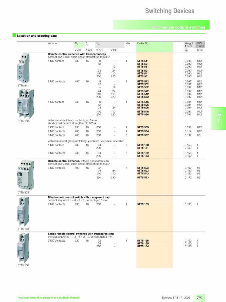
■ Selection and ordering data
Version Ue Ie Uc MW Order No. Weight PS*/P. unit1 item
V AC A AC V AC V DC kg Items
5TT5 511
5TT5 150
Remote control switches with transparent capcontact gap 3 mm, short-circuit strength up to 800 A
1 NO contact 230 16 8 – 1 5TT5 511 0.090 1/1212 – 5TT5 501 0.090 1/12
– 12 5TT5 551 0.090 1/12
24 24 5TT5 521 0.090 1/12110 110 5TT5 541 0.090 1/12230 220 5TT5 531 0.090 1/12
2 NO contacts 400 16 8 – 1 5TT5 512 0.097 1/1212 – 5TT5 502 0.097 1/12
– 12 5TT5 552 0.097 1/12
24 24 5TT5 522 0.097 1/12110 110 5TT5 542 0.097 1/12230 220 5TT5 532 0.097 1/12
1 CO contact 230 16 8 – 1 5TT5 516 0.091 1/1212 – 5TT5 506 0.091 1/1224 24 5TT5 526 0.091 1/12
110 110 5TT5 546 0.091 1/12230 220 5TT5 536 0.091 1/12
with central switching, contact gap 3 mm, short-circuit current strength up to 800 A
1 CO contact 230 16 230 – 1 5TT5 535 0.091 1/12
2 NO contacts 400 16 230 – 1 5TT5 534 0.114 1/12
3 NO contacts 400 16 230 – 2 5TT5 537 0.137 1/6
with central and group switching, � contact, very quiet operation
1 NO contact 230 16 24 – 2 5TT5 150 0.150 1230 – 5TT5 151 0.150 1
2 NO contacts 230 16 24 – 2 5TT5 152 0.150 1230 – 5TT5 153 0.150 1
5TT5 503
Remote control switches, without transparent capcontact gap 3 mm, short-circuit strength up to 800 A
3 NO contacts 400 16 22 – 2 5TT5 503 0.150 1/624 24 5TT5 523 0.150 1/6
110 110 5TT5 543 0.150 1/6
230 230 5TT5 533 0.150 1/6
5TT5 163
Blind remote control switch with transparent capcontact sequence 1 – 0 – 2 – 0, contact gap 3 mm
2 NO contacts 230 16 230 – 1 5TT5 163 0.100 1
5TT5 166
Series remote control switches with transparent capcontact sequence 1 – 2 – 1 + 2 – 0, contact gap 3 mm
2 NO contacts 230 16 12 – 1 5TT5 166 0.100 124 – 5TT5 165 0.100 1
230 – 5TT5 164 0.100 1

5TT5 remote control switches
7/6 Siemens ET B1 T · 2005
Switching Devices
* You can order this quantity or a multiple thereof.
■ Selection and ordering data
Version Ue Ie Uc MW Order No. Weight PS*/P. unit1 item
V AC A AC V AC V DC kg Items
5TT5 650
Electronic series remote control switch with transparent cap
contact sequence 1 – 2 – 1 + 2 – 0, �-contacts
2 NO contacts 230 16 12 – 1 5TT5 650 0.100 1
5TT5 601
5TT5 613
5TT5 621
Remote control system switches with transparent cap, �-contact, very quiet operation
1 NO contact 230 16 24 – 1 5TT5 601 0.065 1230 – 5TT5 602 0.065 1
12 – 5TT5 603 0.073 1
with 2 switching systems
1 NO contact per switching system
230 10 24 – 1 5TT5 605 0.080 1230 – 5TT5 606 0.065 1
12 – 5TT5 607 0.073 1
with central switching
1 NO contact 230 10 230 – 1 5TT5 611 0.065 1
with central switching, with 2 switching systems
1 NO contact per switching system
230 8 230 – 1 5TT5 612 0.080 1
with central switching, with 3 switching systems
1 NO contact per switching system
230 10 230 – 2 5TT5 613 0.140 1
with central switching, with 3 switching systems
1 NO contact per switching system
230 10 230 – 2 5TT5 614 0.160 1
with central and group switching, with transparent cap
1 NO contact 230 10 230 – 1 5TT5 621 0.065 1
with central and group switching, with 3 switching systems
1 NO contact per switching system
230 10 230 – 2 5TT5 623 0.140 1
5TG8 230
Compensator, mounting depth 55 mm
PTC resistor combination for increasing glow lamp loads
230 – – – 1 5TG8 230 0.050 1
5TG8 236 5TG8 238
Transparent caps
Spare part for devices with an overall width of 1 MW 5TT5 5.Only for devices with an overall width of 1 MW. 1 set(1 set = 5 items) 1 5TG8 236 0.025 1 set
Spare part for 5TT3 0., 5TT3 1, 5TT3 4., 5TT5 1. and 5TT5 6.devices with an overall width of 1 MW 2 transparent caps are required for 5TT5 1. devices with an overall width of 2 MW 1 set(1 set = 5 items) 1 5TG8 237 0.025 1 set
Spare part for 5TT3 4., 5TT5 6. and 5TT6 1.deviceswith an overall width of 2 MW 1 set(1 set = 5 items) 2 N 5TG8 238 0.045 1 set

5TT5 remote control switches
7/7Siemens ET B1 T · 2005
Switching Devices 12
345678910111213
■ Dimensional drawings
5TT5 5 remote control switches
5TT5 remote control switches, central ON/OFF 5TT5 16 blind and series remote control switches/5TT5 650 electronic series remote control switch
5TT5 6 remote control switch system
� � � �
� �
� � �
� � �
�
� � �
�� � �
�
� �
�
� � �
� �
� � � � �
3618 18 18 7 2444
64
I2_1
1585
45 67 90
5TT5 5015TT5 5115TT5 5215TT5 5315TT5 5415TT5 551
5TT5 5025TT5 5125TT5 5225TT5 5325TT5 5425TT5 552
5TT5 5035TT5 5235TT5 5335TT5 543
5TT5 5065TT5 5165TT5 5265TT5 5365TT5 546
� �
� � �
�
� �
�
� � �
� �
� �
� � � �� � � �
� � � �
� � � �
� � ��
1818 36 18 7 2444
64
I2_1
1586
45 67 905TT5 534 5TT5 535 5TT5 537 5TG8 230
compensator
18
A1A2
13
14
23
24
5 4364
45 90
I2_1
1587
5TT5 1635TT5 1645TT5 1655TT5 1665TT5 650
5 4364
45 90
I2_1
1588
36
L
36
ZE
1 4 241 4
N
ZAZE ZA
L N
1 3 23GE GA1 3QEQA
5TT5 1505TT5 151
5TT5 1525TT5 153
3618 18
ZA
T1
13
14
T1 T2
13
14
N
24
ZE ZA
T1 T2 T3
13 43
14
N
23
24
33
34
18 18
N
T1
13
14
N
T1 T2
13
14
23
24
ZE
N
ZAZE
36
ZE ZA
T1 T2 T3
13
14
N
23
24
33
34
18
ZEZA
T1GE
13 N
14GA
36
ZE ZA
T1 T2 T3
GE
13 N
14
GA
23
24
33
34
T4
44
5 4364
45 90
I2_1
1589
5TT5 6015TT5 6025TT5 603
5TT5 6055TT5 6065TT7 607
5TT5 611 5TT5 612 5TT5 613 5TT5 614 5TT5 621 5TT5 623

5TT5 remote control switches
7/8 Siemens ET B1 T · 2005
Switching Devices
■ Schematics
Switching example: 5TT5 602
Single-phase lighting circuit with 230 V AC actuation, e.g. in office buildings
Switching example: 5TT5 535 with central ON/OFF switching
With the 2-pushbutton central "ON" and "OFF" function, all remote control switches can be switched on or off from a central point, e.g. at the start and end of work. A time switch with a one-second pulse can also be used if desired. Once a central on/off switching has been executed, the remote control switches can also be switched on and off locally at any time. The phase relation of ZA, ZE and A1 is arbitrary.
5TT5 5. 1 5TT5 5. 2 5TT5 5. 3 5TT5 5. 6 5TT5 535 5TT5 534 5TT5 537
5TT5 1505TT5 151
5TT5 1525TT5 153
5TT5 16 5TT5 6015TT5 6025TT5 603
5TT5 6055TT5 6065TT5 607
5TT5 611 5TT5 612
5TT5 613 5TT5 614 5TT5 621 5TT5 623
5TT5 431 5TG8 230
�� �
�� � ��
�� �
�
�
� ��
�� �
�
�
� �
�
��
��
�
� � ���
�
�
���
� ���
�
�
�
�
�
���
�
�
�
�
� �
�
�
��
���
� �
�
��
�� ��
��
�
� � ��
�� ��
��
��
��
��
��
��
�
��
��
��
��
��
��
� �
��
����
� ��
��
�
��
��
��
����
���
�
�
��
��
�
��
��
��
���
���
��
�
��
��
��
��
�
��
��
�
��
��
��
���
���
��
�
��
��
��
��
��
�� ��
� �
��
���
� �
��
��
�
��
���
���
��
�
�
��
�� ��
��
�� ��
�
14
13
A2
A1
��
��
��
�� �
����
��
��
�
�
��
�
�����������
�
���
���
��
�
�� �� ��
�
��
�
���
�
�
��
�
���
�
�������������

5TT5 remote control switches
7/9Siemens ET B1 T · 2005
Switching Devices 12
345678910111213
■ Schematics
Switching example: 5TT5 153 with central ON/OFF switching
With the 2-pushbutton central "ON" and "OFF", all remote control switches can be switched on or off from a central point, e.g. at the start and end of work. With the 2 pushbutton group "ON" and "OFF" function, all remote control switches assigned to the respective group, e.g. halls, are switched on/off. A time switch with a one-second pulse can also be used with the "central" and "group" function if desired.
Once a central on/off switching has been executed, the remote control switches can also be switched on and off locally at any time. The phase relation of ZA, ZE and GA, GE and L do not have to be the same. If the contact 13/14 is used for the central "ON" and "OFF" function as a check-back contact, as shown above, terminals 13 of all remote control switches must be in-phase.
Switching example: 5TT5 623
The 5TT5 623 remote control switch comprises 3 separately control-lable remote control switches for central/group ON/OFF with housing-internal wiring of the central/group ON/OFF function. In our example, we have used pushbuttons to control the central/group ON/OFF function. However, if the room pushbuttons T1 to T3 are to
be permanently locked, then switches must be used for the central/group ON/OFF function instead of pushbuttons. Voltage must not be applied to ZA/ZE and GA and GE simultaneously. This type of prior-ity, the permanent locking of system pushbuttons, e.g. prisons, se-curity areas (banks, exhibitions), should only be switched centrally.
� �
�
� �
� �
� �� � �
� �� �
�
� �� �
� �� � �
� �� �
�
� �� �
� �� � �
� �� �
�
� �� �
� � � � � � � �
� � � � � � � � � �
�
� � � � � � �� � � � � �
� � � � � � �� � � � � �
� � � � � � �� � � � � �
33
34
T323
24
T213
14
T1 ZA ZE GA GE
L1 L3 NL2
N
I2_07269b
3x AC 230 V
A
Central/GroupON/OFF

5TT5 remote control switches
7/10 Siemens ET B1 T · 2005
Switching Devices
■ Schematics
Switching example: triple tap-changing gear and neutral position - 1, 2 and 3
Devices required:• 5TT5 164 series remote control switch• 5TT3 065 or 5TT3 075 switching relay• 5TE5 804 light indicator
Switching example: quadruple tap-changing gear - 1, 2, 3 or 4
Devices required:• 5TT5 164 series remote control switch• 5TT3 065 or 5TT3 075 switching relay• 5TE5 804 light indicator
���
��� ���
������
� �
���� ��
���
���
������
�
�
���� �����
��� ���
������
� � �
���
���
�����
�
�
�

5TT5 remote control switches
7/11Siemens ET B1 T · 2005
Switching Devices 12
345678910111213
■ Schematics
Switching example: 5TT5 511
Single-phase lighting circuit with safety extra-low voltage 8 V AC, pushbutton and glow lamp.
Switching example: 5TT5 535 with ON/OFF time switching
Printers and copiers are to be switched on with the pushbutton at the beginning of the working day. At the end of the working day, e.g.6 p.m. to 10 p.m., an hourly one-second pulse of the time switch switches the outlet off. This ensures that printers and copiers are not "forgotten". If the device is switched on again after 6 p.m., a switch-off is actuated again hourly.
Switching example: 5TT5 613 with central ON/OFF switching
The 5TT5 613 remote control switch comprises 3 separately control-lable remote control switches for central ON/OFF switching with housing-internal wiring of the central ON/OFF function. In our example, pushbuttons have been used to control the central ON/OFF function. However, if room pushbuttons T1 to T3 are to be permanently locked, switches must be used for the central ON/OFF function instead of pushbuttons. Voltage must not be applied simultaneously to the ZA and ZE terminals. Suitable switches are the 5TE7 141 group switches with center position or double changeover switches for wall mounting.
�
�
���
��
���
�
��
������
����� ��
���
��
�
�
�
���� ��
�� �
�
�
�
�
�
�
�
������ �
�����
�����
�����
���� ��
� �
� �
� �� �
� �
� �
� � � � � � �
� �
� �
� � � �
� � � � �� �
�
� � � � � � � � � � � � � � � � � �� � � � � �
�

5TT5 remote control switches
7/12 Siemens ET B1 T · 2005
Switching Devices
■ Schematics
Glow lamp load and line capacity
When the pushbutton is open, the glow lamps in the pushbuttons draw their current over the magnet coil of the remote control switch. If the current is too high, this can prevent the armature from dropping. The 5TG8 230 compensator, which is switched in parallel to the magnet coil, discharges the current.
�
�� �
����
��
�
�� �
� �
��
�� �� ���������� ����������
����� �������

5TT3 0 switching relays
7/13Siemens ET B1 T · 2005
Switching Devices 12
345678910111213
■ Overview
FunctionSwitching relays are used in control systems as coupling relays, for the electrical or safe isolation of electrical circuits.
Safe isolationThe magnet coil and the contacts meet the requirements for safety extra-low voltage from the actuating voltage safely through to disconnection.
Checking functions using the manual switchSwitching relays have a manual switch that shows the switching position. This switch can be used to manually switch the switching relay, thus allowing system devices and control functions to be checked.
■ Technical specifications
Acc. to EN 60255 (VDE 0435) 5TT3 05. 5TT3 040 5TT3 081 5TT3 0855TT3 06.5TT3 07.5TT3 080
Rated control supply voltage Uc V AC 8, 12, 24, 110 or 230V DC 12, 24, 30 or 110, depending on type
Operating range × Uc 0.9 ... 1.1
Rated power dissipation Pv pick-up power, approx. 20 msholding power per contact
VAVAVA
2.11.31
1.11.81
2.11.31
1.11.81
Rated frequency AC versions Hz 50
Response time/returning time ms 30
Contact gap mm �-contact
Rated operational voltage Ue 1-pole V AC 250
Safe isolation creepage distances and clearances magnet coil/contact
mm > 8
Different phases magnet coil/contact permissible
Rated operational current Is for p. f. = 1 A 16
Rated impulse withstand voltage Uimp magnet coil/contactcontact/contact
kVkV
>4>2.5
Minimum contact load V; mA 10; 100
Terminals ± screw (Pozidrive) 1
Conductor cross-sections rigidflexible with sleeve
max. mm2
min. mm22 x 2.50.5
Permissible ambient temperature °C -20 ... +45
Protection class acc. to EN 60730-1 IP20
Degree of protection acc. to EN 60529 II
Humidity class acc. to DIN 50016acc. to IEC 60068-2-30
FW 24
Switching Devices
5TT3 0 switching relays
7/14 Siemens ET B1 T · 2005
Switching Devices
■ Technical specifications
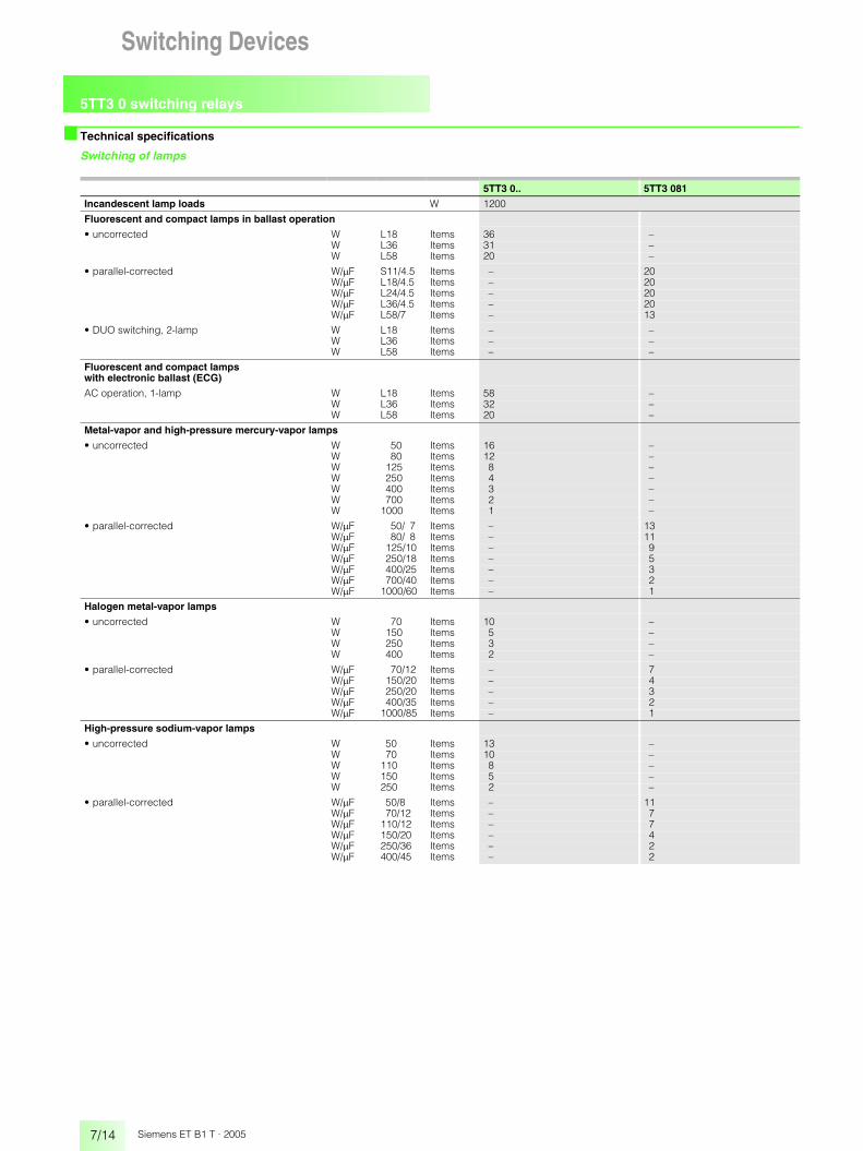
Switching of lamps
5TT3 0.. 5TT3 081
Incandescent lamp loads W 1200
Fluorescent and compact lamps in ballast operation
• uncorrected W L18 Items 36 –W L36 Items 31 –W L58 Items 20 –
• parallel-corrected W/�F S11/4.5 Items – 20W/�F L18/4.5 Items – 20W/�F L24/4.5 Items – 20W/�F L36/4.5 Items – 20W/�F L58/7 Items – 13
• DUO switching, 2-lamp W L18 Items – –W L36 Items – –W L58 Items – –
Fluorescent and compact lamps with electronic ballast (ECG)
AC operation, 1-lamp W L18 Items 58 –W L36 Items 32 –W L58 Items 20 –
Metal-vapor and high-pressure mercury-vapor lamps
• uncorrected W 50 Items 16 –W 80 Items 12 –W 125 Items 8 –W 250 Items 4 –W 400 Items 3 –W 700 Items 2 –W 1000 Items 1 –
• parallel-corrected W/�F 50/ 7 Items – 13W/�F 80/ 8 Items – 11W/�F 125/10 Items – 9W/�F 250/18 Items – 5W/�F 400/25 Items – 3W/�F 700/40 Items – 2W/�F 1000/60 Items – 1
Halogen metal-vapor lamps
• uncorrected W 70 Items 10 –W 150 Items 5 –W 250 Items 3 –W 400 Items 2 –
• parallel-corrected W/�F 70/12 Items – 7W/�F 150/20 Items – 4W/�F 250/20 Items – 3W/�F 400/35 Items – 2W/�F 1000/85 Items – 1
High-pressure sodium-vapor lamps
• uncorrected W 50 Items 13 –W 70 Items 10 –W 110 Items 8 –W 150 Items 5 –W 250 Items 2 –
• parallel-corrected W/�F 50/8 Items – 11W/�F 70/12 Items – 7W/�F 110/12 Items – 7W/�F 150/20 Items – 4W/�F 250/36 Items – 2W/�F 400/45 Items – 2

5TT3 0 switching relays
7/15Siemens ET B1 T · 2005
Switching Devices 12
345678910111213
* You can order this quantity or a multiple thereof.
■ Selection and ordering data
1) Spare transparent cap, see Page 7/6.
Design Ue Ie Uc MW Order No. Weight 1 item
PS*/P. unit
V AC A AC V AC V DC kg Items
5TT3 041
5TT3 061
Switching relays with transparent cap 1)
1 NO contact 230 16 8 – 1 5TT3 041 0.100 112 – 5TT3 042 0.100 124 – 5TT3 043 0.100 1
110 – 5TT3 044 0.100 1230 – 5TT3 045 0.100 1
2 NO contacts 230 16 8 – 1 5TT3 051 0.100 112 – 5TT3 052 0.100 124 – 5TT3 053 0.100 1
110 – 5TT3 054 0.100 1230 – 5TT3 055 0.100 1
1 CO contact 230 16 8 – 1 5TT3 061 0.100 112 – 5TT3 062 0.100 124 – 5TT3 063 0.100 1
110 – 5TT3 064 0.100 1230 – 5TT3 065 0.100 1
2 CO contacts 230 16 8 – 1 5TT3 071 0.100 112 – 5TT3 072 0.100 124 – 5TT3 073 0.100 1
110 – 5TT3 074 0.100 1230 – 5TT3 075 0.100 1
for control with direct voltage
2 CO contacts 230 16 – 12 1 5TT3 078 0.105 1– 24 5TT3 076 0.100 1
– 30 5TT3 082 0.120 1– 110 5TT3 077 0.100 1
for switching capacitive loads; of lighting
1 NO contact 230 16 230 – 1 5TT3 081 0.100 1
for control of PLCscontact: 15 to 60 V, 2 to 30 mA according to EN 61131-2, type 1
1 NO contact 230 16 230 – 1 5TT3 085 0.110 1
5TT3 080
Sealable enable relay, mounting depth 55 mm
used for boiler /storage relaysIn the case of continuous duty, a distance of 1 MWmust be maintained between the devices.
1 CO contact 230 16 230 – 1 5TT3 080 0.100 1
5TT3 0 switching relays
7/16 Siemens ET B1 T · 2005
Switching Devices
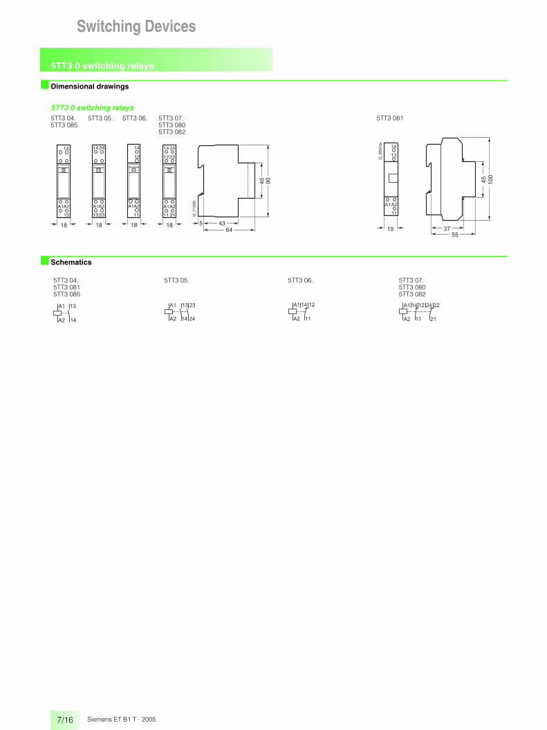
■ Dimensional drawings
■ Schematics
5TT3 0 switching relays
18
14
18
14 24
2212 12
11
A1A2
11 21
18
14
18
14 24
23
A1A2
13 13
A1A2 A1A2
5 4364
45 90
I2_1
1590
5TT3 04.5TT3 085
5TT3 05. 5TT3 06. 5TT3 07.5TT3 0805TT3 082
��
��
�
����
� �
��
�
��
��
����
5TT3 081
5TT3 04.5TT3 0815TT3 085
5TT3 05. 5TT3 06. 5TT3 07.5TT3 0805TT3 082
��
��
�
��
��
�� ��
� �
��
��
��
��
���
��
��
��
���
��
���

5TT5 7 Insta contactors
7/17Siemens ET B1 T · 2005
Switching Devices 12
345678910111213
■ Overview
Low-noise contactors, 24, 40 and 63 A devicesThe 5TT5 73., 5TT5 74. and 5TT5 75. Insta contactors are equipped with a DC magnetic system. Apart from a very quiet switching noise, they are noise-free. They are therefore especially suitable for appli-cations in residential buildings.
SpacersSpacers can be used as a balancing element and have a width of ½ MW. They come with an integrated wiring duct for the insertion of conductors. Two oppositely installed spacers thus offer space for large conductor cross-sections up to a 14 mm diameter.
Heat dissipation If Insta contactors are installed in distribution boards, they should be designed for a standard temperature of 40 °C. If more than one Insta contactor is installed, a 5TG8 240 spacer must be installed after every second contactor.
Switching Devices

5TT5 7 Insta contactors
7/18 Siemens ET B1 T · 2005
Switching Devices
■ Technical specifications
Switching of direct voltages DC-1
5TT5 70 5TT5 73 5TT5 74 5TT5 752-pole 4-pole 4-pole 4-pole
Rated control supply voltage Uc V AC 24, 230 24, 115, 230 24, 230V DC – 24, 110, 220 24, 220
Operating range � Uc 0.85 ... 1.1
Rated operational voltage Ue V 250 440 440 440
Rated operational current Ie
• AC-1/AC-7a, NO contacts A 20 24 40 63• AC-1/AC-7a, NC contacts A 20 24 30 30• AC-3/AC-7b, NO contacts A 9 9 22 30• AC-3/AC-7b, NC contacts A 9 6 – –
Rated power dissipation Pv
• Pick-up power VA 8 4 5 65• Holding power VA 3.2 4 5 4.2• per contact AC-1/AC-7a VA 1 1.5 3 6
Rated frequency at AC Hz 50
Switching times
• closing (NO contacts) ms �12 �40 �40 �40• opening (NO contacts) ms �12 �40 �40 �40
Rated impulse withstand voltage Uimp kV �4 �4
Contact gap (NO contacts) min. mm 1.5 2.4 2.8 2.6
Electrical service life
for switching cycles at Ie and load AC-1 100.000 100.000 50.000 50.000
Switching of resistive loads AC-1 V AC 230 230 230 230
for rated operational power Ps (NO contacts) 1-phase kW 4 5.3 8.8 13.83-phase kW – 16 26 41
Switching of three-phase asynchronous motors AC-3 V AC 230 400 400 400
for rated operational power Ps (NO contacts) 1-phase kW 1.3 – – –3-phase kW – 4 11 15
Overload withstand capability
per current path (NO contacts only) at 10 s A 72 72 176 240
Short-circuit protection, acc. to coordination type 1
back-up fuse characteristic gL/gG A 20 35 63 80
Terminals
• ± screw (Pozidrive) 1 1 1 1• 1 1 2 2
Tightening torque
• coil connection Nm 0.9 0.9 0.9 0.9• main connection Nm 1.2 1.0 2.5 2.5
Conductor cross-sections
• coil connection rigid mm2 1.0 ... 2.5 1.5 ... 4 1.5 ... 4 1.5 ... 4rigid mm2 1.0 ... 2.5 1.5 ... 2.5 1.5 ... 2.5 1.5 ... 2.5
• main connection rigid mm2 1.0 ... 4 1.5 ... 10 2.5 ... 25 2.5 ... 25flexible with sleeve mm2 1.0 ... 4 1.5 ... 6 2.5 ... 16 2.5 ... 16
Permissible ambient temperature
• for operation °C -25 ... +55 -25 ... +55 -25 ... +55 -25 ... +55• for storage °C -40 ... +70 -50 ... +80 -50 ... +80 -50 ... +80
Degree of protection acc. to EN 60529 IP20
Permissible DC switching currents for NO contacts at p. f. = 1 4 contacts in series are not recommended for 24 V due to unreliable contacts
1 contact 2 contactsin series
3 contactsin series
4 contactsin series
5TT5 70, 2-pole, 20 A Ie at Ue =24 V DC A 20 20 – –Ie at Ue = 220 V DC A – – – –
5TT5 73, 4-pole, 24 A Ie at Ue =24 V DC A 24 24 24 24Ie at Ue =110 V DC A 2 4 6 8Ie at Ue = 220 V DC A 0.5 1.5 2.5 3.5
5TT5 74, 4-pole, 40 A Ie at Ue =24 V DC A 40 40 40 40Ie at Ue = 220 V DC A 0.8 5 15 18
5TT5 75, 4-pole, 63 A Ie at Ue =24 V DC A 50 63 63 63Ie at Ue = 220 V DC A 0.8 5.5 17 20

5TT5 7 Insta contactors
7/19Siemens ET B1 T · 2005
Switching Devices 12
345678910111213
■ Technical specifications
Switching of lamps
Maximum number of lamps, per conducting path at 230 V AC, 50 Hz.
Fluorescent and compact lamps in ballast operation
Fluorescent and compact lamps with electronic ballast (ECG)
High-pressure mercury-vapor lamps
Halogen metal-vapor lamps
High-pressure sodium-vapor lamps
Incabdescent lamp loads
5TT5 70, 2-pole, 20 A per current path W 1000
5TT5 73, 4-pole, 24 A per current path W 1000
5TT5 74, 4-pole, 40 A per current path W 3000
5TT5 75, 4-pole, 63 A per current path W 5000
Uncorrected Parallel-corrected DUO circuit2-lamp
Lamp type W L18 L36 L58 L18 L36 L58 L18 L36 L58Capacitor capacitance �F – – – 4.5 4.5 7.0 – – –
5TT5 70, 2-pole 20 A NO 22 14 10 6 5 4 17 11 10
5TT5 73, 4-pole 24A NO 24 20 12 8 8 5 24 20 12
5TT5 74, 4-pole 40 A NO 85 65 40 16 16 10 85 65 40
5TT5 75, 4-pole 63 A NO 135 95 60 67 67 43 140 95 60
1-lamp 2-lamp
Lamp type W L18 L36 L58 L18 L36 L58
5TT5 70, 2-pole 20 A NO 15 12 8 2 × 8 2 × 6 2 × 3
5TT5 73, 4-pole 24A NO 24 16 12 2 × 16 2 × 8 2 × 5
5TT5 74, 4-pole 40 A NO 55 30 22 2 × 20 2 × 10 2 × 8
5TT5 75, 4-pole 63 A NO 76 42 30 2 × 24 2 × 13 2 × 9
Uncorrected Parallel-corrected
Lamp type W 50 80 125 250 400 700 1 000 50 80 125 250 400 700 1 000Capacitor capacitance �F – – – – – – – 7 8 10 18 25 45 60
5TT5 70, 2-pole 20 A NO 12 7 5 3 1 0 0 4 3 2 1 0 0 0
5TT5 73, 4-pole 24A NO 14 10 7 4 2 1 1 5 4 3 2 1 0 0
5TT5 74, 4-pole 40 A NO 36 27 19 10 7 4 3 10 8 6 3 3 1 1
5TT5 75, 4-pole 63 A NO 50 38 26 14 10 6 4 43 37 26 15 10 5 4
Uncorrected Parallel-corrected
Lamp type W 70 150 250 400 1 000 2000 70 150 250 400 1 000Capacitor capacitance �F – – – – – – 12 20 33 35 95
5TT5 70, 2-pole 20 A NO 0 0 0 0 0 0 0 0 0 0 0
5TT5 73, 4-pole 24A NO 5 3 2 1 0 0 3 1 1 0 0
5TT5 74, 4-pole 40 A NO 14 8 5 4 1 0 5 3 2 2 0
5TT5 75, 4-pole 63 A NO 20 11 7 6 2 1 18 9 5 4 1
Uncorrected Parallel-corrected
Lamp type W 150 250 400 1 000 150 250 400 1 000Capacitor capacitance �F - - - - 20 33 48 106
5TT5 70, 2-pole 20 A NO 0 0 0 0 0 0 0 0
5TT5 73, 4-pole 24A NO 4 3 1 0 1 1 0 0
5TT5 74, 4-pole 40 A NO 12 7 5 2 3 2 1 0
5TT5 75, 4-pole 63 A NO 19 11 7 3 15 9 6 2

5TT5 7 Insta contactors
7/20 Siemens ET B1 T · 2005
Switching Devices
* You can order this quantity or a multiple thereof.
■ Selection and ordering data
1) For NC contacts 30 A.
Design Ue Ie Uc MW Order No. Weight 1 item
PS*/P. unit
V AC A AC V AC V DC kg Items
5TT5 700-0
5TT5 730-0
5TT5 740-0
Insta contactors
for alternating current continuous operation, with switch position indication, with alternating current magnetic system
2 NO contacts 250 20 230 – 1 5TT5 700-0 0.132 124 – 5TT5 700-2 0.132 1
1 NO contact, 1 NC contact
250 20 230 – 1 5TT5 701-0 0.132 1
24 – 5TT5 701-2 0.132 1
2 NC contacts 250 20 230 – 1 5TT5 702-0 0.132 124 – 5TT5 702-2 0.132 1
for AC or DC continuous operation, with switch position indication, with DC magnetic system
4 NO contacts 440 24 230 220 2 5TT5 730-0 0.247 1115 110 5TT5 730-1 0.247 124 24 5TT5 730-2 0.247 1
3 NO contacts, 1 NC contact
440 24 230 220 2 5TT5 731-0 0.247 1
24 24 5TT5 731-2 0.247 1
2 NO contacts, 2 NC contacts
440 24 230 220 2 5TT5 732-0 0.247 1
24 24 5TT5 732-2 0.247 1
4 NC contacts 440 24 230 220 2 5TT5 733-0 0.247 124 24 5TT5 733-2 0.247 1
4 NO contacts 440 40 230 220 3 5TT5 740-0 0.410 124 24 5TT5 740-2 0.410 1
3 NO contacts, 1 NC contact
440 40 1) 230 220 3 5TT5 741-0 0.410 1
24 24 5TT5 741-2 0.410 1
2 NO contacts, 2 NC contacts
440 40 1) 230 220 3 5TT5 742-0 0.410 1
24 24 5TT5 742-2 0.410 1
4 NO contacts 440 63 230 220 3 5TT5 750-0 0.410 124 24 5TT5 750-2 0.410 1
3 NO contacts, 1 NC contact
440 63 1) 230 220 3 5TT5 751-0 0.410 1
24 24 5TT5 751-2 0.410 1
2 NO contacts, 2 NC contacts
440 63 1) 230 220 3 5TT5 752-0 0.410 1
24 24 5TT5 752-2 0.410 1
5TT5 900
Auxiliary switches
for left-sided mounting on the 24-A, 40-A and 63-A Insta contactor; max. one auxiliary switch per Insta contactor. minimum contact load 24 V AC; 5 mA
2 NO contacts 230, AC-15 4 0.5 5TT5 900 0.039 1
1 NO contact, 1 NC contact
230, AC-15 4 0.5 5TT5 901 0.039 1
5TG8 240
Spacer
for heat conduction between the Insta contactors. We recom-mend placing a spacer between each second Insta contactor. Can be mounted reciprocally, so that two spacers enable greater cable penetration
0.5 5TG8 240 0.010 2
5TT5 903
Sealable terminal covers 1 set
for Insta contactors 24 A, (1 set = 2 items) 2 5TT5 902 0.010 1 set
1 setfor Insta contactors 40 A and 63 A, (1 set = 2 items) 3 5TT5 903 0.010 1 set

5TT5 7 Insta contactors
7/21Siemens ET B1 T · 2005
Switching Devices 12
345678910111213
■ Dimensional drawings
■ Schematics
5TT5 7 Insta contactors
� �
� �
� �
� �
� � �
� �
� �
� � �
� � � �
� �
� �
� � � �
� � � � � �
�������
� � � � �
� ��
�
5TT5 700 5TT5 701 5TT5 702
� �� �
� �� �� �
� �� �� �
� �� �
� �� �
� �� �� �
� �� �� �
� �� �
��� �
�� �
�� �� �
�
� � � � � �
� � � � �� � � �
� � � �
� �� �� � � �
���������
� � � � �
� �
�
�
5TT5 730 5TT5 731 5TT5 732 5TT5 733
*) Without sealable terminal cover
� � � � �� � � �
� � � � � � � � � � � � � � � �
�������
� � � � � �
� �
�
�
� �
� � � �� � � � � � � � � � � � � � � � � � � � � � �
5TT5 7405TT5 750
5TT5 7415TT5 751
5TT5 7425TT5 752
� �
�
� �
�
� �
�
� �
�
�������
� � � � �
� �
�
�
5TT5 900 5TT5 901
5TT5 700 5TT5 701 5TT5 702 5TT5 7305TT5 7405TT5 750
5TT5 731 5TT5 7415TT5 751
5TT5 732 5TT5 7425TT5 752
5TT5 733 5TT5 900 5TT5 901
��
�� �
� �
�
��
�� �
� ��
��
��
�� ��
�� ��
��
� �
� � �
� �
� �
� �
� � �
� � � � �
� � �
� � �
� � �
� �
�
� �
� � �
� �
� �
�� �
� �
� �
� � � �
� � � �
� � � �
� � � �
� �
� �
� � � �
� � � �
� � � �
� � � �
� �
� �
� � � �
� � � �
� � � �
� � � �
� � �� ��
�� ��
�� ��
�� ��

5TT3 4 soft-starting devices
7/22 Siemens ET B1 T · 2005
Switching Devices
* You can order this quantity or a multiple thereof.
■ Overview • 1-phase 1.5 kW• 3-phase 5.5 kW• Increases the service life of one-phase asynchronous motors and
mechanical drive equipment• Can also be retrofitted in existing systems
• Separate setting of acceleration time and starting torque• With LED display for startup or continuous operation• The power semiconductors are bridged after completion of
start-up.
■ Technical specifications
1) For rated operational current.
■ Selection and ordering data
1) Spare transparent cap, see Page 7/6.
Data acc. to EN 60947-4-2 (VDE 0660 Part 117) 5TT3 440 5TT3 441
Supply/motor voltage V AC 400 230
Operating range × Uc 0.8 ... 1.1
Rated power VA 3.5 1.4
Rated frequency Hz 50/60
Rated power dissipation Pv coil/drive 3.5 1.7contact1) per pole 4.6 0.7
Max. rated motor power at 400 V VA 5500 1500
Min. rated motor power at 400 V VA 300 100
Startup voltage % 30 ... 70 20 ... 70
Starting ramp s 0.1 ... 10
Recovery time ms 100 200
Switching frequency
3 × IN, TAN = 10 s, �u = 20 % switching cycles/h
36 (to 3 kW) 10
3 × IN, TAN = 10 s, �u = 20 % switching cycles/h
20 (from 3 ... 5.5 kW)
Semiconductor fuse super quick A 35 20
Conductor cross-sections rigid max. mm2 2 × 2.5flexible with sleeve min. mm2 1 × 0.5
Permissible ambient temperature °C -20 ... +60 -20 ... +55
Resistance to climate acc. to EN 60068-1 20/60/4 20/55/4
Design Ue Pc MW Order No. Weight 1 item
PS*/P. unit
V AC W kg Items
5TT3 441
Soft-starting device with transparent cap 1)
1-phase 230 100 ... 1 500 2 5TT3 441 0.135 1
5TT3 440
Soft-starting device, mounting depth 55 mm
3-phase, 2-phase motor actuation 400 300 ... 5 500 6 5TT3 440 0.430 1
NL1
T2T1
I2_07513
tacc Mst
tacc: Acceleration time
Mst: Starting torque
A
L1L2L3
T1T2T3
I2_07514
tacc Mst
tacc: Acceleration time
Mst: Starting torque
A
Switching Devices

5TT3 4 soft-starting devices
7/23Siemens ET B1 T · 2005
Switching Devices 12
345678910111213
■ Dimensional drawings
5TT3 44 soft-starting devices
■ Schematics
Switching example: 5TT3 440
The soft-starting device is an electronic control for the soft startup of three-phase asynchronous machines. Two of three phases are in-fluenced by the phase control such that the current rises steadily. This also increases the motor torque and the drive starts up smooth-ly.Because drive elements are handled more gently, they can be designed more cost-effectively. As well as a considerable reduction in startup noise, this also helps prevent the tipping or sliding of materials to be transported. The starting current is minimized.To prevent losses in the device, the power electronics are bridged with relay contacts after startup.Note: There is no speed adjustment. There is no marked soft start behavior without a mechanically connect load. In the case of high switching frequencies, we recommend installing a thermistor motor protection for monitoring the permissible motor temperature.The soft-starting device must not be operated with capacitive load.There must be no source of heat located underneath the device.However, soft-starting devices can be arranged next to each other.
Switching example: 5TT3 441
The soft-starting device is an electronic control for the soft startup of one-phase asynchronous machines. A phase control causes the current to rise steadily. This also increases the motor torque and the drive starts up smoothly.Because drive elements are handled more gently they can be designed more cost-effectively. As well as a considerable reduction in startup noise, this also helps prevent the tipping or sliding of materials to be transported. The starting current is minimized.To prevent losses in the device, the power electronics are bridged with relay contacts after startup.Note:There is no speed adjustment. There is no marked soft start behavior without a mechanically connect load. If the power semiconductor is to be protected against short circuits or ground faults during startup, a super-quick fuse must be installed. Otherwise, the usual line and motor protective measures must be used. In the case of high switch-ing frequencies, we recommend installing a thermistor motor protec-tion for monitoring the permissible motor temperature.The soft-starting device must not be operated with capacitive load.In order to ensure the safety of persons and systems, only suitably qualified personnel should work on these devices.
5 4355
45 90
I2_1
1594
L1 L2 L3
T1 T2 T3
105
5TT3 440
5 4364
45 90
I2_1
1595
L1 N
T1 T2
36
5TT3 441
L1
5TT3 440
L2 L3
T1 T2 T3
K2 K1
K2K1
K2K1
0 RLS
PE 3 ~
�
L1
L2
L3
N
PE
I2_07281a3 AC 230/400 A
Reversingswitch
��������
�����
� �
�� ��
��
��
�
���
�
�
�
��
��
��
��
��
��
�������

5TT5 2 EMERGENCY-STOP modules
7/24 Siemens ET B1 T · 2005
Switching Devices
■ Overview
RegulationsThe machine Directive 98/37/EG, valid from 31.12.1994, only speci-fies global safety standards. Details on how to implement individual safety demands are defined in standards, e.g. by the European Committee for Electrotechnical Standardization (CENELEC), which are based on international standards.
Key standards• EN 60204-1 (VDE 0113 Part 1):1998
"Machine safety – Electrical equipment of machinery Part 1: General requirements"
• EC Directive machinery 98/37/EG• EN 292-1:1991
"Basic concepts, general principles for design Part 1: Basic terminology, methodology"
• EN 292-2:1991 and EN 292-2/A1:1995 "Basic concepts, general principles for design Part 2: Technical principles and specifications"
• EN 418:1992 "Safety of machinery – Emergency stop equipment, functional aspects, principles for design"
• EN 954-1:1996 "Safety of machinery – Safety-related parts of control systems Part 1: General principles for design"
• EN 1088:1995 "Safety of machinery – Interlocking devices associated with guards – Principles for design and selection"
Category of safety-related parts of control systems acc. to CEN/TC 114 EN 954-1
Category Summary of requirements System behavior
B The safety-related parts of machine control systems and/or their protective devices and their components must be state of the art and designed, selected, assembled and combined such that they can withstand the expected influences.
The occurrence of a fault can lead to the loss of the safety function. Some faults remain undetected.
1 The requirements of B must be fulfilled. Use of proven safety components and principles.
As described for category B, but with a higher level of safety-related reliability
2 The requirements of B must be fulfilled and tried and tested safety principles must be implemented.The safety functions must be tested at suitable intervals by the control system of the machine.
Note: What is considered suitable depends on the application and the type of machine.
The occurrence of a fault can lead to the loss of safety function between testing intervals. The fault is detected by the test.
3 The requirements of B must be fulfilled and tried and tested safety principles must be implemented. The control systems must be designed so that:
If a single fault occurs, the safety function is always maintained.Some, but not all, faults are detected.An accumulation of undetected faults may lead to the loss of the safety function.
a) A single fault in the control system does not lead to the loss of the safety function(s) and
b) Wherever practically possible, the single fault is detected by the appropriate means, which must be state-of-the-art.
4 The requirements of B must be fulfilled and tried and tested safety princi-ples must be implemented. A control system must be designed so that:
If faults occur, the safety function is always maintained. The faults are detected in time to prevent the loss of the safety function.
a) A single fault in the control system does not lead to the loss of the safety function(s) and
b) Whenever possible, a single fault is detected at or before the next request for the safety function or
c) If b) is not possible, that an accumulation of faults does not lead to the loss of the safety function.
Switching Devices

5TT5 2 EMERGENCY-STOP modules
7/25Siemens ET B1 T · 2005
Switching Devices 12
345678910111213
■ Overview
ScopeThe scope of the EC Directive Machines is no longer restricted to in-dustrial machinery, but now covers virtually all machines used in all areas of commercial and private trade and industry and applies to all• stationary• movable,• hand-held,• mobile• machine tools and processing machines• prime movers and production machines• compressors
• operating and packaging machines• machines in underground mining• earthmoving machines and harvesters• hoisting equipment• floor conveyors• machines for lifting persons• plants• interchangeable equipment, such as snow ploughs and mountable
sweeping devices
Risk analysis and selection of a suitable categoryEngineers and operators assume responsibility for the correct risk assessment.It is difficult to make a quantitative assessment of the risk, so that when selecting the category, the reasonable risk can be determined within a broad band width.
This becomes clear if you select "F2 - frequently to continuous" instead of "F1 - rarely to frequently", for the risk parameters "F - Fre-quency and duration" when drawing up a risk graph (see image).The whole band width of safety categories may lie between the assessment of "often" and "frequently".
■ Benefits• Acc. to the 98/37/EC EC directive for machines• Safety category 4 acc. to EN 954-1• Acc. to the 98/37/EC EC directive for machines
• Safety category 4 acc. to EN 954-1• Electrical isolation between electric circuit and control• LED display for operation and circuit state
■ Technical specifications
1) For rated operational current.
I2_0
8404
a
B 1 2 3 4
minor injury
serious and irreversible injury of one or several persons or death of a person
rarely to frequently
frequently to constantly
possible under certain circumstances
possible under certaincircumstances
hardly possible
preferred categories for reference points
possible category which requiresadditional measures with regard to the risk
overdimensioned measures with regard to the risk
Categories
hardly possible
seriousness of injuryRisk parameter F: Risk parameter P:frequency andduration
possibility of avoiding injuries
Risk parameter S:
Data acc. to IEC 60204-1; EN 60204-1 (VDE 0113 Part 1) 5TT5 200
Rated control voltage Uc V AC 230
Rated power dissipation Pv coil/drive 3.5contact 1) per pole 0.8
Operating range × Uc 0.8 ... 1.1
Rated frequency Hz 50
Control supply voltage terminal Y1 V AC/DC 24
Control current terminal Y1 DC mA 45
Recovery time ms 500
Electrical isolation creepage and clearancesactuator/contact mm 3
Rated impulse withstand voltage Uimp actuator/contact kV > 4
Contact NO contact AC-15 A 3NCNO contact/NC contact
AC-15AC-1
AA
25
Contact gap mm > 1
Electrical service life AC-15, 2A, 230 V AC operating cycles
105
Reliable switching frequency switching cycles/h
600
Vibration strengthaccording to EN 60068-2-6 10 to 55 Hz amplitude in mm 0.35
Terminals +/- screw (Pozidrive) 1
Conductor cross-sections rigid max. mm2 2 × 2.5flexible with sleeve min. mm2 1 × 0.5
Permissible ambient temperature °C 0 ... +50
Resistance to climateacc. to EN 60068-1 0/55/04

5TT5 2 EMERGENCY-STOP modules
7/26 Siemens ET B1 T · 2005
Switching Devices
* You can order this quantity or a multiple thereof.
■ Selection and ordering data
■ Dimensional drawings
5TT5 200 emergency stop module
■ Schematics
Switching examples
Direct connection 230 V/400 V to 5 A
The monitoring logic checks internal relay contacts (not shown) to see whether both relays have been released prior to switching on. This ensures that no contacts are welded. In addition, the voltage level at terminal A1 is monitored. The parallel NC contacts K1 and K2 (terminals 41 and 42) can be connected as required.
Connection of external contactors
External contactors may be used when they are equipped with positively driven contacts according to safety regulations ZH1/457 of the German Trade Association (compare catalog ET B1 · 2002, Technical specifications, pages 6/15 or 6/20). Contactors with 3 NO contacts and 1 NC contact must be used, whereby the NC contacts must be integrated in the monitoring loop – terminals Y1/Y2. The par-allel NC contacts K1 and K2 (terminals 41 and 42) can be connected as required.
Design Ue Ie Uc MW Order No. Weight 1 item
PS*/P. unit
V AC A V AC kg Items
5TT5 200
EMERGENCY-STOP module, mounting depth 55 mm
400 5 230 4 5TT5 200 0.250 1
�� �
������
�������
�� �� �� �� �� ��
�� �� �� �� �� ��
��
���� ����
L1
A1 Y1 13 23 33 41
14 24 34 42
K2
K1
A2
N
I2_08435a
Y2
Monitoringlogic
Emergency-Stop
On
L1
A1 Y1 13 23 33 41
14 24 34 42
K2
K1
A2
N
I2_08436a
K3
K4
Y2
K4
K3
L1 L2 L3
N
Monitoringlogic
Emergency-Stop
On
Electrical switching
7/27Siemens ET B1 T · 2005
Switching Devices 12
345678910111213
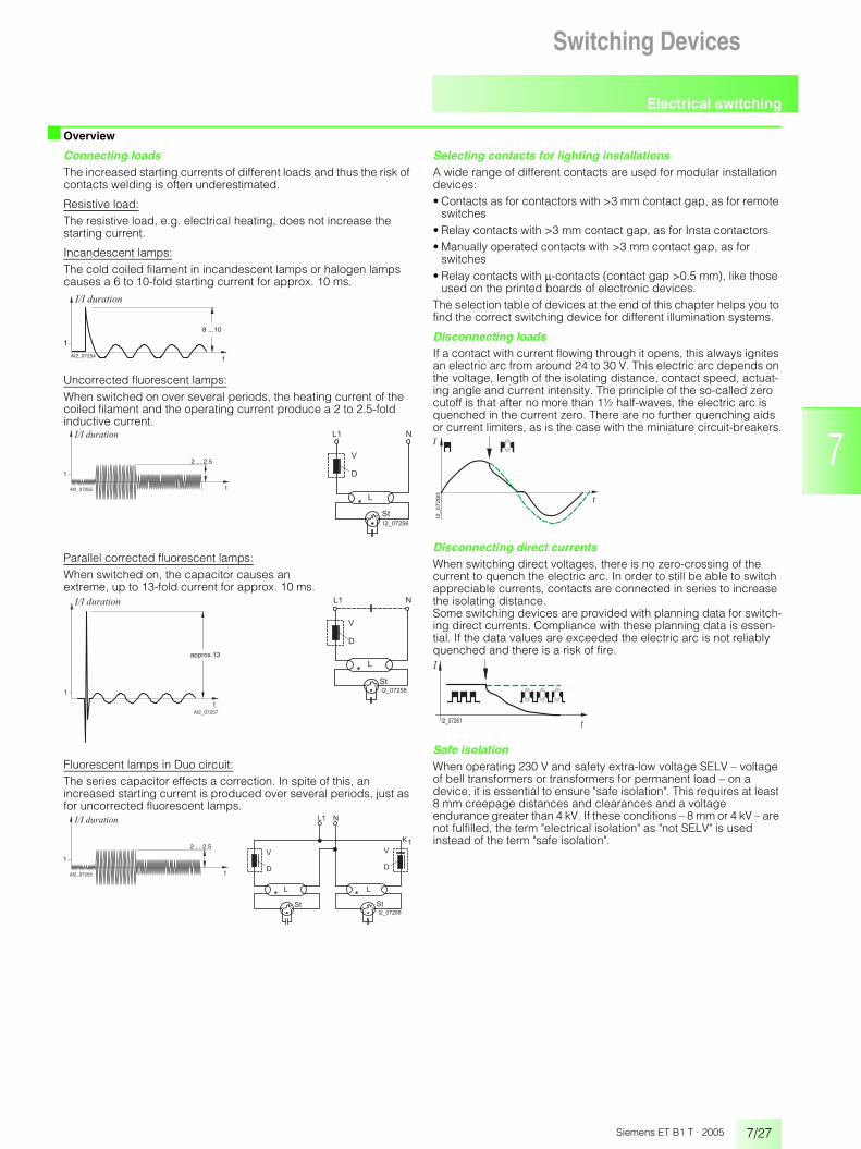
■ Overview
Connecting loadsThe increased starting currents of different loads and thus the risk of contacts welding is often underestimated.
Resistive load:The resistive load, e.g. electrical heating, does not increase the starting current.
Incandescent lamps:The cold coiled filament in incandescent lamps or halogen lamps causes a 6 to 10-fold starting current for approx. 10 ms.
Uncorrected fluorescent lamps:When switched on over several periods, the heating current of the coiled filament and the operating current produce a 2 to 2.5-foldinductive current.
Parallel corrected fluorescent lamps:When switched on, the capacitor causes an extreme, up to 13-fold current for approx. 10 ms.
Fluorescent lamps in Duo circuit:The series capacitor effects a correction. In spite of this, an increased starting current is produced over several periods, just as for uncorrected fluorescent lamps.
Selecting contacts for lighting installationsA wide range of different contacts are used for modular installation devices:• Contacts as for contactors with >3 mm contact gap, as for remote
switches• Relay contacts with >3 mm contact gap, as for Insta contactors• Manually operated contacts with >3 mm contact gap, as for
switches• Relay contacts with �-contacts (contact gap >0.5 mm), like those
used on the printed boards of electronic devices.The selection table of devices at the end of this chapter helps you to find the correct switching device for different illumination systems.
Disconnecting loadsIf a contact with current flowing through it opens, this always ignites an electric arc from around 24 to 30 V. This electric arc depends on the voltage, length of the isolating distance, contact speed, actuat-ing angle and current intensity. The principle of the so-called zero cutoff is that after no more than 1½ half-waves, the electric arc is quenched in the current zero. There are no further quenching aids or current limiters, as is the case with the miniature circuit-breakers.
Disconnecting direct currentsWhen switching direct voltages, there is no zero-crossing of the current to quench the electric arc. In order to still be able to switch appreciable currents, contacts are connected in series to increase the isolating distance. Some switching devices are provided with planning data for switch-ing direct currents. Compliance with these planning data is essen-tial. If the data values are exceeded the electric arc is not reliably quenched and there is a risk of fire.
Safe isolationWhen operating 230 V and safety extra-low voltage SELV – voltage of bell transformers or transformers for permanent load – on a device, it is essential to ensure "safe isolation". This requires at least 8 mm creepage distances and clearances and a voltage endurance greater than 4 kV. If these conditions – 8 mm or 4 kV – are not fulfilled, the term "electrical isolation" as "not SELV" is used instead of the term "safe isolation".
8 ...10
tI2_07254
1
� � � � � � � � � �
A
t
1
I2_07255
� � � � � � � � � �
A
2 ... 2.5�
��
� �
������
t
1
I2_07257
approx.13
� � � � � � � � � �
A
�
��
� �
������
t
1
I2_07255
� � � � � � � � � �
A
2 ... 2.5�
��
��
� �
������
�
��
�
������
�
�
������

Notes
7/28 Siemens ET B1 T · 2005
Switching Devices
7


![de partido a su piscina… - BINDER · Tipo BGA 160 BGA 215 BGA 275 BGA 320 BGA 430 BGA 550 BGA 600 BGA 1200 Tensión de conexión [VAC] 230 230 230 230 230 230 230 230 Rango de frecuencia](https://img.pdfslide.us/doc/110x75/5c132e8509d3f26c7c8c5e0d/de-partido-a-su-piscina-binder-tipo-bga-160-bga-215-bga-275-bga-320-bga-430.jpg)