Embed Size (px)
Citation preview
SimpliiedHumanHandModelsforManipulationTasks 155
SimpliiedHumanHandModelsforManipulationTasks
SalvadorCobos,ManuelFerre,RafaelAracil,JavierOrtegoandM.ÁngelSanchéz-Urán
X
Simplified Human Hand Models for Manipulation Tasks
Salvador Cobos, Manuel Ferre, Rafael Aracil,
Javier Ortego and M. Ángel Sanchéz-Urán Universidad Politécnica de Madrid
Spain
1. Introduction
The human hand is the most dexterous and versatile biomechanical device that possesses the human body, this device created by Nature during millions years of evolution represents one of the more distinctive qualities among other animals. Since the 70s and 80s, important contributions have appeared in physiological studies of the human hand (I. A. Kapandji, 1970), (I. A. Kapandji, 1981). Studies about robotic hands have made several contributions e.g. the Stanford/JPL hand (K. S. Salisbury & B. Roth, 1983), the Utah hand (S. C. Jacobsen et al., 1986), the Okada hand (T. Okada, 1982), the Belgrade/USC hand (G. Bekey et al., 1990), the UB hands (C. Melchiorri and G. Vassura 1992), (C. Melchiorri and G. Vassura 1993), the DLR hands (J. Butterfass et al., 1999), (J. Butterfass et al., 2001), the University of Tokyo hand (Y. K. Lee & I. Shimoyama, 1999), Barrett Hand (W. T. Townsend, 2000), the Robo-Naut hand by NASA (C. S. Lovchik et al., 2000), the Karlsruhe University ultra-light hand (S. Schulz et al., 2001), the GIFU hand (H. Kawasaki et al., 2001), the Shadow Dextrous Hand (Shadow Robot Company), (F. Röthling et al., 2007), a prosthetic hand (H. Yokoi et al., 2004), the DLR-HIT-Hand (H. Liu et al., 2008) and other. These devices have different kinematic configurations with respect to the number of Degrees of Freedom (DoF) controlled, number of fingers, number of joints, type of actuation, etc. This chapter describes simplified human hand models that properly represent the kinematic behaviour of the human hand in accordance with the precision and application required. The first part describes a human hand model with 24 DoF. This model represents a balance between complexity and realism. Simplified human hand (SHH) models are analyzed using the model with 24 DoF. These SHH models (1 to 24 DoF) are evaluated in accordance with the level of dexterous or power required. A Cyberglove® (Immersion) is used for the experiments carried out in this work. Kinematic constrainswere checked with the information provided by the glove. Also, this glove was used for evaluating the error of the SHH versus the full 24 DoF hand model. Finally, the experiments carried out with SHH and 24 DoF hand model compare the efficiency in grasping for circular and prismatic grasps in accordance with the application.
10
www.intechopen.com
CuttingEdgeRobotics2010156
2. Kinematic Human Hand Model
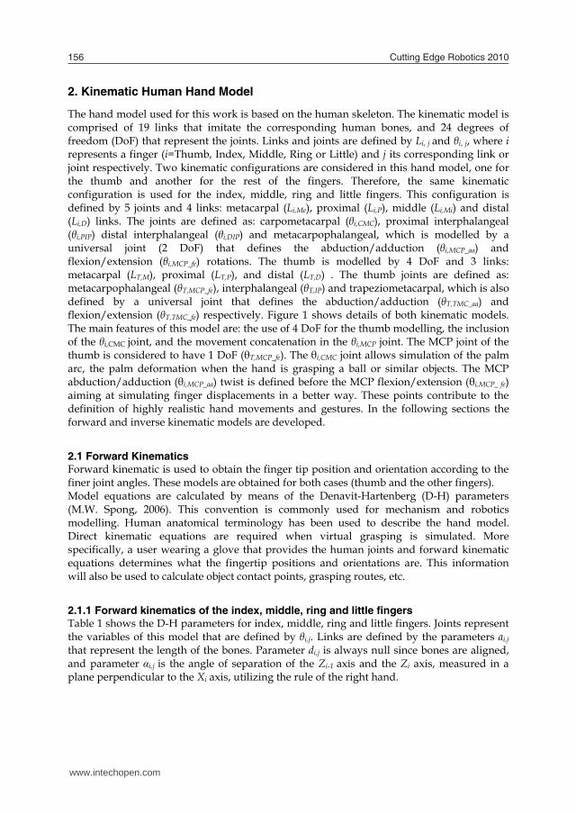
The hand model used for this work is based on the human skeleton. The kinematic model is comprised of 19 links that imitate the corresponding human bones, and 24 degrees of freedom (DoF) that represent the joints. Links and joints are defined by Li, j and θi, j, where i represents a finger (i=Thumb, Index, Middle, Ring or Little) and j its corresponding link or joint respectively. Two kinematic configurations are considered in this hand model, one for the thumb and another for the rest of the fingers. Therefore, the same kinematic configuration is used for the index, middle, ring and little fingers. This configuration is defined by 5 joints and 4 links: metacarpal (Li,Me), proximal (Li,P), middle (Li,Mi) and distal (Li,D) links. The joints are defined as: carpometacarpal (θi,CMC), proximal interphalangeal (θi,PIP) distal interphalangeal (θi,DIP) and metacarpophalangeal, which is modelled by a universal joint (2 DoF) that defines the abduction/adduction (θi,MCP_aa) and flexion/extension (θi,MCP_fe) rotations. The thumb is modelled by 4 DoF and 3 links: metacarpal (LT,M), proximal (LT,P), and distal (LT,D) . The thumb joints are defined as: metacarpophalangeal (θT,MCP_fe), interphalangeal (θT,IP) and trapeziometacarpal, which is also defined by a universal joint that defines the abduction/adduction (θT,TMC_aa) and flexion/extension (θT,TMC_fe) respectively. Figure 1 shows details of both kinematic models. The main features of this model are: the use of 4 DoF for the thumb modelling, the inclusion of the θi,CMC joint, and the movement concatenation in the θi,MCP joint. The MCP joint of the thumb is considered to have 1 DoF (θT,MCP_fe). The θi,CMC joint allows simulation of the palm arc, the palm deformation when the hand is grasping a ball or similar objects. The MCP abduction/adduction (θi,MCP_aa) twist is defined before the MCP flexion/extension (θi,MCP_ fe) aiming at simulating finger displacements in a better way. These points contribute to the definition of highly realistic hand movements and gestures. In the following sections the forward and inverse kinematic models are developed.
2.1 Forward Kinematics Forward kinematic is used to obtain the finger tip position and orientation according to the finer joint angles. These models are obtained for both cases (thumb and the other fingers). Model equations are calculated by means of the Denavit-Hartenberg (D-H) parameters (M.W. Spong, 2006). This convention is commonly used for mechanism and robotics modelling. Human anatomical terminology has been used to describe the hand model. Direct kinematic equations are required when virtual grasping is simulated. More specifically, a user wearing a glove that provides the human joints and forward kinematic equations determines what the fingertip positions and orientations are. This information will also be used to calculate object contact points, grasping routes, etc.
2.1.1 Forward kinematics of the index, middle, ring and little fingers Table 1 shows the D-H parameters for index, middle, ring and little fingers. Joints represent the variables of this model that are defined by θi,j. Links are defined by the parameters ai,j that represent the length of the bones. Parameter di,j is always null since bones are aligned, and parameter αi,j is the angle of separation of the Zi-1 axis and the Zi axis, measured in a plane perpendicular to the Xi axis, utilizing the rule of the right hand.
a) b) Fig. 1. Kinematic configuration of the human hand with 19 links and 24 DoF. Thumb is defined by 3 links (LT,M, LT,P and LT,D) and 4 DoF (θT,TMC_aa, θT,TMC_fe, θT,MCP_fe and θT,IP) whereas index, middle, ring and little fingers are defined by 4 links (Li,Me, Li,P, Li,Mi and Li,D) and 5 DoF (θi,CMC, θi,MCP_aa, θi,MCP_fe, θi,PIP and θi,DIP).
Joint θi,j di,j ai,j αi,j 1 θi,CMC 0 Li,Me π/2 2 θi,MCP aa 0 0 -π/2 3 θi,MCP fe 0 Li,P 0 4 θi,PIP 0 Li,Mi 0 5 θi,DIP 0 Li,D 0
Table 1. D-H parameters for index, middle, ring and little fingers. The forward kinematics of these fingers is shown in equation 1, which is defined according to the parameters of Table 1.
)()()()()()()()( ,45,
34_,
23_,
12,
01
10,
05
10 DIPiiPIPiifeMCPiiaaMCPiiCMCiiiijiiiii TTTTTuTTuTp (1)
Where terms in this equation are: pi represents a matrix that contains position and orientation of the i-finger tip with respect to the center of the wrist, ui represents the vector
www.intechopen.com
SimpliiedHumanHandModelsforManipulationTasks 157
2. Kinematic Human Hand Model
The hand model used for this work is based on the human skeleton. The kinematic model is comprised of 19 links that imitate the corresponding human bones, and 24 degrees of freedom (DoF) that represent the joints. Links and joints are defined by Li, j and θi, j, where i represents a finger (i=Thumb, Index, Middle, Ring or Little) and j its corresponding link or joint respectively. Two kinematic configurations are considered in this hand model, one for the thumb and another for the rest of the fingers. Therefore, the same kinematic configuration is used for the index, middle, ring and little fingers. This configuration is defined by 5 joints and 4 links: metacarpal (Li,Me), proximal (Li,P), middle (Li,Mi) and distal (Li,D) links. The joints are defined as: carpometacarpal (θi,CMC), proximal interphalangeal (θi,PIP) distal interphalangeal (θi,DIP) and metacarpophalangeal, which is modelled by a universal joint (2 DoF) that defines the abduction/adduction (θi,MCP_aa) and flexion/extension (θi,MCP_fe) rotations. The thumb is modelled by 4 DoF and 3 links: metacarpal (LT,M), proximal (LT,P), and distal (LT,D) . The thumb joints are defined as: metacarpophalangeal (θT,MCP_fe), interphalangeal (θT,IP) and trapeziometacarpal, which is also defined by a universal joint that defines the abduction/adduction (θT,TMC_aa) and flexion/extension (θT,TMC_fe) respectively. Figure 1 shows details of both kinematic models. The main features of this model are: the use of 4 DoF for the thumb modelling, the inclusion of the θi,CMC joint, and the movement concatenation in the θi,MCP joint. The MCP joint of the thumb is considered to have 1 DoF (θT,MCP_fe). The θi,CMC joint allows simulation of the palm arc, the palm deformation when the hand is grasping a ball or similar objects. The MCP abduction/adduction (θi,MCP_aa) twist is defined before the MCP flexion/extension (θi,MCP_ fe) aiming at simulating finger displacements in a better way. These points contribute to the definition of highly realistic hand movements and gestures. In the following sections the forward and inverse kinematic models are developed.
2.1 Forward Kinematics Forward kinematic is used to obtain the finger tip position and orientation according to the finer joint angles. These models are obtained for both cases (thumb and the other fingers). Model equations are calculated by means of the Denavit-Hartenberg (D-H) parameters (M.W. Spong, 2006). This convention is commonly used for mechanism and robotics modelling. Human anatomical terminology has been used to describe the hand model. Direct kinematic equations are required when virtual grasping is simulated. More specifically, a user wearing a glove that provides the human joints and forward kinematic equations determines what the fingertip positions and orientations are. This information will also be used to calculate object contact points, grasping routes, etc.
2.1.1 Forward kinematics of the index, middle, ring and little fingers Table 1 shows the D-H parameters for index, middle, ring and little fingers. Joints represent the variables of this model that are defined by θi,j. Links are defined by the parameters ai,j that represent the length of the bones. Parameter di,j is always null since bones are aligned, and parameter αi,j is the angle of separation of the Zi-1 axis and the Zi axis, measured in a plane perpendicular to the Xi axis, utilizing the rule of the right hand.
a) b) Fig. 1. Kinematic configuration of the human hand with 19 links and 24 DoF. Thumb is defined by 3 links (LT,M, LT,P and LT,D) and 4 DoF (θT,TMC_aa, θT,TMC_fe, θT,MCP_fe and θT,IP) whereas index, middle, ring and little fingers are defined by 4 links (Li,Me, Li,P, Li,Mi and Li,D) and 5 DoF (θi,CMC, θi,MCP_aa, θi,MCP_fe, θi,PIP and θi,DIP).
Joint θi,j di,j ai,j αi,j 1 θi,CMC 0 Li,Me π/2 2 θi,MCP aa 0 0 -π/2 3 θi,MCP fe 0 Li,P 0 4 θi,PIP 0 Li,Mi 0 5 θi,DIP 0 Li,D 0
Table 1. D-H parameters for index, middle, ring and little fingers. The forward kinematics of these fingers is shown in equation 1, which is defined according to the parameters of Table 1.
)()()()()()()()( ,45,
34_,
23_,
12,
01
10,
05
10 DIPiiPIPiifeMCPiiaaMCPiiCMCiiiijiiiii TTTTTuTTuTp (1)
Where terms in this equation are: pi represents a matrix that contains position and orientation of the i-finger tip with respect to the center of the wrist, ui represents the vector
www.intechopen.com

CuttingEdgeRobotics2010158
between the center of wrist and the corresponding i-finger reference frame, )( ,05 jiiT is a
matrix that contains the homogeneous matrix between the i-finger reference frame and its corresponding i-finger tip. This matrix consists of the concatenation of matrixes that represent the contribution of each i-finger joint displacement (θi,CMC, θi,MCP aa, θi,MCP fe, θi,PIP,
θi,DIP) the translation and rotation contribution of each joint is defined by the matrix )( ,
1jii
jjT .
10000)cos()sin(0
)sin()cos()sin()cos()cos()sin()cos()sin()sin()sin()cos()cos(
)(,,
,,,,,,,
,,,,,,,
,1
jiji
jijijijijijiji
jijijijijijiji
jiijj
aa
T
(2)
2.1.2 Homogeneous matrixes for the index, middle, ring and little fingers. In order to simplify the equations, some variables are replaced (VR) for the corresponding variable showed in table 2.
θi,j VR ai,j VR Link θi,CMC θ5 Li,Me L4 Metacarpal θi,MCP aa θ6 0 0 θi,MCP fe θ7 Li,P L5 Proximal θi,PIP θ8 Li,Mi L6 Middle θi,DIP θ9 Li,D L7 Distal
Table 2.
sincos
sc
10000010
00
)( ,,,,
,,,,
,10 CMCiMeiCMCiCMCi
CMCiMeiCMCiCMCi
CMCi
sLcscLsc
T
(3)
100000100000
)( _,_,
_,_,
_,21 aaMCPiaaMCPi
aaMCPiaaMCPi
aaMCPi
cssc
T
(4)
10000100
00
)( _,,_,_,
_,,_,_,
_,32 feMCPipifeMCPifeMCPi
feMCPipifeMCPifeMCPi
feMCPi
sLcscLsc
T
(5)
10000100
00
)( ,,,,
,,,,
,43 PIPiMiiPIPiPIPi
PIPiMiiPIPiPIPi
PIPi
sLcscLsc
T
(6)
10000100
00
)( ,,,,
,,,,
,54 DIPiDiDIPiDIPi
DIPiDiDIPiDIPi
DIPi
sLcscLsc
T
(7)
1000100010001
)(,
,
,
01
zi
yi
xi
i uuu
uT (8)
10002222
2222
2222
50
zzzz
yyyy
xxxx
PasnPasnPasn
T (9)
Where:
987576587576598757658757652 )s)ccs-sc(-c+)sss-cc(-(c)c)scs-sc(-c+)css-cc(c( xn (10)
987576587576598757658757652 )s)ccc+sc(-s+)ssc+cc(-(s)c)scc+sc(-s+)csc+cc((s yn (11)
987687698768762 )scss+sc(s+)csss+cc(-szn (12)
987576587576598757658757652 )c)ccs-sc(-c+)sss-cc(-(c+)s)scs-sc(-c+)css-cc-((cxs (13)
987576587576598757658757652 )c)ccc+sc(-s+)ssc+cc(-(s+)s)scc+sc(-s+)csc+cc-((sys (14)
987687698768762 )ccss+sc(s+)ssss+cc-(-szs (15)
www.intechopen.com
SimpliiedHumanHandModelsforManipulationTasks 159
between the center of wrist and the corresponding i-finger reference frame, )( ,05 jiiT is a
matrix that contains the homogeneous matrix between the i-finger reference frame and its corresponding i-finger tip. This matrix consists of the concatenation of matrixes that represent the contribution of each i-finger joint displacement (θi,CMC, θi,MCP aa, θi,MCP fe, θi,PIP,
θi,DIP) the translation and rotation contribution of each joint is defined by the matrix )( ,
1jii
jjT .
10000)cos()sin(0
)sin()cos()sin()cos()cos()sin()cos()sin()sin()sin()cos()cos(
)(,,
,,,,,,,
,,,,,,,
,1
jiji
jijijijijijiji
jijijijijijiji
jiijj
aa
T
(2)
2.1.2 Homogeneous matrixes for the index, middle, ring and little fingers. In order to simplify the equations, some variables are replaced (VR) for the corresponding variable showed in table 2.
θi,j VR ai,j VR Link θi,CMC θ5 Li,Me L4 Metacarpal θi,MCP aa θ6 0 0 θi,MCP fe θ7 Li,P L5 Proximal θi,PIP θ8 Li,Mi L6 Middle θi,DIP θ9 Li,D L7 Distal
Table 2.
sincos
sc
10000010
00
)( ,,,,
,,,,
,10 CMCiMeiCMCiCMCi
CMCiMeiCMCiCMCi
CMCi
sLcscLsc
T
(3)
100000100000
)( _,_,
_,_,
_,21 aaMCPiaaMCPi
aaMCPiaaMCPi
aaMCPi
cssc
T
(4)
10000100
00
)( _,,_,_,
_,,_,_,
_,32 feMCPipifeMCPifeMCPi
feMCPipifeMCPifeMCPi
feMCPi
sLcscLsc
T
(5)
10000100
00
)( ,,,,
,,,,
,43 PIPiMiiPIPiPIPi
PIPiMiiPIPiPIPi
PIPi
sLcscLsc
T
(6)
10000100
00
)( ,,,,
,,,,
,54 DIPiDiDIPiDIPi
DIPiDiDIPiDIPi
DIPi
sLcscLsc
T
(7)
1000100010001
)(,
,
,
01
zi
yi
xi
i uuu
uT (8)
10002222
2222
2222
50
zzzz
yyyy
xxxx
PasnPasnPasn
T (9)
Where:
987576587576598757658757652 )s)ccs-sc(-c+)sss-cc(-(c)c)scs-sc(-c+)css-cc(c( xn (10)
987576587576598757658757652 )s)ccc+sc(-s+)ssc+cc(-(s)c)scc+sc(-s+)csc+cc((s yn (11)
987687698768762 )scss+sc(s+)csss+cc(-szn (12)
987576587576598757658757652 )c)ccs-sc(-c+)sss-cc(-(c+)s)scs-sc(-c+)css-cc-((cxs (13)
987576587576598757658757652 )c)ccc+sc(-s+)ssc+cc(-(s+)s)scc+sc(-s+)csc+cc-((sys (14)
987687698768762 )ccss+sc(s+)ssss+cc-(-szs (15)
www.intechopen.com

CuttingEdgeRobotics2010160
652 scxa (16)
652 ssya (17)
62 cza (18)
62 cza (19)
4557576568757656875765
79875765875765798757658757652
Lc+)Lss-cc(c+L)scs-sc(-c+L)css-cc(c+L)s)ccs-sc(-c+)sss-cc(-(c+L)c)scs-sc(-c+)css-cc((cxP (20)
4557576568757656875765
79875765875765798757658757652
Ls+)Lsc+cc(s+L)scc+sc(-s+L)csc+cc(s+
L)s)ccc+sc(-s+)ssc+cc(-(s+L)c)scc+sc(-s+)csc+cc((syP (21)
576687687679876876798768762 Lcs-)Lssscc(s-L)scsssc(sL)cssscc(-s zP (22)
2.1.3 Forward kinematics of the thumb Forward kinematics of the thumb is defined in a similar way. Table 3 shows the D-H parameters of the thumb.
Joint θT,j dT,j aT,j αT,j 1 θT,TMC aa 0 0 π/2 2 θT,TMC fe 0 LT,M 0 3 θT,MCP fe 0 LT,P 0 4 θT,IP 0 LT,D 0
Table 3. D-H Parameters for the Thumb Equation 23 represents the direct kinematics for the thumb as follows:
)()()()()()()( ,34_,
23_,
12_,
01
10,
04
10 IPTTfeMCPTTfeTMCTTaaTMCTTTTjTTTTT TTTTuTTuTp (23)
Where terms in this equation are: PT represents a matrix that contains position and orientation of the thumb finger tip with respect to the center of the wrist, uT represents the vector between the center of wrist and the corresponding thumb reference frame, )( ,
04 jTiT is a matrix that contains the homogeneous
matrix between the thumb reference frame and its finger tip. This matrix is also a concatenation of the corresponding matrixes; which are obtained by the thumb joints (θT,TMC_ aa, θT,TMC_ fe, θT,MCP fe, θT,IP).
2.1.4 Homogeneous matrixes for the Thumb model In order to simplify the equations, some variables are replaced (VR) for the corresponding variable showed in table 2.
θT,j VR aT,j VR Link θT,TMC aa θ1 0 0 θT,TMC fe θ2 LT,M L1 Metacarpal θT,MCP fe θ3 LT,P L2 Proximal θT,IP θ4 LT,D L3 Distal
Table 4.
sincos
sc
100000100000
)( _,_,
_,_,
_,10 aaTMCTaaTMCT
aaTMCTaaTMCT
aaTMCT
cssc
T
(24)
10000100
00
)( _,,_,_,
_,,_,_,
_,21 feTMCTMTfeTMCTfeTMCT
feTMCTMTfeTMCTfeTMCT
feTMCT
sLcscLsc
T
(25)
10000100
00
)( ,,,,
,,,,
,32 MCPTPTMCPTMCPT
MCPTPTMCPTMCPT
MCPT
sLcscLsc
T
(26)
10000100
00
)( ,,,,
,,,,
,43 IPTDTIPTIPT
IPTDTIPTIPT
IPT
sLcscLsc
T
(27)
1000100010001
)(,
,
,
01
zT
yT
xT
Thumb uuu
uT (28)
www.intechopen.com
SimpliiedHumanHandModelsforManipulationTasks 161
652 scxa (16)
652 ssya (17)
62 cza (18)
62 cza (19)
4557576568757656875765
79875765875765798757658757652
Lc+)Lss-cc(c+L)scs-sc(-c+L)css-cc(c+L)s)ccs-sc(-c+)sss-cc(-(c+L)c)scs-sc(-c+)css-cc((cxP (20)
4557576568757656875765
79875765875765798757658757652
Ls+)Lsc+cc(s+L)scc+sc(-s+L)csc+cc(s+
L)s)ccc+sc(-s+)ssc+cc(-(s+L)c)scc+sc(-s+)csc+cc((syP (21)
576687687679876876798768762 Lcs-)Lssscc(s-L)scsssc(sL)cssscc(-s zP (22)
2.1.3 Forward kinematics of the thumb Forward kinematics of the thumb is defined in a similar way. Table 3 shows the D-H parameters of the thumb.
Joint θT,j dT,j aT,j αT,j 1 θT,TMC aa 0 0 π/2 2 θT,TMC fe 0 LT,M 0 3 θT,MCP fe 0 LT,P 0 4 θT,IP 0 LT,D 0
Table 3. D-H Parameters for the Thumb Equation 23 represents the direct kinematics for the thumb as follows:
)()()()()()()( ,34_,
23_,
12_,
01
10,
04
10 IPTTfeMCPTTfeTMCTTaaTMCTTTTjTTTTT TTTTuTTuTp (23)
Where terms in this equation are: PT represents a matrix that contains position and orientation of the thumb finger tip with respect to the center of the wrist, uT represents the vector between the center of wrist and the corresponding thumb reference frame, )( ,
04 jTiT is a matrix that contains the homogeneous
matrix between the thumb reference frame and its finger tip. This matrix is also a concatenation of the corresponding matrixes; which are obtained by the thumb joints (θT,TMC_ aa, θT,TMC_ fe, θT,MCP fe, θT,IP).
2.1.4 Homogeneous matrixes for the Thumb model In order to simplify the equations, some variables are replaced (VR) for the corresponding variable showed in table 2.
θT,j VR aT,j VR Link θT,TMC aa θ1 0 0 θT,TMC fe θ2 LT,M L1 Metacarpal θT,MCP fe θ3 LT,P L2 Proximal θT,IP θ4 LT,D L3 Distal
Table 4.
sincos
sc
100000100000
)( _,_,
_,_,
_,10 aaTMCTaaTMCT
aaTMCTaaTMCT
aaTMCT
cssc
T
(24)
10000100
00
)( _,,_,_,
_,,_,_,
_,21 feTMCTMTfeTMCTfeTMCT
feTMCTMTfeTMCTfeTMCT
feTMCT
sLcscLsc
T
(25)
10000100
00
)( ,,,,
,,,,
,32 MCPTPTMCPTMCPT
MCPTPTMCPTMCPT
MCPT
sLcscLsc
T
(26)
10000100
00
)( ,,,,
,,,,
,43 IPTDTIPTIPT
IPTDTIPTIPT
IPT
sLcscLsc
T
(27)
1000100010001
)(,
,
,
01
zT
yT
xT
Thumb uuu
uT (28)
www.intechopen.com
CuttingEdgeRobotics2010162
10001111
1111
1111
40
zzzz
yyyy
xxxx
PasnPasnPasn
T (29)
Where:
432132143213211 )scsc-sc(-c+)cssc-cc(cxn (30)
432132143213211 )scss-sc(-s+)csss-cc(syn (31)
43232432321 )scc+s(-s+)csc+c(szn (32)
432132143213211 )ccsc-sc(-c+)sssc-cc-(cxs (33)
432132143213211 )ccss-sc(-s+)ssss-cc-(sys (34)
43232432321 )ccc+s(-s+)ssc+c-(szs (35)
11 sa x (36)
11 ca y (37)
01 za (38)
121232132134321321343213211 Lcc+)Lssc-cc(c+L)scsc-sc(-c+L)cssc-cc(cxP
(39)
121232132134321321343213211 Lcs+)Lsss-cc(s+L)scss-sc(-s+L)csss-cc(syP (40)
12232323432323432321 Ls+)Lsc+c(s+L)scc+s(-s+L)csc+c(szP (41)
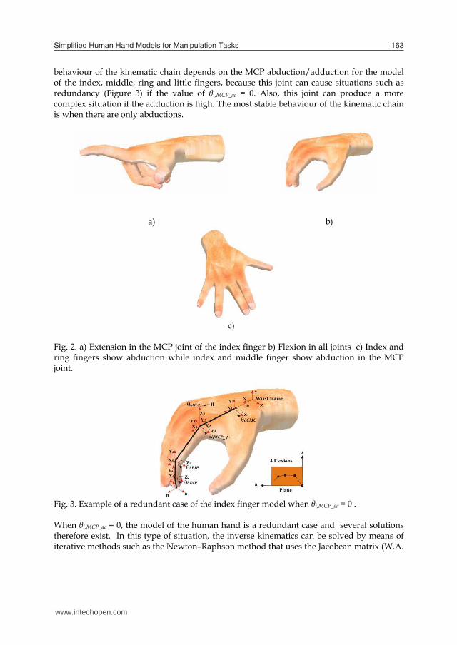
2.2 Inverse Kinematics The model of the two finger types described in the forward kinematics section can generate a combination of movement with flexions, extensions, abductions, adductions and redundant cases. Figure 2 shows examples of flexion, extension and abductions. The solution of the inverse kinematics can be derived from geometric methods (J.M. Selig, 2005), such as the relation of triangles. The hand can reproduce positive or negative movements with regard to a reference line for some joints. The movements of the fingers that can be in two different quadrants are: flexion/extension and abduction/adduction. The inverse kinematics is solved in all these cases of movement. In addition, the kinematic
behaviour of the kinematic chain depends on the MCP abduction/adduction for the model of the index, middle, ring and little fingers, because this joint can cause situations such as redundancy (Figure 3) if the value of θi,MCP_aa = 0. Also, this joint can produce a more complex situation if the adduction is high. The most stable behaviour of the kinematic chain is when there are only abductions.
a) b)
c)
Fig. 2. a) Extension in the MCP joint of the index finger b) Flexion in all joints c) Index and ring fingers show abduction while index and middle finger show abduction in the MCP joint.
Fig. 3. Example of a redundant case of the index finger model when θi,MCP_aa = 0 . When θi,MCP_aa = 0, the model of the human hand is a redundant case and several solutions therefore exist. In this type of situation, the inverse kinematics can be solved by means of iterative methods such as the Newton–Raphson method that uses the Jacobean matrix (W.A.
www.intechopen.com
SimpliiedHumanHandModelsforManipulationTasks 163
10001111
1111
1111
40
zzzz
yyyy
xxxx
PasnPasnPasn
T (29)
Where:
432132143213211 )scsc-sc(-c+)cssc-cc(cxn (30)
432132143213211 )scss-sc(-s+)csss-cc(syn (31)
43232432321 )scc+s(-s+)csc+c(szn (32)
432132143213211 )ccsc-sc(-c+)sssc-cc-(cxs (33)
432132143213211 )ccss-sc(-s+)ssss-cc-(sys (34)
43232432321 )ccc+s(-s+)ssc+c-(szs (35)
11 sa x (36)
11 ca y (37)
01 za (38)
121232132134321321343213211 Lcc+)Lssc-cc(c+L)scsc-sc(-c+L)cssc-cc(cxP
(39)
121232132134321321343213211 Lcs+)Lsss-cc(s+L)scss-sc(-s+L)csss-cc(syP (40)
12232323432323432321 Ls+)Lsc+c(s+L)scc+s(-s+L)csc+c(szP (41)
2.2 Inverse Kinematics The model of the two finger types described in the forward kinematics section can generate a combination of movement with flexions, extensions, abductions, adductions and redundant cases. Figure 2 shows examples of flexion, extension and abductions. The solution of the inverse kinematics can be derived from geometric methods (J.M. Selig, 2005), such as the relation of triangles. The hand can reproduce positive or negative movements with regard to a reference line for some joints. The movements of the fingers that can be in two different quadrants are: flexion/extension and abduction/adduction. The inverse kinematics is solved in all these cases of movement. In addition, the kinematic
behaviour of the kinematic chain depends on the MCP abduction/adduction for the model of the index, middle, ring and little fingers, because this joint can cause situations such as redundancy (Figure 3) if the value of θi,MCP_aa = 0. Also, this joint can produce a more complex situation if the adduction is high. The most stable behaviour of the kinematic chain is when there are only abductions.
a) b)
c)
Fig. 2. a) Extension in the MCP joint of the index finger b) Flexion in all joints c) Index and ring fingers show abduction while index and middle finger show abduction in the MCP joint.
Fig. 3. Example of a redundant case of the index finger model when θi,MCP_aa = 0 . When θi,MCP_aa = 0, the model of the human hand is a redundant case and several solutions therefore exist. In this type of situation, the inverse kinematics can be solved by means of iterative methods such as the Newton–Raphson method that uses the Jacobean matrix (W.A.
www.intechopen.com
CuttingEdgeRobotics2010164
Wolovich & H. Elliot, 1984) and (A. Balestino et al., 1984). To solve this redundant case correctly, constraints have been implemented to solve with a convergent solution.
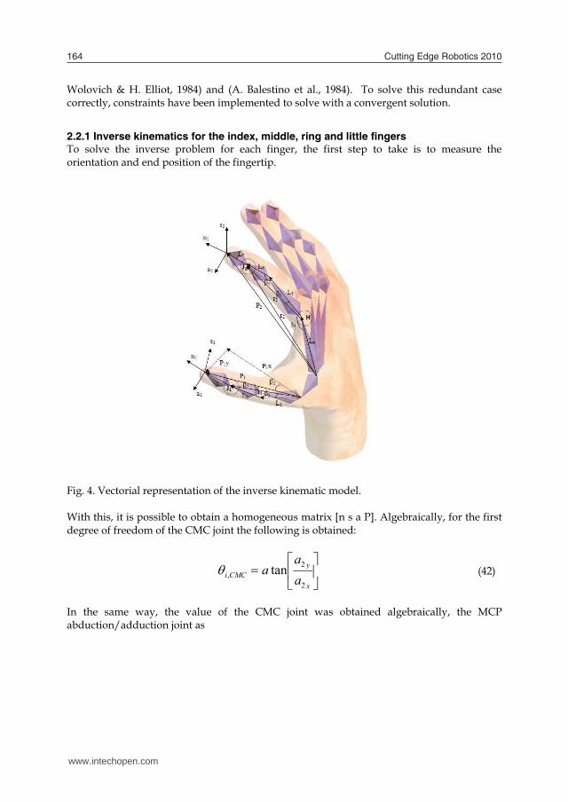
2.2.1 Inverse kinematics for the index, middle, ring and little fingers To solve the inverse problem for each finger, the first step to take is to measure the orientation and end position of the fingertip.
Fig. 4. Vectorial representation of the inverse kinematic model.
With this, it is possible to obtain a homogeneous matrix [n s a P]. Algebraically, for the first degree of freedom of the CMC joint the following is obtained:
x
yCMCi a
aa
2
2, tan
(42)
In the same way, the value of the CMC joint was obtained algebraically, the MCP abduction/adduction joint as
z
CMCi
x
aaMCPi a
a
a2
,
2
_,
)cos(tan
(43)
Dependency exists among the following joints: flexions for MCP_ fe, PIP and DIP. They are solved by means of geometric methods. With vector P2 it is possible to obtain a point J2 with the following expression:
]*[ 2722 nLPJ (44) Another vector H is calculated with the CMC information and length L4 of the metacarpal link such as:
)cos( ,4 CMCix LH )sin( ,4 CMCiy LH
0zH T
zyx HHHH ][
(45)
With information J2 and H it is possible to obtain the vectors u, r2 and r3 as shown in Figure 4.
HJu 2 (46)
)( 22 Jnormr
(47)
)(3 unormr
(48)
With vectors u, r2, r3 and lengths L4, L5, L6 and using the law of cosines the angles β4, β5 and β6 are obtained.
34
22
23
24
4 2cos
rLrrLa
(49)
35
26
23
25
5 2cos
rLLrLa
(50)
56
23
25
26
6 2cos
LLrLLa
(51)
www.intechopen.com
SimpliiedHumanHandModelsforManipulationTasks 165
Wolovich & H. Elliot, 1984) and (A. Balestino et al., 1984). To solve this redundant case correctly, constraints have been implemented to solve with a convergent solution.
2.2.1 Inverse kinematics for the index, middle, ring and little fingers To solve the inverse problem for each finger, the first step to take is to measure the orientation and end position of the fingertip.
Fig. 4. Vectorial representation of the inverse kinematic model.
With this, it is possible to obtain a homogeneous matrix [n s a P]. Algebraically, for the first degree of freedom of the CMC joint the following is obtained:
x
yCMCi a
aa
2
2, tan
(42)
In the same way, the value of the CMC joint was obtained algebraically, the MCP abduction/adduction joint as
z
CMCi
x
aaMCPi a
a
a2
,
2
_,
)cos(tan
(43)
Dependency exists among the following joints: flexions for MCP_ fe, PIP and DIP. They are solved by means of geometric methods. With vector P2 it is possible to obtain a point J2 with the following expression:
]*[ 2722 nLPJ (44) Another vector H is calculated with the CMC information and length L4 of the metacarpal link such as:
)cos( ,4 CMCix LH )sin( ,4 CMCiy LH
0zH T
zyx HHHH ][
(45)
With information J2 and H it is possible to obtain the vectors u, r2 and r3 as shown in Figure 4.
HJu 2 (46)
)( 22 Jnormr
(47)
)(3 unormr
(48)
With vectors u, r2, r3 and lengths L4, L5, L6 and using the law of cosines the angles β4, β5 and β6 are obtained.
34
22
23
24
4 2cos
rLrrLa
(49)
35
26
23
25
5 2cos
rLLrLa
(50)
56
23
25
26
6 2cos
LLrLLa
(51)
www.intechopen.com
CuttingEdgeRobotics2010166
MCP flexion/extension is obtained as:
45_, feMCPi (52)
The extension & hyperextension for the MCP joint is obtained as:
54_, hypMCPi (53)
The PIP joint is obtained as:
6, PIPi (54)
Finally, the DIP joint is obtained by the algebraic method.
z23434
y13431423141342
x134314231413421
)n)scc-s(s
+)nccs+sssc-scc+scc(c+)nscs-scsc-ssc-ccc(ck
(55)
z23434
y13432143143124
x134321431431242
)n)scs+s(c
+)nccc+scsc-scs-csc(-s+)nscc-sccc-sss+ccc(-sk
(56)
]k,atan2[k 12, DIPi (57)
2.2.2 Inverse kinematics of the thumb For the thumb the inverse kinematic is obtained by means of algebraic method. TMC_aa is obtained as:
x
yaaTMCT P
Pa
1
1_, tan (58)
J1 and vectors r1, x1 and x2 are obtained as:
][ 1311 nLPJ )( 11 Jnormr
21
22
211
1 2 LLLLrx
(59)
212 1 xx
MCP is obtained as:
],[2tan 12, xxaMCPT (60) Auxiliary variables are calculated such as:
))(( 1213 xLLx 224 xLx
21
21 yxxy JJJ
24
23
3415 xx
xJxJx xyz
24
23
4316 xx
xJxJx xyz
(61)
TMC_fe is obtained as:
],[2tan 56_, xxafeTMCT (62)
],[2tan 21
211 yxz nnna
(63)
Finally, IP is obtained as:
MCPTfeTMCTIPT ,_,, (64)
3. Main Constraints of Finger Movements
Joint finger movements are limited to a specific range because of static constraints, intra-finger constraints and inter-finger constraints. Intra-finger and inter-finger constraints are often called kinematic constraints, and these are the ones responsible for producing natural movements both statically and kynematically. However, this range of movement is somewhat ambiguous because the range depends on various factors involving human hand biomechanics.
3.1 Inter-finger constraints This type of constraint refers to some dependency among fingers while they are in motion (J. Lin et al., 2000). The inter-finger constraints were obtained by using the hand model and Cyberglove. These types of constraints are coupled movements among the index, middle,
www.intechopen.com
SimpliiedHumanHandModelsforManipulationTasks 167
MCP flexion/extension is obtained as:
45_, feMCPi (52)
The extension & hyperextension for the MCP joint is obtained as:
54_, hypMCPi (53)
The PIP joint is obtained as:
6, PIPi (54)
Finally, the DIP joint is obtained by the algebraic method.
z23434
y13431423141342
x134314231413421
)n)scc-s(s
+)nccs+sssc-scc+scc(c+)nscs-scsc-ssc-ccc(ck
(55)
z23434
y13432143143124
x134321431431242
)n)scs+s(c
+)nccc+scsc-scs-csc(-s+)nscc-sccc-sss+ccc(-sk
(56)
]k,atan2[k 12, DIPi (57)
2.2.2 Inverse kinematics of the thumb For the thumb the inverse kinematic is obtained by means of algebraic method. TMC_aa is obtained as:
x
yaaTMCT P
Pa
1
1_, tan (58)
J1 and vectors r1, x1 and x2 are obtained as:
][ 1311 nLPJ )( 11 Jnormr
21
22
211
1 2 LLLLrx
(59)
212 1 xx
MCP is obtained as:
],[2tan 12, xxaMCPT (60) Auxiliary variables are calculated such as:
))(( 1213 xLLx 224 xLx
21
21 yxxy JJJ
24
23
3415 xx
xJxJx xyz
24
23
4316 xx
xJxJx xyz
(61)
TMC_fe is obtained as:
],[2tan 56_, xxafeTMCT (62)
],[2tan 21
211 yxz nnna
(63)
Finally, IP is obtained as:
MCPTfeTMCTIPT ,_,, (64)
3. Main Constraints of Finger Movements
Joint finger movements are limited to a specific range because of static constraints, intra-finger constraints and inter-finger constraints. Intra-finger and inter-finger constraints are often called kinematic constraints, and these are the ones responsible for producing natural movements both statically and kynematically. However, this range of movement is somewhat ambiguous because the range depends on various factors involving human hand biomechanics.
3.1 Inter-finger constraints This type of constraint refers to some dependency among fingers while they are in motion (J. Lin et al., 2000). The inter-finger constraints were obtained by using the hand model and Cyberglove. These types of constraints are coupled movements among the index, middle,
www.intechopen.com
CuttingEdgeRobotics2010168
ring and little fingers. The relationship among angles with the middle, ring and little fingers has been measured to represent real movements of the hand model. Middle, ring and little fingers share common flexor tendons. It implies involuntary movements due to this strong coupling. These cases are defined by: - Flexion in the ring finger θR,MCP_fe due to a flexion in the middle finger and no flexions of
the index and little fingers. When this unique flexion is generated, the flexion of the ring finger is equal to a percentage of the middle finger flexion, as described in equation (65).
feMCPMfeMCPR _,_, 32 (65)
- Flexion in the ring finger θR,MCP_fe is produced when there is flexion solely in the little
finger. It is described in equation (66). A small flexion is also produced in the middle when flexion in the little is high.
feMCPLfeMCPR _,_, 127 (66)
- Flexion of middle and little fingers θM,MCP_fe, θL,MCP_fe are produced when there is flexion
solely in the ring finger. Involuntary flexions are similar and proportional to the ring flexion as described in equation (67) and (68).
º60_,_, feMCPMfeMCPR (67)
º50_,_, feMCPLfeMCPR (68) - Ring and little abduction/adductions are similar. In most cases is very difficult to change
the abduction of a finger without changes in the other. Equation (69) represents this constraint.
aaMCPLaaMCPR _,_, (69) - Finally, another involuntary movement appears in the middle flexion when a unique
flexion is done in the index finger. This relation is described in equation (70).
feMCPIfeMCPM _,_, 51 (70)
3.2 Intra-finger constraints Intra-finger constraints refer to the dependency of internal joints. New intra-finger have been obtained according to the hand gesture. Gestures have been classified as prismatic and circular regardless of power or precision grasping (M.R. Cutkosky, 1989). Some experiments have been carried out in order to obtain these intra-finger relations. Circular grasping implies a strong relation among finger joints. The most accepted intra-finger constraint is:
PIPDIP 32 (71)
It has been analyzed by several researchers, such as (C.S. Fahn & H. Sun, 2005) and has been efficiently checked in our experiments. Equations (72) and (73) show two constraints used for index, middle, ring and little fingers in circular grasping.
PIPiDIPi ,, 32 (72)
PIPifeMCPi ,_, 34 (73)
The following equations show intra-finger constraints used for circular grasping:
MCPTfeTMCT ,_, 1011 (74)
IPTMCPT ,, 54 (75)
CMCMCMCI ,, (76)
CMCRCMCM ,, 21 (77)
aaMCPIaaMCPM _,_, 51 (78)
CMCLCMCR ,, 32 (79)
aaMCPLaaMCPR _,_, 21 (80)
)(21
,,, DIPLDIPMDIPR (81)
Also, equations (76), (77), (78), (79) and (80) are used for prismatic trajectories. Equations (82) and (83) show two constraints used for index, middle, ring and little fingers in prismatic grasping.
PIPifeMCPi ,_, 23 (82)
www.intechopen.com
SimpliiedHumanHandModelsforManipulationTasks 169
ring and little fingers. The relationship among angles with the middle, ring and little fingers has been measured to represent real movements of the hand model. Middle, ring and little fingers share common flexor tendons. It implies involuntary movements due to this strong coupling. These cases are defined by: - Flexion in the ring finger θR,MCP_fe due to a flexion in the middle finger and no flexions of
the index and little fingers. When this unique flexion is generated, the flexion of the ring finger is equal to a percentage of the middle finger flexion, as described in equation (65).
feMCPMfeMCPR _,_, 32 (65)
- Flexion in the ring finger θR,MCP_fe is produced when there is flexion solely in the little
finger. It is described in equation (66). A small flexion is also produced in the middle when flexion in the little is high.
feMCPLfeMCPR _,_, 127 (66)
- Flexion of middle and little fingers θM,MCP_fe, θL,MCP_fe are produced when there is flexion
solely in the ring finger. Involuntary flexions are similar and proportional to the ring flexion as described in equation (67) and (68).
º60_,_, feMCPMfeMCPR (67)
º50_,_, feMCPLfeMCPR (68) - Ring and little abduction/adductions are similar. In most cases is very difficult to change
the abduction of a finger without changes in the other. Equation (69) represents this constraint.
aaMCPLaaMCPR _,_, (69) - Finally, another involuntary movement appears in the middle flexion when a unique
flexion is done in the index finger. This relation is described in equation (70).
feMCPIfeMCPM _,_, 51 (70)
3.2 Intra-finger constraints Intra-finger constraints refer to the dependency of internal joints. New intra-finger have been obtained according to the hand gesture. Gestures have been classified as prismatic and circular regardless of power or precision grasping (M.R. Cutkosky, 1989). Some experiments have been carried out in order to obtain these intra-finger relations. Circular grasping implies a strong relation among finger joints. The most accepted intra-finger constraint is:
PIPDIP 32 (71)
It has been analyzed by several researchers, such as (C.S. Fahn & H. Sun, 2005) and has been efficiently checked in our experiments. Equations (72) and (73) show two constraints used for index, middle, ring and little fingers in circular grasping.
PIPiDIPi ,, 32 (72)
PIPifeMCPi ,_, 34 (73)
The following equations show intra-finger constraints used for circular grasping:
MCPTfeTMCT ,_, 1011 (74)
IPTMCPT ,, 54 (75)
CMCMCMCI ,, (76)
CMCRCMCM ,, 21 (77)
aaMCPIaaMCPM _,_, 51 (78)
CMCLCMCR ,, 32 (79)
aaMCPLaaMCPR _,_, 21 (80)
)(21
,,, DIPLDIPMDIPR (81)
Also, equations (76), (77), (78), (79) and (80) are used for prismatic trajectories. Equations (82) and (83) show two constraints used for index, middle, ring and little fingers in prismatic grasping.
PIPifeMCPi ,_, 23 (82)
www.intechopen.com
CuttingEdgeRobotics2010170
DIPiPIPi ,, 2 (83) Finally, the following equations show intra-finger constraints for prismatic grasping.
MCPTfeTMCT ,_, 1110 (84)
IPTMCPT ,, 56 (85)
4. Simplified Human Hand Models
This section describes simplified human hand models that properly represent the kinematic behaviour of the human hand in accordance with the precision and application required. The human hand model of 24 DoF is used as a basis for comparison among simplified hand models with fewer degrees of freedom than the 24 DoF of the hand model described in section 2. Kinematic constraints are used in order to obtain simplified hand models, which allow for reducing the number of independent variables or joints in the original model. In other words, with few independent variables is possible to reconstruct a gesture of 24 degrees of freedom with an acceptable error with respect to the original gesture of 24 degrees of freedom not reconstructed. In previous works, two simplified hand models with 6 and 9 DoF have been evaluated in (S. Cobos et al., 2008a) and (S. Cobos et al. 2008b). Simplified human hand models are obtained using dependent and independent variables, theses dependent variables or dependent joints are calculated using kinematic constraints such as are showed in equations (65) to (85). Table 3 shows simplified hand models from 1 to 24 degrees of freedom, and the independent variables used by each simplified hand model. Models 1 to 6 DoF are appropriate for circular power grasps. To control a gesture with one degree of freedom has been demonstrated previously in a robotic hand e.g. The Tuat/Karlsruhe Hand (N. Fukaya et al., 2000) is designed with 24 joints and 1 DoF controlled, this type of device is able to do circular power grasps. In this category the models are capable of performing power grasps with security and stability in the grip without achieving a great precision and skill in handling for precision grasps. Greater precision and dexterity is derived from 9 degrees of freedom, thus is possible to carry out precision grasps. Simplified hand models of 9 to 13 DoF are more precise for both types of grasp: precision and power grasps. Finally, a higher level of realism and sensitivity is achieved with models from 15 to 24 DoF. Table 3, the model from 1 to 9 DoF shows all independent variables that are used. From the model with 10 to 24 DoF uses the same variables from the previous model plus an additional variable e.g. the model with 10 DoF uses the same variables of the model with 9 DoF plus an additional variable. The reduction of elements from 13 to 1 DoF leads to increasingly rely on interpolations and constraints associated with an increased error in the grip trajectory when the dependent variables are obtained. Somehow, this technique depends on optimizing the functionality of a particular inter-finger or intra-finger constraint.
Simplified hands
(Num. DoF)
Independent Joints
1 DIPI ,
2 DIPI , aaTMCT _,
3 DIPI ,
aaTMCT _, IPT ,
4 DIPI ,
aaTMCT _, IPT , aaMCPI _,
5 DIPI ,
aaTMCT _, IPT ,
aaMCPI _, aaMCPL _,
6 DIPI ,
aaTMCT _, IPT ,
aaMCPI _, aaMCPL _, CMCL,
7
DIPI , aaTMCT _,
IPT , aaMCPI _,
aaMCPL _, CMCL,
DIPR,
8 DIPI ,
aaTMCT _, IPT ,
aaMCPI _, aaMCPL _, CMCL,
DIPR,
DIPL,
9 DIPI ,
aaTMCT _, IPT ,
aaMCPI _, aaMCPL _, CMCL,
DIPR,
DIPL,
DIPM ,
10 Simplified hand with 9 DoF +PIPI ,
11 Simplified hand with 10 DoF + PIPR,
12 Simplified hand with 11 DoF + PIPL,
13 Simplified hand with 12 DoF + PIPM ,
14 Simplified hand with 13 DoF + MCPT ,
15 Simplified hand with 14 DoF + MCPI ,
16 Simplified hand with 15 DoF + MCPL,
17 Simplified hand with 16 DoF + MCPR,
18 Simplified hand with 17 DoF + MCPM ,
19 Simplified hand with 18 DoF + aaMCPR _,
20 Simplified hand with 19 DoF + feTMCT _,
21 Simplified hand with 20 DoF + CMCR,
22 Simplified hand with 21 DoF + CMCM ,
23 Simplified hand with 22 DoF + CMCI ,
24 Simplified hand with 23 DoF + aaMCPM _, (Original human hand model)
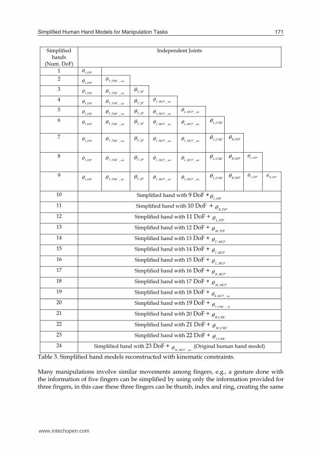
Table 3. Simplified hand models reconstructed with kinematic constraints. Many manipulations involve similar movements among fingers, e.g., a gesture done with the information of five fingers can be simplified by using only the information provided for three fingers, in this case these three fingers can be thumb, index and ring, creating the same
www.intechopen.com
SimpliiedHumanHandModelsforManipulationTasks 171
DIPiPIPi ,, 2 (83) Finally, the following equations show intra-finger constraints for prismatic grasping.
MCPTfeTMCT ,_, 1110 (84)
IPTMCPT ,, 56 (85)
4. Simplified Human Hand Models
This section describes simplified human hand models that properly represent the kinematic behaviour of the human hand in accordance with the precision and application required. The human hand model of 24 DoF is used as a basis for comparison among simplified hand models with fewer degrees of freedom than the 24 DoF of the hand model described in section 2. Kinematic constraints are used in order to obtain simplified hand models, which allow for reducing the number of independent variables or joints in the original model. In other words, with few independent variables is possible to reconstruct a gesture of 24 degrees of freedom with an acceptable error with respect to the original gesture of 24 degrees of freedom not reconstructed. In previous works, two simplified hand models with 6 and 9 DoF have been evaluated in (S. Cobos et al., 2008a) and (S. Cobos et al. 2008b). Simplified human hand models are obtained using dependent and independent variables, theses dependent variables or dependent joints are calculated using kinematic constraints such as are showed in equations (65) to (85). Table 3 shows simplified hand models from 1 to 24 degrees of freedom, and the independent variables used by each simplified hand model. Models 1 to 6 DoF are appropriate for circular power grasps. To control a gesture with one degree of freedom has been demonstrated previously in a robotic hand e.g. The Tuat/Karlsruhe Hand (N. Fukaya et al., 2000) is designed with 24 joints and 1 DoF controlled, this type of device is able to do circular power grasps. In this category the models are capable of performing power grasps with security and stability in the grip without achieving a great precision and skill in handling for precision grasps. Greater precision and dexterity is derived from 9 degrees of freedom, thus is possible to carry out precision grasps. Simplified hand models of 9 to 13 DoF are more precise for both types of grasp: precision and power grasps. Finally, a higher level of realism and sensitivity is achieved with models from 15 to 24 DoF. Table 3, the model from 1 to 9 DoF shows all independent variables that are used. From the model with 10 to 24 DoF uses the same variables from the previous model plus an additional variable e.g. the model with 10 DoF uses the same variables of the model with 9 DoF plus an additional variable. The reduction of elements from 13 to 1 DoF leads to increasingly rely on interpolations and constraints associated with an increased error in the grip trajectory when the dependent variables are obtained. Somehow, this technique depends on optimizing the functionality of a particular inter-finger or intra-finger constraint.
Simplified hands
(Num. DoF)
Independent Joints
1 DIPI ,
2 DIPI , aaTMCT _,
3 DIPI ,
aaTMCT _, IPT ,
4 DIPI ,
aaTMCT _, IPT , aaMCPI _,
5 DIPI ,
aaTMCT _, IPT ,
aaMCPI _, aaMCPL _,
6 DIPI ,
aaTMCT _, IPT ,
aaMCPI _, aaMCPL _, CMCL,
7
DIPI , aaTMCT _,
IPT , aaMCPI _,
aaMCPL _, CMCL,
DIPR,
8 DIPI ,
aaTMCT _, IPT ,
aaMCPI _, aaMCPL _, CMCL,
DIPR,
DIPL,
9 DIPI ,
aaTMCT _, IPT ,
aaMCPI _, aaMCPL _, CMCL,
DIPR,
DIPL,
DIPM ,
10 Simplified hand with 9 DoF +PIPI ,
11 Simplified hand with 10 DoF + PIPR,
12 Simplified hand with 11 DoF + PIPL,
13 Simplified hand with 12 DoF + PIPM ,
14 Simplified hand with 13 DoF + MCPT ,
15 Simplified hand with 14 DoF + MCPI ,
16 Simplified hand with 15 DoF + MCPL,
17 Simplified hand with 16 DoF + MCPR,
18 Simplified hand with 17 DoF + MCPM ,
19 Simplified hand with 18 DoF + aaMCPR _,
20 Simplified hand with 19 DoF + feTMCT _,
21 Simplified hand with 20 DoF + CMCR,
22 Simplified hand with 21 DoF + CMCM ,
23 Simplified hand with 22 DoF + CMCI ,
24 Simplified hand with 23 DoF + aaMCPM _, (Original human hand model)
Table 3. Simplified hand models reconstructed with kinematic constraints. Many manipulations involve similar movements among fingers, e.g., a gesture done with the information of five fingers can be simplified by using only the information provided for three fingers, in this case these three fingers can be thumb, index and ring, creating the same
www.intechopen.com
CuttingEdgeRobotics2010172
movement for the middle finger through the information of the index and the little finger through the information of the ring finger. The simplified hand models should be used depending on the relation between the number of degrees of freedom and the allowed error in the application. The degree of dexterity that can be achieved depends largely on the largest number of independent variables having thumb and index finger inside the SHH. The abduction of the thumb and index fingers are very important because at least one degree of freedom from these fingers are considered as independent variables in all the simplified hand models, thus the flexion of the DIP joint of the index finger is included in all the simplified hand models. The abduction/adduction of the thumb TMC joint is important because with a flexion of the IP joint can produce the opposition of the thumb with the other fingers. It’s from SHH with 4 DoF where the abduction of the MCP joint takes importance because allows better positioning of the finger, not SHH with 3 DoF that contain just a flexion in the index finger. In summary the universal joints of the thumb and index fingers are very important for obtaining simplified hand models because of the information they provide.
4.1 Error of simplified hand models The original posture of the 24 DoF is considered the “ideal posture” or “ideal trajectory” to determine the final position of the fingertip with the use of the forward kinematics; the same forward kinematics is used to obtain the final position with the reconstructed vectors. The relative error (δi) is obtained with the original position (opi) and the reconstructed position (rpi) such as:
%100i
iii rp
oprp (86)
The trajectory is conformed of n positions; thus the average error for each finger is:
n
n
ki
i
1
(87)
Where n is the number of positions and i = Thumb, Index, Middle, Ring, Little. Finally, the reconstruction error is calculated using the following expression.
cerror
n
ki
51
(88)
Where Δc is a parameter of calibration this can vary 1-2% among users according to their hand size.
5. Conclusion
In this chapter, the forward and inverse kinematic models of the human hand with 24 DoF have been presented in detail. Thanks to the kinematic model and with the use of the cyberglove several kinematic constraints were developed for consequently obtained simplified human hand models. This simplified human hand models are useful for diverse applications that require security, stability, sensitivity, dexterity, realism or velocity in calculate kinematic parameters. These simplified human hand models represent a significant reduction in the number of independent variables needed to describe a hand gesture, taking into account the opportunity to perform a specific manipulation with fewer elements to control for applications where control with many degrees of freedom is complex or computationally expensive. Finally, the human hand model with 24 DoF serves for applications that requires a greater realism, sensitivity in handling or description of a human hand gesture.
6. References
I. A. Kapandji. (1970). The Physiology of the Joints, volume 1. E&S Livingstone, Edinburgh and London, 2 editions.
I. A. Kapandji. (1981) The hand. Biomechanics of the thumb. In R. Tubiana (Ed.), pp. 404 – 422, Philadelphia: W. B. Saunders.
K.S. Salisbury and B.Roth. (1983). Kinematics and force analysis of articulated mechanical hands, Journal of Mechanims, Transmissions and Actuation in Design, 105, pp. 35 – 41.
S.C. Jacobsen, E. K. Iversen, D. F. Knutti, R. T. Johnson and K. B. Biggers. (1986). Design of the Utah/MIT Dexterous Hand, In Proc. IEEE International conference on robotics and automation, pp. 1520 – 1532.
T. Okada. (1982). Computer control of multijointed finger system for precise object handling, IEEE Transactions on systems, Man, and Cybernetics, Vol. Smc-12, No. 3, pp. 289 – 299
G. Bekey, R. Tomovic, and I. Zeljkovic. (1990), Control architecture for the Belgrade/usc hand, in T. I. S.T. Venkataraman (ed.), Dexterous Robot Hands, Springer-Verlag.
C. Melchiorri and G. Vassura. (1992). Mechanical and control features of the UB Hand Version II, IEEE-RSJ Int. Conf. on intelligent Robots and Systems, IROS’92, Raleigh, NC,1192
C. Melchiorri and G. Vassura. (1993). Mechanical and Control Issues for Integration of an Arm-Hand Robotic System, in Experimental Robotics II, the 2nd Int. Symposium Raja Chatile and Gerd Hirzinger Eds., Springer Verlag.
J. Butterfass, G. Hirzinger, S. Knoch and H. Liu. (1998). DLR’s Multisensory articulated Part I: Hard- and Software Architecture, in Proc. IEEE International Conference on Robotics and Automation, pp. 2081 – 2086.
J. Butterfass, M. Grebenstein, H. Liu and G. Hirzinger. (2001). DLR-Hand II: Next Generation of a Dextrous Robot Hand, Proc. IEEE Int. Conf. on Robotics and Automation, Seoul, Korea, pp. 109 – 114.
Y. K. Lee and I. Shimoyama. (1999). A skeletal Framework Artificial Hand Actuated by Pneumatic Artificial Muscles, IEEE Int. Conf. On Robotics & Automation, Detroit, Michigan, pp. 926 – 931.
www.intechopen.com
SimpliiedHumanHandModelsforManipulationTasks 173
movement for the middle finger through the information of the index and the little finger through the information of the ring finger. The simplified hand models should be used depending on the relation between the number of degrees of freedom and the allowed error in the application. The degree of dexterity that can be achieved depends largely on the largest number of independent variables having thumb and index finger inside the SHH. The abduction of the thumb and index fingers are very important because at least one degree of freedom from these fingers are considered as independent variables in all the simplified hand models, thus the flexion of the DIP joint of the index finger is included in all the simplified hand models. The abduction/adduction of the thumb TMC joint is important because with a flexion of the IP joint can produce the opposition of the thumb with the other fingers. It’s from SHH with 4 DoF where the abduction of the MCP joint takes importance because allows better positioning of the finger, not SHH with 3 DoF that contain just a flexion in the index finger. In summary the universal joints of the thumb and index fingers are very important for obtaining simplified hand models because of the information they provide.
4.1 Error of simplified hand models The original posture of the 24 DoF is considered the “ideal posture” or “ideal trajectory” to determine the final position of the fingertip with the use of the forward kinematics; the same forward kinematics is used to obtain the final position with the reconstructed vectors. The relative error (δi) is obtained with the original position (opi) and the reconstructed position (rpi) such as:
%100i
iii rp
oprp (86)
The trajectory is conformed of n positions; thus the average error for each finger is:
n
n
ki
i
1
(87)
Where n is the number of positions and i = Thumb, Index, Middle, Ring, Little. Finally, the reconstruction error is calculated using the following expression.
cerror
n
ki
51
(88)
Where Δc is a parameter of calibration this can vary 1-2% among users according to their hand size.
5. Conclusion
In this chapter, the forward and inverse kinematic models of the human hand with 24 DoF have been presented in detail. Thanks to the kinematic model and with the use of the cyberglove several kinematic constraints were developed for consequently obtained simplified human hand models. This simplified human hand models are useful for diverse applications that require security, stability, sensitivity, dexterity, realism or velocity in calculate kinematic parameters. These simplified human hand models represent a significant reduction in the number of independent variables needed to describe a hand gesture, taking into account the opportunity to perform a specific manipulation with fewer elements to control for applications where control with many degrees of freedom is complex or computationally expensive. Finally, the human hand model with 24 DoF serves for applications that requires a greater realism, sensitivity in handling or description of a human hand gesture.
6. References
I. A. Kapandji. (1970). The Physiology of the Joints, volume 1. E&S Livingstone, Edinburgh and London, 2 editions.
I. A. Kapandji. (1981) The hand. Biomechanics of the thumb. In R. Tubiana (Ed.), pp. 404 – 422, Philadelphia: W. B. Saunders.
K.S. Salisbury and B.Roth. (1983). Kinematics and force analysis of articulated mechanical hands, Journal of Mechanims, Transmissions and Actuation in Design, 105, pp. 35 – 41.
S.C. Jacobsen, E. K. Iversen, D. F. Knutti, R. T. Johnson and K. B. Biggers. (1986). Design of the Utah/MIT Dexterous Hand, In Proc. IEEE International conference on robotics and automation, pp. 1520 – 1532.
T. Okada. (1982). Computer control of multijointed finger system for precise object handling, IEEE Transactions on systems, Man, and Cybernetics, Vol. Smc-12, No. 3, pp. 289 – 299
G. Bekey, R. Tomovic, and I. Zeljkovic. (1990), Control architecture for the Belgrade/usc hand, in T. I. S.T. Venkataraman (ed.), Dexterous Robot Hands, Springer-Verlag.
C. Melchiorri and G. Vassura. (1992). Mechanical and control features of the UB Hand Version II, IEEE-RSJ Int. Conf. on intelligent Robots and Systems, IROS’92, Raleigh, NC,1192
C. Melchiorri and G. Vassura. (1993). Mechanical and Control Issues for Integration of an Arm-Hand Robotic System, in Experimental Robotics II, the 2nd Int. Symposium Raja Chatile and Gerd Hirzinger Eds., Springer Verlag.
J. Butterfass, G. Hirzinger, S. Knoch and H. Liu. (1998). DLR’s Multisensory articulated Part I: Hard- and Software Architecture, in Proc. IEEE International Conference on Robotics and Automation, pp. 2081 – 2086.
J. Butterfass, M. Grebenstein, H. Liu and G. Hirzinger. (2001). DLR-Hand II: Next Generation of a Dextrous Robot Hand, Proc. IEEE Int. Conf. on Robotics and Automation, Seoul, Korea, pp. 109 – 114.
Y. K. Lee and I. Shimoyama. (1999). A skeletal Framework Artificial Hand Actuated by Pneumatic Artificial Muscles, IEEE Int. Conf. On Robotics & Automation, Detroit, Michigan, pp. 926 – 931.
www.intechopen.com
CuttingEdgeRobotics2010174
W.T. Townsend. (2000). MCB - Industrial robot feature article-Barrett Hand grasper, in Industrial Robot: An International Journal Vol.27 No. 3 pp.181 – 188.
C.S. Lovchik and M.A. Diftler. (1999). The Robonaut Hand: a Dexterous Robot Hand for Space, Proc. IEEE International Conference on Robotics and Automation, pp. 907 – 912.
S. Schulz, C. Pylatiuk and G. Bretthauer. (2001). A new ultralight anthropomorphic hand, Proc. IEEE Int. Conf. on Robotics and Automation, Seoul, Korea, vol.3, pp. 2437 – 2441.
H. Kawasaki, H. Shimomura and Y. Shimizu. (2001). Educational-industrial complex development of an anthropomorphic robot hand ‘Gifu hand, Advanced Robotics, Vol. 15, No. 3, pp. 357 – 363.
Shadow Robot Company, “The Shadow Dextrous Hand.” http://www.shadow.org.uk/
F. Röthling, R. Haschke, J. J. Steil, and H. Ritter. (2007). Platform Portable Anthropomorphic Grasping with the Bielefeld 20-DOF Shadow and 9-DOF TUM Hand. In Proc. IEEE/RSJ International Conference on Intelligent Robots and Systems, pp. 2951 – 2956.
H. Yokoi, A. Hernandez , R. Katoh, W. Yu, I. Watanabe, and M. Maruishi. (2004). Mutual Adaptation in a Prosthetics Application. In F. Iida et al. (Eds.): Embodied Artificial Intelligence, LNAI 3139, Springer Verlag, pp. 146 – 159.
H. Liu, P. Meusel, G. Hirzinger, M. Jin, Y. Liu, and Z. Xie. (2008). The Modular Multisensory DLR-HIT-Hand: Hardware and Software Architecture, IEEE/ASME Transactions on mechatronics, Vol. 13, No. 4, pp. 461 – 469.
Immersion corporation webpage. http://www.immersion.com/
M.W. Spong, S. Hutchinson, M. Vidyasagar. (2006). Robot Modeling and control. John Whiley & sons.
J.M. Selig. (2005). Geometric fundamentals of robotics. Monographs in computer science. Springer, pp. 85 – 112.
W. A. Wolovich and H. Elliot. (1984). A computational technique for inverse kinematics. In Proc. 23rd IEEE Conference on Decision and Control, pp. 1359 – 1363.
A. Balestrino, G. De Maria, and L. Sciavicco. (1984). Robust Control of robotic manipulators, In Proc. of the 9th IFAC World Congress, pp. 2435 – 2440.
J. Lin, Y. Wu, and T.S. Huang. (2000). Modeling the Constraints of Human Hand Motion, IEEE Human Motion Proceedings, pp. 121 – 126.
M.R. Cutkosky. (1989). On grasp choice, grasp models, and the design of hands for manufacturing tasks. IEEE trans. Robotics and automation, pp. 269 – 279.
C.S. Fahn and H. Sun. (2005). Development of a Data Glove with Reducing Sensors Based on Magnetic Induction. IEEE Transactions on Industrial Electronics, vol. 52, No.2, pp. 585 –594
S. Cobos, M. Ferre, M.A. Sanchéz-Urán, J. Ortego and C. Peña. (2008a). Efficient Human Hand Kinematics for manipulation Task. IEEE/RSJ International conference on intelligent Robots and Systems, pp. 2246 – 2250.
S. Cobos, M. Ferre, M.A. Sanchéz-Urán, J. Ortego. (2008b). Simplified Hand configuration for object manipulation. In Proc. Eurohaptics 2008, pp. 730 – 735.
N. Fukaya, S. Toyama, T. Asfour and R. Dillmann. (2000). Design of the TUAT/Karlsruhe Humanoid Hand. In Proc. IEEE/RSJ International Conference on Intelligent Robots and Systems, pp. 1754 – 1759.
www.intechopen.com
Cutting Edge Robotics 2010Edited by Vedran Kordic
ISBN 978-953-307-062-9Hard cover, 440 pagesPublisher InTechPublished online 01, September, 2010Published in print edition September, 2010
InTech EuropeUniversity Campus STeP Ri Slavka Krautzeka 83/A 51000 Rijeka, Croatia Phone: +385 (51) 770 447 Fax: +385 (51) 686 166www.intechopen.com
InTech ChinaUnit 405, Office Block, Hotel Equatorial Shanghai No.65, Yan An Road (West), Shanghai, 200040, China
Phone: +86-21-62489820 Fax: +86-21-62489821
Robotics research, especially mobile robotics is a young field. Its roots include many engineering and scientificdisciplines from mechanical, electrical and electronics engineering to computer, cognitive and social sciences.Each of this parent fields is exciting in its own way and has its share in different books. This book is a result ofinspirations and contributions from many researchers worldwide. It presents a collection of a wide range ofresearch results in robotics scientific community. We hope you will enjoy reading the book as much as we haveenjoyed bringing it together for you.
How to referenceIn order to correctly reference this scholarly work, feel free to copy and paste the following:
Salvador Cobos, Manuel Ferre, Rafael Aracil, Javier Ortego and M. Angel Sanchez-Uran (2010). SimplifiedHuman Hand Models for Manipulation Tasks, Cutting Edge Robotics 2010, Vedran Kordic (Ed.), ISBN: 978-953-307-062-9, InTech, Available from: http://www.intechopen.com/books/cutting-edge-robotics-2010/simplified-human-hand-models-for-manipulation-tasks

© 2010 The Author(s). Licensee IntechOpen. This chapter is distributedunder the terms of the Creative Commons Attribution-NonCommercial-ShareAlike-3.0 License, which permits use, distribution and reproduction fornon-commercial purposes, provided the original is properly cited andderivative works building on this content are distributed under the samelicense.