Embed Size (px)
DESCRIPTION
Eclipse Model 706 - Manual
Citation preview

Installation and OperatingManual for Eclipse® Model 706
Software Version 1.x
High Performance,4th Generation
Guided Wave RadarLevel Transmitter

57-606 ECLIPSE Model 706 Guided Wave Radar Transmitter
Read this Manual Before Installing
This manual provides information on the Eclipse® trans-mitter. It is important that all instructions are read care-fully and followed in sequence. The QuickStartInstallation instructions are a brief guide to the sequenceof steps for experienced technicians to follow wheninstalling the equipment. Detailed instructions areincluded in the Complete Installation section of this manual.
Conventions Used in this Manual
Certain conventions are used in this manual to conveyspecific types of information. General technical material,support data, and safety information are presented innarrative form. The following styles are used for notes,cautions, and warnings.
NOTESNotes contain information that augments or clarifies anoperating step. Notes do not normally contain actions.They follow the procedural steps to which they refer.
CautionsCautions alert the technician to special conditions thatcould injure personnel, damage equipment, or reducea component’s mechanical integrity. Cautions are alsoused to alert the technician to unsafe practices or theneed for special protective equipment or specificmaterials. In this manual, a caution box indicates apotentially hazardous situation which, if not avoided,may result in minor or moderate injury.
WARNINGSWarnings identify potentially dangerous situations orserious hazards. In this manual, a warning indicates animminently hazardous situation which, if not avoided,could result in serious injury or death.
Safety Messages
The ECLIPSE system is designed for use in Category II,Pollution Degree 2 installations. Follow all standardindustry procedures for servicing electrical and computerequipment when working with or around high voltage.Always shut off the power supply before touching anycomponents. Although high voltage is not present in thissystem, it may be present in other systems.
Electrical components are sensitive to electrostatic discharge.To prevent equipment damage, observe safety procedureswhen working with electrostatic sensitive components.
This device complies with Part 15 of the FCC rules.Operation is subject to the following two conditions:(1) This device may not cause harmful interference, and(2) This device must accept any interference received,including interference that may cause undesired operation.
WARNING! Explosion hazard. Do not connect or dis-connect designs rated Explosion proof or Non-incendiveunless power has been switched off and/or the area isknown to be non-hazardous.
Low Voltage Directive
For use in Installations Category II, Pollution Degree 2.If equipment is used in a manner not specified by themanufacturer, protection provided by equipment may beimpaired.
Notice of Copyright and Limitations
Magnetrol® & Magnetrol® logotype and Eclipse®
are registered trademarks of Magnetrol® International,Incorporated.
Copyright © 2013 Magnetrol® International, Incorporated.All rights reserved.
MAGNETROL reserves the right to make changes to theproduct described in this manual at any time withoutnotice. MAGNETROL makes no warranty with respectto the accuracy of the information in this manual.
Warranty
All MAGNETROL electronic level and flow controls arewarranted free of defects in materials or workmanship forone full year from the date of original factory shipment.If returned within the warranty period; and, upon facto-ry inspection of the control, the cause of the claim isdetermined to be covered under the warranty; then,MAGNETROL will repair or replace the control at no costto the purchaser (or owner) other than transportation.
MAGNETROL shall not be liable for misapplication,labor claims, direct or consequential damage or expensearising from the installation or use of equipment. Thereare no other warranties expressed or implied, except spe-cial written warranties covering some MAGNETROLproducts.
Quality Assurance
The quality assurance system in place at MAGNETROLguarantees the highest level of quality throughout thecompany. MAGNETROL is committed to providingfull customer satisfaction both in quality products andquality service.
The MAGNETROL quality assurancesystem is registered to ISO 9001 affirmingits commitment to known internationalquality standards providing the strongestassurance of product/service qualityavailable.

4 57-606 ECLIPSE Model 706 Guided Wave Radar Transmitter
Table of Contents
1.0 QuickStart Installation1.1 Getting Started..........................................................6
1.1.1 Equipment and Tools .....................................61.1.2 Configuration Information.............................7
1.2 QuickStart Mounting................................................81.2.1 Probe..............................................................81.2.2 Transmitter.....................................................8
1.3 QuickStart Wiring ....................................................91.4 QuickStart Configuration .........................................9
1.4.1 QuickStart Menu Options ...........................111.4.1.1 QuickStart Numerical Data Entry.........12
2.0 Complete Installation2.1 Unpacking ..............................................................132.2 Electrostatic Discharge (ESD)
Handling Procedure ................................................132.3 Before You Begin.....................................................14
2.3.1 Site Preparation ............................................142.3.2 Equipment and Tools ...................................142.3.3 Operational Considerations..........................14
2.4 Mounting................................................................152.4.1 Installing a Coaxial Probe.............................15
2.4.1.1 To install a coaxial probe .......................162.4.2 Installing a Segmented Coaxial Probes .........162.4.3 Installing a Caged Probe...............................17
2.4.3.1 To install a caged probe .........................172.4.4 Installing a Single Rod Probe .......................18
2.4.4.1 To install a rigid single rod probe ..........192.4.4.2 To install a flexible single rod probe
for liquids ..............................................192.4.4.3 To install a flexible single rod probe
for solids................................................202.4.5 Installing a Twin Flexible Probe....................21
2.4.5.1 To install a Model 7y7 standardflexible twin rod probe ..........................21
2.4.5.2 To install a Model 7y5 bulk solidsflexible twin rod probe ..........................22
2.4.6 Installing the ECLIPSE Model 706Transmitter...................................................24
2.4.6.1 Integral Mount ......................................242.4.6.2 Remote Mount ......................................24
2.5 Wiring ....................................................................252.5.1 General Purpose or Non-Incendive
(CI I, Div 2) ..................................................252.5.2 Intrinsically Safe ...........................................262.5.3 Explosion Proof............................................26
2.6 Configuration .........................................................272.6.1 Bench Configuration....................................272.6.2 Menu Traversal and Data Entry....................28
2.6.2.1 Navigating the Menu.............................282.6.2.2 Data Selection .......................................282.6.2.3 Entering Numeric Data Using
Digit Entry............................................292.6.2.4 Entering Numeric Data
Using Increment/Decrement .................292.6.2.5 Entering Character Data........................30
2.6.3 Password Protection .....................................302.6.4 Model 706 Menu: Step-By-Step Procedure ..312.6.5 Model 706 Configuration Menu —
Device Setup ................................................332.7 Configuration Using HART®..................................39
2.7.1 Connections .................................................392.7.2 HART Communicator Display ....................392.7.3 HART Revision Table ..................................392.7.4 HART Menu — Model 706 ........................39
2.8 FOUNDATION fieldbus™ Digital Communications ...442.8.1 Overview......................................................442.8.2 Function Blocks ...........................................442.8.3 Intrinsically Safe ...........................................45
3.0 Reference Information3.1 Transmitter Description ..........................................463.2 Theory of Operation...............................................46
3.2.1 Guided Wave Radar .....................................46
Eclipse Model 706 Guided Wave Radar Transmitter

557-606 ECLIPSE Model 706 Guided Wave Radar Transmitter
3.2.2 Time Domain Reflectometry (TDR)............463.2.3 Equivalent Time Sampling (ETS).................473.2.4 Interface Detection.......................................473.2.5 Saturated Steam Applications .......................483.2.6 Overfill Capability........................................49
3.3 Troubleshooting and Diagnostics ............................493.3.1 Diagnostics (Namur NE 107) ......................503.3.2 Diagnostic Indication Simulation.................523.3.3 Diagnostic Indication Table..........................523.3.4 Diagnostic Help ...........................................553.3.5 Troubleshooting Application Issues ..............56
3.3.5.1 Model 706 (Dual Element Coaxial orTwin Rod probe) ...................................56
3.3.5.2 Model 706 (Single Rod Probe) ..............573.4 Configuration Information .....................................59
3.4.1 Level Offset Description...............................593.4.2 End-of-Probe Analysis ..................................603.4.3 Echo Rejection .............................................613.4.4 Volumetric Capability ..................................61
3.4.4.1 Configuration using built-invessel types ............................................61
3.4.4.2 Configuration using Custom Table........633.4.5 Open Channel Flow Capability....................64
3.4.5.1 Configuration using Flume/WeirEquations ..............................................65
3.4.5.2 Configuration using GenericEquation................................................66
3.4.5.3 Configuration using GenericEquation................................................67
3.4.6 Reset Function .............................................683.4.7 Additional Diagnostic Capabilities ..............68
3.4.7.1 Diagnostic Event Status History ............683.4.7.2 Context-sensitive Help ..........................683.4.7.3 Trend Data ............................................68
3.5 Agency Approvals....................................................693.5.1 Agency Specifications (XP Installation) ........693.5.2 Agency Specifications (IS Installation)..........703.5.3 Agency Specifications
(IS, FOUNDATION fieldbus™ Installation) ......713.6 Specifications ..........................................................72
3.6.1 Functional/Physical ......................................723.6.2 O-ring (Seal) Selection Chart .......................743.6.3 Probe Selection Guide ..................................753.6.4 Probe Specifications......................................763.6.5 Physical Specifications — Transmitter ..........773.6.6 Physical Specifications — Coaxial Probes.....783.6.7 Physical Specifications — Caged Probes.......793.6.8 Physical Specifications —
Single Rod Flexible Probes ...........................80
3.6.9 Physical Specifications —Single Rod Rigid Probes...............................81
3.6.10 Physical Specifications —Twin Rod Flexible Probes.............................81
3.6.11 Power Supply Requirements .........................81
3.6.11.1 Safe Operating Area...............................813.6.11.2 Minimum Supply Voltage......................81
3.7 Model Numbers ......................................................833.7.1 Transmitter...................................................833.7.2 Probe............................................................84
3.8 Parts ........................................................................963.8.1 Replacement Parts ........................................963.8.2 Recommended Spare Parts ...........................96

6 57-606 ECLIPSE Model 706 Guided Wave Radar Transmitter6
1.0 QuickStart Installation
The QuickStart Installation procedures provide an overviewof the key steps required for mounting, wiring, and config-uring the ECLIPSE Model 706 Guided Wave Radar leveltransmitter. These procedures are intended for more experi-enced installers of ECLIPSE transmitters (or other electron-ic level measurement instruments).
Section 2.0, Complete Installation, offers more detailedinstallation instructions for the first time user.
WARNING: Overfill-capable probes such as the Model 7yD, 7yG,7yJ, 7yL, 7yP, or 7yT should be used for all SafetyShutdown/Overfill applications.
The Model 706 transmitter, when used with an overfillcoaxial or caged probe, is capable of measuring trueliquid level all the way up to the face of the flange or NPTconnection. This is a very unique advantage as com-pared to other Guided Wave Radar (GWR) devices thatmay infer level at the top of the probe when signals arelost or uncertain. Refer to Section 3.2.6 for additionalinformation on overfill capability.
Depending on the probe type, all other ECLIPSE probesshould be installed so the maximum overfill level is aminimum of 6"-12" (150–300 mm) below the flange orNPT connection. This may include utilizing a nozzle orspool piece to raise the probe. Consult factory to ensureproper installation and operation.
1.1 Getting Started
Have the proper equipment, tools, and informationavailable before beginning the QuickStart Installationprocedures.
1.1.1 Equipment Required
• Open-end wrenches (or adjustable wrench) to fit the processconnection size and type.
•• Coaxial probe: 11⁄2" (38 mm)
•• Twin cable probe: 17⁄8" (47 mm)
•• Single rod probe: 17⁄8" (47 mm)
•• Transmitter 11⁄2" (38 mm).
•• A torque wrench is highly desirable.
• Flat-blade screwdriver
• Cable cutter and 3⁄32" (2.5 mm) hex wrench (for flexiblecable probes only)
• Digital multimeter or digital volt/ammeter
• 24 VDC power supply, 23 mA minimum

757-606 ECLIPSE Model 706 Guided Wave Radar Transmitter
1.1.2 Configuration Information
To utilize the QuickStart menu available on theECLIPSE Model 706, some key information is requiredfor configuration.
Gather the information and complete the following operatingparameters table before beginning configuration.
NOTES: The QuickStart menu is available for Level Only applications.
1. Refer to Section 2.6.5 for configuration menus for Interface,Volume or Flow applications.
2. These configuration steps are not necessary if the transmitterwas pre-configured prior to shipment.
Display Question Answer
Level Units What units of measurement will be used?(inches, millimeters, centimeters, feetor meters) _____________
Probe Model What probe model is listed on themodel information?(first three digits of probe model number) _____________
Probe Mount Is the probe mounted NPT, BSP,or flange? (Refer to probe model.) _____________
Probe Length What probe length is listed on theprobe model information? (last threedigits of the probe model number) _____________
Level Offset The desired level reading when theliquid is at the tip of the probe. (Referto Section 3.4 for more information.) _____________
Dielectric Range What is the dielectric constant rangeof the process medium? _____________
4.0 mA What is the 0% reference point for theSet Point 4.0 mA value? _____________(Does not apply for FOUNDATION fieldbus™)
20.0 mA What is the 100% reference point forSet Point the 20.0 mA value?
(Ensure that this value is outside of theBlocking Distance when utilizing non-overfill-capable probes.) _____________
(Does not apply for FOUNDATION fieldbus™)
Failure Alarm What output current is desired whena Failure Indicator is present? _____________
(Does not apply for FOUNDATION fieldbus™)

8 57-606 ECLIPSE Model 706 Guided Wave Radar Transmitter
1.2 QuickStart Mounting
Ensure that the configuration style and process connectionsize/type of the ECLIPSE transmitter and probe matchesthe requirements of the installation before continuing withthe QuickStart installation.
For optimal performance (and correlation to the CalibrationCertificate included with all units), confirm the model andserial numbers shown on the nameplates of the ECLIPSEprobe and transmitter are identical.
NOTE: For applications using the Model 7yS Steam Probe, it ismandatory to keep the transmitter and probe matched as a set.(Refer to Section 3.2.5 for additional information regarding sat-urated steam applications.)
1.2.1 Probe
1. Carefully place the probe into the vessel. Align the probeprocess connection with the threaded or flanged mountingon the vessel.
2. Tighten the hex nut of the probe process connection orflange bolts.
NOTE: Leave the plastic protective cap in place on the probe until youare ready to install the transmitter. Do not use sealing com-pound or TFE tape on probe connection to transmitter as thisconnection is sealed with a Viton® o-ring.
1.2.2 Transmitter
3. Remove the protective plastic cap from the top of the probeand store for future use. Make sure the top probe connector(male connection) is clean and dry. Clean with isopropylalcohol and cotton swabs if necessary.
4. Carefully place the transmitter onto the probe. Align theuniversal connection at the base of the transmitter housingwith the top of the probe. Only hand-tighten the connec-tion at this point in time.
5. Rotate the transmitter so that it is in the most convenientposition for wiring, configuring and viewing.
6. Using a 11⁄2" (38 mm) wrench, tighten the universal connec-tion on the transmitter 1⁄4 to 1⁄2 turn beyond hand-tight. Asthis is a critical connection, a torque wrench is highlyrecommended to obtain 45 ft-lbs.
DO NOT LEAVE HAND-TIGHT.
NOTE: The ECLIPSE Model 706 transmitter can be supplied with auniversal connector containing lock screws for applicationswith significant vibration. Contact the factory for additionalinformation.

957-606 ECLIPSE Model 706 Guided Wave Radar Transmitter
1.3 QuickStart Wiring
WARNING! Possible explosion hazard. Do not connect or discon-nect equipment unless power has been switched off andthe area is known to be non-hazardous.
NOTE: Ensure that the electrical wiring to the ECLIPSE Model 706transmitter is complete and in compliance with all local regula-tions and codes.
1. Remove the cover of the upper wiring compartment of theModel 706 transmitter.
2. Attach a conduit fitting and mount the conduit plug in thespare opening. Pull the power supply wire through the con-duit fitting.
3. If present, connect cable shield to an earth ground at thepower supply.
4. Connect an earth ground to the nearest green ground screw.(Not shown in illustration.)
5. Connect the positive supply wire to the (+) terminal and thenegative supply wire to the (-) terminal. For ExplosionProof Installations, see Wiring, Section 2.5.3.
6. Replace and tighten the cover.
1.4 QuickStart Configuration
If requested, the ECLIPSE Model 706 transmitter isshipped fully pre-configured for the application and can beinstalled immediately. Otherwise it is shipped configuredwith default values from the factory and can be easilyreconfigured in the shop.
The minimum configuration instructions required for usingthe QuickStart menu follow. Use the information from theoperating parameters table in Section 1.1.2 before proceedingwith the configuration.
The QuickStart menu offers a very simple two screenoverview showing the basic parameters required for typical“Level Only” operation.
1. Apply power to the transmitter.
The graphic LCD display can be programmed to changeevery 2 seconds to show pertinent Measured Values on theHome Screen. For example: Level, %Output, and Loopcurrent can all be displayed on a rotating screen.
The LCD can also be programmed to always show just oneof the Measured Variables at all times. For example: Levelcan be the only value displayed on the screen.
2. Remove the lower electronic compartment cover.
Level Offset
Probe Length
Probe Mount
4 mA Level(0%-point)
Probe Model
Dielectricof Medium
In or Cm
20 mA(100% Point)
NOTE: A small transition zone (0–12")(0-300 mm) may exist at the topand bottom of certain probes.
Red (+)Black (-)
(+)
(-)
Up Down Back Enter

10 57-606 ECLIPSE Model 706 Guided Wave Radar Transmitter
3. The push buttons offer multiple forms of functionality formenu navigation and data entry. (See Section 2.6 for com-plete explanation).
UP moves up through the menu or increases a displayedvalue.
DOWN moves down through the menu or decreases adisplayed value.
BACK exits a branch of the menu or exits withoutaccepting entered value.
ENTER enters a branch of the menu or accepts adisplayed entry.
NOTE: Holding down ENTER when any menu or parameter is high-lighted will show help text in reference to that item.
The default User Password = 0. (If a password is requested,enter it at that time.)
The following configuration entries are the minimumrequired for a QuickStart configuration. Refer to figures atleft.
4. Press any key at the Home Screen to access the Main Menu.
5. Press ENTER with the DEVICE SETUP menu itemhighlighted.
6. Press ENTER with the QUICKSTART menu itemhighlighted.
The QuickStart shows the basic parameters, with thepresent value of the highlighted parameter shown at thebottom of the screen.
One can now quickly and easily scroll through theQuickStart configuration items, changing those parametersas required:
• Scroll to the parameter to be changed.
• Press ENTER at the highlighted parameter.
• Scroll to the desired option, then press ENTER.
• Scroll to next parameter or press BACK when finished to exit the QuickStart menu.
Section 1.4.1 lists and describes the nine parameters in theQuickStart menu.
7. After making all of the necessary changes in the QuickStartmenu, press the BACK button three times to return to theHome Screen.
8. The QuickStart configuration is complete. If properly con-figured, the Model 706 transmitter is measuring level and isready for service.
Up Down Back Enter
STEP 4
STEP 5
STEP 6

1157-606 ECLIPSE Model 706 Guided Wave Radar Transmitter
Level Units Select the Units of measurement for the level readout:
• Inches • Feet • Millimeters • Centimeters • Meters
Probe Model Select the Probe Model to be used with Model 706: (NOTE: All Probe Models may not be available depending on the firmware version.)
• 7YD Coaxial High Temperature High Pressure• 7YF Single Rod for installation onto tanks• 7YG Single Rod for installation into cages• 7YH Single Hygienic (Future)• 7YJ Single High Temperature High Pressure for cages• 7YK Top In-Bottom Out cage probe (Future)• 7YL Single Rod High Pressure for cages• 7YM Single Rod High Pressure for tanks• 7YN Single Rod High Temperature High Pressure for tanks• 7YP Coaxial High Pressure• 7YS Coaxial Steam• 7YT Coaxial Standard• 7YV Coax High Vibration (Future)• 7Y1 Single Flexible Standard• 7Y2 Single Flexible Bulk Solids• 7Y3 Single Flexible Standard High Temperature High Pressure (Future)• 7Y4 Single Flexible Standard for Cages (Future)• 7Y5 Twin Flexible Bulk Solids• 7Y6 Single Flexible High Temperature High Pressure for Cages• 7Y7 Twin Flexible with FEP Coating
Probe Mount Select the type of Probe Mounting to the vessel:(NOTE: All Probe Mount options may not be available depending on the firmware version).
• NPT (National Pipe Thread)• BSP (British Standard Pipe)• Flange (ANSI or DIN)• NPT with Flushing Connection• BSP with Flushing Connection• Flange with Flushing Connection• Hygienic
Probe Length Enter the exact Probe Length as printed on the probe nameplate. Probe Length is shownas the last three digits of the Probe Model number. Range is 12 inches to 100 feet (30 cmto 30 meters) probe dependent. Refer to Section 1.4.1.1.
Level Offset Enter the desired level reading when the liquid is at the end of the probe. Range is -25 feetto 75 feet (-762 cm to 22 meters). Refer to Section 3.4 for further information. (With defaultLevel Offset = 0, all measurements are referenced from thebottom of the probe.)
Dielectric Range Enter the Dielectric Range for the material to be measured.Below 1.7 (Light Hydrocarbons like Propane and Butane)1.7 to 3.0 (Most typical hydrocarbons)3.0 to 10 (Varying dielectric, for example: mixing tanks)Above 10 (Water-based media)
Hart O
nly
4mA Set Point(LRV)
Enter the level value (0%-point) for the 4 mA point. Lower Range Value (LRV).Refer to Section 1.4.1.1.
20mA Set Point(URV)
Enter the level value (100%-point) for the 20 mA point. Upper Range Value (URV).Refer to Section 1.4.1.1.
Failure Alarm Enter the desired output state when a Failure Indicator is active.• 22 mA• 3.6 mA• Hold (Hold last value is not recommended)
1.4.1 QuickStart Menu Options

12 57-606 ECLIPSE Model 706 Guided Wave Radar Transmitter
1.4.1.1 QuickStart Numerical Data Entry
To make numerical entry changes to Probe Length andLevel Offset:
UP moves up to the next highest digit (0,1,2,3,....,9 orthe decimal point).If held down the digits scroll until the push button isreleased.
DOWN moves up to the next lowest digit (0,1,2,3,....,9or the decimal point). If held down the digits scroll untilthe push button is released.
BACK moves the cursor to the left and deletes a digit.If the cursor is already at the leftmost position, then thescreen is exited without changing the previously savedvalue.
ENTER Moves the cursor to the right. If the cursor islocated at a blank character position, the new value issaved.
Scrolling further DOWN in the QuickStart menu results inthe remaining parameters appearing one by one, with thepresent highlighted value shown at the bottom of thescreen.
BACK returns to the previous menu without changingthe original value, which is immediately redisplayed.
ENTER accepts the displayed value and returns to theprevious menu.
Negative values can be entered by highlighting the “+” signshown prior to the number, then pressing UP to change itto show “-”.

1357-606 ECLIPSE Model 706 Guided Wave Radar Transmitter
2.0 Complete Installation
This section provides detailed procedures for properlyinstalling, wiring, and configuring the ECLIPSE Model 706Guided Wave Radar Level Transmitter.
2.1 Unpacking
Unpack the instrument carefully. Make sure all componentshave been removed from the packing material. Check all thecontents against the packing slip and report any discrepan-cies to the factory.
Before proceeding with the installation, do the following:
• Inspect all components for damage. Report any damage tothe carrier within 24 hours.
• Make sure the nameplate model number on the probe andtransmitter agree with the packing slip and purchase order.
• Record the model and serial numbers for future referencewhen ordering parts.
Model Number
Serial Number
For optimal performance (and correlation to the CalibrationCertificate included with all units), confirm the model andserial numbers shown on the nameplates of the ECLIPSEprobe and transmitter are identical.
NOTE: For applications using the Model 7yS Steam Probe, it ismandatory to keep the transmitter and probe matched as a set.(Refer to section 3.2.5 for additional information regarding sat-urated steam applications.)
2.2 Electrostatic Discharge (ESD)Handling Procedure
MAGNETROL electronic instruments are manufactured tothe highest quality standards. These instruments use elec-tronic components that may be damaged by static electricitypresent in most work environments.
The following steps are recommended to reduce the risk ofcomponent failure due to electrostatic discharge.
• Ship and store circuit boards in anti-static bags. If an anti-static bag is not available, wrap the board in aluminumfoil. Do not place boards on foam packing materials.

14 57-606 ECLIPSE Model 706 Guided Wave Radar Transmitter
• Use a grounding wrist strap when installing and removingcircuit boards. A grounded workstation is recommended.
• Handle circuit boards only by the edges. Do not touchcomponents or connector pins.
• Make sure that all electrical connections are completelymade and none are partial or floating. Ground all equip-ment to a good, earth ground.
2.3 Before You Begin
2.3.1 Site Preparation
Each ECLIPSE Model 706 transmitter/probe is built tomatch the physical specifications of the required installa-tion. Ensure that the probe process connection is correct forthe threaded or flanged mounting on the vessel where thetransmitter will be placed. See Mounting, Section 2.4.
Ensure that all local, state, and federal regulations andguidelines are observed. See Wiring, Section 2.5.
Ensure that the wiring between the power supply andECLIPSE transmitter is complete and correct for the typeof installation. See Specifications, Section 3.6.
2.3.2 Equipment and Tools
No special equipment or tools are required to install theECLIPSE transmitter. The following items are recommended:
• Open-end wrenches (or adjustable wrench) to fit the processconnection size and type.
•• Coaxial probe: 11⁄2" (38 mm)
•• Twin cable probe: 17⁄8" (47 mm)
•• Single Rod probe: 17⁄8" (47 mm)
•• Transmitter 11⁄2" (38 mm)
A torque wrench is highly desirable.
• Flat-blade screwdriver
• Cable cutter and 3⁄32" (2.5 mm) hex wrench (for flexiblecable probes only)
• Digital multimeter or digital volt/ammeter
• 24 VDC power supply, 23 mA minimum
2.3.3 Operational Considerations
Operating specifications vary based on probe modelnumber. See Specifications, Section 3.6.

1557-606 ECLIPSE Model 706 Guided Wave Radar Transmitter
2.4 Mounting
An ECLIPSE Model 706 GWR probe can be mounted onto a tank using a variety of process connections. Generally,either a threaded or flanged connection is used. For infor-mation about the sizes and types of connections available,see Probe Model Numbers, Section 3.8.2.
NOTE: Do not place insulating material around any part of theECLIPSE Model 706 transmitter as this may cause excessiveheat buildup. The figure to the left shows an example of prop-erly installed insulation. Insulation is critical in high temperatureapplications where condensation can occur at the top of theprobe.
Ensure that all mounting connections are properly in placeon the tank before installing the probe.
Compare the nameplate on the probe and transmitter withthe product information to confirm that the ECLIPSEprobe is correct for the intended installation.
WARNING! Overfill-capable probes such as the Model 7yD, 7yG,7yJ, 7yL, 7yP, or 7yT should be used for all SafetyShutdown/Overfill applications.
The Model 706 transmitter, when used with an overfillcoaxial or caged probe, is capable of measuring trueliquid level to within specification all the way up to theface of the flange or NPT connection. This is a veryunique advantage as compared to other Guided WaveRadar (GWR) devices that may infer level at the top of theprobe when signals are lost or uncertain. Refer to Section3.2.6 for additional information on overfill capability.
All other ECLIPSE probes should be installed so themaximum overfill level is a minimum of 6" (150 mm)below the flange or NPT connection. This may includeutilizing a nozzle or spool piece to raise the probe.Consult factory to ensure proper installation and operation.
WARNING! Do not disassemble probe when in service and underpressure.
NOTE: Models 7yD, 7yJ, 7yL, 7yM, 7yN, 7yP and 7yS HighTemperature/High Pressure probes (containing a glass ceramicalloy process seal) should be handled with extra care. Onlyhandle these probes by the flanges or NPT connections.
2.4.1 Installing a Coaxial Probe(Models 7yD, 7yP, 7yS, and 7yT)
Before installing, ensure that:
• The model and serial numbers shown on the nameplates ofthe ECLIPSE probe and transmitter are identical. For opti-mal performance (and correlation to the CalibrationCertificate included with all units), transmitters and probesshould be installed as a matched set.
InsulationRegion
7" (175 mm)
Do Not InsulateAbove This Point
MountingFlange

16 57-606 ECLIPSE Model 706 Guided Wave Radar Transmitter
NOTE: For applications using the Model 7yS Steam Probe, it ismandatory to keep the transmitter and probe matched as aset. Refer to Section 3.2.5 for additional information regardingsaturated steam applications.
• Probe has adequate room for installation and has unob-structed entry to the bottom of the vessel.
• Process temperature, pressure, dielectric, and viscosity arewithin the probe specifications for the installation. SeeSpecifications, Section 3.6.
2.4.1.1 To install a coaxial probe:
1. Ensure that the process connection is the correct threadedor flanged mounting.
2. Carefully place the probe into the vessel. Properly align thegasket on flanged installations.
3. Align the probe process connection with the threaded orflanged mounting on the vessel.
4. For threaded connections, tighten the hex nut of the probeprocess connection. For flanged connections, tighten flangebolts.
NOTE: If the transmitter is to be installed at a later time, do not removethe protective cap from the probe.
NOTE: Do not use sealing compound or TFE tape on probe connec-tion to transmitter as this connection is sealed by a Viton®
o-ring.
2.4.2 Installing a Segmented Coaxial Probe
1. Use the large installation plate with the 1.88" slot (providedwith the order) to hold the lower section of the outer tube.Using two 2" wrenches, tighten couplings. Threads will beself-locking.
Repeat for the second outer tube section.
2. Use the smaller installation plate to hold the lower sectionof the extension shaft, resting one of the spacers on theplate. Using two 1⁄2" wrenches, tighten extension shaftcoupling. Secure with set screws.
Repeat for the second extension shaft section.
3. Using two 1⁄2" wrenches, attach the middle extension shaftsegment to the top segment (built into the probe head).The flange gasket should be in place before assembling thisjoint. It may be taped to the probe flange to hold it out ofthe way.
4. Remove the smaller installation plate from the extensionshaft and assemble the middle outer tube segment to thecoupling on the probe head. Remove the large installationplate, and assemble the flanges.
1. 2.
3. 4.

1757-606 ECLIPSE Model 706 Guided Wave Radar Transmitter
2.4.3 Installing a Caged ProbeModels 7yG, 7yL and 7yJ
Before installing, ensure that the:
• The model and serial numbers shown on the nameplates ofthe ECLIPSE probe and transmitter are identical. For opti-mal performance (and correlation to the CalibrationCertificate included with all units), transmitters and probesshould be installed as a matched set.
• Probe has adequate room for installation and has unob-structed entry to the bottom of the vessel.
• Process temperature, pressure, dielectric, and viscosity arewithin the probe specifications for the installation. SeeSpecifications, Section 3.6.
NOTE: Model 7yL and 7yJ probes (High Pressure/High Temperatureprobes (containing a glass ceramic alloy process seal) shouldbe handled with extra care. Only handle these probes by theflanges or NPT connection. Do not lift probes by the shaft.
2.4.3.1 To install a caged probe:
1. Ensure that the process connection is the correct flangedmounting.
2. Carefully place the probe into the vessel. Properly align thegasket on flanged installations.
NOTE: A metallic gasket must be used to ensure an adequateelectrical connection between the probe flange and the cage(chamber). This connection is critical to obtain true overfillperformance.
3. Align the probe process connection flanged mounting onthe cage.
4. Tighten flange bolts.
NOTES: If the transmitter is to be installed at a later time, do not removethe protective cap from the probe.
Do not use sealing compound or TFE tape on probe connec-tion to transmitter as this connection is sealed by a Viton®
o-ring.

18 57-606 ECLIPSE Model 706 Guided Wave Radar Transmitter
2.4.4 Installing a Single Rod ProbeRigid Models 7yF, 7yG, 7yJ, 7yL, 7yM and 7yNFlexible Models 7y1 and 7y2
Before installing, ensure that the:
• The model and serial numbers shown on the nameplates ofthe ECLIPSE probe and transmitter are identical. For opti-mal performance (and correlation to the CalibrationCertificate included with all units), transmitters and probesshould be installed as a matched set.
• Probe has adequate room for installation and has unob-structed entry to the bottom of the vessel.
• Process temperature, pressure, dielectric, and viscosity arewithin the probe specifications for the installation. SeeSpecifications, Section 3.6.
For standard Non-Overfill-Capable Single Rod probesinstalled directly into a vessel:
1. Ensure that the nozzle does not restrict performance byensuring the following:
• Nozzle is > 2" (50mm) diameter.
• Ratio of Diameter: Length (A:B) is 1:1 or greater; any ratio<1:1 (e.g., a 2"× 6" nozzle = 1:3) may require a BlockingDistance and/or DIELECTRIC RANGE adjustment.
2. No pipe reducers (restrictions) are used.
3. Probe is kept away from conductive objects to ensure properperformance.
• See Probe Clearance Table below. A lower gain (increase inDIELECTRIC RANGE setting) may be necessary to ignorecertain objects
• This table is only a recommendation. These distances canbe improved by optimizing the transmitter configurationwith PACTware™.
AB
Distanceto Probe
Acceptable Objects
<6"Continuous, smooth, parallel conductivesurface, for example a metal tank wall;important that probe does not touch wall
>6"<1" (25 mm) diameter pipe and beams,ladder rungs
>12"<3" (75 mm) diameter pipe and beams,concrete walls
>18" All remaining objects

1957-606 ECLIPSE Model 706 Guided Wave Radar Transmitter
2.4.4.1 To install a rigid single rod probe:
1. Ensure that the process connection is at least 1" NPT or aflanged mounting.
2. Carefully place the probe into the vessel. Align the gasketon flanged installations.
3. Align the probe process connection with the threaded orflanged mounting on the vessel.
4. For threaded connections, tighten the hex nut of the probeprocess connection. For flanged connections, tighten flangebolts.
5. When mounted directly into vessels, the probe can be stabi-lized by placing the tip of the probe into a non-metallic cupor bracket at the bottom of the probe.
A TFE bottom spacer (P/N 89-9114-001) is optional formounting into a metallic cup or bracket or for centeringwithin a pipe/chamber.
NOTE: If the transmitter is to be installed at a later time, do not removethe protective cap from the probe. Do not use sealing com-pound or TFE tape on probe connection to transmitter as thisconnection is sealed by a Viton® O-ring.
2.4.4.2 To install a flexible single rod probe for liquids:
1. Make sure the process connection is at least 1" NPT or aflanged mounting.
2. Carefully place the probe into the vessel. Align the gasketon flanged installations.
3. Align the probe process connection with the threaded orflanged mounting on the vessel.
4. For threaded connections, tighten the hex nut of the probeprocess connection. For flanged connections, tighten flangebolts.
5. Probe can be shortened in field:
a. Raise TFE weight (1) exposing securing device (2).
b. Loosen both #10–32 set screws (3) using 3⁄32" (2.5 mm)hex wrench and remove securing device.
c. Cut and remove needed cable (4) length.
d. Reattach securing device and tighten screws.
e. Enter new probe length (in the appropriate units) intothe transmitter.
6. Probe can be attached to the tank bottom using the 0.50"(13 mm) hole provided in the TFE weight. Cable tensionshould not exceed 50 lbs (23 Kgs).
➄
➀➁ ➂
➃
1
0.50" (13 mm) Ø
2 3
4
➄
➀➁ ➂
➃
➅

20 57-606 ECLIPSE Model 706 Guided Wave Radar Transmitter
2.4.4.3 To install a flexible single rod probe for solids:
The Model 7y2 Single Flexible Bulk Solids probe isdesigned for a 3000 lb. (1360 kg) pull-down force for use inapplications such as sand, plastic pellets and grains. It isoffered with a maximum 100 foot (30.5 meter) probelength.
Model 7y2 Single Rod — dielectric ≥4 probe length depen-dent.
Applications
• Salts: Dielectric constant 4.0–7.0
• Metallic powder, coal dust: Dielectric constant >7
NOTE: Contact the factory for those applications requiring additionalpull down forces such as cement, heavy gravel, etc.
Mounting recommendations
• To reduce forces, utilize the standard 5 lb. (2.3 kg) weightat the bottom of the probe instead of securing the probe tothe vessel.
• Mount the probe at least 12 inches from the wall. Ideallocation is 1⁄4 to 1⁄6 the diameter to average the angle ofrepose.
• A metal flange must be used when mounting on plasticvessels.
1. Ensure the process connection is at least 2" NPT or aflanged mounting.
2. Carefully place the probe into the vessel. Align the gasketon flanged installations.
3. Align the probe process connection with the threaded orflanged mounting on the vessel.
4. For threaded connections, tighten the hex nut of the probeprocess connection. For flanged connections, tighten flangebolts.
5. Probe can be shortened in field:
6. a. Loosen and remove the two cable clamps.
b. Slide the weight off of the probe.
c. Cut the cable to the required length plus 6.5 inches (165 mm).
d. Slide the weight back on to the probe.
e. Reinstall the two cable clamps and tighten.
f. Enter the new probe length (in the appropriate levelunits) into the transmitter.
ProbeLength
3" ± 1"(75 mm ± 25 mm)
Model 7x2 Single RodBulk Solids Probe
2157-606 ECLIPSE Model 706 Guided Wave Radar Transmitter
2.4.5 Installing a Twin Flexible Probe
(Models 7y5 and 7y7)
Before installing, ensure that the:
• The model and serial numbers shown on the nameplates ofthe ECLIPSE probe and transmitter are identical. For opti-mal performance (and correlation to the CalibrationCertificate included with all units), transmitters and probesshould be installed as a matched set.
• Probe has adequate room for installation and has unob-structed entry to the bottom of the vessel.
• Process temperature, pressure, dielectric, and viscosity arewithin the probe specifications for the installation. SeeSpecifications, Section 3.6.
Nozzles:
The 7y5 and 7y7 Twin Flexible probes may be susceptibleto objects that are in close proximity. The following rulesshould be followed for proper application:
1. Nozzles should be 3" (80 mm) diameter or larger.
2. Twin Rod flexible probes should be installed such that theactive cable is >1" (25 mm) from metallic objects such aspipes, ladders, etc.
(A bare tank wall parallel to the probe is acceptable).
2.4.5.1 To install a Model 7y7 standard flexible twin rodprobe:
1. Ensure that the process connection is the correct threadedor flanged mounting.
2. Ensure that there is at least 1" (25 mm) spacing betweenthe active probe rod and any part of the tank (walls, still-well, pipes, support beams, mixer blades, etc.)
The minimum stillwell diameter for Twin Flexible probeis 3".
NOTE: Optional spacers are available to keep the cable centeredwithin the stillwell. Contact factory for details.
3. Carefully place the probe into the vessel. Properly align thegasket on flanged installations.
4. Align the probe process connection with the threaded orflanged mounting on the vessel.
5. For threaded connections, tighten the hex nut of the probeprocess connection. For flanged connections, tighten flangebolts.
0.50" (13 mm) Ø
1
32 4
➀➁
➅
➅
➂➃➄
Twin Flexible Probewith Optional Spacer

22 57-606 ECLIPSE Model 706 Guided Wave Radar Transmitter
Model 7y7 Twin Flexible probes contain a TFE weight atthe bottom. This TFE weight has a 0.5" (13mm) hole in itthat can be used to “u-bolt” to the bottom of the vessel orhang additional weight (up to 100 lbs.) to it. This may benecessary in turbulent applications to limit movement ofthe probe within the vessel.
Twin Flexible Probes can be shortened in the field:
6. a. Raise the Teflon TFE weight (1) to expose the two secur-ing devices (2).
b. Loosen the two #10-32 set screws (3) on both securingdevices using a 3⁄32" (2.5 mm) hex wrench and slide thesecuring devices off of the probe.
c. Slide the TFE weight off of the probe.
d. Cut and remove the required cable (4) length.
e. Remove 31⁄2" ( mm ) of the rib between the two cables.
f. Strip 5⁄8" (16 mm) of coating from the two cables.
g. Slide the TFE weight back on to the probe.
h. Re-attach the securing device and tighten screws.
i. Enter new probe length (in the appropriate Level Units)into the transmitter.
NOTES:
1) If the transmitter is to be installed at a later time, do notremove the protective cap from the probe.
2) Do not use sealing compound or TFE tape on probe con-nection to transmitter as this connection is sealed by aViton® O-ring.
2.4.5.2 To install a Model 7Y5 bulk solids flexible twin rodprobe:
The Model 7Y5 bulk solids probe is designed for a 3000 lb.(1360 kg) pull-down force for use in applications such assand, plastic pellets and grains. It is offered with a maxi-mum 100-foot (30-meter) probe length.
Model 7Y5 Twin Rod — dielectric ≥ 1.8 probe lengthdependent.
Applications
1. Plastic pellets, sugar: Dielectric constant 1.9–2.0
2. Grain, seeds, sand: Dielectric constant 2.0–3.0
3. Salts: Dielectric constant 4.0–7.0
4. Metallic powder, coal dust: Dielectric constant >7
NOTE: Contact the factory for those applications requiring additionpull down forces such as cement, heavy gravel, etc.

2357-606 ECLIPSE Model 706 Guided Wave Radar Transmitter
Mounting recommendations
• To reduce forces, utilize the standard 5 lb. (2.3 kg) stainlesssteel weight at the bottom of the probe instead of securingthe probe to the vessel.
• Mount the probe at least 12 inches from the wall. Ideallocation is 1⁄4 to 1⁄6 the diameter to average the angle ofrepose.
• A metal flange must be used when mounting on plasticvessels.
1. Ensure that the process connection is the correct threadedor flanged mounting.
2. Make sure that there is at least 1" (25 mm) spacing betweenthe active probe rod and any part of the tank (walls, still-well, pipes, support beams, mixer blades, etc.)
3. Carefully place the probe into the vessel. Properly align thegasket on flanged installations.
4. Align the probe process connection with the threaded orflanged mounting on the vessel.
5. For threaded connections, tighten the hex nut of the probeprocess connection. For flanged connections, tighten flangebolts.
Bulk Solids Twin Flexible probes can be shortened in the field:
6. a. Loosen and remove the two cable clamps.
b. Slide the weight off of the probe.
c. Cut the cable to the required length.
d. Remove 12 inches of the rib between the two cables.
e. Strip 9 inches (23 cm) of coating from the two cables.
f. Slide the weight back on to the probe so that there is 8.5inches (21 cm) from top of weight to the end of thecables.
g. Reinstall the two cable clamps and tighten.
h. Enter new probe length (in the appropriate Level Units)into the transmitter.
ProbeLength
3" ± 1"(75 mm ± 25 mm)
Model 7x5 Dual RodBulk Solids Probe

24 57-606 ECLIPSE Model 706 Guided Wave Radar Transmitter
2.4.6 Installing the ECLIPSE Model 706 Transmitter
The transmitter can be ordered for installation in three con-figurations;
1) As an Integral version, mounted directly on to the probe.
2) As a Remote version, with the transmitter separated fromthe probe by a distance of 3 feet.
3) As a Remote version, with the transmitter separated fromthe probe by a distance of 12 feet.
NOTE: Due to their extra weight, remote mounting is recommended forall applications utilizing the cast 316 SS enclosure. (TransmitterModel Number 706-xxxx-x2x).
2.4.6.1 Integral Mount
1. Remove the protective plastic cap from the top of theprobe. Store the cap in a safe place in case the transmitterhas to be removed later.
2. Place the transmitter on the probe. Do not allow the goldpin in the high frequency connector or the gold socket onthe probe to get dirty.
3. Align the universal connection at the base of the transmitterhousing with the top of the probe. Only hand-tighten theconnection at this time.
4. Rotate the transmitter to face the most convenient directionfor wiring, configuration, and viewing.
5. When the transmitter is facing the desired direction, use a11⁄2" (38 mm) wrench to tighten the universal connection onthe transmitter to 45 ft-lbs (60 Nm). A torque wrench ishighly recommended. This is a critical connection. DONOT LEAVE HAND-TIGHT.
2.4.6.2 Remote Mount
1. Mount the transmitter/remote bracket as an assembly within33" or 144" (84 or 366 cm) of the probe. DO NOTREMOVE TRANSMITTER FROM THE MOUNTINGBRACKET.
2. Remove the protective plastic cap from the top of theprobe. Store the cap in a safe place in case the transmitterhas to be removed later.
3. Align the universal connection at the end of the remoteassembly with the top of the probe. Using a 11⁄2" (38 mm)wrench, tighten the universal connection on the transmitterto 45 ft-lbs (60 Nm). A torque wrench is highly recom-mended. This is a critical connection. DO NOT LEAVEHAND-TIGHT.
U-bolts not included

2557-606 ECLIPSE Model 706 Guided Wave Radar Transmitter
Red (+)Black (-)
(+)
(-)
2.5 Wiring
Caution: All versions of the ECLIPSE Model 706 transmitter operateat voltages of 11–36 VDC. Higher voltages will damagethe transmitter.
Wiring connections between the power supply and theECLIPSE Model 706 transmitter should be made using18–22 AWG shielded twisted pair instrument cable.Connections are made to the terminal strip and theground connections within the top enclosure compartment.
The directions for wiring the ECLIPSE transmitter dependon the application:
• General Purpose or Non-Incendive (Cl I, Div. 2)
• Intrinsically Safe
• Explosion Proof
WARNING! Explosion hazard. Do not disconnect equipment unlesspower has been switched off or the area is known to benon-hazardous.
2.5.1 General Purpose or Non-Incendive (Cl I, Div. 2)
A general purpose installation does not have flammablemedia present.
Areas rated Non-Incendive (Cl I, Div. 2) have flammablemedia present only under abnormal conditions.
No special electrical connections are required.
Caution: If flammable media is contained in the vessel, the trans-mitter must be installed per Class I, Div 1 standards ofarea classification.
To install General Purpose or Non-Incendive wiring:
1. Remove the cover from the wiring compartment of thetransmitter. Install the conduit plug in the unused openingand use PTFE tape/sealant to ensure a liquid-tight connec-tion.
2. Install a conduit fitting and pull the supply wires.
3. Connect shield to an earth ground at power supply.
4. Connect an earth ground wire to the nearest green groundscrew (not shown in illustration).
5. Connect the positive supply wire to the (+) terminal andthe negative supply wire to the (-) terminal.
6. Replace and tighten the cover to the transmitter wiringcompartment before applying power.
Wiring Diagram

26 57-606 ECLIPSE Model 706 Guided Wave Radar Transmitter
2.5.2 Intrinsically Safe
An Intrinsically Safe (IS) installation potentially has flam-mable media present. An approved IS barrier must beinstalled in the non-hazardous (safe) area to limit the avail-able energy out to the hazardous area.
See Agency Drawing – Intrinsically Safe Installation,Section 3.5.2.
To install Intrinsically Safe wiring:
1. Ensure that the IS barrier is properly installed in the safearea (refer to local plant or facility procedures). Completethe wiring from the power supply to the barrier and fromthe barrier to the ECLIPSE transmitter.
2. Remove the cover from the wiring compartment of thetransmitter. Install the conduit plug in the unused openingand use PTFE tape/sealant to ensure a liquid-tightconnection.
3. Install a conduit fitting and pull the supply wires.
4. Connect shield to an earth ground at power supply.
5. Connect an earth ground wire to the nearest green groundscrew (not shown in illustration).
6. Connect the positive supply wire to the (+) terminal andthe negative supply wire to the (-) terminal.
7. Replace and tighten the cover to the wiring compartmentof the transmitter before applying power.
2.5.3 Explosion Proof
Explosion Proof (also referred to as XP or flameproof ) isanother method of designing equipment for installationinto hazardous areas. A hazardous location is an area inwhich flammable gases or vapors are (or may be) presentin the air in quantities sufficient to produce explosive orignitable mixtures.
The wiring for the transmitter must be contained inExplosion Proof conduit extending into the safe area.
• Due to the specialized design of the ECLIPSE transmitter,no Explosion Proof conduit fitting (EY seal) is requiredwithin 18" of the transmitter.
• An Explosion Proof conduit fitting (EY seal) is requiredbetween the hazardous and safe areas. See AgencySpecifications, Section 3.5.
2757-606 ECLIPSE Model 706 Guided Wave Radar Transmitter
To install an Explosion Proof transmitter:
1. Install Explosion Proof conduit from the safe area to theconduit connection of the ECLIPSE transmitter (refer tolocal plant or facility procedures).
2. Remove the cover from the wiring compartment of thetransmitter.
3. Connect shield to an earth ground at the power supply.
4. Connect an Earth ground wire to the nearest green groundscrew per local electrical code (not shown in illustration).
5. Connect the positive supply wire to the (+) terminal andthe negative supply wire to the (-) terminal.
6. Replace and tighten the cover to the wiring compartmentof the transmitter before applying power.
2.6 Configuration
Although the ECLIPSE Model 706 transmitter can bedelivered pre-configured from the factory, it can also beeasily reconfigured in the shop or at the installation usingthe local LCD/Keypad or PACTware/DTM. Bench config-uration provides a convenient and efficient way to set upthe transmitter before going to the tank site to completethe installation.
Before configuring any transmitter, collect all operatingparameters information (refer to Section 1.1.2).
Apply power to the transmitter and follow the step-by-stepprocedures below for the menu-driven transmitter display.Refer to Sections 2.6.2 and 2.6.4.
Information on configuring the transmitter using a HARTcommunicator is given in Section 2.7, ConfigurationUsing HART.
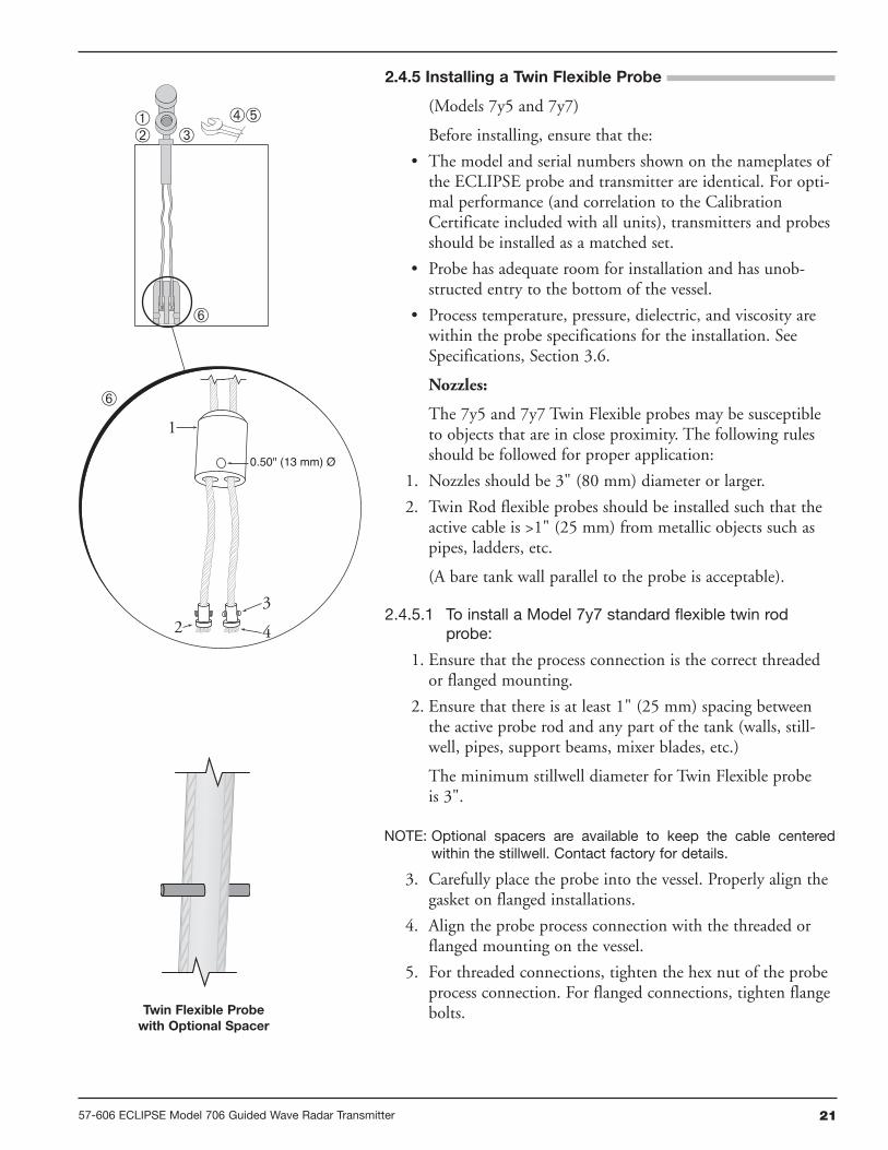
2.6.1 Bench Configuration
The ECLIPSE Model 706 transmitter can be easily config-ured at a test bench by connecting a standard 24 VDCpower supply directly to the transmitter terminals asshown in the accompanying diagram. An optional digitalmultimeter is shown in the event that mA current mea-surements are desired.

28 57-606 ECLIPSE Model 706 Guided Wave Radar Transmitter
NOTE: Current measurements taken at these test points are anapproximate value. Accurate current readings should betaken with the digital multimeter directly in series with theloop.
NOTE: When using a HART communicator for configuration, a mini-mum 250-ohm line load resistance is required. Refer to yourHART communicator manual for additional information.
NOTE: The transmitter can be configured without the probe. Pleasedisregard the “No Probe” diagnostic indicator that will appear.
2.6.2 Menu Traversal and Data Entry
The four push buttons offer various forms of functionalityfor navigation and data entry.
The Model 706 user interface is hierarchical in nature,best described as a tree structure. Each level in the treecontains one or more items. Items are either menu labelsor parameter names.
• Menu labels are presented in all capital letters
• Parameters are capital words
2.6.2.1 Navigating the Menu
UP moves to the previous item in the menu branch.
DOWN moves to the next item in the menu branch.
BACK moves back one level to the previous (higher)branch item.
ENTER enters into the lower level branch or switchesto the entry mode. Holding the ENTER down on anyhighlighted menu name or parameter will show helptext for that item.
2.6.2.2 Data Selection
This method is used for selecting configuration data froma specific list.
UP and DOWN to navigate the menu and high-light the item of interest
ENTER allows modification of that selection
UP and DOWN to choose new data selection
ENTER to confirm selection
Use BACK (Escape) key at any time to abort the pro-cedure and escape to previous branch item
Up Down Back Enter
+
–
+
–
Power Supply24 VDC
(-) negative(+) positive
TestCurrent Meter
G.P./I.S./Explosion Proof Model

2957-606 ECLIPSE Model 706 Guided Wave Radar Transmitter
2.6.2.3 Entering Numeric Data Using Digit Entry
This method is used to input numeric data, e.g., ProbeLength, set 4mA and set 20mA.
All numeric values are left-justified, and new values areentered from left to right. A decimal point can beentered after the first digit is entered, such that .9 isentered as 0.9.
Some configuration parameters can have a negativevalue. In this case, the leftmost position is reversed forthe sign (either "-" for a negative value, or "+" for a pos-itive value).
2.6.2.4 Entering Numeric Data Using Increment/Decrement
Use this method to input the following data into para-meters such as Damping and Failure Alarm.
Push button Keystroke Action
UpMoves up to the next highest digit (0,1,2,3,....,9or decimal point). If held down the digits scrolluntil the push button is released.
DownMoves up to the next lowest digit (0,1,2,3,....,9 ordecimal point). If held down the digits scroll untilthe push button is released.
Back
Moves the cursor to the left and deletes a digit. Ifthe cursor is already at the leftmost position,then the screen is exited without changing thepreviously saved value.
EnterMoves the cursor to the right. If the cursor islocated at a blank character position, the newvalue is saved.
Push button Keystroke Action
Up
Increments the displayed value. If held downthe digits scroll until the push button is released.Depending on which screen is being revised, theincrement amount may increase by a factor of 10after the value has been incremented 10 times.
Down
Decrements the displayed value. If held down thedigits scroll until the push button is released.Depending on which screen is being revised, thedecrement amount may increase by a factor of10 after the value has been decremented 10times.
BackReturns to the previous menu without changingthe original value, which is immediately redis-played.
EnterAccepts the displayed value and returns to theprevious menu.

30 57-606 ECLIPSE Model 706 Guided Wave Radar Transmitter
2.6.2.5 Entering Character Data
This method is used for parameters requiring alphanumericcharacter entry, such as for entering tags, etc.
General Menu Notes:
2.6.3 Password Protection
The ECLIPSE Model 706 transmitter has three levels ofpassword protection to restrict access to certain portions ofthe menu structure that affect the operation of the system.The user password can be changed to any numerical valueup to 59999. When the transmitter is programmed forpassword protection, a password is required wheneverconfiguration values are changed.
User Password
The User Password allows the customer to limit access tothe basic configuration parameters.
The default User Password installed in the transmitter atthe factory is 0. With a password of 0, the transmitter is nolonger password protected and any value in the basic usermenus can be adjusted without entering a confirmingpassword.
NOTE: If a User Password is not known or has been misplaced, themenu item New Password in the DEVICE SETUP/ADVANCEDCONFIG menu displays an encrypted value representing thepresent password. Contact Technical Support with thisencrypted password to retrieve the original User Password.
Push button Keystroke Action
UpMoves to the previous character (Z...Y...X...W).If held down, the characters scroll until the pushbutton is released.
DownMoves to the next item character (A...B...C...D).If held down, the characters scroll until the pushbutton is released.
Back
Moves the cursor back to the left. If the cursor isalready at the leftmost position, then the screenis exited without changing the original tag char-acters.
EnterMoves the cursor forward to the right. If thecursor is at the rightmost position, then thenew tag is saved.

3157-606 ECLIPSE Model 706 Guided Wave Radar Transmitter
Advanced Password
Certain portions of the menu structure that contain moreadvanced parameters are further protected by an AdvancedPassword.
This password will be provided, when necessary, by Factorytechnical support.
Factory Password
Calibration-related and other factory settings are furtherprotected by a Factory Password.
2.6.4 Model 706 Menu: Step-By-Step Procedure
The following tables provide a complete explanation of thesoftware menus displayed by the ECLIPSE transmitter. Themenu layout is similar between the local Keypad/LCDinterface, the DD, and the DTM.
Use these tables as a step-by-step guide to configure thetransmitter based on the desired measurement type from thefollowing selections:
• Level Only
• Interface & Level
• Level & Volume
• Flow
HOME SCREEN
The Home Screen consists of a “slide show” sequence ofMeasured Values screens which are rotated at 2-secondintervals. Each Home Measured Value screen can present upto four information items:
• HART Tag
• Measured ValueLabel, Numerical Value, Units
• StatusWill be displayed as text or optionally with NAMUR NE107 symbol
• Primary Value Bar Graph (shown in %)
The Home Screen presentation can be customized by view-ing or hiding some of these items. See DISPLAY CONFIGunder the DEVICE SETUP menu in Section 2.6.5 —Configuration Menu.
At left is an example of a Home Screen for a Model 706configured for a Level Only application.
Up Down Back Enter

32 57-606 ECLIPSE Model 706 Guided Wave Radar Transmitter
MAIN MENU
Pressing any key on the Home Screen will present the MainMenu, consisting of three basic menu labels shown in allcapital letters.
• DEVICE SETUP
• DIAGNOSTICS
• MEASURED VALUES
As shown, the reverse video represents a cursor identifyingthe selected item, which will appear in reverse video on theLCD. The actions of the keys at this point are:
NOTES: 1. Items and parameters that are shown in lower level menuswill depend on the Measurement Type chosen. Those para-meter not applicable to the present Measurement Type willbe hidden.
2. Holding down the Enter key when the cursor is highlightedover a parameter or menu will provide additional informationabout that item.
DEVICE SETUP
Choosing DEVICE SETUP from the MAIN MENU willresult in an LCD presentation as shown at left.
The small down arrow shown at the right hand side of thescreen is the indication that more items are available belowand can be accessed by pressing the DOWN key.
Section 2.6.5 shows the entire tree menu for the Model 706DEVICE SETUP Menu.
DIAGNOSTICS
Refer to Section 3.3.4
MEASURED VALUES
Allows the user to scroll through all of the availablemeasured values for the measurement type chosen.
Push button Keystroke Action
UpNo action as the cursor is already at the firstitem in the MAIN MENU
Down Moves the cursor to DIAGNOSTICS
BackMoves back to HOME SCREEN, the levelabove MAIN MENU
Enter Presents the selected item, DEVICE SETUP

3357-606 ECLIPSE Model 706 Guided Wave Radar Transmitter
Home Screen
Main Menu
Device Setup Quick StartIdentityBasic ConfigI/O ConfigDisplay ConfigAdvanced ConfigFactory Config
Level Units:InchesFeetMillimetersCentimetersMeters
Probe Model:7YD Coax HTHP7YF Sngl Rod Tanks7YG Sngl Rod Cages7YJ Sngl Rod Cages7YL Sngl Rod Cages7YM Sngl Rod Tanks7YN Sngl Rod Tanks7YP Coax HP7YS Coax Steam7YT Coax Std7Y1 Sngl Flex Std7Y2 Sngl Flex Bulk7Y4 Sngl Flex Cages7Y5 Twin Flex Bulk7Y6 Sngl Flx HTHP Cage7Y7 Twin Flex Clad
Probe Mount:NPTBSPFlangeNPT/FlushingBSP/FlushingFlange/FlushingHygienic
Probe Length:12 inches to 100 feet(30 cm to 30 m)
Level Offset:-25 feet to +75 feet(-7.6 m to 22.9 m)
Dielectric Range:Below 1.71.7 to 3.03.0 to 10Above 10
4 mA Set Point (LRV):-25 feet to +175 feet(-7.6 m to 53 m)
20 mA Set Point (URV):-25 feet to +175 feet(-7.6 m to 53 m)
Failure Alarm:22 mA3.6 mAHold
Level Units:InchesFeetMillimetersCentimetersMeters
Probe Model:7YD Coax HTHP7YF Sngl Rod Std7YG Sngl Rod Std7YJ Sngl Rod HTHP7YL Sngl Rod HP7YM Sngl Rod HP7YN Sngl Rod HTHP7YP Coax HP7YS Coax Steam7YT Coax Std7Y1 Sngl Flex Std7Y2 Sngl Flex Bulk7Y4 Sngl Flex Cages7Y5 Twin Flex Bulk7Y6 Sngl Flx HTHP Cage7Y7 Twin Flex Clad
Probe Coating: (7yF only)None (Bare)PFA Coated
Probe Mount:NPTBSPFlangeNPT/FlushingBSP/FlushingFlange/FlushingHygienic
Probe Length:12 inches to 100 feet(30 cm to 30 m)
Level Offset:-25 feet to +75 feet(-7.6 m to 22.9 m)
Dielectric Range:Below 1.71.7 to 3.03.0 to 10Above 10
Home Screen
Main Menu
Device Setup Quick StartIdentity
Basic ConfigI/O ConfigDisplay ConfigAdvanced ConfigFactory Config
Product Name (read only)
Magnetrol S/N (read only)
Hardware Version (read only)
Firmware Version (read only)
LongTag
Measurement Type:Level OnlyInterface and LevelVolume and LevelFlow
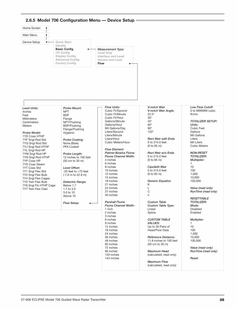
2.6.5 Model 706 Configuration Menu — Device Setup

34 57-606 ECLIPSE Model 706 Guided Wave Radar Transmitter
Level Units:InchesFeetMillimetersCentimetersMeters
Probe Model:7YD Coax HTHP7YF Sngl Rod Tanks7YG Sngl Rod Cages7YJ Sngl Rod Cages7YL Sngl Rod Cages7YM Sngl Rod Tanks7YN Sngl Rod Tanks7YP Coax HP7YS Coax Steam7YT Coax Std7Y1 Sngl Flex Std7Y2 Sngl Flex Bulk7Y4 Sngl Flex Cages7Y5 Twin Flex Bulk7Y6 Sngl Flx HTHP Cage7Y7 Twin Flex Clad
Probe Coating: (7yF only)None (Bare)PFA Coated
Probe Mount:NPTBSPFlangeNPT/FlushingBSP/FlushingFlange/FlushingHygienic
Probe Length:12 inches to 100 feet(30 cm to 30 m)
Level Offset:-25 feet to +75 feet(-7.6 m to 22.9 m)
Dielectric Range:Below 1.71.7 to 3.03.0 to 10Above 10
Upr Dielectric:1.2 to 10
Home Screen
Main Menu
Device Setup Quick StartIdentityBasic ConfigI/O ConfigDisplay ConfigAdvanced ConfigFactory Config
Measurement Type:Level OnlyInterface and LevelVolume and LevelFlow
Home Screen
Main Menu
Device Setup Quick StartIdentityBasic ConfigI/O ConfigDisplay ConfigAdvanced ConfigFactory Config
Measurement Type:Level OnlyInterface and LevelVolume and LevelFlow
Volume Units:Cubic FeetCubic InchesGallonsMillilitersLiters
Vessel Type:RectangularHorizontal/FlatHorizontal/EllipseHorizontal/SphericalSphericalVertical/FlatVertical/EllipseVertical/SphericalVertical/ConicalCustom Table
Vessel Dimensions:(not used with Custom Table)RadiusEllipse DepthConical HeightWidthLength
Custom Table Setup:Custom Table Type:LinearSpline
Level Input Source:KeypadSensor
CUSTOM TABLE VALUES:Up to 30 Pairs ofLevel/Volume Data
Level Units:InchesFeetMillimetersCentimetersMeters
Probe Model:7YD Coax HTHP7YF Sngl Rod Std7YG Sngl Rod Std7YJ Sngl Rod HTHP7YL Sngl Rod HP7YM Sngl Rod HP7YN Sngl Rod HTHP7YP Coax HP7YS Coax Steam7YT Coax Std7Y1 Sngl Flex Std7Y2 Sngl Flex Bulk7Y4 Sngl Flex Cages7Y5 Twin Flex Bulk7Y6 Sngl Flx HTHP Cage7Y7 Twin Flex Clad
Probe Mount:NPTBSPFlangeNPT/FlushingBSP/FlushingFlange/FlushingHygienic
Probe Coating:None (Bare)PFA Coated
Probe Length:12 inches to 100 feet(30 cm to 30 m)
Level Offset:-25 feet to +75 feet(-7.6 m to 22.9 m)
Dielectric Range:Below 1.71.7 to 3.03.0 to 10Above 10
Upr Dielectric:1.2 to 10
Probe Mount:NPTBSPFlangeNPT/FlushingBSP/FlushingFlange/FlushingHygienic
Probe Coating:None (Bare)PFA Coated
Probe Length:12 inches to 100 feet(30 cm to 30 m)
Level Offset:-25 feet to +75 feet(-7.6 m to 22.9 m)
Dielectric Range:Below 1.71.7 to 3.03.0 to 10Above 10
Upr Dielectric:1.2 to 10
Level Units:InchesFeetMillimetersCentimetersMeters
Probe Model:7YD Coax HTHP7YF Sngl Rod Std7YG Sngl Rod Std7YJ Sngl Rod HTHP7YL Sngl Rod HP7YM Sngl Rod HP7YN Sngl Rod HTHP7YP Coax HP7YS Coax Steam7YT Coax Std7Y1 Sngl Flex Std7Y2 Sngl Flex Bulk7Y4 Sngl Flex Cages7Y5 Twin Flex Bulk7Y6 Sngl Flx HTHP Cage7Y7 Twin Flex Clad
Probe Coating: (7yF only)None (Bare)PFA Coated
Probe Mount:NPTBSPFlangeNPT/FlushingBSP/FlushingFlange/FlushingHygienic
Probe Length:12 inches to 100 feet(30 cm to 30 m)
Level Offset:-25 feet to +75 feet(-7.6 m to 22.9 m)
Dielectric Range:Below 1.71.7 to 3.03.0 to 10Above 10
Volume Setup:
Volume Units:Cubic FeetCubic InchesGallonsMillilitersLiters
Vessel Type:RectangularHorizontal/FlatHorizontal/EllipseHorizontal/SphericalSphericalVertical/FlatVertical/EllipseVertical/SphericalVertical/ConicalCustom Table
Vessel Dimensions:(not used with Custom Table)RadiusEllipse DepthConical HeightWidthLength
Custom Table Setup:Custom Table Type:LinearSpline
Level Input Source:KeypadSensor
CUSTOM TABLE VALUES:Up to 30 Pairs ofLevel/Volume Data
2.6.5 Model 706 Configuration Menu — Device Setup
3557-606 ECLIPSE Model 706 Guided Wave Radar Transmitter
Home Screen
Main Menu
Device Setup Quick StartIdentityBasic ConfigI/O ConfigDisplay ConfigAdvanced ConfigFactory Config
Measurement Type:Level OnlyInterface and LevelVolume and LevelFlow
Flow Units:Cubic Ft/SecondCubic Ft/MinuteCubic Ft/HourGallons/MinuteGallons/HourMil Gallons/DayLiters/SecondLiters/MinuteLiters/HourCubic Meters/Hour
Flow Element:Palmer-Bowlus FlumeFlume Channel Width:4 inches6 inches8 inches10 inches12 inches15 inches18 inches21 inches24 inches27 inches30 inches
Parshall FlumeFlume Channel Width:1 inch2 inches3 inches6 inches9 inches12 inches18 inches24 inches36 inches48 inches60 inches72 inches96 inches120 inches144 inches
V-notch WeirV-notch Weir Angle:22.5°30°45°60°90°120°
Rect Weir with Ends0 to 215.0 feet(0 to 65 m)
Rect Weir w/o Ends0 to 215.0 feet(0 to 65 m)
Cipolletti Weir0 to 215.0 feet(0 to 65 m)
Generic EquationKLCn
Custom TableCustom Table Type:LinearSpline
CUSTOM TABLE VALUES:Up to 30 Pairs ofHead/Flow Data
Reference Distance:11.8 inches to 100 feet(30 cm to 30 m)
Maximum Head(calculated, read only)
Maximum Flow(calculated, read only)
Low Flow Cutoff:0 to 9999999 cubic ft/min
TOTALIZER SETUP:Units:Cubic FeetGallonsMil GallonsLitersMil LitersCubic Meters
NON-RESET TOTALIZER:Multiiplier:1101001,00010,000100,000
Value (read only)RunTime (read only)
RESETTABLE TOTALIZER:Mode:DisabledEnabled
Multiplier:1101001,00010,000100,000
Value (read only)RunTime (read only)
Reset
Level Units:InchesFeetMillimetersCentimetersMeters
Probe Model:7YD Coax HTHP7YF Sngl Rod Std7YG Sngl Rod Std7YJ Sngl Rod HTHP7YL Sngl Rod HP7YM Sngl Rod HP7YN Sngl Rod HTHP7YP Coax HP7YS Coax Steam7YT Coax Std7Y1 Sngl Flex Std7Y2 Sngl Flex Bulk7Y4 Sngl Flex Cages7Y5 Twin Flex Bulk7Y6 Sngl Flx HTHP Cage7Y7 Twin Flex Clad
Probe Mount:NPTBSPFlangeNPT/FlushingBSP/FlushingFlange/FlushingHygienic
Probe Coating:None (Bare)PFA Coated
Probe Length:12 inches to 100 feet(30 cm to 30 m)
Level Offset:-25 feet to +75 feet(-7.6 m to 22.9 m)
Dielectric Range:Below 1.71.7 to 3.03.0 to 10Above 10
Flow Setup:
2.6.5 Model 706 Configuration Menu — Device Setup

36 57-606 ECLIPSE Model 706 Guided Wave Radar Transmitter
Home Screen
Main Menu
Device Setup Quick StartIdentityBasic ConfigI/O Config
Display ConfigAdvanced ConfigFactory Config
Primary Variable
4 mA Set Pt (LRV):-25 to +175 feet ([Upr] Level, Ifc Level)(-7.6 m to 53 m)2.0 inches to 100 feet (Upr Thickness)(5 cm to 30 m)0 to 9999999 gals (Volume)0 to 9999999 cubic ft/min (Flow) 20 mA Set Pt (URV):-25 to +175 feet ([Upr] Level, Ifc Level)(-7.6 m to 53 m)2.0 inches to 100 feet (Upr Thickness)(5 cm to 30 m)0 to 9999999 cf (Volume)0 to 9999999 cfs (Flow) Failure Alarm:22 mA3.6 mAHold
Damping:0 to 10 seconds
Language:EnglishFrenchGermanSpanishRussian
Status Symbol:HideView
Long Tag:HideView
PV Bar Graph:HideView
Level:HideView
Ifc Level:(Interface and Level mode only)HideView
Upr Thickness:(Interface and Level mode only)HideView
Volume:(Volume and Level mode only)HideView
Flow:(Flow mode only)HideView
Head:(Flow mode only)HideView
Distance:HideView
% Output:HideView
Analog Output:HideView
NRTotalizer:(Flow mode only)HideView
R Totalizer:(Flow mode only)HideView
Upr Echo Strength:(Interface and level mode only)HideView
Ifc Echo Strength:(Interface and level mode only)HideView
Elec Temp:HideView
Probe Buildup:(Buildup Detection = On)HideView
2.6.5 Model 706 Configuration Menu — Device Setup

3757-606 ECLIPSE Model 706 Guided Wave Radar Transmitter
Home Screen
Main Menu
Device Setup Quick StartIdentityBasic ConfigI/O ConfigDisplay ConfigAdvanced ConfigFactory Config
Sensitivity:0 to 100 echo strength units
Blocking Distance:-7.5 to +100 feet(-2 m to 30 m)
Safety Zone Alarm:None3.6 mA22 mALatched 3.6 mALatched 22 mA
Safety Zone Height:(not used when Safety Alarm is None)2 inches to 100 feet(5 cm to 30 m)
Reset SZ Alarm (used when Safety Alarm is Latch 3.6 mA or Latch 22 mA)
Failure Alarm Delay:0 to 5 seconds
Level Trim:-2.00 to + 2.00 feet(-0.6 m to + 0.6 m)
THRESHOLD SETTINGSLvl Thresh Mode:Auto Largest(not used with Interface and Level)Fixed ValueAuto UpperSloped
Sloped Start Value:(When Lvl Thresh Mode is Sloped)
Lvl Thresh Value:0 to 100 echo strength unitsSloped Start Value(used when Lvl Thresh Mode is Sloped)0 to 100 echo strength units
Sloped End Dist:(used when Lvl Thresh Mode is Sloped)25 to 100 feet(7 to 30 m)
Ifc Lvl Thresh Mode:(Interface and Level only)Auto LargestFixed Value
Ifc Lvl Thresh Value:(Interface and Level only)0 to 100 echo strength units
EoP Thresh Mode:Auto LargestFixed Value
EoP Thresh Value:0 to 100 echo strength units
ENDofPROBE ANALYSIS:EoP Polarity:PositiveNegative
EoP Analysis:(not used with Interface and Level)OffOn
EoP Dielectric:(not used with Interface and Level)1.20 to 9.99
ECHO REJECTION:View Echo Curve
REJECTION CONTROL:Reject Curve State:OffDisabled[Enabled]
Reject Curve Mode:LevelDistance
Saved Medium
NEW REJECT CURVE:Actual MediumSave Reject Curve
Compensation:NoneAutoManualVapor Dielectric1.00 to 2.00
HF Cable Length:Integral3 feet12 feet
Buildup Detection:OffOn
ANALOG OUTPUT:HART Poll Address:0 to 63
Analog Output Mode:Disabled (Fixed)Enabled (PV)[Fixed Current Value]4 to 20 mA
ADJUST ANALOG OUTPUT:Adjust 4mAAdjust 20mA
New User Password:0 to 59,999
CONFIG CHANGED:Indicator Mode:DisabledEnabled
Reset Config Chngd:Reset?NoYes
Reset Parameters:NoYes
2.6.5 Model 706 Configuration Menu — Device Setup

38 57-606 ECLIPSE Model 706 Guided Wave Radar Transmitter
Home Screen
Main Menu
Device Setup Quick StartIdentityBasic ConfigI/O ConfigDisplay ConfigAdvanced ConfigFactory Config Fiducial Gain:
0 to 255 (read only)
Fid Threshold Value
SZ Hysteresis (Safe Zone Hysteresis):(not used when Safe Zone Alarm is None)0 to 100 feet(0 to 30 m)
PROBE TARGET (Compensation = Auto):Probe Target Mode Off Run CalibrateTarg Calib TicksTarget Ticks
Elec Temp Offset
Ifc Boundary Offset
NAP Value
Factory Reset
FACTORY CALIB(Factory password required)WindowFiducial TicksConversion FactorScale Offset
2.6.5 Model 706 Configuration Menu — Device Setup

3957-606 ECLIPSE Model 706 Guided Wave Radar Transmitter
2.7 Configuration Using HART
A HART (Highway Addressable Remote Transducer)remote unit, such as a HART communicator, can be used toprovide a communication link to the ECLIPSE Model 706transmitter. When connected to the control loop, the samesystem measurement readings shown on the transmitter arealso shown on the communicator. The communicator canalso be used to configure the transmitter.
The HART communicator may need to be updated toinclude the ECLIPSE Model 706 software (DeviceDescriptions). Refer to your HART Communicator Manualfor update instructions.
2.7.1 Connections
A HART communicator can be operated from a remotelocation by connecting it to a remote junction or by con-necting it directly to the terminal block in the wiring com-partment of the ECLIPSE transmitter.
HART uses the Bell 202 frequency shift keying techniqueof high-frequency digital signals. It operates on the 4–20mA loop and requires 250 Ω load resistance. A typical con-nection between a communicator and the ECLIPSE trans-mitter is shown at left.
2.7.2 HART Communicator Display
A typical communicator display is an 8-line by 21-characterLCD. When connected, the top line of each menu displaysthe model (Model 706) and its tag number or address. Fordetailed operating information, refer to the instructionmanual provided with the HART communicator.
2.7.3 HART Revision Table
Model 706 1.x
HART Version HCF Release Date Compatible with 706 SoftwareDev Rev 1, DD Rev 2 December 2012 Version 1.0 and later
2.7.4 HART Menu – Model 706
The ECLIPSE transmitter HART menu trees are shown inthe following pages. Open the menu by pressing thealphanumeric key 4, then Device Setup, to display thesecond-level menu.
+-
Junction
RL > 250 Ω
ControlRoom
DisplayPowerSupply
CurrentMeter

40 57-606 ECLIPSE Model 706 Guided Wave Radar Transmitter
2.7.4 HART Menu – Model 706
1 Enter Password 2 Level Units 3 Probe Model 4 Probe Coating 5 Probe Mount 6 Probe Length 7 Measurement Type 8 Level Offset 9 Dielectric Range 10 Upper Dielectric 11 Basic Config Diagram
1 PV 2 PV Loop Current 3 PV % Range 4 Device Setup 5 Setup Wizard 6 Diagnostics 7 Measured Values
1 Level 2 Ifc Level 3 Upr Thickness 4 Volume 5 Flow 6 Head 7 Distance 8 R Totalizer Value 9 NR Totalizer Value 10 Echo Strength 11 Ifc Echo Strength 12 Buildup 13 Temperature
1 Identity
2 Basic Config
3 Volume Config
4 Flow Config
5 I/O Config
6 Local Display Config 7 Advanced Config 8 Factory Config
1 Enter Password 2 PV is 3 PV AmA Set Point 4 PV 20mA Set Point 5 PV Failure Alarm 6 Damping 7 I/O Config Diagram 8 Variable Selection 9 Set Points
1 Enter Password 2 Flow Units 3 Flow Element 4 Flume Channel Width 5 V-Notch Angle 6 Crest Length 7 Custom Table Type 8 Reference Distance 9 Maximum Head 10 Maximum Flow 11 Low Flow Cutoff 12 General Equation Factors 13 Flow Diagrams 14 Custom Table 15 Totalizer Setup
1 Manufacturer 2 Product Name 3 Magnetrol S/N 4 Hardware Version 5 Firmware Version 6 ConfigChg Counter 7 Final Assy Number 8 Device ID 9 Universal Revision 10 Field Device Revision 11 Software Revision 12 Num Preambles
1 Enter Password 2 Volume Units 3 Vessel Type 4 Length 5 Width 6 Radius 7 Ellipse Depth 8 Conical Height 9 Table Type 10 Vessel Diagrams 11 Custom Table Type 12 Level Input Source 13 Custom Table Length 14 Custom Table
1 K 2 L 3 C 4 n
1 Totalizer Units 2 NR Mult 3 NR Totalizer Value 4 NR Totalizer RunTime 5 R Totalizer Mode 6 R Totalizer Mult 7 R Totalizer Value 8 R Totalizer RunTime 9 Totalizer
1 SV is 2 TV is 3 QV is
1 Lvl 4mA Set Point 2 Lvl 20mA Set Point 3 Ifc 4mA Set Point 4 Ifc 20mA Set Point 5 Thk 4mA Set Point 6 Thk 20mA Set Point 7 Vol 4mA Set Point 8 Vol 20mA Set Point 9 Flo 4mA Set Point 10 Flo 20mA Set Point
1 Enter Password 2 Tag 3 Long Tag 4 Descriptor 5 Date 6 Message 7 Date/Time/Initials 8 Factory Identity

4157-606 ECLIPSE Model 706 Guided Wave Radar Transmitter
2.7.4 HART Menu – Model 706
1 Level Threshold Mode 2 Level Threshold Value 3 Sloped Start Value 4 Sloped End Distance 5 Interface Level Threshold Mode 6 Interface Level Threshold Value 7 EOP Threshold Mode 8 EOP Threshold Value
1 Compensation Mode 2 Vapor Dielectric
1 Identity 2 Basic Config 3 Volume Config 4 Flow Config 5 I/O Config
6 Local Display Config
7 Advanced Config
8 Factory Config
1 Probe Target Mode 2 Target Calib 3 Target Ticks 4 Auto Target Calib
1 EOP Polarity 2 EOP Analysis 3 EOP Dielectric
1 Enter Password 2 Sensitivity 3 Blocking Distance 4 Safety Zone Settings 5 Failure Alarm Delay 6 Level Trim 7 Adv Config Diagram 8 Echo Rejection 9 Threshold Settings 10 End-of-Probe Settings 11 Compensation 12 HF Cable Length 13 Buildup Detection 14 Analog Output 15 New User Password 16 Reset Paramaters
1 Enter Password2 Fiducial Gain3 Fid Thresh Value 4 Probe Target 5 Elec Temp Offset 6 Ifc Boundary Offset7 NAPValue 8 Factory Reset9 Factory Param 2
1 Safety Zone Alarm 2 Safety Zone Height 3 Reset SZ Alarm
1 Enter Password 2 Language 3 Status Symbol 4 Long Tag 5 PV Bar Graph 6 Display Setup Diagram 7 Measured Values
1 Reject Curve State 2 Reject Curve Mode 3 Saved Media Location 4 New Rejection Curve
1 Poll Address 2 Analog Output Mode 3 Fixed Loop Current 4 Adjust Analog Output 5 4mA Trim Value 6 20mA Trim Value 7 Fdbk 4mA Trim Value 8 Fdbk 20mA Trim Value
1 Window 2 Fiducial Ticks 3 Conversion Factor 4 Scale Offset 5 7YK Scale Offset
10 Factory Param 311 Factory Param 4 12 Factory Calib

42 57-606 ECLIPSE Model 706 Guided Wave Radar Transmitter
2.7.4 HART Menu – Model 706
1 PV 2 PV Loop Current 3 PV % Range 4 Device Setup 5 Setup Wizard 6 Diagnostics 7 Measured Values
1 Present Status
2 Event History
3 Advanced Diagnostics
4 Echo Curves 5 Echo History 6 Trend Data
1 NE107 Category 2 NE107 Highest Active Indicator 3 Add’l Device Status 4 Reset Config Changed 5 NAMUR NE 107 Setup 6 NE 107 Simulation Mode 7 Enter Password
1 NE 107 Mapping 2 Reset NE 107 Mapping
1 Event Log 2 Refresh History 3 Reset History 4 Set Clock
1 Internal Values 2 Elec Temperatures 3 Transmitter Tests 4 Probe Buildup
1 Status 0 2 Status 1 3 Status 2 4 Status 3 5 Status 4 6 Status 5
1 Fiducial Ticks 2 Fiducial Strength 3 Level Ticks 4 Echo Strength 5 Distance 6 Ifc Ticks 7 Ifc Echo Strength 8 Ifc Boundary 9 Ifc Medium 10 Targ Calib Ticks 11 Target Ticks 12 Target Strength 13 Vapor Apparent Diel 14 EoP Ticks 15 EoP Strength 16 EoP Distance (mm) 17 EoP Apparent Diel 18 Fdbk Current
1 Present Temperature 2 Max Temperature 3 Min Temperature 4 Reset Min/Max Temps
1 Analog OutputTest
1 Percent of Level Threshold 2 Buildup Location 3 Buildup Rate 4 Check

4357-606 ECLIPSE Model 706 Guided Wave Radar Transmitter
2.7.4 HART Menu – Model 706
1 PV 2 PV Loop Current 3 PV % Range 4 Device Setup 5 Setup Wizard 6 Diagnostics 7 Measured Values
1 Present Status 2 Event History 3 Advanced Diagnostics 4 Echo Curves
5 Echo History
6 Trend Data
1 Echo Graph 2 Curve 1 3 Curve 2 4 Refresh Graph 5 Zoom 6 Save Ref Echo Curve 7 New Rejection Curve 8 Parameters
1 Echo Graph 2 Curve 1 3 Curve 2 4 Refresh Graph 5 Zoom 6 Echo History Log 7 Refresh History 8 History Setup 9 Delete History 10 Set Clock
1 Enter Password 2 Dielectric Range 3 Sensitivity 4 Blocking Distance 5 Lvl Thresh Mode 6 Sloped Start Value 7 Lvl Thresh Value 8 Sloped End Distance 9 Ifc Lvl Thresh Value 10 EoP Thresh Value
1 Echo History Mode 2 Trigger Events 3 Time Triggers 4 Set Clock 5 Enter Password
1 Trend Data 2 Level 3 Ifc Level 4 Upr Thickness 5 Volume 6 Flow 7 Loop 8 Range 9 Analog Output 10 % Output 11 Echo Strength 12 Ifc Echo Strength 13 Data Log Setup 1 Trending Variables
2 Time Setup 3 Set Clock 4 Enter Password

44 57-606 ECLIPSE Model 706 Guided Wave Radar Transmitter
2.8 FOUNDATION fieldbus™
Digital Communications
2.8.1 Overview
This section is only intended to be a quick overview ofthe FOUNDATION fieldbus™ protocol. Refer to I/OManual 57-656 for details on the FOUNDATION fieldbus™
version of the ECLIPSE Model 706.
FOUNDATION fieldbus™ is a digital communicationssystem that serially interconnects devices in the field. AFieldbus system is similar to a Distributed Control System(DCS) with two exceptions:
1. Although a Fieldbus system can use the same physicalwiring as a 4–20 mA device, Fieldbus devices are not con-nected point-to-point, but rather are multi-dropped on asingle pair of wires (referred to as a segment).
2. Fieldbus is a system that allows the user to distribute controlacross a network.
Unlike 4–20 mA analog installations in which the two wirescarry a single variable (the varying 4–20 mA current), a dig-ital communications protocol such as Fieldbus considers thetwo wires as a network. The network can carry manyprocess variables as well as other information. The ECLIPSEModel 706FF transmitter is a FOUNDATION fieldbus regis-tered device that communicates with the H1 FOUNDATION
Fieldbus protocol operating at 31.25 kbits/sec. The H1physical layer is an approved IEC 61158 standard. A typicalFieldbus installation is shown at left.
An IEC61158 shielded twisted pair wire segment can be aslong as 6234 feet (1900 meters) without a repeater. Up tofour repeaters per segment can be used to extend the distance.The maximum number of devices allowed on a Fieldbussegment is 32 although this depends on the current drawof the devices on any given segment.
Details regarding cable specifications, grounding, termina-tion, and other network information can be found in IEC61158 or at www.fieldbus.org.
2.8.2 Function Blocks
The function of a Fieldbus device is determined by thearrangement of a system of blocks defined by the FieldbusFoundation. The types of blocks used in a typical UserApplication are described as follows:
Control Room
Power Supply
Terminator
6234 feet (1900 meters) maximum
PC
Terminator
PowerConditioner
Typical Fieldbus Installation

4557-606 ECLIPSE Model 706 Guided Wave Radar Transmitter
Resource Block describes the characteristics of the Fieldbusdevice such as the device name, manufacturer, and serialnumber.
Transducer Blocks contain information such as configura-tion information and sensor type. They are used to connectthe sensor to the input function blocks.
Function Blocks are built into the Fieldbus devices as needed to provide the desired control system behavior. Theinput and output parameters of function blocks can belinked over the Fieldbus. There can be numerous functionblocks in a single user application.
The Model 706 FF transmitter contains:
• One (1) Resource Block(RB)
• Three (3) custom Transducer Blocks (TB)
• Eight (8) Analog Input Function Blocks(AI)
• Two (2) PID Blocks(PID)
• One Integrator Block(IT)
• One (1) Arithmetic Block(AR)
• One (1) Input Selector Block(IS)
• One (1) Signal Characterizer Block (SC)
2.8.3 Intrinsically Safe
The H1 protocol supports Intrinsic Safety (IS) applicationswith bus powered devices. To accomplish this, anIntrinsically Safe (IS) barrier is placed between the powersupply in the safe area and the device in the hazardous area.
H1 also supports the Fieldbus Intrinsically Safe Concept(FISCO) model which allows more field devices in a network.The FISCO model considers the capacitance and induc-tance of the wiring to be distributed along its entire length.With that assumption, the stored energy during a fault willbe less and more devices are permitted on a pair of wires.Instead of the conservative entity model, which only allowsabout 90 mA of current, the FISCO model allows a maxi-mum of 110 mA for Class II C installations and 240 mAfor Class II B installations.
FISCO certifying agencies have limited the maximum seg-ment length to 1000 meters because the FISCO model doesnot rely on standardized ignition curves.
The ECLIPSE Model 706FF is available with entity IS,FISCO IS, and explosion proof approvals.

46 57-606 ECLIPSE Model 706 Guided Wave Radar Transmitter
3.0 Reference Information
This section presents an overview of the operation of theECLIPSE Model 706 Guided Wave Radar LevelTransmitter, information on troubleshooting common prob-lems, listings of agency approvals, lists of replacement andrecommended spare parts, and detailed physical, functional,and performance specifications.
3.1 Transmitter Description
The ECLIPSE Model 706 is a loop-powered two-wire,24 VDC, level transmitter based on the concept of GuidedWave Radar.
The ECLIPSE Model 706 electronics are housed in anergonomic housing comprised of two tandem compartmentsangled at a 45-degree angle for ease of wiring and calibra-tion. These two compartments connect via a watertightfeedthrough.
3.2 Theory of Operation
3.2.1 Guided Wave Radar
Guided Wave Radar (GWR) combines Time DomainReflectometry (TDR), Equivalent Time Sampling (ETS)and modern low power circuitry. This synthesis of technolo-gies brings to the level market a high-speed radar circuit(speed of light transmission). The electromagnetic pulses arepropagated via a waveguide that yields a system many timesmore efficient than through-air radar.
3.2.2 Time Domain Reflectometry (TDR)
TDR uses pulses of electromagnetic (EM) energy to mea-sure distances or levels. When a pulse reaches a dielectricdiscontinuity (created by the surface of a process medium),part of the energy is reflected. The larger the dielectricdiscontinuity, the larger the amplitude (strength) of thereflection.
Although TDR is relatively new to the industrial level mea-surement industry, it has been used for decades in the tele-phone, computer, and power transmission industries. Inthese industries, TDR is used to successfully find wire orcable breaks and shorts. An EM pulse is sent through thewire, traveling unimpeded until it finds line damage dueto a break or short. A reflection is then returned from thedamaged area of the wire, enabling a timing circuit topinpoint the location.
A small amount of energy continues down the probe in a low dielectric fluid, e.g. hydrocarbon
Air εr = 1
Media εr > 1.4
24 VDC, 4-20 mA Loop Powered
A reflection is developed off the liquid surface
Transmit Pulse

4757-606 ECLIPSE Model 706 Guided Wave Radar Transmitter
In the ECLIPSE transmitter, a waveguide with a characteristicimpedance in air is used as a probe. When part of the probeis immersed in a material other than air, there is lowerimpedance due to the fact that a liquid will have a higherdielectric constant than air. When an EM pulse is sentdown the probe and meets the dielectric discontinuity thatoccurs at the air/liquid surface, a reflection is generated.
3.2.3 Equivalent Time Sampling (ETS)
ETS (Equivalent Time Sampling) is used to measure thehigh speed, low power EM energy. ETS is a critical key inthe application of TDR to vessel level measurement technol-ogy. The high speed EM energy (1000 ft/s) is difficult tomeasure over short distances and at the resolution requiredin the process industry. ETS captures the EM signals in realtime (nanoseconds) and reconstructs them in equivalenttime (milliseconds), which is much easier to measure withtoday’s technology.
ETS is accomplished by scanning the waveguide to collectthousands of samples. Approximately 5 scans are taken persecond; each scan gathers more than 30,000 samples.
3.2.4 Interface Detection
The ECLIPSE Model 706, when used with the appropriateprobes, is a transmitter capable of measuring both an upperlevel and an interface level. It is required that the upperliquid have a dielectric constant between 1.4 and 10 and thetwo liquids have a difference in dielectric constants greaterthan 10. A typical application would be oil over water, withthe upper layer of oil being non-conductive with a dielectricconstant of approximately 2 and the lower layer of waterbeing very conductive with a dielectric constant of approxi-mately 80. This interface measurement can only be accom-plished when the dielectric constant of the upper medium islower than the dielectric constant of the lower medium.
As mentioned above ECLIPSE Guided Wave Radar is basedupon the technology of TDR, which utilizes pulses of elec-tromagnetic energy transmitted down a wave guide (probe).When the transmitted pulse reaches a liquid surface that hasa higher dielectric constant than the air (dielectric constantof 1) in which it is traveling, the pulse is reflected and ultrahigh speed timing circuitry provides an accurate measure ofliquid level. Even after some of the pulse is reflected fromthe upper surface, energy continues down the length of theprobe through the upper liquid. The pulse is again reflectedwhen it reaches the higher dielectric lower liquid (refer tofigure at left). Since the propagation speed of the signalthrough the upper liquid is dependent on the dielectric
Low DielectricMedium(e.g. oil, ε = 2)
Air(ε = 1)
High DielectricMedium(e.g. water, ε = 80)
Emulsion Layer
ReferenceSignal
Upper LevelSignal
InterfaceLevelSignal
Time
Interface Detection

48 57-606 ECLIPSE Model 706 Guided Wave Radar Transmitter
constant of the medium in which it is traveling, the dielectricconstant of the upper liquid must be known to accuratelydetermine the interface level.
The thickness of the upper layer can be determined byknowing the time between the first and second reflectionsas well as the upper layer dielectric constant.
In order to properly process the reflected signals, theModel 706 is specified for those applications where thethickness of the upper layer is greater than 2 inches. Themaximum upper layer is typically limited to the length ofthe probe.
Emulsion LayersAs emulsion (rag) layers can decrease the strength of thereflected signal, GWR offers best performance in applica-tions having clean, distinct layers. However, the ECLIPSEModel 706 transmitter will operate in most emulsions andtend to read the top of the emulsion layer. Contact thefactory for application assistance and questions regardingemulsion layers.
3.2.5 Saturated Steam Applications(Boilers, Feedwater Heaters, etc.)
As the temperature of a saturated steam applicationincreases, the dielectric constant of the steam vapor spacealso increases. This increase in vapor space dielectric causesa delay in the GWR signal propagation as it travels downthe probe, causing the liquid level to appear lower thanactual.
NOTE: The measurement error associated with this propagation delaydoes depend on temperature and is a function of the squareroot of the vapor space dielectric constant. For example, withno compensation, a +450° F (+230° C) application would showa level error of about 5.5%, while a +600° F (+315° C) applica-tion would show an error approaching 20%!
The ECLIPSE Model 706 transmitter and Model 7ySCoaxial Steam probe provide a unique solution to thisapplication. The effects of the changing steam conditionscan be compensated for by utilizing a mechanical steamtarget placed inside and near the top of the Model 7yScoaxial probe.
Knowing exactly where the target is located at room tem-perature, and then continuously monitoring its apparentlocation, the vapor space dielectric can be back-calculated.Knowing the vapor space dielectric, accurate compensationof the actual liquid level reading is accomplished.

4957-606 ECLIPSE Model 706 Guided Wave Radar Transmitter
This is a patented technique with two US Patents(US 6642801 and US 6867729) issued for both themechanical target concept and the associated softwarealgorithm.
Contact the factory for additional information relating tosaturated steam applications.
3.2.6 Overfill Capability
Although agencies like WHG or VLAREM certify Overfillproof protection, defined as the tested, reliable operationwhen the transmitter is used as overfill alarm, it is assumedin their analysis that the installation is designed in such away that the vessel or side mounted cage cannot physicallyoverfill.
However, there are practical applications where a GWRprobe can be completely flooded with level all the way upto the process connection (face of the flange). Although theaffected areas are application dependent, typical GWRprobes have a transition zone (or possibly dead zone) at thetop of the probe where interacting signals can either affectthe linearity of the measurement or, more dramatically,result in a complete loss of signal.
While some manufacturers of GWR transmitters may usespecial algorithms to “infer” level measurement when thisundesirable signal interaction occurs and the actual levelsignal is lost, the ECLIPSE Model 706 offers a unique solu-tion by utilizing a concept called Overfill-Safe Operation.
An Overfill-safe probe is defined by the fact that it has apredictable and uniform characteristic impedance all theway down the entire length of the waveguide (probe). Theseprobes allow the ECLIPSE Model 706 to measure accuratelevels up to the process flange without any non-measurablezone at the top of the GWR probe.
Overfill-safe GWR probes are unique to ECLIPSE GWR,and coaxial probes can be installed at any location on thevessel. Overfill-safe probes are offered in a variety of Coaxialand Caged designs.
3.3 Troubleshooting and Diagnostics
The ECLIPSE Model 706 transmitter is designed and engi-neered for trouble-free operation over a wide range of oper-ating conditions. The transmitter continuously runs a seriesof internal self-tests and displays helpful messages on thelarge graphic liquid crystal display (LCD) when attention isrequired.

50 57-606 ECLIPSE Model 706 Guided Wave Radar Transmitter
The combination of these internal tests and diagnosticsmessages offer a valuable proactive method of troubleshoot-ing. The device not only tells the user what wrong, but also,and more importantly, offers suggestions on how to solvethe problem.
All of this information can be obtained directly from thetransmitter on the LCD, or remotely by using a HARTcommunicator or PACTware and the ECLIPSE Model 706DTM.
PACTware PC ProgramThe ECLIPSE Model 706 offers the ability to performmore advanced diagnostics such as Trending and EchoCurve analysis using a PACTware DTM. This is a powerfultroubleshooting tool that can aid in the resolution of anydiagnostic indicators that may appear.
3.3.1 Diagnostics (Namur NE 107)
The ECLIPSE Model 706 transmitter includes an exhaus-tive list of Diagnostic Indicators which follow the NAMURNE 107 guidelines.
NAMUR is an international user association of automationtechnology in process industries, whose goal is to promotethe interest of the process industry by pooling experiencesamong its member companies. In doing so, this group promotes international standards for devices, systems, andtechnologies.
The objective of NAMUR NE 107 was essentially to makemaintenance more efficient by standardizing diagnosticsinformation from field devices. This was initially integratedvia FOUNDATION Fieldbus, but the concept applies regard-less of the communication protocol.
According to the NAMUR NE107 recommendation, "SelfMonitoring and Diagnosis of Field Devices," fieldbus diag-nostic results should be reliable and viewed in the context ofa given application. The document recommends categorizinginternal diagnostics into four standard status signals:
• Failure
• Function Check
• Out of Specification
• Maintenance required
These categories are shown by both symbols and colors,depending on the display capability.
Red Orange
Yellow Blue
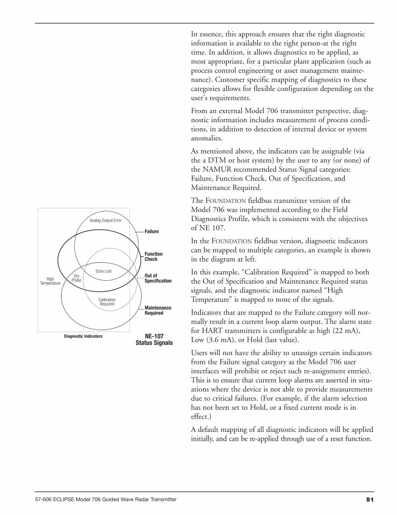
5157-606 ECLIPSE Model 706 Guided Wave Radar Transmitter
In essence, this approach ensures that the right diagnosticinformation is available to the right person-at the righttime. In addition, it allows diagnostics to be applied, asmost appropriate, for a particular plant application (such asprocess control engineering or asset management mainte-nance). Customer specific mapping of diagnostics to thesecategories allows for flexible configuration depending on theuser's requirements.
From an external Model 706 transmitter perspective, diag-nostic information includes measurement of process condi-tions, in addition to detection of internal device or systemanomalies.
As mentioned above, the indicators can be assignable (viathe a DTM or host system) by the user to any (or none) ofthe NAMUR recommended Status Signal categories:Failure, Function Check, Out of Specification, andMaintenance Required.
The FOUNDATION fieldbus transmitter version of theModel 706 was implemented according to the FieldDiagnostics Profile, which is consistent with the objectivesof NE 107.
In the FOUNDATION fieldbus version, diagnostic indicatorscan be mapped to multiple categories, an example is shownin the diagram at left.
In this example, “Calibration Required” is mapped to boththe Out of Specification and Maintenance Required statussignals, and the diagnostic indicator named “HighTemperature” is mapped to none of the signals.
Indicators that are mapped to the Failure category will nor-mally result in a current loop alarm output. The alarm statefor HART transmitters is configurable as high (22 mA),Low (3.6 mA), or Hold (last value).
Users will not have the ability to unassign certain indicatorsfrom the Failure signal category as the Model 706 userinterfaces will prohibit or reject such re-assignment entries).This is to ensure that current loop alarms are asserted in situ-ations where the device is not able to provide measurementsdue to critical failures. (For example, if the alarm selectionhas not been set to Hold, or a fixed current mode is ineffect.)
A default mapping of all diagnostic indicators will be appliedinitially, and can be re-applied through use of a reset function.
Analog Output Error
Echo Lost
CalibrationRequired
Failure
FunctionCheck
Out ofSpecification
MaintenanceRequired
NE-107Status Signals
Diagnostic Indicators
HighTemperature
DryProbe

52 57-606 ECLIPSE Model 706 Guided Wave Radar Transmitter
Refer to the table below for a complete listing of theModel 706 diagnostic indicators, along with their explana-tions, default categories, and recommended remedies.
NOTES: 1) The remedies shown in this table can also be seen on the transmitter LCD by viewing the present status screen when the device is in a diagnostic condition.
2) Those indicators showing failure as the default result in an alarm condition.
3.3.2 Diagnostic Indication Simulation
The DD and DTM allow for the ability to manipulatediagnostic indicators. Intended as a means to verify theconfiguration of the diagnostic parameters and connectedequipment, a user can manually change any indicator toand from the active state.
3.3.3 Diagnostic Indicator Table
Below is a listing of the Model 706 diagnostic indicators,showing their priority, explanations and recommendedremedies. (Priority 1 is highest priority.)
Priority Indicator NameDefaultCategory
Explanation Remedy (Context Sensitive Help)
1 Software Error FailureUnrecoverable error occurred in storedprogram.
Contact MAGNETROL Technical Support.
2 RAM Error Failure RAM (read/write) memory failing.
3 ADC Error Failure Analog-to-digital converter failure.
4 EEPROM Error Failure Non-volatile parameter storage failing.
5 Analog Board Error Failure Unrecoverable hardware failure.
6Analog Output
ErrorFailure
Actual loop current deviates fromcommanded value. Analog output isinaccurate.
Perform Adjust Analog Outputmaintenance procedure.
7 Spare Indicator 1 OK Reserved for future use.
8 Default ParametersSaved parameters are set to defaultvalues.
Perform complete Device Configuration.
9 No Probe Failure No Probe Connected.
Attach a probe.Torque HF nut.Clean gold pin on transmitter and socketon probe.Contact MAGNETROL Technical Support.
10 No Fiducial Failure Reference signal too weak to detect.
Torque HF nut.Clean gold pin on transmitter and socketon probe.Check settings:
Fiducial GainHF Cable LengthWindow
Increase Fid Gain.Contact MAGNETROLTechnical Support.

5357-606 ECLIPSE Model 706 Guided Wave Radar Transmitter
3.3.3 Diagnostic Indicator Table
Priority Indicator NameDefaultCategory
Explanation Remedy
11 No Echoes Failure No signal detected anywhere on probe.
Check settings:Dielectric RangeSensitivityEoP Thresh Value
Increase Sensitivity.Lower EoP Thresh.View Echo Curve.
12 Upr Echo Lost FailureSignal from upper liquid too weak todetect.
Check settings:Upper Dielectric,Blocking Distance,Sensitivity
Ensure Upr Level is below blockingdistance.View Echo Curve.
13 Spare Indicator 2 OK Reserved for future use.
14 EoP Above ProbeEnd FailureEnd of Probe appears above ProbeLength
Check settings:Probe LengthDecrease SensitivityIncrease Blocking Distance
View Echo Curve.
15 Lvl Below ProbeEnd FailureLevel signal appears beyond ProbeLength.(Possible water bottom situation)
Check settings:Probe Model,Probe Length,Level Threshold = FixedIncrease Sensitivity
View Echo Curve.
16 EoP Below ProbeEnd FailureEnd of Probe appears beyond ProbeLength.
Check settings:Probe LengthDielectric RangeSensitivity
View Echo Curve.
17 Safety Zone Alarm FailureRisk of echo loss if liquid rises aboveBlocking Distance.
Ensure that liquid cannot reachBlocking Distance.
18 Config Conflict FailureMeasurement type and primary variableselection parameters are inconsistent.
Confirm proper configuration. Check Measurement Type.
19 High Volume Alarm FailureVolume calculated from Level readingexceeds capacity of vessel or customtable.
Check settings:Vessel Dimensions,Custom Table entries
20 High Flow Alarm FailureFlow calculated from Distance readingexceeds capacity of flow element orcustom table.
Check settings:Flow ElementReference DistanceGen Eqn FactorsCustom Table entries
21 Spare Indicator 3 OK Reserved for future use
22 InitializingFunctionCheck
Distance measurement is inaccuratewhile internal filters are settling.
Standard start-up message. Wait for upto 10 seconds.
23Analog Output
FixedFunctionCheck
Loop current not following PV. May becaused by existing alarm condition, ongoingLoop Test or Trim Loop operations.
If unexpected, check Loop CurrentMode. Ensure device is not in LoopTest.
24 Config ChangedFunctionCheck
A parameter has been modified from theUser Interface.
If desired, reset Config Changedindicator in ADVANCED CONFIG menu.

54 57-606 ECLIPSE Model 706 Guided Wave Radar Transmitter
3.3.3 Diagnostic Indicator Table
Priority Indicator NameDefaultCategory
Explanation Remedy
25 Spare Indicator 4 OK Reserved for future use.
26 Spare Indicator 5 OK Reserved for future use.
27Ramp Interval
ErrorOut of Spec
Internal signal timing out of limits causinginaccurate distance measurement.
Check accuracy of Level reading.Replace transmitter electronics.Contact MAGNETROL Technical Support.
28 High Elec Temp Out of SpecElectronics too hot. May compromiselevel measurement or damageinstrument.
Shield transmitter from heat source orincrease air circulation. Locatetransmitter remotely in a cooler area.
29 Low Elec Temp Out of SpecElectronics too cold. May compromiselevel measurement or damageinstrument.
Insulate transmitter.Locate transmitter remotely in a coolerarea.
30 Calibration Req’d Out of SpecFactory calibration has been lost.Measurement accuracy may bediminished.
Return transmitter to factory forrecalibration.
31Echo RejectInvalid
Out of SpecEcho Rejection inoperative. May reporterroneous Level readings. Upr Echomay be lost near top of probe.
Save a fresh Echo Rejection Curve.
32 Inferred Level Out of SpecDistance measurement calculatedindirectly from probe elongation. Levelreading is only approximate.
Verify Level reading. If incorrect,compare Dielectric Range against EoPDielectric reading.
33 Adjust Analog Out Out of Spec Loop current is inaccurate.Perform Adust Analog Outputmaintenance procedure.
34Totalizer Data
LostOut of Spec
Non-volatile Totalizer Data storagefailing.
Contact MAGNETROL TechnicalSupport.
35 No Probe Target Out of Spec Not actively compensatingCheck settings:
Probe ModelSensitivity
36 Low Supply Voltage Out of SpecLoop current may be incorrect athigher values. Analog output isinaccurate.
Verify loop resistance.Replace loop power supply.
37 Dry Probe OKNo liquid is contacting probe. Level atunknown distance beyond probe.
If unexpected, verify proper probelength for application.
38 Spare Indicator 6 OK Reserved for future use.
39 Low Echo StrengthMaintenanceRequired
Risk of Echo Lost due to weak signal.
Check settings:Dielectric RangeSensitivity
View Echo Curve.
40 Low Ifc Echo StrMaintenanceRequired
Risk of Interface Echo Lost due toweak signal.
Check settings:Dielectric RangeSensitivity
View Echo Curve.
41 Spare Indicator 7 OK Reserved for future use.
42 Sequence Record OKA Sequence Record number has beenstored in Event Log.
If desired, report Sequence Recordnumber to factory.
The ECLIPSE Model 706 offers the ability to do Trending and Echo Curve analysis via the local graphical LCD or by using PACTware and the Model 706 DTM.The Model 706 DTM is a power troubleshooting tool that can aid in the resolution of some of the Diagnostic Indicators shown above.

5557-606 ECLIPSE Model 706 Guided Wave Radar Transmitter
3.3.4 Diagnostic Help
Selecting DIAGNOSTICS from the MAIN MENUpresents a list of five ITEMS from the top level of theDIAGNOSTICS tree.
When Present Status is highlighted, the highestMAGNETROL priority active diagnostic indicator (numer-ically lowest in Table 3.3.3) is displayed on the bottomLCD line as shown above. Pressing the ENTER key movesthe active diagnostic indicator tothe top line outdented and presents in the lower area of theLCD a brief explanation of and possible remedies for theindicated condition. A blank line separates the explanationfrom the remedies. Additional active diagnostic indicators,if any, appear with their explanations in descending priorityorder. Each additional active indicator name-explanationpair is separated by a blank line from the one above.
If the explanation and remedy text (and additional name-explanation pairs) exceeds the available space, a appearsin the rightmost column of the last line indicating more textbelow. In this situation, the DN key scrolls text up one lineat a time. Similarly, while text exists above the upper line ofthe text field, a appears in the rightmost column of thetop (text) line. In this situation, the UP key scrolls the textdown one line at a time. Otherwise the DN and UP keysare inoperative. In all cases the ENT or DEL key reverts tothe previous screen.
When the transmitter is operating normally and the high-light cursor is positioned on Present Status, the bottomLCD line displays “OK” because no diagnostic indicatorsare active.
EVENT HISTORY – This menu displays the parametersrelated to diagnostic event logging.
ADVANCED DIAGNOSTICS – This menu displays para-meters related to some of the advanced diagnostics availablewithin the Model 706.
INTERNAL VALUES – Displays read-only internalparameters.
ELEC TEMPERATURES – Displays temperature information as measured in the potted module in degrees F or C.
TRANSMITTER TESTS – Allows the user to manually set the output current to a constant value.This is a method for the user to verify operation of theother equipment in the loop.
ECHO CURVES – This menu allows the user to displaythe live Echo Curve and Echo Rejection on the LCD.

56 57-606 ECLIPSE Model 706 Guided Wave Radar Transmitter
ECHO HISTORY SETUP – The Model 706 contains theunique and powerful feature that allows waveforms to beautomatically captured based on Diagnostic Events, Time orboth. This menu contains those parameters that configurethat feature.
Eleven (11) waveforms can be saved directly into the trans-mitter.
• Nine (9) Troubleshooting Curves
• One (1) Echo Rejection Curve
• One (1) Reference Curve
TREND DATA – A 15-minute trend of the PV can bedisplayed on the LCD.
3.3.5 Troubleshooting Application Issues
There can be numerous reasons for application-relatedissues. Media buildup on the probe is covered here.
Media buildup on the probe is typically not a problem inmost cases—ECLIPSE circuitry works very effectively.Media buildup should be viewed as two types:
• Continuous Film Coating
• Bridging
3.3.5.1 Model 706 (Dual Element Coaxial or Twin Rod probe)
Continuous Film Coating
One type of potential application problem is when themedia forms a continuous coating on the probe. Althoughthe ECLIPSE Model 706 will continue to measure effectively,some small inaccuracies may occur as the signal propagationis affected by the thickness, length, and dielectric constantof the coating.
It is a very rare case where filming causes a noticeable per-formance degradation.
Bridging
A more common coating problem occurs when the processmedium is viscous or solid enough to actually clog, orbridge, between the elements. This bridging can cause anoticeable degradation in performance. For example, highdielectric media (e.g., water-based) can be detected as levelat the location of the bridging.
Similarly, a problem can develop if the product begins tobuild up on the spacers that separate the coaxial probe ele-ments. High dielectric media (e.g., water-based) will causethe greatest error.
FilmCoating
Bridging

5757-606 ECLIPSE Model 706 Guided Wave Radar Transmitter
Single rod GWR probes are typically the best probes forapplications with potential buildup, but other factors in theapplication must be considered (such as mounting, sensitivi-ty, etc). For this reason, the ECLIPSE Model 706 is offeredwith a variety of coaxial, single rod, and Twin Flexibleprobes so the correct probe can be used for the givenapplication.
Refer to Section 3.6.4 for viscosity specifications on thevarious ECLIPSE probes.
Contact the factory for any questions regardingapplications with potential coating and buildup.
3.3.5.2 Model 706 (Single Rod Probe)
The Model 706 and Single Rod probe were designed tooperate effectively in the presence of media building up.Some expected error may be generated based upon thefollowing factors:
1. Dielectric of the media that created the coating
2. Thickness of the coating
3. Amount (length) of the coating above the present level
Although more immune to thick, viscous, buildup, perfor-mance of Single Rod GWR probes is always dependent onthe installation and application. The electromagnetic fieldsurrounding a single rod probe makes it more vulnerable toinfluence from objects in the vicinity of the probe.
NOTE: It is important to note that this influence from the installa-tion/application also depends on the configuration of the trans-mitter. Those devices configured with lower gain will be lessaffected by external objects.
Nozzles
Due to the impedance mismatch that takes place at the endof a nozzle, they can create false echoes that can cause diag-nostic indicators and/or errors in measurement.
As mentioned above, by virtue of the pure physics of thetechnology, all single rod GWR probes are influenced bythe application and installation. Mismatches in impedancealong the length of the probe, whether they be expected(liquid level) or unexpected (metal in close proximity), willresult in reflections.
To better illustrate this, a comparison between a coaxialprobe and single rod probe mounted in the same applicationis shown at left.
Process Seal isFully Transparent
Coaxial Probe
Large ImpedanceMismatch
Standard Single Rod Probe
Coating Buildup

58 57-606 ECLIPSE Model 706 Guided Wave Radar Transmitter
Since the outer tube of the coaxial probe is grounded, thereare no proximity affects and there is no influence from thenozzle. The only reflections along the length of the probeare expected. Those being the fiducial (reference signal) andthe return signal from the process.
On the other hand, a single rod probe mounted in the exactsame nozzle will have additional (unwanted) reflectionswhere the probe enters and exits the nozzle. These reflec-tions are a result of the impedance changes that occur atthose points:
• The large reflection is due to the impedance developedbetween the rod and nozzle ID as compared to the imped-ance developed between the rod and the tank ID. (The larg-er the nozzle ID, the smaller the reflection).
One way to eliminate the reflection at the bottom of thenozzle is to use a continuous stillwell in conjunction with acaged GWR probe. In doing so, there will be no impedancechanges all the way down the probe.
Refer to Section 3.2.6 for a discussion on overfill-capableprobes for suggestions on how to eliminate these unwantedsingle rod reflections. MAGNETROL is unique in the factthat we offer a special caged probe that, when installedproperly, has no unwanted reflections.
Obstructions
Metallic obstructions in the vicinity of a single rod probecan also affect the performance. If the level reading repeat-edly locks on to a specific level higher than the actual level,it may be caused by a metallic obstruction. Obstructions inthe vessel (e.g., pipes, ladders) that are located close to theprobe may cause the instrument to show them as level.
Refer to the Probe Clearance Table for recommended clear-ance distances. The distances shown in this table can be dra-matically reduced by utilizing the Echo Rejection feature(within the transmitter or) in PACTware and the ECLIPSEModel 706 DTM.
NOTE: Use caution when rejecting large positive going signals as thenegative going level signal can be lost when passing throughthem.
PROBE CLEARANCE TABLE
Mismatch Dependson Mounting
Single Rod Probe in a Stillwell
Caged Probe(waveform is similar to that of a coaxial probe)
Obstruction
Nozzles• 2" Diameter minimum• Ratio of Diameter: Length should be >1:1• Do not use Pipe Reducers (restriction)
Distanceto Probe
Acceptable Objects
<6" Continuous, smooth, parallel conductive surface, for example a metal tank wall;important that probe does not touch wall
>6" <1" (25mm) diameter pipe and beams, ladder rungs
>12" <3" (75mm) diameter pipe and beams, concrete walls
>18" All remaining objects

5957-606 ECLIPSE Model 706 Guided Wave Radar Transmitter
3.4 Configuration Information
This section is intended to offer additional configuration-related details with respect to some of the parametersshown in the Menu in Section 2.6.
3.4.1 Level Offset Description
The parameter referred to as Level Offset in the ECLIPSEModel 706 DEVICE SETUP/BASIC CONFIG menu isdefined as the desired level reading when liquid surface isat the tip of the probe.
The ECLIPSE Model 706 transmitter is shipped from thefactory with Level Offset set to 0. With this configuration,all measurements are referenced from the bottom of theprobe. See Example 1.
Example 1 (Level Offset = 0 as shipped from factory):
Application calls for a 72-inch Model 7yT coaxial probewith an NPT process connection. The process medium iswater with the bottom of the probe 10 inches above thebottom of the tank.
The user wants the 4 mA Set Point (LRV) at 24 inchesand the 20 mA Set Point (URV) at 60 inches as referenced from the bottom of the probe.
In those applications in which it is desired to reference allmeasurements from the bottom of the vessel, the value ofLevel Offset should be changed to the distance between thebottom of the probe and the bottom of the vessel as shownin Example 2.
Example 2:
Application calls for a 72-inch Model 7yT coaxial probewith an NPT process connection. The process medium iswater with the bottom of the probe 10 inches above thebottom of the tank.
The user wants the 4 mA Set Point (LRV) at 24 inchesand the 20 mA Set Point (URV) at 60 inches as referenced from the bottom of the tank.
When the ECLIPSE transmitter is mounted in a cham-ber/bridle, it is usually desirable to configure the unit withthe 4 mA Set Point (LRV) at the lower process connectionand the 20 mA Set Point (URV) at the upper process connection. The measuring range then becomes the center-to-center dimension. In this case, a negative Level Offsetneeds to be entered. In doing so, all measurements are thenreferenced at a point up on the probe, as shown inExample 3.
10"
60"
20 mA
4 mA
24"
Level Units = inches
Probe Model = 7YT
Probe Mount = NPT
Probe Length = 72 in
Level Offset = 0 in
Dielectric Range =Above 10
4 mA = 24 in
20 mA = 60 in
Example 1
10"
60"
20 mA
4 mA
24"
Level Units = inches
Probe Model = 7YT
Probe Mount = NPT
Probe Length = 72 in
Level Offset = 10 in
Dielectric Range =Above 10
4 mA = 24 in
20 mA = 60 in
Example 2

60 57-606 ECLIPSE Model 706 Guided Wave Radar Transmitter
Example 3:
Application calls for a 48-inch Model 7yG caged-coaxialflanged probe measuring water in a chamber with thebottom of the probe extending 6 inches below the lowerprocess connection. The user wants the 4 mA point tobe 0 inches at the bottom process connection and the20 mA point to be 30 inches at the top process connection.
3.4.2 End-of-Probe Analysis
A new addition to the Model 706 ECLIPSE transmitter is afeature called End-of-Probe Analysis (EoPA).
Located in the DEVICE SETUP/ADVANCED CONFIGMenu, this feature is patterned after the “Tank-BottomFollowing” algorithms of the early Non-Contact radartransmitters. When the return signal from the level is lost,this feature allows the Model 706 transmitter to infer levelmeasurement based on the apparent location of the end-of-probe (EoP) signal.
Due to the fact that the propagation of the GWR signal isaffected by the dielectric constant of the medium in whichit is traveling, signals along the probe are delayed in propor-tion to the dielectric constant. By monitoring the locationof the (delayed) EoP signal and knowing the dielectric con-stant of the medium, the level signal can be back-calculated,or inferred.
The End-of-Probe Analysis feature is located in theAdvanced Config menu and requires an Advanced Passwordto activate. Several additional parameters will need to beconfigured for optimum performance.
NOTE: The accuracy of this level measurement mode is not that ofdetecting true product level, and can vary depending on theprocess. MAGNETROL recommends that this feature be usedonly as last resort for measuring levels in those rare applica-tions in which the level signals are inadequate, even after thecommon troubleshooting techniques of gain increase andthreshold adjustment are implemented.
Contact MAGNETROL Technical Support for additionalinstructions.
6"
30"
4 mA
20 mA
Level Units = inches
Probe Model = 7YG
Probe Mount = Flange
Probe Length = 48 in
Level Offset =-6.0 in
Dielectric Range =Above 10
4 mA = 0in
20 mA = 30 in
Example 3

3.4.3 Echo Rejection
Due to the fact that GWR transmitters are less susceptibleto obstructions in a vessel (as compared with Non-ContactRadar transmitters) , early versions of the ECLIPSE Model705 transmitters did not have Echo Rejection capability.
However, due to our vast experience in the field, we havefound that there are (albeit rare) occasions when it is desir-able to have the ability to “ignore” unwanted signals alongthe probe.
The Model 706 transmitter Echo Rejection feature islocated in the DEVICE SETUP/ADVANCED CONFIGmenu, and requires an Advanced Password to activate. It ishighly recommended that this feature be used with thewaveform capture capability of the Model 706 DTM andPACTware™.
Contact MAGNETROL Technical Support for additionalinstructions.
3.4.4 Volumetric Capability
Selecting Measurement Type = Volume and Level allows theModel 706 transmitter to measure volume as the PrimaryMeasured Value.
3.4.4.1 Configuration using built-in Vessel Types
The following table provides an explanation of each of theSystem Configuration parameters required for volume appli-cations that use one of the nine Vessel Types.
6157-606 ECLIPSE Model 706 Guided Wave Radar Transmitter
Configuration Parameter Explanation
Volume UnitsA selection of Gallons (factory default Volume Unit), Milliliters, Liters, Cubic Feet, or CubicInches, is provided.
Vessel Type
Select either Vertical/Flat (factory default Vessel Type), Vertical/Elliptical, Vertical/Spherical,Vertical/Conical, Custom Table, Rectangular, Horizontal/Flat, Horizontal/Elliptical,Horizontal/Spherical, or Spherical.
Note: Vessel Dims is the next screen only if a specific Vessel Type was selected. If Custom Tablewas selected. Refer to page 61 to select the Cust Table Type and Cust Table Vals.
Vessel Dims See the vessel drawings on the following page for relevant measuring areas.
Radius Used for all Vessel Types with the exception of Rectangular.
Ellipse Depth Used for Horizontal and Vertical/Elliptical vessels.
Conical Height Used for Vertical/Conical vessels.
Width Used for Rectangular vessels.
Length Used for Rectangular and Horizontal vessels.

62 57-606 ECLIPSE Model 706 Guided Wave Radar Transmitter
SPHERICAL
HORIZONTAL/SPHERICAL
Vessel Types
VERTICAL/FLAT VERTICAL/CONICAL
HORIZONTAL/FLAT
RECTANGULAR
HORIZONTAL/ELLIPTICAL
VERTICAL/ELLIPTICAL VERTICAL/SPHERICAL

3.4.4.2 Configuration using Custom Table
If none of the nine Vessel Types shown can be used, aCustom Table can be created. A maximum of 30 points canbe used to establish the level to volume relationship. Thefollowing table provides an explanation of each of theSystem Configuration parameters for volume applicationswhere a Custom Table is needed.
6357-606 ECLIPSE Model 706 Guided Wave Radar Transmitter
Configuration Parameter Explanation (Custom Volumetric Table)
Volume UnitsA selection of Gallons (factory default Volume Unit), Milliliters, Liters, CubicFeet, or Cubic Inches, is provided.
Vessel Type Select Custom Table if none of the nine Vessel Types can be used.
Cust Table TypeThe Custom Table points can be a Linear (straight line between adjacent points) orSpline (can be a curved line between points) relationship. See below drawing formore information.
Cust Table Vals
A maximum of 30 points can be used in building the Custom Table. Each pair ofvalues will have a level (height) in the units chosen in the Level Units screen, andthe associated volume for that level point. The values must be monotonic, i.e.each pair of values must be greater than the previous level/volume pair. The lastpair of values should have the highest level value and volume value associatedwith the level in the vessel.
LINEAR SPLINE
P2
P1
P1 P2P3
P4
P5P6P7
P8P9
Transition point
Use where walls are not perpendicular to base.
Concentrate at least two points at beginning (P1) and end (P9);and three points at either side of transition points.

64 57-606 ECLIPSE Model 706 Guided Wave Radar Transmitter
3.4.5 Open Channel Flow Capability
Selecting Measurement Type = Flow allows the Model 706transmitter to measure flow as the Primary Measured Value.
Open channel flow is performed by using the ECLIPSEModel 706 to measure the Head in a hydraulic structure.The hydraulic structure is the primary measuring element,of which the two most common types are weirs and flumes.
Since the primary element has a defined shape and dimen-sions, the rate of flow through the flume or over the weir isrelated to the Head at a specified measurement location.
The ECLIPSE Model 706 is the secondary measuringdevice, which measures the Head of the liquid in the flumeor weir. Open channel flow equations stored in the trans-mitter firmware convert the measured Head into units offlow (volume/time).
NOTE: Proper positioning of the Model 706 should be per the recom-mendation of the flume or weir manufacturer.
Model 706
Flow
ParshallFlume
Open Channel Flow MeasurementParshall Flume
Model706
Flow
Water SurfaceThroat Section
Head
Blocking Distance10" (250 mm) min.
Ref
eren
ceD
ista
nce
Head
Crest
Channel Floor
Blo
ckin
gD
ista
nce
10"
(250
mm
)m
inim
um
Weir Plate
Water Surface
ReferenceDistance
Model706
Flume (side view)
Weir (side view)

3.4.5.1 Configuration using Flume/Weir Equations
The following table provides an explanation of each of theSystem Configuration parameters required for open channelflow applications using one of the Flow Elements that arestored in the firmware.
6557-606 ECLIPSE Model 706 Guided Wave Radar Transmitter
Configuration Parameter Explanation
Flow UnitsA selection of Gallons/Minute (factory default Flow Unit), Gallons/Hour, MilGallons/Day, Liters/Second, Liters/Minute, Liters/Hour, Cubic Meter/Hour,Cubic Ft/Second, Cubic Ft/Minute, and Cubic Ft/Hour are provided.
Flow Element
Select one of the following primary Flow Elements that are stored in the firmware:Parshall flume sizes of 1", 2", 3", 6", 9", 12", 18", 24", 36", 48", 60", 72", 96",120" and 144". Palmer-Bwls (Palmer-Bowlus) flume sizes of 4", 6", 8", 10", 12",15", 18", 21", 24", 27" and 30". V-notch weir sizes of 22.5O, 30O, 45O, 60O, 90O and120O. Rect with Ends (Rectangular Weir with End Contractions), Rect w/o Ends(Rectangular Weir without End Contractions), and Cipoletti weir. Custom Table (seepage 65 can be selected if none of the stored Flow Elements can be used. Thetable can be built with a maximum of 30 points. The Model 706 also has the capa-bility of using a Generic Equation (see page 26) for flow calculation.
Weir Crest LengthThe Weir Crest Length screen only appears when the chosen Flow Element isCipoletti or one of the Rectangular weirs. Input this length in the user-selectedlevel units.
Flume Channel Width Allows for entry of the width of the palmer bowlus flume.
V-Notch Weir AngleOnly appears when flow element is V-Notch weir. It allows for the entry of angle ofthe V-Notch weir.
Reference DistThe Reference Distance is measured from the sensor reference point to the pointof zero flow in the weir or flume. This must be measured very accurately in theuser-selected level units.
Maximum Head
Maximum Head is the highest liquid level (Head) value in the flume or weir beforethe flow equation is no longer valid. The Maximum Head is expressed in the user-selected Level Units. The Model 706 will default to the largest Maximum Head valuethat is allowed for any given flume or weir. The Maximum Head value can be reviseddepending on the value of the Reference Distance, or for end user preference.
Maximum FlowMaximum Flow is a read-only value that represents the flow value correspondingto the Maximum Head value for the flume or weir.
Low Flow CutoffThe Low Flow Cutoff (in user-selected level units) will force the calculated flowvalue to zero whenever the Head is below this point. This parameter will have adefault and minimum value of zero.
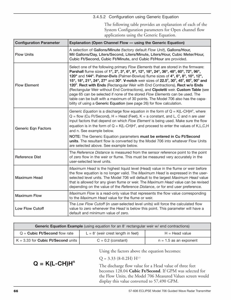
66 57-606 ECLIPSE Model 706 Guided Wave Radar Transmitter
3.4.5.2 Configuration using Generic Equation
The following table provides an explanation of each of theSystem Configuration parameters for Open channel flowapplications using the Generic Equation.
Configuration Parameter Explanation (Open Channel Flow — using the Generic Equation)
Flow UnitsA selection of Gallons/Minute (factory default Flow Unit), Gallons/Hour,Mil Gallons/Day, Liters/Second, Liters/Minute, Liters/Hour, Cubic Meter/Hour,Cubic Ft/Second, Cubic Ft/Minute, and Cubic Ft/Hour are provided.
Flow Element
Select one of the following primary Flow Elements that are stored in the firmware:Parshall flume sizes of 1", 2", 3", 6", 9", 12", 18", 24", 36", 48", 60", 72", 96",120" and 144". Palmer-Bwls (Palmer-Bowlus) flume sizes of 4", 6", 8", 10", 12",15", 18", 21", 24", 27" and 30". V-notch weir sizes of 22.5O, 30O, 45O, 60O, 90O and120O. Rect with Ends (Rectangular Weir with End Contractions), Rect w/o Ends(Rectangular Weir without End Contractions), and Cipoletti weir. Custom Table (seepage 65 can be selected if none of the stored Flow Elements can be used. Thetable can be built with a maximum of 30 points. The Model 706 also has the capa-bility of using a Generic Equation (see page 26) for flow calculation.
Generic Eqn Factors
Generic Equation is a discharge flow equation in the form of Q = K(L-CH)Hn, whereQ = flow (Cu Ft/Second), H = Head (Feet), K = a constant, and L, C and n are userinput factors that depend on which Flow Element is being used. Make sure the flowequation is in the form of Q = K(L-CH)Hn, and proceed to enter the values of K,L,C,Hand n. See example below.
NOTE: The Generic Equation parameters must be entered in Cu Ft/Secondunits. The resultant flow is converted by the Model 706 into whatever Flow Unitsare selected above. See example below.
Reference DistThe Reference Distance is measured from the sensor reference point to the pointof zero flow in the weir or flume. This must be measured very accurately in theuser-selected level units.
Maximum Head
Maximum Head is the highest liquid level (Head) value in the flume or weir beforethe flow equation is no longer valid. The Maximum Head is expressed in the user-selected level units. The Model 706 will default to the largest Maximum Head valuethat is allowed for any given flume or weir. The Maximum Head value can be reviseddepending on the value of the Reference Distance, or for end user preference.
Maximum FlowMaximum Flow is a read-only value that represents the flow value correspondingto the Maximum Head value for the flume or weir.
Low Flow CutoffThe Low Flow Cutoff (in user-selected level units) will force the calculated flowvalue to zero whenever the Head is below this point. This parameter will have adefault and minimum value of zero.
Using the factors above the equation becomes:
Q = 3.33 (8-0.2H) H1.5
The discharge flow value for a Head value of three feetbecomes 128.04 Cubic Ft/Second. If GPM was selected forthe Flow Units, the Model 706 Measured Values screen woulddisplay this value converted to 57,490 GPM.
Generic Equation Example (using equation for an 8' rectangular weir w/ end contractions)
Q = Cubic Ft/Second flow rate L = 8' (weir crest length in feet) H = Head value
K = 3.33 for Cubic Ft/Second units C = 0.2 (constant) n = 1.5 as an exponent
Q = K(L-CH)Hn

3.4.5.3 Configuration using Custom Table
The following table provides an explanation of each of theSystem Configuration parameters for open channel flowapplications using the Custom Table.
6757-606 ECLIPSE Model 706 Guided Wave Radar Transmitter
SPLINE OR LINEAR
SPLINE P1P2
P3
P4
P5
Concentrate points along curve
P2
P3
P7
P10Transition point
P1
Concentrate points as follows:A. At least two points at beginning (P1 and P2); B. At least two points at end (P9 and P10); C. Three points at approximate average flow rate (for example, P3, P4, P5); and at transition point (P7) and points on either side (P6, P8).
P5P4
P6
P8
P9
Average flow rate
Configuration Parameter Explanation (Open Channel Flow — Custom Table)
Flow UnitsA selection of Gallons/Minute (factory default Flow Unit), Gallons/Hour,Mil Gallons/Day, Liters/Second, Liters/Minute, Liters/Hour, Cubic Meters/Hour,Cubic Ft/Second, Cubic Ft/Minute, and Cubic Ft/Hour are provided.
Flow Element
Select one of the following primary Flow Elements that are stored in the firmware:Parshall flume sizes of 1", 2", 3", 6", 9", 12", 18", 24", 36", 48", 60", 72", 96",120" and 144". Palmer-Bwls (Palmer-Bowlus) flume sizes of 4", 6", 8", 10", 12",15", 18", 21", 24", 27" and 30". V-notch weir sizes of 22.5O, 30O, 45O, 60O, 90O and120O. Rect with Ends (Rectangular Weir with End Contractions), Rect w/o Ends(Rectangular Weir without End Contractions), and Cipoletti weir. Custom Table (seepage 65 can be selected if none of the stored Flow Elements can be used. Thetable can be built with a maximum of 30 points. The Model 706 also has the capa-bility of using a Generic Equation (see page 66) for flow calculation.
Custom TableThe Custom Table points can be a Linear (straight line between adjacent points) orSpline (can be a curved line between points) relationship. Refer to the drawingabove for more information.
Cust Table Vals
A maximum of 30 points can be used in building the Custom Table. Each pair of val-ues will have a Head (height) in the units chosen in the Level Units screen, and theassociated flow for that Head value. The values must be monotonic, i.e., each pairof values must be greater than the previous Head/flow pair. The last pair of valuesshould have the highest Head value (usually the Maximum Head value) and the flowassociated with that Head value.
Reference DistThe Reference Distance is measured from the sensor reference point to the pointof zero flow in the weir or flume. This must be measured very accurately in theuser-selected level units.
Maximum Head
Maximum Head is the highest liquid level (Head) value in the flume or weir beforethe flow equation is no longer valid. The Maximum Head is expressed in the user-selected Level Units. The Model 706 will default to the largest Maximum Head valuethat is allowed for any given flume or weir. The Maximum Head value can be reviseddepending on the value of the Reference Distance, or for end user preference.
Maximum FlowMaximum Flow is a read-only value that represents the flow value correspondingto the Maximum Head value for the flume or weir.
Low Flow CutoffThe Low Flow Cutoff (in user-selected level units) will force the calculated flowvalue to zero whenever the Head is below this point. This parameter will have adefault and minimum value of zero.

68 57-606 ECLIPSE Model 706 Guided Wave Radar Transmitter
3.4.6 Reset Function
A parameter labeled “Reset Parameter” is located at the endof the DEVICE SETUP/ADVANCED CONFIG menu.In the event a user gets confused during configuration oradvanced troubleshooting, this parameter gives the user theability to reset the Model 706 transmitter configuration.
Unique to the Model 706 transmitter is the ability forMAGNETROL to fully “pre-configure” devices to customerrequests. For that reason, the Reset function will return thedevice back to the state at which it left the factory.
It is recommended that MAGNETROL Technical Supportbe contacted as the Advanced User password will berequired for this reset.
3.4.7 Additional Diagnostic/Troubleshooting Capabilities
3.4.7.1 Event History
As a means for improved troubleshooting capability, arecord of significant diagnostic events is stored with timeand date stamps. A real time on board clock (which must beset by the operator), will maintain the current time.
3.4.7.2 Context-sensitive Help
Descriptive information relevant to the highlighted parameterin the menu will be accessible via the local display andremote host interfaces. This will most often be a parameter-related screen, but could also be information about menus,actions (for example, Loop [Analog Output] Test, resets ofvarious types), diagnostic indicators, etc.
For example: Dielectric Range — Selects the range boundingthe dielectric constant of the medium in vessel. For interfacemeasurement mode, it selects the range bounding thedielectric constant of the lower liquid medium. Some rangesmay not be selectable depending on the probe model.
3.4.7.3 Trend Data
Another new feature to the Model 706 is the the ability tolog several measured values (selectable from any of theprimary, secondary, or supplemental measured values) at aconfigurable rate (for example, once every five minutes) fora period ranging from several hours to a number of days(depending on the configured sample rate and number ofvalues to be recorded). The data will be stored in non-volatile memory in the transmitter with date and timeinformation for subsequent retrieval and visualization usingthe associated Model 706 DTM.

6957-606 ECLIPSE Model 706 Guided Wave Radar Transmitter
3.5 Agency Approvals
3.5.1 Agency Specifications – Explosion Proof InstallationFactory Sealed: This product has been approved by Factory Mutual Research (FM) and Canadian StandardsAssociation (CSA) as a Factory Sealed device.NOTE: Factory Sealed: No Explosion Proof conduit fitting (EY seal) is required within 18" of the transmitter. However, anExplosion Proof conduit fitting (EY seal) is required between the hazardous and safe areas.
FM 706-51XX-1XX Intrinsically Safe Class I, Div. 1; Groups A, B, C, & DClass II, Div. 1; Groups E, F, & G T4Class III, Type 4X, IP67Entity
706-51XX-3XX Explosion-proof Class I, Div. 1; Groups B, C & D(with Intrinsically Safe probe)Dust Ignition-proof Class II, Div. 1; Groups E, F, & G T4
Class III, Type 4X, IP67706-51XX-XXX Non-Incendive, Suitable for: Class I, Div. 2; Groups A, B, C, & D
Class II, Div. 2; Groups E, F & G T4Class III, Type 4X, IP67
CSA 706-51XX-1XX Intrinsically Safe Class I, Div. 1; Groups A, B, C, & DClass II, Div. 1; Group E, F & G T4Class III, Type 4X, IP66/67Entity
706-51XX-3XX Explosion-proof Class I, Div. 1; Groups B, C, & D(with Intrinsically Safe probe)Dust Ignition-proof Class II, Div. 1; Group E, F & G T4
Class III, Type 4X, IP66/67706-51XX-XXX Non-Incendive Class I, Div. 2; Groups A, B, C, & D
Suitable for: Class II, Div. 2; Group E, F & G T4Class III, Type 4X, IP66/67
ATEX 706-51XX-AXX Intrinsically Safe II 1G, Ex ia IIC T4
706-51XX-CXX Non-sparking II 1/3 G Ex nA [ia Ga] IIC T4 Ga/Gc
706-51XX-DXX Dust Ex II 1/2 Ex tb [ia] IIIC T85°C .. T450°C Db
706-51XX-BXX Flame Proof II 1/2 G Ex d [ia] IIC T6 .. T1 Ga/Gb
IEC 706-5XXX-AXX Intrinsically Safe Ex ia IIC T4 Ga
706-5XXX-CXX Non-sparking Ex nA [ia Ga] IIC T4 Ga/Gc
706-5XXX-BXX Flame Proof Exd [ia Ga] IIC T6 Gb
AGENCY MODEL APPROVED APPROVAL CATEGORY APPROVAL CLASSES
These units are in conformity of:1. The EMC Directive: 2004/108/EC. The units have been tested to EN 61326.Note: Single and twin rod probes must be used in metallic vessel or stillwell to maintain CE compliance.

AGENCYLISTED DRAWING
ALL REVISIONSTO THIS DRAWING
REQUIRE QA APPROVAL
"SEE NOTE 2"HAZARDOUS AREATERMINALS
SAFE AREATERMINALS
INSTRINSICALLYSAFE BARRIER
1
24
3
TRANSMITTERINSTRUMENT
SEE NOTE 1
MODEL 706-51XX-XXX
J1+-
CURRENT LOOP
TB1
SPECIAL CONDITION OF USE:THE ENCLOSURE CONTAINS ALUMINUM AND IS CONSIDERED TO1.
PRESENT A POTENTIAL RISK OF IGNITION BY IMPACT OR FRICTION. CARE MUST BE TAKEN DURING INSTALLATION AND USE TO PREVENT IMPACT OR FRICTION.
099-5072 SHEET 2 OF 3
70 57-606 ECLIPSE Model 706 Guided Wave Radar Transmitter
3.5.2 Agency Specifications – Intrinsically Safe Installation

7157-606 ECLIPSE Model 706 Guided Wave Radar Transmitter
AGENCYLISTED DRAWING
ALL REVISIONSTO THIS DRAWING
REQUIRE QA APPROVAL
Ui (Vmax) = 17.5VIi (Imax) = 380 mAPi = 5.32 WCi = 440pF Li = 2.7µHLeakage current < 50µA
Eclipse Level TransmitterModel 706-52XX-XXX
FISCO Concept:The FISCO concept allows interconnection of intrinsically safe apparatus to associated apparatus not specifically examined in such combination. The criteria for the interconnection is that the voltage (Ui or Vmax), the current (Ii or Imax) and the power (Pi) which intrinsically safe apparatus can receive and remain intrinsically safe, considering faults, must be equal or greater than the voltage (Uo or Voc or Vt), the current (Io or Isc or It) and the power (Po or Pt) levels which can be delivered by the associated apparatus, considering faults and applicable factors. In addition, the maximum unprotected capacitance (Ci) and (Li) of each apparatus (other than the termination) connected to the fieldbus must be less than or equal to 5nF and 10µH respectively.In each segment only one active device, normally the associated apparatus, is allowed to provide the necessary energy for the fieldbus system. The voltage (Uo or Voc or Vt), of the associated apparatus has to be limited to the range of 14V to 24V d.c. All other equipment connected to the bus cable has to be passive, meaning that they are not allowed to provide energy to the system, except to a leakage current of 50µA for each connected device. Separately powered equipment needs a galvanic isolation to assure that the intrinsically safe fieldbus circuit remains passive.
The cable used to interconnect the devices needs to have the parameters in the following range: Loop resistance R’: 15 … 150 /km Inductance per unit length L’: 0.4 … 1mH/km Capacitance per unit length C’: 80 … 200nF/km C’ = C’ line/line + 0.5 C’ line/screen, if both lines are floating or C’ = C’ line/line + C’ line/screen, if screen is connected to one line. Length of splice < 1m (T-box must only contain terminal connections with no energy storage capability) Length of spur cable: < 30m Length of trunk cable: < 1kmAt each end of the trunk cable an approved infallible termination with the following parameters is suitable: R = 90 … 100 and C = 0 … 2.2µFThe number of passive devices connected to the bus segment is not limited for I.S. reasons. If the above rules are followed, up to a total length of 1000m (sum of the length of the trunk cable and all spur cables), the inductance and capacitance of the cable will not impair the intrinsic safety of the installation.
Note: FOR PROPER INSTALLATION REFERENCE ALL APPLICABLE NOTES FROM PAGE 2 - 99-5072-001APPROVED
TERMINATOR
Ui (Vmax) = 24VIi (Imax) = 280mAPi = 1.93W orAny approved termination on withR = 90 ... 100C = 0 ... 2.2µF
Any FM/CSA ApprovedIntrinsically SafeAssociated Apparatus withParameters suitable for theFISCO Concept.
CR
Any FM ApprovedIntrinsically SafeAssociated Apparatus with EntityParameters suitable for theFISCO Concept.
Eclipse Level TransmitterModel 706-52XX-XXX
Ui (Vmax) = 17.5VIi (Imax) = 380 mAPi = 5.32 WCi = 440pF Li = 2.7µHLeakage current < 50µA
G
G
G
G
G
G
G
G
SHEET 3 OF 3099-5072
3.5.3 Agency Specifications – Intrinsically Safe FOUNDATION Fieldbus™ Installation
PRELI
MINAR
Y
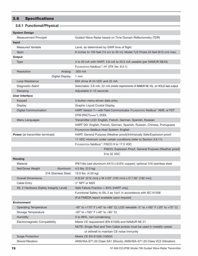
72 57-606 ECLIPSE Model 706 Guided Wave Radar Transmitter
3.6 Specifications
3.6.1 Functional/Physical
System Design
Measurement Principle Guided Wave Radar based on Time Domain Reflectometry (TDR)
Input
Measured Variable Level, as determined by GWR time of flight
Span 6 inches to 100 feet (15 cm to 30 m); Model 7yS Probe 20 feet (610 cm) max.
Output
Type 4 to 20 mA with HART: 3.8 mA to 20.5 mA useable (per NAMUR NE43)
FOUNDATION fieldbus™: H1 (ITK Ver. 6.0.1)
Resolution Analog: .003 mA
Digital Display: 1 mm
Loop Resistance 634 ohms @ 24 VDC and 22 mA
Diagnostic Alarm Selectable: 3.6 mA, 22 mA (meets requirements of NAMUR NE 43), or HOLD last output
Damping Adjustable 0–10 seconds
User Interface
Keypad 4-button menu-driven data entry
Display Graphic Liquid Crystal Display
Digital Communication HART Version 7—with Field Communicator, FOUNDATION fieldbus™, AMS, or FDT
DTM (PACTware™), EDDL
Menu Languages Transmitter LCD: English, French, German, Spanish, Russian
HART DD: English, French, German, Spanish, Russian, Chinese, Portuguese
FOUNDATION fieldbus Host System: English
Power (at transmitter terminals) HART: General Purpose (Weather proof)/Intrinsically Safe/Explosion-proof:
11 VDC minimum under certain conditions (refer to Section 3.6.11)
FOUNDATION fieldbus™: FISCO 9 to 17.5 VDC
FNICO, Explosion Proof, General Purpose (Weather proof)
9 to 32 VDC
Housing
Material IP67/die cast aluminum A413 (<0.6% copper); optional 316 stainless steel
Net/Gross Weight Aluminum: 4.5 lbs. (2.0 kg)
316 Stainless Steel: 10.0 lbs. (4.50 kg)
Overall Dimensions H 8.34" (212 mm) x W 4.03" (102 mm) x D 7.56" (192 mm)
Cable Entry 1⁄2" NPT or M20
SIL 2 Hardware (Safety Integrity Level) Safe Failure Fraction = 93% (HART only)
Functional Safety to SIL 2 as 1oo1 in accordance with IEC 61508
(Full FMEDA report available upon request)
Environment
Operating Temperature -40° to +175° F (-40° to +80° C); LCD viewable -5° to +160° F (-20° to +70° C)
Storage Temperature -50° to +185° F (-46° to +85° C)
Humidity 0 to 99%, non-condensing
Electromagnetic Compatibility Meets CE requirement (EN 61326) and NAMUR NE 21
NOTE: Single Rod and Twin Cable probes must be used in metallic vessel
or stillwell to maintain CE noise immunity
Surge Protection Meets CE EN 61326 (1000V)
Shock/Vibration ANSI/ISA-S71.03 Class SA1 (Shock); ANSI/ISA-S71.03 Class VC2 (Vibration)

7357-606 ECLIPSE Model 706 Guided Wave Radar Transmitter
3.6.1 Functional/Physical
Performance
Reference Conditions Reflection from liquid, with dielectric constant in center of selected range,
with a 72" (180 mm) coaxial probe at +70° F (+20° C), in Auto Threshold Mode
Linearity Coaxial/Caged Probes: <0.1% of probe length or 0.1 inch (2.5 mm), whichever is greater
Single Rod in Tanks/Twin Cable: <0.3% of probe length or 0.3 inch (7.5 mm), whichever is greater
Accuracy Coaxial/Caged Probes: ±0.1% of probe length or ±0.1 inch (2.5 mm), whichever is greater
Single Rod in Tanks/Twin Cable: ±0.5% of probe length or ±0.5 inch (13 mm), whichever is greater
Interface Operation: Coaxial/Caged probes: ±1 inch (25 mm) for an interface thickness greater than
2 inches (50 mm)
Twin Flexible probes: ±2 inch (50 mm) for an interface thickness greater than
8 inches (200 mm)
Resolution ±0.1 inch (2.5 mm)
Repeatability <0.1 inch (2.5 mm)
Hysteresis <0.1 inch (2.5 mm)
Response Time Approximately 1 second
Initialization Time Less than 10 seconds
Ambient Temperature Effect App. ±0.02% of probe length/degree C (for probes greater than 8 feet (2.5 m))
Process Dielectric Effect <0.3 inch (7.5 mm) within selected range
FOUNDATION fieldbus™
ITK Version 6.0.1
H1 Device Class Link Master (LAS)—selectable ON/OFF
H1 Profile Class 31PS, 32L
Function Blocks (8) Al, (3) Transducer, (1) Resource, (1) Arithmetic, (1) Input Selector,
(1) Signal Characterizer, (2) PID, (1) Integrator
Quiescent Current 15 mA
Execution Time 15 msec (40 msec PID Block)
Specifications will degrade in Fixed Threshold mode. Linearity in top 18 inches (46 cm) of Twin Cable and Single Rod probes in tanks will be application dependent. Accuracy may degrade when using manual or automatic compensation.

74 57-606 ECLIPSE Model 706 Guided Wave Radar Transmitter
3.6.2 O-ring (Seal) Selection Chart
Code O-Ring Material
Max. ProcessTemperature
Min. ProcessTemperature
Max. ProcessPressure
Not Recommended For Applications Recommended for Applications
0 Viton® GFLT400 °F @ 230 psi(200°C @ 16 bar)
-40° F(-40° C)
1000 psi 70° F(70 bar @20°C)
Ketones (MEK, acetone),skydrol fluids, amines,anhydrous ammonia, lowmolecular weight esters andethers, hot hydrofluoric orchlorosulfuric acids, sour
HCs
General purpose, ethylene
1 EPDM250 °F @ 200 psi(125 °C @14 bar)
-60° F(-50° C)
1000 psi 70° F(70 bar @20°C)
Petroleum oils, di-ester baselubricant, steam
Acetone, MEK, skydrol fluids
2 Kalrez® 4079400 °F @ 232 psi(200 °C @ 16 bar)
-40° F(-40° C)
1000 psi 70° F(70 bar @20°C)
Hot water/steam, hotaliphatic amines, ethyleneoxide, propylene oxide
Inorganic and organic acids (includinghydro fluids and nitric), aldehydes,
ethylene, organic oils, blycols, siliconeoils, vinegar, sour HCs
3HSN
(Highly SaturatedNitrile)
275 °F @ 320 psi(135 °C @ 22 bar)
-4° F(-20° C)
1000 psi 70° F(70 bar @20°C)
Halogenated HCs, nitro HCs,phosphate ester hydraulicfluids, ketones (MEK,acetone), strong acids,ozone, automotive brake
fluid, steam
NACE applications
4 Buna-N275 °F @ 320 psi(135 °C @ 22 bar)
-4° F(-20° C)
1000 psi 70° F(70 bar @20°C)
Halogenated HCs, nitro HCs,phosphate ester hydraulicfluids, ketones (MEK,acetone), strong acids,ozone, automotive brake
fluid
General purpose sealing,petroleum oils and fluids, coldwater, silicone greases and oils, di-ester base lubricants, ethylene
glycol base fluids
5 Neoprene® 300 °F @ 290 psi(150 °C @ 20 bar)
-65° F(-55° C)
1000 psi 70° F(70 bar @20°C)
Phosphate ester fluids,ketones (MEK, acetone)
Refrigerants, high anline pointpetroleum oils, silicate ester
lubricants
6 Chemraz® 505400 °F @ 200 psi(200 °C @ 14 bar)
-20° F(-30° C)
1000 psi 70° F(70 bar @20°C)
Acetaldehyde, ammonia +lithium metal solution,butyraldehyde, di-water,
freon, ethylene oxide, liquors,isobutyraldehyde
Inorganic and organic acids,alkalines, ketones, esters,
aldehydes, fuels
7 Polyurethane200 °F @ 420 psi(95 °C @29 bar)
-65° F(-55° C)
1000 psi 70° F(70 bar @20°C)
Acids, Ketones, chlorinated HCs,
Hydraulic systems, petroleum oils,HC fuel, oxygen, ozone
8 Aegis PF128 400 °F @ 232 psi(200 °C @ 16 bar)
-4° F(-20° C)
1000 psi 70° F(70 bar @20°C)
Black liquor, freon 43, freon75, galden, KEL-F liquid,molten potassium, molten
sodium
Inorganic and organic acids(including hydro fluids and nitric),aldehydes, ethylene, organic oils,gycols, silicone oils, vinegar, sour
HCs, steam, amines, ethylene oxide,propylene oxice, NACE applications
9 Kalrez® 2035400 °F @ 232 psi(200 °C @ 16 bar)
-40° F(-40° C)
1000 psi 70° F(70 bar @20°C)
Hot water/steam, hotaliphatic amines, ethyleneoxide, propylene oxide
Inorganic and organic acids(including hydro fluids and nitric),aldehydes, ethylene, organic oils,blycols, silicone oils, vinegar, sour
HCs
A Kalrez® 6375400 °F @ 232 psi(200 °C @ 16 bar)
-40° F(-40° C)
1000 psi 70° F(70 bar @20°C)
Hot water/steam, hotaliphatic amines, ethyleneoxide, propylene oxide
Inorganic and organic acids (includinghydro fluids and nitric), aldehydes,
ethylene, organic oils, blycols, siliconeoils, vinegar, sour HCs
Maximum +300° F (+150° C) for use on steam.

7557-606 ECLIPSE Model 706 Guided Wave Radar Transmitter
Launch Plate
COAXIAL/CAGED GWR PROBE TWIN CABLE GWR PROBE SINGLE ROD/CABLE PROBE
signal propagation signal propagation signal propagation
end view
end view
3.6.3 Probe Selection Guide
GWRProbe
Description Application Installation DielectricRange
TemperatureRange
Max.Pressure Vacuum Overfill
SafeViscositycP (mPa.s)
Coaxial GWR Probes—Liquids
7yT StandardTemperature Level/Interface Tank/Chamber εr 1.4–100 -40° to +400° F
(-40° to +200° C)1000 psi(70 bar) Yes Yes 500/2000
7yP HighPressure Level/Interface Tank/Chamber εr 1.4–100 -320° to +400° F
(-196° to +200° C)6250 psi(431 bar) Full Yes 500/2000
7yD High Temp./High Press. Level/Interface Tank/Chamber εr 1.4–100 -320° to +850° F
(-196° to +450° C)6250 psi(431 bar) Full Yes 500/2000
7yS SteamProbe
SaturatedSteam Tank/Chamber εr 10–100 -40° to +575° F
(-40° to +300° C)1275 psi(88 bar) Full No 500
Caged GWR Probes—Liquids
7yG StandardTemperature Level/Interface Chamber εr 1.4–100 -40° to +400° F
(-40° to +200° C)1000 psi(70 bar) Yes Yes 10000
7yL HighPressure Level/Interface Chamber εr 1.4–100 -320° to +400° F
(-196° to +200° C)6250 psi(431 bar) Full Yes 10000
7yJ High Temp./High Press. Level/Interface Chamber εr 1.4–100 -320° to +850° F
(-196° to +450° C)6250 psi(431 bar) Full Yes 10000
Single Rod Rigid GWR Probes—Liquids
7yF StandardTemperature Level Tank εr 1.7–100 -40° to +400° F
(-40° to +200° C)1000 psi(70 bar) Yes No 10000
7yM HighPressure Level Tank εr 1.7–100 -320° to +400° F
(-196° to +200° C)6250 psi(431 bar) Full No 10000
7yN High Temp./High Press. Level Tank εr 1.7–100 -320° to +850° F
(-196° to +450° C)6250 psi(431 bar) Full No 10000
Single Cable Flexible GWR Probes—Liquids
7y1 StandardTemperature Level Tank εr 1.7–100 -40° to +400° F
(-40° to +200° C)1000 psi(70 bar) Yes No 10000
7y3High Temp./High Press. Level Tank εr 1.7–100 -320° to +850° F
(-196° to +450° C)6250 psi(431 bar) Full No 10000
7y4Standard
Temperature Level/Interface Chamber εr 1.4–100 -40° to +400° F(-40° to +200° C)
1000 psi(70 bar) Yes No 10000
7y6High Temp./High Press Level/Interface Chamber εr 1.4–100 -320° to +850° F
(-196° to +450° C)6250 psi(431 bar) Full No 10000
Twin Cable Flexible GWR Probes—Liquids
7y7 StandardTemperature Level/Interface Tank εr 1.7–100 -40° to +400° F
(-40° to +200° C)1000 psi(70 bar) Yes No 1500
Twin Cable Flexible GWR Probes—Solids
7y5 Bulk SolidsProbe Level Tank εr 1.7–100 -40° to +150° F
(-40° to +65° C) Atmos. No No 1500
Single Cable Flexible GWR Probes—Solids
7y2 Bulk SolidsProbe Level Tank εr 4–100 -40° to +150° F
(-40° to +65° C) Atmos. No No 10000
2nd digit A=English, C=Metric Minimum εr 1.2 with end of probe analysis enabled. Single rod probes mounted directly into the vessel must be within 3–6 inches of metal tank wall to obtain minimum dielectric of 1.4, otherwise εr min = 1.7. Depends on the probe spacer material. Refer to Model Selection for spacer options. ECLIPSE probes containing o-rings can be used for vacuum (negative pressure) service, but only those probes with glass seals are hermetically sealed to <10-8 cc/sec @ 1 atmosphere helium.
Consult factory for overfill applications Overfill capability can be achieved with software. Scheduled for future release.

76 57-606 ECLIPSE Model 706 Guided Wave Radar Transmitter
Dual-element Probes
Single Rod Probes
NOTE: Transition Zone is dielectric dependent; εr = dielectric permittivity. The transmitter still operates butlevel reading may become nonlinear in Transition Zone.
ModelCoaxial / Cage
(7yG, 7yT)HP Coaxial/Cage
(7yL, 7yP)HTHP Coaxial/Cage
(7yD, 7yJ)Steam(7yS)
Flexible Twin Rod(7y5, 7y7)
Materials
316/316L SS (HastelloyC and Monel opt.)TFE spacers,Viton® O-rings
316/316L SS,glass ceramic alloy,
TFE spacers
316/316L SS,glass ceramic alloy,TFE or Peek™ spacers
316/316L SS,Peek™,
Aegis PF 128 O-ring
316/316L SSFEP CoatingViton® O-rings
Diameter
Small Coaxial: .3125" (8 mm) diameter rod, .875" (10 mm) diameter tubeTwo .25" (6 mm) dia.cables; .875" (22 mm)
CL to CL
Enlarged Coaxial: .6" (15 mm) dia. rod, 1.75" (44 mm) dia. tube N/A
Caged: 0.5" – 1.50" (13 – 38 mm) dia. rod N/A
ProcessConnection
3⁄4" NPT, 1" BSPANSI or DIN flanges
3⁄4" NPT, 1" BSPANSI or DIN flanges
3⁄4" NPT, 1" BSPANSI or DIN flanges
2" NPTANSI or DIN flanges
Transition Zone(Top)
None8" (200 mm) @
εr = 8012" (305 mm)
Transition Zone(Bottom)
6" (150 mm) @ εr = 1.41" (25 mm) @ εr = 80.0
6" (150 mm) @ εr = 1.41" (25 mm) @ εr = 80.0
1" (25 mm)@ εr = 80 12" (305 mm)
Pull Force/Tension N/A7x5: 3000 lbs.7x7: 100 lbs.
Model 7yF, 7yM, 7yN 7y1 Flexible 7y2 Flexible
Materials316/316L SS (Hastelloy® C and Monel optional)
Viton®/PEEK™ O-rings316/316L SS, Viton® O-rings
Diameter 0.5" (13 mm) 0.25" (6 mm)
Blocking Distance - Top 0–36" (0–91 cm)–Installation dependent (adjustable)
ProcessConnection
1" NPT (7yF)ANSI or DIN flange
2" NPTANSI or DIN flange
Transition Zone(Top)
Application Dependent
Transition Zone(Bottom)
1" @ εr >10 12" (305 mm) minimum
Pull Force/Tension N/A 20 lbs. 3000 lbs.
Side LoadNot more than 3" deflection atend of 120" (305 cm) probe
Cable not to exceed 5° from vertical
3.6.4 Probe Specifications

7777 57-606 ECLIPSE Model 706 Guided Wave Radar Transmitter
Temperature/Pressure Charts
3.6.5 Physical Specifications – Transmitterinches (mm)
NOTES:
• 7yS steam probes are rated to 1275 psi (88 bar) up to +575° F (+300° C)
• 7y3, 7y6 HTHP flexible probes: Pressure is limited by the chamber
• 7y2, 7y5 bulk solids probes: 50 psi (3.5 bar) to +150° F (+65° C)
• High pressure probes with threaded fittings are rated as follows:7yD, 7yN, 7yP and 7y3 probes with threaded fittings have 3600 psi (248 bar) rating.7yM probes with threaded fittings have 2016 psi (139 bar) rating.
3000
3500
4000
4500
5000
5500
6000
6500M
axim
um P
ress
ure
(PS
I)
0 100 200 300 400 500
Temperature (°F)
316/316L SST
7yL, 7yM and 7yPTemperature/Pressure Ratings
Hastelloy C276Monel 400
3000
3500
4000
4500
5000
5500
6000
6500
Max
imum
Pre
ssur
e (P
SI)
0 200 400 600 800 1000
Temperature (°F)
316/316L SST
7yD, 7yJ, 7yN, 7y3 and 7y6Temperature/Pressure Ratings
Hastelloy C276Monel 400
Eclipse® Housing(45° View)
3.38(86)
4.18(106)
3.77(96)
45°
9.30(236)
2 cableentries
4.03(102)
8.34(212)
5.09(129)
Eclipse® Housing(45° View)Integral Electronics
33 or 144(838 or 3650)
3.00(76)
2.37(60)
2.00(51)
3.50(89)
2 Holes.38 (10) Dia.
4.18(106)
3.38(86)
4.15(105)
45°
3.77(96)
3.75(95)
2 cableentries
Eclipse® Remote Configurations

78 57-606 ECLIPSE Model 706 Guided Wave Radar Transmitter
3.6.6 Physical Specifications – Coaxial Probesinches (mm)
MountingFlange
3.38(86)
4.18(106)
3.77(96)
45°
9.30(236)
4.46(113)
ProbeInsertionLength
2 cableentries
Model 7yTwith flanged connection
3.38(86)
4.18(106)
3.77(96)
45°
9.30(236)
2 cableentries
MountingFlange
7.76(197)
ProbeInsertionLength
Model 7yPwith flanged connection
3.38(86)
4.18(106)
3.77(96)
45°
9.30(236)
2 cableentries
11.55(293)
ProbeInsertionLength
MountingFlange
Model 7ySwith flanged connection
3.38(86)
4.18(106)
3.77(96)
45°
9.30(236)
2 cableentries
10.45(265)
ProbeInsertionLength
Model 7yDwith flanged connection
C
E
D
Coaxial Probe Slots
A
B
Coaxial GWR Probe,End View
Dim. Small Diameter Enlarged (standard)
A 0.88 (22.5) 1.75 (45) - SST1.92 (49) - HC and Monel
B 0.31 (8) 0.63 (16)
C 4.08 (100) 6.05 (153)
D 0.15 (4) 0.30 (8)
E 3.78 (96) 5.45 (138)

7957-606 ECLIPSE Model 706 Guided Wave Radar Transmitter
3.38(86)
4.18(106)
3.77(96)
45°
9.30(236)
2 cableentries
MountingFlange
4.70(119)
ProbeInsertionLength
Model 7yGwith flanged connection
3.38(86)
4.18(106)
3.77(96)
45°
9.30(236)
2 cableentries
MountingFlange
6.39(162)
ProbeInsertionLength
Model 7yLwith flanged connection
3.38(86)
4.18(106)
3.77(96)
45°
9.30(236)
2 cableentries
MountingFlange
10.45(265)
ProbeInsertionLength
Model 7yJwith flanged connection
3.6.7 Physical Specifications – Caged Probesinches (mm)
Cage Size Probe Rod Diameter (D) Spacer Length (L)
2" 0.5 to 0.75" (13 to 19 mm) 1.82" (46 mm)
3" 0.75 to 1.13" (19 to 29 mm) 2.64" (67 mm)
4" 1.05 to 1.50" (27 to 38 mm) 3.60" (91 mm)

80 57-606 ECLIPSE Model 706 Guided Wave Radar Transmitter
3.6.8 Physical Specifications – Single Rod Flexible Probesinches (mm)
3.38(86)
4.18(106)
3.77(96)
45°
9.30(236)
2 cableentries
4.53(115)
ProbeInsertionLength
MountingFlange
3.88(99) 0.19 (0.5)
0.75 (19)
2.0 (51)
Model 7y1with flanged connection
3.38(86)
4.18(106)
3.77(96)
45°
9.30(236)
2 cableentries
5.46(139)
ProbeInsertionLength
MountingFlange
2.0 (51)
6.0(152)
Model 7y2with flanged connection
3.38(86)
4.18(106)
3.77(96)
45°
9.30(236)
2 cableentries
10.45(265)
MountingFlange
ProbeInsertionLength
6.0(152)
2.0 (51)
Model 7y3with flangedconnection
3.38(86)
4.18(106)
3.77(96)
45°
9.30(236)
2 cableentries
MountingFlange
4.70(119)
ProbeInsertionLength
2.0 (51)
6.0(152)
Model 7y4with flanged connection
3.38(86)
4.18(106)
3.77(96)
45°
9.30(236)
2 cableentries
MountingFlange
10.45(265)
ProbeInsertionLength
2.0 (51)
6.0(152)
Model 7y6with flangedconnection
6(152)
7x2: SST Weight5 lbs (2.25 kg)
order code: 004-8778-001(2) 010-1731-001
Ø 2(51)

8157-606 ECLIPSE Model 706 Guided Wave Radar Transmitter
0.875 (22.2)
Ø 0.50 (13) Rods
0.248 (6.3)
Twin Rod GWR Probeend view
3.38(86)
4.18(106)
3.77(96)
45°
9.30(236)
2 cableentries
4.54(115)
ProbeInsertionLength
MountingFlange
Model 7y7with flanged connection
3.38(86)
4.18(106)
3.77(96)
45°
9.30(236)
2 cableentries
5.31(135)
ProbeInsertionLength
MountingFlange
Model 7y5with flanged connection
3.6.10 Physical Specifications – Twin Rod Flexible Probesinches (mm)
7x5: SST Weight5 lbs (2.25 kg)
order code: 004-8778-002+ 2 x 010-1731-001
Ø 2.00(51)
6.00 (152)
3.6.9 Physical Specifications – Single Rod Rigid Probesinches (mm)
3.38(86)
4.18(106)
3.77(96)
45°
9.30(236)
2 cableentries
4.53(115)
ProbeInsertionLength
MountingFlange
.38 (9.6)
Model 7yFwith flanged connection
3.38(86)
4.18(106)
3.77(96)
45°
9.30(236)
2 cableentries
8.38(213)
ProbeInsertionLength
MountingFlange
.38 (9.6)
Model 7yMwith flanged connection
3.38(86)
4.18(106)
3.77(96)
45°
9.30(236)
2 cableentries
10.45(265)
ProbeInsertionLength
MountingFlange
.50 (13)
Model 7yNwith flanged connection

82 57-606 ECLIPSE Model 706 Guided Wave Radar Transmitter
Operational Mode Current Consumption Vmin Vmax
HART
General Purpose 4mA20mA
16.25V11V
36V36V
Intrinsically Safe 4mA20mA
16.25V11V
28.6V28.6V
Explosion Proof 4mA20mA
16.25V11V
36V36V
Fixed Current-Solar Power Operation (PV transmitter via HART)
General Purpose 10mA 11V 36V
Intrinsically Safe 10mA 11V 28.6V
HART Multi-Drop Mode (Fixed Current)
Standard 4mA 16.25V 36V
Intrinsically Safe 4mA 16.25V 28.6V
FOUNDATION fieldbus™ (Future)
Supply Voltage 9V to 32V
3.6.11 Power Supply Requirements
3.6.11.1 Safe Operating Area
Start-up current 12 mA minimum.
0
Vsupply
Typical HART4-20 mA
Operating AreaDigital Solar Mode
Safe Operating Area
16.25 V
591Ω
24 V 36 V
LoopR
3.6.11.2 Minimum Supply Voltage

8357-606 ECLIPSE Model 706 Guided Wave Radar Transmitter
1
3 . 7 . 1 MO D E L N UM B E R
T R A N SM I T T E R
1 2 3 | BASIC MODEL NUMBER
4 | POWER
5 | SIGNAL OUTPUT
6 | SAFETY OPTIONS
7 0 6 5
7 0 6 ECLIPSE 4th Generation Guided Wave Radar (GWR) Level Transmitter
5 24 VDC, Two-Wire
1 4–20 mA with HART
2 FOUNDATION fieldbus™ Communications — Future
0 Standard (FOUNDATION fieldbus only) — Future
1 SIL 2 Hardware - HART only
7 | ACCESSORIES/MOUNTING
0 No Digital Display or Keypad - Integral
1 No Digital Display or Keypad - 3-foot (1 meter) remote
2 No Digital Display or Keypad - 12-foot (3.6 meter) remote
A Digital Display and Keypad - Integral
B Digital Display and Keypad - 3-foot (1 meter) remote
C Digital Display and Keypad - 12-foot (3.6 meter) remote
8 | CLASSIFICATION
0 General Purpose, Weatherproof (IP 67)
1 Intrinsically Safe (FM & CSA CL 1 Div 1, Grps A, B, C, D)
3 Explosion-proof (FM & CSA CL 1 Div 1, Grps B, C, D)
A Intrinsically Safe (ATEX/IEC Ex ia IIC T4)
B Flame-proof (ATEX/IEC Ex d ia IIB T4)
C Non-incendive (ATEX Ex n IIC T6)
D Dust Ex (ATEX II)
9 | HOUSING
1 Die-cast Aluminum, Dual-compartment, 45-degree
2 Investment Cast, 316 SS, Dual-compartment, 45-degree
10 | CONDUIT CONNECTION
0 1⁄2" NPT
1 M20
2 1⁄2" NPT with sunshade
3 M20 with sunshade
1 2 3 4 5 6 7 8 9 10

84 57-606 ECLIPSE Model 706 Guided Wave Radar Transmitter
3 . 7 . 2 MO D E L N UM B E R
E N L A R G E D COA X I A L P R O B E
1 | TECHNOLOGY
2 | MEASUREMENT SYSTEM
3 | CONFIGURATION/STYLE (RIGID)
7
7 ECLIPSE GWR Probes - Model 706
A English
C Metric
D Enlarged Coaxial, High Temp/High Pressure: Overfill w/Glass Seal (+850° F/+450° C) — Available only with 10th digit N or D
P Enlarged Coaxial, High Pressure: Overfill w/Glass Seal (+400° F/+200° C) — Available only with 10th digit N or D
T Enlarged Coaxial, Overfill Standard O-Ring Seal (+400° F/+200° C) — Not available with 10th digit N or D
Torque Tube Mating Flanges
T T 600# Fisher (249B/259B) in carbon steel
T U 600# Fisher (249C) in stainless steel
U T 600# Masoneilan flange in carbon steel
U U 600# Masoneilan flange in stainless steel
4 5 | PROCESS CONNECTION – SIZE/TYPE (consult factory for other process connections)Threaded
ANSI Flanges
4 3 2" 150# ANSI RF
4 4 2" 300# ANSI RF
4 5 2" 600# ANSI RF
4 K 2" 600# ANSI RTJ
5 3 3" 150# ANSI RF
5 4 3" 300# ANSI RF
5 5 3" 600# ANSI RF
56 3" 900# ANSI RF
57 3" 1500# ANSI RF
58 3" 2500# ANSI RF
5K 3" 600# ANSI RTJ
5L 3" 900# ANSI RTJ
4 1 2" NPT Thread
5M 3" 1500# ANSI RTJ
5N 3" 2500# ANSI RTJ
6 3 4" 150# ANSI RF
6 4 4" 300# ANSI RF
6 5 4" 600# ANSI RF
6 6 4" 900# ANSI RF
6 7 4" 1500# ANSI RF
6 8 4" 2500# ANSI RF
6K 4" 600# ANSI RTJ
6L 4" 900# ANSI RTJ
6M 4" 1500# ANSI RTJ
6N 4" 2500# ANSI RTJ
EN Flanges
D A DN 50, PN 16 EN 1092-1 TYPE A
D B DN 50, PN 25/40 EN 1092-1 TYPE A
D D DN 50, PN 63 EN 1092-1 TYPE B2
D E DN 50, PN 100 EN 1092-1 TYPE B2
E A DN 80, PN 16 EN 1092-1 TYPE A
E B DN 80, PN 25/40 EN 1092-1 TYPE A
E D DN 80, PN 63 EN 1092-1 TYPE B2
E E DN 80, PN 100 EN 1092-1 TYPE B2
E F DN 80, PN 160 EN 1092-1 TYPE B2
E G DN 80, PN 250 EN 1092-1 TYPE B2
E H DN 80, PN 320 EN 1092-1 TYPE B2
E J DN 80, PN 400 EN 1092-1 TYPE B2
F A DN 100, PN 16 EN 1092-1 TYPE A
F B DN 100, PN 25/40 EN 1092-1 TYPE A
F D DN 100, PN 63 EN 1092-1 TYPE B2
F E DN 100, PN 100 EN 1092-1 TYPE B2
F F DN 100, PN 160 EN 1092-1 TYPE B2
F G DN 100, PN 250 EN 1092-1 TYPE B2
F H DN 100, PN 320 EN 1092-1 TYPE B2
F J DN 100, PN 400 EN 1092-1 TYPE B2
4 2 2" BSP (G1) Thread
Confirm mounting conditions/nozzle diameter to ensure sufficient clearance. Always check dimensions if ANSI/EN flanges are not used.
1 2 3 4 5 6 7 8 9 10 11 12 13 14 15
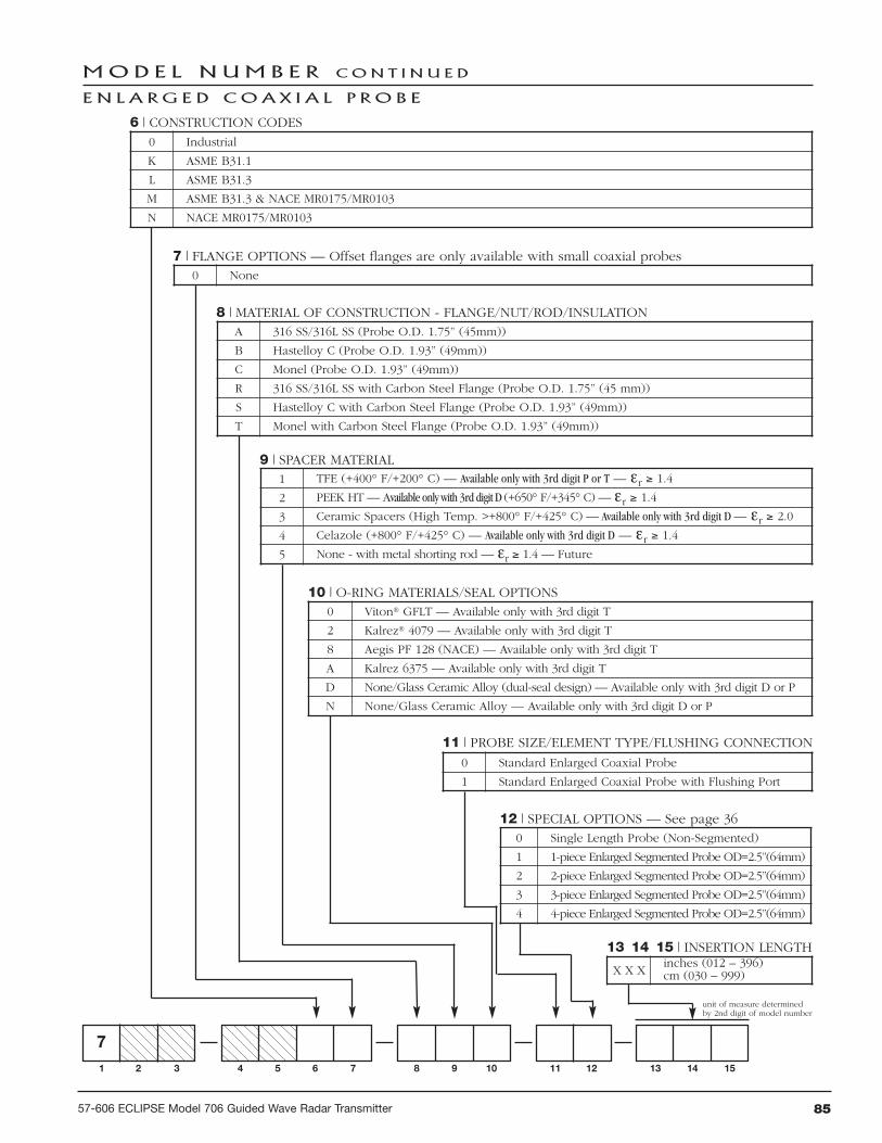
8557-606 ECLIPSE Model 706 Guided Wave Radar Transmitter
MOD E L N UM B E R CON T I N U E D
E N L A R G E D COA X I A L P R O B E
13 14 15 | INSERTION LENGTH
X X Xinches (012 – 396)cm (030 – 999)
unit of measure determinedby 2nd digit of model number
7 | FLANGE OPTIONS — Offset flanges are only available with small coaxial probes0 None
6 | CONSTRUCTION CODES0 Industrial
K ASME B31.1
L ASME B31.3
M ASME B31.3 & NACE MR0175/MR0103
N NACE MR0175/MR0103
8 | MATERIAL OF CONSTRUCTION - FLANGE/NUT/ROD/INSULATIONA 316 SS/316L SS (Probe O.D. 1.75” (45mm))
B Hastelloy C (Probe O.D. 1.93” (49mm))
C Monel (Probe O.D. 1.93” (49mm))
R 316 SS/316L SS with Carbon Steel Flange (Probe O.D. 1.75” (45 mm))
S Hastelloy C with Carbon Steel Flange (Probe O.D. 1.93” (49mm))
T Monel with Carbon Steel Flange (Probe O.D. 1.93” (49mm))
9 | SPACER MATERIAL1 TFE (+400° F/+200° C) — Available only with 3rd digit P or T — εr ≥ 1.42 PEEK HT — Available only with 3rd digit D (+650° F/+345° C) — εr ≥ 1.43 Ceramic Spacers (High Temp. >+800° F/+425° C) — Available only with 3rd digit D— εr ≥ 2.04 Celazole (+800° F/+425° C) — Available only with 3rd digit D — εr ≥ 1.45 None - with metal shorting rod — εr ≥ 1.4 — Future
10 | O-RING MATERIALS/SEAL OPTIONS0 Viton® GFLT — Available only with 3rd digit T
2 Kalrez® 4079 — Available only with 3rd digit T
8 Aegis PF 128 (NACE) — Available only with 3rd digit T
A Kalrez 6375 — Available only with 3rd digit T
D None/Glass Ceramic Alloy (dual-seal design) — Available only with 3rd digit D or P
N None/Glass Ceramic Alloy — Available only with 3rd digit D or P
11 | PROBE SIZE/ELEMENT TYPE/FLUSHING CONNECTION
0 Standard Enlarged Coaxial Probe
1 Standard Enlarged Coaxial Probe with Flushing Port
12 | SPECIAL OPTIONS — See page 360 Single Length Probe (Non-Segmented)
1 1-piece Enlarged Segmented Probe OD=2.5”(64mm)
2 2-piece Enlarged Segmented Probe OD=2.5”(64mm)
3 3-piece Enlarged Segmented Probe OD=2.5”(64mm)
4 4-piece Enlarged Segmented Probe OD=2.5”(64mm)
71 2 3 4 5 6 7 8 9 10 11 12 13 14 15
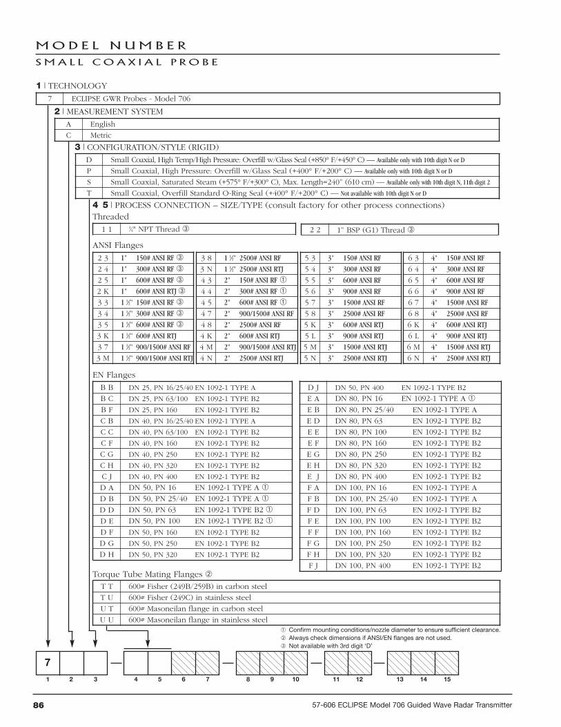
86 57-606 ECLIPSE Model 706 Guided Wave Radar Transmitter
MOD E L N UM B E R
SMA L L COA X I A L P R O B E
71 2 3 4 5 6 7 8 9 10 11 12 13 14 15
1 | TECHNOLOGY
2 | MEASUREMENT SYSTEM
3 | CONFIGURATION/STYLE (RIGID)
7 ECLIPSE GWR Probes - Model 706
A English
C Metric
D Small Coaxial, High Temp/High Pressure: Overfill w/Glass Seal (+850° F/+450° C) — Available only with 10th digit N or D
P Small Coaxial, High Pressure: Overfill w/Glass Seal (+400° F/+200° C) — Available only with 10th digit N or D
S Small Coaxial, Saturated Steam (+575° F/+300° C), Max. Length=240” (610 cm) — Available only with 10th digit N, 11th digit 2
T Small Coaxial, Overfill Standard O-Ring Seal (+400° F/+200° C) — Not available with 10th digit N or D
4 5 | PROCESS CONNECTION – SIZE/TYPE (consult factory for other process connections)Threaded
1 1 3⁄4" NPT Thread 2 2 1” BSP (G1) Thread
Confirm mounting conditions/nozzle diameter to ensure sufficient clearance. Always check dimensions if ANSI/EN flanges are not used. Not available with 3rd digit ‘D’
EN Flanges
B B DN 25, PN 16/25/40 EN 1092-1 TYPE A
B C DN 25, PN 63/100 EN 1092-1 TYPE B2
B F DN 25, PN 160 EN 1092-1 TYPE B2
C B DN 40, PN 16/25/40 EN 1092-1 TYPE A
C C DN 40, PN 63/100 EN 1092-1 TYPE B2
C F DN 40, PN 160 EN 1092-1 TYPE B2
C G DN 40, PN 250 EN 1092-1 TYPE B2
C H DN 40, PN 320 EN 1092-1 TYPE B2
C J DN 40, PN 400 EN 1092-1 TYPE B2
D A DN 50, PN 16 EN 1092-1 TYPE A
D B DN 50, PN 25/40 EN 1092-1 TYPE A
D D DN 50, PN 63 EN 1092-1 TYPE B2
D E DN 50, PN 100 EN 1092-1 TYPE B2
D F DN 50, PN 160 EN 1092-1 TYPE B2
D G DN 50, PN 250 EN 1092-1 TYPE B2
D H DN 50, PN 320 EN 1092-1 TYPE B2
D J DN 50, PN 400 EN 1092-1 TYPE B2
E A DN 80, PN 16 EN 1092-1 TYPE A
E B DN 80, PN 25/40 EN 1092-1 TYPE A
E D DN 80, PN 63 EN 1092-1 TYPE B2
E E DN 80, PN 100 EN 1092-1 TYPE B2
E F DN 80, PN 160 EN 1092-1 TYPE B2
E G DN 80, PN 250 EN 1092-1 TYPE B2
E H DN 80, PN 320 EN 1092-1 TYPE B2
E J DN 80, PN 400 EN 1092-1 TYPE B2
F A DN 100, PN 16 EN 1092-1 TYPE A
F B DN 100, PN 25/40 EN 1092-1 TYPE A
F D DN 100, PN 63 EN 1092-1 TYPE B2
F E DN 100, PN 100 EN 1092-1 TYPE B2
F F DN 100, PN 160 EN 1092-1 TYPE B2
F G DN 100, PN 250 EN 1092-1 TYPE B2
F H DN 100, PN 320 EN 1092-1 TYPE B2
F J DN 100, PN 400 EN 1092-1 TYPE B2
ANSI Flanges
2 3 1" 150# ANSI RF
2 4 1" 300# ANSI RF
2 5 1" 600# ANSI RF
2 K 1" 600# ANSI RTJ
3 3 1 1⁄2" 150# ANSI RF
3 4 1 1⁄2" 300# ANSI RF
3 5 1 1⁄2" 600# ANSI RF
3 K 1 1⁄2" 600# ANSI RTJ
3 7 1 1⁄2" 900/1500# ANSI RF
3 M 1 1⁄2" 900/1500# ANSI RTJ
3 8 1 1⁄2" 2500# ANSI RF
3 N 1 1⁄2" 2500# ANSI RTJ
4 3 2" 150# ANSI RF
4 4 2" 300# ANSI RF
4 5 2" 600# ANSI RF
4 7 2" 900/1500# ANSI RF
4 8 2" 2500# ANSI RF
4 K 2" 600# ANSI RTJ
4 M 2" 900/1500# ANSI RTJ
4 N 2" 2500# ANSI RTJ
5 3 3" 150# ANSI RF
5 4 3" 300# ANSI RF
5 5 3" 600# ANSI RF
5 6 3" 900# ANSI RF
5 7 3" 1500# ANSI RF
5 8 3" 2500# ANSI RF
5 K 3" 600# ANSI RTJ
5 L 3" 900# ANSI RTJ
5 M 3" 1500# ANSI RTJ
5 N 3" 2500# ANSI RTJ
6 3 4" 150# ANSI RF
6 4 4" 300# ANSI RF
6 5 4" 600# ANSI RF
6 6 4" 900# ANSI RF
6 7 4" 1500# ANSI RF
6 8 4" 2500# ANSI RF
6 K 4" 600# ANSI RTJ
6 L 4" 900# ANSI RTJ
6 M 4" 1500# ANSI RTJ
6 N 4" 2500# ANSI RTJ
Torque Tube Mating Flanges T T 600# Fisher (249B/259B) in carbon steel
T U 600# Fisher (249C) in stainless steel
U T 600# Masoneilan flange in carbon steel
U U 600# Masoneilan flange in stainless steel

8757-606 ECLIPSE Model 706 Guided Wave Radar Transmitter
M O D E L N U M B E R C O N T I N U E D
S M A L L C O A X I A L P R O B E
13 14 15 | INSERTION LENGTH
X X Xinches (012 – 240)cm (030 – 610)
unit of measure determinedby 2nd digit of model number
7 | FLANGE OPTIONS — Offset flanges are only available with small coaxial probes0 None
1 Offset (For use with AURORA) — 3” Available only with 3rd digit P, S or T
2 Offset with 1⁄2" NPT (For use with AURORA) — 3” Available only with 3rd digit P, S or T
3 Offset with 3⁄4" NPT (For use with AURORA) — 3” Available only with 3rd digit P, S or T
6 | CONSTRUCTION CODES0 Industrial
K ASME B31.1
L ASME B31.3
M ASME B31.3 & NACE MR0175/MR0103
N NACE MR0175/MR0103
8 | MATERIAL OF CONSTRUCTION - FLANGE/NUT/ROD/INSULATIONA 316 SS/316L SS
B Hastelloy C
C Monel — Not available with 3rd Digit S
R 316 SS/316L SS with Carbon Steel Flange
S Hastelloy C with Carbon Steel Flange
T Monel with Carbon Steel Flange — Not available with 3rd Digit S
9 | SPACER MATERIAL1 TFE (+400° F/+200° C) — Available only with 3rd digit P or T — r 1.4
2 PEEK HT — Available only with 3rd digit D (+650° F/+345° C) or S (+575° F/+300° C) — r 1.4
3 Ceramic Spacers (Temp. >+800° F/+425° C) — Available only with 3rd digit D — r 2.0
5 None - with metal shorting rod — r 1.4 — Future
10 | O-RING MATERIALS/SEAL OPTIONS0 Viton® GFLT — Available only with 3rd digit T
2 Kalrez® 4079 — Available only with 3rd digit T
8 Aegis PF 128 (NACE) — Available only with 3rd digit T
A Kalrez 6375 — Available only with 3rd digit T
D None/Glass Ceramic Alloy (dual-seal design) — Available only with 3rd digit D or P
N None/Glass Ceramic Alloy — Available only with 3rd digit D, P or S
11 | PROBE SIZE/ELEMENT TYPE/FLUSHING CONNECTION2 Small Coaxial (0.875 inches/22 mm)
12 | SPECIAL OPTIONS0 Single Length Probe (Non-Segmented)
7 21 2 3 4 5 6 7 8 9 10 11 12 13 14 15
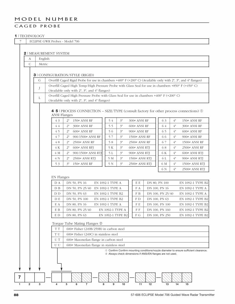
88 57-606 ECLIPSE Model 706 Guided Wave Radar Transmitter
MOD E L N UM B E R
C AG E D P R O B E
1 | TECHNOLOGY
2 | MEASUREMENT SYSTEM
3 | CONFIGURATION/STYLE (RIGID)
7 ECLIPSE GWR Probes - Model 706
A English
C Metric
G Overfill Caged Rigid Probe for use in chambers +400° F (+200° C) (Available only with 2", 3", and 4" flanges)
JOverfill Caged High Temp/High Pressure Probe with Glass Seal for use in chambers +850° F (+450° C)
(Available only with 2", 3", and 4" flanges)
LOverfill Caged High Pressure Probe with Glass Seal for use in chambers +400° F (+200° C)
(Available only with 2", 3", and 4" flanges)
Torque Tube Mating Flanges
T T 600# Fisher (249B/259B) in carbon steel
T U 600# Fisher (249C) in stainless steel
U T 600# Masoneilan flange in carbon steel
U U 600# Masoneilan flange in stainless steel
4 5 | PROCESS CONNECTION – SIZE/TYPE (consult factory for other process connections)
Confirm Confirm mounting conditions/nozzle diameter to ensure sufficient clearance. Always check dimensions if ANSI/EN flanges are not used.
71 2 3 4 5 6 7 8 9 10 11 12 13 14 15
EN Flanges
D A DN 50, PN 16 EN 1092-1 TYPE A
D B DN 50, PN 25/40 EN 1092-1 TYPE A
D D DN 50, PN 63 EN 1092-1 TYPE B2
D E DN 50, PN 100 EN 1092-1 TYPE B2
E A DN 80, PN 16 EN 1092-1 TYPE A
E B DN 80, PN 25/40 EN 1092-1 TYPE A
E D DN 80, PN 63 EN 1092-1 TYPE B2
E E DN 80, PN 100 EN 1092-1 TYPE B2
F A DN 100, PN 16 EN 1092-1 TYPE A
F B DN 100, PN 25/40 EN 1092-1 TYPE A
F D DN 100, PN 63 EN 1092-1 TYPE B2
F E DN 100, PN 100 EN 1092-1 TYPE B2
F F DN 100, PN 160 EN 1092-1 TYPE B2
F G DN 100, PN 250 EN 1092-1 TYPE B2
ANSI Flanges
4 3 2" 150# ANSI RF
4 4 2" 300# ANSI RF
4 5 2" 600# ANSI RF
4 7 2" 900/1500# ANSI RF
4 8 2" 2500# ANSI RF
4 K 2" 600# ANSI RFJ
4 M 2" 900/1500# ANSI RTJ
4 N 2" 2500# ANSI RTJ
5 3 3" 150# ANSI RF
5 4 3" 300# ANSI RF
5 5 3" 600# ANSI RF
5 6 3" 900# ANSI RF
5 7 3" 1500# ANSI RF
5 8 3" 2500# ANSI RF
5 K 3" 600# ANSI RTJ
5 L 3" 900# ANSI RTJ
5 M 3" 1500# ANSI RTJ
5 N 3" 2500# ANSI RTJ
6 3 4" 150# ANSI RF
6 4 4" 300# ANSI RF
6 5 4" 600# ANSI RF
6 6 4" 900# ANSI RF
6 7 4" 1500# ANSI RF
6 8 4" 2500# ANSI RF
6 K 4" 600# ANSI RTJ
6 L 4" 900# ANSI RTJ
6 M 4" 1500# ANSI RTJ
6 N 4" 2500# ANSI RTJ

8957-606 ECLIPSE Model 706 Guided Wave Radar Transmitter
M O D E L N U M B E R C O N T I N U E D
C A G E D P R O B E
6 | CONSTRUCTION CODES
7 | FLANGE OPTIONS
8 | MATERIAL OF CONSTRUCTION - MFG/NUT/ROD/INSULATION
0 Industrial
K ASME B31.1
L ASME B31.3
M ASME B31.3 & NACE MR0175/MR0103
N NACE MR0175/MR0103
9 | SPACER MATERIAL
2 PEEK HT (+650° F/+345° C)
3 Ceramic (High Temp.>+800° F/+450° C) — Available only with 3rd digit J
4 Celazole® (+800° F/+425° C) — Available only with 3rd digit J
13 14 15 | INSERTION LENGTH
X X Xinches (012 – 288)cm (030 – 732)
unit of measure determinedby 2nd digit of model number
10 | O-RING MATERIALS/SEAL OPTIONS
0 Viton® GFLT — Not available with 3rd digit J or L
2 Kalrez 4079 — Not available with 3rd digit J or L
8 Aegis PF 128 (NACE) — Not available with 3rd digit J or L
A Kalrez 6375 — Not available with 3rd digit J or L
DNone/Glass Ceramic Alloy (Dual Seal Design) —Not available with 3rd digit G
NNone/Glass Ceramic Alloy —Not available with 3rd digit G
0 None
1 Offset with 1⁄2” (For use with AURORA) Available only with 3rd digit G and 4th digit 6
2 Offset (For use with AURORA) Available only with 3rd digit G and 4th digit 6
3 Offset (For use with AURORA) Available only with 3rd digit G and 4th digit 6
A 316 SS/316L SS
B Hastelloy C
C Monel
R 316 SS/316L SS with Carbon Steel Flange
S Hastelloy C with Carbon Steel Flange
T Monel with Carbon Steel Flange
11 | PROBE SIZE/ELEMENT TYPE/FLUSHING CONNECTION
1 Single Length Removable Probe
2 2-piece Segmented Probe
3 3-piece Segmented Probe
4 4-piece Segmented Probe
12 | SPECIAL OPTIONS — See page 36
0 None
7 01 2 3 4 5 6 7 8 9 10 11 12 13 14 15

90 57-606 ECLIPSE Model 706 Guided Wave Radar Transmitter
MOD E L N UM B E R
S I N G L E R O D R I G I D P R O B E
1 | TECHNOLOGY
2 | MEASUREMENT SYSTEM
3 | CONFIGURATION/STYLE (RIGID)
7 ECLIPSE GWR Probes - Model 706
A English
C Metric
F Single Rod, Standard (+400° F/200° C) for in-tank applications
M Single Rod, High Pressure Probe with glass seal (+400° F/+200° C), for in-tank applications
N Single Rod, High Temp/High Pressure with glass seal (+850° F/+450° C), for in-tank applications
4 5 | PROCESS CONNECTION – SIZE/TYPE (consult factory for other process connections) Threaded
2 1 1" NPT Thread (7yF only)
4 1 2" NPT Thread
2 2 1" BSP (G1) Thread (7yF only)
4 2 2" BSP (G1) Thread
71 2 3 4 5 6 7 8 9 10 11 12 13 14 15
Confirm mounting conditions/nozzle diameter to ensure sufficient clearance.
EN Flanges
B B DN 25, PN 16/25/40 EN 1092-1 TYPE A
B C DN 25, PN 63/100 EN 1092-1 TYPE B2
B F DN 25, PN 160 EN 1092-1 TYPE B2
C B DN 40, PN 16/25/40 EN 1092-1 TYPE A
C C DN 40, PN 63/100 EN 1092-1 TYPE B2
C F DN 40, PN 160 EN 1092-1 TYPE B2
C G DN 40, PN 250 EN 1092-1 TYPE B2
C H DN 40, PN 320 EN 1092-1 TYPE B2
C J DN 40, PN 400 EN 1092-1 TYPE B2
D A DN 50, PN 16 EN 1092-1 TYPE A
D B DN 50, PN 25/40 EN 1092-1 TYPE A
D D DN 50, PN 63 EN 1092-1 TYPE B2
D E DN 50, PN 100 EN 1092-1 TYPE B2
D F DN 50, PN 160 EN 1092-1 TYPE B2
D G DN 50, PN 250 EN 1092-1 TYPE B2
D H DN 50, PN 320 EN 1092-1 TYPE B2
D J DN 50, PN 400 EN 1092-1 TYPE B2
E A DN 80, PN 16 EN 1092-1 TYPE A
E B DN 80, PN 25/40 EN 1092-1 TYPE A
E D DN 80, PN 63 EN 1092-1 TYPE B2
E E DN 80, PN 100 EN 1092-1 TYPE B2
E F DN 80, PN 160 EN 1092-1 TYPE B2
E G DN 80, PN 250 EN 1092-1 TYPE B2
E H DN 80, PN 320 EN 1092-1 TYPE B2
E J DN 80, PN 400 EN 1092-1 TYPE B2
F A DN 100, PN 16 EN 1092-1 TYPE A
F B DN 100, PN 25/40 EN 1092-1 TYPE A
F D DN 100, PN 63 EN 1092-1 TYPE B2
F E DN 100, PN 100 EN 1092-1 TYPE B2
F F DN 100, PN 160 EN 1092-1 TYPE B2
F G DN 100, PN 250 EN 1092-1 TYPE B2
F H DN 100, PN 320 EN 1092-1 TYPE B2
F J DN 100, PN 400 EN 1092-1 TYPE B2
ANSI Flanges
2 3 1" 150# ANSI RF
2 4 1" 300# ANSI RF
2 5 1" 600# ANSI RF
3 3 1 1⁄2" 150# ANSI RF
3 4 1 1⁄2" 300# ANSI RF
3 5 1 1⁄2" 600# ANSI RF
4 3 2" 150# ANSI RF
4 4 2" 300# ANSI RF
4 5 2" 600# ANSI RF
4 7 2" 900/1500# ANSI RF
4 8 2" 2500# ANSI RF
4 K 2" 600# ANSI RTJ
4 M 2" 900/1500# ANSI RTJ
4 N 2" 2500# ANSI RTJ
5 3 3" 150# ANSI RF
5 4 3" 300# ANSI RF
5 5 3" 600# ANSI RF
5 6 3" 900# ANSI RF
5 7 3" 1500# ANSI RF
5 8 3" 2500# ANSI RF
5 K 3" 600# ANSI RTJ
5 L 3" 900# ANSI RTJ
5 M 3" 1500# ANSI RTJ
5 N 3" 2500# ANSI RTJ
6 3 4" 150# ANSI RF
6 4 4" 300# ANSI RF
6 5 4" 600# ANSI RF
6 6 4" 900# ANSI RF
6 7 4" 1500# ANSI RF
6 8 4" 2500# ANSI RF
6 K 4" 600# ANSI RTJ
6 L 4" 900# ANSI RTJ
6 M 4" 1500# ANSI RTJ
6 N 4" 2500# ANSI RTJ

9157-606 ECLIPSE Model 706 Guided Wave Radar Transmitter
M O D E L N U M B E R C O N T I N U E D
S I N G L E R O D R I G I D P R O B E
6 | CONSTRUCTION CODES
7 | FLANGE OPTIONS
0 Industrial
K ASME B31.1
L ASME B31.3
M ASME B31.3 & NACE MR0175/MR0103
N NACE MR0175/MR0103
0 None
12 | SPECIAL OPTIONS
0 Non-Removable Rod—Only available with 8th digit F or P
1 Removable Rod — Not available with 8th Digit F or P
11 | PROBE SIZE/ELEMENT TYPE/FLUSHING CONNECTION
0 Standard Single Rod
13 14 15 | INSERTION LENGTH
X X Xinches (012 – 288)cm (030 – 732)
unit of measure determinedby 2nd digit of model number
8 | MATERIAL OF CONSTRUCTION - MFG/NUT/ROD/INSULATION
A 316 SS/316L SS
B Hastelloy C
C Monel
F Faced Flange, PFA coated wetted surfaces — Available only with Digit 3rd digit F
P PFA coated rod — Available only with Digit 3rd digit F
R 316 SS/316L SS with Carbon Steel Flange
S Hastelloy C with Carbon Steel Flange
T Monel with Carbon Steel Flange
9 | SPACER MATERIAL
0 None
2 PEEK HT (+650° F/+345° C) — Available only with 3rd digit N
3 Ceramic (High Temp.>+800° F/+450° C) — Available only with 3rd digit J
4 Celazole® (+800° F/+425° C) — Available only with 3rd digit J
10 | O-RING MATERIALS/SEAL OPTIONS
0 Viton® GFLT — Not available with 3rd digit M or N
2 Kalrez 4079 — Not available with 3rd digit M or N
8 Aegis PF 128 (NACE) — Not available with 3rd digit M or N
A Kalrez 6375 — Not available with 3rd digit M or N
D None/Glass Ceramic Alloy — Not available with 3rd digit F
N None/Glass Ceramic Alloy — Not available with 3rd digit F
7 0 01 2 3 4 5 6 7 8 9 10 11 12 13 14 15

92 57-606 ECLIPSE Model 706 Guided Wave Radar Transmitter
MOD E L N UM B E R
S I N G L E F L E X I B L E P R O B E
1 | TECHNOLOGY
2 | MEASUREMENT SYSTEM
3 | SPECIALTY FLEXIBLE PROBES
7 ECLIPSE GWR Probes - Model 706
A English
C Metric
1 Single Cable Flexible standard for in-tank applications (+400° F/+200° C)
2 Single Cable Flexible Light Duty Bulk Solids
3 Single Cable Flexible HTHP for in-tank applications (+850° F/+450° C) — (Future)
4 Single Cable Flexible standard for chamber applications (+400° F/+200° C) — (Future)
6 Single Cable Flexible HTHP for chamber applications (+850° F/+450° C) — (Future)
ANSI Flanges
4 3 2" 150# ANSI RF
4 4 2" 300# ANSI RF
4 5 2" 600# ANSI RF
5 3 3" 150# ANSI RF
5 4 3" 300# ANSI RF
5 5 3" 600# ANSI RF
6 3 4" 150# ANSI RF
6 4 4" 300# ANSI RF
6 5 4" 600# ANSI RF
EN Flanges
D A DN 50, PN 16 EN 1092-1 TYPE A
D B DN 50, PN 25/40 EN 1092-1 TYPE A
D D DN 50, PN 63 EN 1092-1 TYPE B2
D E DN 50, PN 100 EN 1092-1 TYPE B2
E A DN 80, PN 16 EN 1092-1 TYPE A
E B DN 80, PN 25/40 EN 1092-1 TYPE A
E D DN 80, PN 63 EN 1092-1 TYPE B2
E E DN 80, PN 100 EN 1092-1 TYPE B2
F A DN 100, PN 16 EN 1092-1 TYPE A
F B DN 100, PN 25/40 EN 1092-1 TYPE A
F D DN 100, PN 63 EN 1092-1 TYPE B2
F E DN 100, PN 100 EN 1092-1 TYPE B2
4 5 | PROCESS CONNECTION – SIZE/TYPE (consult factory for other process connections)
Threaded
4 1 2" NPT Thread 4 2 2" BSP (G1) Thread
71 2 3 4 5 6 7 8 9 10 11 12 13 14 15

9357-606 ECLIPSE Model 706 Guided Wave Radar Transmitter
MOD E L N UM B E R CON T I N U E D
S I N G L E F L E X I B L E P R O B E
11 | PROBE SIZE/ELEMENT TYPE/FLUSHING CONNECTION
3 Flexible Cable Probe
12 | SPECIAL OPTIONS
9 | SPACER MATERIAL
0 None
8 | MATERIAL OF CONSTRUCTION - MFG/NUT/ROD/INSULATION
A 316 SS/316L SS
R 316 SS/316L SS with Carbon Steel Flange
7 | FLANGE OPTIONS
0 None
6 | CONSTRUCTION CODES
0 Industrial
10 | O-RING MATERIALS/SEAL OPTIONS
0 Viton® GFLT
2 Kalrez 4079
8 Aegis PF 128 (NACE)
A Kalrez 6375
13 14 15 | INSERTION LENGTH
X X Xfeet (003 – 100)meters (001 – 030)
unit of measure determinedby 2nd digit of model number
7 0 0 0 31 2 3 4 5 6 7 8 9 10 11 12 13 14 15
0Non-removable Probe Cable(for use with 3rd digit '2' only)
1Removable Single-piece Probe Cable(for use with 3rd digit '1' only)

94 57-606 ECLIPSE Model 706 Guided Wave Radar Transmitter
MOD E L N UM B E R
T W I N F L E X I B L E P R O B E
1 | TECHNOLOGY
2 | MEASUREMENT SYSTEM
3 | SPECIALTY FLEXIBLE PROBES
7 ECLIPSE GWR Probes - Model 706
A English
C Metric
5 Twin Flexible Light Duty Bulk Solids with FEP Webbing
7 Twin Flexible - 316 SS with FEP Webbing
ANSI Flanges
5 3 3" 150 lbs. ANSI RF
5 4 3" 300 lbs. ANSI RF
5 5 3" 600 lbs. ANSI RF
6 3 4" 150 lbs. ANSI RF
6 4 4" 300 lbs. ANSI RF
6 5 4" 600 lbs. ANSI RF
EN Flanges
E A DN 80, PN 16 EN 1092-1 TYPE A
E B DN 80, PN 25/40 EN 1092-1 TYPE A
E D DN 80, PN 63 EN 1092-1 TYPE B2
E E DN 80, PN 100 EN 1092-1 TYPE B2
F A DN 100, PN 16 EN 1092-1 TYPE A
F B DN 100, PN 25/40 EN 1092-1 TYPE A
F D DN 100, PN 63 EN 1092-1 TYPE B2
F E DN 100, PN 100 EN 1092-1 TYPE B2
4 5 | PROCESS CONNECTION – SIZE/TYPE (consult factory for other process connections)
71 2 3 4 5 6 7 8 9 10 11 12 13 14 15

9557-606 ECLIPSE Model 706 Guided Wave Radar Transmitter
MOD E L N UM B E R CON T I N U E D
T W I N F L E X I B L E P R O B E
6 | CONSTRUCTION CODES
7 | FLANGE OPTIONS
8 | MATERIAL OF CONSTRUCTION - MFG/NUT/ROD/INSULATION
0 Industrial
0 None
A 316 SS/316L SS
R 316 SS/316L SS with Carbon Steel Flange
9 | SPACER MATERIAL
0 None
10 | O-RING MATERIALS/SEAL OPTIONS
0 Viton® GFLT
2 Kalrez 4079
8 Aegis PF 128 (NACE)
A Kalrez 6375
11 | PROBE SIZE/ELEMENT TYPE/FLUSHING CONNECTION
3 Flexible Cable Probe
12 | SPECIAL OPTIONS
0 None
13 14 15 | INSERTION LENGTH
X X Xfeet (003 – 100)meters (001 – 030)
unit of measure determinedby 2nd digit of model number
7 0 0 0 3 01 2 3 4 5 6 7 8 9 10 11 12 13 14 15

96 57-606 ECLIPSE Model 706 Guided Wave Radar Transmitter
S E GM E N T E D P R O B E O P T I O N S
1 2 t h D I G I T O F MOD E L N UM B E R
Probe Model One Segment Two Segments Three Segments Four Segments
Coaxial Models7yD, 7yP and 7yT
(Enlarged versions only)(3” Process Connections
and larger)
12 – 240"(30 – 610 cm)
48 – 240"(120 – 610 cm)
72 – 360"(180 – 914 cm)
96 – 396"(240 – 990 cm)
Caged Models7yG, 7yL and 7yJ
12 – 120"(30 – 305 cm)
24 – 240"(60 – 610 cm)
36 – 288"(90 – 732 cm)
48 – 288"(120 – 732 cm)
NOTE: Segments will be evenly divided over the length of the probe.
3.8 Parts
3.8.1 Replacement PartsItem Description Part Number
Electronic moduleDisplay Module Z31-2850-001Potted Bezel Assembly Z31-2849-001
Terminal boardHART General Purpose (GP), Intrinsically Safe (IS), Explosion Proof (XP) Z30-9165-001
O-ring (Viton®) 012-2201-237(Consult Factory for alternative O-ring materials)
Housing cover without glass
Housing cover with glass (GP, IS) 036-4413-005(XP) 036-4413-001
7x7 Twin Rod Flexible Probe Weight 089-9121-001
7xF Single Rod Rigid Probe – Spacer Kit (Spacer & Pin) 089-9114-001
7x1 Single Rod Flexible Probe Weight 089-9120-001
3.8.2 Recommended Spare PartsItem Description Part Number
Electronic moduleDisplay Module Z31-2850-001Potted Bezel Assembly Z31-2849-001
Terminal boardHART General Purpose (GP), Intrinsically Safe (IS), Explosion Proof (XP) Z30-9165-001

9757-606 ECLIPSE Model 706 Guided Wave Radar Transmitter
NOTES

98 57-606 ECLIPSE Model 706 Guided Wave Radar Transmitter
NOTES

9957-606 ECLIPSE Model 706 Guided Wave Radar Transmitter
NOTES

BULLETIN: 57-606.1EFFECTIVE: May 2013SUPERCEDES: February 2013
Service Policy
Owners of MAGNETROL controls may request thereturn of a control or any part of a control for completerebuilding or replacement. They will be rebuilt or replacedpromptly. Controls returned under our service policy mustbe returned by prepaid transportation. MAGNETROLwill repair or replace the control at no cost to the purchaser(or owner) other than transportation if:
1. Returned within the warranty period; and2. The factory inspection finds the cause of the claim to
be covered under the warranty.
If the trouble is the result of conditions beyond our con-trol; or, is NOT covered by the warranty, there will becharges for labor and the parts required to rebuild orreplace the equipment.
In some cases it may be expedient to ship replacementparts; or, in extreme cases a complete new control, toreplace the original equipment before it is returned. If thisis desired, notify the factory of both the model and serialnumbers of the control to be replaced. In such cases, creditfor the materials returned will be determined on the basisof the applicability of our warranty.
No claims for misapplication, labor, direct or consequen-tial damage will be allowed.
Return Material Procedure
So that we may efficiently process any materials that arereturned, it is essential that a “Return MaterialAuthorization” (RMA) number be obtained from thefactory prior to the material’s return. This is availablethrough a MAGNETROL local representative or by con-tacting the factory. Please supply the following information:
1. Company Name2. Description of Material3. Serial Number4. Reason for Return5. Application
Any unit that was used in a process must be properlycleaned in accordance with OSHA standards, before it isreturned to the factory.
A Material Safety Data Sheet (MSDS) must accompanymaterial that was used in any media.
All shipments returned to the factory must be by prepaidtransportation.
All replacements will be shipped F.O.B. factory.
ASSURED QUALITY & SERVICE COST LESS
5300 Belmont Road • Downers Grove, Illinois 60515-4499 • 630-969-4000 • Fax 630-969-9489 • www.magnetrol.com145 Jardin Drive, Units 1 & 2 • Concord, Ontario Canada L4K 1X7 • 905-738-9600 • Fax 905-738-1306Heikensstraat 6 • B 9240 Zele, Belgium • 052 45.11.11 • Fax 052 45.09.93Regent Business Ctr., Jubilee Rd. • Burgess Hill, Sussex RH15 9TL U.K. • 01444-871313 • Fax 01444-871317
Copyright © 2013 Magnetrol International, Incorporated. All rights reserved. Printed in the USA.
Magnetrol & Magnetrol logotype, Orion Instruments & Orion Instruments logotype, ECLIPSE and MODULEVEL areregistered trademarks of Magnetrol International, Incorporated.
CSA logotype is a registered trademark of Canadian Standards Association.Eckardt is a registered trademark of Invensys Process Systems.Fisher is a registered trademark of Emerson Process Management.FOUNDATION fieldbus logo is a registered trademark of the Fieldbus Foundation.HART is a registered trademark of the HART Communication Foundation.Hastelloy is a registered trademark of Haynes International, Inc.Masoneilan is a registered trademark of Dresser Industries, Inc.Monel is a registered trademark of International Nickel Co.PACTware is trademark of PACTware Consortium.Teflon is a registered trademark of DuPont.Tokyo Keiso is a registered trademark of Tokyo Keiso Co., Ltd.Viton and Kalrez are registered trademarks of DuPont Performance Elastomers.
For additional information, see Instruction Manual 57-606.
ECLIPSE Guided Wave Radar transmitters may be protected by one or more of the following U.S. Patent Nos. US 6,062,095:US 6,247,362; US 6,588,272; US 6,626,038; US 6,640,629; US 6,642,807; US 6,690,320; US 6,750,808; US 6,801,157;
US 6,867,729; US 6,879,282; 6,906,662. May depend on model. Other patents pending.


![Finale 2004a - [Untitled1] · 2017. 2. 7. · V V? ### ### ### ### ### ### ### ### ### S A T B S 1 S 2 A 1 A 2 T 1 T 2 B 1&2 Orch. 57 ∑ 57 ∑ 57 ∑ 57 ∑ 57 œnœœœ (ah) 57](https://img.pdfslide.us/doc/110x75/60e478f9874e417df67d4cb9/finale-2004a-untitled1-2017-2-7-v-v-.jpg)