Embed Size (px)
Citation preview

5607 Input/Output (I/O) Module Installation, Operation and Maintenance Setup Manual 5/19/2011
Safety Information
Document (Version 2.24.1.84) 5/19/2011 2 2
The information provided in this documentation contains general descriptions and/or technical characteristics of the performance of the products contained herein. This documentation is not intended as a substitute for and is not to be used for determining suitability or reliability of these products for specific user applications. It is the duty of any such user or integrator to perform the appropriate and complete risk analysis, evaluation and testing of the products with respect to the relevant specific application or use thereof. Neither Schneider Electric nor any of its affiliates or subsidiaries shall be responsible or liable for misuse of the information contained herein. If you have any suggestions for improvements or amendments or have found errors in this publication, please notify us.
No part of this document may be reproduced in any form or by any means, electronic or mechanical, including photocopying, without express written permission of Schneider Electric.
All pertinent state, regional, and local safety regulations must be observed when installing and using this product. For reasons of safety and to help ensure compliance with documented system data, only the manufacturer should perform repairs to components.
When devices are used for applications with technical safety requirements, the relevant instructions must be followed. Failure to use Schneider Electric software or approved software with our hardware products may result in injury, harm, or improper operating results.
Failure to observe this information can result in injury or equipment damage.
© 2010 Schneider Electric. All rights reserved.
Safety Information
Document (Version 2.24.1.84) 5/19/2011 3 3
Table of Contents
Safety Information .........................................................................6
About The Book .............................................................................9
At a Glance ............................................................................................................ 9
Overview ....................................................................................... 10
Installation .................................................................................... 12
Software Configuration ........................................................................................ 12 Field Wiring Connectors ....................................................................................... 12
Power Supply ............................................................................... 14
Overview and Requirements ................................................................................ 14 System Grounding ............................................................................................... 15
DIP Switch Settings ..................................................................... 16
Address Selection ................................................................................................ 16 5607 Addressing .................................................................................................. 16
Analog Inputs ............................................................................... 18
Current or Voltage Mode ...................................................................................... 18 Range and Resolution ......................................................................................... 19 Wiring ................................................................................................................... 19
Analog Outputs ............................................................................ 21
Current Outputs .................................................................................................... 21 Voltage Outputs ................................................................................................... 22 Range and Resolution ......................................................................................... 22
Digital Inputs ................................................................................ 23
Digital Outputs ............................................................................. 25
Operation and Maintenance ........................................................ 27
LED Indicators ...................................................................................................... 27 Maintenance ......................................................................................................... 27

Safety Information
Document (Version 2.24.1.84) 5/19/2011 4 4
Troubleshooting ................................................................................................... 27 Calibration ............................................................................................................ 28
Specifications .............................................................................. 29
General ................................................................................................................ 29 Power Supply ....................................................................................................... 29 Analog Inputs ....................................................................................................... 30 Analog Outputs .................................................................................................... 30 Digital Inputs ........................................................................................................ 31 Digital Outputs ...................................................................................................... 32
Approvals and Certifications ...................................................... 34
Safety Information
Document (Version 2.24.1.84) 5/19/2011 5 5
Index of Figures
Figure 1: Model 5607 integrated into a SCADAPack 334 .................................. 11
Figure 2: 5607 I/O Module Layout ..................................................................... 13
Figure 3: Recommended DC Power Supply Configuration ............................... 15
Figure 4: 5607 Address Switch Settings ............................................................ 17
Figure 5: Analog Input Wiring ............................................................................ 20
Figure 6: Analog Output Wiring ......................................................................... 21
Figure 7: Digital Input Wiring of DC Signals ....................................................... 23
Figure 8: Digital Input Wiring of AC Signals ....................................................... 24
Figure 9: Digital Output Wiring ........................................................................... 25
Safety Information
Document (Version 2.24.1.84) 5/19/2011 6 6
Safety Information
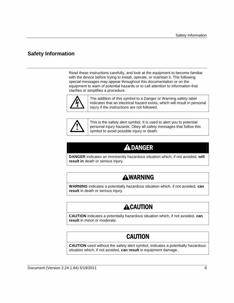
Read these instructions carefully, and look at the equipment to become familiar with the device before trying to install, operate, or maintain it. The following special messages may appear throughout this documentation or on the equipment to warn of potential hazards or to call attention to information that clarifies or simplifies a procedure.
The addition of this symbol to a Danger or Warning safety label indicates that an electrical hazard exists, which will result in personal injury if the instructions are not followed.
This is the safety alert symbol. It is used to alert you to potential personal injury hazards. Obey all safety messages that follow this symbol to avoid possible injury or death.
DANGER
DANGER indicates an imminently hazardous situation which, if not avoided, will result in death or serious injury.
WARNING
WARNING indicates a potentially hazardous situation which, if not avoided, can result in death or serious injury.
CAUTION
CAUTION indicates a potentially hazardous situation which, if not avoided, can result in minor or moderate.
CAUTION
CAUTION used without the safety alert symbol, indicates a potentially hazardous situation which, if not avoided, can result in equipment damage..
Safety Information
Document (Version 2.24.1.84) 5/19/2011 7 7
PLEASE NOTE
Electrical equipment should be installed, operated, serviced, and maintained only by qualified personnel. No responsibility is assumed by Schneider Electric for any consequences arising out of the use of this material.
A qualified person is one who has skills and knowledge related to the construction and operation of electrical equipment and the installation, and has received safety training to recognize and avoid the hazards involved.
BEFORE YOU BEGIN
Do not use this product on machinery lacking effective point-of-operation guarding. Lack of effective point-of-operation guarding on a machine can result in serious injury to the operator of that machine.
CAUTION
EQUIPMENT OPERATION HAZARD
Verify that all installation and set up procedures have been completed.
Before operational tests are performed, remove all blocks or other temporary holding means used for shipment from all component devices.
Remove tools, meters, and debris from equipment.
Failure to follow these instructions can result in injury or equipment damage.
Follow all start-up tests recommended in the equipment documentation. Store all equipment documentation for future references.
Software testing must be done in both simulated and real environments.
Verify that the completed system is free from all short circuits and grounds, except those grounds installed according to local regulations (according to the National Electrical Code in the U.S.A, for instance). If high-potential voltage testing is necessary, follow recommendations in equipment documentation to prevent accidental equipment damage.
Before energizing equipment:
Remove tools, meters, and debris from equipment.
Close the equipment enclosure door.
Remove ground from incoming power lines.
Perform all start-up tests recommended by the manufacturer.
OPERATION AND ADJUSTMENTS
The following precautions are from the NEMA Standards Publication ICS 7.1-1995 (English version prevails):
Safety Information
Document (Version 2.24.1.84) 5/19/2011 8 8
Regardless of the care exercised in the design and manufacture of equipment or in the selection and ratings of components, there are hazards that can be encountered if such equipment is improperly operated.
It is sometimes possible to misadjust the equipment and thus produce unsatisfactory or unsafe operation. Always use the manufacturer’s instructions as a guide for functional adjustments. Personnel who have access to these adjustments should be familiar with the equipment manufacturer’s instructions and the machinery used with the electrical equipment.
Only those operational adjustments actually required by the operator should be accessible to the operator. Access to other controls should be restricted to prevent unauthorized changes in operating characteristics.
About The Book
Document (Version 2.24.1.84) 5/19/2011 9 9
About The Book
At a Glance
Document Scope
This manual describes the 5607 Input/Output (I/O) module.
Validity Notes
This document is valid for all versions of the 5607 Input/Output (I/O) module.
Product Related Information
WARNING
UNINTENDED EQUIPMENT OPERATION
The application of this product requires expertise in the design and programming of control systems. Only persons with such expertise should be allowed to program, install, alter and apply this product.
Follow all local and national safety codes and standards.
Failure to follow these instructions can result in death, serious injury or equipment damage.
User Comments
We welcome your comments about this document. You can reach us by e-mail at [email protected].
Overview
Document (Version 2.24.1.84) 5/19/2011 10 10
Overview
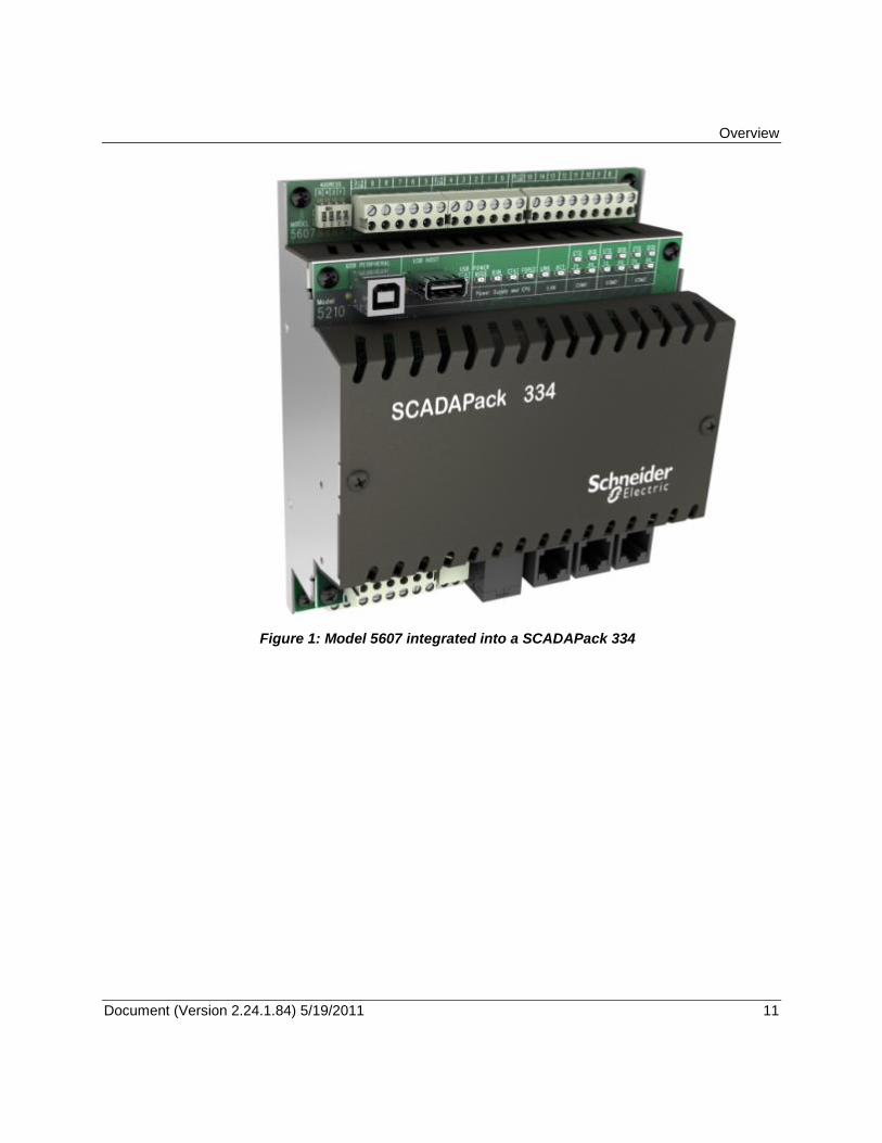
The 5607 Input / Output (I/O) module provides 8 analog inputs, 16 digital inputs and 10 relay digital outputs. In addition 2 analog outputs may optionally be added to the 5607 I/O module.
The 5607 I/O module is available as a standalone 5000 module that can be added to the I/O expansion bus for SCADAPack 32, SCADAPack 350 and SCADAPack 330 controllers. A maximum of 8 individually addressed 5607 I/I modules can be added to the I/O expansion bus.
The 5607 I/O module is also available as an integrated I/O module with the SCADAPack 330 controller. This product is the SCADAPack 334 controller.
The analog inputs are used with devices such as pressure, level, flow, and temperature transmitters; instrumentation such as pH and conductivity sensors; and other high-level analog signal sources. The 5607 input module measures current or voltage inputs in the ranges 0 to 20mA, 4-20mA, 0 to 5 V or 1 to 5 V. Each input is individually configured for input type and range. The 5607 module uses a 16-bit analog to digital (A/D) converter.
The 5607 I/O module analog inputs and outputs are transient suppressed and optically isolated from the main logic power. The inputs are single ended and share a common return.
The digital inputs are optically isolated from the logic power. To simplify field wiring, the inputs are grouped with eight inputs sharing a single common return. These groups of eight inputs are isolated from each other. Light emitting diodes show the status of each of the inputs. The digital inputs are available in two standard voltage ranges, for both AC and DC applications.
The 10 Form A (normally open) relay outputs can be used to control panel lamps, relays, solenoid valves, and other on/off devices. The relay outputs are well suited to applications that cannot tolerate any off-state leakage current, that require high load currents, or that involve non-standard voltages or current ranges.
This manual covers the powering, wiring and configuration of a 5607 I/O module only. It is meant to be used with the hardware manual of the respective SCADAPack controller to which the I/O module is attached.
Overview
Document (Version 2.24.1.84) 5/19/2011 11 11
Figure 1: Model 5607 integrated into a SCADAPack 334
Installation
Document (Version 2.24.1.84) 5/19/2011 12 12
Installation
The installation of the 5607 I/O module requires mounting the module on the 7.5mm by 35mm DIN rail and connecting the module to the system I/O Bus. Refer to the System Configuration Guide, at the beginning of this manual, for complete information on system layout, I/O Bus cable routing and module installation.
For ATEX and IECx applications only:
This equipment is to be installed in an enclosure certified for use, providing a degree of protection of IP54 or better. The free internal volume of the enclosure must be dimensioned in order to keep the temperature rating. A T4 rating is acceptable. For products using Solid State Relays (5415, 5606 and 5607 modules and SCADAPack using 5606 and 5607 modules) A T4 rating is acceptable for maximum loads of 2A. When 3A loads are connected to the Solid State Relays, the maximum ambient rating is lowered to 50°C in order to maintain the T4 rating.
Software Configuration
The 5607 I/O module is configured using Telepace or IEC 61131-3 application software.
For Telepace applications use the SCADAPack 5607 I/O Module register assignment to configure the 5607 I/O module. Modbus addresses for the analog inputs and outputs and the digital inputs and outputs are assigned using the register assignment.
For IEC 61131-3 applications use the sp5607 I/O connection to configure the 5607 I/O module.
Refer to the respective Telepace and IEC 61131-3 software manuals for information on using the above functions.
Field Wiring Connectors
The 5607 I/O module uses screw termination style connectors for termination of field wiring. These connectors accommodate solid or stranded wires from 12 to 22 AWG.
Remove power before servicing unit.
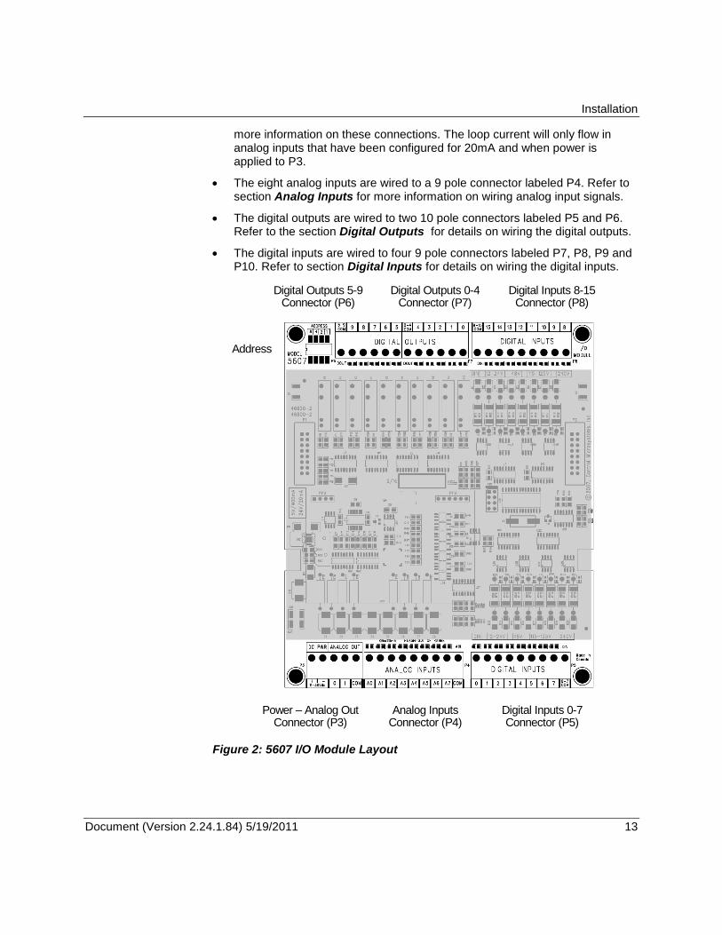
The 5607 I/O Module has six termination connectors for the connection of field wiring. Refer to Figure 2: 5607 I/O Module Layout for wiring connector locations.
Primary power input connections and optional analog output connections are wired to a 5 pole connector labeled P3. Refer to section Power Supply for
Installation
Document (Version 2.24.1.84) 5/19/2011 13 13
more information on these connections. The loop current will only flow in analog inputs that have been configured for 20mA and when power is applied to P3.
The eight analog inputs are wired to a 9 pole connector labeled P4. Refer to section Analog Inputs for more information on wiring analog input signals.
The digital outputs are wired to two 10 pole connectors labeled P5 and P6. Refer to the section Digital Outputs for details on wiring the digital outputs.
The digital inputs are wired to four 9 pole connectors labeled P7, P8, P9 and P10. Refer to section Digital Inputs for details on wiring the digital inputs.
Digital Inputs 8-15 Connector (P8)
Digital Inputs 0-7 Connector (P5)
Power – Analog Out Connector (P3)
Analog Inputs Connector (P4)
Digital Outputs 0-4 Connector (P7)
Digital Outputs 5-9 Connector (P6)
Address
Figure 2: 5607 I/O Module Layout
Power Supply
Document (Version 2.24.1.84) 5/19/2011 14 14
Power Supply
Overview and Requirements
The 5607 I/O module requires a nominally 12V or 24V DC power supply applied to the terminals labeled 11-30V on connector P3 to power the analog input and optional analog output circuitry.
The current requirement of the analog portion (input and optional output circuitry) on the 5607 I/O board can vary from a minimum of 12mA for basic operation of the analog circuitry plus an additional 40mA for the optional analog outputs.
The 5607 module also require 5V from the system 5V power supply. This power is generally provided by the system controller which provides 5V through the I/O Bus cable. Refer to the Specifications section of the controller manual for the power capabilities of the controller. This may also be provided by a 5103 power supply module.
Power for the I/O board is generally provided as follows:
A 24Vdc source connected to the DC PWR terminals on the controller board and on the 5607 I/O module in a parallel configuration. See section Recommended 24V Power Supply Configuration for an example on this wiring configuration.
Power for the 5607 I/O board can be provided in other configurations as follows:
AC powered controllers, with a 16Vac source supplying power to the controller board, 24V is available on the DC PWR terminals of the controller board which can be used to power the lower I/O model. Refer to the Hardware manual of the controller modules for an example on this wiring configuration.
With a 12Vdc source connected to the DC PWR terminals on the controller board and on the 5607 I/O module in a parallel configuration. Refer to the Hardware manual of the controller modules for an example on this wiring configuration.
A 5103 UPS Power Supply supplies 5Vdc to the controller board through the IMC cable and supplies 24Vdc to the 5607 I/O module through the 24Vdc output. Refer to the Hardware manual of the controller modules for an example on this wiring configuration.
Recommended 24V Power Supply Configuration
This configuration uses a 24V power supply to power the controller board and the 5607 I/O module. This 24V is used to power the analog circuitry for the analog on the 5607 I/O module.
Power Supply
Document (Version 2.24.1.84) 5/19/2011 15 15
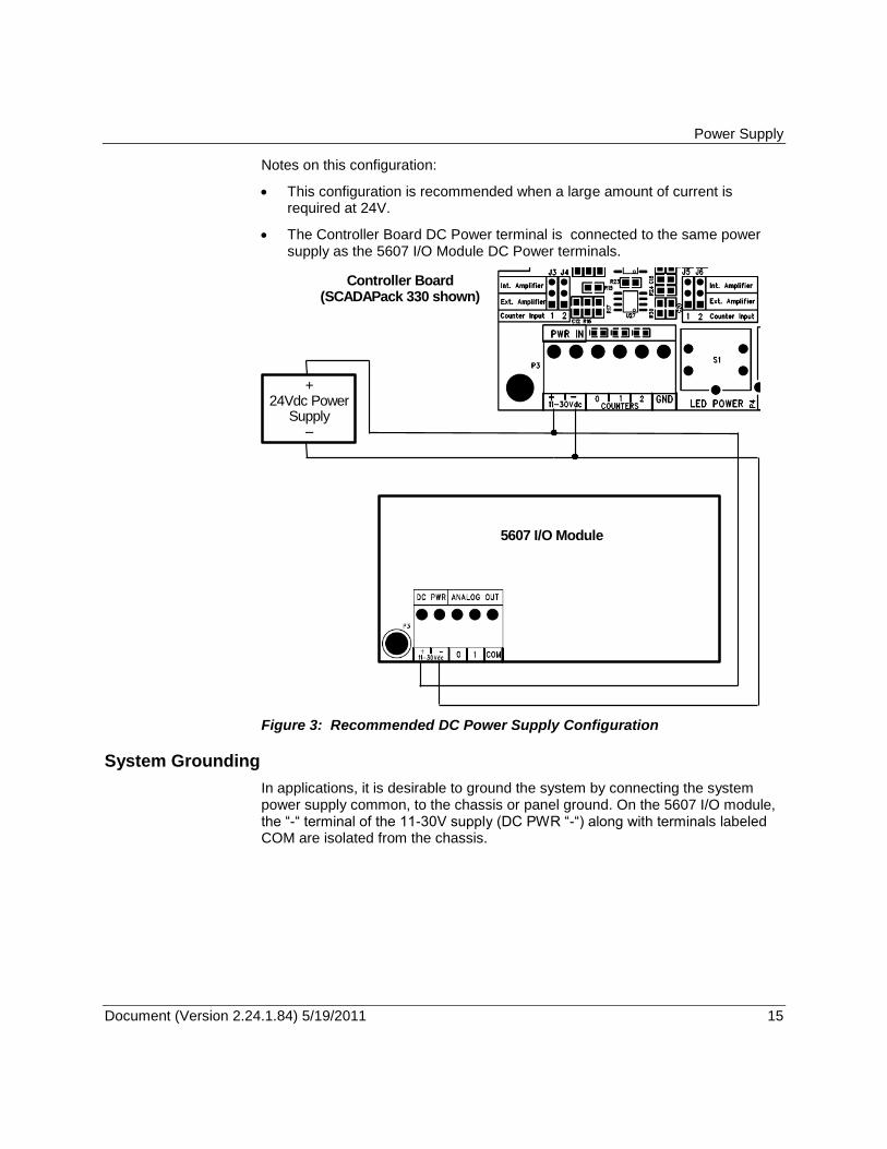
Notes on this configuration:
This configuration is recommended when a large amount of current is required at 24V.
The Controller Board DC Power terminal is connected to the same power supply as the 5607 I/O Module DC Power terminals.
+ 24Vdc Power
Supply –
5607 I/O Module
Controller Board (SCADAPack 330 shown)
Figure 3: Recommended DC Power Supply Configuration
System Grounding
In applications, it is desirable to ground the system by connecting the system power supply common, to the chassis or panel ground. On the 5607 I/O module, the ―-― terminal of the 11-30V supply (DC PWR ―-―) along with terminals labeled COM are isolated from the chassis.
DIP Switch Settings
Document (Version 2.24.1.84) 5/19/2011 16 16
DIP Switch Settings
Address Selection
The 5000 I/O bus supports a maximum of 20 I/O (input/output) modules. 5000 I/O module types may be combined in any manner to the maximum supported by the controller used.
Each type of I/O module, connected to the I/O bus, has a unique I/O module address. Different types of I/O modules may have the same module address. The 5607 and the 5606 I/O modules share the same address, i.e. they are treated as the same module type. A 5607 and a 5606 need to have different module addresses if they share the same I/O bus.
The address range supported by the controller module may restrict the I/O module address range. Refer to the controller manual for the maximum address supported.
5607 Addressing
Three address switches on the 5607 labeled 4, 2, and 1 set the address. A 5607 I/O module that is installed in a SCADAPack is generally set to address 0. Address 0 can be used if there is no 5607 installed in a SCADAPack. A second 5607 is generally set to address 1.
Note that the 5607 and the 5606 I/O modules share the same address, i.e. they are treated as the same module type. A 5607 and a 5606 must have different module addresses if they share the same I/O bus.
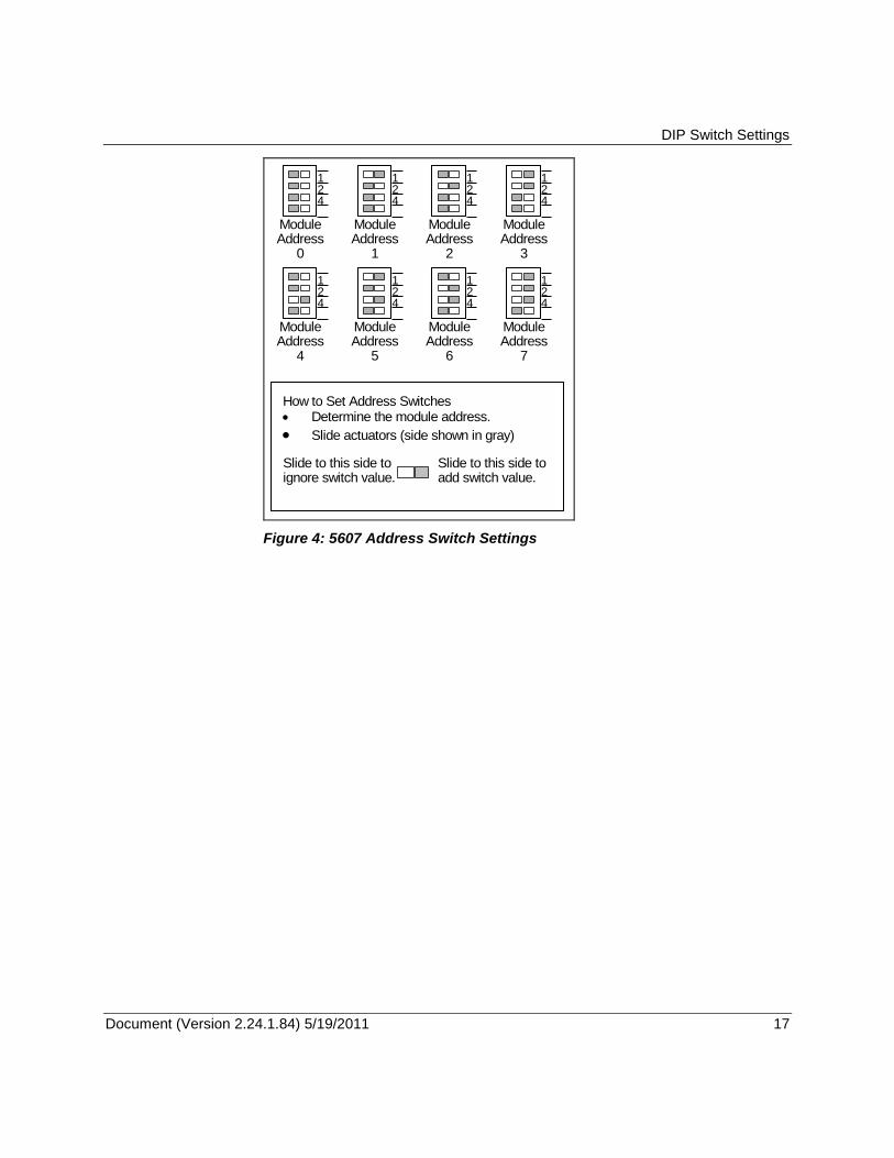
To set the address:
Open the four switches by sliding the actuators to the ―OFF‖ position.
Close the switches that total to the desired address by sliding the actuators to ―ON‖. Switch settings for each of the 8 module addresses are shown in the figure below.
DIP Switch Settings
Document (Version 2.24.1.84) 5/19/2011 17 17
ModuleAddress
0
21
4
How to Set Address Switches Determine the module address.
Slide actuators (side shown in gray)
Slide to this side toignore switch value.
ModuleAddress
1
21
4
ModuleAddress
2
21
4
ModuleAddress
3
21
4
ModuleAddress
4
21
4
ModuleAddress
5
21
4
ModuleAddress
6
21
4
ModuleAddress
7
21
4
Slide to this side toadd switch value.
Figure 4: 5607 Address Switch Settings
Analog Inputs
Document (Version 2.24.1.84) 5/19/2011 18 18
Analog Inputs
The 5607 I/O module provides eight single ended analog inputs on connector P4. Refer to Figure 2: 5607 I/O Module Layout for the location of this connector.
Analog inputs can be configured for current or voltage mode via software. Please refer to the section Current or Voltage Mode below on how to choose input modes.
In voltage mode, these analog inputs are single ended with a measurement range of 0-5V or 0-10V. The range is selected via software.
In current mode, a 250 current sense resistor appears across each analog input channel. Measurement range in current mode is 0-20mA or 4-20mA
selectable via software. The 250 resistor produces a voltage drop (input reading) of 5V for a 20mA of current flow.
In current mode a 250 resistor appears across the analog input channel. In voltage mode, input channels are high impedance.
The analog inputs use a 16-bit successive approximation digital to analog (A/D) converter.
By default analog inputs are configured for voltage mode with measurement range of 0-5V.
Current or Voltage Mode
The analog inputs can be configured for either voltage or current mode via software. When assigning the registers in Telepace or setting up an I/O connection in IEC 61131-3, the user is given an opportunity to select the mode of operation.
For Telepace applications use the SCADAPack 5607 I/O Module register assignment to configure the mode for each analog input. The register assignment is also used to assign the analog input data to Modbus registers.
For IEC 61131-3 applications use the sp5607 I/O connection to configure the mode for each analog input.
Refer to the respective Telepace and IEC 61131-3 software manuals for information on using the above functions.
This module should be the only loop current measurement device in the loop when using the analog inputs in the 20mA measurement mode.
If power to the module is removed, the module reverts to voltage mode and in-effect opens the current loop.
When power is restored the module returns to the user configured mode. Applications that cannot tolerate this possibility require external current sense resistors, and with the module input range set to voltage.
Analog Inputs
Document (Version 2.24.1.84) 5/19/2011 19 19
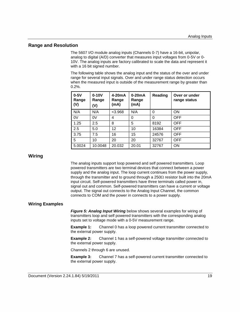
Range and Resolution
The 5607 I/O module analog inputs (Channels 0-7) have a 16-bit, unipolar, analog to digital (A/D) converter that measures input voltages from 0-5V or 0-10V. The analog inputs are factory calibrated to scale the data and represent it with a 16 bit signed number.
The following table shows the analog input and the status of the over and under range for several input signals. Over and under range status detection occurs when the measured input is outside of the measurement range by greater than 0.2%.
0-5V Range (V)
0-10V Range
(V)
4-20mA Range (mA)
0-20mA Range (mA)
Reading Over or under range status
N/A N/A <3.968 N/A 0 ON
0V 0V 4 0 0 OFF
1.25 2.5 8 5 8192 OFF
2.5 5.0 12 10 16384 OFF
3.75 7.5 16 15 24576 OFF
5 10 20 20 32767 OFF
5.0024 10.0048 20.032 20.01 32767 ON
Wiring
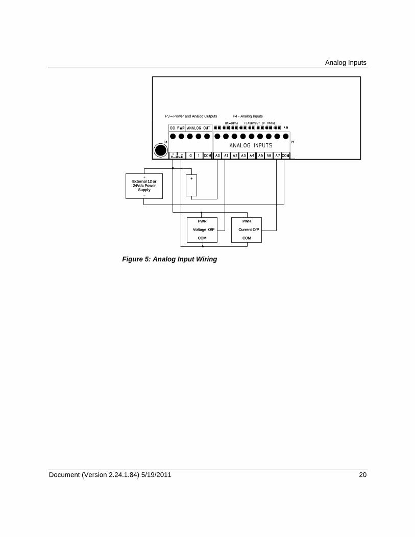
The analog inputs support loop powered and self powered transmitters. Loop powered transmitters are two terminal devices that connect between a power supply and the analog input. The loop current continues from the power supply,
through the transmitter and to ground through a 250 resistor built into the 20mA input circuit. Self-powered transmitters have three terminals called power in, signal out and common. Self-powered transmitters can have a current or voltage output. The signal out connects to the Analog Input Channel, the common connects to COM and the power in connects to a power supply.
Wiring Examples
Figure 5: Analog Input Wiring below shows several examples for wiring of transmitters loop and self powered transmitters with the corresponding analog inputs set to voltage mode with a 0-5V measurement range.
Example 1: Channel 0 has a loop powered current transmitter connected to the external power supply.
Example 2: Channel 1 has a self-powered voltage transmitter connected to the external power supply.
Channels 2 through 6 are unused.
Example 3: Channel 7 has a self-powered current transmitter connected to the external power supply.
Analog Inputs
Document (Version 2.24.1.84) 5/19/2011 20 20
+ External 12 or 24Vdc Power
Supply _
+
_
P4 - Analog Inputs
PWR
Voltage O/P
COM
PWR
Current O/P
COM
P3 – Power and Analog Outputs
Figure 5: Analog Input Wiring
Analog Outputs
Document (Version 2.24.1.84) 5/19/2011 21 21
Analog Outputs
The 5607 I/O Module may include two channels of analog output if this option was requested at time of purchase.
For Telepace applications use the SCADAPack 5607 I/O Module register assignment to write to the two analog outputs.
For IEC 61131-3 applications use the sp5607 I/O connection to write to the two analog outputs.
Refer to the respective Telepace and IEC 61131-3 software manuals for information on using the above functions.
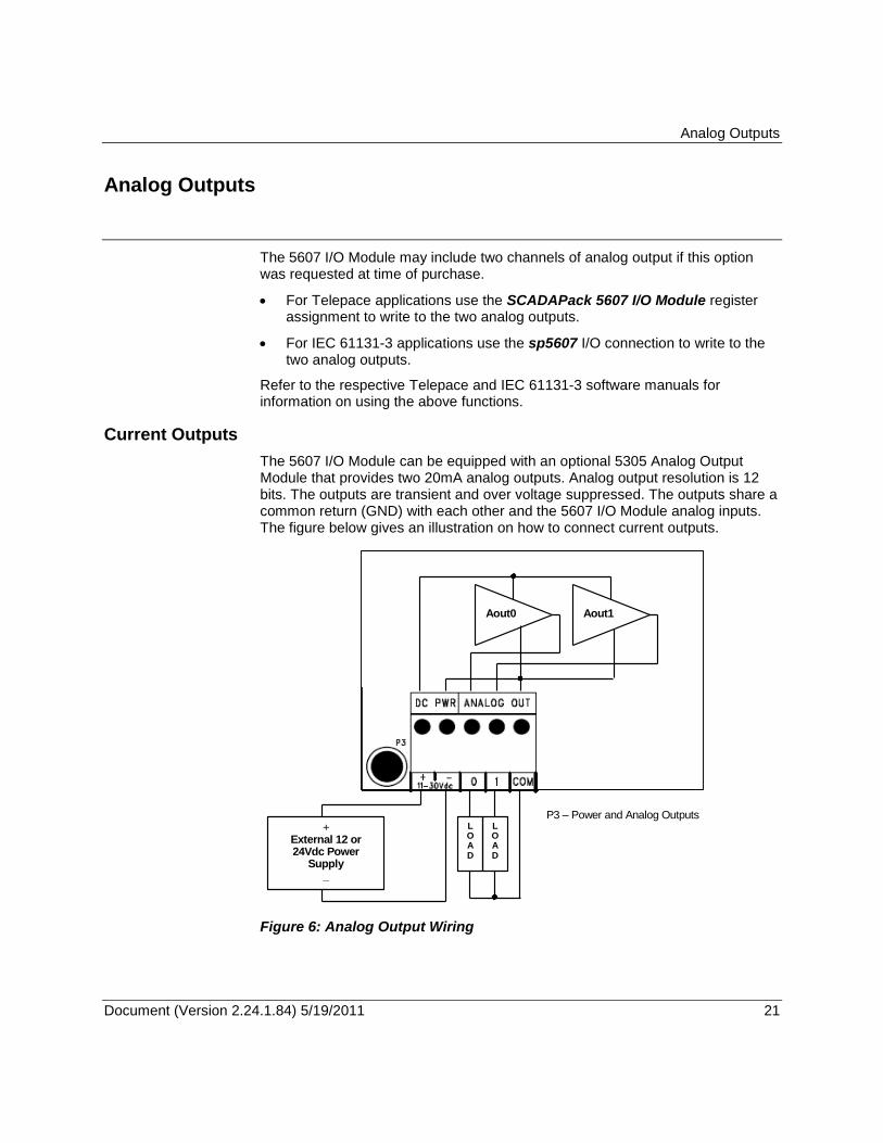
Current Outputs
The 5607 I/O Module can be equipped with an optional 5305 Analog Output Module that provides two 20mA analog outputs. Analog output resolution is 12 bits. The outputs are transient and over voltage suppressed. The outputs share a common return (GND) with each other and the 5607 I/O Module analog inputs. The figure below gives an illustration on how to connect current outputs.
P3 – Power and Analog Outputs +
External 12 or 24Vdc Power
Supply _
L O A D
L O A D
Aout0 Aout1
Figure 6: Analog Output Wiring
Analog Outputs
Document (Version 2.24.1.84) 5/19/2011 22 22
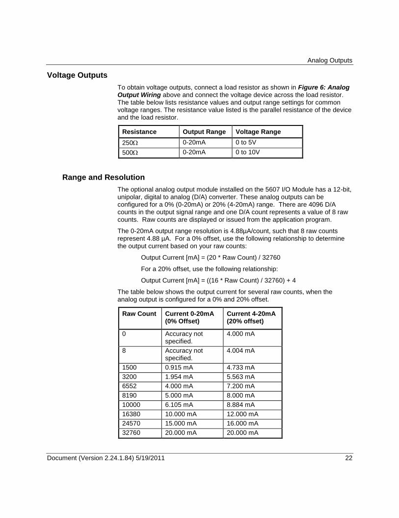
Voltage Outputs
To obtain voltage outputs, connect a load resistor as shown in Figure 6: Analog Output Wiring above and connect the voltage device across the load resistor. The table below lists resistance values and output range settings for common voltage ranges. The resistance value listed is the parallel resistance of the device and the load resistor.
Resistance Output Range Voltage Range
250 0-20mA 0 to 5V
500 0-20mA 0 to 10V
Range and Resolution
The optional analog output module installed on the 5607 I/O Module has a 12-bit, unipolar, digital to analog (D/A) converter. These analog outputs can be configured for a 0% (0-20mA) or 20% (4-20mA) range. There are 4096 D/A counts in the output signal range and one D/A count represents a value of 8 raw counts. Raw counts are displayed or issued from the application program.
The 0-20mA output range resolution is 4.88µA/count, such that 8 raw counts represent 4.88 µA. For a 0% offset, use the following relationship to determine the output current based on your raw counts:
Output Current [mA] = (20 * Raw Count) / 32760
For a 20% offset, use the following relationship:
Output Current [mA] = ((16 * Raw Count) / 32760) + 4
The table below shows the output current for several raw counts, when the analog output is configured for a 0% and 20% offset.
Raw Count
Current 0-20mA (0% Offset)
Current 4-20mA (20% offset)
0 Accuracy not specified.
4.000 mA
8 Accuracy not specified.
4.004 mA
1500 0.915 mA 4.733 mA
3200 1.954 mA 5.563 mA
6552 4.000 mA 7.200 mA
8190 5.000 mA 8.000 mA
10000 6.105 mA 8.884 mA
16380 10.000 mA 12.000 mA
24570 15.000 mA 16.000 mA
32760 20.000 mA 20.000 mA
Digital Inputs
Document (Version 2.24.1.84) 5/19/2011 23 23
Digital Inputs
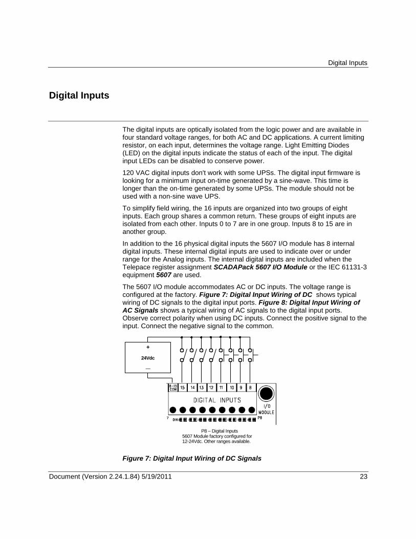
The digital inputs are optically isolated from the logic power and are available in four standard voltage ranges, for both AC and DC applications. A current limiting resistor, on each input, determines the voltage range. Light Emitting Diodes (LED) on the digital inputs indicate the status of each of the input. The digital input LEDs can be disabled to conserve power.
120 VAC digital inputs don't work with some UPSs. The digital input firmware is looking for a minimum input on-time generated by a sine-wave. This time is longer than the on-time generated by some UPSs. The module should not be used with a non-sine wave UPS.
To simplify field wiring, the 16 inputs are organized into two groups of eight inputs. Each group shares a common return. These groups of eight inputs are isolated from each other. Inputs 0 to 7 are in one group. Inputs 8 to 15 are in another group.
In addition to the 16 physical digital inputs the 5607 I/O module has 8 internal digital inputs. These internal digital inputs are used to indicate over or under range for the Analog inputs. The internal digital inputs are included when the Telepace register assignment SCADAPack 5607 I/O Module or the IEC 61131-3 equipment 5607 are used.
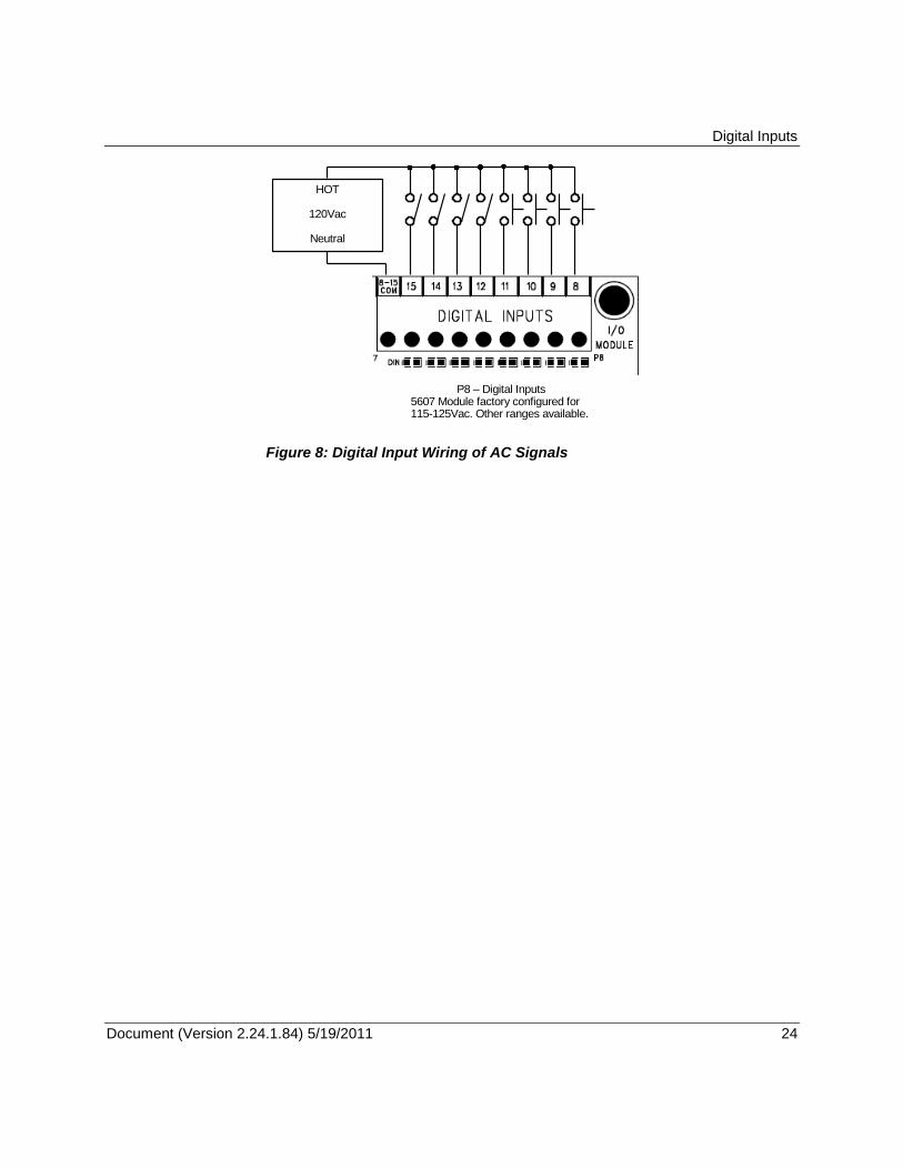
The 5607 I/O module accommodates AC or DC inputs. The voltage range is configured at the factory. Figure 7: Digital Input Wiring of DC shows typical wiring of DC signals to the digital input ports. Figure 8: Digital Input Wiring of AC Signals shows a typical wiring of AC signals to the digital input ports. Observe correct polarity when using DC inputs. Connect the positive signal to the input. Connect the negative signal to the common.
P8 – Digital Inputs 5607 Module factory configured for 12-24Vdc. Other ranges available.
+
24Vdc
—
Figure 7: Digital Input Wiring of DC Signals
Digital Inputs
Document (Version 2.24.1.84) 5/19/2011 24 24
P8 – Digital Inputs 5607 Module factory configured for 115-125Vac. Other ranges available.
HOT
120Vac
Neutral
Figure 8: Digital Input Wiring of AC Signals
Digital Outputs
Document (Version 2.24.1.84) 5/19/2011 25 25
Digital Outputs
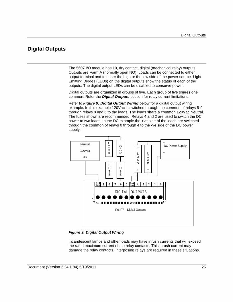
The 5607 I/O module has 10, dry contact, digital (mechanical relay) outputs. Outputs are Form A (normally open NO). Loads can be connected to either output terminal and to either the high or the low side of the power source. Light Emitting Diodes (LEDs) on the digital outputs show the status of each of the outputs. The digital output LEDs can be disabled to conserve power.
Digital outputs are organized in groups of five. Each group of five shares one common. Refer the Digital Outputs section for relay current limitations.
Refer to Figure 9: Digital Output Wiring below for a digital output wiring example. In this example 120Vac is switched through the common of relays 5-9 through relays 8 and 6 to the loads. The loads share a common 120Vac Neutral. The fuses shown are recommended. Relays 4 and 2 are used to switch the DC power to two loads. In the DC example the +ve side of the loads are switched through the common of relays 0 through 4 to the -ve side of the DC power supply.
Neutral
120Vac
Hot
P6, P7 – Digital Outputs
– DC Power Supply
+
L O A D
F U S E
L O A D
F U S E
– L O A D +
– L O A D +
Figure 9: Digital Output Wiring
Incandescent lamps and other loads may have inrush currents that will exceed the rated maximum current of the relay contacts. This inrush current may damage the relay contacts. Interposing relays are required in these situations.
Digital Outputs
Document (Version 2.24.1.84) 5/19/2011 26 26
When controlling inductive loads with digital outputs the energy stored in the coil is capable of generating significant electrical noise when the relay contacts are opened. This noise can be suppressed using a diode across the coil in DC circuits or using a MOV (varistor) across the coil in AC circuits.
Solid State Relay Version
The Model 5607 is optionally available with solid state relays (SSR). Refer to the Digital Outputs section for limitations associated with using solid state relays.
Observe correct polarity of the load voltages when using the SSR version of the 5607. The loads must be connected to the -ve side of the power supply and the +ve side of the power must be switched through the COM terminal as shown in example above.
Operation and Maintenance
Document (Version 2.24.1.84) 5/19/2011 27 27
Operation and Maintenance
LED Indicators
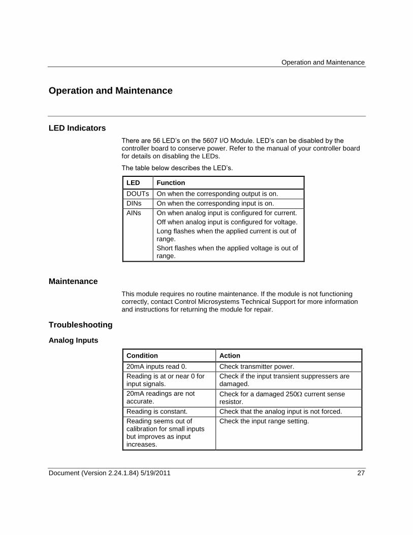
There are 56 LED’s on the 5607 I/O Module. LED’s can be disabled by the controller board to conserve power. Refer to the manual of your controller board for details on disabling the LEDs.
The table below describes the LED’s.
LED Function
DOUTs On when the corresponding output is on.
DINs On when the corresponding input is on.
AINs On when analog input is configured for current.
Off when analog input is configured for voltage.
Long flashes when the applied current is out of range.
Short flashes when the applied voltage is out of range.
Maintenance
This module requires no routine maintenance. If the module is not functioning correctly, contact Control Microsystems Technical Support for more information and instructions for returning the module for repair.
Troubleshooting
Analog Inputs
Condition Action
20mA inputs read 0. Check transmitter power.
Reading is at or near 0 for input signals.
Check if the input transient suppressers are damaged.
20mA readings are not accurate.
Check for a damaged 250 current sense resistor.
Reading is constant. Check that the analog input is not forced.
Reading seems out of calibration for small inputs but improves as input increases.
Check the input range setting.
Operation and Maintenance
Document (Version 2.24.1.84) 5/19/2011 28 28
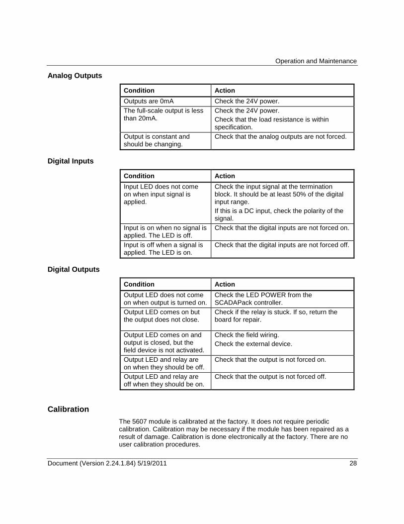
Analog Outputs
Condition Action
Outputs are 0mA Check the 24V power.
The full-scale output is less than 20mA.
Check the 24V power.
Check that the load resistance is within specification.
Output is constant and should be changing.
Check that the analog outputs are not forced.
Digital Inputs
Condition Action
Input LED does not come on when input signal is applied.
Check the input signal at the termination block. It should be at least 50% of the digital input range.
If this is a DC input, check the polarity of the signal.
Input is on when no signal is applied. The LED is off.
Check that the digital inputs are not forced on.
Input is off when a signal is applied. The LED is on.
Check that the digital inputs are not forced off.
Digital Outputs
Condition Action
Output LED does not come on when output is turned on.
Check the LED POWER from the SCADAPack controller.
Output LED comes on but the output does not close.
Check if the relay is stuck. If so, return the board for repair.
Output LED comes on and output is closed, but the field device is not activated.
Check the field wiring.
Check the external device.
Output LED and relay are on when they should be off.
Check that the output is not forced on.
Output LED and relay are off when they should be on.
Check that the output is not forced off.
Calibration
The 5607 module is calibrated at the factory. It does not require periodic calibration. Calibration may be necessary if the module has been repaired as a result of damage. Calibration is done electronically at the factory. There are no user calibration procedures.
Specifications
Document (Version 2.24.1.84) 5/19/2011 29 29
Specifications
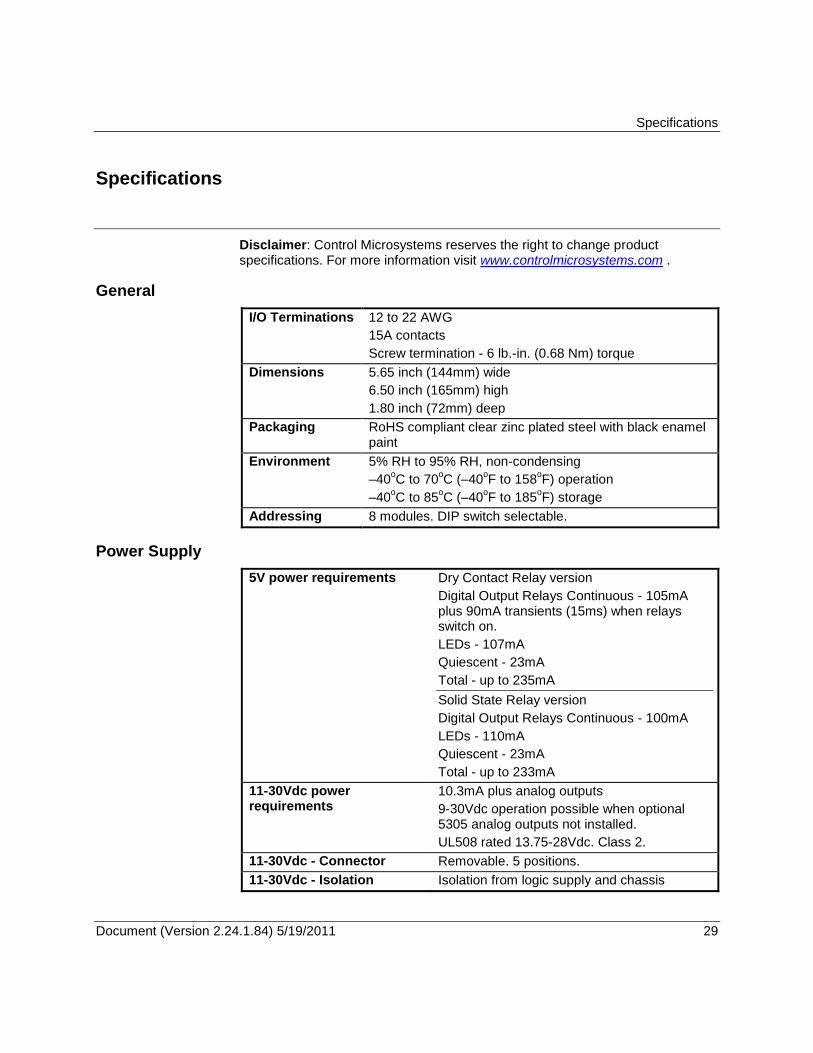
Disclaimer: Control Microsystems reserves the right to change product specifications. For more information visit www.controlmicrosystems.com .
General
I/O Terminations 12 to 22 AWG
15A contacts
Screw termination - 6 lb.-in. (0.68 Nm) torque
Dimensions
5.65 inch (144mm) wide
6.50 inch (165mm) high
1.80 inch (72mm) deep
Packaging RoHS compliant clear zinc plated steel with black enamel paint
Environment 5% RH to 95% RH, non-condensing
–40oC to 70
oC (–40
oF to 158
oF) operation
–40oC to 85
oC (–40
oF to 185
oF) storage
Addressing 8 modules. DIP switch selectable.
Power Supply
5V power requirements Dry Contact Relay version
Digital Output Relays Continuous - 105mA plus 90mA transients (15ms) when relays switch on.
LEDs - 107mA
Quiescent - 23mA
Total - up to 235mA
Solid State Relay version
Digital Output Relays Continuous - 100mA
LEDs - 110mA
Quiescent - 23mA
Total - up to 233mA
11-30Vdc power requirements
10.3mA plus analog outputs
9-30Vdc operation possible when optional 5305 analog outputs not installed.
UL508 rated 13.75-28Vdc. Class 2.
11-30Vdc - Connector Removable. 5 positions.
11-30Vdc - Isolation Isolation from logic supply and chassis
Specifications
Document (Version 2.24.1.84) 5/19/2011 30 30
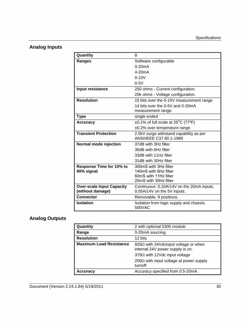
Analog Inputs
Quantity 8
Ranges Software configurable
0-20mA
4-20mA
0-10V
0-5V
Input resistance 250 ohms - Current configuration.
20k ohms - Voltage configuration.
Resolution 15 bits over the 0-10V measurement range
14 bits over the 0-5V and 0-20mA measurement range.
Type single ended
Accuracy ±0.1% of full scale at 25oC (77ºF)
±0.2% over temperature range
Transient Protection 2.5kV surge withstand capability as per ANSI/IEEE C37.90.1-1989
Normal mode rejection 37dB with 3Hz filter
35dB with 6Hz filter
33dB with 11Hz filter
31dB with 30Hz filter
Response Time for 10% to 90% signal
300mS with 3Hz filter 140mS with 6Hz filter 60mS with 11Hz filter 20mS with 30Hz filter
Over-scale Input Capacity (without damage)
Continuous: 0.10A/14V on the 20mA inputs. 0.05A/14V on the 5V inputs.
Connector Removable. 9 positions.
Isolation Isolation from logic supply and chassis. 500VAC
Analog Outputs
Quantity 2 with optional 5305 module
Range 0-20mA sourcing
Resolution 12 bits
Maximum Load Resistance 925 with 24Vdcinput voltage or when internal 24V power supply is on.
375 with 12Vdc input voltage
250 with input voltage at power supply turnoff
Accuracy Accuracy specified from 0.5-20mA.
Specifications
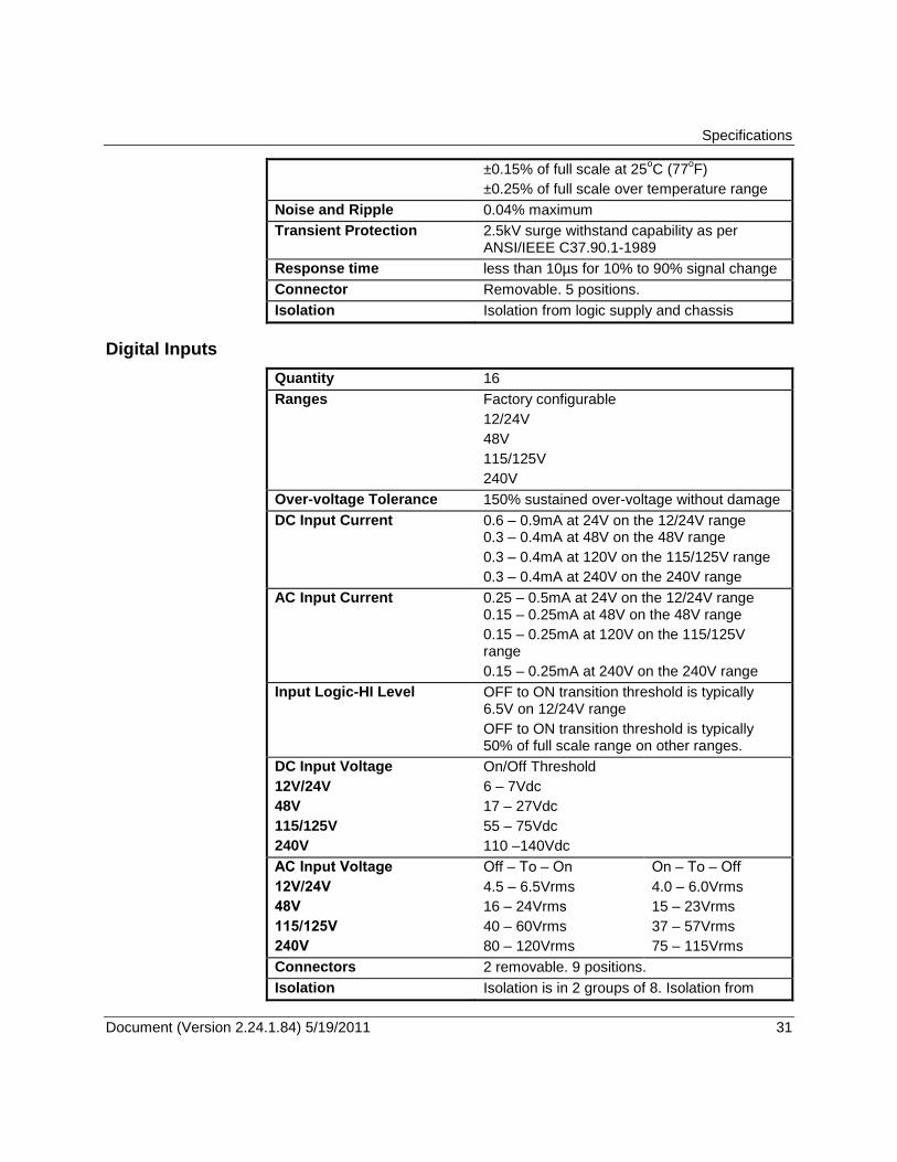
Document (Version 2.24.1.84) 5/19/2011 31 31
±0.15% of full scale at 25oC (77
oF)
±0.25% of full scale over temperature range
Noise and Ripple 0.04% maximum
Transient Protection 2.5kV surge withstand capability as per ANSI/IEEE C37.90.1-1989
Response time less than 10µs for 10% to 90% signal change
Connector Removable. 5 positions.
Isolation Isolation from logic supply and chassis
Digital Inputs
Quantity 16
Ranges Factory configurable
12/24V
48V
115/125V
240V
Over-voltage Tolerance 150% sustained over-voltage without damage
DC Input Current 0.6 – 0.9mA at 24V on the 12/24V range 0.3 – 0.4mA at 48V on the 48V range
0.3 – 0.4mA at 120V on the 115/125V range
0.3 – 0.4mA at 240V on the 240V range
AC Input Current 0.25 – 0.5mA at 24V on the 12/24V range 0.15 – 0.25mA at 48V on the 48V range
0.15 – 0.25mA at 120V on the 115/125V range
0.15 – 0.25mA at 240V on the 240V range
Input Logic-HI Level OFF to ON transition threshold is typically 6.5V on 12/24V range
OFF to ON transition threshold is typically 50% of full scale range on other ranges.
DC Input Voltage
12V/24V
48V
115/125V
240V
On/Off Threshold
6 – 7Vdc
17 – 27Vdc
55 – 75Vdc
110 –140Vdc
AC Input Voltage
12V/24V
48V
115/125V
240V
Off – To – On
4.5 – 6.5Vrms
16 – 24Vrms
40 – 60Vrms
80 – 120Vrms
On – To – Off
4.0 – 6.0Vrms
15 – 23Vrms
37 – 57Vrms
75 – 115Vrms
Connectors 2 removable. 9 positions.
Isolation Isolation is in 2 groups of 8. Isolation from
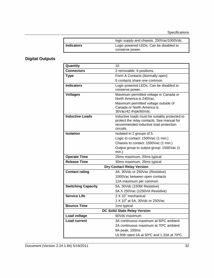
Specifications
Document (Version 2.24.1.84) 5/19/2011 32 32
logic supply and chassis. 250Vac/1000Vdc.
Indicators Logic powered LEDs. Can be disabled to conserve power.
Digital Outputs
Quantity 10
Connectors 2 removable. 6 positions.
Type Form A Contacts (Normally open)
5 contacts share one common
Indicators Logic powered LEDs. Can be disabled to conserve power.
Voltages Maximum permitted voltage in Canada or North America is 240Vac.
Maximum permitted voltage outside of Canada or North America is 30Vac/42.4Vpk/60Vdc.
Inductive Loads Inductive loads must be suitably protected to protect the relay contacts. See manual for recommended inductive load protection circuits.
Isolation Isolated in 2 groups of 5.
Logic to contact: 1500Vac (1 min.)
Chassis to contact: 1500Vac (1 min.)
Output group to output group: 1500Vac (1 min.)
Operate Time 25ms maximum, 20ms typical
Release Time 30ms maximum, 25ms typical
Dry Contact Relay Version
Contact rating 3A, 30Vdc or 250Vac (Resistive)
1000Vac between open contacts
12A maximum per common
Switching Capacity 5A, 30Vdc (150W Resistive)
5A X 250Vac (1250VA Resistive)
Service Life 2 X 10⁷ mechanical
1 X 10⁵ at 5A, 30Vdc or 250Vac
Bounce Time 1ms typical
DC Solid State Relay Version
Load voltage 60Vdc maximum
Load current 3A continuous maximum at 50ºC ambient
2A continuous maximum at 70ºC ambient
9A peak, 100ms
UL508 rated 2A at 50ºC and 1.33A at 70ºC.
Specifications
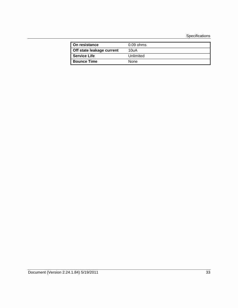
Document (Version 2.24.1.84) 5/19/2011 33 33
On resistance 0.09 ohms
Off state leakage current 10uA
Service Life Unlimited
Bounce Time None
Approvals and Certifications
Document (Version 2.24.1.84) 5/19/2011 34 34
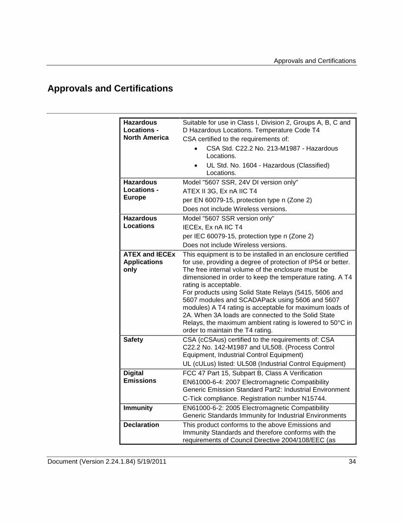
Approvals and Certifications
Hazardous Locations - North America
Suitable for use in Class I, Division 2, Groups A, B, C and D Hazardous Locations. Temperature Code T4
CSA certified to the requirements of:
CSA Std. C22.2 No. 213-M1987 - Hazardous Locations.
UL Std. No. 1604 - Hazardous (Classified) Locations.
Hazardous Locations - Europe
Model "5607 SSR, 24V DI version only"
ATEX II 3G, Ex nA IIC T4
per EN 60079-15, protection type n (Zone 2)
Does not include Wireless versions.
Hazardous Locations
Model "5607 SSR version only"
IECEx, Ex nA IIC T4
per IEC 60079-15, protection type n (Zone 2)
Does not include Wireless versions.
ATEX and IECEx Applications only
This equipment is to be installed in an enclosure certified for use, providing a degree of protection of IP54 or better. The free internal volume of the enclosure must be dimensioned in order to keep the temperature rating. A T4 rating is acceptable. For products using Solid State Relays (5415, 5606 and 5607 modules and SCADAPack using 5606 and 5607 modules) A T4 rating is acceptable for maximum loads of 2A. When 3A loads are connected to the Solid State Relays, the maximum ambient rating is lowered to 50°C in order to maintain the T4 rating.
Safety CSA (cCSAus) certified to the requirements of: CSA C22.2 No. 142-M1987 and UL508. (Process Control Equipment, Industrial Control Equipment)
UL (cULus) listed: UL508 (Industrial Control Equipment)
Digital Emissions
FCC 47 Part 15, Subpart B, Class A Verification
EN61000-6-4: 2007 Electromagnetic Compatibility Generic Emission Standard Part2: Industrial Environment
C-Tick compliance. Registration number N15744.
Immunity EN61000-6-2: 2005 Electromagnetic Compatibility Generic Standards Immunity for Industrial Environments
Declaration This product conforms to the above Emissions and Immunity Standards and therefore conforms with the requirements of Council Directive 2004/108/EEC (as
Approvals and Certifications
Document (Version 2.24.1.84) 5/19/2011 35 35
amended) relating to electromagnetic compatibility and is eligible to bear the CE mark.
The Low Voltage Directive 2006/95/EC applies to devices operating within 75 to 1500 VDC and/or 50 to 1000 VAC. This Directive is not applicable to this product when installed according to our specifications.