Embed Size (px)
Citation preview

VITODENS 200-W
Gas-fired wall-mounted condensing boiler
31 to 370 MBH / 9 to 105 kW
Multi-boiler installation 320 to 1480 MBH/
Vitodens 200-W
WB2B Series
Gas-Fired Wall-Mounted Condensing Boiler
with modulating MatriX cylinder burner
for room air independent operation
(using a direct vent system) or room air
dependent operation
For Natural Gas and Liquid Propane Gas
Heating input 31 to 370 MBH
for NG and LPG 9 to 105 kW
Technical Data ManualModel Nos. and pricing: see Price List
This trademark is registered with the U.S. Patent and Trademark Office.
5369 295 v1.5 09/2012

Product Information
2
VITODENS 200-W
Equipped with the industry’s first intelligent
combustion management system and
powerful control technology, the new
generation Vitodens 200-W gas-fired
wall-mount condensing boiler delivers
unparalleled performance, reliability and
comfort.
The benefits at a glance:
�Best value in its class with new
industry-leading technology and the most
standard features.
�Highest Efficiency up to 98% at full
modulation and up to 96.1% A.F.U.E.
CSA thermal efficiency rating to ANSI
Z.21.13/CSA 4.9 of 94.5% (for model
WB2B 105 only). Energy Star and the
CSA Energy Performance are not
applicable for model WB2B 105.
�Lasting performance with industry-leading
Viessmann made SA240 316 Ti stainless
steel Inox-Radial heat exchanger
constructed to CSA B51 and ASME
Section IV.
�Low Emission Combustion with Viessmann
made stainless steel MatriX cylinder
burner. Factory calibrated.
�Fast Installation and Reduced Maintenance
with Lambda Pro, industry-first intelligent
combustion management system: Adjusts
automatically to gas type and quality. No
fuel conversion kit required.
�Powerful and User-friendly
Viessmann Vitotronic on-board
multi-function outdoor reset boiler and
system control for multi-temperature
space and DHW heating.
�Expanded Application Range with
increased capacity up to 370 MBH.
Multi-boiler installation up to 1480 MBH
with up to 4 boilers (models WB2B 45,
60, 80, 105).
�Greater Venting Flexibility with increased
vent length (up to 180 ft. / 55 m) and
multiple venting options.
- Horizontal or vertical sealed combustion
coaxial venting (factory supplied).
- Horizontal, vertical or hybrid sealed
combustion double-pipe venting (field
supplied).
- Horizontal or vertical single-wall venting
(field supplied).
�Compact, Esthetic Product Design
and zero clearance to combustibles.
�Extremely Quiet Operation; quieter than
most refrigerators.
�True High-Altitude Operation up to
10,000 ft. / 3,000 m with simple
electronic adjustment.
�Efficiency up to 98% through intensive
condensation. The flue gas temperature is
only approximately 9-27º F (5-15º C)
above boiler return temperature (see chart
below).
5369295v1.5
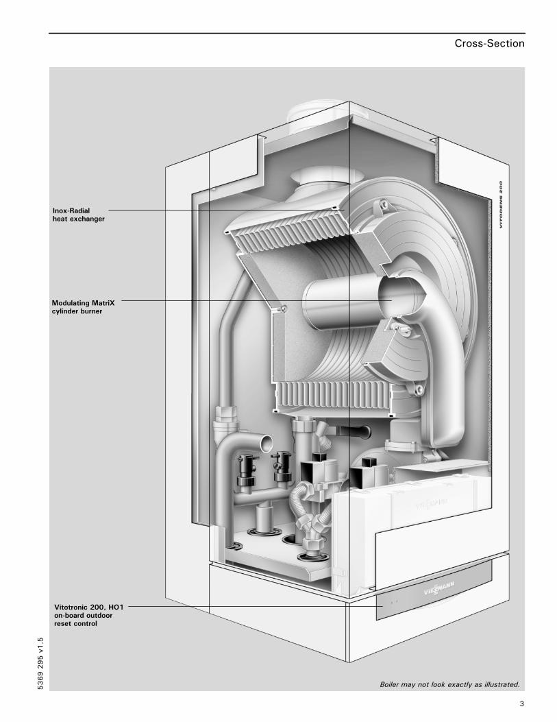
Inox-Radialheat exchanger
Modulating MatriXcylinder burner
Vitotronic 200, HO1on-board outdoorreset control
Boiler may not look exactly as illustrated.
Cross-Section
3
5369295v1.5
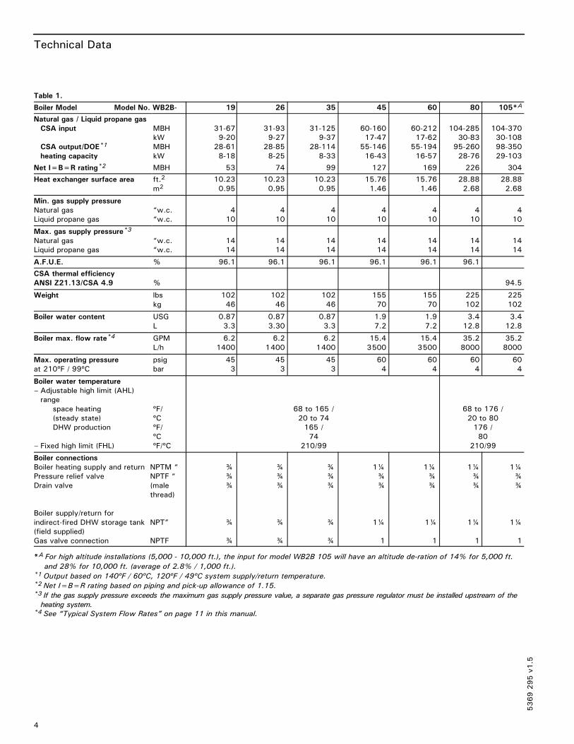
Technical Data
4
Table 1.
Boiler Model Model No. WB2B- 19 26 35 45 60 80 105*A
Natural gas / Liquid propane gas
CSA input
CSA output/DOE*1
heating capacity
MBH
kW
MBH
kW
31-67
9-20
28-61
8-18
31-93
9-27
28-85
8-25
31-125
9-37
28-114
8-33
60-160
17-47
55-146
16-43
60-212
17-62
55-194
16-57
104-285
30-83
95-260
28-76
104-370
30-108
98-350
29-103
Net I=B=R rating*2 MBH 53 74 99 127 169 226 304
Heat exchanger surface area ft.2
m210.23
0.95
10.23
0.95
10.23
0.95
15.76
1.46
15.76
1.46
28.88
2.68
28.88
2.68
Min. gas supply pressure
Natural gas
Liquid propane gas
“w.c.
“w.c.
4
10
4
10
4
10
4
10
4
10
4
10
4
10
Max. gas supply pressure*3
Natural gas
Liquid propane gas
“w.c.
“w.c.
14
14
14
14
14
14
14
14
14
14
14
14
14
14
A.F.U.E. % 96.1 96.1 96.1 96.1 96.1 96.1
CSA thermal efficiency
ANSI Z21.13/CSA 4.9 % 94.5
Weight lbs
kg
102
46
102
46
102
46
155
70
155
70
225
102
225
102
Boiler water content USG
L
0.87
3.3
0.87
3.30
0.87
3.3
1.9
7.2
1.9
7.2
3.4
12.8
3.4
12.8
Boiler max. flow rate*4 GPM
L/h
6.2
1400
6.2
1400
6.2
1400
15.4
3500
15.4
3500
35.2
8000
35.2
8000
Max. operating pressure
at 210ºF / 99ºC
psig
bar
45
3
45
3
45
3
60
4
60
4
60
4
60
4
Boiler water temperature
– Adjustable high limit (AHL)
range
space heating
(steady state)
DHW production
– Fixed high limit (FHL)
ºF/
ºC
ºF/
ºC
ºF/ºC
68 to 165 /
20 to 74
165 /
74
210/99
68 to 176 /
20 to 80
176 /
80
210/99
Boiler connections
Boiler heating supply and return NPTM “
Pressure relief valve NPTF “
Drain valve (male
thread)
Boiler supply/return for
indirect-fired DHW storage tank NPT”
(field supplied)
Gas valve connection NPTF
¾
¾
¾
¾
¾
¾
¾
¾
¾
¾
¾
¾
¾
¾
¾
1¼
¾
¾
1¼
1
1¼
¾
¾
1¼
1
1¼
¾
¾
1¼
1
1¼
¾
¾
1¼
1
*A For high altitude installations (5,000 - 10,000 ft.), the input for model WB2B 105 will have an altitude de-ration of 14% for 5,000 ft.
and 28% for 10,000 ft. (average of 2.8% / 1,000 ft.).*1 Output based on 140ºF / 60ºC, 120ºF / 49ºC system supply/return temperature.*2 Net I=B=R rating based on piping and pick-up allowance of 1.15.*3 If the gas supply pressure exceeds the maximum gas supply pressure value, a separate gas pressure regulator must be installed upstream of the
heating system.*4 See “Typical System Flow Rates” on page 11 in this manual.
5369295v1.5

Technical Data
5
Table 1 (continued)
Boiler Model Model No. WB2B- 19 26 35 45 60 80 105*A
Dimensions
Overall depth
Overall width
Overall height
Height with flue gas elbow
(accessory)
inches
mm
inches
mm
inches
mm
inches
mm
14
360
17¾
450
33½
850
44
1116
14
360
17¾
450
33½
850
44
1116
14
360
17¾
450
33½
850
44
1116
15
380
19
480
33½
850
47¼
1200
15
380
19
480
33½
850
47¼
1200
21
530
19
480
33½
850
47¼*9
1200
21
530
19
480
33½
850
47¼*9
1200
Flue gas*5
Temperature (at boiler return
temperature of 86ºF / 30ºC)
– at rated full load
– at rated partial load
Temperature (at boiler return
temperature of 140ºF / 60ºC)
ºF/ºC
ºF/ºC
ºF/ºC
113/45
95/35
154/68
113/45
95/35
158/70
113/45
95/35
158/70
95/35
91/33
149/65
104/40
95/35
158/70
95/35
91/33
149/65
104/40
95/35
158/70
Average condensate
flow rate*6
with natural gas and
TS/TR=104/86ºF / 40/30ºC USG/day
L/day
2.6-3.4
10-12
2.9-3.4
11-13
4-4.5
15-17
3.7-5
14-19
6-7.4
23-28
6.6-7.9
25-30
9.5-10.5
35-40
Condensate connection*7 hose
nozzle
∅ in 1 1 1 1 1 1 1
Boiler flue gas connection*8 ∅
in/mm 23/8 /60 23/8 /60 23/8 /60 3¼/80 3¼/80 43/8 /110 43/8 /110
Combustion air supply
connection (coaxial)*8outer
∅ in/mm 4/100 4/100 4/100 5/125 5/125 6/150 6/150
*A For high altitude installations (5,000 - 10,000 ft.), the input for model WB2B 105 will have an altitude de-ration of 14% for 5,000 ft.
and 28% for 10,000 ft. (average of 2.8% / 1,000 ft.).*5 Measured flue gas temperature with a combustion air temperature of 68°F / 20°C.*6 Based on typical boiler cycles, including partial load conditions.*7 Requires 1” / 25 mm tubing. See the Installation Instructions of the Vitodens 200-W, WB2B for details.*8 For side wall vent installations (coaxial system):
Do not exceed max. equivalent length specified in the Installation Instructions of the Vitodens 200-W, WB2B Venting System.
A maximum of 5 elbows may be installed in the vent system.
Do not attempt to common-vent Vitodens 200-W with any other appliance.
Venting material to be supplied by Viessmann only; side wall vent installation must include Viessmann protective screen!
For details refer to the Installation Instructions for the Vitodens 200-W, WB2B Venting System.*9 Add 2½” / 65 mm for coaxial vent pipe transition adaptor.
� For information regarding other Viessmann System Technology componentry, please reference documentation of respective product.
5369295v1.5

Dimensional Information
6¼” / 158 mm
55/8” /143 mm
1¾” /44 mm
141/8” /360 mm
2¾” /70 mm
2½” /65 mm
7” / 177 mm
13¾” /348 mm
87/8” / 225 mm
4” / 102 mm
4” / 102 mm
33½” /850 mm
12” /300 mm
2¾” /70 mm
17¾” /450 mm
BS BR
PRV
BD
DS
GC
DR
BF
*1 DHW Connections(Field Supplied)
EXTEXT
Floor line
78” / 1975 mmfor single boilerinstallation
Fig. 1
Fig. 2
Fig. 3
6
*1
Models WB2B 19, 26, 35
Legend
BD Boiler Drain
BR Boiler Return
BS Boiler Supply
AV Air Vent (not shown)
GC Gas Connection, ¾” NPT
PRV Pressure Relief Valve
BF Boiler Fill
PG Pressure Gage
EXT Extension Adaptors, ¾” NPT
DR Boiler heating return for domestic hot
water production ¾” (field supplied)
DS Boiler heating supply for domestic
hot water production ¾” (field
supplied)
*1 See page 38 for alternate DHW
connection.
5369295v1.5

Dimensional Information
19” / 480 mm
9½” / 240 mm
35½” /902 mm
39” /996 mm
41¾” /1061 mm
51” /1301 mm
78” / 1975 mmfor single boilerinstallation
9½” /240 mm
6½” /165 mm
9½” / 240 mm
3” / 80 mm
15¾” /400 mm
6½” /165 mm
5½” / 146 mm
4” / 100 mm
15” /380 mm
Ø 5” /125 mm
33½ “/850 mm
12” /305 mm
PRV
BD
GC
BF
PG
Floor line
BS BR
DS DR
*1 DHW Connections(Field Supplied)
Fig. 4
Fig. 5
Fig. 6
7
Models WB2B 45, 60
Legend
BD Boiler Drain
BR Boiler Return
BS Boiler Supply
AV Air Vent (not shown)
GC Gas Connection, 1” NPT
PRV Pressure Relief Valve
BF Boiler Fill
PG Pressure Gage
DR Boiler heating return for domestic hot
water production 1¼” NPT (field supplied)
DS Boiler heating supply for domestic hot
water production 1¼” NPT (field supplied)
*1 See page 38 for alternate DHW
connection.
5369295v1.5

Dimensional Information
19” /480mm
9½” /240mm
4¼” /108mm
33½”/
850mm
43”/
1090mm
3” / 80mm
9½” / 240mm
15¾” /400mm
6½” /165mm
9½” /240mm
9½” /236mm
4” / 102mm
21” /530mm
15¾” /400mm
Floor linePRV
BD
GC
BF
PG
78” / 1975 mmfor single boilerinstallation
BS BR
DS
*1 DHW Connections(Field Supplied)
DR
Fig. 7
Fig. 8
11 5/8“ / 295mmfor WB2B 80-105using the coaxialvent system
Fig. 9
8
Models WB2B 80, 105
Legend
BD Boiler Drain
BR Boiler Return
BS Boiler Supply
GC Gas Connection, 1” NPT
PRV Pressure Relief Valve
BF Boiler Fill
PG Pressure Gage
DR Boiler heating return for domestic hot water production 1¼”
DS Boiler heating supply for domestic hot water production 1¼”
*1 See page 38 for alternate DHW connection.
5369295v1.5

Minimum Clearances
9
Recommended Minimum Service Clearances
Minimum Clearances to Combustibles
Top Front Rear Left Right Vent pipe*1
0 0 AL, CL 0 0 0 0
AL= Alcove
CL= Closet*1Refer to the Installation Instructions of the Vitodens 200-W, WB2B Venting System for details.
Please note:
The Vitodens boiler has passed the zero inches vent clearance to combustibles testing requirements dictated by the Harmonized Standard
ANSI Z21.13. CSA 4.9.2000 and therefore is listed for zero clearance to combustibles when vented with a single wall special venting
system (AL-29-4C material). The zero inches vent clearance to combustibles for the Vitodens boiler supercedes the clearance to
combustibles listing that appears on the special venting system label.
5369295v1.5
Front
12” / 305 mm
Top12”/305 mm
0”/mm
Side
0”/mm
Back
Side
28” / 700 mm
Fig. 10
Waterside Flow
10
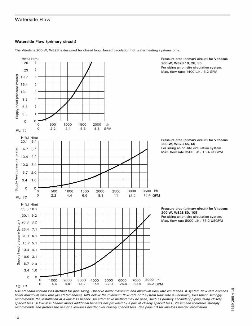
Waterside Flow (primary circuit)
The Vitodens 200-W, WB2B is designed for closed loop, forced circulation hot water heating systems only.
Pressure drop (primary circuit) for Vitodens
200-W, WB2B 19, 26, 35
For sizing an on-site circulation system.
Max. flow rate: 1400 L/h / 6.2 GPM
Pressure drop (primary circuit) for Vitodens
200-W, WB2B 45, 60
For sizing an on-site circulation system.
Max. flow rate 3500 L/h / 15.4 USGPM
Pressure drop (primary circuit) for Vitodens
200-W, WB2B 80, 105
For sizing an on-site circulation system.
Max. flow rate 8000 L/h / 35.2 USGPM
Use standard friction loss method for pipe sizing. Observe boiler maximum and minimum flow rate limitations. If system flow rate exceeds
boiler maximum flow rate (as stated above), falls below the minimum flow rate or if system flow rate is unknown, Viessmann strongly
recommends the installation of a low-loss header. An alternative method may be used, such as primary secondary piping using closely
spaced tees. A low-loss header offers additional benefits not provided by a pair of closely spaced tees. Viessmann therefore strongly
recommends and prefers the use of a low-loss header over closely spaced tees. See page 13 for low-loss header information.
5369295v1.5
0 500 1000 15000
1
2
3
4
5
6
0
3.3
6.6
9.8
13.1
16.4
19.7
2000 l/h
7
8
23
26
Supplyheadpressure(water)
0 2.2 4.4 6.6 8.8 GPM
H(ft.) H(m)
Fig. 11
H(ft.) H(m)20.1 6.1
16.7 5.1
13.4 4.1
10.0 3.1
6.7 2.0
3.4 1.0
0 0
0
0 500 1000 1500 2000 2500 3000 3500 l/h
2.2 4.4 6.6 8.8 11 13.2 15.4 GPM
Supplyheadpressure(water)
Fig. 12
H(ft.) H(m)
33.5 10.2
30.1 9.2
8.226.8
7.123.4
6.120.1
5.116.7
4.113.4
3.110.0
2.06.7
1.03.4
000
01000 2000 3000 4000 5000 6000 7000 8000 l/h
4.4 8.8 13.2 17.6 22.0 26.4 30.8 35.2 GPM
Supplyheadpressure(water)
Fig. 13
System Flow Rates
11
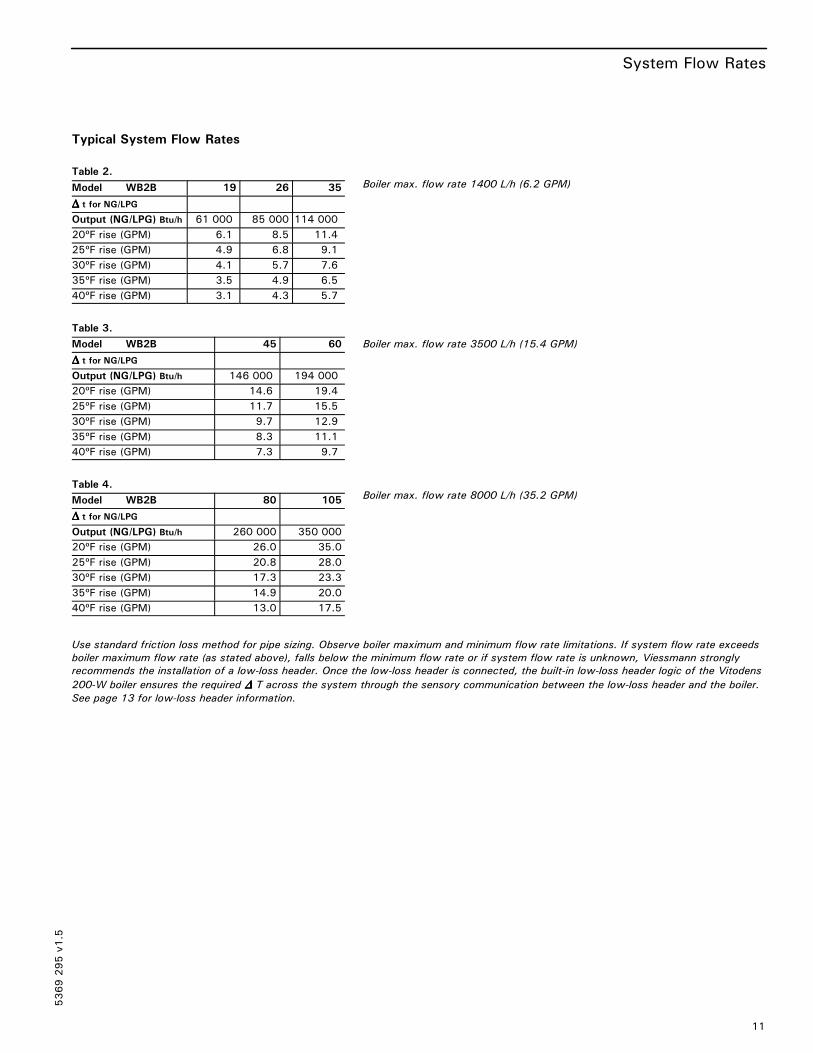
Typical System Flow Rates
Table 2.
Model WB2B 19 26 35
∆∆∆∆ t for NG/LPG
Output (NG/LPG) Btu/h 61 000 85 000 114 000
20ºF rise (GPM) 6.1 8.5 11.4
25ºF rise (GPM) 4.9 6.8 9.1
30ºF rise (GPM) 4.1 5.7 7.6
35ºF rise (GPM) 3.5 4.9 6.5
40ºF rise (GPM) 3.1 4.3 5.7
Table 3.
Model WB2B 45 60
∆∆∆∆ t for NG/LPG
Output (NG/LPG) Btu/h 146 000 194 000
20ºF rise (GPM) 14.6 19.4
25ºF rise (GPM) 11.7 15.5
30ºF rise (GPM) 9.7 12.9
35ºF rise (GPM) 8.3 11.1
40ºF rise (GPM) 7.3 9.7
Table 4.
Model WB2B 80 105
∆∆∆∆ t for NG/LPG
Output (NG/LPG) Btu/h 260 000 350 000
20ºF rise (GPM) 26.0 35.0
25ºF rise (GPM) 20.8 28.0
30ºF rise (GPM) 17.3 23.3
35ºF rise (GPM) 14.9 20.0
40ºF rise (GPM) 13.0 17.5
Use standard friction loss method for pipe sizing. Observe boiler maximum and minimum flow rate limitations. If system flow rate exceeds
boiler maximum flow rate (as stated above), falls below the minimum flow rate or if system flow rate is unknown, Viessmann strongly
recommends the installation of a low-loss header. Once the low-loss header is connected, the built-in low-loss header logic of the Vitodens
200-W boiler ensures the required ∆∆∆∆ T across the system through the sensory communication between the low-loss header and the boiler.
See page 13 for low-loss header information.
5369295v1.5
Boiler max. flow rate 1400 L/h (6.2 GPM)
Boiler max. flow rate 3500 L/h (15.4 GPM)
Boiler max. flow rate 8000 L/h (35.2 GPM)

Pump Information
12
Heating Circuit / Boiler Pumps
Viessmann offers a variety of Grundfos heating circuit / boiler pumps which meet typical Vitodens system installation requirements (see
“Heating circuit pump (field supplied)“ or “Boiler pump (field supplied)” in the Installation Examples starting on page 29). See tables below
for recommended pumps. Refer to the graphs on page 10 for the proper waterside boiler friction loss calculations.
Pump selection must be based on accurate
system flow and pressure drop calculations
(incl. DHW sizing).
The following pumps have been selected based on boiler heat exchanger head loss and boiler piping to a low-loss header. Before
using the following pumps for a DHW tank application, find out the proper pressure drop through the tank, the required
temperature difference through the coil and system piping head loss of the domestic hot water.
Table 5.
Model WB2B 19 26 35
Flow rate
20 ºF ∆∆∆∆ t 6.1 8.5 11.4
25 ºF ∆∆∆∆ t 4.9 6.8 9.1
30 ºF ∆∆∆∆ t 4.1 5.7 7.6
35 ºF ∆∆∆∆ t 3.5 4.9 6.5
40 ºF ∆∆∆∆ t 3.1 4.3 5.7
Flow limitation L/h / GPM 1400 / 6.2
Recommended boiler pumps Grundfos 15-58 (3-speed)
Taco 00R
Wilo Star S 21 FX
Table 6.
Model WB2B 45
Flow rate Boiler pressure
drop (ft.)
Recommended pump option 1
Grundfos
Recommended pump option 2
Grundfos
20 ºF ∆∆∆∆ t 14.6 15.8 UPS 26-99FC, 115V, Speed3
25 ºF ∆∆∆∆ t 11.7 10.0 UPS 26-99FC, 115V, Speed2 UP 26-64F, 115V
30 ºF ∆∆∆∆ t 9.7 7.5 UPS 26-99FC, 115V, Speed2
35 ºF ∆∆∆∆ t 8.3 5.8 UPS 26-99FC, 115V, Speed1
40 ºF ∆∆∆∆ t 7.3 4.2 UPS 26-99FC, 115V, Speed1
Flow limitation L/h / GPM 3500 / 15.4
Table 7.
Model WB2B 60
Flow rate Boiler pressure
drop (ft.)
Recommended pump option 1
Grundfos
Recommended pump option 2
Grundfos
20 ºF ∆∆∆∆ t 19.4 Not Recommended Not Recommended
25 ºF ∆∆∆∆ t 15.5 16.7 UPS 26-99FC, 115V, Speed3
30 ºF ∆∆∆∆ t 12.9 12.6 UPS 26-99FC, 115V, Speed3 UP 26-64F, 115V
35 ºF ∆∆∆∆ t 11.1 9.2 UPS 26-99FC, 115V, Speed2 UP 26-64F, 115V
40 ºF ∆∆∆∆ t 9.7 7.5 UPS 26-99FC, 115V, Speed2
Flow limitation L/h / GPM 3500 / 15.4
5369295v1.5
IMPORTANT

Pump and Low-Loss Header Information
13
Heating Circuit / Boiler Pumps (continued)
Table 8.
Model WB2B 80
Flow rate Boiler pressure
drop (ft.)
Recommended pump
Grundfos
20 ºF ∆∆∆∆ t 26.0 16.7 UPS 32-160/2, 115V, Speed1 / UPS 26-150F, 115V, Speed 3
25 ºF ∆∆∆∆ t 20.8 9.2 UPS 26-99FC, 115V, Speed3
30 ºF ∆∆∆∆ t 17.3 6.5 UPS 26-99FC, 115V, Speed2
35 ºF ∆∆∆∆ t 14.9 4.8 UPS 26-99FC, 115V, Speed2
40 ºF ∆∆∆∆ t 13.0 3.4 UPS 26-99FC, 115V, Speed2
Flow limitation L/h / GPM 8000 / 35.2
Table 9.
Model WB2B 105
Flow rate Boiler pressure
drop (ft.)
Recommended pump
Grundfos
20 ºF ∆∆∆∆ t 35.0 30.0 UPS 32-160/2, 115V, Speed3
25 ºF ∆∆∆∆ t 28.0 20.0 UPS 32-160/2, 115V, Speed2 / UPS 26-150F, 115V, Speed 3
30 ºF ∆∆∆∆ t 23.3 12.5 UPS 32-160/2, 115V, Speed1
35 ºF ∆∆∆∆ t 20.0 9.0 UPS 26-99FC, 115V, Speed3
40 ºF ∆∆∆∆ t 17.5 6.4 UPS 26-99FC, 115V, Speed2
Flow limitation L/h / GPM 8000 / 35.2
Table 10. Sizing of Low-Loss Header in a Residential Single-Boiler Application
BoilerModel
No. ofBoilers
BoilerMax.
Flow Rate
Typical System Flow Rates ViessmannTemp. SensorRequired
System ∆∆∆∆ t *1 2011.0
2513.9
3016.8
3516.1
4013.4
°F°C
WB2B 19 1 6.11385
System Flow Rate
LLH RequiredLLH Model
6.11385Yes
80/60
4.91108
Optional80/60
4.1924
Optional80/60
3.5792
Optional80/60
3.1693
Optional80/60
GPML/h
Yes
WB2B 26 1 6.11385
System Flow Rate
LLH RequiredLLH Model
8.51931Yes
80/60
6.81544Yes
80/60
5.71287
Optional80/60
4.91103
Optional80/60
4.3965
Optional80/60
GPML/h
Yes
WB2B 35 1 6.11385
System Flow Rate
LLH RequiredLLH Model
11.42589Yes
80/60
9.12071Yes
80/60
7.61726Yes
80/60
6.51480Yes
80/60
5.71295
Optional80/60
GPML/h
Yes
WB2B 45 1 15.43498
System Flow Rate
LLH RequiredLLH Model
14.63316Yes
80/60
11.72653
Optional80/60
9.72211
Optional80/60
8.31895
Optional80/60
7.31658
Optional80/60
GPML/h
Yes
WB2B 60 1 15.43498
System Flow Rate
LLH RequiredLLH Model
19.44406Yes
80/60
15.53525Yes
80/60
12.92937
Optional80/60
11.12518
Optional80/60
9.72203
Optional80/60
GPML/h
Yes
WB2B 80 1 357949
System Flow Rate
LLH RequiredLLH Model
26.05905Yes
120/80
20.84724Yes
120/80
17.33937
Optional120/80
14.93374
Optional120/80
13.02953
Optional120/80
GPML/h
Yes
WB2B 105 1 357949
System Flow Rate
LLH RequiredLLH Model
35.27949Yes
120/80
28.06359Yes
120/80
23.35300Yes
120/80
20.04542
Optional120/80
17.53975
Optional120/80
GPML/h
Yes
*1 For system ∆t < 20°F use low-loss header sizes for ∆t 20°F.
5369295v1.5
Low-Loss Header Information
14
Low-Loss Header Application (continued)
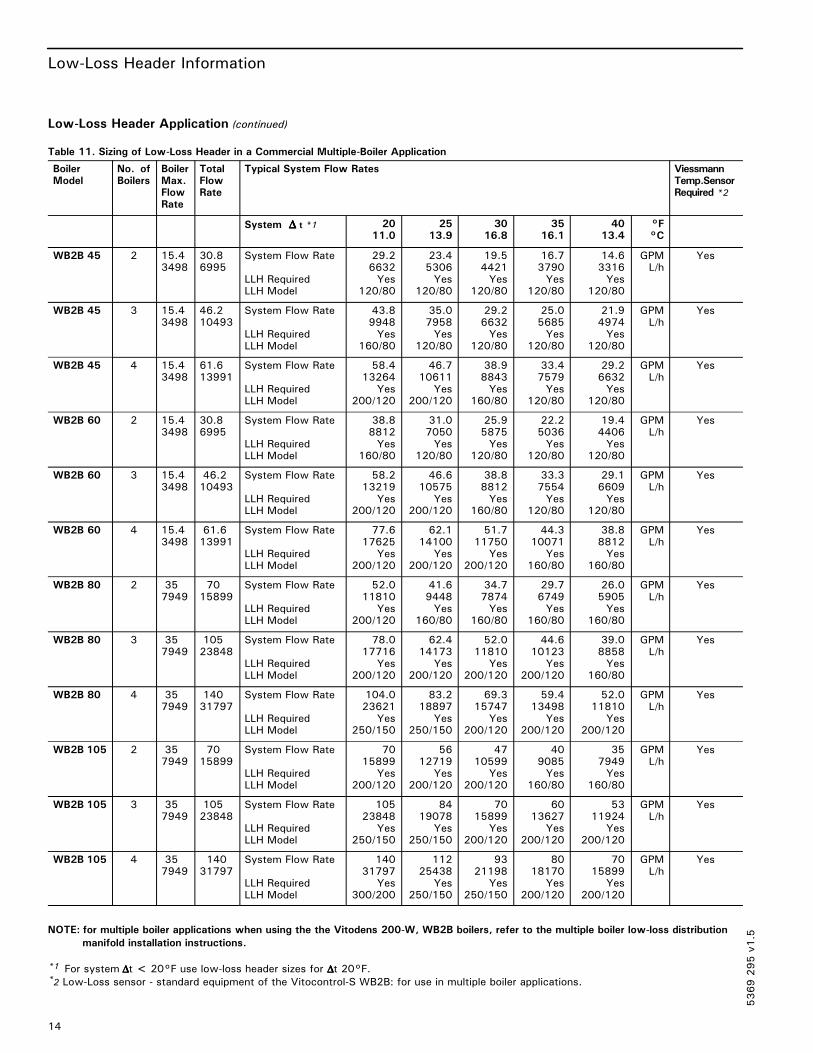
Table 11. Sizing of Low-Loss Header in a Commercial Multiple-Boiler Application
BoilerModel
No. ofBoilers
BoilerMax.FlowRate
TotalFlowRate
Typical System Flow Rates ViessmannTemp.SensorRequired *2
System ∆∆∆∆ t *1 2011.0
2513.9
3016.8
3516.1
4013.4
°F°C
WB2B 45 2 15.43498
30.86995
System Flow Rate
LLH RequiredLLH Model
29.26632Yes
120/80
23.45306Yes
120/80
19.54421Yes
120/80
16.73790Yes
120/80
14.63316Yes
120/80
GPML/h
Yes
WB2B 45 3 15.43498
46.210493
System Flow Rate
LLH RequiredLLH Model
43.89948Yes
160/80
35.07958Yes
120/80
29.26632Yes
120/80
25.05685Yes
120/80
21.94974Yes
120/80
GPML/h
Yes
WB2B 45 4 15.43498
61.613991
System Flow Rate
LLH RequiredLLH Model
58.413264
Yes200/120
46.710611
Yes200/120
38.98843Yes
160/80
33.47579Yes
120/80
29.26632Yes
120/80
GPML/h
Yes
WB2B 60 2 15.43498
30.86995
System Flow Rate
LLH RequiredLLH Model
38.88812Yes
160/80
31.07050Yes
120/80
25.95875Yes
120/80
22.25036Yes
120/80
19.44406Yes
120/80
GPML/h
Yes
WB2B 60 3 15.43498
46.210493
System Flow Rate
LLH RequiredLLH Model
58.213219
Yes200/120
46.610575
Yes200/120
38.88812Yes
160/80
33.37554Yes
120/80
29.16609Yes
120/80
GPML/h
Yes
WB2B 60 4 15.43498
61.613991
System Flow Rate
LLH RequiredLLH Model
77.617625
Yes200/120
62.114100
Yes200/120
51.711750
Yes200/120
44.310071
Yes160/80
38.88812Yes
160/80
GPML/h
Yes
WB2B 80 2 357949
7015899
System Flow Rate
LLH RequiredLLH Model
52.011810
Yes200/120
41.69448Yes
160/80
34.77874Yes
160/80
29.76749Yes
160/80
26.05905Yes
160/80
GPML/h
Yes
WB2B 80 3 357949
10523848
System Flow Rate
LLH RequiredLLH Model
78.017716
Yes200/120
62.414173
Yes200/120
52.011810
Yes200/120
44.610123
Yes200/120
39.08858Yes
160/80
GPML/h
Yes
WB2B 80 4 357949
14031797
System Flow Rate
LLH RequiredLLH Model
104.023621
Yes250/150
83.218897
Yes250/150
69.315747
Yes200/120
59.413498
Yes200/120
52.011810
Yes200/120
GPML/h
Yes
WB2B 105 2 357949
7015899
System Flow Rate
LLH RequiredLLH Model
7015899
Yes200/120
5612719
Yes200/120
4710599
Yes200/120
409085Yes
160/80
357949Yes
160/80
GPML/h
Yes
WB2B 105 3 357949
10523848
System Flow Rate
LLH RequiredLLH Model
10523848
Yes250/150
8419078
Yes250/150
7015899
Yes200/120
6013627
Yes200/120
5311924
Yes200/120
GPML/h
Yes
WB2B 105 4 357949
14031797
System Flow Rate
LLH RequiredLLH Model
14031797
Yes300/200
11225438
Yes250/150
9321198
Yes250/150
8018170
Yes200/120
7015899
Yes200/120
GPML/h
Yes
NOTE: for multiple boiler applications when using the the Vitodens 200-W, WB2B boilers, refer to the multiple boiler low-loss distribution
manifold installation instructions.
*1 For system ∆∆∆∆t < 20°F use low-loss header sizes for ∆∆∆∆t 20°F.*2 Low-Loss sensor - standard equipment of the Vitocontrol-S WB2B: for use in multiple boiler applications.
5369295v1.5
DHW Production
15
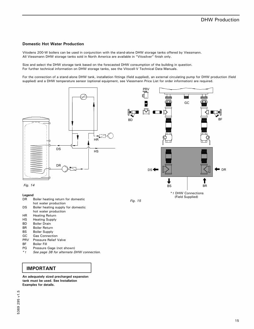
Domestic Hot Water Production
Vitodens 200-W boilers can be used in conjunction with the stand-alone DHW storage tanks offered by Viessmann.
All Viessmann DHW storage tanks sold in North America are available in “Vitosilver” finish only.
Size and select the DHW storage tank based on the forecasted DHW consumption of the building in question.
For further technical information on DHW storage tanks, see the Vitocell-V Technical Data Manuals.
For the connection of a stand-alone DHW tank, installation fittings (field supplied), an external circulating pump for DHW production (field
supplied) and a DHW temperature sensor (optional equipment, see Viessmann Price List for order information) are required.
Legend
DR Boiler heating return for domestic
hot water production
DS Boiler heating supply for domestic
hot water production
HR Heating Return
HS Heating Supply
BD Boiler Drain
BR Boiler Return
BS Boiler Supply
GC Gas Connection
PRV Pressure Relief Valve
BF Boiler Fill
PG Pressure Gage (not shown)
*1 See page 38 for alternate DHW connection.
An adequately sized precharged expansion
tank must be used. See Installation
Examples for details.
5369295v1.5
DR
HR
HSDS
Fig. 14
PRV
BD
GC
BF
BS BR
DS
*1 DHW Connections(Field Supplied)
DR
Fig. 15
IMPORTANT

DHW Recirculation
16
Domestic Hot Water Recirculation
DHW recirculation lines increase the level of comfort and convenience of the domestic hot water supply and reduce water consumption.
These advantages directly derive from the immediate availability of domestic hot water at all draw points.
Poor insulation of the DHW recirculation line, however, can result in considerable heat loss. Viessmann therefore recommends that
effective insulation be provided and used for DHW recirculation lines of 23 ft. / 7 m in length or longer.
Legend
DCW Domestic Cold Water
DHW Domestic Hot Water
TPV Temperature and Pressure Relief
Valve (on tank - not shown)
R DHW Recirculation Line
RP DHW Recirculation Pump
5369295v1.5
Vitocell-V stand-alone DHW storage tank
DCWDCW
DHW
RRP
Fig. 16
Wall Mounting
17
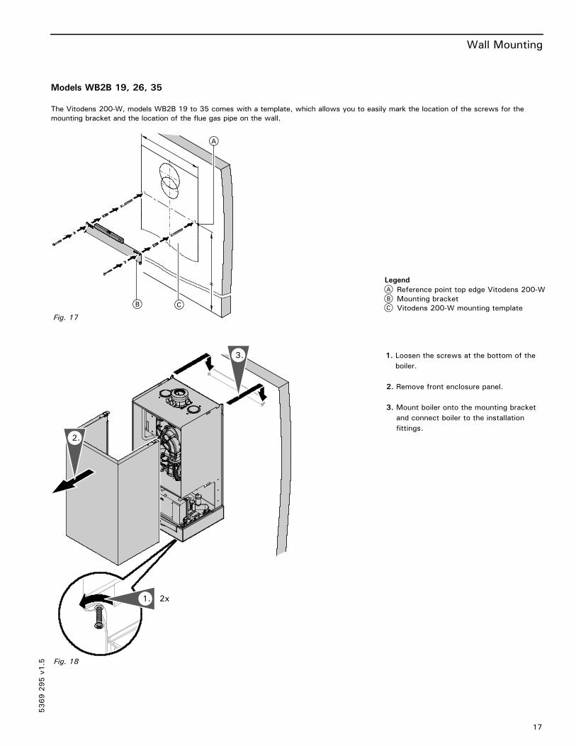
Models WB2B 19, 26, 35
The Vitodens 200-W, models WB2B 19 to 35 comes with a template, which allows you to easily mark the location of the screws for the
mounting bracket and the location of the flue gas pipe on the wall.
1. Loosen the screws at the bottom of the
boiler.
2. Remove front enclosure panel.
3. Mount boiler onto the mounting bracket
and connect boiler to the installation
fittings.
5369295v1.5
A
CB
Fig. 17
A Reference point top edge Vitodens 200-W
B Mounting bracket
C Vitodens 200-W mounting template
Legend
3.
2.
2x1.
Fig. 18
Wall Mounting
18
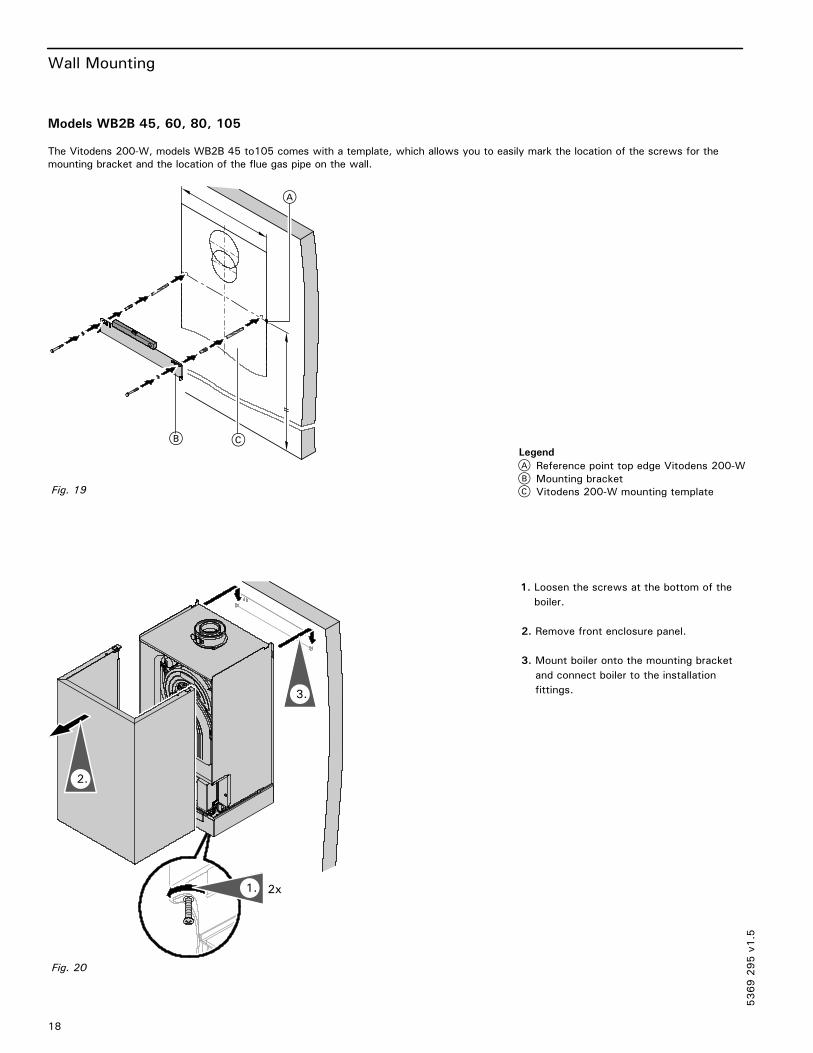
Models WB2B 45, 60, 80, 105
The Vitodens 200-W, models WB2B 45 to105 comes with a template, which allows you to easily mark the location of the screws for the
mounting bracket and the location of the flue gas pipe on the wall.
1. Loosen the screws at the bottom of the
boiler.
2. Remove front enclosure panel.
3. Mount boiler onto the mounting bracket
and connect boiler to the installation
fittings.
5369295v1.5
A
CB
A Reference point top edge Vitodens 200-W
B Mounting bracket
C Vitodens 200-W mounting templateFig. 19
Legend
2x1.
3.
2.
Fig. 20

Condensate Connection/Neutralization Unit
19
Condensate Connection
Install the condensate drain pipe with a suitable gradient.
Discharge condensate from the boiler into the drainage system, either directly or (if required) via a neutralization unit (accessory).
Pipe ventilation must take place between
the siphon trap and the neutralization unit (if
applicable).
Condensate Connection for
Vitodens 200-W, models WB2B 19, 26, 35
Condensate Connection for
Vitodens 200-W, models WB2B 45, 60
Condensate Connection for
Vitodens 200-W, models WB2B 80, 105
Condensate Drainage and Neutralization
The condensate formed both in the
condensing boiler and in the flue gas pipe
must be discharged into the public sewage
system in accordance with all applicable
local regulations. The condensate produced
by a gas-fired heating system has a pH
value between 3 and 4.
Some local codes may require the use of a
separate neutralization unit to treat the
aggressive and corrosive nature of the
condensate. With a neutralization unit
installed, all condensate from the boiler and
the flue gas pipe enters into the
neutralization unit where it is treated and
released into the public sewage system with
a safe pH value of above 6.5.
The use of neutralization granulate
(performing the neutralizing process) is
dependent on the operation of the heating
system. To determine the required refill
amount, check granulate level several times
during the first year of operation. In some
cases one granulate fill may last an entire
year.
Contact Viessmann to order a neutralization
unit for the Vitodens 200-W boiler.
See Viessmann Price List for order
information.
The condensate discharge outlet to the
drainage system connection must be clearly
visible. It must be installed with a suitable
gradient and provided with a stench trap.
If the condensate outlet of the Vitodens
200-W boiler is lower than the drain, a
condensate pump must be used.
Only corrosion-resistant materials must be
used for condensate drainage purposes (e.g.
braided hose). Do not use galvanized
materials or materials containing copper for
piping, couplings etc.
The condensate drain must have a trap to
prevent flue gas leakage.
Please note that other requirements might
apply depending on local regulations and/or
project-specific details.
It is advisable to contact your local
waterworks office (authority responsible for
waste water regulations) well before
commencing with the installation of the
neutralization unit in order to establish
details of local regulations that apply.
The following table shows the concentration
of (effluent) substances (e.g. heavy metals)
contained in the waste water from the
Vitodens 200-W condensing boiler.
Table 12.
Condensate
(effluent)
substances
Values measured
in mg/L(effluent)
substances Vitodens 200-W
Lead
Cadmium
Chromium
Copper
Nickel
Zinc
Tin
< 0.01
< 0.005
< 0.01
< 0.01
< 0.01
< 0.05
< 0.05
5369295v1.5
IMPORTANT
Fig. 21
Fig. 22
Fig. 23

Venting Options / Electrical Connection / Boiler Control
Fig. 26
4
+
?
OK
0
1
2
3
0
+RESET
s
?F
A
140Mo
Boiler temp.
20
Venting Options
For an overview of venting options refer to the appendix starting on page NO TAG. For detailed information refer to the Installation
Instructions for the Vitodens 200-W, WB2B Venting System.
Electrical Connection
For an overview of the required wiring refer to pages 39 (for WB2B 19 to 60) and 40 (for WB2B 80 and 105).
Power Supply
The Vitodens 200-W is shipped with a
Power / Pump Module. The module requires
a 120 VAC power supply from a wall
receptacle. The module contains a 120/230
VAC step-up transformer to power the
Vitodens 200-W with 230 VAC. Refer to
the Installation Instructions shipped with the
module for wiring details, or reference the
“Overview of Electrical Connections” on
pages 39 and 40 of this manual.
Power Supply Connection of Accessories
The power supply connection of accessories
can be made directly at the boiler control.
The connection is activated and deactivated
with the system on/off switch.
The mixing valve accessory kit and the
Vitosolic control (if used) will require a
separate 120 VAC power supply from the
wall receptacle.
Wire cabling required for:
� outdoor temperature sensor
� Vitotronic 200-H, HK1M mixing valve
control
� accessory kit for heating circuit with
mixing valve
� Vitotrol 200 remote control
� Vitotrol 300 remote control
� remote switching of operating mode
� remote disable
� alarm output
On-Board Vitotronic 200, HO1 Outdoor Reset Control
The on-board Vitodens menu-driven Vitotronic 200, HO1 control provides the following:5369295v1.5
Vent Connection, models WB2B 19, 26, 35
(with optional air intake openings on sides)
Vent Connection, models WB2B 45, 60, 80,105Fig. 24 Fig. 25

Boiler Control
21
Design and Functions
Modular Structure
The control unit contains:System on/off switch, override/emissiontest switch, fixed high limit, adjustable highlimit, digital display, micro-computer,adjustment options for switching times, fortemperatures during normal and reducedoperation, domestic hot water temperature,adjustment options for heating curves,temperature scanning options, built-indiagnostic system and fuses, reset button,analogue pressure display.
Programming Unit
� Illuminated display with plain text support� Adjustment and display of temperatures
and codes
� All settings, main codings and faultmessages shown in plain text
� Holiday program� Party button for switching to ”normaloperation” whenever required
� Energy savings button for lowering thedesired room temperature by approx.3.6°F / 2°C in normal operation
� Rotary selector for the temperature instandard mode
� Keys:
- Program selection
- Holiday program
- Party and economy mode
- Temperature for reduced mode
- DHW temperature
- Emissions test function
- Time/date
Boiler-Specific Functions
The control unit adjusts the boiler watertemperature (= supply temperature of adirect-connected heating circuit and/or aheating circuit with mixing valve in conjunctionwith the accessory kit for a heating circuitwith mixing valve) automatically and on acontinuous basis to individual outdoortemperatures. The control has a DHWtemperature controller with DHW priorityswitching (heating circuit pump off).
Functions
� Outdoor reset control of boiler water
and/or supply temperature
� Electronic maximum temperature limit
� Demand-dependent heating circuit pump
and burner OFF control
� Anti-seizing pump protection
�Maintenance display
� Heating system frost protection
� Integral diagnostic system
� DHW temperature control with priority
control
�
� Auxiliary function for DHW heating
(short-term heating to a higher
temperature, gas fired central heating
boiler)
� Adjusting switching times for the DHW
recirculation pump
� 0-10 V external signal input
� Boiler pump contol output
� Alarm output
� Heating circuit pump control output
� DHW pump control output
� DHW recirculation pump control output
Control Characteristics
PI characteristics with modulating output.
Time Switch
Digital time switch.
� Individual and 7-day program
� Automatic daylight savings time
changeover
� Automatic function for DHW heating and
DHW recirculation pump
� Time, day and standard switching times
for space heating, DHW heating and the
DHW circulation pump are factory-set
� Switching times are individually
programmable, i.e. up to four switching
periods per day
Shortest switching interval: 10 minutes
Power backup: 14 days.
Setting the Heating Programs
The heating system frost protection (seefrost protection function) applies to allheating programs.You can select the following heatingprograms wiyh the program keys:� Heating and DHW
� DHW only
� Standby mode
External heating program changeover.
Summer Operation
Heating program “w“The burner is only activated upon a call fordomestic hot water from the DHW storagetank (controlled by DHW tank temperaturesensor).Frost protection
� The frost protection function will be
started when the ouside temperature
drops below approx. 34°F / +1°C.
With the frost protection function, the
heating circuit pump will be switched ON
and the boiler water is maintained at a
lower temperature of approx. 68°F /
20° C.
The DHW tank will be heated to approx.
68°F / +20°C.
� The frost protection function will be
stopped when the outside temperature
rises above approx. 37°F / +3°C (default
settings).
Technical Data
Rated supply voltage: 120 VACRated frequency: 60 HzRated current: 12 AMax. ambienttemperature� at operation: 32 to 104ºF
0 to 40ºCInstallation in livingspaces or boilerrooms (standardambientconditions)
�when storing ortransporting: –4 to +158ºF
–20 to +70ºCMax. operating temp.setting (space heating):Models WB2B 19-60 165ºF / 74ºCModels WB2B 80-105 176ºF / 80ºCDHW production:Models WB2B 19-60 165ºF / 74ºCModels WB2B 80-105 176ºF / 80ºCSetting fixedhigh limit: 210ºF / 99ºC
(not adjustable)Adjustment rangeof DHW tank set-pointtemperature: 50 to 154ºF
10 to 68ºCAdjustment rangeheating curves� Heating curve� slope 0.2 to 3.5� Heating curve� shift: –12 to +33ºC
–13 to 40 K
5369295v1.5

Boiler Control
22
Heating Curve Adjustment (slope and shift)
The control unit regulates the boiler water
temperature (= supply temperature of
heating circuit without mixing valve) and the
supply temperature of the heating circuit
with mixing valve (in conjunction with the
accessory kit for a heating circuit with
mixing valve) according to the outdoor
temperature. The boiler water temperature
is automatically raised by 0 to 72 F / 0 to
40 K higher than the currently required set
supply termperature (in the factory default
setting the differential temperature is
14.4 F / 8 K). See Start-up/Service
Instructions for coding address “9F” in
coding level 2.
The supply temperature that is required to
achieve a given room temperature depends
on the heating system and the thermal
insulation of the building that is being
heated.
The adjustment of the two heating curves is
used to match the boiler water temperature
and the supply temperature to these
conditions. The boiler water temperature is
limited upwards by the fixed high limit and
the temperature set for the electronic high
limit.
The supply temperature cannot rise above
the boiler water temperature.
Legend
Low temperature heating system, e.g.
radiant floor heating
Medium temperature heating system,
e.g. cast iron radiation, staple-up
radiant floor heating
High temperature heating system,
e.g. fintube radiation, fan coils
Boiler Temperature Sensor
The boiler temperature sensor is connectedat the control unit for weather-responsiveoperation and is built into the boiler.Max. ambient temperature� at operation: 32 to 266ºF
0 to 130ºC�when storing ortransporting: – 4 to+158ºF
–20 to +70ºC
DHW Tank Temperature Sensor
Part No. 7179 114
Supplied with:� Cable length approx. 13 ft. / 3.75 m,
ready to plug in
� All pipe connections are field supplied.
Specification
Max. ambient temperature� at operation: 32 to 194ºF
0 to 90ºC
� when storing or transporting:
– 4 to+158ºF
–20 to+ 70ºC
Outdoor Temperature Sensor
Sensor location:� North or northwest wall of building� 6.6 to 8.2 ft. / 2 to 2.5 m above groundor in case of a multi-storey buildingapprox. halfway up the second floor
Electrical connection:� 2-wire cable, max. cable length 115 ft. /35 m with a wire size of min. AWG 16copper
� Cable to the outdoor sensor must not belaid near line voltage wiring(120/240 V)
Max. ambient temperature atoperation, when storingor transporting: –40 to+158ºF
–40 to +70ºC
5369295v1.5
0,2
2,4
2,62,83,0
3,2
3,4
90
80
70
60
50
40
30
0 -5 -10 -15 -20510
2,0
2,2
0,4
0,6
0,8
1,0
1,2
1,4
-30-25
1,8
1,6
Outdoor temperature
Boilerwateror
flowtemperature
Room -set-pointtemperature
194
176
158
140
122
104
86
ºF / ºC
ºCºF50 41 32 23 14 5 -4 -13 -22
9535 86
30 7725 68
20 6015 50
10 415
ºFºC
Fig. 27
A
C
B
Fig. 28 (dimensions in mm)

Control Accessories
23
Vitotronic Control Accessories
Mixing Valve Actuator Accessory Kit,
Part No. 7133 392 (old version)
Rated voltage: 120 VAC
Rated frequency: 60 Hz
Rated current: 4 (2) A
Power consumption: 4 W
Max. ambient temperature
� at operation: 32 to 104ºF
0 to 40ºC
�when storing
� or transporting: –4 to +149ºF
–20 to +65ºC
Relay output for
heating circuit pump: 4(2) A, 120 VAC
Actuator torque: 3 Nm
Time of 90 º�: 2 minutes
Supply Temperature Sensor
(strap-on sensor, included with mixing
valve actuator accessory kit),
Part No. 7133 895 (old version)
�when storing or transporting:
–20 to+70ºC
Installed with a strapping band.
Cable length 19.7 ft. / 6 m, ready to plug
in.Max. ambient temperature
� at operation: 32 to 212ºF
0 to 100ºC
�when storing or transporting:
–4 to+149ºF (–20 to+70ºC)
Mixing Valve Actuator Accessory Kit,
Part No. 7837 524 (new version)
The mixing valve actuator is mounted directly
on the Viessmann ¾ to 2½“ mixing valve.
The mixing valve actuator is a motor-driven
control unit. The rotational direction is
reversible.
The mixing valve actuator comes with a
plug-in connector for a heating circuit pump,
supply temperature sensor (strap-on sensor
with 7 ft. / 2.1 m connecting cable), power
supply connecting cable (9 ft. / 2.7 m) and a
connecting cable (9 ft. / 2.7 m) for the
KM-BUS Expansion Module.
Rated voltage: 120 VAC
Rated frequency: 60 Hz
Rated current: 4 A
Power consumption: 5W max. ambient
temperature
- at operation: 32ºF to 104ºF (0ºC to 40ºC)
application in living areas and installation
sites (normal ambient conditions)
-storage & shipping: -4ºF to 149ºF (-20ºC
to 65ºC)
Max. relay outputs at 120 VAC for:
- Heating circuit pump 1.0 A
- Mixing valve 0.2 A
Supply Temperature Sensor
Part No. 7183 288 (new version)
LON Communication Module
Part No. 7179 113
Electronic PCB for data exchange with the
Vitotronic 200-H, Vitocom 200 and for
connecting to a higher level building
management system.
LON Connecting Cable
(for data exchange between control units)
Cable length 23 ft / 7m, fully wired
LON Terminal End Resistor
Part No. 7143 497
To terminate the LON BUS at the first and
the last control unit.
KM BUS Expansion Module
Part No. 7133 393
To connect 2 to 9 devices (mixing valve
actuator, Vitotrol, input module, etc.) to the
single KM BUS connection of the boiler.
Specification
Lead lenght 10 ft / 3.0 m,
fully wired
Permissable ambient temperature
- during operation 32 to 104°F
0 to 40°C
- during storage and
transport - 4 to+149°F
-20 to +65°C
Immersion temperature sensor
Part No. 7173 488
To capture the low loss temperature
Specification
Lead length 12 ft / 3.75 m,
fully wired
Permissable ambient temperature
- during operation 32 to 194°F
0 to 90°C
- during storage and
transport - 4 to+158°F
-20 to +70°C
5369295v1.5
Fig. 29 (dimensions in mm)
Fig. 30 (dimensions in mm)
Fig. 31 (mm)
Fig. 32 (mm)
Fig. 33
Fig. 34 (dimensions in mm)

Vitotronic Control Accessories
24
Vitotrol 200
Part No. 7450 017
KM BUS subscriber
The Vitotrol 200 remote control regulates
the heating program for one heating circuit
and the required set room temperature in
standard mode, from any room in the house.
The Vitotrol 200 is equipped with backlit
heating program selection keys as well as a
party and economy key.
The fault display shows faults on the
control unit.
WS function:
Installation anywhere in the building.
RS function:
Installation in the main living room on an
internal wall opposite radiators. Never install
inside shelf units, recesses, immediately by
a door or heat source (e.g. direct sunlight,
fireplace, TV set, etc.).
The integral room tempearutre sensor
captures the actual room temperature and
effects any necessary corrections of the
supply temperature as well as a rapid
heat-up at the start of the heating operation
(if appropriately programmed).
Connection:
� 2-core lead, length max. 164 ft / 50 m (even
if connecting several remote control units)
� Never route this lead immediately next to
230/400 V cables
� LV plug part of the standard delivery
Specification
Power supply via KM BUS
Power consumption 0.2 W
Protection class III
Max. ambient temperature
� at operation: 32 to 104ºF–
0 to 40ºC
�when storing
� or transporting: –4 to+149ºF
–20 to +65 ºC
Set room temp. range 50 to 86ºF
10 to 30ºC
adjustable from
37 to 74ºF
3 to 23ºC or
63 to 99ºF
17 to 37ºC
The set room temperature for reduced mode
is adjusted at the control unit.
Vitotrol 300
Part No. 7248 907
KM BUS subscriber
The Vitotrol 300 remote control regulates
the required set room temperature for one
heating circuit in standard and reduced
mode, the heating program and the
switching times for central heating, DHW
heating and the DHW circulation pump.
The Vitotrol 300 provides a backlit display
as well as backlit heating program keys, a
party and economy key, automatic
summer/winter time changeover, keys for
holiday program, day and time.
WS function:
Installation at any point in the building.
RS function:
Installation in the main living room on an
internal wall opposite radiators. Never install
inside shelf units, niches, immediately by a
door or heat source (e.g. direct sunlight,
fireplace, TV set, etc.)
The integral room temperature sensor
captures the actual room tempeture and
affects any necessary correction of the
supply temperature as well as a rapid
heat-up at the start of the heating operation
(if suitable encoded).
Connection:
� 2-core lead, length max. 164 ft / 50 m (even
if connecting several remote control units)
� Never route this lead immediately next to
230/400 V cables
� LV plug part of the standard delivery
Specification
Power supply via KM BUS
Power consumption 0.5 W
Protection class III
Max. ambient temperature
� at operation: 32 to 104ºF–
0 to 40ºC
�when storing
� or transporting: –4 to+149ºF
–20 to +65ºC
Set room temp. range
for standard mode 50 to 86ºF
10 to30ºC
adjustable from
37 to 74ºF
3 to 23ºC or
63 to 99ºF
17 to 37ºC
for reduced mode 37 to 99ºF
3 to 37ºC
Room Temperature Sensor,
Part No. 7133 379
Separate room temperature sensor as
supplement to the Vitotrol 200 and 300; to
be used if the the Vitotrol 200 or 300
cannot be installed inside the main living
room or in a suitable position where the unit
can capture and adjust the temperature.
Installation in the main living room on an
internal wall opposite radiators. Never install
inside shelf units, recesses, immediately by
a door or heat source (e.g. direct sunlight,
fireplace, TV set, etc.).
Connect the room temperature sensor to the
Vitotrol 200 or 300.
Electrical connection:
� 2-wire cable with a wire size of min. AWG
18 copper
� The cable length between the control unit,
remote control unit and room temperature
sensor must not exceed 98 ft./30 m
Max. ambient temperature
� at operation: 32 to 104ºF–
0 to 40ºC
�when storing
� or transporting: –4 to+149ºF
–20 to +65ºC
5369295v1.5
Fig. 35 (dimensions in mm) Fig. 36 (dimensions in mm) Fig. 37 (dimensions in mm)

Boiler Accessories
25
Accessories for Vitodens 200-W
Neutralization Unit for Single-Boiler
Applications
with neutralizing granulate
for models WB2B 19, 26, 35
Part No. 7134 231
for models WB2B 45, 60
Part No. 7134 232
for models WB2B 80, 105
Part No. 7264 769
Neutralization Pellets
for models WB2B 19, 26, 35, 45, 60
Part No. 9524 670
2 x 1.3 kg for refill or replacement purposes
for models WB2B 80, 105
Part No. 9521 702
8 kg for refill or replacement purposes
Fuel Conversion Label Kit (NG>LPG)
Part No. 7428 427
(included in boiler technical literature set)
The Vitodens 200-W, WB2B boiler comes
factory set for operation with natural gas.
All WB2B models can be field converted to
operate with liquid propane gas (as well as
back to natural gas as required). The kit
includes instructions and labels for field
conversion.
Low-Loss Header
–Type 80/50
Part No. 7134 230
(max. flow rate 17.6 GPM / 4 m3/h)
–Type 120/80
Part No. 7134 244
(max. flow rate 35.2 GPM / 8 m3/h)
–Type 160/80
Part No. 7134 293*1
(max. flow rate 44 GPM / 10 m3/h )
–Type 200/120
Part No. 7134 294*1
(max. flow rate 80 GPM / 18 m3/h )
When used in conjunction with the Vitodens
200-W boiler, the low-loss header acts as
hydraulic break, decoupling boiler and
system circuits from each other.
It is recommended to use the low-loss
header in applications in which the total
system flow rate exceeds the maximum (or
minimum) boiler flow rate.
For maximum boiler flow rates, see pages
10 and 11 in this manual.
Viessmann strongly recommends the use of
a low-loss header in cases where the
system head and flow rates are unknown.
*1Floor-mounted version (typically used for
multiple-boiler installations).
5369295v1.5
DN 40
Ø 145
310
Fig. 38 (dimensions in mm)
DN 40
Ø 145
400
Fig. 39 (dimensions in mm)
400476
50
185
90
300
Fig. 40 (dimensions in mm)
Fig. 41

Boiler Accessories
26
Accessories for Vitodens 200-W (continued)
Low-Loss Header (continued)
The temperature sensor connection [TS]
typically located at the top of the low-loss
header ensures low return temperatures to
the Vitodens 200-W boiler at all times,
increasing operational efficiency.
In addition, the low-loss header helps
eliminate air and debris [D] from the heating
system.
See figures on the right for an illustration of
the principle of operation.
The low-loss header is available in the
following sizes. Select the size based on the
maximum system flow rate of your
application.
Table 13.
Model No. Max. system flow rate
Type 80/50 17.6 GPM / 4 m3/h
Type 120/80 35.2 GPM / 8 m3/h
Type 160/80*1 44 GPM / 10 m3/h
Type 200/120*1 80 GPM / 18 m3/h
*1Floor-mounted version (typically used for
multiple-boiler installations).
Legend
AB Air Bleed
BR Boiler Return
BS Boiler Supply
BY Bypass (with laminar flow)
D Debris and/or air
DV Drain Valve
SC Sensor Cable
SR System Return
SS System Supply
TS Viessmann Temperature Sensor
SW Sensor Well
Use only a Viessmann supplied temperature
sensor. Do not use any other
manufacturer’s temperature sensor.
Legend
T1 Boiler supply temperature
T2 Boiler return temperature
T3 System supply temperature
T4 System return temperature
Vprimary Boiler circuit flow rate
Vsecondary Heating circuit flow rate
Vbypass Bypass flow rate
Qprimary Heat supplied by boiler
Qsecondary Heat consumed by system
Vprimary< VsecondaryT1 > T3
T2 = T4
Qprimary = Qsecondary
T1 ± 167°F / 75°C
Vsecondary=Vprimary+Vbypass
When installing a low-loss header, the
system mixed supply temperature (T3) must
be calculated as follows:
T3=T1×Vprimary+T4 Vbypass
Vsecondary
5369295v1.5
DV
BS
SS
SR
BR
TS
BY
AB
D
Low-loss header design(Type 80/50 or 120/80)
SC
SW
Fig. 42
T1
T2
Vprimary Vsecondary
T3
T4
Principle of Operation
T4Vbypass
Fig. 43
IMPORTANT
IMPORTANT

Boiler Standard Equipment / Combustion Management System
27
Standard Equipment
The Vitodens 200-W gas-fired condensingboiler with Inox-Radial heat exchanger,modulating MatriX cylinder burner for liquidpropane gas and natural gas (available on allmodels), comes standard with:� pressure gage� installation fittings with 30 psig pressurerelief valve and air vent (no air vent formodels WB2B 80 and 105)
� boiler control unit with outdoortemperature sensor, power/pump module
– The boiler comes prewired and fully pipedinternally for field connections and prewired.
– Venting material (coaxial) is to be supplied
by Viessmann only. Side wall vent
installations must include Viessmann
protective screen!
– Enclosure finish:black steel, powder-coated white
– The Vitodens 200-W comes ready for usewith natural gas and can be fuelconverted to liquid propane gas in the
field.
- Power/Pump module
Wall mounting componentry
The following wall mounting componentsare supplied with the Vitodens 200-Wboiler:�Mounting bracket�Mounting bolts� Installation fittings� Screws for mounting bracket on– wood studs (2” x 4”)– metal studs– brick/concrete wall
Lambda Pro Combustion Management System
The combustion management system
utilizes the physical correlation between the
level of the ionization current and the air
factor λ. For all gas qualities, the maximum
ionization current results with air factor 1.
The ionization signal is evaluated by the
combustion management system, and the
air factor is adjusted to between λ=1.24
and 1.44. This range provides for an
optimum combustion quality. Thereafter, the
electronic gas valve regulates the required
gas volume based on the prevailing gas
quality.
To check the combustion quality, the CO2content or the O2 content of the flue gas is
measured. The actual values enable the
prevailing air factor to be determined. The
relationship between the CO2 or O2 content
and air factor λ is illustrated in the table
below.
To achieve an optimum combustion control,
the system regularly performs an automatic
self-calibration; also after a power failure
(shutdown). For this, the combustion is
briefly regulated to max. ionization current
(equals air factor λ=1). The automatic
calibration is performed shortly after the
burner starts and lasts approx. 5 s. During
the calibration, higher than normal CO
emissions may occur briefly.
The combustion management system can
also be calibrated manually, e.g. after
maintenance or service work (coding
address “85”, see Start-up/Service
Instructions).
Table 14. Air factor λ - CO2/O2 content
Air factor λ O2 content (%) CO2 content (%) for natural gas CO2 content (%) for liquid propane gas
1.24 4.4 9.2 10.9
1.27 4.9 9.0 10.6
1.30 5.3 8.7 10.3
1.34 5.7 8.5 10.0
1.37 6.1 8.3 9.8
1.40 6.5 8.1 9.6
1.44 6.9 7.8 9.3
The Vitodens 200-W, WB2B boilers come equipped with Lambda Pro, the industry’s first intelligent combustion management system. The
boiler adjusts automatically to any gas type and quality without the need for a fuel conversion kit.
5369295v1.5

Installation Examples
28
Installation Examples
Please note that in the following piping layout examples all pumps are field supplied.
The examples on the following pages depict
possible piping layouts of the Vitodens
200-W boiler equipped with Viessmann
System Technology.
For boiler and tank combinations, please
install only feasible combinations listed in
the Viessmann Price List.
Please note that the following examples are
simplified conceptual drawings only!
Piping and necessary componentry must be
field verified.
A low water cut-off (LWCO) must be
installed where required by local codes.
Proper installation and functionality in the
field is the responsibility of the heating
contractor.
DHW supply and return piping between
boiler DHW connections and the Viessmann
DHW tank connections, shall be a minimum
of 1” nominal pipe diameter (for models
WB2B 19 to 35) or 1¼” (for models WB2B
45 to105) DHW connection outlet sizes
provided on the boiler and the DHW tank).
This will ensure the residual head of the
field supplied pump is fully utilized to
overcome the resistance of the DHW heat
exchanger coil and to provide sufficient
water flow to the boiler heat exchanger.
In non-Viessmann DHW tank applications,
perform, in addition to the above, accurate
calculations for DHW tank coil pressure drop
versus boiler pump (field supplied) residual
head to ensure sufficient water flow to the
boiler heat exchanger. Failure to heed the
above instructions may cause boiler
short-cycling and inadequate DHW supply.
5369295v1.5
IMPORTANT
If a DHW storage tank other than a
Viessmann Vitocell 100 or 300 tank is
used, the installer must verify proper
operation of the Viessmann DHW tank
temperature sensor with the original
manufacturer of the tank. Viessmann
strongly recommends the installation of a
temperature tempering valve in the DHW
supply line.
WARNING IMPORTANT

Installation Examples
29
System Layout 1
Vitodens 200-W, WB2B with a direct-connected heating circuit
Legend
AV Air vent (models WB2B 19 to 60 only)
PRV Pressure relief valve
TPV Temperature and pressure relief valve
Vitodens 200-W WB2B boiler with
Vitotronic 200, HO1 outdoor reset
control
Outdoor temperature sensor
Remote control Vitotrol 300 (optional)
Heating circuit
Heating circuit pump sÖDHW circulating pump sADHW storage tank
DHW tank temperature sensorI Expansion tank
J Flow check valve
DHW recirculation pump sKPower/Pump module
M Optional purge tee (field supplied)
Installation of ...
� radiator heating circuit (high-temp. circuit)
� DHW production
... with the following flow conditions:
The flow rate of the heating circuit is less
than the maximum possible water flow rate
of the Vitodens 200-W WB2B boiler (see
page 10 for maximum water flow rate of
boiler).
The use of a low-loss header is strongly
recommended if the maximum water flow
rate in the application concerned exceeds
the values shown in the applicable table on
page 11, or if the system flow rates are
unknown.
The low-loss header is available as
accessory part.
See following pages for installation
examples with a low-loss header.
DHW circulating pump must pump into
the Vitodens 200-W boiler (as illustrated).
5369295v1.5
5
1
PRVTPV
A
B
C
K
AV
M
D
E
F
G
H
L
J
Fig. 44
I
IMPORTANT

Installation Examples
30
System Layout 2Vitodens 200-W, WB2B with a direct-connected heating circuit and low-loss header
Legend
AV Air vent (models WB2B 19 to 60 only)
PRV Pressure relief valve
TPV Temperature and pressure relief valve
Vitodens 200-W WB2B boiler with
Vitotronic 200, HO1 outdoor reset
control
Outdoor temperature sensor
Remote control Vitotrol 300 (optional)
Heating circuit
Boiler pump sÖDHW circulating pump sADHW storage tank
DHW tank temperature sensorI Expansion tank
J Flow check valve
DHW recirculation pump sKPower/Pump Module
M Low-loss header
N Optional purge tee (field supplied)
O Viessmann temperature sensor for
low-loss header
P Heating circuit pump 20A
Installation of ...
� radiator heating circuit (high-temp. circuit)
� DHW production
... with the following flow conditions:
The flow rate of the heating circuit is
greater than the maximum possible water
flow rate of the Vitodens 200-W WB2B
boiler (see page 10 for maximum water flow
rate of boiler).
The use of a low-loss header is strongly
recommended if the maximum water flow
rate in the application concerned exceeds
the values shown on page 11, or if the
system flow rates are unknown.
The low-loss header is available as
accessory part.
Please note location of expansion tank I
and flow check valve J .
DHW circulating pump must pump into
the Vitodens 200-W WB2B boiler (as
illustrated).
DHW circulating pump must pump into
the Vitodens 200 boiler (as illustrated).
5369295v1.5
1
PRV
TPV
5
A
B
C
K
M
D
E
F
G
H
L
N O
AV
5 J
I
P
Fig. 45
IMPORTANT
IMPORTANT
IMPORTANT

Installation Examples
31
System Layout 3Vitodens 200-W, WB2B with...
– DHW storage tank– one heating circuit with mixing valve and system separation
Legend
AV Air vent (WB2B models 19 to 60 only)
PRV Pressure relief valve
TPV Temperature and pressure relief valve
Vitodens 200-W WB2B boiler with
Vitotronic 200, HO1 outdoor reset
control
Outdoor temperature
Remote control Vitotrol 300 (optional)
Underfloor heating circuit
Mixing valve temperature sensorF1 Heating circuit pumpF2 Heating circuit pump
located upstream of heat exchanger
(see IMPORTANT note to the right)
Plate heat exchanger for system
separation
Accessory kit for heating circuit with
mixing valveI DHW circulating pump sAJ DHW storage tank
DHW tank temperature sensor
Expansion tank
M DHW recirculation pump sKN Power/Pump module
O Optional purge tee (field supplied)
P Flow check valve
Installation of ...
� underfloor heating circuit with 3-way
mixing valve and system separation
(low-temp. circuit)
� DHW production
... with the following flow conditions:
The flow rate of the heating circuit is less
than the maximum possible water flow rate
of the Vitodens 200-W WB2B boiler.
See page 10 for maximum water flow rate
of the Vitodens 200-W WB2B boilers.
The use of a low-loss header is
recommended if the system water flow rate
is unknown.
The low-loss header is available as
accessory part.
See following pages for installation
examples with a low-loss header.
System separation is required of underfloor
heating systems employing non-oxygen
diffusion barrier tubing.
All components on the secondary side of
the heat exchanger must be made of
corrosion-resistant materials.
DHW circulating pump I must pump into
the Vitodens 200-W WB2B boiler (as
illustrated).
Sizing of field-supplied pump F2 is critical
for proper boiler operation in this system
layout. See page 10 for the supply head
pressure drop of the boiler. An undersized
pump may cause short-cycling and/or
improper operation of the boiler. Viessmann
STRONGLY recommends using a low-loss
header and a boiler pump in this system
layout.
5369295v1.5
TPV
AV
Y
I
F1
F2
5
1
YY
PRV
PRV
J
O
2
M
N
P
Fig. 46
IMPORTANT
IMPORTANT
IMPORTANT

Installation Examples
32
System Layout 4Vitodens 200-W, WB2B with...
– DHW storage tank– one direct-connected heating circuit– one heating circuit with a mixing valve
Legend
AV Air vent (WB2B models 19 to 60 only)
PRV Pressure relief valve
TPV Temperature and pressure relief valve
Vitodens 200-W WB2B boiler with
Vitotronic 200, HO1 outdoor reset
control
Outdoor temperature sensor
Remote control Vitotrol 300 (optional)
Under floor heating circuit
Radiator heating circuit
Heating circuit pump
Mixing valve temperature sensor
Accessory kit for heating circuit with
mixing valveI Domestic hot water storage tank
J DHW tank temperature sensor
Expansion tank
Optional purge tee (field supplied)
DHW supply and return piping
DHW recirculation pump sKO Power/Pump module
P Boiler pump sÖQ DHW circulating pump sAR Flow check valve
Installation of different heating circuits...
� radiator heating circuit (high-temp. circuit)
� under floor heating circuit with 3-way
mixing valve (low-temp. circuit)
� DHW production
... with the following flow conditions:
1. The water flow rate (output) of the
radiator heating circuit is at least 30%
greater than that of the under floor heating
circuit.
2. The total flow rate of the two heating
circuits is less than the maximum possible
water flow rate of the Vitodens 200-W
WB2B boiler (see page 10 for max. water
flow rate).
The use of a low-loss header is strongly
recommended if the maximum water flow
rate in the application concerned exceeds
the values shown on page 11, or if the
system flow rates are unknown.
The low-loss header is available as
accessory part.
See following pages for additional
installation examples with a low-loss
header.
The 3-way mixing valve, built-in to achieve
the low-temperature level of the under floor
heating circuit, is controlled by an accessory
kit for a heating circuit with mixing valve.
DHW circulating pump Q must pump into
the Vitodens 200-W WB2B boiler (as
illustrated).
5369295v1.5
PRV
TPV
A
B
C
K
M
D E
F
HL
O
AV
G
I
N
1
V
2
5
R
Q
J
P
M
Fig. 47
IMPORTANT

Installation Examples
33
System Layout 5Vitodens 200-W, WB2B with...
– DHW storage tank– one heating circuit with mixing valve– one heating circuit without mixing valve and low-loss header
Legend
AV Air vent (WB2B models 19 to 60 only)
PRV Pressure relief valve
TPV Temperature and pressure relief valve
Vitodens 200-W WB2B boiler with
Vitotronic 200, HO1 outdoor reset
control
Outdoor temperature sensor
Remote control Vitotrol 300 (optional)
Under floor heating circuit
Radiator heating circuit
Heating circuit pump 20A
F1 Heating circuit pump
Mixing valve temperature sensor
Kit for heating circuit with mixing valveI Domestic hot water storage tank
J DHW tank temperature sensor
Expansion tank
Optional purge tee (field supplied)
DHW supply and return piping
DHW circulating pump sK
Q DHW circulating pump sAR Low-loss header
S Viessmann temperature sensor for
low-loss header
T Flow check valve
Installation of different heating circuits...
� radiator heating circuit (high-temp. circuit)
� under floor heating circuit with 3-way
mixing valve (low-temp. circuit)
� DHW production
... with the following flow conditions:
The total flow rate of the two heating
circuits is greater than the maximum
possible water flow rate of the Vitodens
200-W WB2B boiler (see page 11 for
maximum water flow rate of boiler).
The use of a low-loss header is strongly
recommended. The low-loss header is
available as accessory part.
The 3-way mixing valve, built-in to achieve
the low-temperature level of the under floor
heating circuit, is controlled by an accessory
kit for a heating circuit with mixing valve.
Please note location of expansion tank
and flow check valve T.
DHW circulating pump Q must pump into
the Vitodens 200-W WB2B boiler (as
illustrated).
5369295v1.5
PRV
TPV
A
B
C
K
M
D E
F
H
L
N
O
T
AV
5
1
2
5
G
I
R
Q
M
P
S
J
F1
Fig. 48
IMPORTANT
IMPORTANT

Installation Examples
34
System Layout 6Vitodens 200-W, WB2B with...
– DHW storage tank– two heating circuits with a mixing valve and low-loss header
Legend
AV Air vent (WB2B models 19 to 60 only)
PRV Pressure relief valve
TPV Temperature and pressure relief valve
Vitodens 200-W WB2B boiler with
Vitotronic 200, HO1 outdoor reset
control
Outdoor temperature sensor
Remote control Vitotrol 300 (optional)
Under floor heating circuit
Heating circuit pumps
Mixing valve temperature sensor
Accessory kit for heating circuit with
mixing valve
Vitotronic 200-H, HK1M with LON
communication module*1
I DHW storage tank
J DHW tank temperature sensor
Expansion tank
Optional purge tee (field supplied) for
easier air removal
Low-loss header
Viessmann temperature sensor for
low-loss header
O DHW supply and return piping
P DHW circulating pump sKQ Power/Pump Module
R Boiler pump sÖ
S DHW circulating pump sAT Flow check valve
Installation of different heating circuits...
� two heating circuits with 3-way mixing
valve (low-temp. circuit)
� DHW production
... with the following flow conditions:
The total flow rate of the two heating
circuits is greater than the maximum
possible water flow rate of the Vitodens
200-W WB2B boiler (see page 11 for
maximum water flow rate of boiler).
The use of a low-loss header is strongly
recommended. The low-loss header is
available as accessory part.
The 3-way mixing valve, built-in to achieve
the low-temperature level of the under floor
heating circuit, is controlled by an accessory
kit for a heating circuit with mixing valve
. The second under floor heating circuit is
supplied by a field supplied circulation
controlled by an accessory kit or a
Vitotronic 200-H, HK1M mixing valve
control . If more than two heating circuits
with mixing valves are to be connected,
they can be controlled by a Vitocontrol
multi-boiler control. Contact your local
Viessmann Technical Sales Representative
for details.
*1Requires...
- LON communication module 200-H HK1M
- Boiler LON communication module
- LON cable
- End resistors
Please note location of expansion tank
and flow check valve T.
DHW circulating pump S must pump into
the Vitodens 200-W WB2B boiler (as
illustrated).
5369295v1.5
1
TPV
2
5
2
PRV
A
B
CD
E
F
G H
I
K
L
M
N
O
S
AV
R
T
D
E
F
P
Q
5
O
J
Fig. 49
IMPORTANT
IMPORTANT

Installation Examples
35
System Layout 7Vitodens 200-W, WB2B with...
– direct-connected heating circuit– one heating circuit with system separation
LegendAV Air vent (WB2B models 19 to 60 only)
PRV Pressure relief valve
TPV Temperature and pressure relief valve
Vitodens 200-W WB2B boiler with
Vitotronic 200, HO1 outdoor reset
control
Outdoor temperature sensor
Remote control Vitotrol 300 (optional)
Under floor heating circuit
Heating circuit pump
Plate heat exchanger for system
separation
Heating circuit pump
Mixing valve temperature sensorI Accessory kit for heating circuit with
mixing valve
J DHW storage tank
DHW tank temperature sensor
Expansion tanks
Optional purge tee (field supplied)
DHW supply and return piping
O DHW recirculation pump sKP Boiler pump sÖQ DHW circulating pump sAR Power/pump module
S Flow check valve
Installation of different heating circuits...
� radiator heating circuit (high-temp. circuit)
� under floor heating circuit with 3-way
mixing valve (low-temp. circuit)
� DHW production
... with the following flow conditions:
The total flow rate of the two heating
circuits is less than the maximum possible
water flow rate of the Vitodens 200-W
WB2B boiler (see page 11 for maximum
water flow rate of boiler).
The use of a low-loss header is strongly
recommended if the maximum water flow
rate in the application concerned exceeds
the max. boiler flow rate, or if the system
flow rates are unknown. The low-loss
header is available as accessory part.
The 3-way mixing valve, built-in to achieve
the low-temperature level of the under floor
heating circuit, is controlled by an accessory
kit for a heating circuit with mixing valveI . The boiler pump sÖ supplies the
radiator heating circuit and the plate heat
exchanger for system separation.
The pressure drop (secondary circuit) of the
plate heat exchanger must be less/equal
to the pressure drop of the 3-way mixing
valve. This must be taken into account
when sizing the plate heat exchanger.
DHW circulating pump Q must pump into
the Vitodens 200-W WB2B boiler (as
illustrated).
5369295v1.5
TPV
PRV
A
BC D
G
I
K
L
M
N
S
RE
F
PQ
5
1
V
2
O
AV
N
J
Fig. 50
IMPORTANT
IMPORTANT

Installation Examples
36
System Layout 8Vitodens 200-W, WB2B with...
– DHW storage tank– low-loss header– multiple heating circuits with mixing valves
When designing a system as illustrated above, please contact your local Viessmann Sales Representative for assistance.
Legend
AV Air vent (WB2B models 19 to 60 only)
PRV Pressure relief valve
TPV Temperature and pressure relief valve
Vitodens 200-W WB2B boiler with
Vitotronic 200, HO1 outdoor reset
control
Outdoor temperature
Boiler pump sÖVitocontrol or Vitotronic 200-H,
HK1S*1
Mixing valve temperature sensor
Heating circuit pumps
Accessory kit for heating circuit with
mixing valve*2
Heating circuits with mixing valvesI Viessmann temperature sensor for
low-loss header
J Low-loss header
DHW circulating pump sADHW tank temperature sensor
DHW storage tank
Expansion tankO DHW recirculation pump sKP Power/Pump module
Q Flow check valve
*1Contact your local Sales Representative
for details.
*2Vitotronic 200-H, HK1M mixing valve
control with LON communication module
can be used instead of the accessory kit
and Vitocontrol.
Please note location of expansion tank
and flow check valve Q.
Pumps and must pump into the
Vitodens 200-W WB2B boiler (as
illustrated).
5369295v1.5
5
1
PRV
5
2 2
AV
A
B
C
D
E E E
F F F
G G G
H H H
K
L
M
N
O
P
Q
2
TPV
I
J
Fig. 51
IMPORTANT
IMPORTANT

Installation Examples
37
System Layout 9Multiple (up to four) Vitodens 200-W, models WB2B 45 to 105 with...
– multiple heating circuits with mixing valves– low-loss header
When designing a multiple Vitodens system as shown above, please reference applicable multiple Vitodens technical documentation, and
contact your local Viessmann Sales Representative for further assistance.
This installation example depicts a
possible piping layout for multiple
Vitodens 200-W, WB2B boilers equipped
with Viessmann System Technology.
Please note that this example is based on
a simplified conceptual drawing only!
Piping and necessary componentry must
be field verified.
A low water cut-off (LWCO) must be
installed where required by local codes.
Proper installation and functionality in the
field is the responsibility of the heating
contractor.
5369295v1.5
Vitocontrol-S
Boiler 1 Boiler 2 Boiler 3 Boiler 4
PRV PRV PRV PRVTPV
DHW TankLow-LossHeader
CommonSupplyTemperatureSensor
5
5M M
Fig. 52
IMPORTANT
If a DHW storage tank other than a
Viessmann Vitocell 100 or 300 tank is
used, the installer must verify proper
operation of the Viessmann DHW tank
temperature sensor with the original
manufacturer of the tank. Viessmann
strongly recommends the installation of a
temperature tempering valve in the DHW
supply line.
WARNING

Installation Examples
38
The following piping diagram reflects an alternative connection for the DHW tank only and applies to system layouts 2, 5,
6 and 8. The boiler control pump logic function must be programmed in the Start-up/Service Instructions. .
*Note:
When using a low loss header in the
system, the DHW connections can be made
downstream of the low loss header. See
Vitodens 200-W WB2B Start-up/Service
Instructions for applicable system coding
information (see coding level 2):
00: ...
A2: ...
5b: ...
5369295v1.5
M
5
1
2
5
PRV
TPV
Alternativelocationof the expansion tank
*
*
Fig. 53

Wiring Diagram
N
409620351001234567X4X3
L
145 145
5
2
230 VAC
Boiler Control Board GC130X9.3
X9.4
X
X11
LON
KMK
9
X8
X7
1 20 40
NL
145144143
50202120A
28
L G N40L2
NLNLNL
EXTERNALDEMAND
EXTERNALSIGNAL0--10 V
-- +
120VACM
120VACM
120VACM M
120VAC
120VAC
RE--CIRC.PUMP
FAULTALARMOUTPUT
BOILERPUMP
DHWPUMP
SYSTEMPUMP
1 2 3 1 2 3 1 2 3
L1 G N
31
2
145
SAFETYDEVICE
LOWWATERCUT--OFF
120VAC
RECEPTACLE
WALL
--TYPICAL
AP2P1
L2L1
SWITCH
DISCONNECT
MAIN POWER SUPPLY
120V, 60HZ, 12A
N
MAIN
LG
31 2
145
31 2
144
31 2
143
50202120A40
NL
Vitotronic050
HK1M
LON
120/230 Transformer
Power/Pump module
4321
X1
LONX2
LONX1
KMK1KMK2
A8
Fig. 54
DHW
39
Overview of Electrical Connections, Models WB2B 19, 26, 35, 45 and 60
Legend
! Outdoor Temperature Sensor
? Flow Temp. Sensor/Low-Loss
Header
% DHW Temperature Sensor
sÖ Boiler Pump20A System Pump
sA DHW Pump
sK DHW Recirculation Pump
fÖ Power Suppl
gÖ Fault Alarm Output
aVD External Blocking Terminals 2-3
External Demand Terminals 1-2
External Heating Program
Changeover Terminals 1-2
(Allocation of this function is set via
Coding Address 91.)
aVF External 0-10 V Signal
aVG KM BUS to Power/Pump Module /
Accessories
L Low water cut-off (field supplied)
M Power/Pump Module
A1 Main PCB (GC130 Ignition Module)
A6 Coding Card
A7 Connection Adaptor
A8 LON/Cascade Communication
Module(Accessory)
X Electrical Interfaces
5369295v1.5

Wiring Diagram
N
409620351001234567X4X3
L
145 145
5
2
230 VAC
Boiler Control Board GC131X
X11
LON
KMK
9
X7
1 20 40
NL
145144143
50202120A
28
L G N40L2
NLNLNL
EXTERNALDEMAND
EXTERNALSIGNAL0--10 V
-- +
120VACM
120VACM
120VACM M
120VAC
120VAC
DHW
PUMP
FAULTALARMOUTPUT
BOILERPUMP
DHWPUMP
SYSTEMPUMP
1 2 3 1 2 3 1 2 3
L1 G N
31
2
145
SAFETYDEVICE
LOWWATERCUT--OFF
120VAC
RECEPTACLE
WALL
--TYPICAL
AP2P1
L2L1
SWITCH
DISCONNECT
MAIN POWER SUPPLY
120V, 60HZ, 12A
N
MAIN
LG
31 2
145
31 2
144
31 2
143
50202120A40
NL
Vitotronic200--H
HK1M
LON
120/230 Transformer
Power/Pump module
X8.10
X8.11
X8
4321
X1
LONX2
LONX1
KMK1KMK2
A8
RE--CIRC.
Fig. 55
40
Overview of Electrical Connections, Models WB2B 80 and 105
Legend
! Outdoor Temperature Sensor
? Flow Temp. Sensor/Low-Loss Header
% DHW Temperature Sensor
sÖ Boiler Pump20A System Pump
sA DHW Pump
sK DHW Recirculation Pump
fÖ Power Supply
gÖ Fault Alarm Output
aVD External Blocking Terminals 2-3
External Demand Terminals 1-2
External Heating Program Changeover
Terminals 1-2 (Allocation of this
function is set via Coding Address 91.)
aVF External 0-10 V Signal
aVG KM BUS to Power/Pump Module /
Accessories
L Low water cut-off (field supplied)
M Power/Pump Module
A1 Main PCB (GC131 Ignition Module)
A6 Coding Card
A7 Connection Adaptor
A8 LON/Cascade Communication
Module (Accessory)
X Electrical Interfaces
5369295v1.5

Installation Examples
41
System Design Considerations
IN THE COMMONWEALTH OF MASSACHUSETTS...
-this product shall be installed by a licensed plumber or gas fitter.
-the flexible connector (if used) cannot exceed 36”.
-any level type shutoff used must be of tee handle type.
Boiler location
As a direct vent appliance, the Vitodens
200-W can be installed for room air
independent operation (sealed combustion)
regardless of size and ventilation method of
the room in which it is located.
The Vitodens 200-W can be installed, for
example, in the main living area of a house,
in non-ventilated utility rooms, cupboards,
closets and alcoves with no clearance
required from combustible materials, as well
as in attics with a direct outlet for the flue
gas/fresh air system. Follow all local and
national codes.
Flue gas system
Viessmann PPS (Polypropylene) concentric
flue gas/fresh air systems for room air
independent operation (sealed combustion)
and side wall venting are tested to ANSI
Z21.13 - CSA 4.9 - 2000 standards and are
certified together with the Vitodens 200-W
boiler as a constructional unit.
The Vitodens 200-W boiler may also be
vented vertically, using an AL29-4C® special
stainless steel, single-wall, room air
dependent venting system (UL listed for
category IV).
For a more detailed description of the direct
vent and single-wall vent system, please
refer to the Vitodens 200-W Venting
System Installation Instructions.
Flue gas temperature protection
Flue pipes used for the Vitodens 200-W are
suitable for max. flue gas temperatures of
up to 230°F / 110°C.
No flue gas temperature protection is
required as the maximum permissible flue
gas temperature is not exceeded in any
operating condition or in the event of
malfunctioning.
Low water cut-off
A low water cut-off may be required by
local codes. If the boiler is installed above
the radiation level, a low water cut-off
device of approved type must be installed in
all instances. An approved type low water
cut-off device must be provided by the
heating contractor. Do not install an
isolation valve between the boiler and the
low water cut-off.
System layout
� The max. boiler water temperature for
space heating and DHW production is
–165°F / 74°C for models WB2B 19 to
60 or –176°F / 80°C for models WB2B 80
and105.
To minimize distribution losses,
Viessmann recommends that the heating
and domestic hot water systems be based
on a maximum boiler supply temperature
of 158°F / 70°C.
� Due to the low return temperatures
required for gas condensing, no mixing
valves should be used in the heating
circuit whenever possible. If mixing valves
are required, e.g. for multi-circuit systems
or underfloor heating systems, only 3-way
mixing valves must be used.
Do not use 4-way mixing valves with
condensing boilers.
Water connections
Vitodens 200-W boilers can be used in any
fully pumped hot water heating system.
Minimum system pressure is 0.8 bar/12 psig.
Chemical corrosion protection products
Corrosion does not typically occur in sealed
heating systems which have been correctly
installed and are correctly operated.
Many manufacturers of plastic pipes
recommend the use of chemical additives.
In this case, only those commercially
available corrosion protection products
approved for boilers with domestic hot
water heating via single-wall heat
exchangers (instantaneous plate heat
exchangers or DHW tanks) must be used.
Underfloor heating systems
For underfloor heating systems Viessmann
recommends the use of plastic tubing with
an oxygen diffusion barrier in order to
prevent the diffusion of oxygen through
tubing. If plastic tubing without an oxygen
diffusion barrier is used in underfloor
heating systems, Viessmann recommends
that such systems be separated from the
boiler with a heat exchanger.
Underfloor heating systems and heating
circuits containing a very large volume of
water must be connected to the boiler via a
3-way mixing valve; please refer to the
applicable installation example in this
manual.
Oxygen diffusion barrier
underfloor tubingThe boiler warranty does not cover leaks
resulting from corrosion caused by the use
of underfloor plastic tubing without an
oxygen diffusion barrier. Such systems must
have the non-oxygen diffusion barrier tubing
separated from the boiler with a heat
exchanger. Viessmann recommends the use
of underfloor plastic tubing with an oxygen
diffusion barrier.
Water quality
Treatment for boiler feed water should be
considered in areas of known problems,
such as where a high mineral content and
hardness exist. In areas where freezing
might occur, an antifreeze may be added to
the system water to protect the system.
Please adhere to the specifications given by
the antifreeze manufacturer. Do not use
automotive silicate based antifreeze. Please
observe that an antifreeze/water mixture
may require a backflow preventer within the
automatic water feed and influence
components such as diaphragm expansion
tanks, radiation, etc. Maximum antifreeze
content is 50% for the Vitodens 200-W
boiler. Do not use antifreeze other than
specifically made for hot water heating
systems. System also may contain
components which might be negatively
affected by antifreeze. Check total system
frequently when filled with antifreeze.
Advise system operator/ultimate owner that
system is filled with a glycol mix.
The heating contractor must provide a
MSDS (Material Safety Data Sheet) for the
antifreeze used to the system
operator/ultimate owner.
Warranty
Our warranty does not cover damages
resulting from the following:
– installation or service by unqualified and
unlicensed personnel.
– attempting to perform any repair work on
the boiler other than that mentioned in the
boiler literature.
– tampering with or attempting, without
Viessmann permission, to readjust
the factory settings of the
–combination gas valve
–combustion air opening of the
burner blower
Leaks resulting from corrosion caused by
the use of underfloor plastic tubing
without an oxygen diffusion barrier.For
detailed warranty information, please read
warranty sheet supplied with product.
5369295v1.5

42
5369 295 v1.5

43
5369 295 v1.5

44
5369 295 v1.5 Technical information subject to change without notice Printed on environmentally friendly(recycled and recyclable) paper.