Embed Size (px)
Citation preview
Please file in Service Binder5354 929 - 02 12/2015
Part No. 7134 509 to 514
for Vitocrossal 300 and Vertomat boilers
Installation Instructionsfor use by heating contractor
Seismic Restraints Kit
Product Information
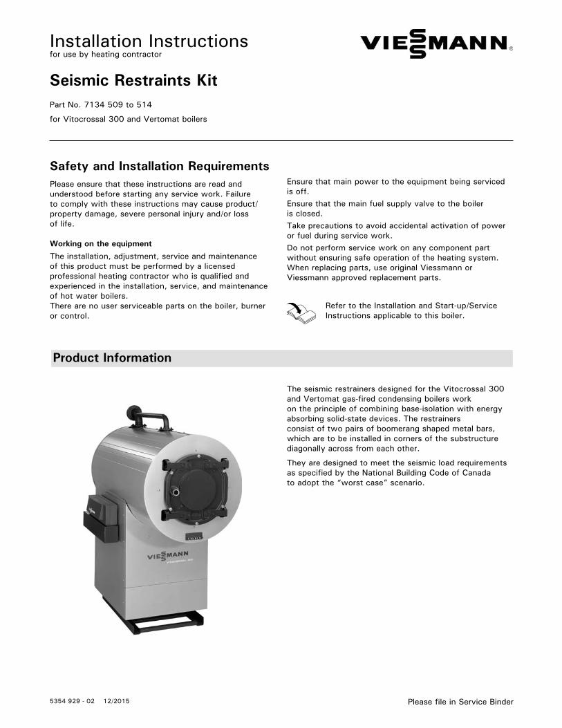
The seismic restrainers designed for the Vitocrossal 300 and Vertomat gas-fired condensing boilers work on the principle of combining base-isolation with energy absorbing solid-state devices. The restrainersconsist of two pairs of boomerang shaped metal bars, which are to be installed in corners of the substructurediagonally across from each other.
They are designed to meet the seismic load requirements as specified by the National Building Code of Canada to adopt the “worst case” scenario.
Ensure that main power to the equipment being serviced is off.Ensure that the main fuel supply valve to the boiler is closed.Take precautions to avoid accidental activation of power or fuel during service work.Do not perform service work on any component part without ensuring safe operation of the heating system. When replacing parts, use original Viessmann or Viessmann approved replacement parts.
Refer to the Installation and Start-up/ServiceInstructions applicable to this boiler.
Safety and Installation RequirementsPlease ensure that these instructions are read and understood before starting any service work. Failure to comply with these instructions may cause product/property damage, severe personal injury and/or loss of life.
Working on the equipment
The installation, adjustment, service and maintenance of this product must be performed by a licensed professional heating contractor who is qualified and experienced in the installation, service, and maintenance of hot water boilers.There are no user serviceable parts on the boiler, burner or control.
Seismic Restraints Kit Installation
5354 9
29 -
02
2
Standard Equipment
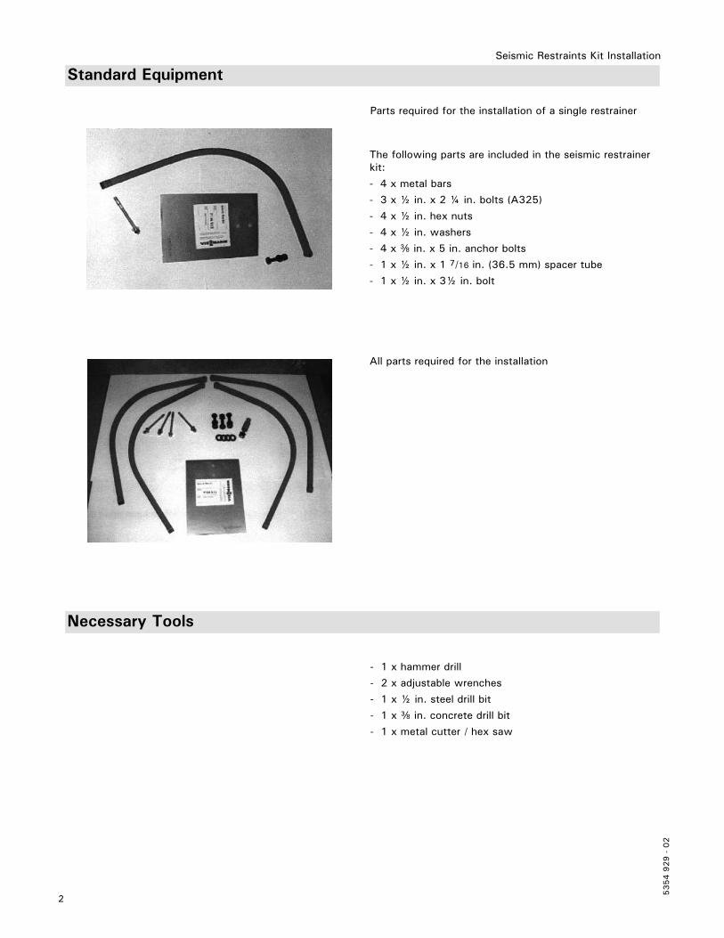
The following parts are included in the seismic restrainer kit:
- 4 x metal bars
- 3 x ½ in. x 2 ¼ in. bolts (A325)
- 4 x ½ in. hex nuts
- 4 x ½ in. washers
- 4 x e in. x 5 in. anchor bolts
- 1 x ½ in. x 1 7/16 in. (36.5 mm) spacer tube
- 1 x ½ in. x 3½ in. bolt
Parts required for the installation of a single restrainer
All parts required for the installation
Necessary Tools
- 1 x hammer drill
- 2 x adjustable wrenches
- 1 x ½ in. steel drill bit
- 1 x e in. concrete drill bit
- 1 x metal cutter / hex saw
3
5354 9
29 -
02
Seismic Restraints Kit Installation
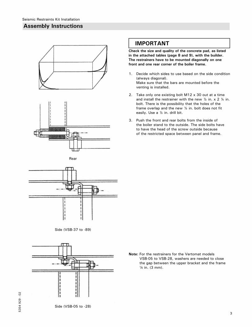
Assembly Instructions
IMPORTANTCheck the size and quality of the concrete pad, as listed in the attached tables (page 8 and 9), with the builder. The restrainers have to be mounted diagonally on one front and one rear corner of the boiler frame.
1. Decide which sides to use based on the side condition (always diagonal).
Make sure that the bars are mounted before the venting is installed.
2. Take only one existing bolt M12 x 30 out at a time and install the restrainer with the new ½ in. x 2 ¼ in. bolt. There is the possibility that the holes of the frame overlap and the new ½ in. bolt does not fit easily. Use a ½ in. drill bit.
3. Push the front and rear bolts from the inside of the boiler stand to the outside. The side bolts have to have the head of the screw outside because of the restricted space between panel and frame.
Note: For the restrainers for the Vertomat models VSB-05 to VSB-28, washers are needed to close the gap between the upper bracket and the frame d in. (3 mm).
Side (VSB-37 to -89)
Rear
Side (VSB-05 to -28)
Seismic Restraints Kit Installation
5354 9
29 -
02
4
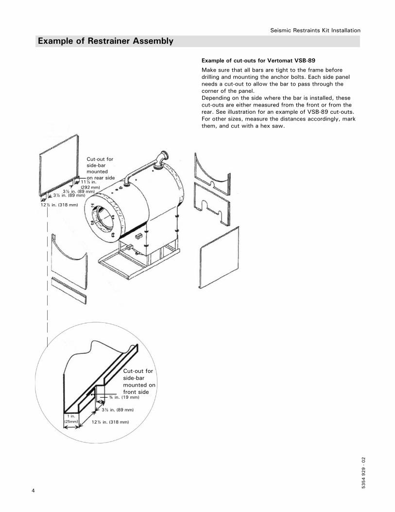
Cut-out forside-barmounted onfront side
Cut-out forside-barmountedon rear side
¾ in. (19 mm)
1 in.(25mm)
3½ in. (89 mm)
12½ in. (318 mm)
3½ in. (89 mm)
11½ in. (292 mm)
3½ in. (89 mm)
12½ in. (318 mm)
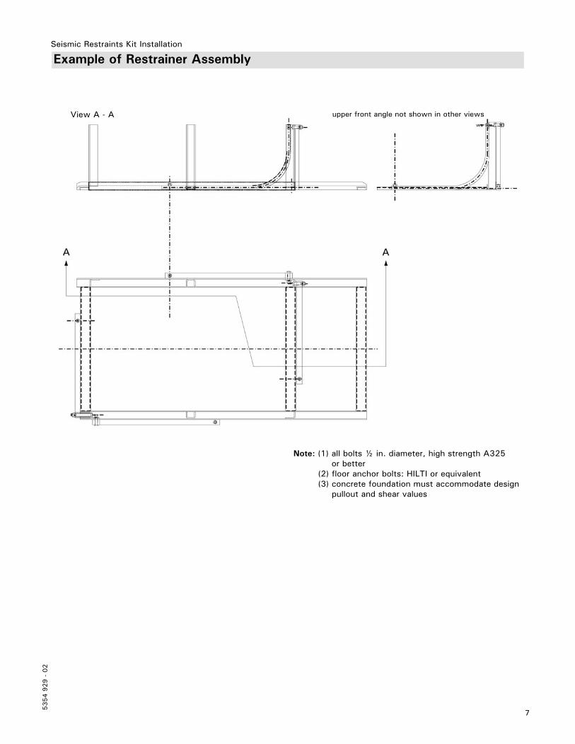
Example of Restrainer Assembly
Example of cut-outs for Vertomat VSB-89
Make sure that all bars are tight to the frame before drilling and mounting the anchor bolts. Each side panel needs a cut-out to allow the bar to pass through the corner of the panel.Depending on the side where the bar is installed, these cut-outs are either measured from the front or from the rear. See illustration for an example of VSB-89 cut-outs. For other sizes, measure the distances accordingly, mark them, and cut with a hex saw.
5
5354 9
29 -
02
Seismic Restraints Kit Installation
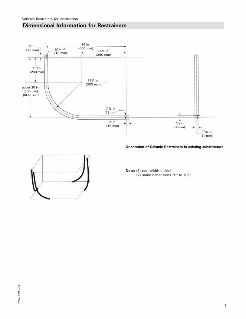
Dimensional Information for Restrainers
26 in.(660 mm)
14d in.(360 mm)
11c in.(300 mm)
about 20 in. (500 mm) (fit to suit)
77/8 in.(200 mm)
7½ in.(13 mm)
f in.(15 mm)
1/25 in.(1 mm)
f in.(15 mm)
7½ in.(13 mm)
1/25 in.(1 mm)
Note: (1) req. width thick (2) some dimensions “fit to suit”
Orientation of Seismic Restrainers in existing substructure
Seismic Restraints Kit Installation
5354 9
29 -
02
6
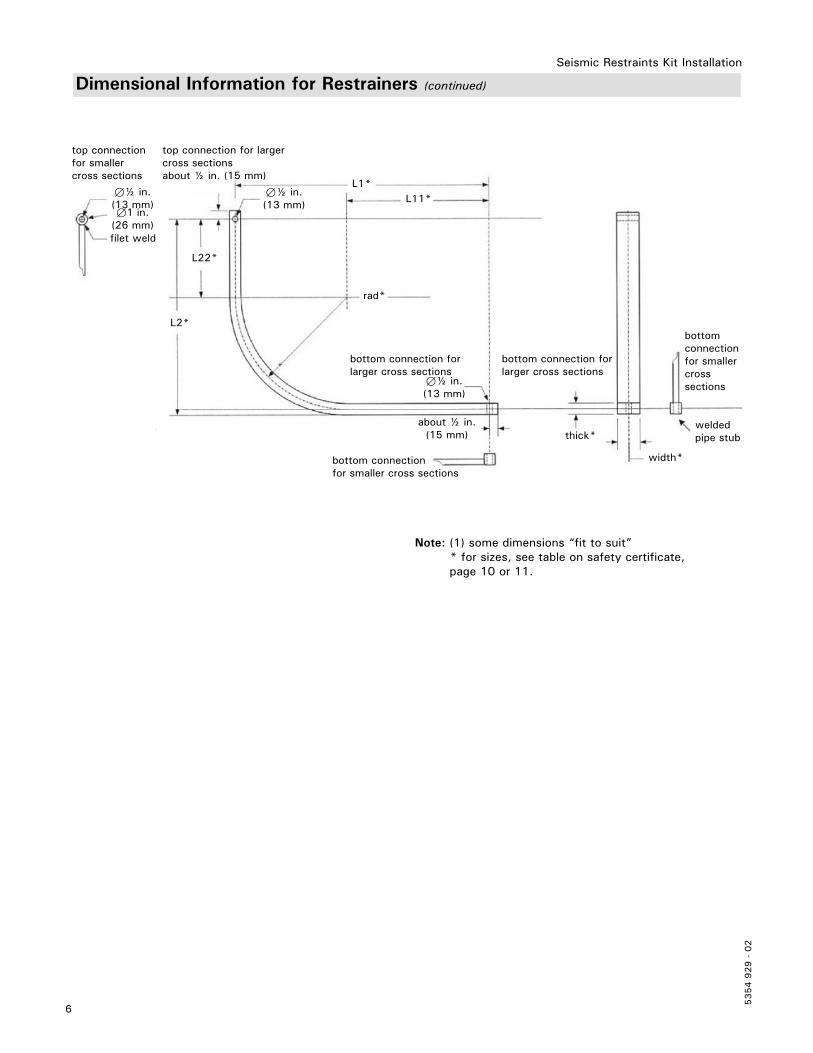
Dimensional Information for Restrainers (continued)
Note: (1) some dimensions “fit to suit” * for sizes, see table on safety certificate, page 10 or 11.
top connection for smaller cross sections
top connection for largercross sectionsabout ½ in. (15 mm)
filet weld
bottom connection for larger cross sections
bottom connection for smaller cross sections
bottom connection forlarger cross sections
thick*
width*bottom connectionfor smaller cross sections
welded pipe stub
about ½ in. (15 mm)
7½ in.(13 mm)71 in.
(26 mm)
7½ in.(13 mm)
7½ in.(13 mm)
L1*
L2*
L22*
L11*
rad*
7
5354 9
29 -
02
Seismic Restraints Kit Installation
Example of Restrainer Assembly
Note: (1) all bolts ½ in. diameter, high strength A325 or better
(2) floor anchor bolts: HILTI or equivalent (3) concrete foundation must accommodate design
pullout and shear values
View A - A upper front angle not shown in other views
Seismic Restraints Kit Installation
5354 9
29 -
02
8
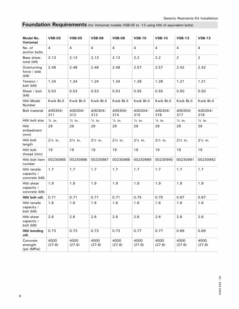
Foundation Requirements (for Vertomat models VSB-05 to -13 using Hilti of equivalent bolts)
Model No.Vertomat
VSB-05 VSB-05 VSB-08 VSB-08 VSB-10 VSB-10 VSB-13 VSB-13
No. of anchor bolts
4 4 4 4 4 4 4 4
Base shear, total (kN)
2.13 2.13 2.13 2.13 2.2 2.2 2 2
Overturningforce / side (kN)
2.48 2.48 2.48 2.48 2.57 2.57 2.42 2.42
Tension / bolt (kN)
1.24 1.24 1.24 1.24 1.28 1.28 1.21 1.21
Shear / bolt (kN)
0.53 0.53 0.53 0.53 0.55 0.55 0.50 0.50
Hilti Model Number
Kwik Bt.II Kwik Bt.II Kwik Bt.II Kwik Bt.II Kwik Bt.II Kwik Bt.II Kwik Bt.II Kwik Bt.II
Bolt material AISI304/ 311
AISI304/ 312
AISI304/ 313
AISI304/ 314
AISI304/ 315
AISI304/ 316
AISI304/ 317
AISI304/ 318
Hilti bolt size a in. a in. a in. a in. a in. a in. a in. a in.
Hilti embedment(mm)
29 29 29 29 29 29 29 29
Hilti bolt length
2a in. 2a in. 2a in. 2a in. 2a in. 2a in. 2a in. 2a in.
Hilti bolt thread (mm)
19 19 19 19 19 19 19 19
Hilti bolt item number
00230985 00230986 00230987 00230988 00230989 00230990 00230991 00230992
Hilti tensile capacity /concrete (kN)
1.7 1.7 1.7 1.7 1.7 1.7 1.7 1.7
Hilti shear capacity /concrete (kN)
1.9 1.9 1.9 1.9 1.9 1.9 1.9 1.9
Hilti bolt util. 0.71 0.71 0.71 0.71 0.75 0.75 0.67 0.67
Hilti tensile capacity /bolt (kN)
1.6 1.6 1.6 1.6 1.6 1.6 1.6 1.6
Hilti shear capacity /bolt (kN)
2.6 2.6 2.6 2.6 2.6 2.6 2.6 2.6
Hilti bonding util.
0.73 0.73 0.73 0.73 0.77 0.77 0.69 0.69
Concrete strength(psi (MPa))
4000 (27.6)
4000 (27.6)
4000 (27.6)
4000 (27.6)
4000 (27.6)
4000 (27.6)
4000 (27.6)
4000 (27.6)
9
5354 9
29 -
02
Seismic Restraints Kit Installation
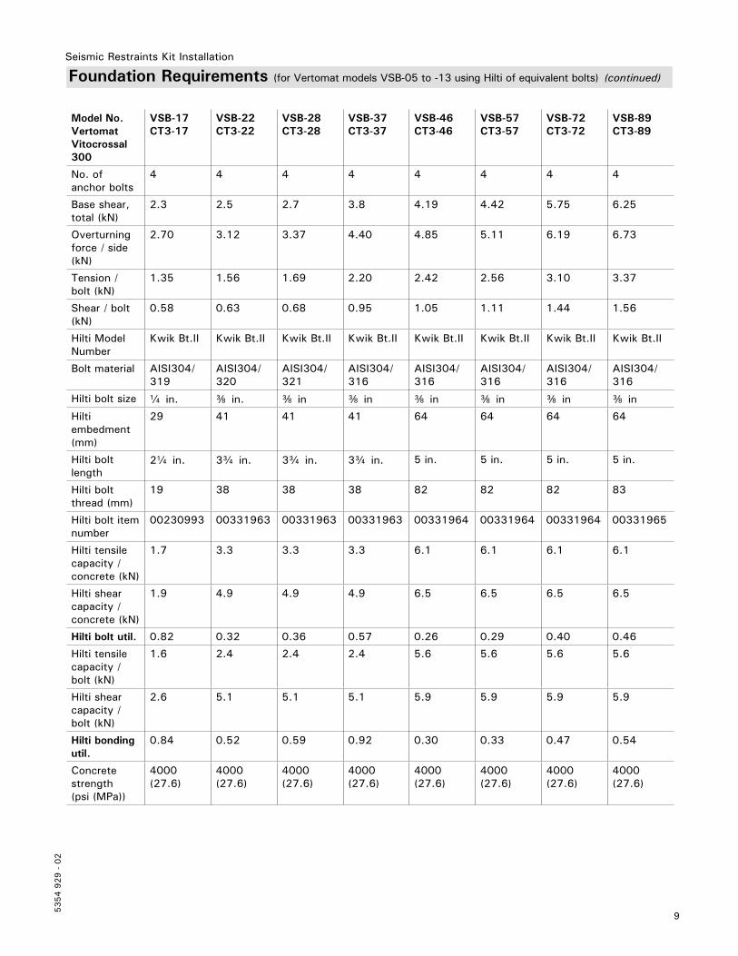
Foundation Requirements (for Vertomat models VSB-05 to -13 using Hilti of equivalent bolts) (continued)
Model No.VertomatVitocrossal 300
VSB-17CT3-17
VSB-22CT3-22
VSB-28CT3-28
VSB-37CT3-37
VSB-46CT3-46
VSB-57CT3-57
VSB-72CT3-72
VSB-89CT3-89
No. of anchor bolts
4 4 4 4 4 4 4 4
Base shear, total (kN)
2.3 2.5 2.7 3.8 4.19 4.42 5.75 6.25
Overturningforce / side (kN)
2.70 3.12 3.37 4.40 4.85 5.11 6.19 6.73
Tension / bolt (kN)
1.35 1.56 1.69 2.20 2.42 2.56 3.10 3.37
Shear / bolt (kN)
0.58 0.63 0.68 0.95 1.05 1.11 1.44 1.56
Hilti Model Number
Kwik Bt.II Kwik Bt.II Kwik Bt.II Kwik Bt.II Kwik Bt.II Kwik Bt.II Kwik Bt.II Kwik Bt.II
Bolt material AISI304/ 319
AISI304/ 320
AISI304/ 321
AISI304/ 316
AISI304/ 316
AISI304/ 316
AISI304/ 316
AISI304/ 316
Hilti bolt size a in. e in. e in e in e in e in e in e in
Hilti embedment(mm)
29 41 41 41 64 64 64 64
Hilti bolt length
2a in. 3c in. 3c in. 3c in. 5 in. 5 in. 5 in. 5 in.
Hilti bolt thread (mm)
19 38 38 38 82 82 82 83
Hilti bolt item number
00230993 00331963 00331963 00331963 00331964 00331964 00331964 00331965
Hilti tensile capacity /concrete (kN)
1.7 3.3 3.3 3.3 6.1 6.1 6.1 6.1
Hilti shear capacity /concrete (kN)
1.9 4.9 4.9 4.9 6.5 6.5 6.5 6.5
Hilti bolt util. 0.82 0.32 0.36 0.57 0.26 0.29 0.40 0.46
Hilti tensile capacity /bolt (kN)
1.6 2.4 2.4 2.4 5.6 5.6 5.6 5.6
Hilti shear capacity /bolt (kN)
2.6 5.1 5.1 5.1 5.9 5.9 5.9 5.9
Hilti bonding util.
0.84 0.52 0.59 0.92 0.30 0.33 0.47 0.54
Concrete strength(psi (MPa))
4000 (27.6)
4000 (27.6)
4000 (27.6)
4000 (27.6)
4000 (27.6)
4000 (27.6)
4000 (27.6)
4000 (27.6)
Seismic Restraints Kit Installation
5354 9
29 -
02
10
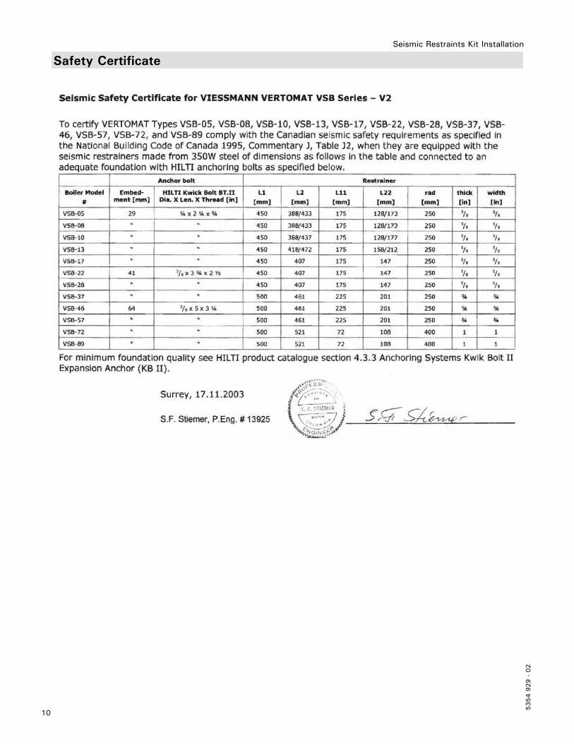
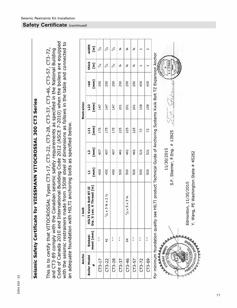
Safety Certificate
11
5354 9
29 -
02
Seismic Restraints Kit Installation
Safety Certificate (continued)
Tec
hnic
al in
form
atio
n su
bjec
t to
cha
nge
witho
ut n
otic
e.Pr
inte
d on
env
ironm
enta
lly f
riend
ly
(rec
ycle
d an
d re
cycl
able
) pa
per.
5354 9
29 -
02
Seismic Restraints Kit Installation


![[ORAL ARGUMENT NOT SCHEDULED] No. 09-5354 IN THE …](https://img.pdfslide.us/doc/110x75/616a697911a7b741a3523673/oral-argument-not-scheduled-no-09-5354-in-the-.jpg)