Embed Size (px)
Citation preview
Copyright © 2013 Meriam
5150 Series HART® Communicator
9R253-G May 2018
5150 User’s Manual Page 2
General information
Disclaimer Every precaution has been taken in the preparation of this manual. Nevertheless, Meriam assumes no responsibility for errors or omissions or any damages resulting from the use of the information contained in this publication, including, without limitation, incidental, special, direct or consequential damages. MERIAM MAKES NO REPRESENTATIONS OR WARRANTIES WITH RESPECT TO THE ACCURACY OR COMPLETENESS OF THE CONTENTS HEREOF AND SPECIFICALLY DISCLAIMS ANY IMPLIED WARRANTIES OF MERCHANTABILITY OR FITNESS FOR ANY PARTICULAR PURPOSE. Meriam reserves the right to revise this publication and to make changes from time to time in the content hereof without obligation to notify any person of such revision or changes.
In no event shall Meriam be liable for any indirect, special, incidental, consequential, or punitive damages or for any lost profits arising out of or relating to any services provided by Meriam or its affiliates.
It is not possible for Meriam to identify all foreseeable uses or misuses, therefore all persons involved in commissioning, using, or maintaining this product must satisfy their self that each intended application is acceptable.
Copyright This publication is proprietary to Meriam and no ownership rights are transferred. Neither this manual, nor any of the material contained herein, may be reproduced without the prior written consent of Meriam.
Trademark information
HART Communication Foundation HART® and HART Communication Foundation are used by permission of the HART® Communication Foundation.
All other trademarks are the property of their respective owners.
9R253-G May 2018
5150 User’s Manual Page 3
Glossary Words and phrases with their definitions.
Button or key • A button always refers to an area on the screen that you can
click to select functionality.
• A key always refers to hardware push buttons on the keyboard that you can press.
DD or Device Description files • Manufacturers create HART® compliant Device Description
(DD) files that reside on the 5150. You may need to check for updates to the DD files from time to time.
Highlight This manual uses the word highlight in two ways:
1. As a noun: highlight refers to an icon or a menu line that has the focus on-screen at any given time.
2. As a verb: highlight refers to:
a. Pressing the arrow keys or Advance key to change the focus to a new button.
b. Pressing and holding a button on-screen for one second to change the focus to a new button.
9R253-G May 2018
5150 User’s Manual Page 4
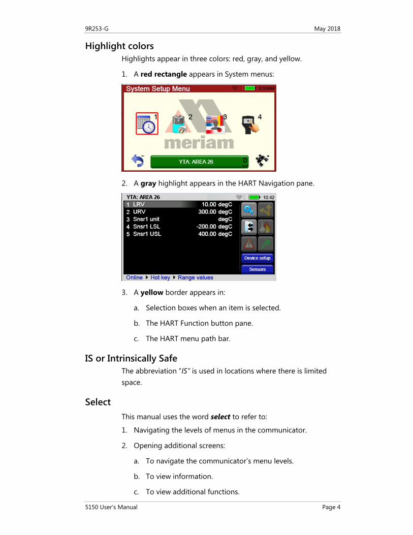
Highlight colors Highlights appear in three colors: red, gray, and yellow.
1. A red rectangle appears in System menus:
2. A gray highlight appears in the HART Navigation pane.
3. A yellow border appears in:
a. Selection boxes when an item is selected.
b. The HART Function button pane.
c. The HART menu path bar.
IS or Intrinsically Safe The abbreviation “IS” is used in locations where there is limited space.
Select This manual uses the word select to refer to:
1. Navigating the levels of menus in the communicator.
2. Opening additional screens:
a. To navigate the communicator’s menu levels.
b. To view information.
c. To view additional functions.
9R253-G May 2018
5150 User’s Manual Page 5
3. Performing some task on the communicator.
Note: Highlight an on-screen button you want to choose and select it.
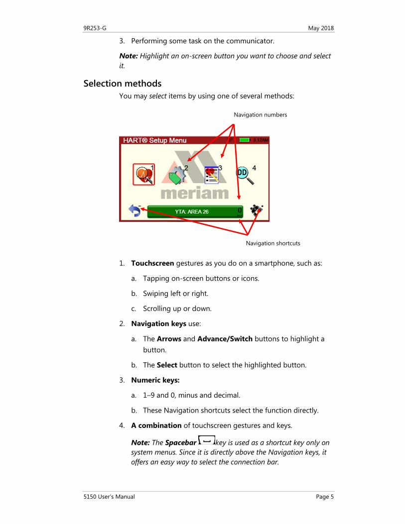
Selection methods You may select items by using one of several methods:
1. Touchscreen gestures as you do on a smartphone, such as:
a. Tapping on-screen buttons or icons.
b. Swiping left or right.
c. Scrolling up or down.
2. Navigation keys use:
a. The Arrows and Advance/Switch buttons to highlight a button.
b. The Select button to select the highlighted button.
3. Numeric keys:
a. 1–9 and 0, minus and decimal.
b. These Navigation shortcuts select the function directly.
4. A combination of touchscreen gestures and keys.
Note: The Spacebar key is used as a shortcut key only on system menus. Since it is directly above the Navigation keys, it offers an easy way to select the connection bar.
Navigation numbers
Navigation shortcuts
9R253-G May 2018
5150 User’s Manual Page 6
Standby or sleep This manual uses the word standby mode to describe putting the communicator into an energy-saving mode, where it uses very little power. Some use the word sleep mode instead of standby.
9R253-G May 2018
5150 User’s Manual Page 7
General Warnings and Cautions
Preventing injury
Failure to follow all instructions could result in injury:
• Read. • Understand. • Follow all safety warnings and instructions provided with this
product. • Meet or exceed your employer’s safety practices.
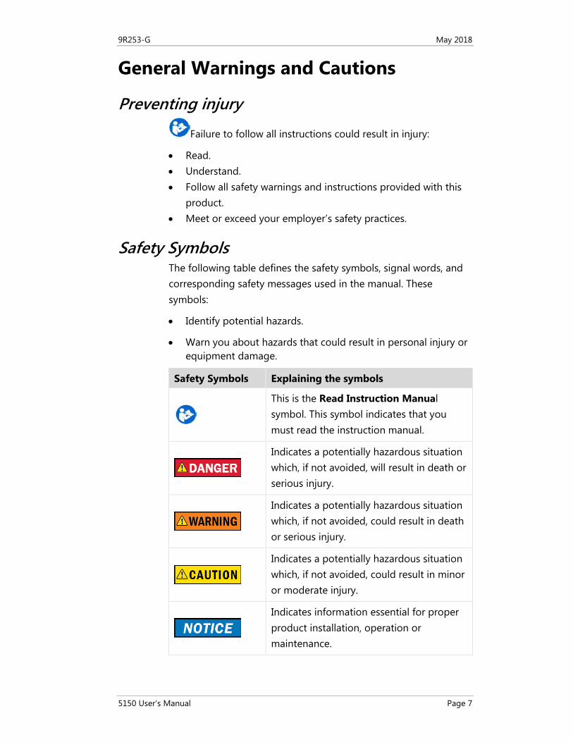
Safety Symbols The following table defines the safety symbols, signal words, and corresponding safety messages used in the manual. These symbols:
• Identify potential hazards.
• Warn you about hazards that could result in personal injury or equipment damage.
Safety Symbols Explaining the symbols
This is the Read Instruction Manual symbol. This symbol indicates that you must read the instruction manual.
Indicates a potentially hazardous situation which, if not avoided, will result in death or serious injury.
Indicates a potentially hazardous situation which, if not avoided, could result in death or serious injury.
Indicates a potentially hazardous situation which, if not avoided, could result in minor or moderate injury.
Indicates information essential for proper product installation, operation or maintenance.
9R253-G May 2018
5150 User’s Manual Page 8
Contents General information .......................................................................2
Disclaimer ................................................................................................ 2
Copyright ................................................................................................. 2
Trademark information .......................................................................... 2 HART Communication Foundation ......................................... 2
Glossary .................................................................................................... 3 Button or key.............................................................................. 3 DD or Device Description files ................................................. 3 Highlight ..................................................................................... 3 Highlight colors ......................................................................... 4 IS or Intrinsically Safe ................................................................ 4 Select ........................................................................................... 4 Selection methods ..................................................................... 5 Standby or sleep ........................................................................ 6
General Warnings and Cautions ...................................................7
Preventing injury ..................................................................................... 7
Safety Symbols......................................................................................... 7
Contents ..........................................................................................8
Installing or removing the battery pack .................................... 16
Preventing explosions ........................................................................... 16
Installing the battery ............................................................................. 16
Don’t over tighten ................................................................................. 16
Removing the battery ........................................................................... 17
Charging the battery pack six (6) hours .............................................. 17
Memory System Card ................................................................... 18
Uses for the memory card .................................................................... 18
Use only with the 5150 ......................................................................... 18
Replace the card with Meriam Z9P780 ............................................... 18
Remove the battery pack to remove the card .................................... 18
9R253-G May 2018
5150 User’s Manual Page 9
Remove the memory card .................................................................... 19
Replace the memory card ..................................................................... 19
5150 Series HART Communicator Overview ............................. 20
Full function HART ................................................................................ 20
Diagram of the 5150 ............................................................................ 20
Touchscreen ........................................................................................... 21 Touchscreen: Display details .................................................. 21 Touchscreen: Two menu systems .......................................... 21
Touchscreen: System menus ................................................................ 21
Touchscreen: HART menus ................................................................... 22 HART menus appear when connected to HART devices ... 22 Sample HART menu display ................................................... 22
5150 Operating Instructions ....................................................... 23
Power key functions .............................................................................. 23 Turn on ...................................................................................... 23 Standby ..................................................................................... 23 Standby turns off after two hours ......................................... 23 Resume ..................................................................................... 23 Turn off ..................................................................................... 24
Backlight: reducing intensity ................................................................ 24 Pressing the Backlight key ...................................................... 24 Reducing intensity improves battery life .............................. 24
Backlight: settings for timeout ............................................................. 25 Changing the timeout setting to save battery life .............. 25
Standby: settings for timeout ............................................................... 25 Change the timeout settings to save battery life ................ 25 Navigating to the Standby timeout settings ....................... 26
Timeout: Backlight and Standby are cumulative ............................... 27 An example of the cumulative timeouts .............................. 27
The battery pack life ............................................................................. 28 Keep charging it....................................................................... 28 For portable use....................................................................... 28 Advanced battery fuel gauge................................................. 28 Low battery level alerts for the XL Battery ........................... 29
9R253-G May 2018
5150 User’s Manual Page 10
Standby mode and the alerts ................................................ 29
The charging cradle .............................................................................. 30 Connections in the charging cradle ...................................... 30 Automatically recharges ......................................................... 30 Charging indicator ................................................................... 30 Connecting to a computer ..................................................... 31 Insert the communicator not the battery ............................. 31 Not intrinsically safe ................................................................ 31
Kickstand: a better angle to view the display ..................................... 32
Loop Communication Jacks & Field-wiring practices ........................ 33 Loop Communication Jacks ................................................... 33 Field-wiring practices .............................................................. 33
Keyboard overview ................................................................................ 34 Arranged by frequency of use ............................................... 34 Alphabetic keys ........................................................................ 34
Keyboard functions ............................................................................... 35 Decision keys & buttons ......................................................... 35
Keyboard: Navigation & Information ................................................. 36 Numeric keys............................................................................ 36 Fixed function keys .................................................................. 36
Keyboard: the on-screen keyboard ...................................................... 37 Use both the dedicated and on-screen keyboards ............. 37 ISO Latin-1 Character Set ....................................................... 37 181 characters on the touchscreen ....................................... 38 Limited character sets ............................................................. 39 Limited number of characters ................................................ 40 Navigating in the screen ......................................................... 40 Navigating the keysets ........................................................... 41 Diagram of Keyset #1 ............................................................. 41 Touchscreen: Keysets #2–5 .................................................... 42
Navigating the Communicator ............................................................ 43 System Menus .......................................................................... 43 Communicator status line ...................................................... 43 Communicator status line explained .................................... 44 Using the bottom row of icons to navigate ......................... 44 Back key: go back to the previous system menu ................ 44
9R253-G May 2018
5150 User’s Manual Page 11
HART navigation and connection status ................................... 45
Navigating to the HART Setup Menu ................................... 45 Viewing the HART Setup Menu and navigation options ... 45 Yellow connection bar ............................................................ 45 Green connection bar ............................................................. 45 Restart polling .......................................................................... 46 Display a list of devices ........................................................... 46
Main system menus ..................................................................... 47
Connected main menu ......................................................................... 47
Main menu icons ................................................................................... 47
System Setup Menu ............................................................................... 48 System Setup menu icons ...................................................... 48 Descriptions of Setup icons ................................................... 48 Date/Time Setup: System menu ............................................ 49
Power Setup: System Menu .................................................................. 50 Power Setup Menu .................................................................. 50 Power Setup Icons ................................................................... 50
Language Selection: System Menu ...................................................... 51 Display available languages ................................................... 51 Select your language .............................................................. 51
Language Selection: Displayed ............................................................ 52 Turn off and Turn on ............................................................... 52 New language displayed ........................................................ 52 Some screens not translated .................................................. 52
Calibrating the touchscreen: System Menu ........................................ 53 Begin calibrating the touchscreen......................................... 53 Accept the new settings or keep the old settings ............... 53
System Information: System Menu ...................................................... 54 View status details about the communicator ...................... 54 System Information ................................................................. 54
HART Setup Menu ........................................................................ 55
HART Setup Menu ................................................................................. 55
HART Setup icons .................................................................................. 55
Shifting the highlight in HART menus ................................................ 56
9R253-G May 2018
5150 User’s Manual Page 12
Connected HART devices ....................................................... 56 Three navigation panes .......................................................... 56 Shifting the highlight .............................................................. 56 The Navigation pane has a gray highlight ........................... 56 Yellow highlight on the menu path bar................................ 57 Yellow highlight on a Function button ................................. 57
Status Line for the connecting device .................................................. 58 Status line diagram ................................................................. 58 Status Line descriptions .......................................................... 58
DD files control HART menus .............................................................. 59 Device Description (DD) files ................................................. 59 Menu Line Items ...................................................................... 59 DD files control HART menus ................................................ 59
Function buttons in HART menus ........................................................ 60 Navigating the Function buttons .......................................... 60 Scroll up or down in the Function pane ............................... 60 Explaining the Function buttons............................................ 61 More Function buttons ........................................................... 62
Creating Shortcuts ................................................................................. 63 New shortcut button ............................................................... 63 Managing shortcuts ................................................................ 63 Invalid shortcuts ...................................................................... 64
HART menu path bar ............................................................................ 64 Structure of the menu path bar ............................................. 64
Advanced Tools for HART ........................................................... 65
DD Browser and Offline Configuration ............................................... 65
DD Browser ............................................................................................ 65 Three ways to navigate in the DD Browser .......................... 65 Cancel button in DD Browser................................................. 66 Use the DD Browser to view a list of manufacturers .......... 66 Navigate lists in a complete circle ......................................... 67 View a list of device names .................................................... 67 View a list of device revisions ................................................ 68 The right side of the screen (gray area) ................................ 68
Offline Configuration ............................................................................ 68 Offline Configuration navigation ........................................... 68
9R253-G May 2018
5150 User’s Manual Page 13
Two ways to use the offline configuration ........................... 69 What does <All> configurations display on the first screen? ................................................................................................... 69 Creating a new configuration ................................................ 70 Confirm you want to create an offline configuration ......... 70 Wait while the 5150 initiates the offline device .................. 71 Blue connection bar ................................................................ 71 Indicators in Offline Configuration ........................................ 72 Function buttons in Offline Configuration ........................... 74
HART Communication with the 5150 Series ............................. 75
Maintain field devices ........................................................................... 75
HART commands ................................................................................... 75
Device Description file (DD) uses ......................................................... 75
Updating your communicator with DDs ............................................. 75
Connecting the 5150 to Smart Transmitters with HART technology76 Banana Jacks ............................................................................ 76 Wiring diagram: Loop resistance < 250 Ω ........................... 76 Wiring diagram: loop resistance > 250 Ω ............................ 77
Three states of HART communication ................................................. 78 Gray connection bar: No device found ................................. 78 Gray connection bar: Initiating .............................................. 78 Gray connection bar: No actions ........................................... 78 Yellow connection bar: Number of Devices Found ............. 78 Display all devices ................................................................... 79 Select a device ......................................................................... 79 Green connection bar: connected ......................................... 79
Specific and Generic HART communication ....................................... 80 Find specific devices ................................................................ 80 Find generic devices ................................................................ 80 Generic starts automatically ................................................... 80 Generic mode running ............................................................ 81
Managing Configuration Files ............................................................. 81 The Configuration Option button ......................................... 81 Four configuration options .................................................... 81 Be careful when retrieving a configuration .......................... 84
Troubleshooting HART Communications .................................. 85
9R253-G May 2018
5150 User’s Manual Page 14
Troubleshooting: No Devices Found .................................................... 85
Troubleshooting: Generic...................................................................... 86
Troubleshooting: Multiple Devices ....................................................... 86
Updating communicator software ............................................. 86
Specifications ................................................................................ 87
Approvals ............................................................................................... 87 5150X Intrinsically Safe model ............................................... 87 5150 General Purpose model ................................................ 87
Display specifications ............................................................................ 87
Ingress specifications ............................................................................ 87
Power ...................................................................................................... 87
Dimensional specifications ................................................................... 88
Battery life (Approximate) .................................................................... 89
Temperature specifications .................................................................. 89
Communication connections ............................................................... 89
Memory card .......................................................................................... 89
Safety ............................................................................................. 90
Intrinsically Safe Model ......................................................................... 90
Hazardous and non-hazardous locations (safe locations) ............... 90
Example of an Intrinsically Safe name plate ...................................... 90
Hazardous locations: Warnings & Cautions ...................................... 91 No substitutions ...................................................................... 91 Preventing explosions ............................................................. 91 Restrictions on electrical connections .................................. 91 Restrictions in hazardous locations ....................................... 91
Intrinsic Safety Control Drawing ......................................................... 92
EC Declaration of Conformity .............................................................. 93
EC Declaration of Conformity (Intrinsically Safe)Error! Bookmark not defined.
Maintenance and cleaning .......................................................... 94
Recommendations for your battery ..................................................... 94
9R253-G May 2018
5150 User’s Manual Page 15
Make it last longer ................................................................... 94 Storing your 5150 for more than 30 days? .......................... 94 Two factors affect your battery’s life in storage .................. 95
Waste Electrical and Electronic Equipment (WEEE), Directive 2012/19/EU............................................................................................ 95
European Union only .............................................................. 95 European Union Product Category ....................................... 95 US government agencies ....................................................... 96 Other countries ........................................................................ 96
Part numbers ................................................................................ 97
Meriam spare-part numbers .................................................. 97
Help ............................................................................................... 98
Register your product ............................................................................ 98
Find downloads and documents .......................................................... 98
For repair or calibration ....................................................................... 99 Contact Meriam for repair or calibration ............................. 99 You have three options for requesting service: ................... 99 Before you ship anything to Meriam .................................. 100 Do you have any questions? Call Meriam .......................... 100 Ship the box to ...................................................................... 100
Meriam Contact Information ............................................................. 101 Address ................................................................................... 101 Telephone ............................................................................... 101 Fax ........................................................................................... 101 E-mail addresses .................................................................... 101 Website ................................................................................... 101 Find a local Meriam representative ..................................... 101
9R253-G May 2018
5150 User’s Manual Page 16
Installing or removing the battery pack
Preventing explosions
• Do not use any battery pack other than the 5150 Series Pack Z9A820-X.
Installing the battery To install the battery pack:
1. Set the communicator enclosure with the display downward on a flat, stable surface.
2. Rest the battery pack in the battery pack compartment of the enclosure.
3. Leave a 1/2 in. gap (or 1.27 cm) between the battery pack and the connector on the communicator enclosure.
4. Slide the battery pack inside the enclosure until the connectors mate completely and the screws align with the threaded inserts on the communicator body.
Note: Two standard 6-32 screws hold the battery pack in the communicator. These screws are a part of the battery pack. They have hexagonal sockets that require a 7/64 in. hex key wrench.
5. Thread the screws into the inserts to complete the installation.
Note: The 7/64 in. hex key wrench is included with the unit.
Don’t over tighten
Do not over tighten the screws when you install the battery pack. Over tightening screws can cause damage the communicator.
Note: Maximum torque should not exceed seven (7) in-lb. (or 0.79 N · m).
9R253-G May 2018
5150 User’s Manual Page 17
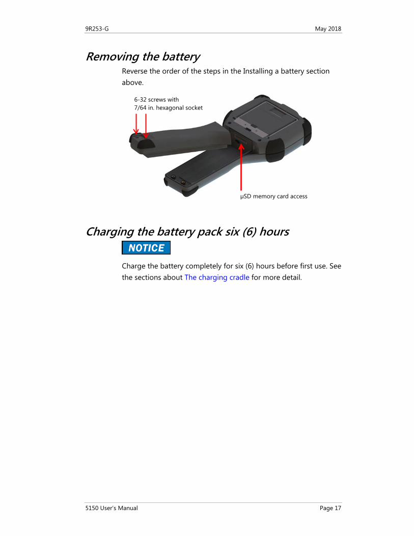
Removing the battery Reverse the order of the steps in the Installing a battery section above.
Charging the battery pack six (6) hours
Charge the battery completely for six (6) hours before first use. See the sections about The charging cradle for more detail.
6-32 screws with 7/64 in. hexagonal socket
µSD memory card access
9R253-G May 2018
5150 User’s Manual Page 18
Memory System Card
Uses for the memory card Meriam ships a µSD memory system card installed in the communicator. This system card is necessary for the following uses:
• Storage of required software.
• Software updates.
• HART DD files.
• Device configuration files.
Use only with the 5150 The µSD memory system card is not intended for use unrelated to the operation of the communicator. The 5150 Series System card must be installed to operate the communicator.
Note: While the µSD memory system card is in the 5150, there is no way to access the card except with the Meriam provided computer software.
Replace the card with Meriam Z9P780
If you need to replace the µSD card, it must be replaced with Meriam part number Z9P780 or the successor part number specified by Meriam.
• Replace the card only under the direction of Meriam personnel.
• Use of a non-system memory card voids the Intrinsic Safety Compliance.
Remove the battery pack to remove the card To remove and to replace the memory system card you must remove the battery first. See the Installing or removing the battery pack section for more details.
9R253-G May 2018
5150 User’s Manual Page 19
Remove the memory card Once you have removed the battery pack:
1. Press gently on the memory card to unlock it from the cardholder.
2. Carefully remove the memory card from the enclosure.
Note: Tweezers or small needle-nose pliers can be helpful in removing and inserting memory cards—apply gentle pressure only.
Replace the memory card Once you have removed the memory system card:
1. Insert the new memory card carefully into the cardholder. Verify the contacts are facing toward the back of the communicator and card label facing towards the front (screen side) of the communicator.
2. Be sure the memory card is resting in the holder before releasing it.
3. Gently press the card into the holder to lock it into place.
4. Install the battery pack and secure it to the communicator enclosure.
9R253-G May 2018
5150 User’s Manual Page 20
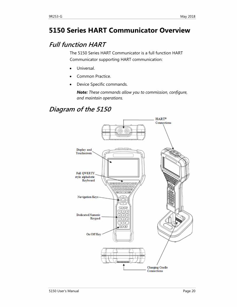
5150 Series HART Communicator Overview
Full function HART The 5150 Series HART Communicator is a full function HART Communicator supporting HART communication:
• Universal.
• Common Practice.
• Device Specific commands.
Note: These commands allow you to commission, configure, and maintain operations.
Diagram of the 5150
9R253-G May 2018
5150 User’s Manual Page 21
Touchscreen
Touchscreen: Display details The communicator has a 4.3-in. (10.9 cm) widescreen, backlit, TFT color touchscreen display:
• It has a 480 x 272 pixel resolution.
• The entire viewable area of the screen is an active touch surface.
• The touchscreen responds to and is optimized for finger presses—even when you are wearing gloves.
Important:
• No stylus is necessary.
• Never tap the screen with sharp objects – simply use your finger.
Touchscreen: Two menu systems The communicator displays two types of menus:
• System menus.
• HART menus.
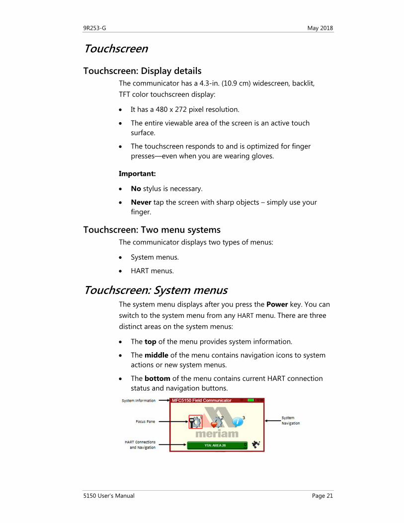
Touchscreen: System menus The system menu displays after you press the Power key. You can switch to the system menu from any HART menu. There are three distinct areas on the system menus:
• The top of the menu provides system information.
• The middle of the menu contains navigation icons to system actions or new system menus.
• The bottom of the menu contains current HART connection status and navigation buttons.
9R253-G May 2018
5150 User’s Manual Page 22
Touchscreen: HART menus
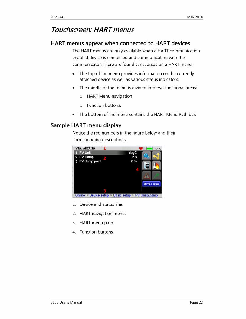
HART menus appear when connected to HART devices The HART menus are only available when a HART communication enabled device is connected and communicating with the communicator. There are four distinct areas on a HART menu:
• The top of the menu provides information on the currently attached device as well as various status indicators.
• The middle of the menu is divided into two functional areas:
o HART Menu navigation
o Function buttons.
• The bottom of the menu contains the HART Menu Path bar.
Sample HART menu display Notice the red numbers in the figure below and their corresponding descriptions:
1. Device and status line.
2. HART navigation menu.
3. HART menu path.
4. Function buttons.
1
2
3
4
9R253-G May 2018
5150 User’s Manual Page 23
5150 Operating Instructions
Power key functions
Turn on When you press and hold the Power key for two seconds, the communicator launches a complete system start sequence:
• The first screen displays the Meriam logo.
• The second screen displays a white screen with a list of drivers loading.
• The third screen displays the date and time.
• Now the communicator is ready to use.
Standby When you press the Power key and release, the communicator enters the standby mode (sometimes referred to as sleep mode):
• The screen is off and the communicator ignores most user input to conserve battery power.
• The on-board computer maintains the previous system state of functionality to resume quickly.
• Do not use the standby mode as a substitute for turning off the unit for extended periods of time.
Standby turns off after two hours
After two hours in Standby mode, the 5150 automatically turns off.
Resume When you press the Power key and release, the communicator quickly resumes operation from being in Standby:
• It returns to the exact state of functionality that it was in before entering standby.
• From the Power Setup Menu, users can enter a specific time for the unit to automatically enter the standby mode to conserve battery power.
9R253-G May 2018
5150 User’s Manual Page 24
Turn off When you hold the Power key until the screen turns off, the communicator is turned off:
• We recommend turning off the communicator as the best way to conserve battery life.
Note: The batteries will lose some power while not in use. For this reason, we recommend keeping the communicator in the charging cradle when not in use.
Backlight: reducing intensity
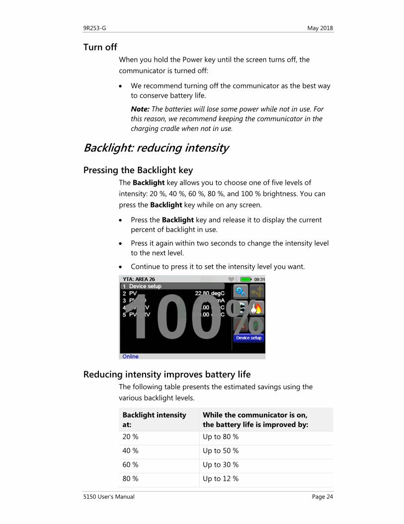
Pressing the Backlight key The Backlight key allows you to choose one of five levels of intensity: 20 %, 40 %, 60 %, 80 %, and 100 % brightness. You can press the Backlight key while on any screen.
• Press the Backlight key and release it to display the current percent of backlight in use.
• Press it again within two seconds to change the intensity level to the next level.
• Continue to press it to set the intensity level you want.
Reducing intensity improves battery life The following table presents the estimated savings using the various backlight levels.
Backlight intensity at:
While the communicator is on, the battery life is improved by:
20 % Up to 80 %
40 % Up to 50 %
60 % Up to 30 %
80 % Up to 12 %
9R253-G May 2018
5150 User’s Manual Page 25
Backlight: settings for timeout
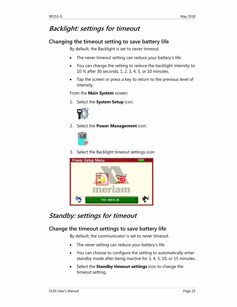
Changing the timeout setting to save battery life By default, the Backlight is set to never timeout.
• The never timeout setting can reduce your battery’s life.
• You can change the setting to reduce the backlight intensity to 10 % after 30 seconds, 1, 2, 3, 4, 5, or 10 minutes.
• Tap the screen or press a key to return to the previous level of intensity.
From the Main System screen:
1. Select the System Setup icon.
2. Select the Power Management icon.
3. Select the Backlight timeout settings icon.
Standby: settings for timeout
Change the timeout settings to save battery life By default, the communicator is set to never timeout.
• The never setting can reduce your battery’s life.
• You can choose to configure the setting to automatically enter standby mode after being inactive for 3, 4, 5, 10, or 15 minutes.
• Select the Standby timeout settings icon to change the timeout setting.
9R253-G May 2018
5150 User’s Manual Page 26
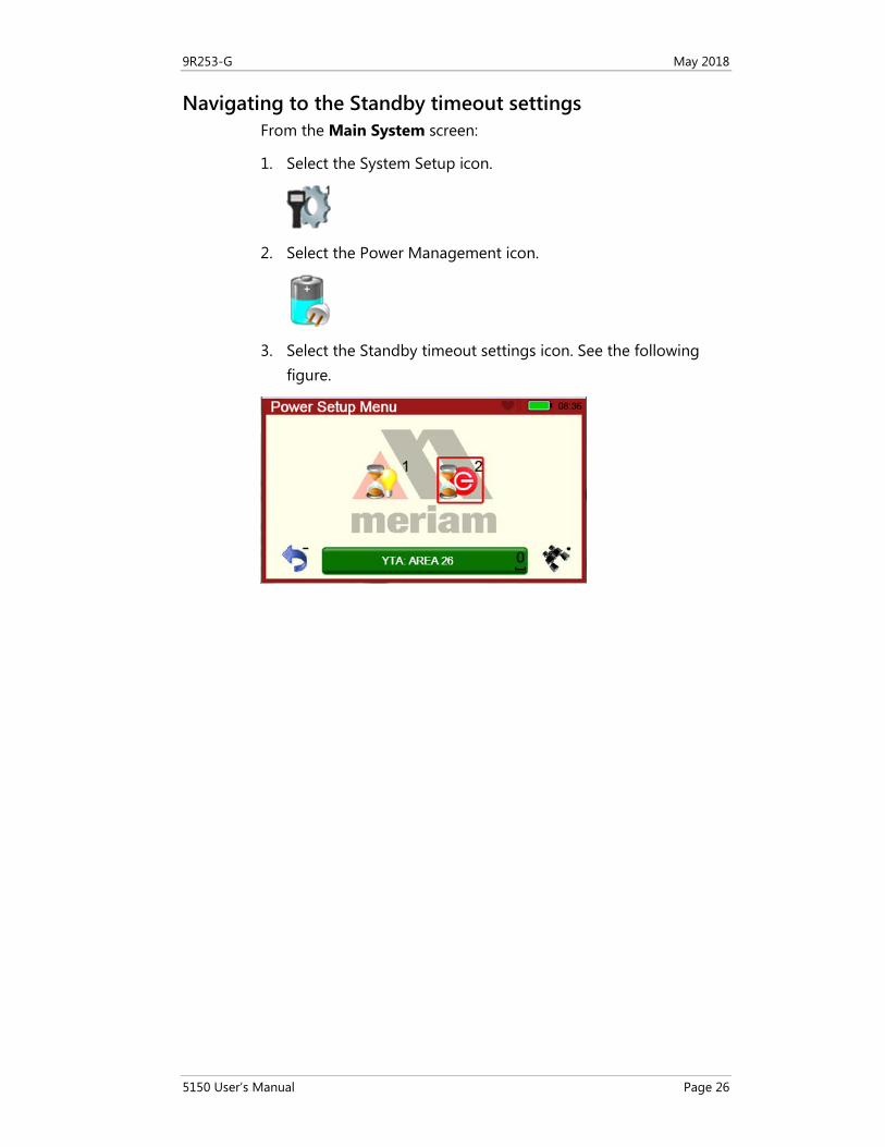
Navigating to the Standby timeout settings From the Main System screen:
1. Select the System Setup icon.
2. Select the Power Management icon.
3. Select the Standby timeout settings icon. See the following figure.
9R253-G May 2018
5150 User’s Manual Page 27
Timeout: Backlight and Standby are cumulative
An example of the cumulative timeouts • The Standby timeout period does not start
until the Backlight period has timed out. • To determine the amount of time before a communicator
automatically enters Standby mode, you must add the timeout settings for Backlight and Standby together.
If… Then…
You set the Backlight timeout to 30 seconds
• After the communicator is out of the cradle and it has no input for 30 seconds,
• The communicator reduces the intensity to 10 %.
You set the Standby timeout to 3 minutes
• 3 minutes and 30 seconds after the start of the Backlight timeout,
• The communicator enters Standby mode.
9R253-G May 2018
5150 User’s Manual Page 28
The battery pack life
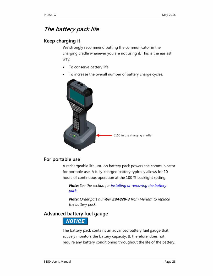
Keep charging it We strongly recommend putting the communicator in the charging cradle whenever you are not using it. This is the easiest way:
• To conserve battery life.
• To increase the overall number of battery charge cycles.
For portable use A rechargeable lithium-ion battery pack powers the communicator for portable use. A fully-charged battery typically allows for 10 hours of continuous operation at the 100 % backlight setting.
Note: See the section for Installing or removing the battery pack.
Note: Order part number Z9A820-3 from Meriam to replace the battery pack.
Advanced battery fuel gauge
The battery pack contains an advanced battery fuel gauge that actively monitors the battery capacity. It, therefore, does not require any battery conditioning throughout the life of the battery.
5150 in the charging cradle
9R253-G May 2018
5150 User’s Manual Page 29
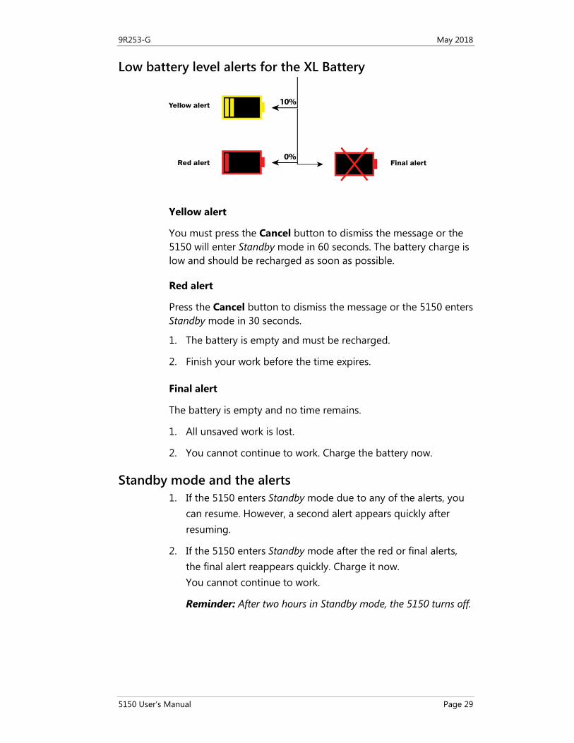
Low battery level alerts for the XL Battery
Yellow alert
You must press the Cancel button to dismiss the message or the 5150 will enter Standby mode in 60 seconds. The battery charge is low and should be recharged as soon as possible.
Red alert
Press the Cancel button to dismiss the message or the 5150 enters Standby mode in 30 seconds.
1. The battery is empty and must be recharged.
2. Finish your work before the time expires.
Final alert
The battery is empty and no time remains.
1. All unsaved work is lost.
2. You cannot continue to work. Charge the battery now.
Standby mode and the alerts 1. If the 5150 enters Standby mode due to any of the alerts, you
can resume. However, a second alert appears quickly after resuming.
2. If the 5150 enters Standby mode after the red or final alerts, the final alert reappears quickly. Charge it now. You cannot continue to work.
Reminder: After two hours in Standby mode, the 5150 turns off.
0%
10%Yellow alert
Red alert Final alert
9R253-G May 2018
5150 User’s Manual Page 30
The charging cradle
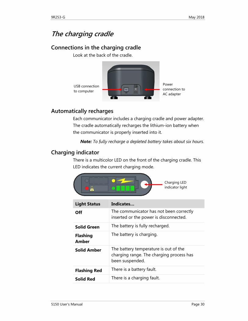
Connections in the charging cradle Look at the back of the cradle.
Automatically recharges Each communicator includes a charging cradle and power adapter. The cradle automatically recharges the lithium-ion battery when the communicator is properly inserted into it.
Note: To fully recharge a depleted battery takes about six hours.
Charging indicator There is a multicolor LED on the front of the charging cradle. This LED indicates the current charging mode.
Light Status Indicates…
Off The communicator has not been correctly inserted or the power is disconnected.
Solid Green The battery is fully recharged.
Flashing Amber
The battery is charging.
Solid Amber The battery temperature is out of the charging range. The charging process has been suspended.
Flashing Red There is a battery fault.
Solid Red There is a charging fault.
Power connection to AC adapter
USB connection to computer
Charging LED indicator light
9R253-G May 2018
5150 User’s Manual Page 31
Connecting to a computer You need to connect the USB cable to the charging cradle and to a computer to update files. The communicator must be in the cradle and turned on so it can update.
Note: See the section for Updating communicator software.
Insert the communicator not the battery
The charging cradle is not intended to recharge a battery itself. To properly recharge a battery pack, you must insert the battery into the communicator before placing it into the charging cradle.
Not intrinsically safe
The charging cradle is not rated for intrinsic safety.
• Do not charge in hazardous locations.
Note: Read the Safety section of this manual for more details about Intrinsic Safety.
Note: See the Safety section in this manual for more details and to view the Intrinsic Safety Control Drawing.
9R253-G May 2018
5150 User’s Manual Page 32
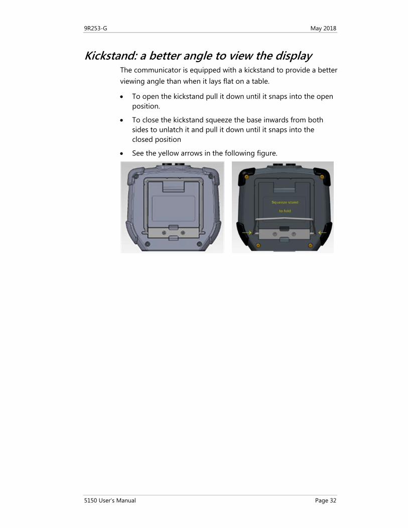
Kickstand: a better angle to view the display The communicator is equipped with a kickstand to provide a better viewing angle than when it lays flat on a table.
• To open the kickstand pull it down until it snaps into the open position.
• To close the kickstand squeeze the base inwards from both sides to unlatch it and pull it down until it snaps into the closed position
• See the yellow arrows in the following figure.
9R253-G May 2018
5150 User’s Manual Page 33
Loop Communication Jacks & Field-wiring practices
Loop Communication Jacks Loop Communication Jacks or Lead Set:
• All 5150 models are equipped with a standard size banana jacks on 0.75 in. or 1.9 cm center.
• The lead set supplied with the communicator has a standard banana plug on one end and mini-grabbers on the other for convenient connections.
Field-wiring practices
For the Intrinsically Safe model 5150X:
• Verify that the instruments you want to use in the loop are installed in accordance with intrinsically safe field-wiring practices before making a connection from the field device to the communicator’s loop communication jack.
• Read the Safety section of this manual for more details about Intrinsic Safety.
• See the Intrinsic Safety Control Drawing in the Appendix for more information.
9R253-G May 2018
5150 User’s Manual Page 34
Keyboard overview
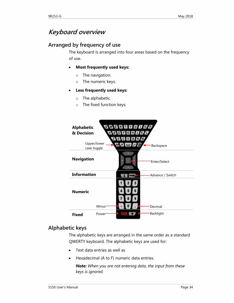
Arranged by frequency of use The keyboard is arranged into four areas based on the frequency of use.
• Most frequently used keys:
o The navigation. o The numeric keys.
• Less frequently used keys:
o The alphabetic. o The fixed function keys.
Alphabetic keys The alphabetic keys are arranged in the same order as a standard QWERTY keyboard. The alphabetic keys are used for:
• Text data entries as well as
• Hexadecimal (A to F) numeric data entries.
Note: When you are not entering data, the input from these keys is ignored.
Backspace
Enter/Select
Advance / Switch
Decimal
Backlight
Upper/lower case toggle
Minus
Power
Alphabetic & Decision
Navigation
Information
Numeric
Fixed
9R253-G May 2018
5150 User’s Manual Page 35
Keyboard functions
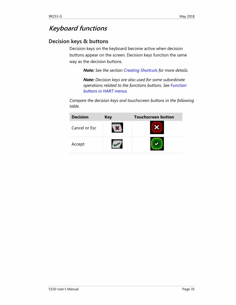
Decision keys & buttons Decision keys on the keyboard become active when decision buttons appear on the screen. Decision keys function the same way as the decision buttons.
Note: See the section Creating Shortcuts for more details.
Note: Decision keys are also used for some subordinate operations related to the functions buttons. See Function buttons in HART menus.
Compare the decision keys and touchscreen buttons in the following table.
Decision Key Touchscreen button
Cancel or Esc
Accept
9R253-G May 2018
5150 User’s Manual Page 36
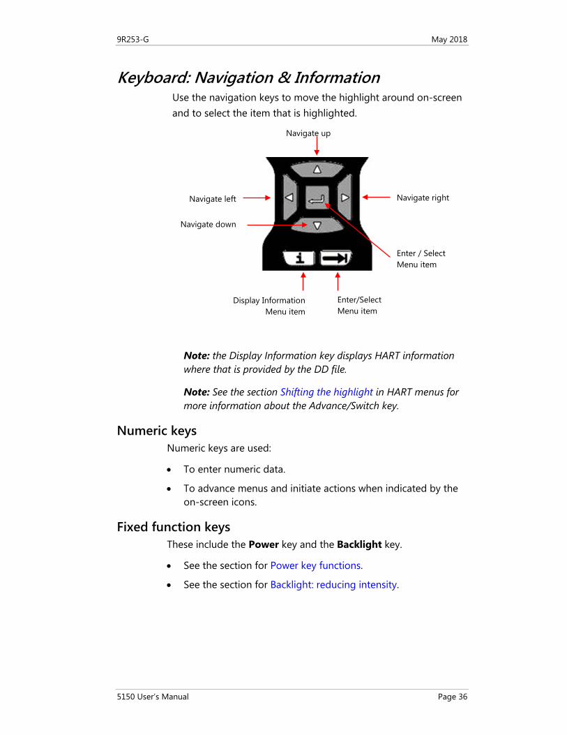
Keyboard: Navigation & Information Use the navigation keys to move the highlight around on-screen and to select the item that is highlighted.
Note: the Display Information key displays HART information where that is provided by the DD file.
Note: See the section Shifting the highlight in HART menus for more information about the Advance/Switch key.
Numeric keys Numeric keys are used:
• To enter numeric data.
• To advance menus and initiate actions when indicated by the on-screen icons.
Fixed function keys These include the Power key and the Backlight key.
• See the section for Power key functions.
• See the section for Backlight: reducing intensity.
Navigate up
Navigate right
Enter / Select Menu item
Enter/Select Menu item
Display Information Menu item
Navigate left
Navigate down
9R253-G May 2018
5150 User’s Manual Page 37
Keyboard: the on-screen keyboard
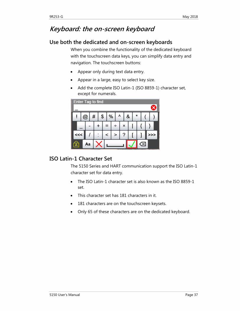
Use both the dedicated and on-screen keyboards When you combine the functionality of the dedicated keyboard with the touchscreen data keys, you can simplify data entry and navigation. The touchscreen buttons:
• Appear only during text data entry.
• Appear in a large, easy to select key size.
• Add the complete ISO Latin-1 (ISO 8859-1) character set, except for numerals.
ISO Latin-1 Character Set The 5150 Series and HART communication support the ISO Latin-1 character set for data entry.
• The ISO Latin-1 character set is also known as the ISO 8859-1 set.
• This character set has 181 characters in it.
• 181 characters are on the touchscreen keysets.
• Only 65 of these characters are on the dedicated keyboard.
9R253-G May 2018
5150 User’s Manual Page 38
181 characters on the touchscreen
All 181 characters are available on the touchscreen.
• The first touch keyset that appears on screen are commonly used symbols. See Diagram of Keyset #1.
• The touch keysets are grouped more logically than the standard order of the ISO Latin-1 Character Set. Additionally, the touch keysets appear in an order based on estimated usage.
• Since the ISO basic Latin alphabet characters are on the dedicated keyboard, they are the last touch keyset. See Touchscreen: Keysets #2–5.
65 characters on the dedicated keyboard
These 65 keys handle most data entry.
• 26 lowercase keys
• 26 uppercase keys
• 1 Caps Lock key
• 10 numeric keys
• 1 minus key
• 1 decimal key
Touchscreen buttons appear
• Whenever a text edit window appears, the touchscreen keyboard becomes visible.
• The touchscreen keysets offer larger buttons than the keyboard for easier typing.
9R253-G May 2018
5150 User’s Manual Page 39
Limited character sets
Buttons and keys are unavailable
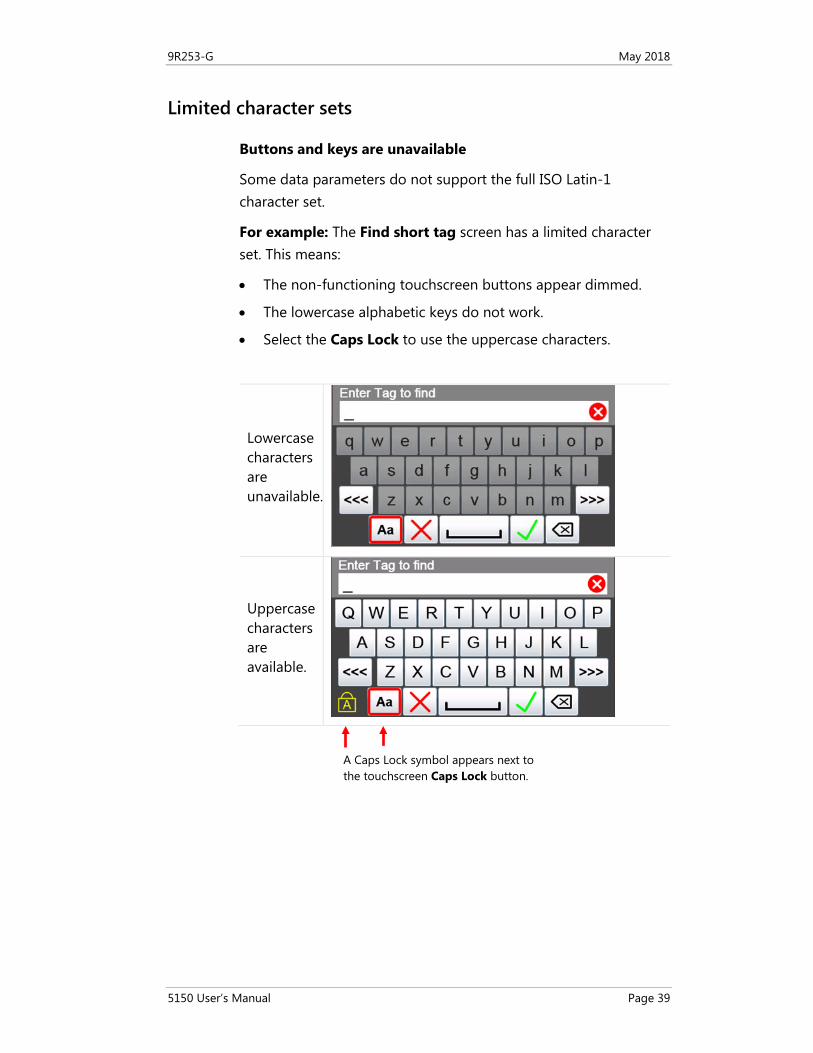
Some data parameters do not support the full ISO Latin-1 character set.
For example: The Find short tag screen has a limited character set. This means:
• The non-functioning touchscreen buttons appear dimmed.
• The lowercase alphabetic keys do not work.
• Select the Caps Lock to use the uppercase characters.
Lowercase characters are unavailable.
Uppercase characters are available.
A Caps Lock symbol appears next to the touchscreen Caps Lock button.
9R253-G May 2018
5150 User’s Manual Page 40
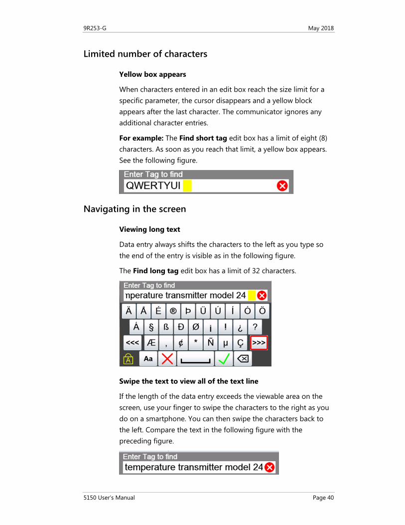
Limited number of characters
Yellow box appears
When characters entered in an edit box reach the size limit for a specific parameter, the cursor disappears and a yellow block appears after the last character. The communicator ignores any additional character entries.
For example: The Find short tag edit box has a limit of eight (8) characters. As soon as you reach that limit, a yellow box appears. See the following figure.
Navigating in the screen
Viewing long text
Data entry always shifts the characters to the left as you type so the end of the entry is visible as in the following figure.
The Find long tag edit box has a limit of 32 characters.
Swipe the text to view all of the text line
If the length of the data entry exceeds the viewable area on the screen, use your finger to swipe the characters to the right as you do on a smartphone. You can then swipe the characters back to the left. Compare the text in the following figure with the preceding figure.
9R253-G May 2018
5150 User’s Manual Page 41
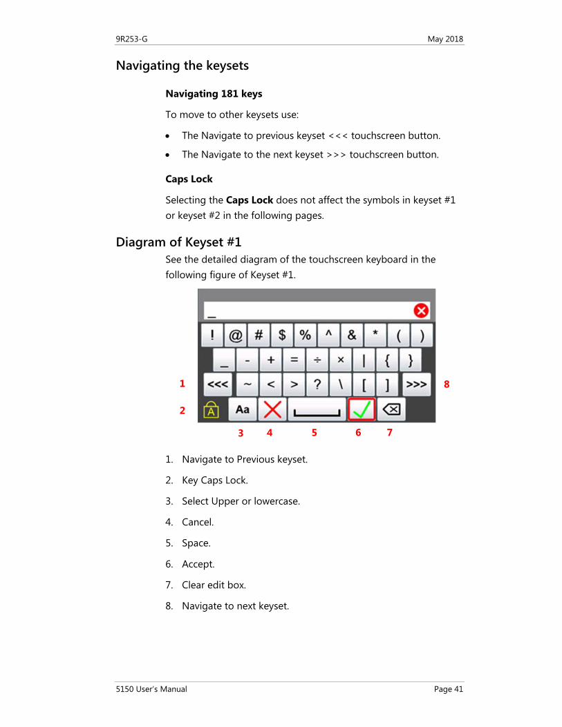
Navigating the keysets
Navigating 181 keys
To move to other keysets use:
• The Navigate to previous keyset <<< touchscreen button.
• The Navigate to the next keyset >>> touchscreen button.
Caps Lock
Selecting the Caps Lock does not affect the symbols in keyset #1 or keyset #2 in the following pages.
Diagram of Keyset #1 See the detailed diagram of the touchscreen keyboard in the following figure of Keyset #1.
1. Navigate to Previous keyset.
2. Key Caps Lock.
3. Select Upper or lowercase.
4. Cancel.
5. Space.
6. Accept.
7. Clear edit box.
8. Navigate to next keyset.
3 4 5 6 7
8 1
2
9R253-G May 2018
5150 User’s Manual Page 42
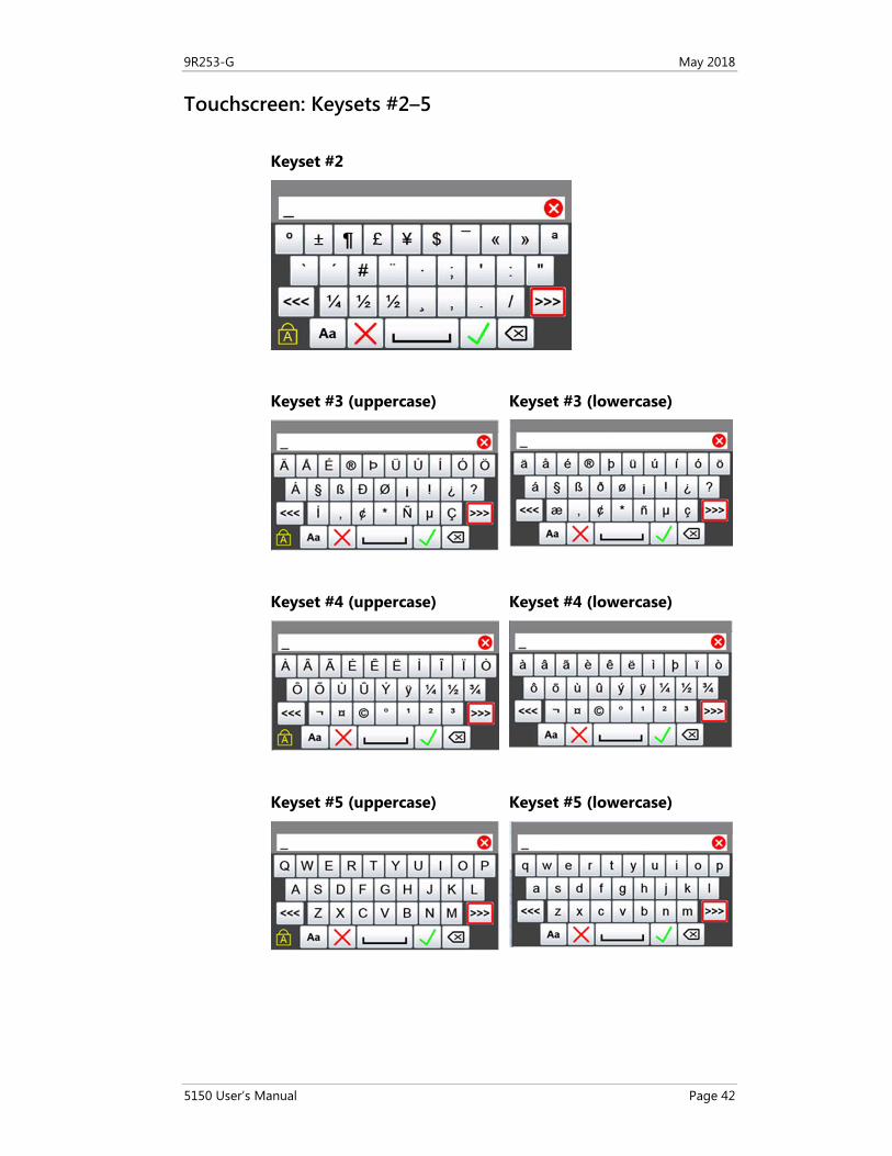
Touchscreen: Keysets #2–5 Keyset #2
Keyset #3 (uppercase)
Keyset #3 (lowercase)
Keyset #4 (uppercase)
Keyset #4 (lowercase)
Keyset #5 (uppercase)
Keyset #5 (lowercase)
9R253-G May 2018
5150 User’s Manual Page 43
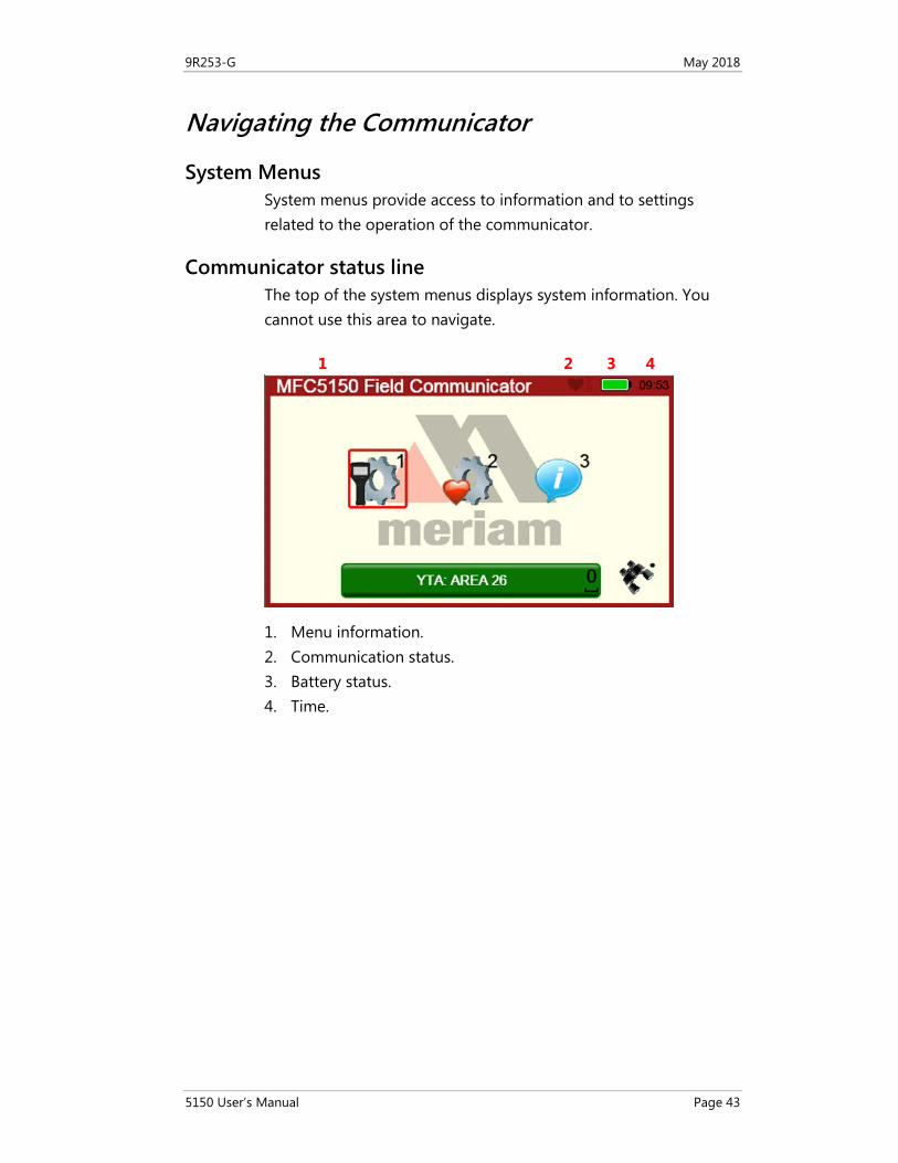
Navigating the Communicator
System Menus System menus provide access to information and to settings related to the operation of the communicator.
Communicator status line The top of the system menus displays system information. You cannot use this area to navigate.
1. Menu information. 2. Communication status. 3. Battery status. 4. Time.
1 2 3 4
9R253-G May 2018
5150 User’s Manual Page 44
Communicator status line explained The following table explains the different parts of the System Menu.
Status line Function
Menu Information
This area displays the system menu. When you see 5150 Field Communicator, you at the top-level menu.
Communication Status
This displays if HART communication is active, whether there is a primary master (host) on the loop, and if there is a burst mode device active.
Battery Status
This gives you a quick reference to the current condition of the battery. There is more information available in System Information.
Current Time The current time is set by you in the Date/Time Setup Menu
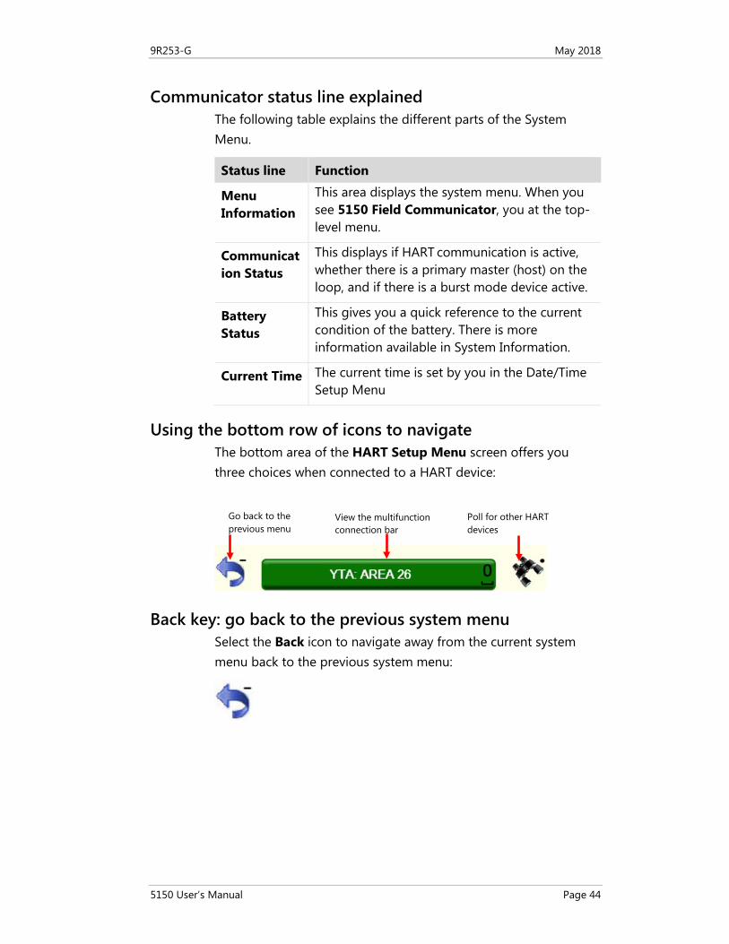
Using the bottom row of icons to navigate The bottom area of the HART Setup Menu screen offers you three choices when connected to a HART device:
Back key: go back to the previous system menu Select the Back icon to navigate away from the current system menu back to the previous system menu:
Poll for other HART devices
View the multifunction connection bar
Go back to the previous menu
9R253-G May 2018
5150 User’s Manual Page 45
HART navigation and connection status
Navigating to the HART Setup Menu From the Main System screen, select the HART Setup icon to see the HART Setup Menu screen displayed in the following section.
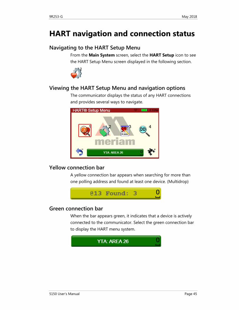
Viewing the HART Setup Menu and navigation options The communicator displays the status of any HART connections and provides several ways to navigate.
Yellow connection bar A yellow connection bar appears when searching for more than one polling address and found at least one device. (Multidrop)
Green connection bar When the bar appears green, it indicates that a device is actively connected to the communicator. Select the green connection bar to display the HART menu system.
9R253-G May 2018
5150 User’s Manual Page 46
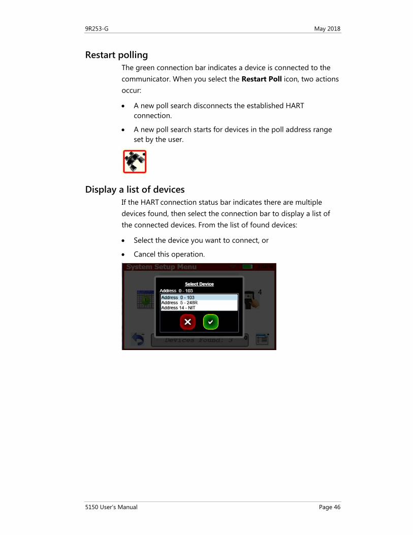
Restart polling The green connection bar indicates a device is connected to the communicator. When you select the Restart Poll icon, two actions occur:
• A new poll search disconnects the established HART connection.
• A new poll search starts for devices in the poll address range set by the user.
Display a list of devices If the HART connection status bar indicates there are multiple devices found, then select the connection bar to display a list of the connected devices. From the list of found devices:
• Select the device you want to connect, or
• Cancel this operation.
9R253-G May 2018
5150 User’s Manual Page 47
Main system menus
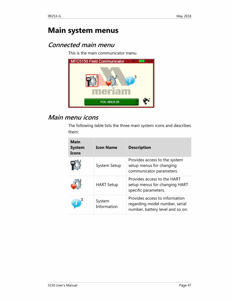
Connected main menu This is the main communicator menu.
Main menu icons The following table lists the three main system icons and describes them:
Main System Icons
Icon Name Description
System Setup
Provides access to the system setup menus for changing communicator parameters.
HART Setup
Provides access to the HART
setup menus for changing HART
specific parameters.
System Information
Provides access to information regarding model number, serial number, battery level and so on.
9R253-G May 2018
5150 User’s Manual Page 48
System Setup Menu
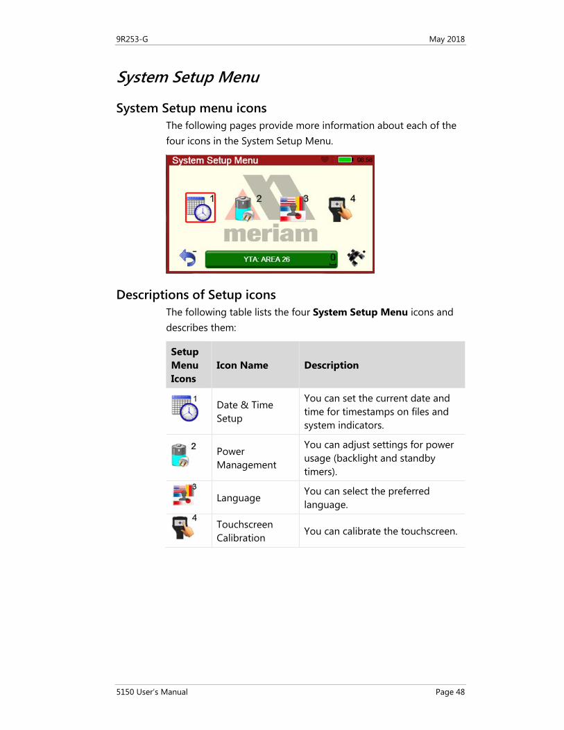
System Setup menu icons The following pages provide more information about each of the four icons in the System Setup Menu.
Descriptions of Setup icons The following table lists the four System Setup Menu icons and describes them:
Setup Menu Icons
Icon Name Description
Date & Time Setup
You can set the current date and time for timestamps on files and system indicators.
Power Management
You can adjust settings for power usage (backlight and standby timers).
Language You can select the preferred language.
Touchscreen Calibration
You can calibrate the touchscreen.
9R253-G May 2018
5150 User’s Manual Page 49
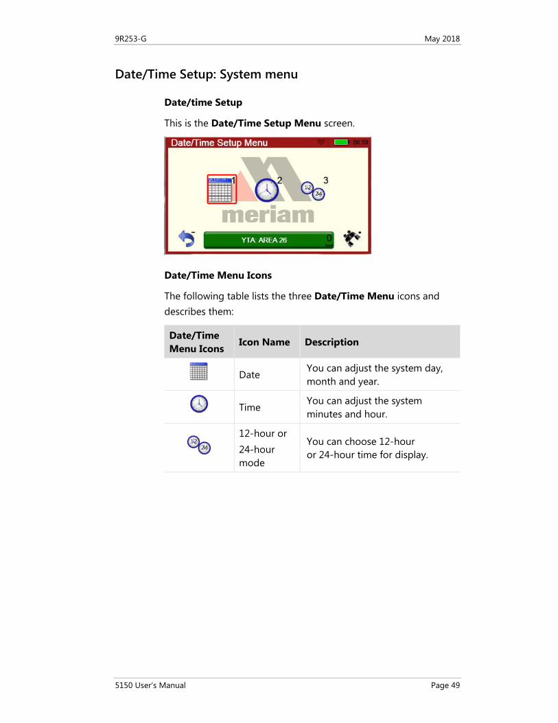
Date/Time Setup: System menu
Date/time Setup
This is the Date/Time Setup Menu screen.
Date/Time Menu Icons
The following table lists the three Date/Time Menu icons and describes them:
Date/Time Menu Icons
Icon Name Description
Date You can adjust the system day, month and year.
Time You can adjust the system minutes and hour.
12-hour or 24-hour mode
You can choose 12-hour or 24-hour time for display.
9R253-G May 2018
5150 User’s Manual Page 50
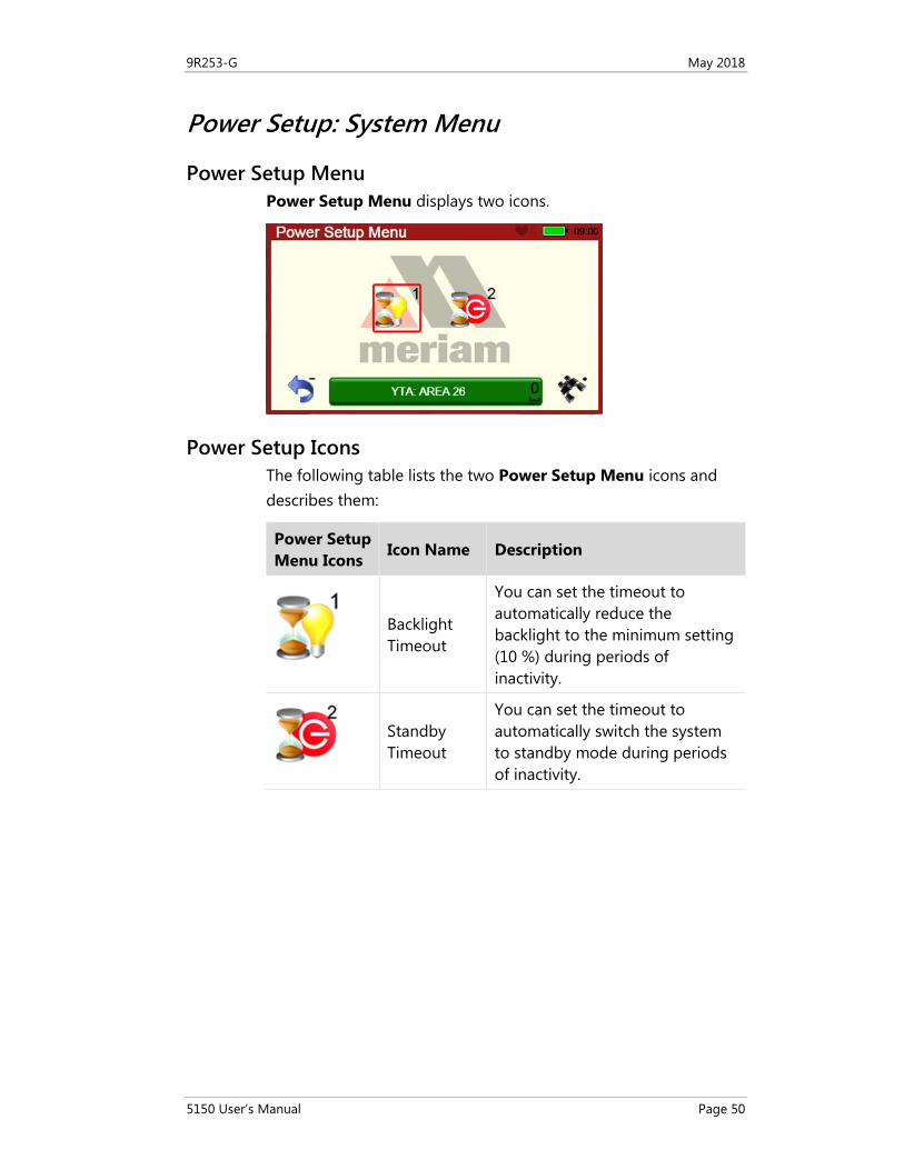
Power Setup: System Menu
Power Setup Menu Power Setup Menu displays two icons.
Power Setup Icons The following table lists the two Power Setup Menu icons and describes them:
Power Setup Menu Icons
Icon Name Description
Backlight Timeout
You can set the timeout to automatically reduce the backlight to the minimum setting (10 %) during periods of inactivity.
Standby Timeout
You can set the timeout to automatically switch the system to standby mode during periods of inactivity.
9R253-G May 2018
5150 User’s Manual Page 51
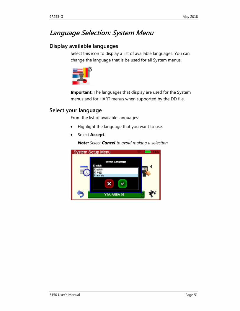
Language Selection: System Menu
Display available languages Select this icon to display a list of available languages. You can change the language that is be used for all System menus.
Important: The languages that display are used for the System menus and for HART menus when supported by the DD file.
Select your language From the list of available languages:
• Highlight the language that you want to use.
• Select Accept.
Note: Select Cancel to avoid making a selection
9R253-G May 2018
5150 User’s Manual Page 52
Language Selection: Displayed
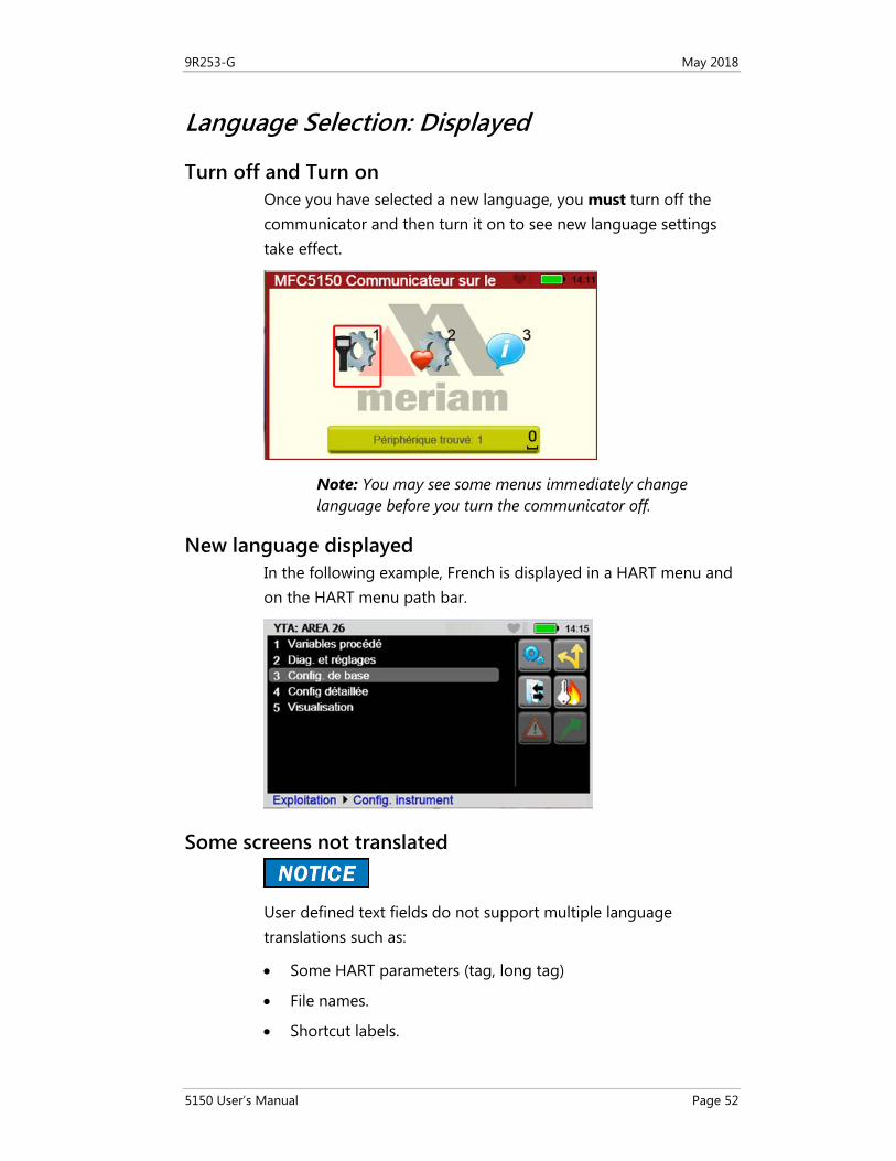
Turn off and Turn on Once you have selected a new language, you must turn off the communicator and then turn it on to see new language settings take effect.
Note: You may see some menus immediately change language before you turn the communicator off.
New language displayed In the following example, French is displayed in a HART menu and on the HART menu path bar.
Some screens not translated
User defined text fields do not support multiple language translations such as:
• Some HART parameters (tag, long tag)
• File names.
• Shortcut labels.
9R253-G May 2018
5150 User’s Manual Page 53
Calibrating the touchscreen: System Menu
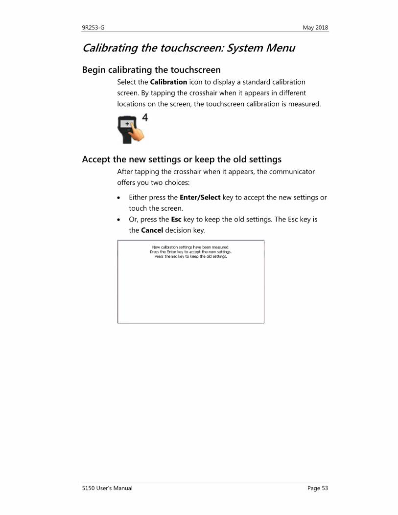
Begin calibrating the touchscreen Select the Calibration icon to display a standard calibration screen. By tapping the crosshair when it appears in different locations on the screen, the touchscreen calibration is measured.
Accept the new settings or keep the old settings After tapping the crosshair when it appears, the communicator offers you two choices:
• Either press the Enter/Select key to accept the new settings or touch the screen.
• Or, press the Esc key to keep the old settings. The Esc key is the Cancel decision key.
9R253-G May 2018
5150 User’s Manual Page 54
System Information: System Menu
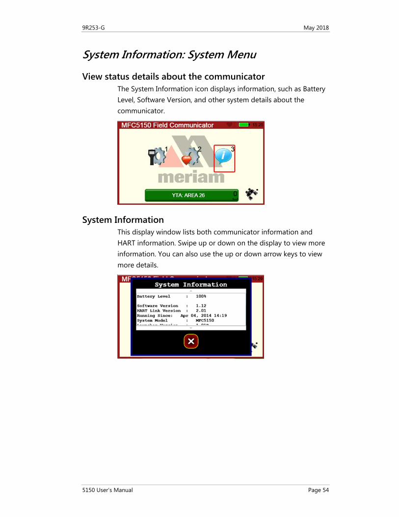
View status details about the communicator The System Information icon displays information, such as Battery Level, Software Version, and other system details about the communicator.
System Information This display window lists both communicator information and HART information. Swipe up or down on the display to view more information. You can also use the up or down arrow keys to view more details.
9R253-G May 2018
5150 User’s Manual Page 55
HART Setup Menu
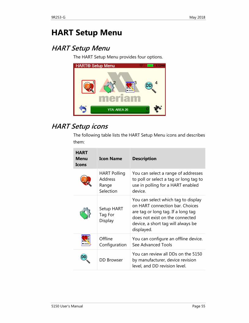
HART Setup Menu The HART Setup Menu provides four options.
HART Setup icons The following table lists the HART Setup Menu icons and describes them:
HART Menu Icons
Icon Name Description
HART Polling Address Range Selection
You can select a range of addresses to poll or select a tag or long tag to use in polling for a HART enabled device.
Setup HART Tag For Display
You can select which tag to display on HART connection bar. Choices are tag or long tag. If a long tag does not exist on the connected device, a short tag will always be displayed.
Offline Configuration
You can configure an offline device. See Advanced Tools
DD Browser You can review all DDs on the 5150 by manufacturer, device revision level, and DD revision level.
9R253-G May 2018
5150 User’s Manual Page 56
Shifting the highlight in HART menus
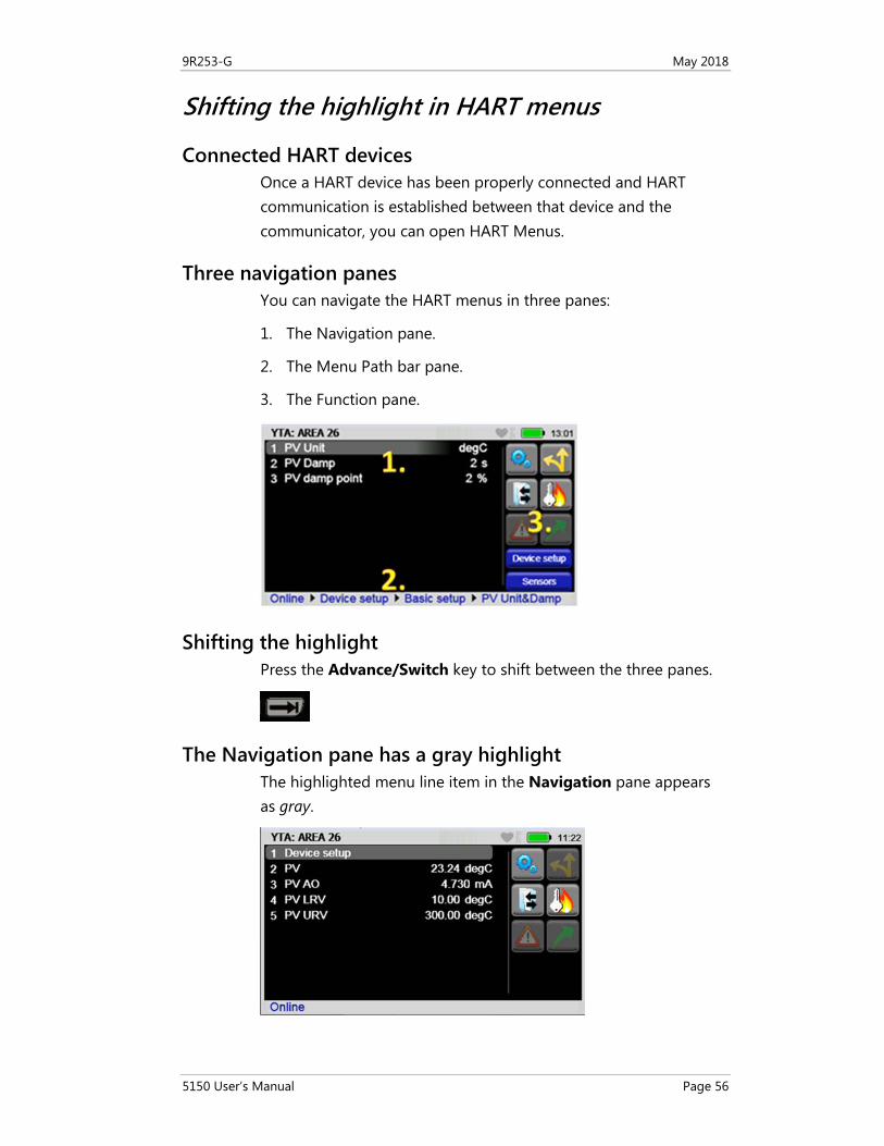
Connected HART devices Once a HART device has been properly connected and HART communication is established between that device and the communicator, you can open HART Menus.
Three navigation panes You can navigate the HART menus in three panes:
1. The Navigation pane.
2. The Menu Path bar pane.
3. The Function pane.
Shifting the highlight Press the Advance/Switch key to shift between the three panes.
The Navigation pane has a gray highlight The highlighted menu line item in the Navigation pane appears as gray.
9R253-G May 2018
5150 User’s Manual Page 57
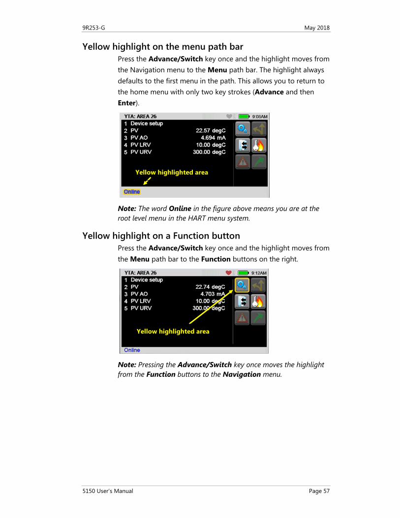
Yellow highlight on the menu path bar Press the Advance/Switch key once and the highlight moves from the Navigation menu to the Menu path bar. The highlight always defaults to the first menu in the path. This allows you to return to the home menu with only two key strokes (Advance and then Enter).
Note: The word Online in the figure above means you are at the root level menu in the HART menu system.
Yellow highlight on a Function button Press the Advance/Switch key once and the highlight moves from the Menu path bar to the Function buttons on the right.
Note: Pressing the Advance/Switch key once moves the highlight from the Function buttons to the Navigation menu.
Yellow highlighted area
Yellow highlighted area
9R253-G May 2018
5150 User’s Manual Page 58
Status Line for the connecting device
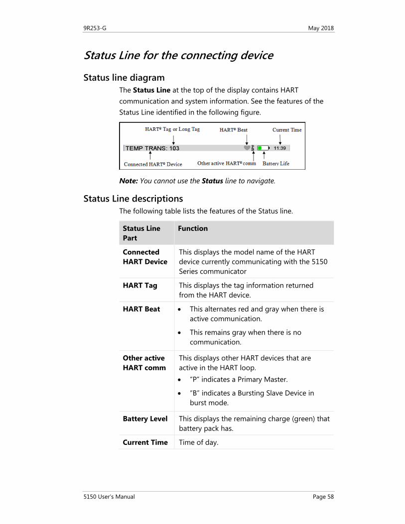
Status line diagram The Status Line at the top of the display contains HART communication and system information. See the features of the Status Line identified in the following figure.
Note: You cannot use the Status line to navigate.
Status Line descriptions The following table lists the features of the Status line.
Status Line Part
Function
Connected HART Device
This displays the model name of the HART device currently communicating with the 5150 Series communicator
HART Tag This displays the tag information returned from the HART device.
HART Beat • This alternates red and gray when there is active communication.
• This remains gray when there is no communication.
Other active HART comm
This displays other HART devices that are active in the HART loop. • “P” indicates a Primary Master.
• “B” indicates a Bursting Slave Device in burst mode.
Battery Level This displays the remaining charge (green) that battery pack has.
Current Time Time of day.
9R253-G May 2018
5150 User’s Manual Page 59
DD files control HART menus
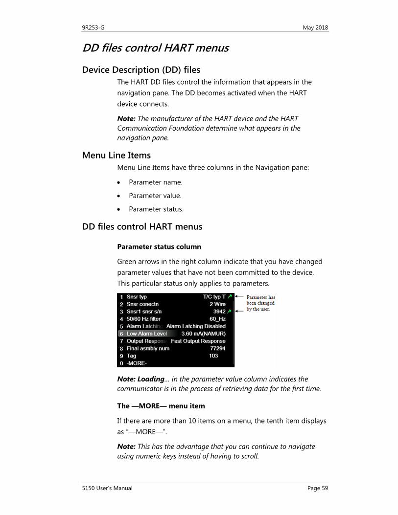
Device Description (DD) files The HART DD files control the information that appears in the navigation pane. The DD becomes activated when the HART device connects.
Note: The manufacturer of the HART device and the HART Communication Foundation determine what appears in the navigation pane.
Menu Line Items Menu Line Items have three columns in the Navigation pane:
• Parameter name.
• Parameter value.
• Parameter status.
DD files control HART menus
Parameter status column
Green arrows in the right column indicate that you have changed parameter values that have not been committed to the device. This particular status only applies to parameters.
Note: Loading… in the parameter value column indicates the communicator is in the process of retrieving data for the first time.
The —MORE— menu item
If there are more than 10 items on a menu, the tenth item displays as “—MORE—”.
Note: This has the advantage that you can continue to navigate using numeric keys instead of having to scroll.
9R253-G May 2018
5150 User’s Manual Page 60
Function buttons in HART menus
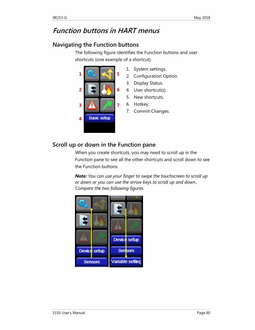
Navigating the Function buttons The following figure identifies the Function buttons and user shortcuts (one example of a shortcut).
1. System settings. 2. Configuration Option. 3. Display Status. 4. User shortcut(s). 5. New shortcuts. 6. Hotkey. 7. Commit Changes.
Scroll up or down in the Function pane When you create shortcuts, you may need to scroll up in the Function pane to see all the other shortcuts and scroll down to see the Function buttons.
Note: You can use your finger to swipe the touchscreen to scroll up or down or you can use the arrow keys to scroll up and down.. Compare the two following figures.
1
2
3
4
5
6
7
9R253-G May 2018
5150 User’s Manual Page 61
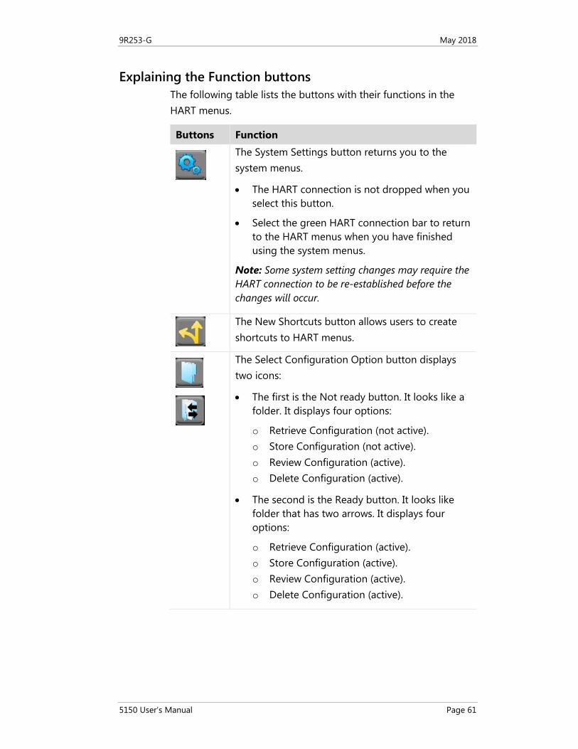
Explaining the Function buttons The following table lists the buttons with their functions in the HART menus.
Buttons Function
The System Settings button returns you to the system menus.
• The HART connection is not dropped when you select this button.
• Select the green HART connection bar to return to the HART menus when you have finished using the system menus.
Note: Some system setting changes may require the HART connection to be re-established before the changes will occur.
The New Shortcuts button allows users to create shortcuts to HART menus.
The Select Configuration Option button displays two icons:
• The first is the Not ready button. It looks like a folder. It displays four options:
o Retrieve Configuration (not active). o Store Configuration (not active). o Review Configuration (active). o Delete Configuration (active).
• The second is the Ready button. It looks like folder that has two arrows. It displays four options:
o Retrieve Configuration (active). o Store Configuration (active). o Review Configuration (active). o Delete Configuration (active).
9R253-G May 2018
5150 User’s Manual Page 62
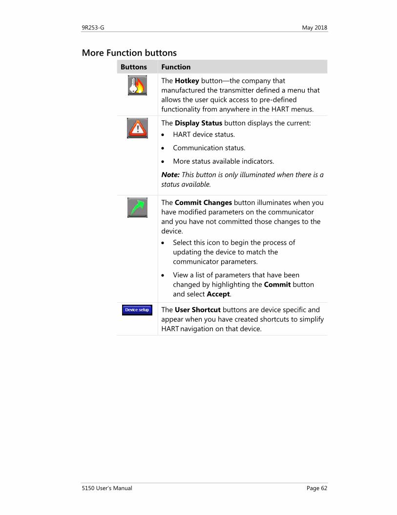
More Function buttons Buttons Function
The Hotkey button—the company that manufactured the transmitter defined a menu that allows the user quick access to pre-defined functionality from anywhere in the HART menus.
The Display Status button displays the current: • HART device status.
• Communication status.
• More status available indicators.
Note: This button is only illuminated when there is a status available.
The Commit Changes button illuminates when you have modified parameters on the communicator and you have not committed those changes to the device. • Select this icon to begin the process of
updating the device to match the communicator parameters.
• View a list of parameters that have been changed by highlighting the Commit button and select Accept.
The User Shortcut buttons are device specific and appear when you have created shortcuts to simplify HART navigation on that device.
9R253-G May 2018
5150 User’s Manual Page 63
Creating Shortcuts
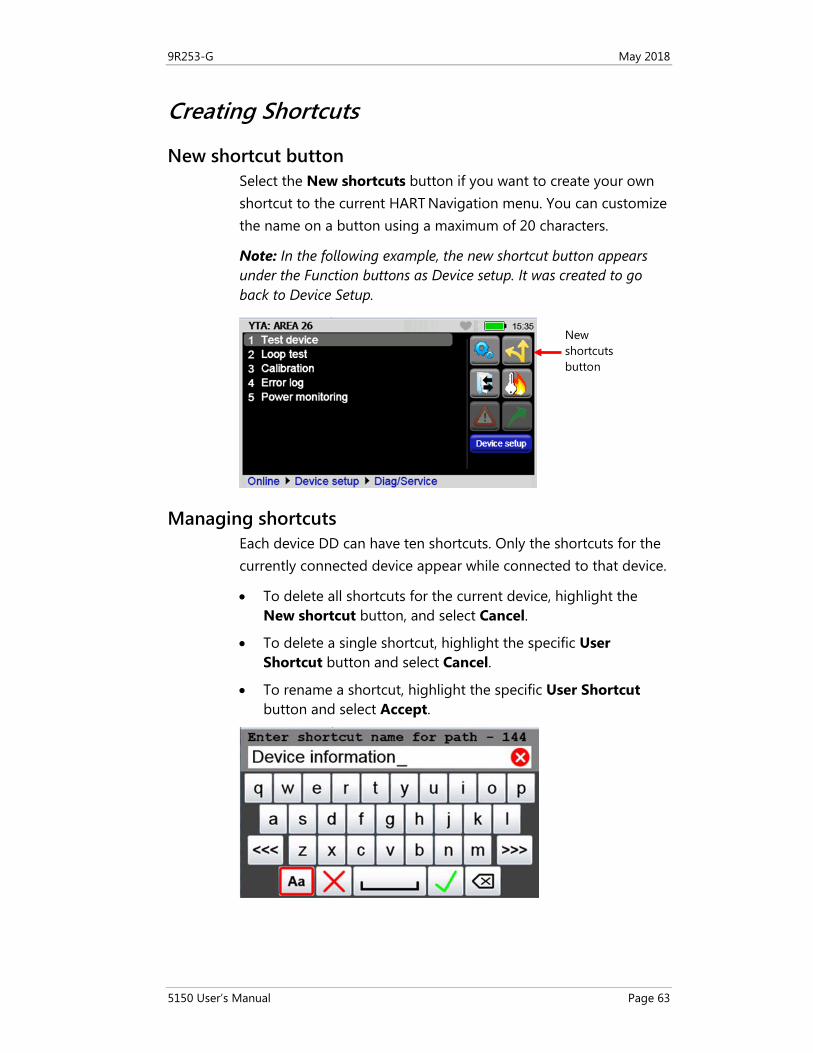
New shortcut button Select the New shortcuts button if you want to create your own shortcut to the current HART Navigation menu. You can customize the name on a button using a maximum of 20 characters.
Note: In the following example, the new shortcut button appears under the Function buttons as Device setup. It was created to go back to Device Setup.
Managing shortcuts Each device DD can have ten shortcuts. Only the shortcuts for the currently connected device appear while connected to that device.
• To delete all shortcuts for the current device, highlight the New shortcut button, and select Cancel.
• To delete a single shortcut, highlight the specific User Shortcut button and select Cancel.
• To rename a shortcut, highlight the specific User Shortcut button and select Accept.
New shortcuts button
9R253-G May 2018
5150 User’s Manual Page 64
Invalid shortcuts
It is invalid to create a shortcut on the Online menu (often called the Root menu).
HART menu path bar
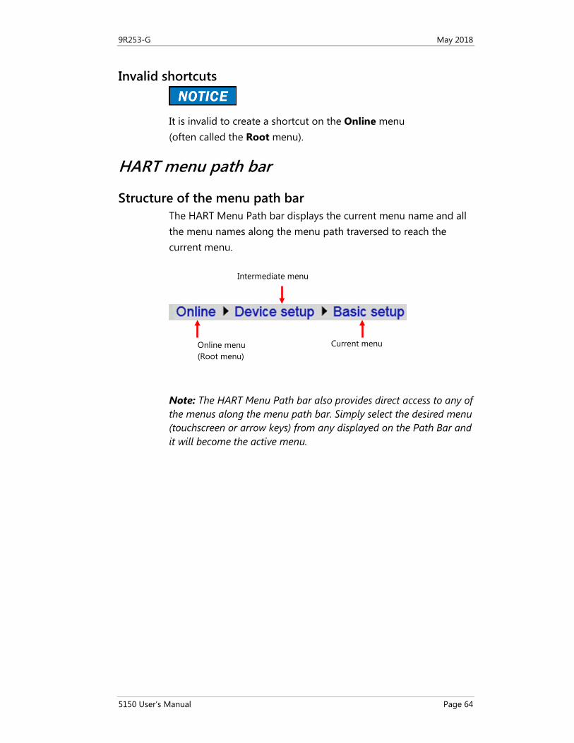
Structure of the menu path bar The HART Menu Path bar displays the current menu name and all the menu names along the menu path traversed to reach the current menu.
Note: The HART Menu Path bar also provides direct access to any of the menus along the menu path bar. Simply select the desired menu (touchscreen or arrow keys) from any displayed on the Path Bar and it will become the active menu.
Online menu (Root menu)
Intermediate menu
Current menu
9R253-G May 2018
5150 User’s Manual Page 65
Advanced Tools for HART
DD Browser and Offline Configuration The 5150 provides you with two advanced options:
1. DD Browser: Use this button to review all the DDs on the 5150.
2. Offline Configuration: Use this button to:
a. Create new configurations.
b. Modify existing configurations.
Note: To use both functions you can navigate the three levels.
a. Manufacturer (first level).
b. Device name (second level).
c. Device revision number (third level).
DD Browser
Three ways to navigate in the DD Browser Select the DD Browser button to navigate the levels.
Three ways to navigate through the lists in each level:
1. Select the up or down arrow keys.
2. Type one or more letters of the manufacturer’s name or device name.
3. Tap the touchscreen to select a name or device.
9R253-G May 2018
5150 User’s Manual Page 66
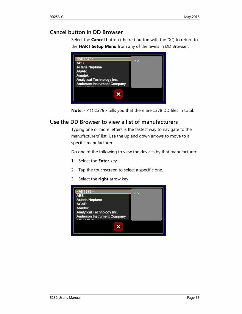
Cancel button in DD Browser Select the Cancel button (the red button with the “X”) to return to the HART Setup Menu from any of the levels in DD Browser.
Note: <ALL 1378> tells you that there are 1378 DD files in total.
Use the DD Browser to view a list of manufacturers Typing one or more letters is the fastest way to navigate to the manufacturers’ list. Use the up and down arrows to move to a specific manufacturer.
Do one of the following to view the devices by that manufacturer:
1. Select the Enter key.
2. Tap the touchscreen to select a specific one.
3. Select the right arrow key.
9R253-G May 2018
5150 User’s Manual Page 67
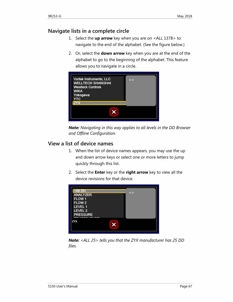
Navigate lists in a complete circle 1. Select the up arrow key when you are on <ALL 1378> to
navigate to the end of the alphabet. (See the figure below.)
2. Or, select the down arrow key when you are at the end of the alphabet to go to the beginning of the alphabet. This feature allows you to navigate in a circle.
Note: Navigating in this way applies to all levels in the DD Browser and Offline Configuration.
View a list of device names 1. When the list of device names appears, you may use the up
and down arrow keys or select one or more letters to jump quickly through this list.
2. Select the Enter key or the right arrow key to view all the device revisions for that device.
Note: <ALL 25> tells you that the ZYX manufacturer has 25 DD files.
9R253-G May 2018
5150 User’s Manual Page 68
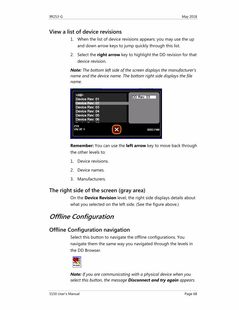
View a list of device revisions 1. When the list of device revisions appears: you may use the up
and down arrow keys to jump quickly through this list.
2. Select the right arrow key to highlight the DD revision for that device revision.
Note: The bottom left side of the screen displays the manufacturer’s name and the device name. The bottom right side displays the file name.
Remember: You can use the left arrow key to move back through the other levels to:
1. Device revisions.
2. Device names.
3. Manufacturers.
The right side of the screen (gray area) On the Device Revision level, the right side displays details about what you selected on the left side. (See the figure above.)
Offline Configuration
Offline Configuration navigation Select this button to navigate the offline configurations. You navigate them the same way you navigated through the levels in the DD Browser.
Note: If you are communicating with a physical device when you select this button, the message Disconnect and try again appears.
9R253-G May 2018
5150 User’s Manual Page 69
Two ways to use the offline configuration After selecting the Offline Configuration button, you can:
1. Create a new configuration from:
a. A <BLANK> configuration.
b. An existing configuration on the 5150 and store it with a new name.
2. Edit an existing configuration.
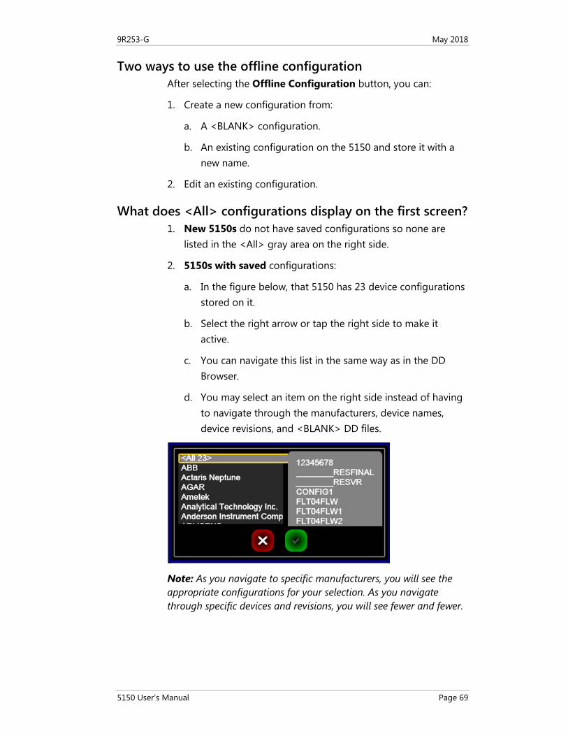
What does <All> configurations display on the first screen? 1. New 5150s do not have saved configurations so none are
listed in the <All> gray area on the right side.
2. 5150s with saved configurations:
a. In the figure below, that 5150 has 23 device configurations stored on it.
b. Select the right arrow or tap the right side to make it active.
c. You can navigate this list in the same way as in the DD Browser.
d. You may select an item on the right side instead of having to navigate through the manufacturers, device names, device revisions, and <BLANK> DD files.
Note: As you navigate to specific manufacturers, you will see the appropriate configurations for your selection. As you navigate through specific devices and revisions, you will see fewer and fewer.
9R253-G May 2018
5150 User’s Manual Page 70
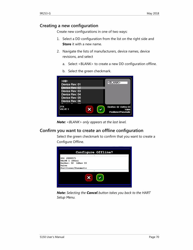
Creating a new configuration Create new configurations in one of two ways:
1. Select a DD configuration from the list on the right side and Store it with a new name.
2. Navigate the lists of manufacturers, device names, device revisions, and select
a. Select <BLANK> to create a new DD configuration offline.
b. Select the green checkmark.
Note: <BLANK> only appears at the last level.
Confirm you want to create an offline configuration Select the green checkmark to confirm that you want to create a Configure Offline.
Note: Selecting the Cancel button takes you back to the HART Setup Menu.
9R253-G May 2018
5150 User’s Manual Page 71
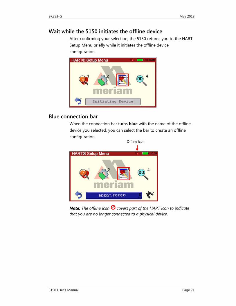
Wait while the 5150 initiates the offline device After confirming your selection, the 5150 returns you to the HART Setup Menu briefly while it initiates the offline device configuration.
Blue connection bar When the connection bar turns blue with the name of the offline device you selected, you can select the bar to create an offline configuration.
Note: The offline icon covers part of the HART icon to indicate that you are no longer connected to a physical device.
Offline icon
9R253-G May 2018
5150 User’s Manual Page 72
Indicators in Offline Configuration
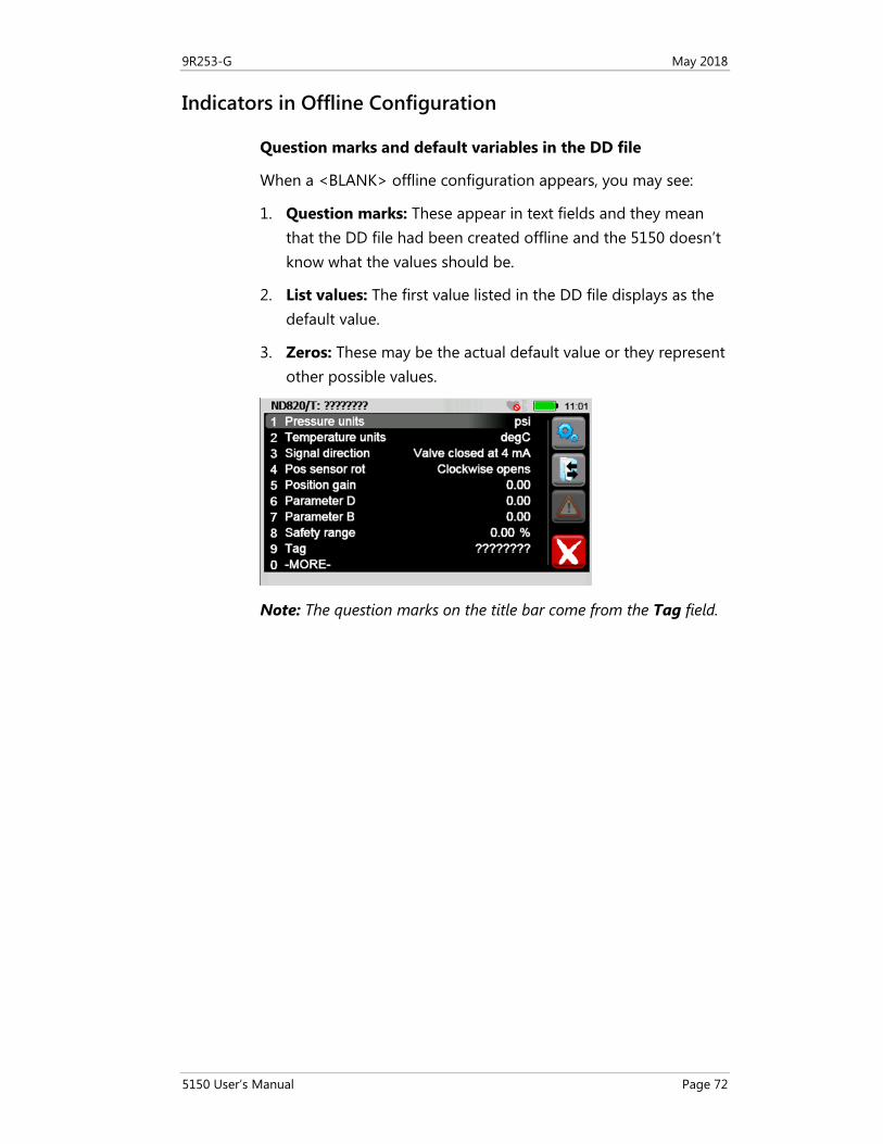
Question marks and default variables in the DD file
When a <BLANK> offline configuration appears, you may see:
1. Question marks: These appear in text fields and they mean that the DD file had been created offline and the 5150 doesn’t know what the values should be.
2. List values: The first value listed in the DD file displays as the default value.
3. Zeros: These may be the actual default value or they represent other possible values.
Note: The question marks on the title bar come from the Tag field.
9R253-G May 2018
5150 User’s Manual Page 73
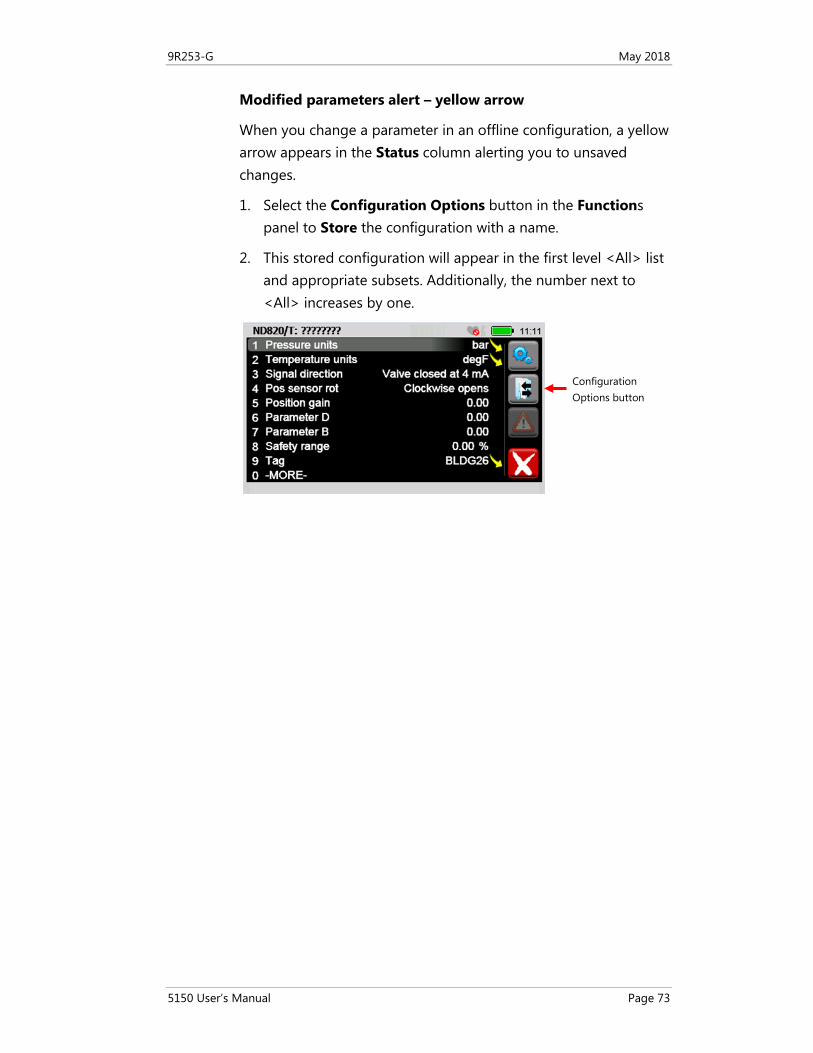
Modified parameters alert – yellow arrow
When you change a parameter in an offline configuration, a yellow arrow appears in the Status column alerting you to unsaved changes.
1. Select the Configuration Options button in the Functions panel to Store the configuration with a name.
2. This stored configuration will appear in the first level <All> list and appropriate subsets. Additionally, the number next to <All> increases by one.
Configuration Options button
9R253-G May 2018
5150 User’s Manual Page 74
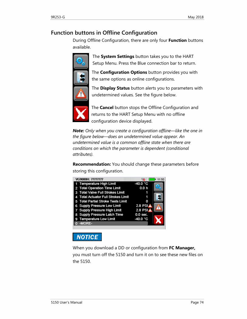
Function buttons in Offline Configuration During Offline Configuration, there are only four Function buttons available.
Note: Only when you create a configuration offline—like the one in the figure below—does an undetermined value appear. An undetermined value is a common offline state when there are conditions on which the parameter is dependent (conditional attributes).
Recommendation: You should change these parameters before storing this configuration.
When you download a DD or configuration from FC Manager, you must turn off the 5150 and turn it on to see these new files on the 5150.
The Cancel button stops the Offline Configuration and returns to the HART Setup Menu with no offline configuration device displayed.
The System Settings button takes you to the HART Setup Menu. Press the Blue connection bar to return.
The Display Status button alerts you to parameters with undetermined values. See the figure below.
The Configuration Options button provides you with the same options as online configurations.
9R253-G May 2018
5150 User’s Manual Page 75
HART Communication with the 5150 Series
Maintain field devices The communicator provides device specific HART communication functions that allow the user
• To poll.
• To commission devices.
• To configure or re-configure.
• To maintain supported HART field devices.
• To maintain devices through analog and sensor trim adjustments.
HART commands To facilitate communication with a HART field device the communicator uses the following commands:
• Universal.
• Common Practice.
• Device Specific.
Device Description file (DD) uses • Many other features defined by the device manufacturer are
also supported.
• The communicator will communicate with any HART device through Universal and Common Practice Commands using the standard Generic DD but must have the DD for a specific HART device installed before it can execute Device Specific Commands.
• When HART device support for new devices becomes available, the communicator software can be easily updated using a computer with an internet connection and software provided.
Updating your communicator with DDs See the section for Updating communicator software for more information and links about DD files.
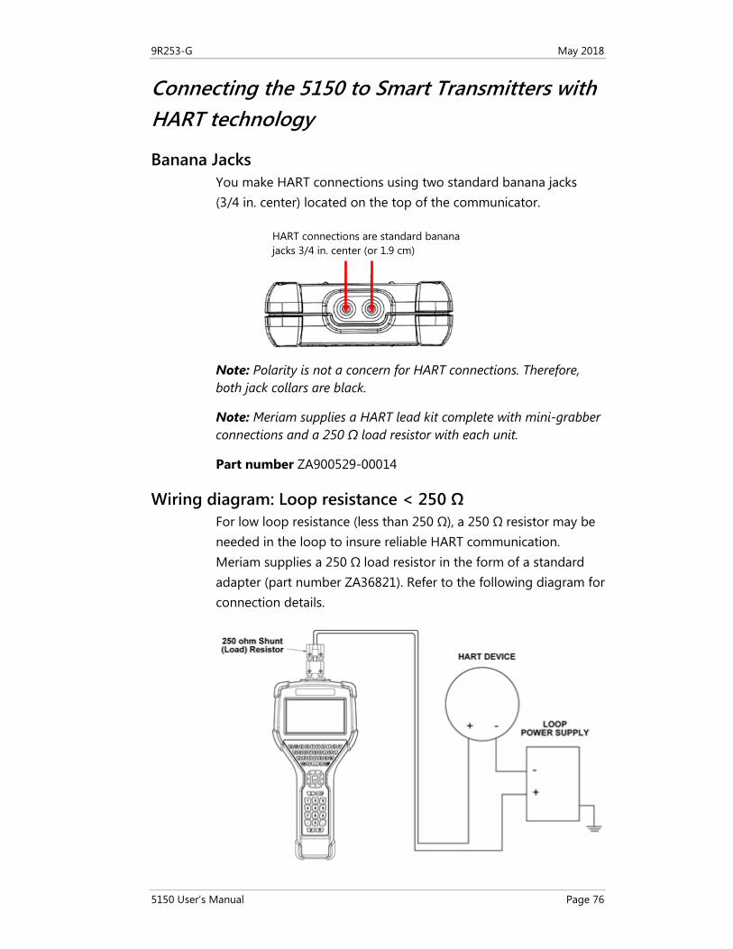
9R253-G May 2018
5150 User’s Manual Page 76
Connecting the 5150 to Smart Transmitters with HART technology
Banana Jacks You make HART connections using two standard banana jacks (3/4 in. center) located on the top of the communicator.
Note: Polarity is not a concern for HART connections. Therefore, both jack collars are black.
Note: Meriam supplies a HART lead kit complete with mini-grabber connections and a 250 Ω load resistor with each unit.
Part number ZA900529-00014
Wiring diagram: Loop resistance < 250 Ω For low loop resistance (less than 250 Ω), a 250 Ω resistor may be needed in the loop to insure reliable HART communication. Meriam supplies a 250 Ω load resistor in the form of a standard adapter (part number ZA36821). Refer to the following diagram for connection details.
HART connections are standard banana jacks 3/4 in. center (or 1.9 cm)
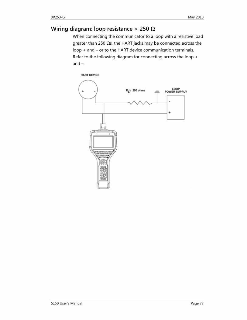
9R253-G May 2018
5150 User’s Manual Page 77
Wiring diagram: loop resistance > 250 Ω When connecting the communicator to a loop with a resistive load greater than 250 Ωs, the HART jacks may be connected across the loop + and – or to the HART device communication terminals. Refer to the following diagram for connecting across the loop + and –.
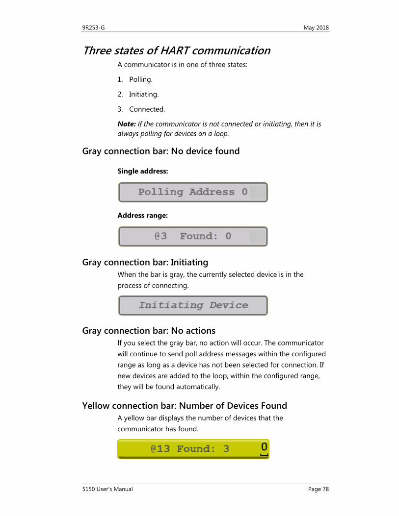
9R253-G May 2018
5150 User’s Manual Page 78
Three states of HART communication A communicator is in one of three states:
1. Polling.
2. Initiating.
3. Connected.
Note: If the communicator is not connected or initiating, then it is always polling for devices on a loop.
Gray connection bar: No device found
Single address:
Address range:
Gray connection bar: Initiating When the bar is gray, the currently selected device is in the process of connecting.
Gray connection bar: No actions If you select the gray bar, no action will occur. The communicator will continue to send poll address messages within the configured range as long as a device has not been selected for connection. If new devices are added to the loop, within the configured range, they will be found automatically.
Yellow connection bar: Number of Devices Found A yellow bar displays the number of devices that the communicator has found.
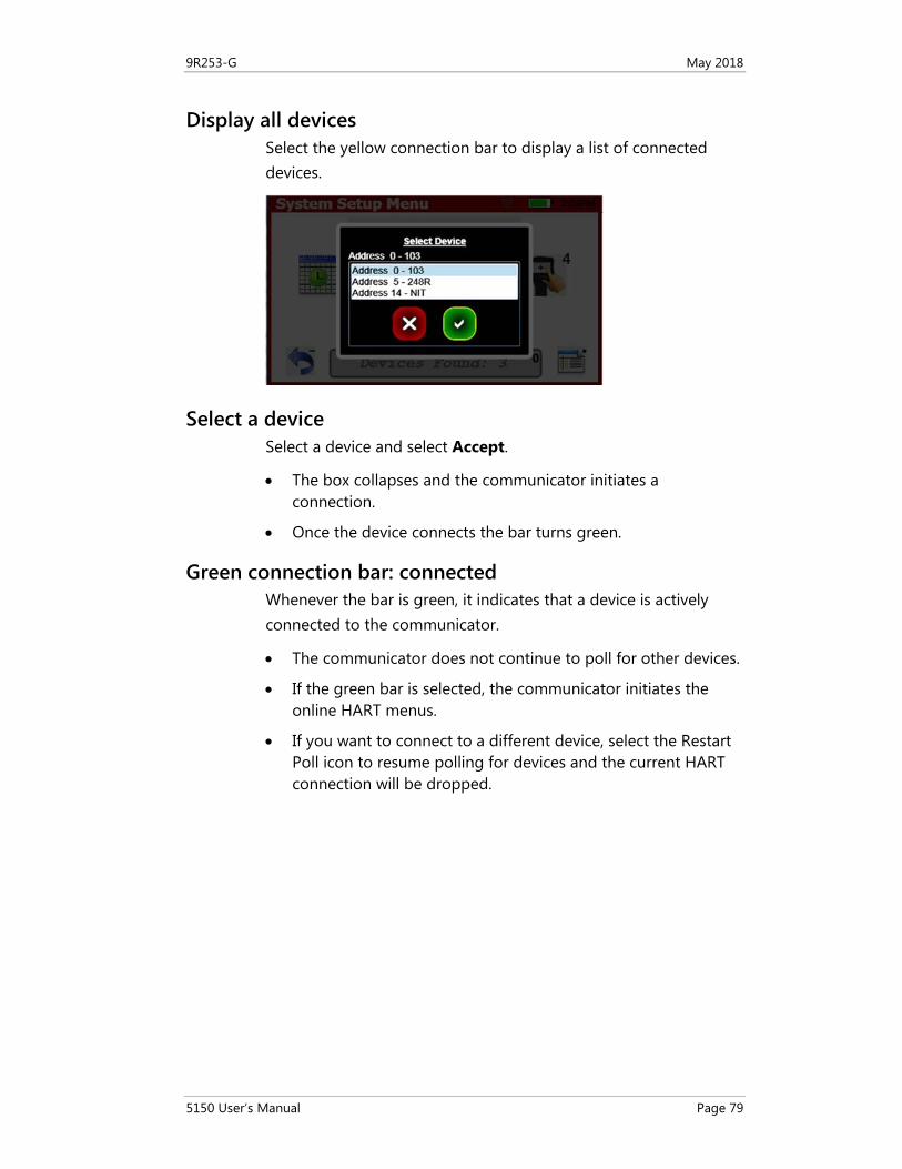
9R253-G May 2018
5150 User’s Manual Page 79
Display all devices Select the yellow connection bar to display a list of connected devices.
Select a device Select a device and select Accept.
• The box collapses and the communicator initiates a connection.
• Once the device connects the bar turns green.
Green connection bar: connected Whenever the bar is green, it indicates that a device is actively connected to the communicator.
• The communicator does not continue to poll for other devices.
• If the green bar is selected, the communicator initiates the online HART menus.
• If you want to connect to a different device, select the Restart Poll icon to resume polling for devices and the current HART connection will be dropped.
9R253-G May 2018
5150 User’s Manual Page 80
Specific and Generic HART communication
Find specific devices The communicator supports a large and growing number of Device Specific DDs (Device Definition files).
Find generic devices The communicator includes Generic HART Communication capability to communicate with HART devices that are not yet supported with Device Specific DD files or that do not require DD files.
• Generic communication allows you to communicate with any HART device using Universal and Common Practice commands to poll, configure, and maintain HART devices.
• Specific functions supported include most polling, tagging, device configuration and trim operations for analog outputs.
• Generic communications do not support Device Specific commands for higher order HART functions.
• Review the User’s Manual for the HART device of interest for more information on device specific command support.
Generic starts automatically The Generic HART Communication mode starts automatically when HART communication is initiated with a device for which no Device Specific DD (device object file) is stored in the communicator’s flash memory. When this occurs, the status line displays:
• Generic.
• The device tag.
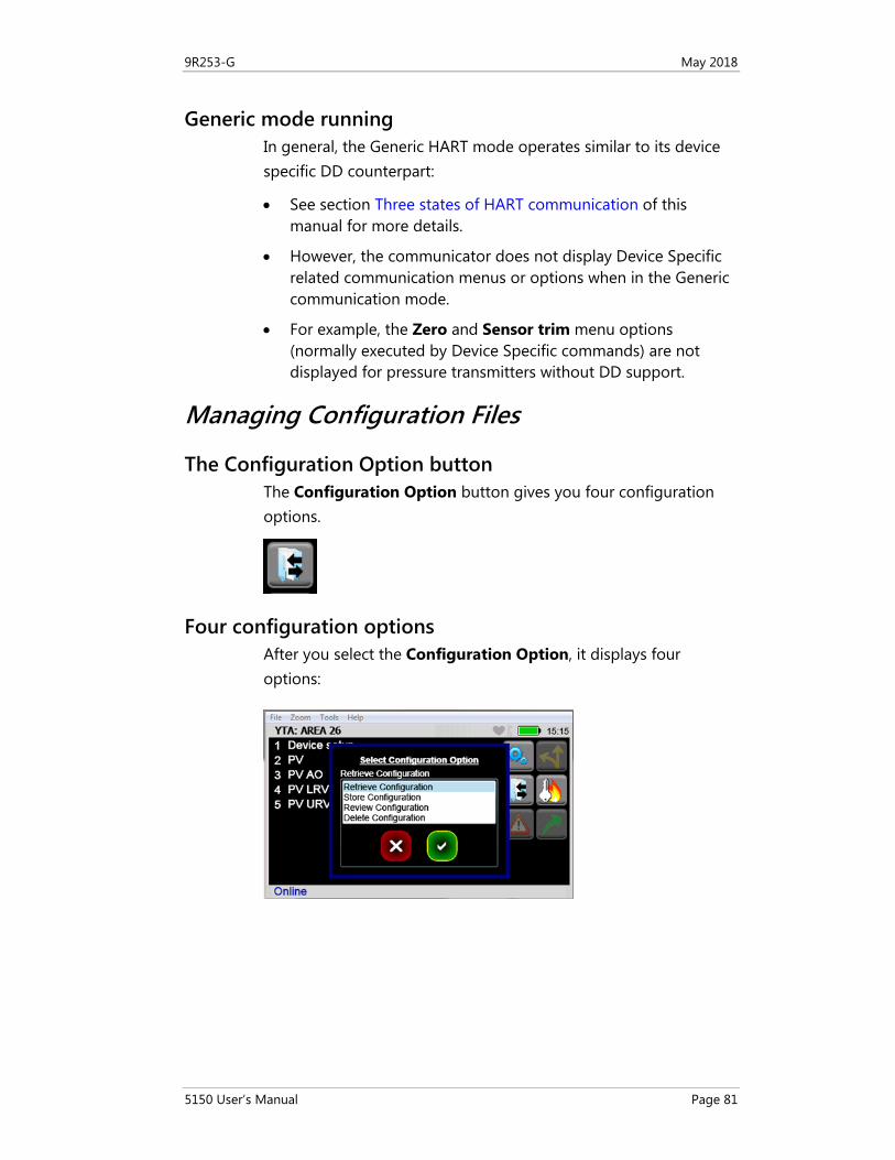
9R253-G May 2018
5150 User’s Manual Page 81
Generic mode running In general, the Generic HART mode operates similar to its device specific DD counterpart:
• See section Three states of HART communication of this manual for more details.
• However, the communicator does not display Device Specific related communication menus or options when in the Generic communication mode.
• For example, the Zero and Sensor trim menu options (normally executed by Device Specific commands) are not displayed for pressure transmitters without DD support.
Managing Configuration Files
The Configuration Option button The Configuration Option button gives you four configuration options.
Four configuration options After you select the Configuration Option, it displays four options:
9R253-G May 2018
5150 User’s Manual Page 82
First Option: Retrieve a device configuration
To retrieve a device configuration, you select the Configuration button.
• The configuration files are stored per device model and revision.
• When you select Retrieve configuration, only the configurations that pertain to the model of the connected device are displayed.
• You can select a file and select Accept. This retrieves the stored parameters to the communicator’s parameter cache.
• The parameter-changed indicator appears next to the affected parameters, and the Commit Changes button is illuminated.
• You now have the option of making further modifications to the parameters on the HART menu or committing them to the device.
Note: You cannot retrieve a configuration until all configuration parameters from the device load.
Second Option: Store files to µSD Memory Card
You may store the current parameter settings for a connected HART device as a file on the µSD system card for later use. This file can then be used:
• For duplicating settings to a new device of the same model.
• For restoring settings to a repaired device.
• For documentation purposes.
Note: You cannot retrieve a configuration until all configuration parameters from the device load.
Note: The manufacturer of the HART device defines what parameters are stored.
9R253-G May 2018
5150 User’s Manual Page 83
Configuration dialog boxes
Dialog boxes direct you to take the appropriate actions:
1. They prompt you for a file name. The default file name is the tag parameter defined in the device. You may change this to any file name not currently in use for this device model. If the user picks a name already in use, the communicator gives you an option of cancelling or overwriting the current file.
Note: Unsupported characters are unavailable and ignored.
2. If the configuration has not already been marked as As Modified, the user has to choose a configuration type. The choices are:
a. As Found (device settings before modification).
b. As Left (device settings after modification).
Note: The configuration file is saved in the communicator µSD memory card and can be retrieved to update any transmitter of the same model and revision.
Third option: Review Configuration
This option allows you to select a configuration to review all the parameters in it.
Fourth option: Delete Configuration
This option allows you to delete a configuration that you no longer want to keep.
Note: You do not need to delete configurations to save space on the memory card.
9R253-G May 2018
5150 User’s Manual Page 84
Commit Changes
If the Commit Changes button is illuminated, you should commit the communicator parameters to the device before you continue.
• If the parameters are not committed and you choose to store the parameters, you are warned that the parameters do not match the device.
• If you decide to continue to store the file, it is marked as As Modified.
Be careful when retrieving a configuration
Before retrieving a configuration, remember that Retrieving a Configuration overwrites any uncommitted configuration parameters that have not been committed to the device.
Important: Consider whether you need to Commit Changes to the device now to avoid losing any modified, uncommitted parameters.
9R253-G May 2018
5150 User’s Manual Page 85
Troubleshooting HART Communications
Troubleshooting: No Devices Found If a HART device is connected to the communicator but “Polling Address 0” appears or the device is not in the table of found devices, follow these steps:
1. Make sure all connections are correct and secure.
2. Check for shorts, open circuits, and multiple grounds.
3. Determine if the loop resistance is greater than 250 Ω and less than 1100 Ωs. If less than 250 Ω, then use the supplied 250 Ω load resistor in series with the loop (see the Wiring diagram: Loop resistance < 250 Ω in the Connecting the 5150 to Smart Transmitters section).
4. Determine if any device is in burst mode. Disable burst mode if possible during troubleshooting.
5. Check the polling address type and range selected from the system menus. If the polling address set on the transmitter is outside of the range selected for the communicator, it cannot discover the device.
a. Set the poll type to “by address” and set the polling address range to the maximum:
1. 0–15 for HART Universal Revision 5 devices. 2. 0–63 for newer HART devices.
b. Allow the communicator to poll and determine if the device is found.
6. If multiple HART devices are in the loop, there could be an address conflict (two devices at same address). Testing the devices individually is the best path.
7. Determine if there are multiple master devices on the loop. HART communication only permits one primary and one secondary master.
8. Remove all other secondary master devices from the loop for troubleshooting.
9R253-G May 2018
5150 User’s Manual Page 86
Troubleshooting: Generic When the message Generic displays after connecting to a HART device, there are two possible causes:
1. No device-specific DD for that device is currently installed in communicator memory. This could occur if the device DD has not been released by the HART Communication Foundation, or if the DD database on your computer requires updates. See the following resources:
Note: See the section Updating communicator software.
2. The connected HART device supports only HART Universal and Common Practice commands (for example: generic commands). There are several such devices on the market, particularly level type devices.
Troubleshooting: Multiple Devices If multiple devices of the same name appear at different addresses, the cause is normally a HART Universal Revision 5 device in the loop and the polling range selected on the communicator extending beyond HART polling address 15. This generally causes no problems and you may select any one of the duplicate entries to connect to the device.
Note: Addresses beyond 15 were undefined until HART Universal Revision 6.
Updating communicator software The following link contains the instructions and links necessary to update your communicator software:
• System files.
• DD files.
http://www.5150update.com/MFC5150 Update Procedure.pdf
9R253-G May 2018
5150 User’s Manual Page 87
Specifications
Approvals
5150X Intrinsically Safe model ATEX II 1 G; Ex ia IIC T4 Ga
cULus Listed Intrinsically Safe, Exia
Class I, Div. 1 Groups A, B, C, D: T4
–10 ºC < Ta < +50 ºC
IECEx UL 13.0004
Entity parameters: Pi = 1.25W, Ii = 200mA, Ci = 0, Li=0,
Vi=30V, Um (USB) = 5V,
Um (battery) = 5V
5150 General Purpose model
Display specifications 4.3-in. widescreen backlit TFT color touchscreen display with 480 x 272 WQVGA pixel resolution.
Ingress specifications • PC/ABS alloy plastic case with shock absorbing bumpers.
• The 5150 is rated IP51 (It passes a one-meter drop test onto concrete.)
• The 5150 weighs 2.1 lbs. including battery.
Power • Lithium-ion battery pack, 3.6 volts nominal.
• 1.5 A charging cradle. 100 Vac to 240 Vac, 50/60 Hz input.
εΧ
CE compliance
CE compliance
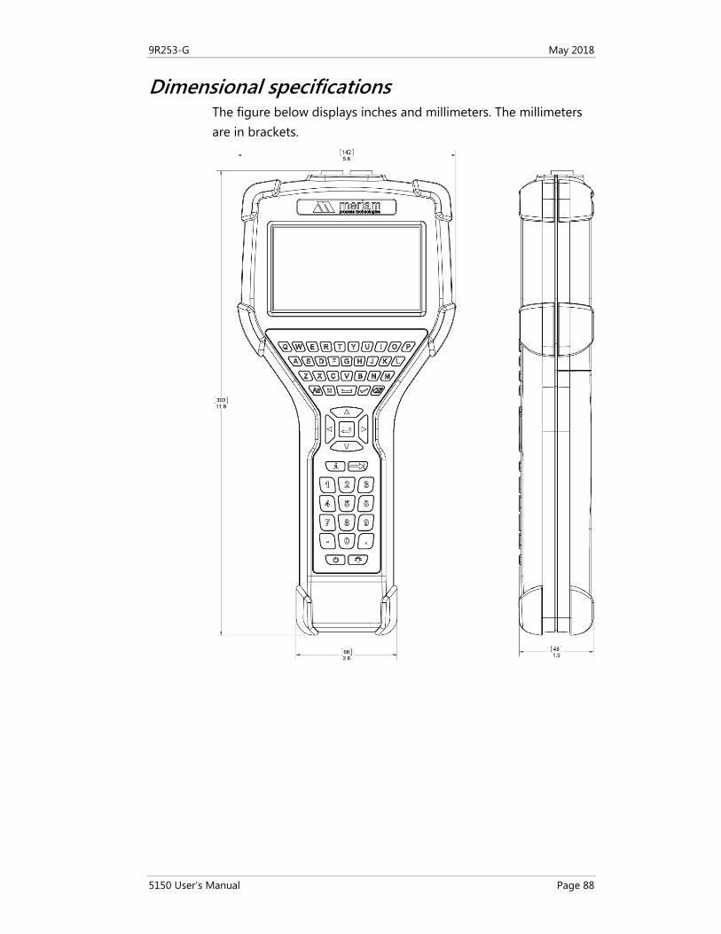
9R253-G May 2018
5150 User’s Manual Page 88
Dimensional specifications The figure below displays inches and millimeters. The millimeters are in brackets.
9R253-G May 2018
5150 User’s Manual Page 89
Battery life (Approximate) • 10 hours continuous use at the 100 % backlight setting
(typical).
Temperature specifications Storage: –40 °F to 140 °F (–40 °C to 60 °C)
Operating: 14 °F to 122 °F (–10 °C to 50 °C)
Charging: 50 °F to 104 °F (10 °C to 40 °C)
Communication connections • Standard banana jacks (¾ in. center) for HART communication.
• Communication (serial cable to computer port) / Battery charging. Connection via charging cradle.
Memory card • Dedicated µSD flash memory card for 5150 Series application
software, DD and configuration storage.
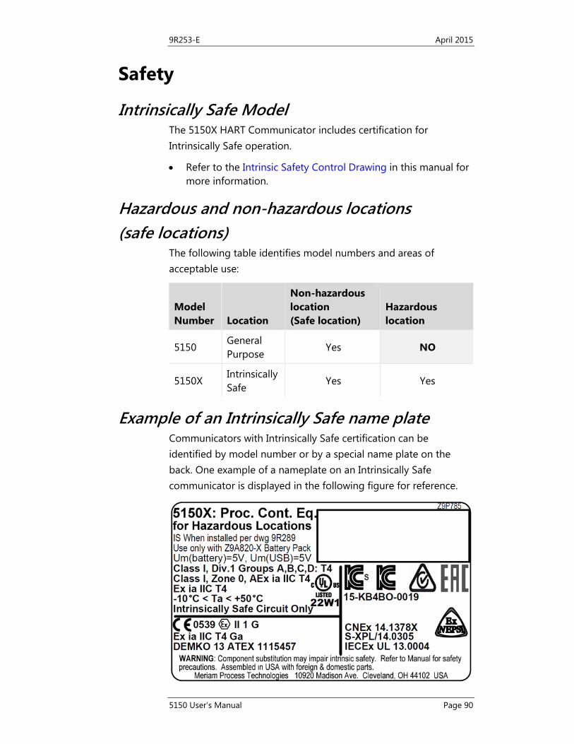
9R253-E April 2015
5150 User’s Manual Page 90
Safety
Intrinsically Safe Model The 5150X HART Communicator includes certification for Intrinsically Safe operation.
• Refer to the Intrinsic Safety Control Drawing in this manual for more information.
Hazardous and non-hazardous locations (safe locations)
The following table identifies model numbers and areas of acceptable use:
Model Number Location
Non-hazardous location (Safe location)
Hazardous location
5150 General Purpose
Yes NO
5150X Intrinsically Safe
Yes Yes
Example of an Intrinsically Safe name plate Communicators with Intrinsically Safe certification can be identified by model number or by a special name plate on the back. One example of a nameplate on an Intrinsically Safe communicator is displayed in the following figure for reference.
9R253-G May 2018
5150 User’s Manual Page 91
Hazardous locations: Warnings & Cautions
No substitutions
Important: Substituting components may impair Intrinsic Safety.
Preventing explosions
Important: To prevent ignition of flammable or explosive atmospheres:
• Disconnect power before servicing.
• Do not open or service the unit in flammable or explosive atmospheres.
• Never attempt to open the sealed battery pack to replace the cells.
Restrictions on electrical connections
• Serious injury or death may result from explosions.
• Before making electrical connections to an Intrinsically Safe model at the HART jacks, verify the HART instrument of interest is installed in accordance with intrinsically safe field-wiring practices.
Restrictions in hazardous locations
Restrictions apply to the use of Intrinsically Safe units in hazardous areas.
• Refer to Intrinsic Safety Control Drawing in this manual for more information.
• Meriam reserves the right to revise the Intrinsic Safety Control Drawing without notice.
• Contact Meriam for the current Intrinsic Safety Control Drawing.
US Customers 1 (800) 817-7849
International customers + 1 216 281 1100
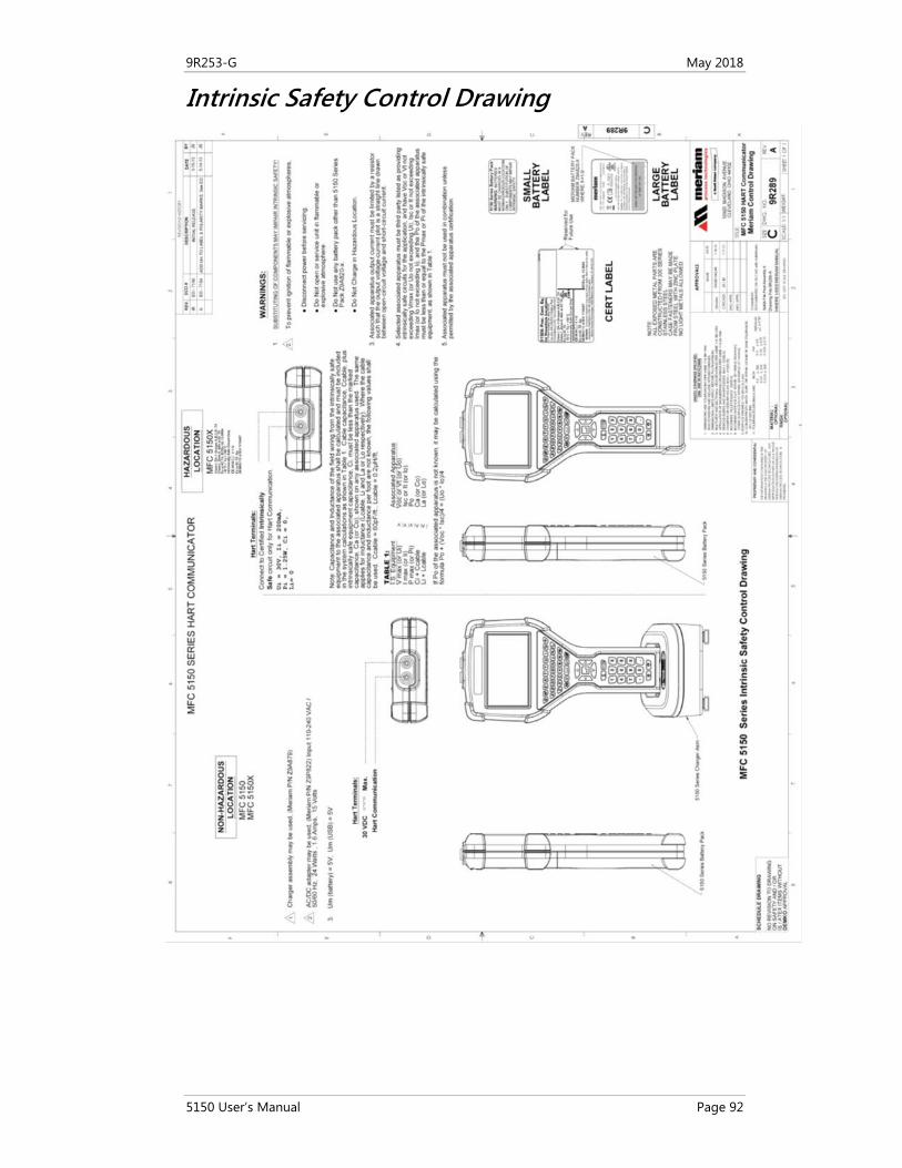
9R253-G May 2018
5150 User’s Manual Page 92
Intrinsic Safety Control Drawing

9R253-G May 2018
5150 User’s Manual Page 93
EC Declaration of Conformity Please go to the Meriam website https://www.meriam.com/certifications-table/ to review current EC Declarations of Conformity and other product certifications for the MFC5150.
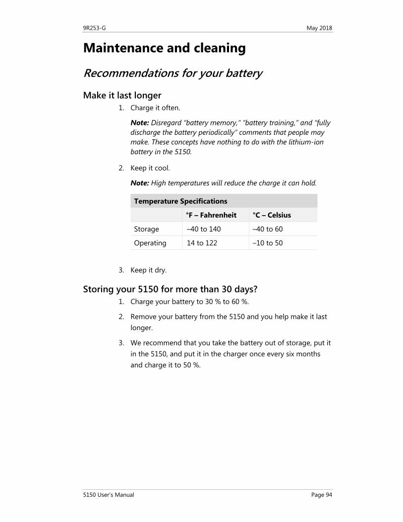
9R253-G May 2018
5150 User’s Manual Page 94
Maintenance and cleaning
Recommendations for your battery
Make it last longer 1. Charge it often.
Note: Disregard “battery memory,” “battery training,” and “fully discharge the battery periodically” comments that people may make. These concepts have nothing to do with the lithium-ion battery in the 5150.
2. Keep it cool.
Note: High temperatures will reduce the charge it can hold.
Temperature Specifications
°F – Fahrenheit °C – Celsius
Storage –40 to 140 –40 to 60
Operating 14 to 122 –10 to 50
3. Keep it dry.
Storing your 5150 for more than 30 days? 1. Charge your battery to 30 % to 60 %.
2. Remove your battery from the 5150 and you help make it last longer.
3. We recommend that you take the battery out of storage, put it in the 5150, and put it in the charger once every six months and charge it to 50 %.

9R253-E April 2015
5150 User’s Manual Page 95
Two factors affect your battery’s life in storage 1. Keep it in a cool storage location. High temperatures reduce
the amount of time it can hold a charge.
2. Make sure it has a 30 % to 60 % charge before you turn it off.
Note: Don’t charge it to 100 % before putting it in storage.
Important: Failing to follow the tips above will lead to a permanent reduction in the number of hours your battery can hold a charge.
Waste Electrical and Electronic Equipment (WEEE), Directive 2012/19/EU
European Union only Important: This directive is only valid in the EU.
• This product complies with the WEEE Directive (2012/19/EU) marking requirement.
• The following marking indicates that you must not discard this electrical / electronic product in domestic household waste.
European Union Product Category With reference to the equipment types in the WEEE directive Annex 1, this product is classified as a “Monitoring and Control Instrumentation” product.
• Do not dispose of it in domestic household waste.
• When disposing of products in the EU, contact your local Meriam representative.
9R253-E April 2015
5150 User’s Manual Page 96
US government agencies Check with the US Environmental Protection Agency (EPA), state agencies, and other local authorities before you dispose of electrical or electronic waste.
• The EPA www.epa.gov
• Remember that some state and local authorities have stricter requirements than federal requirements.
Other countries Check the requirements of your national and local regulations before you dispose of electrical or electronic waste.
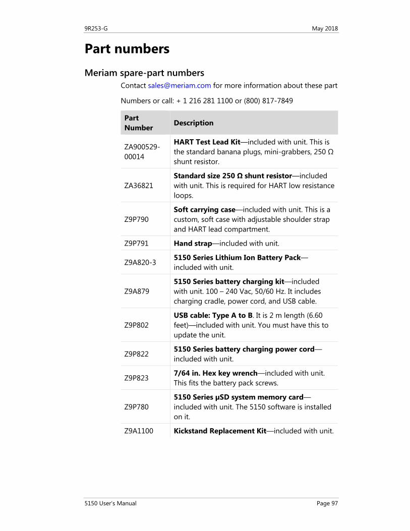
9R253-G May 2018
5150 User’s Manual Page 97
Part numbers
Meriam spare-part numbers Contact [email protected] for more information about these part
Numbers or call: + 1 216 281 1100 or (800) 817-7849
Part Number
Description
ZA900529-00014
HART Test Lead Kit—included with unit. This is the standard banana plugs, mini-grabbers, 250 Ω shunt resistor.
ZA36821 Standard size 250 Ω shunt resistor—included with unit. This is required for HART low resistance loops.
Z9P790 Soft carrying case—included with unit. This is a custom, soft case with adjustable shoulder strap and HART lead compartment.
Z9P791 Hand strap—included with unit.
Z9A820-3 5150 Series Lithium Ion Battery Pack—included with unit.
Z9A879 5150 Series battery charging kit—included with unit. 100 – 240 Vac, 50/60 Hz. It includes charging cradle, power cord, and USB cable.
Z9P802 USB cable: Type A to B. It is 2 m length (6.60 feet)—included with unit. You must have this to update the unit.
Z9P822 5150 Series battery charging power cord—included with unit.
Z9P823 7/64 in. Hex key wrench—included with unit. This fits the battery pack screws.
Z9P780 5150 Series µSD system memory card—included with unit. The 5150 software is installed on it.
Z9A1100 Kickstand Replacement Kit—included with unit.
9R253-G May 2018
5150 User’s Manual Page 98
Help
Register your product We want you to get the most out of your purchase, and that starts with a few, easy registration steps.
1. Go to www.meriam.com
2. On the Resources menu, click Register Your Product
Note: Or, click the link in step 2 to go directly to Register Your Product.
Find downloads and documents 1. Go to www.meriam.com/resources page.
2. Or, on the Resources menu, select one of these categories to find the files you need.
Product manuals | User Manuals and Quick Start Guides
Downloads | Applications (software), firmware, updates, installation instructions
Certifications | Certifications and approvals
SDS (MSDS) | Safety Data Sheets
Control Drawings | Intrinsically Safe Drawings
9R253-E April 2015
5150 User’s Manual Page 99
For repair or calibration
Contact Meriam for repair or calibration Meriam offers service and calibration on your products by certified technicians.
Reminder: You must have the model number and serial number ready when you contact us.
You have three options for requesting service:
Option 1: Complete and submit the For Repair & Calibration online form.
1. Go to www.meriam.com and click the Resources menu button.
2. Move the mouse pointer over For Repair & Calibration to see these two options:
a. Repair & Calibration.
b. RMA Request.
3. Complete either one online.
Reminders:
• You can see an estimated total price using the online form.
• You must include model number and serial number.
• Select Repair or Recalibration as the Service Type.
4. Click the Submit button to send the form to Meriam.
Option 2: Download a form to print and send to Meriam.
1. Click Service & Repair to see the link for Download form here in the first paragraph. You can download it and complete it later.
2. You can scan this form and send it by e-mail to [email protected] or fax it to us at:
+ 1 216 281 0228
USA and International Customers
Option 3: Call Meriam to request repair or calibration.
+ 1 216 281 1100
USA (800) 817-7849
9R253-E April 2015
5150 User’s Manual Page 100
Before you ship anything to Meriam
1. You must receive a RMA number from Meriam first.
2. Clearly write on the package or place a shipping label on it with the RMA number (Return Material Authorization Number).
Note: we will return the gauge or sensor at your expense if we have not given you an RMA number.
3. An RMA number must appear on all packages that arrive at Meriam to properly track, process, and repair your gauge.
Do you have any questions? Call Meriam + 1 216 281 1100
USA (800) 817-7849
Ship the box to Meriam 10920 Madison Avenue Cleveland | Ohio | 44102 USA
9R253-E April 2015
5150 User’s Manual Page 101
Meriam Contact Information
Address Meriam Process Technologies
10920 Madison Avenue
Cleveland | Ohio | 44102 | USA
Telephone US customers (800) 817-7849
International customers + 1 216 281 1100
Fax US & International customers + 1 216 281 0228
E-mail addresses Return Material Authorization / Service & Repair Department
Sales
Website www.meriam.com
Find a local Meriam representative Use this map to help you find a Meriam representative.
http://www.meriam.com/representatives-map/


![Instruments [Meriam]](https://img.pdfslide.us/doc/110x75/577d20701a28ab4e1e92e288/instruments-meriam.jpg)