Embed Size (px)
Citation preview

Large changes in tension can occur when a line is wrapped around a fixed cylinder.
© STOCK4B-RoyaltyFree/Image Source

335
6/1 Introduction
Section A Frictional Phenomena
6/2 Types of Friction
6/3 Dry Friction
Section B Applications of Friction in Machines
6/4 Wedges
6/5 Screws
6/6 Journal Bearings
6/7 Thrust Bearings; Disk Friction
6/8 Flexible Belts
6/9 Rolling Resistance
6/10 Chapter Review
CHAPTER OUTLINE
6Friction
6/1 IntroductionIn the preceding chapters we have usually assumed that the forces
of action and reaction between contacting surfaces act normal to thesurfaces. This assumption characterizes the interaction between smoothsurfaces and was illustrated in Example 2 of Fig. 3/1. Although thisideal assumption often involves only a relatively small error, there aremany problems in which we must consider the ability of contacting sur-faces to support tangential as well as normal forces. Tangential forcesgenerated between contacting surfaces are called friction forces andoccur to some degree in the interaction between all real surfaces. When-ever a tendency exists for one contacting surface to slide along anothersurface, the friction forces developed are always in a direction to opposethis tendency.
In some types of machines and processes we want to minimize theretarding effect of friction forces. Examples are bearings of all types,power screws, gears, the flow of fluids in pipes, and the propulsion ofaircraft and missiles through the atmosphere. In other situations wewish to maximize the effects of friction, as in brakes, clutches, beltdrives, and wedges. Wheeled vehicles depend on friction for both start-ing and stopping, and ordinary walking depends on friction between theshoe and the ground.

Friction forces are present throughout nature and exist in all ma-chines no matter how accurately constructed or carefully lubricated. Amachine or process in which friction is small enough to be neglected issaid to be ideal. When friction must be taken into account, the machineor process is termed real. In all cases where there is sliding motion be-tween parts, the friction forces result in a loss of energy which is dissi-pated in the form of heat. Wear is another effect of friction.
SECTION A FRICTIONAL PHENOMENA
6/2 Types of FrictionIn this article we briefly discuss the types of frictional resistance en-
countered in mechanics. The next article contains a more detailed ac-count of the most common type of friction, dry friction.
(a) Dry Friction. Dry friction occurs when the unlubricated surfacesof two solids are in contact under a condition of sliding or a tendency toslide. A friction force tangent to the surfaces of contact occurs both dur-ing the interval leading up to impending slippage and while slippagetakes place. The direction of this friction force always opposes the mo-tion or impending motion. This type of friction is also called Coulombfriction. The principles of dry or Coulomb friction were developedlargely from the experiments of Coulomb in 1781 and from the work ofMorin from 1831 to 1834. Although we do not yet have a comprehensivetheory of dry friction, in Art. 6/3 we describe an analytical model suffi-cient to handle the vast majority of problems involving dry friction. Thismodel forms the basis for most of this chapter.
(b) Fluid Friction. Fluid friction occurs when adjacent layers in afluid (liquid or gas) are moving at different velocities. This motioncauses frictional forces between fluid elements, and these forces dependon the relative velocity between layers. When there is no relative veloc-ity, there is no fluid friction. Fluid friction depends not only on the ve-locity gradients within the fluid but also on the viscosity of the fluid,which is a measure of its resistance to shearing action between fluid lay-ers. Fluid friction is treated in the study of fluid mechanics and will notbe discussed further in this book.
(c) Internal Friction. Internal friction occurs in all solid materialswhich are subjected to cyclical loading. For highly elastic materials therecovery from deformation occurs with very little loss of energy due tointernal friction. For materials which have low limits of elasticity andwhich undergo appreciable plastic deformation during loading, a consid-erable amount of internal friction may accompany this deformation.The mechanism of internal friction is associated with the action of sheardeformation, which is discussed in references on materials science. Be-cause this book deals primarily with the external effects of forces, wewill not discuss internal friction further.
336 Chapter 6 Friction

6/3 Dry FrictionThe remainder of this chapter describes the effects of dry friction
acting on the exterior surfaces of rigid bodies. We will now explain themechanism of dry friction with the aid of a very simple experiment.
Mechanism of Dry FrictionConsider a solid block of mass m resting on a horizontal surface, as
shown in Fig. 6/1a. We assume that the contacting surfaces have someroughness. The experiment involves the application of a horizontal forceP which continuously increases from zero to a value sufficient to movethe block and give it an appreciable velocity. The free-body diagram ofthe block for any value of P is shown in Fig. 6/1b, where the tangentialfriction force exerted by the plane on the block is labeled F. This frictionforce acting on the body will always be in a direction to oppose motionor the tendency toward motion of the body. There is also a normal forceN which in this case equals mg, and the total force R exerted by the sup-porting surface on the block is the resultant of N and F.
A magnified view of the irregularities of the mating surfaces, Fig.6/1c, helps us to visualize the mechanical action of friction. Support isnecessarily intermittent and exists at the mating humps. The directionof each of the reactions on the block, R1, R2, R3, etc. depends not only onthe geometric profile of the irregularities but also on the extent of localdeformation at each contact point. The total normal force N is the sum
Article 6/3 Dry Friction 337
Pm P
F
αRN
mg
(a)
(c)
t
n
F
F = P
Fmax = s Nμ Fk = k Nμ
R1 R3R2
(b)
P
Staticfriction
(no motion)
Kineticfriction(motion)
Impendingmotion
(d)
Figure 6/1

of the n-components of the R’s, and the total frictional force F is thesum of the t-components of the R’s. When the surfaces are in relativemotion, the contacts are more nearly along the tops of the humps, andthe t-components of the R’s are smaller than when the surfaces are atrest relative to one another. This observation helps to explain the well-known fact that the force P necessary to maintain motion is generallyless than that required to start the block when the irregularities aremore nearly in mesh.
If we perform the experiment and record the friction force F as afunction of P, we obtain the relation shown in Fig. 6/1d. When P iszero, equilibrium requires that there be no friction force. As P is in-creased, the friction force must be equal and opposite to P as long asthe block does not slip. During this period the block is in equilibrium,and all forces acting on the block must satisfy the equilibrium equa-tions. Finally, we reach a value of P which causes the block to slip andto move in the direction of the applied force. At this same time thefriction force decreases slightly and abruptly. It then remains essen-tially constant for a time but then decreases still more as the velocityincreases.
Static FrictionThe region in Fig. 6/1d up to the point of slippage or impending mo-
tion is called the range of static friction, and in this range the value ofthe friction force is determined by the equations of equilibrium. Thisfriction force may have any value from zero up to and including themaximum value. For a given pair of mating surfaces the experimentshows that this maximum value of static friction Fmax is proportional tothe normal force N. Thus, we may write
(6/1)
where �s is the proportionality constant, called the coefficient of staticfriction.
Be aware that Eq. 6/1 describes only the limiting or maximum valueof the static friction force and not any lesser value. Thus, the equationapplies only to cases where motion is impending with the friction forceat its peak value. For a condition of static equilibrium when motion isnot impending, the static friction force is
Kinetic FrictionAfter slippage occurs, a condition of kinetic friction accompanies the
ensuing motion. Kinetic friction force is usually somewhat less than themaximum static friction force. The kinetic friction force Fk is also pro-portional to the normal force. Thus,
(6/2)Fk � �kN
F � �sN
Fmax � �sN
338 Chapter 6 Friction
where �k is the coefficient of kinetic friction. It follows that �k is gener-ally less than �s. As the velocity of the block increases, the kinetic fric-tion decreases somewhat, and at high velocities, this decrease may besignificant. Coefficients of friction depend greatly on the exact conditionof the surfaces, as well as on the relative velocity, and are subject to con-siderable uncertainty.
Because of the variability of the conditions governing the action offriction, in engineering practice it is frequently difficult to distinguishbetween a static and a kinetic coefficient, especially in the region oftransition between impending motion and motion. Well-greased screwthreads under mild loads, for example, often exhibit comparable fric-tional resistance whether they are on the verge of turning or whetherthey are in motion.
In the engineering literature we frequently find expressions for max-imum static friction and for kinetic friction written simply as F � �N. Itis understood from the problem at hand whether maximum static fric-tion or kinetic friction is described. Although we will frequently distin-guish between the static and kinetic coefficients, in other cases nodistinction will be made, and the friction coefficient will be writtensimply as �. In those cases you must decide which of the friction condi-tions, maximum static friction for impending motion or kinetic fric-tion, is involved. We emphasize again that many problems involve astatic friction force which is less than the maximum value at impend-ing motion, and therefore under these conditions the friction relationEq. 6/1 cannot be used.
Figure 6/1c shows that rough surfaces are more likely to havelarger angles between the reactions and the n-direction than aresmoother surfaces. Thus, for a pair of mating surfaces, a friction coef-ficient reflects the roughness, which is a geometric property of thesurfaces. With this geometric model of friction, we describe matingsurfaces as “smooth” when the friction forces they can support arenegligibly small. It is meaningless to speak of a coefficient of frictionfor a single surface.
Friction AnglesThe direction of the resultant R in Fig. 6/1b measured from the
direction of N is specified by tan � � F/N. When the friction forcereaches its limiting static value Fmax, the angle � reaches a maximumvalue �s. Thus,
When slippage is occurring, the angle � has a value �k corresponding tothe kinetic friction force. In like manner,
In practice we often see the expression tan � � �, in which thecoefficient of friction may refer to either the static or the kinetic case,
tan �k � �k
tan �s � �s
Article 6/3 Dry Friction 339
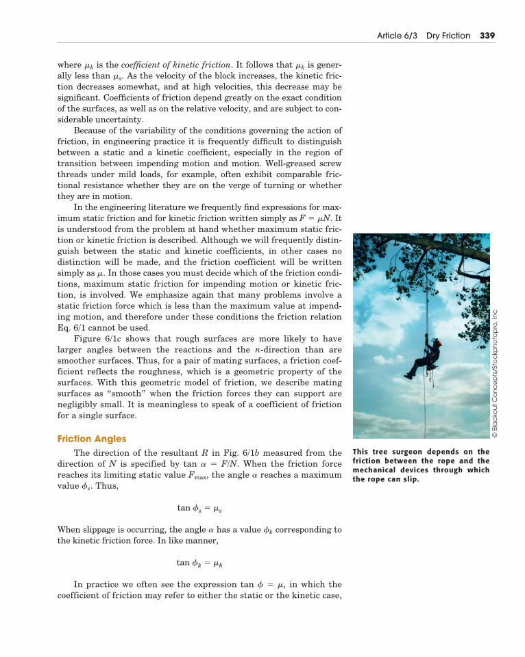
This tree surgeon depends on thefriction between the rope and themechanical devices through whichthe rope can slip.
© B
lac
kou
t C
on
ce
pts
/Sto
ckp
ho
top
ro, I
nc

depending on the particular problem. The angle �s is called the angle ofstatic friction, and the angle �k is called the angle of kinetic friction. Thefriction angle for each case clearly defines the limiting direction of thetotal reaction R between two contacting surfaces. If motion is impend-ing, R must be one element of a right-circular cone of vertex angle 2�s,as shown in Fig. 6/2. If motion is not impending, R is within the cone.This cone of vertex angle 2�s is called the cone of static friction and rep-resents the locus of possible directions for the reaction R at impendingmotion. If motion occurs, the angle of kinetic friction applies, and thereaction must lie on the surface of a slightly different cone of vertexangle 2�k. This cone is the cone of kinetic friction.
Factors Affecting FrictionFurther experiment shows that the friction force is essentially in-
dependent of the apparent or projected area of contact. The true con-tact area is much smaller than the projected value, since only the peaksof the contacting surface irregularities support the load. Even rela-tively small normal loads result in high stresses at these contact points.As the normal force increases, the true contact area also increases asthe material undergoes yielding, crushing, or tearing at the points ofcontact.
A comprehensive theory of dry friction must go beyond the mechan-ical explanation presented here. For example, there is evidence thatmolecular attraction may be an important cause of friction under condi-tions where the mating surfaces are in very close contact. Other factorswhich influence dry friction are the generation of high local tempera-tures and adhesion at contact points, relative hardness of mating sur-faces, and the presence of thin surface films of oxide, oil, dirt, or othersubstances.
Some typical values of coefficients of friction are given in Table D/1,Appendix D. These values are only approximate and are subject to con-siderable variation, depending on the exact conditions prevailing. Theymay be used, however, as typical examples of the magnitudes of fric-tional effects. To make a reliable calculation involving friction, theappropriate friction coefficient should be determined by experimentswhich duplicate the surface conditions of the application as closely aspossible.
340 Chapter 6 Friction
Cone ofstatic friction
2 kφ2 sφ
Cone ofkinetic friction
R
Figure 6/2
Article 6/3 Dry Friction 341
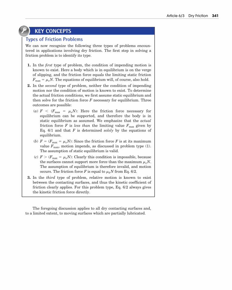
Types of Friction ProblemsWe can now recognize the following three types of problems encoun-tered in applications involving dry friction. The first step in solving afriction problem is to identify its type.
1. In the first type of problem, the condition of impending motion isknown to exist. Here a body which is in equilibrium is on the vergeof slipping, and the friction force equals the limiting static frictionFmax � �sN. The equations of equilibrium will, of course, also hold.
2. In the second type of problem, neither the condition of impendingmotion nor the condition of motion is known to exist. To determinethe actual friction conditions, we first assume static equilibrium andthen solve for the friction force F necessary for equilibrium. Threeoutcomes are possible:
(a) F � (Fmax � �sN): Here the friction force necessary for equilibrium can be supported, and therefore the body is in static equilibrium as assumed. We emphasize that the actualfriction force F is less than the limiting value Fmax given by Eq. 6/1 and that F is determined solely by the equations of equilibrium.
(b) F � (Fmax � �sN): Since the friction force F is at its maximumvalue Fmax, motion impends, as discussed in problem type (1).The assumption of static equilibrium is valid.
(c) F � (Fmax � �sN): Clearly this condition is impossible, becausethe surfaces cannot support more force than the maximum �sN.The assumption of equilibrium is therefore invalid, and motionoccurs. The friction force F is equal to �kN from Eq. 6/2.
3. In the third type of problem, relative motion is known to exist between the contacting surfaces, and thus the kinetic coefficient offriction clearly applies. For this problem type, Eq. 6/2 always givesthe kinetic friction force directly.
KEY CONCEPTS
The foregoing discussion applies to all dry contacting surfaces and,to a limited extent, to moving surfaces which are partially lubricated.

SAMPLE PROBLEM 6/1
Determine the maximum angle � which the adjustable incline may havewith the horizontal before the block of mass m begins to slip. The coefficient ofstatic friction between the block and the inclined surface is �s.
Solution. The free-body diagram of the block shows its weight W � mg, thenormal force N, and the friction force F exerted by the incline on the block. Thefriction force acts in the direction to oppose the slipping which would occur if nofriction were present.
Equilibrium in the x- and y-directions requires
Dividing the first equation by the second gives F/N � tan �. Since the maximumangle occurs when F � Fmax � �sN, for impending motion we have
Ans.
SAMPLE PROBLEM 6/2
Determine the range of values which the mass m0 may have so that the 100-kgblock shown in the figure will neither start moving up the plane nor slip downthe plane. The coefficient of static friction for the contact surfaces is 0.30.
Solution. The maximum value of m0 will be given by the requirement for mo-tion impending up the plane. The friction force on the block therefore acts downthe plane, as shown in the free-body diagram of the block for Case I in the figure.With the weight mg � 100(9.81) � 981 N, the equations of equilibrium give
Ans.
The minimum value of m0 is determined when motion is impending down theplane. The friction force on the block will act up the plane to oppose the ten-dency to move, as shown in the free-body diagram for Case II. Equilibrium in thex-direction requires
Ans.
Thus, m0 may have any value from 6.01 to 62.4 kg, and the block will remain atrest.
In both cases equilibrium requires that the resultant of Fmax and N be con-current with the 981-N weight and the tension T.
m0(9.81) � 277 � 981 sin 20� � 0 m0 � 6.01 kg[ΣFx � 0]
m0(9.81) � 277 � 981 sin 20� � 0 m0 � 62.4 kg[ΣFx � 0]
Fmax � 0.30(922) � 277 N[Fmax � �sN]
N � 981 cos 20� � 0 N � 922 N[ΣFy � 0]
�s � tan �max or �max � tan�1 �s
�mg cos � � N � 0 N � mg cos �[ΣFy � 0]
mg sin � � F � 0 F � mg sin �[ΣFx � 0]
342 Chapter 6 Friction
m
θsμ
x
y
F N
W = mg
θ
20° m0
100 kg
20°
981 N
N
Case I
x
y
Fmax
Fmax
T = m0g
20°
981 N
N
Case II
x
y
T = m0g
�
�
�
Helpful Hints
� We choose reference axes along andnormal to the direction of F toavoid resolving both F and N intocomponents.
� This problem describes a very simpleway to determine a static coefficientof friction. The maximum value of �is known as the angle of repose.
Helpful Hint
� We see from the results of SampleProblem 6/1 that the block wouldslide down the incline without the re-straint of attachment to m0 since tan20� � 0.30. Thus, a value of m0 willbe required to maintain equilibrium.

SAMPLE PROBLEM 6/3
Determine the magnitude and direction of the friction force acting on the100-kg block shown if, first, P � 500 N and, second, P � 100 N. The coefficient ofstatic friction is 0.20, and the coefficient of kinetic friction is 0.17. The forces areapplied with the block initially at rest.
Solution. There is no way of telling from the statement of the problem whetherthe block will remain in equilibrium or whether it will begin to slip following theapplication of P. It is therefore necessary that we make an assumption, so we willtake the friction force to be up the plane, as shown by the solid arrow. From thefree-body diagram a balance of forces in both x- and y-directions gives
Case I. P � 500 NSubstitution into the first of the two equations gives
The negative sign tells us that if the block is in equilibrium, the friction forceacting on it is in the direction opposite to that assumed and therefore is downthe plane, as represented by the dashed arrow. We cannot reach a conclusion onthe magnitude of F, however, until we verify that the surfaces are capable ofsupporting 134.3 N of friction force. This may be done by substituting P � 500 Ninto the second equation, which gives
The maximum static friction force which the surfaces can support is then
Since this force is greater than that required for equilibrium, we conclude thatthe assumption of equilibrium was correct. The answer is, then,
Ans.
Case II. P � 100 NSubstitution into the two equilibrium equations gives
But the maximum possible static friction force is
It follows that 242 N of friction cannot be supported. Therefore, equilibrium cannotexist, and we obtain the correct value of the friction force by using the kinetic coeffi-cient of friction accompanying the motion down the plane. Hence, the answer is
Ans.F � 0.17(956) � 162.5 N up the plane[Fk � �kN ]
Fmax � 0.20(956) � 191.2 N[Fmax � �sN ]
F � 242 N N � 956 N
F � 134.3 N down the plane
Fmax � 0.20(1093) � 219 N[Fmax � �sN ]
N � 1093 N
F � �134.3 N
N � P sin 20� � 981 cos 20� � 0[ΣFy � 0]
P cos 20� � F � 981 sin 20� � 0[ΣFx � 0]
Article 6/3 Dry Friction 343
20°
P 100 kg
20°
100(9.81) = 981 N
P
N
F
x
y
F
�
Helpful Hint
� We should note that even though ΣFx
is no longer equal to zero, equilibriumdoes exist in the y-direction, so thatΣFy � 0. Therefore, the normal forceN is 956 N whether or not the block isin equilibrium.

SAMPLE PROBLEM 6/4
The homogeneous rectangular block of mass m, width b, and height H isplaced on the horizontal surface and subjected to a horizontal force P whichmoves the block along the surface with a constant velocity. The coefficient of ki-netic friction between the block and the surface is �k. Determine (a) the greatestvalue which h may have so that the block will slide without tipping over and (b) the location of a point C on the bottom face of the block through which theresultant of the friction and normal forces acts if h � H/2.
Solution. (a) With the block on the verge of tipping, we see that the entire re-action between the plane and the block will necessarily be at A. The free-bodydiagram of the block shows this condition. Since slipping occurs, the frictionforce is the limiting value �kN, and the angle � becomes � � tan�1 �k. The resul-tant of Fk and N passes through a point B through which P must also pass, sincethree coplanar forces in equilibrium are concurrent. Hence, from the geometryof the block
Ans.
If h were greater than this value, moment equilibrium about A would not besatisfied, and the block would tip over.
Alternatively, we may find h by combining the equilibrium requirements forthe x- and y-directions with the moment-equilibrium equation about A. Thus,
Ans.
(b) With h � H/2 we see from the free-body diagram for case (b) that the re-sultant of Fk and N passes through a point C which is a distance x to the left ofthe vertical centerline through G. The angle � is still � � � � tan�1 �k as long asthe block is slipping. Thus, from the geometry of the figure we have
Ans.
If we were to replace �k by the static coefficient �s, then our solutions woulddescribe the conditions under which the block is (a) on the verge of tipping and(b) on the verge of slipping, both from a rest position.
xH/2
� tan � � �k so x � �kH/2
Ph � mg b2
� 0 h �mgb2P
�mgb
2�kmg�
b2�k
[ΣMA � 0]
Fk � P � 0 P � Fk � �kN � �kmg[ΣFx � 0]
N � mg � 0 N � mg[ΣFy � 0]
tan � � �k �b/2h
h �b
2�k
344 Chapter 6 Friction
Pm
b
Hh
PG
mg
θ
θ
x
y
B
A
N
Fk
h
b—2
PG
mgθ
θ
C
N
xFk
H—2
�
�
Helpful Hints
� Recall that the equilibrium equa-tions apply to a body moving with aconstant velocity (zero acceleration)just as well as to a body at rest.
� Alternatively, we could equate themoments about G to zero, whichwould give us F(H/2) � Nx � 0. Thus,with Fk � �kN we get x � �xH/2.

SAMPLE PROBLEM 6/5
The three flat blocks are positioned on the 30� incline as shown, and a forceP parallel to the incline is applied to the middle block. The upper block is pre-vented from moving by a wire which attaches it to the fixed support. The coeffi-cient of static friction for each of the three pairs of mating surfaces is shown.Determine the maximum value which P may have before any slipping takesplace.
Solution. The free-body diagram of each block is drawn. The friction forcesare assigned in the directions to oppose the relative motion which would occur if no friction were present. There are two possible conditions for impending mo-tion. Either the 50-kg block slips and the 40-kg block remains in place, or the 50-and 40-kg blocks move together with slipping occurring between the 40-kg blockand the incline.
The normal forces, which are in the y-direction, may be determined withoutreference to the friction forces, which are all in the x-direction. Thus,
We will assume arbitrarily that only the 50-kg block slips, so that the 40-kgblock remains in place. Thus, for impending slippage at both surfaces of the 50-kg block, we have
The assumed equilibrium of forces at impending motion for the 50-kg blockgives
We now check on the validity of our initial assumption. For the 40-kg blockwith F2 � 272 N the friction force F3 would be given by
But the maximum possible value of F3 is F3 � �sN3 � 0.45(1019) � 459 N. Thus,468 N cannot be supported and our initial assumption was wrong. We conclude,therefore, that slipping occurs first between the 40-kg block and the incline.With the corrected value F3 � 459 N, equilibrium of the 40-kg block for its im-pending motion requires
Equilibrium of the 50-kg block gives, finally,
Ans.
Thus, with P � 93.8 N, motion impends for the 50-kg and 40-kg blocks as a unit.
P � 93.8 N
P � 50(9.81) sin 30� � 263 � 76.5 � 0[ΣFx � 0]
F2 � 40(9.81) sin 30� � 459 � 0 F2 � 263 N[ΣFx � 0]
272 � 40(9.81) sin 30� � F3 � 0 F3 � 468 N[ΣFx � 0]
P � 76.5 � 272 � 50(9.81) sin 30� � 0 P � 103.1 N[ΣFx � 0]
F1 � 0.30(255) � 76.5 N F2 � 0.40(680) � 272 N[Fmax � �sN]
(40-kg) N3 � 40(9.81) cos 30� � 680 � 0 N3 � 1019 N
(50-kg) N2 � 50(9.81) cos 30� � 255 � 0 N2 � 680 N
(30-kg) N1 � 30(9.81) cos 30� � 0 N1 � 255 N[ΣFy � 0]
Article 6/3 Dry Friction 345
P
30 kg
s = 0.30
μ
s = 0.40
μ
50 kg
40 kg
30°
s = 0.45
μ
30°
y
P
F1
F2
N2
N1
50(9.81) N
x
y
F1
T
N1
30(9.81) N
x
xy
F2
F3
N3
N2
40(9.81) N
Helpful Hints
� In the absence of friction the middleblock, under the influence of P,would have a greater movementthan the 40-kg block, and the fric-tion force F2 will be in the directionto oppose this motion as shown.
� We see now that F2 is less than�sN2 � 272 N.
�
�

6/4 The coefficients of static and kinetic friction be-tween the 100-kg block and the inclined plane are0.30 and 0.20, respectively. Determine (a) the fric-tion force F acting on the block when P is appliedwith a magnitude of 200 N to the block at rest, (b) the force P required to initiate motion up the in-cline from rest, and (c) the friction force F acting onthe block if P = 600 N.
Problem 6/4
6/5 The magnitude of force P is slowly increased. Doesthe homogeneous box of mass m slip or tip first?State the value of P which would cause each occur-rence. Neglect any effect of the size of the smallfeet.
Problem 6/5
P
d
A
B C
2d
30°
s = 0.50μm
20°
15°
100 kg
P
s = 0.30μk = 0.20μ
346 Chapter 6 Friction
PROBLEMSIntroductory Problems
6/1 The 85-lb force P is applied to the 200-lb crate,which is stationary before the force is applied. De-termine the magnitude and direction of the frictionforce F exerted by the horizontal surface on thecrate.
Problem 6/1
6/2 The 700-N force is applied to the 100-kg block,which is stationary before the force is applied. De-termine the magnitude and direction of the frictionforce F exerted by the horizontal surface on theblock.
Problem 6/2
6/3 The designer of a ski resort wishes to have a portionof a beginner’s slope on which the skier’s speed willremain fairly constant. Tests indicate the average coefficients of friction between skis and snow to be
and . What should be the slopeangle of the constant-speed section?
Problem 6/3
θ
�
�k � 0.08�s � 0.10
100 kg
30°
P = 700 N
s = 0.80μ
k = 0.60μ
P = 85 lb
200 lb
s = 0.50μ
k = 0.40μ

6/6 Determine the magnitude and direction of the fric-tion force which the vertical wall exerts on the 100-lbblock if (a) and (b) .
Problem 6/6
6/7 Determine the minimum coefficient of static frictionwhich will allow the drum with fixed inner hub to
be rolled up the incline at a steady speed withoutslipping. What are the corresponding values of theforce P and the friction force F?
Problem 6/7
6/8 The tongs are designed to handle hot steel tubeswhich are being heat-treated in an oil bath. For a
jaw opening, what is the minimum coefficientof static friction between the jaws and the tubewhich will enable the tongs to grip the tube with-out slipping?
20�
30°
P
15°
m
rr/2 sμ
15�
�s
100 lb
P = 120 lbs = 0.50
θ
μk = 0.40μ
� � 30�� � 15�
Article 6/3 Problems 347
Problem 6/8
6/9 The light bar is used to support the 50-kg block inits vertical guides. If the coefficient of static fric-tion is 0.30 at the upper end of the bar and 0.40 atthe lower end of the bar, find the friction force act-ing at each end for x = 75 mm. Also find the maxi-mum value of x for which the bar will not slip.
Problem 6/9
6/10 The semicircular 5-kg plate rotates about a fixedbearing at O that can exert a maximum frictionalmoment of 1.2 N m on the plate. The horizontalforce P is applied to a cord wrapped around the plateperiphery and pinned at A. (a) With P = 0, deter-mine the maximum angle for which equilibrium is possible. (b) From the position determined in (a) calculate the force P required to rotate the bodycounterclockwise.
Problem 6/10
P
θOA 0.2 m
�
�
50 kg
x
300
mm
A
B
F
F
20°

Problem 6/13
6/14 The illustration shows the design of a cam-typelocking device, which, in the presence of sufficientfriction, limits the movement of body B to be to theleft only; rightward movement is prevented. Thesurface of the cam near point D is circular with cen-ter at C. Given the distance L, specify the cam offsetd so that the device will work if the coefficient ofstatic friction is 0.20 or greater.
Problem 6/14
6/15 The uniform slender bar has an ideal roller at itsupper end A. If the coefficient of static friction at Bis , determine the minimum angle forwhich equilibrium is possible. Repeat for .
Problem 6/15
B
A
θms = 0.25, 0.50
�s � 0.50��s � 0.25
OC
d
AL
Allowablemotion
Nomotion
DB
�s
25 lb
24′′
100 lb
3′′
8′′
θ
348 Chapter 6 Friction
6/11 The homogeneous body with two small feet and twoideal wheels is at rest on the rough incline. (a) As-sume no slippage and determine the maximum valueof the angle for which the body does not overturnabout feet A. (b) If , determine the maxi-mum value of the angle for which the body doesnot slip. (c) If and side C of the body nowfaces up the incline, determine the maximum valueof the angle for which the body does not slip.
Problem 6/11
6/12 The strut AB of negligible mass is hinged to the hori-zontal surface at A and to the uniform 25-kg wheel at B. Determine the minimum couple M applied to thewheel which will cause it to slip if the coefficient of sta-tic friction between the wheel and the surface is 0.40.
Problem 6/12
Representative Problems
6/13 The 100-lb wheel rolls on its hub up the circular in-cline under the action of the 25-lb weight attachedto a cord around the rim. Determine the angle atwhich the wheel comes to rest, assuming that fric-tion is sufficient to prevent slippage. What is theminimum coefficient of friction which will permitthis position to be reached with no slipping?
�
A
B 150 m
m
250 mm
M
h/4
h/2
h/4
h/2
C
G
A
B
q
ms
�
�s � 0.40�
�s � 0.40�
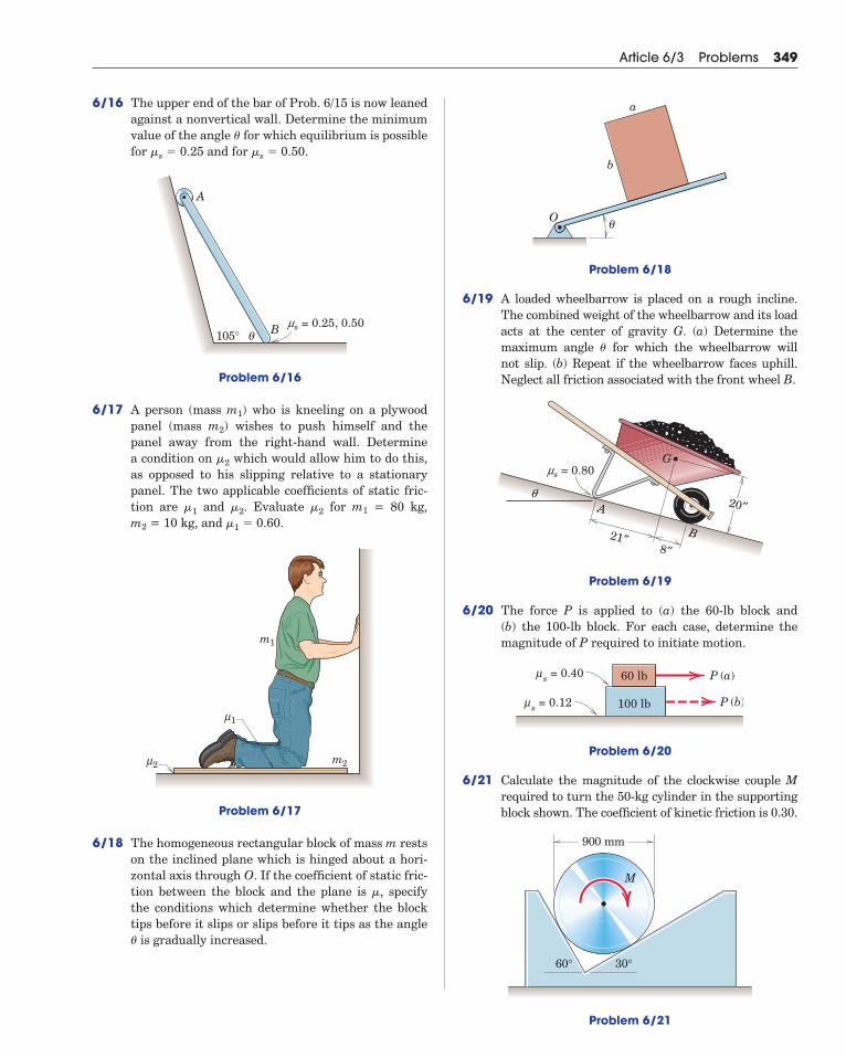
6/16 The upper end of the bar of Prob. 6/15 is now leanedagainst a nonvertical wall. Determine the minimumvalue of the angle for which equilibrium is possiblefor and for .
Problem 6/16
6/17 A person (mass m1) who is kneeling on a plywoodpanel (mass m2) wishes to push himself and thepanel away from the right-hand wall. Determine a condition on which would allow him to do this,as opposed to his slipping relative to a stationarypanel. The two applicable coefficients of static fric-tion are and . Evaluate for m1 = 80 kg, m2 = 10 kg, and .
Problem 6/17
6/18 The homogeneous rectangular block of mass m restson the inclined plane which is hinged about a hori-zontal axis through O. If the coefficient of static fric-tion between the block and the plane is , specifythe conditions which determine whether the blocktips before it slips or slips before it tips as the angle
is gradually increased.�
�
m1
m22μ
1μ
�1 � 0.60�2�2�1
�2
B105° θms = 0.25, 0.50
A
�s � 0.50�s � 0.25�
Article 6/3 Problems 349
Problem 6/18
6/19 A loaded wheelbarrow is placed on a rough incline.The combined weight of the wheelbarrow and its loadacts at the center of gravity G. (a) Determine themaximum angle for which the wheelbarrow will not slip. (b) Repeat if the wheelbarrow faces uphill.Neglect all friction associated with the front wheel B.
Problem 6/19
6/20 The force P is applied to (a) the 60-lb block and (b) the 100-lb block. For each case, determine themagnitude of P required to initiate motion.
Problem 6/20
6/21 Calculate the magnitude of the clockwise couple Mrequired to turn the 50-kg cylinder in the supportingblock shown. The coefficient of kinetic friction is 0.30.
Problem 6/21
900 mm
30°
M
60°
60 lb
100 lb
P (a)
P (b)
s = 0.40μ
s = 0.12μ
B
A
G
21″8″
20″
ms = 0.80
q
�
a
O
b
θ

6/24 A clockwise couple M is applied to the circular cylin-der as shown. Determine the value of M requiredto initiate motion for the conditions ,
, , , and r = 0.2 m.Friction between the cylinder C and the block B isnegligible.
Problem 6/24
6/25 Determine the range of weights W for which the100-lb block is in equilibrium. All wheels and pul-leys have negligible friction.
Problem 6/25
6/26 A 100-kg roofer crouches on an 18-kg sheet ofplywood as he is about to effect a shingle repair.Determine the friction force which the roof surfaceexerts on the plywood if the coefficients of staticfriction are (a) and and (b) and . In all cases, the co-efficient of kinetic friction is 75% of the static value.
Problem 6/26
12
5
( s)2, ( k)2μ μ
( s)1, ( k)1μ μ
m2
m1
(�s)2 � 0.40(�s)1 � 0.50(�s)2 � 0.50(�s)1 � 0.60
s = 0.30μ
k = 0.25μ 100 lb
W
20°
10°
mB
mC
s Cμ( ) s Bμ( )rM
(�s)C � 0.40(�s)B � 0.50mC � 6 kgmB � 3 kg
350 Chapter 6 Friction
6/22 The inverted track T with freely floating cylinder Ccomprise a system which is designed to hold paperor other thin materials P in place. The coefficient ofstatic friction is for all interfaces. What minimumvalue of ensures that the device will work no mat-ter how heavy the supported material P is?
Problem 6/22
6/23 The sliding glass door rolls on the two small lowerwheels A and B. Under normal conditions the upperwheels do not touch their horizontal guide. (a) Com-pute the force P required to slide the door at asteady speed if wheel A becomes “frozen” and doesnot turn in its bearing. (b) Rework the problem ifwheel B becomes frozen instead of wheel A. The co-efficient of kinetic friction between a frozen wheeland the supporting surface is 0.30, and the center ofmass of the 140-lb door is at its geometric center.Neglect the small diameter of the wheels.
Problem 6/23
40′′
28′′6′′ 6′′
40′′
P
BA
T
P
C
30°
�
�

6/27 Determine the distance s to which the 90-kg paintercan climb without causing the 4-m ladder to slip atits lower end A. The top of the 15-kg ladder has asmall roller, and at the ground the coefficient of sta-tic friction is 0.25. The mass center of the painter isdirectly above her feet.
Problem 6/27
6/28 The 1600-kg car is just beginning to negotiate theramp. If the car has rear-wheel drive, determine
the minimum coefficient of static friction requiredat B.
Problem 6/28
6/29 Repeat Prob. 6/28, but now the car has front-wheeldrive.
6/30 Repeat Prob. 6/28, but now the car has all-wheeldrive. Assume that slipping occurs at A and Bsimultaneously.
6/31 The rectangular steel yoke is used to prevent slip-page between the two boards under tensile loadsP. If the coefficients of static friction between theyoke and the board surfaces and between the boardsare all 0.30, determine the maximum value of h forwhich there is no slipping. For P = 800 N, deter-mine the corresponding normal force N between thetwo boards if motion impends at all surfaces.
B A
1070mm
16°
1475 mm
G
315 mm
185 mm
16�
1.5 m
s
4 m
B
A
Article 6/3 Problems 351
Problem 6/31
6/32 The figure shows the design in section of a loadedbracket which is supported on the fixed shaft by theroller at B and by friction at the corner A. The coef-ficient of static friction is 0.40. Neglect the weight ofthe bracket and show that the bracket as designedwill remain in place. Find the friction force F.
Problem 6/32
6/33 The homogeneous square body is positioned asshown. If the coefficient of static friction at B is 0.40,determine the critical value of the angle belowwhich slipping will occur. Neglect friction at A.
Problem 6/33
B
s
s
A
60° θ
�
20"
4"
B
A
6"
400 lb
h
P
P
210 mm
150 mm
200 mm

6/37 The 10-kg solid cylinder is resting in the inclinedV-block. If the coefficient of static friction betweenthe cylinder and the block is 0.50, determine (a) thefriction force F acting on the cylinder at each sidebefore force P is applied and (b) the value of Prequired to start sliding the cylinder up the incline.
Problem 6/37
6/38 The three identical rollers are stacked on a horizon-tal surface as shown. If the coefficient of staticfriction is the same for all pairs of contacting sur-faces, find the minimum value of for which therollers will not slip.
Problem 6/38
�s
�s
45°
45°
End View
30°Horiz.
P
352 Chapter 6 Friction
6/34 Determine the range of weights W of the uniformslender bar for which the system will be in equilib-rium. Neglect friction at all bearings.
Problem 6/34
6/35 The uniform rod with center of mass at G is sup-ported by the pegs A and B, which are fixed in thewheel. If the coefficient of friction between the rodand pegs is , determine the angle through whichthe wheel may be slowly turned about its horizontalaxis through O, starting from the position shown,before the rod begins to slip. Neglect the diameter ofthe rod compared with the other dimensions.
Problem 6/35
6/36 The solid semicylinder of mass m and radius r isrolled through an angle by the horizontal force P.If the coefficient of static friction is , determinethe angle at which the cylinder begins to slip onthe horizontal surface as P is gradually increased.What value of would permit to reach ?
Problem 6/36
Pθ
r
90���s
�
�s
�
BG
A
a
a b
θ
��
30°
30°
ms = 0.40100 lb
2L/3
L/3W
A
O
30°

6/39 The movable left-hand jaw of the bar clamp can beslid along the frame to increase the capacity ofthe clamp. To prevent slipping of the jaw on theframe when the clamp is under load, the dimensionx must exceed a certain minimum value. For givenvalues of a and b and a static friction coefficient ,specify this design minimum value of x to preventslipping of the jaw.
Problem 6/39
6/40 The uniform slender bar of length l is placed in theopening of width d at the angle shown. For whatrange of l/d will the bar remain in static equilib-rium? The coefficient of static friction at A and B is
.
Problem 6/40
6/41 Determine the maximum value of the angle forwhich the uniform slender rod will remain in equi-librium. The coefficient of static friction at A is
, and friction associated with the smallroller at B may be neglected.�A � 0.80
�
l
B
A
d
30°
�s � 0.40
30�
x
b
a
�s
Article 6/3 Problems 353
Problem 6/41
6/42 A uniform block of mass m is at rest on an incline .Determine the maximum force P which can be ap-plied to the block in the direction shown before slipping begins. The coefficient of static friction between the block and the incline is . Also deter-mine the angle between the horizontal direction ofP and the direction of initial movement of the block.
Problem 6/42
6/43 The single-lever block brake prevents rotation ofthe flywheel under a counterclockwise torque M.Find the force P required to prevent rotation if thecoefficient of static friction is . Explain what wouldhappen if the geometry permitted b to equal .
Problem 6/43
l
b e
rM
P
�se�s
θ
P
�
�s
�
A
R
B
2R

Problem 6/46
6/47 Two workers are carrying a 2-in.-thick panel bymeans of panel carriers, one of which is shown inthe detail figures. The vertical panel is steadied byequal horizontal forces applied by the left hands ofthe workers. Determine the minimum coefficient ofstatic friction between the panel and the carriers forwhich there will be no slippage. The carrier grips atA, B, and C do not rotate on the carrier frame. Notethat each worker must apply both a vertical and ahorizontal force to the carrier handle. Assume thateach worker supports half the weight of the panel.
12°
900 kg
O
354 Chapter 6 Friction
6/44 Determine the minimum value of for which equilib-rium is possible if (a) and and (b) and .
Problem 6/44
6/45 The industrial truck is used to move the solid 1200-kg roll of paper up the incline. If the coefficientsof static and kinetic friction between the roll and thevertical barrier of the truck and between the rolland the incline are both 0.40, compute the requiredtractive force P between the tires of the truck andthe horizontal surface.
Problem 6/45
6/46 Heavy-duty plate clamps with wedging cams aredesigned to be used in pairs to lift and transportlarge steel plates. As each cam begins to take effect,the plate slips down slightly against the vertical sur-face of the clamp and, therefore, generates limitingstatic friction at that interface. If the coefficient of static friction for all contacting surfaces is 0.30,calculate the force R supported by the pin at O foreach of the two clamps symmetrically placed on the900-kg plate.
30°
30�
A
qB
15° 50°
(ms)B
(ms)A
(�s)B � 0.10 (�s)A � 0.40 (�s)B � 0.20 (�s)A � 0.60
�
2″
30″A
B
C
3.5″
30°
Problem 6/47

6/48 The uniform slender rod is slowly lowered from theupright position by means of the cord at-tached to its upper end and passing under the smallfixed pulley. If the rod is observed to slip at its lowerend when , determine the coefficient of staticfriction at the horizontal surface.
Problem 6/48
6/49 A woman pedals her bicycle up a 5-percent grade ona slippery road at a steady speed. The woman and bicycle have a combined mass of 82 kg with mass cen-ter at G. If the rear wheel is on the verge of slipping,determine the coefficient of friction between therear tire and the road. If the coefficient of frictionwere doubled, what would be the friction force Facting on the rear wheel? (Why may we neglect fric-tion under the front wheel?)
�s
θ
T
l
l
� � 40�
(� � 90�)
Article 6/3 Problems 355
6/50 The pipe-clamp ends are designed to fit a standard -in. steel water pipe (outside diameter = 0.840 in.).
The right-hand fitting slides loosely along the pipewhen the lever C is held up to release its contactwith the pipe, as can be seen from the expandedview. Under a clamping load F, the right-hand fit-ting contacts the pipe at A and B only, as its loose fitallows it to rotate slightly clockwise on the pipe. Determine (a) the minimum coefficients of staticfriction between the contacting surfaces at A andB so that the end fitting will not slip under load and(b) the force R supported by the pin at O under aclamping force F = 800 lb. The spring force underthe lever projection is negligible.
Problem 6/50
0.840′′
1′′
F F C
C
F
A
B
O1′′–4
11′′–2
1′′–8
1
�s
12
700 mm
460mm
G
1080 mm100
5
Problem 6/49

356 Chapter 6 Friction
6/51 A block of mass is placed between the vertical walland the upper end A of the uniform slender bar ofmass m. If the coefficient of static friction is between the block and the wall and also between theblock and the bar, determine a general expression forthe minimum value of the angle for which theblock will remain in equilibrium. Evaluate your ex-pression for the conditions and
(a) � 0.1,
(b) � 1, and
(c) � 10.
For each case, state the minimum coefficient of sta-tic friction (�s)B necessary to prevent slippage at B.
Problem 6/51
s Bμ( )
sμ
θ
m
m0
B
A
mm0
mm0
mm0
�s � 0.50
��min
�s
m0 6/52 The double-block brake shown is applied to the flywheel by means of the action of the spring. Torelease the brake, a force P is applied to the controlrod. In the operating position with P = 0, thespring is compressed 30 mm. Select a spring withan appropriate constant (stiffness) k which will provide sufficient force to brake the flywheel underthe torque M = 100 N m if the applicable coefficientof friction for both brake shoes is 0.20. Neglect thedimensions of the shoes.
Problem 6/52
CD
A B
P
300 mm
80 mm
250 mm
250 mm
400 mm
M
�

SECTION B APPLICATIONS OF FRICTION IN MACHINES
In Section B we investigate the action of friction in various machineapplications. Because the conditions in these applications are normallyeither limiting static or kinetic friction, we will use the variable �
(rather than �s or �k) in general. Depending on whether motion is im-pending or actually occurring, � can be interpreted as either the staticor kinetic coefficient of friction.
6/4 WedgesA wedge is one of the simplest and most useful machines. A wedge is
used to produce small adjustments in the position of a body or to applylarge forces. Wedges largely depend on friction to function. When slidingof a wedge is impending, the resultant force on each sliding surface ofthe wedge will be inclined from the normal to the surface by an amountequal to the friction angle. The component of the resultant along thesurface is the friction force, which is always in the direction to opposethe motion of the wedge relative to the mating surfaces.
Figure 6/3a shows a wedge used to position or lift a large mass m,where the vertical loading is mg. The coefficient of friction for each pairof surfaces is � � tan �. The force P required to start the wedge is foundfrom the equilibrium triangles of the forces on the load and on thewedge. The free-body diagrams are shown in Fig. 6/3b, where the reac-tions are inclined at an angle � from their respective normals and are inthe direction to oppose the motion. We neglect the mass of the wedge.From the free-body diagrams we write the force equilibrium conditionsby equating to zero the sum of the force vectors acting on each body.The solutions of these equations are shown in part c of the figure, whereR2 is found first in the upper diagram using the known value of mg. Theforce P is then found from the lower triangle once the value of R2 hasbeen established.
If P is removed and the wedge remains in place, equilibrium of thewedge requires that the equal reactions R1 and R2 be collinear asshown in Fig. 6/4, where the wedge angle � is taken to be less than �.Part a of the figure represents impending slippage at the upper surface,and part c of the figure represents impending slippage at the lower sur-face. In order for the wedge to slide out of its space, slippage must occurat both surfaces simultaneously; otherwise, the wedge is self-locking,and there is a finite range of possible intermediate angular positions ofR1 and R2 for which the wedge will remain in place. Figure 6/4b illus-trates this range and shows that simultaneous slippage is not possibleif � � 2�. You are encouraged to construct additional diagrams forthe case where � � � and verify that the wedge is self-locking as longas � � 2�.
If the wedge is self-locking and is to be withdrawn, a pull P on thewedge will be required. To oppose the new impending motion, the reac-tions R1 and R2 must act on the opposite sides of their normals fromthose when the wedge was inserted. The solution can be obtained as
Article 6/4 Wedges 357
Figure 6/3
R3
P
m
mg
R2
R2
R2
R1
R1
R3
mg
P
P
R2
α
φ
+φ α
φ
φ
(a)
(b) (c)
Forces to raise load
α +φ α
φ

358 Chapter 6 Friction
with the case of raising the load. The free-body diagrams and vectorpolygons for this condition are shown in Fig. 6/5.
Wedge problems lend themselves to graphical solutions as indicatedin the three figures. The accuracy of a graphical solution is easily heldwithin tolerances consistent with the uncertainty of friction coefficients.Algebraic solutions may also be obtained from the trigonometry of theequilibrium polygons.
y
x
–
R1
R1
R2
y
R2
α
α
αφ
(a) Slipping impending at upper surface
(b) Range of R1 = R2 for no slip
φ
–
α
αφφ
– αφ
– αφ
φ
2
– αφ2
Range of R2
Range of R1
(c) Slipping impending at lower surface
α
φ
– αφ
φ
Figure 6/4
6/5 ScrewsScrews are used for fastening and for transmitting power or motion.
In each case the friction developed in the threads largely determines theaction of the screw. For transmitting power or motion the square threadis more efficient than the V-thread, and the analysis here is confined tothe square thread.
–R3
R2
R1
R2
R1R2
R2
R3
P
Forces to lower load
P
α
α
φ
– αφ φ
φ
φ
φ
mgmg
Figure 6/5

Force AnalysisConsider the square-threaded jack, Fig. 6/6, under the action of the
axial load W and a moment M applied about the axis of the screw. Thescrew has a lead L (advancement per revolution) and a mean radius r.The force R exerted by the thread of the jack frame on a small represen-tative portion of the screw thread is shown on the free-body diagram ofthe screw. Similar reactions exist on all segments of the screw threadwhere contact occurs with the thread of the base.
If M is just sufficient to turn the screw, the thread of the screw will slide around and up on the fixed thread of the frame. The angle �made by R with the normal to the thread is the angle of friction, so thattan � � �. The moment of R about the vertical axis of the screw is Rr sin (� � �), and the total moment due to all reactions on the threadsis ΣRr sin (� � �). Since r sin (� � �) appears in each term, we may fac-tor it out. The moment equilibrium equation for the screw becomes
Equilibrium of forces in the axial direction further requires that
Combining the expressions for M and W gives
(6/3)
To determine the helix angle �, unwrap the thread of the screw for onecomplete turn and note that � � tan�1 (L/2�r).
We may use the unwrapped thread of the screw as an alternativemodel to simulate the action of the entire screw, as shown in Fig.6/7a. The equivalent force required to push the movable thread up thefixed incline is P � M/r, and the triangle of force vectors gives Eq. 6/3immediately.
M � Wr tan (� � �)
W � ΣR cos (� � �) � [cos (� � �)] ΣR
M � [r sin (� � �)] ΣR
Article 6/5 Screws 359
WW
MM
φα
α
R
r
L
Figure 6/6

360 Chapter 6 Friction
Conditions for UnwindingIf the moment M is removed, the friction force changes direction so
that � is measured to the other side of the normal to the thread. Thescrew will remain in place and be self-locking provided that � � �, andwill be on the verge of unwinding if � � �.
To lower the load by unwinding the screw, we must reverse the di-rection of M as long as � � �. This condition is illustrated in Fig. 6/7bfor our simulated thread on the fixed incline. An equivalent force P �
M/r must be applied to the thread to pull it down the incline. From thetriangle of vectors we therefore obtain the moment required to lowerthe screw, which is
(6/3a)
If � � �, the screw will unwind by itself, and Fig. 6/7c shows that themoment required to prevent unwinding is
(6/3b)M � Wr tan (� � �)
M � Wr tan (� � �)
2
(a) To raise load
π r
2π r
L
W
R
α
α
α
φ
M––r
P =L–––tan =
(b) To lower load
W
R
α
α
α
φ
φ
M––r
P =
( < )
(c) To lower load
W
R
α
α
αφ
φ
M––r
P =
( > )
Figure 6/7

SAMPLE PROBLEM 6/6
The horizontal position of the 500-kg rectangular block of concrete is ad-justed by the 5� wedge under the action of the force P. If the coefficient of staticfriction for both wedge surfaces is 0.30 and if the coefficient of static frictionbetween the block and the horizontal surface is 0.60, determine the least force Prequired to move the block.
Solution. The free-body diagrams of the wedge and the block are drawn withthe reactions R1, R2, and R3 inclined with respect to their normals by theamount of the friction angles for impending motion. The friction angle for limit-ing static friction is given by � � tan�1 �. Each of the two friction angles is com-puted and shown on the diagram.
We start our vector diagram expressing the equilibrium of the block at aconvenient point A and draw the only known vector, the weight W of the block.Next we add R3, whose 31.0� inclination from the vertical is now known. Thevector �R2, whose 16.70� inclination from the horizontal is also known, mustclose the polygon for equilibrium. Thus, point B on the lower polygon is deter-mined by the intersection of the known directions of R3 and �R2, and their mag-nitudes become known.
For the wedge we draw R2, which is now known, and add R1, whose direc-tion is known. The directions of R1 and P intersect at C, thus giving us the solu-tion for the magnitude of P.
Algebraic solution. The simplest choice of reference axes for calculationpurposes is, for the block, in the direction a-a normal to R3 and, for the wedge, inthe direction b-b normal to R1. The angle between R2 and the a-direction is16.70� � 31.0� � 47.7�. Thus, for the block
For the wedge the angle between R2 and the b-direction is 90� � (2�1 �
5�) � 51.6�, and the angle between P and the b-direction is �1 � 5� � 21.7�. Thus,
Ans.
Graphical solution. The accuracy of a graphical solution is well within theuncertainty of the friction coefficients and provides a simple and direct result. Bylaying off the vectors to a reasonable scale following the sequence described, weobtain the magnitudes of P and the R’s easily by scaling them directly from thediagrams.
P � 2500 N
3750 cos 51.6� � P cos 21.7� � 0[ΣFb � 0]
R2 � 3750 N
500(9.81) sin 31.0� � R2 cos 47.7� � 0[ΣFa � 0]
Article 6/5 Screws 361
5°
P
500 kg
P
P
C
AB
R1
R1
R2
R3
–R2
R2
R3
–R2
b
ba
a
5°
1φ
1φ
1φ
2φ
1φW = 500(9.81) N
= tan–1 0.30= 16.70°
16.70°
16.70°
31.0°
2φ = tan–1 0.60= 31.0°
Wedge
Block
16.70° + 5° = 21.7°
W = 4905 N
�
�
Helpful Hints
� Be certain to note that the reactionsare inclined from their normals inthe direction to oppose the motion.Also, we note the equal and oppositereactions R2 and �R2.
� It should be evident that we avoid si-multaneous equations by eliminat-ing reference to R3 for the block andR1 for the wedge.
362 Chapter 6 Friction
SAMPLE PROBLEM 6/7
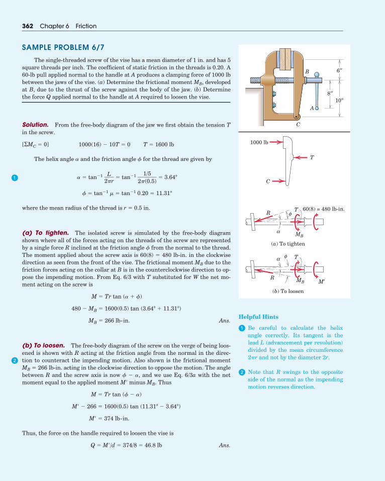
The single-threaded screw of the vise has a mean diameter of 1 in. and has 5square threads per inch. The coefficient of static friction in the threads is 0.20. A60-lb pull applied normal to the handle at A produces a clamping force of 1000 lbbetween the jaws of the vise. (a) Determine the frictional moment MB, developedat B, due to the thrust of the screw against the body of the jaw. (b) Determinethe force Q applied normal to the handle at A required to loosen the vise.
Solution. From the free-body diagram of the jaw we first obtain the tension Tin the screw.
The helix angle � and the friction angle � for the thread are given by
where the mean radius of the thread is r � 0.5 in.
(a) To tighten. The isolated screw is simulated by the free-body diagramshown where all of the forces acting on the threads of the screw are representedby a single force R inclined at the friction angle � from the normal to the thread.The moment applied about the screw axis is 60(8) � 480 lb-in. in the clockwisedirection as seen from the front of the vise. The frictional moment MB due to thefriction forces acting on the collar at B is in the counterclockwise direction to op-pose the impending motion. From Eq. 6/3 with T substituted for W the net mo-ment acting on the screw is
Ans.
(b) To loosen. The free-body diagram of the screw on the verge of being loos-ened is shown with R acting at the friction angle from the normal in the direc-tion to counteract the impending motion. Also shown is the frictional momentMB � 266 lb-in. acting in the clockwise direction to oppose the motion. The anglebetween R and the screw axis is now � � �, and we use Eq. 6/3a with the netmoment equal to the applied moment M� minus MB. Thus
Thus, the force on the handle required to loosen the vise is
Ans.Q � M�/d � 374/8 � 46.8 lb
M� � 374 lb-in.
M� � 266 � 1600(0.5) tan (11.31� � 3.64�)
M � Tr tan (� � �)
MB � 266 lb-in.
480 � MB � 1600(0.5) tan (3.64� � 11.31�)
M � Tr tan (� � �)
� � tan�1 � � tan�1 0.20 � 11.31�
� � tan�1 L2�r
� tan�1 1/52�(0.5)
� 3.64�
1000(16) � 10T � 0 T � 1600 lb[ΣMC � 0]
A
B
C
8′′10′′
6′′
1000 lb
C
T
α
φR60(8) = 480 lb-in.T
MB
(a) To tighten
α φ
R
T
MB M′
(b) To loosen
�
�
Helpful Hints
� Be careful to calculate the helixangle correctly. Its tangent is thelead L (advancement per revolution)divided by the mean circumference2�r and not by the diameter 2r.
� Note that R swings to the oppositeside of the normal as the impendingmotion reverses direction.

6/55 The device shown is used for coarse adjustment of theheight of an experimental apparatus without a changein its horizontal position. Because of the slipjoint at A,turning the screw does not rotate the cylindrical legabove A. The mean diameter of the thread is in. andthe coefficient of friction is 0.15. For a conservativedesign which neglects friction at the slipjoint, whatshould be the minimum number N of threads per inchto ensure that the single-threaded screw does not turnby itself under the weight of the apparatus?
Problem 6/55
6/56 The doorstop is inserted with a rightward hori-zontal force of 30 lb. If the coefficient of staticfriction for all surfaces is , determine thevalues and of the normal forces on the upperand lower faces of the doorstop. With the giveninformation, can you determine the force P requiredto extract the doorstop?
Problem 6/56
10∞
Door
30 lb
10°
NLNU
�s � 0.20
10�
P
A
38
Article 6/5 Problems 363
PROBLEMS(Unless otherwise instructed, neglect the weights of thewedges and screws in the problems which follow.)
Introductory Problems
6/53 The wedge is driven under the spring-loadedwheel whose supporting strut C is fixed. Determinethe minimum coefficient of static friction forwhich the wedge will remain in place. Neglect allfriction associated with the wheel.
Problem 6/53
6/54 In wood-frame construction, two shims are fre-quently used to fill the gap between the framing Sand the thinner window/door jamb D. The membersS and D are shown in cross section in the figure. Forthe shims shown, determine the minimum neces-sary coefficient of static friction necessary so thatthe shims will remain in place.
Problem 6/54
DS
3°
3°
3�
10°
C
sμ
�s
10�

364 Chapter 6 Friction
6/57 The elements of a deodorant dispenser are shown inthe figure. To advance the deodorant D, the knob Cis turned. The threaded shaft engages the threadsin the movable deodorant base A; the shaft has nothreads at the fixed support B. The 6-mm-diameterdouble square thread has a lead of 5 mm. Determinethe coefficient of static friction for which the de-odorant will not retract under the action of the force P.Neglect friction at B.
Problem 6/57
6/58 A 1600-kg rear-wheel-drive car is being driven upthe ramp at a slow steady speed. Determine theminimum coefficient of static friction for whichthe portable ramp will not slip forward. Also deter-mine the required friction force at each reardrive wheel.
Problem 6/58
1070mm
315 mm
500 mm
2545 mm
150 mm
500 mm
Bsμ
380 mmA
G
FA
�s
P
D
A
B
C
�s
6/59 Determine the force P required to force the wedge under the 90-kg uniform crate which restsagainst the small stop at A. The coefficient of fric-tion for all surfaces is 0.40.
Problem 6/59
Representative Problems
6/60 The two wedges shown are used to adjust the po-sition of the column under a vertical load of 5 kN.Determine the magnitude of the forces P requiredto raise the column if the coefficient of friction forall surfaces is 0.40.
Problem 6/60
6/61 If the loaded column of Prob. 6/60 is to be lowered,calculate the horizontal forces P required to with-draw the wedges.
�
P P
5 kN
5° 5°
5�
P
0.7 m
A
1.2 m5°
10°
10°90 kg
10�
Problem 6/64
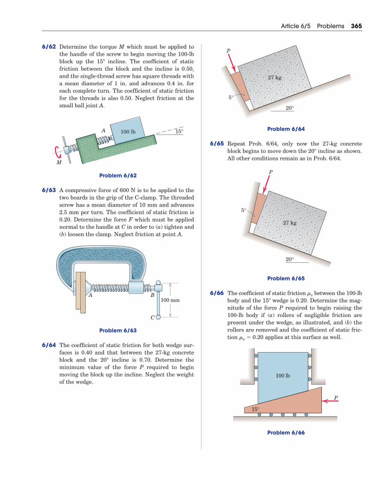
6/65 Repeat Prob. 6/64, only now the 27-kg concreteblock begins to move down the incline as shown.All other conditions remain as in Prob. 6/64.
Problem 6/65
6/66 The coefficient of static friction between the 100-lbbody and the wedge is 0.20. Determine the mag-nitude of the force P required to begin raising the100-lb body if (a) rollers of negligible friction arepresent under the wedge, as illustrated, and (b) therollers are removed and the coefficient of static fric-tion applies at this surface as well.
Problem 6/66
15°
100 lb
P
�s � 0.20
15�
�s
P
20°
5°
27 kg
20�
P
20°
5°
27 kg
Article 6/5 Problems 365
6/62 Determine the torque M which must be applied tothe handle of the screw to begin moving the 100-lbblock up the incline. The coefficient of staticfriction between the block and the incline is 0.50,and the single-thread screw has square threads witha mean diameter of 1 in. and advances 0.4 in. foreach complete turn. The coefficient of static frictionfor the threads is also 0.50. Neglect friction at thesmall ball joint A.
Problem 6/62
6/63 A compressive force of 600 N is to be applied to thetwo boards in the grip of the C-clamp. The threadedscrew has a mean diameter of 10 mm and advances2.5 mm per turn. The coefficient of static friction is0.20. Determine the force F which must be appliednormal to the handle at C in order to (a) tighten and(b) loosen the clamp. Neglect friction at point A.
Problem 6/63
6/64 The coefficient of static friction for both wedge sur-faces is 0.40 and that between the 27-kg concreteblock and the incline is 0.70. Determine theminimum value of the force P required to beginmoving the block up the incline. Neglect the weightof the wedge.
20�
A B
C
100 mm
M
A 15°100 lb
15�
366 Chapter 6 Friction
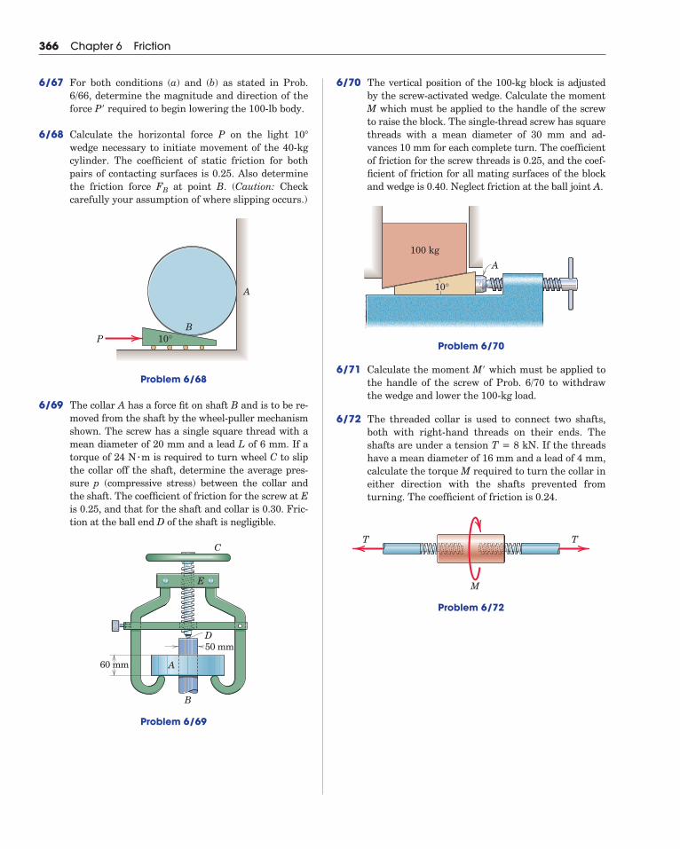
6/67 For both conditions (a) and (b) as stated in Prob.6/66, determine the magnitude and direction of theforce P required to begin lowering the 100-lb body.
6/68 Calculate the horizontal force P on the light wedge necessary to initiate movement of the 40-kgcylinder. The coefficient of static friction for bothpairs of contacting surfaces is 0.25. Also determinethe friction force at point B. (Caution: Checkcarefully your assumption of where slipping occurs.)
Problem 6/68
6/69 The collar A has a force fit on shaft B and is to be re-moved from the shaft by the wheel-puller mechanismshown. The screw has a single square thread with amean diameter of 20 mm and a lead L of 6 mm. If atorque of 24 N m is required to turn wheel C to slipthe collar off the shaft, determine the average pres-sure p (compressive stress) between the collar andthe shaft. The coefficient of friction for the screw at Eis 0.25, and that for the shaft and collar is 0.30. Fric-tion at the ball end D of the shaft is negligible.
Problem 6/69
60 mm
50 mm
C
E
D
A
B
�
P 10°B
A
FB
10�
�
6/70 The vertical position of the 100-kg block is adjustedby the screw-activated wedge. Calculate the momentM which must be applied to the handle of the screwto raise the block. The single-thread screw has squarethreads with a mean diameter of 30 mm and ad-vances 10 mm for each complete turn. The coefficientof friction for the screw threads is 0.25, and the coef-ficient of friction for all mating surfaces of the blockand wedge is 0.40. Neglect friction at the ball joint A.
Problem 6/70
6/71 Calculate the moment M which must be applied tothe handle of the screw of Prob. 6/70 to withdrawthe wedge and lower the 100-kg load.
6/72 The threaded collar is used to connect two shafts,both with right-hand threads on their ends. Theshafts are under a tension T = 8 kN. If the threadshave a mean diameter of 16 mm and a lead of 4 mm,calculate the torque M required to turn the collar ineither direction with the shafts prevented fromturning. The coefficient of friction is 0.24.
Problem 6/72
M
TT
�
100 kg
10°
A

Article 6/5 Problems 367
6/73 The jack shown is designed to lift small unit-bodycars. The screw is threaded into the collar pivoted atB, and the shaft turns in a ball thrust bearing at A.The thread has a mean diameter of 10 mm and alead (advancement per revolution) of 2 mm. The coefficient of friction for the threads is 0.20. Deter-mine the force P normal to the handle at D required(a) to raise a mass of 500 kg from the positionshown and (b) to lower the load from the same posi-tion. Neglect friction in the pivot and bearing at A.
Problem 6/73
�
150 mm45°45°
100 mm
80 mm
D
C
BA
6/74 The tapered pin is forced into a mating taperedhole in the fixed block with a force P = 400 N. If theforce required to remove the pin (with P = 0) is P =300 N, determine the coefficient of friction betweenthe pin and the surface of the hole. (Hint: The pres-sure (stress) normal to the tapered pin surface re-mains unchanged until the pin actually moves. Thedistributed forces over the surface of the pin may bereplaced by an equivalent single resultant force.)
Problem 6/74
2°
P′
P
�
2�

6/6 Journal BearingsA journal bearing is one which gives lateral support to a shaft in
contrast to axial or thrust support. For dry bearings and for manypartially lubricated bearings we may apply the principles of dry fric-tion. These principles provide a satisfactory approximation for designpurposes.
A dry or partially lubricated journal bearing with contact or nearcontact between the shaft and the bearing is shown in Fig. 6/8, wherethe clearance between the shaft and bearing is greatly exaggerated toclarify the action. As the shaft begins to turn in the direction shown, itwill roll up the inner surface of the bearing until it slips. Here it will re-main in a more or less fixed position during rotation. The torque M re-quired to maintain rotation and the radial load L on the shaft will cause
368 Chapter 6 Friction
a reaction R at the contact point A. For vertical equilibrium R mustequal L but will not be collinear with it. Thus, R will be tangent to asmall circle of radius rƒ called the friction circle. The angle between Rand its normal component N is the friction angle �. Equating the sum ofthe moments about A to zero gives
(6/4)
For a small coefficient of friction, the angle � is small, and thesine and tangent may be interchanged with only small error. Since � �
tan �, a good approximation to the torque is
(6/4a)
This relation gives the amount of torque or moment which must be ap-plied to the shaft to overcome friction for a dry or partially lubricatedjournal bearing.
M � �Lr
M � Lrƒ � Lr sin �
Shaft
Bearing
L
M
NR
F
A
Orƒ
r
Figure 6/8

6/7 Thrust Bearings; Disk FrictionFriction between circular surfaces under distributed normal pres-
sure occurs in pivot bearings, clutch plates, and disk brakes. To examinethese applications, we consider the two flat circular disks shown in Fig.6/9. Their shafts are mounted in bearings (not shown) so that they canbe brought into contact under the axial force P. The maximum torquewhich this clutch can transmit is equal to the torque M required to slipone disk against the other. If p is the normal pressure at any locationbetween the plates, the frictional force acting on an elemental area is �p dA, where � is the friction coefficient and dA is the area r dr d� ofthe element. The moment of this elemental friction force about the shaftaxis is �pr dA, and the total moment becomes
where we evaluate the integral over the area of the disk. To carry outthis integration, we must know the variation of � and p with r.
M � � �pr dA
Article 6/7 Thrust Bearings; Disk Friction 369
dθ
R
p dAμ dr
P P
M
M
r
Figure 6/9
In the following examples we will assume that � is constant. Fur-thermore, if the surfaces are new, flat, and well supported, it is reason-able to assume that the pressure p is uniform over the entire surface sothat �R2p � P. Substituting the constant value of p in the expressionfor M gives
(6/5)
We may interpret this result as equivalent to the moment due to a fric-tion force �P acting at a distance from the shaft center.
If the friction disks are rings, as in the collar bearing shown in Fig.6/10, the limits of integration are the inside and outside radii Ri and Ro,respectively, and the frictional torque becomes
(6/5a)
After the initial wearing-in period is over, the surfaces retain theirnew relative shape and further wear is therefore constant over the sur-face. This wear depends on both the circumferential distance traveled
M �23
�PRo
3 � Ri
3
Ro
2 � Ri
2
23R
M ��P�R2 �
2�
0�R
0r2 dr d� �
23
�PR

and the pressure p. Since the distance traveled is proportional to r, theexpression rp � K may be written, where K is a constant. The value of Kis determined from the equilibrium condition for the axial forces, whichgives
With pr � K � P/(2�R), we may write the expression for M as
which becomes
(6/6)
The frictional moment for worn-in plates is, therefore, only or as much as for new surfaces. If the friction disks are rings of inside ra-dius Ri and outside radius Ro, substitution of these limits gives for thefrictional torque for worn-in surfaces
(6/6a)
You should be prepared to deal with other disk-friction problemswhere the pressure p is some other function of r.
M �12
�P(Ro � Ri)
34(12)/(23),
M �12
�PR
M � � �pr dA ��P
2�R�2�
0�R
0r dr d�
P � � p dA � K �2�
0�R
0dr d� � 2�KR
370 Chapter 6 Friction
2Ri 2RoP
M
Figure 6/10
A typical automotive disk brake
© C
ou
rte
sy o
f G
en
era
l Mo
tors
/Zu
ma
Pre
ss

SAMPLE PROBLEM 6/8
The bell crank fits over a 100-mm-diameter shaft which is fixed and cannotrotate. The horizontal force T is applied to maintain equilibrium of the crankunder the action of the vertical force P � 100 N. Determine the maximum andminimum values which T may have without causing the crank to rotate in eitherdirection. The coefficient of static friction � between the shaft and the bearingsurface of the crank is 0.20.
Solution. Impending rotation occurs when the reaction R of the fixed shaft onthe bell crank makes an angle � � tan�1 � with the normal to the bearing sur-face and is, therefore, tangent to the friction circle. Also, equilibrium requiresthat the three forces acting on the crank be concurrent at point C. These factsare shown in the free-body diagrams for the two cases of impending motion.
The following calculations are needed:
(a) Impending counterclockwise motion. The equilibrium triangle of forcesis drawn and gives
Ans.
(b) Impending clockwise motion. The equilibrium triangle of forces for thiscase gives
Ans.T2 � Tmin � 136.2 N
T2 � P cot (� � �) � 100 cot (33.7� � 2.60�)
T1 � Tmax � 165.8 N
T1 � P cot (� � �) � 100 cot (33.7� � 2.60�)
Angle � � sin�1rƒ
OC� sin�1 9.81
�(120)2 � (180)2� 2.60�
Angle � � tan�1 120180
� 33.7�
Radius of friction circle rƒ � r sin � � 50 sin 11.31� � 9.81 mm
Friction angle � � tan�1 � � tan�1 0.20 � 11.31�
Article 6/7 Thrust Bearings; Disk Friction 371
P = 100 N
180 mm
120 mm
T
100 mm
O
P = 100 N
P
O
T1
R1
R1
T1
–
C
r
rƒ
(a) Counterclockwise motion impends
P = 100 N
PR2
T2
+
(b) Clockwise motion impends
O
T2
R2
C
r
rƒ

6/77 Circular disk A is placed on top of disk B and is sub-jected to a compressive force of 80 lb. The diametersof A and B are 9 in. and 12 in., respectively, and thepressure under each disk is constant over its sur-face. If the coefficient of friction between A and B is0.40, determine the couple M which will cause A toslip on B. Also, what is the minimum coefficient offriction between B and the supporting surface Cwhich will prevent B from rotating?
Problem 6/77
6/78 Determine the tension T in the cable to raise the800-kg load if the coefficient of friction for the 30-mmbearing is 0.25. Also find the tension in the sta-tionary section of the cable. The mass of the cableand pulley is small and may be neglected.
Problem 6/78
300mm
30mm
T
T0
800kg
T0
AABB
C
M
80 lb
�
372 Chapter 6 Friction
PROBLEMSIntroductory Problems
6/75 A torque M of 1510 N m must be applied to the 50-mm-diameter shaft of the hoisting drum to raisethe 500-kg load at constant speed. The drum andshaft together have a mass of 100 kg. Calculate thecoefficient of friction for the bearing.
Problem 6/75
6/76 The two flywheels are mounted on a common shaftwhich is supported by a journal bearing betweenthem. Each flywheel has a mass of 40 kg, and thediameter of the shaft is 40 mm. If a 3-N m couple Mon the shaft is required to maintain rotation of theflywheels and shaft at a constant low speed, com-pute (a) the coefficient of friction in the bearing and(b) the radius rƒ of the friction circle.
Problem 6/76
M
�
500 kg
50mm
300mm
M
�
�

6/79 Calculate the tension T required to lower the 800-kgload described in Prob. 6/78. Also find .
6/80 The 20-kg steel ring A with inside and outside radiiof 50 mm and 60 mm, respectively, rests on a fixedhorizontal shaft of 40-mm radius. If a downwardforce P = 150 N applied to the periphery of the ringis just sufficient to cause the ring to slip, calculatethe coefficient of friction and the angle .
Problem 6/80
Representative Problems
6/81 The weight of the drum D and its cable is 100 lb,and the coefficient of friction for the bearing is0.20. Determine the force P required to raise the 80-lb cylinder if the bearing friction is (a) neglectedand (b) included in the analysis. The weight of theshaft is negligible.
Problem 6/81
16′′
2′′
10′′
80 lb
DP
�
40mm
50mm
60 mm
BG
A
P
θ
��
T0
Article 6/7 Problems 373
6/82 Determine the force P required to lower the 80-lbcylinder of Prob. 6/81. Compare your answer withthe stated results of that problem. Is the no-frictionvalue of P equal to the average of the forces re-quired to raise and lower the cylinder?
6/83 The axial section of the two mating circular disksis shown. Derive the expression for the torque M re-quired to turn the upper disk on the fixed lower oneif the pressure p between the disks follows the rela-tion , where k is a constant to be deter-mined. The coefficient of friction is constant overthe entire surface.
Problem 6/83
Rotating
Fixed
ri
M
L
ro
�
p � k/r2

6/87 The telephone-cable reel has a mass of 250 kg and ismounted on an 80-mm-diameter shaft. If the coeffi-cient of friction between the shaft and its bearing is0.30, calculate the horizontal tension T required toturn the reel.
Problem 6/87
6/88 The front wheels of an experimental rear-drive ve-hicle have a radius of 300 mm and are designedwith disk-type brakes consisting of a ring A withoutside and inside radii of 150 mm and 75 mm, re-spectively. The ring, which does not turn with thewheel, is forced against the wheel disk with a force P.If the pressure between the ring and the wheel diskis uniform over the mating surfaces, compute thefriction force F between each front tire and the hor-izontal road for an axial force P = 1 kN when thevehicle is powered at constant speed with thewheels turning. The coefficient of friction betweenthe disk and ring is 0.35.
Problem 6/88
A
P P75 mm
300 mm
150 mm
500 mm80 mm
T
374 Chapter 6 Friction
6/84 The two pulleys are fastened together and are used tohoist the cylinder of mass m. The fraction k can varyfrom near zero to one. Derive an expression for thetension T required to raise the cylinder at a steady speed if the coefficient of friction for thebearing of radius is , a small enough value to per-mit the substitution of for , where is thefriction angle. The mass of the pulley unit is .Evaluate your expression for T if m = 50 kg,
, and.
Problem 6/84
6/85 Repeat Prob. 6/84 for the case of lowering the cylin-der of mass m at a steady speed.
6/86 An end of the thin board is being sanded by the disksander under application of the force P. If the effec-tive coefficient of kinetic friction is and if the pres-sure is essentially constant over the board end,determine the moment M which must be applied bythe motor in order to rotate the disk at a constantangular speed. The board end is centered along theradius of the disk.
Problem 6/86
�
kr
r
T
m
� � 0.15r0 � 25 mm,k �
12r � 0.3 m,m0 � 30 kg,
m0
�sin ��
�r0
R/4R/2
R/4
R
P

6/89 An automobile disk brake consists of a flat-facedrotor and a caliper which contains a disk pad oneach side of the rotor. For equal forces P behind thetwo pads with the pressure p uniform over the pad,show that the moment applied to the hub is inde-pendent of the angular span of the pads. Wouldpressure variation with change the moment?
Problem 6/89
6/90 The pulley system shown is used to hoist the 200-kgblock. The diameter of the bearing for the upperpulley is 20 mm, and that for the lower pulley is 12 mm. For a coefficient of friction for bothbearings, calculate the tensions T, , and in thethree cables if the block is being raised slowly.
Problem 6/90
6/91 Calculate the tensions T, , and for Prob. 6/90 ifthe block is being lowered slowly.
T2T1
180 mm
90 mm
200 kg
T1T2
T
T2T1
� � 0.25
RoRi
β
θ
�
�
Article 6/7 Problems 375
6/92 For the flat sanding disk of radius a, the pressure pdeveloped between the disk and the sanded surfacedecreases linearly with r from a value at the cen-ter to at r = a. If the coefficient of friction is ,derive the expression for the torque M required toturn the shaft under an axial force L.
Problem 6/92
6/93 In addition to the radial pressure variation of Prob. 6/92, assume that the coefficient of friction decreases linearly with r from a value at thecenter to at r = a. Derive an expression for thetorque M required to turn the shaft under an axialload L and compare with the stated result forProb. 6/92.
6/94 Each of the four wheels of the vehicle weighs 40 lband is mounted on a 4-in.-diameter journal (shaft).The total weight of the vehicle is 960 lb, includingwheels, and is distributed equally on all four wheels.If a force P = 16 lb is required to keep the vehiclerolling at a constant low speed on a horizontal sur-face, calculate the coefficient of friction which existsin the wheel bearings. (Hint: Draw a complete free-body diagram of one wheel.)
Problem 6/94
P
40″4″
�0 /2�0
�
ap0
p0
p
M
L
r
1––2
�p0 /2p0

6/96 The hemispherical thrust bearing on the end of theshaft supports an axial force P. Derive the expres-sion for the moment M required to rotate the shaftat constant speed if the pressure p is proportional tosin and the coefficient of friction is .
Problem 6/96
r
P
M
α
p
��
376 Chapter 6 Friction
6/95 In the figure is shown a multiple-disk clutch de-signed for marine use. The driving disks A aresplined to the driving shaft B so that they are free toslip along the shaft but must rotate with it. Thedisks C drive the housing D by means of the bolts E,along which they are free to slide. In the clutchshown there are five pairs of friction surfaces.Assume the pressure is uniformly distributed overthe area of the disks and determine the maximumtorque M which can be transmitted if the coefficientof friction is 0.15 and P = 500 N.
Problem 6/95
75 mm
100 mm150 mm 20°
PB
A
DE
C
25 mm
�

6/8 Flexible BeltsThe impending slippage of flexible cables, belts, and ropes over
sheaves and drums is important in the design of belt drives of all types,band brakes, and hoisting rigs.
Figure 6/11a shows a drum subjected to the two belt tensions T1
and T2, the torque M necessary to prevent rotation, and a bearing reac-tion R. With M in the direction shown, T2 is greater than T1. The free-body diagram of an element of the belt of length r d� is shown in part bof the figure. We analyze the forces acting on this differential elementby establishing the equilibrium of the element, in a manner similar tothat used for other variable-force problems. The tension increases fromT at the angle � to T � dT at the angle � � d�. The normal force is a dif-ferential dN, since it acts on a differential element of area. Likewise thefriction force, which must act on the belt in a direction to oppose slip-ping, is a differential and is � dN for impending motion.
Equilibrium in the t-direction gives
or
since the cosine of a differential quantity is unity in the limit. Equilib-rium in the n-direction requires that
or
where we have used the facts that the sine of a differential angle in thelimit equals the angle and that the product of two differentials must beneglected in the limit compared with the first-order differentials re-maining.
Combining the two equilibrium relations gives
Integrating between corresponding limits yields
or
where the ln (T2/T1) is a natural logarithm (base e). Solving for T2 gives
(6/7)T2 � T1e��
lnT2
T1� ��
�T2
T1
dTT
� ��
0� d�
dTT
� � d�
dN � T d�
dN � (T � dT) sin d�2
� T sin d�2
� dN � dT
T cos d�2
� � dN � (T � dT) cos d�2
Article 6/8 Flexible Belts 377
Figure 6/11
T2
T1
β θθd
θθ
d
μ rdNdN
r
M
R
(a)
(b)
T
T + dT
t
n
d––2
θd––2
Just one turn of a line around afixed cylinder can produce a largechange in tension.
© M
ed
ia B
ake
ry

Note that � is the total angle of belt contact and must be expressed inradians. If a rope were wrapped around a drum n times, the angle �
would be 2�n radians. Equation 6/7 holds equally well for a noncircularsection where the total angle of contact is �. This conclusion is evidentfrom the fact that the radius r of the circular drum in Fig. 6/11 does notenter into the equations for the equilibrium of the differential elementof the belt.
The relation expressed by Eq. 6/7 also applies to belt drives whereboth the belt and the pulley are rotating at constant speed. In this casethe equation describes the ratio of belt tensions for slippage or impend-ing slippage. When the speed of rotation becomes large, the belt tends toleave the rim, so Eq. 6/7 involves some error in this case.
6/9 Rolling ResistanceDeformation at the point of contact between a rolling wheel and its
supporting surface introduces a resistance to rolling, which we mentiononly briefly. This resistance is not due to tangential friction forces andtherefore is an entirely different phenomenon from that of dry friction.
To describe rolling resistance, we consider the wheel shown in Fig.6/12 under the action of a load L on the axle and a force P applied at itscenter to produce rolling. The deformation of the wheel and supportingsurfaces as shown is greatly exaggerated. The distribution of pressure pover the area of contact is similar to the distribution shown. The resul-tant R of this distribution acts at some point A and must pass throughthe wheel center for the wheel to be in equilibrium. We find the force Pnecessary to maintain rolling at constant speed by equating the mo-ments of all forces about A to zero. This gives us
where the moment arm of P is taken to be r. The ratio �r � a/r iscalled the coefficient of rolling resistance. This coefficient is the ratio ofresisting force to normal force and thus is analogous to the coefficient of static or kinetic friction. On the other hand, there is no slippage orimpending slippage in the interpretation of �r.
Because the dimension a depends on many factors which are diffi-cult to quantify, a comprehensive theory of rolling resistance is notavailable. The distance a is a function of the elastic and plastic proper-ties of the mating materials, the radius of the wheel, the speed of travel,and the roughness of the surfaces. Some tests indicate that a varies onlyslightly with wheel radius, and thus a is often taken to be independentof the rolling radius. Unfortunately, the quantity a has also been calledthe coefficient of rolling friction in some references. However, a has thedimension of length and therefore is not a dimensionless coefficient inthe usual sense.
P �ar L � �r L
378 Chapter 6 Friction
R
p
a
r
A
L
P
Figure 6/12

SAMPLE PROBLEM 6/9
A flexible cable which supports the 100-kg load is passed over a fixed circu-lar drum and subjected to a force P to maintain equilibrium. The coefficient ofstatic friction � between the cable and the fixed drum is 0.30. (a) For � � 0, de-termine the maximum and minimum values which P may have in order not toraise or lower the load. (b) For P � 500 N, determine the minimum value whichthe angle � may have before the load begins to slip.
Solution. Impending slipping of the cable over the fixed drum is given by Eq.6/7, which is T2/T1 � e��.
(a) With � � 0 the angle of contact is � � �/2 rad. For impending upward mo-tion of the load, T2 � Pmax, T1 � 981 N, and we have
Ans.
For impending downward motion of the load, T2 � 981 N and T1 � Pmin. Thus,
Ans.
(b) With T2 � 981 N and T1 � P � 500 N, Eq. 6/7 gives us
Ans.� � 128.7� � 90� � 38.7�
� � 2.25 rad or � � 2.25�3602� � 128.7�
981/500 � e0.30� 0.30� � ln(981/500) � 0.674
981/Pmin � e0.30(�/2) Pmin � 981/1.602 � 612 N
Pmax/981 � e0.30(�/2) Pmax � 981(1.602) � 1572 N
Article 6/9 Rolling Resistance 379
Or
α
P
100 kg
O
P
981 N(a) = 0α
= /2πβ
O
αP
981 N(b) P = 500 N
β
�
�
�
Helpful Hints
� We are careful to note that � mustbe expressed in radians.
� In our derivation of Eq. 6/7 be cer-tain to note that T2 � T1.
� As was noted in the derivation of Eq.6/7, the radius of the drum does notenter into the calculations. It is onlythe angle of contact and the coeffi-cient of friction which determine thelimiting conditions for impendingmotion of the flexible cable over thecurved surface.

SAMPLE PROBLEM 6/10
Determine the range of mass m over which the system is in static equilib-rium. The coefficient of static friction between the cord and the upper curvedsurface is 0.20, while that between the block and the incline is 0.40. Neglect fric-tion at the pivot O.
Solution. From the FBD of the uniform slender bar, we can determine thetension in the cable at point A.
I. Motion of m impends up the incline.
The tension is the larger of the two tensions associated withthe rough rounded surface. From Eq. 6/7 we have
From the FBD of the block for Case I:
N = 0.766mg
II. Motion of m impends down the incline.
The value is unchanged, but now this is the smaller of the twotensions in Eq. 6/7.
Considering the FBD of the block for Case II, we see that the normal force N isunchanged from Case I.
So the requested range is . Ans.6.16 � m � 28.3 kg
m � 28.3 kgmg � 278 N
�93.5 – 0.4(0.766mg) � mg sin 40� � 0[ΣFx � 0]
T2 � 93.5 NT2 � 73.3e0.20[30� � 40�]�/180�[T2 � T1e�s�]
TA � 73.3 N
m � 6.16 kgmg � 60.5 N
�57.4 � mg sin 40� � 0.40(0.766mg) � 0[ΣFx � 0]
N � mg cos 40� � 0[ΣFy � 0]
T1 � 57.4 N73.3 � T1e0.20[30� � 40�]�/180�[T2 � T1e�s�]
TA � 73.3 N
TA � 73.3 N
� TA �2L3
cos 35� � 9(9.81) �L2
cos 25� � 0[ΣMO � 0]
TA
380 Chapter 6 Friction
r r
d30°
9 kg
25°A
O
m2L/3
L/3
ms = 0.20
ms = 0.40
q = 40°
40°
y
x
T1 = 57.4 N
N
Case I
0.40N
mg
40°x
T2 = 93.5 N
N
Case II
0.40N
mg
A
9(9.81) N
G
TA
Ox
Oy
O25°
35°
L/2
L/6
Helpful Hints
� Only the total angular contact entersEq. 6/7 (as ). So our results are in-dependent of the quantities r and d.
� Re-solve the entire problem if theramp angle were changed to ,with all other given information re-maining constant. Be alert for a sur-prising result!
20��
�
�
�

PROBLEMSIntroductory Problems
6/97 What is the minimum coefficient of friction be-tween the rope and the fixed shaft which will pre-vent the unbalanced cylinders from moving?
Problem 6/97
6/98 Determine the force P required to (a) raise and (b) lower the 40-kg cylinder at a slow steady speed.The coefficient or friction between the cord and itssupporting surface is 0.30.
Problem 6/98
6/99 A force is required to lower the cylinder ata constant slow speed with the cord making turnsaround the fixed shaft. Calculate the coefficient offriction between the cord and the shaft.�
114
P � mg/6
40 kg
P
50 lb
100 lb
�
Article 6/9 Problems 381
Problem 6/99
6/100 A dockworker adjusts a spring line (rope) whichkeeps a ship from drifting alongside a wharf. If heexerts a pull of 200 N on the rope, which has turns around the mooring bit, what force T can hesupport? The coefficient of friction between therope and the cast-steel mooring bit is 0.30.
Problem 6/100
6/101 A 50-kg package is attached to a rope which passesover an irregularly shaped boulder with uniformsurface texture. If a downward force isrequired to lower the package at a constant rate,(a) determine the coefficient of friction betweenthe rope and the boulder. (b) What force P wouldbe required to raise the package at a constant rate?
Problem 6/101
P50 kg
��
P � 70 N
200 NT
114
m
P

6/104 In western movies, cowboys are frequently ob-served hitching their horses by casually windinga few turns of the reins around a horizontal poleand letting the end hang free as shown––noknots! If the freely hanging length of rein weighs2 oz and the number of turns is as shown, whattension T does the horse have to produce in thedirection shown in order to gain freedom? The co-efficient of friction between the reins and woodenpole is 0.70.
Problem 6/104
Representative Problems
6/105 Calculate the horizontal force P required to raisethe 100-kg load. The coefficient of friction betweenthe rope and the fixed bars is 0.40.
Problem 6/105
d
P
100 kg
d
3d—2
30°
382 Chapter 6 Friction
6/102 With what horizontal force P must the worker pullin order to move the 35-kg log up the incline?The coefficient of friction between the log and theincline is 0.60 and that between the rope and theboulder is 0.40.
15�
15°
= 0.60μ
= 0.40μ
Problem 6/102
6/103 A garden hose with a mass of is in fullcontact with the ground from B to C. What is thehorizontal component of the force which the gar-dener must exert in order to pull the hose aroundthe small cylindrical guard at B? The coefficient offriction between the hose and the ground is 0.50,and that between the hose and the cylinder is 0.40.Assume that the hose does not touch the groundbetween A and B.
Problem 6/103
Px
1.2 kg /m
5 m
B
AC

6/106 The vertical consists of a frame, three fixed 8-in.-diameter drums, and six small guide wheels with acombined weight of 50 lb. Determine the minimumweight W necessary to hold the trolley in equilibriumfor any position in its vertical guides. The coeffi-cient of friction between the light cable and thedrums is 0.30.
Problem 6/106
6/107 The 180-lb tree surgeon lowers himself with therope over a horizontal limb of the tree. If the coeffi-cient of friction between the rope and the limb is0.60, compute the force which the man must exerton the rope to let himself down slowly.
Problem 6/107
10′′
10′′
8′′
W
Article 6/9 Problems 383
6/108 The uniform crate of mass m is supported by thetension in the flexible strap passing under it. For agiven position , determine an expression for thetension T on the strap needed to begin (a) raisingthe crate and (b) lowering the crate if the coeffi-cient of friction between the strap and the crate is .Neglect any friction between the crate and its verti-cal guides.
Problem 6/108
6/109 The positions of shafts A and C are fixed while thatof shaft B can be varied via the vertical slot and thelocking bolt. If the coefficient of static friction is at all interfaces, determine the dependence of T onthe coordinate y, where T is the tension required tobegin to lift the cylinder of mass m. All shafts arefixed against rotation.
Problem 6/109
6/110 Repeat Prob. 6/109, only now the coefficients of sta-tic friction are as follows: 0.60 at A and C and 0.20at B. Plot as a function of y for ,where r is the common radius of all three shafts.What are the limiting values of for andfor large values of y?
y � 0T/mg
0 � y � 10rT/mg
r
3r
y
3r
r
r
C
B
A
mT
�
θ θ T
�
�
*

6/113 For the design of the band brake shown, find thecouple M required to turn the pipe in the V-blockagainst the action of the flexible band. A force
lb is applied to the lever, which is pivotedabout O. The coefficient of friction between theband and the pipe is 0.30, and that between thepipe and the block is 0.40. The weights of the partsare negligible.
Problem 6/113
6/114 Shown in the figure is the design of a band-typeoil-filter wrench. If the coefficient of friction be-tween the band and the fixed filter is 0.25, deter-mine the minimum value of h which ensures thatthe wrench will not slip on the filter, regardlessof the magnitude of the force P. Neglect the massof the wrench and assume that the effect of thesmall part A is equivalent to that of a band wrapwhich begins at the three-o’clock position andruns clockwise.
Problem 6/114
7 mm26
mm
h
A B
45mm
P
10″
4″30°30°
M
B
A
P
15″
45°
O
P � 25
384 Chapter 6 Friction
6/111 A counterclockwise moment lb-in. is applied to the flywheel. If the coefficient of frictionbetween the band and the wheel is 0.20, computethe minimum force P necessary to prevent thewheel from rotating.
Problem 6/111
6/112 The endless belt of an escalator passes aroundidler drum A and is driven by a torque M appliedto drum B. Belt tension is adjusted by a turn-buckle at C, which produces an initial tension of1000 lb in each side of the belt when the escalatoris unloaded. For the design of this system calcu-late the minimum coefficient of friction betweendrum B and the belt to prevent slipping if the escalator handles 30 people uniformly distributedalong the belt and averaging 150 lb each. (Note: Itcan be shown that the increase in belt tension onthe upper side of drum B and the decrease in belttension at the lower drum A are each equal to halfthe component of the combined passenger weightalong the incline.)
Problem 6/112
�
P
O
26′′5′′
18′′
M
M � 1500
20′
50′C
A
B
M

Article 6/9 Problems 385
6/115 Determine the range of cylinder weights W forwhich the system is in equilibrium. The coefficientof friction between the 100-lb block and the inclineis 0.20 and that between the cord and cylindricalsupport surface is 0.30.
Problem 6/115
6/116 The cylinder of mass m is attached to the ring A,which is suspended by the cable which passesover the pulley, as shown in part a of the figure.A couple M applied to the pulley turns it untilslipping of the cable on the pulley occurs at theposition , shown in part b of the figure.Calculate the coefficient of friction betweenthe cable and the pulley.
Problem 6/116
6/117 The uniform 3-m beam is suspended by the cablewhich passes over the large pulley. A locking pin atA prevents rotation of the pulley. If the coefficientof friction between the cable and the pulley is 0.25,determine the minimum value of x for which thecable will not slip on the pulley.
AA
90° 90°
mm
θ
(a) (b)
M
�
� � 20�
= 0.30μ
= 0.20μ
20°
100 lb
W
Problem 6/117
6/118 A device designed for lowering a person in a slingdown a rope at a constant controlled rate is shown in the figure. The rope passes around a central shaftfixed to the frame and leads freely out of the lowercollar. The number of turns is adjusted by turningthe lower collar, which winds or unwinds the ropearound the shaft. Entrance of the rope into theupper collar at A is equivalent to of a turn, andpassage around the corner at B is also equivalentto of a turn. Friction of the rope through thestraight portions of the collars averages 10 N foreach collar. If three complete turns around the shaft,in addition to the corner turns, are required for a 75-kg man to lower himself at a constant rate with-out exerting a pull on the free end of the rope, calcu-late the coefficient of friction between the ropeand the contact surfaces of the device. Neglect thesmall helix angle of the rope around the shafts.
Problem 6/118
L
L
L
A
B
�
14
14
3 m
1 m x
A
O

386 Chapter 6 Friction
6/119 Replace the flat belt and pulley of Fig. by a V-belt and matching grooved pulley as indicated bythe cross-sectional view accompanying this prob-lem. Derive the relation among the belt tensions,the angle of contact, and the coefficient of frictionfor the V-belt when slipping impends. A V-belt de-sign with would be equivalent to increasingthe coefficient of friction for a flat belt of the samematerial by what factor n?
Problem 6/119
α
V-beltcross section
� � 35�
6 /11 6/120 The chain has a mass per unit length and a length. For a coefficient of friction between the
chain and its quarter-circular guide, derive an ex-pression for the tension T required to initiate mo-tion upward along the guide in the vertical plane.(Hint: Obtain the equilibrium equations for a differ-ential element of the chain and reduce them to the form , which is a first-order,linear, nonhomogeneous equation whose solutiontakes the standard form
where C and K are constants.)
Problem 6/120
T
r
T � Ce�K� � e�K��eK� f(�) d�
dT/d� � KT � f(�)
��r/2��
6/10 Chapter ReviewIn our study of friction we have concentrated on dry or Coulomb
friction where a simple mechanical model of surface irregularities be-tween the contacting bodies, Fig. 6/1, explains the phenomenon ade-quately for most engineering purposes. This model helps to visualize thethree types of dry-friction problems which are encountered in practice.These problem types are:
1. Static friction of less than the maximum possible value and deter-mined by the equations of equilibrium. (This usually requires acheck to see that F � �sN.)
2. Limiting static friction with impending motion (F � �sN ).
3. Kinetic friction where sliding motion occurs between contactingsurfaces (F � �kN ).
Keep in mind the following when solving dry-friction problems:
1. A coefficient of friction applies to a given pair of mating surfaces. Itis meaningless to speak of a coefficient of friction for a single surface.
2. The coefficient of static friction �s for a given pair of surfaces isusually slightly greater than the kinetic coefficient �k.
3. The friction force which acts on a body is always in the direction tooppose the slipping of the body which takes place or the slippingwhich would take place in the absence of friction.
4. When friction forces are distributed over a surface or along a line,we select a representative element of the surface or line and evalu-ate the force and moment effects of the elemental friction force act-ing on the element. We then integrate these effects over the entiresurface or line.
5. Friction coefficients vary considerably, depending on the exact con-dition of the mating surfaces. Computing coefficients of friction tothree significant figures represents an accuracy which cannot easilybe duplicated by experiment. When cited, such values are includedfor purposes of computational check only. For design computationsin engineering practice, any handbook value for a coefficient of sta-tic or kinetic friction must be viewed as an approximation.
Other forms of friction mentioned in the introductory article of thechapter are important in engineering. Problems which involve fluid fric-tion, for example, are among the most important of the friction prob-lems encountered in engineering, and are studied in the subject of fluidmechanics.
Article 6/10 Chapter Review 387

388 Chapter 6 Friction
6/124 The figure shows a jam cleat designed for a sailboatwhere the large friction forces developed by thecams prevent the rope from slipping. Determinethe force R supported by each cam bearing for the900-N rope tension. The coefficient of static frictionbetween the rope and the cams is 0.80.
Problem 6/124
6/125 The design of the cam-lock vise provides a quickpositive clamping action with a friction coefficientbetween the cam and the movable jaw A of 0.30. (a) As the cam and lever are rotating clockwise approaching the locking position shown with
, determine the clamping force C. (b) WithP removed, find the friction force F in the lockingposition. (c) Determine the force P , opposite from P,required to release the clamp.
Problem 6/125
6/126 Three boxes are placed on the incline in contact witheach other and released from rest. The coefficients ofstatic friction under boxes A, B, and C are 0.30, 0.20,and 0.35, respectively. Describe what happens.
Problem 6/126
20 lbA
B C40 lb 30 lb
s = 0.30μ0.20
0.35
15°
10″
2″
P
A
1—2″
O
�
P � 30 lb
900 N
80mm
20 mm
REVIEW PROBLEMS
6/121 A 100-lb block is placed on a incline and re-leased from rest. The coefficient of static frictionbetween the block and the incline is 0.30. (a) Deter-mine the maximum and minimum values of the ini-tial tension T in the spring for which the block willnot slip when released. (b) Calculate the frictionforce F on the block if .
Problem 6/121
6/122 The circular cylinder weighs 50 lb and is held by acord fixed to its periphery at B and to the ground at A. If the coefficient of static friction is 0.60, calcu-late the force P required to cause the cylinder to slip.
Problem 6/122
6/123 The homogeneous disk of mass m is resting on theright-angled supporting surfaces shown. The ten-sion P in the cord is very gradually increased fromzero. If the friction at both A and B is characterizedby , what happens first––does the homo-geneous disk slip in place or does it begin to roll upthe incline? Determine the value of P at which thisfirst movement occurs.
Problem 6/123
s = 0.25μ
30°
P
AB
�s � 0.25
B
P
60° A
s = 0.60μ
100 lb
s = 0.30μ
30°
T � 40 lb
30�

Article 6/10 Review Problems 389
6/127 A 500-kg log is being steadily pulled up the inclineby means of the cable attached to the winch on thetruck. If the coefficient of kinetic friction is 0.80 be-tween the log and the incline and 0.50 between thecable and rock, determine the tension T which mustbe developed by the winch.
6/130 Under the action of the applied couple M the 25-kgcylinder bears against the roller A, which is free toturn. If the coefficients of static and kinetic frictionbetween the cylinder and the horizontal surface are0.50 and 0.40, respectively, determine the frictionforce F acting on the cylinder if (a)and (b) .
Problem 6/130
6/131 The screw of the small press has a mean diameterof 25 mm and has a single square thread with alead of 8 mm. The flat thrust bearing at A isshown in the enlarged view and has surfaceswhich are well worn. If the coefficient of frictionfor both the threads and the bearing at A is 0.25,calculate the design torque M on the handwheelrequired (a) to produce a compressive force of 4 kN and (b) to loosen the press from the 4-kNcompression.
Problem 6/131
A
25mm
4 mm
20 mmA
M A
30°100 mm
150mm
M � 40 N � mM � 20 N � m
25° 15°
Problem 6/127
6/128 Calculate the torque M which the engine of thepickup truck must supply to the rear axle to rollthe front wheels over the curbing from a rest posi-tion if the rear wheels do not slip. Determine theminimum effective coefficient of friction at the rearwheels to prevent slipping. The mass of the loadedtruck with mass center at G is 1900 kg.
Problem 6/128
6/129 The 4600-lb lathe with mass center at G is posi-tioned with the aid of the steel wedge. Determinethe horizontal force P required to remove the wedgeif the coefficient of friction for all contacting sur-faces is 0.30. Also show that no horizontal move-ment of the lathe takes places.
Problem 6/129
G
B PA
36"
92"
5°
5�
1600 mm 1200 mm
G
130 mm
650 mm

390 Chapter 6 Friction
6/134 The bar clamp is being used to clamp two boards together while the glue between them cures. Whattorque M must be applied to the handle of thescrew in order to produce an 80-lb compression be-tween the boards? The -in.-diameter single-threadscrew has 12 square threads per inch, and the effective coefficient of friction is 0.20. Neglect anyfriction in the pivot contact at C. What torque M isrequired to loosen the clamp?
Problem 6/134
6/135 The detent mechanism consists of the spring-loadedplunger with a spherical end, which is designed toposition the horizontal bar by engaging the spacednotches. If the spring exerts a force of 40 N on theplunger in the position shown and a force is required to move the detent bar against theplunger, calculate the coefficient of friction betweenthe plunger and the detent. It is known from ear-lier tests that the coefficient of friction between thelight bar and the horizontal surface is 0.30. Assumethat the plunger is well lubricated and accuratelyfitted so that the friction between it and its guide isnegligible.
Problem 6/135
60° 60° P
P � 60 N
C
M
�
38
6/132 The small roller of the uniform slender rod restsagainst the vertical surface at A while therounded end at B rests on the platform which isslowly pivoted downward beginning from thehorizontal position shown. If the bar begins toslip when , determine the coefficient ofstatic friction between the bar and the platform.Neglect friction in the roller and the small thick-ness of the platform.
Problem 6/132
6/133 Determine the range of mass m over which the sys-tem is in equilibrium (a) if the coefficient of staticfriction is 0.20 at all three fixed shafts and (b) if thecoefficient of static friction associated with shaft Bis increased to 0.50.
Problem 6/133
C
A
B
2 kg
m
O
A
B
l
2l
θ
�s
� � 25�

Article 6/10 Review Problems 391
6/136 Determine the range of cylinder mass m for whichthe system is in equilibrium. The coefficient of fric-tion between the 50-kg block and the incline is 0.15and that between the cord and cylindrical supportis 0.25.
Problem 6/136
6/137 The elements of a rolling mill are shown here. Inthe design of the roller spacing, determine the max-imum slab thickness b so that the slab will enterthe rollers by means of friction alone if the coeffi-cient of kinetic friction is . Assume that issmall compared with d.
Problem 6/137
a
d
d
b
(b � a)�k
= 0.25μ
= 0.15μ
20°
50 kg
m
6/138 The cylinder weighs 80 lb and the attached uniformslender bar has an unknown weight W. The unit re-mains in static equilibrium for values of the angle ranging up to but slips if exceeds . If thecoefficient of static friction is known to be 0.30, de-termine W.
Problem 6/138
6/139 Calculate the couple M applied to the lower of thetwo 20-kg cylinders which will allow them to rollslowly down the incline. The coefficients of staticand kinetic friction for all contacting surfaces are
and .
Problem 6/139
6/140 The 8-kg block is resting on the inclined planewith a coefficient of static friction . Deter-mine the minimum horizontal force P which willcause the block to slip.
Problem 6/140
P
20°
�s � 0.5020�
300 mm dia.
15°
C
B
A
M
�k � 0.50�s � 0.60
40″
12″
60° 60°
W
θ
45��45�
�

392 Chapter 6 Friction
*Computer-Oriented Problems
6/143 Plot the force P required to begin moving the 100-kgcrate up the incline starting from rest at vari-ous values of x from zero to 10 m. Determine theleast possible value of P and the correspondingvalue of x.
Problem 6/143
6/144 The uniform slender bar of Prob. 6/41 is repeatedhere but now the ideal roller at B is removed. Thecoefficient of static friction at A is 0.70 and that atB is 0.50. Determine the maximum value of theangle for which equilibrium is possible.
Problem 6/144
A
R
B
2R
�
P
100 kg
3 m
x
s = 0.40μ10°
10�
6/141 The device shown is designed to prevent clockwiserotation in the horizontal plane of the centralwheel by means of frictional locking of the twosmall rollers. For given values of R and r and for acommon coefficient of friction at all contact sur-faces, determine the range of values of d for whichthe device will operate as described.
Problem 6/141
6/142 A scissors-type jack with a single square threadwhich engages the threaded collar G and turns in aball thrust bearing at D is being designed. Thethread is to have a mean diameter of 10 mm and alead (advancement per revolution) of 3 mm. With acoefficient of friction of 0.20 for the greased threads,(a) calculate the torque M on the screw required toraise a load of 1000 kg from the position shown and(b) calculate the torque M required to lower theload from the same position. Assume that platformAB and line DG will remain horizontal under load.Neglect friction in the bearing at D.
Problem 6/142
A B
L
H C
I
G D
M
45° 45°30°
30°
30°
30°
30°
GI = DI = 160 mm, HI = CI = 80 mm
30°
F E
d
r
R
�
�
�
*
*

Article 6/10 Review Problems 393
6/145 The semicylindrical shell of mass m and radius r isrolled through an angle by the force P which re-mains tangent to its periphery at A as shown. If P is slowly increased, plot the tilt angle as a func-tion of P up to the point of slipping. Determine thetilt angle and the corresponding value for which slipping occurs. The coefficient of staticfriction is 0.30.
Problem 6/145
6/146 The positions of shafts A and C are fixed while thatof shaft B can be varied via the vertical slot and lock-ing bolt. The coefficients of kinetic friction are 0.60at A and C and 0.20 at B. Plot the quantity asa function of y for , where T is the ten-sion required to lift the cylinder of mass m at asteady rate and r is the common radius of all threeshafts. All shafts are fixed against rotation. What arethe limiting values of for and for largevalues of y?
Problem 6/146
r
3r
y
3r
r
r
A
B
C
mT
y � 0T/mg
0 � y � 10rT/mg
P
A
r
= 0.30
θ
sμ
Pmax�max
�
�
6/147 A heavy cable with a mass of 12 kg per meter oflength passes over the two fixed pipes 300 m aparton the same level. One end supports a 1600-kgcylinder. By experiment it is found that a down-ward force P of 60 kN is required to induce slippingof the cable over both pipes at a constant rate. Determine the coefficient of kinetic friction be-tween the cable and the pipes, the maximum ten-sion T in the cable between the pipes, and the sag hin the cable.
Problem 6/147
6/148 The 100-kg load is elevated by the cable whichslides over the fixed drum with a coefficient of fric-tion of 0.50. The cable is secured to the slider Awhich is pulled slowly along its smooth horizontalguide bar by the force P. Plot P as a function of from to and determine its maxi-mum value along with the corresponding angle .Check your plotted value of analytically.
Problem 6/148
100kg
P
A
θ
= 0.50μ
Pmax
�
� � 10�� � 90�
�
300 m
1600 kg
h
P
�k
*
*
*
*

394 Chapter 6 Friction
6/151 The band wrench is useful for loosening and tight-ening such items as the whole-house water filter Eshown. Assume that the teeth of the wrench do notslip on the band at point C and that the band isslack from C to its end D. Determine the minimumcoefficient of static friction for which the bandwill not slip relative to the fixed filter.
Problem 6/151
D
P
AB
OE
C
250 mm
55mm
�
6/149 The uniform slender pole rests against a smallroller at B. End A will not slip on the horizontalsurface if the coefficient of static friction is suffi-ciently large. (a) Determine the required minimumvalue of to prevent slipping for any value of from to and plot versus . Fromthese results find the range of for which the polewill be unstable if . (b) At what angle isthe pole most unstable, and what is the least coeffi-cient of static friction which would be requiredto prevent slipping for this angle?
Problem 6/149
6/150 The device is designed to permit an adjustment to the horizontal tension T in the cable passingaround the two fixed wheels in order to lower themass m. If the coefficient of friction between thecable and the wheel surfaces is 0.40, determine andplot the ratio as a function of in the range
. Also find the value of the shear force Vin the adjusting pin at D in terms of mg for .
Problem 6/150
D
m
r
A
CB
r
O
T
BC = 2r___DO = 3r___
� � 60�
0 � � � 90�
�T/mg
A
L
B
L/2
θ
�s
��s � 0.40�
��s� � 60�� � 0��s
�s
*
**

This page intentionally left blank