Embed Size (px)
Citation preview

508i Hardware Addendum Revision 3.6 - October 07, 2004

System Galaxy 508i Addendum Hardware Manual
2 Document Revision 3.6 - October 07, 2004
This document is an addendum to the System Galaxy Hardware Manual and covers the installation
and setup of the 508i Controller/CPU Board. Information in this document is subject to change without
notice. No part of this document may be reproduced, copied, adapted, or transmitted, in any form or by any
means, electronic or mechanical, for any purpose, without the express written consent of Galaxy Control
Systems. Copyright protection claims include all forms and matters of copyrighted material and information,
including but not limited to, material generated from the software programs which are displayed on the
screen such as icons, look and feel, etc.
Table 1: Revision History
Rev. # Date Revision
1.0 06/22/2000 First Release.
1.1 08/18/2000 updated diagrams
1.2 09/06/2000 updated diagrams, added CCTV string chart to Appendix
1.3 11/22/2000 added Lantronix Configuration section
2 6/19/2002 updated for SG version 4.5
2.1 11/26/2002 reformatted, added AMM Aux, new PRM, Cypress clock, GCS_LantronixConfig
2.2 12/30/2002 revised network bridge section
2.3 05/01/2003 revised Lantronix programming (Access Dynamic), added Troubleshooting
508i 11/01/2003 addendum for beta release of 508i hardware
3.4 08/20/2004 Updates and revisions throughout document .
3.5 09/16/04 Include phone number correction and screen shot (with information) of the
GCS_Loader screen.
3.6 10/07/04 Insert WARNING: DO NOT HOT-SWAP a 508i.
Galaxy Contro l Systems PO Box 158
3 North Main Street Walkersville, MD 21793
Phone: (301) 845-6600
Toll Free: (800) 445-5560 Fax: (301) 898-3331
Email: [email protected] Internet: www.galaxysys.com
Copyright © 2000 G a l a x y C o n t r o l S y s t e m s All Rights Reserved

System Galaxy 508i Addendum Hardware Manual
Document Revision 3.6 - October 07, 2004 3
Table of Contents
Table of Contents.......................................................................................3
508i Controller - Description ....................................................................4
4 Introduction .......................................................................................................................4
System Requirements............................................................................................................ 4
4 Central Processing Unit (CPU).....................................................................................4
508i CPU Board – Component Layout.................................................................................... 5 Serial Ports (J5, J6)................................................................................................................ 6 Ethernet Jack (J1).................................................................................................................. 6 “OPTIONS” Switch Bank Positions (SW 1) ............................................................................ 7 “UNIT No.” Switch Bank (SW2) .............................................................................................. 9 “BAUD” Switch Bank (SW3)..................................................................................................10 “RESET” Switch (SW4) .........................................................................................................10 LEDs (D1 thru D5) ..................................................................................................................11 Backup Battery (B1)..............................................................................................................11 +5 Volt Jumper......................................................................................................................11 Unused Connectors (J7, J8)..................................................................................................11
508i Controller - Installation...................................................................12
4 Main Installation Checklist ..........................................................................................12
4 Steps 1 - 8.........................................................................................................................13
4 Step 9 - PC to Controller Connections .....................................................................13
Direct Connection, Dial-Up Connection ................................................................................13 TCP/IP Connection................................................................................................................13
4 Steps 10 - 12 ....................................................................................................................13
4 Step 13 - Program IP Address ....................................................................................14
4 Step 14 - Verify and Load Flash .................................................................................16
Starting System Galaxy and Connecting Loop(s) .................................................................16 GCS Loader Screen..............................................................................................................16
Network Bridges using TCP/IP ..............................................................19
List of Commands....................................................................................19

System Galaxy 508i Addendum Hardware Manual
4 Document Revision 3.6 - October 07, 2004
508i Controller - Description Introduction
The 508i Controller is a new version of the System Galaxy 500 series controllers. The main feature of the
508i controller is the "native IP" capability, which allows a 10Mb Ethernet connection via cat-5 cable
connected directly to the 508i CPU Board. The 508i CPU board now connects directly to the backplane,
without the use of ribbon cables.
The 508i controller can be used in a loop with other 500 series controllers (i.e. 508 and 502 models), as
long as the System Galaxy version is 6.01 or higher. Flash version MUST be verified. Instructions for
verifying FLASH version are in Step 14 of this manual.
System Requirements
Running the 508i CPU Board requires at least the version 6.01 or higher of the System Galaxy software in order to function.
WARNING: DO NOT HOT-SWAP a 508i. Remove power to controller before installing 508i board. Hot-swapping this board causes damage to board components.
Central Processing Unit (CPU)
The Central Processing Unit (CPU) is the intelligence of the System Galaxy controller. It is responsible
for all decisions made by the system. It processes data consisting of card/PIN codes, door sensors, manual
egresses, alarm conditions, network messages and PC data. The CPU generates signals for the door
releases, reader LEDs, output relays, and controls network and PC communications.
The CPU Board includes Serial Ports, a Cat-5 Ethernet jack, Options Switches, Unit Number Switches,
Baud Switches, a Reset Switch, LEDs, and a Battery. Each of these elements is discussed in the following
sections. NOTE: The next page shows a diagram of the 508i Controller CPU Board
System Galaxy 508i Addendum Hardware Manual
Document Revision 3.6 - October 07, 2004 5
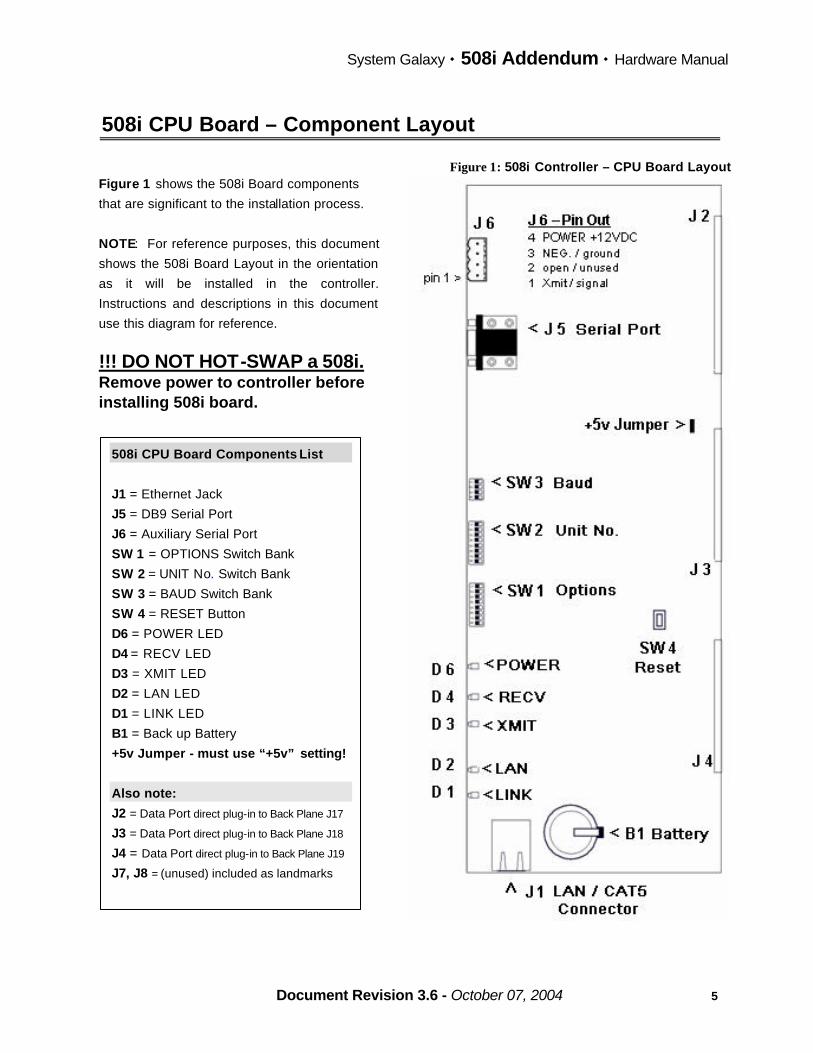
508i CPU Board – Component Layout
Figure 1: 508i Controller – CPU Board Layout
508i CPU Board Components List
J1 = Ethernet Jack
J5 = DB9 Serial Port
J6 = Auxiliary Serial Port
SW 1 = OPTIONS Switch Bank
SW 2 = UNIT No. Switch Bank
SW 3 = BAUD Switch Bank
SW 4 = RESET Button
D6 = POWER LED
D4 = RECV LED
D3 = XMIT LED
D2 = LAN LED
D1 = LINK LED
B1 = Back up Battery
+5v Jumper - must use “+5v” setting!
Also note:
J2 = Data Port direct plug-in to Back Plane J17
J3 = Data Port direct plug-in to Back Plane J18
J4 = Data Port direct plug-in to Back Plane J19
J7, J8 = (unused) included as landmarks
Figure 1 shows the 508i Board components
that are significant to the installation process.
NOTE: For reference purposes, this document
shows the 508i Board Layout in the orientation
as it will be installed in the controller.
Instructions and descriptions in this document
use this diagram for reference.
!!! DO NOT HOT-SWAP a 508i. Remove power to controller before installing 508i board.

System Galaxy 508i Addendum Hardware Manual
6 Document Revision 3.6 - October 07, 2004
Serial Ports (J5, J6)
There are two serial ports on the 508i CPU Board, labeled “J5” and “J6”.
The J5 Port is used for the initial setup/configuration of the IP connections of the CPU Board. Connect the
Host PC serial cable to this port for initial setup using HyperTerminal. Detailed instructions for programming
TCP/IP setup are in Step 13 of this addendum.
The J6 Port is used for serial communication to the Cypress clock. (See Figure 1 - 508i Board Diagram in
this Addendum for view of connector with pin-out.). The pin-out of the connector for Cypress clock
connection is listed below.
J6 Pin Out (see Figure 1 - 508i Board Diagram)
Pin 1 = transmit / signal
Pin 2 = open / unused
Pin 3 = ground / negative
Pin 4 = power / positive (+12VDC ONLY)
HINT: The J6 Port can be use to provide temporary auxiliary power when performing pre-installation
configuration (i.e. pre-configuring the IP Connections before physically installing the board). The pin-out for
J6 is also shown on the board diagram (See 508i Board Diagram - Figure 1 in this Addendum for view of
connector with pin-out). Use pins 3 and 4 to provide power at +12 VDC ONLY.
Ethernet Jack (J1)
At the bottom edge of the 508i CPU board is the Ethernet jack (J1) for establishing a TCP/IP connection
between the 508i Controller and the Host PC. This is a Cat-5 connector and will only support a 10Mb
network connection.
NOTE: The Loop Communication PC can connect to the Primary 508i Controller via Ethernet connection on
the CPU board or through the RS-232 connector on the backplane, but cannot connect through both
simultaneously.

System Galaxy 508i Addendum Hardware Manual
Document Revision 3.6 - October 07, 2004 7
“OPTIONS” Switch Bank Positions (SW 1)
The “OPTIONS” Switch Bank (SW1) is located along the side of the 508i CPU board. This bank of eight
switches enables certain functions for the panel. Below is a description of the functions for each position for
the 508i Controller.
REMEMBER: A controller reads the switch positions upon controller reset ONLY. Remember to take the necessary steps to ensure controller data memory is preserved when a WarmStart is needed. Carefully read CAUTION noted in the section about WARMSTART MODE.
OPTIONS Switch 1 – Reset Modes (ColdStart vs. WarmStart)
• COLDSTART MODE: With the OPTIONS Switch 1 ON (up) and press the RESET button to induce a
COLDSTART. The 508i controller is shipped with Switch 1 in the UP position so that it has a clean start
when it is initially installed and powered-on at the site.
WARNING: A ColdStart erases controller data memory (i.e. programming/configuration is deleted).
FLASH programming is not affected.
NOTE: IF a ColdStart occurs, the controller configuration must be restored by reloading it from
the system database via the Loop Communication PC and System Galaxy software. See
the SG-Hardware Manual for instructions on restoring system configuration to the controller’s
data memory bank.
IMPORTANT: After initial power-up of the controller, Switch 1 should be placed in the down
position to prevent an accidental ColdStart.
• WARMSTART MODE: With the OPTIONS Switch 1 OFF (down) and with a fresh Backup Battery (B1) properly installed, press the RESET button to induce a WARMSTART. A WarmStart should not
delete/erase the controller data memory.
IMPORTANT: A controller reset can occur for any of these reasons:
a) The RESET button is depressed
b) The voltage to the controller drops below 11.5 volts
c) The CPU automatically resets itself based on a built-in watchdog timer
d) A Power surge occurs
NOTE: A controller reset can also be issued by the software from the Host PC. The type of reset (warm
or cold) is can be determined by the software, but is dependant on Options Switch 1 being in the down
position. If a warm reset is issued from the SG software and Options Switch 1 is in the UP position, a
ColdStart is invoked.
CAUTION: In order to preserve memory during a controller reset, the 3Volt Backup Battery (B1) must be
installed and the insulation tab removed and Switch 1 OFF (down). A controller reset will induce a
ColdStart If the battery is low or missing, or the insulation tab is not removed,

System Galaxy 508i Addendum Hardware Manual
8 Document Revision 3.6 - October 07, 2004
OPTIONS Switch 2 – unused
OPTIONS Switch 2 is unused on the 508i model controller. Thus it does not set "EPROM mode" as it did in
the original 500 series controllers.
OPTIONS Switches 3 and 4 - Communication Mode
OPTIONS Switches 3 and 4 are used to set the method of communication between the 508i controller and
the Loop Communication PC. The switch combinations for each communication mode are listed in the
following table.
Table 2: Communication Modes
Switch 3 Switch 4 Method of Communication
down down Direct cable connection
up down Modem connection
down up Ethernet/network connection
up up setting for clock unit (see below)
MODEM: In setting up a modem connection, make sure the controller has a “direct” phone number. It
cannot use an extension or other type of phone connection that is interrupted by a switching system that
would require dialing more numbers or being connected by a receptionist.
Ethernet/Network: A Lantronix MSS-100 device IS NOT used in setting up an Ethernet/Network
connection on a 508i CPU Board. The network must also use a TCP/IP format.
Clock: If you are attaching a Cypress clock to a secondary controller using the com port of that controller,
Switches 3 and 4 of that controller must be UP. If your primary controller is a 508i controller, you can attach
the Cypress Clock to the primary 508i CPU Board via the J6 serial port.
OPTIONS Switches 5 and 6 – Network Bridge using Native IP
If a network bridge is being established between two 508i controllers, the Extending Secondary Controller should
have OPTIONS Switch 4 in the ON position and OPTIONS Switch 5 in the ON position and the Remote Primary
Controller should have OPTIONS Switch 4 in the ON position and OPTIONS Switch 6 in the ON position,
which forces it to be a primary controller. If the controller is not part of a network bridge, Switches 5 and 6
should be left in the OFF position. See the section "Connecting Controllers using a Network Bridge" in the
SG Hardware Manual for more information.
Table 3: Network Bridge Switch Settings for Native IP ONLY (by controller)
Extending Secondary Controller Remote Primary Controller
OPTIONS SWITCH OPTIONS SWITCH
Switch
4
Switch
5
Switch
6
Switch
4
Switch
5
Swi tch
6 ON ON OFF ON OFF ON

System Galaxy 508i Addendum Hardware Manual
Document Revision 3.6 - October 07, 2004 9
OPTIONS Switch 7 and 8 - reserved
OPTIONS Switches 7 and 8 are unused and/or reserved.
“UNIT No.” Switch Bank (SW2)
Next to the OPTIONS Switch is the UNIT No. Switch Bank. The combination of switch positions on this bank
determines the Unit Identification Number of the controller.
REMEMBER: A controller reads the switch positions upon controller reset ONLY. Remember to take the necessary steps to ensure controller data memory is preserved when a WarmStart is needed. Carefully read CAUTION noted in the section about WARMSTART MODE.
The Primary Controller of each Loop is the controller that connects to the Loop Communication PC. This
Primary Controller must always be assigned Unit Number 000. If there are additional controllers in the loop,
each one MUST have a unique ID number. Secondary Controller unit numbers can range from ‘001’ through
‘254’, allowing for systems of up to 255 controllers. There cannot be two controllers on the same loop with
the same Unit Number. Controllers on different loops will duplicate unit numbers.
It is recommended that secondary units be assigned unit numbers in ascending order starting with Unit ‘001’.
The table below lists the different switch settings for Unit Numbers 000-05. The Appendix lists the switch
settings for unit numbers 0 through 99. 0 = Switch Down 1 = Switch Up
Table 4: Unit Number Switch Settings for Controller ID’s
Unit No. - DIP Switch Positions 1 2 3 4 5 6 7 8
00 0 0 0 0 0 0 0 0 01 1 0 0 0 0 0 0 0 02 0 1 0 0 0 0 0 0 03 1 1 0 0 0 0 0 0 04 0 0 1 0 0 0 0 0 U
nit I
D #
05 1 0 1 0 0 0 0 0
You can also use the Calculator tool in Windows to determine the unit number. Choose the Scientific View.
With "Dec" selected and type in a number (for example, "5" for unit number 5). Change the format to "Bin"
(binary). The equivalent binary number will appear starting with the switch on the left, where the number “0”
represents the switch down and the number “1” represents the switch up.

System Galaxy 508i Addendum Hardware Manual
10 Document Revision 3.6 - October 07, 2004
“BAUD” Switch Bank (SW3)
Next to the UNIT No. Switch, is the “BAUD” Switch Bank. The Baud switches are used to set the communication
parameters and must match those selected on the PC or modem. These switches should be set in the
factory default position at “9600 baud” unless a change is recommended by Galaxy Technical Support. Following is a list of the possible switch combinations and their respective baud rate settings.
Table 5: Baud Rate Settings
BAUD Switch Settings
9600 All switches in the ON (up) position. (Factory Default)
4800 Switches 1 and 3 in the ON (up) position, Switches 2 and 4 in the OFF (down) position.
2400 All switches in the OFF (down) position.
REMEMBER: A controller reads the switch positions upon controller reset ONLY. Remember to take the necessary steps to ensure controller data memory is preserved when a WarmStart is needed. Carefully read CAUTION noted in the section about WARMSTART MODE.
“RESET” Switch (SW4)
In the lower half of the 508i CPU Board is a push-button labeled “RESET”. This button is most commonly
used to reset the controller in the event of a lock-up.
The RESET button is also used if a switch setting change is necessary. When the controller is first powered
up, the CPU reads the UNIT No. and OPTIONS switches. If any OPTIONS switches or UNIT No. switches are
changed, a reset must be performed. Simply press the button and release. The new parameters will then
take effect.
ALWAYS MAKE SURE OPTION SWITCH ONE IS IN THE DESIRED POSITION (WARM OR COLD
RESET) BEFORE PRESSING THE RESET BUTTON. (See the section on "OPTIONS Switch 1 - Reset
Mode" in this manual for more information).

System Galaxy 508i Addendum Hardware Manual
Document Revision 3.6 - October 07, 2004 11
LEDs (D1 thru D5)
There are five indication LEDs along the edge of the CPU Board that provide some basic information about
the system (the original 500 series had three). Each is labeled by its function.
Three LEDs are labeled PWR (Power), RECV (Receive), and XMIT (Transmit). During normal operation, all
three should be lit, however the RECV and XMIT LEDs will flicker.
§ D6 PWR (yellow) should be brightly lit, indicating the CPU Broad is receiving +12 VDC. However,
the PWR LED will light with less than +12VDC. Always check DC voltage between J9 pins 8 and 9
to verify that the controller is receiving approximately +13.8 VDC.
§ D4 RECV (red) indicates that data is being received through the loop input path.
§ D3 XMIT (green) indicates that data is being transmitted by the CPU to the loop.
The LAN and LINK LEDs are new with the 508i CPU Board. These LEDs will respond to any detected
Ethernet traffic. They are only valid when a TCP/IP Ethernet connection is being used between the
controller and the Loop Communication PC.
§ D2 LAN (yellow) will blink as data is detected on the Ethernet connection.
§ D1 LINK (green) will be lit when a valid Ethernet connection is detected.
Backup Battery (B1)
The CPU Board data memory and clock components depend on battery backup protection in the event of
power loss. In the 508i CPU, there is one battery to support both these functions.
The battery is a standard CR2354, 3V lithium battery. Galaxy recommends changing this battery
semiannually as routine maintenance. Note that battery is shipped in place with a strip of paper (battery
insulation tab) blocking the connection.
IMPORTANT: The strip of paper insulation tab must be removed in order for the battery to function and
provide temporary backup power to the memory chips and clock.
+5 Volt Jumper
The +5 Volt Jumper is used to select the power that is sent to the DPI Boards.
This jumper setting SHOULD NOT BE CHANGED (i.e. jumper should remain in the +5 Volt position).
Unused Connectors (J7, J8)
The J7 and J8 connectors are for development use only.

System Galaxy 508i Addendum Hardware Manual
12 Document Revision 3.6 - October 07, 2004
508i Controller - Installation
Main Installation Checklist
Table 6: 508i Installation Checklist Installation Steps Refer to 1. Mount chassis. (same as 508/502)
2. Wire to other controllers (J9) on the Backplane. (same as 508/502) 3. Wire power supply (J9) on the Backplane. This allows the battery to begin charging. (same as 508/502) 4. Set Option Switches 3 and 4 for the correct Connection type. (same as 508/502) 5. Set Option Switches 5 and 6 if controller is part of network bridge. (same as 508/502) 6. Set Unit Number Switches. (same as 508/502) 7. Install all necessary Dual Port Interfaces. (same as 508/502) 8. Install the Terminal/Network Interface. (same as 508/502) 9. Connect the personal computer to the Primary Controller. pg. 13
10. Connect AC Power (same as 508/502) 11. Push the Reset Button (Option Switch 1 in the up position). (same as 508/502) 12. Put Option Switch 1 in the down position. (same as 508/502) 13. Program IP address (Ethernet connection only) pg. 14
14. Load Flash to Controller(s) (CONDITIONALLY Required) pg. 16
REMEMBER to remove the paper insulation tab from the Battery (B1) n/a WARNING: DO NOT HOT-SWAP a 508i. Remove power to controller before installing 508i board. Hot-swapping this board causes damage to board components. IMPORTANT: notice that the act of loading flash is now conditionally required. See section in this addendum about Verifying and Loading Flash to ensure proper steps are executed.

System Galaxy 508i Addendum Hardware Manual
Document Revision 3.6 - October 07, 2004 13
Steps 1 - 8
Steps 1 - 8 have not changed from the original 500 series controllers (508 and 502 model). Refer to the SG
Hardware Manual for instructions pertaining to Installation Steps 1 through 8.
Step 9 - PC to Controller Connections
Direct Connection, Dial-Up Connection
The Installation instructions for Direct Connections and Dial-Up Connections have not changed from the
original 500 series controllers (508 and 502 model). Refer to the SG Hardware Manual for instructions
pertaining to Installation Step 9.
TCP/IP Connection
With the 508i controller, the Lantronix Micro-Serial Server (MSS) is NOT used for TCP/IP
connections between the PC and Primary Controller.
Technician must complete the setup of the IP address and other network settings (described in Step-13 Program IP Address ) before connecting the Ethernet cable to the Cat-5 (J1) connector on the CPU Board.
IMPORTANT: Loading FLASH is conditionally required for 508i Board installation. See Step 14 for
instructions for verifying and loading the Flash.
NOTE: The Ethernet connection MUST be a 10Mb connection, NOT a 100Mb connection. The Network
Hub/Switch must support 10Mb Full Duplex.
Steps 10 - 12
Steps 10 - 12 have not changed from the original 500 series controllers (508 and 502 model). Refer to the
SG Hardware Manual for instructions pertaining to Installation Steps 10 – 12.
WARNING: DO NOT HOT-SWAP a 508i. Remove power to controller before installing 508i board. Hot-swapping this board causes damage to board components.

System Galaxy 508i Addendum Hardware Manual
14 Document Revision 3.6 - October 07, 2004
Step 13 - Program IP Address
Programming the IP Address of the controller is only necessary for TCP/IP connections (i.e. when using
Native IP). A serial cable with correct parameters is shipped with the 508i controller. The following
information describes the 508i serial cable. The connections must be: Pin 2 to Pin 2, Pin 3 to Pin 3, Pin 5
to Pin 5. The cable must have a DB9 female connector on one end and a DB9 male connector on the
other. Connect the cable to the J5 serial port (the debugging port) of the CPU Board and the standard 9-pin
serial port on the PC or laptop that will run HyperTerminal.
A. Start a HyperTerminal connection from the Host PC with the following settings:
Bits per Second = 57,600K
Parity = None
Data Bits = 8
Stop Bits = 1
Flow Control = None
B. Once the connection is established, you MUST type the following entries in lowercase.
1) Press the <Enter> key.
2) At the “login” prompt, type “install” and press the <Enter> key.
3) At the “>” prompt, type “config” and press the <Enter> key.
• A list of current settings is returned (including the controller model/version)
ending with the prompt “Do you wish to make changes? (yes/no)”.
4) To change the settings, type "yes" and pre ss <Enter> key.
• This will allow the settings to be edited and pressing the <Enter> key advances
you to the next available setting.
• If you don’t want to change the current setting, simply press <Enter> key to skip
to the next setting.
5) The Password field: the HyperTerminal session will either display the existing password or
the prompt “Password (not specified)” when password is unset. You should use the existing
password if it is setup. You should make a password if one is not specified.
• CAUTION! The Password field can be bypassed (<space bar>, <Enter> key)
HOWEVER this deletes the existing password. If you skip the password field you,
you will NOT be able to connect by Telnet (off-site access) and will be limited to
on-site serial (HyperTerminal) connection for future updates.
• IMPORTANT: See the “Connection Settings” Table for important information.
6) Once you have completed the necessary settings, type "yes" (lowercase) to save the
changes.
NOTE: The connection settings are described in the following table.

System Galaxy 508i Addendum Hardware Manual
Document Revision 3.6 - October 07, 2004 15
Table 7: Connection Settings
Setting Description
Serial # The serial number of the CPU board (also labeled on the board)
MAC Address The MAC address assigned to the CPU board by Galaxy Control Systems.
Package # The package number represents the type of controller (2 = 508i).
IP Address The IP Address assigned to the controller must be static, in the standard "dotted"
format (nnn.nnn.nnn.nnn). The IP address must be assigned by the network
administrator. The default IP address assigned to every board by Galaxy Control
Systems is 63.122.126.203.
Network Mask The Network Subnet Mask must be assigned by the network administrator.
Gateway Address The Gateway address must be assigned by the network administrator.
Partner IP Address In the case of a Network Bridge, the Extending Secondary controller MUST have a
Partner IP Address and it MUST match the IP Address of the Remote Primary
controller.
• When a Partner IP Address is specified, the controller will only accept an
incoming connection from the designated address.
• A Partner IP Address is not needed for the Primary and Remote Primary
controllers.
Partner Port Partner Port is an optional setting. For Primary and Remote Primary controllers, this
setting specifies the port used for listening for connections. For Secondary
controllers, this setting specifies the destination port and the local outbound port. If
left unset, the controller defaults to port 3001.
Password If set, the password replaces the controller serial number in the security algorithm
that controls the connection between the controller and a PC.
If set for a Primary Controller, the password must also be typed into the Password field in the System Galaxy software. Galaxy recommends that the same
password be used for all 508i controllers in each installation.
• A Password is optional for a Primary controller.
• A Password is required for the Extending Secondary and Remote Primary
controllers AND the passwords must match when using a Network Bridge.
IMPORTANT: A password should be set/used. Bypassing the password field
will erase the password and you will be limited to on-site connection for future
updates (i.e. unable to utilize telnet to connect remotely).
See Step13, part B, item 5 for information.

System Galaxy 508i Addendum Hardware Manual
16 Document Revision 3.6 - October 07, 2004
Step 14 - Verify and Load Flash
Loading FLASH is conditionally required. This section describes the steps to verify the Flash version and determine the necessary condition for loading, as well as Load Flash when needed.
NOTE: The 508i CPU board arrives with a pre-loaded version of Flash code. For proper operation and compatibility, the version of Flash on the 508i Board MUST match the Flash version on System Galaxy’s “s28 Flash file”.
IMPORTANT: If the Loop Communication PC’s flash is different than the 508i Board’s flash, then it is necessary to load the Flash code from the PC’s “.s28 file” to the 508i CPU Board. If the Loop Communication PC and the 508i versions of flash are the same, then loading flash is not necessary. (The name “s28” refers to the file name extension on the System Galaxy Flash code file.)
WARNING: If ANY 508i Board in the system is running a different version of flash it must be loaded. ALL 508i Board’s MUST be running the same version of flash as the System Galaxy s28 Flash file. WARNING: DO NOT HOT-SWAP a 508i. Remove power to controller before installing
508i board. Hot-swapping this board causes damage to board components.
Starting System Galaxy and Connecting Loop(s)
System Galaxy software must be running and connected to the Loop(s) containing the 508i controller(s). If the Loop status is not connected then Flash cannot be verified/loaded.
NOTE: To load Flash, System Galaxy Version 6.01 or higher Maintenance Release must be running. Use the following steps to Verify Flash (part 1) and determine the necessity to Load. Executing the steps for Loading Flash (part 2) is conditionally required.
GCS Loader Screen
Verifying and/or Loading Flash is done through the GCS_Loader screen. Opening the Loader screen is done by one of two options.
NOTE: There is a new screen tab labeled “EZ80 Flash” in the Loader screen. EZ80 Flash code is NOT listed in banks. User must select the EZ80 Flash tab to verify and load flash.
1) Opening Loader screen from the Start Menu: Ø Select Windows’ Start>Program Files>System Galaxy>GCS_Loader
§ the user/technician can choose to verify “all loops” or individual loops
§ user/tech can load as necessary without opening additional Load screens § the Loader screen can be closed without shutting down restarting System Galaxy
software when the procedure is complete
2) Opening Loader screen from the hardware tree: Ø Right -click the Loop icon in the System Galaxy hardware tree and select ‘Load’
§ the user/technician will be limited to verifying and loading loops individually
§ the screen(s) will remain open until the System Galaxy software is restarted The following figure shows the Loader screen with the EZ80 Flash tab.

System Galaxy 508i Addendum Hardware Manual
Document Revision 3.6 - October 07, 2004 17
GCS Loader Screen :
Figure 2: GCS_Loader Screen with EZ80 Flash tab
Once the Loader screen is open, user will navigate to the EX80 Flash tab and follow the instructions for verifying flash.
Part 1: Verifying Flash version:
1. With Loop(s) connected, open the Loader Screen from the Loop Communication PC’s Start Menu
by selecting Start>Programs>System Galaxy>GCS_Loader (Loader screen opens/displays).
2. You can select "All controllers" to load, but the ACK controller must be set to a 508i controller.
3. Pick the ‘EZ80 Flash’ tab on the Loader screen and click the Browse button (‘Open’ window displays)
4. Select the "508i.s28" file and click the Open button (the “s28 file” Flash version is displayed in the
top text field).
5. Click the Connect button (Z-link status will display “connected” on the Load screen).
~ proceed to next step.

System Galaxy 508i Addendum Hardware Manual
18 Document Revision 3.6 - October 07, 2004
~ continued from previous step
6. Click the Get Controller Info button (the controller flash version displays for each 508i controller).
Note: if you have a version of System Galaxy that is prior to 6.04 you may need to toggle to the 500
Flash tab and back to the ‘EZ80 Flash’ tab to recover the lower Controller Info text field display back on
the ‘EZ80 Flash’ tab.
7. Once the controller information is displayed, confirm the Flash version for every 508i in the list
(displayed in the lower text field) matches the s28 Flash version (displayed in the upper text field).
• Condition A = No Load Needed: If all 508i controllers are matching the s28 Flash version,
then no load is necessary.
IMPORTANT: Confirmation of controller information must be completed for all 508i
controllers in all Loops.
• Condition B = Flash Load Needed: If any 508i returns a different version than the s28
Flash version, then only that (non-compatible) controller must be loaded - see Part 2 for
Loading Flash. If a mix of compliant and non-compliant controllers is returned then it is
recommended Part 2 – Loading Flash must be done for non-compliant controllers
separately.
IMPORTANT: Loading Flash induces a ColdStart to the controller. All cold started
controllers will lose existing data/setup. It is NOT recommended that you reset
controllers that are already running a compatible version of Flash.
Part 2: Load Flash:
8. In the Loader screen/ ‘EZ80 Flash’ tab, click the Begin Flash Load button to load flash to the
controller(s). This may take 5 -15 minutes. REMEMBER that loading Flash induces a ColdStart to
the selected controller(s).
9. When Load is complete, click the Check Flash button.
10. Select the option to "Validate and Burn Permanently into Flash", and click OK.
11. Zlink status will temporarily disconnect, then reconnect automatically and a message “controller
came up in flash mode successfully” should be returned to the Controller Info field (lower text box).
12. If the Controller Info field does not return a message that a ColdStart occurred, then a
ColdStart to the newly loaded controller(s) should be done.
Repeat the steps above as needed to complete the verification and conditional loading of Flash to
remaining loops and controllers.
Note: The ability to Load Flash using HyperTerminal is possible when correcting situations where a
controller is not communicating with the System Galaxy software through conventional means. For help
with this process call Galaxy Technical Support (800) 445-5560.

System Galaxy 508i Addendum Hardware Manual
Document Revision 3.6 - October 07, 2004 19
Network Bridges using TCP/IP The 508i controller can be used to establish a TCP/IP connection for a network bridge to another loop without the use of a Lantronix MSS-100.
Network Bridge with Native IP: If a Network Bridge is to be configured using the 508i native IP, then both ends (i.e. Extending Secondary and Remote Primary) of the bridge must be 508i controllers using the native IP. You cannot use a 508i controller on one end of the bridge and a 500-series controller using a Lantronix device on the other end. Network Bridge with RS232: If using an RS -232 connection, the Extending Secondary and Remote Primary controllers can be 508i or the original 500 series controllers.
List of Commands When connected to the CPU either through HyperTerminal session (or via Telnet session once the IP address is correctly installed and configured), several commands are available for programming and diagnostic functions. This list of commands is also available by typing "help" at the command prompt.
To initiate a Telnet session go to the Host PC’s Start Menu, select Run and type “telnet” and the IP address of the desired 508i controller.
Example: “telnet 63.122.126.203” (this number is an example only; you will need to know the valid IP Address of the desired controller).
At the login prompt type “install” and provide the password you set originally in step 13 (if a password was not configured on initial setup then you will not be able to access the controller via telnet). NOTE: In a Telnet connection, after signing in, type the "crlf" command to format the screen to be readable display. Type "echo" if you wish to see the commands you are typing.
NOTE: A HyperTerminal / Telnet session can be used to change settings on any controller that is connected to Ethernet. This would typically be the Primary controller and in the case of a 508i Network Bridge, the Extended Secondary and Remote Primary Controllers.
net This command returns the statistics of the Ethernet port.
port n (where n equals a port number) This command returns troubleshooting information for the specified port
switches This command returns the current settings (in Binary) of all three banks of dip switches (Unit Number, Options, and Baud), and the meaning of those settings.
version This command returns the flash version for the primary controller.
config This command allows you to set up the IP address and subnet mask for this controller, as well as other settings. It also gives a list of the current settings. To modify these settings, type "yes" (lowercase).
NOTE: see the section Step-13 Programming the IP Address for information on changing the IP Programming and viewing the Connection Setting table.