Embed Size (px)
Citation preview

7/30/2019 501624main Ta08 Sioss Draft Nov2010 A
http://slidepdf.com/reader/full/501624main-ta08-sioss-draft-nov2010-a 1/36
DRAFT
National Aeronautics and Space Administration
Nvmb • 2010
DRAFT Science inSTRumenTS, ObSeRvATORieS,AnD SenSOR SySTemS ROADmAp
Technology Area 08
Richard D. Barney, Chair Jill J. BaumanLee D. Feinberg Daniel J. Mccleese
Upendra N. SinghH. Philip Stahl

7/30/2019 501624main Ta08 Sioss Draft Nov2010 A
http://slidepdf.com/reader/full/501624main-ta08-sioss-draft-nov2010-a 2/36
DRAFT
is page is intentionally left blank

7/30/2019 501624main Ta08 Sioss Draft Nov2010 A
http://slidepdf.com/reader/full/501624main-ta08-sioss-draft-nov2010-a 3/36
DRAFT
Tb f Ctts
ForewordExecutie Suary TA08-11. General Oeriew TA08-21.1. T App TA08-21.2. Bfs TA08-51.3. Appb/Tb NASA S Gs, AMPM, DRMs, DRAs TA08-51.4. Tp T Cs TA08-5
2. Detailed Portolio Dicuion TA08-62.1. Smm Dsp TA08-62.2. T Ns TA08-6
2.2.1. Science Mission Directorate Technolog y Needs TA08-7 2.2.1.1. AstrophysicsTechnologyNeeds TA08-7 2.2.1.2. EarthScienceTechnologyNeeds TA08-7 2.2.1.3. HeliophysicsTechnologyNeeds TA08-9 2.2.1.4. PlanetaryScienceTechnologyNeeds TA08-122.2.2. SIOSS Technology Area Roadmaps TA08-12 2.2.2.1. RemoteSensingInstruments/SensorsRoadmap TA08-12
2.2.2.2. ObservatoryTechnologyChallenges TA08-20 2.2.2.3. In-SituInstruments/SensorsTechnologyChallenges TA08-213. Interdeendency with Other Technology Area TA08-264. Poile Beneit to Other National Need TA08-28 Acrony TA08-29 Acknowledgeent TA08-30

7/30/2019 501624main Ta08 Sioss Draft Nov2010 A
http://slidepdf.com/reader/full/501624main-ta08-sioss-draft-nov2010-a 4/36
DRAFT
ForewordNASA’s integrated technology roadmap, including both technology pull and technology push strategies,considers a wide range o pathways to advance the nation’s current capabilities. Te present state o this efortis documented in NASA’s DRAF Space echnology Roadmap, an integrated set o ourteen technology area roadmaps, recommending the overall technology investment strategy and prioritization o NASA’s spacetechnology activities. Tis document presents the DRAF echnology Area 08 input: Science Instruments,Observatories, and Sensor Systems. NASA developed this DRAF Space echnology Roadmap or use by the National Research Council (NRC) as an initial point o departure. Trough an open process o community engagement, the NRC will gather input, integrate it within the Space echnology Roadmap and provide NASA with recommendations on potential uture technology investments. Because it is dicult to predict the widerange o uture advances possible in these areas, NASA plans updates to its integrated technology roadmap on
a regular basis.

7/30/2019 501624main Ta08 Sioss Draft Nov2010 A
http://slidepdf.com/reader/full/501624main-ta08-sioss-draft-nov2010-a 5/36
TA08-1DRAFT
across all divisions require new or improved detec-tor technology. Tese broad categories were thenorganized into a echnology Area BreakdownStructure (ABS) (Figure 1). A three-tier ABSstructure was used to organize diverse technologiescovering Remote Sensing Instruments/Sensors,
Observatories, and In-situ Instruments/Sensors.Remote Sensing Instruments/Sensors includescomponents, sensors, and instruments sensitive toelectromagnetic radiation including photons, as well as any other particles, electromagnetic elds,both DC and AC, acoustic energy, seismic energy,or whatever physical phenomenology the sciencerequires. Observatory includes technologies thatcollect, concentrate, and/or transmit photons. In-situ Instruments/Sensors includes components,sensors, and instruments sensitive to elds, waves,particles that are able to perorm in-situ character-ization o planetary samples.
Te nal roadmapping step ocused on identi-ying technologies that may not be directly linkedto SMD missions that show the potential or rad-ical improvement in measurement capabilities. A push technology questionnaire was developed by the SIOSS eam and sent to Chie echnologistsat all NASA centers as well as to several memberso the NASA scientic community. As a result o this eedback, we considered many new technolo-gies and measurement techniques.
Te ollowing tables/roadmaps are included inthe SIOSS report:
exeCuTive SummaryTe Science Instruments, Observatories, and
Sensor Systems (SIOSS) echnology Area Road-map leverages roadmapping activities rom the2005 NASA Advanced Planning and Integra-tion Oce (APIO) roadmap assessments: Ad-
vanced Telescopes and Observatories and Science Instruments and Sensors . Te SIOSS technology needs and challenges identied in this documentare traceable to either specic NASA science mis-sions planned by the Science Mission Director-ate (‘pull technology’) or emerging measurementtechniques necessary to enable new scientic dis-covery (‘push technology’).
Te SIOSS eam employed a multi-step pro-cess to generate the roadmaps. Te rst step wasto review existing governing documents (such asDecadal Surveys, roadmaps, and science plans) oreach o the our NASA Science Mission Divisions
(SMD): Astrophysics, Earth Science, Heliophys-ics, and Planetary. From these documents, spe-cic technology needs were identied that enableplanned and potential uture missions. Detailedlists o these technology needs or each SMD di-vision were tabulated and then reviewed and re-ned by individual mission and technology-devel-opment stakeholders.
Te second step involved consolidating thetechnology needs or each mission into broad cat-egories or analysis. For example, many missions
Figure 1. Technology Area Breakdown Structure

7/30/2019 501624main Ta08 Sioss Draft Nov2010 A
http://slidepdf.com/reader/full/501624main-ta08-sioss-draft-nov2010-a 6/36
TA08-2 DRAFT
• SIOSS echnology Area Strategic Roadmap• op echnologies able• echnology Area Breakdown Structure• Astrophysics, Earth Science, Heliophysics, and
Planetary echnology Needs ables• Remote Sensing Instruments/Sensors
echnologies Challenges able and Roadmap• Observatory echnologies Challenges able
and Roadmap• In-situ Instruments/Sensors echnology
Challenges able and Roadmap• Push echnologies and Measurement
echniques Summary ables• Interdependencies between SIOSS echnology
and other echnology Assessment AreasTe roadmaps or Remote Sensing Instruments/
Sensors (8.1), Observatory (8.2), and In-Situ In-struments/Sensors (8.3) were merged into an over-all echnology Area Strategic Roadmap (ASR)required by the Oce o the Chie echnologistand shown in Figure 2. Tis summary roadmapincludes multiple technologies linked to similarmissions and includes reerences to key peror-mance targets or both push and pull technolo-gies. It is not meant to establish investment pri-orities.
Te Science Instruments, Observatories, andSensor systems’ top technical challenges tablesummarizes generic classes o near-, mid- andlong-term investments in SIOSS technologies that
would enhance or enable a wide range o poten-tial science missions. Investments in the matura-tion o SIOSS technologies needs to be balancedbetween the shorter- and longer-term needs, asmany o the 2017-2022 and beyond technologiescan take longer to develop. For each area, the chal-lenge is to advance the state o the art in the ech-nology Categories shown below by at least 2X to10X and, in the case o long-term needs, to de-velop entirely new revolutionary capabilities. Teop echnical Categories are not in any priority order; rather the list is organized by general need within selected timerames.
Top Technology CategoriesPresent to 2016• In-situ Sensors or Planetary Sample Return/
Analysis• Advanced Microwave Components and
Systems• High Eciency Coolers• Large Focal Plane Arrays
• High Eciency Lasers• Low-Cost, Large-Aperture Precision Mirrors• In-situ Particle, Field and Wave Sensors• Radiation-Hardened Instrument Components
2017-2022
• High-Contrast Exoplanet echnologies• Ultra-Stable Large Aperture UV/O elescopes• Quantum Optical Intererometry (Atomic
Intererometers)• Spectrometers or Mineralogy • Sample Handling • Extreme Environment echnologies
2023 and Beyond • Surace Chronology • Particle and Field Detectors• Advanced spatial intererometric imaging
While the SIOSS roadmap concentrates primar-ily on SMD applications (astrophysics, Earth, he-liophysics and planetary science), SIOSS technol-ogy is broadly applicable to the entirety o NASA missions. Section 3 and able 9 details how SIOSStechnology can enable and enhance applicationsrelated to many other NASA mission directorates.
1. General overview
1.1. Tchc appchTe Science Instruments, Observatories, and
Sensor Systems (SIOSS) echnology Area Road-map leverages roadmapping activities rom the2005 NASA Advanced Planning and Integra-tion Oce (APIO) roadmap assessments: Ad-vanced elescopes and Observatories and ScienceInstruments and Sensors. Te SIOSS technology needs and challenges identied in this documentare traceable to either specic NASA science mis-sions planned by the Science Mission Director-ate (‘pull technology’) or emerging measurementtechniques necessary to enable new scientic dis-covery (‘push technology’).
Te SIOSS eam employed a multi-step pro-
cess to generate the roadmaps. Te rst step wasto review existing governing documents (suchas Decadal Surveys, roadmaps, and the scienceplans) or each o the our NASA Science MissionDivisions (SMD): Astrophysics, Earth Science,Heliophysics, and Planetary. From these docu-ments, specic technology needs were identiedthat enable planned and potential uture missions.Detailed lists o these technology needs or eachSMD division were tabulated and then reviewed

7/30/2019 501624main Ta08 Sioss Draft Nov2010 A
http://slidepdf.com/reader/full/501624main-ta08-sioss-draft-nov2010-a 7/36
TA08–3/
Figure 2: SIOSS #8 Technology Area Strategic Roadmap
DRAFT

7/30/2019 501624main Ta08 Sioss Draft Nov2010 A
http://slidepdf.com/reader/full/501624main-ta08-sioss-draft-nov2010-a 8/36
Tis page is intentionally left blank
7/30/2019 501624main Ta08 Sioss Draft Nov2010 A
http://slidepdf.com/reader/full/501624main-ta08-sioss-draft-nov2010-a 9/36
TA08-5DRAFT
and rened by individual mission and technolo-gy-development stakeholders. Te second stepinvolved consolidating the technology needs oreach mission into broad categories or analysis.Tese broad categories were then organized intoa echnology Area Breakdown Structure (ABS).
A three-tier ABS structure was used to organizediverse technologies covering Remote Sensing In-struments/Sensors, Observatories, and In-situ In-struments/Sensors.
Remote Sensing Instruments/Sensors includescomponents, sensors, and instruments sensitive toelectromagnetic radiation including photons, as well as any other particles (charged, neutral, dust),electromagnetic elds, both DC and AC, acous-tic energy, seismic energy, or whatever physicalphenomenology the science requires. Observato-ry includes technologies that collect, concentrate,and/or transmit photons. In-situ Instruments/
Sensors includes components, sensors, and in-struments sensitive to elds, waves, and particlesand able to perorm in-situ characterization o planetary samples.
Te nal roadmapping step ocused on identi-ying “push” technologies that show promise o radically improving measurement capabilities thatenable emerging missions. A push technology questionnaire was developed by the SIOSS eamand sent to Chie echnologists at all NASA cen-ters as well as to several members o the NASA scientic community. As a result o this eedback, we considered many new technologies and mea-
surement techniques not directly linked to NASA missions.
1.2. BtsNASA’s pursuit o science and exploration can-
not proceed without the development o new re-mote- sensing instruments/sensors, observatories,and sensor technologies. Tese technologies arenecessary to collect and process scientic data, ei-ther to answer compelling science questions as oldas humankind (e.g., how does lie begin?) or toprovide crucial knowledge to enable robotic mis-sions (e.g., remote surveys o Martian geology to
identiy optimal landing sites). Several o thesetechnologies are also required to support humanmissions. In particular, they are needed to deter-mine the saety o the environment and its suit-ability or human operations. Section 3.0 detailslinkages with other As.
1.3. appcbt/Tcbt t naSaSttgc Gs, amPm, drms, dras
Te SIOSS technology needs and challenges
identied in this document are directly traceableto either specic NASA science missions plannedby the Science Mission Directorate (‘pull technol-ogy’) or emerging measurement techniques nec-essary to enable new scientic discovery (‘pushtechnology’).
Te set o top-level strategic documents listedbelow were used to prepare the SIOSS roadmaps.Tese sources included a variety o planning doc-uments that articulate NASA and research com-munity priority objectives. Additionally, a com-prehensive design reerence mission set wascompiled rom the specic reerence documents, with emphasis on the 2010 NASA Science Planand Agency Mission Planning Maniest (4/2010).
Specic reerence documents include:• Advanced Telescopes and Observatories , APIO,
2005• Science Instruments and Sensors Capability ,
APIO, 2005• New Worlds, New Horizons in Astronomy and
Astrophysics , NRC Decadal Survey, 2010• Panel Reports — New Worlds, New Horizons
in Astronomy and Astrophysics , NRC DecadalSurvey, 2010
• Heliophysics, e Solar and Space Physics o a New ERA, Heliophysics Roadmap Team Report to the NASA Advisory Council , 2009
• Earth Science and Applications rom Space ,NRC Decadal Survey, 2007
• New Frontiers in the Solar Systems , NRCPlanetary Decadal Survey, 2003
• e Sun to the Earth — and Beyond , NRCHeliophysics Decadal Survey, 2003
• 2010 Science Plan, NASA Science MissionDirectorate, 2010
• Technology Development Project Plan or the Advanced Technology Large Aperture Space Telescope (ATLAST), NASA AstrophysicsMission Concept Study, 2009
• Agency Mission Planning Maniest , 2010• Launching Science: Science Opportunities
provided by NASA’s Constellation System, reporto National Research Council’s Space StudiesBoard, National Academy Press, 2008.
1.4. Tp Tchc Chgsable 1 summaries the top technical challenges
identied or SIOSS. Near- and mid-term chal-lenges represent required improvements in thestate o the art o at least 2X and, in many cases,an order o magnitude (10X) improvement goal.

7/30/2019 501624main Ta08 Sioss Draft Nov2010 A
http://slidepdf.com/reader/full/501624main-ta08-sioss-draft-nov2010-a 10/36
TA08-6 DRAFT
Te long-term challenges are new revolutionary capabilities that would enable entirely new mis-sions. Given the wide array o SIOSS science in-struments, sensors, and observatories, it is di-cult to limit the discussion to just 10 top technicalchallenges. Nearly every scientic application has
unique requirements. Tereore, the challengesoutlined in able 1 represent broad areas. More-over, there is no way to prioritize these top tech-nical challenges other than to group them intogeneral-need timerames. Tereore, this is not a priority ordering.
Finally, it is not the unction o this assessmentto recommend investments in any specic tech-nology. A healthy technology R&D program re-quires three elements: competition, unding, andpeer review. Competition is the astest, most eco-nomical way to advance the state o the art andpeer review is necessary to determine which tech-
nologies should be unded.
2. deTailed PorTFolio diSCuSSion
2.1. S dscpt A three-tier ABS structure (see Figure 1) was
used to organize diverse technologies, including Remote Sensing Instruments/Sensors, Observato-ries, and In-situ Instruments/Sensors.
Remote Sensing Instruments/Sensors includescomponents, sensors, and instruments sensitive toelectromagnetic radiation including photons, as well as any other particles, electromagnetic elds,
both DC and AC, acoustic energy, seismic energy,or whatever physical phenomenology the sciencerequires. Observatory includes technologies thatcollect, concentrate, and/or transmit photons. In-situ Instruments/Sensors includes components,sensors, and instruments sensitive to elds, waves,particles that are able to perorm in-situ character-ization o planetary samples.
2.2. Tchg ns As summarized by SMD’s 2010 Science Plan,
strategic science missions are selected, oten by competitive process, to answer “proound ques-
tions that touch us all.” Tey are dened by NRCDecadal Surveys and are consistent with U.S. na-tional space policy. SMD organizes its scienceportolio along our themes: Astrophysics, EarthScience, Heliophysics, and Planetary Science. Giv-en the availability o guidance documents (such asdecadal reports), SIOSS created comprehensivelists o technology needed to enable or enhanceplanned and potential uture missions. Tese lists were reviewed and rened by individual mission
Pst t 2016 (n T)
i-st Sss f Pt Sp rts i-St ass
Integrated/miniaturized sensor suites to reduce volume, mass & power;Sub-surface sample gathering to >1 m, intact cores of 10 cm, selectivesub-sampling all while preserving potential biological and chemicalsample integrity; Unconsolidate material handling in microgravity; Tem-perature control of frozen samples.
l-Cst, lg-apt Pcs msUV and optical lightweight mirrors, 5 to 10 nm rms, <$2M/m2, <30kg/m2
X-ray: <5 arc second resolution, < $0.1M/m2 (surface normal space),<3 kg/m2
Hgh-ecc lssHigh power, multi-beam/multi-wavelength, pulsed and continuous wave0.3-2.0 µm lasers; High eciency, higher rep rate, longer life lasers.
ac mc Cpts SstsLow-noise ampliers > 600 GHz, reliable low-power high-speed digital &mixed-signal processing electronics; RFI mitigation for >40 GHz; low-costscalable radiometer; large (D/lambda>8000) deployable antennas; lower-mass receiver, intermediate frequency signal processors, and high-spec-tral resolution microwave spectrometers.
Hgh-ecc CsContinuous sub-Kelvin (100% duty cycle) with low vibration, low power(<60W), low cost, low mass, long life
i-st Ptc, F w SssIntegrated/Miniaturized sensor suites to reduce volume, mass and power;Improved measurement sensitivity, dynamic range and noise reduction;Radiation hardening; Gravity wave sensor: 5µcy/√Hz, 1-100mHz
lg Fc-P asFor all wavelengths (X-Ray, FUV, UV, Visible, NIR, IR, Far-IR), required focalplanes with higher QE, lower noise, higher resolution, better uniformity,low power and cost, and 2X to 4X the current pixel counts.
rt-H istt CptsElectronics, detectors, miniaturized instruments; low-noise low-powerreadout integrated circuits (ROIC); radiation-hardened and miniaturizedhigh-voltage power supplies
2017 t 2022 (m T)
Hgh-Ctst ept Tchgs
High-contrast nulling and coronagraphy (1x10⁻¹⁰
, broadband); occulters(30 to 100 meters, < 0.1 mm rms)
ut-Stb lg apt uv/o Tscps> 50 m2 aperture, < 10 nm rms surface, < 1 mas pointing, < 15 nm rmsstability, < $2M/m2
atc itftsOrder-of-magnitude improvement in gravity-sensing sensitivity andbandwidthsScience and navigation applications
2023 B (lg T)
Sp Hg e t et TchgsRobust, environmentally tolerant robotics, electronics, optics for gather-ing and processing samples in vacuum, microgravity, radioactive, high orlow temperature, high pressure, caustic or corrosive, etc. environments.
Spctts f mgIntegrated/miniaturized planetary spectrometers to reduce volume, massand power.
ac Spt itftc iggWide eld imaging & nulling to spectroscopically image an Earth-twinwith >32x32 pixels at 20 parsecs.
m Spccft FtAlignment & positioning of 20 to 50 spacecraft distributed over 10s (to1000s) of kilometers to nanometer precision with milli-arc second point-ing knowledge and stability
Ptc F dtctsOrder-of-magnitude increase in sensitivity
Table 1. Summary o SIOSS Top Near-, Mid- and Far-Term Technology Challenges (2X to 10X Improvements in the State o the Art & New Revolutionary Capabilities)

7/30/2019 501624main Ta08 Sioss Draft Nov2010 A
http://slidepdf.com/reader/full/501624main-ta08-sioss-draft-nov2010-a 11/36
TA08-7DRAFT
and technology-development stakeholders andthen deconstructed and consolidated according tothe ABS o Section 2.1. Tey then were analyzedand grouped into technology-development chal-lenges or push as well as pull technologies. EachABS second-level technology section contains a
separate “push” technology table that was com-piled rom NASA center inputs.
2.2.1. ScienceMissionDirectorateTechnologyNeeds
2.2.1.1. Astrophysics Technology NeedsTe National Academy 2010 Decadal Report,
New Worlds, New Horizons , has recommended a suite o missions and technology-developmentprograms to study three compelling Astrophys-ics science themes: Cosmic Dawn: Searching orthe First Stars, Galaxies and Black Holes; New Worlds: Seeking Nearby, Habitable Planets; Phys-
ics o the Universe: Understanding Scientic Prin-ciples. Te specic missions, with their potentiallaunch dates (which drive RL6 need dates) anddevelopment programs, are:• Wide Field Inrared Survey elescope
(WFIRS), 2018• Explorer Program, 2019/2023• Laser Intererometer Space Antenna (LISA),
2024• International X-ray Observatory (IXO), mid/
late 2020s• New Worlds echnology Development
Program, mid/late 2020s• Epoch o Ination echnology Development
Program, mid/late 2020s• U.S. Contribution to the JAXA-ESA SPICA
Mission, 2017• UV-Optical Space Capability echnology
Development Program, mid/late 2020s• RL 3-to-5 Intermediate echnology
Development Program All can be enhanced or enabled by technology
development to reduce cost, schedule, and peror-mance risks. Te Decadal Survey made several rec-
ommendations, including technology unding or:1) Future missions at a level o ~10% o NASA’santicipated budget or each mission to reduce risk and cost; 2) New Worlds, Infation Probe and Fu-ture UV-Optical Space Capability Denition ech-nology Programs to prepare or missions beyond2020; and 3) “General” technology to dene, ma-ture, and select approaches or uture competedmissions, and 4) “Blue sky” technology to provide
transormational improvements in capability andenable undreamed o missions. Astrophysics missions require technologies rom
both SIOSS and other technology-assessment ar-eas. For SIOSS, Astrophysics needs map intoABS 8.1, Remote Sensing Instruments/Sensors,
and 8.2, Observatory echnology (able 2). TeLISA mission requires inertial gravity-wave sensortechnology, which is in 8.3, In-situ Instruments/Sensors. Aside rom near-term, mission-speci-ic technology already under development, Astro-physics requires additional advancements in vegeneric technology areas:• Detectors and electronics or X-ray and UV/
optical/inrared (UVOIR);• Optical components and systems or starlight
suppression, waveront control, and enhancedUVOIR perormance;
• Low-power sub 10K cryo-coolers;• Large X-ray and UVOIR mirror systems; and• Multi-spacecrat ormation ying, navigation,
and control. Additionally, potential Astrophysics missions
depend upon several non-SIOSS technologies, in-cluding:• Afordable volume and mass capacities o
launch vehicles to enable large-apertureobservatories and mid-capacity missions;
• erabit communication; and• Precision pointing and ormation-ying
navigation control (i.e. micro-Newtonthrusters, etc.).
2.2.1.2. Earth Science Technology NeedsTe National Academy 2007 Decadal Report,
Earth Science and Applications rom Space: Na-tional Imperatives or the Next Decade and Be-yond, recommended a suite o missions andtechnology- development programs to study com-pelling Earth Science themes: Weather, Solid Sur-ace and Interior; Carbon Cycle and Ecosystems; Water and Energy Cycles; Climate Variability andChange; and Atmospheric Composition. Tey are arranged in tiers based on estimated cost, sci-ence priority (as determined by the NRC), soci-etal benets, and degree o technology readiness.Tier 1• ier 1 missions are currently under development
and thus the project management is unlikely tobe able to introduce signicant new technology or risk at this phase o the mission liecycle

7/30/2019 501624main Ta08 Sioss Draft Nov2010 A
http://slidepdf.com/reader/full/501624main-ta08-sioss-draft-nov2010-a 12/36
TA08-8 DRAFT
mss Tchg mtc Stt f at n Stt Trl6
UVOTPPush
Detector arrays:Low noise
PixelQE UVQE VisibleRad Hard
2k x 2k 4k x 4k > 0.5 90-300 nm> 0.8 300-900 nm50 to 200 kRad
2012 2020
NWTPPush
Photon counting arrays Pixel array visibleVisible QE
512 x 512,80% 450-750 nm
512x512>80% 450-900 nm
2011 2020
SPICAITPPush
Far- IR detector arrays Sens. (NEP W/√HzWavelengthPixels
1e-18> 250μm256
3e-2035-430μm1k x 1k
2011 20152020
IXOPush
X-ray detectors (Micro-calorimeter / Active pixelsensor)
Pixel arrayPixel sizeEnergy res @ 6keVNoiseQECount rate/pixelFrame rate
6x6/64x64300 μm4 eV10-15 e- R MS
300 cts/s100 kHz@2e-
40 x 40/1kx1k 100 μm2 eV2-4 e- RMS>0.7 0.3-8 keV1000 cts/s0.5 - 1 MHz@2e
2011 2015
WFIRST
IXO
Detector ASIC Speed @ low noise
Rad tolerance
100 kHz
14 krad
0.5 - 1 MHz
55 krad
2011 2013
NW TP V isi bl e St ar li ghtsuppression:coronagraph or occulter
Contrast,Contrast stabilityPassband,Inner Working Angle
> 1 x 10⁻⁹ ---10%, 760-840 nm4 λ/D
< 1 x 10-101 x 10-11/image20%, at V, I, and R2λ/D – 3λ/D
2011 2016
NWTP Mid-IR Star light suppres:interferometer
Contrast,Passband mid-IR
1.65 x 10 -8, laser,30% at 10 μm
< 1 x 10 -7, broadband> 50% 8μm
2011 2020
NWTPUVOTP
Active WFSC; DeformableMirrors
Sensing,Control (Actuators)
λ/10,000 rms,32 x 32
< λ/10,000 rms,128 x 128
2011 2020
IXO XGS CAT grating Facet size; Throughput 3x3 mm; 5% 60x60mm; 45% 2010 2014
Various Filters & coatings Reect/transmit; temp 2011 2020
Various Spectroscopy Spectral range/resolve 2011 2020
SPICAIXO
Continuous sub-K refrigerator
Heat liftDuty cycle
< 1 μW90 %
> 10 μW100 %
2011 2015
IXO
Push
Large X-ray mirror
systems
Eective Area
HPD ResolutionAreal Density; Active
0.3 m2,
15 arcsec,10 kg/m2; no
>3 m2 (50 m2),
<5 arcsec (<1 as),1 kg/m2; yes
2011 2020
(30)
UVOTPPush
Large UVOIR mirrorsystems
Aperture diameter,FigureStability,Reectivitykg/m2,$/m2
2.4 m,< 10 nm, rms,---,>60%, 120-900 nm,30 kg/m2 $12M/m2
3 to 8 m (15 to 30 m)<10 nm rms>9,000 min>60%, 90 -1100 nmDepends on LV<$1M/m2
2011 2020(30)
WFIRST Passive stable structure Thermal stability Chandra WFOV PSF Stable 2011 2014
NW TP Large structure: occulter Dia; Petal Edge Tol Not demonstrated 30-80 m; <0.1mm rms 2011 2016
NWTPUVOTPPush
Large, stable telescopestructures (Passive oractive)
Aperture diameterThermal/dynamic WFELine-of-sight jitterkg/m2 $/m2
6.5 m60 nm rms1.6 mas40 kg/m2
$4 M/m2
8 m (15 to 30 m)< 0.1 nm rms1 mas<20 (or 400) kg/m2
<$2 M/m2
2011 2020(30)
LISANWTP
Drag-Free FlyingOcculter Flying
Residual accelRangeLateral alignment
3x10-14 m/s2/√Hz 3x10-15 m/s2/√Hz,10,000 to 80,000 km,±0.7 m wrt LOS
2011 2016
NWTPPush
Formation ying:Sparse & Interferometer
Position/pointing#; Separation
5cm/6.7arcmin2; 2; 2 m 5; 15–400-m
2011 2020
LISAPush
Gravity wave sensor,Atomic interferometer
Spacetime StrainBandpass
N/A 1x10-21/√Hz,0.1-100mHZ
2011 2019
Table 2. Summary o Astrophysics Technology Needs

7/30/2019 501624main Ta08 Sioss Draft Nov2010 A
http://slidepdf.com/reader/full/501624main-ta08-sioss-draft-nov2010-a 13/36
TA08-9DRAFT
Tier 2 (Near Term)• Hyperspectral Inrared Imager (HyspIRI)• Active Sensing o CO
2Emissions over Nights,
Days and Seasons (ASCENDS)• Surace Water and Ocean opography (SWO)• Geostationary Coastal and Air Pollution Events
(GEO-CAPE)• Aerosol-Cloud-Ecosystem (ACE)
Tier 3 (2016-2020) 3 (Far Term)• Lidar Surace opography (LIS)• Precipitation and All Weather emperature
and Humidity (PAH)• Gravity Recovery and Climate Experiment II
(GRACE-II)• Snow and Cold land Processes (SCLP)• Global Atmospheric Composition Mission
(GACM)
• Tree-Dimensional ropospheric Winds romSpace-based Lidar (3-D Winds)
Earth Science Missions use combinations o ac-tive and passive remote sensing instruments/sen-sors to make the desired science measurements.Earth Science missions can benet rom technol-ogy maturation to reduce cost, schedule, and per-ormance risks rom SIOSS and other technology areas (able 3). For SIOSS, Earth Science needsmap primarily into ABS 8.1, Remote Sensing Instruments/Sensors, and 8.2, Observatory ech-nology. Aside rom the near-term, mission-speci-ic technology already under development, EarthScience requires enabling and enhancing technol-ogy primarily or microwave and optical instru-ments:• Advance antennas, receivers, transmitters,
signal- and data-processing electronics, andcryogenic coolers or eciencies in mass andpower or microwave instruments;
• Improve low-areal density telescopes in the 1-mrange, lters and coatings; advance low noise/highly ecient detectors, and ocal planes with readout integrated circuits (ROIC);complementary detector arrays, electronics,
cryogenic coolers and data processing systemsand passive hyperspectral/multispectral/imagers, (UV-Vis-IR-FIR) and spectrometers(0.3 to 50 µm),
• Advance lasers in 0.3-2.0 µm range (highpower, multi-beam/multi-wavelength, pulsed,and continuous wave), detectors, receivers,larger collecting optics, and scanning mechanisms (including pointing and scanning
at high angular resolution); improved quantumeciency detectors, long-lie, high-power laserdiode arrays, and brighter/more-energetic lasersources; improved high damage thresholdoptics;
• Large telescope and RF antenna, which are
key enablers or uture climate and weatherapplications.
2.2.1.3. Heliophysics Technology NeedsTe 2009 NASA Heliophysics Roadmap, Helio-
physics: Te Solar and Space Physics o A New Era, recommends a science- and technology-devel-opment roadmap or 2009-2030. Te science pro-gram consists o two strategic mission lines: So-lar errestrial Probes (SP) and Living with a Star(LWS). Additionally, the report recommends a ro-bust Explorer Program o smaller competitively selected PI-led missions to complement the strate-
gic mission lines. Heliophysics also unds missionsunder the Low-Cost Access to Space (LCAS) pro-gram. Mid- and ar-term potential missions withtheir potential launch dates (which drive RL6need dates) that can benet rom technology in-vestments are:• Gamma-Ray Imager/Polarimeter or Solar
ares (GRIPS), LCAS, 2014• Focusing Optics X-ray Solar Imager 3
(FOXSI-3), LCAS, 2016• Origin o Near-Earth Plasma (ONEP), SP,
2018
• Climate Impacts o Space Radiation (CISR),LWS, 2020• Solar Energetic Particle Acceleration and
ransport (SEPA), SP, 2021• Dynamic Geospace Coupling (DGC), LWS,
2023• Ion-Neutral Coupling in the Atmosphere
(INCA), SP, 2025• Heliospheric Magnetics (HMag), LWS, 2026Currently, the National Academy is preparing a
new Decadal Survey scheduled or publication in2012. It is expected to redene the Heliophysicsmission list.
Heliophysics missions require technologies romboth the SIOSS and other technology areas (a-ble 4). For SIOSS, Heliophysics technology needsmap primarily into SIOSS ABS 8.1, RemoteSensing Instruments/Sensors echnology, and8.3, In-Situ Instruments/Sensors echnology. He-liophysics missions require enabling and enhanc-ing technology development to:

7/30/2019 501624main Ta08 Sioss Draft Nov2010 A
http://slidepdf.com/reader/full/501624main-ta08-sioss-draft-nov2010-a 14/36
TA08-10 DRAFT
Table 3. Summary o Earth Science Technology Needs
mss Tchg mtc Stt f at n Stt Trl6
ASCENDS Multi-freq laser,
0.765/1.572/2.05 µ mPulsed
Output energy, Rep rate,
Eciency
25 µJ/25 µJ/30mJ
10kHz/50 Hz<2/4%
>3/3/65 mJ
10kHz/10kHz/50 Hz3.5/7/10%
2012 2014
1.6 µm CW laser Power/module/eciency 5W/7/8% 35W/1/10% 2012 2014
1.26 µm CW laser Power/module/eciency 4W/1/3% 20W/1/8% 2012 2014
1.57 µm detector QE/gain/bandwidth 10%/300/10 MHz 2012 2015
2 µm APD detector QE/Bandwidth, NEP > 55%/10 MHz , 10 -11 W/Hz1/2
>55%/ >500 MHz, 10-14W/Hz1/2
2012 2014
SWOT Ka-band powerswitch matrix
Power capacity ~ 500 W peak 2.5 kW peak, 110-165Wavg.; Stable
2012 2015
Ka-band receiver Phase stability, isolation,Bandwidth
~ 50 mdeg, 68 dB,80 MHz
~40 mdeg over 3min>80 dB, >200MHz
2012 2015
Deployable-antennastructure
Boom length, Pointingstability
6.5 m, ~0.05 arsecroll
10-14 m,0.005 arcsec roll/3min
2012 2015
HyspIRI TIR spectrometer(8ch, 3-12 µm)
Frame rate ~ 1 Mpixels/sec 256 Mpixels/sec at 14bits;32 kHz
2012 2016
GEO-CAPE UV-Vis-NIR spec-trometer ROIC
Size, pixel pitch, framerate, quantization, QE
1024x2048, <13µm,4MHz,16bit, >60%uv
2013 2019
ACE Damage-resistant UVlaser at 355 nm
Energy, repetition rate,eciency, lifetime
250mJ/100 Hz/5% 300 mJ, 100Hz, 10%,3-5 Yrs
2012 2019
CCD Array (355/ 532nm)
QE, sampling rate > 70%/90%, > 5MHz 2012 2019
Multi-angle polarim-eter ROIC
High-processing speed @low noise
~100 kpix /sec >10 Mpix /sec, <40electrons
2012 2019
W-band radar de-ployable antenna
Reector diameter, Sur-face accuracy
1.5mm rms@ 5 M Main 5-6 m; sub4-5m<0.1 mm RMS
2013 2019
W/Ka-band dual-freq. reect array
# Elements W-band: 2500, Ka-band:900
2013 2019
LIST Photon-counting det QE 20% in a 4 x 4 arr 50% in a 1 x 1000 arr 2011 2018
Laser altimeter (1µm) Wallplug eciency,
Multi-beam array, PRF
~10%,
9@222µJ/beam
20%, 1000 @ 100µJ/
beam, 10 kHz
2012 2018
PATH Correlator Power level 224µW@375MHz 250 µW @ 1 GHz 2014 2020
Low-mass, low-noisereceiver
Noise level, power, mass,frequencies
500 K 400 K, < 50 mW, <150g,60 - 183 GHz
2014 2020
GRACE-2 Accelerometer Acceleration accuracy 1e-11 m/s/s < 1e-12 m/s/s, 1-100s 2018 2021
SCLP Dual-polarizedmulti-frequency feedarray
Frequency bands,PolarizationScanning range
9.6 to 17.2 GHz,H and V for all freq,>10-20 degr ees
2017 2022
GACM Stable sub- mmscanning antenna
Size, surface accuracy,Areal density
1.8 m, 10 µm rms,10 kg/m2
4 m, 10 µm rms, <10kg/m2 2015 2023
Radiation-tolerant,digital spectrometer
Bandwidth, Eciency,Channels
0.75 GHz, 6 W/GHz,4000
8 GHz, <1.5 W/GHz, 8000 2018 2023
Push UV laser at 305-308nm / 320-325nm
Eciency, Output Energy 100mj 50mj 2012 2023
3-D Winds Multi-freq laser
- 2/1 µm pulsed
Output energy/rep rate/,
WPE/laser lifetime
250/5Hz/2% at 2um 250/500 mJ/5/200Hz,
5%/12%, 500M/15B shot s
2014 2024
- 2 µm CW seed laser Power 60 mW 100 mW 2014 2024
Damage-resistant355 nm pulsed laser
Output energy; pulse reprate; WPE; life
320-32mJ/pulse;120-1500 Hz; >5%; 3 yrs
2014 2024
Lightweight mirrors Diameter; areal density > 0.7 m; <6 kg/m2 2018 2024

7/30/2019 501624main Ta08 Sioss Draft Nov2010 A
http://slidepdf.com/reader/full/501624main-ta08-sioss-draft-nov2010-a 15/36
TA08-11DRAFT
Table 4. Summary o Heliophysics Technology Needs
mss Tchg mtc Stt f at n Stt Trl6
DGC
INCACISR
Pointing system Accuracy and knowledge 0.1 deg/.05 deg 0.02 deg/0.02 deg 2013 2018
DGCONEP
Wide angle opticalreective systems,Isolate 83.4 nmfrom 121.6 nm
Wide FOVApertureSpectral rejection of 121.6and acceptance of 83.4 nm
20 deg3 cm1:30
30 deg6 to 50 cm1:3000
2011 2014
DGCONEPINCACISR
Spectral lters,Solar blind sensors,FUV sensors
ResolutionReectivity in 60-200 nmRejectionQE 60-200 nm
5 nm FWHM80%10e-620%
2 nm FWHM>90%10e-8>50%
2011 2014
Push Miniaturization Mass and power 15 kg/10 W 3 kg/5 W 2013 2016
SEPATHMagDGC
Fast, low-noise,Rad-hard O/UVdetector
Pixel array, pixel rate, Readnoise, rad tolerance
1kx1k, 10 MHz,100 e-, 50 krad
2kx2k, 60 MHz20 e-, 200 krad
2013 2016
GRIPS 70 K cryostat, withmany channels
Number of channels Thermalleakage
~30~10 mW/ch
~5000, <1 mW/ch. 2011 2014
GRIPS ~20-m boom Boom control, tip mass ~0.5 deg, 50 kg 2012 2014
Push Fast electronics TimingDead time per event
10 ns300 ns
~3 ns~30 ns
2012 2014
ONEPPush
2 spacecraft, For-mation ying
AlignmentAspectSeparation control
None 1 arcsec0.1 arcsec100±0.1 m
2011 2015
Push X-ray focusing lens Energy rangeAngular resolution
~6 keV1 arcsec
1 – 20 keV<0.1 arcsec
2011 2014
FOXSI Hard X-ray focusingmirrors
Energy rangeFWHM Resolution
5 - 30 keV<10 arcsec
5 - 100 keV5 arcsec
2011 2014
Push X-ray polarization Energy rangeMin. polarization
<10 keV10%
Up to 50 keV1%
2011 2014
Push X-ray modulationgrids
Finest pitchNo. of pitches per grid
34 µm16
10 µm100
2011 2014
Push X-ray TES micro-calorimeters
Resolution, count rate/pixelNumber of pixels
Pixel packing
4 eV, 300 c/s32 x 32
150 x 150 µm
2 eV, 1,000 c/s1000x1000
75 x 75 µm
2011 2015
Push Solid-state X-raydetectors
Counting ratePixel size
1000 c/s500 µm
10,000 c/s100 µm
2011 2014
SolarCubeSat
Deployable photonsieve
Diameter Transmission, Opti-cal resolution
30 cm, 1 %0.5 arcsec
2 m, > 5 %0.1 arcsec
2012 2014
ONEP ≥ 20 m Boom Stiness 107 N m2 2012 2015
Push UV image slicer Number of slicesWavelength range
5,> 300 nm
20Down to 90 nm
2012 2014
ONEP E-eld boom Length, mass 10 m, 7 kg 20 m, 4 km 2012 2014
ONEP Various Electrostaticallyclean solar array
Power loss due to cover andcoating
20-25% loss; costis $Ms
5%, $500K 2011 2013
SEPAT Fast (0.01 s)imaging electronspectrometer
0.01 s Static 4Pi sr FOV/.01-2keV with static energy angleanalysis (SEAA)
0.5 s - Top HatEnergy-angle ana-lyzer (not static)
0.01s/velocitydistribution, SEAAs:4Pi sr/ energy 0.01-2 keV/7% energyresolution
2011 2013
INCA WINCS: Wind Ion-drift (tempera-tures), Neutral/ionComposition
1s cadence for WINCS @ 400km altitude - 1W total power
Cross-track com-ponent of windonly @30 W for allmeasurements
1s cadence forWind / IonDrift/Temp/Comp @ 400km altitude - 1Wtotal power withonboard dataanalysis
2013 2017

7/30/2019 501624main Ta08 Sioss Draft Nov2010 A
http://slidepdf.com/reader/full/501624main-ta08-sioss-draft-nov2010-a 16/36
TA08-12 DRAFT
• Improve UV and EUV detectors (sensitivity,solar blindness, array size, and pixel counts);
• Reduce noise and insensitivity o electronicsand detectors to heat and radiation;
• Improve UV and EUV optical components(coating reectivity and polarization
uniormity, grating eciency, and suracegure quality);
• Improve cryo-coolers or IR detectors; and• Improve in-situ particle sensor-aperture size
and composition identication. Additionally, potential Heliophysics missions
are critically dependent upon several non-SIOSStechnologies, including:• In-space propulsion (solar sails and solar
electric) or reaching and maintaining orbits;• Space power and radioisotopes or both near
Sun and deep space;
• erabit communication and data-compressiontechnologies; and
• Afordable volume and mass capacities o launch vehicles.
2.2.1.4. Planetary Science Technology NeedsTe National Academy 2003 Solar System Ex-
ploration (SSE) Decadal Survey, New Frontiers inthe Solar System: An Integrated Exploration Strate- gy , provided a list o planetary missions and iden-tied the enabling technologies required to sup-port those missions or the decade 2003-2013.Currently, the National Academy is preparing a
new Decadal Survey planned or release in March2011 that will recommend a suite o missions or2013-2022. Te 2011 Planetary Science DecadalSurvey likely will make general recommendationsor technology development that align with themajor ight programs within the Planetary Sci-ence Division (PSD): Discovery, New Frontiers,Lunar Quest, Mars Exploration, and Outer Plan-ets Programs. It is important to note that many Planetary Science missions and instruments areselected competitively. For missions, including their payloads, Announcements o Opportunity (AO) are released in two categories, Discovery orNew Frontiers (NF). Te objectives and targets o uture Discovery and NF missions are known only our to six years in advance o the launch date. Forthese mission opportunities, as well as or strate-gic missions, such as those arising directly romDecadal Survey recommendations, NASA’s selec-tion o instruments is predicated on available tech-nology or technology developments that are un-derstood and costed in t proposals submitted by
investigators in response to AOs. Consequently,development o challenging and long-lead tech-nologies or instruments — those not realizable within the constraints o the mission lie cycle —is required or likely mid-term and ar-term mis-sions. Known mission opportunities, or which
advanced instruments and their associated tech-nologies are needed, and their launch dates are:• Discovery-13, 2018/2020• Mars 2018, 2018• Europa Jupiter System Mission (EJSM), early
2020• Discovery-14, 2021/2023• New Frontiers-4, 2024• Mars Sample Return, mid-2020sTese missions will carry instruments that are
not only capable o urthering our understanding o the Solar System, but will also characterize the
surace and environments o targets or uture hu-man exploration. Planetary science instrumentsrequire technologies rom both SIOSS (able 5)and other technology areas to reduce technical,cost, schedule, and perormance risk. Tese tech-nologies need to support a wide range o probabletarget bodies (e.g. planets, moons, asteroids, com-ets). able 5 presents recommendations or tech-nology developments to enable the study o plan-etary objects o diverse size, shape, and rotationrate; absolute temperature and thermal variations;surace composition, topography and activity; at-mospheric densities, cloud cover, gas composition,
and corrosiveness; solar intensities and radiationenvironment; magnetic and gravitational elds;and planetary-protection measures. Future tech-nology development o sensors, optics, electron-ics capable o operating in extreme environments,and sampling systems will make possible investi-gations o the Solar System currently thought tobe impractical. Tese, together with investmentsin other technology areas, e.g. propulsion systemsor sample return, will enable new missions o dis-covery.
2.2.2. SIOSSTechnologyAreaRoadmaps
Each technology need identied in Section2.2.1 is mapped to the SIOSS ABS dened inSection 2.1.
2.2.2.1. Remote Sensing Instruments/SensorsRoadmap
Remote-sensing instruments/sensors includescomponents, sensors, and instruments sensitive toelectromagnetic radiation including photons, as

7/30/2019 501624main Ta08 Sioss Draft Nov2010 A
http://slidepdf.com/reader/full/501624main-ta08-sioss-draft-nov2010-a 17/36
TA08-13DRAFT
Table 5. Summary o Planetary Science Technology Needs mss Tchg mtc Stt f at n Stt Trl6
Discovery 13/14,New Frontiers 4,EJSM
Large arrays:Vis & IR
Pixel count 1 k x 1k format >2k x 2k format 2011 2015
Spectral-tunable IR Narrow-band/range
1 µm/ few µm 0.1 µm / 1-15 µm 2015 2018
Spectral-tune Sub-mm
Tunability @ x GHz 60 @600 GHz >150 GHz @1200 2015 2018
γ-ray, neutron detec-tors
Energy resolution,Directionality
1%, 10 deg 0.1%, 1 deg 2015 2018
Polarization s/p, switchingspeed
50%, ~1 Hz >90%, >50 Hz 2013 2018
Photon Counting Λ, array size Some λ’s: UV/vis InGaAs 2010 2018
Rad hard Detector TID, no SEU/SEL Heavy shielding <100 mils shield 2010 2020
Dis 13/14, NF 4,EJSM
Rad HardElectronics
TID tolerance 0.1-1 Mrad 3 Mrad 2010 2020
Low NoiseElectronics
Noise level (%) <1% <0.01% 2011 2020
Extreme EnvironmentElectronics
Operatingtemperature
-55C to 125C -180C to125C 2011 2020
Dis 13/14, NF 4,
Mars 2018, EJSM
UV to Sub-mm Filters
& Optical Coatings
Transmission;
Uniform Polarize;Band-pass
T~90%;
U~80%;1 nm
T>97%;
U>90%;< 1nm
2012 2020
Mini Spectrometer Mass & Function 5-10 kg; Single 1-3 kg 2010 2020
Dis 13/14, NF 4, Integrated radar T/Rmods.
Power and ef-ciency
10-30 W, 40% 10-30 W, 60% 2013 2020
Integratedradiometer receiver
Size, Frequency,Temp
100-ele; 100 GHz,Ambient Ops
Quantum-limited;30-110 GHz; Cryo
2013 2020
Dis 13/14, NF 4,Mars 2018, EJSM
Pulsed lasers:Altimeters, LIDAR
Proling, lifetime,sampling rate,Power
Single proling,6x108 shots, 1-40 Hz,200-10 mJ/pulse
Multi-beams, >109 shots, 40-100kHz,300-0.3mJ/pulse
2013 2020
Pulsed lasers:Raman, LIBS
Lifetime, Samplingrate, Power
6x10⁸ shots, 5 Hz,40 mJ/pulse
>109 shots, >10 Hz,>200mJ/pulse
2013 2020
CW lasers Peak power at<250nm
10 mW >100 mW 2013 2020
CW tunable NIR/ IR Room temperatureoperation
Some λ regions 1-15 µm 2013 2020
Diode lasers Power at 1.083 µm 1 mW >10 mW 2013 2020
Dis 13/14, NF 4,Mars 2018, EJSM
Particle Detectors Energy thresholds ~10 keV, small array ~1 keV, large array 2013 2020
Magnetometers Sensitive, boomdist
~10 pT; 3-10 meter ~1 pT; <1 m 2013 2020
EM Field Sensors ADC; Coverage 8-bit; limited 18-bit; entire band 2013 2020
Dis 13/14, NF 4,Mars 2018, MSR
Gas composition Detection; Preci-sion
1ppmv-1pp bv ;10/mi l 0.01p pbv ; 0.1/mil 2011 2020
Elemental composi-tion
Separation 0.5 wt% 0.1 wt% 2011 2020
Mineral: APXS, IR, γ-,Raman, XRD, neutron
Detection limits Few wt% <1 wt% 2011 2020
Age dating ±Myr error/Byr ±20Myr in lab ±200Myr on surface 2011 2020
Biological Sensitivity Ppb Ppt 2011 2020
Sample handing % cross contam 3-5% <0.1% 2011 2020
Instrument extremeelectronics
Temperature,Radiation,
g-Impact
-100 to 200 C,300Krad-1Mrad,
20,000 g
-100 to 200 C,300Krad-1Mrad,
20,000 g
2011 2020
High density power Watts 10-100 mW 0.5-1 W 2011 2020
Dis 13/14, NF 4,Mars 2018, EJSM,MSR
Sample Analysis Volume processed 0.1-1mL aliquot 10- 6 mL aliquot 2011 2020
Organisms detectionand measurement
Sensitivity Cultivation-based,limited sensitivity
High sensitivity,detect. Breadth
2011 2014
Sterilization DHMR Components Subsystems 2011 2016
Round trip protection <ppb contam Lunar Mars 2012 2020

7/30/2019 501624main Ta08 Sioss Draft Nov2010 A
http://slidepdf.com/reader/full/501624main-ta08-sioss-draft-nov2010-a 18/36
TA08-14 DRAFT
Figure 3. SIOS Remote Sensing Instruments/Sensors Technologies Roadmap
well as any other particles (charged, neutral, dust),electromagnetic elds, both DC and AC, acousticenergy, seismic energy, or whatever physical phe-nomenology the science requires. Figure 3 repre-sents the more signicant technology challengesdeveloped rom the mission needs tables in Sec-
tion 2.2. Push technologies are also outlined onthe roadmap below (able 6).Major challenges listed on the roadmap include:
• Detectors/Focal Planes: Improve sensitivity and operating temp. o single-element andlarge-array devices;
• Electronics: Radiation-hardened electronics with reduced volume, mass and power;
• Optics: High-throughput optics with largeelds o view, high stability, spectral resolution,and uniormity at many diferent temperatures;
• Microwave/Radio ransmitters and Receivers:
Low-noise amplier technologies, with reliablelow-power high-speed digital- and mixed-signal processing electronics and algorithms;
• Lasers: Reliable, highly stable, ecient,radiation hardened, and long lietime (>5years); and
• Cryogenic/Termal Systems: Low power,lightweight, and low exported vibration.
Detector and Focal-Plane Technology: De-tector and ocal-plane technologies are groupedin the ollowing categories: large-ormat arrays;spectrally tunable detectors; polarization sensi-tive detectors; photon-counting detectors; radi-ation-hardened detectors; and sub-Kelvin high-
sensitivity detectors. Advances in single-element and large-array de-tector technologies that improve sensitivity, resolu-tion, speed and operating temperature are neededor several upcoming missions. wo major classeso X-Ray and UV/Vis/NIR/IR detectors already are required: (1) large ocal-plane array (FPA) de-tectors with high-quantum eciency (QE), low noise, high resolution, uniorm and stable re-sponse, low power and cost, and high reliability that are suitable or survey and imaging missions;and (2) photon-counting detectors eaturing ul-tra-low noise, high-quantum eciency and signal
gain, high-resolution and stable response, suitableor spectroscopic and planet-nding missions.wo superconducting detector technologies
show promise or high-density arrays needed orar-IR, mm-wave and x-ray astrophysics in thenext decade: (1) transition-edge superconduct-ing (ES) bolometers and microcalorimeters;and (2) microwave kinetic inductance detectors

7/30/2019 501624main Ta08 Sioss Draft Nov2010 A
http://slidepdf.com/reader/full/501624main-ta08-sioss-draft-nov2010-a 19/36
TA08-15DRAFT
Psh Tchg dscpt
8.1 Remote-Sensing Instruments/Sensors
Quantum Optical Interferometry Produce and measure quantum entangled-photons with lasers with the potential to improve the sensitivity of opticalinterferometers by multiple orders of magnitude..
Imaging Lidar Imaging Lidar technologies involving ber lasers and 2D detector arrays will enable “range imaging” of Earth andplanetary surfaces.
Atmospheric Trace-Gas Lidar Atmospheric trace-gas Lidar technologies for biogenic trace gas measurement and localization (Earth and Planets)
Long Range Laser Induced MassAnalysis
Long range laser induced mass analysis (LIMA) methods for atmosphere-less bodies (NEO’s, Moon, Mercury, outerplanets)
Hyper-resolution Visible- NIR Hyper-resoluti on Visible- NIR imaging using TDI detectors and lightweighte d optics in the 1-1.5m class (5 cm/pixelclass)
K-Band Radar Compact K-band imaging and sounding radars (nadir and s idelooking) for planetary sciences (small antennae, lowerpower)
IR Spectrometers Advanced, multi-detector Fabry Perot IR spectrometers for trace-gas detection
Optical Communications Mass ecient optical telecommunications systems capable of 100 Mbps to 1 Gbps from Mars or Venus orbit (to Earth)or up to 100 Mbps from Jupiter or Saturn would increase bandwidth by a factor of 10-100 and improve scientic rang-ing to spacecraft by a factor of 10-50 over RF methods.
Lidar Fiber Transmitters Advanced ber-based laser transmitters with 0.01 to 20 mJ pulse energy in the Green to NIR for lidars
3-D Imaging Flash Lidar 3-D Imaging Flash Lidar for Safe landing on planetary bodies by enabling Hazard Detection and Avoidance. 3-D Imag-ing Flash Lidar has also been identied as the primary sensor for Automatic Rendezvous and Docking.
Radar 3-D Imaging Shallow, radar 3D imaging via a sounding-imaging-SAR would allow the lunar regolith to be mapped in 3D at spatialscales of 10-20m and vertically to 3-5m; the same could be done for Europa or NEO’s
Hyper-Resolution SAR Hyper-resolution SAR enabled by wideband electronically steered array based technologies and advanced T/Rswitches and microwave power modules could enable sub-meter RADAR imaging of cloud-enshrouded planets suchas Titan and Venus at scales of 50 cm to 1 m and have the equivalent impact as the optical high resolution imaging atMars and the Moon (HiRISE and LROC)
Extended-Life IR Sensors The rst essential ingredient for success for a human mission to a NEO is to complete the NEO survey to identify themost interesting human-accessible targets. A space-based IR survey telescope in a heliocentric orbit ~0.65 to 0.72Astronomical Units (AU) from the Sun will enable mapping of the remaining NEOs not visible from Earth-based obser-vatories and identication of the orbital dynamic characteristics.
Soil Moisture using L-band GPS Use the earth-surface "bounced" L-band GPS signal to measure changes in soil moisture with time to improve cropyields and climate models that utilize soil moisture.
Ocean wind speed measurement Deploy small GPS bistatic receivers on commercial cargo aircraft to utilize ocean-reected ("bounced") GPS signals forocean wind speed measurement. Since GPS is available globally, high-resolut ion wind speed measurements can betaken over large portions of the ocean to study detailed weather patterns and storm development.
(MKIDs). Planetary and Earth Science missions
require high-perormance detectors rom 0.2 to20 µm. Sensitive IR detectors require cooling toreduce dark current noise and reach background-limited IR photo detection (BLIP), making themimpractical or many planetary missions becauseo their volume, mass, and power consumption.However, the development o compact, ecient-low powers cryocoolers will enable the greater useo higher sensitivity detectors that are cooled orthese missions. Solid-state γ-ray and neutron de-tectors with high-energy resolution and direction-ality are also needed or planetary Science instru-ments.
Electronic Technology: Electronics technol-ogies were grouped in the ollowing categories:radiation hardened, low noise, and high speed. Across all disciplines, reducing the volume, mass,and power requirements o instrument electronicsare essential to maximizing the science return oruture missions. Most instrument electronic sys-tems use traditional printed wiring circuit boardsthat are populated with discrete components thatnumber in the thousands, resulting in high mass
and power consumption. In addition, the cost as-
sociated with the reliability and qualication o electronic systems with large component countsis high. One solution to this problem is the devel-opment o highly integrated electronics using ad-vanced circuit design and a modern, high-density packaging technology or next-generation instru-ment systems.
Most uture missions need signicant technol-ogy advances in readout electronics or kilo-pixelor larger arrays. Spectrometers across a wide rangeo wavelengths, meanwhile, require ully digitalback-ends or lower mass, higher speed, and re-liability. Heliophysics missions need integrated
electronics and sensor readouts that enable signi-icant data compression. Future Earth science mis-sions share a common need or low-noise, high-speed, and low- power readout integrated circuit(ROIC) electronics or large ocal-plane instru-ments. Planetary instruments have special needsor high-perormance and low-power electronicsthat can operate at extremely cold, or hot tem-peratures, and over wide temperature ranges. Formissions to Mars, itan, the Moon, comets and

7/30/2019 501624main Ta08 Sioss Draft Nov2010 A
http://slidepdf.com/reader/full/501624main-ta08-sioss-draft-nov2010-a 20/36
TA08-16 DRAFT
Table 6. Science Instruments Technology Challenges Tchg mtc Stt f at n Stt Trl6 Smd
ds
8 . 1 . 1
D e t e c t o r s a n d F o c a l P l a n e s
8.1.1.1 lg Ft as
NIR & TIR Detectors Pixel array : 2k x 2k,Pixel size: 18 µm
4k x 4k 10 µm
2011 2014 Astro Earth
TIR Spectrometerdetectors (8ch, 3-12 µm)
Frame rate 256 Mpix/sec at32 kHz
2012 2016 Earth
UV & IR CCD arrays Pixel array: 4k x 4k 10k x 10k 2011 2014 Earth Astro
UV-VIS spectrometer,Hybrid arrays
Well Depth:Pixel array: 1k x 1k
1M electrons4k x 4k
2010 2013 EarthHelio
UV-VIS-NIR spectrom-eter ROIC
Pixel array: 256 x 256,Quantization level:50% QE
1024 x 2048> 90% VIS-NIR
2013 2019 Earth
Backscatter lidar , CCDarray
Quantum eciency: >70% at 355 nm;>90% at 532 nm
2012 2019 Earth
8.1.1.2 Spct dtcts
Spectrally tunable IR Narrow-band/widerange 1 µm/ few µm 0.1 µm/few µm in1-15 µm 2015 2018 Planet
Spectrally tunablesubmm
Tunability @ x GHz 60GHz @600 GHz
>100 GHz @60 0>150 GHz@1200
2015 2018 Planet
2D lter imager 80-120 nm, 30:1 80-120 nm, 3000:1 2012 2018 Helio
8.1.1.3 Pzt Sst dtcts
Ination Probe detector Size,Pixel array,Temperature
100 x 100 mm1k x 1k < 1K
2011 2020 Astro
Polarization detectorsfor altimetery/dust
Switching speed,50%, ~1 Hz
>90%, >50 Hz 2013 2018 Planet
Dual-polarized multi-frequency feed array
Frequency bands,Polarization
9.6 to 17.2 GHzH/V all freq
2017 2022 Earth
8.1.1.4 Pht-Ctg dtcts
Detectors: visiblephoton-counting (CCD,APD or other)
Pixel array : 512 x 512,Quantum eciency:80%, 450-750 nm
1k x 1k > 80%450-900 nm
2011 2020 Astro Planet
NIR to UV photondetector (APD)
Pixel array, QE, (NEP) 256 x 256>55% QE10-14 W/Hz1/2
2011 2015 Astro Earth
Photon-countingdetector
Wave le ng ths, QE 106 4, 532, 355nm>80%; 80-200nm,>50%
2018 2024 Earth Helio
8.1.1.5 rt-H dtcts
Fast, low-noise, O/UV, IRdetector
Pixel array 1K x 1K,Pixel rate 10 MHz,Read noise 100 e, Radtolerance 50krad
4k x 4k, 60 MHz,20 e-3Mrad
2013 2016 Helio Astro,Planet
8.1.1.6 Sb-K Hgh-Sstt dtcts
X-ray detectors (micro-calorimeter)
Energy res.(6 keV)4 eV, rate/pixel
300 c/s, Pixels: 36
2 eV1,000 c/s
1600
2011 2015 Helio Astro
FUV-EUV 2D detectors 80-200 nm, QE <20% >50% 2011 2015 Helio
Far-IR broadband,detector arrays
Sens. (NEP W/√Hz)3e-19, Wavelength >250μm, Pixels 256
3e-2035-430μmpixels 4000
2011 2015 Astro, Earth,Planetary

7/30/2019 501624main Ta08 Sioss Draft Nov2010 A
http://slidepdf.com/reader/full/501624main-ta08-sioss-draft-nov2010-a 21/36
TA08-17DRAFT
Tchg mtc Stt f at n Stt Trl6 mss
8 . 1 . 2
E l e c t r o n i c s
8.1.2.1 rt H
Radiation-hard-ened electronics
TID tolerance,0.1-1 Mrad
3 Mrad 2010 2020 Planet
8.1.2.2 l ns
ROIC Well: <100K e, Format: 4k x 4k, Speed: Low
>2 Me,8k X 8k,>60 FPS
2013 2019 Earth Astro
Low-noise elec-tronics
Noise level: <1%,Temperature -55C to 125C
<0.01%,-180 C to125 C
2011 2020 Planet, Astro,Earth, Helio
HV power supply Voltage out,E= ~15%@20 kV,TID tolerance 0.1 Mrad
20 kV,>20%,0.7 Mrad
2013 2019 EarthHelio
8.1.2.3 Hgh Sp
Fast electronics Timing 10 ns,Dead T/event 300 ns ~3 ns,~30 ns 2012 2014 Helio
High-speed:altimetry
Freq: 200 Mz 2-8 GHz 2012 2020 Planet
8 . 1 . 3
O p t i c a l C o m p o n e n t s
8.1.3.1 Stght Sppss
Coronagraph orocculter
Contrast Vis >1 x 10⁻⁹ Contrast mid-IR 1x10 -5
< 1 x 10 -10 < 1 x 10 -7 1 x 10-11/image20%, at V, I,
20112011
20162011
Astro
Starlightsuppression
Bandwidth: Passband:Partial
3 ksec, Broad 2011 2020 Astro
8.1.3.2 act wft Ct
Wavefront control 20nm 1-5 nm 2011 2020 Astro
Wavefront sensing 10nm 1-5 nm 2011 2020 Astro
Bandwidth Varies 1 hz, 1-5 nm 2011 2020 Astro
8.1.3.3 o ptc Cpts
X-ray optics 1 as lens/15as mirror .1/7 arcsec 2011 2014 Helio
Instrument optics Transmission: 90 %Uniformity: 80%Specic λ coating
T>97%,U>90%,λ 1-15 µm
2010 2020 Planet
Fi lters/coatings Temp range, bandpassTrans reectivity
High res, cryo 2011 2020 Many
Reective lters 5 nm FWHM, 80% R 2 nm FWHM,> 90% R
2011 2014 Helio
8.1.3.4 ac Spctts/istts
UV image sl icer 5 s lices, >300 nm wave-length range
20 slices90 nm WR
2011 2014 Helio
Advanced spec-trometers
Miniaturization,5-10 kg single func.
1-3 kgmulti-function
2010 2020 Planet
Spectroscopycomponents Fabry Perot at 50K 50K IR100K resn. 2011 2020 Many
Wide FOV reectiveimager
20 deg,30 cm aperture
30 deg>60 cm
2011 2016 Helio

7/30/2019 501624main Ta08 Sioss Draft Nov2010 A
http://slidepdf.com/reader/full/501624main-ta08-sioss-draft-nov2010-a 22/36
TA08-18 DRAFT
Tchg mtc Stt f at n Stt Trl6 mss
8 . 1 . 4
M i c r o w a v e / R a d i o
8.1.4.1 itgt r T/r ms
Integrated radar T/Rmods.
Power & Eciency;10-30W, 40%
10-30 W, 60% 2013 2020 Planet
Ka-band power switchmatrix
Power capacity 2.5kW pk,110-165W av
2013 2015 Earth
Dual-polarized multi-frequency microwavefeed arrays (radar)
Frequency bands,Scanning range
9.6, 13.4, 17.2 GHz,>10-20 deg rees
2017 2022 Earth
Correlator Power 224 µW @375 MHz 250 µW @ 1 GHz 2014 2020 Earth
8.1.4.2 itgt rt rcs
Integrated radiometerreceivers
High freq.: THz; non-cryo,100-ele array at 100 GHz
Quantum-limitednoise at 30 -110 GHz,cryogenic
2013 2020 Planet
Low-noise cryogenicmm-wave ampliers
Receiver noise temp @ 20K,100K at 190 GHz
< 100 K at 180-270 GHz; 2015 2023 Earth
Ka-band receiver Phase stabi li ty, isolation,Bandwidth
~40 mdeg over 3 min.,>80 dB, >200MHz
2013 2015 Earth
Low-mass, low-noisebroadband receiver
Noise level; Power; Mass 400K; < 50 mW; < 150 g 2014 2020 Earth
G-band radiometer Spatial resolution Single feed 90-180 GHz 2011 2015 Earth
8 . 1 . 5
L a s e r s
8.1.5.1 Ps lss
Pulsed lasers forranging altimeters,backscatter LIDAR
Proling: Single, Lifetime:6x10⁸, Sample rate: 1-40 Hz
Multi-beams,>109 shots,40 Hz-100 kHz,
2013 2020 Planet
Laser altimeter (1µm) Wallplug e: 10%, Multi-beamarray: 9 beams @ 222 µJ/beam
20%,1000 beams @ 100µJ/beam
2012 2018 Earth
Tunable NIR/IR laser(gas detection)
Wall plug: 2%,Single frequency: 40 µJ
>10%,100 µJ
2012 2018 Planet
0.765/1.572/2.05 µmpulsed
Output energy; Rep rate;Eciency
>3/3/65 mJ; 10 kHz /10kHz / 50 Hz ; 3.5/7/5%
2012 2014 Earth
Multi-freq lasers- 2 µm pulsed
Output energy; Rep rate; WPE;Laser lifetime
250 mJ; 5Hz; 5%;500 M-shots
2014 2024 Earth
355 nm, single-fre-
quency pulsed laser
Output energy; Pulse rep Rate;
Laser lifetime
32 to 320 mJ/Pulse;
120 to 1500 Hz; >3 yrs
2014 2024 Earth
Damage-resistant UVlaser at 355 nm
Energy; Repetition rate;Eciency; Lifetime
300 mJ; 100Hz,10%; 3-5 Years
2012 2019 Earth
8.1.5.2 Cw lss
CW lasers foruorescence
Peak power at, <250 nm:10 mW
>100 mW 2013 2020 Planet
CW tunable NIR/IRfor gas
Some λ regions 1-15 µm 2013 2020 Planet
1.6 µm CW laser Power; Module; Eciency 35W; 1; 10% 2012 2014 Earth
1.26 µm CW laser Power; Module; Eciency 20W; 1; 8% 2012 2014 Earth
- 2 µm CW seed laser Power: 60 mW 100 mW 2014 2024 Earth
LISA laser Single frequencyStable noise
Freq. CombUltra Low Noise
2015 2020 Astro
CW laser Power: 10 mW >50 mW 2015 2021 Earth
Diode lasers (magne-tometers)
Power at 1.083 µm 1 mW >10 mW 2013 2020 Planet
8 . 1 . 6
C r y o g e n i c /
T h e r m a l
8.1.6.1 4-20 K C-Cs f Spc
Ecient ight 4 K cryo-cooler
Heat lift: 20 mW @ 6K,Eciency: 10Kw/mW
>20 mW @ 4 K <10 W/mw at 4 K
2015 2023 Earth
8.1.6.2 Sb-K Cs
Continuous sub-K re-frigerator
Heat lift <1 μWDuty cycle 90 %
> 10 uW100 %
2011 2015 Astro

7/30/2019 501624main Ta08 Sioss Draft Nov2010 A
http://slidepdf.com/reader/full/501624main-ta08-sioss-draft-nov2010-a 23/36
TA08-19DRAFT
asteroids, electronics are required to operate over a low/wide temperature (-230° C to +125° C) range.
Optical Component Technology: Opticalcomponent technologies were grouped in theollowing categories: starlight suppression; ac-tive waveront control; and advanced spectrom-
eters/instruments. Improvements in optical com-ponents complement improvements in detectors.Perormance requirements include high through-put, large FOV, high stability, high-spectral reso-lution, and high contrast and uniormity at many diferent temperatures and within a variety o packages.
Optical technology development includes bothincremental improvements that urther push thestate o the art and breakthrough technologies thatcan enable entirely new instrument or even obser-vatory architectures. Tere are a wide variety o instrument types optimized or each science need
and only some o the most critical technologiesare described here. Competitive technology op-portunities best identiy new ideas that are otenbased on improving optical space via the param-eters listed above. Te technology developmentsthen lead to instrument incubator and testbed ac-tivities to support small, medium, and large mis-sions. In general, starlight-suppression and wave-ront sensing and control technologies work withobservatory developments to enable large mis-sions. Advanced spectrometer/instrument subsys-tems enable and can be used in smaller, midsized,or larger instruments.
Microwave/Radio Transmitter and Receiv-er Technology: Microwave/radio transmitter andreceiver component technologies were groupedin the ollowing categories: integrated radar /R modules and integrated radiometer receivers. It in-cludes active microwave instruments (radar), pas-sive radiometers, navigation sensors (GPS), andcrosscutting technologies, such as cryogenic cool-ers, and radiation-hardened electronics. Te re-quency range runs rom 30 kHz to 3 Hz. Invest-ments include low-noise receivers, array-systemand cryogenic receiver demonstrations, prototype ASIC correlators, and eld demonstrations.
Challenges include extending low-noise ampli-er technologies to >600 GHz, reliable low-pow-er high- speed digital and mixed-signal process-ing electronics and algorithms; demonstration o RFI mitigation approaches, and algorithms or u-ture RFI environments to 40 GHz and beyond;large-array receiver demonstrations; low-cost scal-able radiometer integration technologies; large(D/lambda>8000) deployable antennas. echnol-
ogy development is needed or lower-mass receiv-er ront ends, intermediate requency signal pro-cessors, and microwave spectrometers that analyzethe down-converted signal with high-spectral res-olution.
Laser Technology: Lasers/lidar component
technologies were grouped in the ollowing cat-egories or this roadmapping activity: pulsed la-sers and CW lasers. Laser/lidar remote sensing encompasses subsystems and components or sur-ace elevation and atmospheric-layer height mea-surements; transponder and intererometer opera-tion or precise distance measurements; scattering or aerosol and cloud properties and composition;carbon-dioxide measurement; and Doppler veloc-ity determination or wind measurements. Wave-lengths range rom 0.3 to 2 µm. Te key technol-ogies include lasers (high power, multibeam andmultiwavelength, pulsed, and continuous wave),
detectors, receivers, and scanning mechanisms.For laser-ranging systems, the primary need is a continuous-wave laser with suitable power (>50mW), narrow linewidth (<2 MHz), and long lie-time (>5 years). Te main technology challenge isthe lack o manuacturers who can provide space-qualied laser pump diodes. Laser technology isadvancing at a very rapid rate with order-o-mag-nitude increases in key parameters (e.g., 30% wall-plug eciency). Similar advances are occurring indetector technology.
Cryogenic & ermal Systems Technology: Cryogenic/thermal-system component technolo-
gies were grouped in the ollowing categories orthis roadmapping activity: 4-20 K and sub-Kelvincryo-coolers. Cryogenic and thermal systems in-clude both passive and active technologies used tocool instruments & ocal planes, sensors, and largeoptical systems. Active cooling is required to pushthe instruments, sensors, large optics and struc-tures below the temperature limits o radiatorsand passive methods. At present, multiple tech-nologies are being investigated and developed tocool to the 50–80 K range. However, a signicanttechnology gap exists between recent progress and what is required to produce reliable, long-lie, e-cient thermal systems that can cool instruments,telescopes, and their associated optics to <20 K.echnology investments are needed to raise the 4K cryo-cooler to RL5/6, develop a low-power,low-compressor temperature cryo-cooler operat-ing at 30-35 K or planetary missions, and devel-op compact, ecient drive electronics scalable topowers ranging rom 60-600 W.
7/30/2019 501624main Ta08 Sioss Draft Nov2010 A
http://slidepdf.com/reader/full/501624main-ta08-sioss-draft-nov2010-a 24/36
TA08-20 DRAFT
Remote-Sensing Instruments/Sensors PushTechnologies: Te table below captures the highpriority push technologies received rom theNASA centers. Tese push technologies will pro-vide a quantum leap in measurement capabilitiesor both science and human exploration.
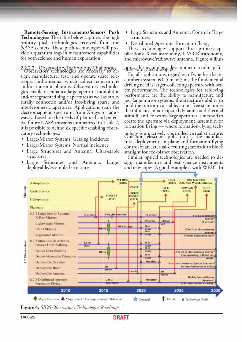
2.2.2.2. Observatory Technology ChallengesObservatory technologies are necessary to de-
sign, manuacture, test, and operate space tele-scopes and antenna, which collect, concentrateand/or transmit photons. Observatory technolo-gies enable or enhance large-aperture monolithicand/or segmented single apertures as well as struc-turally connected and/or ree-ying sparse andintererometric apertures. Applications span theelectromagnetic spectrum, rom X-rays to radio- waves. Based on the needs o planned and poten-tial uture NASA missions summarized in able 7,it is possible to dene six specic enabling obser-vatory technologies:• Large-Mirror Systems: Grazing incidence• Large-Mirror Systems: Normal incidence• Large Structures and Antenna: Ultra-stable
structures• Large Structures and Antenna: Large-
deployable/assembled structures
• Large Structures and Antenna: Control o largestructures
• Distributed Aperture: Formation ying Tese technologies support three primary ap-
plications: X-ray astronomy, UVOIR astronomy,and microwave/radiowave antenna. Figure 4 illus-
trates the technology-development roadmap orobservatory technologies.For all applications, regardless o whether the in-
cumbent system is 0.5 m or 5 m, the undamentaldriving need is larger-collecting aperture with bet-ter perormance. Te technologies or achieving perormance are the ability to manuacture andtest large-mirror systems; the structure’s ability tohold the mirror in a stable, strain-ree state underthe inuence o anticipated dynamic and thermalstimuli; and, or extra-large apertures, a method tocreate the aperture via deployment, assembly, orormation ying — where ormation-ying tech-
nology is an actively controlled virtual structure.One non-telescope application is the manuac-ture, deployment, in-plane and ormation-ying control o an external-occulting starshade to block starlight or exo-planet observation.
Similar optical technologies are needed to de-sign, manuacture and test science instrumentsand telescopes. A good example is with WFSC. In
Figure 4. SIOS Observatory Technologies Roadmap

7/30/2019 501624main Ta08 Sioss Draft Nov2010 A
http://slidepdf.com/reader/full/501624main-ta08-sioss-draft-nov2010-a 25/36
TA08-21DRAFT
Tchg dscpt
8.2 Observatories
Synthetic Aperture Imaging Lidar (SAIL) Synthetic Aperture Imaging Lidar (SAIL) for hyper-resolution imaging and 3D ranging (range imaging). SAILmethods could map dynamics of planetary surfaces on Mars (polar caps), Titan (moving landscapes), and evenon Europa much more eciently than current single beam or multi-beam approaches. SAIL may be a methodworth pursuing for ICESat-3 in the 2020’s to rapidly build up 3D geodetic maps of the ice covered surfaces of Earth
Super High-Resolution Imaging of
High-Energy Photons
The technology need is to build a large area (much larger than current optics) high energy optic and then have it
y it formation with the imaging spacecraft
Radar Arrays Wideband active electronically steered array radar with lightweighted antennae
Precision Interferometry Requires CW single-frequency and frequency-stabilized lasers for space (GSFC applications so far are pulsed).Digital techniques including coded modulation for time-of-ight resolvable interference, and exible in-ightchanges. Time-Domain Interferometry (LISA's equal-path-length synthesis techniques).
Hyper-Resoluti on Visible- NIR Hyper-resolution Visible- NIR imaging using lightweighte d optics in the 1-1.5m class (5 cm/pixel class)
K- Band R ada r Compa ct K- ba nd i ma gi ng an d soundi ng ra dar s (na dir an d si de look ing) f or pl an et ar y sci en ces (sma ll a nte nna e)
Conductive Carbon Nanotubes Spectacular new material for the fabrication of lightweight antennas could be enabled by the unbelievableconductivity of individual carbon nanotubes.
Deployable Large Aperture Telescopes Ultra low mass/volume large deployable large aperture telescopes (>2 meter) for direct detection LIDAR. Con-cepts include inatable fresnel, deployable reector and petal-based techniques.
High stability optical platforms Includes optical benches, telescopes, etc, requiring passive thermal isolation for temperature stability. Hydrox-ide or silicate bonding for precision alignment capability and dimensional stability. Precision materials such asSilicon Carbide and single crystal silicon, Zerodur
addition to being implemented inside the scienceinstruments, optical-component technologiesprovide eedback to operate the space telescope.Other important technologies include validatedperormance models that integrate optical, me-chanical, dynamic, and thermal models or tele-scopes, structures, instruments, and spacecrat.Tese technologies enable the design and man-uacture o observatories whose perormance re-quirements cannot be tested on the ground. An-other Push technology includes new materials toenable ultra-stable large space structures; tera-
bit communication; and autonomous rendezvousand docking or on-orbit assembly o very largestructures.
Chandra, HERO, FOXSI, XMM, and thesoon-to-be launched NuSAR currently denethe state o the art in X-ray astronomy. Pull re-quirements or X-ray astronomy are dened by IXO and FOXSI-3. Missions like Gen-X dene X-ray ‘push’ requirements. Hubble, JWS, andcommercial imaging systems, such as QuckBird,represent the state o the art in UVOIR. Pull re-quirements or UVOIR are dened by WFIRS,PF-C, and ALAS-8 or ALAS-9. Missions
like ALAS-16 dene push requirements or ex-tremely large space telescopes (ELS) in the 15- to30-m class range. GRIPS, ONEP, SWO, ACE,and SCLP represent uture pull requirements orantenna and booms.
Finally, the most important metric or all uturelarge telescopes must be cost per square meter o the collecting aperture. Assuming that total mis-sion budgets always will be limited to a ew bil-lion dollars, the only way to aford a larger tele-
scope is to reduce areal cost. Historically, a spacetelescope’s ination- adjusted cost has decreasedby 50% every 17 years. Investment is required toaccelerate this trend.
Observatories Push Technologies: Te tablebelow captures the high priority push technolo-gies received rom the NASA centers that ocusedmostly on large-area structures, telescopes, andantennas. Additionally, synthetic aperture devel-opment will be pushed to new levels as technolo-gy transitions to 3D range imaging. Observatory push technologies apply to Earth missions (LIS
and beyond), and to NEOs. Tese push technolo-gies will provide a quantum leap in measurementcapabilities or both science and human explora-tion.
2.2.2.3. In-Situ Instruments/SensorsTechnology Challenges
In-Situ Instruments/Sensors technologies enableor enhance a broad range o planned and poten-tial missions in the next two decades. Tese tech-nologies can be grouped into three general cate-gories that collect and/or sense: (1) charged andneutral particles; (2) magnetic and electric eldsand waves (e.g., gravity); and (3) chemical, min-eralogical, organic, and in-situ biological samples.echnologies related to the rst two categoriesare required or Astrophysics, Heliophysics, andPlanetary missions, while in-situ sampling tech-nologies are required only in support o planetary missions (none identied or Earth). able 8 sum-marizes the required sensor technologies or eachcategory, their current state o art, the needed per-ormance, and the type o missions that they will

7/30/2019 501624main Ta08 Sioss Draft Nov2010 A
http://slidepdf.com/reader/full/501624main-ta08-sioss-draft-nov2010-a 26/36
TA08-22 DRAFT
Table 7. Observatory Technology Challenges Tchg mtc Stt f at n Stt Trl6 mss
8 . 2 . 1
L a r g e M i r r o r S y s t e m s
8.2.1.1 Gzg icc
1 to 100 keV FWHM resolution 10 arcsec <5 arcsec 2011 2014 FOXSI-3
Aperture diameterFWHM resolutionAreal density; Areal cost
0.3 m2
15 arcsec10 kg/m2
>3 m2
<5 arcsec2011 2020 IXO
Aperture diameterFWHM angular resolutionAreal density (depends on LV)Active Control
0.3 m2
15 arcsec10 kg/m2 No
>50 m2
<1 arcsec1 kg/m2 (depend LV)Yes
2011 2030 Push,GenX
8.2.1.2 n icc
Size & polarizationAreal density
Planck,~20 kg/m2
1.6 m, <6 kg/m2 20112018
20202024
ITP,3DWinds
Aperture diameterFigureStability (dynamic & thermal)ReectivityAreal density (depends on LV)
Areal cost
2.4 m< 10 nm rms--->60%, 120-900nm240 kg/m2
$12M/m2
3 to 8 m<10 nm rms>9,000 min>60%, 90-900 nm20 (or 400) kg/m2
<$2M/m2
2011 2020 NWTP,UVOTP
Aperture diameterAreal density (depends on LV)Areal cost
6.5 m50 kg/m2 $6M/m2
15 to 30 m,5 (or 100) kg/m2,<$0.5M/m2
2030 Push,EL-ST
8 . 2 . 2
L a r g e S t r u c t u r e s & A n t e n n a
8.2.2.1 Pss ut-Stb Stcts
Thermal stability Chandra WFOV PSF Stability 2011 2014 WFIRST
Aperture diameterThermal/dynamic stabilityLine-of-sight jitter WFEAreal density (depends on LV)Areal cost
6.5 m60 nm rms1.6 mas40 kg/m2 $4 M/m2
8 m15 nm rms1 mas<20 (or 400) kg/m2 <$2 M/m2
2011 2020 NW/UVO
8.2.2.2 dpb/assb Tscp Sppt Stct at
Antenna apertureAntenna apertureSurface gure
5 m
1.5 mm rms
6 m> 10 m<0.1 mm rms
20132016
20192023
ACE, SCLP
Boom lengthStinessPointing stability
≥ 20 m107 N m2 0.005 arcsec roll/3 min
2011 2014 GRIPS,ONEP,SWOT
Occulter diameter Few cm 30 to 100 m 2011 2020 NWTP
Aperture diameter 6.5 m 8 m 2011 2020 NW/UVO
Aperture diameter 6.5 m 15 to 30 m 2030 EL-ST
8.2.2.3 act Ct
Occulter pedal controlOcculter modal controlBoom tip control
< 0.5 deg< 0.1 mm rms~0.5 deg
20112012
20202014
NWTP,GRIPS
Aperture diameterAperture diameterThermal/dynamic stabilityLine-of-Sight jitter WFEAreal density (depends on LV)Areal cost
6.5 m6.5 m60 nm rms1.6 mas40 kg/m2 $4 M/m2
8 m15 to 30 m15 nm rms1 mas<20 (or 400) kg/m2 <$2 M/m2
2011 20202030
NW/UVO,Push,EL-ST
8 . 2 . 3
D i s t r i b u t e d 8.2.3.1 Ft Fg
Range 10,000 to 80,000 km 2013 2016 LISA
Separation controlLateral alignmentRelative positionRelative pointing
2 m
5 cm rms6.7 arcmin rms
100 to 400 ±0.1 m±0.7 m wrt LOS< 1 cm rms< 1 ±0.1 arcsec
2011 201520242030
ONEP,Occulter,NWTP,Push
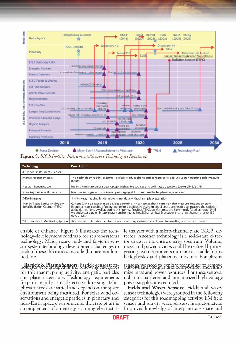
7/30/2019 501624main Ta08 Sioss Draft Nov2010 A
http://slidepdf.com/reader/full/501624main-ta08-sioss-draft-nov2010-a 27/36
TA08-23DRAFT
Figure 5. SIOS In-Situ Instruments/Sensors Technologies Roadmap
Tchg dscpt
8.3 In-Situ Instruments/Sensors
Atomic Magnetometers This technology has the potential to greatly reduce the resources required to execute vector magnetic eld measure-ments.
Neutron Spectroscopy In situ dynamic neutron spectroscopy with active sources and collimated detectors (beyond MSL’s DAN)
Scanning Electron Microscope In-situ scanning electron microscope imaging at 1 um and smaller for planetary surfaces
X-Ray Imaging In-situ X-ray imaging for denitive mineralogy without sample preparation
Human Tissue Equivalent Propor-tional Radiation Counter (TEPC)
Current SOA is a space station devices operating in near-atmospheric condition that measure dosages on crew.Robust sensors capable of operating for long periods in environment of space are needed to measure the radiationat the destination as well as during the journey. Previous TEPCs on Mars missions have mostly failed en-route. Untilwe get better data on interplanetary environment, the JSC human health group wants to limit human trips to 150days or less.
Tricorder Health Monitoring System As a related topic to humans in space, a monitoring system that will provide a reading of astronauts’ health.
enable or enhance. Figure 5 illustrates the tech-nology-development roadmap or sensor-systemstechnology. Major near-, mid- and ar-term sen-sor-system technology-development challenges ineach o these three areas include (but are not lim-ited to):
Particle & Plasma Sensors: Particle-sensor tech-nologies were grouped in the ollowing categoriesor this roadmapping activity: energetic particlesand plasma detectors. echnology requirementsor particle and plasma detectors addressing Helio-physics needs are varied and depend on the spaceenvironment being measured. For solar wind ob-servations and energetic particles in planetary andnear-Earth space environments, the state o art isa complement o an energy-scanning electrostat-
ic analyzer with a micro-channel plate (MCP) de-tector. Another technology is a solid-state detec-tor to cover the entire energy spectrum. Volume,mass, and power savings could be realized by inte-grating two instruments into one to enable utureheliophysics and planetary missions. For plasma
sensors, we need to explore techniques to removeout-o-band energies and composition and mini-mize mass and power resources. For these sensors,radiation-hardened and miniaturized high-voltagepower supplies are required.
Fields and Waves Sensors: Fields and wave-sensor technologies were grouped in the ollowing categories or this roadmapping activity: EM eldsensor and gravity wave sensors; magnetometers.Improved knowledge o interplanetary space and
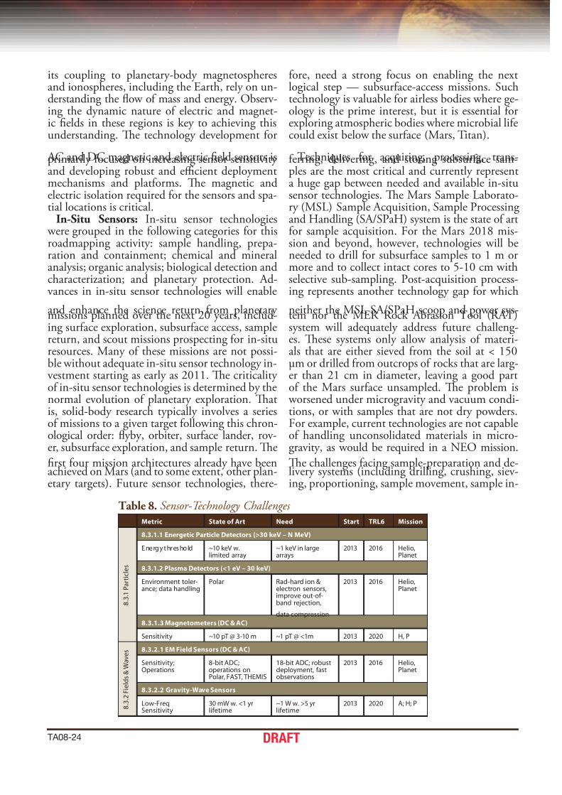
7/30/2019 501624main Ta08 Sioss Draft Nov2010 A
http://slidepdf.com/reader/full/501624main-ta08-sioss-draft-nov2010-a 28/36
TA08-24 DRAFT
its coupling to planetary-body magnetospheresand ionospheres, including the Earth, rely on un-derstanding the ow o mass and energy. Observ-ing the dynamic nature o electric and magnet-ic elds in these regions is key to achieving thisunderstanding. Te technology development or
AC and DC magnetic and electric eld sensors isprimarily ocused on increasing sensor sensitivity and developing robust and ecient deploymentmechanisms and platorms. Te magnetic andelectric isolation required or the sensors and spa-tial locations is critical.
In-Situ Sensors: In-situ sensor technologies were grouped in the ollowing categories or thisroadmapping activity: sample handling, prepa-ration and containment; chemical and mineralanalysis; organic analysis; biological detection andcharacterization; and planetary protection. Ad-vances in in-situ sensor technologies will enable
and enhance the science return rom planetary missions planned over the next 20 years, includ-ing surace exploration, subsurace access, samplereturn, and scout missions prospecting or in-situresources. Many o these missions are not possi-ble without adequate in-situ sensor technology in-vestment starting as early as 2011. Te criticality o in-situ sensor technologies is determined by thenormal evolution o planetary exploration. Tatis, solid-body research typically involves a serieso missions to a given target ollowing this chron-ological order: yby, orbiter, surace lander, rov-er, subsurace exploration, and sample return. Te
rst our mission architectures already have beenachieved on Mars (and to some extent, other plan-etary targets). Future sensor technologies, there-
ore, need a strong ocus on enabling the nextlogical step — subsurace-access missions. Suchtechnology is valuable or airless bodies where ge-ology is the prime interest, but it is essential orexploring atmospheric bodies where microbial liecould exist below the surace (Mars, itan).
echniques or acquiring, processing, trans-erring, delivering, and storing subsurace sam-ples are the most critical and currently representa huge gap between needed and available in-situsensor technologies. Te Mars Sample Laborato-ry (MSL) Sample Acquisition, Sample Processing and Handling (SA/SPaH) system is the state o artor sample acquisition. For the Mars 2018 mis-sion and beyond, however, technologies will beneeded to drill or subsurace samples to 1 m ormore and to collect intact cores to 5-10 cm withselective sub-sampling. Post-acquisition process-ing represents another technology gap or which
neither the MSL SA/SPaH scoop and power sys-tem nor the MER Rock Abrasion ool (RA)system will adequately address uture challeng-es. Tese systems only allow analysis o materi-als that are either sieved rom the soil at < 150µm or drilled rom outcrops o rocks that are larg-er than 21 cm in diameter, leaving a good parto the Mars surace unsampled. Te problem is worsened under microgravity and vacuum condi-tions, or with samples that are not dry powders.For example, current technologies are not capableo handling unconsolidated materials in micro-gravity, as would be required in a NEO mission.
Te challenges acing sample-preparation and de-livery systems (including drilling, crushing, siev-ing, proportioning, sample movement, sample in-
Table 8. Sensor-Technology Challenges mtc Stt f at n Stt Trl6 mss
8 . 3 . 1
P a r t i c l e s
8.3.1.1 egtc Ptc dtcts (>30 kv – n mv)
Energy threshold ~10 keV w.limited array
~1 keV in largearrays
2013 2016 Helio,Planet
8.3.1.2 Ps dtcts (<1 v – 30 kv)
Environment toler-ance; data handling
Polar Rad-hard ion &electron sensors,improve out-of-band rejection,
data compression
2013 2016 Helio,Planet
8.3.1.3 mgtts (dC & aC)
Sensitivity ~10 pT @ 3-10 m ~1 pT @ <1m 2013 2020 H, P
8 . 3 . 2
F i e l d s & W a v e s 8.3.2.1 em F Sss (dC & aC)
Sensitivity;Operations
8-bit ADC;operations onPolar, FAST, THEMIS
18-bit ADC; robustdeployment, fastobservations
2013 2016 Helio,Planet
8.3.2.2 Gt-w Sss
Low-FreqSensitivity
30 mW w. <1 yrlifetime
~1 W w. >5 yrlifetime
2013 2020 A; H; P

7/30/2019 501624main Ta08 Sioss Draft Nov2010 A
http://slidepdf.com/reader/full/501624main-ta08-sioss-draft-nov2010-a 29/36
TA08-25DRAFT
mtc Stt f at n Stt Trl6 ms-s
8 . 3 . 3
I n - S i t u
8.3.4.1 Sp Hg, Ppt, Ctt
Sample acquisition MSL: SA/SPaHExoMar: drill
Subsurface drilling ≥1 m; intact cores 5-10cm length
2011 2014-2016
Planet
Sampl e pre pa ra ti on MSL: SA /SPa H; MER:RAT; ExoMars: jawcrusher
Core sub-sampling;powdering for XRD,GC-MS
2011 2016 Planet
Sample transfer anddelivery
MSL: Dry powderaliquot transfer w. <5% contamination ingravity atm.
Transfer of varioussample types (pow-der, ice) under manyconditions (µG, vac.)
2011 2016 Planet
Sample temperaturecontrol
Limited temperaturecontrol
Cryogenic & sealing,preserve volatilecomponents
2011 2018 Planet
Contamination &sample integrity
Phoenix: pre-launchsteril. & cruise biobar-rier; MSL: samplechamber clean.
Sample control &monitor for <0.1%cross-contamination
2011 2018 Planet
8.3.4.2 Chc m asssst (B aPxS)
Wet chem. (pH, eH) &dissolved solids
Phoenix WCL Measure sample drywt., dissolved ions to1 ppm
2011 2016 Planet
Elemental composition(LIBS, XRF)
MSL XRD/XRF: wholesample analysis;component- limitedperformance, 0.5 wt%elemental separation
Spatial resolved XRFw. lat res ~10 µm;High e. XR tubes;time-gated detect;0.1 wt%, low atomic# (<18) capabilit y
2011 2016 Planet
Mineralogy (Raman,XRD, IR and UV spec-trometers)
MSL CheMin: detectlimit few wt%; ExoMarsRaman w. 10s µmimagery/analysis
Detect limit <1 wt%;reection modeXRD wo/ sampleprep; spatially resol.Raman
2011 2016 Planet
Microscopy MSL MAHLI: 15µm res;Phoenix MECA: 4µm/pix clr
SEM imaging w. 10nm res;Hyperspectral micro
imaging
2011 2020 Planet
8.3.4.3 ogc asssst (B inmS)
Detection sensitivity &contamination
Phoenix: ppb sensitiv-ity with ppm contami-nation
ppb sensitivity; non-thermal methods,contamin. preven-tion
2011 2017 Planet
Mass range & resolution Cassini INMS: Range:100 AMU; Res: 0.1 AMU
Range: >100 AMU;Resolution: <0.1 AMU
2011 2019 Planet
8.3.4.4 Bgc dtct & Chctzt
Biomarker detection &characterization
Characterize viableorganisms that areculturable; terrestrialcontamin > detectionlimits
Biomarkers quantita-tive assessmentw. ppb sensitivity;terrestrial contamprevention
2011 2016 Planet
Complex OrganicPolymer
ExoMars ppb sensitivity 2011 2016 Planet
8.3.4.5 Pt Ptct (PP)
Organism detection(sensitivity/breadth)
Characterization of viable organisms thatare culturable
Characterization of any viable organism
2013 2016 Planet
System & componentsterilization
DHMR sterile w. detect< sterile; ppb organiccontamin
DHMR & e-beamirrad w. detection ≥sterilization level
2013 2016 Planet

7/30/2019 501624main Ta08 Sioss Draft Nov2010 A
http://slidepdf.com/reader/full/501624main-ta08-sioss-draft-nov2010-a 30/36
TA08-26 DRAFT
sertion, etc.) create a need or sensors (like XRD/ XRF) that can analyze samples without post-ac-quisition preparation and delivery. Tese like-ly would be arm-based in-situ sensors that wouldnot require sample insertion, reducing the needor complicated acquisition and handling systems.
Such sensor development represents a technology push that would broaden the range o easible sub-surace access missions. echnology gaps also existor sample post-delivery, including those that en-able temperature control during containment andstorage. Te technology is required to preserve icy or volatile components and enable control andmonitoring o contained samples to limit cross-contamination to less than 0.1%.
Other in-situ sensor-technology challenges oruture missions include techniques in chemicaland mineral assessment, organic analysis, biolog-ical detection and characterization, and planetary
protection. Te state o art or each and neededtechnology advances are summarized in able 8.In-Situ Instruments/ Sensors Push Technolo-
gies: Push technology inputs provided by NASA’scenters ocused mostly on adapting geophysicalanalytical techniques or use on NEOs, planets,and other planetary targets o opportunity.
3. inTerdePendenCy wiTHoTHer TeCHnoloGy areaS
SIOSS technologies have direct, indirect, andgame changing interdependencies with all the oth-er technology areas (able 9). Tese interdepen-dencies ow both ways. A direct interdependen-cy is one where a technology development in onearea enables or enhances another area to achieveits perormance metrics. An indirect interdepen-dency is one where a development in another area changes the need or or the metric requirement ortechnology. A game changing interdependency isone where a breakthrough in another area enablesa desired but previously inconceivable mission.
Examples o direct interdependencies o SIOSStechnology impacting other technology areas (A)include long-lived high-power lasers and single
photon detectors or optical communication; largeaperture deployable solar concentrators or spacepower and solar thermal propulsions; machine vi-sion systems to aid human and autonomous op-erations ranging rom the assembly o ight hard- ware to AR&D to 3D terrain descent imaging. A common theme or many A areas was advancedintegrated health monitoring sensors or appli-cations ranging rom jet engines, to launch vehi-cles to human health systems and non-destructive
evaluation instruments. Sensor systems are criti-cal to many navigation needs, including orma-tion ying — both in space and commercially. Ex-amples o indirect interdependencies include: how eedback rom planetary science missions mightmodiy requirements o human-rated planetary
mission vehicles and systems; how Earth sciencedata might modiy requirements or commercialaviation systems or terrestrial launch operations. A potential game changing SIOSS technology is a quantum-entangled optical comb clock to enablea deep space positioning system.
Examples o direct interdependencies o how other technology impacts SIOSS includes milli-Newton and micro-Newton thrusters, drag-reepropulsion control, and accelerometers that en-able advanced gravitation sensors; robotic systemsthat enable various planetary in-situ sensing; new materials or extreme environments such as Venus
or itan, nano-technology or new miniaturizedbiological or chemical sensors; or sub-20K cryo-coolers or inrared to ar-inrared optical systemsand detectors. Examples o other A technologiesrequired to enable SIOSS technology missionsinclude downlink communication o terabits o data; solar sails to reach and maintain orbits; de-scent systems, and aero-capture systems. Poten-tial game changing technologies include a sharedpower and communication inrastructure at Sun-Earth L2; in-space robotic servicing; or human as-sisted in-space assembly.
O particular interest was the interaction be-
tween the SIOSS team and the Human Explora-tion Destination Systems (HEDS) eam. HEDStechnology requirements include improved sen-sors and instrumentation or characterizing desti-nation sites. Included in this assessment are thosetechnologies needed or macro characterization o the destination target, including sensors incorpo-rated onto a space-based observatory and thoseneeded or in-situ characterization, including sen-sors on a robotic precursor or early crewed mis-sion. While SIOSS concentrated primarily on SMD
applications (astrophysics, Earth, heliophysicsand planetary science), the technology is applica-ble to the entirety o NASA missions. able 9 de-tails how SIOSS technology can enable applica-tions related to other NASA mission directorates.
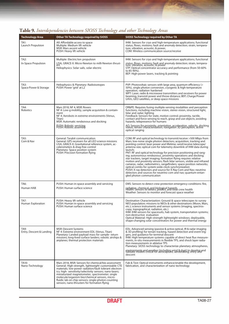
7/30/2019 501624main Ta08 Sioss Draft Nov2010 A
http://slidepdf.com/reader/full/501624main-ta08-sioss-draft-nov2010-a 31/36
TA08-27DRAFT
Tchg a oth Ta Tchg q b SioSS SioSS Tchg q b oth Ta
TA1:Launch Propulsion
All: Aordable access to spaceMultiple: Medium lift vehicleMSR: Mars ascent vehiclePUSH: Heavy lift vehicle
IHM: Sensors for cryo and high-temperature applications; functionalstatus, ows, motions; fault and anomaly detection; strain, tempera-ture, vibration, acoustic; & power,COM: Wireless communication source/receive
TA2:
In-Space Propulsion
Multiple: Electric/ion propulsion
LISA, GRACE-II: Micro-Newton to milli-Newton thrust-ersHeliophysics: Solar sails, solar electric
IHM: Sensors for cryo and high-temperature applications; functional
status, ows, motions; fault and anomaly detection; strain, tempera-ture, vibration, acoustic; & powerSTP: Optical concentrator accuracy and performance (from 50-60%to 85-90%).BEP: High-power lasers, tracking & pointing
TA3:Space Power & Storage
Heliophysics & Planetary: RadioisotopesPUSH: Power ‘grid’ at L2
PVP: Photovoltaic sensors with large area, quantum eciency (>50%), single photon conversion, cryogenic & high-temperatureoperation, radiation hardenedWPT: Laser, radio & microwave transmitters and receivers for powerbeaming, transmit power and throw distance; BEP; Charge/PowerUAVs, GEO satellites, or deep space missions
TA4:Robotics
Mars 2018, NF 4, MSR: RoversNF 4: Low-g mobility, sample acquisition & contain-mentNF 4: Aerobots in extreme environments (Venus,Titan)MSR: Automatic rendezvous and docking
PUSH: Robotic servicingPUSH: Robotic assembly
OR&PE: Requires fusing multiple-sensing modalities and perceptionfunctions, including machine vision, stereo vision, structured light,lidar and radar; lightingFeedback: Sensors for state, motion control; proximity, tactile,contact and force sensing to reach, grasp and use objects; avoidinghazards; telepresence for humans
AO: Sensors for proximity, orientation, acceleration, velocity, dockingstatus; terrain characterization; navigation 3D perception, activeoptical ranging
TA5:Com & Nav
General: Terabit communicationGeneral: GPS receivers for all LEO science missionsLISA, GRACE-II: Gravitational reference system, ac-celerometers & drag-free controlPlanetary: Space position systemPUSH: Precision formation ying
COM: RF and optical technology to transmit/receive >500 Mbps fromMars; low-noise single photon detectors; acquisition, tracking andpointing control; laser power and lifetime; send/receive telescope/antenna size; optical com for telemetry downlink of IHM data duringlaunch;PNT: RF and optical technology for precision positioning and rang-ing; autonomous rendezvous, proximity operations and docking;star trackers, target imaging; formation ying requires relativemotion and proximity sensors; ash lidar sensors, visible and infraredcameras, radar, radiometrics, rangenders; space position networks;optical combs for system-wide clock synchronizationPUSH: X-ray detectors and source for X-Ray Com and Nav; neutrinodetectors and sources for neutrino com and nav; quantum-entan-gled photon communication
TA6:
Human HAB
PUSH: Human in-space assembly and servicing
PUSH: Human surface science
EMS: Sensors to detect crew-protection emergency conditions: re,
radiation, chemical, and biological hazardsHealth: Sensors to detect, predict, and treat crew healthWeather: Sensors to monitor and forecast space weather
TA7:Human Exploration
PUSH: Heavy lift vehiclePUSH: Human in-space assembly and servicingPUSH: Human surface science
Destination Characterization: Ground & space telescopes to surveyNEO population; missions to NEOs & other destinations (Moon, Mars,etc.); science instruments and sensor systems (imaging, spectros-copy, topographical, radiation, etc.)IHM: IHM sensors for spacesuits, hab system, transportation systems;non-destructive evaluationOptical Material: High-strength lightweight windows; deployable,shape-changing solar concentrators for power and thermal energy
TA9:Entry, Descent & Landing
MSR: Descent SystemsNF 4: Extreme environment EDL (Venus, Titan)Planetary: Landed payload mass for sample- returnmissions; long-lived surface landers; robotic airships &airplanes; thermal protection materials
EDL: Advanced sensing (passive & active optical, IR & radar imaging& 3D proling) for terrain tracking, hazard detection and event trig-gers, and guidance for terminal descentIHM: High-temperature systems capable of direct heat ux measure-ments, in-situ measurements in exible TPS, and shock layer radia-tion measurements in ablative TPSPlanetary: SIOSS technology to characterize planetary atmospheres,
environments and weather (including wind & dust) to develop andvalidate models critical for aerocapture, aerobraking, entry anddescent
TA10:Nano-Technology
Mars 2018, MSR: Sensors for chemical/bio assessmentGeneral: High-strength, lightweight customizable CTEmaterials; low-power radiation/fault tolerant electron-ics; high- sensitivity/selectivity sensors; nano-lasers;miniaturized magnetometer, spectrometer; singlemolecule/organism bio/chemical sensors, micro-uidic lab on chip sensors; single-photon countingsensors; nano-thrusters for formation ying
Fab & Test: Optical instruments enhance/enable the development,fabrication, and characterization of nano technology
Table 9. Interdependencies between SIOSS Technology and other Technology Areas

7/30/2019 501624main Ta08 Sioss Draft Nov2010 A
http://slidepdf.com/reader/full/501624main-ta08-sioss-draft-nov2010-a 32/36
TA08-28 DRAFT
Tchg a oth Ta Tchg q b SioSS SioSS Tchg q b oth Ta
TA11:Modeling
General: Validated performance modeling for obser-vatories, instruments, and spacecraft that integrateoptical, structural, dynamic and thermal modelsMSR: Entry, descent, landing & launch systems inte-grated modeling & simulationDiscovery 14, NF 4: Small body encountersGeneral: Model-based systems engineering; inte-grated high-delity multi-scale multi-physics-basedperformance modeling
General: SIOSS technology to acquire data to validate multi-physicsmodels for space and Earth weather needed for simulation delity
TA12:Materials & Structures
PUSH: Low-density, high stiness, low-CTE materials;large, deployable or assembly, active or passive, ultra-sti/stable, precision structuresNF 4: Extreme environments (Venus, Titan)General: Mechanisms, hinges, docking, and interfaces;optical component materials
NDE: Perform NDE performance characterization for model-basedcertication and sustainment methods; dimensional and positionalcharacterizationIHM: Embedded sensors to characterize structure state, perfor-mance, and life assessmentOptical: Materials and designs are required for low-scatter, high-strength damage-tolerant lightweight habitat windows
TA13:Ground/Launch Sys
PUSH: Ability to integrate very large science missions IHM: Sensors for real-time in-situ measurements to reduce/eliminateover-purging practices; corrosion detection; anomalous conditionsmonitoring, toxic leaks, safetyState Sensing: Sensors and vision systems to aid in ight hardwareassembly; NDE structural integrity inspection; wireless or opticalnetworks to access or transmit large quantities of safety data andinformationOperations: Advanced telemetry communication systems, high-datarate laser/optical com; visual and electronic range trackingWeather: SIOSS technology to acquire data to quantify and predictweather
TA14:Thermal Management
IXO: Sub-20K Cryo-CoolersMSR: Thermal Management of Mars Ascent VehicleGeneral: Low power cryocoolers (35K, 10-6K, and 2K);passive and active precision thermal control
Radiators: Optical emissivity coatings
4. PoSSiBle BeneFiTS TooTHer naTional needS
All SIOSS technologies will benet a range o national needs. Currently, NASA Earth Sciencemissions are typically developed collaboratively with theother national agencies. Observatory and
science-instrument technologies are common-ly used by multiple communities, includingtheintelligence community, and commercial imag-ing companies. Te primary diference betweenNASA and other potential beneciaries is thetechnology’s operating environment. For exam-ple, astrophysics and astronomical detectors/ocalplanes have similar low-noise sensitivity require-ments but diferent operating environments, suchas radiation hardness. A similar comparison canbe made between planetary or heliophysics in-si-tu sensors and those used on the battleeld, in a hospital, at port and border checkpoints, or in a meat packing plant. X-ray mirror technology canbe applied to commercial X-ray microscopes, X-ray lithography, or synchrotron optics. Space mi-crowave, radar, or Hz imaging systems can beapplied to numerous government and industri-al applications, or example, lidar/DIAL remote-sensing technology has applications ranging romcloud diagnostics to smoke stack pollution com-pliance.

7/30/2019 501624main Ta08 Sioss Draft Nov2010 A
http://slidepdf.com/reader/full/501624main-ta08-sioss-draft-nov2010-a 33/36
TA08-29DRAFT
aCronymS ACE Aerosol/Cloud/Ecosystems
ADC Analog to Digital Converter
AMU Atomic Mass Unit
AO Autonomous Operation
APD Avalanche Diodes
APIO Advanced Planning and Integration Ofce AR&D Autonomous Rendezvous and Docking
ASCENDS Active Sensing of CO2
Emissions overNights, Days, and Seasons
ASIC Application Specic Integrated Circuit
ATLAST Advanced Technology Large Aperture Space Telescope
APXS Alpha Particle X-Ray Spectrometer
AU Astronomical Units
BEP Beamed Energy Propulsion
CCD Charged Coupled Device
CheMin Chemical Mineral Instrument
CISR Climate Impacts of Space Radiation
COM CommunicationsCW Continuous Wave
DIAL Differential Absorption Lidar
DGC Dynamic Geospace Coupling
DHMR Dry Heat Microbial Reduction
EDL Entry, Descent and Landing
EJSM Europa-Jupiter System Mission
ELST Extremely Large Space Telescopes
EM Electromagnetic
EMS Environmental Monitoring and Safety
FAST Fast Auroral SnapshoT
FOV Field of View
FOXSI Focusing Optics X-ray Solar Imager
FPA Focal Plane ArrayFWHM Full Width Half Maximum
GACM Global Atmospheric Composition Mission
GC-MS Gas Chromatography-MassSpectroscopy
GenX Generation-X Vision
GEO Geosynchronous Orbit
GEO-CAPE Geostationary Coastal and AirPollution Events
GPS Global Positioning Satellite
GRACE Gravity Recovery and ClimateExperiment
GRIPS Gamma-Ray Imager/Polarimeter for Solar
HEDS Human Exploration Destination SystemsHERO High-Energy Replicated Optics
HiRISE High Resolution Imaging ScienceExperiment
HMaG Heliospheric Magnetics
HyspIRI Hyperspectral Infrared Imager
Hz Hertz
IHM Integrated Health Management
InGaAs Indium Gallium Arsenide
INMS Ion and Neutral Mass Spectrometer
INCA Ion-Neutral Coupling in the Atmosphere
ITP Ination Technology Program
IXO International X-ray Observatory
JAXA Japanese Aerospace and Exploration Agency
LCAS Low-Cost Access to Space
LIBS Laser-Induced Breakdown Spectroscopy
LIMA Long-range laser Induced Mass Analysis
LISA Laser Interferometer Space Antenna
LIST Lidar Surface Topography
LROC Lunar Reconnaissance Orbiter Camera
MAHLI Mars Hand Lens Imager
MCP Microchannel Plate
Mdeg Millidegree
MECA Microscopy, Electrochemistry, and
Conductivity Analyzer
MER Mars Exploration Rovers
MKIDS Microwave Kinetic Inductance Detectors
MSL Mars Science Lab
MSR Mars Sample ReturnNDE Non-Destructive Evaluation
NEO Near Earth Object
NEP Noise Equivalent Power
NF New Frontiers
NIR Near Infrared
NRC National Research Council
NuSTAR Nuclear Spectroscopic Telescope Array
NW New Worlds
O Optical
ONSET Origins of Near Earth Plasma
OR&PE Object Recognition and Pose Estimation
PATH Precipitation and All Weather Temperature
and HumidityPNT Position, Navigation, and Timing
PRF Pulse Repetition Frequency
PSF Point Spread Function
PVP Photovoltaic Power
QE Quantum Efciency
RAT Rock Abrasion Tool
RFI Radio Frequency Interference
ROIC Readout Integrated Circuit
SAIL Synthetic Aperture Imaging Lidar
SAR Synthetic Aperture Radar
SA/SPaH Sample Acquisition / Sample Processingand Handling
SCLP Snow and Cold Land ProcessesSEM Scanning Electron Microscope
SEM Space Experiment Module
SEPAT Solar Energetic Particle Acceleration andTransport
SEU/SEL Single Event Upset/Single EventLatchup
SIOSS Science Instruments, Observatories, andSensor Systems
SMD Science Mission Directorate

7/30/2019 501624main Ta08 Sioss Draft Nov2010 A
http://slidepdf.com/reader/full/501624main-ta08-sioss-draft-nov2010-a 34/36
TA08-30 DRAFT
SPICA Science Investigation Concept Studies
SSE Solar System Exploration
STP Solar Thermal Propulsion
SWOT Surface Water and Ocean Topography
TABS Technology Area Breakdown Structure
TEPC Tissue Equivalent Proportional RadiationCounter
TES Transition Edge Sensors
THEMIS Time History of Events and MacroscaleInteractions during Substorms
THz TeraHertz
TID Total Ionizing Dose
TIR Total Internal Reection
TPF-C Terrestrial Planet Finder-Coronagraph
TPS Thermal Protection System
T/R Transmitter/Receiver
UAV Unmanned Aerial Vehicle
UV Ultraviolet
UVOIR UV-Optical-near IR
VIS VisibleWCL Wet Chemistry Laboratory
WFE Wall Plug Efciency
WFOV Wide Field of View
WFIRST Wide-Field Infrared Survey Telescope
WFSC Wavefront Sensing and Control
WINCS Wind Ion-drift Neutral-ion Composition
WPT Wireless Power Transmission
XMM X-ray Multi-Mirror Mission
XRD X-Ray Diffraction
XRF X-ray Fluorescence
aCKnowledGemenTSTe NASA technology area drat roadmaps
were developed with the support and guidancerom the Oce o the Chie echnologist. In ad-dition to the primary authors, major contribu-tors or the A08 HEDS roadmap included theOC A08 Roadmapping POC, Karen McNa-mara; the reviewers provided by the NASA CenterChie echnologists and NASA Mission Director-ate representatives, and the ollowing individuals:David Blake, Chris McKay, George Komar, Azita Valinia, Jim Spann, and Chris Webster.

7/30/2019 501624main Ta08 Sioss Draft Nov2010 A
http://slidepdf.com/reader/full/501624main-ta08-sioss-draft-nov2010-a 35/36
TA08-31DRAFT
is page is intentionally left blank

7/30/2019 501624main Ta08 Sioss Draft Nov2010 A
http://slidepdf.com/reader/full/501624main-ta08-sioss-draft-nov2010-a 36/36
November 2010
National Aeronautics and
Space Administration
NASA Headquarters
Washington, DC 20546