Embed Size (px)
Citation preview
Report Number: F690501/RF-RTL009890-2 Page: 70 of 97
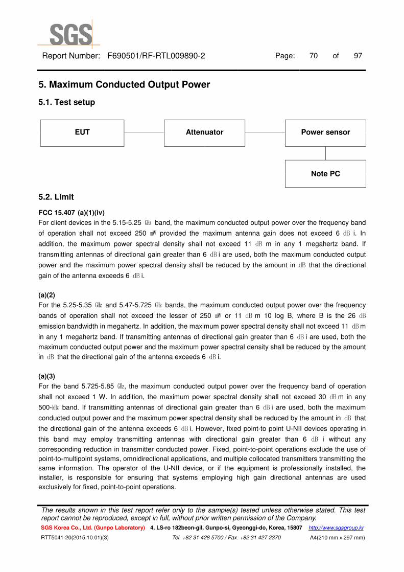
5. Maximum Conducted Output Power
5.1. Test setup
EUT Attenuator Power sensor
Note PC
5.2. Limit
FCC 15.407 (a)(1)(iv)
For client devices in the 5.15-5.25 ㎓ band, the maximum conducted output power over the frequency band
of operation shall not exceed 250 ㎽ provided the maximum antenna gain does not exceed 6 ㏈ i. In
addition, the maximum power spectral density shall not exceed 11 ㏈ m in any 1 megahertz band. If
transmitting antennas of directional gain greater than 6 ㏈ i are used, both the maximum conducted output
power and the maximum power spectral density shall be reduced by the amount in ㏈ that the directional
gain of the antenna exceeds 6 ㏈ i.
(a)(2)
For the 5.25-5.35 ㎓ and 5.47-5.725 ㎓ bands, the maximum conducted output power over the frequency
bands of operation shall not exceed the lesser of 250 ㎽ or 11 ㏈ m 10 log B, where B is the 26 ㏈
emission bandwidth in megahertz. In addition, the maximum power spectral density shall not exceed 11 ㏈m
in any 1 megahertz band. If transmitting antennas of directional gain greater than 6 ㏈ i are used, both the
maximum conducted output power and the maximum power spectral density shall be reduced by the amount
in ㏈ that the directional gain of the antenna exceeds 6 ㏈ i.
(a)(3)
For the band 5.725-5.85 ㎓, the maximum conducted output power over the frequency band of operation
shall not exceed 1 W. In addition, the maximum power spectral density shall not exceed 30 ㏈ m in any
500-㎑ band. If transmitting antennas of directional gain greater than 6 ㏈ i are used, both the maximum
conducted output power and the maximum power spectral density shall be reduced by the amount in ㏈ that
the directional gain of the antenna exceeds 6 ㏈ i. However, fixed point-to point U-NII devices operating in
this band may employ transmitting antennas with directional gain greater than 6 ㏈ i without any
corresponding reduction in transmitter conducted power. Fixed, point-to-point operations exclude the use of
point-to-multipoint systems, omnidirectional applications, and multiple collocated transmitters transmitting the
same information. The operator of the U-NII device, or if the equipment is professionally installed, the
installer, is responsible for ensuring that systems employing high gain directional antennas are used
exclusively for fixed, point-to-point operations.
The results shown in this test report refer only to the sample(s) tested unless otherwise stated. This test report cannot be reproduced, except in full, without prior written permission of the Company.
SGS Korea Co., Ltd. (Gunpo Laboratory) 4, LS-ro 182beon-gil, Gunpo-si, Gyeonggi-do, Korea, 15807 http://www.sgsgroup.kr
RTT5041-20(2015.10.01)(3) Tel. +82 31 428 5700 / Fax. +82 31 427 2370 A4(210 mmⅹ297 mm)

Report Number: F690501/RF-RTL009890-2 Page: 71 of 97
5.3. Test procedure
1. This measurement settings are specified in section E.3.a of KDB 789033_D02 v01r02.
2. Measurements may be performed using a wideband RF power meter with a thermocouple detector or
equivalent if all of the conditions listed below are satisfied.
- The EUT is configured to transmit continuously or to transmit with a consistent duty cycle.
- At all times when the EUT is transmitting, it must be transmitting at its maximum power control level.
- The integration period of the power meter exceeds the repetition period of the transmitted signal by at
least a factor of five.
3. If the transmitter does not transmit continuously, measure the duty cycle, x, of the transmitter output signal
as described in section II.B.
4. Measure the average power of the transmitter. This measurement is an average over both the on and off
periods of the transmitter.
5. Adjust the measurement in ㏈ m by adding 10 log (1/x) where x is the duty cycle (e.g., 10 log(1/0.25) if the
duty cycle is 25 percent).
6. In case of band crossing channels 144, the measurement is complied with section E.2.d of KDB
789033_D02 v01r02 and section D of KDB 644545_D03 v01.
The results shown in this test report refer only to the sample(s) tested unless otherwise stated. This test report cannot be reproduced, except in full, without prior written permission of the Company.
SGS Korea Co., Ltd. (Gunpo Laboratory) 4, LS-ro 182beon-gil, Gunpo-si, Gyeonggi-do, Korea, 15807 http://www.sgsgroup.kr
RTT5041-20(2015.10.01)(3) Tel. +82 31 428 5700 / Fax. +82 31 427 2370 A4(210 mmⅹ297 mm)
Report Number: F690501/RF-RTL009890-2 Page: 72 of 97
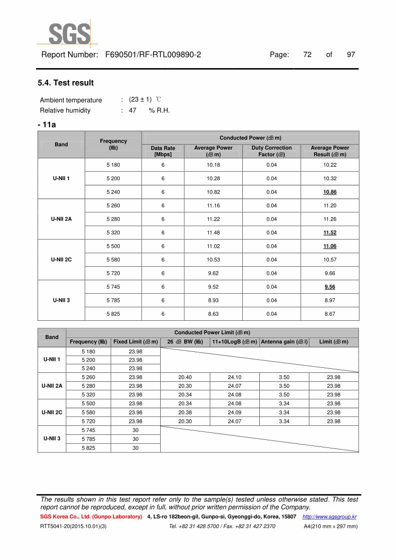
5.4. Test result
Ambient temperature : (23 ± 1) ℃
Relative humidity : 47 % R.H.
- 11a
Band Frequency
(㎒)
Conducted Power (㏈m)
Data Rate [Mbps]
Average Power
(㏈m)
Duty Correction
Factor (㏈)
Average Power
Result (㏈m)
U-NII 1
5 180 6 10.18 0.04 10.22
5 200 6 10.28 0.04 10.32
5 240 6 10.82 0.04 10.86
U-NII 2A
5 260 6 11.16 0.04 11.20
5 280 6 11.22 0.04 11.26
5 320 6 11.48 0.04 11.52
U-NII 2C
5 500 6 11.02 0.04 11.06
5 580 6 10.53 0.04 10.57
5 720 6 9.62 0.04 9.66
U-NII 3
5 745 6 9.52 0.04 9.56
5 785 6 8.93 0.04 8.97
5 825 6 8.63 0.04 8.67
Band Conducted Power Limit (㏈m)
Frequency (㎒) Fixed Limit (㏈m) 26 ㏈ BW (㎒) 11+10LogB (㏈m) Antenna gain (㏈ i) Limit (㏈m)
U-NII 1
5 180 23.98
5 200 23.98
5 240 23.98
U-NII 2A
5 260 23.98 20.40 24.10 3.50 23.98
5 280 23.98 20.30 24.07 3.50 23.98
5 320 23.98 20.34 24.08 3.50 23.98
U-NII 2C
5 500 23.98 20.34 24.08 3.34 23.98
5 580 23.98 20.38 24.09 3.34 23.98
5 720 23.98 20.30 24.07 3.34 23.98
U-NII 3
5 745 30
5 785 30
5 825 30
The results shown in this test report refer only to the sample(s) tested unless otherwise stated. This test report cannot be reproduced, except in full, without prior written permission of the Company.
SGS Korea Co., Ltd. (Gunpo Laboratory) 4, LS-ro 182beon-gil, Gunpo-si, Gyeonggi-do, Korea, 15807 http://www.sgsgroup.kr
RTT5041-20(2015.10.01)(3) Tel. +82 31 428 5700 / Fax. +82 31 427 2370 A4(210 mmⅹ297 mm)

Report Number: F690501/RF-RTL009890-2 Page: 73 of 97
- 11n_HT20
Band Frequency
(㎒)
Conducted Power (㏈m)
Data Rate [Mbps]
Average Power
(㏈m)
Duty Correction
Factor (㏈)
Average Power
Result (㏈m)
U-NII 1
5 180 MCS0 9.58 0.04 9.62
5 200 MCS0 9.76 0.04 9.80
5 240 MCS0 10.01 0.04 10.05
U-NII 2A
5 260 MCS0 10.29 0.04 10.33
5 280 MCS0 10.36 0.04 10.40
5 320 MCS0 10.61 0.04 10.65
U-NII 2C
5 500 MCS0 10.11 0.04 10.15
5 580 MCS0 9.72 0.04 9.76
5 720 MCS0 9.65 0.04 9.69
U-NII 3
5 745 MCS0 8.63 0.04 8.67
5 785 MCS0 8.00 0.04 8.04
5 825 MCS0 7.87 0.04 7.91
Band Conducted Power Limit (㏈m)
Frequency (㎒) Fixed Limit (㏈m) 26 ㏈ BW (㎒) 11+10LogB (㏈m) Antenna gain (㏈ i) Limit (㏈m)
U-NII 1
5 180 23.98
5 200 23.98
5 240 23.98
U-NII 2A
5 260 23.98 20.48 24.11 3.50 23.98
5 280 23.98 20.50 24.12 3.50 23.98
5 320 23.98 20.46 24.11 3.50 23.98
U-NII 2C
5 500 23.98 20.50 24.12 3.34 23.98
5 580 23.98 20.46 24.11 3.34 23.98
5 720 23.98 20.50 24.12 3.34 23.98
U-NII 3
5 745 30
5 785 30
5 825 30
The results shown in this test report refer only to the sample(s) tested unless otherwise stated. This test report cannot be reproduced, except in full, without prior written permission of the Company.
SGS Korea Co., Ltd. (Gunpo Laboratory) 4, LS-ro 182beon-gil, Gunpo-si, Gyeonggi-do, Korea, 15807 http://www.sgsgroup.kr
RTT5041-20(2015.10.01)(3) Tel. +82 31 428 5700 / Fax. +82 31 427 2370 A4(210 mmⅹ297 mm)
Report Number: F690501/RF-RTL009890-2 Page: 74 of 97
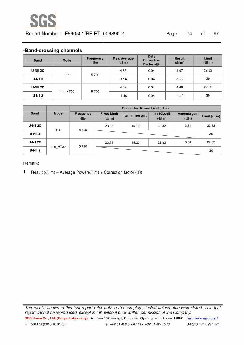
-Band-crossing channels
Band Mode Frequency
(㎒)
Mea. Average
(㏈m)
Duty Correction
Factor (㏈)
Result
(㏈m)
Limit
(㏈m)
U-NII 2C
11a 5 720
4.63 0.04 4.67 22.82
U-NII 3 -1.96 0.04 -1.92 30
U-NII 2C
11n_HT20 5 720
4.62 0.04 4.66 22.83
U-NII 3 -1.46 0.04 -1.42 30
Band Mode
Conducted Power Limit (㏈m)
Frequency
(㎒)
Fixed Limit
(㏈m) 26 ㏈ BW (㎒)
11+10LogB
(㏈m)
Antenna gain
(㏈ i) Limit (㏈m)
U-NII 2C
11a 5 720 23.98 15.19 22.82 3.34 22.82
U-NII 3 30
U-NII 2C
11n_HT20 5 720 23.98 15.23 22.83 3.34 22.83
U-NII 3 30
Remark:
1. Result (㏈ m) = Average Power(㏈ m) + Correction factor (㏈)
The results shown in this test report refer only to the sample(s) tested unless otherwise stated. This test report cannot be reproduced, except in full, without prior written permission of the Company.
SGS Korea Co., Ltd. (Gunpo Laboratory) 4, LS-ro 182beon-gil, Gunpo-si, Gyeonggi-do, Korea, 15807 http://www.sgsgroup.kr
RTT5041-20(2015.10.01)(3) Tel. +82 31 428 5700 / Fax. +82 31 427 2370 A4(210 mmⅹ297 mm)

Report Number: F690501/RF-RTL009890-2 Page: 75 of 97
Band-crossing channels
802.11a (5 720 ㎒)
802.11n_HT20 (5 720 ㎒)
The results shown in this test report refer only to the sample(s) tested unless otherwise stated. This test report cannot be reproduced, except in full, without prior written permission of the Company.
SGS Korea Co., Ltd. (Gunpo Laboratory) 4, LS-ro 182beon-gil, Gunpo-si, Gyeonggi-do, Korea, 15807 http://www.sgsgroup.kr
RTT5041-20(2015.10.01)(3) Tel. +82 31 428 5700 / Fax. +82 31 427 2370 A4(210 mmⅹ297 mm)
Report Number: F690501/RF-RTL009890-2 Page: 76 of 97
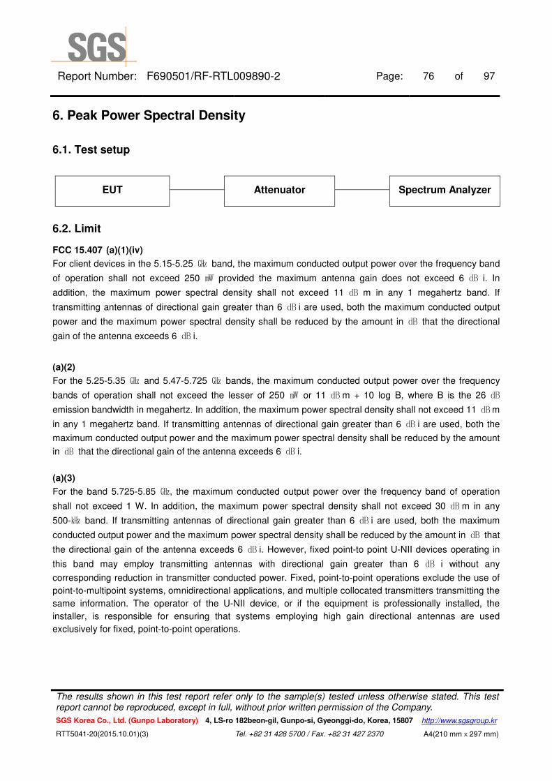
6. Peak Power Spectral Density
6.1. Test setup
EUT Attenuator Spectrum Analyzer
6.2. Limit
FCC 15.407 (a)(1)(iv)
For client devices in the 5.15-5.25 ㎓ band, the maximum conducted output power over the frequency band
of operation shall not exceed 250 ㎽ provided the maximum antenna gain does not exceed 6 ㏈ i. In
addition, the maximum power spectral density shall not exceed 11 ㏈ m in any 1 megahertz band. If
transmitting antennas of directional gain greater than 6 ㏈ i are used, both the maximum conducted output
power and the maximum power spectral density shall be reduced by the amount in ㏈ that the directional
gain of the antenna exceeds 6 ㏈ i.
(a)(2)
For the 5.25-5.35 ㎓ and 5.47-5.725 ㎓ bands, the maximum conducted output power over the frequency
bands of operation shall not exceed the lesser of 250 ㎽ or 11 ㏈ m + 10 log B, where B is the 26 ㏈
emission bandwidth in megahertz. In addition, the maximum power spectral density shall not exceed 11 ㏈m
in any 1 megahertz band. If transmitting antennas of directional gain greater than 6 ㏈ i are used, both the
maximum conducted output power and the maximum power spectral density shall be reduced by the amount
in ㏈ that the directional gain of the antenna exceeds 6 ㏈ i.
(a)(3)
For the band 5.725-5.85 ㎓, the maximum conducted output power over the frequency band of operation
shall not exceed 1 W. In addition, the maximum power spectral density shall not exceed 30 ㏈ m in any
500-㎑ band. If transmitting antennas of directional gain greater than 6 ㏈ i are used, both the maximum
conducted output power and the maximum power spectral density shall be reduced by the amount in ㏈ that
the directional gain of the antenna exceeds 6 ㏈ i. However, fixed point-to point U-NII devices operating in
this band may employ transmitting antennas with directional gain greater than 6 ㏈ i without any
corresponding reduction in transmitter conducted power. Fixed, point-to-point operations exclude the use of
point-to-multipoint systems, omnidirectional applications, and multiple collocated transmitters transmitting the
same information. The operator of the U-NII device, or if the equipment is professionally installed, the
installer, is responsible for ensuring that systems employing high gain directional antennas are used
exclusively for fixed, point-to-point operations.
The results shown in this test report refer only to the sample(s) tested unless otherwise stated. This test report cannot be reproduced, except in full, without prior written permission of the Company.
SGS Korea Co., Ltd. (Gunpo Laboratory) 4, LS-ro 182beon-gil, Gunpo-si, Gyeonggi-do, Korea, 15807 http://www.sgsgroup.kr
RTT5041-20(2015.10.01)(3) Tel. +82 31 428 5700 / Fax. +82 31 427 2370 A4(210 mmⅹ297 mm)
Report Number: F690501/RF-RTL009890-2 Page: 77 of 97
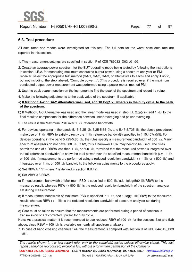
6.3. Test procedure
All data rates and modes were investigated for this test. The full data for the worst case data rate are
reported in this section.
1. This measurement settings are specified in section F of KDB 789033_D02 v01r02.
2. Create an average power spectrum for the EUT operating mode being tested by following the instructions
in section II.E.2. for measuring maximum conducted output power using a spectrum analyzer or EMI
receiver: select the appropriate test method (SA-1, SA-2, SA-3, or alternatives to each) and apply it up to,
but not including, the step labeled, “Compute power…”. (This procedure is required even if the maximum
conducted output power measurement was performed using a power meter, method PM.)
3. Use the peak search function on the instrument to find the peak of the spectrum and record its value.
4. Make the following adjustments to the peak value of the spectrum, if applicable:
a) If Method SA-2 or SA-2 Alternative was used, add 10 log(1/x), where x is the duty cycle, to the peak
of the spectrum.
b) If Method SA-3 Alternative was used and the linear mode was used in step II.E.2.g)(viii), add 1 ㏈ to the
final result to compensate for the difference between linear averaging and power averaging.
5. The result is the Maximum PSD over 1 ㎒ reference bandwidth.
6. For devices operating in the bands 5.15-5.25 ㎓, 5.25-5.35 ㎓, and 5.47-5.725 ㎓, the above procedures
make use of 1 ㎒ RBW to satisfy directly the 1 ㎒ reference bandwidth specified in § 15.407(a)(5). For
devices operating in the band 5.725-5.85 ㎓, the rules specify a measurement bandwidth of 500 ㎑. Many
spectrum analyzers do not have 500 ㎑ RBW, thus a narrower RBW may need to be used. The rules
permit the use of a RBWs less than 1 ㎒, or 500 ㎑, “provided that the measured power is integrated over
the full reference bandwidth” to show the total power over the specified measurement bandwidth (i.e., 1 ㎒,
or 500 ㎑). If measurements are performed using a reduced resolution bandwidth (< 1 ㎒, or < 500 ㎑) and
integrated over 1 ㎒, or 500 ㎑ bandwidth, the following adjustments to the procedures apply:
a) Set RBW ≥ 1/T, where T is defined in section II.B.l.a).
b) Set VBW ≥ 3 RBW.
c) If measurement bandwidth of Maximum PSD is specified in 500 ㎑, add 10log(500 ㎑/RBW) to the
measured result, whereas RBW (< 500 ㎑) is the reduced resolution bandwidth of the spectrum analyzer
set during measurement.
d) If measurement bandwidth of Maximum PSD is specified in 1 ㎒, add 10log(1 ㎒/RBW) to the measured
result, whereas RBW (< 1 ㎒) is the reduced resolution bandwidth of spectrum analyzer set during
measurement.
e) Care must be taken to ensure that the measurements are performed during a period of continuous
transmission or are corrected upward for duty cycle.
Note: As a practical matter, it is recommended to use reduced RBW of 100 ㎑ for the sections 5.c) and 5.d)
above, since RBW = 100 ㎑ is available on nearly all spectrum analyzers.
7. In case of band crossing channels 144, the measurement is complied with section D of KDB 644545_D03
v01.
The results shown in this test report refer only to the sample(s) tested unless otherwise stated. This test report cannot be reproduced, except in full, without prior written permission of the Company.
SGS Korea Co., Ltd. (Gunpo Laboratory) 4, LS-ro 182beon-gil, Gunpo-si, Gyeonggi-do, Korea, 15807 http://www.sgsgroup.kr
RTT5041-20(2015.10.01)(3) Tel. +82 31 428 5700 / Fax. +82 31 427 2370 A4(210 mmⅹ297 mm)
Report Number: F690501/RF-RTL009890-2 Page: 78 of 97
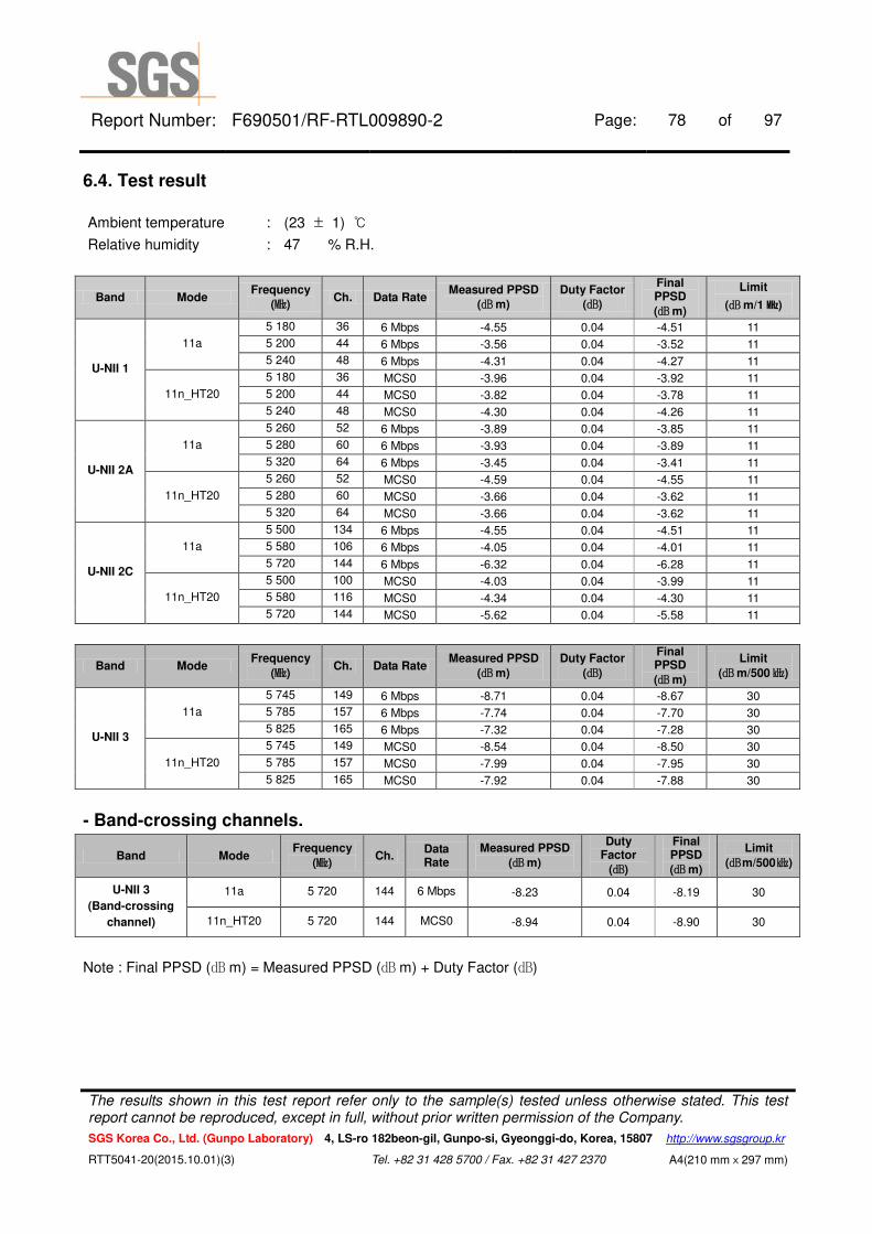
6.4. Test result
Ambient temperature : (23 ± 1) ℃
Relative humidity : 47 % R.H.
Band Mode Frequency
(㎒) Ch. Data Rate
Measured PPSD
(㏈m)
Duty Factor
(㏈)
Final PPSD
(㏈m)
Limit
(㏈m/1㎒)
U-NII 1
11a
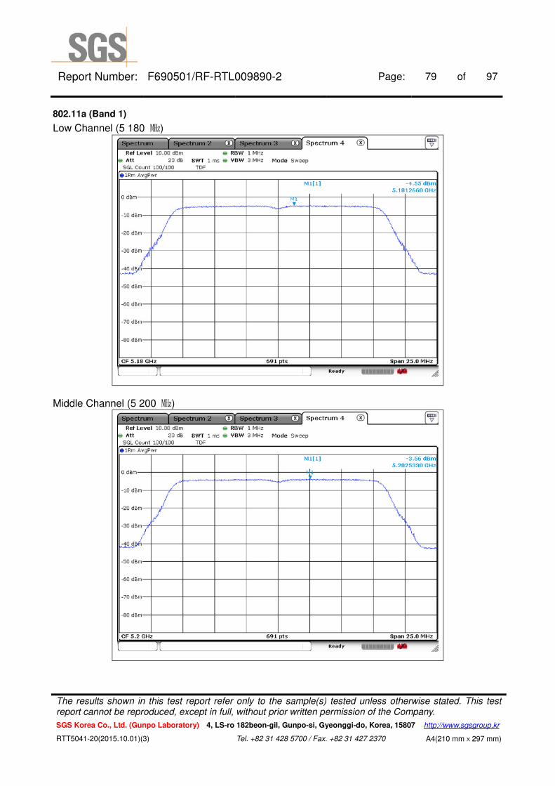
5 180 36 6 Mbps -4.55 0.04 -4.51 11
5 200 44 6 Mbps -3.56 0.04 -3.52 11
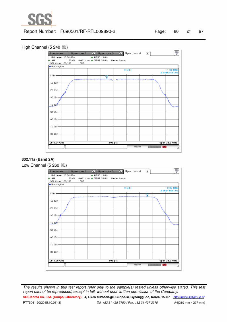
5 240 48 6 Mbps -4.31 0.04 -4.27 11
11n_HT20
5 180 36 MCS0 -3.96 0.04 -3.92 11
5 200 44 MCS0 -3.82 0.04 -3.78 11
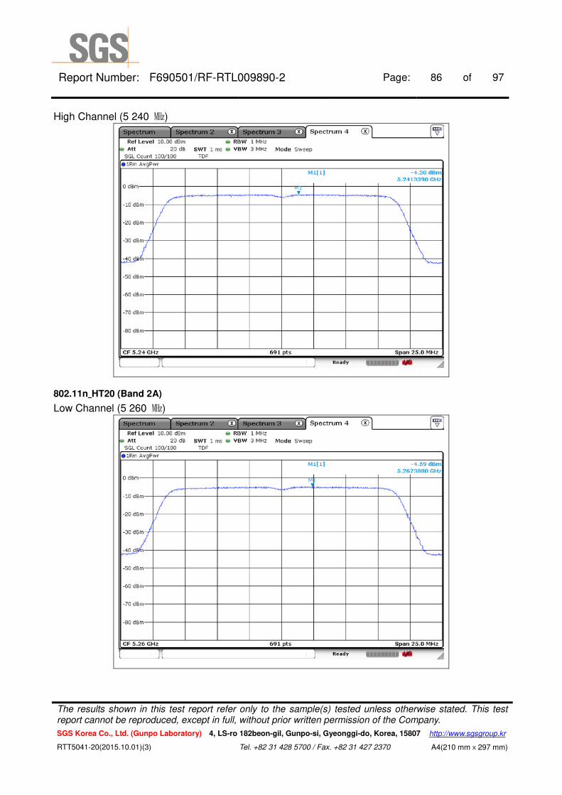
5 240 48 MCS0 -4.30 0.04 -4.26 11
U-NII 2A
11a
5 260 52 6 Mbps -3.89 0.04 -3.85 11
5 280 60 6 Mbps -3.93 0.04 -3.89 11
5 320 64 6 Mbps -3.45 0.04 -3.41 11
11n_HT20
5 260 52 MCS0 -4.59 0.04 -4.55 11
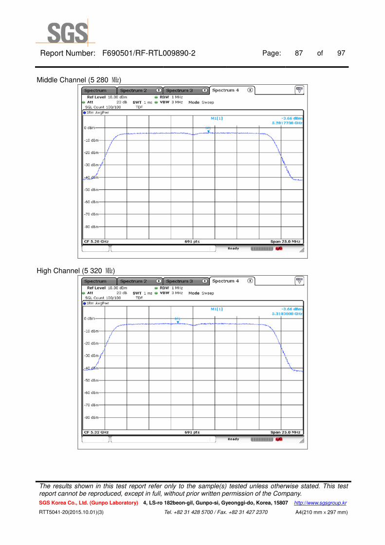
5 280 60 MCS0 -3.66 0.04 -3.62 11
5 320 64 MCS0 -3.66 0.04 -3.62 11
U-NII 2C
11a
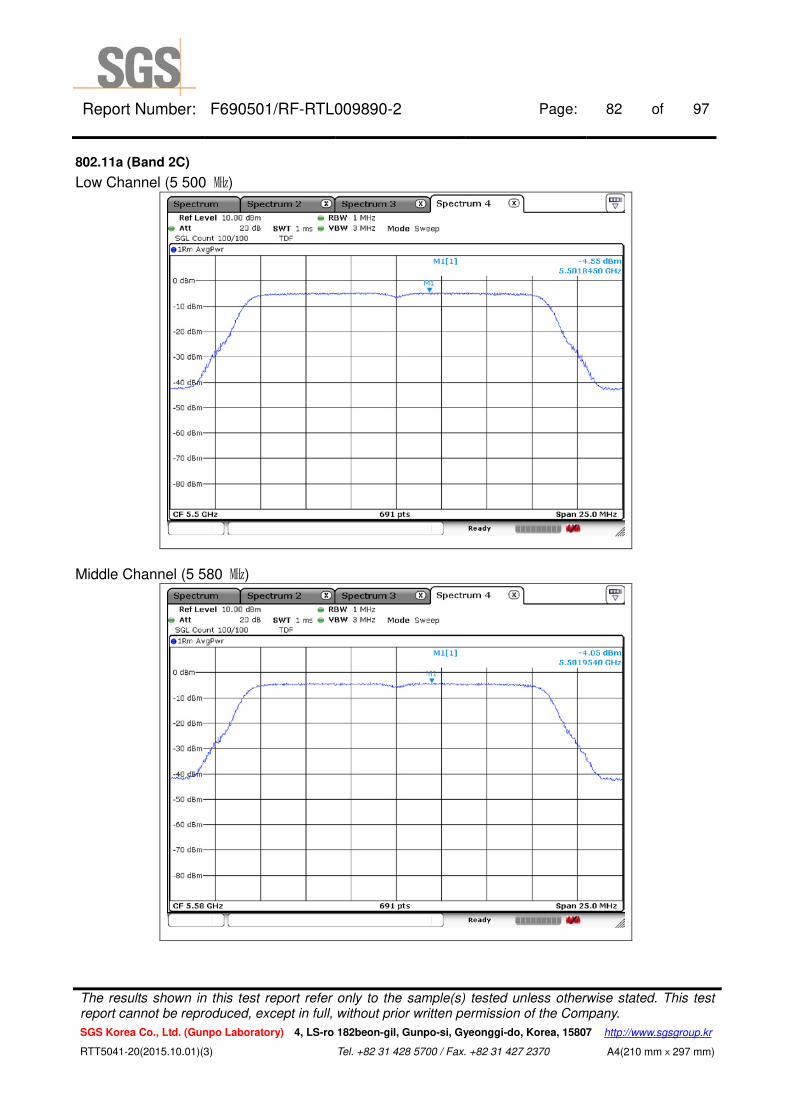
5 500 134 6 Mbps -4.55 0.04 -4.51 11
5 580 106 6 Mbps -4.05 0.04 -4.01 11
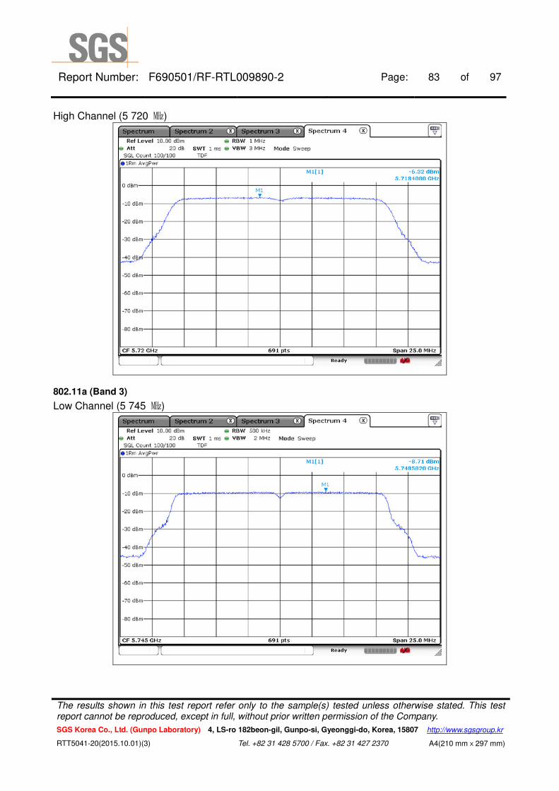
5 720 144 6 Mbps -6.32 0.04 -6.28 11
11n_HT20
5 500 100 MCS0 -4.03 0.04 -3.99 11
5 580 116 MCS0 -4.34 0.04 -4.30 11
5 720 144 MCS0 -5.62 0.04 -5.58 11
Band Mode Frequency
(㎒) Ch. Data Rate
Measured PPSD
(㏈m)
Duty Factor
(㏈)
Final PPSD
(㏈m)
Limit
(㏈m/500㎑)
U-NII 3
11a
5 745 149 6 Mbps -8.71 0.04 -8.67 30
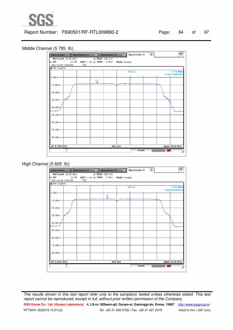
5 785 157 6 Mbps -7.74 0.04 -7.70 30
5 825 165 6 Mbps -7.32 0.04 -7.28 30
11n_HT20
5 745 149 MCS0 -8.54 0.04 -8.50 30
5 785 157 MCS0 -7.99 0.04 -7.95 30
5 825 165 MCS0 -7.92 0.04 -7.88 30
- Band-crossing channels.
Band Mode Frequency
(㎒) Ch.
Data Rate
Measured PPSD
(㏈m)
Duty Factor
(㏈)
Final PPSD
(㏈m)
Limit
(㏈m/500㎑)
U-NII 3
(Band-crossing
channel)
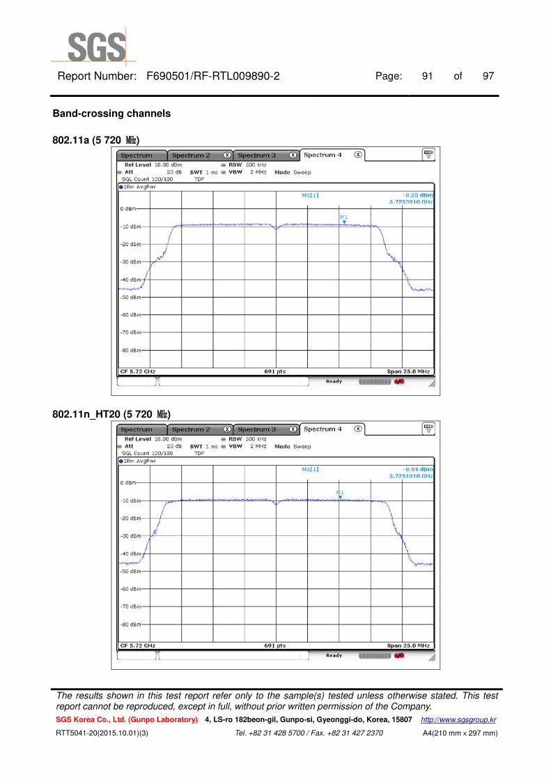
11a 5 720 144 6 Mbps -8.23 0.04 -8.19 30
11n_HT20 5 720 144 MCS0 -8.94 0.04 -8.90 30
Note : Final PPSD (㏈ m) = Measured PPSD (㏈ m) + Duty Factor (㏈)
The results shown in this test report refer only to the sample(s) tested unless otherwise stated. This test report cannot be reproduced, except in full, without prior written permission of the Company.
SGS Korea Co., Ltd. (Gunpo Laboratory) 4, LS-ro 182beon-gil, Gunpo-si, Gyeonggi-do, Korea, 15807 http://www.sgsgroup.kr
RTT5041-20(2015.10.01)(3) Tel. +82 31 428 5700 / Fax. +82 31 427 2370 A4(210 mmⅹ297 mm)
Report Number: F690501/RF-RTL009890-2 Page: 79 of 97
802.11a (Band 1)
Low Channel (5 180 ㎒)
Middle Channel (5 200 ㎒)
The results shown in this test report refer only to the sample(s) tested unless otherwise stated. This test report cannot be reproduced, except in full, without prior written permission of the Company.
SGS Korea Co., Ltd. (Gunpo Laboratory) 4, LS-ro 182beon-gil, Gunpo-si, Gyeonggi-do, Korea, 15807 http://www.sgsgroup.kr
RTT5041-20(2015.10.01)(3) Tel. +82 31 428 5700 / Fax. +82 31 427 2370 A4(210 mmⅹ297 mm)
Report Number: F690501/RF-RTL009890-2 Page: 80 of 97
High Channel (5 240 ㎒)
802.11a (Band 2A)
Low Channel (5 260 ㎒)
The results shown in this test report refer only to the sample(s) tested unless otherwise stated. This test report cannot be reproduced, except in full, without prior written permission of the Company.
SGS Korea Co., Ltd. (Gunpo Laboratory) 4, LS-ro 182beon-gil, Gunpo-si, Gyeonggi-do, Korea, 15807 http://www.sgsgroup.kr
RTT5041-20(2015.10.01)(3) Tel. +82 31 428 5700 / Fax. +82 31 427 2370 A4(210 mmⅹ297 mm)

Report Number: F690501/RF-RTL009890-2 Page: 81 of 97
Middle Channel (5 280 ㎒)
High Channel (5 320 ㎒)
The results shown in this test report refer only to the sample(s) tested unless otherwise stated. This test report cannot be reproduced, except in full, without prior written permission of the Company.
SGS Korea Co., Ltd. (Gunpo Laboratory) 4, LS-ro 182beon-gil, Gunpo-si, Gyeonggi-do, Korea, 15807 http://www.sgsgroup.kr
RTT5041-20(2015.10.01)(3) Tel. +82 31 428 5700 / Fax. +82 31 427 2370 A4(210 mmⅹ297 mm)
Report Number: F690501/RF-RTL009890-2 Page: 82 of 97
802.11a (Band 2C)
Low Channel (5 500 ㎒)
Middle Channel (5 580 ㎒)
The results shown in this test report refer only to the sample(s) tested unless otherwise stated. This test report cannot be reproduced, except in full, without prior written permission of the Company.
SGS Korea Co., Ltd. (Gunpo Laboratory) 4, LS-ro 182beon-gil, Gunpo-si, Gyeonggi-do, Korea, 15807 http://www.sgsgroup.kr
RTT5041-20(2015.10.01)(3) Tel. +82 31 428 5700 / Fax. +82 31 427 2370 A4(210 mmⅹ297 mm)
Report Number: F690501/RF-RTL009890-2 Page: 83 of 97
High Channel (5 720 ㎒)
802.11a (Band 3)
Low Channel (5 745 ㎒)
The results shown in this test report refer only to the sample(s) tested unless otherwise stated. This test report cannot be reproduced, except in full, without prior written permission of the Company.
SGS Korea Co., Ltd. (Gunpo Laboratory) 4, LS-ro 182beon-gil, Gunpo-si, Gyeonggi-do, Korea, 15807 http://www.sgsgroup.kr
RTT5041-20(2015.10.01)(3) Tel. +82 31 428 5700 / Fax. +82 31 427 2370 A4(210 mmⅹ297 mm)
Report Number: F690501/RF-RTL009890-2 Page: 84 of 97
Middle Channel (5 785 ㎒)
High Channel (5 825 ㎒)
The results shown in this test report refer only to the sample(s) tested unless otherwise stated. This test report cannot be reproduced, except in full, without prior written permission of the Company.
SGS Korea Co., Ltd. (Gunpo Laboratory) 4, LS-ro 182beon-gil, Gunpo-si, Gyeonggi-do, Korea, 15807 http://www.sgsgroup.kr
RTT5041-20(2015.10.01)(3) Tel. +82 31 428 5700 / Fax. +82 31 427 2370 A4(210 mmⅹ297 mm)

Report Number: F690501/RF-RTL009890-2 Page: 85 of 97
802.11n_HT20 (Band 1)
Low Channel (5 180 ㎒)
Middle Channel (5 200 ㎒)
The results shown in this test report refer only to the sample(s) tested unless otherwise stated. This test report cannot be reproduced, except in full, without prior written permission of the Company.
SGS Korea Co., Ltd. (Gunpo Laboratory) 4, LS-ro 182beon-gil, Gunpo-si, Gyeonggi-do, Korea, 15807 http://www.sgsgroup.kr
RTT5041-20(2015.10.01)(3) Tel. +82 31 428 5700 / Fax. +82 31 427 2370 A4(210 mmⅹ297 mm)
Report Number: F690501/RF-RTL009890-2 Page: 86 of 97
High Channel (5 240 ㎒)
802.11n_HT20 (Band 2A)
Low Channel (5 260 ㎒)
The results shown in this test report refer only to the sample(s) tested unless otherwise stated. This test report cannot be reproduced, except in full, without prior written permission of the Company.
SGS Korea Co., Ltd. (Gunpo Laboratory) 4, LS-ro 182beon-gil, Gunpo-si, Gyeonggi-do, Korea, 15807 http://www.sgsgroup.kr
RTT5041-20(2015.10.01)(3) Tel. +82 31 428 5700 / Fax. +82 31 427 2370 A4(210 mmⅹ297 mm)
Report Number: F690501/RF-RTL009890-2 Page: 87 of 97
Middle Channel (5 280 ㎒)
High Channel (5 320 ㎒)
The results shown in this test report refer only to the sample(s) tested unless otherwise stated. This test report cannot be reproduced, except in full, without prior written permission of the Company.
SGS Korea Co., Ltd. (Gunpo Laboratory) 4, LS-ro 182beon-gil, Gunpo-si, Gyeonggi-do, Korea, 15807 http://www.sgsgroup.kr
RTT5041-20(2015.10.01)(3) Tel. +82 31 428 5700 / Fax. +82 31 427 2370 A4(210 mmⅹ297 mm)

Report Number: F690501/RF-RTL009890-2 Page: 88 of 97
802.11n_HT20 (Band 2C)
Low Channel (5 500 ㎒)
Middle Channel (5 580 ㎒)
The results shown in this test report refer only to the sample(s) tested unless otherwise stated. This test report cannot be reproduced, except in full, without prior written permission of the Company.
SGS Korea Co., Ltd. (Gunpo Laboratory) 4, LS-ro 182beon-gil, Gunpo-si, Gyeonggi-do, Korea, 15807 http://www.sgsgroup.kr
RTT5041-20(2015.10.01)(3) Tel. +82 31 428 5700 / Fax. +82 31 427 2370 A4(210 mmⅹ297 mm)

Report Number: F690501/RF-RTL009890-2 Page: 89 of 97
High Channel (5 720 ㎒)
802.11n_HT20 (Band 3)
Low Channel (5 745 ㎒)
The results shown in this test report refer only to the sample(s) tested unless otherwise stated. This test report cannot be reproduced, except in full, without prior written permission of the Company.
SGS Korea Co., Ltd. (Gunpo Laboratory) 4, LS-ro 182beon-gil, Gunpo-si, Gyeonggi-do, Korea, 15807 http://www.sgsgroup.kr
RTT5041-20(2015.10.01)(3) Tel. +82 31 428 5700 / Fax. +82 31 427 2370 A4(210 mmⅹ297 mm)

Report Number: F690501/RF-RTL009890-2 Page: 90 of 97
Middle Channel (5 785 ㎒)
High Channel (5 825 ㎒)
The results shown in this test report refer only to the sample(s) tested unless otherwise stated. This test report cannot be reproduced, except in full, without prior written permission of the Company.
SGS Korea Co., Ltd. (Gunpo Laboratory) 4, LS-ro 182beon-gil, Gunpo-si, Gyeonggi-do, Korea, 15807 http://www.sgsgroup.kr
RTT5041-20(2015.10.01)(3) Tel. +82 31 428 5700 / Fax. +82 31 427 2370 A4(210 mmⅹ297 mm)
Report Number: F690501/RF-RTL009890-2 Page: 91 of 97
Band-crossing channels
802.11a (5 720 ㎒)
802.11n_HT20 (5 720 ㎒)
The results shown in this test report refer only to the sample(s) tested unless otherwise stated. This test report cannot be reproduced, except in full, without prior written permission of the Company.
SGS Korea Co., Ltd. (Gunpo Laboratory) 4, LS-ro 182beon-gil, Gunpo-si, Gyeonggi-do, Korea, 15807 http://www.sgsgroup.kr
RTT5041-20(2015.10.01)(3) Tel. +82 31 428 5700 / Fax. +82 31 427 2370 A4(210 mmⅹ297 mm)
Report Number: F690501/RF-RTL009890-2 Page: 92 of 97
7. AC Power Line Conducted Emissions
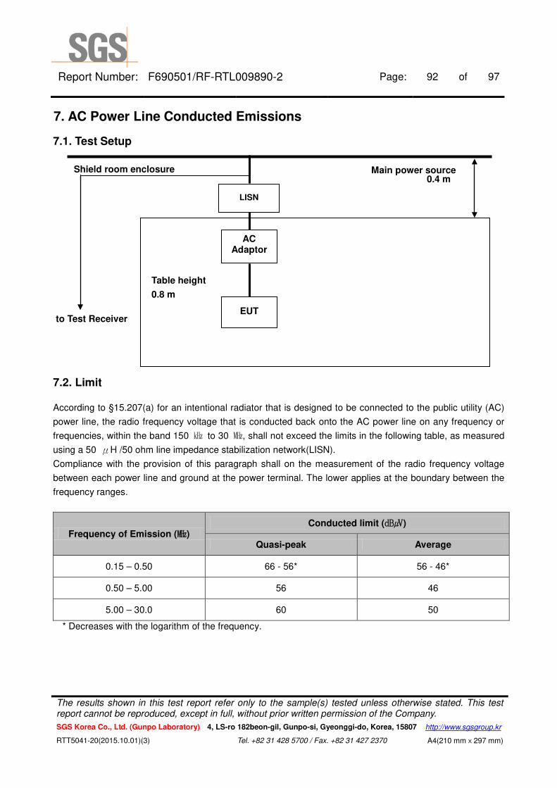
7.1. Test Setup
7.2. Limit
According to §15.207(a) for an intentional radiator that is designed to be connected to the public utility (AC)
power line, the radio frequency voltage that is conducted back onto the AC power line on any frequency or
frequencies, within the band 150 ㎑ to 30 ㎒, shall not exceed the limits in the following table, as measured
using a 50 μH /50 ohm line impedance stabilization network(LISN).
Compliance with the provision of this paragraph shall on the measurement of the radio frequency voltage
between each power line and ground at the power terminal. The lower applies at the boundary between the
frequency ranges.
Frequency of Emission (㎒) Conducted limit (㏈㎶)
Quasi-peak Average
0.15 – 0.50 66 - 56* 56 - 46*
0.50 – 5.00 56 46
5.00 – 30.0 60 50
* Decreases with the logarithm of the frequency.
Main power source Shield room enclosure
to Test Receiver
Table height
0.8 m
0.4 m
LISN
AC Adaptor
EUT
The results shown in this test report refer only to the sample(s) tested unless otherwise stated. This test report cannot be reproduced, except in full, without prior written permission of the Company.
SGS Korea Co., Ltd. (Gunpo Laboratory) 4, LS-ro 182beon-gil, Gunpo-si, Gyeonggi-do, Korea, 15807 http://www.sgsgroup.kr
RTT5041-20(2015.10.01)(3) Tel. +82 31 428 5700 / Fax. +82 31 427 2370 A4(210 mmⅹ297 mm)
Report Number: F690501/RF-RTL009890-2 Page: 93 of 97
7.3. Test Procedures All data rates and modes were investigated for this test. The full data for the worst case data rate are reported in this section.
AC line conducted emissions from the EUT were measured according to the dictates of ANSI C63.10-2013
1. The test procedure is performed in a 6.5 m × 3.6 m × 3.6 m (L × W × H) shielded room. The EUT along
with its peripherals were placed on a 1.0 m (W) × 1.5 m (L) and 0.8 m in height wooden table and the EUT
was adjusted to maintain a 0.4 meter space from a vertical reference plane.
2. The EUT was connected to power mains through a line impedance stabilization network (LISN) which
provides 50 ohm coupling impedance for measuring instrument and the chassis ground was bounded to
the horizontal ground plane of shielded room.
3. The excess power cable between the EUT and the LISN was bundled. All connecting cables of EUT were
moved to find the maximum emission.
The results shown in this test report refer only to the sample(s) tested unless otherwise stated. This test report cannot be reproduced, except in full, without prior written permission of the Company.
SGS Korea Co., Ltd. (Gunpo Laboratory) 4, LS-ro 182beon-gil, Gunpo-si, Gyeonggi-do, Korea, 15807 http://www.sgsgroup.kr
RTT5041-20(2015.10.01)(3) Tel. +82 31 428 5700 / Fax. +82 31 427 2370 A4(210 mmⅹ297 mm)
Report Number: F690501/RF-RTL009890-2 Page: 94 of 97
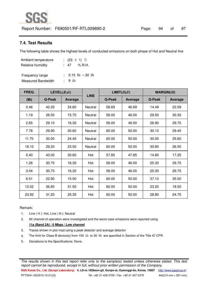
7.4. Test Results The following table shows the highest levels of conducted emissions on both phase of Hot and Neutral line
Ambient temperature : (23 ± 1) ℃
Relative humidity : 47 % R.H.
Frequency range : 0.15 ㎒ – 30 ㎒
Measured Bandwidth : 9 ㎑
FREQ. LEVEL(㏈㎶) LINE
LIMIT(㏈㎶) MARGIN(㏈)
(㎒) Q-Peak Average Q-Peak Average Q-Peak Average
0.46 42.20 24.60 Neutral 56.69 46.69 14.49 22.09
1.19 26.50 15.70 Neutral 56.00 46.00 29.50 30.30
2.65 29.10 16.30 Neutral 56.00 46.00 26.90 29.70
7.78 29.90 20.60 Neutral 60.00 50.00 30.10 29.40
11.70 30.00 24.40 Neutral 60.00 50.00 30.00 25.60
18.10 29.20 23.50 Neutral 60.00 50.00 30.80 26.50
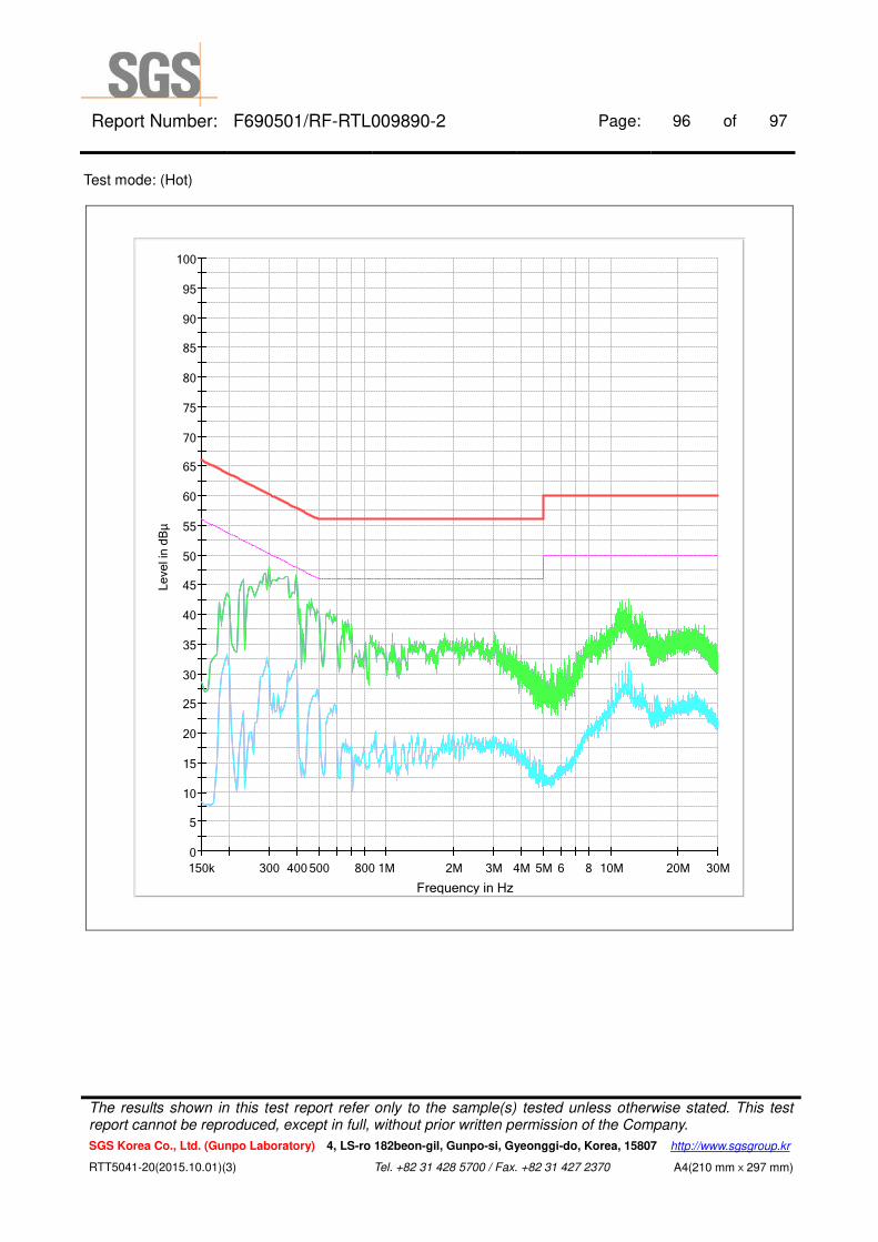
0.40 43.00 30.60 Hot 57.85 47.85 14.85 17.25
1.26 30.70 16.30 Hot 56.00 46.00 25.30 29.70
3.04 30.70 16.30 Hot 56.00 46.00 25.30 29.70
6.51 22.90 15.00 Hot 60.00 50.00 37.10 35.00
12.02 36.80 31.50 Hot 60.00 50.00 23.20 18.50
23.92 31.20 25.30 Hot 60.00 50.00 28.80 24.70
Remark;
1. Line ( H ): Hot, Line ( N ): Neutral
2. All channel of operation were investigated and the worst-case emissions were reported using
11a (Band 2A) / 6 Mbps / Low channel
3. Traces shown in plot mad using a peak detector and average detector
4. The limit for Class B device(s) from 150 ㎑ to 30 ㎒ are specified in Section of the Title 47 CFR.
5. Deviations to the Specifications: None.
The results shown in this test report refer only to the sample(s) tested unless otherwise stated. This test report cannot be reproduced, except in full, without prior written permission of the Company.
SGS Korea Co., Ltd. (Gunpo Laboratory) 4, LS-ro 182beon-gil, Gunpo-si, Gyeonggi-do, Korea, 15807 http://www.sgsgroup.kr
RTT5041-20(2015.10.01)(3) Tel. +82 31 428 5700 / Fax. +82 31 427 2370 A4(210 mmⅹ297 mm)

Report Number: F690501/RF-RTL009890-2 Page: 95 of 97
Test mode: (Neutral)
0
5
10
15
20
25
30
35
40
45
50
55
60
65
70
75
80
85
90
95
100
150k 300 400 500 800 1M 2M 3M 4M 5M 6 8 10M 20M 30M
Leve
l in
dBμ
Frequency in Hz
The results shown in this test report refer only to the sample(s) tested unless otherwise stated. This test report cannot be reproduced, except in full, without prior written permission of the Company.
SGS Korea Co., Ltd. (Gunpo Laboratory) 4, LS-ro 182beon-gil, Gunpo-si, Gyeonggi-do, Korea, 15807 http://www.sgsgroup.kr
RTT5041-20(2015.10.01)(3) Tel. +82 31 428 5700 / Fax. +82 31 427 2370 A4(210 mmⅹ297 mm)
Report Number: F690501/RF-RTL009890-2 Page: 96 of 97
Test mode: (Hot)
0
5
10
15
20
25
30
35
40
45
50
55
60
65
70
75
80
85
90
95
100
150k 300 400 500 800 1M 2M 3M 4M 5M 6 8 10M 20M 30M
Leve
l in
dBμ
Frequency in Hz
The results shown in this test report refer only to the sample(s) tested unless otherwise stated. This test report cannot be reproduced, except in full, without prior written permission of the Company.
SGS Korea Co., Ltd. (Gunpo Laboratory) 4, LS-ro 182beon-gil, Gunpo-si, Gyeonggi-do, Korea, 15807 http://www.sgsgroup.kr
RTT5041-20(2015.10.01)(3) Tel. +82 31 428 5700 / Fax. +82 31 427 2370 A4(210 mmⅹ297 mm)
Report Number: F690501/RF-RTL009890-2 Page: 97 of 97
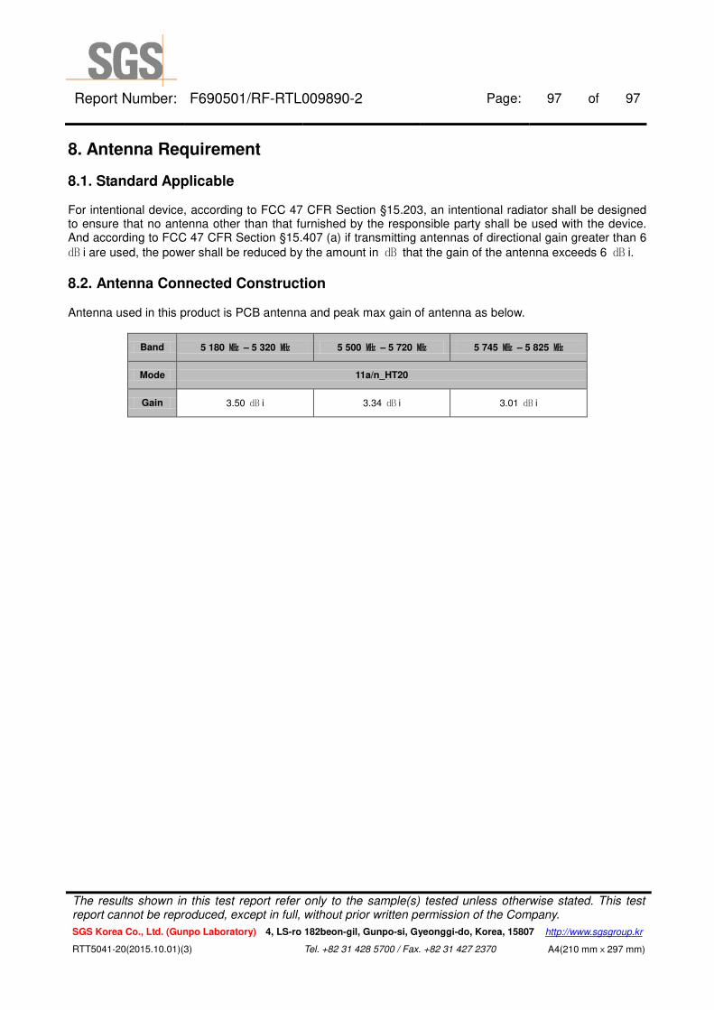
8. Antenna Requirement
8.1. Standard Applicable For intentional device, according to FCC 47 CFR Section §15.203, an intentional radiator shall be designed to ensure that no antenna other than that furnished by the responsible party shall be used with the device. And according to FCC 47 CFR Section §15.407 (a) if transmitting antennas of directional gain greater than 6
㏈ i are used, the power shall be reduced by the amount in ㏈ that the gain of the antenna exceeds 6 ㏈ i.
8.2. Antenna Connected Construction Antenna used in this product is PCB antenna and peak max gain of antenna as below.
Band 5 180 ㎒ – 5 320 ㎒ 5 500 ㎒ – 5 720 ㎒ 5 745 ㎒ – 5 825 ㎒
Mode 11a/n_HT20
Gain 3.50 ㏈ i 3.34 ㏈ i 3.01 ㏈ i
The results shown in this test report refer only to the sample(s) tested unless otherwise stated. This test report cannot be reproduced, except in full, without prior written permission of the Company.
SGS Korea Co., Ltd. (Gunpo Laboratory) 4, LS-ro 182beon-gil, Gunpo-si, Gyeonggi-do, Korea, 15807 http://www.sgsgroup.kr
RTT5041-20(2015.10.01)(3) Tel. +82 31 428 5700 / Fax. +82 31 427 2370 A4(210 mmⅹ297 mm)