Embed Size (px)
Citation preview

5
Close-Packed Structures
by
P. Krishna and D. Pandey
This electronic edition may be freely copied and redistributed for educational or research purposes
only.
It may not be sold for profit nor incorporated in any product sold for profit without the express pernfission of The Executive Secretary, International Union of Crystalk~graphy, 2 Abbey Square, Chester CIII 211U, UK
Copyr ight in this electronic ectition (i)2001 International [Jnion of Crys ta l lography
Published for the International Union of Crystallography
by University College Cardiff Press
Cardiff, Wales

© 1981 by the International Union of Crystallography. All rights reserved.
Published by the University College Cardiff Press for the International Union of Crystallography with the financial assistance of Unesco Contract No. SCfRP 250.271
This pamphlet is one of a series prepared by the Commission on Crystallographic Teaching of the International Union of Crystallography, under the General Editorship of Professor C. A. Taylor. Copies of this pamphlet and other pamphlets in the series may be ordered direct from the University College Cardiff Press, P.O. Box 78, Cardiff CF1 1XL, U.K.
ISBN 0 906449 08 1
Printed in Wales by University College, Cardiff.

Series Preface
The long te rm aim of the Commission on Crystallographic Teaching in establishing this pamphle t p rog ramme is to produce a large collection of short s ta tements each dealing with a specific topic at a specific level. The emphasis is on a particular teaching approach and there may well, in time, be pamphlets giving alternative teaching approaches to the same topic. I t is not the function of the Commission to decide on the 'best ' approach but to make all available so that teachers can make their own selection. Similarly, in due course, we hope that the same topics will be covered at more than one level.
The initial selection of ten pamphlets published together represents a sample of the various levels and approaches and it is hoped that it will st imulate many more people to contribute to this scheme. I t does not take very long to write a short pamphlet , but its value to someone teaching a topic fo r the first t ime c a n be very g rea t .
Each pamphle t is prefaced by a s ta tement of aims, level, necessary background, etc.
C. A. Taylor Edi tor f o r the Commission
The financial assistance of UNESCO, ICSU and of the International Union of Crystallog- raphy in publishing the pamphlets is gratefully acknowledged.

Teaching Aims
To help towards an understanding of the way in which close packed structures may be described and to begin to bridge the gap between the theoretical abstractions of basic crystallography and the world of real crystals.
Level
I t would be most appropriate in the later years of undergraduate courses, especially those in materials science. I t could also form an element in a postgraduate course of crystallography for newcomers to the subject.
Background A general familiarity with crystal lattices, crystal symmetry, the reg-
ional lattice and the basic principles of X-ray diffraction such as might be given in an introductory course is assumed.
Practical Resources
Crystal structure models are essential in understanding the material in • this article. An X-ray generator and rotation camera would be helpful.
Time Required for Teaching
It probably represents about 6 hours teaching if adequate use of models is to be made. Further t ime for X-ray photography of suitable single crystals of close packed structures would be an advantage.

C l o s e - P a c k e d Structures
P. Krishna and D. Pandey*
Depar tment of Physics, Banaras Hindu University, Varanasi, India
The crystal structures of a large number of metals, alloys and inorganic compounds can be described geometrically in terms of a close-packing of equal spheres, held together by interatomic forces. Frequently, the posi- tions of one kind of atoms or ions in inorganic structures correspond approximately to those of equal spheres in a close-packing with the other atoms distributed among the voids. All such structures will be referred to as close-packed structures though they may not be ideally close-packed. The close-packed arrangement of equal spheres in a plane is shown in Fig. 1 where each sphere is in contact with six other spheres. Since the symmetry of this layer i s 6mm, such a layer is called a hexagonal close-packed layer. Let this layer be called an A layer. It contains two types of triangular voids, one with the apex of the triangle upwards in the diagram and labelled B, and the other with the apex downwards and labelled C. In the two-dimensional unit cell indicated in the figure (a = b, , /= 120 °) the three positions A, B and C have coordinates 00, ½-~ and 21 gg -
In a three-dimensional packing the next hexagonal close-packed layer of spheres can occupy either the sites B or C, but not both. Similarly the layer above a B layer can be either C or A and that above a C layer either A or B. No two successive layers can be alike. The positions B and C are displaced with respect to A by vectors +S and - g respectively where S = a/3 ~1010} in the Miller-Bravais notation.
Any sequence of the letters, A, B and C with no two successive letters alike represents a possible manner of close-packing equal spheres. In such a three-dimensional close-packing, each sphere is surrounded by and touches 12 other spheres. This is the maximum number of spheres that can be arranged to touch a given sphere and it provides the maximum packing density for an infinite lattice arrangement. (There are however other arrangements of a f ini te number of equal spheres which have a higher packing density1.) It is evident from the foregoing that the number of different close-packed structures that are possible in three dimensions is infinite. The identity period or c dimension of the hexagonal unit cell in a three-dimensional close-packed structure is determined by the number of layers after which the stacking sequence repeats itself. The two most
* Now at the School of Materials Science and Technology, Banaxas Hindu University,
India. •

CAZA.LLL Fig. 1. The close-packing of spheres.
common close-packed structures which occur in nature are: (i) the hex- agonal close-packing (hcp)wi th a layer stacking A B A B . . and (ii) the cubic close-packing (ccp) with a layer stacking A B C A B C . . They have identity periods o f two and three layers respectively. In addition to the hcp and ccp modifications, a number of materials, like SiC, ZnS, CdI2, PbI2, AgI and GaSe-are known 2'3'4 to crystallize in a large variety of close-packed structures, called polytypes, with larger identity periods. The different polytype structures of the same material have identical a and b dimensions of their hexagonal unit cell but differ along c. Even for the same identity period of n layers, a number of different close-packed structures are possible with different arrangements of the n layers. The extent to which a real crystal structure approximates to a close-packing can be determined from the h/a ratio, where h is the separation between successive close-packed layers and a is the diameter of the spheres. For an ideally close-packed structure, this ratio must be ~/}= 0.81652'5. Table 1 lists the h/a ratio for some metals and inorganic materials with hcp structure.
Table i
Material h/ a Material h/ a
Cd 0.943 AgI 0.815 Zn 0.928 BeO 0.815 He 0.8165 CdSe 0.815 Co 0.814 ZnO 0.800 Mg 0.812 /kiN 0.800
• Sc 0.797 CdS 0.810

Voids in a Close-Packing
In case of close-packed inorganic compounds, the larger atoms or ions occupy positions approximately corresponding to those of equal spheres in a close-packing while the smaller atoms are distributed among the voids. Three-dimensional close-packings of spheres have two kinds of voids:
(i) If the triangular void in a close-packed layer has a sphere directly over it, there results a void with four spheres around it, as shown in Fig. 2a. Such a void is called a tetrahedral void since the four spheres surrounding it are arranged on the corners of a regular te t rahedron (Fig. 2b). If R denotes the radius of the four spheres surrounding a tetrahedral void, the radius of the sphere that would just fit into this void is given 2'5 by 0.225 R.
(ii) If a triangular void pointing up in one close-packed layer is covered by a triangular void pointing down in the adjacent layer, then a void surrounded by six spheres results (Fig. 2c). Such a void is called an octahedra! void since the six spheres surrounding it lie at the corners of a regular octahedron (Fig. 2d). The radius of the sphere that would just fit into an octahedral void in a close-pacl(ing is given 2'5 by 0.414 R.
Fig. 2(a)
Fig. 2 (c)
A
B
Figl 2 (b) A
A
A A
B
Fig. 2(d)
Fig. 2. Voids in a close-packing (a) Tetrahedral void, (b) Tetrahedron formed by the cenrres of spheres, (c) Octahedral void, (d) Octahedron formed by the centres
• of spheres.
A

To determine the number of tetrahedral a n d octahedral voids in a three-dimensional close-packing of spheres, we note that a sphere in a hexagonal close-packed layer A is surrounded by three B voids and three C voids (Fig. 1). When the next layer is placed on top of this, the three voids of one kind (say B) are occupied and the other three (say C) are not. Thus the three B voids become tetrahedral voids and the three C voids become octahedral voids. A single sphere in a three-dimensional close-packing will have similar voids on the lower side as well. In addition, the particular sphere being considered covers a triangular void in the layer above it and another in the layer below it. Thus two more tetrahedral voids surround the spheres. This results in 2 x 3 + 1+ 1 = 8 tetrahedral voids and 2 x 3 = 6 octahedral voids surrounding the sphere. Since a tetrahedral void is shared by four spheres, there are twice as many tetrahedral voids as there are spheres. Similarly, since an octahedral void is surrounded by six spheres, there are as many octahedral voids as there are spheres.
In an actual crystal structure a particular a tom can best fit into one or the other kind of void depending on its size relative to that of the close-packed atoms. Thus the radius ratio of the atoms present in a crystal imposes limitations on the coordination that they can have in real structures. Conversely, the coordination number of an a tom imposes a limitation on the radius ratio. In effect this means that the size and coordination number of a central a tom may require that its close-packed neighbours do not touch each other.
Symmetry and Space Group of Close-Packed Structures The symmetry of a single close-packed layer of spheres is 6mm. It has
2-, 3- and 6- fold axes of rotation normal to its plane as shown in Fig. 3. In addition it has three symmetry p lanes - -one perpendicular to the x-axis, one perpendicular to the y-axis and the third equally inclined to x and y. When two or more layers are stacked over each other in a close-packing the resulting structure retains all the three symmetry planes and has at least 3-fold axes parallel to [00.1] through the points 000, ½ ~ 0 and 21 ~ 0 as shown in Fig. 4. Such a structure belongs to the trigonal system and has a space group P 3 m l or R 3 m l , according as the lattice is hexagonal or rhombohedral . This represents the lowest symmetry of a close-packing of spheres comprised of a completely arbitrary periodic stacking sequence of close-packed layers. If the arbitrariness in stacking successive layers in the unit cell is limited then higher symmetries can also result. It can be shown 2'6 that it is possible to have three additional symmetry elements, namely, a centre of symmetry (i), a mirror plane perpendicular to [00.1], and a screw axis 63. It was shown by Belov 7 that
4
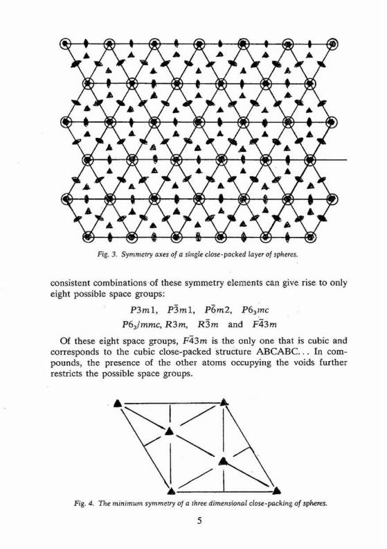
Fig. 3. Symmetry axes of a single close-packed layer of spheres.
consistent combinations .of these symmetry elements can give rise to only eight possible space groups:
P 3 m l , P3ml, P6m2, P63mc
P63/mmc, R3m, R3m and F43m
Of these eight space groups, FF~3m is the only one that is cubic and corresponds to the cubic close-packed structure A B C A B C . . . In com- pounds, the presence of t h e other atoms occupying the voids further restricts the possible space groups.
Fig. 4. The minimum symmetry o~" a three dimensional close-packing of spheres.
5

Possible Lattice Types
Close-packings of equal spheres can belong to the trigonal, hexagonal or cubic crystal systems. When the structure has the minimum symmetry discussed earlier it belongs to the trigonal system. When it has a 63 axis of symmetry it belongs to the hexagonal system. Structures belonging to the hexagonal system necessarily have a hexagonal lattice, i.e. a lattice in which we can choose a primitive unit cell with a = b:~ c, a =/3 = 9 0 °, 3' = 120 °. The primitive unit cell of the hcp structure is shown in Fig. 5. It should be noted that there are two spheres associated with each lattice point in the hop structure, one at 000 and the other at ½2½. Structures belonging to the trigonal system can have either a hexagonal or a rhombohedra l lattice. By a rhombohedra l lattice is meant a lattice in which we can choose a primitive unit cell with a = b = c, o~ =/3 = 3,7 ~ 90 °. Both types of lattices can be referred to either hexagonal or rhom- bohedral axes, the unit cell being non-primitive when a hexagonal lattice is referred to rhombohedra l axes or vice versa. Figure 6 shows a rhom- bohedral lattice in which the primitive cell is defined by the rhombohedra l axes al , a2, a3; but a non-primitive hexagonal unit call can be chosen by adopting the axes A1, A2, C. T h e latter has lattice points at 0 0 ~ 2½½ and
22. In the special case of the close-packing A B C A B C . . . . (with'the ideal h/a ratio of 0.8165) the primitive rhombohedra l lattice has o~ =/3 =3 ' = 60 °, which enhances the symmetry to FFt3m and enables the choice of a face-centred cubic unit cell. The relationship between the fcc and the primitive rhombohedra l unit cell is shown in Fig. 7. The three-fold axis of the rhombohedra l unit cell coincides with one of the (111) directions of
/ Fig. 5. The primitive unit cell of the hcp structure.
y

/
/
/
/ \z
/ t "
T..A ! Fig. 6. A rhombohedral lattice (al, a2, aa) referred to hexagonal axes (A 1, A 2, C)
(After M. J. Buerger, X - ray crystallography, Wiley : New York 1953).
the cubic unit cell. The close-packed layers are thus parallel to the {111} planes in the cubic close-packing.
In close-packed structures, it is generally convenient to refer both hexagonal and rhombohedral lattices to hexagonal axes. The projection of the hexagonal lattice on the (001) plane is shown in Fig. 8. The axes, x, y define the smallest hexagonal unit cell, the z axis being normal to the plane of the paper; the hexagonal unit cell is primitive with all the lattice points at 000. Figure 9 depicts the projection of a rhombohedral lattice on the (00.1) plane. The full lines Oxh, Oyh represent the hexagonal axes
Fig. 7. The relationship between the fcc and the primitive rhombohedral unit cell of the cop structure.
7

• {P e +y.~ • f " 0
/ i I -~ ~ +y_,
t t • t B " 0 I I i " I I ~ . , . / i l
i "/+', , / j , / " ~ I +x3
+x~ ~ ~" / ~ +Y~
9 ' + X z • • • • •
~g. 8. The proiection o.f the hexagonal laniee on the (O001)-plane. Shows different ways of choosing hexagonal axes (after International Tables for Crystallog-
raphy, Kynoch Press: Birmingham, 1952).
0 0 O 0 O e
2/3 e 2 ~ 2/3 •
0 • 1"~ / / ~'~ +Yh 0
213 2 2/3 0
I/3 . / ~ I Y / 1 / 3 / 1 /3 .
o07/ ~ '0 0 •
2/3 • ~ • 2/3 • 2/3
+Xh- 01/3 • 1/3 1/3 Fig. 9. Projection of a rhombohedral lattice (obverse setting). Shows the choice o[ hexagonal (---~) and rhombohedral ( - - - - ) axes (after International Tables for
Crystallography Vol. I, Kynoch Press: Birmingham, 1952).
8

and the three dotted lines represent rhombohedra l axes. It is evident from the figure that the hexagonal unit cell of a rhombohedra l lattice is non-primitive with lattice points at 000, 211 1 2 2 ~ and ~ 3 . If the lattice is rotated through 60 ° around [001], the hexagonal unit cell will then be
1 2 1 2 1 2 centred at ~ and ~ . These two settings of the rhombohedra l lattice are called 'obverse ' and ' reverse ' settings. They are indistinguishable by X-ray methods since the two are crystallographically equivalent: they represent twin arrangements when both of them occur in the same single crystal.
N o t a t i o n s U s e d for R e p r e s e n t i n g C l o s e - P a c k e d Structures
The special notations employed to distinguish the different close- packed structures of a material have been described in detail by Verma and Krishna 2. In this section a brief description of only those notations which are more commonly used is given.
(a) Ramsdell's notation s
Close-packed structures can be designated by specifying the total number of layers in the hexagonal unit cell followed by the letter H, R or C to indicate the lattice type. Thus a symbol nH represents a structure with n layers in the primitive hexagonal unit cell while mR denotes a structure whose primitive lattice is rhombohedra l and contains m layers in its hexagonal unit cell. In order to distinguish structures with same lattice type as well as the same repeat period along c, subscripts a, b, c or 1, 2, 3 are often used. This notation is applicable to all close-packed structures but it does not reveal the actual ar rangement of the layers in the unit cell.
(b) The classical ABC notation
As pointed out earlier, the actual a r rangement of layers in all close- packed structures can be described in terms of the A B C notation for close-packing of spheres. Thus the SiC type 6 H has six Si and six C layers in its hexagonal unit cell stacked as A a B/3 CT A a CT B/3 where the Roman letters denote positions of layers of Si atoms and the Greek letters those of C atoms. Since the positions of C atoms are fixed relative to the positions of Si atoms it is customary to omit the Greek letters and write the structure as A B C A C B . In the case of CdI2 structures, where the Cd atoms lie in the octahedral voids between alternate close-packed iodine layers, one often retains the Greek letters to denote the positions of Cd layers. Thus CdI 2 type 4 H has a structure A v B C a B . While this notation gives a complete description of the structure it does not reveal the symmetry or lattice type directly and becomes cumbersome for structures with large repeat periods.

(c) Zhdanov notation
If the layers in a close-packed structure are projected on to one of the close-packed planes, the atoms fall into one of the three possible posi- tions A, B and C with xy coordinates 00, ½~ and 21 ~ respectively. The passage f rom A---~B---~C--*A involves a vector translation of 12 ~g in the basal plane, whereas the passage f rom A--~C---~B---~A involves a vector translation of ~, ½ = -~ , - ~ (Fig. 1). H~igg 9 therefore denoted the former by a plus sign (+ ) and the latter by a minus sign ( - ) . A structure such as /kBCB is thus represented as + + - - . The relationship between the three orientations, A, B and C of the close-packed layers may also be visualized in terms of clockwise or anticlockwise rotation about [00.1] through 60 °. Frank 1° used the symbols /k and V for the two rotations. Thus the /~ symbol implies a cyclic change A---~B--~C--~A and the symbol V implies an anticyclic change. No compactness results f rom the use of these + a n d - or /k and V symbols for representing a close-packed structure because their number remains the same as the number of layers in the A B C sequence of the structure. Zhdanov 11 therefore suggested summing up the consecutive + (or A) and - (or V) signs and putting them down in numeral figures. Thus the 6 H SiC structure having the A B C sequence A B C A C B and a H~igg sequence + + + - - - is denoted by the symbol (33) in the Zhdanov notation.
Ramsdell 8 interpreted the Zhdanov symbols in terms of the zig-zag sequence of Si and C atoms in the (1120) planes of SiC structure. These planes contain all the atoms of the structure since the three symmetry axes parallel to [001] all lie in this plane. Figure 10 illustrates the meaning of the zig-zag sequence, taking the 6 H (33) structure of SiC as example. If a Si or C atom lies on A in one layer, the next must be either to the right on B, or to the left on C. If to the right, the third layer may have its a tom continue to the right or it may change direction and go to the left. Because of these repeated changes, a zig-zag pattern results. Such an arrangement can be described in terms of the number of layers added in each direction in succession and has been called the 'zigzag sequence' by Ramsdell . The unit cell is completed after arriving at an identical a tom having the same environment as the a tom f rom which one started. Thus in Fig. 10 the unit-cell of 6 H is completed at 2 and not at 1. The Zhdanov notation is by far the most convenient and concise notation to describe close-packed structures.
(d) The h-c notation
In the h-c notation, used by Pauling ~2, Wyckoff 13 and Jagodzinski 14, one specifies each layer in terms of the orientation of layers above and below it. A layer is said to be in hexagonal configuration and is denoted
10

"v
"r ~z
r.) i '
Z
A ~ B C A ~ B C A ~ B
Fig. I0. Ramsdell's Zig-Zag sequence of Si (or C) atoms in the (112.0) plane of 6 H (ABCACB).
as 'h' if it is surrounded on either side by layers in similar orientations. A layer is said to be in cubic configuration and is denoted as 'c' if it is surrounded on either side by layers in different orientations. Thus the 6 H SiC structure with stacking sequence A B C A C B can be written as hcchcc in the h-c notation. This notation is specially usefu'[ in dealing with X-ray diffraction effects from faulted structures and for calculating stacking fault energies ~5. ,
It is quite easy to transform from one notation to anotlaer. For this it is convenient to write first the complete A B C sequence.of the structure and then express this in the desired notation. Some close-packed structures expressed in different notations are listed in Table 2. ~ "
Table 2. Different notations for describing some close- packings
Ramsdell ABC Zhdanov h-c notation sequence number notation
2/-/ AB (Ii) h 3C ABC co c 4 H ABCB (22) hc 6 H 1 ABCACB (33) hcc 6H 2 ABCBAB (2211) hchchh 9R ABACACBCB (12) hhc
11

Examples of Some Close-Packed Structures
(i) Elements The structure of many of the metallic and non-metall ic elements can be
described in terms of a close packing of equal spheres. There is a clear relationship between the structure and the position of an element in the Periodic Table. Elements in the same group tend to have the same structure at room temperature ; for example, the alkali metals and Be, Mg, Zn and Cd ~ r o u p I I A and IIB) are hcp; Cu, Ag and Au (group IB) are ccp. The elements of the rare-ear th series crystallize in the ccp structure, the hcp structure or the 4 H (ABCB) structure (e.g. Sm). The stable modification of Co at room tempera ture is probably hcp but it undergoes t ransformation to a ccp structure at high temperature .
(ii) Inorganic compounds (a) Silicon carbide and zinc sulphide
SiC has a binary tetrahedral structure in which the Si and C layers are stacked alternately, each carbon layer occupying half the tetrahedral voids between successive close-packed silicon layers. One can regard the structure as consisting of two identical interpenetrating close-packings, one of Si and the other of C, with the one displaced relative to the other along the e-axis through one fourth of the layer spacing. The binding between Si and C atoms in SiC is predominant ly covalent. The silicon- carbon bond length of 1.94.& as calculated f rom the known covalent tetrahedral radii of C and Si is nearly equal to the observed silicon- carbon bond l en~h of 1.89 A. The tetrahedral ar rangement of Si and C in SiC does not permit either a centre of symmetry (i) or a plane of symmetry (m) perpendicular to [00.1]. Silicon carbide can therefore have only four possible space g r o u p s - P 3 m l , R 3 m l , P63mc and F43m.
Commercia l SiC crystals are grown at temperatures above 2000°C and are called a-SiC crystals. The more common modifications in the a -S iC crystals are 6H, 15R and 4H. They have stacking s e q u e n c e s / A B C A C B / ( = 6H), / A B C B A C A B A C B C A C B / ( = 15R) a n d / A B C B / . . . (4/-/). Fig- ure 11 depicts the structure of the most common a-SiC modification 6 H with a packing A B C A C B . In addition to the common modifications (often called the 'basic structures ' of a-SiC) several polytype structures with stacking sequences of larger repeat periods have been discovered. These have either a hexagonal or a rhombohedra l lattice 2. Table 3 lists the known structures of SiC. In all these structures the h/a ratio is 0.817, which is very close to the value of 0.8165 for an ideal close-packing. The cubic or /3-SIC, with a packing / A B C / A B C / . . . , is denoted as 3 C and normally forms 2 at temperatures below 1800°C. It is regarded as the
12

Fig. 11. Tetrahedral arrangement of Si and C atoms in 6 H SiC structure.
low-tempera ture modification of SiC and undergoes a solid-state transfor- mation to the 6 H structure at tempera tures above 1800°C 2'16'17. The wurtzite (2/-/) modification of SiC, with a stacking s e q u e n c e / A B / A B / . . . . does not occur in commercial SiC and has been synthesized by special methods between the temperatures of 1400 and 1500°C 18. I t is regarded as a metastable modification of SiC and undergoes solid-state t ransforma- tion to the 3 C and 6 H structures at tempera tures above 1400°C 17. The h/a ratio in this structure is 0.8205 which differs considerably from t h e ideal h/a ratio for perfect close-packing.
13

Table 3. List of SiC polytypes with known structures
Structure Structure Polytype (Zhdanov sequence) Polytype (Zhdanov sequence)
2H 11 54H (33)6323334 3 C ~o 57H (23)93333 4 H 22 57R (33),_34 6 H 33 69R 1 (33)332 8H 44 69R 2 33322334 10H 3322 75R l (33)334 14H (22)233 75R 2 (32)3(23) 2 15R 23 81H (33)535(33)634 16H 1 (33)z22 • 84R (33)3(32)2 16H 2 332332 87R (33)432 18H (22)333 90R (23)43322 19H (23)322 96R (33)33434 20H (22)344 99R (33)43222 21H 333534 105R (33)532 21R 34 111R (33)534 24R 35 120R (22)523222333 27H (33)2(23) 3 123R (33)632 27R 2223 141R (33)732 33R 3332 147R (3332)432 33H 1 (33)2353334 159R (33)s32 33H-2 (33)3(23) 3 168R (23)1o33 36H I (33),_32(33)234 174R (33)66(33)54 3 6 H , (33)43234 189R (34)843 39H (33),_32(33)3(32) 2 222R (33)634(33)~34 39R 3334 267R (23)1722 45R 232332 273R (23)1733 51R 1 (33),_32 303R (33)1632 51R 2 (22)323 393R (33)2132
The structure of ZnS is analogous to that of SiC. The bonding in ZnS is known to be partly ionic and partly covalent. The wurtzite and sphalerite modifications of this compound, which occur as minerals, correspond to the / A B / A B / A B / . . . and / A B C / A B C / . . . . packings respectively.
The cubic form is known to be the low-temperature modification and undergoes a reversible phase transformation 2 to the 2 H form around 1020°C. In addition to these two c o m m o n modifications, ZnS is known 19 to display a large variety of polytype structures with larger identity periods. As stated earlier, all the polytype modifications of a material have identical a and b lattice parameters and differ only along c. The h/a ratio for the 2 H modification of ZnS is 0 .818 which is somewhat different from the ideal value 0 .8165 for a perfect close-packing.
14

Cadmium Iodide
Cadmium iodide is an ionic compound, the ionic radii of Cd and I being 0 .97 /~ and 2.16 ~ respectively 2. The structure consists of a close-packing of the I ions with the Cd ions distributed among the octahedral voids. The radius ratio tea~h= 0.45 permits the Cd ions to occupy the octahedral voids. Since there are only half as many Cd ions as I ions in the structure, only half of the total octahedral voids are occupied. Thus the Cd and I layers are not stacked alternately; there is one Cd layer after every two I layers as shown in Fig. 12. The structure therefore consists of molecular sheets (called minimal sandwiches) with a layer of Cd ions sandwiched between two close-packed layers of I ions. The binding within the minimal sandwich is ionic in character and is much stronger than the binding between successive sandwiches which is of van der Waals type. It is because of the weak van der Waals bonding between the successive
'--4 I i ,-',. ', . " L ,.":: "v--. 1 "I • I ~ % I = | I
Fig. 12. The layer structure of Cdl2: small circles represent Cd ions and larger ones the I ions (after A. F. Wells, Structural fnorganic Chem/stry, Clarendon Press:
Oxford, 1945).
15

minimal sandwiches that the material possesses the easy cleavage charac- teristic of a layer structure. Cadmium iodide structures can have a centre of symmetry in octahedral voids, but cannot have a symmetry plane perpendicular to [00.1]. Cadmium iodide can therefore have five possible space groups - P3ml, P3rn, R3m, R3rn and P63mc. Cubic symmetry is not possible in CdI2 on account of the presence of Cd atoms. The most common modifications of CdI2 are 4 H and 2 H with stacking sequences / A y B C a B / . . . . . and / A y B / A T B / . . . . respect ively , where the Greek letters denote the positions of Cd ions. In addition, this material also displays 2"19 a number of polytype modifications of large repeat periods. From the structure of CdI2 it follows that the identity period of all such modifications must consist of an even number of iodine layers. The h/a ratio in all these modifications of CdIe is 0.805 which differs considerably from the ideal value of 0.8165.
Identification of Close-Packed Structures by X-ray Diffraction
When a material crystallizes into a number of different close-packed structures all of which have identical layer spacings and different only in the manner of stacking the layers, crystals of the different modifications look alike and cannot be identified by their external morphology. In order to identify such polytype modifications, it is necessary to determine the number of layers .in the hexagonal unit cell and the lattice type of the crystal. This can be conveniently achieved by recording reciprocal-lattice rows parallel to c* on single-crystal X-ray diffraction photographs. Since the different polytypes of the same material have identical a and b parameters of the direct lattice, the a'b* reciprocal lattice net is also the same. The reciprocal lattice of these modifications differ only along the c* axis which is perpendicular to the layers. For each reciprocal-lattice row parallel to c "~ there are others with the same value of the cylindrical coordinate ~. For example, the rows 10./, 01.l, i l . l , 10.I, 01.1 and l l . l all have f = [a*l. Due to symmetry, it is sufficient to record any one of them on X-ray diffraction photographs. The number of layers, n, in the hexagonal unit cell can be found by determining the c parameter from c-axis rotation or oscillation photographs and dividing this by the known layer-spacing h for that compound (n = c/h). The density of reciprocal points along rows parallel to c* depends on the periodicity along the c axis. The larger the identity period along c, the more closely spaced are the reciprocal-lattice points along c*. In case of long-period polytypes the number of layers in the hexagonal unit cell can be determined by using a simple alternative method suggested by Krishna and Verma 2°. This requires the counting of the number of spacings after which the sequence
16

o
• ° ;I
- i
" . j
"1
• o . _. • .
o
.. ---.-~ ..--
o " . " " . . i o , e . . ° )
. o
l ib
Q
Q
Q
Q
Q
b-ig. 13. 77~e 10.l rows of some close-packed structures of SiC as recorded on c - axis oscillation photographs (a) 6 H (b) 3 6 H (c) 90R (d) D/s. 2H.
17

of relative intensities begins to repeat along the 10./ row of spots on an oscillation or Weissenberg photograph. If the structure contains one- dimensional disorder due to a random-distr ibut ion of stacking faults, this effectively causes the c lattice pa ramete r to become infinite (c*--~O) and results in the production of characteristic streaks along reciprocal lattice rows parallel to c*. I t is therefore difficult to distinguish by X-ray diffraction between structures of very large unresolvable periodicities and those with random disorder. Latt ice resolution in the electron-microscope has been used in recent years to identify such structures 21. Figure 13 depicts the 10 . / rows of some close-packed structures of SiC as recorded on c-axis oscillation photographs. When the structure has a hexagonal lattice, the positions of spots are symmetrical about the zero layer line on the c-axis oscillation photograph as seen in Fig. 13 (a) and (b) for the 6 H and 3 6 H SiC structures. However , the intensities of the reflections on the two sides of the zero layer line are the same for the 6 H structure but not for the 36/-/. This is because the 6 H structure belongs to the hexagonal space group P63mc whereas the 3 6 H structure belongs to the trigonal space group P3 rn 12. The apparent mirror symmetry perpendicular to the c-axis in Fig. 13 (a) results f rom the combination of the 63 screw axis with the centre of symmetry introduced by X-ray diffraction 22. For a structure with a rhombohedra l lattice, the positions of X-ray diffraction spots are not symmetrical about the zero layer line because the hexagonal unit cell is non-primitive causing the reflections hkl to be absent when - h + k + 17~3n (+n = 0 , 1, 2 , . . . ) . For the 10./ row this means that the permit ted reflections above the zero layer line are 10.1, 10.4, 10.7 etc. and below the zero-layer line 10.2, 10.5, 10.8 etc. The zero layer line will therefore divide the distance between the nearest spots on either side (namely 10.1 and 10.7.) approximately in the ratio 1 : 2. This enables a quick identifica- tion of a rhombohedra l lattice. Thus the lattice type corresponding to Fig. 13 (c) is rhombohedra l and the polytype is designated as 90R and belongs to the space group R3m. Figure 13(d) depicts the 10 . / r ow of a disordered 2 H SiC structure. The diffuse streak connecting the strong 2 H reflections is due to the presence of a r andom distribution of stacking faults in the 2 H structure.
C o n c l u s i o n
Several other materials with close-packed structures are now known to exhibit similar complicated close-packings and it is necessary to point out to students that the hcp and ccp structures are not the only close-packed structures which occur in nature. The mechanism of the formation of long-period polytype structures, with a periodicity much larger than the range of any known atomic forces, has posed a problem in solid-state
18

physics which has yet to be answered satisfactorily. For a detailed account of polytype structures observed in different materials and the different theories put forward to explain their formation, the reader is referred to a book by Verma and Krishna 3 and to more recent review articles 23'24'25'26.
R e f e r e n c e s
1. A. H. Boerdijk, Philips Res. Rept. 7 (1952) 303. 2. A. R. Verma and P. Krishna, Polymorphism and Polytypism in Crystals, Wiley, New
York (1966). Russian translation, edited by A. S. Povaxennykh, MIR: Moscow (1969). 3. P. R. Prager, Acta Cryst. A30 (1974) 369. 4. J. C. J. M. Terhell and W. C. Van der Vleuten, Mater. Res. Bull. 11 (1976) 101. 5. L. V. Azaroff, Introduction to Solids, McGraw-Hill (1960). 6. International Tables for X-ray crystallography Vol. III, Kynoch Press, Birmingham
(1962). 7. N. V. Belov, The Structure of Ionic Crystals and Metal Phases (in Russian) Izd. AN
SSSR: Moscow (1947). 8. L. S. Ramsdell, Am. Mineralogist 32 (1947) 64. 9. G.I-IS.gg, Ark. Kern. Mineral. Geol. 163 (1943) 1.
10. F. C. Frank, Phil. Mag. 42 (1951) 1014. 11. G. S. Zhdanov, Compt. Rend. Acad. Sci. URSS 48 (1945) 43. 12. L. Pauling, Nature of the Chemical Bond, Cornell Univ. Press: Ithaca (1945). 13. R. W. G. Wyckoff, Crystal Structures, Vol. I, Interscience: New York (1948). 14. H. Jagodzinski, Acta Cryst. 2 (1949) 201. 15. D. Pandey and P. Krishna, Mater. Sci. Eng. 20 (1975) 243; ibid. 26 (1976) 53. 16. H. Jagodzinski, Kristallografiya, 16 (1971) 1235. 17. P. Krishna and R. C. Marshall, J. Crystal Growth, 9 (1971) 319; ibid 11 (1971) 147. 18. R. F. Adamsky and K. M. Merz, Z. Krist. 111 (1959) 350. 19. G. C. Trigunayat and G. K. Chadha, Phys. Star. Sol. (a) 4 (1971) 1. 20. P. Krishna and A. R. Verma, Proc. Roy. Soc. (London), Ser A272, (1963) 490. 21. M. Dubey, G. Singh and G. Van Tendeloo, Acta Cryst. A33 (1977) 276. 22. L. S. Ramsdell and J. A. Kohn, Acta Cryst. 4 (1951) 111. 23. P. Krishna and A. R. Verma, Physica Stat. Sol. 17 (1966) 437. 24. P. T. B. Shaffer, Acta Cryst. B25 (1969) 477. 25. G. C. Trigunayat and A. R. Verma, in Crystallography and Crystal Chemistry of
Materials with Layered Structures, D. Reidel Pub. Co.: Dordrecht-HoUand (1976) p. 269. 26. P. Krishna and D. Pandey, in Aduances in Crystallography Oxford and IBH :New Delhi
(1978).
19

International Union of Crystallography Commission on
Crystallographic Teaching
List of booklets in the first series
1 A non-mathematical introduction to X-ray diffraction
by C.A. Taylor 2
An introduction to the scope, potential and applications of X-ray analysis by M. Laing
3 Introduction to the Calculation of Structure Factors
by S.C. Wallwork 4
The Reciprocal Lattice by A. Authier
5 Close-packed structures
by P. Krishna and D. Pandey 6
Pourquoi les groupes de Symetrie en Cristallographie by D. Weigel
7 Solving the phase problem when heavy atoms are in special positions
by L. Hohne and L. Kutchabsky 8
Anomolous Dispersion of X-rays in Crystallography by S. Caticha-Ellis
9 Rotation Matrices and Translation Vectors in Crystallography
by S. Hovm611er 10
Metric Tensor and Symmetry operations in Crystallography by G. Rigault
Price 95p each Available from
University College Cardiff Press, P.O. Box 78
Cardiff CF1 1XL United Kingdom
Cheques should be made payable to University College Cardiff


![CHAPTER 3: CRYSTAL STRUCTURES & PROPERTIESamoukasi/CBE30361/Lecture_Density_Addition.pdf · • Rare due to poor packing (only Po [84] has this structure) • Close-packed directions](https://img.pdfslide.us/doc/110x75/5f151e4fe5e85f2a811d702c/chapter-3-crystal-structures-amoukasicbe30361lecturedensityadditionpdf.jpg)


![253.pptx [Last saved by user] - University of Babylon · HEXAGONAL CLOSE-PACKED STRUCTURE An HCP crystal is a closeAn HCP crystal is a close-packed structure with the stacking sequence](https://img.pdfslide.us/doc/110x75/5af2e01f7f8b9aa91690f0d3/253pptx-last-saved-by-user-university-of-close-packed-structure-an-hcp-crystal.jpg)