Embed Size (px)
Citation preview
PVGTR - Braking Tests
Page - 1
PVGTR2004-18 (test-wip e) 5. BRAKING TESTS AND THE REQUIRED PERFORMANCE OF BRAKING SYSTEMS. 5.1. GENERAL REQUIREMENTS 5.1.1. The performance prescribed for braking systems is based on the stopping distance and the
mean fully developed deceleration. The performance of a braking system shall be determined by measuring the stopping distance in relation to the initial speed of the vehicle and by measuring the mean fully developed deceleration during the test.
5.1.2. The stopping distance shall be the distance covered by the vehicle from the moment when
the driver begins to activate the control of the braking system until the moment when the vehicle stops; the initial speed shall be the speed at the moment when the driver begins to activate the control of the braking system; the initial speed shall not be less than 98% of the prescribed speed for the test in question.
The mean fully developed deceleration ( dm ) shall be calculated as the deceleration
averaged with respect to distance over the interval vb to ve , according to the following formula:
s / m )S - S( 25.92
v - v = d MFDD 2
be
e2
b2
m
where: vo = initial vehicle speed in km/h, vb = vehicle speed at 0.8 vo in km/h, ve = vehicle speed at 0.1 vo in km/h, Sb = distance travelled between vo and vb in metres, Se = distance travelled between vo and ve in metres. The speed and distance shall be determined using instrumentation having an accuracy of
± 1% at the prescribed speed for the test. The dm may be determined by other methods than the measurement of speed and distance; in this case, the accuracy of the dm shall be within ± 3%.
5.1.3. General Test Conditions: For the approval or assessment of any vehicle, the braking performance shall be measured
during road tests conducted following these rules: 5.1.3.1. the vehicle's condition as regards mass must be as prescribed for each type of test and be
specified in the test report; 5.1.3.2. the test must be carried out at the speeds prescribed for each type of test; if the maximum
design speed of a vehicle is lower than the speed prescribed for a test, the test shall be performed at a speed that is set at a multiple of 5 km/h that is 4 to 8 km/h less the vehicle's maximum speed. The stopping distance achieved shall be no greater than specified by the formula given for the particular requirement.
5.1.3.3. during the tests, the force applied to the brake control in order to obtain the prescribed
performance must not exceed the maximum force laid down; 5.1.3.4. the road must be dry and have a surface affording an adhesion coefficient (PFC) in the
range 0.8 - 0.9, unless specified otherwise in the relevant stages of the test sequence; 1.3.5. the tests must be performed when there is no wind liable to affect the results;

Annex 1 PVGTR - Braking.
Page - 2
5.1.3.6. Temperatures at the start of the tests. Ambient. The ambient temperature shall be lie between 0 and 45
oC.
Tyres. These must be cold and at the pressure prescribed for the load actually borne by the
wheels when the vehicle is stationary Brakes. The average initial brake temperature (IBT) of the wheel brakes on the hottest
axle must be between 65 and 100oC. Temperatures may be measured as outlined in ISO
PAS 12158. 5.1.3.7. The prescribed performance must be obtained without locking of the wheels at speeds
exceeding 15 km/h, without deviation of the vehicle, from a 3.5 m wide lane, without exceeding a yaw angle of 15o, and without abnormal vibrations;
5.1.3.8. For vehicles powered completely or partially by an electric motor (or
motors), permanently connected to the wheels, all tests must be carried
out with these motor(s) connected.
5.1.3.9. for vehicles as described in paragraph 5.1.3.8., fitted with an electric regenerative braking
system of category A, behaviour tests defined in paragraph 1.4.3. of this Annex shall be carried out on a track with low adhesion, peak friction coefficient (PFC) of 0.3 or less ;
5.1.3.9.1. moreover, for vehicles fitted with an electric regenerative braking system of category
A, transient conditions such as gear changes or accelerator control release, must not affect the behaviour of the vehicle in these low adhesion conditions.
5.1.3.10. in tests required by paragraphs 5.1.3.9. and 5.1.3.9.1. wheel locking is not allowed. However steering correction is permitted if the angular rotation of the steering control is
within 120° during the initial 2 seconds and not more than 240° in all. In other tests, smaller levels of <90
o will be allowed.
5.1.3.11. For a vehicle with electrically actuated service brakes powered from traction batteries (or an auxiliary battery) which receive(s) energy only from an independent external charging system, these batteries shall, during braking performance testing, be at an average of not more than 5% above that (low) state of charge at which the brake failure warning prescribed in paragraph 4.3.19.1.1. is required to be given.
If this warning is given, the batteries may receive some recharge during the tests, to keep them in the required state-of-charge range.
5.1.4. Behaviour of the vehicle during braking 5.1.4.1. In braking tests, and in particular in those at high speed, minor steering correction is
allowed but the general behaviour of the vehicle during braking must be checked. 5.1.4.2. Behaviour of the vehicle when braking on a road on with reduced adhesion must meet
the relevant Braking Distribution or ABS requirements
5.1.4.3. In the case of a Regenerative Braking System of Category B, where the braking for a particular axle (or axles) is comprised of more than one source of braking torque, and any individual source can be varied with respect to the other(s), the vehicle shall satisfy the Braking Distribution or ABS requirements of under all relationships permitted by its control strategy and this may be tested.

PVGTR - Braking Tests
Page - 3
5.2. ROAD TEST PROCEDURES. These shall follow the sequence of tests as specified in Table 1 below
Table 1.--Road Test Sequence _________________________________________________________ Section/Paragraph Testing order No. _________________________________________________________ Vehicle laden (to GVWR): 1 Burnish...............................................………. 5.2.1. 2 Wheel lock sequence...................................... 5.2.4. Vehicle unladen (at LLVW): 3 Wheel lock sequence...................................... 5.2.4. 4 ABS performance.......................................…. 5.2.6. 5 Torque wheel..........................................……. 5.2.5. Vehicle laden (to GVWR): 6 Torque wheel...........................................…… 5.2.5. 7 Cold effectiveness.....................................….. 5.2.7. 8 High speed effectiveness................................. 5.2.8. 9 ABS performance ………………………….. 5.2.6. 10 Stops with engine off.................................….. 5.2.9. Vehicle unladen (at LLVW): 11 Cold effectiveness....................................…. 5.2.7. 12 High speed effectiveness................................ 5.2.9. 13 Failed ABS ......................................……. 5.2.10. 14 Failed proportioning valve............................ 5.2.11. 15 Hydraulic circuit failure............................… 5.2.12. Vehicle laden (to GVWR): 16 Hydraulic circuit failure.............................… 5.2.12. 17 Failed ABS .......................................…… 5.2.10. 18 Failed proportioning valve.............................. 5.2.11. 19 Power brake unit failure..............................… 5.2.13. 20 Parking brake.........................................…… 5.2.14. 21 Type 1 test - Heating Snubs............................ 5.2.15.1. 22 Hot Performance.......................................….. 5.2.15.2. 23 Brake cooling.........................................……. 5.2.15.3. 24 Recovery Performance.................................... 5.2.15.4. 25 Recovery performance for vehicles with RBSB 5.2.15.4.4.
26 Hot performance for vehicles with RBSB ….. 5.2.15.5.

Annex 1 PVGTR - Braking.
Page - 4
5.2.1. Preparation of Brake Linings. If tests are to be made on a new production vehicle, the burnish sequence below shall be
undertaken before brake performance tests are commenced. If testing a manufacturer submitted vehicle which, by bedding and conditioning the linings
in a similar manner to the procedure explained below, has been made ready for brake performance testing, the following procedure may be omitted.
General information. The burnish procedure is a series of stops which also provides the opportunity for vehicle
familiarization and final adjustment and checking of the instrumentation. There is no end requirement to this initialization procedure other than brake readiness. 5.2.1.1. Vehicle conditions. a) Vehicle laden. b) In the normal gear for the test speed. c) Conducted on a normal dry asphalt road surface or equivalent. 5.2.1.2. Test conditions and procedure. a) IBT: No greater than 100oC at the commencement of each stop. b) Test speed 80 km/h. c) Braking rate: Maintain a constant 3.0 m/s2 during each stop. d) Pedal force: Adjust as necessary to maintain the 3 m/s2 braking rate. e) There shall be no wheel locking for any period longer than 0.1 s at speeds above 15 km/h. f) Make 200 stops as above allowing a time interval between the commencement of each
such as to allow brake temperatures to cool to 100oC or the distance interval of 2 km, whichever occurs first.
g) Accelerate, after each stop back to 80 km/h and maintain that speed until making the next stop.
h) After completing the burnish procedure, allow the brakes to cool and then adjust all the brakes in accordance with the manufacturers specification.
5.2.2. Distribution of braking among the axles of vehicles General. Vehicles which are not equipped with ABS as defined in 4.3.16.1. of this Regulation shall
meet all the requirements of this section. If a special device is used, this must operate automatically.
5.2.2.1. Requirements. For all states of load of the vehicle, the adhesion utilization curve (see definition 3.16.)
of the front axle shall be situated above that for the rear axle - for all braking rates between 0.15 and 0.8 :
5.2.2.2. The manufacturer, who has obtained the adhesion utilization curves for the front and rear
axles may refer to these where they have been calculated by the formulae which use the following:

PVGTR - Braking Tests
Page - 5
Distribution Symbols. i = axle index (i = 1 , front axle ; i = 2 , rear axle) Pi = normal reaction of road surface on axle i under static conditions Ni = normal reaction of road surface on axle i under braking Ti = force exerted by the brakes on axle i under normal braking conditions on the
road fi = Ti / Ni , adhesion utilized by axlei J = deceleration of the vehicle g = acceleration due to gravity : g = 10 m/s2 z = braking rate of vehicle = J/g P = mass of vehicle h = height of centre of gravity specified by the manufacturer and agreed by the
Technical Services conducting the approval test E = wheelbase k = theoretical coefficient of adhesion between tyre and road Adhesion utilised: (front):
g . P . Eh
. z + P
T =
NT
= f1
1
1
11
(rear):
g . P . Eh
. z - P
T =
NT
= f2
2
2
22
The curves shall be plotted for both the following load conditions: 5.2.2.2.1. unladen, in running order with the driver on board ie. lightly laden; 5.2.2.2.2. laden; Should there be provision for several possibilities of load distribution, the one
whereby the front axle is the most heavily laden shall be the one considered ; 5.2.2.2.3. For vehicles fitted with an electric regenerative braking system of category B, where the
electric regenerative braking capacity is influenced by the electric state of charge, the curves shall be plotted by taking account of the regenerative braking component under the minimum and maximum conditions of delivered braking force. This requirement is not applicable if the vehicle is equipped with ABS which controls the wheels subjected to the regenerative braking, since the ABS requirements of this Regulation shall apply.
5.2.3. Requirements to be met in case of failure of the braking distribution system. When these braking distribution requirements are fulfilled by means of a special device
(e.g. controlled mechanically by the suspension of the vehicle), it shall be possible, in the event of a simulated failure of its control, (e.g. by disconnecting the control linkage), to stop the vehicle under the conditions of the Type-0 test with the engine disconnected as in Section 5.2.11. to give a stopping distance not exceeding 0.1v + 0.0100 v2 (m) and a mean fully developed deceleration not less than 3.86 m/s2.
5.2.4. Vehicle Testing. Braking distribution shall be verified for conformity with the requirements of paragraphs
2.2.1. by carrying out the following tests:

Annex 1 PVGTR - Braking.
Page - 6
5.2.4.1. Wheel Lock-up Sequence. General information. (a) This test is for vehicles without ABS and is to ensure that lock-up of both front wheels
occurs either simultaneously with or at a lower braking rate than lock-up of both rear wheels.
(b) Axle lock-up is defined as the point in time when the second wheel on that axle locks up. A simultaneous lock-up of the front and rear wheels refers to the condition when the time
interval between the lock-up of the second wheel on the rear axle and the second wheel on the front axle is < 0.1 seconds for vehicle speeds > 30 km/h.
(c) Tests are made on 2 surfaces having adhesion levels such that, on the lower adhesion
surface, wheel locking on the first axle occurs at braking rates between 0.15 and 0.45 and then, on the higher adhesion surface between 0.55 and 0.8.
The wheel lock-up sequence tests are to be used as a screening procedure to determine whether the Torque Wheel tests need to be conducted.
5.2.4.1.1. Vehicle conditions. (a) Vehicle unladen (lightly laden with driver and instrumentation) and then laden . (b) Engine disconnected (in neutral). 5.2.4.1.2. Test conditions and procedures. (a) Initial brake temperature: Between 65o C and 100o C average on the hottest axle. (b) Test speed: 65 km/h for a braking rate ≤ 0.50 ; 100 km/h for a braking rate > 0.50 . (c) Pedal force: (1) Pedal force is applied and controlled by a skilled driver or by a mechanical brake
pedal actuator. (2) Pedal force is increased at a linear rate such that the first axle lock-up occurs no less
than 0.5 seconds and no more than 1.5 seconds after the initial application of the pedal.
(3) The pedal is released when the second axle locks, or when the pedal force reaches 1 kN, or 0.1 seconds after the first lock-up, whichever occurs first.
(d) Wheel lock-up: Only wheel lock-ups above a vehicle speed of 15 km/h are
considered.
(e) Test surface: This test is conducted on road test surfaces on which wheel lockup occurs at braking rates between 0.15 and 0.3 and between 0.5 and 0.8.
(f) Data to be recorded: The following information from the test must be automatically
recorded in-phase and continuously throughout each test run such that values of the variables can be cross referenced in real time:
(1) Vehicle speed. (2) Instantaneous vehicle braking rate (e.g. by differentiation of vehicle speed). (3) Brake pedal force (or hydraulic line pressure). (4) Angular velocity at each wheel. (g) Each test run shall be repeated once to confirm the wheel lock-up sequence: if one
of these two results indicates a failure to comply, then a third test, run under the same conditions, will be decisive.

PVGTR - Braking Tests
Page - 7
5.2.4.1.3. Performance Requirements. (a) Both rear wheels shall not reach a locked condition prior to both front wheels
being locked --- at vehicle braking rates between 0.15 and 0.8 . (b) If, when tested to the procedure specified above, and at vehicle braking rates
between 0.15 and 0.8 the vehicle meets one of the following criteria, then it passes this wheel lockup sequence requirement:
(1) No wheels lock. (2) Both wheels on the front axle and one or no wheels on the rear axle lock. (3) Both axles simultaneously lock. (c) If wheel lockup commences at a braking rate less than 0.15 and more than 0.8 then
the test is invalid and should be repeated on a different road surface. (d) If, either laden or unladen, at a braking rate between 0.15 and 0.8 both wheels on
the rear axle and one or no wheels on the front axle lock, then the wheel lock-up sequence test has failed.
In this latter case, the vehicle must be submitted to the 'torque wheel test procedure’ to
determine the objective brake factors for calculation of the adhesion utilization curves. 5.2.5. Torque Wheel Test. General Information. The purpose of this test is to measure the brake factors and thus determine the adhesion
utilization of the front and rear axles over a range of braking rates between 0.15 and 0.8 . 5.2.5.1. Vehicle conditions. (a) Vehicle load: Unladen and then laden (b) Transmission position: Engine disconnected (in neutral) 5.2.5. 2. Test conditions and procedures. (a) Initial brake temperature: Between 65o C and 100o C average on the hottest axle. (b) Test speeds: 100 km/h and 50 km/h (c) Pedal force: Pedal force is increased at a linear rate of between 100 and 150 N/sec
for the 100 km/h test speed, or between 100 and 200 N/sec for the 50 km/h test speed, until the first axle locks or until a pedal force of 1000 N is reached, whichever occurs first.
(d) Brake cooling: Between brake applications, the vehicle is driven at speeds up to
100 km/h until the initial brake temperature specified in paragraph 3.(a) above is reached.

Annex 1 PVGTR - Braking.
Page - 8
(e) Number of runs: With the vehicle unladen, run 5 stops from a speed of 100 km/h and 5 stops from a speed of 50 km/h, while alternating between the two test speeds after each stop.
With the vehicle laden, repeat the 5 stops at each test speed while alternating
between the two test speeds. (f) Test surface: This test is conducted on a road test surface affording good adhesion.
(g) Data to be recorded: The following information must be automatically recorded in phase continuously throughout each test run such that values of the variables can be cross referenced in real time:
(1) Vehicle speed.
(2) Brake pedal force. (3) Angular velocity of each wheel. (4) Brake torque at each wheel. (5) Hydraulic line pressure in each brake circuit, including transducers on at
least one front wheel and one rear wheel downstream of any operative proportioning / pressure limiting valve(s).
(6) Vehicle deceleration. (h) Sample rate: All data acquisition and recording equipment shall support a
minimum sample rate of 40 Hz on all channels. (i) Determination of front versus rear brake pressure: Determine the front vs. rear
brake pressure relationship over the entire range of line pressures. Unless the vehicle has a variable brake proportioning system, this determination is made by static tests. If the vehicle has a variable brake proportioning system, dynamic tests are run with the vehicle both laden and unladen. 15 snubs from 50 km/h are made for each of the two load conditions, using the same initial conditions specified in this Appendix.
5.2.5.3. Data reduction. (a) The data from each brake application prescribed in paragraph 3.(e) above is filtered
using a five-point, on-centre moving average for each data channel. (b) For each brake application prescribed in paragraph 3.(e) above, determine the slope
(brake factor) and pressure axis intercept (brake hold-off pressure) of the linear least squares equation best describing the measured torque output at each braked wheel as a function of measured line pressure applied at the same wheel.
Only torque output values obtained from data collected when the vehicle
deceleration is within the range of 1.5g to 8.0 m/s2 are used in the regression analysis.
(c) Average the results of paragraph (b) above to calculate the average brake factor and
brake hold-off pressure for all brake applications for the front axle. (d) Average the results of paragraph (b) above to calculate the average brake factor and
brake hold-off pressure for all brake applications for the rear axle. (e) Using the relationship between front and rear brake line pressure determined in
paragraph 3.(i) above and the dynamic tyre rolling radius, calculate the braking force at each axle as a function of front brake line pressure.

PVGTR - Braking Tests
Page - 9
(f) Calculate the braking rate of the vehicle as a function of the front brake line pressure using the following equation:
z = (T1 + T2)/P.g
where z = braking rate at a given front brake line pressure T1 , T2 = braking forces at the front and rear axles respectively,
corresponding to the same front brake line pressure P = vehicle mass. (g) Calculate the adhesion utilized at each axle as a function of braking rate using the
following formulae: (front):
g . P . Eh . z + P
T = f1
11
(rear):
g . P . Eh . z - P
T = f2
22
The symbols are defined in paragraph 2.3.2. above.
(h) Plot f1 and f2 as a function of z , for both laden and unladen load conditions.
5.2.5.4. Requirements.
5.2.5.4.1. For all states of load of the vehicle and for all braking rates between 0.15 and 0.8, the
adhesion utilization curve of the front axle shall be situated above that for the rear axle and the rear axle curve must lie below the line z = 0.9 k
DIAGRAM
0.8
0.6
0.4
0.2
1.0
0.00.0 0.2 0.4 0.6 0.8 1.0
k
z
z = 0,9 . k
Annex 1 PVGTR - Braking.
Page - 10
5.2.6. ABS Performance.
5.2.6.1. Wheel behaviour test on homogeneous surfaces:
No wheel shall lock when the full force is suddenly applied on the brake control, but brief periods of wheel-locking shall be allowed. Furthermore, wheel-locking is permitted at low vehicle speeds but stability and steerability must be maintained.
5.2.6.1.1. Vehicle conditions
(a) Vehicle unladen (at LLVW) and then laden (b) Transmission in Neutral
5.2.6.1.2. Test conditions and procedures
(a) IBT between 65oC and 100oC at the hottest brake. (b) Test speed v: 40 km/h and then repeated from v=0.8 vmax but < 120 km/h (c) Pedal force between 450 and 500 N applied quickly. (d) Test surface High adhesion – PFC >0.85 and then low adhesion – PFC <0.3 (e) 1 stop made on each surface from each speed and then repeated later with the vehicle
laden (f) Since the purpose of these tests is to check that the wheels do not lock and that the
vehicle remains stable, it is not necessary to make complete stops which bring the vehicle to a halt on the low-adhesion surface.
5.2.6.1.3. Performance required. No wheels of the vehicle must lock other than as a short initial transient but wheel locking at vehicle speeds below 15 km/h is permitted but steering must be maintained and the vehicle must not exceed a yaw
angle of 15o or deviate from a 3.5 m wide lane.
5.2.6.2. Transition from high to low adhesion surfaces:
When an axle passes from a high-adhesion surface (kH) to a low-adhesion surface (kL) with the full force applied to the brake control, no wheel shall lock.
5.2.6.2.1. Vehicle conditions
(c) Vehicle unladen (at LLVW) and then laden. (d) Transmission in Neutral
5.2.6.2.2. Test conditions and procedures
(e) IBT between 65oC and 100oC at the hottest brake. (f) Test surface High adhesion (PFC >0.8) with a transition to low adhesion (PFC <0.3) (g) The running speed and the instant of applying the brakes shall be so calculated that, with
the ABS fully cycling on the high adhesion surface, the passage from one surface to the other is made at approximately 40 km/h. Then, repeat the test from approximately 0.8 vmax but < 120 km/h with the transition occurring at a proportionally higher speed.
(h) Pedal force between 450 and 500 N applied quickly. (e) make 1 stop from each speed and then repeat later with the vehicle laden.

PVGTR - Braking Tests
Page - 11
5.2.6.2.3. Performance required. No wheels of the vehicle must lock other than as a short transient but wheel locking is permitted at vehicle speeds below 15 km/h. The vehicle must remain stable during the tests, steerability must be maintained and the vehicle must not exceed a yaw angle of 15o or deviate from a 3.5 m wide lane.
5.2.6.3. Transition from low to high adhesion surfaces:
When a vehicle passes from a low-adhesion surface (kL) to a high-adhesion surface (kH) with the full force applied to the brake control, the deceleration of the vehicle must rise to the appropriate high value within a reasonable time and the vehicle must not deviate from its initial course.
5.2.6.3.1. Vehicle conditions
(a) Vehicle unladen (at LLVW) and then laden. (b) Transmission in Neutral
5.2.6.3.2. Test conditions and procedures
(c) IBT between 65oC and 100oC at the hottest brake. (d) Test surface Low adhesion – PFC <0.3 with a sudden transition to high adhesion – PFC
>0.8 (e) Pedal force between 450 and 500 N applied quickly. (f) The running speed and the instant of applying the brakes shall be so calculated that,
with the ABS fully cycling on the low adhesion surface, the passage from one surface to the other is made at approximately 50 km/h.
(g) 1 stop made from the test speed and then repeated later with the vehicle laden. 5.2.6.3.3. Performance required.
The deceleration of the vehicle must rise from the initial low adhesion value to the appropriate high value within [2 seconds].
5.2.6.4. ABS Performance on split adhesion surfaces:
General. When the right and left wheels of the vehicle are being braked on surfaces with differing
coefficients of adhesion (kH and kL), no wheel shall lock when the full force is suddenly applied to the control device.
5.2.6.4.1. Vehicle conditions
(a) Vehicle unladen (at LLVW) and then laden. (b) Transmission in Neutral
5.2.6.4.2. Test conditions and procedures
(c) IBT between 65oC and 100oC at the hottest brake. (d) Test surface Low adhesion kL ( PFC <0.3) on one side of the axles and high adhesion
kH (PFC >0.8) on the other side so that kH ≥ 0.5 and kH / kL ≥ 2,
(e) Pedal force between 450 and 500 N applied quickly. (f) Test speed : 50 km/h. (g) Steering correction is permitted, provided that the angular rotation of the steering
control is within 120o during the initial 2 seconds, and not more than 240o in all.
Annex 1 PVGTR - Braking.
Page - 12
(h) 1 stop made in each direction and then repeated later with the vehicle laden.
5.2.6.4.3. Performance required. Other than for a brief initial transient period, no wheel locking shall occur when the brakes are applied. Wheel-locking is however, permitted when the vehicle speed is less than 15 km/h but stability and steerability must be maintained and the vehicle must neither exceed a yaw angle of 15o nor deviate from a 3.5 m wide lane. Furthermore, at the beginning of these tests the longitudinal median plane of the vehicle must pass over the boundary between the high- and low-adhesion surfaces and, during these tests, no part of the tyres must cross this boundary
5.2.7. Type 0 tests to determine cold braking effectiveness. 5.2.7.1. General information. The vehicle must be laden with axle load distribution as stated by the manufacturer. Every test must be repeated on the vehicle lightly laden by carrying driver, possible
observer and instrumentation.
5.2.7.2. Requirements of the test. 5.2.7.2.1. In the case of a vehicle equipped with an electric regenerative braking
system, the requirements depend on the Category of this system: Category A.
Any separate electric regenerative braking control which is provided, shall not be used during the Type-0 tests.
Category B. The contribution of the electric regenerative braking system to the
braking force generated shall not exceed that minimum level which is guaranteed by the system design.
This condition is deemed to be satisfied if the state of charge of the batteries is in one of the following conditions: (a) at the maximum charge level recommended by the manufacturer, as
listed in the vehicle specification,
(b) at a level not less than 95% of the full charge level, where the manufacturer has made no specific recommendation,
c) at a maximum level resulting from automatic charge control on the
vehicle.
5.2.7.2.2. the limits prescribed for minimum performance, both for tests with the vehicle unladen
and for tests with the vehicle laden, shall be those laid down in this section and the vehicle must satisfy both the prescribed stopping distance and the prescribed mean fully developed deceleration.
5.2.7.2.3. the road must be level; unless otherwise specified each test may comprise up to 6 stops
including any needed for familiarization or lining conditioning. 5.2.7.2.4. The test must be carried out at the speed prescribed and, using the highest gear appropriate,
the vehicle should be accelerated to 5 km/h above the test speed and braking applied as the
PVGTR - Braking Tests
Page - 13
vehicle speed falls to the test speed. The minimum performance prescribed must be attained. 5.2.7.3. Service braking Type 0 test with the engine disconnected ( ie in neutral). 5.2.7.3.1. Vehicle conditions.
(a) Vehicle laden and then unladen (at LLVW) (b) Transmission in Neutral
5.2.7.3.2. Test conditions and procedures (a) IBT between 65
oC and 100
oC at the hottest brake.
(b) Test speed v: 100 km/h (c) Pedal force between 65 and 500 N applied quickly to a level needed to exceed slightly,
the required 6.43 m/s2 deceleration. (d) Test surface High Adhesion - PFC of 0.9 (e) No wheel locking allowed for longer than 0.1 seconds at speeds >15 km/h. (f) 6 stops including those for familiarization. IBT applies on each stop. (g) At each stop, bring the vehicle from the test speed to a stop in a distance <70m under
the conditions specified. 5.2.7.3.3. Performance required. Stopping distance < 0.01v+0.0060v2 (70m from 100km/h) and a MFDD of > 6.43 m/s2
must be achieved. 5.2.8. Service braking Type-0 High speed effectiveness test with engine connected. The test shall be carried out in gear from the speed prescribed and the minimum
performance prescribed shall be attained. This test is not run if the maximum speed of the vehicle does not exceed 125 km/h. 5,2.8.1. The maximum practical performance figures shall be measured, and the behaviour of the
vehicle shall be in accordance with the braking distribution requirements of paragraphs 5.2.2.1.(A) and (B). However, if the maximum speed of the vehicle is greater than 200 km/h, the test speed shall be 160 km/h.
5.2.8.2. Vehicle conditions. (a) Vehicle laden and then unladen (at LLVW) (b) Transmission in the normal gear for the start speed. 5.2.8.3. Test conditions and procedure (a) IBT between 65
oC and 100
oC at the hottest brake.
(b) Test speed v: 80% of vehicle maximum speed but not exceeding 200 km/h. (c) Pedal force between 65 and 500 N but less than that force which gives wheel lock. (d) Test surface High Adhesion - PFC of 0.9 (e) No wheel locking allowed for longer than 0.1 seconds at speeds >15 km/h. (f) 6 stops including those for familiarization. IBT applies on each stop. (g) At each stop, bring the vehicle from the test speed to a stop in the shortest distance
under the conditions specified. 5.2.8.4. Performance required. Stopping distance < 0.01v+0.0067v2 and a MFDD of > 5.76 m/s2 must be achieved.

Annex 1 PVGTR - Braking.
Page - 14
5.2.8.5. Response time measurement.
5.2.8.5.1. Examination of the instrumentation records produced during the procedure 2.8.3. allow a
measurement of the Braking Response time. Comparing the time taken between the initial pedal force/movement against the deceleration build up to the highest required level of 6.43m/s2, gives the Response Time.
5.2.8.5.2.. Performance required.
The response time shall not exceed 0.6 seconds. 5.2.9. Engine off - Service braking performance with sudden energy source failure. General information. This test is for vehicles equipped with Power Assisted or Full Power braking systems as
specified in Paragraphs 4.3.1.6. or 4.3.1.7. respectively, of this Regulation. This failure test examines the capability, should the energy source fail, of the stored energy
in the system to maintain full service braking for a single stop. 5.2.9.1. This test may alternatively be made statically if, prior to the laden Type 0 test, a plot is
made of the deceleration achieved against brake line pressure. It is then only necessary to stop the engine or otherwise disable the energy source after ensuring that the pressure in the accumulator(s) is at the level specified by the manufacturer but not exceeding the cut-in pressure p0, and then apply the service brake with a laden case pedal force greater than that of paragraph 5.2.7.3.2. (c) and check that the brake line pressure is sufficient to produce a deceleration MFDD of 6.43 m/s2.
5.2.9.2. Vehicle conditions. (a) Vehicle laden (only) (b) Transmission in neutral.
(c) Vehicle engine shall be turned off or the energy source isolated from the power circuit and once the accumulator(s) are fully charged and the test speed has been reached.
5.2.9.3. Test conditions and procedure. (a) IBT between 65
oC and 100
oC at the hottest brake.
(b) Test speed: 100 km/h. (c) Pedal force between 65 and 500 N applied quickly to a level exceeding, the force used
in the Type 0 test see section 5.2.7.3. (d) Test surface: High adhesion - PFC of 0.9 (e) No wheel locking allowed for longer than 0.1 seconds at speeds >15 km/h. (f) Number of runs: 1 stop (or see paragraph 3.0.1.1. above). (g) any auxiliary hydraulic equipment must not be isolated. (h) Select neutral, stop the engine or otherwise disable the energy source after ensuring
that the pressure in the accumulator(s) is at the level specified by the manufacturer but not exceeding the cut-in pressure p0.
(i) if the vehicle is equipped with RBS of Category B this shall not be purposely disabled. (j) make the stop from the Test speed. 5.2.9.4. Performance requirements. (a) Full service braking performance: MFDD > 6.43 m/s2, S < 70m from 100 km/h

PVGTR - Braking Tests
Page - 15
(b) From reduced speed v: MFDD > 6.43 m/s2, S < 0.1v + 0.006v2. where: S = Stopping distance. 5.2.10. Service braking performance with failure of the ABS function.
Failure of the ABS function will cause full or partial shutdown of this function
accompanied by a driver warning which shall be checked: Yellow if only ABS is affected but Yellow and Red if the braking distribution function is also disabled.
Irrespective of the level of shutdown, the test of braking performance is as follows: 5.2.10.1. Vehicle conditions. (a) Vehicle unladen (at LLVW) and then laden. (b) Transmission in Neutral 5.2.10.2. Test conditions and procedures (a) IBT between 65
oC and 100
oC at the hottest brake.
(b) Test speed v: 100 km/h (c) Test surface High Adhesion - PFC of 0.9 (d) Pedal force between 65 and 500 N applied quickly to a level which will achieve the required deceleration without causing any wheel locking at speeds above 15 km/h (e) Make 6 stops including those for familiarization. IBT applies on each stop. (f) At each stop, bring the vehicle from the test speed to a stop in the shortest distance
under the conditions specified in (d). (g) Functional failure simulation. Refer to the recommendation of the manufacturer as to how to electrically create an
ABS functional failure and after following this operation, check that the yellow driver warning signal is given.
(h) Make the test runs and then restore the system back to normal. 5.2.10.3. Performance requirement.
The service braking system shall, in the failed condition, warn the driver as in paragraph 2.10. above and continue to operate with some possible reduction in performance but shall stop the vehicle as follows:
(a) Service braking performance: MFDD > 5.144 m/s2, S < 85m from 100 km/h (b) From reduced speed v: MFDD > 5.144 m/s2, S < 0.1v + 0.0075v2. 5.2.11.
Service braking performance with a functional failure of the brake proportioning.
The braking proportioning means will be either a mechanical device or an electronic
function, possibly associated with the ABS. 5.2.11.1. Vehicle conditions. (a) Vehicle unladen (at LLVW). (b) Transmission in neutral. 5.2.11. 2. Test conditions and procedure. (a) IBT between 65
oC and 100
oC at the hottest brake.
(b) Test speed v: 100 km/h (c) Test surface High Adhesion - PFC of 0.9 (d) Pedal force between 65 and 500 N applied quickly to a level which will achieve the required deceleration without causing any wheel locking at speeds exceeding 15

Annex 1 PVGTR - Braking.
Page - 16
km/h (e) Make 6 stops including those for familiarization. IBT applies on each stop. (f) At each stop, bring the vehicle from the test speed to a stop in the shortest distance
under the conditions specified in (d). (g) Functional failure simulation: (1) Render the variable brake proportioning means inoperative. Eg. Disconnect the control linkage to a mechanical device or,
(2) If the proportioning means is an electronic function, follow the recommendation of manufacturer as to how this should be disabled.
If the vehicle is unladen, the mechanical device control input must be set into the laden position whilst with the vehicle laden it should be set into the unladen position. With an electronic function, the single failed state applies under both load cases.
(h) If more than one brake proportioning sub-system is provided, repeat the test for each sub-system failure in turn.
(i) Make the test runs and restore the system back to normal.
5.2.11.3. Performance requirements. In this test, with a single functional failure, the service braking performance shall be as
follows and at the levels of deceleration required, the vehicle stability must not be lost: (a) service braking performance: MFDD > 3.858 m/s2, S < 110m from 100 km/h (b) From reduced speed v: MFDD > 3.858 m/s2, S < 0.1v + 0.0100v2. 5.2.12. Secondary braking performance. Secondary braking can result from a loss of part of the braking system whether purely
hydro-mechanical or electro-hydraulic. Alternatively, the condition may result from a loss of braking power assistance.
5.2.12.1. Hydraulic circuit failure.
This (Type 0) test is for vehicles manufactured with or without split service braking systems and for those with Electronic control transmission. It examines the braking performance of the braking circuit remaining once the driver warning has been given.
5.2.12.1.1 Vehicle conditions.
(a) Vehicle unladen (at LLVW) and then laden. (b) Transmission in Neutral
5.2.12.1.2. Test conditions and procedures (a) IBT between 65
oC and 100
oC at the hottest brake.
(b) Test speed v: 100 km/h (c) Pedal force between 65 and 500 N applied quickly to a level needed to exceed slightly,
the required deceleration. (d) Test surface - High Adhesion - PFC of 0.9 (e) No wheel locking allowed for longer than 0.1 seconds at speeds >15 km/h.
(f) Modify the service brake system to produce a single failure.
For a hydraulic circuit, this may be any single rupture or leakage type failure, other than a structural failure of a housing that is common to two or more subsystems.
For a vehicle with electrical transmission of the brake signal between the service brake control and some or all of the friction brakes, regardless of the means by which they are actuated, this may be any single failure in any circuit that electrically transmits the braking signal.
(g) Determine the pressure level produced by the brake control or the fluid level in the
brake control reservoir, (as appropriate for the failure warning sensor being tested) necessary to activate the brake warning indicator.
(h) Number of runs: After the brake warning indicator has been activated, make the

PVGTR - Braking Tests
Page - 17
following stops depending on the type of brake system:
(1) 4 stops for a split service brake system including those needed for familiarization. (2) 9 consecutive stops for a non-split service brake system.
(i) Each stop is made by a continuous application of the service brake control. (j) Restore the service brake system to normal at the completion of this test. (k) Repeat the entire sequence for each of the other subsystems.
5.2.12.1.3. For vehicles manufactured with a split service braking system, in the event of any
failure in a single subsystem, as specified in paragraph 5.2.12.1.2.(f) above, and after activation of the braking system failure warning indicator as specified in paragraph 5.2.12.1.2.(g), the remaining portions of the service brake system shall continue to operate with Secondary Braking performance.
For vehicles not manufactured with a split service brake system, in the event of any failure in any component of the service brake system, as specified in paragraph 5.2.12.1.2.(f), and after activation of the red braking system failure warning indicator of paragraph 4.3.19.1.1. of this Regulation, the vehicle shall, by operation of the service brake control, stop 9 times consecutively with performance not less than that prescribed for Secondary Braking below.
5.2.12.1.4. Secondary Braking performance
(a) Stopping distance S, from 100 km/h test speed: <168 m. (b) For reduced test speed v: S <0.10v + 0.0158v2 and MFDD > 2.44 m/s2.
5.2.13. Brake power unit or brake power assist unit inoperative (Energy depleted).
General information. This test is for vehicles equipped with one or more brake power units or brake power
assist units, where Secondary Braking performance cannot be achieved without this energy input.
Two tests are required, selected as appropriate from those listed below.
5.2.13.1. Vehicle conditions. (a) Vehicle laden only. (b) Transmission position: In neutral.
5.2.13.2. General Test conditions
(a) IBT: between 65oC and 100oC at the hottest axle. (b) Test speed: 100 km/h .
(c) Pedal Force: between 65 and 500 N applied quickly to a level needed to exceed slightly, the required deceleration.
(d) Test surface: High adhesion - PFC of 0.9. (e) Wheel lockup: No lockup of any wheel for longer than 0.1 seconds allowed at speeds
greater than 15 km/h. 5.2.13.2.1. Test 1 Procedure.
(a) Disconnect or disable the energy source(s) for the brake power assist(s) unit or brake power unit(s) and commence the test at the cut-in pressure p0.
(b) From this pressure make 4 static full brake applications. (c) Then make a single full brake application from the test speed.

Annex 1 PVGTR - Braking.
Page - 18
5.2.13.2.1.1. Performance requirement. On the final braking application of the test the secondary performance must be achieved:
(a) Stopping distance S, from 100 km/h test speed: <168 m. (b) For reduced test speed v: S <0.10v + 0.0158v2 and MFDD > 2.44 m/s2
5.2.13.2.2. Test 2A Procedure.
For vehicles which meet the requirements of paragraph 4.3.3.1. (a) Apply a transmission failure to one of the brake power unit or brake power assist unit
subsystems if two or more subsystems are provided, which discharges the energy reserve of that subsystem and holds its pressure at zero.
(b) If the brake power unit or power assist unit operates in conjunction with a backup system, which is automatically activated in the event of a primary power service failure, the backup system is operative during this test.
(d) Make 5 full force stops, each by a continuous application of the service brake control These may, except for the last application, be made statically but the 5th stop must be
made from the test speed. (e) For vehicles equipped with more than one brake power unit or brake power assist unit,
conduct tests for each in turn. (f) For vehicles with electrically-actuated service brakes (brake power unit), this test is
conducted with any single electrical failure in the electrically-actuated service brakes instead of a failure of any other brake power or brake power assist unit, and all other systems intact.
(g) Restore the system to normal at completion of this test. 5.2.13.2.2.1. Performance requirements.
The service brakes on a vehicle equipped with one or more brake power assist units or brake power units, with one such unit inoperative and depleted of all reserve, shall stop the vehicle with Secondary Braking performance.
(a) Stopping distance from 100 km/h test speed: <168 m (b) From reduced test speed v: S <0.10v + 0.0158v2 and MFDD = 2.44 m/s2.
5.2.13.2.3.1. Test 2B Procedure. (Alternative to Test 2A)
This test is for vehicles which only meet the requirement of paragraph 4.3.3.3. (a) Apply a transmission failure to one of the brake power unit or brake power assist unit
subsystems which discharges the energy reserve of that sub-system, holds its pressure at zero and prevents further charging of the reserve of the other sub-system.
(b) Using the reserve of this remaining sub-system, make 9 full force stops, each by a continuous application of the service brake control. These may, except for the last application, be made statically but the 9th stop must be made from the test speed.
5.2.13.2.3.1. Performance requirements.
The 9th application shall stop the vehicle with Secondary Braking performance as in paragraph 5.2.13.2.2.1.
(a) Stopping distance from 100 km/h test speed: <168 m (b) From reduced test speed v: S <0.10v + 0.0158v2 and MFDD = 2.44 m/s2.
5.2.14. Parking brake.
5.2.14.1. Vehicle conditions.
(a) Vehicle load: laden only. (b) Transmission position: In neutral. (c) Parking brake burnish:
(1) For vehicles with parking brake systems not utilizing the service friction elements,

PVGTR - Braking Tests
Page - 19
the friction linings of such a system are burnished prior to the parking brake test according to the published recommendations furnished to the purchaser by the manufacturer.
(2) If no recommendations are furnished, the vehicle's parking brake system is tested in an unburnished condition.
(d) Parking brake applications: 1 application and up to 2 re-applications, if necessary. (e) [Parking with a trailer: Vehicles to which the coupling of a trailer is authorised, shall be
tested to the same procedure, as a combined vehicle with the trailer at the maximum mass specified by the manufacturer, on an uphill gradient of 12%]?
5.2.14.2. Test conditions and procedures.
(a) IBT: (1) Parking brake systems utilizing service brake friction materials shall be tested with
the IBT between 65 and 100oC (212 deg.F) and shall have no additional burnishing or artificial heating prior to the start of the parking brake test.
(2) Parking brake systems utilizing non-service brake friction materials shall be tested with the friction materials at ambient temperature at the start of the test.
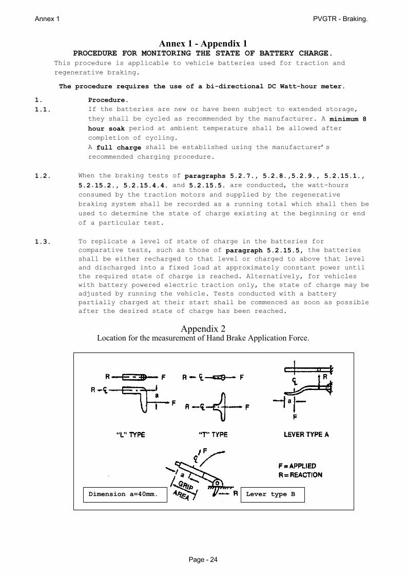
(b) Parking brake control force: Hand control <400 N ; foot control <500 N. (c) Hand force measurement locations: The force required for actuation of a hand-operated
brake system is measured at the centre of the hand grip area or at a distance of 40 mm from the end of the actuation lever. (See Appendix 2 for other alternatives.)
(d) Parking brake applications: 1 application and up to 2 re-applications, if necessary. (e) Test surface gradient: 20% grade. (f) Drive the vehicle onto the grade with the longitudinal axis of the vehicle in the direction
of the slope of the grade. (g) Stop the vehicle and hold it stationary by applying the service brake control and place
the transmission in neutral. (h) With the service brake applied sufficiently to just keep the vehicle from rolling, apply the
parking brake as specified in (b) above. (i) For a vehicle equipped with mechanically-applied parking brakes, make a single
application of the parking brake control with a force not exceeding the limits specified in (b) above.
For a vehicle using a parking brake with electrical control transmission/actuation, apply the parking brake by operating the parking brake control.
(j) Following the application of the parking brakes, release all force on the service brake
control and, if the vehicle remains stationary, start the measurement of time. (k) If the vehicle does not remain stationary, reapplication of a force to the parking brake
control at the level specified in (b) above, as appropriate for the vehicle being tested (without release of the ratchet or other holding mechanism of the parking brake) is allowed up to two times, to attain a stationary holding position.
(l) Verify the operation of the parking brake application indicator. (m) Following observation of the vehicle in a stationary condition for the specified time in
one direction, repeat the same test procedure with the vehicle being held in the opposite direction on the same grade.
5.2.14.3. Performance requirement. The parking brake system shall hold the vehicle stationary
on the 20% grade for 5 minutes pointing in both upward and downward directions. 5.2.14.4. Test of an Electric Parking brake (EPB) in the failed case.

Annex 1 PVGTR - Braking.
Page - 20
Under the same conditions of 5.2.14.2. apply a single electrical failure to the EPB circuit and check that a driver warning is produced. Actuate the parking brake control and check that this warning is given by the Red signal and is flashing and this is continued for at least 10 seconds after the ignition switch is turned off.
In the failed condition, check that the vehicle can be held on an 8% up or down grade. If
this cannot be met using the parking brake alone, check that it can be met by additionally engaging the low or reverse gear or by the Automatic Transmission in the Park position.
5.2.15. Type-I test (fade and recovery test) General information. This is a 4-part laden vehicle test designed to expose service braking performance when
the brakes are hot through excessive use. There is a heating phase achieved by snub applications and followed by a hot test to assess the fall in braking efficiency.
Part 3 is a sequence of 4 brake cooling stops which, because of the distance travelled between stops, allows cooling and some normalization of service braking effectiveness.
This is followed by 2 stops to show the recovery in service braking performance.
5.2.15.1. Heating procedure - braking snubs.
The service brakes of all vehicles must be heated by successively applying and releasing the brakes 15 times, in the following conditions:
5.2.15.1.1. Vehicle conditions
(a) Vehicle laden only (b) Transmission: in gear – using the gearbox so as to accelerate back to the start speed
v1 in the shortest possible time and holding the highest gear (excluding overdrive) during the braking phases.
5.2.15.1.2. Test conditions and procedures. (a) Establish an IBT before the first brake application which is between 55 and 65
oC
and the following snubs take place at the temperature which has been reached. (b) Number of snubs: 15: (c) The initial speed for each snub is 80% of the maximum speed of the vehicle vmax but
not exceeding 120 km/h. Each snub is terminated at ½ the initial speed. (d) Deceleration rate: Attain the specified deceleration rate of 3.0 m/s2 on each snub and adjust the pedal
force to maintain this rate constant for the remainder of each snub. (e) Time interval: Maintain a time cycle ∆t which gives an interval of 45 seconds between the start of
each snub application yet allows a 10 second period in the cycle for stabilizing the speed at v1.
(f) Immediately after completion of the 15th snub accelerate to 100 km/h and commence the Hot Performance test.
5.2.15.1.3. Special practical considerations. (a) If the characteristics of the vehicle make it impossible to abide by the duration
prescribed for ∆t , this duration may be increased; in any event, in addition to the time necessary for braking and accelerating the vehicle, it is still necessary to allow a period of 10 seconds in each cycle for stabilizing the speed v1 .
(b) For vehicles not having sufficient power to carry out the cycles of
heating of the brakes, the tests shall be carried out by achieving

PVGTR - Braking Tests
Page - 21
the prescribed speed before the first braking application and thereafter by using the maximum acceleration available to regain speed and then braking successively at the speed reached at the end of each 45 second cycle duration.
(c) For vehicles equipped with an electric regenerative braking system
of category B, the condition of the vehicle batteries at the start of the test, shall be such that the braking force contribution provided by the electric regenerative braking system does not exceed the minimum guaranteed by the system design. This requirement is deemed to be satisfied if the batteries are at one of the state of charge conditions as listed in paragraph 5.2.7.2.1. above.
5.2.15.2. Hot performance At the end of the Type-I test the hot performance of the service braking system must be
measured in the same conditions (and in particular at a mean control force no greater than the mean force actually used) for the Type-0 test with the engine disconnected (the temperature conditions should be quite different).
5.2.15.2.1. Vehicle conditions. (a) Vehicle laden. (b) Transmission in neutral
5.2.15.2.2. Test conditions and procedure. (a) IBT: The hot temperature attained by the heating process just completed.
(b) Number of stops: 2. (a second stop may be omitted if both requirements are met on the first stop.
(c) Pedal force on the 1st stop: at a mean control force no greater than the mean force actually used for the Type-0 cold performance test.
The second stop is made with a greater pedal force but not exceeding 500 N. (d) The test is made on a high adhesion surface and no wheel locking for longer than 0.1
seconds is allowed at speeds greater than 15 km/h. (e) Accelerate to 100 km/h and make the first stop. If the vehicle is incapable of attaining 100 km/h, it is tested at the same speed as was
used in the laden Type 0 cold effectiveness test. (f) In the case of vehicles equipped with an electric regenerative
braking system of category B, having carried out the heating cycles according to paragraph 5.2.15.1.2. or 5.2.15.1.3. of this Annex as appropriate, the hot performance test shall be carried out at the maximum speed which can be reached by the vehicle at the end of the brake heating cycles, but not exceeding 100 km/h.
(g) Immediately after the completion of the first hot performance stop, accelerate
rapidly back to the start speed used in (e) and conduct the second hot performance stop unless the required performance is completely satisfied by the performance of the first stop.
(h) Immediately after the completion of the second hot performance stop, or the first if
there was only one was necessary, drive 1.5 km at 50 km/h so as to be ready to make the first cooling stop.
5.2.15.2.3. Performance requirements. (a) This hot performance of the first stop shall not be less than 60% of the MFDD
recorded in the laden Type-0 test with the engine disconnected.
Annex 1 PVGTR - Braking.
Page - 22
(b) This hot performance of the second stop shall not be less than 75% of that prescribed for the Type 0 cold effectiveness - MFDD of 4.83 m/s2 or stopping distance S < 0.1v + 0.0079v2 (where v is the test speed used)
Both performance criteria may be achieved on the first stop but the second stop shall not be used to meet requirement (a).
5.2.15.3. Brake cooling stops. 5.2.15.3.1. Vehicle conditions, (a) Vehicle laden only. (b) Transmission: In gear. 5.2.15.3.2. Test conditions and procedures. (a) IBT: Temperature achieved at the end of the hot performance test (b) Test speed: 50km/h. (c) Pedal force: Adjusted as necessary to maintain a constant 3.0 m/s2 deceleration. (d) No locking of any wheel for longer than 0.1 seconds is allowed at speeds greater
than 15 km/h. (e) Number of runs; 4 stops. (f) Immediately after the hot performance stops, drive 1.5 km at 50 km/h before making
the first stop in this sequence. (g) For the 1st, 2nd and 3rd stops, immediately accelerate at the maximum rate, back to 50
km/h and maintain this speed until beginning the next stop at a distance of 1.5 km beyond the beginning of the previous stop.
(h) Make the 4th stop in the sequence and accelerate at the maximum rate to a speed of 100 km/h or the maximum speed attainable in 1.5 km.
(i) After 1.5 km at the set or achieved speed. the Recovery performance can be assessed.
(j) Vehicles equipped with an electrical regenerative braking system of category B may, unless they are charged by an on-board electricity generator, have their batteries re-charged or replaced by a charged set, in order to complete the recovery procedure.
5.2.15.4. Recovery performance test. Except in the case of (j) above, the recovery performance is conducted immediately
after the brake cooling stops. 5.2.15.4.1. Vehicle conditions. (a) Vehicle laden. (b) Transmission in neutral 5.2.15.4.2. Test conditions and procedure. (a) IBT: Temperature resulting after completion of the cooling stops. (b) Test speed: 100 km/h. (c) Pedal force: made at a mean control force no greater than the mean force actually
used for the Type-0 cold performance test. (d) The test is made on a high adhesion surface and no wheel locking for longer than 0.1
seconds is allowed at speeds greater than 15 km/h. (e) Number of runs: 2 stops. (f) After accelerating to speed and travelling for 1.5 km as in paragraph 5.2.15.3.2.( i ), make the first recovery stop from the attained speed noting the deceleration
(MFDD) achieved.

PVGTR - Braking Tests
Page - 23
(g) Accelerate again up to the previous start speed and repeat the test at the same pedal effort, noting again, the deceleration (MFDD) achieved.
5.2.15.4.3. Recovery performance required. The highest MFDD figure shall be not less than 70% nor more than 150% of the
figure recorded in the laden Type 0 cold performance test. 5.2.15.4.4. Recovery test for vehicles with electrical regenerative braking.
For vehicles equipped with an electrical regenerative braking system of category B, the recovery test shall be made by the above procedure and with the above requirement, but with all regenerative braking disabled.
5.2.15.4.5. Following the recovery process and test, further reconditioning
of the linings shall be permitted before a repeat laden vehicle Type-0 test with cold brakes shall be made from the same speed as was used in the recovery performance test of section 5.2.15.4.2. but made with the regenerative braking system disabled. The comparison of clause 5.2.15.4.3. is made between the recovery performance and this repeat Type 0 performance.
5.2.15.5. Hot performance comparison for vehicles with electric regenerative braking A second repeat laden Type-0 cold performance test shall be made
from the same speed and with a similar electric regenerative braking contribution, as set by an appropriate state of battery charge as was available during the hot performance test of section 5.2.15.2.2. above The Hot performance comparison is made between the deceleration achieved on this second cold performance test and that achieved in the hot test of section 5.2.15.2.2., against the criteria set out in paragraphs 5.2.15.2.3.
Annex 1 PVGTR - Braking.
Page - 24
Annex 1 - Appendix 1 PROCEDURE FOR MONITORING THE STATE OF BATTERY CHARGE.
This procedure is applicable to vehicle batteries used for traction and regenerative braking.
The procedure requires the use of a bi-directional DC Watt-hour meter.
1. Procedure. 1.1. If the batteries are new or have been subject to extended storage,
they shall be cycled as recommended by the manufacturer. A minimum 8 hour soak period at ambient temperature shall be allowed after completion of cycling. A full charge shall be established using the manufacturer’s recommended charging procedure.
1.2. When the braking tests of paragraphs 5.2.7., 5.2.8.,5.2.9., 5.2.15.1.,
5.2.15.2., 5.2.15.4.4. and 5.2.15.5. are conducted, the watt-hours consumed by the traction motors and supplied by the regenerative braking system shall be recorded as a running total which shall then be used to determine the state of charge existing at the beginning or end of a particular test.
1.3. To replicate a level of state of charge in the batteries for comparative tests, such as those of paragraph 5.2.15.5, the batteries shall be either recharged to that level or charged to above that level and discharged into a fixed load at approximately constant power until the required state of charge is reached. Alternatively, for vehicles with battery powered electric traction only, the state of charge may be adjusted by running the vehicle. Tests conducted with a battery partially charged at their start shall be commenced as soon as possible after the desired state of charge has been reached.
Appendix 2
Location for the measurement of Hand Brake Application Force.
Dimension a=40mm. Lever type B
![REGENERATIVE BRAKING SYSTEM IN ELECTRIC VEHICLES · REGENERATIVE BRAKING SYSTEM IN ELECTRIC VEHICLES ... REGENERATIVE BRAKING SYSTEM ... Regenerative action during braking[9]](https://img.pdfslide.us/doc/110x75/5adccef67f8b9a1a088c7cf0/regenerative-braking-system-in-electric-vehicles-braking-system-in-electric-vehicles.jpg)


![Abstract - IRCOBI10 m/s2, and the duration was 0.2 s [15]. Secondly, validation data was developed by conducting vehicle tests with autonomous braking. The vehicle tests (Volvo XC60)](https://img.pdfslide.us/doc/110x75/5f44cdf48817411585382a5b/abstract-10-ms2-and-the-duration-was-02-s-15-secondly-validation-data-was.jpg)