Embed Size (px)
Citation preview
4.9 FEM Modelling of C/C-SiC Tube Jointsfor an Ultra High Temperature Heat Exchanger
Kemal Turan, Siegfried Schmauder
1. Problem
New power generation plants will have to be cleaner and more efficient. TheExternally-Fired-Combined-Cycle with efficiencies of 50% presents one of thepromising options in this aspect [1]. Ceramic Matrix Components are currentlythe most suitable material class for this application with operatingtemperatures up to 1600°C [2]. The thermomechanical behavior of the CFRCMC based tube/tube joints for a bayonet assembly has been analysed withFE-Programme ABAQUS. The resulting stresses have been evaluated and theinfluence of several design parameters on these stresses has beeninvestigated
2. Geometry
The joint proposal shown in Fig. 1 of the possible tube/tube joint designs hasbeen chosen for a first thermomechanical analyses [1]. The dimensions of thejoint used in the present analysis are given below :
Tube diameter : 70 mm
Wall thickness of the tube: 5 mm
Wall thickness of the ring . 5 mm
Thickness of the coating : 0.1 mm
Thickness of the braze : 0.5 mm
326
60
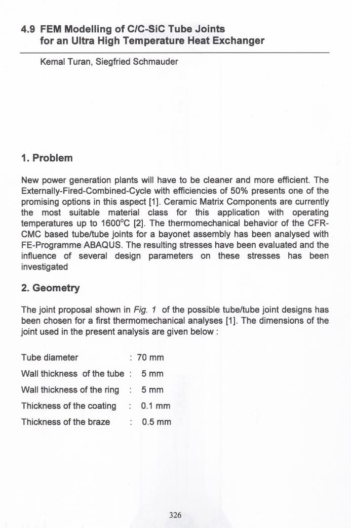
The tube and outer ring are assumed to be coated inside and outside by aceramic coating. The tubes are joined by means of a high temperatureresistarit metallic alloy (braze).
o00
(SI
ot'(SI I ~----------------------------------------
Fig. 1. Joint design proposal for brazed tube/tube joints
3. Finite-Element Mesh
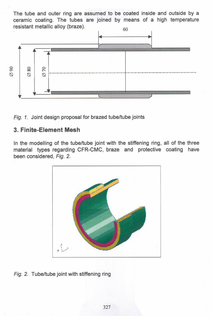
In the modelling of the tube/tube joint with the stiffening ring, all of the threematerial types regarding CFR-CMC, braze and protective coating havebeen considered, Fig. 2.
.<,\ .
~ ~.•..,•...•.. '
Fig. 2. Tube/tube joint with stiffening ring
327
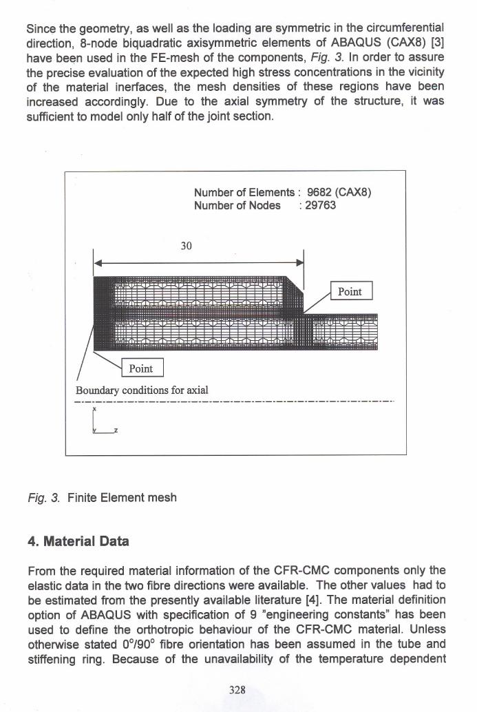
Sinee the geometry, as weil as the loading are symmetrie in the eireumferentialdireetion, 8-node biquadratie axisymmetrie elements of ABAQUS (CAX8) [3]have been used in the FE-mesh of the eomponents, Fig. 3. In order to assurethe preeise evaluation of the expeeted high stress eoneentrations in the vieinityof the material inerfaees, the mesh densities of these regions have beeninereased aeeordingly. Due to the axial symmetry of the strueture, it wassuffieient to model only half of the joint seetion.
Numberof Elements: 9682 (CAX8)Numberof Nodes : 29763
Boundary conditions for axial
Fig. 3. Finite Element mesh
4. Material Data
From the required material information of the CFR-CMC eomponents only theelastie data in the two fibre direetions were available. The other values had tobe estimated from the presently available literature [4]. The material definitionoption of ABAQUS with speeifieation of 9 "engineering eonstants" has beenused to define the orthotropie behaviour of the CFR-CMC material. Unlessotherwise stated 0°/90° fibre orientation has been assumed in the tube andstiffening ring. Beeause of the unavailability of the temperature dependent
328
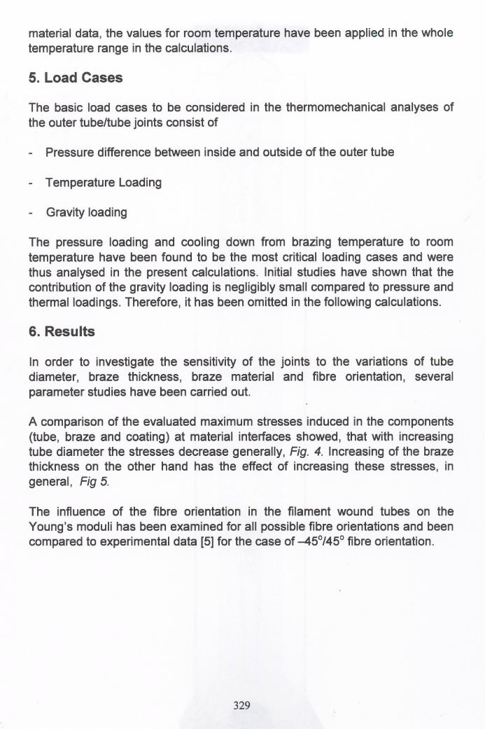
material data, the values for room temperature have been applied in the wholetemperature range in the calculations.
5. Load Cases
The basic load cases to be considered in the thermomechanical analyses ofthe outer tube/tube joints consist of
- Pressure difference between inside and outside of the outer tube
- Temperature Loading
- Gravity loading
The pressure loading and cooling down from brazing temperature to roomtemperature have been found to be the most critical loading cases and werethus analysed in the present calculations. Initial studies have shown that thecontribution of the gravity loading is negligibly small compared to pressure andthermalloadings. Therefore, it has been omitted in the following calculations.
6. Results
In order to investigate the sensitivity of the joints to the variations of tubediameter, braze thickness, braze material and fibre orientation, severalparameter studies have been carried out.
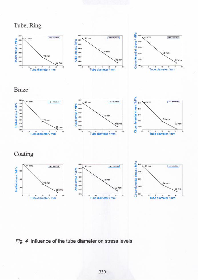
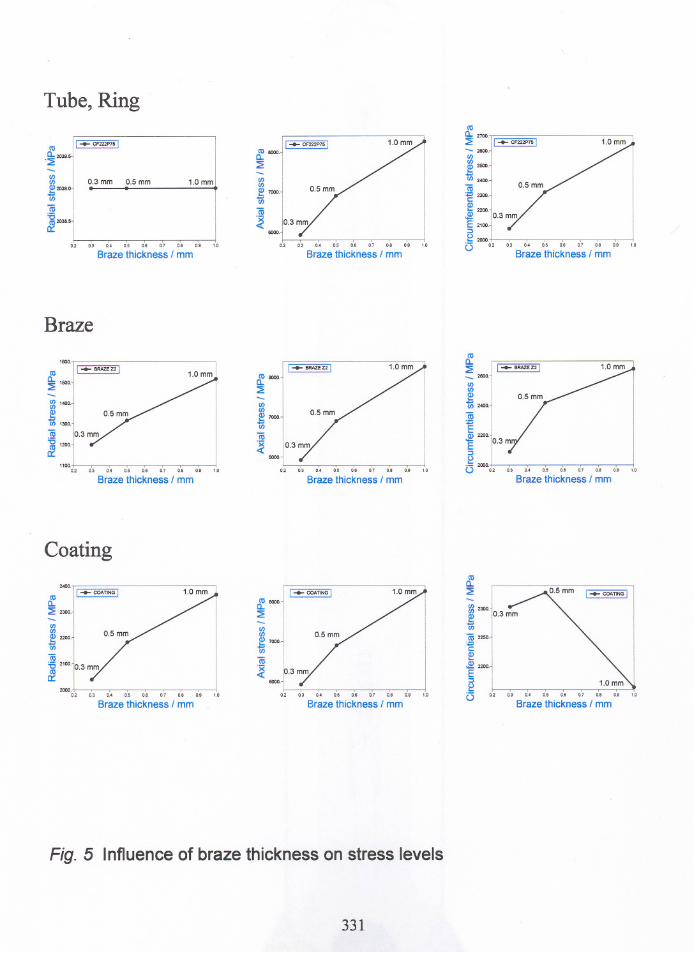
A camparisan of the evaluated maximum stresses induced in the components(tube, braze and coating) at material interfaces showed, that with increasingtube diameter the stresses decrease generally, Fig. 4. Increasing of the brazethickness on the other hand has the effect of increasing these stresses, ingeneral, Fig 5.
The influence of the fibre orientation in the filament wound tubes on theYoung's moduli has been examined for all possible fibre orientations and beencompared to experimental data [5] for the case of -45°/45° fibre orientation.
329
Tube, Ring
Tube diameter I mm
Braze
'"
CI) 692'CI)
Q)
~6S00
15 6880
~6860
"40 "
I -+- CF222P75 I
Tube diameter I mm
I-+- CF222P7sl
231°1I
23001 ,40 50 60 70 80 l
Tube diameter I mm
«la.::2-CI)CI)~1ii(ij 1320:a 1310«la::,:lOO
60 70
Tube diameter I mm
«la.I -+- BRAZf Z2 I
::2-CI)CI)~~ 692°l
1ii
Q)
~
ro~6900
~ro"'"
~
~"'"
92mm.S1
E::s6840
e"
"6070so"'" ÜTube diameter I mm
Tube diameter I mm
Coating
CI)CI)
Q) 2185.=CI)
ro~ 2180
~
I ~COATINGI
I ,~ ~ ro ro 00
Tube diameter I mm
6840 "
I -+- COATiNG I
50 60 ro 80 00
Tube diameter I mm
I -+- COATING I
so 70
Tube diameter I mm
I\00
Fig. 4 Influence of the tube diameter on stress levels
330
Tube, Ring
05 0.6 0.7
Braze thickness I mm
0.3 mm 0.5 mm..
0.5 0.6 0.7 0.6
Braze thickness I mm
<ll
a.. 2700.
::2:
-2600.'"
lß25001.::: ,cn 2400.
(ij;:; 2300.C~ 2200.
.!!1
E 2100.
:>~ 2000
C3 0.2
Braze thickness I mm
'"'"~ 7000.
Ci)
(ij~
<ll sooo.a.::2:
1.0mm
co 11 ••••• CF222P7S1
0..2039.5-
"::2:-'"'"
~2039.o-'"(ij~2038.5er:
Braze
1100.0.2
Braze thickness I mm
<ll
~ I -+- BRAZE Z2 I_2600.'"'"
~{/) 2400.
(ij+::EQ) 2200.
E 10.3m:>
J; 2000.
() 0.27.0
I ..••. BRAZEZ2 I
Braze thickness I mm
'"'"e! 7000.
Ci)
(ij
~ t3mm8000 /
0.2 03
<ll8000.a.::2:
1.0mm
0.7
Braze thickness I mm
I~ BRAZEZ21
f/) 1400.'"
~CJ) 1300.
(ij~1200.
f2.
<ll
a. 1500.
::2:
Coating
0.4 05 0.6 0.7 0.8
Braze thickness I mm0.'
<lla.::2:-~2300.
~Ci)
~2250.
'E~
~2200
E .~
C3
sooo.
'"'"
g7000.'"(ij~
0:6
Braze thickness I mm
<ll8000.a.::2:
01
Braze thickness I mm
I ..•.. COATING I
2000.0.2
2<00.
<lla.::2: 2300.
'"'"~ 2200.
Ci)
(ij'C 2100·10.3 mm
f2.
Fig. 5 Influence of braze thickness on stress levels
331
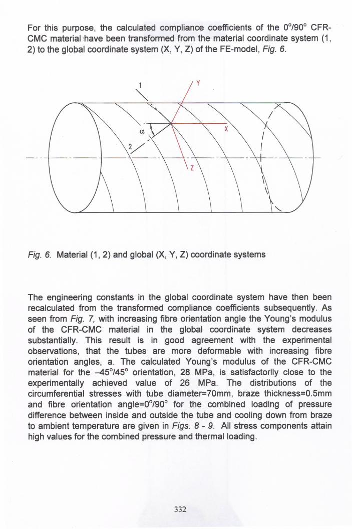
For this purpose, the ealeulated eomplianee eoeffieients of the 0°/90° CFRCMC material 'have been transformed from the material eoordinate system (1,2) to the global eoordinate system (X, Y, Z) of the FE-model, Fig. 6.
Fig. 6. Material (1,2) and global (X, Y, Z) eoordinate systems
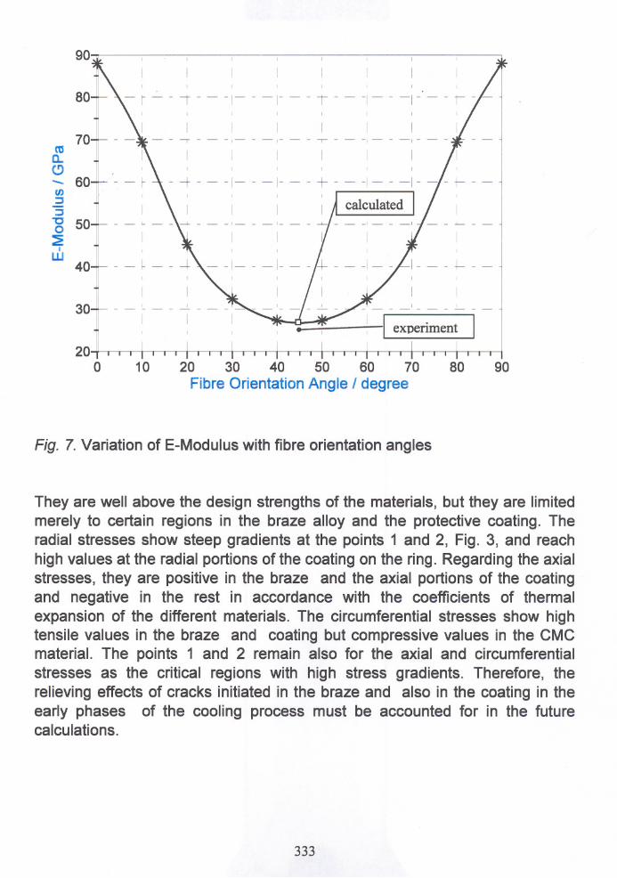
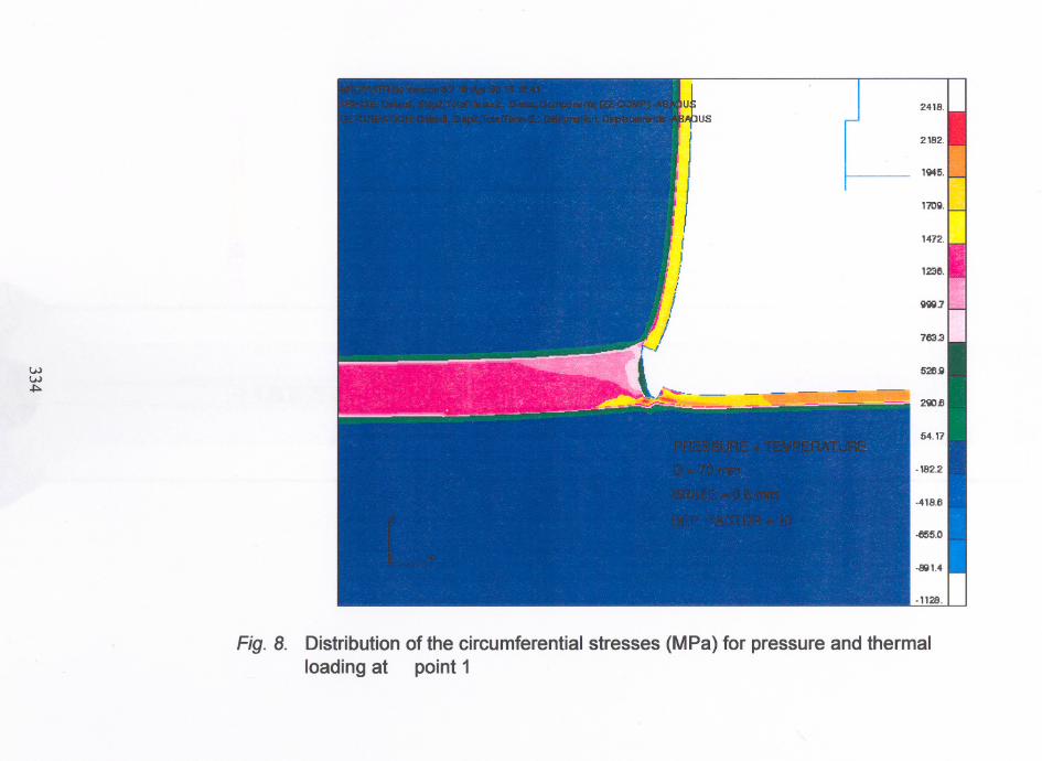
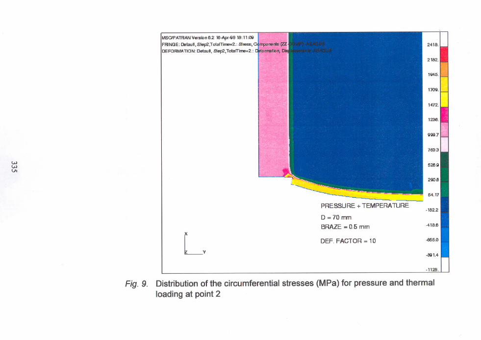
The engineering eonstants in the global eoordinate system have then beenreealeulated from the transformed eomplianee eoeffieients subsequently. Asseen from Fig. 7, with inereasing fibre orientation angle the Young's modulusof the CFR-CMC material in the global eoordinate system deereasessubstantially. This result is in good agreement with the experimentalobservations, that the tubes are more deformable with inereasing fibreorientation angles, a. The ealeulated Young's modulus of the CFR-CMCmaterial for the -45°/45° orientation, 28 MPa, is satisfaetorily elose to theexperimentally aehieved value of 26 MPa. The distributions of theeireumferential stresses with tube diameter=70mm, braze thiekness=0.5mmand fibre orientation angle=00/900 for the eombined loading of pressuredifferenee between inside and outside the tube and eooling down fram brazeto ambient temperature are given in Figs. 8 - 9. All stress eomponents attainhigh values for the eombined pressure and thermalloading.
332
9080
[ experiment•
20 30 40 50 60 70
Fibre Orientation Angle I degree10
90
8070
cu 0.."- 60rn:J:J"'0 500~ IW 40
3020
0
Fig. 7. Variation of E-Modulus with fibre orientation angles
They are weil above the design strengths of the materials, but they are limitedmerely to certain regions in the braze alloy and the protective coating. Theradial stresses show steep gradients at the points 1 and 2, Fig. 3, and reachhigh values at the radial portions of the coating on the ring. Regarding the axialstresses, they are positive in the braze and the axial portions of the coatingand negative in the rest in accordance with the coefficients of thermalexpansion of the different materials. The circumferential stresses show hightensile values in the braze and coating but compressive values in the CMCmaterial. The points 1 and 2 remain also for the axial and circumferentialstresses as the critical regions with high stress gradients. Therefore, therelieving effects of cracks initiated in the braze and also in the coating in theearly phases of the cooling process must be accounted for in the futurecalculations.
333
ww~
iusIJ
/
Fig. 8. Distribution of the circumferential stresses (MPa) for pressure and thermalloading at point 1
-1128.
-8'il1.4
-418.6
-182.2
-655.0DEF. FACTOR = 10
--~~~-~'=~~- -~~ ----PRESSURE+TEMPERATURE
D =70 mm
BRAZE = 0.5 mm
"
I '"I I
~.
L,
MSClP ATFiAN \/ersio n 6.2 16.Apr -'il8 18: 11:O\l
FFiIIlß E: Delau H,Slep2 ,ToIaITilT1ll=2.: SI ress, C,mpo nen1s (Z2jDEFOFiMATION: DetauH, Slep2,ToIaITiIT1ll=2.: ~ormation, D:
wwVI
Fig. 9. Distribution of the circumferential stresses (MPa) for pressure and thermalloading at point 2
Consideration of the modified material properties of the CFR-CMC near thebraze in the form of a material gradient in the CMC (zone affected by thebraze, ZAB) will also have an overall stress reducing effect in the componentsand must be accounted for in a separate material model.
7. Conclusion
The calculations with mostly estimated material data have shown that thethermal loading during the cooling down fram brazing temperature is the mostcritical load case. With the availability of the temperature dependent elasticplastic material data,a precise assessment of the stresses is anticipated in the future calculations.The meso- and micromechanical analyses of the brazed CMC joints with thedetermination of crack initiation sites and the prediction of the crackpropagation direction are also the targeted aims of our planned activities.
8. Acknowledgement
The support of the European Community under grant BE-3089-BRPR-CT970426 is gratefully acknowledged.
9. References
[1] Development and application of design and integration technologies forindustrial sub-critical components based on CMC-materials, Brite-Euramproject BE3089-BRPR-CT97-0426, UHTHE I EFCC I B4
[2] DOE, Power Engineering, June 1995
[3] ABAQUS, User's Manual, Version 5.6. Hibbit, Karlsson & Sorenson, Inc.
[4] W. Uns, K. Kromp. Determination of Young's Modulus and Shear Moduli ofAnisotropic Materials to Temperatures Beyond 2000°C by the ResonantBeam Method. Proc. of COST 510 workshop, June 97, Smolenice,Siovakia.
[5] M. Labanti, ENEA. Personal information
336
Advanced Ceramies
and Composites -Neue keramische Werkstoffeund Verbundwerkstoffe
6th Interregional European Colloquium on Ceramics and Composites6. Interregionales Europäisches Kolloquium über Keramik undVerbundwerkstoffe -IEKC 6
Rainer Gadow (Ed.)and 145 Co-Authors
With 259 Illustrations, 39 Tables and 428 References
Die Deutsche Bibliothek - ClP-Einheitsaufnahme
Advanced ~ramics and composites = Neue keramische Werkstoffe und Verbundwerkstoffe 16th Inter
regional European Colloquium on Ceramics andComposites. Rainer Gadow (ed.) ... - RenningenMalmsheim : expert-Verl., 2000
ISBN 3-8169-1830-1
ISBN 3-8169-1830-1
Bei der Erstellung des Buches wurde mit großer Sorgfalt vorgegangen; trotzdem können Fehlernicht vollständig ausgeschlossen werden. Verlag und Autoren können für fehlerhafte Angaben undderen Folgen weder eine juristische Verantwortung noch irgendeine Haftung übernehmen.Für Verbesserungsvorschläge und Hinweise auf Fehler sind Verlag und Autoren dankbar.
@ 2000 by expert verlag, 71272 Renningen, http://www.expertverlag.deAlle Rechte vorbehaltenPrinted in Germany
Das Werk einschließlich aller seiner Teile ist urheberrechtlich geschützt. Jede Verwertung außerhalb der engen Grenzen des Urheberrechtsgesetzes ist ohne Zustimmung des Verlags unzulässigund strafbar. Dies gilt insbesondere für Vervielfältigungen, Übersetzungen, Mikroverfilmungen unddie Einspeicherung und Verarbeitung in elektronischen Systemen.