Embed Size (px)
Citation preview
FEEDWATER HEATERS
Straight Tube Types
U - Tube Types
Duplex Types
ATFD-Agitated Thin film Dryers
Challenging Perfection the Limits of Technological
Range of Feed Water Heaters
Features of Chem Process Systems Feed Water Heaters
Feed water Heater Highlights:
Feed water Heater Design Features:
Design of Feedwater Heaters
We offer the complete range of feedwater heaters for nuclear and large-
scale conventional power plants:
· U-type feedwater heaters
· Duplex heaters with U-tube bundles
· Heaters with Drain Cooling and steam desuperheating sections
· Special constructions such as U-tube duplex heaters
· Optimized tube bundle venting system to enhance performance
· Design, manufacture and erection from one source
· Proven by reference
· Plant sizes from 2- 150 MWe plant capacity
· Vertical or horizontal designs for both LP and HP units
· LP/HP Heaters with U-tubes
· Duplex heaters with U-tubes
· Independent desuperheating zone closures
· Baffle configuration and spacing based on conservative mass velocity
criteria
· Fully enclosed self- venting drains sub- cooling zones
· Liberal sub-cooling zone entrance areas to permit low approach
velocities which prevent flashing of saturated drains
· Internal, centrally located venting arrangement to provide a positive
means of continuously venting condensing zone
· Channel cover configurations for all nozzle layouts
· Fully automated tube-to-tubes sheet welding procedures
· Hydraulic or conventional tube expansion assuring consistently
reliable tube joints
Each feed water heater will contain one to three separate heat transfer
areas or zones including the condensing, desuperheating and sub-
cooling zones. Economics of design and plant requirements will
determine the design parameters of the feed water heaters.
For feedwater heaters, the tube material, tube diameter and water velocity are
selected based on the calculation of operational economy and safety. For LP
heaters the tubes are expanded by rolling into the tube sheet. For HP heaters
the tubes are welded to the tubesheet followed by a light expansion. The
bundle carrier is designed such that the tubes are protected against
deformation and vibration and can freely expand. The support plates with the
tube bundles can freely move in longitudinal and cross direction, despite the
unequal thermal expansion due to the hot and cold tube leg. The support
plates show furthermore supports in the shape of wings in order for lateral
guidance of the bundle carrier at the inner wall of the steam shell. The bundle
carrier consists of support plates, side metal sheets, spacers and tie- rods which
can be economically assembled quickly and with little welding work.
A low – pressure feedwater preheater or heater in power plants, heated with
bleed steam and having a two- pass tube bundle of the tube sheet type of
construction, has a carrier design for the tube bundle having side plates
running parallel to the tube bundle and one or more supporting plates
disposed perpendicularly to the tube bundle. In the center of the bundle
between the cold and the hot leg are suction tubes through which non-
condensable gases are drawn off in the zones of lowest pressure. The
supporting plates are each made of a single piece and are thus continuous, and
the partition consists of individual sheet- metal parts which are connected to
the supporting plates. In one embodiment, the sheet-metal parts of the
Low Pressure-LP Feedwater Heaters
partition and the supporting plate are connected to
one another by indentations on each side of the
sheet- metal part which faces the supporting plate
and by a corresponding opening in the supporting
plate.
LP Feed Water Heaters are designed as single zone
with a condensing section or two zones with a
condensing section and integral sub cooler section.
Drain coolers are employed because of heat
consumption improvement in case of drain
introduction into the lower heater through the level
control valve. Condensing heaters without sub
cooler section have a better heat consumption if the
drain flows forward by using a drain pump. A drain
pump is used usually for the drain of LP heaters.
Tube sheet HP Heaters are designed as two zones or three zones with a
condensing section, desuperheater and integral sub cooler.
The use of a desuperheater reduces the terminal temperature difference (TTD)
of the entire Feedwater Heater. A negative TTD of up to 3°C can be achieved
by the use of a desuperheater, depending on the steam inlet temperature. The
tube wall temperature must be over the local saturation temperature in all
operation conditions.
The use of a separate cross-connected desuperheater improves the heat
consumption and increases the feed water temperature at the boiler inlet.
Drain cooler are employed because of heat consumption improvement in case
of drain introduction into the lower heater through the control valve.
These type of HP Feedwater Heaters have been developed to meet the
increasingly severe operating conditions in large turbo generator plants. These
may include high heat rates, sudden load variations and frequent start-ups and
shut –downs in case of peak- load power plants.
In the low pressure section, our duplex heaters allow the extraction steam
piping to be routed in a functional and space saving manner. They unite two
heater stages in one single shell and replace two heaters arranged in a row.
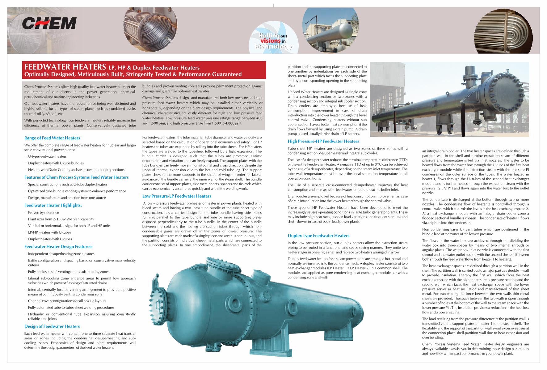
Duplex feed water heaters for a steam power plant are arranged horizontal and
normally are inserted into the condenser neck. A duplex heater consists of two
heat exchanger modules (LP Heater 1/ LP Heater 2) in a common shell. The
modules are applied as pure condensing heat exchanger modules or with a
condensing zone and with
High Pressure-HP Feedwater Heaters
Duplex Type Feedwater Heaters
an integral drain cooler. The two heater spaces are defined through a
partition wall in the shell and turbine extraction steam of different
pressure and temperature is fed via inlet nozzles. The water to be
heated flows from the water box through the U-tubes of the first heat
exchanger module while the extraction steam with the pressure PI
condenses on the outer surface of the tubes. The water heated in
heater 1, flows through the U- tubes of the second heat exchanger
module and is further heated through the extraction steam with the
pressure P2 (P2 P1) and flows again into the water box to the outlet
nozzle.
The condensate is discharged at the bottom through two or more
nozzles. The condensate flow of heater 2 is controlled through a
control valve which controls the levels in the heat exchanger space 2.
At a heat exchanger module with an integral drain cooler zone a
flooded sectional bundle is chosen. The condensate of heater 1 flows
via a siphon into the condenser.
Non condensing gases by vent tubes which are positioned in the
bundle lane at the zones of the lowest pressure.
The flows in the water box are achieved through the dividing the
water box into three spaces by means of two internal shrouds or
angular plates. The water box inlet nozzle is connected with the first
shroud and the water outlet nozzle with the second shroud. Between
both shrouds the feed water flows from heater 1 to heater 2.
The heat exchanger spaces are defined through a partition wall in the
shell. The partition wall is carried out to a major part as a double – wall
to provide insulation. Thereby the first wall which faces the heat
exchanger space with the higher pressure is pressure bearing and the
second wall which faces the heat exchanger space with the lower
pressure serves as heat insulation and manufactured of thin sheet
metal. For transmitting the force between the two walls thin metal
sheets are provided. The space between the two walls is open through
a number of holes at the bottom of the wall to the steam space with the
lower pressure P1. The insulation provides a reduction in the heat loss
flow and a power saving.
The load resulting from the pressure difference at the partition wall is
transmitted via the support plates of heater 1 to the steam shell. The
flexibility and the support of the partition wall avoid excessive stress at
the connection place shell-partition wall due to heat expansion and
over bending.
Chem Process Systems Feed Water Heater design engineers are
always available to assist you in determining those design parameters
and how they will impact performance in your power plant.
FEEDWATER HEATERS LP, HP & Duplex Feedwater HeatersOptimally Designed, Meticulously Built, Stringently Tested & Performance Guaranteed
Chem Process Systems offers high quality feedwater heaters to meet the
requirement of our clients in the power generation, chemical,
petrochemical and marine engineering industries.
Our feedwater heaters have the reputation of being well designed and
highly reliable for all types of steam plants such as combined cycle,
thermal oil (gas/coal), etc.
With perfected technology, our feedwater heaters reliably increase the
efficiency of thermal power plants. Conservatively designed tube
bundles and proven venting concepts provide permanent protection against
damage and guarantee optimal heat transfer.
Chem Process Systems designs and manufactures both low pressure and high
pressure feed water heaters which may be installed either vertically or
horizontally, depending on the plant design requirements. The physical and
chemical characteristics are vastly different for high and low pressure feed
water heaters. Low pressure feed water pressure ratings range between 400
and 1,500 psig, and high pressure range from 1,500 to 4,800 psig.