Embed Size (px)
Citation preview

MIL-STD-810F30 August 2002
METHOD 505.4505.4-11
4.4.1 Preparation for test
4.4.1.1 Preliminary steps.Before starting the test, review pretest information in the test plan to determine test details (e.g., procedures, itemconfiguration, cycles, durations, parameter levels for storage/operation, etc.). (See paragraph 3.1, above.)
a. Which test procedures are required.
b. The diurnal cycle to be used.
c. Other variables, such as number of cycles, etc.
d. Degree of removal of surface contamination necessary (see paragraph 4.2b).
e. Comparative information. For eventual comparison between pre- and post-test items, photograph the testitem and take material samples (if required).
4.4.1.2 Pretest standard ambient checkout.All items require a pretest standard ambient checkout to provide baseline data. Conduct the checkout as follows:
Step 1. Install the test item in the chamber and stabilize it at standard ambient conditions (Part One,paragraph 5.1a) and in a manner that will simulate service use, unless the storage configuration isspecified. Position the test item in accordance with the following:
a. As near the center of the test chamber as practical and so that the surface of the item is notcloser than 0.3m (1 ft) to any wall or 0.76m (30 in.) to the radiation source when the source isadjusted to the closest position it will assume during the test
b. Oriented, within realistic limits, to expose its most vulnerable parts to the solar radiation,unless a prescribed orientation sequence is to be followed.
c. Separated from other items that are being tested simultaneously, to ensure that there is nomutual shading or blocking of airflow unless this, also, is representative of the materiel's fielduse.
Step 2. Conduct a visual examination of the test item with special attention to stress areas, such as cornersof molded cases, and document the results.
Step 3. Prepare the test item in accordance with Part One, paragraph 5.8, and in the identified test itemconfiguration (see paragraph 2.3.3), with any temperature sensors necessary to determine test itemresponse.
Step 4. Conduct an operational checkout in accordance with the test plan and record the results.Step 5. If the test item operates satisfactorily, place it in its test configuration (if other than operational). If
not, resolve the problem and restart at Step 1. Return the test item to the position identified in Step1 and proceed to the first test as identified in the test plan.
4.4.2 Procedure I.Step 1. Adjust the chamber air temperature to the minimum value of the temperature cycle at which
radiation is nonexistent.Step 2. Expose the test item to continuous 24-hour cycles of controlled simulated solar radiation and dry-
bulb temperature as indicated on figure 505.4-1 or as identified in the requirements document,measuring and recording test item temperatures throughout the exposure period. For convenienceand if the test facility is unable to perform the continuous curve of figure 505.4-1, to approximatethe curve increase and decrease the solar radiation intensity in a minimum of four levels (preferablyeight levels) for each side of the cycle, provided that the total energy of the cycle as well as thespectral power distribution (table 505.4-I) is maintained. Perform the longer of the followingnumber of cycles:
SUPERSEDES PAGE 505.4-11 OF MIL-STD-810F.

MIL-STD-810F 1 January 2000
METHOD 505.4505.4-12
a. The minimum necessary to ensure the peak response temperature of the most critical area ofthe test item achieved during a cycle is within 2°C of the peak response temperature achievedduring the previous 24-hour cycle, or
b. Three continuous cycles, or
c. The number of cycles as identified by the requirements document (not to exceed 7 cycles).
Step 3. The test item may or may not be operated throughout the test, at the option of the requirementsdocument. If operation is required, operate the test item when the peak cycle temperature occurs.For some single-use items (e.g., rockets), use thermocouples affixed to critical portions of the testitem to determine the time and value of peak temperature. Operate the test item at the peak cycletemperature. Conduct the operational checkout of the test item as in paragraph 4.4.1.2, Step 4.Document the results.
Step 4. Adjust the chamber air temperature to standard ambient conditions and maintain until temperaturestabilization of the test item has been achieved.
Step 5. Conduct a complete visual examination of the test item and document the results. For comparisonbetween pre- and post-test items, photograph the test item and take material samples (if required).
Step 6. Conduct an operational checkout of the test item as in paragraph 4.4.1.2, Step 4.Step 7. Compare these data with the pretest data.
4.4.3 Procedure II.
Step 1. Adjust the chamber air temperature to 49°C or the temperature identified in the test plan.Step 2. Adjust the solar radiation source to a radiant energy rate of 1120 ±47 W/m2 or as identified in the
materiel specification.Step 3. Maintain these conditions for 20 hours, measuring and recording the test item temperatures. If
required, conduct operational checks during the last four hours of each 20-hour exposure when testtemperatures are maximized.
Step 4. Turn off the solar radiation source for four hours.Step 5. Repeat Steps 1 through 4 for the number of cycles identified in the test plan.Step 6. At the end of the last radiation cycle, allow the test item to return to standard ambient conditions.Step 7. Conduct a visual examination and an operational check as in paragraph 4.4.1.2, Steps 2 and 4, and
document the results. Take photographs of the test item and material samples (if required) forcomparison between pre- and post-test items.
5. ANALYSIS OF RESULTS.In addition to the guidance provided in Part One, paragraphs 5.14 and 5.17, the following information is provided toassist in the evaluation of the test results. Analyze any failure of a test item to meet the requirements of the materielspecifications.
a. Procedure I. Do not alter the performance characteristics either at the peak temperature or after return tostandard ambient conditions to the extent that the test item does not meet its requirements. Record asobservations only those actinic effects that do not affect performance, durability, or required characteristics.
b. Procedure II. Do not alter the performance and characteristics (such as color or other surface conditions) ofthe test item to the extent that the test item does not meet requirements. Record actinic effects that do notaffect performance, durability, or required characteristics as observations only. The fading of colors couldresult in higher heating levels within the test item.
6. REFERENCE/RELATED DOCUMENTS.
a. AR 70-38, Research, Development, Test and Evaluation of Materiel for Extreme Climatic Conditions.
b. MIL-HDBK-310, Global Climatic Data for Developing Military Products.
c. Synopsis of Background Material for MIL-STD-210B, Climatic Extremes for Military Equipment.Bedford, MA: AF Cambridge Research Laboratories, January 1974. DTIC number AD-780-508.
REPRINTED WITHOUT CHANGE.

MIL-STD-810F1 January 2000ANNEX A
METHOD 505.4505.4A-1
ANNEX A
DETAILED GUIDANCE ON SOLAR RADIATION TESTING
1. INTRODUCTION.This Annex describes methods of simulation designed to examine the effects of solar radiation on materiel. Themain quantities to be simulated are the spectral energy distribution of the sun as observed at the Earth's surface andthe intensity of received energy, in combination with controlled temperature conditions. However, it may benecessary to consider a combination of solar radiation - including sky radiation - with other environments, e.g.,humidity, air velocity, etc.
2. IRRADIANCE AND SPECTRAL DISTRIBUTION.The effect of radiation on the materiel will depend mainly on the level of irradiance and its spectral distribution.
2.1 Irradiance.The irradiance by the sun on a plane perpendicular to the incident radiation outside the Earth's atmosphere at themean Earth-sun distance is known as the solar constant " I0." The irradiance at the surface of the Earth is influencedby the solar constant and the attenuation and scattering of radiation in the atmosphere. For test purposes, amaximum intensity of 1120 W/m2 is specified to simulate the global (total) radiation at the surface of the Earth fromthe sun and the sky with the sun at zenith, based on a solar constant I0 = 1350 W/m2. The true solar constant isthought to be about 1365-1370 W/m2.
2.2 Spectral Distribution - Sea Level Versus High Altitude.At high altitude, solar radiation contains a greater proportion of damaging UV radiation than at sea level. Theinternationally-agreed spectrum (see table 505.4A-I) recommended for general testing is a representation of the realenvironment at 4-5 km. This spectrum is recommended for use at both sea level and at high altitude.
3. OTHER ENVIRONMENTAL FACTORS TO BE CONSIDERED.Attention is drawn to the possible cooling effects of air flow over materiel. This can also result in misleading errorsin open-type thermopiles used to monitor radiation intensity; ventilation of pyranometers may be necessary to keepthe glass dome cool. An air flow of as little as one meter per second can effect a reduction in temperature rise ofover 20%. In practice, high solar radiation conditions are rarely accompanied by complete absence of wind. It maybe necessary, therefore, to assess the effect of different air velocities over materiel under test. The materielspecification should state any special requirements in this respect. It is essential, therefore, to measure and controlthe rate of air flow in order to maintain the required air temperature at the test item.
4. RADIATION SOURCES
4.1 General.The radiation source may comprise one or more lamps and their associated optical components; e.g., reflectors,filters, etc., to provide the required spectral distribution and irradiance. The high pressure xenon arc lamp withfilters can provide the best spectral match. Mercury vapor and xenon-mercury lamps have considerable deficienciesin matching which would lead to error. The carbon arc, with specially-doped electrodes, has been widely used butpresents difficulties as regards stability and maintenance, and is therefore not generally favored. If not alreadycovered in test method characteristics of these sources, features of filters, optical arrangements, etc., are covered inthe following paragraphs. The following general information about several light sources may be helpful.
REPRINTED WITHOUT CHANGE.

MIL-STD-810F 30 August 2002ANNEX A
METHOD 505.4505.4A-2
a. Xenon lamps. The configuration and size of the lamp(s) used will depend on the test required. The relativespectral distribution of the xenon arc radiation has been found to be substantially independent of lamppower. However, variation of lamp power will change the temperature of the electrodes and hence thespectral distribution of their radiation. With long arc lamps, it is relatively simple to mask off the electroderadiation. The form of construction of the short arc lamp leads to considerably wider manufacturingvariation compared with the long arc, a point particularly important when replacement becomes necessary.Routine replacement of either type of lamp will be needed, since the emission will change continuouslywith life, and there may be wide variations of the life characteristic from lamp to lamp.
b. Metal Halide (HMI). Although this lamp imparts more energy in the ultraviolet range and low visiblerange than specified in table 505.4-I, it provides a good source for tests requiring attention to thermaleffects, since the additional UV energy represents less than one per cent of the total energy, and tests forheating effects are generally sufficiently short in duration that actinic degradation will not be a concern. Fortesting actinic effects, the energy level in the heating range will be lower than specified as the UV levelswill be adjusted to table 505.4A-I levels. Since the energy level between 0.32 and 0.40µm increases sharplyas the lamp power level is reduced, power cannot be used to adjust overall energy levels once the desireddistribution has been obtained.
4.2 Filters.
Liquid filters have certain disadvantages such as the possibility of boiling, the temperature coefficient of spectraltransmission, and long term drift in spectral character. The present preference is for glass filters to be used, althoughthe characteristics of glass filters are not as accurately reproduced as those of a chemical solution filter. Some trialand error may be necessary to compensate for different optical densities by using different plate thicknesses. Glassfilters are proprietary articles and manufacturers should be consulted concerning the choice of filters suitable forparticular purposes. The choice will depend on the source and its methods of use. For example, a xenon source maybe test-compensated by a combination of infrared and ultraviolet absorbing filters. Some glass infrared filters maybe prone to rapid changes in spectral characteristics when exposed to excessive ultraviolet radiation. Thisdeterioration may be largely prevented by interposing the ultraviolet filter between the source and the infrared filter.Interference type filters, which function by reflecting instead of absorbing the unwanted radiation, (thus resulting inreduced heating of the glass), are generally more stable than absorption filters.
4.3 Uniformity of Irradiance.
Owing to the distance of the sun from the Earth, solar radiation appears at the Earth's surface as an essentiallyparallel beam. Artificial sources are relatively close to the working surface and means of directing and focusing thebeam must be provided with the aim of achieving a uniform irradiance at the measurement plane withinspecification limits (i.e., 1120 W/m2 (+10, -0 W/m2)). This is difficult to achieve with a short-arc xenon lamp with aparabolic reflector because of shadows from the lamp electrodes and supports. Also, the incandescence of the anodecan produce considerable radiation at a much lower color temperature, slightly displaced from the main beam, ifonly the arc itself is at the focus of the reflector. Uniform irradiation is more readily achieved with a long arc lampmounted in a parabolic 'trough' type reflector. However, by employing very elaborate mounting techniques, it ispossible to irradiate, with some degree of uniformity, a large surface by a number of short arc xenon lamps. It isgenerally advisable to locate radiation source(s) outside the test enclosure or chamber. This avoids possibledegradation of the optical components, e.g., by high humidity conditions, and contamination of test items by ozonethat has been generated by xenon and other types of arc lamps. Precise collimation of the radiation beam is notnormally required except for testing special materiel such as solar cells, solar tracking devices, etc. However, some
SUPERSEDES PAGE 505.4A-2 OF MIL-STD-810F.

MIL-STD-810F30 August 2002
METHOD 506.4506.4-1
METHOD 506.4
RAINNOTE: Tailoring is essential. Select methods, procedures, and parameter levels based on the tailoring processdescribed in Part One, paragraph 4.2.2, and Appendix C. Apply the general guidelines for laboratory test methodsdescribed in Part One, paragraph 5 of this standard.
1. SCOPE.
1.1 Purpose.The purpose of this method is to help determine the following with respect to rain, water spray, or dripping water:
a. The effectiveness of protective covers, cases, and seals in preventing the penetration of water into themateriel.
b. The capability of the materiel to satisfy its performance requirements during and after exposure to water.
c. Any physical deterioration of the materiel caused by the rain.
d. The effectiveness of any water removal system.
e. The effectiveness of protection offered to a packaged materiel.
1.2 Application.Use this method to evaluate materiel likely to be exposed to rain, water spray, or dripping water during storage,transit, or operation. If the materiel configuration is the same, the immersion (leakage) test (method 512.4) isnormally considered to be a more severe test for determining if water will penetrate materiel. There is generally noneed to subject materiel to a rain test if it has previously passed the immersion test and the configuration does notchange. However, there are documented situations in which rain tests revealed problems not observed duringimmersion tests due to differential pressure. Additionally, the immersion test may be more appropriate if themateriel is likely to be placed on surfaces with significant amounts of standing water. In most cases, both testsshould be performed if appropriately identified in the life-cycle profile.
1.3 Limitations.Where a requirement exists for determining the effects of rain erosion on radomes, nose cones, fuzes, etc., considerusing a rocket sled test facility or other such facility. Since any test procedure involved would be contingent onrequirements peculiar to the materiel and the facility employed, a standardized test procedure for rain erosion is notincluded in this method. Because of the finite size of the test facilities, it may be difficult to determine atmosphericrain effects such as on electromagnetic radiation and propagation. This method is not intended for use in evaluatingthe adequacy of aircraft windshield rain removal provisions, nor does it address pressure washers ordecontamination devices. Additionally, this method may not be adequate for determining the effects of extendedperiods of exposure to rain, or for evaluating materiel exposed to only light condensation drip rates (lower than140 L/m2/hr) caused by an overhead surface. For this latter case, the aggravated humidity cycle of method 507.4will induce a significant amount of free water on both inside and outside surfaces.
2. TAILORING GUIDANCE.
2.1 Selecting the Rain Method.After examining the requirements documents and applying the tailoring process in Part One of this standard todetermine where rain is foreseen in the life cycle of the materiel, use the following to aid in selecting this methodand placing it in sequence with other methods. The term " rain " encompasses the full range of " free water"(blowing, steady-state, drip) tests included in this method.
SUPERSEDES PAGE 506.4-1 OF MIL-STD-810F.

MIL-STD-810F 1 January 2000
METHOD 506.4506.4-2
2.1.1 Effects of rain environments.Rain (when falling, upon impact, and as deposited as pooled water) has a variety of effects on materiel. Consider thefollowing typical problems to help determine if this method is appropriate for the materiel being tested. This list is notintended to be all-inclusive and some of the examples may overlap the categories.
2.1.1.1 In the atmosphere.In the atmosphere the effects resulting from exposure to these environments include:
a. Interference with or degradation of radio communication.
b. Limited radar effectiveness.
c. Limited aircraft operations due to restricted visibility and decreased lift from wing surfaces (excessive rainrates only).
d. Damage to aircraft in flight.
e. Effect on artillery and missile launching.
f. Degradation or negation of optical surveillance.
g. Decreased effectiveness of personnel in exposed activities.
h. Premature functioning of some fuses.
i. Inhibited visibility through optical devices.
2.1.1.2 On impact.On impact it erodes surfaces.
2.1.1.3 After deposition and/or penetration.After deposition and/or penetration, the effects resulting from exposure to these environments include:
a. Degraded strength/swelling of some materials.
b. Increased corrosion potential, erosion, or even fungal growth.
c. Increased weight.
d. Electrical or electronic apparatus become inoperative or unsafe.
e. Malfunction of electrical materiel.
f. Freezing inside materiel that may cause delayed deterioration and malfunction by swelling or cracking ofparts.
g. Modified thermal exchange.
h. Slower burning of propellants.
2.1.2 Sequence among other methods.
a. General. See Part One, paragraph 5.5.
b. Unique to this method. This method is applicable at any stage in the test program, but its effectiveness indetermining the integrity of an enclosure is maximized if it is performed after the dynamic tests.
2.2 Selecting Procedures.This method includes three rain-related test procedures: Procedure I (Rain and Blowing Rain), Procedure II(Watertightness), and Procedure III (Drip). Before conducting the test, determine which test procedure(s) and testconditions are appropriate.
REPRINTED WITHOUT CHANGE.

MIL-STD-810F30 August 2002
METHOD 506.4506.4-3
2.2.1 Procedure selection considerations.Differences among rain test procedures are explained below. Select the procedure that represents the most severeexposure anticipated for the materiel commensurate with materiel size. When selecting a procedure, consider:
a. The materiel configuration.b. The logistical and operational requirements (purpose) of the materiel.c. The operational purpose of the materiel and data to verify it has been met.d. The natural exposure circumstances.e. Procedure sequence.
2.2.2 Difference among procedures.a. Procedure I - Rain and Blowing Rain. Procedure I is applicable for materiel which will be deployed out-of-
doors and which will be unprotected from rain or blowing rain. The accompanying wind velocity can varyfrom almost calm to extremely high. Consider using Procedure II for materiel that cannot be adequatelytested with this procedure because of its (large) size.
b. Procedure II - Watertightness. Consider Procedure II when large (shelter-size) materiel is to be tested and ablowing-rain facility is not available or practical. This procedure is not intended to simulate natural rainfallbut will provide a high degree of confidence in the watertightness of materiel.
c. Procedure III - Drip. Procedure III is appropriate when materiel is normally protected from rain but maybe exposed to falling water from condensation or leakage from upper surfaces. There are two variations tothe drip test: (1) for materiel that may experience falling water (generally from condensation), and (2) formateriel that may be subjected to heavy condensation or leaks from above.
2.3 Determine Test Levels and Conditions.Having selected this method and relevant procedures (based on the materiel's requirements documents and thetailoring process), it is necessary to complete the tailoring process by selecting specific parameter levels and specialtest conditions/techniques for these procedures based on requirements documents, Life Cycle Environmental Profile,Operational Environment Documentation (see Part One, Figure 1-1), and information provided with this procedure.From these sources of information, determine the functions to be performed by the materiel in rain environments orfollowing storage in rain environments. Then determine the rainfall levels of the geographical areas and micro-environments in which the materiel is designed to be employed. Variables under each test procedure include the testitem configuration, rainfall rate, wind velocity, test item exposure surfaces, water pressure, and any additionalappropriate guidelines in accordance with the requirements document.
2.3.1 Test item configuration.Perform the test using all the configurations in which the materiel may be placed during its life cycle. As aminimum, consider the following configurations:
a. In a shipping/storage container or transit case.b. Protected or not protected.c. In its operational configuration.d. Modified with kits for special applications.
NOTE: Do not use any sealing, taping, caulking, etc., except as required by the design specification for the materiel.Unless otherwise specified, do not use test items that have surface contamination such as oil, grease, or dirt, whichcould prevent wetting.
2.3.2 Rainfall rate.The rainfall rate used in Procedure I may be tailored to the anticipated deployment locale and duration. Althoughvarious rainfall intensities have been measured in areas of heavy rainfall, recommend a minimum rate of1.7 mm/min (4 in/hr) since it is not an uncommon occurrence and would provide a reasonable degree of confidencein the materiel. MIL-HDBK-310 contains further information.
SUPERSEDES PAGE 506.4-3 OF MIL-STD-810F.

MIL-STD-810F30 August 2002
METHOD 506.4506.4-4
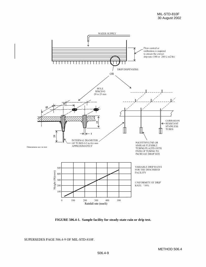
2.3.3 Droplet size.Nominal drop-size spectra exist for instantaneous rainfall rates but for the long-term rainfall rates they aremeaningless since rates are made up of many different instantaneous rates possessing different spectra (reference b).For Procedures I and II, use droplet sizes predominantly in the range of approximately 0.5 mm in diameter 1/ (whichis considered to be mist or drizzle rather than rain (reference e), to 4.5 mm in diameter (reference i). For drip testsusing dispensing tubes (figure 506.4-1), polyethylene tubing sleeves added to the dispensing tubes will increase thedroplet size to its maximum.
NOTE: Observations have shown that water droplets introduced into a high velocity air stream tend to break upover distance (references j and k). Accordingly, recommend introducing the droplets as close as possible to the testitem while assuring the droplets achieve the required velocity prior to impact with the test item.
2.3.4 Wind velocity.High rainfall intensities accompanied by winds of 18 m/s (40 mph) are not uncommon during storms. Unlessotherwise specified or when steady-state conditions are specified, recommend this velocity. Where facilitylimitations preclude the use of wind, use Procedure II.
2.3.5 Test item exposure surface (orientation).Wind-blown rain will usually have more of an effect on vertical surfaces than on horizontal surfaces, and vice versafor vertical or near-vertical rain. Expose all surfaces onto which the rain could fall or be driven to the testconditions. Rotate the item as required to expose all vulnerable surfaces.
2.3.6 Water pressure.Procedure II relies on pressurized water. Vary the pressure as necessary to comply with the requirement’sdocuments, but a minimum value of 276 kPa (40 psig) nozzle pressure is given as a guideline based on pastexperience. This value will produce water droplets traveling at approximately 64 km/h (40 mph) when a nozzle asspecified in paragraph 4.1.2 is used.
2.3.7 Preheat temperature.Experience has shown that a temperature differential between the test item and the rainwater can affect the results ofa rain test. When specified for nominally sealed items, increasing the test item temperature to about 10°C higherthan the rain temperature at the beginning of each exposure period to subsequently produce a negative pressureinside the test item will provide a more reliable verification of its watertightness. Ensure the heating time is theminimum required to stabilize the test item temperature, and not sufficient to dry the test item when not openedbetween exposures.
2.3.8 Exposure duration.Determine the exposure duration from the life-cycle profile, but do not use a duration less than that specified in theindividual procedures. For items made of material that may absorb moisture, the duration may have to besignificantly extended to reflect real life-cycle circumstances and, for drip tests, the drip rate appropriately reduced.With certain materials, the water penetration and thus the degradation is more a function of time (length ofexposure) than the volume or rain/drip rate exposure.
3. INFORMATION REQUIRED.
3.1 Pretest.The following information is required to conduct rain tests adequately.
a. General. Information listed in Part One, paragraphs 5.7 and 5.9; and Appendix A, Task 405, of thisstandard.
1/Observations show there are no drops of less than roughly 0.5 mm diameter during intense rains (reference c).
SUPERSEDES PAGE 506.4-4 OF MIL-STD-810F.
MIL-STD-810F30 August 2002
METHOD 506.4506.4-5
b. Specific to this method.
(1) Rainfall rate.
(2) Exposure surfaces/duration.
(3) Test item preheat temperature.
(4) Initial water temperature.
(5) Wind velocity.
(6) Water pressure (if appropriate).
3.2 During Test.For test validation purposes, record deviations from planned or pre-test procedures or parameter levels, includingany procedural anomalies that may occur.
3.3 Post-test.Record the following post-test information.
a. General. Information listed in Part One, paragraph. 5.13, and in Appendix A, Task 406 of this standard.
b. Specific to this method.
(1) Surfaces of the test item subjected to rainfall.
(2) Duration of exposure per face.
(3) Results of inspection for water penetration (amount and probable point of entry).
(4) Results of operational checks.
(5) Length of time for each performance check.
4. TEST PROCESS.
4.1 Test Facility.
4.1.1 Procedure I.
a. Use a rain facility capable of producing falling rain at the rate specified herein. To produce the rain, use awater distribution device that produces droplets having a diameter range predominantly between 0.5 mmand 4.5 mm. Ensure the rain is dispersed completely over the test item when accompanied by theprescribed wind. A water-soluble dye such as fluorescein may be added to the rainwater to aid in locatingand analyzing water leaks. For steady-state rain, use either spray nozzles or the apparatus shown onfigure 506.4-1 (with the polyethylene tubing removed), and position the dispenser at a height sufficient toensure the drops approach terminal velocity. It is not necessary to use de-ionized or distilled water for thistest.
b. Position the wind source with respect to the test item so that it will cause the rain to beat directly, withvariations up to 45O from the horizontal, and uniformly against one side of the test item. Use a wind sourcethat can produce horizontal wind velocities equal to and exceeding 18 m/s. Measure the wind velocity atthe position of the test item before placement of the test item in the facility. Do not allow rust or corrosivecontaminants on the test item.
4.1.2 Procedure II.Use nozzles that produce a square spray pattern or other overlapping pattern (for maximum surface coverage) andwith a droplet size predominantly in the 0.5 to 4.5 mm range at approximately 276 kPa. Use at least one nozzle foreach 0.56m2 (6 ft2) of surface area and position each about 48 cm from the test surface. Adjust this distance asnecessary to achieve overlap of the spray patterns. A water-soluble dye such as fluorescein added to the rainwatermay aid in locating and analyzing any water leaks. For Procedure II, position the nozzles as required by the test planor as depicted on figure 506.4-2.
SUPERSEDES PAGE 506.4-5 OF MIL-STD-810F.

MIL-STD-810F30 August 2002
METHOD 506.4506.4-6
4.1.3 Procedure III.Use a test setup that provides a volume of water greater than 280 l/m2/hr (7 gal/ft2/hr) dripping from a dispenser withdrip holes on a 20 to 25.4 mm pattern (depending on which dispenser is used) but without coalescence of the dripsinto a stream. Figures 506.4-1 and 506.4-3 provide possible dispenser designs. Either arrangement shown on figure506.4-1 is recommended over that of figure 506.4-3 due to its simplicity of construction, maintenance, cost, andreproducibility of tests. The polyethylene tubing is optional, but it ensures maximum droplet size. Use a drip heightthat ensures terminal velocity of the droplets (~9 m/s). Use a dispenser with a drip area large enough to cover theentire top surface of the test item. For known conditions where a 280 L/m2/hr drip rate cannot occur, test the itemby reducing the drip rate and increasing the test duration. For example, for an item exposed only to 140 L/m2/hr,appropriately reduce the drip rate as long as the duration of the test is extended to 30 minutes to ensure theequivalent volume of water falls on the test item. A water-soluble dye such as fluorescein added to the rainwatermay aid in location and analysis of water leaks. Recommend the water be filtered using a fine sediment filter toensure particulate buildup does not block the tubing.
4.2 Controls.
a. For Procedures I and II, verify the rainfall rate immediately before each test.
b. For Procedure I, verify the wind velocity immediately before each test.
c. For Procedures I and II, verify the nozzle spray pattern and pressure before each test.
d. For Procedure III, verify the flow rate immediately before and after the test to ensure test tolerances are metthroughout the test, and ensure that only separate (or discrete) drops are issuing from the dispenser.
e. Unless otherwise specified, water used for rain tests can be from local water supply sources.
4.3 Test Interruption.
a. General. See Part One, paragraph 5.11 of this standard.
b. Specific to this method. Interruption of a rain test is unlikely to generate any adverse effects. Normally,continue the test from the point of interruption.
4.4 Execution.The following steps, alone or in combination, provide the basis for collecting necessary information concerning themateriel's watertightness.
4.4.1 Preparation for test.
4.4.1.1 Preliminary steps.Before starting the test, review pretest information in the test plan to determine test details (e.g., procedures, testitem configuration/orientation, cycles, durations, parameter levels for storage/operation, rainfall rates and windvelocities (for Procedures I), etc.). (See paragraph 3.1, above.)
4.4.1.2 Pretest standard ambient checkout.All test items require a pretest standard ambient checkout to provide baseline data. Conduct the checkout asfollows:
Step 1. Stabilize the test item at standard ambient conditions (Part One, paragraph 5.1), in the test chamber,whenever possible.
Step 2. Conduct a complete pretest examination and document the results.Step 3. Prepare the test item in accordance with Part One, paragraph 5.8 and in the required test item
configuration.Step 4. To establish baseline data, conduct an operational checkout in accordance with the test plan, and
record the results.
SUPERSEDES PAGE 506.4-6 OF MIL-STD-810F.

MIL-STD-810F30 August 2002
METHOD 506.4506.4-7
4.4.2 Procedure I - Rain and blowing rain.
Step 1. If the temperature differential between the water and the test item is less than 10°C, either heat thetest item to a higher temperature than the rain water (see paragraph 2.3.7) such that the test itemtemperature has been stabilized at 10 +2°C above the rain water temperature at the start of eachexposure period (see paragraph 2.3.7), or cool the water. Restore the test item to its normaloperating configuration immediately before testing.
Step 2. With the test item in the facility and in its normal operating position, adjust the rainfall rate asspecified in the test plan.
Step 3. Initiate the wind at the velocity specified in the test plan and maintain it for at least 30 minutes.Step 4. If required, operate the test for the last 10 minutes of the 30-minute rain.Step 5. Rotate the test item to expose it to the rain and blowing wind source to any other side of the test
item that could be exposed to blowing rain in its deployment cycle.Step 6. Repeat Steps 1 through 5 until all surfaces have been tested.Step 7. Examine the test item in the test chamber (if possible); otherwise, remove the test item from the test
facility and conduct a visual inspection. If water has penetrated the test item, judgment must beused before operation of the test item. It may be necessary to empty water from the test item (andmeasure the quantity) to prevent a safety hazard.
Step 8. Measure and document any free water found inside the protected areas of the test item.Step 9. If required, operate the test item for compliance with the requirements document, and document the
results.
4.4.3 Procedure II - Watertightness.Step 1. Install the test item in the test facility with all doors, louvers, etc., closed.Step 2. Position the nozzles as required by the test plan or as indicated on figure 506.4-2.Step 3. Spray all exposed surfaces of the test item with water for not less than 40 minutes per face.Step 4. After each 40-minute spray period, inspect the interior of the test item for evidence of free water.
Estimate its volume and the probable point of entry and document.Step 5. Conduct an operational check of the test item as specified in the test plan, and document the results.
4.4.4 Procedure III - Drip.
Step 1. Install the test item in the facility in accordance with Part One, paragraph 5.8 and in its operationalconfiguration with all connectors and fittings engaged. Ensure the temperature differential betweenthe test item and the water is 10°C or greater. If necessary, either raise the test item temperature orlower the water temperature to achieve the differential in paragraph 2.3.7, and restore the test itemto its normal operating configuration immediately before testing.
Step 2. With the test item operating, subject it to water falling from a specified height (no less than 1 meter(3 feet)) as measured from the upper main surface of the test item at a uniform rate for 15 minutesor as otherwise specified (see figure 506.4-1 or figure 506.4-3). Use a test setup that ensures thatall of the upper surfaces get droplets on them at some time during the test. For test items withglass-covered instruments, tilt them at a 45° angle, dial up.
Step 3. At the conclusion of the 15-minute exposure, remove the test item from the test facility and removesufficient panels or covers to allow the interior to be seen.
Step 4. Visually inspect the test item for evidence of water penetration.Step 5. Measure and document any free water inside the test item.Step 6. Conduct an operational check of the test item as specified in the test plan, and document the results.
SUPERSEDES PAGE 506.4-7 OF MIL-STD-810F.

MIL-STD-810F30 August 2002
METHOD 506.4506.4-8
5. ANALYSIS OF RESULTS.In addition to the guidance provided in Part One, paragraphs 5.14 and 5.17, the following information is provided toassist in the evaluation of the test results. Analyze any failure of a test item to meet the requirements of the materielspecifications and consider related information such as follows.
5.1 Operational Failures.
a. Degradation allowed in the performance characteristics because of rainfall exposure.
b. Necessity for special kits for special operating procedures.
c. Safety of operation.
5.2 Water Penetration.Based on the individual materiel and the requirements for its non-exposure to water, determine if one of thefollowing is applicable:
a. Unconditional failure. Any evidence of water penetration into the test item enclosure following the raintest.
b. Acceptable water penetration. Water penetration of not more than 4 cm3 per 28,000 cm3 (1 ft3) of test itemenclosure provided the following conditions are met:
(1) There is no immediate effect of the water on the operation of the materiel.
(2) The test item in its operational configuration (transit/storage case open or removed) can successfullycomplete the aggravated temperature/humidity procedure of method 507.4.
6. REFERENCE/RELATED DOCUMENTS.
a. AR 70-38, Research, Development, Test and Evaluation of Materiel for Extreme Climatic Conditions.
b. MIL-HDBK-310, Global Climatic Data for Developing Military Products.
c. Synopsis of Background Material for MIL-STD-210B, Climatic Extremes for Military Equipment.Bedford, MA: Air Force Cambridge Research Laboratories, 1974, DTIC number AD-780-508.
d. Army Materiel Command Pamphlet AMCP-706-116, Engineering Design Handbook, EnvironmentalFactors.
e. Huschke, R. E. (ed.), Glossary of Meteorology. Boston: American Meteorological Society, 1970.
f. RTCA/DO-160D, Environmental Conditions and Test Procedures for Airborne Equipment.
g. Tattelman, P.I., and Sissenwine, N., Extremes of Hydrometers at Altitude for MIL-STD-210B: SupplementDrop Size Distributions (1973), AFCRL-TR-73-0008, AFSG 253.
h. R.M. Clayton et al, Rain Simulation for High-Intensity Acoustic Noise Cavities. Jet PropulsionLaboratory, California Institute of Technology, Pasadena, CA, Report NPO-17237/6745.
i. Rogers, R.R., Short Course in Cloud Physics, Pergamon Press, Oxford; 1979.
j. STANAG 4370, Environmental Testing.
k. Allied Environmental Conditions and Test Publication 300, Climatic Environmental Testing (underSTANAG 4370).
SUPERSEDES PAGE 506.4-8 OF MIL-STD-810F.
MIL-STD-810F30 August 2002
METHOD 506.4506.4-9
FIGURE 506.4-1. Sample facility for steady-state rain or drip test.
SUPERSEDES PAGE 506.4-9 OF MIL-STD-810F.

MIL-STD-810F1 January 2000
METHOD 506.4506.4-10
FIGURE 506.4-2. Typical nozzle setup for watertightness test, Procedure II.
REPRINTED WITHOUT CHANGE.
81*
71 (Typ)
71 (
Typ)
48*
48*
NOZZLE(TYPICAL)
* Adjust as necessary to get spray overlap
NOTE: Dimensions are in cm. Ensure nozzles are perpendicular to the surface(s) and situated such that each surface (especially vulnerable areas) is sprayed.
MIL-STD-810F30 August 2002
METHOD 507.4507.4-1
METHOD 507.4
HUMIDITY
NOTE: Tailoring is essential. Select methods, procedures, and parameter levels based on the tailoring processdescribed in Part One, paragraph 4.2.2, and Appendix C. Apply the general guidelines for laboratory test methodsdescribed in Part One, paragraph 5 of this standard.
1. SCOPE.
1.1 Purpose.The purpose of this method is to determine the resistance of materiel to the effects of a warm, humid atmosphere.
1.2 Application.This method applies to materiel that is likely to be stored or deployed in a warm, humid environment; anenvironment in which high levels of humidity occur; or to provide an indication of potential problems associatedwith humidity. Although it is preferable to test materiel at appropriate natural environment sites, it is not alwayspractical because of logistical, cost, or schedule considerations. Warm, humid conditions can occur year-round intropical areas, seasonally in mid-latitude areas, and in materiel subjected to combinations of changes in pressure,temperature, and relative humidity. Other high levels of humidity can exist worldwide. Further information on hightemperatures and humidity is provided in AR 70-38 or NATO STANAG 2895.
1.3 Limitations.This method may not reproduce all of the humidity effects associated with the natural environment such as long-term effects, nor with low humidity situations. This method does not attempt to duplicate the complextemperature/humidity environment but, rather, it provides a generally stressful situation that is intended to revealpotential problem areas in the materiel. Therefore, this method does not contain natural or inducedtemperature/humidity cycles as in previous editions. Specifically, this method does not address:
a. Condensation resulting from changes of pressure and temperature for airborne or ground materiel.
b. Condensation resulting from black-body radiation (e.g., night sky effects).
c. Synergistic effects of humidity or condensation combined with biological and chemical contaminants.
d. Liquid water trapped within materiel or packages and retained for significant periods.
e. This method is not intended for evaluating the internal elements of a hermetically sealed assembly sincesuch materiel is air-tight.
2. TAILORING GUIDANCE
2.1 Selecting the Humidity Method.After examining requirements documents and applying the tailoring process in Part One of this standard todetermine if warm temperature/humidity conditions are anticipated in the life cycle of materiel, use the following toconfirm the need for this method and to place it in sequence with other methods.
2.1.1 Effects of warm, humid environments.Humidity has physical and chemical effects on materiel; the temperature and humidity variations can also triggercondensation inside materiel. Consider the following typical problems to help determine if this method isappropriate for the materiel being tested. This list is not intended to be all-inclusive.
a. Surface effects, such as:
SUPERSEDES PAGE 507.4-1 OF MIL-STD-810F.

MIL-STD-810F30 August 2002
METHOD 507.4507.4-2
(1) Oxidation and/or galvanic corrosion of metals.
(2) Increased chemical reactions.
(3) Chemical or electrochemical breakdown of organic and inorganic surface coatings.
(4) Interaction of surface moisture with deposits from external sources to produce a corrosive film.
(5) Changes in friction coefficients, resulting in binding or sticking.
b. Changes in material properties, such as:
(1) Swelling of materials due to sorption effects.
(2) Other changes in properties.
(a) Loss of physical strength.
(b) Electrical and thermal insulating characteristics.
(c) Delamination of composite materials.
(d) Change in elasticity or plasticity.
(e) Degradation of hygroscopic materials.
(f) Degradation of explosives and propellants by absorption.
(g) Degradation of optical element image transmission quality.
(h) Degradation of lubricants.
c. Condensation and free water, such as:
(1) Electrical short circuits.
(2) Fogging of optical surfaces.
(3) Changes in thermal transfer characteristics.
2.1.2 Sequence among other methods.a. General. See Part One, paragraph 5.5.
b. Unique to this method. Humidity testing may produce irreversible effects. If these effects couldunrealistically influence the results of subsequent tests on the same item(s), perform humidity testingfollowing those tests. Also, because of the potentially unrepresentative combination of environmentaleffects, it is generally inappropriate to conduct this test on the same test sample that has previously beensubjected to salt fog, sand and dust, or fungus tests.
2.2 Selecting Procedure Variations.This method has one procedure. Possible variations are described below.
2.2.1 Test duration.The minimum number of 48-hour cycles for the test is five. This has historically proven adequate to reveal potentialeffects in most materiel. Extend the test as specified in the test plan to provide a higher degree of confidence in themateriel to withstand warm, humid conditions.
2.2.2 Temperature/humidity levels.Although the combined 60°C and 95% RH does not occur in nature, this combination of temperature and relativehumidity has historically provided an indication of potential problem areas in materiel.
SUPERSEDES PAGE 507.4-2 OF MIL-STD-810F.
MIL-STD-810F1 January 2000
METHOD 507.4507.4-5
air envelope surrounding the test item by methods that do not change the chemical composition of the air, water, orwater vapor within that volume of air.
4.2 Controls.a. Ensure the test chamber includes an appropriate measurement and recording device(s), separate from
the chamber controllers.
b. Test parameters. Unless otherwise specified, make continuous analog temperature and relativehumidity measurements during the test. Conduct digital measurements at intervals of 15 minutes orless.
c. Capabilities. Use only instrumentation with the selected test chamber that meets the accuracies,tolerances, etc., of Part One, paragraph 5.3.
4.3 Test Interruption.a. General. See Part One, paragraph 5.11, of this standard.
b. Specific to this method.
(1) Undertest interruption. If an unscheduled interruption occurs that causes the test conditions to fallbelow allowable limits, the test must be reinitiated at the end of the last successfully completedcycle.
(2) Overtest interruptions. If the test item(s) is exposed to test conditions that exceed allowable limits,conduct an appropriate physical examination of the test item and perform an operational check(when practical) before testing is resumed. This is especially true where a safety condition couldexist, such as with munitions. If a safety condition is discovered, the preferable course of action is toterminate the test and reinitiate testing with a new test item. If this is not done and test item failureoccurs during the remainder of the test, the test results may be considered invalid. If no problem hasbeen encountered, reestablish pre-interruption conditions and continue from the point where the testtolerances were exceeded.
4.4 Test Setup.a. General. See Part One, paragraph 5.8.
b. Unique to this method. Verify that environmental monitoring and measurement sensors are of anappropriate type and properly located to obtain the required test data.
4.5 Test Execution.The following steps, alone or in combination, provide the basis for collecting necessary information concerning thetest item in a warm, humid environment.
4.5.1 Preparation for test
4.5.1.1 Preliminary steps.Before starting the test, determine the test details (e.g., procedure variations, test item configuration, cycles,durations, parameter levels for storage/operation, etc.) from the test plan.
4.5.1.2 Pretest standard ambient checkout.All items require a pretest checkout at room ambient conditions to provide baseline data. Conduct the checkout asfollows:
Step 1. Install the test item into the test chamber and conduct an operational checkout (if appropriate) inaccordance with the test plan.
REPRINTED WITHOUT CHANGE.

MIL-STD-810F30 August 2002
METHOD 507.4507.4-6
Step 2. Prepare the test item in its required configuration in accordance with Part One, paragraph 5.8.1.Step 3. Conduct a thorough visual examination of the test item to look for conditions that could
compromise subsequent test results.Step 4. Document any significant results.Step 5. Conduct an operational checkout (if appropriate) in accordance with the test plan, and record
results.
4.5.2 Procedure.This test consists of a 24-hour conditioning period (to ensure all items at any intended climatic test location will startwith the same conditions), followed by a 24-hour temperature and humidity cycle for the number of cycles specifiedin the test plan.
Step 1. With the test item installed in the test chamber in its required configuration, adjust the temperatureto 23 ±2°C and 50 ±5% RH, and maintain for 24 hours.
Step 2. Adjust the chamber temperature to 30°C and the RH to 95%.Step 3. Expose the test item(s) to the appropriate number of test cycles (figure 507.4-1) as determined in
paragraph 2.2.1. Recommend test item performance checks (for the minimum time required toverify performance) be conducted near the end of the fifth and tenth cycles, or as otherwisespecified in the test plan, during the periods shown, and results be documented.
Step 4. At the end of the required number of cycles, adjust the temperature and humidity conditions tostandard ambient conditions.
Step 5. In order to prevent unrealistic drying, within 15 minutes after Step 3 is completed, conduct anoperational performance check, if applicable, and document the results. If the check cannot becompleted within 30 minutes, recondition the test item at 30°C and 95% RH for one hour, andthen continue the checkout.
Step 6. Perform a thorough visual examination of the test item and document any conditions resultingfrom humidity exposure.
5. ANALYSIS OF RESULTS.In addition to the guidance provided in Part One, paragraphs 5.14 and 5.17, the following information is provided toassist in the evaluation of the test results.
a. Allowable or acceptable degradation in operating characteristics.
b. Possible contributions from special operating procedures or special test provisions needed to performtesting.
c. Whether it is appropriate to separate temperature effects from humidity effects.
6. REFERENCE/RELATED DOCUMENTS.a. AR 70-38, Research, Development, Test and Evaluation of Materiel for Extreme Climatic Conditions.
b. MIL-HDBK-310, Global Climatic Data for Developing Military Products.
c. Synopsis of Background Material for MIL-STD-210B, Climatic Extremes for Military Equipment,Bedford, MA: Air Force Cambridge Research Laboratories, 24 January 1974. DTIC numberAD-780-508.
d. STANAG 2895, Climatic Environmental Conditions Affecting the Design of Materiel for Use of NATOForces.
SUPERSEDES PAGE 507.4-6 OF MIL-STD-810F.

MIL-STD-810F30 August 2002
METHOD 507.4507.4-7
20
25
30
35
40
45
50
55
60
65
70
0 4 8 12 16 20 24 28 32 36 40 44 48 5220
25
30
35
40
45
50
55
60
65
70
Tem p. (°C )
NOTES:
1. During temperature change, use a tolerance of not greater than 3ºC (5ºF).
2. Maintain the relative humidity at 95 ±4% at all times except that during the descending temperature periods therelative humidity may drop to as low as 85%.
3. A cycle is 24 hours.
FIGURE 507.4-1. Aggravated cycle.
SUPERSEDES PAGE 507.4-7 OF MIL-STD-810F.
Temp. (°C)
Time (h)
1 Cycle 1 Cycle

MIL-STD-810F1 January 2000
METHOD 507.4507.4-8
THIS PAGE INTENTIONALLY BLANK
REPRINTED WITHOUT CHANGE.

MIL-STD-810F30 August 2002
METHOD 508.5508.5-1
METHOD 508.5
FUNGUS
NOTE: Tailoring is essential. Select methods, procedures and parameter levels based on the tailoring processdescribed in Part One, paragraph 4, and Appendix C. Apply the general guidelines for laboratory test methodsdescribed in Part One, paragraph 5 of this standard.
1. SCOPE.
1.1 Purpose.The purpose of this fungus test is to assess the extent to which materiel will support fungal growth and how anyfungal growth may affect performance or use of the materiel. The primary objectives of the fungus test are todetermine:
a. if the materials comprising the materiel, or the assembled combination of same, will support fungal growth,and if so, of what species.
b. how rapidly fungus will grow on the materiel.
c. how fungus affects the materiel, its mission, and its safety for use following the growth of fungus on themateriel.
d. if the materiel can be stored effectively in a field environment.
e. if there are simple reversal processes, e.g., wiping off fungal growth.
1.2 Application.Since microbial deterioration is a function of temperature and humidity and is an inseparable condition of hot,humid tropics and the midlatitudes, consider it in the design of all standard, general-purpose materiel. This methodis used to determine if fungal growth will occur and, if so, how it may degrade/impact the use of the materiel.
NOTES: 1. This test procedure and the accompanying preparation and post-test analysis involve highly-specializedtechniques and potentially-hazardous organisms. Use only technically-qualified personnel (e.g.,microbiologists) to perform the test.
2. Although the basic (documented) resistance of materials to fungal growth is helpful in the design ofnew materiel; the combination of materials, the physical structure of combined materials, and the possiblecontamination of resistant materials during manufacture necessitate laboratory or natural environmenttests to verify the resistance of the assembled materiel to fungal growth.
1.3 Limitations.This test is designed to obtain data on the susceptibility of materiel. Do not use it for testing of basic materials sincevarious other test procedures, including soil burial, pure culture, mixed culture, and plate testing are available.
2. TAILORING GUIDANCE.
2.1 Selecting the Fungus Method.After examining requirements documents and applying the tailoring process in Part One of this standard todetermine where fungal growth is anticipated in the life cycle of materiel, use the following to confirm the need forthis method and to place it in sequence with other methods.
2.1.1 Effects of fungus growth.Fungal growth impairs the functioning or use of materiel by changing its physical properties.
SUPERSEDES PAGE 508.5-1 OF MIL-STD-810F.

MIL-STD-810F1 January 2000
METHOD 508.5508.5-2
2.1.1.1 Detrimental effects.The detrimental effects of fungal growth are summarized as follows:
a. Direct attack on materials. Nonresistant materials are susceptible to direct attack as the fungus breaks thematerials down and uses them as nutrients. This results in deterioration affecting the physical properties ofthe material. Examples of nonresistant materials are:
(1) Natural material. Products of natural origin are most susceptible to this attack.
(a) Cellulosic materials (e.g., wood, paper, natural fiber textiles, and cordage).
(b) Animal- and vegetable-based adhesives.
(c) Grease, oils, and many hydrocarbons.
(d) Leather.
(2) Synthetic materials.
(a) PVC formulations (e.g., those plasticized with fatty acid esters).
(b) Certain polyurethanes (e.g., polyesters and some polyethers).
(c) Plastics that contain organic fillers of laminating materials.
(d) Paints and varnishes that contain susceptible constituents.
b. Indirect attack on materials. Damage to fungus-resistant materials results from indirect attack when:
(1) Fungal growth on surface deposits of dust, grease, perspiration, and other contaminants (that findtheir way onto materiel during manufacture or accumulate during service) causes damage to theunderlying material, even though that material may be resistant to direct attack.
(2) Metabolic waste products (i.e., organic acids) excreted by fungus cause corrosion of metals, etchingof glass, or staining or degrading of plastics and other materials.
(3) The products of fungus on adjacent materials that are susceptible to direct attack come in contactwith the resistant materials.
2.1.1.2 Physical interference.Physical interference can occur as follows:
a. Electrical or electronic systems. Damage to electrical or electronic systems may result from either direct orindirect attack. Fungi can form undesirable electrical conducting paths across insulating materials, forexample, or may adversely affect the electrical characteristics of critically adjusted electronic circuits.
b. Optical systems. Damage to optical systems results primarily from indirect attack. The fungus canadversely affect light transmission through the optical system, block delicate moving parts, and changenonwetting surfaces to wetting surfaces with resulting loss in performance.
2.1.1.3 Health and aesthetic factors.Fungus on materiel can cause physiological problems (e.g., allergies) or be so aesthetically unpleasant that the userswill be reluctant to use the materiel.
2.1.2 Sequence among other methods.
a. General. See Part One, paragraph 5.5.
b. Unique to this method. Because of the potentially unrepresentative combination of environmental effects,it is generally inappropriate to conduct this test on the same test sample previously subjected to salt fog,sand and dust, or humidity tests. However, if it is necessary, perform the fungus test before the salt fog orsand and dust tests. A heavy concentration of salt may affect the germinating fungus growth, and sand anddust can provide nutrients, thus leading to a false indication of the biosusceptibility of the test item.
REPRINTED WITHOUT CHANGE.
MIL-STD-810F30 August 2002
METHOD 508.5508.5-9
(4) To ensure proper conditions are present in the incubation chamber to promote fungus growth, installthese strips and inoculate them along with the test item.
4.5 Test Procedure.
4.5.1 Preparation for incubation.Step 1. Assure the condition of the items subjected to testing is similar to their condition as delivered by
the manufacturer or customer for use, or as otherwise specified. Accomplish any cleaning of thetest item at least 72 hours before the beginning of the fungus test to allow for evaporation ofvolatile materials.
Step 2. Install the test item in the chamber or cabinet on suitable fixtures, or suspend them from hangers.Step 3. Hold the test item in the operating chamber (at 30o ±1o
C and a RH of greater than 90% but less than100%) for at least four hours immediately before inoculation.
Step 4. Inoculate the test item and the cotton fabric chamber control items with the mixed fungus sporesuspension by spraying the suspension on the control items, and on and into the test item(s) (if notpermanently or hermetically sealed) in the form of a fine mist from an atomizer or nebulizer.Ensure personnel with appropriate knowledge of the test item are available to aid in exposing itsinterior surfaces for inoculation.
NOTE: In spraying the test and control items with composite spore suspension, cover all external and internalsurfaces that are exposed during use or maintenance. If the surfaces are non-wetting, spray until drops begin to formon them.
Step 5. In order for air to penetrate, replace the covers of the test items without tightening the fasteners.Step 6. Start incubation immediately following the inoculation.
4.5.2 Incubation of the test item.Step 1. Except as noted in Step 2 below, incubate the test items at constant temperature and humidity
conditions of 30 ±1oC and a relative humidity above 90% but below 100% for the test duration(28 days, minimum).
Step 2. After 7 days, inspect the growth on the control cotton strips to verify the environmental conditionsin the chamber are suitable for growth. At this time at least 90 percent of the part of the surfacearea of each test strip located at the level of the test item should be covered by fungus. If it is not,repeat the entire test with the adjustments of the chamber required to produce conditions suitablefor growth. Leave the control strips in the chamber for the duration of the test.
Step 3. If the cotton strips show satisfactory fungus growth after 7 days, continue the test for the requiredperiod from the time of inoculation as specified in the test plan. If there is no increase in fungusgrowth on the cotton strips at the end of the test as compared to the 7-day results, the test is invalid.
4.5.3 Inspection.At the end of the incubation period, inspect the test item immediately. If possible, inspect the item within thechamber. If the inspection is conducted outside of the chamber and is not completed in 8 hours, return the test itemto the test chamber or to a similar humid environment for a minimum of 12 hours. Except for hermetically sealedmateriel, open the test item enclosure and examine both the interior and exterior of the test item. Record the resultsof the inspection.
4.5.4 Operation/use.(To be conducted only if required.) If operation of the test item is required (e.g., electrical materiel), conduct theoperation during the inspection period specified in paragraph 4.5.3. Ensure personnel with appropriate knowledgeof the test item are available to aid in exposing its interior surfaces for inspection and in making operation and usedecisions. Disturbance of any fungus growth must be kept to a minimum during the operational checkout.
SUPERSEDES PAGE 508.5-9 OF MIL-STD-810F.
MIL-STD-810F30 August 2002
METHOD 508.5508.5-10
4.6 Decontamination.
See Annex A.
5. ANALYSIS OF RESULTS.In addition to the guidance provided in Part One, paragraphs 5.14 and 5.17, the following information is provided toassist in the evaluation of the test results.
a. Any fungal growth on the test item must be analyzed to determine the species, and if the growth is on thetest item material(s) or on contaminants.
b. Any fungal growth on the test item material(s), whether from the inoculum or other sources, must beevaluated by qualified personnel for:
(1) The extent of growth on susceptible components or materials. Use table 508.5-II as a guide for thisevaluation, but any growth must be completely described.
(2) The immediate effect that the growth has on the physical characteristics of the materiel.
(3) The long-range effect that the growth could have on the materiel.
(4) The specific material (nutrient(s)) supporting the growth.
c. Evaluate human factors effects (including health risks).
6. REFERENCE/RELATED DOCUMENTS.None.
SUPERSEDES PAGE 508.5-10 OF MIL-STD-810F.

MIL-STD-810F30 August 2002ANNEX A
METHOD 508.5508.5A-1
ANNEX A
Decontamination of Test Equipment and Test ItemsAfter Exposure to Fungus
1. Decontamination of test equipment, materials, and test items that have been subjected to a fungus test isparamount when the test items are to be sent back to the users, manufacturer, or material management office forfurther evaluation or reuse. Many test items are too expensive to scrap and must be decontaminated.
a. Decontamination and disinfection of the test chamber
(1) Initially, good housekeeping procedures should be followed for all testing, especially those testsinvolving live cultures.
(2) Prior to any testing, the climatic chamber should be thoroughly cleaned inside with a hot, soapywater (or Lysol®-type cleaner) solution.
(3) With no items in chamber, high heat (at least 60°C/140°F) is applied for at least 2 hours (nohumidity required). Cool the chamber to ambient prior to placing the test items in the chamber forfungus testing.
(4) After testing is complete and the items have been examined/pictures taken, the items and thechamber can be initially sterilized with high heat as above and at least 90% relative humidity for atleast 2 hours. The humidity keeps the surfaces wet until the spores are destroyed. (NOTE: Theitems must be able to withstand the high temperature chosen for initial sterilization without damage.Check the test item user's manual for the storage temperature before proceeding). After heatsterilization, the chamber can be washed with a sodium or calcium hypochlorite solution at5000 ppm concentration (wear appropriate personal protective equipment [PPE] when using anychemical solutions). A phenolic disinfectant spray can also be used. Copious flushing with water torinse the chamber is needed to limit the chlorine contact on the metals surfaces.
(5) If the test items are washable, follow the instructions for each item and launder in a machine, ifpossible.
(6) If the items cannot be washed with a solution, wipe with a damp cloth that has been sprayed with aphenolic solution (disinfectant spray) and label the items appropriately with precautions on handlingitems which have been subjected to fungus testing. Personnel trained in microbiological techniquesand who conduct these tests should have general operating procedures in place for handling funguscultures and test items after exposure.
NEW PAGE

MIL-STD-810F30 August 2002ANNEX A
METHOD 508.5508.5A-2
THIS PAGE INTENTIONALLY BLANK
NEW PAGE

MIL-STD-810F30 August 2002
METHOD 509.4509.4-3
b. Outside of its shipping/storage container but provided with an effective environmental control systemthat partly excludes the salt fog environment.
c. Outside of its shipping/storage container and set up in its normal operating mode.
d. Modified with kits for special applications or to compensate for mating components that are normallypresent, but are not used for this specific test.
2.2.3 Duration.The standard exposure of 48 hours of exposure and 48 hours of drying time has not changed. However, experiencehas shown that alternating 24-hour periods of salt fog exposure and drying conditions for a minimum of four 24-hour periods (two wet and two dry), provides more realistic exposure and a higher damage potential than doescontinuous exposure to a salt atmosphere (reference d.). Because the rate of corrosion is much higher during thetransition from wet to dry, it is critical to control the rate of drying closely if corrosion levels from test to test are tobe compared. Dry the test items for 24 hours. Increase the number of cycles to provide a higher degree of confidencein the ability of the materials involved to withstand a corrosive environment.
2.2.4 Temperature.Maintain the temperature in the exposure zone at 35 ±2°C (95 ±4°F). This temperature has been historicallyaccepted and is not intended to simulate actual exposure situations. Other temperatures may be used if appropriate.
2.2.5 Air circulation.Ensure the air velocity in test chambers is minimal (essentially zero).
2.2.6 Fallout rate.Adjust the salt fog fallout such that each receptacle collects from 1 to 3 ml of solution per hour for each 80 cm2 ofhorizontal collecting area (10 cm diameter).
3. INFORMATION REQUIRED.
3.1 Pretest.The following information is required to conduct salt fog tests adequately.
a. General. Information listed in Part One, paragraphs 5.7 and 5.9, and Appendix A, Task 405 of thisstandard.
b. Specific to this method.
(1) Areas of the test item visually and functionally examined and an explanation of their inclusion orexclusion.
(2) Salt concentration if other than 5%.
(3) Resistivity of initial water and type of water.
3.2 During Test.Collect the following information during conduct of the test:
a. General. Information listed in Part One, paragraph 5.10, and in Appendix A, Task 406 of this standard.
b. Specific to this method.
(1) Record of chamber temperature versus time conditions.
(2) Salt fog fallout quantities per unit of time (paragraph 4.1.4).
(3) Salt fog pH (paragraph 4.5.1.1b).
SUPERSEDES PAGE 509.4-3 OF MIL-STD-810F.

MIL-STD-810F1 January 2000
METHOD 509.4509.4-4
3.3 Post Test.The following post test information is required.
a. General. Information listed in Part One, paragraph 5.13, and in Appendix A, Task 406 of this standard.
b. Specific to this method.
(1) Areas of the test item visually and functionally examined and an explanation of their inclusion orexclusion.
(2) Test variables:
(a) Salt solution pH.
(b) Salt solution fallout rate (ml/cm2/hr).
(3) Results of examination for corrosion, electrical, and physical effects.
(4) Observations to aid in failure analysis.
4. TEST PROCESS.
4.1 Test Facility.Ensure the apparatus used in performing the salt fog test includes the following.
4.1.1 Test chamber.Use supporting racks that do not affect the characteristics of the salt fog mist. All parts of the test setup that contactthe test item must not cause electrolytic corrosion. Do not allow condensation to drip on the test item. Do not returnto the salt solution reservoir any liquid that comes in contact with either the chamber or the test item. Vent theexposure area to prevent pressure buildup. Ensure the test chamber has a waste collection system so that all wastematerial can be tested prior to disposal. Dispose of any material determined to be hazardous waste in accordancewith local, state and federal regulations.
4.1.2 Salt solution reservoir.Ensure the salt solution reservoir is made of material that is non-reactive with the salt solution, e.g., glass, hardrubber, or plastic.
4.1.3 Salt solution injection system.Filter the salt solution (figures 509.4-2 and -3) and inject it into the test chamber with atomizers that produce a finelydivided, wet, dense fog. Use atomizing nozzles and a piping system made of material that is non-reactive to the saltsolution. Do not let salt buildup clog the nozzles.
NOTE: Suitable atomization has been obtained in chambers having a volume of less than .34m3 (12 ft3) under thefollowing conditions:
a. Nozzle pressure as low as practical to produce fog at the required rate.
b. Orifices between 0.5 and 0.76 mm (0.02 and 0.03 in) in diameter.
c. Atomization of approximately 2.8 liters of salt solution per 0.28m3 (10 ft3) of chamber volume per24 hours.
When chambers with a volume considerably in excess of 0.34m3 (12 ft3) are used, the conditions specified may requiremodification.
4.1.4 Salt fog collection receptacles.Use a minimum of 2 salt fog collection receptacles to collect water solution samples. Locate one at the perimeter ofthe test item nearest to the nozzle, and the other also at the perimeter of the test item but at the farthest point from the
REPRINTED WITHOUT CHANGE.

MIL-STD-810F30 August 2002
METHOD 509.4509.4-5
nozzle. If using multiple nozzles, the same principles apply. Position the receptacles such that they are not shieldedby the test item and will not collect drops of solution from the test item or other sources.
4.2 Controls.Preheat the oil-free and dirt-free compressed air used to produce the atomized solution (to offset the cooling effectsof expansion to atmospheric pressure) (see table 509.4-I).
TABLE 509.4-I. Air pressure and preheat temperature requirements for operation at 35oC.
Air Pressure (kPa) 83 96 110 124
Preheat temperature (oC) (before atomizing)
46 47 48 49
4.3 Test Interruption.a. General. See Part One, paragraph 5.11, of this standard.
b. Specific to this method.
(1) Undertest interruption. If an unscheduled test interruption occurs that causes the test conditions toexceed allowable tolerances toward standard ambient conditions, give the test item a completevisual examination and develop a technical evaluation of the impact of the interruption on the testresults. Restart the test at the point of interruption and restabilize the test item at the test conditions.
(2) Overtest interruption. If an unscheduled test interruption occurs that causes the test conditions toexceed allowable tolerances away from standard ambient conditions, stabilize the test conditions towithin tolerances and hold them at that level until a complete visual examination and technicalevaluation can be made to determine the impact of the interruption on test results. If the visualexamination or technical evaluation results in a conclusion that the test interruption did notadversely affect the final test results, or if the effects of the interruption can be nullified withconfidence, restabilize the pre-interruption conditions and continue the test from the point where thetest tolerances were exceeded.
4.4 Test Setup.a. General. See Part One, paragraph 5.8.
b. Unique to this method. Ensure the fallout collection containers are situated in the chamber such thatthey will not collect fluids dripping from the test item.
4.5 Test Execution.The following steps, alone or in combination, provide the basis for collecting necessary information concerning thetest item in a salt fog environment.
4.5.1 Preparation for test.
4.5.1.1 Preliminary steps.Before starting the test, determine the test details (e.g., procedure variations, test item configuration, cycles,durations, parameter levels for storage/operation, etc.) from the test plan. (See paragraph 3.1, above.)
a. Handling and configuration.
(1) Handle the test item as little as possible. Prepare the test item for testing immediately beforeexposure. Unless otherwise specified, ensure the test item surfaces are free of surface contaminationsuch as oil, grease, or dirt that could cause a water break. Do not use corrosive solvents, solventswhich deposit either corrosive or protective films, or abrasives other than a paste of pure magnesiumoxide in any cleaning methods.
SUPERSEDES PAGE 509.4-5 OF MIL-STD-810F.

MIL-STD-810F30 August 2002
METHOD 509.4509.4-6
(2) Configure the test item as specified in the test plan and insert it into the test chamber.
b. Preparation of salt solution. For this test, use sodium chloride containing (on a dry basis) not more than0.1% sodium iodide and not more than 0.5% total impurities. Do not use sodium chloride containinganti-caking agents because such agents may act as corrosion inhibitors. Unless otherwise specified,prepare a 5 ±1% solution by dissolving 5 parts by weight of salt in 95 parts by weight of water. Adjust toand maintain the solution at a specific gravity (figure 509.4-1) by using the measured temperature anddensity of the salt solution. If necessary, add sodium tetraborate (borax) to the salt solution as a pHstabilization agent in a ratio not to exceed 0.7g sodium tetraborate to 75 liters of salt solution. Maintainthe pH of the salt solution, as collected as fallout in the exposure chamber, between 6.5 and 7.2 with thesolution temperature at +35 ±2°C. To adjust the pH, use only diluted chemically pure hydrochloric acidor chemically pure sodium hydroxide. Make the pH measurement either electrometrically orcalorimetrically.
c. Chamber operation verification. Unless the chamber has been used within five days or the nozzlebecomes clogged, immediately before the test and with the exposure chamber empty, adjust all testparameters to those required for the test. Maintain these conditions for at least one 24-hour period oruntil proper operation and salt fog collection can be verified. To verify the chamber is operatingproperly, measure the salt fog fallout after 24 hours, but monitor and record the test chamber temperatureimmediately prior to testing, and at least every two hours thereafter.
4.5.1.2 Pretest standard ambient checkout.All items require a pretest checkout at room ambient conditions to provide baseline data. Conduct the checkout asfollows:
Step 1. Prepare the test item in its required configuration in accordance with Part One, paragraph 5.8.1.Step 2. Record the room ambient conditions.Step 3. Conduct a complete visual examination of the test item with attention to:
(1) High-stress areas.(2) Areas where dissimilar metals are in contact.(3) Electrical and electronic components - especially those having closely spaced, unpainted or
exposed circuitry.(4) Metallic surfaces.(5) Enclosed volumes where condensation has occurred or may occur.(6) Components or surfaces provided with coatings or surface treatments for corrosion protection.(7) Cathodic protection systems; mechanical systems subject to malfunction if clogged or coated
with salt deposits.(8) Electrical and thermal insulators.
NOTE: Consider partial or complete disassembly of the test item if a complete visual examination is required. Becareful not to damage any protective coatings, etc.
Step 4. Document the results. (Use photographs, if necessary.)Step 5. Conduct an operational checkout in accordance with the test plan and record the results for
compliance with Part One, paragraph 5.9.Step 6. If the test item meets the requirements of the test plan or other applicable documents, proceed to
Step 1 of the test procedure below. If not, resolve any problems and restart the pretest standardambient checkout at the most reasonable step above.
4.5.2 Procedure.Step 1. Adjust the test chamber temperature to 35°C and condition the test item for at least two hours
before introducing the salt fog.
SUPERSEDES PAGE 509.4-6 OF MIL-STD-810F.

MIL-STD-810F30 August 2002
METHOD 509.4509.4-7
Step 2. Continuously atomize a salt solution of a composition as given in paragraph 4.5.1.1b into the testchamber for a period of 24 hours or as specified in the test plan. During the entire exposure periodmeasure the salt fog fallout rate and pH of the fallout solution at least at 24-hour intervals1/.Ensure the fallout is between 1 and 3 ml/80cm2/hr.
Step 3. Dry the test item at standard ambient temperatures and a relative humidity of 50% + 5% for24 hours. Minimize handling the test item or adjusting any mechanical features during the dryingperiod.
Step 4. At the end of the drying period and unless otherwise specified, replace the test item in the salt fogchamber and repeat steps 2 and 3.
Step 5. Visually inspect the test item in accordance with the guidelines given in paragraph 4.5.1.2.Step 6. After completing the physical and electrical checkout, document the results (with photographs, if
necessary). Then, if necessary to aid in a follow-on corrosion examination, use a gentle wash inrunning water, which is at standard ambient conditions, conduct the corrosion examination, anddocument the results.
5. ANALYSIS OF RESULTS.In addition to the guidance provided in Part One, paragraphs 5.14 and 5.17, the following information is provided toassist in the evaluation of the test results.
a. Physical. Salt deposits can cause clogging or binding of mechanical components and assemblies. Theextent of any deposits resulting from this test may be representative of those induced by anticipatedenvironments.
b. Electrical. Moisture remaining after the 24-hour drying period could cause electrical malfunctions. Ifso, attempt to relate the malfunctions to that possible in service.
c. Corrosion. Analyze any corrosion for its immediate and potential long-term effects on the properfunctioning and structural integrity of the test item.
6. REFERENCE/RELATED DOCUMENTS.a. AR 70-38, Research, Development, Test and Evaluation of Materiel for Extreme Climatic Conditions.
b. MIL-HDBK-310, Global Climatic Data for Developing Military Products.
c. Army Materiel Command Pamphlet AMCP-706-116, Engineering Design Handbook, EnvironmentalFactors.
d. Final Letter Report of Methodology Investigation on Evaluation of Test Procedures Used for Salt FogTests, TECOM Project 7-CO-PB7-AP1-018, Aberdeen Proving Ground, MD 21005; July 1979.
1/ Recommend more frequent intervals. Repeat the interval if fallout quantity requirements are not met.
SUPERSEDES PAGE 509.4-7 OF MIL-STD-810F.

MIL-STD-810F1 January 2000
METHOD 509.4509.4-8
FIGURE 509.4-1. Variations of specific gravity of salt (NaCl) solution with temperature.
REPRINTED WITHOUT CHANGE.

MIL-STD-810F1 January 2000
METHOD 510.4510.4-9
4.4 Execution.The following steps, alone or in combination, provide the basis for collecting necessary information concerning thetest item in sand and dust environments.
4.4.1 Preparation for test.**WARNING** The relatively dry test environment combined with the moving air, organic dust, and sandparticles may cause a buildup of electrostatic energy that could affect operation of the test item. Use caution whenmaking contact with the test item during or following testing if organic dust is used, and be aware of potentialanomalies caused by electrostatic discharge during test item checkout.
4.4.1.1 Preliminary steps.Before starting the test, review pretest information in the currently approved test plan to determine test details (e.g.,procedures, item configuration, cycles, durations, parameter levels for storage/operation, etc.). (See paragraph 3.1,above.)
a. Determine from the test plan which test procedure is required.
b. Determine from the test plan specific test variables to be used.
c. Operate the test chamber without the test item to confirm proper operation.
(1) Calibrate the sand dispensing system for the sand concentration specified in the test plan.
(2) Adjust the air system or test item position to obtain the specified air velocity for the test item. Seeparagraph 4.1c(2), above.
(3) For the settling dust test, verify the fallout rate over a two-hour period using a one-minute injectionperiod each hour, followed by a 59-minute settling period.
4.4.1.2 Pretest standard ambient checkout.All items require a pretest standard ambient checkout to provide baseline data. Conduct the pretest checkout asfollows:
Step 1. Position the test item as near the center of the test chamber as possible and from any other test item(if more than one item is being tested). For the blowing sand or dust procedures, orient the testitem to expose the most critical or vulnerable parts to the sand or dust stream. For the settling dusttest, position the test to represent its normal orientation during operation or storage.
NOTE: If required by the test plan, change the orientation of the test item as specified during the test.
Step 2. Prepare the test item in its operating configuration or as specified in the test plan.Step 3. Ensure the test item is grounded (either through direct contact with the test chamber or with a
grounding strap).Step 4. Stabilize the test item temperature to standard ambient conditions.Step 5. Conduct a complete visual examination of the test item with special attention to sealed areas and
small/minute openings.Step 6. Document the results.Step 7. Conduct an operational checkout in accordance with the test plan and record results.Step 8. If the test item operates satisfactorily, proceed to step 1 of the test procedure. If not, resolve the
problem and restart at Step 1 of pretest checkout.
4.4.2 Procedure I - Blowing dust.**WARNING** Silica flour (or other dusts of similar particle size) may present a health hazard. When using silicaflour, ensure the chamber is functioning properly and not leaking; if a failure of containment is noted and personnelmight have been exposed, obtain air samples and compare them to the current threshold limit values of the nationalsafety and health regulations. Make chamber repairs and/or take other appropriate action before continuing use of
REPRINTED WITHOUT CHANGE.
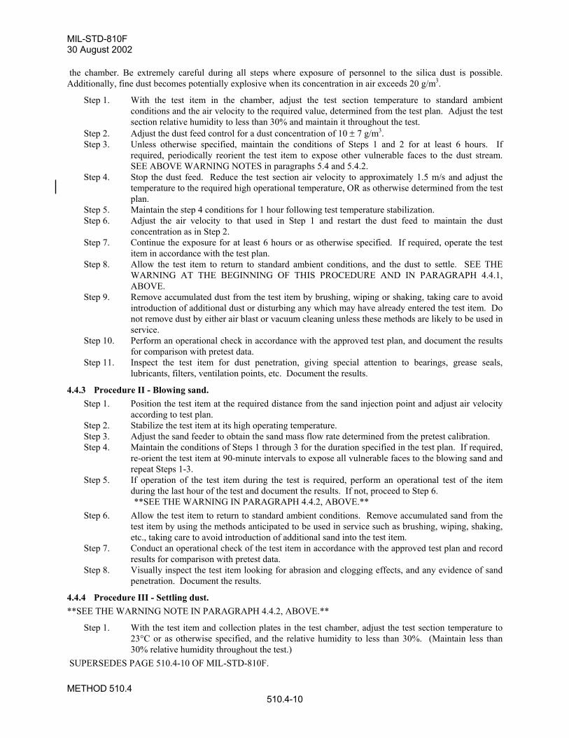
MIL-STD-810F30 August 2002
METHOD 510.4510.4-10
the chamber. Be extremely careful during all steps where exposure of personnel to the silica dust is possible.Additionally, fine dust becomes potentially explosive when its concentration in air exceeds 20 g/m3.
Step 1. With the test item in the chamber, adjust the test section temperature to standard ambientconditions and the air velocity to the required value, determined from the test plan. Adjust the testsection relative humidity to less than 30% and maintain it throughout the test.
Step 2. Adjust the dust feed control for a dust concentration of 10 ± 7 g/m3.Step 3. Unless otherwise specified, maintain the conditions of Steps 1 and 2 for at least 6 hours. If
required, periodically reorient the test item to expose other vulnerable faces to the dust stream.SEE ABOVE WARNING NOTES in paragraphs 5.4 and 5.4.2.
Step 4. Stop the dust feed. Reduce the test section air velocity to approximately 1.5 m/s and adjust thetemperature to the required high operational temperature, OR as otherwise determined from the testplan.
Step 5. Maintain the step 4 conditions for 1 hour following test temperature stabilization.Step 6. Adjust the air velocity to that used in Step 1 and restart the dust feed to maintain the dust
concentration as in Step 2.Step 7. Continue the exposure for at least 6 hours or as otherwise specified. If required, operate the test
item in accordance with the test plan.Step 8. Allow the test item to return to standard ambient conditions, and the dust to settle. SEE THE
WARNING AT THE BEGINNING OF THIS PROCEDURE AND IN PARAGRAPH 4.4.1,ABOVE.
Step 9. Remove accumulated dust from the test item by brushing, wiping or shaking, taking care to avoidintroduction of additional dust or disturbing any which may have already entered the test item. Donot remove dust by either air blast or vacuum cleaning unless these methods are likely to be used inservice.
Step 10. Perform an operational check in accordance with the approved test plan, and document the resultsfor comparison with pretest data.
Step 11. Inspect the test item for dust penetration, giving special attention to bearings, grease seals,lubricants, filters, ventilation points, etc. Document the results.
4.4.3 Procedure II - Blowing sand.Step 1. Position the test item at the required distance from the sand injection point and adjust air velocity
according to test plan.Step 2. Stabilize the test item at its high operating temperature.Step 3. Adjust the sand feeder to obtain the sand mass flow rate determined from the pretest calibration.Step 4. Maintain the conditions of Steps 1 through 3 for the duration specified in the test plan. If required,
re-orient the test item at 90-minute intervals to expose all vulnerable faces to the blowing sand andrepeat Steps 1-3.
Step 5. If operation of the test item during the test is required, perform an operational test of the itemduring the last hour of the test and document the results. If not, proceed to Step 6.**SEE THE WARNING IN PARAGRAPH 4.4.2, ABOVE.**
Step 6. Allow the test item to return to standard ambient conditions. Remove accumulated sand from thetest item by using the methods anticipated to be used in service such as brushing, wiping, shaking,etc., taking care to avoid introduction of additional sand into the test item.
Step 7. Conduct an operational check of the test item in accordance with the approved test plan and recordresults for comparison with pretest data.
Step 8. Visually inspect the test item looking for abrasion and clogging effects, and any evidence of sandpenetration. Document the results.
4.4.4 Procedure III - Settling dust.**SEE THE WARNING NOTE IN PARAGRAPH 4.4.2, ABOVE.**
Step 1. With the test item and collection plates in the test chamber, adjust the test section temperature to23°C or as otherwise specified, and the relative humidity to less than 30%. (Maintain less than30% relative humidity throughout the test.)
SUPERSEDES PAGE 510.4-10 OF MIL-STD-810F.

MIL-STD-810F30 August 2002
METHOD 511.4511.4-1
METHOD 511.4
EXPLOSIVE ATMOSPHERE
NOTE: Tailoring is essential. Select methods, procedures, and parameter levels based on the tailoring processdescribed in Part One, paragraph 4.2.2; and Appendix C. Apply the general guidelines for laboratory test methodsdescribed in Part One, paragraph 5, of this standard.
1. SCOPE
1.1 Purpose. The explosive atmosphere test is performed to:
a. demonstrate the ability of materiel to operate in fuel-air explosive atmospheres without causing ignition, or
b. demonstrate that an explosive or burning reaction occurring within encased equipment will be contained,and will not propagate outside the test item.
1.2 Application. This method applies to all materiel designed for use in or near the vicinity of fuel-air explosive atmospheresassociated with aircraft, automotive, and marine fuels at or above sea level. Procedure II specifically relates toatmospheres in a space in which flammable fluids or vapors exist, or can exist, either continuously or intermittently(e.g., in fuel tanks or within fuel systems). NOTE: Materiel tested to Procedure II is designed such that ignition ofan explosive mixture is contained within the materiel without igniting the surrounding explosive atmosphere; and,during normal operation, or as a result of any fault, the temperature of any external surface will not rise to a levelcapable of causing ignition (including hermetically-sealed materiel). Use other explosive atmosphere safety tests(e.g., electrical or mine safety) if more appropriate.
1.3 Limitations. a. These procedures use an explosive mixture that has a relatively low flash point that may not be
representative of some actual fuel-air or aerosol (such as suspended dust) mixtures.
b. The explosive atmosphere test is a conservative test. If the test item does not ignite the test fuel-airmixture, there is a low probability that the materiel will ignite prevailing fuel vapor mixtures in service. Conversely, the ignition of the test fuel-air mixture by the test item does not mean the materiel will alwaysignite fuel vapors that occur in actual use.
c. These procedures are not appropriate for test altitudes above approximately 16km where the lack ofoxygen inhibits ignition.
d. Because this test is designed for electrical spark ignition, this method is not intended to demonstrateignition due to high surface temperatures.
2. TAILORING GUIDANCE
2.1 Selecting the Explosive Atmosphere Method. After examining requirements documents and applying the tailoring process in Part One of this standard todetermine where explosive atmospheres are foreseen in the life cycle of the test item, use the following to confirmthe need for this method and to place it in sequence with other methods.
2.1.1 Procedure I – Explosive Atmosphere. This procedure is applicable to all types of sealed and unsealed materiel. This test evaluates the ability of the testitem to be operated in a fuel vapor environment without igniting the environment.
SUPERSEDES PAGE 511.4-1 OF NOTICE 1 TO MIL-STD-810F.
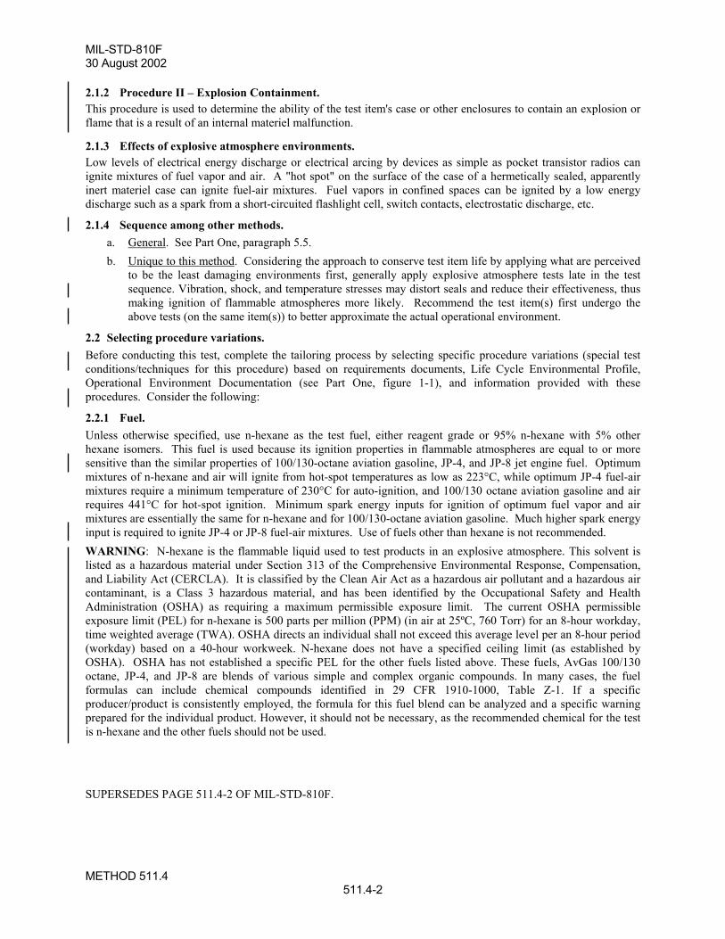
MIL-STD-810F30 August 2002
METHOD 511.4511.4-2
2.1.2 Procedure II – Explosion Containment. This procedure is used to determine the ability of the test item's case or other enclosures to contain an explosion orflame that is a result of an internal materiel malfunction.
2.1.3 Effects of explosive atmosphere environments. Low levels of electrical energy discharge or electrical arcing by devices as simple as pocket transistor radios canignite mixtures of fuel vapor and air. A "hot spot" on the surface of the case of a hermetically sealed, apparentlyinert materiel case can ignite fuel-air mixtures. Fuel vapors in confined spaces can be ignited by a low energydischarge such as a spark from a short-circuited flashlight cell, switch contacts, electrostatic discharge, etc.
2.1.4 Sequence among other methods.a. General. See Part One, paragraph 5.5.b. Unique to this method. Considering the approach to conserve test item life by applying what are perceived
to be the least damaging environments first, generally apply explosive atmosphere tests late in the testsequence. Vibration, shock, and temperature stresses may distort seals and reduce their effectiveness, thusmaking ignition of flammable atmospheres more likely. Recommend the test item(s) first undergo theabove tests (on the same item(s)) to better approximate the actual operational environment.
2.2 Selecting procedure variations. Before conducting this test, complete the tailoring process by selecting specific procedure variations (special testconditions/techniques for this procedure) based on requirements documents, Life Cycle Environmental Profile,Operational Environment Documentation (see Part One, figure 1-1), and information provided with theseprocedures. Consider the following:
2.2.1 Fuel. Unless otherwise specified, use n-hexane as the test fuel, either reagent grade or 95% n-hexane with 5% otherhexane isomers. This fuel is used because its ignition properties in flammable atmospheres are equal to or moresensitive than the similar properties of 100/130-octane aviation gasoline, JP-4, and JP-8 jet engine fuel. Optimummixtures of n-hexane and air will ignite from hot-spot temperatures as low as 223°C, while optimum JP-4 fuel-airmixtures require a minimum temperature of 230°C for auto-ignition, and 100/130 octane aviation gasoline and airrequires 441°C for hot-spot ignition. Minimum spark energy inputs for ignition of optimum fuel vapor and airmixtures are essentially the same for n-hexane and for 100/130-octane aviation gasoline. Much higher spark energyinput is required to ignite JP-4 or JP-8 fuel-air mixtures. Use of fuels other than hexane is not recommended.WARNING: N-hexane is the flammable liquid used to test products in an explosive atmosphere. This solvent islisted as a hazardous material under Section 313 of the Comprehensive Environmental Response, Compensation,and Liability Act (CERCLA). It is classified by the Clean Air Act as a hazardous air pollutant and a hazardous aircontaminant, is a Class 3 hazardous material, and has been identified by the Occupational Safety and HealthAdministration (OSHA) as requiring a maximum permissible exposure limit. The current OSHA permissibleexposure limit (PEL) for n-hexane is 500 parts per million (PPM) (in air at 25ºC, 760 Torr) for an 8-hour workday,time weighted average (TWA). OSHA directs an individual shall not exceed this average level per an 8-hour period(workday) based on a 40-hour workweek. N-hexane does not have a specified ceiling limit (as established byOSHA). OSHA has not established a specific PEL for the other fuels listed above. These fuels, AvGas 100/130octane, JP-4, and JP-8 are blends of various simple and complex organic compounds. In many cases, the fuelformulas can include chemical compounds identified in 29 CFR 1910-1000, Table Z-1. If a specificproducer/product is consistently employed, the formula for this fuel blend can be analyzed and a specific warningprepared for the individual product. However, it should not be necessary, as the recommended chemical for the testis n-hexane and the other fuels should not be used.
SUPERSEDES PAGE 511.4-2 OF MIL-STD-810F.

MIL- STD-810F30 August 2002
METHOD 511.4511.4-3
2.2.2 Fuel-vapor mixture. Use a homogeneous fuel-air mixture in the correct fuel-air ratios for the explosive atmosphere test. Fuel weightcalculated to total 3.8% by volume of the test atmosphere represents 1.8 stoichiometric equivalents of n-hexane inair, giving a mixture needing only minimum energy for ignition. This yields an air/vapor ratio (AVR) of 8.33 byweight (reference f).
a. Required information to calculate fuel weight:(1) Chamber air temperature during the test.(2) Fuel temperature.(3) Specific gravity of n-hexane (see figure 511.4-1).(4) Test altitude: ambient ground or as otherwise identified. (5) Net volume of the test chamber: free volume less test item displacement expressed in liters.
b. Calculation of the volume of liquid n-hexane fuel for each test altitude:(1) In metric units:
Volume of 95% n-hexane (ml) =
( ) ( )( ) ( )( )( )( ) ( )
−
−
hexanenofgravityspecificxKtempchamberpascalspressurechamberxlitersvolchambernet10x27.4 4
(2) In English units:
Volume of 95% n-hexane (ml) =
( ) ( )( ) ( )( )( )( ) ( )
− hexanenofgravityspecificxRtempchamberpsiapressurechamberxftvolchambernet41.150
3
2.2.3 Temperature. Heat the fuel-air mixture to the highest ambient air temperature at which the materiel is required to operate duringdeployment and provide the greatest probability of ignition. Perform all testing at this maximum air temperature.For forced-air-cooled materiel, use a test temperature that is the highest temperature at which the materiel can beoperated and performance evaluated in the absence of cooling air.
2.2.4 Effect of humidity on flammable atmosphere. The effect of humidity upon the fuel-air composition need not be considered in the test if the ambient air dewpointtemperature is 10°C or less because this concentration of water vapor only increases the n-hexane fuel concentrationfrom 3.82% to 3.85% of the test atmosphere. If the atmospheric pressure is cycled from an equivalent of 1525meters above the test level to 1525 meters below, (a 34% change in pressure), the volume of n-hexane will decreasefrom 4.61% to 3.08%. This decrease will compensate for the fuel enrichment effect that results from water vapordilution of the test air supply.
2.2.5 Altitude simulation. The energy required to ignite a fuel-air mixture increases as pressure decreases. Ignition energy does not dropsignificantly for test altitudes below sea level. Therefore, unless otherwise specified, perform all tests with at leasttwo explosive atmosphere steps, one at the highest anticipated operating altitude of the materiel (not to exceed12,200m where the possibility of an explosion begins to dissipate) and one between 78 and 107 kPa (11.3 and15.5 psi) which is representative of most ground ambient pressures. As noted in paragraph 1.3, because of the lackof oxygen at approximately 16 km, do not perform this test at or above this altitude.
SUPERSEDES PAGE 511.4-3 OF MIL-STD-810F.

MIL-STD-810F30 August 2002
METHOD 511.4511.4-4
2.3 Definitions. For the purpose of this method, the following definitions apply:
a. Simulated altitude. Any height that is produced in the test chamber by reducing air pressure.
b. Test altitude. The nominal simulated height(s) (generally, above sea level) at which the test item will betested; i.e., the maximum altitude identified in paragraph 2.2.5.
3. INFORMATION REQUIRED
3.1 Pretest. The following information is required to conduct explosive atmosphere tests adequately.
a. General. Information listed in Part One, paragraphs 5.7 and 5.9; and Appendix A, Task 405, of thisstandard.
b. Specific to this method.
(1) The fuel volume and/or weight.
(2) The quantity of fuel required at each test point.
(3) The off/on cycling rate for the test item.
(4) Any information relative to the location of spark-emitting devices or high temperature components.
3.2 During test. Collect the following information during conduct of the test:
a. General. Information listed in Part One, paragraph 5.10; and in Appendix A, Task 406, of this standard.
b. Specific to this method.
(1) Periods of operation versus test altitude (on/off points).
(2) Quantity of fuel introduced for each test altitude.
3.3 Post-test. a. General. See Part One, paragraph 5.13.
b. Specific to this method.
(1) Chamber test altitude and temperature for each operational check..
(2) Occurrence of any explosion caused by the test item.
(3) Initial analysis of any failures/problems.
4. TEST PROCESS
4.1 Test facility. The required apparatus consists of a chamber together with auxiliary instrumentation capable of establishing,maintaining, and monitoring (see Part One, paragraph 5.18) the specified test conditions. Use a chamber with ameans of determining the explosiveness of a sample of the mixture, such as a spark gap or glow plug ignition sourcewith sufficient energy to ignite a 3.82% hexane mixture. An alternative method of determining the explosivecharacteristics of the vapor is by using a calibrated explosive gas meter that verifies the degree of explosiveness andthe concentration of the fuel-air mixture.
SUPERSEDES PAGE 511.4-4 OF MIL-STD-810F.

MIL- STD-810F30 August 2002
METHOD 511.4511.4-5
4.2 Controls. Before each test, verify the critical parameters. Ensure spark devices function properly and the fuel atomizingsystem is free from deposits that could inhibit its functioning. Adjust the empty test chamber to the highest testaltitude, shut-off the vacuum system, and measure the rate of any air leakage. Verify that any leakage is notsufficient to prevent the test from being performed as required; i.e., introduce the test fuel and wait three minutes forfull vaporization, yet still be at least 1000m above the test altitude.
4.3 Test interruption.a. General. See Part One, paragraph 5.11, of this standard.
b. Specific to this method. If there is an unscheduled undertest interruption, restore the chamber air pressureto ground ambient pressure and purge the chamber to remove the flammable atmosphere. Achieve therequired test altitude, inject the required volume of n-hexane, and reinitiate the test using the same testitem.
4.4 Test Setup. a. General. See Part One, paragraph 5.8.
b. Unique to this method. For test item thermal stabilization measurements for both procedures, installthermocouples on the most massive functional part of the test item, and two thermocouples attached to theinside the of test chamber to detect any temperature increase due to burning of the mixture.
(1) Procedure I.
(a) Install the test item in the test chamber in such a manner that it may be operated and controlledfrom the exterior of the chamber via sealed cable ports. Remove or loosen the external covers ofthe test item to facilitate the penetration of the explosive mixture. Test items requiring connectionbetween two or more units may, because of size limitations, have to be tested independently. Inthis case, extend any interconnections through the cable ports.
(b) Operate the test item to determine correct operation. If possible, identify the location of anysparking or high-temperature components that could cause an explosion.
(c) When necessary, simulate in-service mechanical loads on drive assemblies and servo-mechanicalsystems, and electrical loads on switches and relays; duplicate torque, voltage, current, inductivereactance, etc. In all instances, operate the test item in a manner representative of service use.
(2) Procedure II.
(a) Make provision to circulate the fuel-air mixture into the case being tested. In the case of forced-air-cooled materiel, the cooling air must contain the proper fuel-air mixture. For materiel not usingforced-air cooling, drill and tap the case for insertion of a hose from a blower (to insert the fuel-airmixture), as well as for an outlet hose connection. Take adequate precautions to prevent ignitionof the ambient mixture by backfire or release of pressure through the supply or vent hose. Do notalter the case internal volume by more than ±5% with any modification to facilitate theintroduction of ignitable vapor.
(b) Provide a positive means of igniting the explosive mixture within the case. Drill or tap the case asnecessary for a spark gap, or mount a spark gap internally. Ensure points of ignition are not be morethat 0.5 inch from any vent holes or flame arresting devices; and, unless the design of the materielmakes this impractical, use as many points of ignition as are practical.
(c) To detect explosions within the case, insert a thermocouple into the case and attach it to asensitive galvanometer outside the test chamber.
(d) Ensure the air within the test chamber has a water vapor dew point lower than 10°C (50°F) perparagraph 2.2.4.
SUPERSEDES PAGE 511.4-5 OF MIL-STD-810F.

MIL-STD-810F30 August 2002
METHOD 511.4511.4-6
4.5 Test execution. The following steps, alone or in combination, provide the basis for collecting necessary information concerning themateriel in an explosive atmosphere.
4.5.1 Preparation for test. Before starting the test, review pretest information in the test plan to determine test details (e.g.; procedures, test-item configuration, test temperature, test altitude, etc.).
4.5.2 Procedure I - Operation in an Explosive Atmosphere. Step 1. With the test item installed, seal the chamber and stabilize the test item and chamber inner walls to
within 10°C below the high operating temperature of the test item. Step 2. Adjust the chamber air pressure to simulate the highest operating altitude of the test item (not to
exceed 12,200m) plus 2000m to allow for introducing, vaporizing, and mixing the fuel with the air asdescribed in paragraph 2.2.2.
Step 3. Slowly introduce the required volume of n-hexane into the test chamber as the simulated altitudebegins to drop.
Step 4. Circulate the test atmosphere and continue to reduce the simulated chamber altitude for at least threeminutes to allow for complete vaporization of fuel and the development of a homogeneous mixture.
Step 5. At a pressure equivalent to 1000m above the test altitude, verify the potential explosiveness of thefuel-air vapor by attempting to ignite a sample of the mixture taken from the test chamber using aspark-gap device or glow plug ignition source with sufficient energy to ignite a 3.82% hexanemixture. If ignition does not occur, purge the chamber of the fuel vapor and repeat Steps 1-4. Analternative method of determining the explosive characteristics of the vapor is by using a calibratedexplosive gas meter that verifies the degree of explosiveness and the concentration of the fuel-airmixture.
Step 6. Operate the test item and continue operation from this step until completion of Step 8. Make andbreak electrical contacts as frequently and reasonably possible.
Step 7. To ensure adequate mixing of the fuel and air, slowly decrease the simulated chamber altitude at a rateno faster than 100 meters per minute by bleeding air into the chamber.
Step 8. Stop decreasing the altitude at 1000m below the test altitude, perform one last operational check, andswitch-off power to the test item.
Step 9. Verify the potential explosiveness of the air-vapor mixture as in Step 5, above. If ignition does notoccur, purge the chamber of the fuel vapor, and repeat the test from Step 1.
Step 10. Adjust the simulated chamber altitude to the equivalent of 2000m above site pressure. Step 11. Repeat Steps 3-7. At site pressure, perform one last operational check and switch-off power to the
test item. Step 12. Verify the potential explosiveness of the air-vapor mixture as in Step 5, above. If ignition does not
occur, purge the chamber of the fuel vapor, and repeat the test from Step 10. Step 13. Document the test results.
4.5.3 Procedure II – Explosion Containment. Step 1. Place the test item or a model of the test item of the same volume and configuration within the case,
and install the case in the explosion chamber. Step 2. Ensure that the air within the test chamber has a water vapor dew point lower than 10°C (50°F) per
paragraph 2.2.4. Step 3. Seal the chamber with the test item inside, and raise the ambient air temperature inside the chamber to
high operating temperature of the test item.
SUPERSEDES PAGE 511.4-6 OF MIL-STD-810F.