Embed Size (px)
Citation preview

38 Circuit block spacer for calendar 4408 538
39 Date driving wheel for ten's digit 0802 506
40 Pinion for ten's digit 1013 504 41 3rd intermediate wheel
for calendar corrector 0962 501
42 4th intermediate wheel for calendar corrector 0962 502 43 3rd intermediate wheel
for calendar 0817 51444 Hour wheel
0271 564
45 Circuit block for calendar 4000 595
46 B connector 4313 58247 A connector
4313 581
48 Ratchet lever 0981 50049 Control jumper
1024 502
50 2nd intermediate wheel for calendar corrector 0962 559
51 Contact point spring 4281 510
- 9 -

Circuit block cover A screw 0012 354
Circuit block cover A 4457 965 (for cal.7D48A)
Circuit block cover D 4457 774
Circuit block cover C screw 0012 354
Circuit block cover C 4457 966
Oscillating weight bridge 0198 503
Intermediate wheel for generating rotor 1002 505
Circuit block 4000 594
52
53
54
55
56
57
58
59
-10 -
4457 979 (for cal.7D46A)

60 Insulator for circuit block 4216 538
61 Generating coil block 4002 525
62 Second coil block 4002 524
63 Hour and minute coil block 4002 530
64 Train wheel bridge screw 0012 354
65 Train wheel bridge 0125 556
66 Second wheel & pinion 0240 506
67 Intermediate second wheel 0317 55768 4th wheel & pinion
0241 566 69 3rd wheel & pinion 0231 55670 Generating rotor
4146 522
71 Second rotor 4146 521
72 Hour and minute rotor 4146 523
73 Setting wheel 0281 55274 Intermediate minute wheel
0766 553 75 Minute wheel & pinion 0261 55376 Spacer for center wheel
& pinion 4283 557 77 Setting lever spring screw
0012 35478 Setting lever spring
0388 558
79 Setting lever 0383 557
- 11 -

Yoke 0384 557
Train wheel setting lever 0391 557
Center wheel & pinion 0221 712
83 Winding stem (0351 510) Clutch wheel
0282 523
85 1st intermediate wheel for calendar corrector 0962 557
Rechargeable battery connection(+) 4271 522
87 Generating stator 4239 527
80
81
82
84
86
88 Second stator 4239 523
89 Hour and minute stator 4239 522
90 Lead pin for RZ1 0027 369
91 Main plate 0100 710
- 12 -

PARTS CATALOGUE CAL.7D46A/7D48A
<7D48A>⑧ Indication disc for year ⑩ Date dial for ten's digit ⑪ Date dial for units digit
Date dial forunit digit
Date dial forten's digit
Indicationdisc for year
Color offigure
Color ofbackground
Font type
0878A85 0878A84 1023560 BLACK WHITE Italic
0878A91 0879A90 1023561 BLACK WHITE Gothic
0878B06 0878B05 1023563 WHITE BLACK Gothic
<7D46A>⑩ Date dial for ten's digit ⑪ Date dial for units digit
Date dial forunit digit
Date dial forten's digit
Color offigure
Color ofbackground
0878B06 0878B05 WHITE BLACK
0878A91 0878A90 BLACK WHITE
84 Winding Stem 0351510
The above parts are determined based on the case designe.Refer to Parts Catalogue Web site to choose a corresponding part.
13
Remarks

TECHNICAL GUIDE Cal.7D46A/7D48A
● The explanation here is only for the particular points of Cal. 7D48A. ● For the repairing, checking and measuring procedures, refer to the “TECHNICAL
GUIDE, GENERAL INSTRUCTIONS”.
I. STRUCTURE OF THE CIRCUIT BLOCK 59 Circuit block 45 Circuit block for calendar
II. REMARKS ON DISASSEMBLING AND REASSEMBLING 1. About “exclusive jig pin” used for assembly Cal. 7D** employs a new structure for the calendar unit; therefore, it is necessary to set each gearwheel correctly when assembling. Consequently, two kinds of “exclusive jig pins” are available in consideration of efficiency in assembly performance. Be sure to use these “exclusive jig pins” for assembly of the calendar unit. * Be careful not to forget to remove and not to lose the “exclusive jig pin” when assembling is completed. <How to use the exclusive jig pins> “Positioning pin for the spring for intermediate wheel for month indicator”
In assembly, set the “positioning pin for the spring for intermediate wheel for month indicator” after assembling the (38) jumper for ten’s digit, and remove it after assembling from the (37) spring for intermediate wheel for month indicator to the (15) train wheel bridge for calendar screws. “Supporting pin for alignment”
In assembly, set the “supporting pin for alignment” after assembling the (28) screw for the piezoelectric motor cover, and remove it after assembling from the (27) control wheel to the (15) train wheel bridge for calendar screws. 2. Precautions for jumpers on calendar unit when assembling and disassembling Target parts:
(35) Jumper for month, (36) Spring for intermediate wheel for month indicator (37) Jumper for ten’s digit, (12) Jumper for units digit, (13) Jumper for year
● Precautions for disassembly and assembly For disassembly: When individually disassembling the above parts, remove them with sufficient care since they are used at the points of engagement. Additionally, they can be disassembled even in a state attached to the circuit block spacer for calendar without
14
individual disassembling.

TECHNICAL GUIDE Cal.7D46A/7D48A
For assembly: Check the points of engagement for rattle when assembling. If they rattle, replace the circuit block spacer for the calendar.
3. How to install the hands Cal. 7D** features the perpetual calendar. Thus, the hands should be carefully mounted exactly as instructed below. 1. Pull out the winding stem to the first click position, and set the calendar to “the leap
year, January 1” year 年
date
month
2. Pull out the winding stem to the second click position, and turn the crown to set the
24H contact point as illustrated below. (To correct the timing of date change)
*Connect the probes of testers to “A” and “B” portions. The 24H contact point will be adjusted, allowing for a check of date changing status.
3. Keep the watch in this state when carrying of the 24-hour hand, month indicator, hour
* When removing the hands during repair wor
B ortion
A portion Date changing status
15
If the hands are re individual disassembling. “the leap year, January 1”, the correct position o
p
out the installation of the hands in order hand, minute hand and second hand.
k, ensure that the calendar is set to “the
“A” por t ion in the illustration to the left
moved with the calendar set to a date other than f the year may be lost.

TECHNICAL GUIDE Cal.7D46A/7D48A
16
- - - - 10 - - - - -- - - - - 20 - - - - -- - - - - 30 - - - - -- - - -
Checking for leakage between coil for driving hands and coil for detecting generation ●●●● How to check the leakage 1. Make the tester ready for measuring the resistance. 2. Apply the probes of the tester to 1 “A” and “a”, 2 “A” and “b”, 3 “B” and “a”, and 4 “B” and
“b”, respectively, to measure the resistance. 3. If the four measurements obtained are all infinitely great, that is, if the resistance was
unable to be measured for all the four cases, there is no leakage between coil for driving hands and coil for detecting generation. As a guideline, there is a leakage if measurements of less than 2 kΩwere obtained.
III. VALUE CHECKING AND ADJUSTMENT ●●●●Coil block resistance
Second coil block: 2.00kΩ -– 2.45kΩ Hour and minute coil block:
Coil for driving hands: 1.00 kΩ -– 1.25 kΩ Coil for detecting rotation of the rotor: 270 Ω-– 330 Ω
Generating coil block: 360Ω -– 420Ω Note: Measure the coil block resistance after installing each coil block to the movement, checking that stable measurements are obtained. *The motor driving the hour and minute hands uses a special driving system so that they move quickly to indicate the current time immediately after the time relay function is activated. The hour and minute coil block has two layers of coils, one for driving the hands and the other for detecting rotation of the rotor, and it is necessary to measure the resistance of each coil layer. ・The illustration below shows the patterns to which the probes of the tester should be applied to measure the resistance of the respective coils.
●●●●Checking for leakage between coil for driving hands and coil for detecting rotation of the rotor *If the hour and minute hands do not move properly when the time relay function is activated, that is, if they remain stopped or will not move smoothly, check for leakage between coil for driving hands and coil for detecting rotation of the rotor. This checking is required only if such a problem is found. If leakage is detected, replace the hour and minute coil block with a new one. ●●●● How to check the leakage 1. Make the tester ready for measuring the resistance. 2. Apply the probes of the tester to 1 “A” and “a”, 2 “A” and “b”, 3 “B” and “a”, and 4 “B”
and “b”, respectively, to measure the resistance. 3. If the four measurements obtained are all infinitely great, that is, if the resistance is
unable to be measured for all the four cases, there is no leakage between coil for driving hands and coil for detecting rotation of the rotor. As a guideline, there is leakage if measurements of less than 2 kΩare obtained.
● Generating coil block resistance 340Ω - 440Ω Note: Measure the generating coil block resistance after installing it to the movement, checking that stable measurements are obtained.
A
B
a
b
Pattern for checking the coil for driving hands
Pattern for checking the coil for detecting rotation of the rotor
Revision: Aug. 2008

TECHNICAL GUIDE Cal.7D46A/7D48A
- - -- - - - - 10 - - - - -- - - - - 20 - - - - -- - - - - 30 - - - - -- - - - -
●●●●Current consumption For the whole movement (while the hands are moving): Less than 0.70μA (with 1.55 V supplied from a battery) For the circuit block alone: Less than 0.40μA (with 1.55 V supplied from a battery) ●●●●How to measure the current consumption for the whole movement (while the hands are moving) 1. Disassemble unnecessary parts to make the movement ready for the measurement.
Follow the disassembling procedure illustrated in this manual until you remove the rechargeable battery unit, and then, reassemble the oscillating weight. As a result, the rechargeable battery unit, insulator for rechargeable battery and rechargeable battery clamp are removed from the movement.
2. Apply the minus terminal to “a” portion in the illustration and plus terminal to the circuit block cover A, respectively.
3. For a few seconds after the probes of the tester are appliedin the quick start mode, and current consumption cannot bswitch the IC from the quick start to the normal hand moscillating weight from side to side continuously for more ttester connected to the movement. (The IC will detect thwill be switched to the normal hand movement mode.)
Note When moving the oscillating weight from side to side, take carethe tester touches the oscillating weight.
4. After checking that the IC has been switched to the normal
a stable measurement can be obtained, read the measurem(If the measurement value remains high or unstable, repeat
Notes: * Light may increase the current consumption, resulting in an inthe current consumption exceeds the standard value, protect the black cloth or the like after following step “3” above, and make a m* When the current consumption for the whole movement exceedthe current consumption for the circuit block alone is within thdriving pulse may be generated to compensate for the heavy loaetc. In that case, overhaul and clean the movement parts, andconsumption for the whole movement again.
a +
_
17
Circuit block cover A
to the movement, the IC is e measured properly. To ovement mode, move the
han three seconds with the e electricity generation and
lest the minus terminal of
Oscillating weight
hand movement mode and ent. step “3” above.)
accurate measurement. If movement from light with a
easurement again. s the standard value while
e standard value range, a d applied on the gear train, then, measure the current

TECHNICAL GUIDE Cal.7D46A/7D48A
18
-
- - - -- - - - - 10 - - - - -- - - - - 20 - - - - -- - - - - 30 - - - - -- - - - - 40 -
●●●● How to measure the current consumption for the circuit block alone 1. Connect the tester to the circuit block as shown in the illustration.
2. Checking that a stable measurement is obtained, read the current consumption. (If the measurement value remains high or unstable, repeat step “2” above.)
Notes: * The current consumption measurement for the circuit block alone is particularly susceptible to light, and a value higher than the actual measurement may be obtained if the circuit block is exposed to light. Protect the circuit from light with a black cloth or the like after following step “2” above, and then, measure the current consumption. * If the current consumption for the circuit block alone exceeds the standard value, the duration of the charge will be shorter than specified. In that case, replace the circuit block with a new one. ●●●● Checking the automatic generating system
1. Apply the probes of the tester as shown in the illustration, and measure the voltage of the rechargeable battery. (The obtained voltage is called the “initial voltage”.)
Notes: When applying the minus probe of the
tester to the rechargeable battery, take care not to short-circuit the lead terminal (-) and the rechargeable battery clamp. If a short-circuit has occurred, leave the
watch untouched for more than ten minutes, and measure the voltage again, checking that a stable measurement is obtained.
2. Close the case back tentatively, and swing the watch from side to side 200 times at a rate of 2 to 3 swings a second, making an arc of approximately 20 cm.
+
_

TECHNICAL GUIDE Cal.7D46A/7D48A
19
- -- - - - - 10 - - - - -- - - - - 20 - - - - -- - - - - 30 - - - - -- - - - - 40 - - - - --
(Caution)
3. Within 3 minutes after swinging the watch, measure the voltage of the rechargeable battery in the same manner as in step “1” above.
4. Refer to the table below, and decide whether the automatic generating system is normal or defective.
[Initial voltage and guidelines of normal/defective decision]
Initial voltage Guidelines of normal/defective decision 0.45~~~~1.0 V After charging, the voltage of rechargeable battery has
increased 0.1 V or more from the initial voltage. 1.01~~~~1.2V After charging, the voltage of rechargeable battery has
increased 0.05 V or more from the initial voltage. * The guidelines specified in the above table apply only when the initial voltage is within the
range between 0.45 V and 1.2 V. * The amount of electricity generated by swinging the watch varies depending on the
manner in which you swing it, such as the rate of swinging and the size of the swinging arc. Please note, therefore, that checking through the procedure above provides only a guideline for normal/defective decision.
<<<<For your information> 1. Number of swings and power reserve When the power reserve inn the rechargeable battery is depleted and the watch stops
completely, swinging it approximately 500 times at a rate of 2 to 3 times a second will start the second hand moving at normal one-second intervals in stead of two-second intervals. If the second hand still moves at two-second intervals after 500 swings, swing the watch further until it moves at one-second intervals.
While the second hand is moving at one-second intervals, swing the watch further until it moves at one-second intervals.
2. The number of days over which the watch is worn and power reserve Wearing the watch continuously for 12 hours will accumulate approximately one and a
half additional days of power reserve. (Example) If you wear the watch every day for 12 hours over a period of a week, approximately 10 days of power reserve will be secured in the rechargeable battery. While the power saving function is in operation and the hands are stopped, this amount of power reserve will keep the watch operating for approximately 2 months.
● Inspection of perpetual calendar and PTP operation in move state Cal. 7D48A is equipped with a perpetual calendar which automatically advances the calendar up to February 28, 2100. Here, an inspection is carried out if the “perpetual calendar” operates normally. Note: This inspection cannot be made when the watch is stopped. If the watch to be inspected has stopped, start the inspection after the second hand starts moving at 1-second interval by manually charging it and the amount of stored electrical energy reaches above 1.3v. ・・・・ Inspection method of PTP operation in move state 1. Recharge the rechargeable battery until the amount of stored electrical energy reaches above 1.3v. 2. After tightening the (28) screw for the piezoelectric motor cover, pull out the crown from the “0” position to the first click position and leave it as it is for two seconds or longer. Then, “Pull the crown out and push it back in the order of the “0” position, first click position, “0” position, first click position and “0” position, and return it to the normal position.” Carry out this operation within one second. 3. Check that the (32) piezoelectric rotor rotates smoothly. (Normal operation) If it rotates smoothly, PTP operation is normal. 4. If it does not rotate smoothly, carry out the procedures from 1, and if it still does not rotate, overhaul the calendar assembly part.
ut th is check con t inuously, carry out re-checks at an interval of one minute or
longer. Note that this is structured not to be electrically checked continuously. ・・・・ Inspection method of perpetual calendar
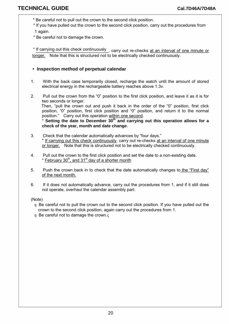
1. With the back case temporarily closed, recharge the watch until the amount of stored electrical energy in the rechargeable battery reaches above 1.3v.
2. Pull out the crown from the “0” position to the first click position, and leave it as it is for
two seconds or longer. Then, “pull the crown out and push it back in the order of the “0” position, first click
position, “0” position, first click position and “0” position, and return it to the normal position.” Carry out this operation within one second. * Setting the date to December 30th and carrying out this operation allows for a check of the year, month and date change.
3. Check that the calendar automatically advances by “four days.” * If carrying out this check continuously, carry out re-checks at an interval of one minute or longer. Note that this is structured not to be electrically checked continuously.
4. Pull out the crown to the first click position and set the date to a non-existing date. * February 30th, and 31st day of a shorter month
5. Push the crown back in to check that the date automatically changes to the “First day” of the next month.
6. If it does not automatically advance, carry out the procedures from 1, and if it still does
not operate, overhaul the calendar assembly part. (Note) ・ Be careful not to pull the crown out to the second click position. If you have pulled out the
crown to the second click position, again carry out the procedures from 1. ・ Be careful not to damage the crown.
* Be careful not to pull out the crown to the second click position. * If you have pulled out the crown to the second click position, carry out the procedures from 1 again. * Be careful not to damage the crown.
* If carrying out this check continuously
20
TECHNICAL GUIDE Cal.7D46A/7D48A

TECHNICAL GUIDE Cal.7D46A/7D48A
21
IV. TROUBLE SHOOTING GUIDE ● The following are the tips on repairing Cal. 7D46A, 7D48A, which you will find helpful in working on 1. Summary of important functions characteristic of Cal. 7D46A, 7D48A 1) The power save function is activated after the watch is left untouched for approximately 24 hours. 2) The manual power save function is activated by pulling out the crown to the first click and pushing it
in to the normal position within one second. 3) While the second hand is moving at two-second intervals, the power save function cannot be
activated either automatically or manually. 4) If the crown is pulled out to the second click while the power save function is in operation, the time
computed by the built-in IC will be canceled, thus disabling the time relay function. 5) The accuracy of the time computed by the built-in IC while the power save function is in operation is
equivalent to that of conventional quartz watches. If the power save function has been active for a long term before the time relay function is activated, the time indicated by the hands may include a certain amount of time loss or gain that has accumulated during that time.
6) If the power reserve is depleted while the power save function is in operation, the time relay function may not be activated by swinging the watch. Instead, the second hand starts moving at two-second intervals.
the watch.

TECHNICAL GUIDE Cal.7D46A/7D48A
22
Problems, causes and methods of repair Problems Possible causes Methods of repair and checking
The quickness of the hand movement after the activation of the time relay function has reduced a little.
1) The coil for detecting generation of the hour and minute coil block is broken.
1) Check the resistance of the coil for detecting generation. Replace the hour and minute coil block if the coil is broken.
The oscillating weight rotates at an abnormally high rate, and no charging is made.
1) The coil of the generating coil block is broken. 2) The pivot of the generating rotor is broken. (The pinion of the generating rotor and the gear of the intermediate wheel for generating rotor are out of mesh.)
1) Check the resistance of the generating coil block. Replace the generating coil block if the coil is broken. 2) Remove the broken piece of the generating rotor, and replace and lubricate the generating rotor. (Overhaul and clean if necessary.)
The oscillating weight will not rotate.
1) The gear of the oscillating weight and the pinion of the intermediate wheel for generating rotor are out of mesh. 2) The pivot of the generating rotor is broken. (The pinion of the generating rotor and the gear of the intermediate wheel for generating rotor engage with each other.)
1) If the gear of the oscillating weight and the pinion of the intermediate wheel for generating rotor are intact, reassemble them to the movement. 2) Remove the broken piece of the generating rotor, and replace and lubricate the generating rotor. (Overhaul and clean if necessary.)
The current consumption for the whole movement exceeds the standard value.
1) When the measurement is made, the IC is still in the quick start mode. (When the current consumption measures about 200μA, it is likely that the IC is in the quick start mode.) 2) The load applied on the gear train, etc. has increased, and the driving pulse to compensate it has been generated.
1) After connecting the tester, move the oscillating weight more quickly for a longer period of time, and then, make the measurement again. 2) If the current consumption for the circuit block alone is within the standard value range, overhaul and clean the movement parts, and then, make the measurement again.
The current consumption for the circuit block alone exceeds the standard value.
1) The light from outside the movement is affecting the measurement. 2) When the measurement is made, the IC is still in the quick start mode. (When the current
1) Shut out the light, and make the measurement again. 2) Switch the IC to the normal mode, and make the measurement again.

TECHNICAL GUIDE Cal.7D46A/7D48A
23
consumption measures about 200μA, it is likely that the IC is in the quick start mode.) 3) The IC is out of order.
3) Replace the circuit block.
Swinging the watch while the power save function is active will not activate the time relay function. (Swinging the watch starts the second hand moving at two-second intervals.)
The energy stored in the rechargeable battery has been depleted while the power save function is in operation.
Swing the watch until the second hand moves at one-second intervals, and activate the power save function manually to check if the time relay function can be activated.
Swinging the watch while the power save function is active will not activate the time relay function. (Swinging the watch will not start the second hand moving at all.)
There is electric leakage inside the hour and minute coil block.
Check for leakage of the hour and minute coil block. Replace the part if leakage is detected.
After the time relay function is activated, the hands do not make the quick movement smoothly, or the hands indicate a time that differs greatly from the correct time.
There is electric leakage inside the hour and minute coil block.
Check for leakage of the hour and minute coil block. Replace the part if leakage is detected.
*For troubleshooting of defects that conventional quartz watches have in common, refer to the “TECHNICAL GUIDE, GENERAL INSTRUCTIONS”.


![[0962-000058][Proposal Submission][Powerpoint …...Microsoft PowerPoint - [0962-000058][Proposal Submission][Powerpoint Upload][Upl-001][NAGAP Conference 2018_CitadelFINAL.pptx] …](https://img.pdfslide.us/doc/110x75/5ecf9d9ba55e956afb29d094/0962-000058proposal-submissionpowerpoint-microsoft-powerpoint-0962-000058proposal.jpg)