Embed Size (px)
Citation preview

20150924 d1
43rd Asia Expert Meeting on UN Regulations related to
External Projections of Passenger Cars (R26),Child Restraint System (R44) &
Speed Limitation Devices (R89)
Date : October 5th and 6th , 2015 Place : For October 5th Meeting Room, Level 4, Automotive Engineering Division, Road Transport Department (JPJ), Putrajaya For October 6th JPJ Conference Room, (Al-Khawarizmi Meeting Room) IT Division - JPJ, Cyberjaya
Day 1:
9:30 – 12:00 Testing Procedures and Discussion on Checklist : UNR26, UNR44 and UNR89
10:30 - 10:45 Coffee Break (15 minutes)
Additional Agenda : If necessary, other outstanding issues (next WG, next WS, two Japan trainings, P/P forum
etc.) to be discussed after morning session.
Day 2:
8:30 - 9:30 Registration
9:30 - 9:40 Opening Address : from JPJ
9:40 – 9:45 Message : from JASIC
9:45 - 11:00 UN R26 - General Information and Technical Requirements : from Mr. Kikuchi
Q & A & Discussion
11:00 – 11:15 Photo Session and Break
11:15 - 13:00 UN R44 - General Information and Technical Requirements : from Mr. Takagi
Q & A & Discussion
13:00 – 14:00 Lunch
14:00 – 16:00 UN R89 - General Information and Technical Requirements: from Mr. Yonezawa
Q & A & Discussion
16:00 - 16:10 Closing

UN Regulation No. 26(EXTERNAL PROJECTIONS)
Technical Requirements
October 5, 2015Sho Kikuchi
PASSIVE SAFETY SUBCOMMITTEE in JASICJapan Automobile Standards Internationalization Center

Contents
1. Scope and Purpose
2. Test and Measurement Main Instrument
3. Test Items

Contents
1. Scope and Purpose
2. Test and Measurement Main Instrument
3. Test Items

1. Scope and Purpose
*1 Notes: For rear-view mirror, refer to requirements in the UN R46
ScopeThis Regulation applies to external projections of category M1 vehicles. It does not apply to exterior rear-view mirrors*1 or to the ball of towing devices.
Purpose
The purpose of this Regulation is to reduce the risk or seriousness of bodily injury to a person hit by the bodywork or brushing against it in the event of a collision. This is valid both when the vehicle is stationary and in motion.
Applicationfor approval
The application for approval of a vehicle type with regard to its external projections shall be submitted by the vehicle manufacturer or by his duly accredited representative.
ApprovalIf the vehicle type submitted for approval pursuant to this Regulation meets the requirements of paragraphs 5. and 6. below, approval of that vehicle type shall be granted.
UN R46 INDIRECT VISION:When the mirror is mounted on a plane surface, all parts, irrespective of the adjustment position of the device, including those parts remaining attached to the support after the test provided for in paragraph 6.1.3.2. below, which are in potential, static contact with a sphere either 165 mm in diameter in the case of an interior mirror or 100 mm in diameter in the case of an exterior mirror, shall have a radius of curvature 'c' of not less than 2.5 mm.
1

Contents
1. Scope and Purpose
2. Test and Measurement Main Instrument
3. Test Items

2. Test and Measurement Main Instrument
Cone with a half angle of 30deg. Sphere of 100mm diameter Sphere of 165mm diameter
Radius gauge Scale Plumb bob
Push-pull gauge Durometer Colored chalk
2

Contents
1. Scope and Purpose
2. Test and Measurement Main Instrument
3. Test Items

5 General specifications
6 Particular specifications
6.1 Ornaments
6.2 Headlights
6.3 Grilles and gaps
6.4 Windscreen wipers
6.5 Bumpers
6.6 Handles, hinges and push-buttons of doors, luggage compartments and bonnets;fuel tank filler caps and covers
6.7 Wheels, wheel nuts, hub caps and wheel discs
6.8 Sheet-metal edges
6.9 Body-panels
6.10 Lateral air or rain deflectors
6.11 Jacking brackets and exhaust pipes
6.12 Air intake and outlet flaps
6.13 Roof
6.14 Windows
6.15 Registration plate brackets
6.16 Luggage racks and ski racks
6.17 Aerials
3. Test Items
3

5 General specifications
6 Particular specifications
6.1 Ornaments
6.2 Headlights
6.3 Grilles and gaps
6.4 Windscreen wipers
6.5 Bumpers
6.6 Handles, hinges and push-buttons of doors, luggage compartments and bonnets;fuel tank filler caps and covers
6.7 Wheels, wheel nuts, hub caps and wheel discs
6.8 Sheet-metal edges
6.9 Body-panels
6.10 Lateral air or rain deflectors
6.11 Jacking brackets and exhaust pipes
6.12 Air intake and outlet flaps
6.13 Roof
6.14 Windows
6.15 Registration plate brackets
6.16 Luggage racks and ski racks
6.17 Aerials
3. Test Items

Conditions The vehicle in the laden condition, with all doors, windows and access lids etc., in the closed position
Scope
The external surface of vehicles;• At a height of 2m or less• Above the floor line• Located can be contacted by a sphere 100mm in diameter
in their static condition as well as when in operation
Requirements
• shall not exhibit, directed outwards
- any pointed- sharp parts- any projections of such shape, dimensions, direction or hardness as to be
likely to increase the risk or seriousness of bodily injury to a person hit by the external surface or brushing against it in the event of a collision
- any part likely to catch on pedestrians, cyclists or motor cyclists
• shall have a radius of curvature more than 2.5mm
This requirement shall not apply to parts of the external surface;‐ which protrude less than 5mm
*but the outward facing angles of such parts shall be blunted,save where such parts protrude less than 1.5mm
‐ Protruding parts of the external surface, made of a material of hardness not exceeding 60 shore A
5. General specifications
Outline
4

5. General specifications
"Laden vehicle" means the vehicle laden to the maximum permitted technical mass.
2.0mLaden vehicle
Floor line
This area is the scope of application for the General specifications.
Contacted lines arethe scope of applicationfor the General specifications.
Bonnet hood
No contacted area isout of the scope of applicationfor the General specifications.
Conditions and Scope
5
Grille
Sphere of100mm diameter

Floor line:Successively position round a laden vehicle a cone with a vertical axis the height of which is not defined, and with a half angle of 30deg. in such a way that it contacts, constantly and as low as possible, the external surface of the vehicle.The floor line is the geometric trace of these points of contact.
The jacking points, exhaust pipes or wheels shall not be taken into consideration.
5. General specifications
Jacking point Exhaust pipe
Marking
Cone with a half angle of 30deg.
Floor line
Conditions and Scope
6

Durometer
Radius gauge
5. General specifications
Scene of a test
radius of curvaturemore than 2.5mm
Clearance
This test is checking whether the external surface of vehicles have a radius of curvature more than 2.5mm.
The durometer is used to measured the hardness for protruding parts of the external surface.
The provisions of the General specifications shall apply in additionto the Particular, except where these Particular specifications expressly provide otherwise.
7

5 General specifications
6 Particular specifications
6.1 Ornaments
6.2 Headlights
6.3 Grilles and gaps
6.4 Windscreen wipers
6.5 Bumpers
6.6 Handles, hinges and push-buttons of doors, luggage compartments and bonnets;fuel tank filler caps and covers
6.7 Wheels, wheel nuts, hub caps and wheel discs
6.8 Sheet-metal edges
6.9 Body-panels
6.10 Lateral air or rain deflectors
6.11 Jacking brackets and exhaust pipes
6.12 Air intake and outlet flaps
6.13 Roof
6.14 Windows
6.15 Registration plate brackets
6.16 Luggage racks and ski racks
6.17 Aerials
3. Test Items

6.1 Ornaments
Conditions To apply the 10 daN force a flat-ended ram of not more than 50 mm diameter shall be used.
Scope These provisions shall not apply to ornaments on radiator grilles.
Requirements
• Added ornaments which project more than 10 mm from their support shall retract, become detached or bend over under a force of 10 daN exerted at their most salient point in any direction in a plane approximately parallel to the surface on which they are mounted.
• After the ornaments are retracted, detached or bent over, the remaining projections shall not project more than 10 mm.
Outline
Push-pull gauge
The push-pull gauge is used to apply a force of 10 daN to the Ornament
8

5 General specifications
6 Particular specifications
6.1 Ornaments
6.2 Headlights
6.3 Grilles and gaps
6.4 Windscreen wipers
6.5 Bumpers
6.6 Handles, hinges and push-buttons of doors, luggage compartments and bonnets;fuel tank filler caps and covers
6.7 Wheels, wheel nuts, hub caps and wheel discs
6.8 Sheet-metal edges
6.9 Body-panels
6.10 Lateral air or rain deflectors
6.11 Jacking brackets and exhaust pipes
6.12 Air intake and outlet flaps
6.13 Roof
6.14 Windows
6.15 Registration plate brackets
6.16 Luggage racks and ski racks
6.17 Aerials
3. Test Items

6.2 Headlights
Headlight
=> 30mm or more
Conditions Case of Retracting headlights;shall meet the above requirement in both the operative and retracted positions.
Scope do not apply to headlamps which are sunk into the bodywork or which are "overhung" by the bodywork.
Requirements
• Projecting visors and rims that as measured in relation to the external transparent surface of the headlight does not exceed 30 mm and their radius of curvature is at least 2.5 mm throughout.
• After the ornaments are retracted, detached or bent over, the remaining projections shall not project more than 10 mm.
Outline
9

5 General specifications
6 Particular specifications
6.1 Ornaments
6.2 Headlights
6.3 Grilles and gaps
6.4 Windscreen wipers
6.5 Bumpers
6.6 Handles, hinges and push-buttons of doors, luggage compartments and bonnets;fuel tank filler caps and covers
6.7 Wheels, wheel nuts, hub caps and wheel discs
6.8 Sheet-metal edges
6.9 Body-panels
6.10 Lateral air or rain deflectors
6.11 Jacking brackets and exhaust pipes
6.12 Air intake and outlet flaps
6.13 Roof
6.14 Windows
6.15 Registration plate brackets
6.16 Luggage racks and ski racks
6.17 Aerials
3. Test Items

6.3 Grilles and gaps
Scope
The requirements of the General specifications shall not apply to gaps between fixed or movable elements, provided that the distance between consecutive elements does not exceed 40 mm and provided that the grilles and gaps have a functional purpose.
Requirements
• Gaps exceed 40 mm
- The radius of curvature shall be 2.5 mm or more.
• Gaps between 40 mm and 25 mm
- The radius of curvature shall be 1 mm or more.
• Gaps between two consecutive elements is equal to or less than 25 mm
- The radius of curvature of external faces of the elements shall not be less than 0.5 mm
• The junction of the front with the side faces of each element forming a grille or gap shall be blunted.
Outline
10

In case where Gaps exceed 40 mm, general specifications is applied.
For Fig. on the right, the surface shall have shall have a radius of curvature more than 2.5mm.
Scene of a testGrilles:
6.3 Grilles and gaps
The distance between two points in contact with a sphere 100 mm diameter is measured.
11

5 General specifications
6 Particular specifications
6.1 Ornaments
6.2 Headlights
6.3 Grilles and gaps
6.4 Windscreen wipers
6.5 Bumpers
6.6 Handles, hinges and push-buttons of doors, luggage compartments and bonnets;fuel tank filler caps and covers
6.7 Wheels, wheel nuts, hub caps and wheel discs
6.8 Sheet-metal edges
6.9 Body-panels
6.10 Lateral air or rain deflectors
6.11 Jacking brackets and exhaust pipes
6.12 Air intake and outlet flaps
6.13 Roof
6.14 Windows
6.15 Registration plate brackets
6.16 Luggage racks and ski racks
6.17 Aerials
3. Test Items

6.4 Windscreen wipers
Scope
• The windscreen wiper, rear window wipers and headlamp wipers fittings.• General specifications shall not apply to the wiper blades or to any supporting
members.However, these units shall be so made as to have no sharp angles or pointed or cutting parts.
Requirements
• shall be such that the wiper shaft is furnished:
- with a protective casing which has a radius of curvature meeting the requirements of paragraph 5.4. above
- an end surface area of not less than 150mm2.
• In the case of rounded covers;
- with a protective casing which has a radius of curvature meeting the requirements of paragraph 5.4. above
- these shall have a minimum projected area of 150mm2 when measured not more than 6.5 mm from the point projecting furthest.
Outline
12

6.4 Windscreen wipers
150mm2 or more
Rounded covers:have a minimum projected area of 150mm2 when measured not more than 6.5 mm from the point projecting furthest
Section BB TOP VIEW
150mm2 or more
Protective casing:an end surface area of not less than 150mm2
TOP VIEW
Details
13

5 General specifications
6 Particular specifications
6.1 Ornaments
6.2 Headlights
6.3 Grilles and gaps
6.4 Windscreen wipers
6.5 Bumpers
6.6 Handles, hinges and push-buttons of doors, luggage compartments and bonnets;fuel tank filler caps and covers
6.7 Wheels, wheel nuts, hub caps and wheel discs
6.8 Sheet-metal edges
6.9 Body-panels
6.10 Lateral air or rain deflectors
6.11 Jacking brackets and exhaust pipes
6.12 Air intake and outlet flaps
6.13 Roof
6.14 Windows
6.15 Registration plate brackets
6.16 Luggage racks and ski racks
6.17 Aerials
3. Test Items

6.5 Bumpers
Scope
This provision applies to that part of the zone lying from the contour line to 20 mm inward which is situated between and in front (or rear in case of the rear bumper) of tangential points with the contour line of two vertical planes each forming with the longitudinal plane of symmetry of the vehicle an angle of 15 deg.shall not apply to parts on or of the bumper or to bumper insets which have a projection of less than 5 mm, with special reference to joint covers and jets for headlamp washers; but the outward facing angles of such parts shall be blunted, save where such parts protrude less than 1.5 mm.
Requirements
• The ends of the bumpers shall be turned in towards the external surface in order to minimize the risk of fouling.
• at all its points lying from the contour line to 20 mm inward;
- shall have a minimum radius of curvature of 5 mm
• in all other cases;
- shall have a minimum radius of curvature of 2.5 mm
Outline
14

6.5 Bumpers
Details
This area shall have a minimumradius of curvature of 5 mm
This area shall have a minimum radius of curvature of 2.5 mm
the contour line to 20 mm inward.Front Bumper:
Sphere of 100mm diameter Radius gauge (R5.0mm)
Measured
Front bumper surface
Front View
Frontward
15

5 General specifications
6 Particular specifications
6.1 Ornaments
6.2 Headlights
6.3 Grilles and gaps
6.4 Windscreen wipers
6.5 Bumpers
6.6 Handles, hinges and push-buttons of doors, luggage compartments and bonnets;fuel tank filler caps and covers
6.7 Wheels, wheel nuts, hub caps and wheel discs
6.8 Sheet-metal edges
6.9 Body-panels
6.10 Lateral air or rain deflectors
6.11 Jacking brackets and exhaust pipes
6.12 Air intake and outlet flaps
6.13 Roof
6.14 Windows
6.15 Registration plate brackets
6.16 Luggage racks and ski racks
6.17 Aerials
3. Test Items
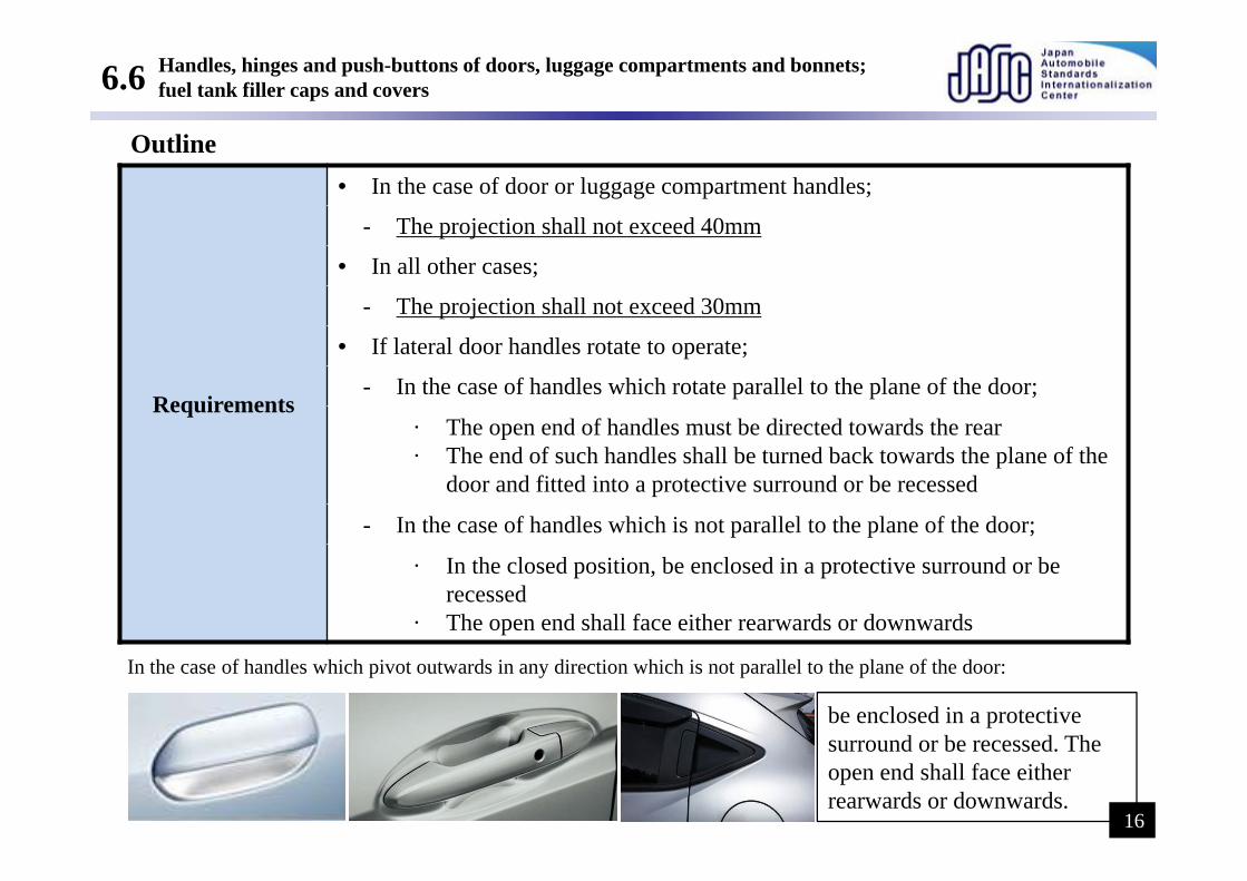
6.6 Handles, hinges and push-buttons of doors, luggage compartments and bonnets;fuel tank filler caps and covers
Requirements
• In the case of door or luggage compartment handles;
- The projection shall not exceed 40mm
• In all other cases;
- The projection shall not exceed 30mm
• If lateral door handles rotate to operate;
- In the case of handles which rotate parallel to the plane of the door;
· The open end of handles must be directed towards the rear· The end of such handles shall be turned back towards the plane of the
door and fitted into a protective surround or be recessed
- In the case of handles which is not parallel to the plane of the door;
· In the closed position, be enclosed in a protective surround or be recessed
· The open end shall face either rearwards or downwards
Outline
In the case of handles which pivot outwards in any direction which is not parallel to the plane of the door:
be enclosed in a protective surround or be recessed. The open end shall face either rearwards or downwards.
16

5 General specifications
6 Particular specifications
6.1 Ornaments
6.2 Headlights
6.3 Grilles and gaps
6.4 Windscreen wipers
6.5 Bumpers
6.6 Handles, hinges and push-buttons of doors, luggage compartments and bonnets;fuel tank filler caps and covers
6.7 Wheels, wheel nuts, hub caps and wheel discs
6.8 Sheet-metal edges
6.9 Body-panels
6.10 Lateral air or rain deflectors
6.11 Jacking brackets and exhaust pipes
6.12 Air intake and outlet flaps
6.13 Roof
6.14 Windows
6.15 Registration plate brackets
6.16 Luggage racks and ski racks
6.17 Aerials
3. Test Items

6.7 Wheels, wheel nuts, hub caps and wheel discs
ScopeWhen the vehicle is travelling in a straight line,no part of the wheels other than the tyres, situated above the horizontal plane passing through their axis of rotation
Requirements
• shall not exhibit any pointed or sharp projections that extend beyond the external plane of the wheel rim.
• shall project beyond the vertical projection, in a horizontal plane of the external surface or structure
Outline
This area is the scope of application
17

5 General specifications
6 Particular specifications
6.1 Ornaments
6.2 Headlights
6.3 Grilles and gaps
6.4 Windscreen wipers
6.5 Bumpers
6.6 Handles, hinges and push-buttons of doors, luggage compartments and bonnets;fuel tank filler caps and covers
6.7 Wheels, wheel nuts, hub caps and wheel discs
6.8 Sheet-metal edges
6.9 Body-panels
6.10 Lateral air or rain deflectors
6.11 Jacking brackets and exhaust pipes
6.12 Air intake and outlet flaps
6.13 Roof
6.14 Windows
6.15 Registration plate brackets
6.16 Luggage racks and ski racks
6.17 Aerials
3. Test Items

6.8 Sheet-metal edges
Scope• Sheet-metal edges, such as gutter edges and the rails of sliding doors• The requirements of the General specifications shall not apply to the rear edge
of bonnet and front edge of rear luggage boot.
Requirements
• shall not be permitted unless they are folded back, or
- shall be folded back by approximately 180deg., or- shall be folded towards the bodywork in such a manner that it cannot be
contacted by a sphere having a diameter of 100mm
• shall not be fitted with a shield meeting this Regulation
Outline
180deg.
18

5 General specifications
6 Particular specifications
6.1 Ornaments
6.2 Headlights
6.3 Grilles and gaps
6.4 Windscreen wipers
6.5 Bumpers
6.6 Handles, hinges and push-buttons of doors, luggage compartments and bonnets;fuel tank filler caps and covers
6.7 Wheels, wheel nuts, hub caps and wheel discs
6.8 Sheet-metal edges
6.9 Body-panels
6.10 Lateral air or rain deflectors
6.11 Jacking brackets and exhaust pipes
6.12 Air intake and outlet flaps
6.13 Roof
6.14 Windows
6.15 Registration plate brackets
6.16 Luggage racks and ski racks
6.17 Aerials
3. Test Items

6.9 Body-panels
RequirementsFolds in body panels may have a radius of curvature of less than 2.5 mm provided that it is not less than one-tenth of the height "H" of the projection
Outline
19

5 General specifications
6 Particular specifications
6.1 Ornaments
6.2 Headlights
6.3 Grilles and gaps
6.4 Windscreen wipers
6.5 Bumpers
6.6 Handles, hinges and push-buttons of doors, luggage compartments and bonnets;fuel tank filler caps and covers
6.7 Wheels, wheel nuts, hub caps and wheel discs
6.8 Sheet-metal edges
6.9 Body-panels
6.10 Lateral air or rain deflectors
6.11 Jacking brackets and exhaust pipes
6.12 Air intake and outlet flaps
6.13 Roof
6.14 Windows
6.15 Registration plate brackets
6.16 Luggage racks and ski racks
6.17 Aerials
3. Test Items

6.10 Lateral air or rain deflectors
Requirements shall have a radius of curvature of at least 1 mm on edges capable of being directed outwards
Outline
Lateral rain deflectors
20

5 General specifications
6 Particular specifications
6.1 Ornaments
6.2 Headlights
6.3 Grilles and gaps
6.4 Windscreen wipers
6.5 Bumpers
6.6 Handles, hinges and push-buttons of doors, luggage compartments and bonnets;fuel tank filler caps and covers
6.7 Wheels, wheel nuts, hub caps and wheel discs
6.8 Sheet-metal edges
6.9 Body-panels
6.10 Lateral air or rain deflectors
6.11 Jacking brackets and exhaust pipes
6.12 Air intake and outlet flaps
6.13 Roof
6.14 Windows
6.15 Registration plate brackets
6.16 Luggage racks and ski racks
6.17 Aerials
3. Test Items

6.11 Jacking brackets and exhaust pipes
Scope The vertical projection of the floor line lying vertically above Jacking brackets and exhaust pipes (radius of curvature is less than 2.5 mm)
Requirements shall not project more than 10 mm beyond this vertical projection
Outline
Floor line
the floor line lying vertically
10 mm or less
21

5 General specifications
6 Particular specifications
6.1 Ornaments
6.2 Headlights
6.3 Grilles and gaps
6.4 Windscreen wipers
6.5 Bumpers
6.6 Handles, hinges and push-buttons of doors, luggage compartments and bonnets;fuel tank filler caps and covers
6.7 Wheels, wheel nuts, hub caps and wheel discs
6.8 Sheet-metal edges
6.9 Body-panels
6.10 Lateral air or rain deflectors
6.11 Jacking brackets and exhaust pipes
6.12 Air intake and outlet flaps
6.13 Roof
6.14 Windows
6.15 Registration plate brackets
6.16 Luggage racks and ski racks
6.17 Aerials
3. Test Items

6.12 Air intake and outlet flaps
Condition In all positions of use
Requirements shall meet the requirements of the General specifications
Outline
22

5 General specifications
6 Particular specifications
6.1 Ornaments
6.2 Headlights
6.3 Grilles and gaps
6.4 Windscreen wipers
6.5 Bumpers
6.6 Handles, hinges and push-buttons of doors, luggage compartments and bonnets;fuel tank filler caps and covers
6.7 Wheels, wheel nuts, hub caps and wheel discs
6.8 Sheet-metal edges
6.9 Body-panels
6.10 Lateral air or rain deflectors
6.11 Jacking brackets and exhaust pipes
6.12 Air intake and outlet flaps
6.13 Roof
6.14 Windows
6.15 Registration plate brackets
6.16 Luggage racks and ski racks
6.17 Aerials
3. Test Items

6.13 Roof
Outline
Conditions
• Opening roofs;- only in the closed position
• Convertible vehicles
- examined with the hood in both the raised and lowered positions- With the hood lowered, no examination shall be made of the vehicle inside
an imaginary surface formed by the hood when in the raised position
Requirements shall meet the requirements of the General specifications
Opening roofs: Convertible vehicles:
23

5 General specifications
6 Particular specifications
6.1 Ornaments
6.2 Headlights
6.3 Grilles and gaps
6.4 Windscreen wipers
6.5 Bumpers
6.6 Handles, hinges and push-buttons of doors, luggage compartments and bonnets;fuel tank filler caps and covers
6.7 Wheels, wheel nuts, hub caps and wheel discs
6.8 Sheet-metal edges
6.9 Body-panels
6.10 Lateral air or rain deflectors
6.11 Jacking brackets and exhaust pipes
6.12 Air intake and outlet flaps
6.13 Roof
6.14 Windows
6.15 Registration plate brackets
6.16 Luggage racks and ski racks
6.17 Aerials
3. Test Items
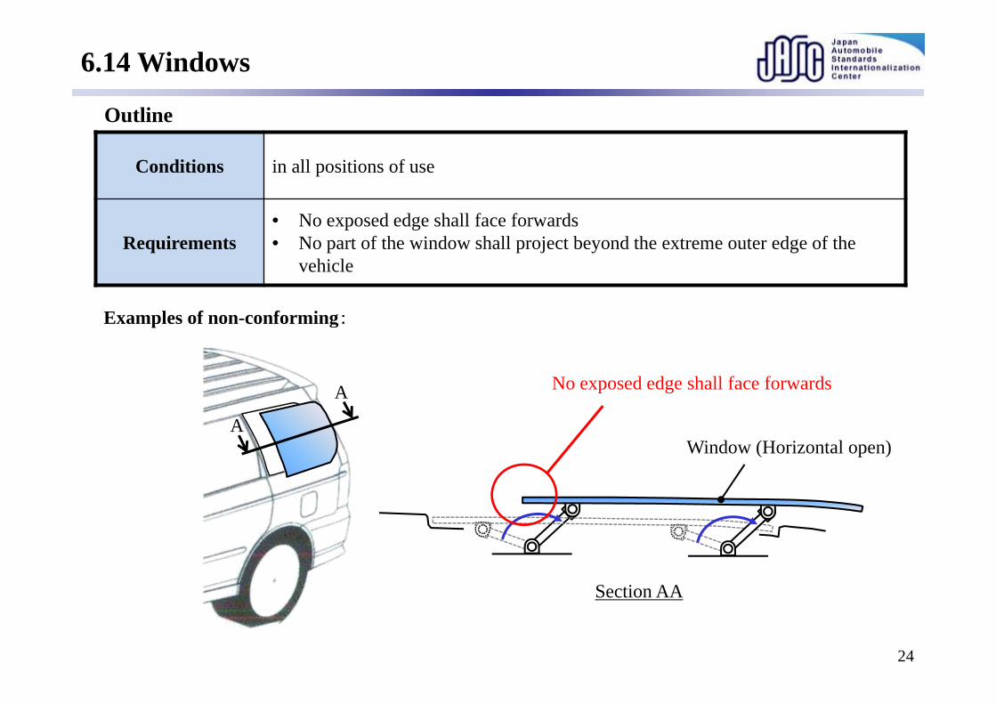
6.14 Windows
Outline
Conditions in all positions of use
Requirements• No exposed edge shall face forwards• No part of the window shall project beyond the extreme outer edge of the
vehicle
Examples of non-conforming:
A
AWindow (Horizontal open)
No exposed edge shall face forwards
Section AA
24

5 General specifications
6 Particular specifications
6.1 Ornaments
6.2 Headlights
6.3 Grilles and gaps
6.4 Windscreen wipers
6.5 Bumpers
6.6 Handles, hinges and push-buttons of doors, luggage compartments and bonnets;fuel tank filler caps and covers
6.7 Wheels, wheel nuts, hub caps and wheel discs
6.8 Sheet-metal edges
6.9 Body-panels
6.10 Lateral air or rain deflectors
6.11 Jacking brackets and exhaust pipes
6.12 Air intake and outlet flaps
6.13 Roof
6.14 Windows
6.15 Registration plate brackets
6.16 Luggage racks and ski racks
6.17 Aerials
3. Test Items

6.15 Registration plate brackets
Outline
Conditions A registration plate is fitted in accordance with the vehicle manufacturer's recommendation.
Scope Be contactable by a 100mm diameter sphere.* Registration plate is out of the scope of application
Requirements shall meet the requirements of the General specifications.
Registration plate fitted areas are out of the scope of application this requirements 25

5 General specifications
6 Particular specifications
6.1 Ornaments
6.2 Headlights
6.3 Grilles and gaps
6.4 Windscreen wipers
6.5 Bumpers
6.6 Handles, hinges and push-buttons of doors, luggage compartments and bonnets;fuel tank filler caps and covers
6.7 Wheels, wheel nuts, hub caps and wheel discs
6.8 Sheet-metal edges
6.9 Body-panels
6.10 Lateral air or rain deflectors
6.11 Jacking brackets and exhaust pipes
6.12 Air intake and outlet flaps
6.13 Roof
6.14 Windows
6.15 Registration plate brackets
6.16 Luggage racks and ski racks
6.17 Aerials
3. Test Items

6.16 Luggage racks and ski racks
Requirements
• shall be so attached to the vehicle that positive locking exists in at least one direction and that horizontal, longitudinal and transverse forces can be transmitted which are at least equal to the vertical load-bearing capacity of the rack as specified by its manufacturer.
• Racks;
- The external surface in contact with a sphere 165 mm in diameter shall have a radius of curvature more than 2.5 mm.
• Fastening elements;
- shall not project more than 40 mm beyond the surface in contact with a sphere 165 mm in diameter.
Outline
After installation of the rack;• Confirmation by contact with a sphere 165
mm in diameter.• Static load test** The test loads shall not be applied at one point only.
Racks
26

5 General specifications
6 Particular specifications
6.1 Ornaments
6.2 Headlights
6.3 Grilles and gaps
6.4 Windscreen wipers
6.5 Bumpers
6.6 Handles, hinges and push-buttons of doors, luggage compartments and bonnets;fuel tank filler caps and covers
6.7 Wheels, wheel nuts, hub caps and wheel discs
6.8 Sheet-metal edges
6.9 Body-panels
6.10 Lateral air or rain deflectors
6.11 Jacking brackets and exhaust pipes
6.12 Air intake and outlet flaps
6.13 Roof
6.14 Windows
6.15 Registration plate brackets
6.16 Luggage racks and ski racks
6.17 Aerials
3. Test Items

6.17 Aerials
Outline
Scope The aerial unattached end is less than 2 m from the road surface in any position of use specified by the manufacturer
Requirements
• shall be inside the zone bounded by the vertical planes which are 10 cm inside the extreme outer edge of the vehicle
• shall be fitted to the vehicle that no part of the aerials protrude beyond the extreme outer edge of the vehicle
• Shafts of aerials;
- may have radius of curvature of less than 2.5 mm
• Unattached ends of aerials;
- shall be fitted with fixed capping which shall have a radius of curvature more than 2.5 mm
• Bases of aerials (forward R point);
- shall not project more than 40 mm
• Bases of aerials (backward R point);
- It shall not project more than 70 mm.
27

6.17 Aerials
ROOF PANEL WIND SHIELD
SHARK-FINANTENNA
In case where shark-fin antenna is installed on a flat roof panel, it is measured from roof panel directly.
Details
Capping
Shafts
Bases of aerials (backward R point)ex. Shark-fin antennaBases of aerials (forward R point)
28
In the case of a component which is mounted on a convex surface

Terima kasih atas perhatian anda.
Thank you for your attention.

ECE No. 44Child Restraint Systems
Shunsuke Takagi(NTSEL Automobile Type Approval Test Department)

• Introduction
• Kinds and Category of CRS
• Requirements
• Vehicle fitting (UNECE R14 and R16)
• New CRS regulations (UNECE R129)
Contents

Child restraint system ("restraint") means (2.1)
Child restraint is not a seat for children, but a device that secures children to their seats (additional device for children) to provide protection from impacts in accidents.
Safety device similar to seatbelts
Child restraint system ("restraint") may comprise the combination of straps or
flexible components with a securing buckle, adjusting devices, attachments
and in some cases a supplementary device as a carry-cot, infant carrier,
a supplementary chair and/or an impact shield, capable of being anchored
to a power-driven vehicle. It is so designed as to diminish the risk of injury
to the wearer, in the event of a collision or of abrupt deceleration of the vehicle,
by limiting the mobility of the wearer's body.

MLIT website
When child is not placed in CRS, the death ratio increases 2.4 times than when placed in CRS

• Introduction
• Kinds and Category of CRS
• Requirements
• Vehicle fitting (UNECE R14 and R16)
• New CRS regulations (UNECE R129)
Contents


Category
Belt -secured type(two-point or 3-point belt)
ISOFIX Anchorages + Top Tether
ISOFIX Anchorages + Support leg
Support legISOFIX anchor
Top tether
ISOFIX anchor
ISOFIX Universal Semi-Universal ISOFIX(6.1.1.)Universal

Infant Toddler School age children
Weight less than 10 kg less than 9~18 kg less than 15~36 kg
Height up to 70 cm up to 65~100 cm up to 135 cm
Age newborn to 1 year old 1 to 4 yrs old 4 to 10 yrs old
CRS
Remark"rearward-facing" and "bed type"
Some can be used for both infants and children
Adult seatbelt is used
MLIT website

Category: 4 categories based on installed seat/vehicleMass Group: 5 groups based on weight of child
Possible configurations for groups / categories (6.1.3)
Group category Universal Semi-universal Restricted Specific vehicle
CRS ISOFIX CRS CRS ISOFIX CRS CRS ISOFIX CRS CRS ISOFIX CRS
0Carry-cot A NA A A A NA A A Rearward
facing A NA A A A NA A A
0+ Rearward facing A NA A A A NA A A
I
Rearward facing A NA A A A NA A A
Forward facing (integral) A A A A A NA A A
Forward facing (non-integral) NA NA NA NA NA NA NA NA
Forward facing (non-integral -see paragraph
6.1.12.)
A NA A NA A NA A A
II
Rearward facing A NA A NA A NA A A
Forward facing (integral) A NA A NA A NA A A
Forward facing (non integral) A NA A NA A NA A A
III
Rearward facing A NA A NA A NA A A
Forward facing (integral) A NA A NA A NA A A
Forward facing (non integral) A NA A NA A NA A A

2) ISOFIX CRS Size Category (2.1.1.6)1) Mass Group(2.1.1)
3) ISOFIX CRS Size combination (2.1.1.6)
Group Mass
Group 0 less than 10 kg;
Group 0+ less than 13 kg;
Group I from 9 kg to 18 kg;
Group II from 15 kg to 25 kg;
Group III from 22 kg to 36 kg.
Group MassGroup 0 E, F, G
Group 0+ C, D, E
Group I A, B, B1, C, D
ISOFIX size Explanation
A ISO/F3 Full Height Forward Facing toddler CRS
B ISO/F2 Reduced Height Forward Facing toddler CRS
B1 ISO/F2X Reduced Height Forward Facing Toddler CRS
C ISO/R3 Full Size Rearward Facing toddler CRS
D ISO/R2 Reduced Size Rearward Facing toddler CRS
E ISO/R1 Rearward Facing infant CRS
F ISO/L1 Left Lateral Facing position CRS (carry-cot)
G ISO/L2 Right Lateral Facing position CRS (carry-cot)

• Introduction
• Kinds and Category of CRS
• Requirements
• Vehicle fitting (UNECE R14 and R16)
• New CRS regulations (UNECE R129)
Contents

• Markings and Instructions
• Parts of CRS
• Entire CRS
Requirements

① Manufacturer's name/Initials/Trade mark (4.1)
Items indicated on child restraint (marking)
② Warning label for rearward-facing restraints (4.4~4.5)
③ ISOFIX Markings(4.8)
④ E marking / Approval number / Category (5.4)
ISOFIX design, Size
Method Marking
Label

⑤ Production year on plastic parts (4.2)
⑥ Indication of belt route (4.3)
Items indicated on CRS (marking)

Instructions
•15.2.6.
The method of installation illustrated by photographs and/or very clear drawings;

Check restraint performance and damageability in normal use
Lap strap load is transmitted through pelvis (Group I, II and III) (6.2.2)
Weak parts of body not subject to excessive stress (Group I, II and III) (6.2.2)
Distance between shoulder straps in vicinity of neck (at least width of neck) (6.2.3)
Compression load not imposed on crown of head (6.2.4)
Restraint performance
Sharp edges or protrusions liable to cause injury to occupant or damage
to clothing (6.2.5.1~6.2.5.2)
Exhibition of sharp edges capable of abrading straps (6.2.5.4)
Damageability

• Markings and Instructions
• Parts of CRS
• Entire CRS
Requirements

CRS Parts Name
Shoulder Strap(Harness & Cover)
Seat cushion
Tongue
Crotch Strap(Harness & Cover)
Adjusting deviceAdjuster belt
Adjuster lever
Buckle
Handle(pre loader)
Child Restraint Systems
Harness Belt
Lock-off device

Buckle (7.2.1, 8.2.1)
Adjusting device (7.2.2, 8.2.2, 8.2.3, 8.2.7, Annex 5, Annex 19)
Retractor (7.2.3, 8.2.4)
Strap (7.2.4, 8.2.5)
Lock-off device (7.2.5, 8.2.6)
ISOFIX attachment specification (7.2.6)
Dimension and area, operability, durability, releasing performance after
impact test, breaking load are specified for components of above
restraint device
Provisions applicable to individual components of the restraint (7.2.)

・Preclude possibility of incorrect manipulation precluded (Not left in partially closed position)Buckle lock only when all parts are engaged (7.2.1.1)
・Easy to operate and grasp/ release button of proper size / red colored (7.2.1.2 ~ 7.2.1.3)
・Release of child from restraint by single operation is possible (7.2.1.4)
Specification of individual required parts
・Range of adjustment sufficient to permit correct adjustment for all weight groups used (7.2.2.1)
・Quick adjuster type (7.2.2.2.)
・ Adjusting device within easy reach (7.2.2.3.)
・Equipped with crotch strap (All forward facing Group I CRS) (6.2.1.5)
・Minimum width of straps which connect dummy (7.2.4.1.1)
・Shall be permanently attached to child restraint (7.2.5.1.)
・Does not impair durability of adult belt(7.2.5.2.)
・Does not prevent rapid release of child(7.2.5.3.)
Buckle (7.2.1.)
Adjusting device (7.2.2.)
Strap (7.2.4.)
Lock-off device (7.2.5.)

Buckle (7.2.1, 8.2.1)
Other tests and requirements
- Buckles used in dynamic tests shall undergo 5,000±5
opening and closing cycles (7.2.1.7.)
- Buckles shall be capable of withstanding temperature test operation
requirements and repeated operation
TestBuckle Opening Test
Strength test (7.2.1.9、8.2.1.3.2., Annex 20)Under load (7.2.1.8.1) No load (7.2.1.8.2)
Test contents
Secure buckle on tester, measure opening force when pushing release button at given speed
Confirm load bearing strength of buckle by stretch test.
Test parts
Parts completing dynamic test
Unused partsNot specified
(number of samples: 2)
Condition Tension:200±2 N load Tension: no load Speed: 100±20 mm/min
Judge condition
Opening force:less than 80 N
Opening force:40-80 N
Mass group 0, 0+: 4,000 N
Mass group I or more: 10,000 N
Buckle load opening test
buckle
Rig for buckle opening
stroke

Adjusting device (7.2.2, 8.2.2, 8.2.3, 8.2.7, Annex 5, Annex 19)
① Adjustment (8.2.2)
Draw strap through adjustment device at rate of 100±20 mm/min
and check ease of adjustment
② Microslip test (8.2.3., Annex 5 Figure 3)
Arrange straps as shown in right figure, complete 1,000±5 cycles at
amplitude of 300±20 mm (30±10 cycles/min)
Test description
① Adjustment ( 7.2.2.4, 7.2.2.6)
Force required to operate device shall not exceed 50 N
② Microslip test (7.2.2.5)
・ Less than 25 mm for one adjusting device・ Less than 40 mm for all adjusting devices
Criteria(Ref.) micro slip test
Other tests
・Adjusting devices used in dynamic tests shall undergo
conditioning of 5,000±5 cycles. Conditioning tester


Retractor (7.2.3, 8.2.4)
Retracting force : belt assembly attached to manikin for measurement
Locking of ELR-type retractor : strap is extracted to check that locking occurs at given
length, position, acceleration
Durability of retracting mechanism: 5,000 cycles of withdrawal and retraction
Corrosion test : same as corrosion-resistance of completed product
Dust-resistance test : retraction and withdrawal after each agitation of dust
Test description
Retracting force
Part of lap belt: not less than 7 N
Part of chest restraint: not less than 2 N or more than 7 N
Locking of ELR-type retractor
Locking occurs when deceleration reaches 0.45 g, tilted more than 27 degrees
from installation position
Durability of retracting, corrosion test, dust-resistance test
Retractor shall continue to operate correctly after test
Criteria

Strap (7.2.4, 8.2.5)
After conditioning straps, conduct tensile strength test at a speed of 100±20 mm/min.
Test description
① Room conditioning② Special conditioning (light, cold, heat, exposure to water, abrasion)
Types of conditioning
① Room conditioningDifference between breaking loads of the 2 samples shall not exceed 10% of the greater of the two breaking loads measured.
② Special conditioning (light, cold, heat, exposure to water, abrasion)Not less than 75% of average of breaking load of the 2 samplesBreaking load- Group 0, 0+ & I: not less than 3.6 kN / Group II: not less than 5 kN- Group III: not less than 7.2 kN
Criteria

Class A & Class B devices (7.2.5.4, 7.2.5.5)
Amount of slip of webbing shall not exceed 25 mm.
Lock-off device (7.2.5, 8.2.6)
Class A device (8.2.6.1)
Place largest manikin in CRS, apply lock-off device, apply load to upper and
lower webbing (pulling direction) and check amount of slip.
Class B device (8.2.6.2)
Pass webbing through lock-off and frame according to manufacturer's instructions,
apply lock-off and attach mass (5.25±0.05 kg) to webbing. Allow mass to fall freely
from given height, and check amount of slip after certain number of cycles.
Test description
Criteria
Lock-off durability test
weight
free fall

Check resistance to repeated operations
Specification of ISOFIX attachment (7.2.6)
ISOFIX attachment and latching indicator shall undergo 2,000±5 opening and closing cycles under normal conditions of use.
Test description
Criteria
stroke direction ISOFIX attachment
latch indicator
ISOFIX bar
ISOFIX attachment / latch indicator resistance test

• Markings and Instructions
• Parts of CRS
• Entire CRS
Requirements

Resistance to corrosion (7.1.1, 8.1.1, Annex 4)
Check for deterioration likely to impair the functioning and no corrosion
Energy absorption (7.1.2, Annex 17, 18)
Check for impact absorption and impact area of head, area of impact
absorbing material
Overturning (7.1.3, 8.1.2)
Fix manikin in CRS and check retention performance when in upside
down position.
Dynamic test (7.1.4, 8.1.3, Annex 15)
Check for head excursion of dummy, chest acceleration, abdominal
penetration, failure or breakage of CRS after impact test.
Resistance to temperature (7.1.5, 7.2.1.7, 7.2.2.5, 7.2.5.2, 8.2.8)
Check for signs of deterioration likely to impair functioning of parts
liable to be affected by temperature.
Items to be checked on CRS (Entire product)

Nozzle
Test Sample
Nozzle
Resistance to corrosion (7.1.1, 8.1.1, Annex 4)
・Test time (50 hours)・Temperature in reservoir (35±5 ℃)・Concentration of salt solution(6.5-7.2 pH)・Pressure of compressed air(70 kN/m2-170 kN/m2)・Position of test sample(salt solution shall not drip directly on samples)
Controlled items
Place sample in salt solution reservoir, spray salt solution from nozzle andleave to stand for given time
Test description
No signs of deterioration likely to impair proper functioning shall be visible by visual inspection.
Criteria

Total mass2.75±0.05 kg(including accelerometer
Energy absorption (7.1.2 Annex 17, 18)
HeadformCRS Backrest (bottom right photo)
Test area
Fall from a height of 100 -0/+5 mm and measure acceleration of impact
Test description
Peak acceleration: less than 60 g
Criteria
high rigidity, within area contactable by manikin head
Impact point
Area to be impacted

Both smallest and largest appropriate manikin of the group(s) intended for use (8.1.2.7)
Manikin used
Fix CRS to test seat and rotate 540°at given speed.Apply mass equivalent to 4 times that of dummy.(400 mm/min)
Overturning (7.1.3, 8.1.2, Annex 23) rotating direction
Test description
Manikin head shall not move more than 300 mm from original position in vertical direction. (7.1.3.)
Criteria
Overturning tester

Resistance to temperature (7.1.5, 7.2.1.7, 7.2.2.5, 7.2.5.2, 8.2.8)
Buckle assembly, retractor, adjusting device, lock-off device, etc.
Place test sample in temperature cycle tester.Maintain in temperature of 100°(hot)→0°(cold)→23°(normal) for a given time.
Test description
Tested parts
No sign of deterioration likely to impair proper functioning shall be visible by visual inspection.
Criteria
Temperature cycle tester

Test conditions (8.1.3.4.)
Dynamic Tests
FRONTAL IMPACT REAR IMPACT
Test Restraint Speed (km/h) Test pulse
Stopping distance
during test (mm)
Speed (km/h) Test pulse
Stopping distance
during test (mm)
Trolley with test seat
Forward facing front and rear seats
universal, semi-universal or restricted
50 + 0 - 2 1 650 +/- 50 - - -
Rearward facing front and rear seats
universal, semi-universal or restricted
50 + 0 - 2 1 650 +/- 50 30 + 2 - 0 2 275 +/- 25
Vehicle body on trolley Forward facing 50 + 0 - 2 1 or 3 650 +/- 50 - - -
Rearward facing 50 + 0 - 2 1 or 3 650 +/- 50 30 + 2 - 0 2 or 4 275 +/- 25
Whole vehicle barrier test
Forward facing 50 + 0 - 2 3 not specified - - -
Rearward facing 50 + 0 - 2 3 not specified 30 + 2 - 0 4 not specified

P0 Dummy P1.5 Dummy P3/4, P3, P6, P10 Dummy
ECE Seat
Dynamic Tests (Tests and seat)

CRS and dummy are set according to paragraph 8.1.3.6 and Annex 21 of R44.
Check penetration of modelling clay, standard seatbelt is secured by specified tension, CRS strap is secured by specific load, etc.
Dimension of tools used to set dummy and calibration result of measuring instruments must also be checked.
Dummy Setting

・Restraint performance of manikin, breakage of attachment, etc.
・Resultant Chest Acceleration: 55 g (CFC180 Hz) (7.1.4.2.1)
・Vertical Component of the Acceleration :30 g (CFC180 Hz)(7.1.4.2.2)
・Abdominal Penetration: no visible signs of penetration
of the modeling clay.*1 (7.1.4.3.)
・Manikin displacement: within specified area (side view)
(specified area differs between forward-facing and rear-facing types) (7.1.4.4.)
CRS installed with manikin is set on test seat fixed on trolley,
and projected so as to create impact similar to impact created
by vehicle impact.(2 patterns (front impact and rear impact))
Dynamic Tests (7.1.4, 8.1.3)
Test description
Criteria
*1 Set up of the clay model
Clay

Total velocity change (8.1.3.1.1.3.2)
frontal impact: 52+0/-2 km/hrear impact : 32+2/-0 km/h
Dynamic Tests (7.1.4, 8.1.3)
Manikin Dummy Mass
Infants* P0 -
9 months P3/4 9kg
18 months P1.5 11kg
3 Years P3 15kg
6 Years P6 22kg
10 Years P10 32kg
Manikin used (8.1.3.7., Annex 8)
*No chest acceleration as it is not instrumented.
Front Impact Rear Impact
Trolley accelerationwithin specified corridor
EC seat (Annex 6)
EC Seat Rig (Annex 6)
Group Dummy (8.1.3.7)
Group 0 P0, P3/4Group 0+ P0, P1.5Group I P3/4, P3Group II P3, P6Group III P6. P10 Sled


Acceleration curve and velocity
Front Impact Rear Impact
Velocity :50.0~52.0 km/h Velocity :32.0~34.0 km/h*However, if the tests above were performed at a higher speed and/or the acceleration curve has exceeded the upper level of the
hatched area and the child restraint meets the requirements, the test shall be considered satisfactory.
CFC60 HzCFC60 Hz

• Introduction
• Kinds and Category of CRS
• Requirements
• Vehicle fitting (UNECE R14 and R16)
• New CRS regulations (UNECE R129)
Contents

CRS fitting in Vehicle
CRS type Belt ISOFIX
UNECE Number14 Seatbelt anchorages -
Bar and Tether StrengthBar and Tether Position
Fitting
UNECE Number16 Seatbelt
Recommended CRS FittingFittingFitting
Belt Webbing


ISOFIX top tether anchorage

①Latch the Buckle
③Webbing slack is remove
③ ⑥
⑥
⑦

47
①100N±10N
②Attach the CRF to the ISOFIX anchorages system
③100N±10N④CRF base pitch angle

• Introduction
• Kinds and Category of CRS
• Requirements
• Vehicle fitting (UNECE R14 and R16)
• New CRS regulations (UNECE R129)
Contents

Q and P dummy
Q dummies (R129) P dummies (R44)

UN Regulation 89
Speed Limitation Device (SLD)for Heavy‐Duty Vehicles
Mitsuharu YonezawaHino Motors Ltd. Technical Management Div
A. IntroductionA‐1. Purpose of UN R89A‐2. ApplicabilityA‐3. ConstructionA‐4. Definition
B. Technical Requirements
CONTENTS

A. Introduction

A‐1. Purpose of UN R NO. 89
The purpose of this regulation is to limit the maximum speed of heavy‐duty vehicles to a specified value by a speed limitation device (SLD).
SLD is a device which limit the fuel feed to the engine under the control of engine ECU.
A. Introduction

This regulation is applicable toN2, N3, and M3.
A‐2. Applicability
M1 N1
M2 N2M3 N3
A. Introduction

A‐3. Construction
Regulation 89 consists of following 3 parts.PART I: Approval of Vehicles fitted with SLDPART II: Approval of SLDPART III: Approval of Vehicle fitted with SLD
which is already approved under PART II.
A. Introduction
Usually,vehicle SLD is controlled with its own engine ECU, and we vehicle manufacturers use PART I. Therefore, today, I would like to explain this PART I. The most requirements of PART II and PART III are all common to this PART I.

A‐4. Definition
1) Make and type2) Range of speed limit3) Ratio of maximum engine power/unladen mass
is less than or equal to that of tested vehicles 4) The highest ratio of engine speed/vehicle speed in top gear is less than or equal to the tested vehicle.
Vehicle TypeVehicle type means vehicles which do not differ in such essential respect as:This is the fundamental definition to determine the “vehicle type” and select a test vehicle from the group.

B. Technical Requirement

B‐1. Design Requirement
1) Tamper‐proof on SLDSection 5.1.2 requires tamper‐proof on SLD.Previously, the fuel cut to limit the vehicle speed wascontrolled by mechanical injection system,which needed the sealing on adjustable design parameters to protect against tampering.
But today, most of the fuel injection is controlled by engine ECU. If someone tries to modify the engine ECU, it will affect other important vehicle performance. So it is technically in feasible to attempt to tamper the speed limit settings.

B‐1. Design Requirement
Section 5.1.9 requires checking function on SLD while vehicle is stationary in order to confirm the activation of SLD visually.
SLD
2) Checking function on SLD performance
If the SLD is controlled by engine ECU,the warning lamp for general engine check lamp can be used in place of “SLD” warning lamp.

B‐2. Test Requirement
Annex 5 describes the technical requirementon speed limiter test with 2 options.
(1.1) Measurement on Test Track(1.2) Measurement of Chassis dynamometer
1)Speed Limiter Test
As chassis dynamometer for heavy‐duty vehicles are not so easily available for use, we usually conduct the test on test track.

B‐2. Test Requirement
1) Speed Limiter Test
Test Track Measurement consists of following two tests.
(a) Acceleration test method
(b) Steady speed test method

ConditionsVehicle setting: Manufacturers recommendation Vehicle mass: UnladenRoad surface: Grade of 2% or lessClimate condition: Average wind velocity < 6m/s
Gusts wind velocity <10 m/s
B‐2. Test Requirement
1) Speed Limiter Test(a) Acceleration Test:

Acceleration Test Method (1/11)
Speed
Time
Max10s
Vmax
Vset
Vstab
1.05xVstab
Minimum 30s
4%Vstab
(Vset-10)km/h
Annex5 1.1.4.2.4.

Acceleration Test Method (2/11)1.1.4.1The vehicle running at a speed which is 10 km/h below the set‐speed(Vset) shall be accelerated as much as possible using on the accelerator control.
1.05 x Vstab
Vmax
Vset
Vstab
> (Vset‐10)km/h
Speed
TimeAcceleration start speed
Vset is the highest design speedcontrolled by SLD.

Acceleration Test Method (3/11)1.1.4.1
Depress the acceleration pedal at full throttle and it shall be maintained at least 30 seconds after the vehicle speed has been stabilized.
1.05 xVstab
Vmax
Vset
Vstab
30s minSpeed
Time

Acceleration Test Method (4/11)1.1.4.2.1The stabilized speed reached by the vehicle shall not exceed the set speed (Vstab <Vset). However, a tolerance of 5% of the Vset value, or 5 km/h, whichever is the greater, is acceptable
Vmax
Vset
Vstab
1.05 xVstab
Speed
Time
< 5% of the Vset value, or 5 km/h,
Vstab is the actual highestspeed controlled by SLD.
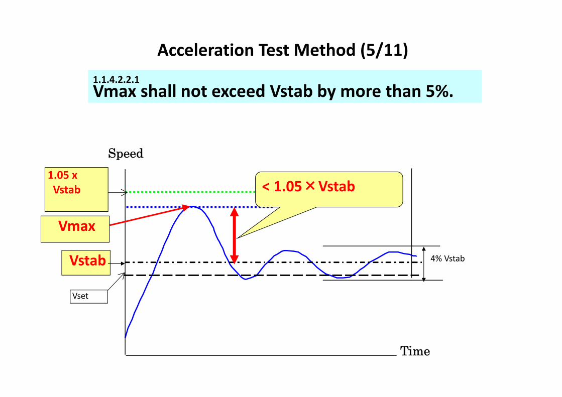
1.1.4.2.2.1Vmax shall not exceed Vstab by more than 5%.
Acceleration Test Method (5/11)
4% Vstab
Speed
Time
< 1.05×Vstab1.05 xVstab
Vmax
Vset
Vstab

Acceleration Test Method (6/11)1.1.4.2.2.2The rate of change of speed (from Vmax to Vset) shall not exceed 0.5 m/s2
Time
1.05 xVstab
Vmax
Vset
Vstab 4% Vstab
Speed
Max. slope:< 0.5m/s2

Acceleration Test Method (7/11)1.1.4.2.2.3The stabilized speed conditions specified .shall be attained within 10 s of first reaching Vstab;
4% Vstab
1.05 xVstab
Vmax
Vset
Vstab
(Vset‐10)km/h
Speed
Time
< 10sec

Acceleration Test Method (8/11)
1.1.4.2.3.1
Stable speed shall not vary by more than 4% of Vstab or 2 km/h whichever is greater; is acceptable
1.05 x Vstb
Vmax
Vstab
Vset
Time
Speed
4% Vstabor 2km/h

1.1.4.2.3.2
The rate of change of speed shall not exceed 0.2 m/s2
1.05 x Vstb
Vmax
Vstab
Vset
Speed
TimeMax. slope:< 0.2m/s2
Acceleration Test Method (9/11)

Test Result (Sample)
85
90
95
100
105
0 1 2 3 4 5 6 7 8 9 10 11 12 13 14 15 16 17 18 19 20 21 22 23 24 25 26 27 28
Vset : 98.0 km/h Vstab: 98.4 km/h Vmax: 99.1 km/h ① : 0.15m/s2 ② : 0.05m/s2
①②
Velo
city km
/h
Time sec

l.1.4.2 4.Tests in acceleration shall be carried out and the acceptance criteria verified for each gear ratio allowing in theory the set speed to be exceeded.
Acceleration Test Method (11/11)
5th
Vset
Vehicle speed
No test needed
Test
Maxenginespeed
1st2nd
4th
3nd
Acceleration testing shall be carryed out all gears may exceed the Vset

B‐2. Test Requirement
Vehicle setting: Manufacturers recommendation Vehicle mass: UnladenRoad surface: Grade of 2% or lessClimate condition: Average wind velocity <6m/s
Gusts wind velocity <10 m/s
1) Speed Limiter Test
(b) Steady‐speed Test
Conditions are all the same as those of acceleration test.

Steady Speed Test Method:
400m
・Run the test vehicle at least 400 m with maintaining the Vstab controlled by SLD.・Then the same test will be carried out in the opposite direction on the same test track.・Repeat this test 5 times.

Steady Speed Test Method:
Vstab
Vset
Time
SpeedVstab +4% Vset
or +5km/h
On each test run Vstab shall not exceed Vset. However, a tolerance of 5% of the Vset value, or 5 km/h, whichever is the greater, is acceptable.

Tests in Steady Speed shall be carried out and the acceptance criteria verified for each gear ratio allowing in theory the set speed to be exceeded.
Steady Speed Test Method:
Vset
Vehicle speed
No test needed Test
Maxenginespeed
1st2nd
4th 5th
3nd

B‐2. Test Requirement
Only applicable to SLD using mechanical fuel injection system.
2) Durability Test
Therefore, SLD controlled by engine ECU,this requirement is not applicable.

UN Regulation 89Speedlimiter for Heavy‐Duty Vehicles
Thank you for listening to my explanation.
Thank you

Report on the 43rd JASIC Asia Expert Meeting
(R26, R44, R89)
Replaced due to editorial correction: March 31, 2016 October 23, 2015
Date: Monday, October 5, 2015, 9:00-12:00 Tuesday, October 6, 2015, 9:30-13:00 Place: JPJ Meeting Room, Putrajaya, Malaysia (October 5)
JPJ Meeting Room, Cyberjaya, Malaysia (October 6) Participants: Malaysian side: About 52 people attended the meeting, including: Those from JPJ:
MR. MOHD SHARUULNIZAM BIN SARIP (Deputy Director) MR. AZZAHARIN BIN ALLIAS MR. AZIZUL BIN ABDUL AZIZ MR. MUHAMAD ARIF FAHMI BIN ABDUL WAHAB MR. MOHD AFFIZUL ARIFF BIN SALIM MR. SYED NUR ADAF ZHAFRY BIN ISMAL
Japanese side: Mr. Kikuchi (Honda/JASIC), Mr. Takagi (Automobile Type Approval Test Dept., NTSEL), Mr. Yonezawa (Hino/JASIC), Mr. Yamagata (JASIC), Mr. Korenori (JASIC Jakarta) Day 1: Detailed examination of the check list drafted by JPJ Day 2: Presentations by experts and Q&A
Overview Monday, October 5 - The participants discussed the checklist for UN-R26 that was ready as of October 5. - As to the checklists for the remaining UN-R44 and UN-R89, it was agreed that after the completion by
JPJ, they would be sent to JASIC, distributed to experts and examined later. - The experts gave 14 comments on the checklist for UN-R26 (See Attached Table 1), which, after a
discussion, the participants agreed to all reflect on the checklist. Tuesday, October 6 - First, Mr. Sharuulnizam Bin Sarip, Deputy Director, JPJ, gave a speech. Since joining the 1958
Agreement in 2006, Malaysia has adopted 78 UN Regulations, including the three Regulations on the agenda of the Expert Meeting today. He hoped this meeting would stimulate an active discussion and contribute to enhancing the understanding of the issues by parties concerned.
- On behalf of JASIC, Mr. Yamagata expressed gratitude to JPJ and the participants for their cooperation in making the meeting a success. He hoped that, as the top runner in harmonization efforts in ASEAN, Malaysia would keep making the best use of Expert Meetings and set an example in developing AMS.
- Thereafter presentations were given in the order of UN-R26 (External Projections), UN-R44 (Child Restraint Systems), and UN-R89 (Speed Limitation Devices). Each presentation was followed by an active Q&A session and enhanced the understanding of the participants. (See Attached Table 2 for Q&A)


(Table 1) Comments on the checklist for UN-R26
No. SubjectParagraph
No.Experts’ comments JPJ’s conclusion Remark
1 Model - How about adding the model year? We will add that as a reference.
The model year will be given in such a way that itdoesn’t look like a different new model every modelyear despite there being any change in thespecifications.
2 General Specification Para.5Is a space for checking general requirements necessary, such as2.5R or more?
The space will be included. -
3 Grilles and gaps Para.6.3
We see parts to be checked are fixed, but isn’t that parts to bechecked change from a model to another?Some manufacturers make a list of parts to be checked for eachrequirement by model.
We will get an example of such achecklist from Mr. Kikuchi and refine ourlists based on that.
An example list was provided to JPJ after themeeting.
4 Hadle, Hinges etc.Para.6.6.2.1Para.6.6.2.2
How about adding requirements such as “When handles rotateparallel to the plane of the door, the open end of handles must bedirected towards the rear.”?
That will be added. -
5 Wheel Para.7.3How about adding requirements such as “The wheel shall notexceed the outermost end of the body, or, otherwise shall satisfythe requirement of R30”?
That will be added. -
6 Body Panels Para.6.9.1
Since the measurement is done by toutching the panel with a 165mm sphere, with the body panel bent inward, actually verifying thecompliance is difficult. We suggest that you verify that with thelayout data.
If actual measurement is difficult, we willverify with the layout data, but we wouldlike to stick to the principle as far asindividual parts allows that.
-
7Jacking brackets andexhaust pipes
Para.6.11.1There is an exemption provision that if the part satisfies the “R2.5or more” requirement, the value may exceed 10 mm. How aboutadding that?
A foot note will be added to that effect.
JPJ asked if there’s no limit to the projection as faras the part satisfies the “R2.5 or more”requirement. The experts answered that that woulddepend on the result of consultation with theauthority.
8 Roof Para.6.13What is indicated in the list is test conditions only, with noreference to requirement (R2.5 or more).
The requirement will be added.Considering that only the paragraph 6.13 includingtesting conditions is much specific, the expertssuggest following the crowd.
9 Windows Para.6.14The idea of requirement for the “sharp edge” is that, as far asthere’s no harm when the engineer touches the edge, that will beOK. There’s no requirement with specific figures.
Understood.
JPJ asked if an edge isn’t sharp as far as that'sR2.5 or more. The experts answered that’s right,but warned against indicating so with specificfigures.
10Registration platebrackets
Para.6.15What is indicated in the list is test conditions only, with noreference to requirement (R2.5 or more).
The requirement will be added. The same as the roof above.
11Luggage racks and skiracks
Para.6.16 There’s no reference to the requirement for the rack load test. That will be added.
The test conditions are not very clear and dependon the discretion of the manufacturer. It's possibleyou can do that with desktop calculation inconsultation with the testing laboratory, but theprinciple is verification with actual vehicles.However, the regulation doesn't take care ofaccessory parts with which automakers are not fullyinvolved.
12 Para.6.17.1
How about adding the requirement that “The requirement for R2.5shall not apply if the aerial exceeds 2 m”, and that “The aerialshall be installed at 10 cm or more inward from the outermost endof the vehicle” ?
Those will be added.There’s few cases that exceed 2 m amongpassenger cars.
13 Para.6.17.2
Isn’t it necessary to add the requirement that the 40 mmrequirements applies to aerials installed in front of the driver, the70 mm requirement shall apply when the aerial is installedbackward of the driver?How about adding also the requirement that this shall not apply toaerials exceeding 2 m?
Those will be added.For example, the 70 mm requirement applies to ashark aerial installed in the rear.
14 Para.6.17
How about adding the exemption provision that, when the aerialbends under a load of 50 daN or more, the requirement shall applyto the part coming under that bending point?How about adding the exemption provision that, in case of aflexible aerial, the requirement shall apply to the part coming underthat base?
Those will be added. -
Aerials

(Table 2) Q&A at the Expert Meetings on UN-R26, 44, and 89
No. UN-R Question Answer
1
About accessory parts: There are many different patterns, including i)genuine parts prescribed by automakers; ii) parts independentlydefined by affiliated dealers; and iii) parts available on the market.What’s the idea underlying the regulations in ensuring regulatorycompliance?
As to specifications subject to the whole-vehicle type approval, all partsmust comply with relevant regulations, whether they are genuine oroptional or whether they are defined by automakers or dealers, andautomakers are taking care of this at their own responsibility.On the other hand, as to other accessory parts sold on the markets out ofautomakers’ sight, it lies upon parts manufacturers to ensure regulatorycompliance, but whether they actually do so might be a gray area.
2 How should we handle COP with the three patterns above?
With COP in Europe and Japan, basically vehicles are checked in theirdefault status. Therefore, if accessory parts are included in the whole-vehicle type approval test, then parts in i) and ii) above are subject toCOP requirement.As to parts available on the markets without type approval such as thosecited in iii) above, usually they are not subject to the COP requirement.That is to say, as we stated above, it lies upon those parts manufacturersto independently have their products comply with relevant regulations.
3What kind of requirements apply to parts comprising CRS? Is markingrequired for them? And when they are applied, will the manufacturer’sown label do, as far as it testifies that the product is in compliance?
The requirements for each part are prescribed mainly in paragraph 6, butthey are also indicated throughout the regulation wherever deemedappropriate. So please check them all carefully throughout the regulation.As to their outline, that's as we presented in this meeting.CRS requires marking for compliant assemblies, but not for individualparts, except for certain products (such as plastic products).As to manufacturers’ own labels, it is up to the engineer to determinewhether they are compliant or not. If they find no problem with proprietarylabels, then there won’t be any problem with such labels.
4 Which parts are subject to corrosion tests? Metallic parts. The tests see how corrosion has progressed.
5There are three categories for CRS. Is there any universal CRS thatwould cover all ranges? If any, could you tell me the manufacturer’sname?
That depends on the CRS, but some cover two or three categories.Takata’s CRS, for example, covers three categories.
6Does every category have its own restriction as to the size of theoccupant, such as the height between the hip to the shoulders?
There provisions such as "6.2.4 The design shall be such thatcompression loads shall not be imposed on the crown of the child's headin the event of a collision," so we check the height after installing thedummy. Further, when it doubles as groups as in 6.2.7, there areseparate requirements.
7
About the frontal and rear collision in the dynamic tests: I see thattolerance for the colliding speed is given downward (+0-2) for thefrontal collision but upward (+2-0) for the rear collision. Why thisdifference?
That’s only difference in legal expression. Technically there’s nodifference.
UN-R26
UN-R44

8 What's the difference between the P dummy and the Q dummy?They are totally different dummies with different biological fidelity,measurable body parts, etc. The Q dummy cannot be used for R44.
9CRS includes a variety of sizes and geometries. Is there any casewhere you have to change the design of the seat belt?
For the purpose of UN-R16, once you verify that the seat belt is properlyworn with a gabarit, usually there won't be any change in its handling ordesign.However, when the automaker wants to recommend large CRS to small-sized vehicles, then they might have to change the design of the seat beltto accommodate that on the vehicle side.
10
R89 concerns such categories as N2, N3, and M3. Are therequirements presented today all apply commonly to all of thesecategories? Or are there different requirements depending on thecategory?
The presentation today, including the video clips, typically concerns N3,but yes, they cover all of the three categories.
11In Japan, are the speed limits defined for each category? And arethey defined by the Japanese government?
In case of N3, for example, the speed limit is defined at 90 km/h by theJapanese government. For the purpose of the Road Traffic Act, thespeed limit is set at 80 km/h.
UN-R89
UN-R44


![[43rd KUG PP] iPhone Storm](https://img.pdfslide.us/doc/110x75/54b891f74a795982368b45ac/43rd-kug-pp-iphone-storm.jpg)