Embed Size (px)
Citation preview
Northeast Tennessee Water Quality BMP Manual
4.3.11 Modular Porous Paver Systems General Application Water Quality BMP
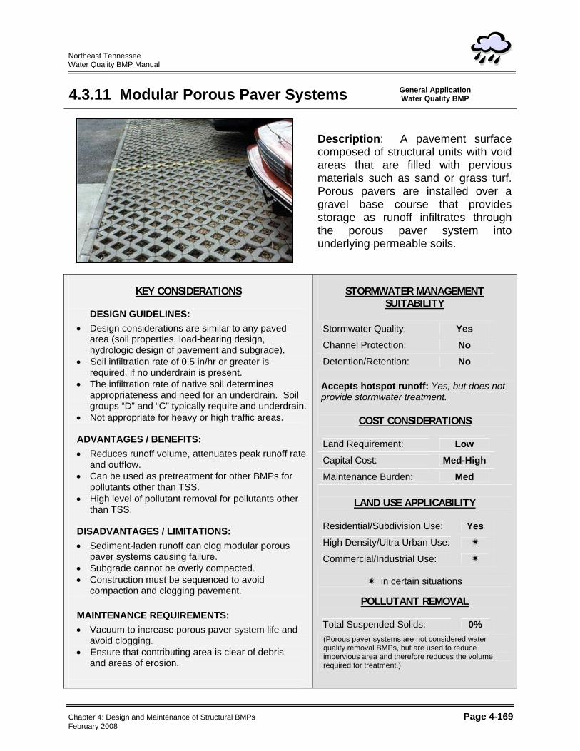
Description: A pavement surface composed of structural units with void areas that are filled with pervious materials such as sand or grass turf. Porous pavers are installed over a gravel base course that provides storage as runoff infiltrates through the porous paver system into underlying permeable soils.
KEY CONSIDERATIONS
DESIGN GUIDELINES:
• Design considerations are similar to any paved area (soil properties, load-bearing design, hydrologic design of pavement and subgrade).
• Soil infiltration rate of 0.5 in/hr or greater is required, if no underdrain is present.
• The infiltration rate of native soil determines appropriateness and need for an underdrain. Soil groups “D” and “C” typically require and underdrain.
• Not appropriate for heavy or high traffic areas. ADVANTAGES / BENEFITS: • Reduces runoff volume, attenuates peak runoff rate
and outflow. • Can be used as pretreatment for other BMPs for
pollutants other than TSS. • High level of pollutant removal for pollutants other
than TSS. DISADVANTAGES / LIMITATIONS: • Sediment-laden runoff can clog modular porous
paver systems causing failure. • Subgrade cannot be overly compacted. • Construction must be sequenced to avoid
compaction and clogging pavement. MAINTENANCE REQUIREMENTS: • Vacuum to increase porous paver system life and
avoid clogging. • Ensure that contributing area is clear of debris
and areas of erosion.
STORMWATER MANAGEMENT
SUITABILITY Stormwater Quality: Yes Channel Protection: No Detention/Retention: No Accepts hotspot runoff: Yes, but does not provide stormwater treatment.
COST CONSIDERATIONS
Land Requirement: Low Capital Cost: Med-High Maintenance Burden: Med
LAND USE APPLICABILITY
Residential/Subdivision Use: Yes High Density/Ultra Urban Use:
Commercial/Industrial Use:
in certain situations
POLLUTANT REMOVAL
Total Suspended Solids: 0%
(Porous paver systems are not considered water quality removal BMPs, but are used to reduce impervious area and therefore reduces the volume required for treatment.)
Chapter 4: Design and Maintenance of Structural BMPs Page 4-169 February 2008
Northeast Tennessee Water Quality BMP Manual
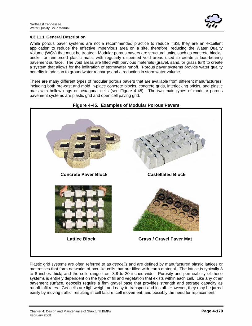
4.3.11.1 General Description While porous paver systems are not a recommended practice to reduce TSS, they are an excellent application to reduce the effective impervious area on a site, therefore, reducing the Water Quality Volume (WQv) that must be treated. Modular porous pavers are structural units, such as concrete blocks, bricks, or reinforced plastic mats, with regularly dispersed void areas used to create a load-bearing pavement surface. The void areas are filled with pervious materials (gravel, sand, or grass turf) to create a system that allows for the infiltration of stormwater runoff. Porous paver systems provide water quality benefits in addition to groundwater recharge and a reduction in stormwater volume. There are many different types of modular porous pavers that are available from different manufacturers, including both pre-cast and mold in-place concrete blocks, concrete grids, interlocking bricks, and plastic mats with hollow rings or hexagonal cells (see Figure 4-45). The two main types of modular porous pavement systems are plastic grid and open cell paving grid.
Figure 4-45. Examples of Modular Porous Pavers
Concrete Paver Block Castellated Block
Lattice Block Grass / Gravel Paver Mat
Concrete Paver Block Castellated Block
Lattice Block Grass / Gravel Paver Mat
Plastic grid systems are often referred to as geocells and are defined by manufactured plastic lattices or mattresses that form networks of box-like cells that are filled with earth material. The lattice is typically 3 to 8 inches thick, and the cells range from 8.8 to 20 inches wide. Porosity and permeability of these systems is entirely dependent on the type of fill and vegetation that exists within each cell. Like any other pavement surface, geocells require a firm gravel base that provides strength and storage capacity as runoff infiltrates. Geocells are lightweight and easy to transport and install. However, they may be jarred easily by moving traffic, resulting in cell failure, cell movement, and possibly the need for replacement.
Chapter 4: Design and Maintenance of Structural BMPs Page 4-170 February 2008
Northeast Tennessee Water Quality BMP Manual
Open cell paving grids, commonly called block pavers or grid pavers, are structural units, such as concrete blocks or bricks with regularly spaced voids that penetrate their entire thickness. Grids are made of concrete or brick and the open cells are filled with porous aggregate or vegetated soil. Block pavers are more rigid and, therefore, can bear larger traffic loads than plastic grid systems. Modular porous pavement systems are typically placed on a gravel (stone aggregate) base course. Runoff infiltrates through the porous paver surface into the gravel base course, which acts as a storage reservoir as it infiltrates to the underlying soil. The infiltration rate of the soils in the subgrade must be adequate to support drawdown of the entire runoff capture volume within 24 to 48 hours. If the surrounding soil infiltration is insufficient or if the potential for contamination of groundwater exists from pollutants such as chemicals, fertilizers, petroleum products, fats or greases, an underdrain is required to allow discharge of the runoff to additional BMPs for treatment. Additionally, special care must be taken during construction to avoid undue compaction of the underlying soils, which could affect the soils’ infiltration capability. Construction and maintenance costs and requirements should be considered when utilizing porous paver systems. Modular porous paver systems require a high level of construction workmanship to ensure that they function as designed. In addition, the repair or replacement of the surfaces can be costly should they become clogged. 4.3.11.2 Stormwater Management Suitability Porous paver systems can not be used for stormwater treatment (i.e., 80% TSS removal) or flood control. The major benefit in using these systems lies in the overall reduction of stormwater runoff that can be provided. Areas covered by porous paver systems can be considered as pervious surfaces, thereby reducing water quality treatment and channel protection volumes, and flood protection peak discharges. Water Quality (WQv) Porous paver systems do not have the ability to provide stormwater quality treatment for total suspended solids (TSS). However, these systems provide for infiltration of stormwater and can provide for the removal of other pollutants, such as hydrocarbons (e.g., motor oil and gasoline). 4.3.11.3 Pollutant Removal Capabilities Porous paver systems provide for the infiltration of stormwater runoff and they have a high removal rate of soluble pollutants. Pollutants become trapped and are then absorbed or broken down in the underlying soil layers. However, due to the potential for clogging, porous paver surfaces shall not be used for the removal of sediment or other particulate pollutants. 4.3.11.4 Application and Feasibility Criteria Modular porous paver systems are typically used in low-traffic areas, such as: • parking pads in parking lots; • overflow parking areas; • residential driveways; • residential street parking lanes; • recreational trails; • golf cart and pedestrian paths; and • emergency vehicle and fire access lanes. Porous paver systems shall not be used in high traffic areas due to the potential for cell compaction and failure. Examples of paver systems that have been used for some of the above listed applications are presented in Figures 4-46 and 4-47.
Chapter 4: Design and Maintenance of Structural BMPs Page 4-171 February 2008
Northeast Tennessee Water Quality BMP Manual
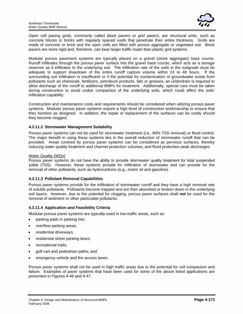
Figure 4-46. Examples of Porous Paver Surfaces (Sources: Invisible Structures, Inc.; EP Henry Corp.)
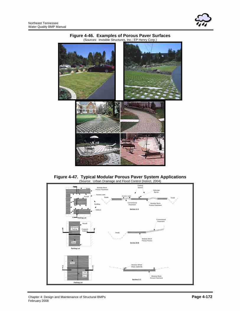
Figure 4-47. Typical Modular Porous Paver System Applications (Source: Urban Drainage and Flood Control District, 2004)
Modular BlockPorous Pavement
Access Lane
Building
Slope
Runoff
A
Section A-A
Parking Lot
A
SwaleAccess Lane
ParkingSpaces
VehicularBarrier
Modular Block Porous Pavement
ConventionalPavement
Swale
InfrequentParking
Slope
Runoff
FrequentParking
Parking Lot
B B
Swale
Modular BlockPorous Pavers
ConventionalPavement
Section B-B
Slope
CellWalls(typ.)
C
Parking Lot
Section C-C
Modular BlockPorous Pavement
Modular WheelStops (optional)C
SWALE
Chapter 4: Design and Maintenance of Structural BMPs Page 4-172 February 2008
Northeast Tennessee Water Quality BMP Manual
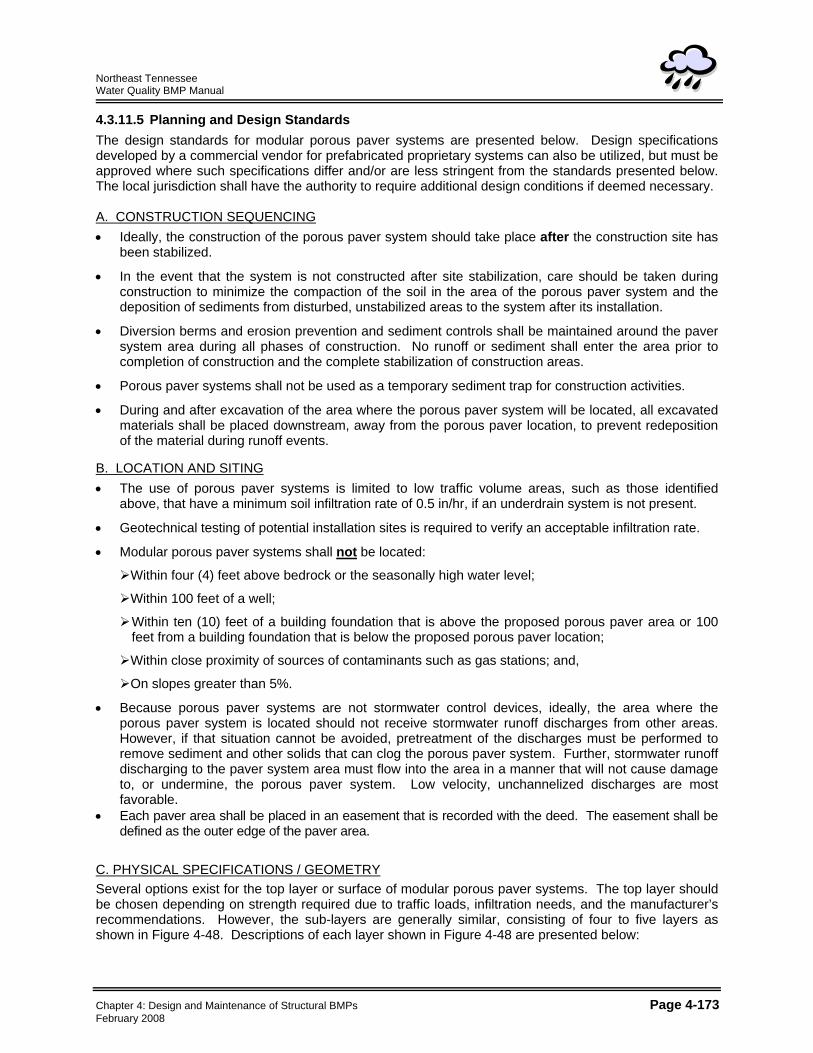
4.3.11.5 Planning and Design Standards The design standards for modular porous paver systems are presented below. Design specifications developed by a commercial vendor for prefabricated proprietary systems can also be utilized, but must be approved where such specifications differ and/or are less stringent from the standards presented below. The local jurisdiction shall have the authority to require additional design conditions if deemed necessary. A. CONSTRUCTION SEQUENCING • Ideally, the construction of the porous paver system should take place after the construction site has
been stabilized.
• In the event that the system is not constructed after site stabilization, care should be taken during construction to minimize the compaction of the soil in the area of the porous paver system and the deposition of sediments from disturbed, unstabilized areas to the system after its installation.
• Diversion berms and erosion prevention and sediment controls shall be maintained around the paver system area during all phases of construction. No runoff or sediment shall enter the area prior to completion of construction and the complete stabilization of construction areas.
• Porous paver systems shall not be used as a temporary sediment trap for construction activities.
• During and after excavation of the area where the porous paver system will be located, all excavated materials shall be placed downstream, away from the porous paver location, to prevent redeposition of the material during runoff events.
B. LOCATION AND SITING • The use of porous paver systems is limited to low traffic volume areas, such as those identified
above, that have a minimum soil infiltration rate of 0.5 in/hr, if an underdrain system is not present.
• Geotechnical testing of potential installation sites is required to verify an acceptable infiltration rate.
• Modular porous paver systems shall not be located:
Within four (4) feet above bedrock or the seasonally high water level;
Within 100 feet of a well;
Within ten (10) feet of a building foundation that is above the proposed porous paver area or 100 feet from a building foundation that is below the proposed porous paver location;
Within close proximity of sources of contaminants such as gas stations; and,
On slopes greater than 5%.
• Because porous paver systems are not stormwater control devices, ideally, the area where the porous paver system is located should not receive stormwater runoff discharges from other areas. However, if that situation cannot be avoided, pretreatment of the discharges must be performed to remove sediment and other solids that can clog the porous paver system. Further, stormwater runoff discharging to the paver system area must flow into the area in a manner that will not cause damage to, or undermine, the porous paver system. Low velocity, unchannelized discharges are most favorable.
• Each paver area shall be placed in an easement that is recorded with the deed. The easement shall be defined as the outer edge of the paver area.
C. PHYSICAL SPECIFICATIONS / GEOMETRY Several options exist for the top layer or surface of modular porous paver systems. The top layer should be chosen depending on strength required due to traffic loads, infiltration needs, and the manufacturer’s recommendations. However, the sub-layers are generally similar, consisting of four to five layers as shown in Figure 4-48. Descriptions of each layer shown in Figure 4-48 are presented below:
Chapter 4: Design and Maintenance of Structural BMPs Page 4-173 February 2008
Northeast Tennessee Water Quality BMP Manual
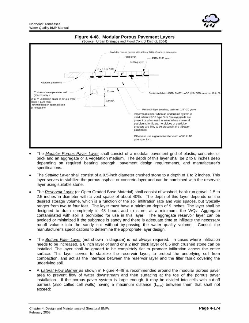
Figure 4-48. Modular Porous Pavement Layers (Source: Urban Drainage and Flood Control District, 2004)
Modular porous pavers with at least 20% of surface area open
Filter layer
Settling layer
S = 0.0 to 2.0%
ASTM C-33 sand
6" min.
12" min.
6" wide concrete perimeter wall( if necessary )
Adjacent pavement
3" or 4" underdrain space at 20' o.c. (max)slope = 1.0% (min) for infiltration on apporiate soils(if necessary)
Geotextile fabric: ASTM D 4751- AOS U.S> STD sieve no. 40 to 60
Reservoir layer (washed, bank run (1.5" -2") gravel
Impermeable liner when an underdrain system isused, when NRCS type D or C (clayey)soils arepresent or when used in areas where chemical,petroleum, fertilizers, herbicides or pesticideproducts are likey to be present in the tributarycatchment.
Otherwise use a geotextile filter cloth w/ 60 to 80pores per inch.
• The Modular Porous Paver Layer shall consist of a modular pavement grid of plastic, concrete, or
brick and an aggregate or a vegetation medium. The depth of this layer shall be 2 to 8 inches deep depending on required bearing strength, pavement design requirements, and manufacturer’s specifications.
• The Settling Layer shall consist of a 0.5-inch diameter crushed stone to a depth of 1 to 2 inches. This layer serves to stabilize the porous asphalt or concrete layer and can be combined with the reservoir layer using suitable stone.
• The Reservoir Layer (or Open Graded Base Material) shall consist of washed, bank-run gravel, 1.5 to 2.5 inches in diameter with a void space of about 40%. The depth of this layer depends on the desired storage volume, which is a function of the soil infiltration rate and void spaces, but typically ranges from two to four feet. The layer must have a minimum depth of 9 inches. The layer shall be designed to drain completely in 48 hours and to store, at a minimum, the WQv. Aggregate contaminated with soil is prohibited for use in this layer. The aggregate reservoir layer can be avoided or minimized if the subgrade is sandy and there is adequate time to infiltrate the necessary runoff volume into the sandy soil without by-passing the water quality volume. Consult the manufacturer’s specifications to determine the appropriate layer design.
• The Bottom Filter Layer (not shown in diagram) is not always required. In cases where infiltration
needs to be increased, a 6 inch layer of sand or a 2 inch thick layer of 0.5 inch crushed stone can be installed. The layer shall be graded to be completely flat to promote infiltration across the entire surface. This layer serves to stabilize the reservoir layer, to protect the underlying soil from compaction, and act as the interface between the reservoir layer and the filter fabric covering the underlying soil.
• A Lateral Flow Barrier as shown in Figure 4-49 is recommended around the modular porous paver area to prevent flow of water downstream and then surfacing at the toe of the porous paver installation. If the porous paver system is large enough, it may be divided into cells with cut-off barriers (also called cell walls) having a maximum distance (Lmax) between them that shall not exceed:
Chapter 4: Design and Maintenance of Structural BMPs Page 4-174 February 2008
Northeast Tennessee Water Quality BMP Manual
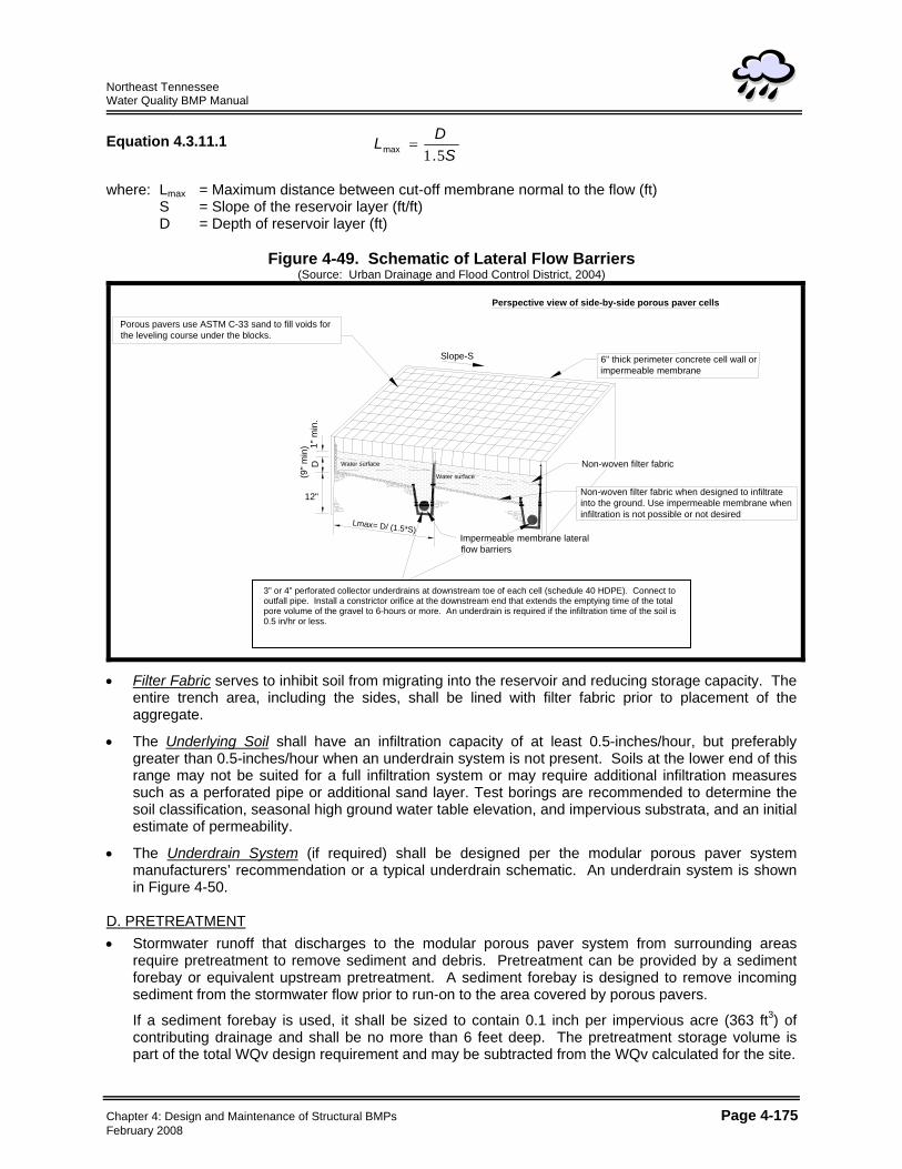
Equation 4.3.11.1 S
DL51.max =
where: Lmax = Maximum distance between cut-off membrane normal to the flow (ft) S = Slope of the reservoir layer (ft/ft) D = Depth of reservoir layer (ft)
Figure 4-49. Schematic of Lateral Flow Barriers (Source: Urban Drainage and Flood Control District, 2004)
Perspective view of side-by-side porous paver cells
Porous pavers use ASTM C-33 sand to fill voids forthe leveling course under the blocks.
Non-woven filter fabric
6" thick perimeter concrete cell wall or impermeable membrane
Slope-S
Impermeable membrane lateralflow barriers
Water surface
Water surface
3" or 4" perforated collector underdrains at downstream toe of each cell (schedule 40 PVC or HDPE)Connect to outfall pipe. Install a constrictor orifice at the downstream end (see figure 4.3.11CC)that extends the emptying time of the total pore volume of the gravel to 6-hours or more. Use underdrain only with type D or C soils or when infiltration is not desired due to potential for groundwatercontamination.
Non-woven filter fabric when designed to infiltrateinto the ground. Use impermeable membrane wheninfiltration is not possible or not desired
Lmax= D/ (1.5*S)
12"
(9" m
in)
D
1 " m
in.
3” or 4” perforated collector underdrains at downstream toe of each cell (schedule 40 HDPE). Connect to outfall pipe. Install a constrictor orifice at the downstream end that extends the emptying time of the total pore volume of the gravel to 6-hours or more. An underdrain is required if the infiltration time of the soil is 0.5 in/hr or less.
• Filter Fabric serves to inhibit soil from migrating into the reservoir and reducing storage capacity. The
entire trench area, including the sides, shall be lined with filter fabric prior to placement of the aggregate.
• The Underlying Soil shall have an infiltration capacity of at least 0.5-inches/hour, but preferably greater than 0.5-inches/hour when an underdrain system is not present. Soils at the lower end of this range may not be suited for a full infiltration system or may require additional infiltration measures such as a perforated pipe or additional sand layer. Test borings are recommended to determine the soil classification, seasonal high ground water table elevation, and impervious substrata, and an initial estimate of permeability.
• The Underdrain System (if required) shall be designed per the modular porous paver system manufacturers’ recommendation or a typical underdrain schematic. An underdrain system is shown in Figure 4-50.
D. PRETREATMENT • Stormwater runoff that discharges to the modular porous paver system from surrounding areas
require pretreatment to remove sediment and debris. Pretreatment can be provided by a sediment forebay or equivalent upstream pretreatment. A sediment forebay is designed to remove incoming sediment from the stormwater flow prior to run-on to the area covered by porous pavers.
If a sediment forebay is used, it shall be sized to contain 0.1 inch per impervious acre (363 ft3) of contributing drainage and shall be no more than 6 feet deep. The pretreatment storage volume is part of the total WQv design requirement and may be subtracted from the WQv calculated for the site.
Chapter 4: Design and Maintenance of Structural BMPs Page 4-175 February 2008
Northeast Tennessee Water Quality BMP Manual
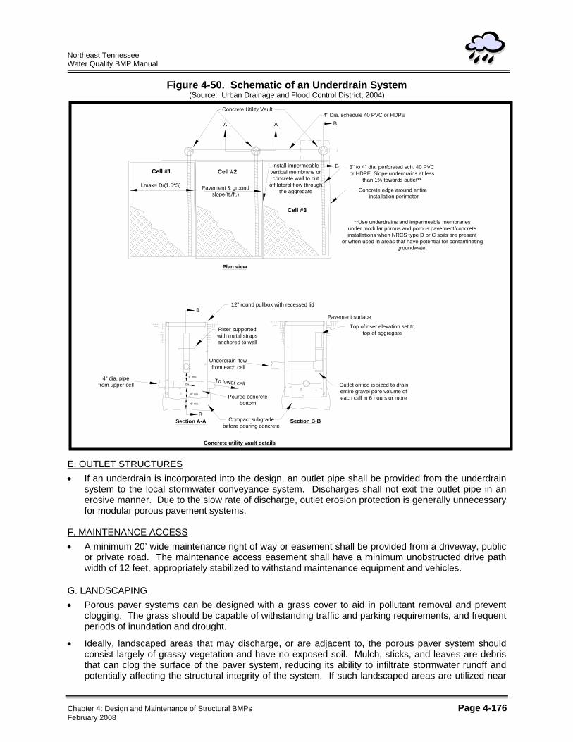
Figure 4-50. Schematic of an Underdrain System (Source: Urban Drainage and Flood Control District, 2004)
Concrete Utility Vault
A A
4" Dia. schedule 40 PVC or HDPE
Lmax= D/(1.5*S) Pavement & groundslope(ft./ft.)
Install impermeablevertical membrane orconcrete wall to cut
off lateral flow throughthe aggregate
Cell #3
Cell #2Cell #1
B
3" to 4" dia. perforated sch. 40 PVCor HDPE. Slope underdrains at less
than 1% towards outlet**
Concrete edge around entire installation perimeter
**Use underdrains and impermeable membranesunder modular porous and porous pavement/concreteinstallations when NRCS type D or C soils are present
or when used in areas that have potential for contaminatinggroundwater
Top of riser elevation set to top of aggregate
Outlet orifice is sized to drainentire gravel pore volume ofeach cell in 6 hours or more
Compact subgrade before pouring concrete
Poured concretebottom
To lower cell
Underdrain flowfrom each cell
Riser supportedwith metal straps anchored to wall
12" round pullbox with recessed lid
Pavement surface
4" dia. pipe from upper cell
Section A-A Section B-B
6" min.
6" min.
2%
4" min.
B
B
B
Plan view
Concrete utility vault details
E. OUTLET STRUCTURES • If an underdrain is incorporated into the design, an outlet pipe shall be provided from the underdrain
system to the local stormwater conveyance system. Discharges shall not exit the outlet pipe in an erosive manner. Due to the slow rate of discharge, outlet erosion protection is generally unnecessary for modular porous pavement systems.
F. MAINTENANCE ACCESS • A minimum 20’ wide maintenance right of way or easement shall be provided from a driveway, public
or private road. The maintenance access easement shall have a minimum unobstructed drive path width of 12 feet, appropriately stabilized to withstand maintenance equipment and vehicles.
G. LANDSCAPING • Porous paver systems can be designed with a grass cover to aid in pollutant removal and prevent
clogging. The grass should be capable of withstanding traffic and parking requirements, and frequent periods of inundation and drought.
• Ideally, landscaped areas that may discharge, or are adjacent to, the porous paver system should consist largely of grassy vegetation and have no exposed soil. Mulch, sticks, and leaves are debris that can clog the surface of the paver system, reducing its ability to infiltrate stormwater runoff and potentially affecting the structural integrity of the system. If such landscaped areas are utilized near
Chapter 4: Design and Maintenance of Structural BMPs Page 4-176 February 2008
Northeast Tennessee Water Quality BMP Manual
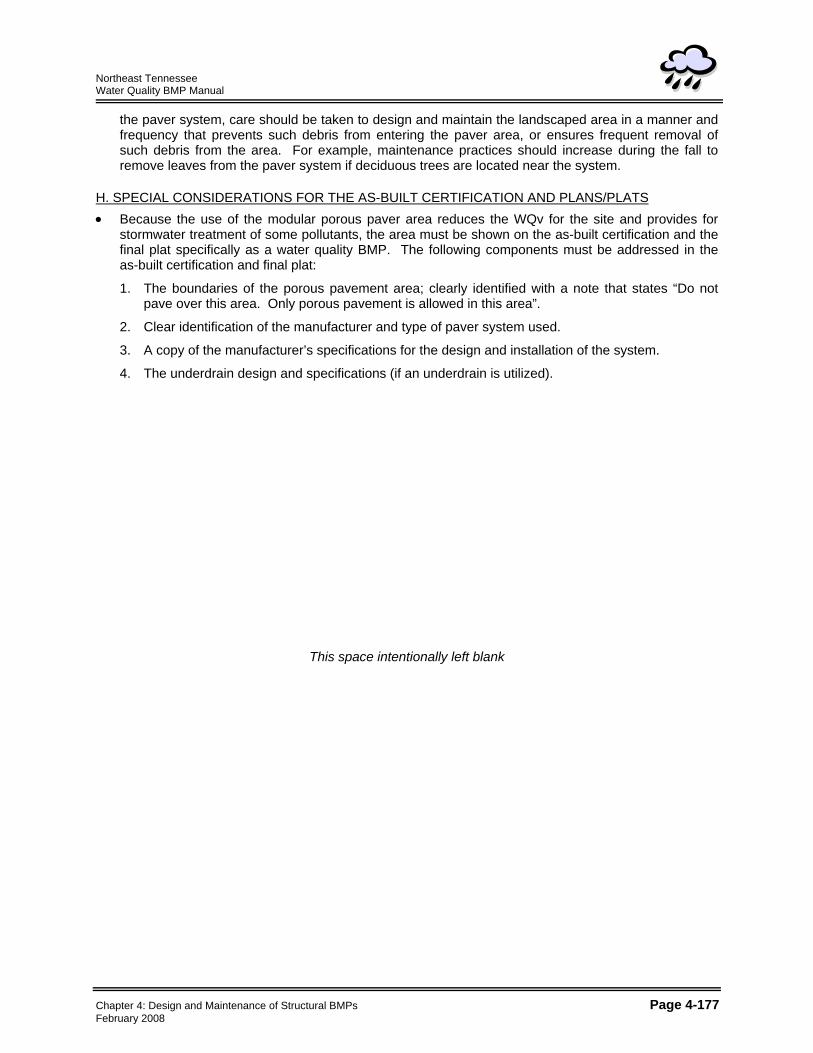
the paver system, care should be taken to design and maintain the landscaped area in a manner and frequency that prevents such debris from entering the paver area, or ensures frequent removal of such debris from the area. For example, maintenance practices should increase during the fall to remove leaves from the paver system if deciduous trees are located near the system.
H. SPECIAL CONSIDERATIONS FOR THE AS-BUILT CERTIFICATION AND PLANS/PLATS • Because the use of the modular porous paver area reduces the WQv for the site and provides for
stormwater treatment of some pollutants, the area must be shown on the as-built certification and the final plat specifically as a water quality BMP. The following components must be addressed in the as-built certification and final plat:
1. The boundaries of the porous pavement area; clearly identified with a note that states “Do not pave over this area. Only porous pavement is allowed in this area”.
2. Clear identification of the manufacturer and type of paver system used.
3. A copy of the manufacturer’s specifications for the design and installation of the system.
4. The underdrain design and specifications (if an underdrain is utilized).
This space intentionally left blank
Chapter 4: Design and Maintenance of Structural BMPs Page 4-177 February 2008

Northeast Tennessee Water Quality BMP Manual
This page left intentionally blank
Chapter 4: Design and Maintenance of Structural BMPs Page 4-178 February 2008
Northeast Tennessee Water Quality BMP Manual
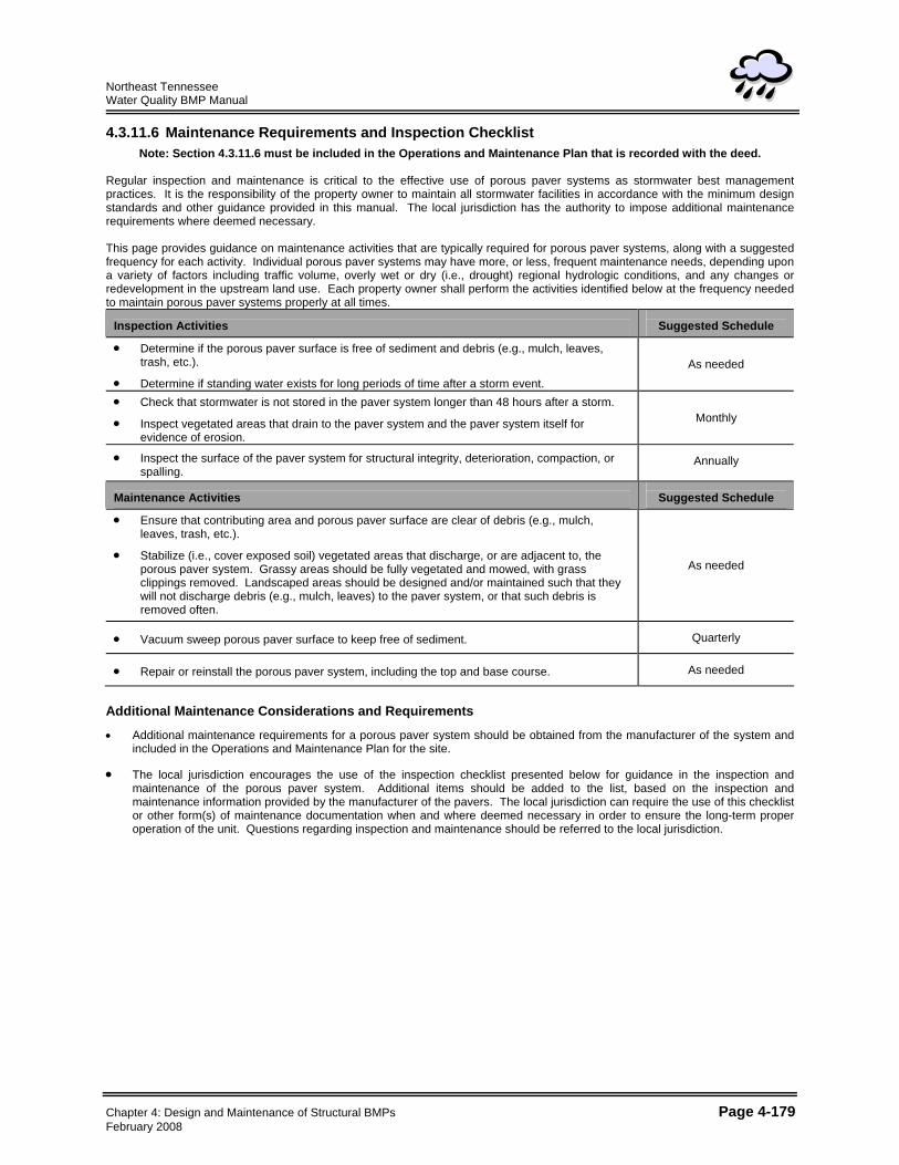
4.3.11.6 Maintenance Requirements and Inspection Checklist Note: Section 4.3.11.6 must be included in the Operations and Maintenance Plan that is recorded with the deed.
Regular inspection and maintenance is critical to the effective use of porous paver systems as stormwater best management practices. It is the responsibility of the property owner to maintain all stormwater facilities in accordance with the minimum design standards and other guidance provided in this manual. The local jurisdiction has the authority to impose additional maintenance requirements where deemed necessary. This page provides guidance on maintenance activities that are typically required for porous paver systems, along with a suggested frequency for each activity. Individual porous paver systems may have more, or less, frequent maintenance needs, depending upon a variety of factors including traffic volume, overly wet or dry (i.e., drought) regional hydrologic conditions, and any changes or redevelopment in the upstream land use. Each property owner shall perform the activities identified below at the frequency needed to maintain porous paver systems properly at all times.
Inspection Activities
Suggested Schedule
• Determine if the porous paver surface is free of sediment and debris (e.g., mulch, leaves, trash, etc.).
• Determine if standing water exists for long periods of time after a storm event. As needed
• Check that stormwater is not stored in the paver system longer than 48 hours after a storm.
• Inspect vegetated areas that drain to the paver system and the paver system itself for evidence of erosion.
Monthly
• Inspect the surface of the paver system for structural integrity, deterioration, compaction, or spalling.
Annually
Maintenance Activities
Suggested Schedule
• Ensure that contributing area and porous paver surface are clear of debris (e.g., mulch, leaves, trash, etc.).
• Stabilize (i.e., cover exposed soil) vegetated areas that discharge, or are adjacent to, the porous paver system. Grassy areas should be fully vegetated and mowed, with grass clippings removed. Landscaped areas should be designed and/or maintained such that they will not discharge debris (e.g., mulch, leaves) to the paver system, or that such debris is removed often.
As needed
• Vacuum sweep porous paver surface to keep free of sediment. Quarterly
• Repair or reinstall the porous paver system, including the top and base course. As needed
Additional Maintenance Considerations and Requirements
• Additional maintenance requirements for a porous paver system should be obtained from the manufacturer of the system and included in the Operations and Maintenance Plan for the site.
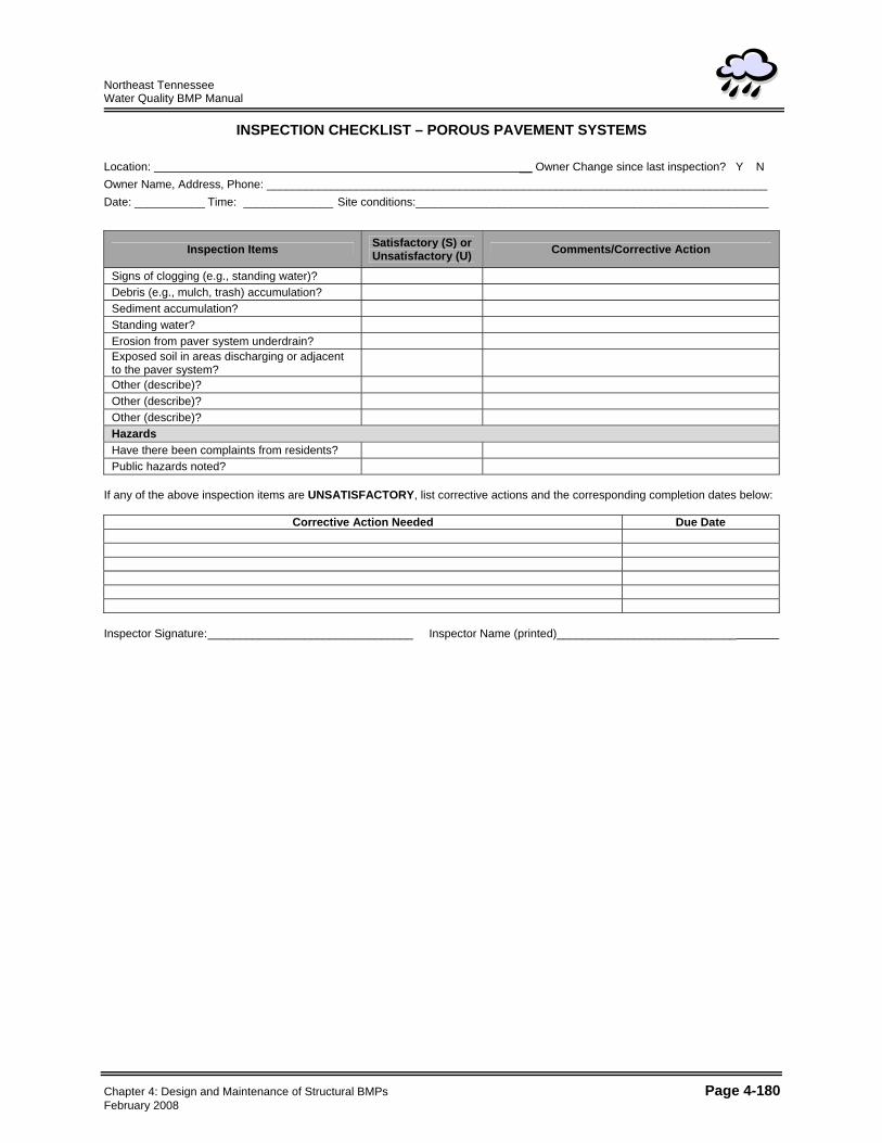
• The local jurisdiction encourages the use of the inspection checklist presented below for guidance in the inspection and maintenance of the porous paver system. Additional items should be added to the list, based on the inspection and maintenance information provided by the manufacturer of the pavers. The local jurisdiction can require the use of this checklist or other form(s) of maintenance documentation when and where deemed necessary in order to ensure the long-term proper operation of the unit. Questions regarding inspection and maintenance should be referred to the local jurisdiction.
Chapter 4: Design and Maintenance of Structural BMPs Page 4-179 February 2008
Northeast Tennessee Water Quality BMP Manual
INSPECTION CHECKLIST – POROUS PAVEMENT SYSTEMS Location: __ Owner Change since last inspection? Y N Owner Name, Address, Phone: ______________________________________________________________________________ Date: ___________ Time: ______________ Site conditions:_______________________________________________________
Inspection Items Satisfactory (S) or Unsatisfactory (U) Comments/Corrective Action
Signs of clogging (e.g., standing water)? Debris (e.g., mulch, trash) accumulation? Sediment accumulation? Standing water? Erosion from paver system underdrain? Exposed soil in areas discharging or adjacent to the paver system?
Other (describe)? Other (describe)? Other (describe)? Hazards Have there been complaints from residents? Public hazards noted?
If any of the above inspection items are UNSATISFACTORY, list corrective actions and the corresponding completion dates below:
Corrective Action Needed Due Date
Inspector Signature: ________________________________ Inspector Name (printed)____________________________
Chapter 4: Design and Maintenance of Structural BMPs Page 4-180 February 2008
Northeast Tennessee Water Quality BMP Manual
4.3.11.7 References Atlanta Regional Council (ARC). Georgia Stormwater Management Manual Volume 2 Technical
Handbook. 2001. City of Knoxville. Knoxville Best Management Practices Manual. City of Knoxville Stormwater Engineering
Division, March 2003. City of Nashville, Tennessee. Metropolitan Nashville and Davidson County Stormwater Management
Manual, Volume 4 Best Management Practices. 2006. Knox County, Tennessee. Knox County Stormwater Management Manual Volume 2, Technical
Guidance. 2006. Metropolitan Council. Minnesota Urban Small Sites BMP Manual. Metropolitan Council Services, St.
Paul Minnesota, 2001. Urban Drainage and Flood Control District, Denver, Colorado. Urban Storm Drainage Criteria Manual –
Volume 3 – Best Management Practices – Stormwater Quality. 2004 4.3.11.8 Suggested Reading California Storm Water Quality Task Force. California Storm Water Best Management Practice Handbooks.
1993. US EPA. Storm Water Technology Fact Sheet: Modular Treatment Systems. EPA 832-F-99-044, Office
of Water, 1999.
Chapter 4: Design and Maintenance of Structural BMPs Page 4-181 February 2008

Northeast Tennessee Water Quality BMP Manual
This page left intentionally blank
Chapter 4: Design and Maintenance of Structural BMPs Page 4-182 February 2008