Embed Size (px)
Citation preview

42 IEEE TRANSACTIONS ON INTELLIGENT TRANSPORTATION SYSTEMS, VOL. 5, NO. 1, MARCH 2004
Automatic License Plate RecognitionShyang-Lih Chang, Li-Shien Chen, Yun-Chung Chung, and Sei-Wan Chen, Senior Member, IEEE
Abstract—Automatic license plate recognition (LPR) playsan important role in numerous applications and a number oftechniques have been proposed. However, most of them workedunder restricted conditions, such as fixed illumination, limitedvehicle speed, designated routes, and stationary backgrounds. Inthis study, as few constraints as possible on the working environ-ment are considered. The proposed LPR technique consists oftwo main modules: a license plate locating module and a licensenumber identification module. The former characterized by fuzzydisciplines attempts to extract license plates from an input image,while the latter conceptualized in terms of neural subjects aims toidentify the number present in a license plate. Experiments havebeen conducted for the respective modules. In the experiment onlocating license plates, 1088 images taken from various scenesand under different conditions were employed. Of which, 23images have been failed to locate the license plates present inthe images; the license plate location rate of success is 97.9%. Inthe experiment on identifying license number, 1065 images, fromwhich license plates have been successfully located, were used.Of which, 47 images have been failed to identify the numbers ofthe license plates located in the images; the identification rate ofsuccess is 95.6%. Combining the above two rates, the overall rateof success for our LPR algorithm is 93.7%.
Index Terms—Color edge detector, fuzzification, licensenumber identification, license plate locating, license plate recog-nition (LPR), self-organizing (SO) character recognition, springmodel, topological sorting, two-stage fuzzy aggregation.
I. INTRODUCTION
AUTOMATIC license plate recognition (LPR) plays an im-portant role in numerous applications such as unattended
parking lots [31], [35], security control of restricted areas [8],traffic law enforcement [7], [33], congestion pricing [5], andautomatic toll collection [20]. Due to different working envi-ronments, LPR techniques vary from application to application.Most previous works have in some way restricted their workingconditions [9], such as limiting them to indoor scenes, stationarybackgrounds [30], fixed illumination [7], prescribed driveways[22], [26], limited vehicle speeds [1], or designated ranges ofthe distance between camera and vehicle [23]. The aim of thisstudy is to lessen many of these restrictions.
Of the various working conditions, outdoor scenes and non-stationary backgrounds may be the two factors that most influ-
Manuscript received December 11, 2002; revised December 8, 2003. Thiswork was supported by the National Science Council, Republic of China,under Contract NSC-89-2218-E-003-002. The Associate Editor for this paperwas A. Broggi.
S.-L. Chang, L.-S. Chen, and Y.-C. Chung are with the Department of Infor-mation and Computer Education, National Taiwan Normal University, Taipei,Taiwan, R.O.C.
S.-W. Chen is with the Graduate Institute of Computer Science and Informa-tion Engineering, National Taiwan Normal University, Taipei, Taiwan, R.O.C.(e-mail: [email protected]).
Digital Object Identifier 10.1109/TITS.2004.825086
ence the quality of scene images acquired and in turn the com-plexity of the techniques needed. In an outdoor environment, il-lumination not only changes slowly as daytime progresses, butmay change rapidly due to changing weather conditions andpassing objects (e.g., cars, airplanes, clouds, and overpasses).In addition, pointable cameras create dynamic scenes when theymove, pan or zoom. A dynamic scene image may contain mul-tiple license plates or no license plate at all. Moreover, whenthey do appear in an image, license plates may have arbitrarysizes, orientations and positions. And, if complex backgroundsare involved, detecting license plates can become quite a chal-lenge.
Typically, an LPR process consists of two main stages: 1)locating license plates and 2) identifying license numbers. In thefirst stage, license plate candidates are determined based on thefeatures of license plates. Features commonly employed havebeen derived from the license plate format and the alphanumericcharacters constituting license numbers. The features regardinglicense plate format include shape, symmetry [15], height-to-width ratio [23], [25], color [17], [25], texture of grayness [2],[25], spatial frequency [26], and variance of intensity values [8],[10]. Character features include line [34], blob [13], the signtransition of gradient magnitudes, the aspect ratio of characters[12], the distribution of intervals between characters [28], andthe alignment of characters [32]. In reality, a small set of robust,reliable, and easy-to-detect object features would be adequate.
The license plate candidates determined in the locating stageare examined in the license number identification stage. Thereare two major tasks involved in the identification stage, char-acter separation and character recognition. Character separationhas in the past been accomplished by such techniques as projec-tion [11], [30], morphology [2], [10], [28] relaxation labeling,connected components [25], and blob coloring. Every techniquehas its own advantages and disadvantages. Since the projectionmethod assumes the orientation of a license plate is known andthe morphology method requires knowing the sizes of charac-ters, these two approaches are not appropriate for our applica-tion because of their required assumptions. Relaxation labelingis by nature iterative and often time consuming. In this study, ahybrid of connected components and blob coloring techniquesis considered for character separation.
There have been a large number of character recognition tech-niques reported. They include genetic algorithms [17], artifi-cial neural networks [2], [16], [26], fuzzy c-means [25], supportvector machine [16], Markov processes [6], and finite automata[1]. These methods can be broadly classified into iterative andnoniterative approaches. There is a tradeoff between these twogroups of approaches; iterative methods achieve better accuracy,but at the cost of increased time complexity. In this study, wepay more attention to accuracy than time complexity whenever
1524-9050/04$20.00 © 2004 IEEE

CHANG et al. AUTOMATIC LICENSE PLATE RECOGNITION 43
TABLE ISTYLES OF LICENSE PLATES UNDER CONSIDERATION
a choice has to be made between them. For this, we developedour own character recognition technique, which is based on thedisciplines of both artificial neural networks and mechanics.
The rest of this paper is organized as follows. In Section II,the types of license plates to be considered are described, fol-lowed by the fundamental idea of the proposed LPR technique.The two primary stages of the proposed technique, license platelocation and license number identification, are discussed in de-tail in Sections III and IV, respectively. Experimental results arepresented in Section V. Concluding remarks and ideas for futurework are given in Section VI.
II. LPR
In this section, the styles of license plate that are consideredin this study are discussed, followed by a brief description of theproposed LPR process. Table I shows assorted styles of licenseplates found on vehicles in Taiwan. Each style is associated witha particular class of vehicle. The classes include private auto-mobile, taxi, tour bus, truck, and government vehicles. Othercategories of vehicles, such as diplomatic cars and military ve-hicles, are not addressed since they are rarely seen. Styles of li-cense plates can easily be distinguished based on two attributes:1) the combination of colors used and 2) the compositional se-mantics of license numbers.
As shown in Table I, each style has a different foregroundand/or background color. However, in all only four distinctcolors (white, black, red, and green) are utilized in theselicense plates. We shall pay attention to these four colorswhen searching for license plates in an input image. The com-positional semantics of license numbers provides additionalinformation for differentiating styles of license plates. As canbe seen in Table I, every license number is composed of twoparts separated by a hyphen (e.g., E1-2345). The first partconsists of two characters, one of which must be an alphabeticalcharacter (e.g., E1, 2F, and EF). The second part may containfour (e.g., 2345) or three (e.g., 234) numerals, the former beingused only on private automobiles, and the latter being used onthe other vehicle classes.
Fig. 1 shows the proposed LPR process. We assume that theprocess is incorporated in an event detection system, e.g., a ve-hicle detector or a traffic law enforcement system. Once thesystem detects an event, the camera along with the system isactivated. The image acquired by the camera is then sent tothe LPR process, in which potential license plates are extractedfrom the image. If no license plate is found, the process returnsto await another input image. However, oftentimes multiple li-cense plate candidates are detected. They are closely examined
Fig. 1. Diagram of the proposed LPR process.
at the license number identification stage. There are two es-sential tasks involved in this stage, character segmentation andrecognition. These two tasks are alternatively invoked in orderto achieve optimal results for both segmentation and recogni-tion. The characters recovered from a license plate candidate atthis stage are next verified at the confirmation stage. The groupof characters will be deemed to form a valid license number ifit agrees with the compositional semantics of license numbersmentioned earlier. Both the valid license number and the asso-ciated vehicle class will be returned by the LPR process. Theidentification and confirmation stages repeat for all of the li-cense plate candidates. Afterwards, the process returns to awaitanother input image.
In Sections III and IV, we look at the details of the licenseplate locating module and the license number identificationmodule.
III. LICENSE PLATE LOCATING MODULE
A. Basic Concepts
A flowchart for the license plate locating module is shownin Fig. 2. The input to this module is an RGB color image. Re-call that only four colors (white, black, red, and green) are uti-lized in the license plates that we consider. Note also that thereare many edges, which are in close mutual proximity and aredispersed in a repetitive manner, contained in a license plate.The above observations motivates us to develop a color edge de-tector. The edge detector is sensitive to only three kinds of edges,black-white, red-white, and green-white (see the last column ofTable I). By ignoring other types of edges in an image, very fewedges due to objects other than license plates are detected, even

44 IEEE TRANSACTIONS ON INTELLIGENT TRANSPORTATION SYSTEMS, VOL. 5, NO. 1, MARCH 2004
Fig. 2. Flowchart for the license plate locating module.
when the image background is very cluttered. Let denote theedge map computed from the input image using the color edgedetector.
Next, the RGB space of the input color image is transformedinto the HSI space. Let and denote the (red,green, blue) and (hue, saturation, intensity) values of an imagepixel, respectively. The transform from to[3] is
(1)
where , and . There area number of intriguing characteristics associated with the HSIcolor model which are useful for our application, including theinvariance of hue to both illumination and shading, and the in-variance of saturation to both viewing direction and surface ori-entation. Let , , and be the maps preserving the hue, satu-ration, and intensity components of the transformed image, re-spectively.
It is inevitable that maps , , , and are less than perfectin view of noise, measurement error, and imperfect processing.In order to compensate for this drawback, we appeal to the softcomputing techniques rooted in fuzzy (for license plate loca-tion) and neural (for license number identification) disciplines.Let , , , and be the fuzzy versions of , , , and . The
entries in the fuzzy maps represent the degrees of belonging to alicense plate. A two-stage fuzzy aggregator is introduced to inte-grate the maps. In the first stage, fuzzy maps , , and are in-tegrated. The resulting map next combines with in the secondstage leading to a single map, denoted . The reason of usingthe two-stage aggregator is because the intrinsic characteristics(related to color) of , , and are different from that (related toedge magnitude) of . Afterwards, based on map , interestingregions are located in the input image, which have locally max-imal values. License plate candidates are then determined tobe those interesting areas whose sizes are large enough.
B. Color Edge Detection
The color edge detector focuses on only three kinds of edges(i.e., black-white, red-white and green-white edges). Consider ablack-white edge, and suppose that the input RGB color imagehas been normalized into an image. Ideally, thevalues of a white pixel and a black pixel should beand , respectively. Their differences areeither or , so all the components of thedifference vector between a white and a black pixel will havethe same sign. This property is considerably stable under envi-ronmental variations. A black-white edge pixel is then definedbased on this property as follows. An image pixel is regardedas a black-white edge point if all of the signs of components ofthe difference vector between the pixel and one of its neighborsare the same, i.e., , ,where is the set of neighbors of the image pixel. We also storeits edge magnitude defined as . Edgemagnitudes will be exploited later to derive fuzzy edge maps.

CHANG et al. AUTOMATIC LICENSE PLATE RECOGNITION 45
In a similar way, an image pixel is considered to be ared-white edge point if its difference vectorfor some satisfies the following conditions: 1)
and 2)and . The magnitude of the edge pixel isdefined as . Finally, an image pixel isregarded to be a green-white edge pixel if for some , 1)
and 2)and . Its edge magnitude is determined by
. Image pixels, which are not edge points,are given zero edge magnitudes.
C. Fuzzy Maps
The basic idea of generating a fuzzy map from a given map(e.g., , , , or ) is as follows. Since every map encodessome characteristic about the scene, the entry of any cell in themap expresses the degree of the cell possessing the property.In order to highlight the cells corresponding to the objects ofinterest (e.g., license plates), we assign large entries to thosecells that are compatible with the known characteristics of theobjects. Such large entries indicate a high degree of existence ofan interesting object. We call the resultant map the characteristicmap of the original map.
Since the input data (both the given map and the object char-acteristics) are not perfect, uncertainties should be taken into ac-count during the computation of the characteristic map. Fuzzysets have been known to provide an elegant tool for modelinguncertainties [14], [18], [27]. In this study, we introduce fuzzi-nesses into the entries of the characteristic map and refer to theresult as the fuzzy map. There are several ways to realize fuzzi-ness. We define a generalized fuzzy set, termed “like a licenseplate,” on the respective sets of hue, saturation, intensity, andedge magnitude. Each of the four sets serves as a universal setof the fuzzy set.
1) Map: Consider the universal set of hue values.Suppose that the object of interest has a color whose cor-responding hue value is . Given an entry in map , say ,the membership degree, , of the entry belonging to fuzzy set“like the object” can be written
where is a positive constant. If the given entry is equal tothat of the interesting object , then the degree of membershipis 1. As the difference between the hues increases, the degree ofmembership decreases to an asymptotic value of 0. Recall thatthere are four colors (black, white, red and green) utilized in thelicense plates that are of interest. Let and be the hue valuesfor red and green, respectively. Note that the hues of achromaticcolors (i.e., all levels of grey, including black and white) are notdefined since the denominator of the equation for hue in (1) iszero. Therefore, we will highlight red and green, but not whiteand black based on map . The membership function of fuzzymap is finally defined as
(2)
where can be any fuzzy union operator (any -conorm func-tion).
2) Map: Since fuzzy map can only express the colorsred and green, we need other means to handle black and white.According to the in (1), all achromatic colors have the samesaturation . In addition, this value is smaller than that of anychromatic color. Based on these two facts, we generate a fuzzymap from map for distinguishing between chromatic andachromatic colors. The membership function of is defined as
(3)
This states that the smaller a given saturation value the morelikely that it comes from some achromatic color.
3) Map: While chromatic and achromatic colors can beseparated from each other based on their saturation values,black and white have to be further differentiated from otherachromatic colors. For this, we count on the intensity map .Since the intensity values of black and white correspond to thetwo extreme values on the intensity axis of the HSI coordinatesystem, the following function emphasizes the colors withintensity values close to the two extremes
This assumes that the working environment has an average in-tensity of 0.5. However, both black and white will be distortedunder some circumstances. For example, a white color may ap-pear grey in a dark environment, as will a black color in a brightenvironment. To compensate for such distortion, the constant0.5 in the above equation may be replaced with the averagevalue, , of map . We then define the membership function offuzzy map as
(4)
4) Map: Based on fuzzy maps , , and image areaswith black, white, red, or green colors can be distinguished.However, a large portion of these areas has nothing to do withlicense plates. Edge maps play a crucial role in discriminatingagainst irrelevant regions. Since there are many close-by edgesin a license plate and distributed in a repetitive manner, an imagepixel whose neighbors possess large edge magnitudes will havea high possibility that it belongs to a license plate. Hence, wedefine the membership function of fuzzy edge map as
(5)
where is the horizontal neighborhood of the image pixelunder consideration, is the edge magnitude of pixel in ,and is the Euclidean distance between pixels and . In theabove function we do not care about the edge magnitude ofpixel itself.
D. Fuzzy Aggregation
Each fuzzy map provides information for locating licenseplates in the input image. There are two ways to draw a conclu-sion from a set of maps. In the first, intermediate decisions aremade on the basis of individual maps and a final conclusion isdrawn from the intermediate decisions. In the second, multiplemaps are first integrated into a single map, and a final conclusion

46 IEEE TRANSACTIONS ON INTELLIGENT TRANSPORTATION SYSTEMS, VOL. 5, NO. 1, MARCH 2004
is then drawn from the integrated map. Since the first methodinvolves both numerical computations and symbolic decisions,we prefer the second approach, which includes only numericalcomputations. Following the second approach, fuzzy maps ,
, , and are integrated into a single map, , with decisionsbeing made on the basis of . A two-stage fuzzy aggregator isintroduced for this purpose.
In the first stage of the aggregator, fuzzy maps , , andare integrated cell by cell. Let , , and be the entries of thecorresponding cells in fuzzy maps , , and . The aggregatorintegrates the entries by
(6)
where is a fuzzy union operator and , , and areweights reflecting the relative degrees of importance amongfuzzy maps , , and . The weights are described next.
Recall that in the definition of a fuzzy map a large entry in-dicates a high degree of possibility that the entry belongs toa license plate. However, if the majority of cells having smallvariations in the entry (i.e., having nearly uniform distributionof entries) are in a fuzzy map, the usefulness of the map for de-tecting license plates deteriorates. To see this, consider a picturetaken in the evening or on a rainy day. On the whole, the picturewill look dim. The overall intensities of image pixels tend to besmall, which in turn leads to large saturation values throughoutthe picture [see (1)]. Both the intensity and saturation maps con-tribute little to locating license plates because entries are com-parable. In all fuzzy maps, it is desirable that a relatively smallportion of a map possesses large entries, while the remainingareas contain small values. Such a map will be given a largeweight to reflect a high degree of importance of the map. Let
be any fuzzy map of size by . Its weight (ordegree of importance) is then determined by
(7)
where
ifotherwise
in which threshold and and arethe maximum and minimum values in
After combining fuzzy maps , , and , at the second stagethe resulting map, say , and fuzzy map are linearly com-bined into by
(8)
where and are the weights of maps and , which aredetermined similar to (7).
IV. LICENSE NUMBER IDENTIFICATION MODULE
A. Fundamental Idea
Fig. 3 gives the flowchart for the identification module.There are two major components constituting the module,
Fig. 3. Flowchart for the license number identification module.
preprocessing and recognition. The preprocessing componentconsists of three tasks, binarization, connected componentlabelling, and noise removal, which are arranged in sequence.The recognition component is composed of two main pro-cedures, character segmentation and recognition. To obtainoptimal results for both the procedures, they are alternativelyinvoked.
Since the camera may be rolled and/or pitched with respectto license plates, it is desirable that their images be transformedto a predefined size and orientation before performing licensenumber identification. However, without information about re-lationships between the camera and working environments, thetransformations can only be conducted blindly or by trial-and-error. In the proposed method since the transformation step isomitted, it is inevitable that difficulties in the subsequent stepswill increase.
Considering a license plate candidate, it is first binarized.Since some information will somehow be lost during binariza-tion, a variable thresholding technique previously proposed byNakagawa and Rosenfeld [24] is employed. The technique de-termines a local optimal threshold value for each image pixelso as to avoid the problem originating from nonuniform illumi-nation. Although variable thresholding cannot completely com-pensate for the information loss mentioned above, it at leastpreserves information that may be lost when using a constantbinarization method. There are two purposes for the binariza-tion step: highlighting characters and suppressing background.However, both desired (e.g., characters) and undesired (e.g.,noise and borders of vehicle plates) image areas often appearduring binarization.

CHANG et al. AUTOMATIC LICENSE PLATE RECOGNITION 47
In order to eliminate undesired image areas, a connected com-ponent algorithm is first applied to the binarized plate candidate.The aspect ratios of connected components are then calculated.The components whose aspect ratios are outside a prescribedrange are deleted. Then an alignment of the remaining compo-nents is derived by applying the Hough transform to the centersof gravity of components. The components disagreeing with thealignment are removed. If the number of remaining componentsis still larger than a prescribed number (eight in practice), con-nected components are deleted one at a time starting with thesmallest. Here, we choose eight as the prescribed number be-cause a license number consists of five or six characters andcharacters may be broken. The removal process continues untileither of two conditions is satisfied. Either the number of re-maining components equals the prescribed number, or a dra-matic change in size from the previously removed componentto the current one under consideration is encountered. We as-sume that noise components are much smaller than characters.
The above procedure does not guarantee that each of the sur-viving components will correspond to an individual character.A component may be due to noise, an incomplete character, adistorted character, or characters that appear to touch. To dis-tinguish them, we utilize attributes of license plates, includingthe aspect ratios of individual characters, the regular intervalsbetween characters, and the number of characters constitutinglicense numbers. We refer to these attributes collectively as thestructural constraints of license plates. We also introduce the op-erators of delete, merge, split and recover into the character seg-mentation procedure. Note that characters may be missed duringlicense plate location and binarization. The recover operator isintroduced to retrieve missing characters.
During processing the segmentation procedure applies thefirst three operators (delete, merge, and split) to the set of sur-viving components in an attempt to determine if a componentsatisfies the structural constraints of license plates. If such acomponent can be determined, the character recognition proce-dure is invoked to identify a character from the component. Theabove process repeats until no character can be extracted fromthe set of surviving components. Thereafter, if the number of ex-tracted characters is less than the number of characters in licensenumbers, the recover operator starts at the outermost charactersof those detected and searches for characters along the align-ment of the known characters. The search continues until nocharacter can be retrieved within an extent determined by theaverage width of characters as well as intervals between char-acters. Next, the collection of identified characters is verified inthe confirmation stage, where the compositional semantics oflicense numbers plays an important role. The set of characterswill be deemed to form a valid license number if it agrees withthe compositional semantics.
B. Optical Character Recognition
In this subsection we discuss the character recognition pro-cedure. Since, as already mentioned, license plates may be bentand/or tilted with respect to the camera, characters extractedfrom such license plates may be deformed. Furthermore, inputcharacters may be noisy, broken or incomplete. Character recog-nition techniques should be able to tolerate these defects. In this
Fig. 4. Nodal types: (a) end-point, (b) three-way node, and (c) four-way node.
study, we develop our own character recognition approach tosuit our particular application. The proposed approach consistsof three steps: character categorization, topological sorting, andself-organizing (SO) recognition. In the first step, the input char-acter is distinguished as numerical or alphabetical. This is easilyaccomplished by referring to the compositional semantics of li-cense numbers. In the next step, the topological features of theinput character are computed and are compared with those ofprestored character templates. Compatible templates will forma test set, in which the character template that best matches theinput character is determined. The template test is performed bya SO character recognition procedure.
1) Topological Sorting: The topological features of charac-ters utilized in this study include the number of holes, end-points, three-way nodes, and four-way nodes (see Fig. 4 for theirdefinitions). These features are invariant to spatial transforma-tions (including rotation, translation and scale change). More-over, these features, which are qualitative in nature, can be easilyand reliably detected compared to quantitative features. How-ever, input characters are usually imperfect; extra or missingfeatures may occur. The following rule is employed for topo-logical sorting. A character template is compatible with a givencharacter whenever 1) their difference in the numbers of holesis within the range and 2) their difference between thenumbers of nodes of any type is within the range . Here,a smaller range is given to the hole feature because it is gener-ally more reliable in detection than nodes. In our experimentsno more than three out of ten numerical character templates andsix out of 26 alphabetical character templates have passed topo-logical sorting for any given character. This has greatly reducedthe number of templates in the test set and hence the time com-plexity for character recognition.
2) Template Test: The templates in the test set are matchedagainst the input character and the best match is determined.The template test is primarily accomplished using a SO char-acter recognition approach, which is based on Kohonen’s SOneural network [19]. The idea behind the proposed techniqueis as follows. Given an unknown character and a character tem-plate, the input character is encoded in terms of synaptic weightsin the between-layer links of the neural network. The charactertemplate here serves as a stimulus, which repeatedly innervatesthe neural network, causing the synaptic weights of the neuralnetwork to gradually change. This process continues until theweights stabilize. We sum up the changes of synaptic weightsduring processing. The total change in weight in a sense reflectsthe level of dissimilarity between the unknown character and thecharacter template.
Let be the set of character templates sur-viving from the topological sorting of an unknown input char-acter. Let denote the computed dissimilarities be-tween the unknown character and the character templates. It isnatural that the character template having the smallest dissim-

48 IEEE TRANSACTIONS ON INTELLIGENT TRANSPORTATION SYSTEMS, VOL. 5, NO. 1, MARCH 2004
Fig. 5. Kohonen SO neural model.
ilarity with the unknown character is taken to be the class towhich the unknown character belongs.
a) SO Neural Model: In this subsection, we brief the keycomponents of the Kohonen SO neural model, which will beused in the later practical implementation. Referring to Fig. 5,the underlying configuration of the SO neural network consistsof two layers, an input layer and an SO layer.
Let be the weight of the link between SO neuronand input neuron . The weight vector for is
, where is the number ofinput neurons. Let denote an externalstimulus. The input to due to the stimulus is
(9)
The lateral interaction among SO neurons is characterized by a“Mexican-hat” function [21], denoted , where represents aposition vector. Let be the weight of the connection betweenSO neurons and located at and , respectively. Theinput to due to lateral interaction is
(10)
where is the set of SO neurons and is theactivation of , in which to be defined is the net input to
and is the output function defined by a sigmoid function.A leakage term , which dissipates activations of SO neu-
rons once a stimulus has been removed, is introduced for everySO neuron. The net input to then sums the inputs from thestimulus, lateral interaction, and leakage
(11)
During competition among SO neurons, the winner is de-termined by . Next, the winner to-gether with its neighbors, say set , engage in a group learningprocess. During this process a neuron close to the winner willgain a high rate of learning while a neuron located far from thewinner will have a low rate of learning. The rate of learning isgoverned by the Gaussian function . The learning rule for theneurons in is then defined as
(12)
Fig. 6. SO layers: (a) 0-hole, (b) 1-hole, and (c) 2-hole SO layers.
Fig. 7. Example of SO character recognition.
Finally, the updating equation for SO neuron is
(13)
where is the step size, which decreases monotonically withincreasing .
b) Practical Implementation: To begin, we group char-acters into three categories, referred to as 0-hole, 1-hole, and2-hole, according to the number of holes contained in the char-acters. Each category has its own associated SO neural network,which contains 40 SO neurons and two input neurons. The dif-ference among the three neural networks is primarily in theirconfigurations of SO layer (see Fig. 6).
Referring to the example shown in Fig. 7, suppose that we aregiven an unknown character (“C” in this example). The char-acter is normalized in size (16 by 16 pixels) in order to be con-sistent with the character templates. The number of holes in thecharacter is computed. Here, we always choose the neural net-work according to the computed number regardless of whetherthe computed number is the true number of holes for that char-acter. Since the input character (“C”) has no hole, the neural net-work with the 0-hole SO layer is chosen. Next, the contour andits length of the unknown character are found. The length is di-vided into 40 approximately equally spaced intervals. Startingat any arbitrary point along the contour, the two dimensional

CHANG et al. AUTOMATIC LICENSE PLATE RECOGNITION 49
Fig. 8. Spring model.
(2-D) position vectors, i.e., the (row, column) coordinates, ofthe 40 interval boundaries are extracted. See the right side ofFig. 7. We choose 40 points because they are about half the av-erage number of contour points in the character templates. Theposition vectors of the 40 contour points are then assigned, oneby one in the order of extraction, to the weight vectors of the40 SO neurons of the chosen neural network. Note that sinceall the configurations of SO layer of the three neural networksare symmetrical which SO neuron should be assigned first is notimportant.
Consider a 2-D space with axes corresponding to the twocomponents of weight vectors of SO neurons. The weight vectorof each SO neuron can be represented as a point in the space.This space is referred to as the weight space of the neural net-work. Since the weight vectors of SO neurons are set to the po-sition vectors of contour points of the input character, the con-tour will be recreated in the weight space when we represent theweight vectors of SO neurons as points in the weight space. Seethe picture on the right hand side of Fig. 7.
Suppose that a template (“L” in the example) chosen from thetest set for the input character is to be matched against the char-acter. Rather than the entire template, just its contour serves asthe stimulating pattern, which repeatedly innervates the neuralnetwork until its synaptic weights stabilize. In our implementa-tion the contour points are fed into the input layer of neural net-work one at a time. Consider an input contour stimulus point .The SO neurons of the network compete for the stimulus. Thewinner is determined by ,where ’s are the weight vectors of the 40 SO neurons. Thewinner and its first- and second-order neighbors, call them set
, join in the following learning process
(14)
Note that in (12) has been replaced by in (14).The is computed as follows. We use a model, called thespring model, taken from [4], in which SO neurons are assumedbeing connected with springs. The elastic spring coefficientsare simulated with synaptic weights between neurons. Refer-ring to Fig. 8, we denote the SO neurons with their weight vec-tors. Weight vectors , , and represent SO neurons
, , and , respectively, where is any learner inand and are the two first-order neighbors of .
The learner is connected to its two neighbors with the springs,whose coefficients are and . The point stimulus isdenoted in the figure.
Fig. 9. Some intermediate results of shape transformation. (a) 1st iteration. (b)5th iteration. (c) 10th iteration. (d) 42nd iteration.
The here serves as an attractive source, which during thelearning process attempts to pull toward it with force .However, the springs exerting forces and on tryto pull toward its neighbors and . In addition,there is a damping force, (not shown in the figure), for dissi-pating the energy in the spring model so that the entire systemwill eventually converge to an equilibrium state with an externalforce , i.e.
(15)
where
(16)
in which is the gravitational coefficient, is the dampingcoefficient, is the natural length of the springs, and is a smallvalue to prevent from becoming infinite as approaches .Substituting the forces in (16) into (15) for , the displacementof neuron is
(17)
For simplicity, we assume that the initial velocity of neuron ,, is zero, the neural mass is one, and the time interval
is one. The result is
(18)
Note that the calculated displacement has to be modified bythe degree of learning of neuron , , and a learningstep . The actual displacement of neuron in the weightspace is .
Accumulating the displacements of all the neurons in ac-complishes the innervation of point stimulus . Repeating theabove process for all point stimuli of the input stimulus pat-tern completes one iteration for the pattern. Iterating continuesuntil no significant displacement of SO neuron is observed (i.e.,stabilized). The total displacement of SO neurons serves as ameasure of dissimilarity between the unknown character andthe character template. Fig. 9 illustrates some intermediate re-sults of shape transformation from “C” to “L” during iteration.In this example the total displacement of neurons amounts to147 pixels. Empirically, displacements have been distributed

50 IEEE TRANSACTIONS ON INTELLIGENT TRANSPORTATION SYSTEMS, VOL. 5, NO. 1, MARCH 2004
Fig. 10. Distinguishing parts of ambiguous characters.
over the interval when correct templates were chosenfor testing.
c) Remarks: The proposed character recognition ap-proach has difficulty distinguishing character pairs (8, B) and(O, D) especially when they are distorted. To overcome this,we predefine an ambiguity set containing the characters 0, 8, Band D. For each character in the set, the nonambiguous partsof the character are specified (see Fig. 10). During characterrecognition, once an unknown character is classed as one of thecharacters in the ambiguity set, an additional minor comparisonbetween the unknown character and the classed character isperformed. The comparison focuses on only the nonambiguousparts of the character.
Our character recognition method gives different measure-ments of dissimilarity for the same character with different tiltangles with respect to the camera. Currently, this issue has nottroubled us because the characters extracted from the images oflicense plates are all in a nearly upright position. But, we mayimprove our algorithm to deal with this by introducing a nor-malization step to transform license plates into a prescribed ori-entation prior to license number identification.
V. EXPERIMENTAL RESULTS
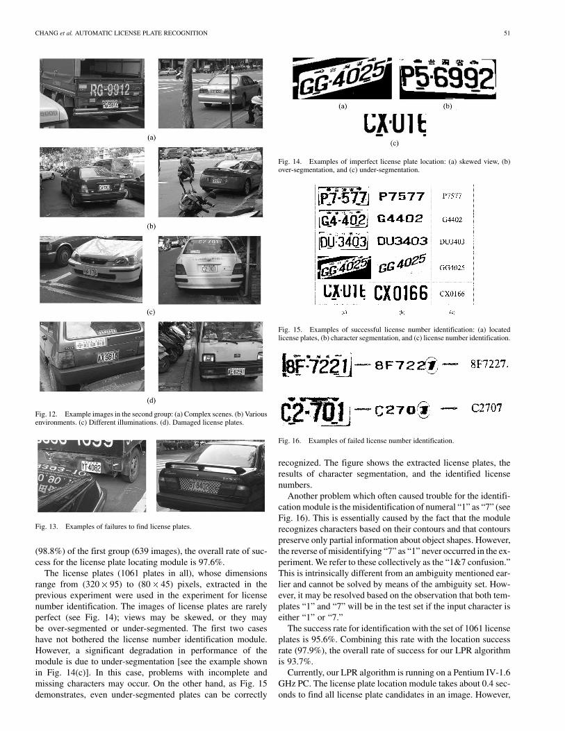
Two groups of images have been collected for our experi-ments. The first contains 639 images (640 by 480 pixels) takenfrom 71 cars of different classes. For each car, nine images wereacquired from fixed viewpoints whose positions are illustratedin Fig. 11(a). Fig. 11(b) shows two images of one car takenfrom viewpoints and . The experimental results with thefirst group of images are summarized in Table II. In this tablecolumns correspond to viewpoints, rows to the classes of vehicle(or the types of license plate), and the entries are the number ofcorrectly located license plates. The percent of correctly locatedlicense plates (the success rate) is given in the bottom row ofthe table. The success rates for viewpoints , , and (i.e.,straight on) are 100%, independent of the type of license plateand viewing distance. However, as the viewing angle increasesthe success rate declines. In the worst case, viewpoints , ,and , the success rates are 97.2%, 98.6%, and 95.8%, respec-tively. The overall average success rate with the first group ofimages is 98.8%.
The second group contains 449 images (768 by 512 pixels),some of which are shown in Fig. 12. The images are takenfrom (a) complex scenes, in which several objects look likelicense plates, (b) various environments (street, roadside andparking lot), (c) different illumination (dawn, sunshine, rain,back lighting, shadow, and nighttime), and (d) damaged licenseplates (such as being bent). In these images, all the licenseplates were successfully located as shown by the boundingboxes. Fig. 13 shows two images in which our locating modulefailed to detect license plates. In the example on the left, the
Fig. 11. (a) Nine different viewpoints for the first group of images. The lengthof one step is about 60 cm. (b) Two images of a car taken from viewpoints aand c .
TABLE IIEXPERIMENTAL RESULTS WITH THE FIRST GROUP OF IMAGES
actual license plate is connected with the reflection of a licenseplate-like image on the front of another car. The area thatincludes the license plate and the reflection was not consistentwith the constraint on aspect ratio for license plates. In theexample on the right, the license plate is surrounded by aregion, which possesses features (including color and edges)resembling those of actual license plates. The whole areacontaining the license plate and the surrounding region wasregarded by the locating module as a potential license plate.However, since the aspect ratio of the area was out of range,the locating module rejected it. The above two examples areactually unusual cases that are rarely encountered.
A common failure of the locating module is the failure todetect the boundaries of license plates. This occurs when ve-hicle bodies and their license plates have similar colors. For this,boundaries of license numbers were often extracted instead ofthe entire license plates. License plate images may be kept forfurther testing if the computed aspect ratio of the rectangulararea containing the license numbers agrees with the constraint.The location success rate achieved with the second group of im-ages (449 images) is 96.7%. Combining this rate with the rate
CHANG et al. AUTOMATIC LICENSE PLATE RECOGNITION 51
Fig. 12. Example images in the second group: (a) Complex scenes. (b) Variousenvironments. (c) Different illuminations. (d). Damaged license plates.
Fig. 13. Examples of failures to find license plates.
(98.8%) of the first group (639 images), the overall rate of suc-cess for the license plate locating module is 97.6%.
The license plates (1061 plates in all), whose dimensionsrange from (320 95) to (80 45) pixels, extracted in theprevious experiment were used in the experiment for licensenumber identification. The images of license plates are rarelyperfect (see Fig. 14); views may be skewed, or they maybe over-segmented or under-segmented. The first two caseshave not bothered the license number identification module.However, a significant degradation in performance of themodule is due to under-segmentation [see the example shownin Fig. 14(c)]. In this case, problems with incomplete andmissing characters may occur. On the other hand, as Fig. 15demonstrates, even under-segmented plates can be correctly
Fig. 14. Examples of imperfect license plate location: (a) skewed view, (b)over-segmentation, and (c) under-segmentation.
Fig. 15. Examples of successful license number identification: (a) locatedlicense plates, (b) character segmentation, and (c) license number identification.
Fig. 16. Examples of failed license number identification.
recognized. The figure shows the extracted license plates, theresults of character segmentation, and the identified licensenumbers.
Another problem which often caused trouble for the identifi-cation module is the misidentification of numeral “1” as “7” (seeFig. 16). This is essentially caused by the fact that the modulerecognizes characters based on their contours and that contourspreserve only partial information about object shapes. However,the reverse of misidentifying “7” as “1” never occurred in the ex-periment. We refer to these collectively as the “1&7 confusion.”This is intrinsically different from an ambiguity mentioned ear-lier and cannot be solved by means of the ambiguity set. How-ever, it may be resolved based on the observation that both tem-plates “1” and “7” will be in the test set if the input character iseither “1” or “7.”
The success rate for identification with the set of 1061 licenseplates is 95.6%. Combining this rate with the location successrate (97.9%), the overall rate of success for our LPR algorithmis 93.7%.
Currently, our LPR algorithm is running on a Pentium IV-1.6GHz PC. The license plate location module takes about 0.4 sec-onds to find all license plate candidates in an image. However,

52 IEEE TRANSACTIONS ON INTELLIGENT TRANSPORTATION SYSTEMS, VOL. 5, NO. 1, MARCH 2004
the license number identification module takes about two sec-onds (primarily due to the neural-based OCR process runningon a sequential computer) to process one license plate candi-date. If there are multiple plate candidates located in an image,the total processing time may not be adequate for real-time ap-plications. Several things may be considered to compensate forthe high time complexity. Firstly, since the proposed techniqueassumes no prior information about license numbers, if such in-formation is available (e.g., databases of license numbers), boththe processing time and the recognition rate will improve. Sec-ondly, if parallel machines, such as transputers, n-cubes, or PCclusters, can be used, multiple license plate candidates and char-acter templates will be able to be processed in parallel. As aconsequence, the topological sorting step becomes unnecessary.Finally, some firmware components of the algorithm could bereplaced by hardware.
VI. CONCLUDING REMARKS AND FUTURE WORK
Compared to most previous work that in some way restrictedtheir working conditions, the techniques presented in this paperare much less restrictive. The proposed LPR algorithm consistsof two modules, one for locating license plates and one for iden-tifying license numbers. Soft computing techniques rooted infuzzy (for license plate location) and neural (for license numberidentification) disciplines were introduced to compensate foruncertainties caused by noise, measurement error and imper-fect processing. Although the proposed algorithm is concernedwith the license plates of one specific country, many parts inthe algorithm are readily extended to use with license plates ofother countries. Specifically, since color and edge are two fun-damental features of license plates, the color edge detector in-troduced in the locating module is readily adapted to other colorschemes by replacing the color parameters embedded in the de-tector. Since numerals and Roman letters are commonly used toform license numbers, the proposed SO OCR technique is ap-plicable to any similarly constituted license plates.
It is well known that a mixture of top-down (expecta-tion-driven) and bottom-up (data-driven) procedures oftenperform better than either in isolation. Currently, the locatingand identification modules both perform in somewhat of ahybrid top-down and bottom-up manner. Location determina-tion is guided by both the color information of license platesand the compositional semantics of license numbers, whileidentification is based on prebuilt templates and the compo-sitional semantics. A higher degree of combining top-downwith bottom-up processing may be used in some applications,such as the control of restricted or secure areas, the detectionof stolen vehicles, and the management of car pools, wherelicense information of the cars of interest can be known a priori.
In our future work, techniques for deriving intrinsic images(e.g., illumination, reflectance and depth images) from a sceneimage or a number of input images are recommended. Intrinsicimages containing only one intrinsic characteristic of the sceneare viewpoint dependent and can be of great use for many visualinferences, such as image segmentation, view-based templatematching, and object reconstruction. Recall that at the identi-fication stage we have omitted a normalization step to trans-
form extracted license plates to a prescribed size and orienta-tion. Adding this step would improve the performance of li-cense number identification. However, normalization requiresknowing the boundaries of either license plates or license num-bers. The former may be invisible if vehicle bodies and licenseplates have similar colors, while detecting boundaries of licensenumbers can be error-prone. We leave these issues to be consid-ered in future study. Furthermore, the proposed neural approachfor character recognition is basically unsupervised. In general,supervised methods can outperform unsupervised ones if richtraining sets are available. We may later investigate supervisedapproaches.
A number of strategies have been introduced to reduce thetime complexity of the proposed LPR algorithm. The coloredge detector reduces the processing time by ignoring irrelevantedges at an early stage; the topological sorter limits the set oftemplate candidates for character test at the identification stage.Obviously, there are more things that can be done to improvethe processing time. However, in order to make our techniquesapplicable to real-time applications in less restrictive workingconditions, the topics regarding replacing firmware componentswith hard-wired ones and using parallel machines should bestudied.
ACKNOWLEDGMENT
The authors gratefully acknowledge the assistance of Prof.R. R. Bailey of the National Taiwan Normal University, Taipei,Taiwan, R.O.C., for his helpful comments and for editing theEnglish of this paper.
REFERENCES
[1] G. Adorni, F. Bergenti, and S. Cagnoni, “Vehicle license plate recogni-tion by means of cellular automata,” in Proc. IEEE Int. Conf. IntelligentVehicles, 1998, pp. 689–693.
[2] M. H. T. Brugge, J. H. Stevens, J. A. G. Nijhuis, and L. Spaanenburg,“License plate recognition using DTCNNs,” in Proc. 5th IEEE Int.Workshop on Cellular Neural Networks and Their Applications, 1998,pp. 212–217.
[3] K. R. Castleman, Digital Image Processing. Englewood Cliffs, NJ:Prentice-Hall, 1996, pp. 550–554.
[4] S. W. Chen, G. C. Stockman, and K. E. Chang, “SO dynamic deforma-tion for building of 3-D models,” IEEE Trans. Neural Networks, vol. 7,pp. 374–387, June 1996.
[5] J. R. Cowell, “Syntactic pattern recognizer for vehicle identificationnumbers,” Image and Vision Comput., vol. 13, no. 1, pp. 13–19, 1995.
[6] Y. Cui and Q. Huang, “Character extraction of license plates fromvideo,” in Proc. IEEE Conf. Computer Vision and Pattern Recognition,1997, pp. 502–507.
[7] P. Davies, N. Emmott, and N. Ayland, “License plate recognitiontechnology for toll violation enforcement,” Inst. Elect. Eng. ColloquiumImage Analysis for Transport Applications, pp. 7/1–7/5, 1990.
[8] S. Draghici, “A neural network based artificial vision system for licenseplate recognition,” Int. J. Neural Systems, vol. 8, pp. 113–126, 1997.
[9] D. M. Emiris and D. E. Koulouriotis, “Automated optic recognition ofalphanumeric content in car license plates in a semi-structured environ-ment,” in Proc. Int. Conf. Image Processing, vol. 3, 2001, pp. 50–53.
[10] D. S. Gao and J. Zhou, “Car license plates detection from complexscene,” in Proc. 5th Int. Conf. Signal Processing, vol. 2, 2000, pp.1409–1414.
[11] H. A. Hegt, R. J. De la Haye, and N. A. Khan, “A high performancelicense plate recognition system,” in Proc. IEEE Int. Conf. System, Man,and Cybernetics, vol. 5, 1998, pp. 4357–4362.
[12] X. F. Hermida, F. M. Rodriguez, J. L. F. Lijo, F. P. Sande, and M. P.Iglesias, “A system for the automatic and real time recognition of VLP’s(Vehicle License Plate),” in Proc. Lecture Notes in Computer Science,1997, vol. 1311, pp. 552–558.

CHANG et al. AUTOMATIC LICENSE PLATE RECOGNITION 53
[13] H. Hontani and T. Koga, “Character extraction method without priorknowledge on size and position information,” in Proc. IEEE Int. Conf.Vehicle Electronics, 2001, pp. 67–72.
[14] J. M. Keller and R. Krishnapuram, “Fuzzy decision models in com-puter vision,” in Fuzzy Sets, Neural Networks, and Soft Computing, R.R. Yager and L. A. Zadeh, Eds. New York: Van Nostrand, 1994, pp.213–232.
[15] D. S. Kim and S. I. Chien, “Automatic car license plate extraction usingmodified generalized symmetry transform and image warping,” in Proc.IEEE Int. Symp. Industrial Electronics, vol. 3, 2001, pp. 2022–2027.
[16] K. K. Kim, K. I. Kim, J. B. Kim, and H. J. Kim, “Learning-based ap-proach for license plate recognition,” in Proc. IEEE Signal ProcessingSociety Workshop, vol. 2, 2000, pp. 614–623.
[17] S. K. Kim, D. W. Kim, and H. J. Kim, “A recognition of vehicle licenseplate using a genetic algorithm based segmentation,” in Proc. Int. Conf.Image Processing, vol. 2, 1996, pp. 661–664.
[18] G. J. Klir and B. Yuan, Fuzzy Sets and Fuzzy Logic, Theory and Appli-cations. Englewood Cliffs, NJ: Prentice-Hall, 1995.
[19] T. Kohonen, Self-Organization and Aassociative Memory. New York:Springer-Verlag, 1989.
[20] R. A. Lotufo, A. D. Morgan, and A. S. Johnson, “Automatic number-plate recognition,” Inst. Elect. Eng. Colloquium on Image Analysis forTransport Applications, pp. 6/1–6/6, 1990.
[21] D. Marr, Vision. New York: Freeman, 1982.[22] K. Miyamoto, K. Nagano, M. Tamagawa, I. Fujita, and M. Yamamoto,
“Vehicle license plate recognition by image analysis,” in Proc. Int.Conf. Industrial Electronics, Control and Instrumentation, 1991, pp.1734–1738.
[23] T. Naito, T. Tsukada, K. Yamada, K. Kozuka, and S. Yamamoto, “Ro-bust license-plate recognition method for passing vehicles under outsideenvironment,” IEEE Trans. Veh. Technol., vol. 49, pp. 2309–2319, Nov.2000.
[24] Y. Nakagawa and A. Rosenfeld, “Some experiments on variable thresh-olding,” Pattern Recognition, vol. 11, no. 3, pp. 191–204, 1979.
[25] J. A. G. Nijhuis, M. H. T. Brugge, K. A. Helmholt, J. P. W. Pluim, L.Spaanenburg, R. S. Venema, and M. A. Westenberg, “Car license platerecognition with neural networks and fuzzy logic,” in Proc. IEEE Int.Conf. Neural Networks, vol. 5, 1995, pp. 2232–2236.
[26] R. Parisi, E. D. D. Claudio, G. Lucarelli, and G. Orlandi, “Car platerecognition by neural networks and image processing,” in Proc. IEEEInt. Symp. Circuits and Systems, vol. 3, 1998, pp. 195–198.
[27] S. W. Perry, H. S. Wong, and L. Guan, Adaptive Image Processing, AComputational Intelligence Perspective. Boca Raton, FL: CRC, 2002.
[28] J. C. H. Poon, M. Ghadiali, G. M. T. Mao, and L. M. Sheung, “A robustvision system for vehicle license plate recognition using grey-scale mor-phology,” in Proc. IEEE Int. Symp. Industrial Electronics, vol. 1, 1995,pp. 394–399.
[29] H. Ritter, T. Martinetz, and K. Schulten, Neural Computation and Self-organizing Maps an Introduction. New York: Addison-Wesley, 1992.
[30] L. Salgado, J. M. Menendez, E. Rendon, and N. Garcia, “Automatic carplate detection and recognition through intelligent vision engineering,”in Proc. IEEE Int. Carnahan Conf. Security Technology, 1999, pp.71–76.
[31] T. Sirithinaphong and K. Chamnongthai, “The recognition of car licenseplate for automatic parking system,” in Proc. 5th Int. Symp. Signal Pro-cessing and its Applications, 1998, pp. 455–457.
[32] Y. S. Soh, B. T. Chun, and H. S. Yoon, “Design of real time vehicleidentification system,” in Proc. IEEE Int. Conf. System, Man, andCybernetics: Humans, Information, and Technology, vol. 3, 1994, pp.2147–2152.
[33] K. Yamaguchi, Y. Nagaya, K. Ueda, H. Nemoto, and M. Nakagawa,“A method for iidentifying specific vehicles using template matching,”in Proc. IEEE Int. Conf. Intelligent Transportation Systems, 1999, pp.8–13.
[34] M. Yu and Y. D. Kim, “An approach to Korean license plate recogni-tion based on vertical edge matching,” in Proc. IEEE Int. Conf. Systems,Man, and Cybernetics, 2000, pp. 2975–2980.
[35] N. H. C. Yung, K. H. Au, and A. H. S. Lai, “Recognition of vehicle reg-istration mark on moving vehicles in an outdoor environment,” in Proc.IEEE Int. Conf. Intelligent Transportation Systems, 1999, pp. 418–422.
Shyang-Lih Chang was born in Taipei, Taiwan,R.O.C., in 1962. He received the B.S. degree in elec-tronics engineering from National Taiwan Universityof Science and Technology, Taipei, Taiwan, R.O.C.,in 1987 and the M.S. degree from the Departmentof Computer Science and Information Engineering,National Chiao-Tung University, Hsinchu, Taiwan,R.O.C., in 1990. He is currently working towardthe Ph.D. degree at the Department of Informationand Computer Education, National Taiwan NormalUniversity, Taipei, Taiwan, R.O.C.
Since August 1993, he has been a Lecturer at the Department of ElectronicsEngineering, St. John’s and St. Mary’s Institute of Technology, Taiwan, R.O.C.His research interests include image processing, computer vision, and the designof microprocessor systems.
Li-Shien Chen received the B.Sc. and M.Sc. degreesin information and computer education from NationalTaiwan Normal University, Taiwan, R.O.C., in 1998and 2000, respectively.
Currently, she is a Teacher at the Department ofData Processing, National Ilan Commercial Voca-tional High School, Ilan, Taiwan, R.O.C. Her areasof research interest include fuzzy systems, neuralnetworks, computer vision, and image processing.
Yun-Chung Chung received the B.E. degree innaval architecture and ocean engineering fromNational Taiwan University, Taipei, Taiwan, R.O.C.,in 1993 and the M.E. degree in information andcomputer education from National Taiwan NormalUniversity, Taipei, Taiwan, R.O.C., in 1995, wherehe is currently working toward the Ph.D. degreein the Department of Information and ComputerEducation.
From 1997 to 1998, he worked as an AssociateEngineer at the Information Science and Technology
Exhibition Center, Institute for Information Industry, Taipei, Taiwan. He is cur-rently a Teacher in the Department of Data Processing, Taipei Municipal ShihlinCommercial High School, Taipei, Taiwan, R.O.C. His research interests includetraffic monitoring system, visual tracking, and surveillance and digital imageprocessing.
Sei-Wan Chen (S’85–M’89–SM’97) received theB.Sc. degree in atmospheric and space physicsand the M.Sc. degree in geophysics from NationalCentral University, Taiwan, R.O.C., in 1974 and1976, respectively, and the M.Sc. and Ph.D. degreesin computer science and engineering from MichiganState University, East Lansing, in 1985 and 1989,respectively.
From 1977 to 1983, he worked as a Research As-sistant in the Computer Center of Central WeatherBureau, Taiwan, Republic of China. In 1990, he was
a Researcher in the Advanced Technology Center, Computer and Communica-tion Laboratories, Industrial Technology Research Institute, Hsinchu, Taiwan,R.O.C. From 1991 to 1994, he was an Associate Professor in the Departmentof Information and Computer Education, National Taiwan Normal University,Taipei, Taiwan, R.O.C., where from 1995 to 2001, he was a Full Professor. Cur-rently, he is a Professor at the Graduate Institute of Computer Science and In-formation Engineering at the same university. His areas of research interest in-clude neural networks, fuzzy systems, pattern recognition, image processing,and computer vision.


![IEEE TRANSACTIONS ON INTELLIGENT ...scespedes/i/preprintVIPWAVE.pdfAccepted in IEEE Trans. on Intelligent Transportation Systems infrastructure [V2I] and [I2V]), and eventually among](https://img.pdfslide.us/doc/110x75/603fbd73c202a916c5680c89/ieee-transactions-on-intelligent-scespedesipreprintvipwavepdf-accepted-in.jpg)
![8 IEEE TRANSACTIONS ON INTELLIGENT VEHICLES, VOL… · 8 IEEE TRANSACTIONS ON INTELLIGENT VEHICLES, VOL. 1, NO. 1, ... traffic sign recognition [3], ... and software useful for implementing](https://img.pdfslide.us/doc/110x75/5aed272a7f8b9ad73f90aad9/8-ieee-transactions-on-intelligent-vehicles-vol-ieee-transactions-on-intelligent.jpg)