Embed Size (px)
Citation preview
4(%2-/3%4 &20$5#4 #/.3425#4)/.
-!.5!,
&)234 %$)4)/. *5.%� ����
3(%%4 -%4!, !.$ !)2 #/.$)4)/.).' #/.42!#4/23è.!4)/.!, !33/#)!4)/.� ).#�
���� ,AFAYETTE #ENTER $RIVE#HANTILLY� 6! ����� ����

THERMOSET FRPDUCT CONSTRUCTION
MANUALCOPYRIGHTE1997All Rights Reserved
by
SHEET METAL AND AIR CONDITIONING CONTRACTORS’NATIONAL ASSOCIATION, INC.
4201 Lafayette Center DriveChantilly, VA 20151- 1209
Printed in the U.S.A.
FIRST EDITION - JUNE, 1997
Except as allowed in the Notice to Users and in certain licensing contracts, no part of this book may bereproduced, stored in a retrievable system, or transmitted, in any form or by any means, electronic,
mechanical, photocopying, recording, or otherwise, without the prior written permission of the publisher.
III4HERMOSET &20 $UCT #ONSTRUCTION -ANUAL � &IRST %DITION
&/2%7/2$
The selection of fiberglass reinforced plastic (FRP) duct for use in corrosive environments is increasing. FRP ductis frequently being selected for fume hood exhaust systems, for air pollution and odor control systems in facilitiessuch as waste water treatment plants, and other corrosive environments.
FRP ducts are routinely designed and manufactured to meet a systems unique requirements. This represents a majoradvantage over thermoplastic (PVC), metallic, and coated metallic ductwork. FRP ducts are manufactured usingspecifically designed reinforcement systems, bonded together with thermosetting plastic resins. These resins areselected for their ability to resist specific chemicals known to be present in the corrosive environment in which theductwork is to be installed.
Working with resin and FRP duct manufacturers, SMACNA contractors have researched the current and future po-tential use of FRP duct and its physical properties. This effort resulted in an authoritative manual that SMACNAcontractors, architects, engineers, managers, and plant owners can rely upon for the proper selection, manufacture,and installation of specifically tailored FRP duct systems. To establish these manufacturing and construction stan-dards, SMACNA contracted with Dr. Joseph M. Plecnik of the Civil Engineering Department at California StateUniversity, Long Beach, to develop and test duct design procedures for the manufacture and installation of roundand rectangular duct systems. Dr. Plecnik investigated round duct systems ranging from 4 to 72 inches (100 to 1800mm) in diameter and rectangular duct systems ranging from 12 to 96 inches (300 to 2400 mm) in width and depth,operating at a static pressure within a range from - 30 to +30 in. wg (- 7500 to +7500 Pa) and within a temperaturerange from ambient to 180^F (82ºC).
By following the manufacturing, construction, and installation details specified in this manual, a contractor shouldbe able to develop a duct system that dependably meets the stated requirements of the customer. As with all products,there are limits to the successful use of FRP duct systems. It is imperative that the customer provide an accuratedefinition of the corrosive environment in which the FRP duct system is to be installed. Proper selection of thethermoset resins and reinforcing material ensures that the customer receives a well designed duct system that meetshis needs for the foreseeable future.
Throughout the manual and its appendices, we have included the engineering design criteria and safety factors se-lected to achieve a safe, and cost effective construction standard. This includes ample consideration of the manufac-turing variables that occur in a product built to meet the individual requirements of each application.
SMACNA is indebted to representatives from thermoset resin and FRP duct manufacturers, and the SMACNA con-tractors who, as members of the FRP Task Force, volunteered their time and effort to the development of this manual.SMACNA appreciates their dedication and willingness to share their knowledge and experience in the design, fab-rication, and installation of FRP duct systems.
SHEET METAL AND AIR CONDITIONING CONTRACTORS’NATIONAL ASSOCIATION, INC.
IV4HERMOSET &20 $UCT #ONSTRUCTION -ANUAL � &IRST %DITION
&20 4!3+ &/2#%
Michael J. Daugharty, ChairmanHeating & Plumbing Engineers Inc.Colorado Springs, CO
Joseph J. Flannagan, Jr.Primary Plastics, Inc.Endwell, NY
Norman T. R. HeathornN.V. Heathorn, Inc.Oakland, CA
G. A. Navas, StaffSMACNA, Inc.Chantilly, VA
#/.35,4!.43
Dr. Frank A. CassisAshland Chemical, Inc.Los Angeles, CA
Robert M. HahnXerxes CorporationAvon, OH
Le RodenbergIndustry ConsultantEscondido, CA
Joseph M. Plecnik, PhD, P.E.Cal State University, L.B.Long Beach, CA
Robert C. TalbotTechnical WriterWest Worthington, OH

4HERMOSET &20 $UCT #ONSTRUCTION -ANUAL � &IRST %DITION V
./4)#% 4/ 53%23/& 4()3 05",)#!4)/.
�� !##%04!.#%
This document or publication is prepared for voluntary acceptance and use within the limitations of applicationdefined herein, and otherwise as those adopting it or applying it deem appropriate. It is not a safety standard. Itsapplication for a specific project is contingent on a designer or other authority defining a specific use. SMACNAhas no power or authority to police or enforce compliance with the contents of this document or publication andit has no role in any representations by other parties that specific components are, in fact, in compliance with it.
�� !-%.$-%.43
The Association may, from time to time, issue formal interpretations or interim amendments, which can be of signifi-cance between successive editions.
�� 02/02)%4!29 02/$5#43
SMACNA encourages technological development in the interest of improving the industry for the public benefit.SMACNA does not, however, endorse individual manufacturers or products.
�� &/2-!, ).4%202%4!4)/.
A formal interpretation of the literal text herein or the intent of the technical committee associated with the documentor publication is obtainable only on the basis of written petition, addressed to the committee and sent to the Associa-tion’s national office in Chantilly, Virginia, and subsequent receipt of a written response signifying the approvalof the chairman of the committee. In the event that the petitioner has a substantive disagreement with the interpreta-tion, an appeal may be filed with the Technical Resources Committee, which has technical oversight responsibility.The request must pertain to a specifically identified portion of the document that does not involve published textwhich provides the requested information. In considering such requests, the Association will not review or judgeproducts or components as being in compliance with the document or publication. Oral and written interpretationsotherwise obtained from anyone affiliated with the Association are unofficial. This procedure does not prevent anycommittee chairman, member of the committee, or staff liaison from expressing an opinion on a provision withinthe document, provided that such person clearly states that the opinion is personal and does not represent an officialact of the Association in any way, and it should not be relied on as such. The Board of Directors of SMACNAshall have final authority for interpretation of this standard with such rules or procedures as they may adopt forprocessing same.
�� !00,)#!4)/.
Any standards contained in this publication were developed using reliable engineering principles and research plusconsultation with, and information obtained from, manufacturers, users, testing laboratories, and others having spe-cialized experience. They are subject to revision as further experience and investigation may show is necessaryor desirable. Construction and products which comply with these Standards will not necessarily be acceptable if,when examined and tested, they are found to have other features which impair the result contemplated by theserequirements. The Sheet Metal and Air Conditioning Contractors’ National Association and other contributors as-sume no responsibility and accept no liability for the application of the principles or techniques contained in thispublication. Authorities considering adoption of any standards contained herein should review all federal, state,local, and contract regulations applicable to specific installations.
�� 2%02).4 0%2-)33)/.
Non- exclusive, royalty- free permission is granted to government and private sector specifying authorities to repro-duceonly any construction details found herein in their specifications and contract drawings prepared for receiptof bids on new construction and renovation work within the United States and its territories, provided that the materi-al copied is unaltered in substance and that the reproducer assumes all liability for the specific application, includingerrors in reproduction.
�� 4(% 3-!#.! ,/'/
The SMACNA logo is registered as a membership identification mark. The Association prescribes acceptable useof the logo and expressly forbids the use of it to represent anything other than possession of membership. Possessionof membership and use of the logo in no way constitutes or reflects SMACNA approval of any product, method,or component. Furthermore, compliance of any such item with standards published or recognized by SMACNAis not indicated by presence of the logo.

TABLE OF CONTENTS
4!",% /& #/.4%.43
VII4HERMOSET &20 $UCT #ONSTRUCTION -ANUAL � &IRST %DITION
&/2%7/2$ III� � � � � � � � � � � � � � � � � � � � � � � � � � � � � � � � � � � � � � � � � � � � � � � � � � � � � � � � � � � � � � � � � � � � � � � � � � � � � �
&20 4!3+ &/2#% IV� � � � � � � � � � � � � � � � � � � � � � � � � � � � � � � � � � � � � � � � � � � � � � � � � � � � � � � � � � � � � � � � � � � � � � � � �
#/.35,4!.43 IV� � � � � � � � � � � � � � � � � � � � � � � � � � � � � � � � � � � � � � � � � � � � � � � � � � � � � � � � � � � � � � � � � � � � � � � � � � �
./4)#% 4/ 53%23 /& 4()3 05",)#!4)/. V� � � � � � � � � � � � � � � � � � � � � � � � � � � � � � � � � � � � � � � � � � � � � � � � �
4!",% /& #/.4%.43 VII� � � � � � � � � � � � � � � � � � � � � � � � � � � � � � � � � � � � � � � � � � � � � � � � � � � � � � � � � � � � � � � � � � � �
#(!04%2 � ).42/$5#4)/. ���� � � � � � � � � � � � � � � � � � � � � � � � � � � � � � � � � � � � � � � � � � � � � � � � � � � � � � � � � � �
��� 3#/0% ���� � � � � � � � � � � � � � � � � � � � � � � � � � � � � � � � � � � � � � � � � � � � � � � � � � � � � � � � � � � � � � � � � � � �
��� 53%3 ���� � � � � � � � � � � � � � � � � � � � � � � � � � � � � � � � � � � � � � � � � � � � � � � � � � � � � � � � � � � � � � � � � � � � �
��� 7(!4 )3 &20� ���� � � � � � � � � � � � � � � � � � � � � � � � � � � � � � � � � � � � � � � � � � � � � � � � � � � � � � � � � � � � �
��� 0520/3% ���� � � � � � � � � � � � � � � � � � � � � � � � � � � � � � � � � � � � � � � � � � � � � � � � � � � � � � � � � � � � � � � � �
��� #/.4%.43 ���� � � � � � � � � � � � � � � � � � � � � � � � � � � � � � � � � � � � � � � � � � � � � � � � � � � � � � � � � � � � � � � �
#(!04%2 � -!4%2)!,3 ���� � � � � � � � � � � � � � � � � � � � � � � � � � � � � � � � � � � � � � � � � � � � � � � � � � � � � � � � � � � � � � �
��� ).42/$5#4)/. ���� � � � � � � � � � � � � � � � � � � � � � � � � � � � � � � � � � � � � � � � � � � � � � � � � � � � � � � � � � �
��� 4(%2-/3%4 2%3).3 ���� � � � � � � � � � � � � � � � � � � � � � � � � � � � � � � � � � � � � � � � � � � � � � � � � � � � � �
��� -)8).' !.$ #52).' 4(%2-/3%43 ���� � � � � � � � � � � � � � � � � � � � � � � � � � � � � � � � � � � � � � � �
��� #!4!,9343� 02/-/4%23� ).()")4/23� !.$ /4(%2 !$$)4)6%3 ���� � � � � � � � � � � � �
��� -!4%2)!,3 (!.$,).' ���� � � � � � � � � � � � � � � � � � � � � � � � � � � � � � � � � � � � � � � � � � � � � � � � � � � � �
��� &,!-% 2%4!2$!.#% !.$ 3-/+% '%.%2!4)/. ���� � � � � � � � � � � � � � � � � � � � � � � � � � � �
��� 5,42!6)/,%4 34!"),):%23 ���� � � � � � � � � � � � � � � � � � � � � � � � � � � � � � � � � � � � � � � � � � � � � � � �
��� 490%3 /& 2%).&/2#%-%.4 ���� � � � � � � � � � � � � � � � � � � � � � � � � � � � � � � � � � � � � � � � � � � � � � �
#(!04%2 � ,!-).!4% #/.3425#4)/. ���� � � � � � � � � � � � � � � � � � � � � � � � � � � � � � � � � � � � � � � � � � � � � � � �
��� ).42/$5#4)/. ���� � � � � � � � � � � � � � � � � � � � � � � � � � � � � � � � � � � � � � � � � � � � � � � � � � � � � � � � � � �
��� #/22/3)/. "!22)%2 2%3). ���� � � � � � � � � � � � � � � � � � � � � � � � � � � � � � � � � � � � � � � � � � � � � �
��� #/22/3)/. "!22)%2 ���� � � � � � � � � � � � � � � � � � � � � � � � � � � � � � � � � � � � � � � � � � � � � � � � � � � � �
��� 3425#452!, ,!9%2 ���� � � � � � � � � � � � � � � � � � � � � � � � � � � � � � � � � � � � � � � � � � � � � � � � � � � � � �
��� %84%2)/2 352&!#% ���� � � � � � � � � � � � � � � � � � � � � � � � � � � � � � � � � � � � � � � � � � � � � � � � � � � � � �
��� 0/4%.4)!, !$(%3)/. 02/",%-3 $52).' ,!-).!4% #/.3425#4)/. ���� � � � �
��� 7!,, 4()#+.%33 4/,%2!.#% ���� � � � � � � � � � � � � � � � � � � � � � � � � � � � � � � � � � � � � � � � � � � � �
��� -%#(!.)#!, 02/0%24)%3 ���� � � � � � � � � � � � � � � � � � � � � � � � � � � � � � � � � � � � � � � � � � � � � � � �
��� 352&!#% (!2$.%33 ���� � � � � � � � � � � � � � � � � � � � � � � � � � � � � � � � � � � � � � � � � � � � � � � � � � � � � �
���� !00%!2!.#% ���� � � � � � � � � � � � � � � � � � � � � � � � � � � � � � � � � � � � � � � � � � � � � � � � � � � � � � � � � � � � �
#(!04%2 � &)%,$ */).).' 02/#%$52%3 ���� � � � � � � � � � � � � � � � � � � � � � � � � � � � � � � � � � � � � � � � � � � � �
��� ).42/$5#4)/. ���� � � � � � � � � � � � � � � � � � � � � � � � � � � � � � � � � � � � � � � � � � � � � � � � � � � � � � � � � � �
��� 02%0!2!4)/. &/2 */).).' $5#4 ���� � � � � � � � � � � � � � � � � � � � � � � � � � � � � � � � � � � � � � � � �
VIII 4HERMOSET &20 $UCT #ONSTRUCTION -ANUAL � &IRST %DITION
��� 02%0!2!4)/. /& 342!00).' ���� � � � � � � � � � � � � � � � � � � � � � � � � � � � � � � � � � � � � � � � � � � � �
��� -)8).' 2%3). ���� � � � � � � � � � � � � � � � � � � � � � � � � � � � � � � � � � � � � � � � � � � � � � � � � � � � � � � � � � � � �
��� */).).' $5#4 ���� � � � � � � � � � � � � � � � � � � � � � � � � � � � � � � � � � � � � � � � � � � � � � � � � � � � � � � � � � � �
��� ).4%2.!, */).4 ,!-).!4).' 02/#%$52% ���� � � � � � � � � � � � � � � � � � � � � � � � � � � � � � � � �
��� #,%!.â50 ���� � � � � � � � � � � � � � � � � � � � � � � � � � � � � � � � � � � � � � � � � � � � � � � � � � � � � � � � � � � � � � � �
#(!04%2 � $%3)'. /& 2/5.$ &20 $5#4 ���� � � � � � � � � � � � � � � � � � � � � � � � � � � � � � � � � � � � � � � � � � � � �
��� $%3)'. /& 2/5.$ &20 $5#43 53).' 490%3 ) !.$ )) ,!-).!4%3 ���� � � � � � � � � �
��� $%3)'. /& 2/5.$ &20 $5#43 53).' &),!-%.4 7/5.$�490% 8 ,!-).!4%3 ���� � � � � � � � � � � � � � � � � � � � � � � � � � � � � � � � � � � � � � � � � � � � � � � � � � � � � �
#(!04%2 � $%3)'. /& 2%#4!.'5,!2 &20 $5#4 ���� � � � � � � � � � � � � � � � � � � � � � � � � � � � � � � � � � � � �
��� $%3)'. /& 2%#4!.'5,!2 &20 $5#43 53).' 490% ) !.$ )) ,!-).!4%3 ���� � � �
��� 3%,%#4)/. /& 34)&&%.%23 !.$ &,!.'%3 &/2 2%#4!.'5,!2 $5#43934%-3 ���� � � � � � � � � � � � � � � � � � � � � � � � � � � � � � � � � � � � � � � � � � � � � � � � � � � � � � � � � � � � � � � � �
#(!04%2 � 2%15)2%-%.43 ���� � � � � � � � � � � � � � � � � � � � � � � � � � � � � � � � � � � � � � � � � � � � � � � � � � � � � � � � � � �
��� 4%2-)./,/'9 ���� � � � � � � � � � � � � � � � � � � � � � � � � � � � � � � � � � � � � � � � � � � � � � � � � � � � � � � � � � � �
��� #/.4!#4 -/,$).' ���� � � � � � � � � � � � � � � � � � � � � � � � � � � � � � � � � � � � � � � � � � � � � � � � � � � � � � �
��� -!4%2)!,3 ���� � � � � � � � � � � � � � � � � � � � � � � � � � � � � � � � � � � � � � � � � � � � � � � � � � � � � � � � � � � � � � � �
��� 34/2!'% ���� � � � � � � � � � � � � � � � � � � � � � � � � � � � � � � � � � � � � � � � � � � � � � � � � � � � � � � � � � � � � � � � �
��� 34!4)# %,%#42)#)49 ���� � � � � � � � � � � � � � � � � � � � � � � � � � � � � � � � � � � � � � � � � � � � � � � � � � � � � �
��� 2%).&/2#%-%.4 ���� � � � � � � � � � � � � � � � � � � � � � � � � � � � � � � � � � � � � � � � � � � � � � � � � � � � � � � � �
��� 2!7 %$'%3 ���� � � � � � � � � � � � � � � � � � � � � � � � � � � � � � � � � � � � � � � � � � � � � � � � � � � � � � � � � � � � � � �
��� */).43 �7%,$3 /2 "/.$3 ���� � � � � � � � � � � � � � � � � � � � � � � � � � � � � � � � � � � � � � � � � � � � � � �
��� ,!-).!4% #/.3425#4)/. ���� � � � � � � � � � � � � � � � � � � � � � � � � � � � � � � � � � � � � � � � � � � � � � � �
���� $%3)'. 2%15)2%-%.43 ���� � � � � � � � � � � � � � � � � � � � � � � � � � � � � � � � � � � � � � � � � � � � � � � � � �
���� /6%2,!0 ���� � � � � � � � � � � � � � � � � � � � � � � � � � � � � � � � � � � � � � � � � � � � � � � � � � � � � � � � � � � � � � � � �
���� 2%#4!.'5,!2 $5#4 #/2.%23 ���� � � � � � � � � � � � � � � � � � � � � � � � � � � � � � � � � � � � � � � � � � �
���� "/.$ #/.3425#4)/. ���� � � � � � � � � � � � � � � � � � � � � � � � � � � � � � � � � � � � � � � � � � � � � � � � � � � �
���� &,!.'% 2%15)2%-%.43 ���� � � � � � � � � � � � � � � � � � � � � � � � � � � � � � � � � � � � � � � � � � � � � � � � � �
���� 34!.$!2$ %,"/73 !.$ -)4%2%$ */).43 ���� � � � � � � � � � � � � � � � � � � � � � � � � � � � � � � � �
���� &)44).' #/.&)'52!4)/. ���� � � � � � � � � � � � � � � � � � � � � � � � � � � � � � � � � � � � � � � � � � � � � � � � � �
���� $5#4 (!.'%23 !.$ 3500/243 ���� � � � � � � � � � � � � � � � � � � � � � � � � � � � � � � � � � � � � � � � � �
���� &5-% (//$3 ���� � � � � � � � � � � � � � � � � � � � � � � � � � � � � � � � � � � � � � � � � � � � � � � � � � � � � � � � � � � � �
���� $!-0%23 ���� � � � � � � � � � � � � � � � � � � � � � � � � � � � � � � � � � � � � � � � � � � � � � � � � � � � � � � � � � � � � � � � �
���� !##%33 /0%.).'3 !.$ %.$ #!03 ���� � � � � � � � � � � � � � � � � � � � � � � � � � � � � � � � � � � � � � � �
���� $2!).3 ���� � � � � � � � � � � � � � � � � � � � � � � � � � � � � � � � � � � � � � � � � � � � � � � � � � � � � � � � � � � � � � � � � � �
���� 6%.4),!4/2 (%!$3 !.$ ,/56%23 ���� � � � � � � � � � � � � � � � � � � � � � � � � � � � � � � � � � � � � � � �
���� &,%8)",% #/..%#4)/.3 ���� � � � � � � � � � � � � � � � � � � � � � � � � � � � � � � � � � � � � � � � � � � � � � � � � �

IX4HERMOSET &20 $UCT #ONSTRUCTION -ANUAL � &IRST %DITION
���� &,%8)",% -!4%2)!,3 ���� � � � � � � � � � � � � � � � � � � � � � � � � � � � � � � � � � � � � � � � � � � � � � � � � � � � � �
���� ,).%!2 #/%&&)#)%.4 /& 4(%2-!, %80!.3)/. ���� � � � � � � � � � � � � � � � � � � � � � � � � � � �
���� 4/,%2!.#%3 ���� � � � � � � � � � � � � � � � � � � � � � � � � � � � � � � � � � � � � � � � � � � � � � � � � � � � � � � � � � � � �
���� $2!).!'% ���� � � � � � � � � � � � � � � � � � � � � � � � � � � � � � � � � � � � � � � � � � � � � � � � � � � � � � � � � � � � � � � �
���� 302).+,%23 ���� � � � � � � � � � � � � � � � � � � � � � � � � � � � � � � � � � � � � � � � � � � � � � � � � � � � � � � � � � � � � �
���� "52)%$ $5#4 ���� � � � � � � � � � � � � � � � � � � � � � � � � � � � � � � � � � � � � � � � � � � � � � � � � � � � � � � � � � � � �
���� -!.5&!#452%2è3 3(/0 2%6)%7 ���� � � � � � � � � � � � � � � � � � � � � � � � � � � � � � � � � � � � � � � � � �
���� ).30%#4)/. ���� � � � � � � � � � � � � � � � � � � � � � � � � � � � � � � � � � � � � � � � � � � � � � � � � � � � � � � � � � � � � �
���� (!.$,).'� 3()00).'� !.$ ).34!,,!4)/. ���� � � � � � � � � � � � � � � � � � � � � � � � � � � � � � � � � �
#(!04%2 � 15!,)49 #/.42/, !.$ 3!&%49 ���� � � � � � � � � � � � � � � � � � � � � � � � � � � � � � � � � � � � � � � � � �
��� 15!,)49 #/.42/, ���� � � � � � � � � � � � � � � � � � � � � � � � � � � � � � � � � � � � � � � � � � � � � � � � � � � � � � � �
��� 3!&%49 ���� � � � � � � � � � � � � � � � � � � � � � � � � � � � � � � � � � � � � � � � � � � � � � � � � � � � � � � � � � � � � � � � � � �
��� (%!,4( #/.#%2.3 ���� � � � � � � � � � � � � � � � � � � � � � � � � � � � � � � � � � � � � � � � � � � � � � � � � � � � � � �
#(!04%2 � &20 '5)$% 30%#)&)#!4)/.3 ���� � � � � � � � � � � � � � � � � � � � � � � � � � � � � � � � � � � � � � � � � � � � � � �
��� '%.%2!, ���� � � � � � � � � � � � � � � � � � � � � � � � � � � � � � � � � � � � � � � � � � � � � � � � � � � � � � � � � � � � � � � � �
��� $2!7).'3 ���� � � � � � � � � � � � � � � � � � � � � � � � � � � � � � � � � � � � � � � � � � � � � � � � � � � � � � � � � � � � � � � �
��� 3%)3-)# 2%342!).4 02/6)3)/.3 ���� � � � � � � � � � � � � � � � � � � � � � � � � � � � � � � � � � � � � � � � � �
��� '5)$% 30%#)&)#!4)/.3 ���� � � � � � � � � � � � � � � � � � � � � � � � � � � � � � � � � � � � � � � � � � � � � � � � � � �
!00%.$)8 ! $%6%,/0-%.4 /& 4(% 4!",%3 !��� � � � � � � � � � � � � � � � � � � � � � � � � � � � � � � � � � � � � � � � � �
!00%.$)8 " #(%-)#!, 2%3)34!.#% /& &20 $5#4 "��� � � � � � � � � � � � � � � � � � � � � � � � � � � � � � � � � � � �
!00%.$)8 # !,4%2.!4% 2/5.$ $5#4 $%3)'. 4!",%3 #��� � � � � � � � � � � � � � � � � � � � � � � � � � � � � � �
!00%.$)8 $ ',/33!29 $��� � � � � � � � � � � � � � � � � � � � � � � � � � � � � � � � � � � � � � � � � � � � � � � � � � � � � � � � � � � � � � �
!00%.$)8 % 2%&%2%.#%$ $/#5-%.43 %��� � � � � � � � � � � � � � � � � � � � � � � � � � � � � � � � � � � � � � � � � � � � � � �
).$%8 )��� � � � � � � � � � � � � � � � � � � � � � � � � � � � � � � � � � � � � � � � � � � � � � � � � � � � � � � � � � � � � � � � � � � � �

X 4HERMOSET &20 $UCT #ONSTRUCTION -ANUAL � &IRST %DITION
4!",%3
4ABLE � � 3TANDARD #OMPOSITION OF 4YPE ) ,AMINATES ���� � � � � � � � � � � � � � � � � � � � � � � � � � � � � � � � � � � � �
4ABLE � � 3TANDARD #OMPOSITION OF 4YPE )) ,AMINATES ���� � � � � � � � � � � � � � � � � � � � � � � � � � � � � � � � � � � � �
4ABLE � � -INIMUM -ECHANICAL 0ROPERTIES OF 4YPES ) AND )) ,AMINATES ���� � � � � � � � � � � � � � � � � � � � � �
4ABLE � � .EGATIVE 0RESSURE 2ATINGS OF 4YPES ) � )) ,AMINATES IN IN� WG ���� � � � � � � � � � � � � � � � � � � � �
4ABLE � �- .EGATIVE 0RESSURE 2ATINGS OF 4YPES ) � )) ,AMINATES IN 0A ���� � � � � � � � � � � � � � � � � � � � � � �
4ABLE � � -INIMUM &LANGE $IMENSIONS FOR 2OUND $UCT ���� � � � � � � � � � � � � � � � � � � � � � � � � � � � � � � � � � �
4ABLE � � &ILAMENT 7OUND �4YPE 8 #OMPOSITE ,AMINATES ����� � � � � � � � � � � � � � � � � � � � � � � � � � � � � �
4ABLE � � -INIMUM -ECHANICAL 0ROPERTIES OF &ILAMENT 7OUND �4YPE 8 ,AMINATES ����� � � � � � � � � �
4ABLE � � -INIMUM "OND #ONSTRUCTION FOR &ILAMENT 7OUND �4YPE 8 ,AMINATES ����� � � � � � � � � � � � �
4ABLE � � .EGATIVE 0RESSURE 2ATINGS OF &ILAMENT 7OUND �4YPE 8 ,AMINATES IN IN� WG ����� � � � � �
4ABLE � �- .EGATIVE 0RESSURE 2ATINGS OF &ILAMENT 7OUND �4YPE 8 ,AMINATES IN 0A ����� � � � � � � � �
4ABLE � � 0OSITIVE $ESIGN 0RESSURE OF �� IN� WG ���� � � � � � � � � � � � � � � � � � � � � � � � � � � � � � � � � � � � � � � � � �
4ABLE � �- 0OSITIVE $ESIGN 0RESSURE OF ���� 0A ���� � � � � � � � � � � � � � � � � � � � � � � � � � � � � � � � � � � � � � � � � �
4ABLE � � 0OSITIVE $ESIGN 0RESSURE OF �� IN� WG ���� � � � � � � � � � � � � � � � � � � � � � � � � � � � � � � � � � � � � � � � � �
4ABLE � �- 0OSITIVE $ESIGN 0RESSURE OF ���� 0A ���� � � � � � � � � � � � � � � � � � � � � � � � � � � � � � � � � � � � � � � � � �
4ABLE � � 0OSITIVE $ESIGN 0RESSURE OF �� IN� WG ���� � � � � � � � � � � � � � � � � � � � � � � � � � � � � � � � � � � � � � � � � �
4ABLE � �- 0OSITIVE $ESIGN 0RESSURE OF ���� 0A ���� � � � � � � � � � � � � � � � � � � � � � � � � � � � � � � � � � � � � � � � � �
4ABLE � � .EGATIVE $ESIGN 0RESSURE OF �� IN� WG ���� � � � � � � � � � � � � � � � � � � � � � � � � � � � � � � � � � � � � � � � �
4ABLE � �- .EGATIVE $ESIGN 0RESSURE OF ���� 0A ���� � � � � � � � � � � � � � � � � � � � � � � � � � � � � � � � � � � � � � � � �
4ABLE � � .EGATIVE $ESIGN 0RESSURE OF �� IN� WG ���� � � � � � � � � � � � � � � � � � � � � � � � � � � � � � � � � � � � � � � � �
4ABLE � �- .EGATIVE $ESIGN 0RESSURE OF ���� 0A ���� � � � � � � � � � � � � � � � � � � � � � � � � � � � � � � � � � � � � � � � �
4ABLE � � .EGATIVE $ESIGN 0RESSURE OF �� IN� WG ���� � � � � � � � � � � � � � � � � � � � � � � � � � � � � � � � � � � � � � � � �
4ABLE � �- .EGATIVE $ESIGN 0RESSURE OF ���� 0A ���� � � � � � � � � � � � � � � � � � � � � � � � � � � � � � � � � � � � � � � � �
4ABLE � � -INIMUM &LANGE $IMENSIONS FOR 2ECTANGULAR $UCT ����� � � � � � � � � � � � � � � � � � � � � � � � � � � �
4ABLE � � -AXIMUM !LLOWABLE 3TIFFENER 3PAN IN IN� FOR 0OSITIVE OR .EGATIVE 0RESSUREOF �� IN� WG ����� � � � � � � � � � � � � � � � � � � � � � � � � � � � � � � � � � � � � � � � � � � � � � � � � � � � � � � � � � � � � � �
4ABLE � �- -AXIMUM !LLOWABLE 3TIFFENER 3PAN IN MM FOR 0OSITIVE OR .EGATIVE 0RESSUREOF ���� 0A ����� � � � � � � � � � � � � � � � � � � � � � � � � � � � � � � � � � � � � � � � � � � � � � � � � � � � � � � � � � � � � � �
4ABLE � �� -AXIMUM !LLOWABLE 3TIFFENER 3PAN IN IN� FOR 0OSITIVE OR .EGATIVE 0RESSUREOF �� IN� WG ����� � � � � � � � � � � � � � � � � � � � � � � � � � � � � � � � � � � � � � � � � � � � � � � � � � � � � � � � � � � � � � �
4ABLE � ��- -AXIMUM !LLOWABLE 3TIFFENER 3PAN IN MM FOR 0OSITIVE OR .EGATIVE 0RESSUREOF ���� 0A ����� � � � � � � � � � � � � � � � � � � � � � � � � � � � � � � � � � � � � � � � � � � � � � � � � � � � � � � � � � � � � � �
4ABLE � � -INIMUM 3TRAP 3IZES FOR 2OUND $UCT ���� � � � � � � � � � � � � � � � � � � � � � � � � � � � � � � � � � � � � � � � � �
4ABLE � � 7EIGHT OF &20 ,AMINATES ���� � � � � � � � � � � � � � � � � � � � � � � � � � � � � � � � � � � � � � � � � � � � � � � � � � � �
4ABLE � � 4RAPEZE !NGLE 3UPPORT #APACITY ���� � � � � � � � � � � � � � � � � � � � � � � � � � � � � � � � � � � � � � � � � � � � � �

XI4HERMOSET &20 $UCT #ONSTRUCTION -ANUAL � &IRST %DITION
4ABLE � � (ANGER 2OD �!42 #APACITY ���� � � � � � � � � � � � � � � � � � � � � � � � � � � � � � � � � � � � � � � � � � � � � � � � � �
4ABLE � � -INIMUM "OND 7IDTHS ����� � � � � � � � � � � � � � � � � � � � � � � � � � � � � � � � � � � � � � � � � � � � � � � � � � � � �
4ABLE ! � .OMINAL ,AMINATE 4HICKNESS �IN� 'IVEN $UCT $IAMETER AND 6ACUUM !���� � � � � � � � � � � � �
4ABLE ! �- .OMINAL ,AMINATE 4HICKNESS �MM 'IVEN $UCT $IAMETER AND 6ACUUM !���� � � � � � � � � � �
4ABLE ! � 3AFETY &ACTORS 'IVEN &ILAMENT 7OUND ,AMINATE #OMBINATION AND 6ACUUM !���� � � � � � �
4ABLE ! �- 3AFETY &ACTORS 'IVEN &ILAMENT 7OUND ,AMINATE #OMBINATION AND 6ACUUM !���� � � � � � �
4ABLE ! � -ATERIAL 0ROPERTIES &OR &ILAMENT 7OUND ,AMINATES -ODEL )N ,âT #OORDINATES�#OMBINATION 3â� �FOR 2OUND $UCT !���� � � � � � � � � � � � � � � � � � � � � � � � � � � � � � � � � � � � � � � � � �
4ABLE ! � $ATA FOR %ACH ,AMINA �4HETA �� -EASURED #LOCKWISE FROM �9 !XIS !���� � � � � � � � � � � �
4ABLE ! � -ATERIAL 0ROPERTIES FOR &ILAMENT 7OUND ,AMINATES -ODEL )N ,âT #OORDINATES�#OMBINATION 3â� �FOR 2OUND $UCT !���� � � � � � � � � � � � � � � � � � � � � � � � � � � � � � � � � � � � � � � � � �
4ABLE ! � $ATA FOR %ACH ,AMINA �4HETA �� -EASURED #LOCKWISE FROM �9 !XIS !���� � � � � � � � � � � �
4ABLE ! � !VERAGE -ATERIAL 0ROPERTIES FOR !LL 2ECTANGULAR $UCTS !���� � � � � � � � � � � � � � � � � � � � � � � � � �
4ABLE " � 4YPICAL #HEMICAL 2ESISTANCE OF 6ARIOUS 2ESINS 5SED IN &20 $UCT "���� � � � � � � � � � � � � � �
4ABLE # � .EGATIVE 0RESSURE 2ATINGS OF 4YPES ) � )) ,AMINATES IN IN� WG #��� � � � � � � � � � � � � � � � � � � �
4ABLE # �- .EGATIVE 0RESSURE 2ATINGS OF 4YPES ) � )) ,AMINATES IN 0A #��� � � � � � � � � � � � � � � � � � � � � �
4ABLE # � .EGATIVE 0RESSURE 2ATINGS OF &ILAMENT 7OUND �4YPE 8 ,AMINATES IN IN� WG #��� � � � � � �
4ABLE #â�- .EGATIVE 0RESSURE 2ATINGS OF &ILAMENT 7OUND �4YPE 8 ,AMINATES IN 0A #��� � � � � � � � � �

XII 4HERMOSET &20 $UCT #ONSTRUCTION -ANUAL � &IRST %DITION
&)'52%3
&IGURE � � 'EL 4IME VS� #ATALYST #ONCENTRATION AT 6ARIOUS 4EMPERATURES ���� � � � � � � � � � � � � � � � � � � � �
&IGURE � � ,AYâUP 3EQUENCE FOR &20 $UCT â 4YPES )� ))� AND 8 ,AMINATES ���� � � � � � � � � � � � � � � � � � � �
&IGURE � � 0REPARATION OF 3TRAPPING ���� � � � � � � � � � � � � � � � � � � � � � � � � � � � � � � � � � � � � � � � � � � � � � � � � � � � �
&IGURE � � !PPLICATION OF 3TRAPPING ���� � � � � � � � � � � � � � � � � � � � � � � � � � � � � � � � � � � � � � � � � � � � � � � � � � � � � �
&IGURE � � "UTTâANDâ3TRAP %NDâTOâ%ND *OINT ���� � � � � � � � � � � � � � � � � � � � � � � � � � � � � � � � � � � � � � � � � � � � �
&IGURE � � "ELLâANDâ3PIGOT *OINING -ETHOD ���� � � � � � � � � � � � � � � � � � � � � � � � � � � � � � � � � � � � � � � � � � � � � �
&IGURE � � 'EL 4IME VS� #ATALYST #ONCENTRATION AT 6ARIOUS 4EMPERATURES ���� � � � � � � � � � � � � � � � � � � � �
&IGURE � � &20 &LANGE $ETAILS ���� � � � � � � � � � � � � � � � � � � � � � � � � � � � � � � � � � � � � � � � � � � � � � � � � � � � � � � � �
&IGURE � � #ORNER 2EINFORCEMENT $ETAIL ����� � � � � � � � � � � � � � � � � � � � � � � � � � � � � � � � � � � � � � � � � � � � � � � �
&IGURE � � 7OOD 3TIFFENERS WITH &20 "OND ����� � � � � � � � � � � � � � � � � � � � � � � � � � � � � � � � � � � � � � � � � � � � � �
&IGURE � � #ONSTRUCTION OF 4RANSVERSE 3TIFFENERS ����� � � � � � � � � � � � � � � � � � � � � � � � � � � � � � � � � � � � � � � �
&IGURE � � 3EMIâ#IRCULAR &OAM 3TIFFENERS WITH &20 "OND ����� � � � � � � � � � � � � � � � � � � � � � � � � � � � � � � �
&IGURE � � &20 &LANGE $ETAILS ����� � � � � � � � � � � � � � � � � � � � � � � � � � � � � � � � � � � � � � � � � � � � � � � � � � � � � � �
&IGURE � � 4RAPEZE !NGLE WITH (ANGER 2ODS ���� � � � � � � � � � � � � � � � � � � � � � � � � � � � � � � � � � � � � � � � � � � � � �
&IGURE � � &LANGE #ANT ����� � � � � � � � � � � � � � � � � � � � � � � � � � � � � � � � � � � � � � � � � � � � � � � � � � � � � � � � � � � � � � �
&IGURE � � &LANGE 4OLERANCE $ESCRIPTION ����� � � � � � � � � � � � � � � � � � � � � � � � � � � � � � � � � � � � � � � � � � � � � � � �
&IGURE � � &LANGE /FFSET ����� � � � � � � � � � � � � � � � � � � � � � � � � � � � � � � � � � � � � � � � � � � � � � � � � � � � � � � � � � � � �
&IGURE � � &LANGE !TTACHMENT ����� � � � � � � � � � � � � � � � � � � � � � � � � � � � � � � � � � � � � � � � � � � � � � � � � � � � � � � �
&IGURE � � 7ELD 7IDTH AND 4HICKNESS ����� � � � � � � � � � � � � � � � � � � � � � � � � � � � � � � � � � � � � � � � � � � � � � � � �
&IGURE � � "OLT 4IGHTENING 3EQUENCE ����� � � � � � � � � � � � � � � � � � � � � � � � � � � � � � � � � � � � � � � � � � � � � � � � � �
&IGURE � � 3QUARE 4HROAT %LBOWS ����� � � � � � � � � � � � � � � � � � � � � � � � � � � � � � � � � � � � � � � � � � � � � � � � � � � � �
&IGURE � � 2OUND OR 2ECTANGULAR 3TANDARD %LBOW ����� � � � � � � � � � � � � � � � � � � � � � � � � � � � � � � � � � � � � � �
&IGURE � �� 2OUND OR 2ECTANGULAR !NGLES ����� � � � � � � � � � � � � � � � � � � � � � � � � � � � � � � � � � � � � � � � � � � � � � �
&IGURE � �� 2ECTANGULAR 4EES ����� � � � � � � � � � � � � � � � � � � � � � � � � � � � � � � � � � � � � � � � � � � � � � � � � � � � � � � � �
&IGURE � �� 2OUND OR 2ECTANGULAR /FFSETS ����� � � � � � � � � � � � � � � � � � � � � � � � � � � � � � � � � � � � � � � � � � � � � �
&IGURE � �� 4RANSITION %LBOWS ����� � � � � � � � � � � � � � � � � � � � � � � � � � � � � � � � � � � � � � � � � � � � � � � � � � � � � � � � �
&IGURE � �� &IVE 3EGMENT %LBOW ����� � � � � � � � � � � � � � � � � � � � � � � � � � � � � � � � � � � � � � � � � � � � � � � � � � � � � �
&IGURE � �� 2OUND � 3QUARE 2EDUCERS ����� � � � � � � � � � � � � � � � � � � � � � � � � � � � � � � � � � � � � � � � � � � � � � � � � �
&IGURE � �� 2OUND OR 2ECTANGULAR %CCENTRIC 2EDUCERS ����� � � � � � � � � � � � � � � � � � � � � � � � � � � � � � � � � � � �
&IGURE � �� 2OUND 4EES ����� � � � � � � � � � � � � � � � � � � � � � � � � � � � � � � � � � � � � � � � � � � � � � � � � � � � � � � � � � � � � �
&IGURE � �� #ONICAL 4EES ����� � � � � � � � � � � � � � � � � � � � � � � � � � � � � � � � � � � � � � � � � � � � � � � � � � � � � � � � � � � � �
&IGURE � �� #ONICAL 2EDUCING 4EES � ,ATERAL ����� � � � � � � � � � � � � � � � � � � � � � � � � � � � � � � � � � � � � � � � � � � � �
&IGURE � �� 2EDUCING 4EES � ,ATERAL ����� � � � � � � � � � � � � � � � � � � � � � � � � � � � � � � � � � � � � � � � � � � � � � � � � � � �
&IGURE � �� #ONICAL ,ATERALS ����� � � � � � � � � � � � � � � � � � � � � � � � � � � � � � � � � � � � � � � � � � � � � � � � � � � � � � � � � � �
&IGURE � �� 4EE � ,ATERAL #ROSSES ����� � � � � � � � � � � � � � � � � � � � � � � � � � � � � � � � � � � � � � � � � � � � � � � � � � � � �
&IGURE � �� 2OUND OR 2ECTANGULAR 7YES ����� � � � � � � � � � � � � � � � � � � � � � � � � � � � � � � � � � � � � � � � � � � � � � � �

XIII4HERMOSET &20 $UCT #ONSTRUCTION -ANUAL � &IRST %DITION
&IGURE � �� 2OUND OR 2ECTANGULAR 2EDUCING 7YES ����� � � � � � � � � � � � � � � � � � � � � � � � � � � � � � � � � � � � � � �
&IGURE � �� 2OUND OR 2ECTANGULAR /FFSETS ����� � � � � � � � � � � � � � � � � � � � � � � � � � � � � � � � � � � � � � � � � � � � � �
&IGURE � �� #ONICAL 4EE #ROSSES ����� � � � � � � � � � � � � � � � � � � � � � � � � � � � � � � � � � � � � � � � � � � � � � � � � � � � � � �
&IGURE � �� 4YPICAL ,OUVER #ONSTRUCTION ����� � � � � � � � � � � � � � � � � � � � � � � � � � � � � � � � � � � � � � � � � � � � � � � �
&IGURE� �� $UCT (ANGERS â (ORIZONTAL ����� � � � � � � � � � � � � � � � � � � � � � � � � � � � � � � � � � � � � � � � � � � � � � � � �
&IGURE � �� 3UPPORT FOR 6ERTICAL $UCT ����� � � � � � � � � � � � � � � � � � � � � � � � � � � � � � � � � � � � � � � � � � � � � � � � � � �
&IGURE � �� 4URNING 6ANE #ONSTRUCTION ����� � � � � � � � � � � � � � � � � � � � � � � � � � � � � � � � � � � � � � � � � � � � � � � � �
&IGURE � �� 4YPICAL "LAST 'ATE ����� � � � � � � � � � � � � � � � � � � � � � � � � � � � � � � � � � � � � � � � � � � � � � � � � � � � � � � � �
&IGURE � �� 4YPICAL "UTTERFLY $AMPER WITH ,OCKING $EVICE ����� � � � � � � � � � � � � � � � � � � � � � � � � � � � � � � � �
&IGURE � �� 'RAVITY "ACKâ$RAFT $AMPER FOR 6ERTICAL $UCT ����� � � � � � � � � � � � � � � � � � � � � � � � � � � � � � � � � �
&IGURE � �� $UCT /PENINGS ����� � � � � � � � � � � � � � � � � � � � � � � � � � � � � � � � � � � � � � � � � � � � � � � � � � � � � � � � � � � �
&IGURE � �� 4YPICAL 3TACKHEADS ����� � � � � � � � � � � � � � � � � � � � � � � � � � � � � � � � � � � � � � � � � � � � � � � � � � � � � � � �
&IGURE ! � #ROSS 3ECTION OF A ��ì X ��ì $UCT !���� � � � � � � � � � � � � � � � � � � � � � � � � � � � � � � � � � � � � � � � � � �
&IGURE ! � #ROSS 3ECTION OF A ��ì X ��ì $UCT !���� � � � � � � � � � � � � � � � � � � � � � � � � � � � � � � � � � � � � � � � � � �
&IGURE ! � 6ACUUM � 0RESSURE 4EST OF &20 $UCT !���� � � � � � � � � � � � � � � � � � � � � � � � � � � � � � � � � � � � � � � �

CHAPTER 1
INTRODUCTION

#(!04%2 � ).42/$5#4)/.
���4HERMOSET &20 $UCT #ONSTRUCTION -ANUAL � &IRST %DITION
��� 3#/0%
This manual covers the physical properties, manufac-ture, construction, installation and methods of testingfiberglass reinforced thermosetting plastic duct, in-tended for air conveyance in corrosive environments,as manufactured by hand lay–up, spray–up, and fila-ment winding fabrication techniques.
R Round duct 4 to 72 in. (100 to 1800 mm) di-ameter
R Rectangular duct 12 to 96 in. (300 to 2400mm) diameter
R Static pressures –30 to +30 in. wg (–7500 to+7500 Pa)
R Temperature range ambient to 180ºF (82ºC)(Depending on resin selection)
��� 53%3
Fiberglass reinforced plastic (FRP) has been used forvarious types of process equipment, in the chemical,pulp and paper, power, mining, municipal sewertreatment, and water treatment (odor pollution abate-ment) as well as many other associated industries han-dling corrosive environments.
FRP process equipment of all shapes and sizes, suchas columns, scrubbers, hoods, ducts, fans, and stacksas well as piping, tanks, grating, mist eliminatorblades, heat exchanger shells, tube sheets, and manyother types of equipment are required for severelycorrosive applications.
��� 7(!4 )3 &20�
FRP stands for “fiberglass reinforced plastic.” FRP isalso used to define fiber reinforced plastic (fibers oth-er than glass). Terms used interchangeably with FRPare reinforced thermoset plastic (RTP) or glass rein-forced plastic (GRP), which is used in Europe andAustralia.
����� ,AMINATE
Laminate refers to the “composite material” that ismanufactured from a thermosetting resin matrix withlayers of reinforcement fibers. Typical techniques forthe fabrication of round and rectangular duct are handlay–up, spray–up, and filament winding. Hand lay–upand spray–up typically apply layers of chopped strand
and woven fabric to build up structural layers over aform or mold. Filament winding applies a structurallayer of continuous fiber strands wrapped around a ro-tating mold or mandrel. The reinforcing fiber is im-pregnated with a catalyzed thermoset polyester or vi-nyl ester. It is then allowed to reach full cure to forma hard–dense composite laminate for corrosion ap-plications. Once cured (exceeding initial Barcol hard-ness), the formed laminates are removed from themolds and preconditioned for field assembly. At thispoint, the fabricated duct sections are inspected andapproved for shipment to the job site.
����� 4HERMOSET 0LASTICS
Thermosetting resins, once fully cured and hardened,cannot be reverted to their original liquid state. Thechemical reaction of thermoset resins is exothermic,where the liquid catalyzed resin heats up and contin-ues to increase in temperature to form a cured solidresin state. This is the basic difference between “ther-moplastic” and “thermoset plastic.”
While both types of plastics find application through-out the air handling industry, the scope of this particu-lar manual will be confined to air handling systemsfabricated with thermoset plastic materials.
����� &20 $UCT 5SE
The most common use for FRP duct is for corrosioncontrol in air pollution and odor abatement ventila-tion and exhaust systems. The corrosion resistance ofFRP depends on the selection of the proper generictype of thermosetting resin to handle the corrosive ap-plication.
Corrosion resistant FRP is generally superior to car-bon steel, galvanized steel, lower grades of stainlesssteel, and different types of lined steel equipment.
This manual is primarily directed to the above air han-dling systems.
The FRP duct industry is a dynamic industry with newproducts, systems, and procedures evolving on a regu-lar basis. Resins and other products not covered bythis manual are not necessarily inappropriate for usein a specific duct system. The contractor must ensurethat the owner, design engineer, resin manufacturer,and duct manufacturer are all in agreement that thespecified FRP duct system will meet the owner’s cor-rosion resistance requirements.
��� 0520/3%
This manual proposes to accomplish the followingobjectives:
��� 4HERMOSET &20 $UCT #ONSTRUCTION -ANUAL � &IRST %DITION
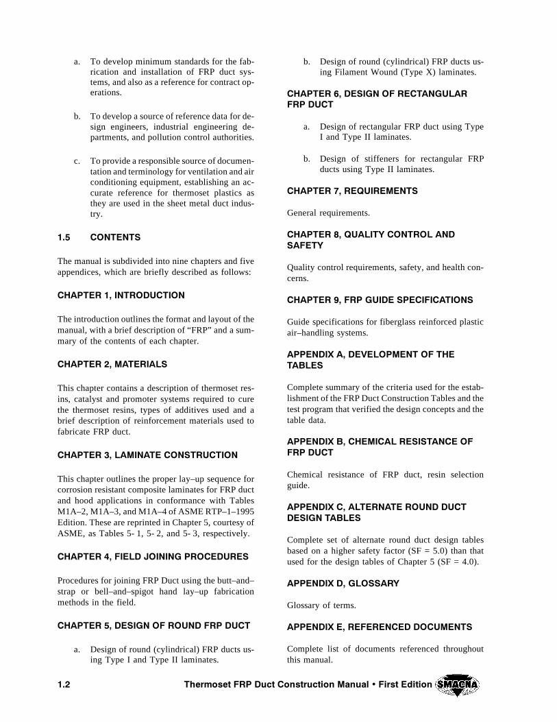
a. To develop minimum standards for the fab-rication and installation of FRP duct sys-tems, and also as a reference for contract op-erations.
b. To develop a source of reference data for de-sign engineers, industrial engineering de-partments, and pollution control authorities.
c. To provide a responsible source of documen-tation and terminology for ventilation and airconditioning equipment, establishing an ac-curate reference for thermoset plastics asthey are used in the sheet metal duct indus-try.
��� #/.4%.43
The manual is subdivided into nine chapters and fiveappendices, which are briefly described as follows:
#(!04%2 �� ).42/$5#4)/.
The introduction outlines the format and layout of themanual, with a brief description of “FRP” and a sum-mary of the contents of each chapter.
#(!04%2 �� -!4%2)!,3
This chapter contains a description of thermoset res-ins, catalyst and promoter systems required to curethe thermoset resins, types of additives used and abrief description of reinforcement materials used tofabricate FRP duct.
#(!04%2 �� ,!-).!4% #/.3425#4)/.
This chapter outlines the proper lay–up sequence forcorrosion resistant composite laminates for FRP ductand hood applications in conformance with TablesM1A–2, M1A–3, and M1A–4 of ASME RTP–1–1995Edition. These are reprinted in Chapter 5, courtesy ofASME, as Tables 5- 1, 5- 2, and 5- 3, respectively.
#(!04%2 �� &)%,$ */).).' 02/#%$52%3
Procedures for joining FRP Duct using the butt–and–strap or bell–and–spigot hand lay–up fabricationmethods in the field.
#(!04%2 �� $%3)'. /& 2/5.$ &20 $5#4
a. Design of round (cylindrical) FRP ducts us-ing Type I and Type II laminates.
b. Design of round (cylindrical) FRP ducts us-ing Filament Wound (Type X) laminates.
#(!04%2 �� $%3)'. /& 2%#4!.'5,!2&20 $5#4
a. Design of rectangular FRP duct using TypeI and Type II laminates.
b. Design of stiffeners for rectangular FRPducts using Type II laminates.
#(!04%2 �� 2%15)2%-%.43
General requirements.
#(!04%2 �� 15!,)49 #/.42/, !.$3!&%49
Quality control requirements, safety, and health con-cerns.
#(!04%2 �� &20 '5)$% 30%#)&)#!4)/.3
Guide specifications for fiberglass reinforced plasticair–handling systems.
!00%.$)8 !� $%6%,/0-%.4 /& 4(%4!",%3
Complete summary of the criteria used for the estab-lishment of the FRP Duct Construction Tables and thetest program that verified the design concepts and thetable data.
!00%.$)8 "� #(%-)#!, 2%3)34!.#% /&&20 $5#4
Chemical resistance of FRP duct, resin selectionguide.
!00%.$)8 #� !,4%2.!4% 2/5.$ $5#4$%3)'. 4!",%3
Complete set of alternate round duct design tablesbased on a higher safety factor (SF = 5.0) than thatused for the design tables of Chapter 5 (SF = 4.0).
!00%.$)8 $� ',/33!29
Glossary of terms.
!00%.$)8 %� 2%&%2%.#%$ $/#5-%.43
Complete list of documents referenced throughoutthis manual.

CHAPTER 2
MATERIALS

#(!04%2 � -!4%2)!,3
4HERMOSET &20 $UCT #ONSTRUCTION -ANUAL � &IRST %DITION ���
��� ).42/$5#4)/.
The use of thermoset FRP ducting to handle corrosivefumes dates back to the 1950’s. These thermoset ma-terials offer similar corrosion resistance and physicalstrength properties when compared to thermoplasticmaterials. Both are identified as “plastics.” However,there is a significant difference during the formingand fabrication stage of each product.
While thermoplastic components are formed usingsolid shapes in a manner similar to metallic fabrica-tion, the thermoset resins are supplied in liquid form,which when combined with fiberglass reinforcement,forms a composite laminate, when applied to a rigidmold surface.
Fabricators of FRP composite laminates require spe-cial skills and training to handle catalysts (initiators)and promoters in order to understand the chemistryof room temperature curing systems.
The catalyzed resin is combined with fiberglass rein-forcement and laid on a solid form, allowed to cure,then removed for installation in the field. Followinglay–up techniques, the FRP components are joined to-gether at the job site using a field wrap of overlappingplies of material. The thickness of the overwrap jointshould at least equal the thickness of the duct lami-nate.
Note: When joining Filament Wound (Type X) lami-nates, a special bond construction is required. (SeeTable 5- 8.)
Thermoset laminates do not melt when heated. Theygenerally retain their physical strength and integrityat elevated temperatures.
��� 4(%2-/3%4 2%3).3
There are various types of thermoset resins used forfabricating FRP duct for corrosion resistant applica-tions. Each of the generic types of resins used todayoffer different properties to be considered when se-lecting a suitable resin for a specific application, e.g.,concentration of chemical environs to be handled andrange of temperatures to which the FRP duct will beexposed. Any questionable applications should be re-solved with the resin supplier. The following resinsare commonly used to fabricate FRP duct for the cor-rosion industry.
����� /RTHOPHTHALIC 2ESINS
Orthophthalic resins are generally referred to as gen-eral purpose ortho resins. These ortho resins exhibitlimited corrosion resistance with poor temperatureproperties (maximum 130̂F (54̂ C)) due to their lowheat distortion temperature of the cured resin system.
Brominated versions of ortho resins are available.Such systems are used for “mine ventilation FRPduct,” where ambient conditions are primarily non–corrosive.
����� )SOPHTHALIC 2ESINS
Isophthalic (iso) resins are available in either rigid orresilient versions. They are classified as unsaturatedpolyesters based on isophthalic acid and glycols ofvarious types, specifically formulated to exhibit thecorrosion resistance properties desired. Brominatedversions of these isophthalic resins are available forflame retardant applications. However, these haloge-nated flame retardant resins require the addition of asynergist, such as antimony trioxide to achieve ClassI ratings as determined by ASTM E84 test methods.(See section 2.6.)
Rigid high molecular weight isophthalic resins areused for moderate corrosion resistant applications upto a maximum temperature of 180^F (82̂ C). Theyare generally used for water, weak acids, and alkalies.They also exhibit good resistance to many solventsand petroleum products such as gasoline and oil.
Resilient isophthalics offer a lesser degree of chemi-cal resistance and should be limited to a maximumtemperature of 150̂F (66̂ C). However, they are re-silient and less susceptible to stress or impact crack-ing and are suitable for filament winding. Theseisophthalic resins are more economical in resin costwhen compared to the premium grades of corrosionresistant thermoset resins.
����� #HLORENDIC 2ESINS
Chlorendic resins are unsaturated, halogenated poly-ester resins based on het acid (hexachlorocyclopenta-diene) or chlorendic anhydride reacted with a stableglycol–NPG (neopentyl glycol).
The chlorendic resins are inherently flame retardant,but require 5% by weight of antimony trioxide toachieve Class I ratings as determined by ASTM E84test methods. (See section 2.6.)
These resins exhibit excellent high temperature resist-ance up to 250̂F (121̂ C) (higher in some applica-

��� 4HERMOSET &20 $UCT #ONSTRUCTION -ANUAL � &IRST %DITION
tions when approved by the resin supplier). The chlo-rendic resins offer very good chemical resistance tomost oxidizing environments, as well as to most con-centrated acids and to some solvents. They are poorin alkaline service. They are also very rigid with poorimpact resistance properties.
����� 6INYL %STER
Vinyl ester resins are methacrylated epoxies similarto unsaturated polyesters such as ortho, iso, and chlo-rendic resins. Both resin types are cured and handledwith the same room temperature curing agents.
Because of their epoxy backbone, these resins exhibitexcellent resistance to most acids, alkalies, hypochlo-rites, and many solvents. They do not perform wellin the presence of strong oxidizers.
The vinyl esters are resilient (4 to 7% tensile elonga-tion), have excellent impact resistance, and highphysical strength properties. They are preferred forfilament winding machine made ducts. In the field,vinyl ester products are handled and joined with ease.
The temperature resistance of unmodified vinyl estersis in the 200 to 220^F (93 to 104^C) range, but in-creases to 250 to 300^F (121 to 150^C) for the higherdensity, cross–linked, novolac modified vinyl estersdescribed below.
Novolac modified vinyl esters have higher densitycross–linking sites available than the general purposevinyl esters. This higher density cross–linking resultsin a more heat resistant polymer network that can tol-erate temperatures up to 300^F (150̂ C). Althoughthe novolac modified resins are less resilient than theunmodified vinyl esters, they still exhibit excellentmechanical properties.
Curing these modified resins may require differentperoxide catalysts to reduce the peak exotherm andprevent cracking or crazing of the resin rich areas.These resins are more reactive and therefore requiregreater care in the fabrication of FRP laminates.
There are flame retardant versions based on brominetechnology which enhances flame retardance, corro-sion resistance, weatherability, and better laminatecolor stability. However, to achieve Class I ratings asdetermined by ASTM E84 test methods, 3 to 5% (byweight of resin) of antimony trioxide is required. (Seesection 2.6.)
����� "ISPHENOL ! &UMARATES
These are made by reacting bisphenol “A” with pro-pylene oxide to form a glycol, then further reactedwith fumaric acid to produce the resin, classified asa rigid unsaturated polyester resin.
The resins offer excellent corrosion resistance tomany acids and alkalies, but are poor in oxidizing en-virons. They are substantially better than isophthalicresins in severe corrosion applications, but are mostdifficult to field wrap (adhesion problems). Bisphenol“A” resins are available in flame retardant versions,but generally have been replaced with vinyl estercounterparts.
����� /THER 2ESIN -ATERIALS
Furan, phenolic, and acrylic resins are not covered inthis manual. While these resins can be used to fabri-cate air handling equipment and ductwork, they havephysical properties, handling, and application charac-teristics substantially different from the materialscovered by this document.
��� -)8).' !.$ #52).' 4(%2-/3%43
Unsaturated polyester and vinyl ester resins are usual-ly shipped in 55 gallon (208 liter) drums in liquidform. They are available in low viscosity versions,suitable for hand lay–up, spray–up, or filament wind-ing.
Many of the resins are sold as low viscosity, thixedand prepromoted, for ease of handling in the shop orfield fabrication.
All of the above thermosets are cured using room tem-perature catalyst systems which are mixed into theliquid resin prior to lay–up.
��� #!4!,9343� 02/-/4%23� ).()") 4/23� !.$ /4(%2 !$$)4)6%3
For room temperature (RT) cure systems, catalysts,also referred to as initiators, are organic peroxideswhich react with a suitable promoter to initiate thechemical exothermic reaction that polymerizes theresin and cures it into a hardened solid mass.
Methyl ethyl ketone peroxide (MEKP) is the mostwidely used room temperature cure catalyst system.MEKP requires a promoter such as cobalt octoate orcobalt naphthenate to generate free radicals whichstart the resin to polymerize. Sometimes differentamines are added to accelerate the gel and cure time
4HERMOSET &20 $UCT #ONSTRUCTION -ANUAL � &IRST %DITION ���
of the resin. CAUTION: THE MEKP MUST NEVERBE ADDED DIRECTLY TO THE COBALT NAPH-THENATE OR OCTOATE PROMOTER. When di-rectly added to each other, they may be EXPLOSIVE-LY REACTIVE. Care must be taken to observe theseprecautions to prevent accidents.
When the resins are not received prepromoted, therecommended quantity of the promoter (see resinmanufacturer’s data sheet for the amounts required)can be added to the liquid resin and thoroughly mixedinto the drum or master batch of resin being preparedfor use.
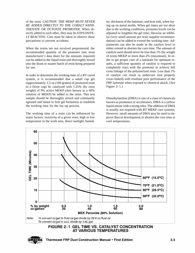
In order to determine the working time of a RT curedsystem, it is recommended that a small cup gel(approximately 3.5 oz (100 grams) of promoted resinin a Dixie cup) be catalyzed with 1.25% (by resinweight) of 9% active MEKP (also known as a 60%solution of MEKP) be added to the resin. This testsample should be thoroughly mixed and continuallyagitated and timed to first gel formation to establishthe working time for the lay–up process.
The working time of a resin can be influenced bymany factors: reactivity of a given resin, high or lowtemperature in the work area, direct sunlight, humid-
ity, thickness of the laminate, and heat sink, when lay-ing up on metal molds. When gel times are too shortdue to the working conditions, promoter levels can beadjusted to lengthen the gel time; likewise an inhibi-tor (very small amount per resin supplier recommen-dation) can be added to extend the working time. Ad-justments can also be made in the catalyst level toeither extend or shorten the cure time. The amount ofcatalyst used should never be less than 1% (by weightof resin) MEKP or more than 2% (maximum). In or-der to get proper cure of a laminate for optimum re-sults, a sufficient quantity of catalyst is required tocompletely react with the promoter to achieve fullcross linkage of the polymerized resin. Less than 1%of catalyst can result in undercure (not properlycross–linked) with resultant poor performance of theFRP laminate when exposed to chemical attack. (SeeFigure 2- 1.)
Dimethylaniline (DMA) is one of a class of chemicalsknown as promoters or accelerators. DMA is a yellowliquid amine with a strong odor. The addition of DMAis usually not required with RT MEKP cure systems.However, small amounts of DMA may be used to im-prove Barcol development or shorten the cure time atcool temperatures.
&)'52% � � '%, 4)-% 63� #!4!,934 #/.#%.42!4)/.!4 6!2)/53 4%-0%2!452%3
�
��
��
��
��
��
��
-%+ 0EROXIDE ���� 3OLUTION
'%,4)-
%�-
INUTES
��� ��� ��� ���CC�GALLON �� �� �� ��� BY WEIGHT
��O& �����O#
��O& �����O#
��O& �����O#
.OTE� 4O CONVERT CC�GAL TO FLUID OZ�GAL DIVIDE BY ���� CC�FLUID OZ
4O CONVERT CC�GAL TO CC�, DIVIDE BY ���,�GAL
��O& �����O#
��� 4HERMOSET &20 $UCT #ONSTRUCTION -ANUAL � &IRST %DITION
CAUTION – Promoters should always be mixed thor-oughly into the resin before adding the catalyst.
Inhibitors are used to lengthen the gel time of unsatu-rated polyesters and vinyl ester resins. Inhibitors areuseful when very long gel times are required, or whenresins are curing too quickly due to high temperature.
It is recommended that the resin manufacturer beasked which particular inhibitor system is suitable foruse in their resin.
Thixotropes, commonly called fumed silicas, are usedto thicken low viscosity resins to reduce resin drain-age on vertical surfaces during lay up. Unsaturatedpolyesters are readily available with the fumed silicamixed into the resins. Fumed silica can be added tovinyl ester resins using a high shear mixer to ensureuniform dispersion at the job site. Resins thus treatedmay exhibit a shortened shelf life.
Vinyl ester resins are less stable than most unsaturat-ed polyesters when thixed and promoted, or whenstored at above 70 to 75^F (21 to 24^C). Keep out ofdirect sunlight.
Cured non–halogenated polyester or vinyl ester resinlaminates will burn readily when exposed to flame,heat, and oxygen. However, when these resins are for-mulated with a stable cross linked halogen such aschlorine or bromine as cooked into the formulation,these halogenated resins exhibit flame retardant prop-erties which are further enhanced with the addition ofan antimony oxide such as antimony trioxide or anti-mony pentoxide. The antimony acts as a synergistwhich reacts with the halogen source to greatly im-prove the resin’s flame retardant properties. The anti-mony by itself, when added to a non–flame retardantresin, does not impart any flame retardance, but actsonly as a costly filler with possible lower chemicalresistant properties. The use of antimony oxidescauses the normally clear translucent laminate to turnopaque which creates problems for inspectors to visu-ally examine the laminate for fabrication flaws. Whenit is critical for the corrosion liner to be visually clearfor optimum corrosion resistance, it is recommendedthat antimony be added to the outer structural portionof the laminate only, such fabrication is commonlyaccepted by the chemical industry requiring Class Iflame retardance.
��� -!4%2)!,3 (!.$,).'
When handling catalysts, cobalt promoters, DMA,and inhibitors, proper care must be taken to handle
each product in a safe manner as shown on the Materi-al Safety Data Sheet as supplied by each productmanufacturer. These safety data sheets should bethoroughly read and understood prior to working withthese chemical products.
��� &,!-% 2%4!2$!.#% !.$ 3-/+%'%.%2!4)/.
The flame retardancy and smoke generation of ther-moset FRP laminates are determined by the ASTME84 tunnel test method, under supervised conditionsat accredited test agencies equipped to perform suchtests. This rating system is based on a scale that hasassigned asbestos cement board a flame spread (FS)value of zero and red oak a flame spread (FS) of 100.
R Class I laminates exhibit less than 25 FS.
R Class II laminates exhibit less than 75 FS.
R Class III laminates have greater than 75 FS.
Note: Within a given class of laminates, smoke gener-ation varies depending on the types of resin and halo-gen used. Formulation selection and the applicationof intumescent coatings have been used to reducesmoke generation levels.
Flame spread and smoke development ratings aregenerally based on test results obtained from con-trolled or small–scale bench tests. They are not neces-sarily predictive of product performance in a real firesituation. Polyester and vinyl ester resins are organicmaterials and the resins and products made from themwill burn under the right conditions of heat and oxy-gen supply. The numerical flame spread rating is notintended to reflect hazards presented by this, or anyother material, under actual fire conditions.
For hand lay–up laminates, using halogenated resins,3 to 5% of antimony trioxide or pentoxide are re-quired to achieve Class I FS ratings. The percent addi-tive ratio of both trioxide and pentoxide are not al-ways equal on a 1:1 basis. The resin manufacturer willcategorize the correct FS values obtained with eitherof the antimony oxide systems as evaluated with eachspecific resin as tested.
Antimony pentoxide is supplied in a liquid colloidalsuspension, while antimony trioxide is supplied inpowder form. The liquid pentoxide usually lengthensthe gel time and can retard surface cure when toomuch of the additive is used. However, the pentoxidesolutions do not completely turn the laminate opaque,but rather allow some translucency of the cured lami-nate, which is beneficial for inspection purposes.
4HERMOSET &20 $UCT #ONSTRUCTION -ANUAL � &IRST %DITION ���
��� 5,42!6)/,%4 34!"),):%23
FRP duct exposed to outdoor weathering may suffersurface degradation, chalking, and discolorationwhen exposed to the sun, rain and wind. Polyestersare more ultraviolet (UV) stable than vinyl ester re-sins. The addition of a suitable UV stabilizer to theoutermost layer will retard the rate of degradation.
��� 490%3 /& 2%).&/2#%-%.4
The selection of glass reinforcement depends on thecapabilities of a specific thermosetting resin in com-bination with the various types of available glassmanufacturers’ products. The glass should wet outreadily and no glass fiber should be visible in the finalcured laminate. The basic forms of reinforcementused are:
R surfacing veil
R chopped strand mat
R woven roving
R continuous strand roving (filament winding)
����� 3URFACING 6EIL
The surfacing veil provides reinforcement for the res-in rich liner, which prevents the cracking or crazingof this resin surface and also acts to block protrudingthicker glass fibers (chopped strand mat) from reach-ing the surface and providing chemical wicking intothe laminate structure. The most common type of sur-facing veil used is “C” glass veil. However, when thecorrodent attacks glass, a synthetic fiber (saturatedpolyester), such as NEXUSQ, can be used in placeof “C” veil.
Carbon veil or mat and synthetic conductive veil aresometimes specified to provide a conductive surface
for static electric charge dissipation to ground. Car-bon veil is also good for corrosion control and abra-sion resistance.
����� #HOPPED 3TRAND -AT
Two types of chopped strand mat are used for corro-sion control Type “E” (electrical grade) and “ECR”glass (electrical corrosion resistant). The glass fibersare chemically treated and coated to enhance wet outby the resin. The fibers are bundled to form continu-ous multi–fiber strands held together with a compat-ible binder. The glass fibers are chopped in place toform a flat mat surface of various weights and thick-ness: 0.75, 1.5, and 2.0 oz/ft2 (225, 450, and 610g/m2) are most often used for corrosion applications.
Spray–chop uses continuous fiber chopped and wetout with resin onto the mold. This method is common-ly used on larger surfaces to save labor.
Both mat and spray–chop require hand roll–out todensify the resulting laminate.
����� 7OVEN 2OVING
Woven roving consists of continuous glass fiber rov-ings that are woven together to form a heavy wovenmaterial which is available in several weights andthicknesses. Alternating layers of woven roving andchopped strand mat are used to form the structurallayer of the laminate. Woven roving greatly increasesthe physical properties of a composite laminate.
����� #ONTINUOUS 3TRAND 2OVING
The continuous glass fibers are wound into a cylindri-cal package for processing. Continuous strand rovingis used for filament winding or chopped in place forspray up applications to replace chopped strand mat.Filament winding provides higher strengths at lowerthicknesses. However, the filament wound laminateby itself has limited corrosion resistance.

��� 4HERMOSET &20 $UCT #ONSTRUCTION -ANUAL � &IRST %DITION
4()3 0!'% ).4%.4)/.!,,9 ,%&4 ",!.+

CHAPTER 3
LAMINATE CONSTRUCTION

#(!04%2 � ,!-).!4% #/.3425#4)/.
���4HERMOSET &20 $UCT #ONSTRUCTION -ANUAL � &IRST %DITION
��� ).42/$5#4)/.
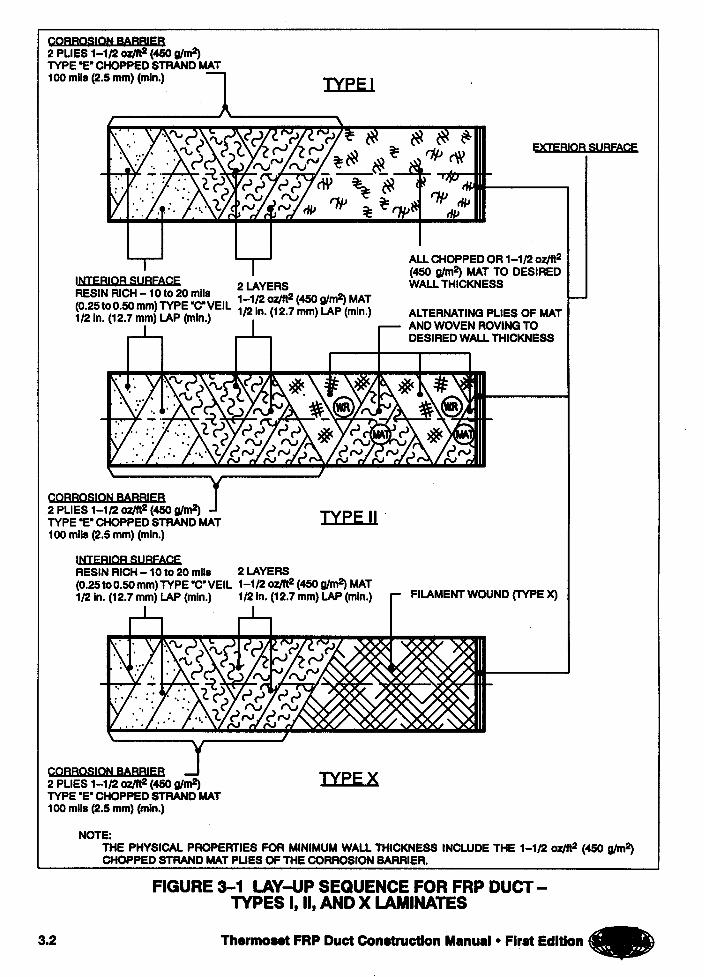
The laminate construction sequence for corrosion re-sistant FRP laminates is based on industry standardsASTM C581, ASTM C582, and ASME RTP–1–1995.The information provided in this manual for FRP ductand hoods supplements ASTM D3982–92 StandardSpecification for Contact Molded “Fiberglass” (GlassFiber Reinforced Thermosetting Resin) Duct andHoods. (See Figure 3- 1.)
��� #/22/3)/. "!22)%2 2%3).
The resin used shall be a commercial–grade polyesteror vinyl ester, acceptable for the service conditionsas tested by ASTM C581 or from established case his-tories, documenting the suitability of the resin for theservice conditions.
The resin may contain, flame retardant additives inaccordance with the resin producers’ recommenda-tions or as allowed in ASTM C582. The resin may notcontain any fillers or pigments unless agreed to by theend user.
If static electricity is a factor for consideration, theinner surface of the ductwork shall be grounded witha maximum resistance to ground of 105 W. This con-ductive surface can be fabricated with carbon veil orsynthetic conductive veil plus resin to form a conduc-tive liner for static electricity control. (Consult yourresin supplier for formulation and test methods re-quired.)
��� #/22/3)/. "!22)%2
This critical segment of the laminate consists of a res-in rich inner surface, followed by an interior layerlayed–up using two plies of 1–1/2 oz/ft2 (450 g/m2)chopped mat, for a combined minimum thickness of100 mils (2.5 mm) in all laminates (Types I, II, andX).
����� )NNER 3URFACE
The inner corrosion resistant surface is a resin richlayer reinforced with surfacing veil (Type “C” glassveil or NEXUSQ synthetic fiber). This layer isapproximately 90% resin and 10% reinforcement, re-sulting in a layer 10 to 20 mils (0.25 to 0.50 mm)thick.
����� )NTERIOR ,AYER �#ORROSION "ARRIER
This layer is formed with 2 plies of 1–1/2 oz/ft2 (450g/m2) chopped strand mat or equivalent choppedstrand roving, treated with a compatible sizing sys-tem, containing approximately 75% resin and 25% fi-ber reinforcement. The fiber length shall be 1/2 in.(12.7 mm) minimum to 2 in (50.8 mm) maximum,randomly dispersed. For FRP duct the physicalstrength properties of the interior layers have been in-cluded in calculating the minimum strength proper-ties required for the FRP duct system.
��� 3425#452!, ,!9%2
The structural portion of the laminate (including matlayers of the corrosion barrier), which is designed toprovide the physical strength properties required forthe FRP duct, shall be laid up as follows:
a. Type I – Apply all chopped strand mat orequivalent chopped strand roving in thespray–up method, to achieve the designedminimum thickness (70 to 75% resin, 25 to30% glass). (See Table 5- 1.)
b. Type II – Apply alternating plies of choppedstrand mat or equivalent chopped strand rov-ing, interspersed with a ply of woven–roving24 oz/yd2 (810 g/m2) as required by theconstruction sequence to achieve the mini-mum required design thickness. Woven rov-ing must be separated with a ply of choppedmat or chopped fiber, (55 to 72% resin, 28to 45% glass). (See Table 5- 2.)
c. Type X – Apply filament wound continuousstrand roving to achieve the designed mini-mum wall thickness (40 to 50% resin, 50 to60% glass). (See Table 5- 6.)
��� %84%2)/2 352&!#%
For added service life, the exterior surface over wo-ven roving or filament winding may have a layer ofchopped fiber or surfacing veil to provide corrosionresistance to chemical spillage and weathering.
The exterior surface shall be coated with a resin richlayer containing paraffin wax to prevent air inhibitionof surface resin cure. The exterior surface glass rein-forcement plus resin should also contain a UV (ultra-violet) screener, a pigment, or be painted to resist UVdegradation of the cured surface resin, particularlywhen FRP ducting is exposed outdoors.
Pigmentation can be incorporated into the exteriorsurface for appearance and color coding of the ductinstallation.
���4HERMOSET &20 $UCT #ONSTRUCTION -ANUAL � &IRST %DITION
To enhance flame and smoke properties, an intumes-cent coating can be used on the exterior surface(check with your resin supplier).
��� 0/4%.4)!, !$(%3)/. 02/",%-3$52).' ,!-).!4% #/.3425#4)/.
It is important to recognize that thermoset compositelaminates, when fully cured, do not chemically bondtogether. The cured surfaces must be properly pre-pared for secondary bonding.
During laminate construction, it is not advisable to layup the corrosion barrier and leave it to fully cure overseveral days (weekend – holiday). If this is unavoid-able, the entire outer surface must be roughened to re-move hardened resin. Then, prior to overlaying withthe structural portion of the laminate, the roughenedsurface should be coated with catalyzed resin andchopped glass fiber to form a tie coat for the subse-quent plies of the structural layer, thus creating an ac-ceptable interlaminar mechanical bond.
Under normal conditions, the sections of duct andhoods should be completed within a 24 hour periodto achieve a chemical bond.
��� 7!,, 4()#+.%33 4/,%2!.#%
The design wall thickness (also referred to as requiredwall thickness) shall be as selected for the applicationfrom the appropriate tables for round (ChapterNO TAG) or rectangular (Chapter 6) duct, but in nocase less than 1/8 in. (3.18 mm) thick. For the purposeof evaluating the acceptability of a duct’s wall thick-ness, its average wall thickness shall be establishedas the arithmetic average of six spot thickness valuestaken at random. This average thickness shall not beless than 85%, nor greater than 120%, of the designwall thickness. Additionally, of all thickness readings
taken, the lowest shall not be less than 70%, nor great-er than 130%, of the design wall thickness. (See Chap-ter 8 – Quality Control and Safety for additional re-quirements and testing.)
��� -%#(!.)#!, 02/0%24)%3
The minimum physical properties for Types I and II,and Filament Wound (Type X) laminates shall be asshown in Tables 5- 3 and 5- 7, respectively. Lami-nates which do not meet the minimum values may beconsidered acceptable provided that they are designedand fabricated to afford the same overall strengthbased on a necessarily thicker laminate.
��� 352&!#% (!2$.%33
The laminate shall have an average Barcol hardnessof at least 90% of the resin manufacturer’s publishedhardness for the cured resin, when tested in accor-dance with ASTM D2583. (See section 8.1.4 – for de-tailed surface hardness requirements and testing.)
Exception: Laminate surfaces finished with syntheticveil and resin are considered adequately cured whenthe average hardness, established as describedabove, equals or exceeds 80% of the Barcol hardnessvalue established by the resin manufacturer for thecured resin.
���� !00%!2!.#%
The corrosion barrier laminate shall be free of visualdefects, such as foreign inclusions, dry spots, airbubbles, pinholes, pimples and delamination as de-fined by ASTM–2563 Level II. The remainder of thelaminate (outer structural portion) shall be free ofvisual defects as commercially practical. The exteriorsurface shall be smooth and resin rich with no dry fi-ber visible. All cut ends shall be resin coated to pre-vent moisture absorption.

��� 4HERMOSET &20 $UCT #ONSTRUCTION -ANUAL � &IRST %DITION
4()3 0!'% ).4%.4)/.!,,9 ,%&4 ",!.+
CHAPTER 4
FIELD JOINING PROCEDURES
#(!04%2 � &)%,$ */).).' 02/#%$52%3
���4HERMOSET &20 $UCT #ONSTRUCTION -ANUAL � &IRST %DITION
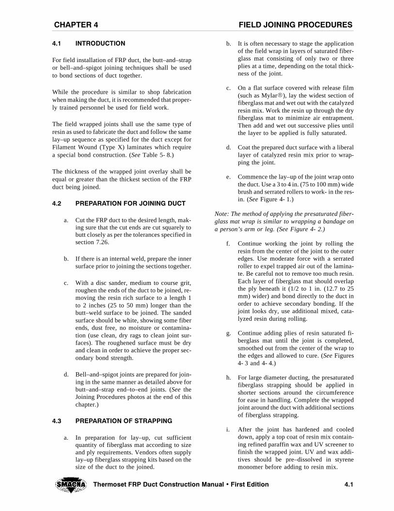
��� ).42/$5#4)/.
For field installation of FRP duct, the butt–and–strapor bell–and–spigot joining techniques shall be usedto bond sections of duct together.
While the procedure is similar to shop fabricationwhen making the duct, it is recommended that proper-ly trained personnel be used for field work.
The field wrapped joints shall use the same type ofresin as used to fabricate the duct and follow the samelay–up sequence as specified for the duct except forFilament Wound (Type X) laminates which requirea special bond construction. (See Table 5- 8.)
The thickness of the wrapped joint overlay shall beequal or greater than the thickest section of the FRPduct being joined.
��� 02%0!2!4)/. &/2 */).).' $5#4
a. Cut the FRP duct to the desired length, mak-ing sure that the cut ends are cut squarely tobutt closely as per the tolerances specified insection 7.26.
b. If there is an internal weld, prepare the innersurface prior to joining the sections together.
c. With a disc sander, medium to course grit,roughen the ends of the duct to be joined, re-moving the resin rich surface to a length 1to 2 inches (25 to 50 mm) longer than thebutt–weld surface to be joined. The sandedsurface should be white, showing some fiberends, dust free, no moisture or contamina-tion (use clean, dry rags to clean joint sur-faces). The roughened surface must be dryand clean in order to achieve the proper sec-ondary bond strength.
d. Bell–and–spigot joints are prepared for join-ing in the same manner as detailed above forbutt–and–strap end–to–end joints. (See theJoining Procedures photos at the end of thischapter.)
��� 02%0!2!4)/. /& 342!00).'
a. In preparation for lay–up, cut sufficientquantity of fiberglass mat according to sizeand ply requirements. Vendors often supplylay–up fiberglass strapping kits based on thesize of the duct to the joined.
b. It is often necessary to stage the applicationof the field wrap in layers of saturated fiber-glass mat consisting of only two or threeplies at a time, depending on the total thick-ness of the joint.
c. On a flat surface covered with release film(such as MylarQ), lay the widest section offiberglass mat and wet out with the catalyzedresin mix. Work the resin up through the dryfiberglass mat to minimize air entrapment.Then add and wet out successive plies untilthe layer to be applied is fully saturated.
d. Coat the prepared duct surface with a liberallayer of catalyzed resin mix prior to wrap-ping the joint.
e. Commence the lay–up of the joint wrap ontothe duct. Use a 3 to 4 in. (75 to 100 mm) widebrush and serrated rollers to work- in the res-in. (See Figure 4- 1.)
Note: The method of applying the presaturated fiber-glass mat wrap is similar to wrapping a bandage ona person’s arm or leg. (See Figure 4- 2.)
f. Continue working the joint by rolling theresin from the center of the joint to the outeredges. Use moderate force with a serratedroller to expel trapped air out of the lamina-te. Be careful not to remove too much resin.Each layer of fiberglass mat should overlapthe ply beneath it (1/2 to 1 in. (12.7 to 25mm) wider) and bond directly to the duct inorder to achieve secondary bonding. If thejoint looks dry, use additional mixed, cata-lyzed resin during rolling.
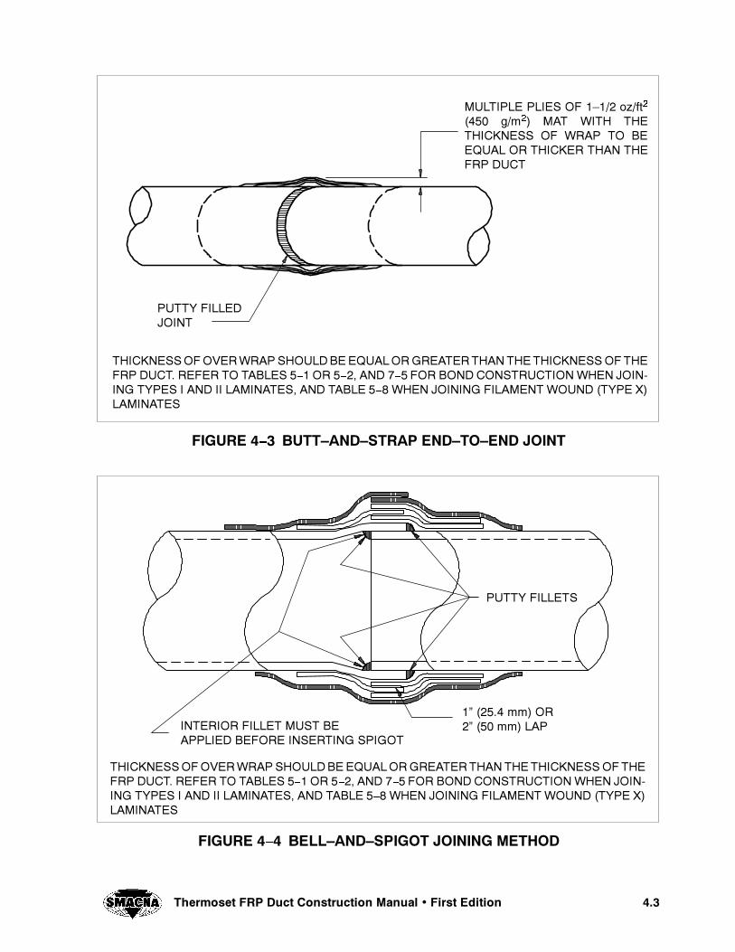
g. Continue adding plies of resin saturated fi-berglass mat until the joint is completed,smoothed out from the center of the wrap tothe edges and allowed to cure. (SeeFigures4- 3 and 4- 4.)
h. For large diameter ducting, the presaturatedfiberglass strapping should be applied inshorter sections around the circumferencefor ease in handling. Complete the wrappedjoint around the duct with additional sectionsof fiberglass strapping.
i. After the joint has hardened and cooleddown, apply a top coat of resin mix contain-ing refined paraffin wax and UV screener tofinish the wrapped joint. UV and wax addi-tives should be pre–dissolved in styrenemonomer before adding to resin mix.

��� 4HERMOSET &20 $UCT #ONSTRUCTION -ANUAL � &IRST %DITION
%15!, /6%2,!0/. %!#( 3)$%
&)'52% � � 02%0!2!4)/. /& 342!00).'
��� OZ�FT����� G�M
� #(/00%$ 342!.$ -!4
�ì TO �ì ��� TO ���MM7)$4( &)234 0,9
,!9 50 /.2%,%!3% &),-
�ì ����� MM /6%2,!03)$%3 !.$ %.$3
&)"%2',!33-!4 )-02%'.!4%$7)4( 2%3). 4/ &/2-!. ).4%'2!,5.)4 &/2"544 !.$342!0 &)%,$ */).43� 2%&%2 4/ 4!",%3 � � /2 � �� !.$ � � &/2 "/.$ #/.3425#4)/.7(%. */).).' 490%3 ) !.$ )) ,!-).!4%3� !.$4!",% � �7(%. */).).' &),!-%.47/5.$�490% 8 ,!-).!4%3
&)'52% � � !00,)#!4)/. /& 342!00).'
2/5'(%.%$!2%!
",%.$ !2%!3
05449 &),,%$
4()#+.%33/&/6%272!0 3(/5,$"% %15!,/2'2%!4%24(!. 4(%4()#+.%33/& 4(%&20 $5#4� 2%&%2 4/ 4!",%3 � � /2 � �� !.$ � � &/2 "/.$ #/.3425#4)/. 7(%. */). ).' 490%3 ) !.$ )) ,!-).!4%3� !.$ 4!",% � � 7(%. */).).' &),!-%.4 7/5.$ �490% 8,!-).!4%3
���4HERMOSET &20 $UCT #ONSTRUCTION -ANUAL � &IRST %DITION
&)'52% � � "544â!.$â342!0 %.$â4/â%.$ */).4
4()#+.%33/&/6%272!0 3(/5,$"% %15!,/2'2%!4%24(!. 4(%4()#+.%33/& 4(%&20 $5#4� 2%&%2 4/ 4!",%3 � � /2 � �� !.$ � � &/2 "/.$ #/.3425#4)/. 7(%. */). ).' 490%3 ) !.$ )) ,!-).!4%3� !.$ 4!",% � � 7(%. */).).' &),!-%.4 7/5.$ �490% 8,!-).!4%3
05449 &),,%$*/).4
-5,4)0,% 0,)%3 /& ��� OZ�FT�
���� G�M� -!4 7)4( 4(%4()#+.%33 /& 72!0 4/ "%%15!, /2 4()#+%2 4(!. 4(%&20 $5#4
&)'52% � � "%,,â!.$â30)'/4 */).).' -%4(/$
05449 &),,%43
4()#+.%33/&/6%272!0 3(/5,$"% %15!,/2'2%!4%24(!. 4(%4()#+.%33/& 4(%&20 $5#4� 2%&%2 4/ 4!",%3 � � /2 � �� !.$ � � &/2 "/.$ #/.3425#4)/. 7(%. */). ).' 490%3 ) !.$ )) ,!-).!4%3� !.$ 4!",% � � 7(%. */).).' &),!-%.4 7/5.$ �490% 8,!-).!4%3
).4%2)/2 &),,%4 -534 "%!00,)%$ "%&/2% ).3%24).' 30)'/4
�ì ����� MM /2�ì ��� MM ,!0
��� 4HERMOSET &20 $UCT #ONSTRUCTION -ANUAL � &IRST %DITION
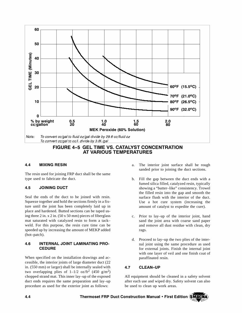
&)'52% � � '%, 4)-% 63� #!4!,934 #/.#%.42!4)/.!4 6!2)/53 4%-0%2!452%3
�
��
��
��
��
��
��
-%+ 0EROXIDE ���� 3OLUTION
'%,4)-
%�-
INUTES
��� ��� ��� ���CC�GALLON �� �� �� ��� BY WEIGHT
��O& �����O#
��O& �����O#��O& �����O#
��O& �����O#
.OTE� 4O CONVERT CC�GAL TO FLUID OZ�GAL DIVIDE BY ���� CC�FLUID OZ
4O CONVERT CC�GAL TO CC�, DIVIDE BY ���,�GAL
��� -)8).' 2%3).
The resin used for joining FRP duct shall be the sametype used to fabricate the duct.
��� */).).' $5#4
Seal the ends of the duct to be joined with resin.Squeeze together and hold the sections firmly in a fix-ture until the joint has been completely laid up inplace and hardened. Butted sections can be taped us-ing three 2 in. x 2 in. (50 x 50 mm) pieces of fiberglassmat saturated with catalyzed resin to form a tack–weld. For this purpose, the resin cure time can bespeeded up by increasing the amount of MEKP added(hot–patch).
��� ).4%2.!, */).4 ,!-).!4).' 02/ #%$52%
When specified on the installation drawings and ac-cessible, the interior joints of large diameter duct (22in. (550 mm) or larger) shall be internally sealed withtwo overlapping plies of 1–1/2 oz/ft2 (450 g/m2)chopped strand mat. This inner lay–up of the exposedduct ends requires the same preparation and lay–upprocedure as used for the exterior joint as follows:
a. The interior joint surface shall be roughsanded prior to joining the duct sections.
b. Fill the gap between the duct ends with afumed silica filled, catalyzed resin, typicallyshowing a “butter–like” consistency. Trowelthe filled resin into the gap and smooth thesurface flush with the interior of the duct.Use a hot cure system (increasing theamount of catalyst to expedite the cure).
c. Prior to lay–up of the interior joint, handsand the joint area with coarse sand paperand remove all dust residue with clean, dryrags.
d. Proceed to lay–up the two plies of the inter-nal joint using the same procedure as usedfor external joints. Finish the internal jointwith one layer of veil and one finish coat ofparaffinated resin.
��� #,%!.â50
All equipment should be cleaned in a safety solventafter each use and wiped dry. Safety solvent can alsobe used to clean up work areas.

���4HERMOSET &20 $UCT #ONSTRUCTION -ANUAL � &IRST %DITION
*/).).' 02/#%$52%3
#OURTESY OF !SHLAND #HEMICAL
1 Firmly support pipe sections. Square the ends tobe joined using a saber saw.
3 Coat roughened end edges of pipe with smallamount of catalyzed resin. Any large voids may befilled with a fumed silica filled resin putty.
2 Rough the outside surfaces with sander approxi-mately 1 in. (25 mm) farther in from the ends thanthe finished joint surface. Where inside joints are pos-sible, interior surfaces should be sanded prior to as-sembly.
4 Support components in joint position as rigidly aspossible so that no movement occurs while makingthe joint. Fill joint with resin.
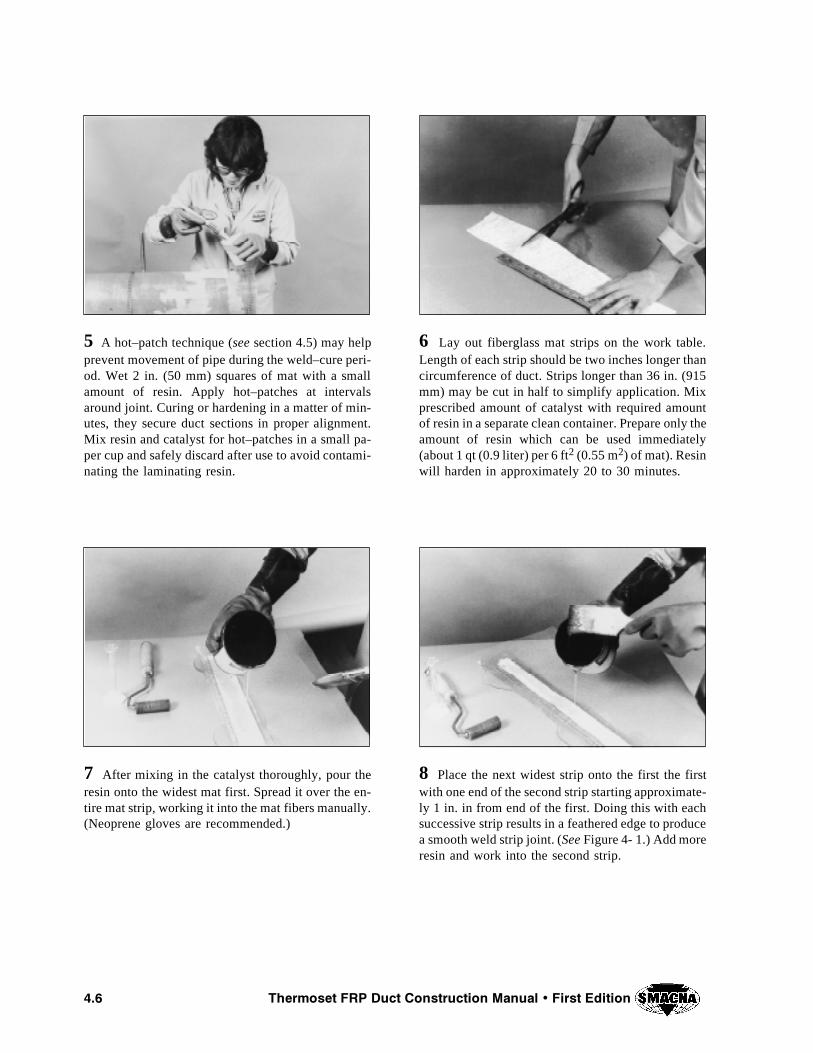
��� 4HERMOSET &20 $UCT #ONSTRUCTION -ANUAL � &IRST %DITION
5 A hot–patch technique (see section 4.5) may helpprevent movement of pipe during the weld–cure peri-od. Wet 2 in. (50 mm) squares of mat with a smallamount of resin. Apply hot–patches at intervalsaround joint. Curing or hardening in a matter of min-utes, they secure duct sections in proper alignment.Mix resin and catalyst for hot–patches in a small pa-per cup and safely discard after use to avoid contami-nating the laminating resin.
7 After mixing in the catalyst thoroughly, pour theresin onto the widest mat first. Spread it over the en-tire mat strip, working it into the mat fibers manually.(Neoprene gloves are recommended.)
6 Lay out fiberglass mat strips on the work table.Length of each strip should be two inches longer thancircumference of duct. Strips longer than 36 in. (915mm) may be cut in half to simplify application. Mixprescribed amount of catalyst with required amountof resin in a separate clean container. Prepare only theamount of resin which can be used immediately(about 1 qt (0.9 liter) per 6 ft2 (0.55 m2) of mat). Resinwill harden in approximately 20 to 30 minutes.
8 Place the next widest strip onto the first the firstwith one end of the second strip starting approximate-ly 1 in. in from end of the first. Doing this with eachsuccessive strip results in a feathered edge to producea smooth weld strip joint. (See Figure 4- 1.) Add moreresin and work into the second strip.

���4HERMOSET &20 $UCT #ONSTRUCTION -ANUAL � &IRST %DITION
9 Add other strips in the same manner. In preparingeach strip, it is best to be a little “lean” on resin atthis stage rather than over–wetting. More resin maybe added later, if necessary. After laying the finalstrip, compress strips together with glove–protectedhand to remove large air bubbles and to make sure alllayers are wetted with the resin.
11 Be sure the joining strip is centered, with caretaken to avoid wrinkles on the under or back side ofthe joint. Continue applying the strip around the jointuntil the free end overlaps the beginning. Lightlypress out the air bubbles with gloved hands.
10 Pick up the completed joining strip by one endand center it carefully on the duct joint. Apply the ta-pered end first with the narrowest strip placed directlyon the duct joint.
12 Finish the application of the joining strip withthe roller. Any remaining air bubbles will appear aslight spots. These should be rolled to the edge of thejoint where they will be released and disappear. Ifjoint is not a straight butt joint, a little extra rollingand hand work to shape mat strips to structure config-uration will eliminate bumps and ridges.
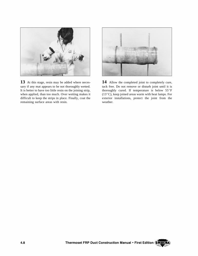
��� 4HERMOSET &20 $UCT #ONSTRUCTION -ANUAL � &IRST %DITION
13 At this stage, resin may be added where neces-sary if any mat appears to be not thoroughly wetted.It is better to have too little resin on the joining strip,when applied, than too much. Over wetting makes itdifficult to keep the strips in place. Finally, coat theremaining surface areas with resin.
14 Allow the completed joint to completely cure,tack free. Do not remove or disturb joint until it isthoroughly cured. If temperature is below 55^F(13^C), keep joined areas warm with heat lamps. Forexterior installations, protect the joint from theweather.
CHAPTER 5
DESIGN OF ROUND FRP DUCT
#(!04%2 � $%3)'. /& 2/5.$ &20 $5#4
���4HERMOSET &20 $UCT #ONSTRUCTION -ANUAL � &IRST %DITION
��� $%3)'. /& 2/5.$ &20 $5#43 53 ).' 490%3 ) !.$ )) ,!-).!4%3
����� )NTRODUCTION
The design procedures and fabrication requirementsdescribed in this chapter apply to round (cylindrical)FRP ducts, intended for positive and negative pres-sure (vacuum) systems, operating in corrosive envi-ronments at temperatures up to 180^F (82^C) andfabricated from laminates based on thermoset polyes-ter resins having a heat deflection temperature (HDT)of 180^F (82^C) or higher. Higher temperature ap-plications require special premium grade resins ex-hibiting higher HDT’s to suit the higher temperaturerequirements based on the resin manufacturer’s rec-ommendations for such service.
Exception: Laminates fabricated from resin systemshaving an HDT of less than 180^F (82^C) may beused to fabricate FRP ducts designed using the proce-dures and tables contained in this manual when thecorrosion and operation temperature requirements ofthe intended application can be met with the selectedresin system.
FRP ducts fabricated per the requirements of this sec-tion shall be fabricated by hand lay–up or contactmolding methods using Types I and II laminates asdescribed in Chapter 3.
����� -INIMUM ,AMINATE 0HYSICAL #HARAC TERISTICS
The number and sequence of plies of fiberglass rein-forcement required for each type and laminate thick-ness are listed in Tables 5- 1 and 5- 2. The minimumrequired physical characteristics for laminate TypesI and II are listed in Table 5- 3. These tables are re-printed from ASME RTP–1–1995 Edition, courtesyof the American Society of Mechanical Engineers.
The physical characteristics of the design laminate,on which the duct fabrication is predicated, must meetor exceed the minimum values listed in Table 5- 3.Substantiation of laminate properties may be in theform of current or historical test records for the lami-nate under consideration. Tests supporting laminateproperties must have been performed per the require-ments of ASTM D638–96.
Note: Duct construction using Filament Wound (TypeX) laminates is discussed in section 5.2, including de-sign tables and minimum laminate physical charac-teristics.
����� $ESIGN FOR .EGATIVE 0RESSURE�6ACUUM
For the practical application of the tables in this sec-tion, it suffices to say that Tables 5- 4 and 5- 4M listthe maximum recommended operating negative pres-sure for Types I and II laminates.
Note: For a detailed discussion of the developmentof the design tables contained in this manual, the as-sumptions and design concepts on which the ratingsare based, and the testing program which validatesthe results, see Appendix A.
The data in Tables 5- 4 and 5- 4M is arranged withthe nominal laminate thickness heading the columnsand a series of duct diameters listed vertically, start-ing with the smallest at 4 in. (100 mm) to the largestat 72 in. (1800 mm).
The tables are based on two important assumptions:
a. the safety factor for each combination oflaminate thickness and diameter is equal toor greater than 4.0, and
b. the distance between supports is a maximumof 10 ft (3050 mm).
Typically, before selecting the required laminatethickness for a particular application, the system de-sign pressure (positive or negative), the duct diame-ter, and the laminate type are known.
������� 2EQUIRED ,AMINATE 4HICKNESS
To select the required laminate thickness, first deter-mine the system design pressure. If the system designpressure is positive, go to section 5.1.4. If the systemdesign pressure is negative, use either Table 5- 4 or5- 4M to complete the following steps:
a. Find the smallest diameter listing that equalsor exceeds the diameter of the duct underconsideration.
b. Move horizontally within the range of theappropriate laminate type and find the mini-mum pressure rating that equals or exceedsthe system design pressure.
c. Move vertically to the header of the columnand identify the corresponding nominal lam-inate thickness.
������� ,AMINATE #ONSTRUCTION AND -INIMUM2EQUIRED -ECHANICAL 0ROPERTIES
To complete the selection of the basic constructionrequirements for FRP ducts, two additional pieces ofinformation must be identified:
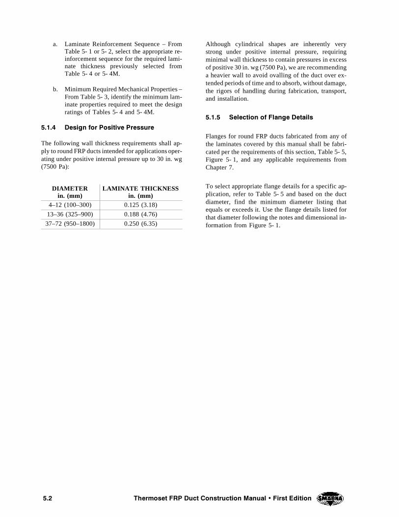
��� 4HERMOSET &20 $UCT #ONSTRUCTION -ANUAL � &IRST %DITION
a. Laminate Reinforcement Sequence – FromTable 5- 1 or 5- 2, select the appropriate re-inforcement sequence for the required lami-nate thickness previously selected fromTable 5- 4 or 5- 4M.
b. Minimum Required Mechanical Properties –From Table 5- 3, identify the minimum lam-inate properties required to meet the designratings of Tables 5- 4 and 5- 4M.
����� $ESIGN FOR 0OSITIVE 0RESSURE
The following wall thickness requirements shall ap-ply to round FRP ducts intended for applications oper-ating under positive internal pressure up to 30 in. wg(7500 Pa):
DIAMETERin. (mm)
LAMINATE THICKNESSin. (mm)
4–12 (100–300) 0.125 (3.18)
13–36 (325–900) 0.188 (4.76)
37–72 (950–1800) 0.250 (6.35)
Although cylindrical shapes are inherently verystrong under positive internal pressure, requiringminimal wall thickness to contain pressures in excessof positive 30 in. wg (7500 Pa), we are recommendinga heavier wall to avoid ovalling of the duct over ex-tended periods of time and to absorb, without damage,the rigors of handling during fabrication, transport,and installation.
����� 3ELECTION OF &LANGE $ETAILS
Flanges for round FRP ducts fabricated from any ofthe laminates covered by this manual shall be fabri-cated per the requirements of this section, Table 5- 5,Figure 5- 1, and any applicable requirements fromChapter 7.
To select appropriate flange details for a specific ap-plication, refer to Table 5- 5 and based on the ductdiameter, find the minimum diameter listing thatequals or exceeds it. Use the flange details listed forthat diameter following the notes and dimensional in-formation from Figure 5- 1.
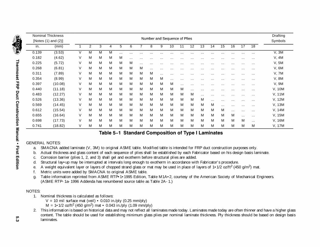
���7KHUP
RVHW
)53'XFW
&RQVWUX
FWLRQ0DQ
XDO
�)LUVW
(GLWLR
Q
Nominal ThicknessNumber and Sequence of Plies
Drafting
[Notes (1) and (2)]Number and Sequence of Plies
Symbols
in. (mm) 1 2 3 4 5 6 7 8 9 10 11 12 13 14 15 16 17 18
0.139 (3.53) V M M M ... ... ... ... ... ... ... ... ... ... ... ... ... ... V, 3M
0.182 (4.62) V M M M M ... ... ... ... ... ... ... ... ... ... ... ... ... V, 4M
0.225 (5.72) V M M M M M ... ... ... ... ... ... ... ... ... ... ... ... V, 5M
0.268 (6.81) V M M M M M M ... ... ... ... ... ... ... ... ... ... ... V, 6M
0.311 (7.89) V M M M M M M M ... ... ... ... ... ... ... ... ... ... V, 7M
0.354 (8.99) V M M M M M M M M ... ... ... ... ... ... ... ... ... V, 8M
0.397 (10.08) V M M M M M M M M M ... ... ... ... ... ... ... ... V, 9M
0.440 (11.18) V M M M M M M M M M M ... ... ... ... ... ... ... V, 10M
0.483 (12.27) V M M M M M M M M M M M ... ... ... ... ... ... V, 11M
0.526 (13.36) V M M M M M M M M M M M M ... ... ... ... ... V, 12M
0.569 (14.45) V M M M M M M M M M M M M M ... ... ... ... V, 13M
0.612 (15.54) V M M M M M M M M M M M M M M ... ... ... V, 14M
0.655 (16.64) V M M M M M M M M M M M M M M M ... ... V, 15M
0.698 (17.73) V M M M M M M M M M M M M M M M M ... V, 16M
0.741 (18.82) V M M M M M M M M M M M M M M M M M V, 17M
7DEOH �ï� 6WDQGDUG &RPSRVLWLRQ RI 7\SH , /DPLQDWHV
GENERAL NOTES:a. SMACNA added laminate (V, 3M) to original ASME table. Modified table is intended for FRP duct construction purposes only.b. Actual thickness and glass content of each sequence of plies shall be established by each Fabricator based on his design basis laminate.c. Corrosion barrier (plies 1, 2, and 3) shall gel and exotherm before structural plies are added.d. Structural lay• up may be interrupted at intervals long enough to exotherm in accordance with Fabricator' s procedure.e. A weight equivalent layer or layers of chopped strand glass or mat may be used in place of layers of 1• 1/2 oz/ft2 (450 g/m2) mat.f. Metric units were added by SMACNA to original ASME table.g. Table information reprinted from ASME RTP• 1• 1995 Edition, Table M1A• 2, courtesy of the American Society of Mechanical Engineers.
(ASME RTP- 1a- 1996 Addenda has renumbered source table as Table 2A- 1.)
NOTES:1. Nominal thickness is calculated as follows:
V = 10 mil surface mat (veil) • 0.010 in./ply (0.25 mm/ply)M = 1• 1/2 oz/ft2 (450 g/m2) mat • 0.043 in./ply (1.09 mm/ply)
2. This information is based on historical data and may not reflect all laminates made today. Laminates made today are often thinner and have a higher glasscontent. The table should be used for establishing minimum glass plies per nominal laminate thickness. Ply thickness should be based on design basislaminates.

���7KHUP
RVHW
)53'XFW
&RQVWUX
FWLRQ0DQ
XDO
�)LUVW
(GLWLR
Q
Nominal Thickness[N (1) d (2)] Number and Sequence of Plies
Drafting[Notes (1) and (2)] Number and Sequence of Plies
Symbols
in. (mm) 1 2 3 4 5 6 7 8 9 10 11 12 13 14 15 16 17 18 19 20
0.215 (5.46) V M M M R M ... ... ... ... ... ... ... ... ... ... ... ... ... ... V, 2M, MRM
0.291 (7.39) V M M M R M R M ... ... ... ... ... ... ... ... ... ... ... ... V, 2M, 2(MR)M
0.367 (9.32) V M M M R M R M R M ... ... ... ... ... ... ... ... ... ... V, 2M, 3(MR)M
0.410 (10.41) V M M M R M R M R M M ... ... ... ... ... ... ... ... ... V, 2M, 3(MR)M, M
0.486 (12.34) V M M M R M R M R M M R M ... ... ... ... ... ... ... V, 2M, 3(MR)M, MRM
0.562 (14.27) V M M M R M R M R M M R M R M ... ... ... ... ... V, 2M, 3(MR)M, 2(MR)M
0.638 (16.21) V M M M R M R M R M M R M R M R M ... ... ... V, 2M, 3(MR)M, 3(MR)M
0.681 (17.29) V M M M R M R M R M M R M R M R M M ... ... V, 2M, 3(MR)M, 3(MR)M,M
0.757 (19.23) V M M M R M R M R M M R M R M R M M R M V, 2M, 3(MR)M, 3(MR)M, MRM
7DEOH �ï� 6WDQGDUG &RPSRVLWLRQ RI 7\SH ,, /DPLQDWHV
GENERAL NOTES:a. Actual thickness and glass content of each sequence of plies shall be established by each Fabricator based on his design basis laminate.b. Corrosion barrier (plies 1, 2, and 3) shall gel and exotherm before structural plies are added.c. Structural lay• up may be interrupted long enough to exotherm between adjacent MM" plies. If required by fabrication procedure, location of exotherm
plies (plies 10 and 17) may be shifted within the laminate body. No plies may be omitted.d. A weight equivalent layer or layers of chopped strand glass or mat may be used in place of layers of 1• 1/2 oz/ft2 (450 g/m2) mat.e. Metric units were added by SMACNA to original ASME table.f. Table information reprinted from ASME RTP• 1• 1995 Edition, Table M1A• 3, courtesy of the American Society of Mechanical Engineers.
(ASME RTP- 1a- 1996 Addenda has renumbered source table as Table 2A- 2.)
NOTES:1. Nominal thickness is calculated as follows:
V = 10 mil surface mat (veil) • 0.010 in./ply (0.25 mm/ply)M = 1• 1/2 oz/ft2 (450 g/m2) mat • 0.043 in./ply (1.09 mm/ply)R = 24 oz/yd2 (810 g/m2) woven roving • 0.033 in./ply (0.84 mm/ply)
2. This information is based on historical data and may not reflect all laminates made today. Laminates made today are often thinner and have a higher glasscontent. The table should be used for establishing minimum glass plies per nominal laminate thickness. Ply thickness should be based on design basislaminates.
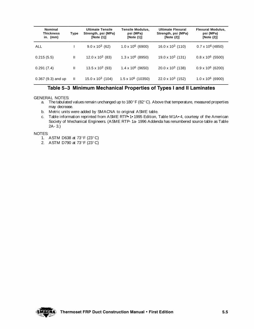
���7KHUPRVHW )53 'XFW &RQVWUXFWLRQ 0DQXDO � )LUVW (GLWLRQ
NominalThicknessin. (mm)
TypeUltimate Tensile
Strength, psi (MPa)[Note (1)]
Tensile Modulus,psi (MPa)[Note (1)]
Ultimate FlexuralStrength, psi (MPa)
[Note (2)]
Flexural Modulus,psi (MPa)[Note (2)]
ALL I 9.0 x 10³ (62) 1.0 x 10⁶ (6900) 16.0 x 10³ (110) 0.7 x 10⁶ (4850)
0.215 (5.5) II 12.0 x 10³ (83) 1.3 x 10⁶ (8950) 19.0 x 10³ (131) 0.8 x 10⁶ (5500)
0.291 (7.4) II 13.5 x 10³ (93) 1.4 x 10⁶ (9650) 20.0 x 10³ (138) 0.9 x 10⁶ (6200)
0.367 (9.3) and up II 15.0 x 10³ (104) 1.5 x 10⁶ (10350) 22.0 x 10³ (152) 1.0 x 10⁶ (6900)
7DEOH �ï� 0LQLPXP 0HFKDQLFDO 3URSHUWLHV RI 7\SHV , DQG ,, /DPLQDWHV
GENERAL NOTES:a. The tabulated values remain unchanged up to 180EF (82EC). Above that temperature, measured properties
may decrease.b. Metric units were added by SMACNA to original ASME table.c. Table information reprinted from ASME RTP• 1• 1995 Edition, Table M1A• 4, courtesy of the American
Society of Mechanical Engineers. (ASME RTP- 1a- 1996 Addenda has renumbered source table as Table2A- 3.)
NOTES:1. ASTM D638 at 73EF (23EC)2. ASTM D790 at 73EF (23EC)

���4HERM
OSET
&20$UCT
#ONSTRU
CTION-AN
UAL
�&IRST
%DITIO
N
�� FT 3UPPORT 3PAN 2OUND $UCT -IN� 3AFETY &ACTOR OF ���,!-).!4%3 490% ) 490% ))-ODULUS OF
%LASTICITY �%� PSI ��� X �� � ��� X �� � ��� X �� � ��� X �� � ��� X �� �
4HICKNESS �IN� ����� ����� ����� ����� ����� ����� ����� ����� ����� ����� ����� ����� �����$IAMETER �IN�
� ���� ��� ��� ��� ��� ��� ��� ��� ��� ���� ��� ��� ���� ���� ��� ��� ��� ��� ��� ��� ��� ��� ���� ��� ��� ���� ���� ��� ��� ��� ��� ��� ��� ��� ��� ���� ��� ��� ���� ���� ��� ��� ��� ��� ��� ��� ��� ��� ���� ��� ��� ����� ���� ���� ��� ��� ��� ��� ��� ��� ��� ���� ��� ��� ����� ���� ���� ��� ��� ��� ��� ��� ��� ��� ���� ��� ��� ����� ���� ���� ��� ��� ��� ��� ��� ��� ��� ���� ��� ��� ����� ���� ���� ���� ��� ��� ��� ��� ��� ��� ���� ��� ��� ����� ���� ���� ���� ��� ��� ��� ��� ��� ��� ���� ��� ��� ����� ��� ���� ���� ��� ��� ��� ��� ��� ��� ���� ��� ��� ����� ��� ���� ���� ���� ��� ��� ��� ��� ��� ���� ���� ��� ����� ��� ���� ���� ���� ��� ��� ��� ��� ��� ���� ���� ��� ����� ��� ���� ���� ���� ���� ��� ��� ��� ��� ���� ���� ��� ����� .2 ��� ���� ���� ���� ��� ��� ��� ��� ���� ���� ��� ����� .2 ��� ���� ���� ���� ��� ��� ��� ��� ���� ���� ��� ����� .2 ��� ���� ���� ���� ���� ��� ��� ��� ���� ���� ���� ����� .2 ��� ��� ���� ���� ���� ���� ��� ��� ���� ���� ���� ����� .2 .2 ��� ���� ���� ���� ���� ��� ��� ��� ���� ���� ����� .2 .2 ��� ��� ���� ���� ���� ���� ��� ��� ���� ���� ����� .2 .2 ��� ��� ���� ���� ���� ���� ��� ��� ���� ���� ������ .2 .2 .2 ��� ���� ���� ���� ���� ���� ��� ���� ���� ����
4ABLE � � .EGATIVE 0RESSURE 2ATINGS OF 4YPES ) � )) ,AMINATES IN IN� WG
NOTES:a. Cells marked NR (Not Rated) represent diameter and laminate combinations not covered by this table.b. Cells marked ... represent diameter and laminate combinations beyond the scope of this manual. They are more than adequate at the maximum rating
of 30 in. wg but become economically less attractive with increasing thickness.c. To select Type I and II laminates for Positive pressure systems, see section 5.1.4.

���4HERM
OSET
&20$UCT
#ONSTRU
CTION-AN
UAL
�&IRST
%DITIO
N
���� MM 3UPPORT 3PAN 2OUND $UCT -IN� 3AFETY &ACTOR OF ���,!-).!4%3 490% ) 490% ))
-ODULUS OF%LASTICITY �%� +0A ��� X �� � ��� X �� � ��� X �� � ���� X �� � ���� X �� �
4HICKNESS �MM ���� ���� ���� ���� ���� ���� ����� ����� ����� ���� ���� ���� �����$IAMETER �MM
��� ���� ��� ��� ��� ��� ��� ��� ��� ��� ���� ��� ��� ������ ���� ��� ��� ��� ��� ��� ��� ��� ��� ���� ��� ��� ������ ���� ��� ��� ��� ��� ��� ��� ��� ��� ���� ��� ��� ������ ���� ��� ��� ��� ��� ��� ��� ��� ��� ���� ��� ��� ������ ���� ���� ��� ��� ��� ��� ��� ��� ��� ���� ��� ��� ������ ���� ���� ��� ��� ��� ��� ��� ��� ��� ���� ��� ��� ������ ���� ���� ��� ��� ��� ��� ��� ��� ��� ���� ��� ��� ������ ���� ���� ���� ��� ��� ��� ��� ��� ��� ���� ��� ��� ������ ���� ���� ���� ��� ��� ��� ��� ��� ��� ���� ��� ��� ������ ���� ���� ���� ��� ��� ��� ��� ��� ��� ���� ��� ��� ������ ���� ���� ���� ���� ��� ��� ��� ��� ��� ���� ���� ��� ������ ���� ���� ���� ���� ��� ��� ��� ��� ��� ���� ���� ��� ������ ���� ���� ���� ���� ���� ��� ��� ��� ��� ���� ���� ��� ������ .2 ���� ���� ���� ���� ��� ��� ��� ��� ���� ���� ��� ������ .2 ���� ���� ���� ���� ��� ��� ��� ��� ���� ���� ��� ������� .2 ���� ���� ���� ���� ���� ��� ��� ��� ���� ���� ���� ������� .2 ���� ���� ���� ���� ���� ���� ��� ��� ���� ���� ���� ������� .2 .2 ���� ���� ���� ���� ���� ��� ��� ���� ���� ���� ������� .2 .2 ���� ���� ���� ���� ���� ���� ��� ���� ���� ���� ������� .2 .2 ���� ���� ���� ���� ���� ���� ��� ���� ���� ���� �������� .2 .2 .2 ���� ���� ���� ���� ���� ���� ���� ���� ���� ����
4ABLE � �- .EGATIVE 0RESSURE 2ATINGS OF 4YPES ) � )) ,AMINATES IN 0ANOTES:
a. Cells marked NR (Not Rated) represent diameter and laminate combinations not covered by this table.b. Cells marked ... represent diameter and laminate combinations beyond the scope of this manual. They are more than adequate at the maximum rating
of 30 in. wg but become economically less attractive with increasing thickness.c. To select Type I and II laminates for Positive pressure systems, see section 5.1.4.
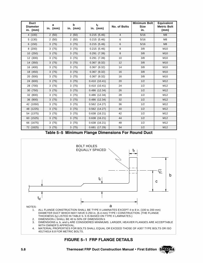
��� 7KHUPRVHW )53 'XFW &RQVWUXFWLRQ 0DQXDO � )LUVW (GLWLRQ
DuctDiameterin. (mm)
ain. (mm)
bin. (mm)
tfin. (mm) No. of Bolts
Minimum BoltSizein.
EquivalentMetric Bolt
(mm)
4 (100) 2 (50) 2 (50) 0.215 (5.46) 4 5/16 M8
5 (130) 2 (50) 2 (50) 0.215 (5.46) 6 5/16 M8
6 (150) 3 (75) 3 (75) 0.215 (5.46) 6 5/16 M8
8 (200) 3 (75) 3 (75) 0.215 (5.46) 8 3/8 M10
10 (250) 3 (75) 3 (75) 0.291 (7.39) 8 3/8 M10
12 (300) 3 (75) 3 (75) 0.291 (7.39) 10 3/8 M10
14 (350) 3 (75) 3 (75) 0.367 (9.32) 12 3/8 M10
16 (400) 3 (75) 3 (75) 0.367 (9.32) 14 3/8 M10
18 (450) 3 (75) 3 (75) 0.367 (9.32) 16 3/8 M10
20 (500) 3 (75) 3 (75) 0.367 (9.32) 16 3/8 M10
24 (600) 3 (75) 3 (75) 0.410 (10.41) 20 1/2 M12
28 (700) 3 (75) 3 (75) 0.410 (10.41) 24 1/2 M12
30 (750) 3 (75) 3 (75) 0.486 (12.34) 26 1/2 M12
32 (800) 3 (75) 3 (75) 0.486 (12.34) 28 1/2 M12
36 (900) 3 (75) 3 (75) 0.486 (12.34) 32 1/2 M12
42 (1050) 3 (75) 3 (75) 0.562 (14.27) 36 1/2 M12
48 (1225) 3 (75) 3 (75) 0.562 (14.27) 40 1/2 M12
54 (1375) 3 (75) 3 (75) 0.638 (16.21) 42 1/2 M12
60 (1525) 3 (75) 3 (75) 0.638 (16.21) 44 1/2 M12
66 (1675) 3 (75) 3 (75) 0.638 (16.21) 48 1/2 M12
72 (1825) 3 (75) 3 (75) 0.681 (17.29) 54 1/2 M12
7DEOH �ï� 0LQLPXP )ODQJH 'LPHQVLRQV )RU 5RXQG 'XFW
),*85( �ï� )53 )/$1*( '(7$,/6
BOLT HOLESEQUALLY SPACED WI
WI
WG
D
E
F
NOTES:1. ALL FLANGE CONSTRUCTION SHALL BE TYPE II LAMINATES EXCEPT 4 to 8 in. (100 to 200 mm)
DIAMETER DUCT WHICH MAY HAVE 0.250 in. (6.4 mm) TYPE I CONSTRUCTION. (THE FLANGETHICKNESS (tf) LISTED IN TABLE 5- 5 IS BASED ON TYPE II LAMINATES.)
2. DIMENSION c SHALL BE 40 to 50% OF DIMENSION b3. DIMENSIONS a, b, and tf ARE CONSIDERED MINIMUMS. LARGER, HEAVIER FLANGES ARE ACCEPTABLE
WITH OWNER’S APPROVAL.4. MATERIAL PROPERTIES FOR BOLTS SHALL EQUAL OR EXCEED THOSE OF A307 TYPE BOLTS OR ISO
4017/4014 8.8 FOR METRIC BOLTS.

���4HERMOSET &20 $UCT #ONSTRUCTION -ANUAL � &IRST %DITION
��� $%3)'. /& 2/5.$ &20 $5#43 53 ).' &),!-%.4 7/5.$ �490% 8,!-).!4%3
����� )NTRODUCTION
The design procedures and fabrication requirementsdescribed in this chapter apply to round (cylindrical)FRP ducts, intended for positive and negative pres-sure (vacuum) systems, operating in corrosive envi-ronments at temperatures up to 180^F (82^C) andfabricated from laminates based on thermoset polyes-ter resins having a heat deflection temperature (HDT)of 180^F (82^C) or higher. Higher temperature ap-plications require special premium grade resins ex-hibiting higher HDT’s to suit the higher temperaturerequirements based on the resin manufacturer’s rec-ommendations for such service.
FRP ducts fabricated per the requirements of this sec-tion shall be fabricated by contact molding methodsusing Filament Wound (Type X) laminates as de-scribed in Chapter 3.
����� -INIMUM ,AMINATE 0HYSICAL #HARAC TERISTICS
The composite structure for each laminate combina-tion and their corresponding nominal thickness arelisted in Table 5- 6. The minimum required physicalcharacteristics for Filament Wound (Type X) lami-nates are listed in Table 5- 7.
����� $ESIGN FOR .EGATIVE 0RESSURE�6ACUUM
For the practical application of the tables in this sec-tion, it suffices to say that Tables 5- 9 and 5- 9M listthe maximum recommended operating negative pres-sure for Filament Wound (Type X) laminates.
Note: For a detailed discussion of the developmentof the design tables contained in this manual, the as-sumptions and design concepts on which the ratingsare based, and the testing program which validatesthe results, see Appendix A.
The data in Tables 5- 9 and 5- 9M is arranged withthe Filament Wound (Type X) laminate combination(S1 through S13) heading the columns and a series ofduct diameters listed vertically, starting with thesmallest at 4 in. (100 mm) to the largest at 72 in. (1800mm).
The tables are based on two important assumptions:
a. the safety factor for each combination oflaminate thickness and diameter is equal toor greater than 4.0, and
b. the distance between supports is a maximumof 10 ft (3050 mm).
Typically, before selecting the required laminatethickness for a particular application, the system de-sign pressure (positive or negative), the duct diame-ter, and the laminate type are known.
������� 2EQUIRED ,AMINATE 4HICKNESS
To select the required laminate thickness, first deter-mine the system design pressure. If the system designpressure is positive, go to section 5.2.4. If the systemdesign pressure is negative, use either Table 5- 9 or5- 9M to complete the following steps:
a. Find the smallest diameter listing that equalsor exceeds the diameter of the duct underconsideration.
b. Move horizontally and find the minimumpressure rating that equals or exceeds thesystem design pressure.
c. Move vertically to the header of the columnand identify the corresponding laminatecombination.
������� ,AMINATE #ONSTRUCTION AND -INIMUM2EQUIRED -ECHANICAL 0ROPERTIES
To complete the selection of the basic constructionrequirements for FRP ducts fabricated from FilamentWound (Type X) laminates and operating under anegative design pressure, two more pieces of informa-tion must be identified:
a. Composite Laminate Structure – From Table5- 6, select the appropriate composite lami-nate structure corresponding to the laminatecombination previously selected from Table5- 9 or 5- 9M.
b. Minimum Required Mechanical Properties –From Table 5- 7, identify the minimum lam-inate mechanical properties required to meetthe design ratings of Tables 5- 9 and 5- 9M.
����� $ESIGN FOR 0OSITIVE 0RESSURE
The following wall thickness requirements shall ap-ply to round FRP ducts intended for applications oper-ating under positive internal pressure up to 30 in. wg(7500 Pa):

���� 4HERMOSET &20 $UCT #ONSTRUCTION -ANUAL � &IRST %DITION
DIAMETERin. (mm)
LAMINATECOMBINATION
LAMINATETHICKNESS
in. (mm)
4–12(100–300)
S10.140(3.56)
13–42(325–1050)
S30.180(4.57)
43–72(1075–1800)
S50.220(5.59)
Although cylindrical shapes are inherently verystrong under positive internal pressure, requiring
minimal wall thickness to contain pressures in excessof positive 30 in. wg (7500 Pa), we are recommendinga heavier wall to avoid ovalling of the duct over ex-tended periods of time and to absorb, without damage,the rigors of handling during fabrication, transport,and installation.
����� 3ELECTION OF &LANGE $ETAILS
For the selection of appropriate flange details for FRPducts fabricated from Filament Wound (Type X) lam-inates, refer to the table and selection procedure de-scribed in section 5.1.5.
#OMBINATION #OMPOSITE 3TRUCTURE 4OTAL 4HICKNESSIN� �MM
3� 6-- â � ,(7 ����� 4HICK ����� �����
3� 6-- â � ,(7 ����� 4HICK ����� �����
3� 6-- â � ,(7 ����� 4HICK ����� �����
3� 6-- â � ,(7 ����� 4HICK ����� �����
3� 6-- â �� ,(7 ����� 4HICK ����� �����
3�� 6-- â �� ,(7 ����� 4HICK ����� �����
3�� 6-- â �� ,(7 ����� 4HICK ����� �����
3�� 6-- â �� ,(7 ����� 4HICK ����� ������
3�� 6-- â �� ,(7 ����� 4HICK ����� ������
3�� 6-- â �� ,(7 ����� 4HICK ����� �����
3�� 6-- â �� ,(7 ����� 4HICK ����� ������
4ABLE � � &ILAMENT 7OUND �4YPE 8 #OMPOSITE ,AMINATES
NOTES:* VMM – corrosion liner – 0.100 in. (2.54 mm)** LHW – Layers Helix Winding – 0.020 in. (0.51 mm) per layer
Winding Angle between 60 and 70 degrees

����4HERMOSET &20 $UCT #ONSTRUCTION -ANUAL � &IRST %DITION
#OMBINATION 4HICKNESSIN� �MM
(OOP -ODULUSPSI �-0A
!XIAL -ODULUSPSI �-0A
3� ����� ����� ���� X ��� ������ ���� X ��� �����
3� ����� ����� ���� X ��� ������ ���� X ��� �����
3� ����� ����� ���� X ��� ������ ���� X ��� �����
3� ����� ����� ���� X ��� ������ ���� X ��� �����
3� ����� ����� ���� X ��� ������ ���� X ��� �����
3�� ����� ����� ���� X ��� ������ ���� X ��� �����
3�� ����� ����� ���� X ��� ������ ���� X ��� �����
3�� ����� ������ ���� X ��� ������ ���� X ��� �����
3�� ����� ������ ���� X ��� ������ ���� X ��� �����
3�� ����� ������ ���� X ��� ������ ���� X ��� �����
3�� ����� ������ ���� X ��� ������ ���� X ��� �����
4ABLE � � -INIMUM -ECHANICAL 0ROPERTIES OF&ILAMENT 7OUND �4YPE 8 ,AMINATES
#OMBINATION 7ALL4HICKNESS "OND #ONSTRUCTION
3� ����� ����� �ì ���� MM â -2--
3� ����� ����� �ì ���� MM â -2� �ì ���� MM â -2-
3� ����� ����� �ì ���� MM â -2� �ì ���� MM â -2--
3� ����� ����� �ì ���� MM â -2-� �ì ���� MM â -2--
3� ����� ����� �ì ���� MM â -2-� �ì ���� MM â -2-2-
3�� ����� ����� �ì ���� MM â -2-� �ì ���� MM â -2-2-
3�� ����� ����� �ì ���� MM â -2-� �ì ���� MM â -2-� �ì ���� MM â -2-
3�� ����� ������ �ì ���� MM â -2-� �ì ���� MM â -2-� �ì ���� MM â -2--
3�� ����� ������ �ì ���� MM â -2-� �ì ���� MM â -2-2� �ì ���� MM â -2--
3�� ����� ������ �ì ���� MM â -2-� �ì ���� MM â -2-2� �ì ���� MM â -2-2-
3�� ����� ������ �ì ���� MM â -2-� �ì ���� MM â -2-2� �ë ���� MM â -2-2--
4ABLE � � -INIMUM "OND #ONSTRUCTION FOR&ILAMENT 7OUND �4YPE 8 ,AMINATES
NOTES:a. Entire bond construction given in this table is to be placed on the exterior surface. Where possible, or for
duct diameters greater than 22 in. (550 mm), apply 6” (150 mm) MMVV on interior surface in additionto bonds shown in this table.
b. Apply 2 in. (50 mm) wide veil first on exterior surface if no bond is applied on interior surface.c. M = 1–1/2 oz/ft2 (450 g/m2) Matd. R = 24 oz/yd2 (810 g/m2) Woven Roving

����4HERM
OSET
&20$UCT
#ONSTRU
CTION-AN
UAL
�&IRST
%DITIO
N
�� FT 3UPPORT 3PAN 2OUND $UCT -IN� 3AFETY &ACTOR OF ���,!-).!4%3 3� 3� 3� 3� 3� 3�� 3��$IAMETER� IN�
� ���� ��� ��� ��� ��� ��� ���� ���� ��� ��� ��� ��� ��� ���� ���� ��� ��� ��� ��� ��� ���� ���� ��� ��� ��� ��� ��� ����� ���� ��� ��� ��� ��� ��� ����� ���� ��� ��� ��� ��� ��� ����� ���� ��� ��� ��� ��� ��� ����� ���� ���� ��� ��� ��� ��� ����� ���� ���� ��� ��� ��� ��� ����� ���� ���� ��� ��� ��� ��� ����� ���� ���� ���� ��� ��� ��� ����� ���� ���� ���� ��� ��� ��� ����� ���� ���� ���� ��� ��� ��� ����� ��� ���� ���� ���� ��� ��� ����� ��� ���� ���� ���� ��� ��� ����� ��� ���� ���� ���� ���� ��� ����� ��� ��� ���� ���� ���� ��� ����� .2 ��� ���� ���� ���� ���� ����� .2 ��� ���� ���� ���� ���� ����� .2 ��� ��� ���� ���� ���� ����� .2 ��� ��� ���� ���� ���� ����
4ABLE � � .EGATIVE 0RESSURE 2ATINGS OF &ILAMENT 7OUND �4YPE 8 ,AMINATES IN IN� WG
NOTES:a. Cells marked NR (Not Rated) represent diameter and laminate combinations not covered by this table.b. Cells marked ... represent diameter and laminate combinations beyond the scope of this manual. They are more than adequate at the maximum rating
of 30 in. wg but become economically less attractive with increasing thickness.c. To select Filament Wound (Type X) laminates for Positive pressure systems see section 5.2.4.
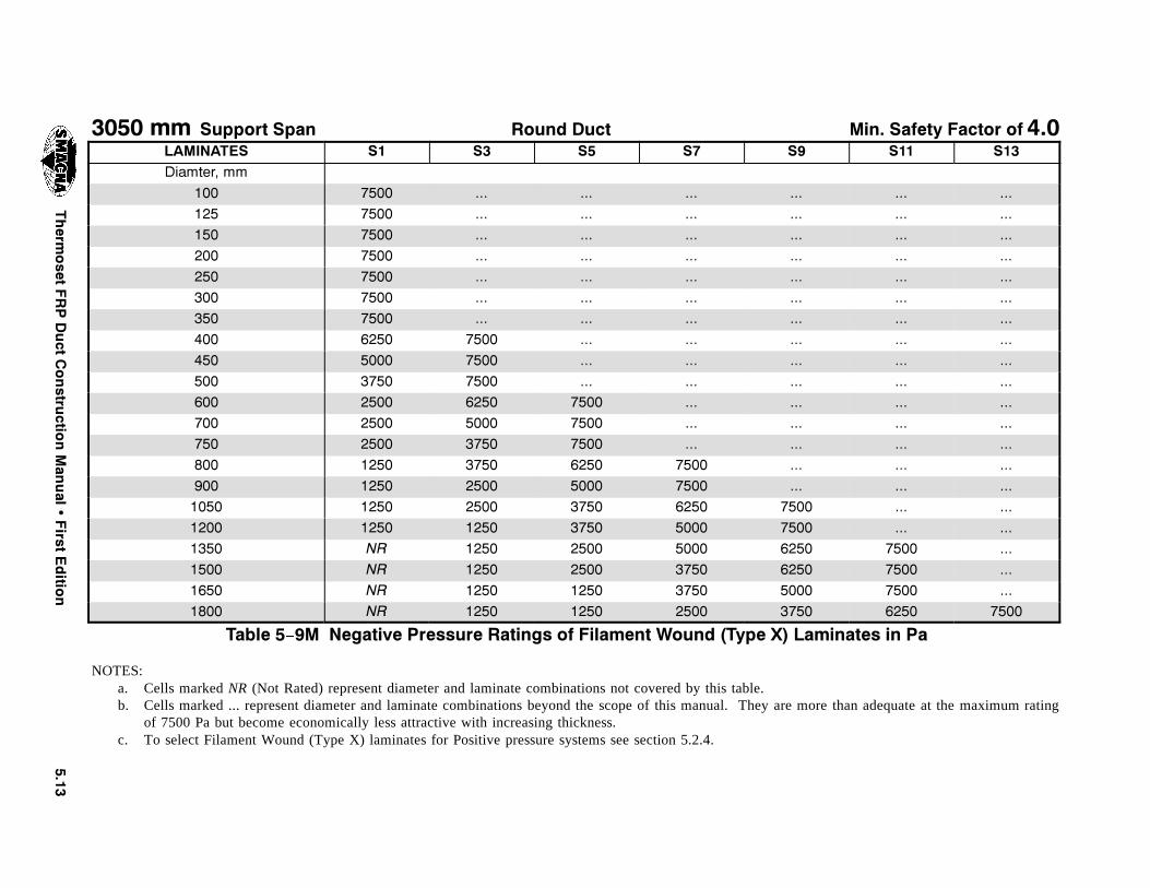
����4HERM
OSET
&20$UCT
#ONSTRU
CTION-AN
UAL
�&IRST
%DITIO
N
���� MM 3UPPORT 3PAN 2OUND $UCT -IN� 3AFETY &ACTOR OF ���,!-).!4%3 3� 3� 3� 3� 3� 3�� 3��$IAMTER� MM
��� ���� ��� ��� ��� ��� ��� ������ ���� ��� ��� ��� ��� ��� ������ ���� ��� ��� ��� ��� ��� ������ ���� ��� ��� ��� ��� ��� ������ ���� ��� ��� ��� ��� ��� ������ ���� ��� ��� ��� ��� ��� ������ ���� ��� ��� ��� ��� ��� ������ ���� ���� ��� ��� ��� ��� ������ ���� ���� ��� ��� ��� ��� ������ ���� ���� ��� ��� ��� ��� ������ ���� ���� ���� ��� ��� ��� ������ ���� ���� ���� ��� ��� ��� ������ ���� ���� ���� ��� ��� ��� ������ ���� ���� ���� ���� ��� ��� ������ ���� ���� ���� ���� ��� ��� ������� ���� ���� ���� ���� ���� ��� ������� ���� ���� ���� ���� ���� ��� ������� .2 ���� ���� ���� ���� ���� ������� .2 ���� ���� ���� ���� ���� ������� .2 ���� ���� ���� ���� ���� ������� .2 ���� ���� ���� ���� ���� ����
4ABLE � �- .EGATIVE 0RESSURE 2ATINGS OF &ILAMENT 7OUND �4YPE 8 ,AMINATES IN 0A
NOTES:a. Cells marked NR (Not Rated) represent diameter and laminate combinations not covered by this table.b. Cells marked ... represent diameter and laminate combinations beyond the scope of this manual. They are more than adequate at the maximum rating
of 7500 Pa but become economically less attractive with increasing thickness.c. To select Filament Wound (Type X) laminates for Positive pressure systems see section 5.2.4.

���� 7KHUPRVHW )53 'XFW &RQVWUXFWLRQ 0DQXDO � )LUVW (GLWLRQ
7+,6 3$*( ,17(17,21$//< /()7 %/$1.

CHAPTER 6
DESIGN OFRECTANGULAR FRP DUCT
#(!04%2 � $%3)'. /& 2%#4!.'5,!2 &20 $5#4
4HERMOSET &20 $UCT #ONSTRUCTION -ANUAL � &IRST %DITION ���
��� $%3)'. /& 2%#4!.'5,!2 &20$5#43 53).' 490% ) !.$ )) ,!-) .!4%3
����� ).42/$5#4)/.
The design procedures and fabrication requirementsdescribed in this chapter apply to rectangular FRPducts, intended for positive and negative (vacuum)pressure systems, operating in corrosive environ-ments at temperatures up to 180^F (82^C), and fabri-cated from laminates based on thermoset polyesterresins having a heat deflection temperature (HDT) of180^F (82^C) or higher.
Exception: Laminates fabricated from resin systemshaving an HDT of less than 180^F (82^C) may beused to fabricate FRP ducts designed using the proce-dures and tables contained in this manual providedthat the corrosion and operating temperature require-ments of the intended application can be met with theselected resin system.
Higher temperature applications require special pre-mium grade resins exhibiting HDT’s to suite the high-er temperature requirements. Resin selection shouldalways be based on the resin manufacturer’s recom-mendation for the specific application or service.
FRP ducts fabricated per the requirements of thischapter, shall be fabricated by hand lay–up or contactmolding methods, using Types I and II laminates asdescribed in Chapter 3.
Note: Filament Wound (Type X) rectangular ductsare not covered in this document.
����� -INIMUM ,AMINATE 0HYSICAL #HARAC TERISTICS
The number and sequence of fiberglass plies requiredfor each laminate type and thickness are listed inTables 5- 1 and 5- 2 for laminates Type I and II, re-spectively. The minimum required physical charac-teristics for both laminates are listed in Table 5- 3.
The physical characteristics of the design laminate,on which the duct fabrication is predicated, must meetor exceed the minimum values listed in Table 5- 3.Substantiation of laminate properties may be in theform of current or historical test records for the lami-nate under consideration. Tests supporting laminateproperties must have been performed per the require-ments of ASTM D638–96.
����� 3ELECTION OF ,AMINATE 4HICKNESS FOR%ITHER 0OSITIVE OR .EGATIVE 0RESSURE3YSTEMS
For the practical application of this chapter’s tablesit suffices to say that Tables 6- 1 through 6- 6 (Tables6- 1M through 6- 6M) list the laminate thickness andstiffener requirements for various rectangular ductsizes, at three pressure levels: 10, 20, and 30 in. wg.(2500, 5000, and 7500 Pa). There are separate tablesfor positive and negative pressure systems.
Note: For a detailed discussion of the developmentof the design tables contained in this manual, the as-sumptions and design concepts on which the ratingsare based, and the testing program which validatesthe results, see Appendix A.
The data in Tables 6- 1 through 6- 6 (Tables 6- 1Mthrough 6- 6M) is arranged starting with dimensionsrepresenting a rectangular duct listed in two contigu-ous columns. The first column represents the longestside and the second the short side. Duct sizes start at12 in. (300 mm) by 6 in. (150 mm) and increase to96 in. (2400 mm) square. Each series of duct sizesstarts with an incremental change in the longest–sidecolumn and a series of alternative sizes in the short–side column, increasing progressively from the small-est practical combination up to square. The table hasa fourth column which shows the maximum allow-able stiffener spacing for a particular duct size, whenstiffeners are required. A blank in the fourth columnindicates that the corresponding duct combination isan unstiffened design.
Typically, before selecting the required laminatethickness for a particular application the system de-sign pressure (positive or negative), the duct size, andthe laminate type are known.
������� 2EQUIRED ,AMINATE 4HICKNESS
To select the required laminate thickness for an ap-plication, follow these steps:
a. Based on the known system design pressure,select the appropriate table. For positivepressure systems go to Tables 6- 1 through6- 3 (Tables 6- 1M through 6- 3M), and fornegative pressure systems go to Tables 6- 4through 6- 6 (Tables 6- 4M through 6- 6M).
b. Enter the first column of the table and finda value that equals or exceeds the longestside of the rectangular duct.
��� 4HERMOSET &20 $UCT #ONSTRUCTION -ANUAL � &IRST %DITION
c. Move to the second column and find a valuethat equals or exceeds the short side of theduct.
d. Move horizontally to the third column andidentify the required laminate thickness.
Note: When selecting the required thicknessfor intermediate duct sizes, great care mustbe exercised to always select the higher lam-inate thickness. Sometimes this correspondsto the next higher duct size listed, and some-times it may correspond to the nearest lowersize listed. Always select the heavier lami-nate.
e. If your selection corresponds to an unstif-fened design (blank space in fourth column),you may want to consider a stiffened designthat will result in a lighter laminate thick-ness.
If so, identify the new required laminatethickness and note the listed maximum stiff-ener spacing. To select the appropriate stiff-ener construction, go to section 6.2. Keep inmind that the maximum stiffener spacingmust be based on the required laminatethickness just selected.
Note: An asterisk or two in the Shell–Thick-ness column indicates that one or two 6 in.
(150 mm) wide layers of mat reinforcementare required at the corners for that particu-lar duct size. This additional reinforcementis centered along each corner of the duct,and is applied to the entire length of the sec-tion. This technique, to stiffen the corners,permits the use of a lighter duct shell thanwould otherwise be possible. (See Figure6- 1.)
������� ,AMINATE #ONSTRUCTION AND -INIMUM2EQUIRED -ECHANICAL 0ROPERTIES
To complete the selection of the basic constructionrequirements for FRP ducts, two additional pieces ofinformation must be identified:
a. Laminate Reinforcement Sequence – FromTable 5- 1 or 5- 2, select the appropriate re-inforcement sequence for the required lami-nate thickness previously selected fromTables 6- 1 through 6- 3 (Tables 6- 1Mthrough 6- 3M) or Tables 6- 4 through 6- 6(Tables 6- 4M through 6- 6M).
b. Minimum Required Mechanical Properties –From Table 5- 3, identify the minimum lam-inate properties required to meet the designratings of Tables 6- 1 through 6- 3 (Tables6- 1M through 6- 3M) and Tables 6- 4through 6- 6 (Tables 6- 4M through 6- 6M).
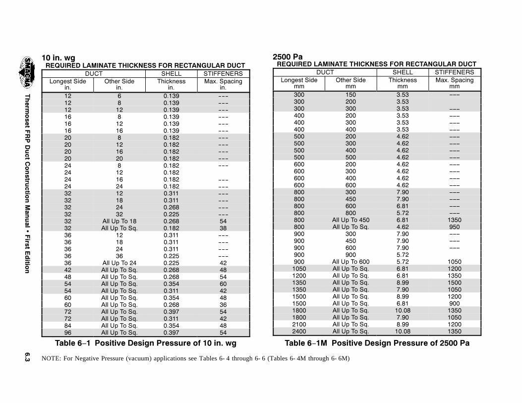
���4HERM
OSET
&20$UCT
#ONSTRU
CTION-AN
UAL
�&IRST
%DITIO
N
�� IN� WG2%15)2%$ ,!-).!4% 4()#+.%33 &/2 2%#4!.'5,!2 $5#4
$5#4 3(%,, 34)&&%.%23,ONGEST 3IDE
IN�/THER 3IDE
IN�4HICKNESS
IN�-AX� 3PACING
IN��� � ������� � ������� �� ������� � ������� �� ������� �� ������� � ������� �� ������� �� ������� �� ������� � ������� �� ������� �� ������� �� ������� �� ������� �� ������� �� ������� �� ������� !LL 5P 4O �� ����� ���� !LL 5P 4O 3Q� ����� ���� �� ������� �� ������� �� ������� �� ������� !LL 5P 4O �� ����� ���� !LL 5P 4O 3Q� ����� ���� !LL 5P 4O 3Q� ����� ���� !LL 5P 4O 3Q� ����� ���� !LL 5P 4O 3Q� ����� ���� !LL 5P 4O 3Q� ����� ���� !LL 5P 4O 3Q� ����� ���� !LL 5P 4O 3Q� ����� ���� !LL 5P 4O 3Q� ����� ���� !LL 5P 4O 3Q� ����� ���� !LL 5P 4O 3Q� ����� ��
4ABLE � � 0OSITIVE $ESIGN 0RESSURE OF �� IN� WG
���� 0A2%15)2%$ ,!-).!4% 4()#+.%33 &/2 2%#4!.'5,!2 $5#4
$5#4 3(%,, 34)&&%.%23,ONGEST 3IDE
MM/THER 3IDE
MM4HICKNESS
MM-AX� 3PACING
MM��� ��� ������� ��� ������� ��� ������� ��� ������� ��� ������� ��� ������� ��� ������� ��� ������� ��� ������� ��� ������� ��� ������� ��� ������� ��� ������� ��� ������� ��� ������� ��� ������� ��� ������� ��� ������� !LL 5P 4O ��� ���� ������� !LL 5P 4O 3Q� ���� ������ ��� ������� ��� ������� ��� ������� ��� ������� !LL 5P 4O ��� ���� �������� !LL 5P 4O 3Q� ���� �������� !LL 5P 4O 3Q� ���� �������� !LL 5P 4O 3Q� ���� �������� !LL 5P 4O 3Q� ���� �������� !LL 5P 4O 3Q� ���� �������� !LL 5P 4O 3Q� ���� ������� !LL 5P 4O 3Q� ����� �������� !LL 5P 4O 3Q� ���� �������� !LL 5P 4O 3Q� ���� �������� !LL 5P 4O 3Q� ����� ����
4ABLE � �- 0OSITIVE $ESIGN 0RESSURE OF ���� 0A
NOTE: For Negative Pressure (vacuum) applications see Tables 6- 4 through 6- 6 (Tables 6- 4M through 6- 6M)
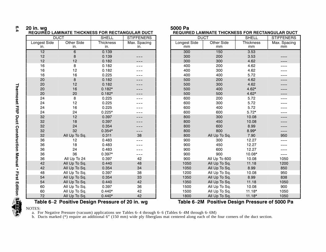
���4HERM
OSET
&20$UCT
#ONSTRU
CTION-AN
UAL
�&IRST
%DITIO
N
�� IN� WG2%15)2%$ ,!-).!4% 4()#+.%33 &/2 2%#4!.'5,!2 $5#4
$5#4 3(%,, 34)&&%.%23,ONGEST 3IDE
IN�/THER 3IDE
IN�4HICKNESS
IN�-AX� 3PACING
IN��� � ������� � ������� �� ������� � ������� �� ������� �� ������� � ������� �� ������� �� ������� �� ������� � ������� �� ������� �� ������� �� ������� �� ������� �� ������� �� ������� �� ������� !LL 5P 4O 3Q� ����� ���� �� ������� �� ������� �� ������� �� ������� !LL 5P 4O �� ����� ���� !LL 5P 4O 3Q� ����� ���� !LL 5P 4O 3Q� ����� ���� !LL 5P 4O 3Q� ����� ���� !LL 5P 4O 3Q� ����� ���� !LL 5P 4O 3Q� ����� ���� !LL 5P 4O 3Q� ����� ���� !LL 5P 4O 3Q� ����� ���� !LL 5P 4O 3Q� ����� ��
4ABLE � � 0OSITIVE $ESIGN 0RESSURE OF �� IN� WG
���� 0A2%15)2%$ ,!-).!4% 4()#+.%33 &/2 2%#4!.'5,!2 $5#4
$5#4 3(%,, 34)&&%.%23,ONGEST 3IDE
MM/THER 3IDE
MM4HICKNESS
MM-AX� 3PACING
MM��� ��� ������� ��� ������� ��� ������� ��� ������� ��� ������� ��� ������� ��� ������� ��� ������� ��� ������� ��� ������� ��� ������� ��� ������� ��� ������� ��� ������� ��� �������� ��� �������� ��� ������� ��� ������� !LL 5P 4O 3Q� ���� ������ ��� �������� ��� �������� ��� �������� ��� �������� !LL 5P 4O ��� ����� �������� !LL 5P 4O 3Q� ����� �������� !LL 5P 4O 3Q� ���� ������� !LL 5P 4O 3Q� ����� ������� !LL 5P 4O 3Q� ���� ������� !LL 5P 4O 3Q� ����� �������� !LL 5P 4O 3Q� ����� ������� !LL 5P 4O 3Q� ����� �������� !LL 5P 4O 3Q� ����� ����
4ABLE � �- 0OSITIVE $ESIGN 0RESSURE OF ���� 0ANOTES:
a. For Negative Pressure (vacuum) applications see Tables 6- 4 through 6- 6 (Tables 6- 4M through 6- 6M)b. Ducts marked (*) require an additional 6” (150 mm) wide ply fiberglass mat centered along each of the four corners of the duct section.
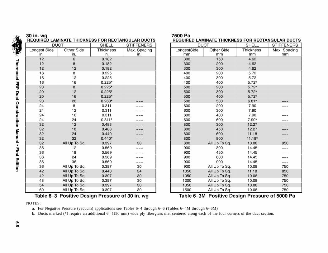
���4HERM
OSET
&20$UCT
#ONSTRU
CTION-AN
UAL
�&IRST
%DITIO
N
�� IN� WG2%15)2%$ ,!-).!4% 4()#+.%33 &/2 2%#4!.'5,!2 $5#43
$5#4 3(%,, 34)&&%.%23,ONGEST 3IDE
IN�/THER 3IDE
IN�4HICKNESS
IN�-AX� 3PACING
IN��� � ������� � ������� �� ������� � ������� �� ������� �� ������� � ������� �� ������� �� ������� �� ������� � ������� �� ������� �� ������� �� ������� �� ������� �� ������� �� ������� �� ������� !LL 5P 4O 3Q� ����� ���� �� ������� �� ������� �� ������� �� ������� !LL 5P 4O 3Q� ����� ���� !LL 5P 4O 3Q� ����� ���� !LL 5P 4O 3Q� ����� ���� !LL 5P 4O 3Q� ����� ���� !LL 5P 4O 3Q� ����� ���� !LL 5P 4O 3Q� ����� ��
4ABLE � � 0OSITIVE $ESIGN 0RESSURE OF �� IN� WG
���� 0A2%15)2%$ ,!-).!4% 4()#+.%33 &/2 2%#4!.'5,!2 $5#43
$5#4 3(%,, 34)&&%.%23,ONGEST3IDE
MM/THER 3IDE
MM4HICKNESS
MM-AX� 3PACING
MM��� ��� ������� ��� ������� ��� ������� ��� ������� ��� ������� ��� ������� ��� ������� ��� ������� ��� ������� ��� ������� ��� ������� ��� ������� ��� ������� ��� ������� ��� �������� ��� �������� ��� �������� ��� �������� !LL 5P 4O 3Q� ����� ������ ��� �������� ��� �������� ��� �������� ��� �������� !LL 5P 4O 3Q� ����� ������� !LL 5P 4O 3Q� ����� ������� !LL 5P 4O 3Q� ����� ������� !LL 5P 4O 3Q� ����� ������� !LL 5P 4O 3Q� ����� ������� !LL 5P 4O 3Q� ����� ���
4ABLE � �- 0OSITIVE $ESIGN 0RESSURE OF ���� 0ANOTES:
a. For Negative Pressure (vacuum) applications see Tables 6- 4 through 6- 6 (Tables 6- 4M through 6- 6M)b. Ducts marked (*) require an additional 6” (150 mm) wide ply fiberglass mat centered along each of the four corners of the duct section.

���4HERM
OSET
&20$UCT
#ONSTRU
CTION-AN
UAL
�&IRST
%DITIO
N
�� IN� WG2%15)2%$ ,!-).!4% 4()#+.%33 &/2 2%#4!.'5,!2 $5#4
$5#4 3(%,, 34)&&%.%23,ONGEST 3IDE
IN�/THER 3IDE
IN�4HICKNESS
IN�-AX� 3PACING
IN��� � ������� � ������� �� ������� � ������� �� ������� �� ������� � ������� �� ������� �� ������� �� ������� � ������� �� ������� �� ������� �� ������� �� ������� �� ������� �� ������� �� ������� !LL 5P 4O 3Q� ����� ���� !LL 5P 4O 3Q� ����� ���� �� ������� �� ������� �� ������� �� ������� !LL 5P 4O 3Q� ����� ���� !LL 5P 4O 3Q� ����� ���� !LL 5P 4O 3Q� ����� ���� !LL 5P 4O 3Q� ����� ���� !LL 5P 4O 3Q� ����� ���� !LL 5P 4O 3Q� ����� ���� !LL 5P 4O 3Q� ����� ���� !LL 5P 4O 3Q� ����� ���� !LL 5P 4O 3Q� ����� ���� !LL 5P 4O 3Q� ����� ���� !LL 5P 4O 3Q� ����� ��
4ABLE � � .EGATIVE $ESIGN 0RESSURE OF �� IN� WG
���� 0A2%15)2%$ ,!-).!4% 4()#+.%33 &/2 2%#4!.'5,!2 $5#4
$5#4 3(%,, 34)&&%.%23,ONGEST 3IDE
MM/THER 3IDE
MM4HICKNESS
MM-AX� 3PACING
MM��� ��� ������� ��� ������� ��� ������� ��� ������� ��� ������� ��� ������� ��� ������� ��� ������� ��� ������� ��� ������� ��� ������� ��� ������� ��� ������� ��� ������� ��� ������� ��� ������� ��� ������� ��� ������� !LL 5P 4O 3Q� ���� ������� !LL 5P 4O 3Q� ���� ������ ��� ������� ��� ������� ��� ������� ��� ������� !LL 5P 4O ��� ���� �������� !LL 5P 4O 3Q� ���� �������� !LL 5P 4O 3Q� ���� �������� !LL 5P 4O 3Q� ���� �������� !LL 5P 4O 3Q� ���� �������� !LL 5P 4O 3Q� ���� �������� !LL 5P 4O 3Q� ���� ������� !LL 5P 4O 3Q� ����� �������� !LL 5P 4O 3Q� ���� �������� !LL 5P 4O 3Q� ���� �������� !LL 5P 4O 3Q� ����� ����
4ABLE � �- .EGATIVE $ESIGN 0RESSURE OF ���� 0A
NOTE: For Positive Pressure applications see Tables 6- 1 through 6- 3 (Tables 6- 1M through 6- 3M)

���4HERM
OSET
&20$UCT
#ONSTRU
CTION-AN
UAL
�&IRST
%DITIO
N
�� IN� WG2%15)2%$ ,!-).!4% 4()#+.%33 &/2 2%#4!.'5,!2 $5#4
$5#4 3(%,, 34)&&%.%23,ONGEST 3IDE
IN�/THER 3IDE
IN�4HICKNESS
IN�-AX 3PACING
IN��� � ������� � ������� �� ������� � ������� �� ������� �� ������� � ������� �� ������� �� ������� �� ������� � ������� �� ������� �� ������� �� ������� �� ������� �� ������� �� ������� �� ������� !LL 5P 4O 3Q� ����� ���� �� ������� �� ������� �� ������� �� ������� !LL 5P 4O 3Q� ����� ���� !LL 5P 4O 3Q� ����� ���� !LL 5P 4O 3Q� ����� ���� !LL 5P 4O 3Q� ����� ���� !LL 5P 4O 3Q� ����� ���� !LL 5P 4O 3Q� ����� ���� !LL 5P 4O 3Q� ����� ���� !LL 5P 4O 3Q� ����� ���� !LL 5P 4O 3Q� ����� ��
4ABLE � � .EGATIVE $ESIGN 0RESSURE OF �� IN� WG
���� 0A2%15)2%$ ,!-).!4% 4()#+.%33 &/2 2%#4!.'5,!2 $5#4
$5#4 3(%,, 34)&&%.%23,ONGEST 3IDE
MM/THER 3IDE
MM4HICKNESS
MM-AX� 3PACING
MM��� ��� ������� ��� ������� ��� ������� ��� ������� ��� ������� ��� ������� ��� ������� ��� ������� ��� ������� ��� ������� ��� ������� ��� ������� ��� ������� ��� ������� ��� ������� ��� ������� ��� ������� ��� ������� !LL 5P 4O 3Q� ���� ������ ��� �������� ��� �������� ��� �������� ��� �������� !LL 5P 4O 3Q� ����� �������� !LL 5P 4O 3Q� ����� �������� !LL 5P 4O 3Q� ���� ������� !LL 5P 4O 3Q� ����� ������� !LL 5P 4O 3Q� ���� ������� !LL 5P 4O 3Q� ����� �������� !LL 5P 4O 3Q� ����� ������� !LL 5P 4O 3Q� ����� �������� !LL 5P 4O 3Q� ����� ����
4ABLE � �- .EGATIVE $ESIGN 0RESSURE OF ���� 0A
NOTES: a. For Positive Pressure applications see Tables 6- 1 through 6- 3 (Tables 6- 1M through 6- 3M)b. Ducts marked (*) require an additional 6” (150 mm) wide ply fiberglass mat centered along each of the four corners of the duct section.
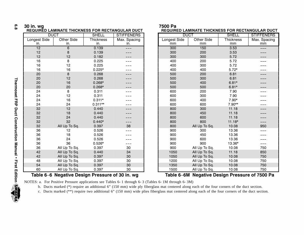
���4HERM
OSET
&20$UCT
#ONSTRU
CTION-AN
UAL
�&IRST
%DITIO
N
�� IN� WG2%15)2%$ ,!-).!4% 4()#+.%33 &/2 2%#4!.'5,!2 $5#4
$5#4 3(%,, 34)&&%.%23,ONGEST 3IDE
IN�/THER 3IDE
IN�4HICKNESS
IN�-AX� 3PACING
IN��� � ������� � ������� �� ������� � ������� �� ������� �� ������� � ������� �� ������� �� ������� �� ������� � ������� �� ������� �� ������� �� ������� �� ������� �� ������� �� ������� �� ������� !LL 5P 4O 3Q� ����� ���� �� ������� �� ������� �� ������� �� ������� !LL 5P 4O 3Q� ����� ���� !LL 5P 4O 3Q� ����� ���� !LL 5P 4O 3Q� ����� ���� !LL 5P 4O 3Q� ����� ���� !LL 5P 4O 3Q� ����� ���� !LL 5P 4O 3Q� ����� ��
4ABLE � � .EGATIVE $ESIGN 0RESSURE OF �� IN� WG
���� 0A2%15)2%$ ,!-).!4% 4()#+.%33 &/2 2%#4!.'5,!2 $5#4
$5#4 3(%,, 34)&&%.%23,ONGEST 3IDE
MM/THER 3IDE
MM4HICKNESS
MM-AX� 3PACING
MM��� ��� ������� ��� ������� ��� ������� ��� ������� ��� ������� ��� ������� ��� ������� ��� ������� ��� ������� ��� ������� ��� ������� ��� ������� ��� ������� ��� ������� ��� �������� ��� �������� ��� �������� ��� �������� !LL 5P 4O 3Q� ����� ������ ��� �������� ��� �������� ��� �������� ��� �������� !LL 5P 4O 3Q� ����� ������� !LL 5P 4O 3Q� ����� ������� !LL 5P 4O 3Q� ����� ������� !LL 5P 4O 3Q� ����� ������� !LL 5P 4O 3Q� ����� ������� !LL 5P 4O 3Q� ����� ���
4ABLE � �- .EGATIVE $ESIGN 0RESSURE OF ���� 0ANOTES: a. For Positive Pressure applications see Tables 6- 1 through 6- 3 (Tables 6- 1M through 6- 3M)
b. Ducts marked (*) require an additional 6” (150 mm) wide ply fiberglass mat centered along each of the four corners of the duct section.c. Ducts marked (**) require two additional 6” (150 mm) wide plies fiberglass mat centered along each of the four corners of the duct section.

���4HERMOSET &20 $UCT #ONSTRUCTION -ANUAL � &IRST %DITION
��� 3%,%#4)/. /& 34)&&%.%23 !.$&,!.'%3 &/2 2%#4!.'5,!2$5#4 3934%-3
����� )NTRODUCTION
Two basic stiffener designs can be considered for rec-tangular FRP ducts using Type II laminate construc-tion for bonding the stiffener “ribs” to the FRP ductshell:
a. Wood stiffener with 1/4 in. (6.4 mm) FRPbond
b. Semi–circular foam filler with 1/4 in. (6.4mm) FRP bond
Note: Other structural shapes of composite materialshaving equivalent structural properties as thoseshown on Tables 6- 8 through 6- 10 (Tables 6- 8Mthrough 6- 10M) may be substituted.
(However, because of the difference in thermal ex-pansion characteristics between metals and FRP, andthe possible corrosion problems they engender, metalstructural shapes are not recommended for stiffeningFRP duct.)
The stiffener tables cover three pressure levels 10, 20,and 30 in. wg (2500, 5000, and 7500 Pa), each tableis valid for both positive and negative pressure. Thetables list the maximum allowable span for each stiff-ener, based on three different design criteria: stressless than or equal to 2300 psi (333.6 kPa), a paneldeflection less than or equal to 3/4 in. (19.1 mm) orL/120, whichever is least. Within each pressure levelthere are separate tables for stiffener intervals (spac-ing) of 30, 36, 42, 48, and 54 in. (750, 900, 1050,1200, and 1350 mm).
����� 3ELECTION OF 3TIFFENERS FOR 2ECTANGU LAR $UCT 3YSTEMS
If the chosen design from section 6.1.3 requires stiff-eners, follow these steps for stiffener selection:
a. Based on the system design pressure andmaximum allowable stiffener spacing, selectthe appropriate stiffener table.
Note: For each stiffener the maximum allowable spancorresponding to each of the three design criteria arelisted. The value governing the design is the lower ofthe three and is bolded to simplify identification.
b. Enter the appropriate table and find a suit-able stiffener having a maximum stiffenerspan that exceeds the largest panel width(longest side) of the rectangular duct. (Thesame stiffener construction shall be used forboth, the long and the short sides of the duct.)
����� 3ELECTION OF &LANGES FOR 2ECTANGULAR$UCTS
Flanges shall be fabricated per the requirements ofthis section, including Table 6- 7, Figure 6- 5, and anyapplicable requirements from Chapter 7. Within thelimits indicated in the tables, flanges for rectangularFRP ducts shall be fabricated from Type II laminatesonly.
To select appropriate flange details for a specific ap-plication, refer to Table 6- 7. Corresponding to thelongest side of the duct in question, select values foreach of the dimensions referenced in Figure 6- 5. Tofinalize the flange details, follow the notes to Figure6- 5. The same flange dimensions selected for thelong side of the duct are also applicable to the shortside.
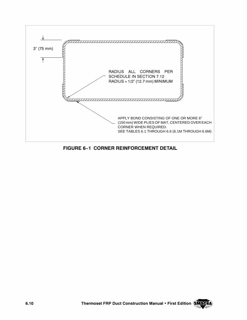
���� 7KHUPRVHW )53 'XFW &RQVWUXFWLRQ 0DQXDO � )LUVW (GLWLRQ
),*85( �ï� &251(5 5(,1)25&(0(17 '(7$,/
�µ ��� PP�
APPLY BOND CONSISTING OF ONE OR MORE 6"(150 mm) WIDE PLIES OF MAT, CENTERED OVER EACHCORNER WHEN REQUIRED.SEE TABLES 6.1 THROUGH 6.6 (6.1M THROUGH 6.6M)
5$',86 $// &251(56 3(56&+('8/( ,1 6(&7,21 ����5$',86 ���µ �����PP�0,1,080
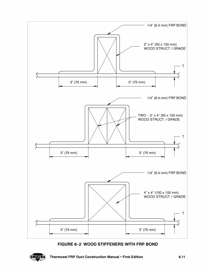
����4HERMOSET &20 $UCT #ONSTRUCTION -ANUAL � &IRST %DITION
&)'52% � � 7//$ 34)&&%.%23 7)4( &20 "/.$
���ì ���� MM &20 "/.$
���ì ���� MM &20 "/.$
���ì ���� MM &20 "/.$
�ì ��� MM �ì ��� MM
�ì ��� MM �ì ��� MM
�ì ��� MM �ì ��� MM
4
4
4
�ì X �ì ��� X ��� MM7//$ 3425#4� ) '2!$%
47/ â �ì X �ì ��� X ��� MM7//$ 3425#4� ) '2!$%
�ì X �ì ���� X ��� MM7//$ 3425#4� ) '2!$%

���� 4HERMOSET &20 $UCT #ONSTRUCTION -ANUAL � &IRST %DITION
&)'52% � � #/.3425#4)/. /& 42!.36%23% 34)&&%.%23
$%4!), ë!ì
$%4!), ë!ì
7(%. 53).' 7//$ !3 4(% &/2- &/2,!-).!4).' &20 34)&&%.%23� 4(%#/2.%23 -!9 "% "544%$ /2 -)4%2%$!.$ .!),%$ /2 3#2%7%$ !4 4(%%,%#4)/. /& 4(% $5#4 &!"2)#!4/2
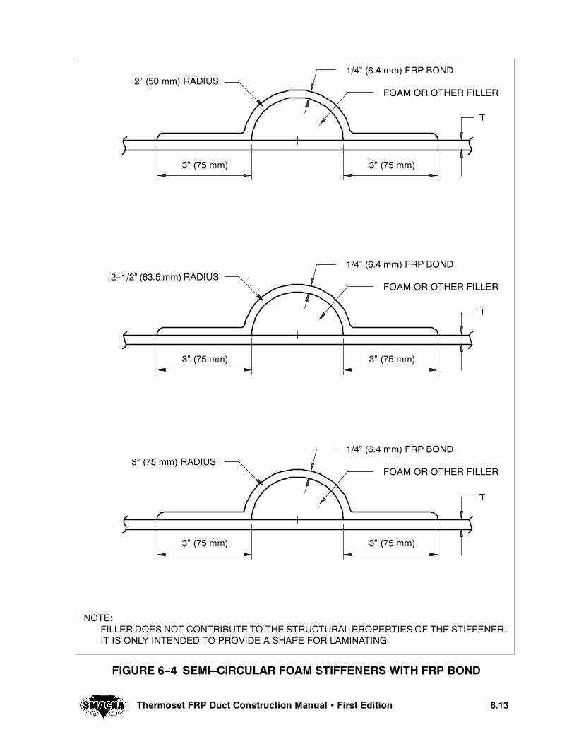
����4HERMOSET &20 $UCT #ONSTRUCTION -ANUAL � &IRST %DITION
&)'52% � � 3%-)â#)2#5,!2 &/!- 34)&&%.%23 7)4( &20 "/.$
���ì ���� MM &20 "/.$
�ì ��� MM
���ì ���� MM &20 "/.$
���ì ���� MM &20 "/.$
�ì ��� MM
�ì ��� MM �ì ��� MM
�ì ��� MM �ì ��� MM
&/!- /2 /4(%2 &),,%2
&/!- /2 /4(%2 &),,%2
&/!- /2 /4(%2 &),,%2
�â���ì ����� MM 2!$)53
�ì ��� MM 2!$)53
�ì ��� MM 2!$)53
./4%�&),,%2 $/%3 ./4 #/.42)"54% 4/ 4(% 3425#452!, 02/0%24)%3 /& 4(% 34)&&%.%2�)4 )3 /.,9 ).4%.$%$ 4/ 02/6)$% ! 3(!0% &/2 ,!-).!4).'

���� 7KHUPRVHW )53 'XFW &RQVWUXFWLRQ 0DQXDO � )LUVW (GLWLRQ
/RQJHVW 6LGH'LPHQVLRQLQ� �PP�
DLQ� �PP�
ELQ� �PP�
WILQ� �PP�
0D[� %ROW6SDFLQJLQ� �PP�
0LQLPXP%ROW 6L]H
LQ�
(TXLYDOHQW0HWULF %ROW
�PP�
�� ����� � ���� � ���� ����� ������ � ����� ��� 0�
�� ����� � ���� � ���� ����� ������ � ����� ��� 0�
�� ����� � ���� � ���� ����� ������ � ����� ��� 0�
�� ����� � ���� � ���� ����� ������� � ����� ��� 0��
�� ����� � ���� � ���� ����� ������� � ����� ��� 0��
�� ����� � ���� � ���� ����� ������� � ����� ��� 0��
�� ������ � ���� � ���� ����� ������� � ����� ��� 0��
�� ������ � ����� � ���� ����� ������� � ����� ��� 0��
�� ������ � ����� � ���� ����� ������� � ����� ��� 0��
�� ������ � ����� � ���� ����� ������� � ����� ��� 0��
�� ������ � ����� � ���� ����� ������� � ����� ��� 0��
�� ������ � ����� � ���� ����� ������� � ����� ��� 0��
�� ������ � ����� � ���� ����� ������� � ����� ��� 0��
7DEOH �ï� 0LQLPXP )ODQJH 'LPHQVLRQV )RU 5HFWDQJXODU 'XFW
),*85( �ï� )53 )/$1*( '(7$,/6
%2/7 +2/(6(48$//< 63$&(' WI
WI
WG
D
E
F
NOTES:1. ALL FLANGE CONSTRUCTION SHALL BE TYPE II LAMINATES. (THE FLANGE THICKNESS (tf) LISTED
IN TABLE 5- 5 IS BASED ON TYPE II LAMINATES.)2. DIMENSION c SHALL BE 40 to 50% OF DIMENSION b3. DIMENSIONS a, b, and tf ARE CONSIDERED MINIMUMS. LARGER, HEAVIER FLANGES ARE ACCEPTABLE
WITH OWNER’S APPROVAL.4. MATERIAL PROPERTIES FOR BOLTS SHALL EQUAL OR EXCEED THOSE OF A307 TYPE BOLTS OR ISO
4017/4014 8.8 FOR METRIC BOLTS.

����4HERMOSET &20 $UCT #ONSTRUCTION -ANUAL � &IRST %DITION
4()3 0!'% ).4%.4)/.!,,9 ,%&4 ",!.+
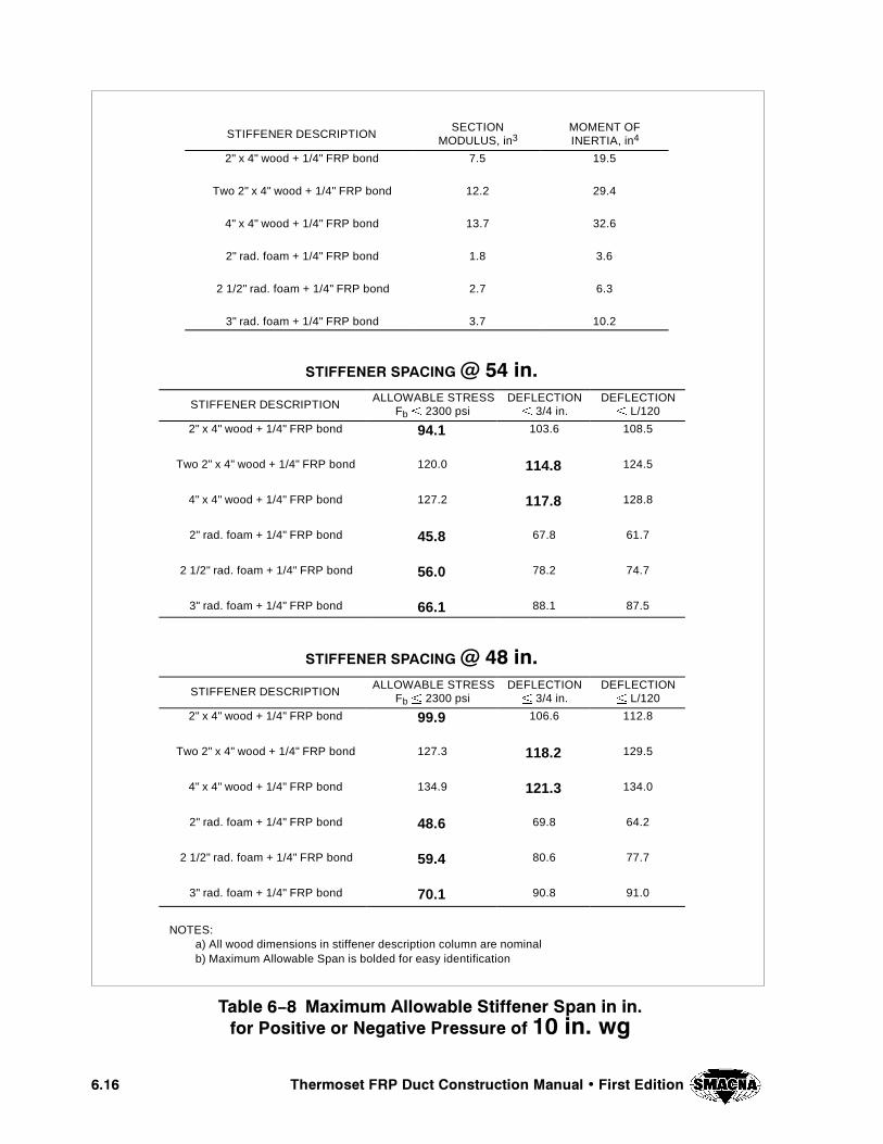
���� 7KHUPRVHW )53 'XFW &RQVWUXFWLRQ 0DQXDO � )LUVW (GLWLRQ
STIFFENER DESCRIPTIONSECTION
MODULUS, in3MOMENT OFINERTIA, in4
2" x 4" wood + 1/4" FRP bond 7.5 19.5
Two 2" x 4" wood + 1/4" FRP bond 12.2 29.4
4" x 4" wood + 1/4" FRP bond 13.7 32.6
2" rad. foam + 1/4" FRP bond 1.8 3.6
2 1/2" rad. foam + 1/4" FRP bond 2.7 6.3
3" rad. foam + 1/4" FRP bond 3.7 10.2
67,))(1(5 63$&,1* # �� LQ�
STIFFENER DESCRIPTIONALLOWABLE STRESS
Fb{ 2300 psiDEFLECTION{ 3/4 in.
DEFLECTION{ L/120
2" x 4" wood + 1/4" FRP bond 94.1 103.6 108.5
Two 2" x 4" wood + 1/4" FRP bond 120.0 114.8 124.5
4" x 4" wood + 1/4" FRP bond 127.2 117.8 128.8
2" rad. foam + 1/4" FRP bond 45.8 67.8 61.7
2 1/2" rad. foam + 1/4" FRP bond 56.0 78.2 74.7
3" rad. foam + 1/4" FRP bond 66.1 88.1 87.5
67,))(1(5 63$&,1* # �� LQ�
STIFFENER DESCRIPTIONALLOWABLE STRESS
Fb{ 2300 psiDEFLECTION{ 3/4 in.
DEFLECTION{ L/120
2" x 4" wood + 1/4" FRP bond 99.9 106.6 112.8
Two 2" x 4" wood + 1/4" FRP bond 127.3 118.2 129.5
4" x 4" wood + 1/4" FRP bond 134.9 121.3 134.0
2" rad. foam + 1/4" FRP bond 48.6 69.8 64.2
2 1/2" rad. foam + 1/4" FRP bond 59.4 80.6 77.7
3" rad. foam + 1/4" FRP bond 70.1 90.8 91.0
NOTES:a) All wood dimensions in stiffener description column are nominalb) Maximum Allowable Span is bolded for easy identification
7DEOH �ï� 0D[LPXP $OORZDEOH 6WLIIHQHU 6SDQ LQ LQ�IRU 3RVLWLYH RU 1HJDWLYH 3UHVVXUH RI �� LQ� ZJ
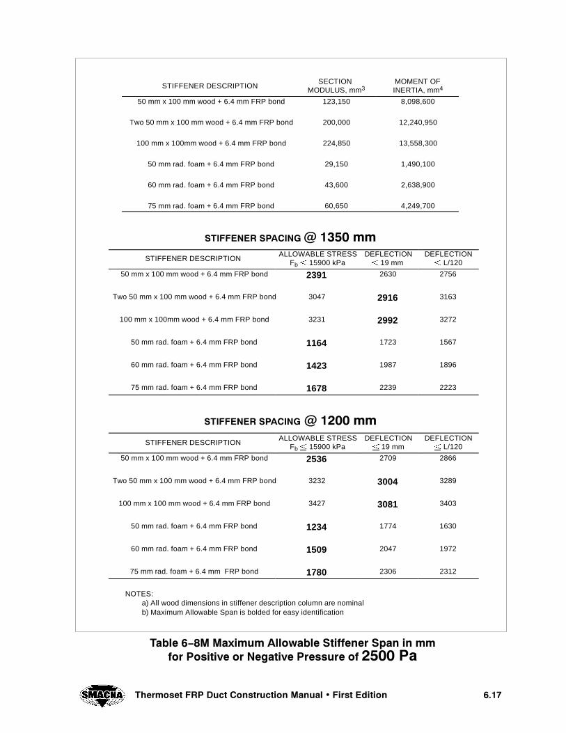
����7KHUPRVHW )53 'XFW &RQVWUXFWLRQ 0DQXDO � )LUVW (GLWLRQ
STIFFENER DESCRIPTIONSECTION
MODULUS, mm3MOMENT OFINERTIA, mm4
50 mm x 100 mm wood + 6.4 mm FRP bond 123,150 8,098,600
Two 50 mm x 100 mm wood + 6.4 mm FRP bond 200,000 12,240,950
100 mm x 100mm wood + 6.4 mm FRP bond 224,850 13,558,300
50 mm rad. foam + 6.4 mm FRP bond 29,150 1,490,100
60 mm rad. foam + 6.4 mm FRP bond 43,600 2,638,900
75 mm rad. foam + 6.4 mm FRP bond 60,650 4,249,700
67,))(1(5 63$&,1* # ���� PPSTIFFENER DESCRIPTION
ALLOWABLE STRESSFb{ 15900 kPa
DEFLECTION{ 19 mm
DEFLECTION{ L/120
50 mm x 100 mm wood + 6.4 mm FRP bond 2391 2630 2756
Two 50 mm x 100 mm wood + 6.4 mm FRP bond 3047 2916 3163
100 mm x 100mm wood + 6.4 mm FRP bond 3231 2992 3272
50 mm rad. foam + 6.4 mm FRP bond 1164 1723 1567
60 mm rad. foam + 6.4 mm FRP bond 1423 1987 1896
75 mm rad. foam + 6.4 mm FRP bond 1678 2239 2223
67,))(1(5 63$&,1* # ���� PP
STIFFENER DESCRIPTIONALLOWABLE STRESS
Fb{ 15900 kPaDEFLECTION{ 19 mm
DEFLECTION{ L/120
50 mm x 100 mm wood + 6.4 mm FRP bond 2536 2709 2866
Two 50 mm x 100 mm wood + 6.4 mm FRP bond 3232 3004 3289
100 mm x 100 mm wood + 6.4 mm FRP bond 3427 3081 3403
50 mm rad. foam + 6.4 mm FRP bond 1234 1774 1630
60 mm rad. foam + 6.4 mm FRP bond 1509 2047 1972
75 mm rad. foam + 6.4 mm FRP bond 1780 2306 2312
NOTES:a) All wood dimensions in stiffener description column are nominalb) Maximum Allowable Span is bolded for easy identification
7DEOH �ï�0 0D[LPXP $OORZDEOH 6WLIIHQHU 6SDQ LQ PPIRU 3RVLWLYH RU 1HJDWLYH 3UHVVXUH RI ���� 3D
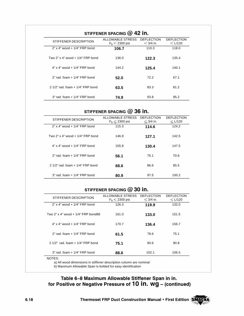
���� 7KHUPRVHW )53 'XFW &RQVWUXFWLRQ 0DQXDO � )LUVW (GLWLRQ
67,))(1(5 63$&,1* # �� LQ�STIFFENER DESCRIPTION
ALLOWABLE STRESSFb{ 2300 psi
DEFLECTION{ 3/4 in.
DEFLECTION{ L/120
2" x 4" wood + 1/4" FRP bond 106.7 110.3 118.0
Two 2" x 4" wood + 1/4" FRP bond 136.0 122.3 135.4
4" x 4" wood + 1/4" FRP bond 144.2 125.4 140.1
2" rad. foam + 1/4" FRP bond 52.0 72.2 67.1
2 1/2" rad. foam + 1/4" FRP bond 63.5 83.3 81.2
3" rad. foam + 1/4" FRP bond 74.9 93.8 95.2
67,))(1(5 63$&,1* # �� LQ�STIFFENER DESCRIPTION
ALLOWABLE STRESSFb{ 2300 psi
DEFLECTION{ 3/4 in.
DEFLECTION{ L/120
2" x 4" wood + 1/4" FRP bond 115.3 114.6 124.2
Two 2" x 4" wood + 1/4" FRP bond 146.9 127.1 142.5
4" x 4" wood + 1/4" FRP bond 155.8 130.4 147.5
2" rad. foam + 1/4" FRP bond 56.1 75.1 70.6
2 1/2" rad. foam + 1/4" FRP bond 68.6 86.6 85.5
3" rad. foam + 1/4" FRP bond 80.9 97.5 100.2
67,))(1(5 63$&,1* # �� LQ�STIFFENER DESCRIPTION
ALLOWABLE STRESSFb{ 2300 psi
DEFLECTION{ 3/4 in.
DEFLECTION{ L/120
2" x 4" wood + 1/4" FRP bond 126.3 119.9 132.0
Two 2" x 4" wood + 1/4" FRP bond88 161.0 133.0 151.5
4" x 4" wood + 1/4" FRP bond 170.7 136.4 156.7
2" rad. foam + 1/4" FRP bond 61.5 78.6 75.1
2 1/2" rad. foam + 1/4" FRP bond 75.1 90.6 90.8
3" rad. foam + 1/4" FRP bond 88.6 102.1 106.5
NOTES:a) All wood dimensions in stiffener description column are nominalb) Maximum Allowable Span is bolded for easy identification
7DEOH �ï� 0D[LPXP $OORZDEOH 6WLIIHQHU 6SDQ LQ LQ�IRU 3RVLWLYH RU 1HJDWLYH 3UHVVXUH RI �� LQ� ZJ ² �FRQWLQXHG�

����7KHUPRVHW )53 'XFW &RQVWUXFWLRQ 0DQXDO � )LUVW (GLWLRQ
67,))(1(5 63$&,1* # ���� PPSTIFFENER DESCRIPTION
ALLOWABLE STRESSFb{ 15900 kPa
DEFLECTION{ 19 mm
DEFLECTION{ L/120
50 mm x 100 mm wood + 6.4 mm FRP bond 2711 2801 2997
Two 50 mm x 100 mm wood + 6.4 mm FRP bond 3456 3105 3439
100 mm x 100 mm wood + 6.4 mm FRP bond 3664 3186 3558
50 mm rad. foam + 6.4 mm FRP bond 1320 1834 1704
60 mm rad. foam + 6.4 mm FRP bond 1613 2116 2062
75 mm rad. foam + 6.4 mm FRP bond 1903 2384 2417
67,))(1(5 63$&,1* # ��� PPSTIFFENER DESCRIPTION
ALLOWABLE STRESSFb{ 15900 kPa
DEFLECTION{ 19 mm
DEFLECTION{ L/120
50 mm x 100 mm wood + 6.4 mm FRP bond 2929 2911 3155
Two 50 mm x 100 mm wood + 6.4 mm FRP bond 3732 3227 3620
100 mm x 100 mm wood + 6.4 mm FRP bond 3957 3311 3746
50 mm rad. foam + 6.4 mm FRP bond 1425 1906 1794
60 mm rad. foam + 6.4 mm FRP bond 1742 2199 2171
75 mm rad. foam + 6.4 mm FRP bond 2055 2477 2545
67,))(1(5 63$&,1* # ��� PPSTIFFENER DESCRIPTION
ALLOWABLE STRESSFb{ 15900 kPa
DEFLECTION{ 19 mm
DEFLECTION{ L/120
50 mm x 100 mm wood + 6.4 mm FRP bond 3208 3047 3352
Two 50 mm x 100 mm wood + 6.4 mm FRP bond 4089 3378 3847
100 mm x 100 mm wood + 6.4 mm FRP bond 4335 3465 3981
50 mm rad. foam + 6.4 mm FRP bond 1561 1995 1907
60 mm rad. foam + 6.4 mm FRP bond 1909 2302 2307
75 mm rad. foam + 6.4 mm FRP bond 2251 2593 2704
NOTES:a) All wood dimensions in stiffener description column are nominalb) Maximum Allowable Span is bolded for easy identification
7DEOH �ï�0 0D[LPXP $OORZDEOH 6WLIIHQHU 6SDQ LQ PPIRU 3RVLWLYH RU 1HJDWLYH 3UHVVXUH RI ���� 3D ² �FRQWLQXHG�

���� 7KHUPRVHW )53 'XFW &RQVWUXFWLRQ 0DQXDO � )LUVW (GLWLRQ
STIFFENER DESCRIPTIONSECTION
MODULUS, mm3MOMENT OFINERTIA, mm3
2"x4" wood + 1/4" FRP bond 7.5 19.457
Two 2"x4" wood + 1/4" FRP bond 12.2 29.409
4"x4" wood + 1/4" FRP bond 13.7 32.574
2" rad. foam + 1/4" FRP bond 1.8 3.58
2 1/2" rad. foam + 1/4" FRP bond 2.7 6.34
3" rad. foam + 1/4" FRP bond 3.7 10.21
67,))(1(5 63$&,1* # �� LQ�
STIFFENER DESCRIPTIONALLOWABLE STRESS
Fb{ 2300 psiDEFLECTION{ 3/4 in
DEFLECTION{ L/120
2"x4" wood + 1/4" FRP bond 66.6 87.1 86.1
Two 2"x4" wood + 1/4" FRP bond 84.8 96.5 98.8
4"x4" wood + 1/4" FRP bond 89.9 99.0 102.3
2" rad. foam + 1/4" FRP bond 32.4 57.0 49.0
2 1/2" rad. foam + 1/4" FRP bond 39.6 65.8 59.3
3" rad. foam + 1/4" FRP bond 46.7 74.1 69.5
67,))(1(5 63$&,1* # �� LQ�STIFFENER DESCRIPTION
ALLOWABLE STRESSFb{ 2300 psi
DEFLECTION{ 3/4 in
DEFLECTION{ L/120
2"x4" wood + 1/4" FRP bond 70.6 89.7 89.6
Two 2"x4" wood + 1/4" FRP bond 90.0 99.4 102.8
4"x4" wood + 1/4" FRP bond 95.4 102.0 106.3
2" rad. foam + 1/4" FRP bond 34.4 58.7 50.9
2 1/2" rad. foam + 1/4" FRP bond 42.0 67.8 61.6
3" rad. foam + 1/4" FRP bond 49.5 76.3 72.2
NOTES:a) All wood dimensions in stiffener description column are nominalb) Maximum Allowable Span is bolded for easy identification
7DEOH �ï� 0D[LPXP $OORZDEOH 6WLIIHQHU 6SDQ LQ LQ�IRU 3RVLWLYH RU 1HJDWLYH 3UHVVXUH RI �� LQ� ZJ
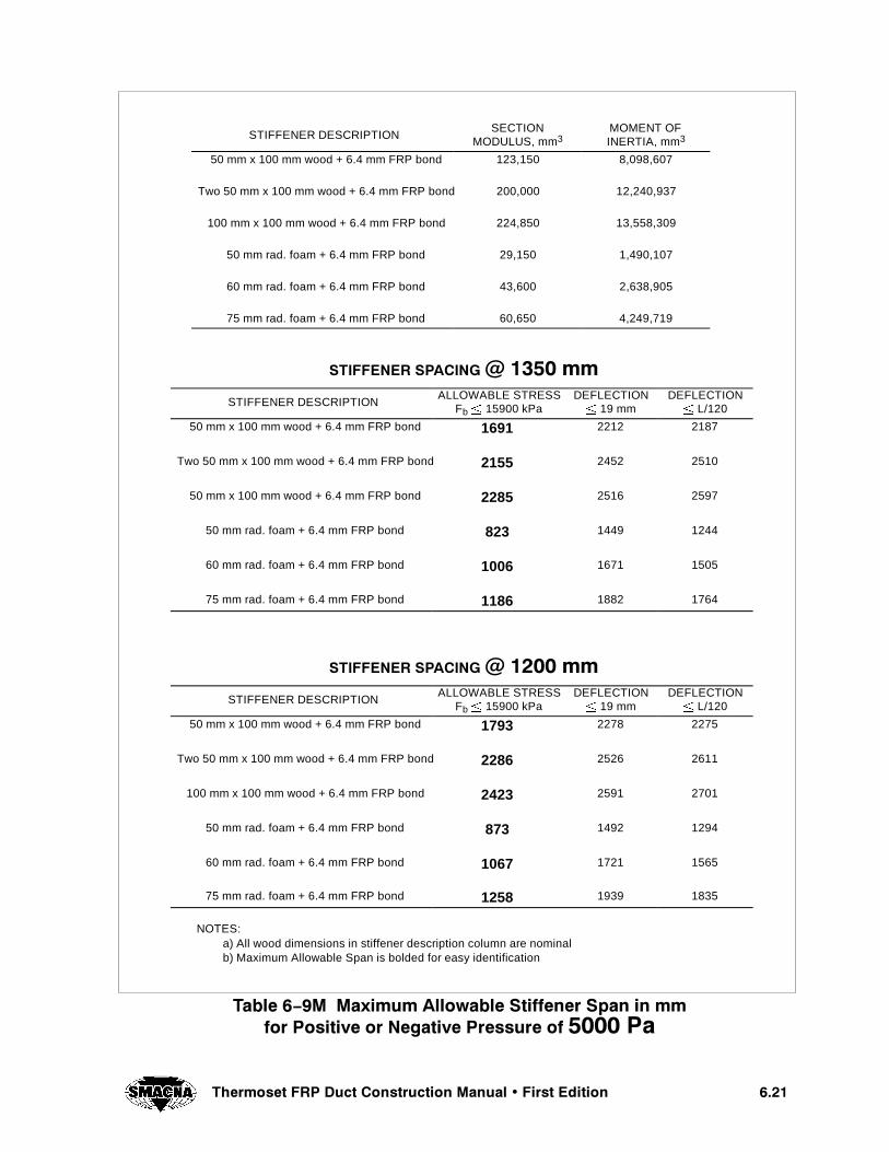
����7KHUPRVHW )53 'XFW &RQVWUXFWLRQ 0DQXDO � )LUVW (GLWLRQ
STIFFENER DESCRIPTIONSECTION
MODULUS, mm3MOMENT OFINERTIA, mm3
50 mm x 100 mm wood + 6.4 mm FRP bond 123,150 8,098,607
Two 50 mm x 100 mm wood + 6.4 mm FRP bond 200,000 12,240,937
100 mm x 100 mm wood + 6.4 mm FRP bond 224,850 13,558,309
50 mm rad. foam + 6.4 mm FRP bond 29,150 1,490,107
60 mm rad. foam + 6.4 mm FRP bond 43,600 2,638,905
75 mm rad. foam + 6.4 mm FRP bond 60,650 4,249,719
67,))(1(5 63$&,1* # ���� PPSTIFFENER DESCRIPTION
ALLOWABLE STRESSFb{ 15900 kPa
DEFLECTION{ 19 mm
DEFLECTION{ L/120
50 mm x 100 mm wood + 6.4 mm FRP bond 1691 2212 2187
Two 50 mm x 100 mm wood + 6.4 mm FRP bond 2155 2452 2510
50 mm x 100 mm wood + 6.4 mm FRP bond 2285 2516 2597
50 mm rad. foam + 6.4 mm FRP bond 823 1449 1244
60 mm rad. foam + 6.4 mm FRP bond 1006 1671 1505
75 mm rad. foam + 6.4 mm FRP bond 1186 1882 1764
67,))(1(5 63$&,1* # ���� PPSTIFFENER DESCRIPTION
ALLOWABLE STRESSFb{ 15900 kPa
DEFLECTION{ 19 mm
DEFLECTION{ L/120
50 mm x 100 mm wood + 6.4 mm FRP bond 1793 2278 2275
Two 50 mm x 100 mm wood + 6.4 mm FRP bond 2286 2526 2611
100 mm x 100 mm wood + 6.4 mm FRP bond 2423 2591 2701
50 mm rad. foam + 6.4 mm FRP bond 873 1492 1294
60 mm rad. foam + 6.4 mm FRP bond 1067 1721 1565
75 mm rad. foam + 6.4 mm FRP bond 1258 1939 1835
NOTES:a) All wood dimensions in stiffener description column are nominalb) Maximum Allowable Span is bolded for easy identification
7DEOH �ï�0 0D[LPXP $OORZDEOH 6WLIIHQHU 6SDQ LQ PPIRU 3RVLWLYH RU 1HJDWLYH 3UHVVXUH RI ���� 3D

���� 7KHUPRVHW )53 'XFW &RQVWUXFWLRQ 0DQXDO � )LUVW (GLWLRQ
67,))(1(5 63$&,1* # �� LQ�STIFFENER DESCRIPTION
ALLOWABLE STRESSFb{ 2300 psi
DEFLECTION{ 3/4 in
DEFLECTION{ L/120
2" x 4" wood + 1/4" FRP bond 75.5 92.7 93.6
Two 2" x 4" wood + 1/4" FRP bond 96.2 102.8 107.5
4" x 4" wood + 1/4" FRP bond 102.0 105.5 111.2
2" rad. foam + 1/4" FRP bond 36.7 60.7 53.3
2 1/2" rad. foam + 1/4" FRP bond 44.9 70.1 64.4
3" rad. foam + 1/4" FRP bond 53.0 78.9 75.5
67,))(1(5 63$&,1* # �� LQ�STIFFENER DESCRIPTION
ALLOWABLE STRESSFb{ 2300 psi
DEFLECTION{ 3/4 in
DEFLECTION{ L/120
2" x 4" wood + 1/4" FRP bond 81.5 96.4 98.6
Two 2" x 4" wood + 1/4" FRP bond 103.9 106.8 113.1
4" x 4" wood + 1/4" FRP bond 110.2 109.6 117.1
2" rad. foam + 1/4" FRP bond 39.7 63.1 56.1
2 1/2" rad. foam + 1/4" FRP bond 48.5 72.8 67.8
3" rad. foam + 1/4" FRP bond 57.2 82.0 79.5
67,))(1(5 63$&,1* # �� LQ�STIFFENER DESCRIPTION
ALLOWABLE STRESSFb{ 2300 psi
DEFLECTION{ 3/4 in
DEFLECTION{ L/120
2" x 4" wood + 1/4" FRP bond 89.3 100.9 104.8
Two 2" x 4" wood + 1/4" FRP bond 113.8 111.8 120.2
4" x 4" wood + 1/4" FRP bond 120.7 114.7 124.4
2" rad. foam + 1/4" FRP bond 43.5 66.1 59.6
2 1/2" rad. foam + 1/4" FRP bond 53.1 76.2 72.1
3" rad. foam + 1/4" FRP bond 62.7 85.8 84.5
NOTES:a) All wood dimensions in stiffener description column are nominalb) Maximum Allowable Span is bolded for easy identification
7DEOH �ï� $OORZDEOH 6WLIIHQHU 6SDQ LQ LQ�IRU 3RVLWLYH RU 1HJDWLYH 3UHVVXUH RI �� LQ� ZJ ² �FRQWLQXHG�

����7KHUPRVHW )53 'XFW &RQVWUXFWLRQ 0DQXDO � )LUVW (GLWLRQ
67,))(1(5 63$&,1* # ���� PPSTIFFENER DESCRIPTION
ALLOWABLE STRESSFb{ 15900 kPa
DEFLECTION{ 19 mm
DEFLECTION{ L/120
50 mm x 100 mm wood + 6.4 mm FRP bond 1917 2355 2378
Two 50 mm x 100 mm wood + 6.4 mm FRP bond 2443 2611 2730
100 mm x 100 mm wood + 6.4 mm FRP bond 2591 2679 2824
50 mm rad. foam + 6.4 mm FRP bond 933 1542 1353
60 mm rad. foam + 6.4 mm FRP bond 1141 1779 1637
75 mm rad. foam + 6.4 mm FRP bond 1345 2005 1918
67,))(1(5 63$&,1* # ��� PPSTIFFENER DESCRIPTION
ALLOWABLE STRESSFb{ 15900 kPa
DEFLECTION{ 19 mm
DEFLECTION{ L/120
50 mm x 100 mm wood + 6.4 mm FRP bond 2071 2448 2504
Two 50 mm x 100 mm wood + 6.4 mm FRP bond 2639 2714 2874
100 mm x 100 mm wood + 6.4 mm FRP bond 2798 2784 2973
50 mm rad. foam + 6.4 mm FRP bond 1008 1603 1424
60 mm rad. foam + 6.4 mm FRP bond 1232 1849 1723
75 mm rad. foam + 6.4 mm FRP bond 1453 2083 2020
67,))(1(5 63$&,1* # ��� PPSTIFFENER DESCRIPTION
ALLOWABLE STRESSFb{ 15900 kPa
DEFLECTION{ 19 mm
DEFLECTION{ L/120
50 mm x 100 mm wood + 6.4 mm FRP bond 2269 2562 2661
Two 50 mm x 100 mm wood + 6.4 mm FRP bond 2891 2841 3054
100 mm x 100 mm wood + 6.4 mm FRP bond 3065 2914 3159
50 mm rad. foam + 6.4 mm FRP bond 1104 1678 1513
60 mm rad. foam + 6.4 mm FRP bond 1350 1936 1831
75 mm rad. foam + 6.4 mm FRP bond 1592 2180 2146
NOTES:a) All wood dimensions in stiffener description column are nominalb) Maximum Allowable Span is bolded for easy identification
7DEOH �ï�0 0D[LPXP $OORZDEOH 6WLIIHQHU 6SDQV LQ PPIRU 3RVLWLYH RU 1HJDWLYH 3UHVVXUH RI ���� 3D ² �FRQWLQXHG�
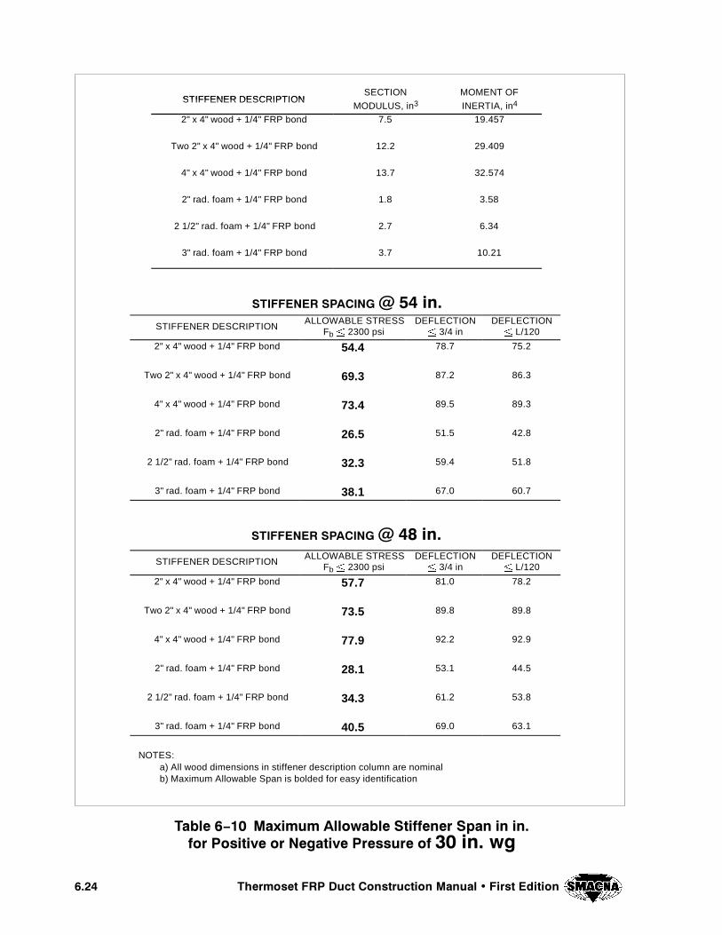
���� 7KHUPRVHW )53 'XFW &RQVWUXFWLRQ 0DQXDO � )LUVW (GLWLRQ
STIFFENER DESCRIPTIONSECTION MOMENT OF
STIFFENER DESCRIPTIONMODULUS, in3 INERTIA, in4
2" x 4" wood + 1/4" FRP bond 7.5 19.457
Two 2" x 4" wood + 1/4" FRP bond 12.2 29.409
4" x 4" wood + 1/4" FRP bond 13.7 32.574
2" rad. foam + 1/4" FRP bond 1.8 3.58
2 1/2" rad. foam + 1/4" FRP bond 2.7 6.34
3" rad. foam + 1/4" FRP bond 3.7 10.21
67,))(1(5 63$&,1* # �� LQ�STIFFENER DESCRIPTION
ALLOWABLE STRESSFb{ 2300 psi
DEFLECTION{ 3/4 in
DEFLECTION{ L/120
2" x 4" wood + 1/4" FRP bond 54.4 78.7 75.2
Two 2" x 4" wood + 1/4" FRP bond 69.3 87.2 86.3
4" x 4" wood + 1/4" FRP bond 73.4 89.5 89.3
2" rad. foam + 1/4" FRP bond 26.5 51.5 42.8
2 1/2" rad. foam + 1/4" FRP bond 32.3 59.4 51.8
3" rad. foam + 1/4" FRP bond 38.1 67.0 60.7
67,))(1(5 63$&,1* # �� LQ�STIFFENER DESCRIPTION
ALLOWABLE STRESSFb{ 2300 psi
DEFLECTION{ 3/4 in
DEFLECTION{ L/120
2" x 4" wood + 1/4" FRP bond 57.7 81.0 78.2
Two 2" x 4" wood + 1/4" FRP bond 73.5 89.8 89.8
4" x 4" wood + 1/4" FRP bond 77.9 92.2 92.9
2" rad. foam + 1/4" FRP bond 28.1 53.1 44.5
2 1/2" rad. foam + 1/4" FRP bond 34.3 61.2 53.8
3" rad. foam + 1/4" FRP bond 40.5 69.0 63.1
NOTES:a) All wood dimensions in stiffener description column are nominalb) Maximum Allowable Span is bolded for easy identification
7DEOH �� 0D[LPXP $OORZDEOH 6WLIIHQHU 6SDQ LQ LQ�IRU 3RVLWLYH RU 1HJDWLYH 3UHVVXUH RI �� LQ� ZJ

����7KHUPRVHW )53 'XFW &RQVWUXFWLRQ 0DQXDO � )LUVW (GLWLRQ
STIFFENER DESCRIPTIONSECTION MOMENT OF
STIFFENER DESCRIPTIONMODULUS, mm3 INERTIA, mm4
50 mm x 100 mm wood + 6.4 mm FRP bond 123,150 8,098,607
Two 50 mm x 100 mm wood + 6.4 mm FRP bond 200,000 12,240,937
100 mm x 100 mm wood + 6.4 mm FRP bond 224,850 13,558,309
50 mm rad. foam + 6.4 mm FRP bond 29,150 1,490,107
60 mm rad. foam + 6.4 mm FRP bond 43,600 2,638,905
75 mm rad. foam + 6.4 mm FRP bond 60,650 4,249,719
67,))(1(5 63$&,1* # ���� PPSTIFFENER DESCRIPTION
ALLOWABLE STRESSFb{ 15900 kPa
DEFLECTION{ 19 mm
DEFLECTION{ L/120
50 mm x 100 mm wood + 6.4 mm FRP bond 1381 1999 1911
Two 50 mm x 100 mm wood + 6.4 mm FRP bond 1759 2216 2193
100 mm x 100 mm wood + 6.4 mm FRP bond 1865 2273 2269
50 mm rad. foam + 6.4 mm FRP bond 672 1309 1087
60 mm rad. foam + 6.4 mm FRP bond 821 1510 1315
75 mm rad. foam + 6.4 mm FRP bond 969 1701 1541
67,))(1(5 63$&,1* # ���� PPSTIFFENER DESCRIPTION
ALLOWABLE STRESSFb{ 15900 kPa
DEFLECTION{ 19 mm
DEFLECTION{ L/120
50 mm x 100 mm wood + 6.4 mm FRP bond 1464 2058 1987
Two 50 mm x 100 mm wood + 6.4 mm FRP bond 1866 2282 2281
100 mm x 100 mm wood + 6.4 mm FRP bond 1979 2341 2360
50 mm rad. foam + 6.4 mm FRP bond 713 1348 1130
60 mm rad. foam + 6.4 mm FRP bond 871 1555 1368
75 mm rad. foam + 6.4 mm FRP bond 1027 1752 1603
NOTES:a) All wood dimensions in stiffener description column are nominalb) Maximum Allowable Span is bolded for easy identification
7DEOH ��0 0D[LPXP $OORZDEOH 6WLIIHQHU 6SDQ LQ PPIRU 3RVLWLYH RU 1HJDWLYH 3UHVVXUH RI ���� 3D
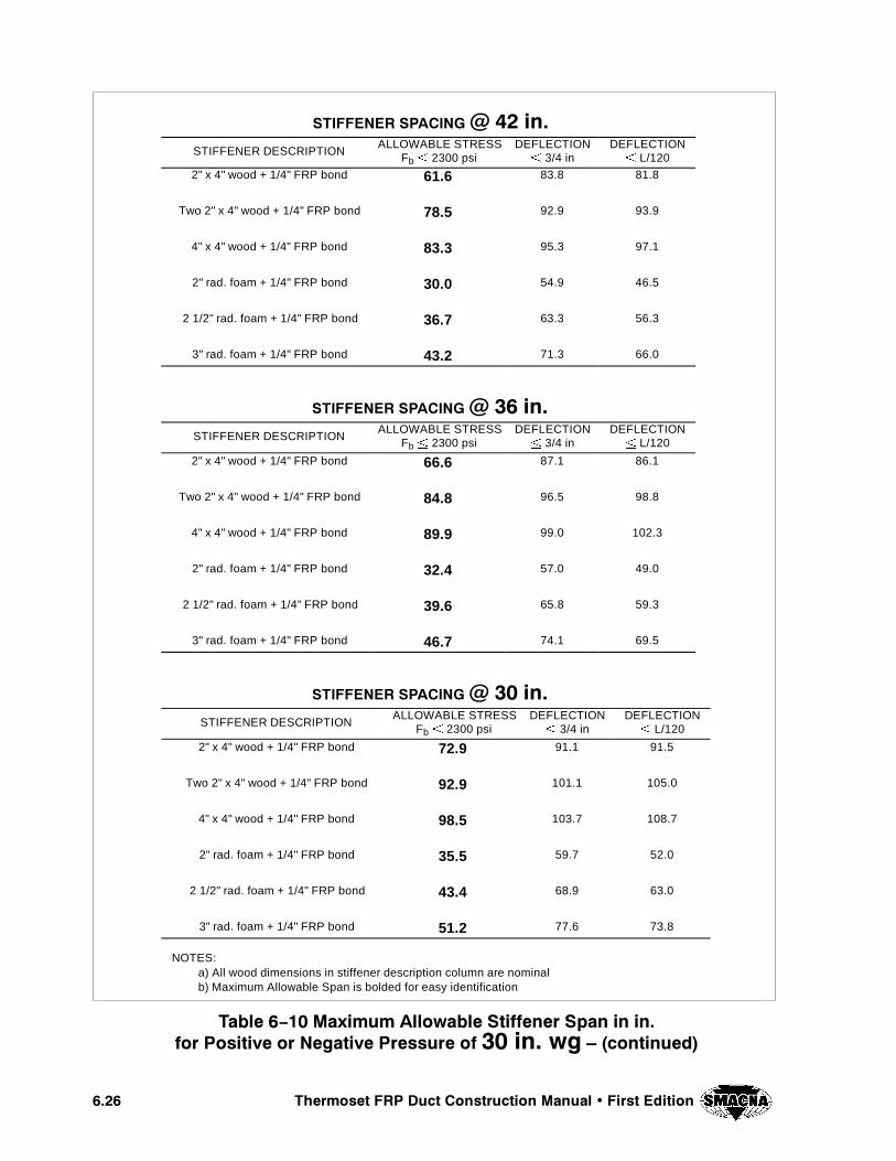
���� 7KHUPRVHW )53 'XFW &RQVWUXFWLRQ 0DQXDO � )LUVW (GLWLRQ
67,))(1(5 63$&,1* # �� LQ�STIFFENER DESCRIPTION
ALLOWABLE STRESSFb{ 2300 psi
DEFLECTION{ 3/4 in
DEFLECTION{ L/120
2" x 4" wood + 1/4" FRP bond 61.6 83.8 81.8
Two 2" x 4" wood + 1/4" FRP bond 78.5 92.9 93.9
4" x 4" wood + 1/4" FRP bond 83.3 95.3 97.1
2" rad. foam + 1/4" FRP bond 30.0 54.9 46.5
2 1/2" rad. foam + 1/4" FRP bond 36.7 63.3 56.3
3" rad. foam + 1/4" FRP bond 43.2 71.3 66.0
67,))(1(5 63$&,1* # �� LQ�STIFFENER DESCRIPTION
ALLOWABLE STRESSFb{ 2300 psi
DEFLECTION{ 3/4 in
DEFLECTION{ L/120
2" x 4" wood + 1/4" FRP bond 66.6 87.1 86.1
Two 2" x 4" wood + 1/4" FRP bond 84.8 96.5 98.8
4" x 4" wood + 1/4" FRP bond 89.9 99.0 102.3
2" rad. foam + 1/4" FRP bond 32.4 57.0 49.0
2 1/2" rad. foam + 1/4" FRP bond 39.6 65.8 59.3
3" rad. foam + 1/4" FRP bond 46.7 74.1 69.5
67,))(1(5 63$&,1* # �� LQ�STIFFENER DESCRIPTION
ALLOWABLE STRESSFb{ 2300 psi
DEFLECTION{ 3/4 in
DEFLECTION{ L/120
2" x 4" wood + 1/4" FRP bond 72.9 91.1 91.5
Two 2" x 4" wood + 1/4" FRP bond 92.9 101.1 105.0
4" x 4" wood + 1/4" FRP bond 98.5 103.7 108.7
2" rad. foam + 1/4" FRP bond 35.5 59.7 52.0
2 1/2" rad. foam + 1/4" FRP bond 43.4 68.9 63.0
3" rad. foam + 1/4" FRP bond 51.2 77.6 73.8
NOTES:a) All wood dimensions in stiffener description column are nominalb) Maximum Allowable Span is bolded for easy identification
7DEOH �ï�� 0D[LPXP $OORZDEOH 6WLIIHQHU 6SDQ LQ LQ�IRU 3RVLWLYH RU 1HJDWLYH 3UHVVXUH RI �� LQ� ZJ ² �FRQWLQXHG�
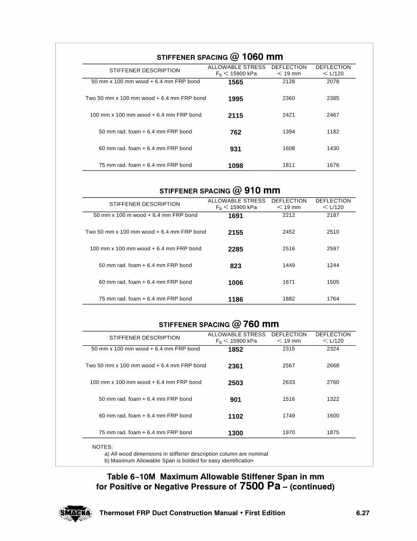
����7KHUPRVHW )53 'XFW &RQVWUXFWLRQ 0DQXDO � )LUVW (GLWLRQ
67,))(1(5 63$&,1* # ���� PPSTIFFENER DESCRIPTION
ALLOWABLE STRESSFb{ 15900 kPa
DEFLECTION{ 19 mm
DEFLECTION{ L/120
50 mm x 100 mm wood + 6.4 mm FRP bond 1565 2128 2078
Two 50 mm x 100 mm wood + 6.4 mm FRP bond 1995 2360 2385
100 mm x 100 mm wood + 6.4 mm FRP bond 2115 2421 2467
50 mm rad. foam + 6.4 mm FRP bond 762 1394 1182
60 mm rad. foam + 6.4 mm FRP bond 931 1608 1430
75 mm rad. foam + 6.4 mm FRP bond 1098 1811 1676
67,))(1(5 63$&,1* # ��� PPSTIFFENER DESCRIPTION
ALLOWABLE STRESSFb{ 15900 kPa
DEFLECTION{ 19 mm
DEFLECTION{ L/120
50 mm x 100 m wood + 6.4 mm FRP bond 1691 2212 2187
Two 50 mm x 100 mm wood + 6.4 mm FRP bond 2155 2452 2510
100 mm x 100 mm wood + 6.4 mm FRP bond 2285 2516 2597
50 mm rad. foam + 6.4 mm FRP bond 823 1449 1244
60 mm rad. foam + 6.4 mm FRP bond 1006 1671 1505
75 mm rad. foam + 6.4 mm FRP bond 1186 1882 1764
67,))(1(5 63$&,1* # ��� PPSTIFFENER DESCRIPTION
ALLOWABLE STRESSFb{ 15900 kPa
DEFLECTION{ 19 mm
DEFLECTION{ L/120
50 mm x 100 mm wood + 6.4 mm FRP bond 1852 2315 2324
Two 50 mm x 100 mm wood + 6.4 mm FRP bond 2361 2567 2668
100 mm x 100 mm wood + 6.4 mm FRP bond 2503 2633 2760
50 mm rad. foam + 6.4 mm FRP bond 901 1516 1322
60 mm rad. foam + 6.4 mm FRP bond 1102 1749 1600
75 mm rad. foam + 6.4 mm FRP bond 1300 1970 1875
NOTES:a) All wood dimensions in stiffener description column are nominalb) Maximum Allowable Span is bolded for easy identification
7DEOH �ï��0 0D[LPXP $OORZDEOH 6WLIIHQHU 6SDQ LQ PPIRU 3RVLWLYH RU 1HJDWLYH 3UHVVXUH RI ���� 3D ² �FRQWLQXHG�

���� 4HERMOSET &20 $UCT #ONSTRUCTION -ANUAL � &IRST %DITION
4()3 0!'% ).4%.4)/.!,,9 ,%&4 ",!.+

CHAPTER 7
REQUIREMENTS
#(!04%2 � 2%15)2%-%.43
���4HERMOSET &20 $UCT #ONSTRUCTION -ANUAL � &IRST %DITION
��� 4%2-)./,/'9
Unless otherwise indicated, the plastics terminologyused in this manual shall be in accordance with thedefinitions given in ASTM D883.
��� #/.4!#4 -/,$).'
Includes the application of glass plies in sheet formby the hand lay–up and spray–up methods of fabrica-tion. Fiberglass roving is chopped and blown onto themold. The resin can be sprayed or poured andbrushed, and rolled to wet the fiber and eliminate airvoid entrapment.
��� -!4%2)!,3
Resin shall be a commercial–grade thermoset that hasbeen tested in accordance with ASTM C581 or thathas been previously documented to be acceptable forthe service conditions. Where no test or service infor-mation is available, the end user shall agree to selecta suitable resin with the fabricator.
The resin may contain fillers or thixotropic agents asapproved by the resin manufacturer. When required,fire retardant synergists may also be added to the resinto reduce flame spread.
��� 34/2!'%
All resin, glass reinforcement, and curing agents sup-plied for joining FRP duct in the field, must be storedin a clean, dry, cool area to maximize their shelf life.
��� 34!4)# %,%#42)#)49
Grounding requirements, if any, shall be determinedby the end–user and the FRP duct fabricator.
��� 2%).&/2#%-%.4
The reinforcing material shall be a commercial gradeof glass with a suitable binder, and sizing compatiblewith the resin to be used.
These symbols are used to represent different typesof glass reinforcement:
M = 1–1/2 oz/ft2 (450 g/m2) chopped strand mat
R = 24 oz/yd2 (810 g/m2) woven roving
V = veil – glass or synthetic, 0.010 in./ply(0.25 mm/ply) calculated thickness
��� 2!7 %$'%3
All cut edges, drilled holes, and spot faces shall becoated with catalyzed resin containing wax, and UVadditives if duct systems may be exposed to weather-ing. To prevent chemical attack, voids and crevicesshall be filled and sealed so that no glass fibers areexposed.
��� */).43 �7%,$3 /2 "/.$3
Finished joints shall be built up with successive layersof FRP and be as strong as the pieces being joined.Crevices between joined pieces shall be filled with athixotropic paste, leaving a smooth inner surface.Where required, the interior of the joint shall be cov-ered with two plies of mat and finished with one layerof veil and one coat of paraffinated resin. The weldshall be centered on the joint within 1/2 in. (12.7 mm).Gaps between duct ends shall be as close as possiblebut in no case exceed 3/8 in. (9.5 mm). See Tables5- 8 and 7- 5 for minimum bond construction.
��� ,!-).!4% #/.3425#4)/.
Laminate construction shall be generally as describedin Chapter 3. More specifically, laminate construc-tion shall follow the lay–up sequence correspondingto the standard laminate compositions for Types I andII laminates, as listed in Tables 5- 1 and 5- 2, or inTable 5- 6 for Filament Wound (Type X) laminates.
����� !PPEARANCE
The corrosion barrier laminate shall be free of visualdefects, such as foreign inclusions, dry spots, airbubbles, pinholes, pimples, and delamination as de-fined by ASTM–2563, Level II. The remainder of thelaminate (outer structural portion) shall be free ofvisual defects to the extent commercially practicable.Additionally, the exterior surface shall be smooth andresin rich with no dry fibers visible. All raw cuts shallbe resin coated to prevent moisture absorption. (Seesection 7.7.)
����� 3URFACE (ARDNESS
The laminate shall exhibit an average surface hard-ness of at least 90% of the resin manufacturer’s pub-lished Barcol hardness for the cured resin. (See sec-tion 8.1.4 for detailed requirements and test methods.)
Exception: Laminate surfaces finished with syntheticveil and resin are considered adequately cured whenthe average hardness, established as describedabove, equals or exceeds 80% of the Barcol hardness
��� 4HERMOSET &20 $UCT #ONSTRUCTION -ANUAL � &IRST %DITION
value established by the resin manufacturer for thecured resin.
���� $%3)'. 2%15)2%-%.43
Minimum duct specifications shall be in accordancewith the requirements of either Chapter 5 – Designof Round FRP Duct or Chapter 6 – Design of Rectan-gular FRP Duct.
NOTE: Duct design does not include consideration ofwind, snow, ice, maintenance, or seismic loads. Nordoes it include loads resulting from the accumulationof particulates, condensate, or other liquids (e.g.sprinkler water).
������ $IMENSIONS
Standard duct and fitting dimensions are based on in-side dimensions.
������ 3HOP $RAWINGS AND $ESIGN #ALCULA TIONS
FRP duct and hoods shall be fabricated in accordancewith the design and construction details shown inshop drawings and design calculations as approved bythe purchaser.
������ 2EQUIRED ,AMINATE 4HICKNESS
Required laminate thickness is defined as the thick-ness obtained from Tables 5- 4 (5- 4M) or 5- 6 forround ducts, and Tables 6- 1 through 6- 3 (6- 1Mthrough 6- 3M) for rectangular ducts.
Nominal laminate thickness is the thickness of a stan-dard laminate that equals or exceeds the required lam-inate thickness. Nominal thickness for standard lami-nate compositions of Types I and II laminates arelisted in Tables 5- 1 and 5- 2. For laminate combina-tions of filament wound (Type X) laminates the corre-sponding nominal thickness are listed in Table 5- 6.
������ ,AMINATE 4HICKNESS 4OLERANCE
To meet the requirements of this manual, a laminatemust:
R Contain the required number of layers ofglass as listed in Tables 5- 1 and 5- 2 forTypes I and II laminates, or Table 5- 6 forfilament wound (Type X).
R Exhibit an average thickness not less than85%, nor more than 120%, of the requiredthickness, based on the average of six read-ings taken at random.(See section 8.1.5 formore details on methodology for establish-ing average thickness, and thickness limits.)
���� /6%2,!0
All reinforcing materials shall be layed–up staggered,such that adjoining plies overlap by 1/2 in. (15 mm)minimum with respect to the overlap of precedingplies.
���� 2%#4!.'5,!2 $5#4 #/2.%23
Interior corners shall be formed to a radius based onthe following schedule:
Widest Adjoining Panelin. (mm)
Corner Radiusin. (mm)
24 (600) and under 0.500 (15)
25 to 48 (625 to 1200) 1.0 (25)
49 (1225) and larger 1.5 (40)
When required by the notes to Tables 6- 1 through6- 6 (6- 1M through 6- 6M), one or more 6 in. (150mm) wide layers of fiberglass mat are bonded withresin to each of the four corners of the duct for im-proved rigidity. This additional layer (or layers) of re-inforcement are centered over each corner, and ex-tend the full length of the duct section. (See TableFigure 6- 1.)
���� "/.$ #/.3425#4)/.
The bond construction for field–wrapping duct jointsshall use the same type of resin used in fabricating theduct, and shall follow the same lay–up sequence toproduce a bond thickness at least equal to that speci-fied for the duct and exhibit a minimum taper of 6:1.(See Table 7- 5 and Figure 7- 6.)
Exception: When joining filament wound duct, thelay–up sequence shall be based on a special Type IIlaminate composition designed to meet or exceed thestrength of the filament wound duct. (See Table 5- 8for specific requirements.)
���� &,!.'% 2%15)2%-%.43
������ &LANGE #ONSTRUCTION
Flange construction shall be Type I (small round ductonly, see Figure 5- 1) or Type II, hand laid–up in ac-
���4HERMOSET &20 $UCT #ONSTRUCTION -ANUAL � &IRST %DITION
cordance with Tables 5- 5 or 6- 7. Use of other typesof flanges must be approved by the end user.
������ &LANGEâONâ$UCT !TTACHMENT
The same inner surface and interior layer of a flange,in a flange–on–duct attachment, must continue ontothe flange face as for an “integral” flange. (See Figure7- 5.)
������ &LANGE 3EALING � 'ASKET -ATERIALS
Flange sealing shall be vapor tight at the design pres-sure using a full face, one–piece gasket of suitabledurometer hardness (60 min. hardness), that is com-patible with the chemical environment (as agreed toby the end user) and torqued to the recommendedtightness as indicated below:
Bolt Sizein. (mm)
Recommended Torqueft–lb (Nm)
1/4 (M6) 6 (8.1)
5/16 (M8) 12 (16.3)
3/8 (M10) 22 (29.8)
1/2 (M12) 50 (67.8)
When properly installed, the gasket shall not protrudeinto the inside duct surface by more than 1/8 in. (3mm) nor shall the gasket form a cavity below the in-ternal duct surface of more than 1/8 in. (3 mm).
Flange gaskets shall be of sufficient thickness anddurometer hardness to properly seal the joint and shallmeet minimum thickness of 1/8 in. (3 mm) thick forduct dimensions up through 24 in. (610 mm) diame-ter, and 3/16 in. (5 mm) for ducts over 24 in. (610mm). Pieced gaskets shall be smooth and closelyfitted to form a tight seal of the joint.
������ &LANGE (OLES
Flange holes shall be drilled with a pattern based onTables 5- 5 and 6- 7, with bolt holes straddling majorcenter lines unless otherwise specified. Hole sidesshall be coated with catalyzed resin as per the require-ments of section 7.7.
������ &LANGE "OLTING
Unless otherwise specified, the bolt size and spacingof bolt holes shall be in accordance with Tables 5- 5and 6- 7. Flat washers shall be used under both the
bolt head and nut to prevent damage of the FRP sur-face when tightened.
Materials for bolts, nuts, and washers, as used fornon–corrosive external conditions, shall be selectedto withstand the atmospheric conditions of the area.Generally, cadmium plated or other suitably pro-tected steel hardware may be used. For more severelycorrosive atmospheres, the hardware shall be stainlesssteel or other corrosion resistant material.
���� 34!.$!2$ %,"/73 !.$ -)4%2%$*/).43
Standard elbows, over 3 in. (76.2 mm) diameter shallhave a center line radius of 1–1/2 times the duct diam-eter. On all elbows 24 in. (609.6 mm) diameter andunder, mitered joints are not permitted, except whenmore room is required for bolting.
���� &)44).' #/.&)'52!4)/.
Fitting design should conform to SMACNA’sHVACSystems Duct Design to ensure the most energy effi-cient air flow. FRP duct and fittings friction loss maybe estimated assuming the same friction factor andloss coefficients listed for sheet metal duct and fit-tings in SMACNA’S HVAC Systems Duct Design.
���� $5#4 (!.'%23 !.$ 3500/243
All ducts have been designed for a maximum supportspan of 10 ft (3050 mm). Figure 7- 28 illustrates ac-ceptable methods of supporting horizontal duct.Ducts shall also be supported independently at hoods,fans, tanks, or other equipment and on both sides ofan expansion or flexible joint. Heavy accessories,such as filters, dampers, etc., shall also be indepen-dently supported to avoid local overstressing of theduct.
Note: Duct design does not include consideration ofwind, snow, ice, maintenance, or seismic loads. Nordoes it include loads resulting from the accumulationof particulates, condensate, or other liquids (e.g.sprinkler water).
Hangers and supports shall be securely fastened to thebuilding or structure. Care shall be taken in support-ing the duct to avoid creating conditions of stress onthe material in the finished installation. Figure 7- 29illustrates a recommended method of supporting avertical duct run. In locations where hangers are ex-posed to corrosive atmosphere (adjacent to hoods,tanks, or other process equipment), hanger materialsand attaching hardware shall be stainless steel or steelwith a suitable protective coating.

��� 4HERMOSET &20 $UCT #ONSTRUCTION -ANUAL � &IRST %DITION
In locations not subject to corrosive fumes, hangersand attaching hardware may be fabricated of primecoated or galvanized steel.
Tables 7- 1 through 7- 4 provide basic information forthe selection of simple split–ring, strap, and trapezetype hangers for round and rectangular ducts.
Duct Diameter, in. (mm) Strap Size, in. (mm)
22 (560 mm) and under 2 x 1/8 (50 x 3.2)
23 to 60 (580 to 1500 mm) 3 x 3/16 (75 x 4.8)
61 (1525 mm) and above 4 x 3/16 (100 x 4.8)
4ABLE � � -INIMUM 3TRAP 3IZES FOR 2OUND $UCT
Note: Specific applications which involve large axial duct displacements (i.e. thermal expansion and contraction)or vibration may require the addition of wear plates at hangers and supports.
Laminate Thickness, in. (mm) 0.125 (3.2) 0.188 (4.8) 0.250 (6.4) 0.375 (9.5) 0.500 (12.7)
Weight Per Unit Arealb/ft2 (kg/m2)
1.2 (5.9) 1.8 (8.8) 2.3 (11.2) 3.5 (17.1) 4.7 (22.9)
4ABLE � � 7EIGHT OF &20 ,AMINATES
Notes:a. The weights listed above are recommended for estimating duct weight for the selection of hangers and
supports. They are based on a density of 112.3 lb/ft3 (1800 kg/m3). The density of FRP laminates variesfrom 85 to 120 lb/ft3 (1362 to 1922 kg/m3).
b. When estimating the weight of stiffened rectangular FRP Ducts, add 3.0 to 4.0 lb/ft (4.5 to 6.0 kg/m) ofFoam Core Stiffener (RIB), or 4.5 to 7.5 lb/ft (6.7 to 10.4 kg/m) of Wood Core Stiffener (RIB) to the weightof the basic duct.
c. When working in metric units, multiply the duct weight (mass) in kilograms by the acceleration of gravity(g = 9.8 m/sec2) to convert mass to force in Newtons (N).
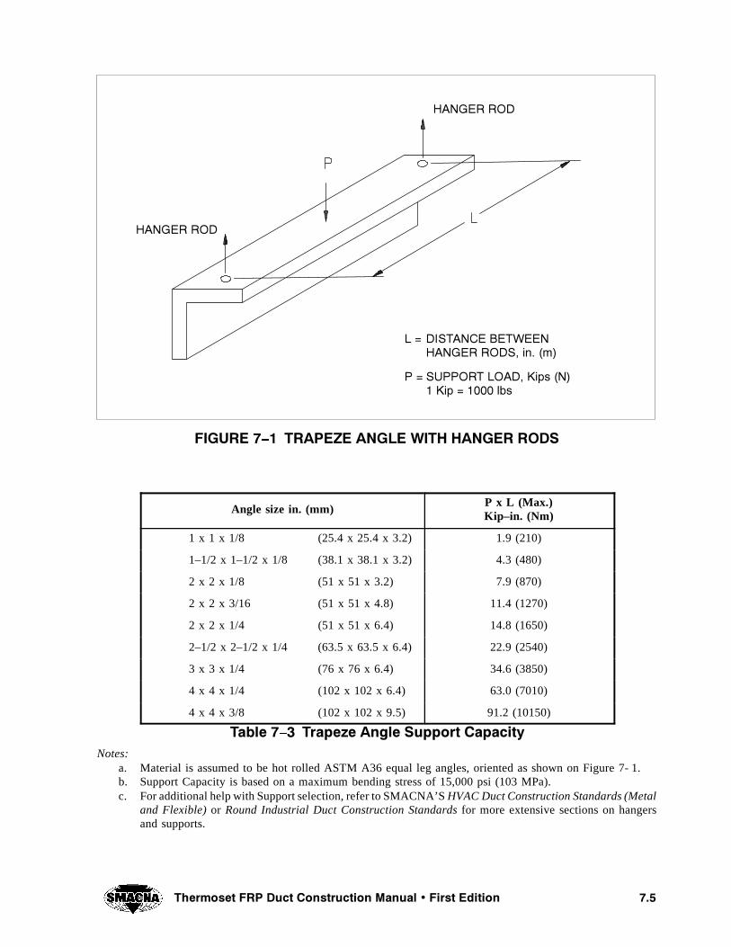
���4HERMOSET &20 $UCT #ONSTRUCTION -ANUAL � &IRST %DITION
&)'52% � � 42!0%:% !.',% 7)4( (!.'%2 2/$3
(!.'%2 2/$
(!.'%2 2/$
, � $)34!.#% "%47%%.(!.'%2 2/$3� IN� �M
0 � 3500/24 ,/!$� +IPS �.� +IP � ���� LBS
Angle size in. (mm)P x L (Max.)Kip–in. (Nm)
1 x 1 x 1/8 (25.4 x 25.4 x 3.2) 1.9 (210)
1–1/2 x 1–1/2 x 1/8 (38.1 x 38.1 x 3.2) 4.3 (480)
2 x 2 x 1/8 (51 x 51 x 3.2) 7.9 (870)
2 x 2 x 3/16 (51 x 51 x 4.8) 11.4 (1270)
2 x 2 x 1/4 (51 x 51 x 6.4) 14.8 (1650)
2–1/2 x 2–1/2 x 1/4 (63.5 x 63.5 x 6.4) 22.9 (2540)
3 x 3 x 1/4 (76 x 76 x 6.4) 34.6 (3850)
4 x 4 x 1/4 (102 x 102 x 6.4) 63.0 (7010)
4 x 4 x 3/8 (102 x 102 x 9.5) 91.2 (10150)
4ABLE � � 4RAPEZE !NGLE 3UPPORT #APACITYNotes:
a. Material is assumed to be hot rolled ASTM A36 equal leg angles, oriented as shown on Figure 7- 1.b. Support Capacity is based on a maximum bending stress of 15,000 psi (103 MPa).c. For additional help with Support selection, refer to SMACNA’SHVAC Duct Construction Standards (Metal
and Flexible) or Round Industrial Duct Construction Standards for more extensive sections on hangersand supports.

��� 4HERMOSET &20 $UCT #ONSTRUCTION -ANUAL � &IRST %DITION
Rod Diameterin. (mm)
Maximum Allowable Loadlb (kN)
1/4 (6.4) 240 (1.07)
5/16 (7.9) 380 (1.69)
3/8 (9.6) 610 (2.71)
1/2 (12.7) 1330 (5.03)
5/8 (15.8) 1810 (8.05)
3/4 (19.0) 2710 (12.05)
4ABLE � � (ANGER 2OD �!42 #APACITY
Notes:a. Above ratings are based on ATR (All Threaded Rod) made from ASTM A36, A575 GR1020, or A576 GR
1020.b. Ratings are consistent with SP–58, 1993 Editionby Manufacturers Standardization Society of the Valve
and Fittings Industry, Inc.c. Ratings are based on an allowable tensile stress of 9000 psi (62 MPa) calculated on the root cross–sectional
area of the thread.d. To rate threaded materials other than those listed in a. (above) refer toSP–58, 1993 Edition.
���� &5-% (//$3
Fume hoods are designed to capture and remove haz-ardous fumes from a specific work area. Hoodsmanufactured from FRP laminates generally followthe same guidelines as their metal counterparts. Cap-ture velocity, contaminate removal, and flow rate fol-low the same design principles as other hoods.
Two types of hoods commonly fabricated from FRPare: a) enclosing, and b) canopy designs. Enclosinghoods are partially or completely enclosed and relyon slot velocity to capture and remove the contamina-tes. They can be a) a back–draft design used for opentanks, b) fully enclosed laboratory hoods, c) fingerhoods for large vessels or d) push–pull designs wherelarge surface areas need to be exhausted. Canopyhoods are used overhead for large open vessels andrely on a combination of thermal vaporization and theexhaust flow rate to remove the contaminates. Thetype of hood needed is determined by its exact use andthe emissions that are to be removed from the area.The industrial process, access to the vessel and ap-propriate personnel safety will dictate the fume hoodbest suited for the application.
Hood flow rates and capture velocities necessary tomeet industrial ventilation requirements vary withtemperature, surface area, toxicity level and vaporparticle size. This specific information, as related to
corrosive contaminates, can be found in industry de-sign guidelines such as the one published by “TheAmerican Conference of Governmental IndustrialHygienists.”
Keeping hoods away from external air influences al-lows for the most efficient system. Exterior doors, airconditioning inlets and outlets, or equipment move-ment in close proximity to the hoods can cause a welldesigned system to exhaust poorly. Locate hoods inan area with the least amount of external air distur-bances. (See Appendix E, Referenced Documents.)
���� $!-0%23
������ 6OLUME $AMPERS
Volume dampers shall be installed at the locationsspecified by the project drawings for balancing andadjustment of the system. Acceptable damperconstruction techniques are illustrated in Figures7- 31 and 7- 32. Construction shall be such as to elim-inate dripping of condensate from duct penetrations.Volume dampers shall be provided with suitable cor-rosion–proof attachments for permanently settingdampers in a fixed position after balancing. Figure7- 32 illustrates a method of locking the damper bladein place, fabricators’ alternate designs may also beconsidered.

���4HERMOSET &20 $UCT #ONSTRUCTION -ANUAL � &IRST %DITION
������ "ACKâDRAFT $AMPERS
Back- draft dampers shall be provided where indi-cated on the drawings. Figure 7- 33 illustrates an ac-ceptable method of constructing a back–draft damperfrom FRP materials.
������ &IRE $AMPERS
Fire dampers shall be installed only where shown onthe project drawings. Life safety engineers stronglyrecommend that all systems conveying hazardousfumes be routed directly to the outside without pass-ing through fire partitions, so as to avoid using firedampers due to the possibility of inadvertent closingof the fire damper. Where the fire protection methodsspecified include the use of fire dampers; the location,type, and complete construction requirements of allfire dampers shall be set forth in the project drawingsor specifications.
When fire dampers are installed, a gasketed accesspanel shall be provided in the duct adjacent to eachdamper. Operating devices for the fire dampersshould be suitably protected from corrosive environ-ments.
���� !##%33 /0%.).'3 !.$ %.$ #!03
Access openings shall be provided in the duct workat the locations specified by the project drawings. Allaccess openings shall be rigidly framed and fittedwith air–tight covers which can be simply and speedi-ly removed and installed. Cover plate and end capthickness shall be a minimum of 1/4 in. (6 mm), andshall be reinforced across the shortest dimension asnecessary, to comply with the maximum spacing andrigidity requirements with widths equal to the shortestcover plate dimension. (See Figure 7- 34.) Attachinghardware should be spaced not more than 5 in. (125mm) center to center. Figure 7- 34 also illustrates ac-ceptable access door and capped duct construction.
���� $2!).3
Drains shall be installed at the locations indicated onthe project drawings. The drains shall be full–sized,FRP threaded half couplings, not less than 1 in. (25mm) IPS and suitable for receiving standard pipe con-nections unless otherwise specified. The fittings shallbe trimmed flush with the interior surface of the duct.Reinforcement bosses shall be provided in the FRPductwork wherever necessary to insure rigid connec-tion of drains.
���� 6%.4),!4/2 (%!$3 !.$ ,/56%23
Ventilator heads and louvers shall be installed whereindicated on the design drawings. Figures 7- 27 and7- 35 illustrate acceptable construction techniques forthese items.
���� &,%8)",% #/..%#4)/.3
Flexible connections shall be provided to handle ex-pansion and contraction in long runs of FRP duct, oras anti–vibration barriers at locations indicated on theproject drawings.
���� &,%8)",% -!4%2)!,3
Usually, an elastomeric sheet material, chosen to pro-vide corrosion resistance and temperature compatibil-ity suitable for the environment, is used to form theflexible coupling joint.
���� ,).%!2 #/%&&)#)%.4 /& 4(%2-!,%80!.3)/.
This coefficient is a function of the type of resin, thefillers used and the percentage of chopped glass, wo-ven roving or filament wound strands of reinforce-ment used. Usually, for chopped or hand layed upconstruction, assuming 30% glass content, the coeffi-cient of thermal expansion varies from a low of 10–5
in./in./^F (1.8 x 10⁻² mm/m/^C), to a high of 2.2 x10⁻⁵ in./in./^F (4.0 x 10⁻²mm/m/^C). If a single val-ue is required use 1.6 x 10⁻⁵ in./in./^F (2.9 x 10⁻²
mm/m/^C) (roughly twice that of steel and half thatof thermoplastic materials).
Note: The need for expansion joints is dependent onconditions and, in many cases, the configuration ofthe ductwork will be such that its thermal movementcan be accommodated without the use of such joints.When considering the thermal movement of ducts, theeffect on minor branches, thermocouple points, etc.,should be considered. These branches should be free-ly supported to assure that the movement of the mainduct is not opposed. Where this is not possible, flex-ible connections must be arranged between thebranches and the main duct. Design drawings shouldindicate the location for expansion joints when re-quired. Expansion joints may be in the form of modi-fied sleeve joints or bellows. Where possible, bellowsshould be located only in vertical legs to allow freedrainage. Location of drainage points should be indi-cated on the drawings. Drainage should be providedat low points of the system and where accumulationof moisture is anticipated.

��� 4HERMOSET &20 $UCT #ONSTRUCTION -ANUAL � &IRST %DITION
���� 4/,%2!.#%3
The definitions used in this manual are in accordancewith industry standards and as shown in ASTMD–883.
������ /UT OF 2OUNDNESS
For ducts 6 in. (150 mm) or less in diameter, the toler-ance is ± 1/16 in. (1.6 mm). For ducts larger than 6in. (150 mm) in diameter, the tolerance is ± 1/8 in.(3.2 mm) or ± 1% of the diameter, whichever is great-er. In no event shall the tolerance be more than 3/4in. (19.1 mm).
������ /VERALL ,ENGTH
The overall section length shall be the specifiedlength ± 1/4 in. (6.4 mm).
������ 3QUARENESS
The cut end of round duct shall be square within:
± 1/8 in. (3.2 mm) for duct up to 24 in. (610 mm)in diameter,
± 3/16 in. (48 mm) for duct 24 in. (610 mm) upto 48 in. (1220 mm) in diameter, and
± 1/4 in. (6.4 mm) for duct larger than 48 in.(1220 mm) in diameter.
Note: Using the longest side of a rectangular duct findthe next larger standard round duct diameter and usethat diameter to determine the tolerance for the entireduct section.
������ &LANGED OR 0LAIN %ND $UCT AND &IT TINGS
Flanged or plain end duct and fittings must be withinthe following angles from their design location:
For duct 24 in. (610 mm) and less in diameter,the tolerance is ± 1̂
For duct larger than 24 in. (610 mm) and up to48 in. (1220 mm) in diameter, the tolerance is ± 3/4^
For duct larger than 48 in. (1220 mm) in diame-ter, the tolerance is ± 1/2̂
������ &LANGE 4OLERANCE
a. Warpage = ± 3̂
b. Offset = ± 1/8 in. (3.2 mm) 1/2̂
c. Perpendicularity = ± 1/2̂
d. Cant = ± 1/2̂
e. Flange flatness = ± 1/32 in. (0.8 mm) forducts under 18 in. (460 mm) in diameter and± 1/16 in. 91.6 mm) for ducts larger than 18in. (460 mm).
f. Back of Flange face: Back of Flange faceshall be parallel with the flange face within± 1^, otherwise spot face back of flange foracceptable washer seating.
���� $2!).!'%
FRP duct systems must be installed allowing fordrainage of condensate. Sloping horizontal runs andthe provision for deep seal traps allow collection, anddisposal of the condensate. Special handling and dis-posal of contaminated fluids may be required to meetEPA regulations.
���� 302).+,%23
When sprinklers are required, the duct system shallbe installed with access doors, or other means to per-mit easy handling and installation of the sprinklerheads. When sprinkler systems are installed, a drain-age system must be engineered to properly drain theduct system.
���� "52)%$ $5#4
All buried ducts destined to operate under direct con-tact with back–fill materials require special structuraldesign to handle the unique loads typical of suchinstallations.
FRP ducts designed per the requirements of thismanual DO NOT include consideration of the specialstructural requirements of buried duct.
���� -!.5&!#452%2è3 3(/0 2%6)%7
It is recommended that the end user should visit andinspect a fabricator’s facilities and review his require-ments before issuing a contract to build and installFRP duct. Evidence of past performance can relieveproblems and enhance the relationship between par-ties.
���� ).30%#4)/.
The FRP duct fabricator shall cooperate with theOwners inspector in the following manner:
���4HERMOSET &20 $UCT #ONSTRUCTION -ANUAL � &IRST %DITION
a. Make available to the inspector such recordspertaining to the fabrication of FRP ductingas required to permit the inspector to per-form his duties. These shall include draw-ings, design calculations, material test re-sults, physical test data, materials supplier’sproduct certifications, and any other reportsor records pertaining to the job in process.
b. The fabricator shall make his quality controlpersonnel available to the inspector.
c. The fabricator shall make available any nec-essary tools and test equipment for the in-spector to conduct his inspections as re-quired to meet this standard.
d. The fabricator shall make available to the in-spector any cut–out specimens of laminatesleft over from the job.
e. The finished FRP duct laminate shall not betacky to touch when conducting an acetonetest for resin cure. (Apply a small drop ofacetone to the laminate surface, rub cleanwith a dry cheese cloth, check for evidenceof resin residue on the cloth.)
f. Barcol hardness shall be in accordance withASTM D2583 and the quality control sectionof Chapter 8. (See Chapter 8 – Quality Con-trol and Safety, for details on surface hard-ness requirements, testing and other qualitycontrol topics.)
g. Visual appearance – The finished laminateshall generally conform to the visual accep-tance criteria of Table 5, ASTM C582. Crite-ria include no cracks, pits, crazing, blisters,wrinkles, dry spots (unwetted glass fiber),chips and gouges, entrapped air, or foreignmatter in the laminate substrate.
���� (!.$,).'� 3()00).'� !.$ ).34!, ,!4)/.
������ (ANDLING
FRP duct laminates require special attention in han-dling. While the material provides excellent self sup-porting strength when properly installed, it is suscep-tible to cracking and crazing if impacted by sharpobjects. (Review ASTM D3982 for additional detailson shipping, handling, and installation.)
������ 3HIPPING
Because of the light weight of fiberglass duct andhoods, the primary determinants of the overall dimen-sions of the subassemblies will be the dimensionalshipping limitations. The dimensions of the subas-semblies shall be determined by the manufacturer andthe purchaser.
The following list includes typical precautions thatcan prevent or reduce the incidence of damage duringloading, transit, and unloading:
a. Protect all ductwork for shipment, and espe-cially appurtenances, that could be easilydamaged.
b. Protect all flange surfaces with woodenblinds or other approved material.
c. Support large subassemblies during ship-ment and unloading to prevent excessivedeflection and over stressing.
d. Unload the equipment with care and store itin a location where it will be free of damage.Impact of a tool or other heavy object mayresult in a fracture of the inner lining andmay affect the service life of the system.
������ )NSTALLATION
The following list describes minimum requirementsfor the proper installation of FRP duct systems:
a. Use properly designed hangers with a mini-mum of 150̂ circumferential contact (forround duct) and 2 in. (51 mm) minimum lon-gitudinal contact. All ducts included in thismanual are designed for a maximum supportspacing of 10 ft (3050 mm).
b. All other equipment or service loads shall besupported independently.
c. Use flexible connections to isolate ductworkfrom vibration caused by air–moving equip-ment.
d. Use full–face gaskets to eliminate any canti-lever effect caused from bolting.
e. Tighten bolting on flanged connections fol-lowing torque values given in section 7.14.3.
f. Tighten bolts following the sequence shownin Figure 7- 7.
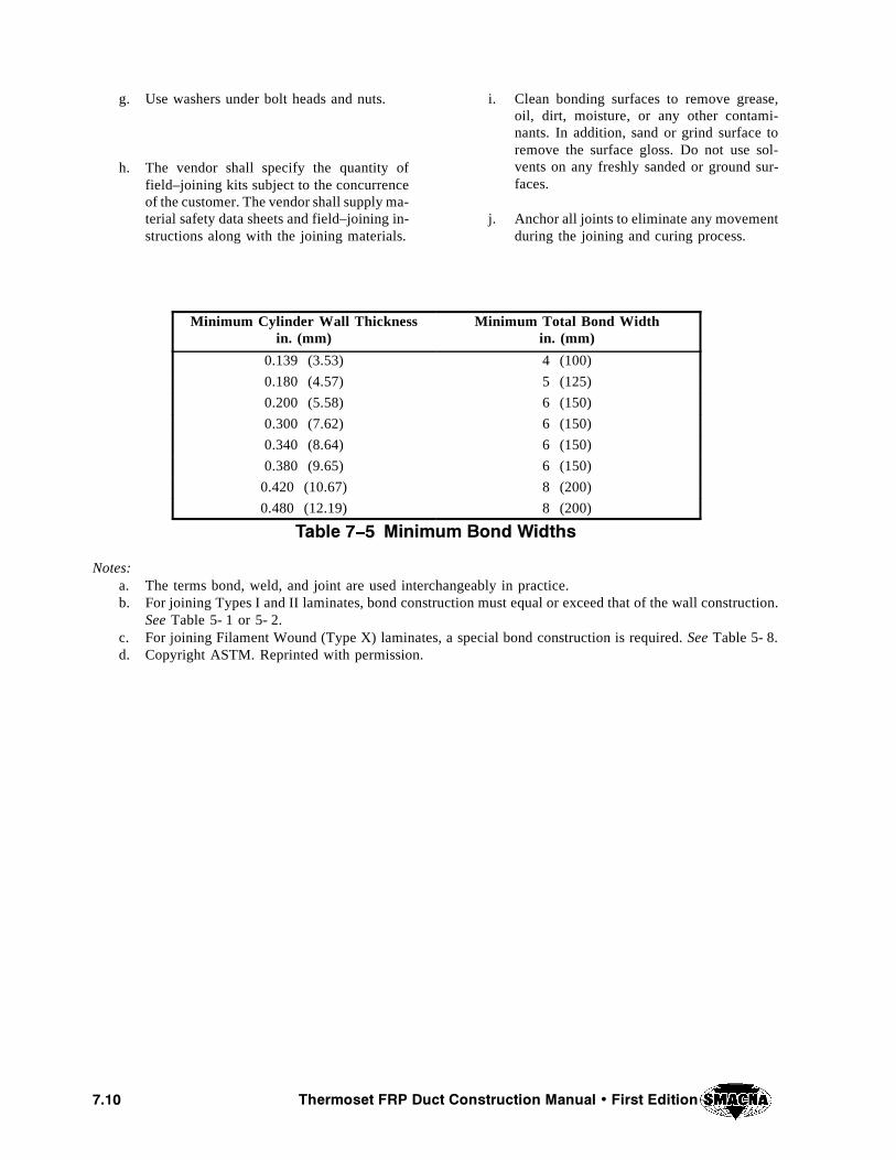
���� 4HERMOSET &20 $UCT #ONSTRUCTION -ANUAL � &IRST %DITION
g. Use washers under bolt heads and nuts.
h. The vendor shall specify the quantity offield–joining kits subject to the concurrenceof the customer. The vendor shall supply ma-terial safety data sheets and field–joining in-structions along with the joining materials.
i. Clean bonding surfaces to remove grease,oil, dirt, moisture, or any other contami-nants. In addition, sand or grind surface toremove the surface gloss. Do not use sol-vents on any freshly sanded or ground sur-faces.
j. Anchor all joints to eliminate any movementduring the joining and curing process.
Minimum Cylinder Wall Thicknessin. (mm)
Minimum Total Bond Widthin. (mm)
0.139 (3.53) 4 (100)
0.180 (4.57) 5 (125)
0.200 (5.58) 6 (150)
0.300 (7.62) 6 (150)
0.340 (8.64) 6 (150)
0.380 (9.65) 6 (150)
0.420 (10.67) 8 (200)
0.480 (12.19) 8 (200)
4ABLE � � -INIMUM "OND 7IDTHS
Notes:a. The terms bond, weld, and joint are used interchangeably in practice.b. For joining Types I and II laminates, bond construction must equal or exceed that of the wall construction.
See Table 5- 1 or 5- 2.c. For joining Filament Wound (Type X) laminates, a special bond construction is required.See Table 5- 8.d. Copyright ASTM. Reprinted with permission.

����4HERMOSET &20 $UCT #ONSTRUCTION -ANUAL � &IRST %DITION
&)'52% � � &,!.'% #!.4
#OPYRIGHT !34-�2EPRINTED WITH PERMISSION
&,!.'% #!.4
-!). 25. #%.4%2,).%"2!.#( #%.4%2,).%
&)'52% � � &,!.'% 4/,%2!.#% $%3#2)04)/.
#OPYRIGHT !34-�2EPRINTED WITH PERMISSION
7!3(%2 3%!,).'0!2!,,%, 7)4(&,!.'% &!#%
&,!.'%7!20!'%
0,!.% /&4(% )$
&,!.'%0%20%.$)#5,!2
&,!.'%&,!4.%33
0,!.% 0%20%.$)#5,!2 4/$5#4è3 #%.4%2,).%

���� 7KHUPRVHW )53 'XFW &RQVWUXFWLRQ 0DQXDO � )LUVW (GLWLRQ
),*85( �ï� )/$1*( 2))6(7
Copyright ASTM.Reprinted with permission
FLANGE OFFSET
MAIN RUN CENTERLINEBRANCH CENTERLINE
),*85( �ï� )/$1*( $77$&+0(17
Copyright ASTM.Reprinted with permission
CORROSIONBARRIER
CORROSIONBARRIER
CORROSIONBARRIER
CORROSIONBARRIER
�$� ´)/$1*(21 '8&7µ 7<3( �%� ´,17(*5$/µ 7<3(
3/8" (9.5 mm)RADIUSMINIMUM
3/8" (9.5 mm)RADIUSMINIMUM
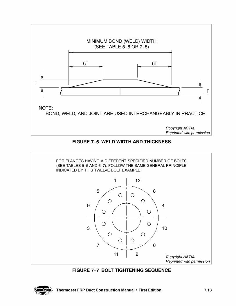
����4HERMOSET &20 $UCT #ONSTRUCTION -ANUAL � &IRST %DITION
&)'52% � � 7%,$ 7)$4( !.$ 4()#+.%33
#OPYRIGHT !34-�2EPRINTED WITH PERMISSION
-).)-5- "/.$ �7%,$ 7)$4(�3%% 4!",% � � /2 � �
./4%�"/.$� 7%,$� !.$ */).4 !2% 53%$ ).4%2#(!.'%!",9 ). 02!#4)#%
&)'52% � � "/,4 4)'(4%.).' 3%15%.#%
&/2 &,!.'%3 (!6).' ! $)&&%2%.4 30%#)&)%$ .5-"%2 /& "/,43�3%% 4!",%3 � � !.$ � �� &/,,/7 4(% 3!-% '%.%2!, 02).#)0,%).$)#!4%$ "9 4()3 47%,6% "/,4 %8!-0,%�
#OPYRIGHT !34-�2EPRINTED WITH PERMISSION
�
�
��
��
�
�
�
�
�
� ��
�

���� 7KHUPRVHW )53 'XFW &RQVWUXFWLRQ 0DQXDO � )LUVW (GLWLRQ
),*85( �ï� 648$5( 7+52$7 (/%2:6
STRAIGHT IN
STRAIGHT OUT
WIDTH OUTx
DEPTH OUT
),*85( �ï� 5281' 25 5(&7$1*8/$5 67$1'$5' (/%2:
CENTERRADIUS

����7KHUPRVHW )53 'XFW &RQVWUXFWLRQ 0DQXDO � )LUVW (GLWLRQ
),*85( �� 5281' 25 5(&7$1*8/$5 $1*/(6
CENTERRADIUS
WIDTH (W)x
DEPTH (DR)
ROUND D
RECTANGULAR CENTER RADIUSR = 1.5W (min.)ROUND CENTER RADIUSR = 1.5D (min.)
),*85( �� 5(&7$1*8/$5 7((6
LT.STRAIGHT
OUT RT.STRAIGHT
OUT
LT.WIDTH OUT
RT.WIDTH OUT
LT.STRAIGHT IN

���� 7KHUPRVHW )53 'XFW &RQVWUXFWLRQ 0DQXDO � )LUVW (GLWLRQ
),*85( �� 5281' 25 5(&7$1*8/$5 2))6(76
STRAIGHT IN
STRAIGHT OUT
LENGTH
RIGHT SETLEFT SET
),*85( �� 75$16,7,21 (/%2:6
CENTERRADIUS
WIDTH OUTx
DEPTH OUT
ANGLE

����7KHUPRVHW )53 'XFW &RQVWUXFWLRQ 0DQXDO � )LUVW (GLWLRQ
),*85( �� ),9( 6(*0(17 (/%2:
STRAIGHT IN
STRAIGHT OUT
CENTER RADIUSR = 1.5D
),*85( �� 5281' � 648$5( 5('8&(56
STRAIGHT IN
STRAIGHT OUT
LENGTH
RIGHT SETLEFT SET
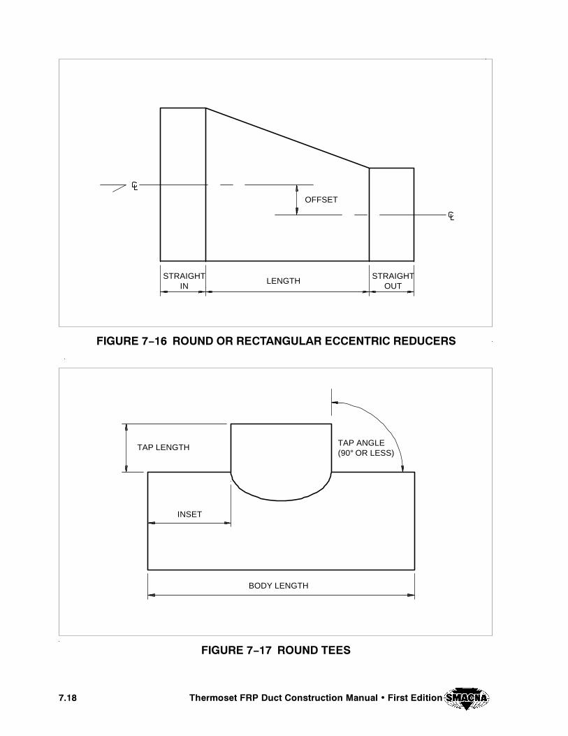
���� 7KHUPRVHW )53 'XFW &RQVWUXFWLRQ 0DQXDO � )LUVW (GLWLRQ
),*85( �� 5281' 25 5(&7$1*8/$5 (&&(175,& 5('8&(56
STRAIGHTIN
STRAIGHTOUT
LENGTH
OFFSET
),*85( �� 5281' 7((6
TAP LENGTH TAP ANGLE(90° OR LESS)
BODY LENGTH
INSET
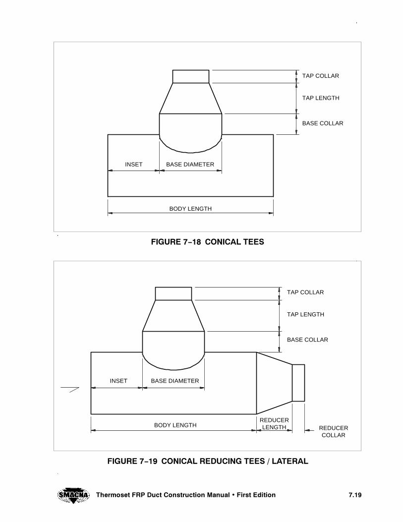
����7KHUPRVHW )53 'XFW &RQVWUXFWLRQ 0DQXDO � )LUVW (GLWLRQ
),*85( �� &21,&$/ 7((6
TAP LENGTH
TAP COLLAR
BASE COLLAR
BASE DIAMETER
BODY LENGTH
INSET
),*85( �� &21,&$/ 5('8&,1* 7((6 � /$7(5$/
TAP LENGTH
TAP COLLAR
BASE COLLAR
BASE DIAMETER
BODY LENGTH
INSET
REDUCERLENGTH REDUCER
COLLAR

���� 7KHUPRVHW )53 'XFW &RQVWUXFWLRQ 0DQXDO � )LUVW (GLWLRQ
),*85( �� 5('8&,1* 7((6 � /$7(5$/
TAP LENGTH
INSET
REDUCERLENGTH REDUCER
COLLAR
BODY LENGTH
TAP ANGLE
),*85( �� &21,&$/ /$7(5$/6
TAP ANGLE(90° OR LESS)
TAP LENGTH
TAP COLLAR
BASE COLLAR
BASEDIAMETER
BODY LENGTH
INSET
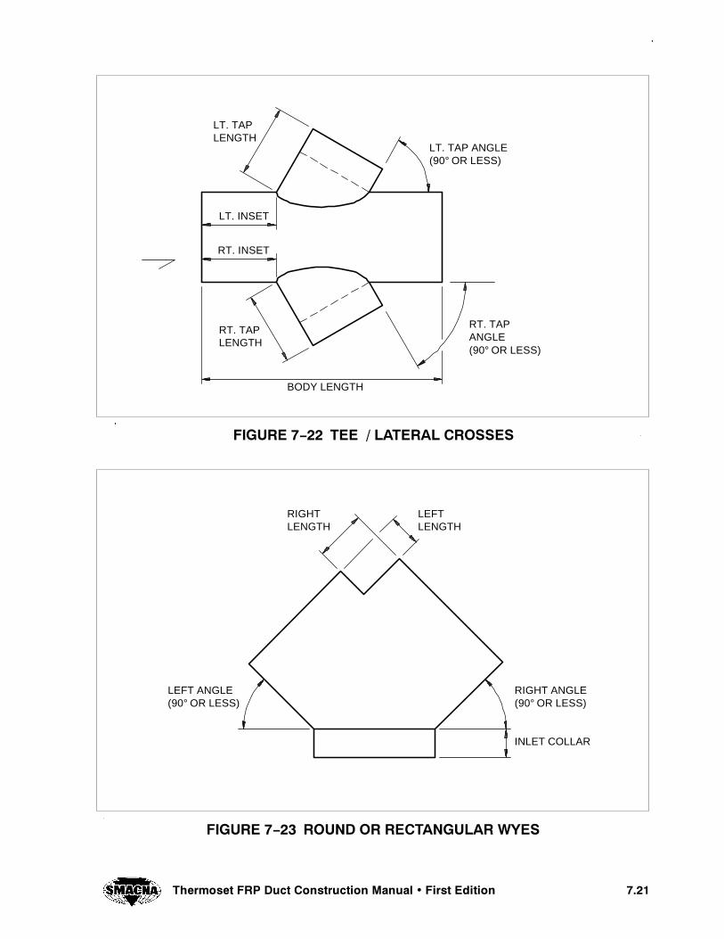
����7KHUPRVHW )53 'XFW &RQVWUXFWLRQ 0DQXDO � )LUVW (GLWLRQ
),*85( �� 7(( � /$7(5$/ &5266(6
LT. TAP ANGLE(90° OR LESS)
RT. TAPANGLE(90° OR LESS)
RT. INSET
LT. INSET
RT. TAPLENGTH
LT. TAPLENGTH
BODY LENGTH
),*85( �� 5281' 25 5(&7$1*8/$5 :<(6
LEFT ANGLE(90° OR LESS)
RIGHT ANGLE(90° OR LESS)
RIGHTLENGTH
LEFTLENGTH
INLET COLLAR

���� 7KHUPRVHW )53 'XFW &RQVWUXFWLRQ 0DQXDO � )LUVW (GLWLRQ
),*85( �� 5281' 25 5(&7$1*8/$5 5('8&,1* :<(6
RT. TAPLENGTH
RT. COLLAR
LT. BASEDIAMETER
RT. BASEDIAMETER
LT. TAPLENGTH
LT. LENGTH
RT.LENGTH
LT. COLLAR
INLET COLLAR
),*85( �� 5281' 25 5(&7$1*8/$5 2))6(76
STRAIGHTIN
STRAIGHTOUTLENGTH
RISE
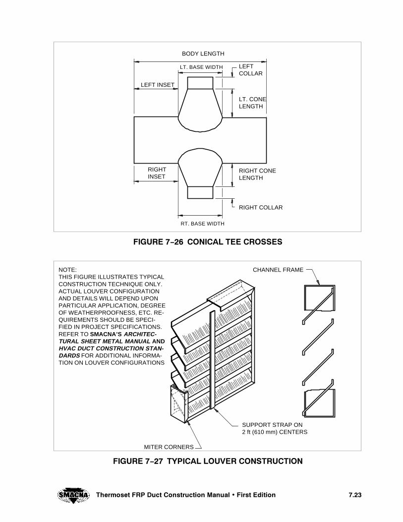
����7KHUPRVHW )53 'XFW &RQVWUXFWLRQ 0DQXDO � )LUVW (GLWLRQ
),*85( �� &21,&$/ 7(( &5266(6
RIGHT COLLAR
BODY LENGTH
LEFTCOLLAR
LT. CONELENGTH
RIGHT CONELENGTH
RIGHTINSET
RT. BASE WIDTH
LT. BASE WIDTH
LEFT INSET
),*85( �� 7<3,&$/ /289(5 &216758&7,21
NOTE:THIS FIGURE ILLUSTRATES TYPICALCONSTRUCTION TECHNIQUE ONLY.ACTUAL LOUVER CONFIGURATIONAND DETAILS WILL DEPEND UPONPARTICULAR APPLICATION, DEGREEOF WEATHERPROOFNESS, ETC. RE-QUIREMENTS SHOULD BE SPECI-FIED IN PROJECT SPECIFICATIONS.REFER TO SMACNA’S ARCHITEC-TURAL SHEET METAL MANUAL ANDHVAC DUCT CONSTRUCTION STAN-DARDS FOR ADDITIONAL INFORMA-TION ON LOUVER CONFIGURATIONS
MITER CORNERS
SUPPORT STRAP ON2 ft (610 mm) CENTERS
CHANNEL FRAME

���� 4HERMOSET &20 $UCT #ONSTRUCTION -ANUAL � &IRST %DITION
&)'52% � �� $5#4 (!.'%23 â (/2):/.4!,
(!.'%2 2/$3
4(2%!$%$2/$
&,!4 "!2
&,!4 "!230,)4 2).'
!.',% )2/. .5434/0 � "/44/-
53% 3).',% (!.'%2 &/2$5#43 ��ì ���� MM !.$ "%,/7
./4%3��� 3%% 4!",%3 � � 4(2/5'( � � &/2 (!.'%2 2%15)2%-%.43�� 3500/243 3(/7. $/ ./4 ).#,5$% 3%)3-)# #/.3)$%2!4)/.3�� !00,)#!4)/.3 7()#( ).6/,6% 2%0%4)4)6% !8)!, -/6%-%.43 /& 4(% $5#4
!3 ! 2%35,4 /& %80!.3)/.� #/.42!#4)/.� /2 6)"2!4)/. -!9 2%15)2% 4(%!$$)4)/./&7%!20,!4%3 "%47%%. 4(%$5#4 !.$ )43 (!.'%23 !.$3500/243

����7KHUPRVHW )53 'XFW &RQVWUXFWLRQ 0DQXDO � )LUVW (GLWLRQ
),*85( �� 6833257 )25 9(57,&$/ '8&7
SUPPORT
EXPANSIONJOINT WHERECONDITIONSNECESSITATE (ASSPECIFIED IN THEDESIGNDOCUMENTATIONONLY)
GUIDE (SAME ASSUPPORT WITHOUTGIRTH STRAP)
RECTANGULARDUCT
FRP STRAPSECURED TODUCT WITHRESIN
ANGLESBOLTEDTO STEELBRACKET
STEELBRACKETBOTHSIDES
ROUNDDUCT
FRP GIRTHSTRAP SECUREDTO DUCT WITHRESIN
STEEL SPLIT RING,CLOSE FIT (NOTCOMPRESSED)SUPPORT
STEEL CLIPWELDED TOBRACKET
STEEL BRACKETBOTH SIDES
SUPPORT
NOTE:SUPPORTS SHOWN DO NOT INCLUDE SEISMIC CONSIDERATIONS
MA
X.D
IST
AN
CE
BE
TW
EE
NS
UP
PO
RT
S=
16ft
(4.9
m)
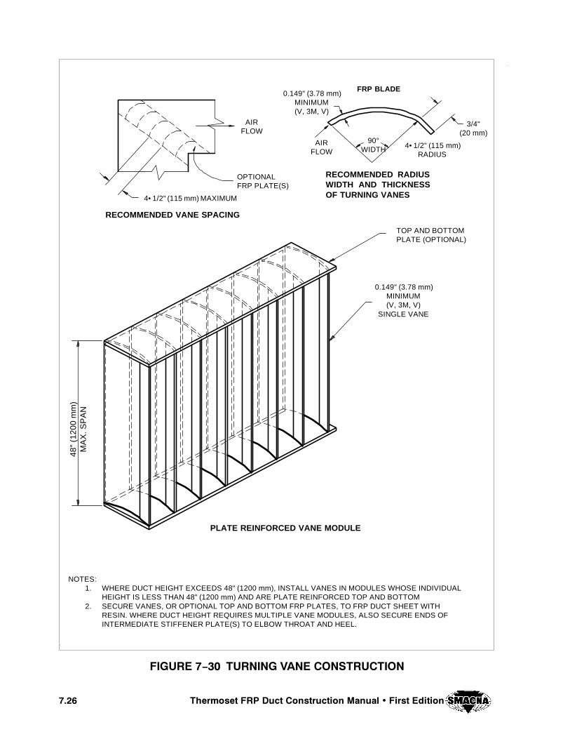
���� 7KHUPRVHW )53 'XFW &RQVWUXFWLRQ 0DQXDO � )LUVW (GLWLRQ
),*85( �� 7851,1* 9$1( &216758&7,21
RECOMMENDED VANE SPACING
RECOMMENDED RADIUSWIDTH AND THICKNESSOF TURNING VANES
FRP BLADE
4• 1/2" (115 mm) MAXIMUM
AIRFLOW
OPTIONALFRP PLATE(S)
AIRFLOW
90°WIDTH 4• 1/2" (115 mm)
RADIUS
3/4"(20 mm)
0.149" (3.78 mm)MINIMUM(V, 3M, V)
0.149" (3.78 mm)MINIMUM(V, 3M, V)
SINGLE VANE
TOP AND BOTTOMPLATE (OPTIONAL)
PLATE REINFORCED VANE MODULE
NOTES:1. WHERE DUCT HEIGHT EXCEEDS 48" (1200 mm), INSTALL VANES IN MODULES WHOSE INDIVIDUAL
HEIGHT IS LESS THAN 48" (1200 mm) AND ARE PLATE REINFORCED TOP AND BOTTOM2. SECURE VANES, OR OPTIONAL TOP AND BOTTOM FRP PLATES, TO FRP DUCT SHEET WITH
RESIN. WHERE DUCT HEIGHT REQUIRES MULTIPLE VANE MODULES, ALSO SECURE ENDS OFINTERMEDIATE STIFFENER PLATE(S) TO ELBOW THROAT AND HEEL.
48"
(120
0m
m)
MA
X.S
PA
N
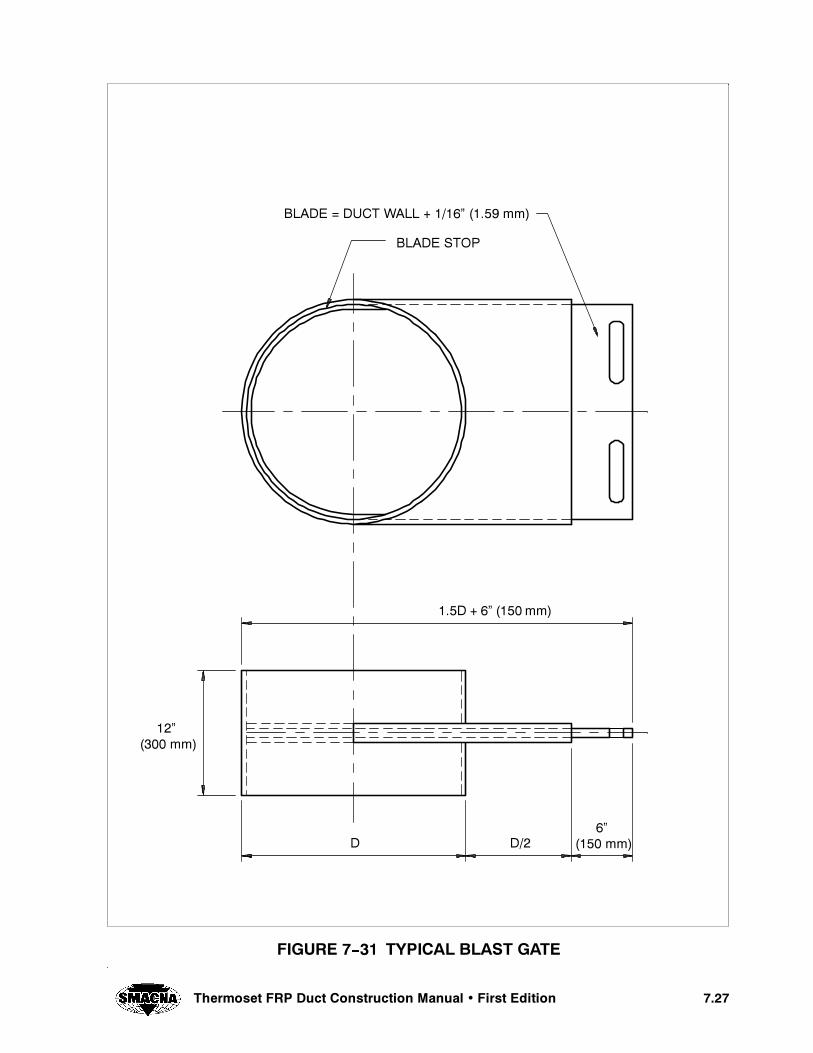
����4HERMOSET &20 $UCT #ONSTRUCTION -ANUAL � &IRST %DITION
&)'52% � �� 490)#!, ",!34 '!4%
",!$% � $5#4 7!,, � ����ì ����� MM
",!$% 34/0
���$ � �ì ���� MM
����� MM
���� MM$��$
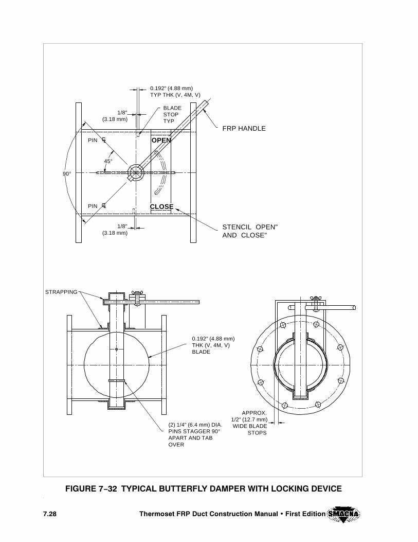
���� 7KHUPRVHW )53 'XFW &RQVWUXFWLRQ 0DQXDO � )LUVW (GLWLRQ
),*85( �� 7<3,&$/ %877(5)/< '$03(5 :,7+ /2&.,1* '(9,&(
FRP HANDLE
STENCIL OPEN"AND CLOSE"
BLADESTOPTYP
1/8"(3.18 mm)
0.192" (4.88 mm)TYP THK (V, 4M, V)
PIN
PIN
45°
90°
1/8"(3.18 mm)
OPEN
CLOSE
0.192" (4.88 mm)THK (V, 4M, V)BLADE
STRAPPING
(2) 1/4" (6.4 mm) DIA.PINS STAGGER 90°APART AND TABOVER
APPROX.1/2" (12.7 mm)WIDE BLADE
STOPS

����7KHUPRVHW )53 'XFW &RQVWUXFWLRQ 0DQXDO � )LUVW (GLWLRQ
),*85( �ï�� *5$9,7< %$&.²'5$)7 '$03(5 )25 9(57,&$/ '8&7
45°45°
BOLT HOLESSTRADDLE
1/2" (12.7 mm) DIA.6 HOLES
1/2" (12.7 mm) DIA.2 HOLES 180° APART
1-1/2" (38.1 mm)
ROD W/ TUBE
0.125" (3.18 mm)MIN. FRP BLADES
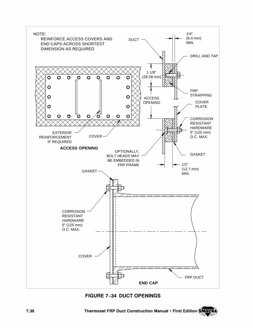
���� 7KHUPRVHW )53 'XFW &RQVWUXFWLRQ 0DQXDO � )LUVW (GLWLRQ
),*85( �� '8&7 23(1,1*6
NOTE:REINFORCE ACCESS COVERS ANDEND CAPS ACROSS SHORTESTDIMENSION AS REQUIRED
DUCT
1/4"(6.4 mm)MIN.
DRILL AND TAP
1-1/8"(28.58 mm)
ACCESSOPENING
FRPSTRAPPING
COVERPLATE
CORROSIONRESISTANTHARDWARE5" (125 mm)O.C. MAX.
EXTERIORREINFORCEMENT
IF REQUIRED
COVER
GASKETOPTIONALLY,
BOLT HEADS MAYBE EMBEDDED IN
FRP FRAME
GASKET
1/2"(12.7 mm)MIN.
CORROSIONRESISTANTHARDWARE5" (125 mm)O.C. MAX.
COVER
ACCESS OPENING
FRP DUCT
END CAP
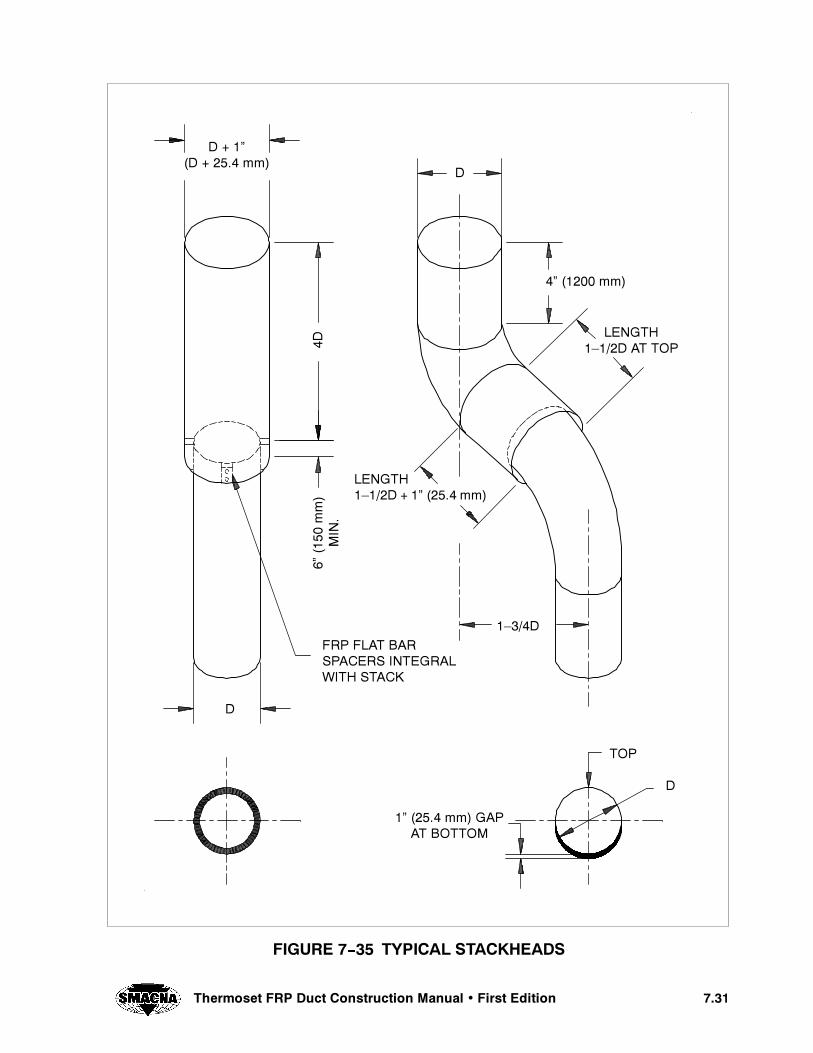
����4HERMOSET &20 $UCT #ONSTRUCTION -ANUAL � &IRST %DITION
&)'52% � �� 490)#!, 34!#+(%!$3
$ � �ì�$ � ���� MM
�$
,%.'4(�â���$ � �ì ����� MM
,%.'4(���$ !4 4/0
�ì ����� MM
���$
����
MM
-).
�
&20 &,!4 "!230!#%23 ).4%'2!,7)4( 34!#+
4/0
�ì ����� MM '!0!4 "/44/-
$
$
$

���� 4HERMOSET &20 $UCT #ONSTRUCTION -ANUAL � &IRST %DITION
4()3 0!'% ).4%.4)/.!,,9 ,%&4 ",!.+

CHAPTER 8
QUALITY CONTROL ANDSAFETY
15!,)49 #/.42/, !.$ 3!&%49#(!04%2 �
���4HERMOSET &20 $UCT #ONSTRUCTION -ANUAL � &IRST %DITION
��� 15!,)49 #/.42/,
����� 'ENERAL
The fabricator shall have a quality control program,to ensure that all the requirements of the ThermosetFRP Duct Construction Manual are met, as agreed tobetween the fabricator and the user.
The fabricator shall maintain a quality control pro-gram suitable for the scope of the work to be per-formed.
A copy of the fabricator’s quality control manual shallbe made available to the user’s inspector on request,along with any quality control forms used duringconstruction of the FRP duct.
����� /RGANIZATION
The quality control program shall include the fabrica-tor’s organizational chart, which indicates reportingresponsibility and authority. This chart should illus-trate that the quality control function is independentof the production group.
����� $OCUMENTATION
The quality control program shall include the docu-mentation required by this manual, organized in oneplace and made readily available to the user’s inspec-tor during fabrication.
The quality control program shall ensure that the lat-est applicable drawings, design calculations, specifi-cations, and any addenda to this manual are used inthe fabrication, inspection, and testing of the ductcomponents.
The quality control program must include specificprocedures for the following:
a. Inspection of received goods, including rawmaterials and purchased items, i.e., any ma-terials that will become part of the finishedFRP duct.
b. In–process inspection of resin mixing, rawmaterial dispersement, component fabrica-tion, and assembly procedures including ver-ification of reinforcement sequence.
c. Record all Barcol hardness and laminatethickness tests. The records shall be main-tained together with other quality controldata.
d. Rectification of any nonconformities or im-perfections to the FRP duct prior to final in-spection and approval for shipment. Such re-pairs shall be recorded and include the dateof correction and specific location of the re-pair on the duct laminate.
e. Scheduling and notification to the user’s in-spector for a final inspection and acceptanceof the FRP duct components.
����� "ARCOL (ARDNESS
Take a single Barcol reading near the 1/3 and 2/3lengths (longitudinal direction) of the duct and nearthe middle (transverse direction) of each of the sides,top, and bottom of rectangular duct (or approximatelyat 0, 90, 180, and 270 degree for round duct), resultingin a total of 8 readings. Remove the highest and low-est value and the average of the remaining valuesshould be equal to or greater than 90% of the Barcolhardness value established by the resin manufacturerfor the cured resin.
Exception: Laminate surfaces finished with syntheticveil and resin are considered adequately cured whenthe average hardness, established as describedabove, equals or exceeds 80% of the Barcol hardnessvalue established by the resin manufacturer for thecured resin.
Low Barcol values due to pits or other defects shouldbe eliminated and not included in the 8 readings. Thetests shall be performed on at least 10% of all the ductsections being manufactured. To check Barcol hard-ness of FRP components, refer to ASTM D2583.
Under–cured laminates exhibiting low Barcol read-ings should be post–cured at a minimum of 180^F(82̂ C) for sufficient time to increase Barcol hardnessin excess of the minimum Barcol hardness require-ments.
����� 4OLERANCE FOR !VERAGE 4HICKNESS
The acceptability of a duct’s wall thickness shall beevaluated on the basis of its average thickness, de-fined as the arithmetic average of six spot thicknessvalues taken at random. The duct’s average thicknessshall not be less than 85%, nor greater than 120%, ofthe design wall thickness (also referred to as requiredwall thickness). In determining the average thickness,the lowest of all readings taken shall not be less than(minimum thickness) 70%, nor greater than (maxi-mum thickness) 130%, of the design wall thickness.Isolated low spots may be repaired, at the option of
��� 4HERMOSET &20 $UCT #ONSTRUCTION -ANUAL � &IRST %DITION
the fabricator, so that upon re–testing of the repairedarea, the minimum spot thickness, as well as the aver-age spot thickness for the duct section meet the crite-ria stated above. If isolated spots or the duct’s averagethickness exceed the tolerance criteria on the plusside, acceptance of round duct is at the discretion ofthe parties involved, while acceptance of rectangularduct may require engineering analysis, since excessthickness (beyond the tolerance limit) in one area mayresult in overstressing other parts of the duct wall.
��� 3!&%49
����� -ATERIAL 3AFETY $ATA 3HEETS �-3$3
Material Safety Data Sheets (MSDS) are availablefrom all thermoset resin manufacturers. The MSDScontains health and safety information to assist han-dlers in developing appropriate product handling pro-cedures to protect the employees. The MSDS shouldbe read and understood by all personnel before han-dling the resins and other raw materials used for fabri-cating and installing FRP duct systems.
����� 3TYRENE
All thermoset resins are polymers diluted with styrenemonomer in order to obtain a workable viscosity. Thehazardous ingredient in the resins is styrene. Thepolymer itself is non–hazardous. Styrene has a pun-gent odor that is easily detected due to the low sensi-tivity of odor detection of 1 ppm. Finished FRPconstructed laminates will retain a residual styreneodor after curing for several days or even weeks. Sty-rene is subject to a number of federal regulations.Current styrene regulations should be reviewed priorto handling styrenated products.
����� &LAMMABILITY
Thermoset polyester and vinyl ester liquid resins areflammable due to the presence of styrene monomer.These resins should be stored away from heat sourcessuch as: space heaters, open flames, and spark pro-ducing equipment.SMOKING IS STRICTLY PRO-HIBITED.
In the event of a fire involving styrenated resins, itis recommended that the flames be extinguished byusing foam, dry powder or carbon dioxide. The useof water is not recommended because the resins areinsoluble in water, and may spread the fire as they arecarried along by the water current.
When these resins burn, toxic gases such as carbonmonoxide, and halogenated–products of combustionare produced. Caution should be used to avoid inhala-tion of these toxic fumes. A self–contained breathingapparatus should be worn when extinguishing suchfires.
��� (%!,4( #/.#%2.3
����� 3KIN #ONTACT
Protective gloves and clothing should be worn toavoid skin contact while handling styrenated resins.Prolonged or repeated skin contact may cause skin ir-ritation. Any contact with the skin should be washedthoroughly with soap and water. If irritation persists,seek medical attention or use a recommended skincream to soothe and seal the pores of the skin.
����� %YE #ONTACT
Chemical goggles shall be worn at all times whenworking with liquid resins, or grinding and sandingcured laminates. If exposure to these products causeseye irritation, stinging, redness, or swelling, flush theeyes with plenty of water.DO NOT RUB DRY. If thesymptoms persist, seek medical attention.
����� )NHALATION
Do not inhale styrenated resin vapors or dust fromgrinding. Provide adequate ventilation to minimizeinhalation. The personal exposure limit to styrene is50 PPM as an 8 hour time weighted average. Re-peated excessive exposures to high amounts maycause central nervous system, liver, kidney effectsand respiratory or eye irritation. Repeated exposuresto smaller amounts may cause central nervous systemeffects and respiratory or eye irritation. If inhalationsymptoms develop, move the person to fresh air im-mediately. If the person has difficulty in breathing,administer oxygen or provide artificial respiration,keep the person warm, and seek medical assistance.
����� )NGESTION
If accidentally swallowed, do not induce vomiting asthe resin material is an aspiration hazard. Seek medi-cal attention immediately. Do not leave the personunattended while help arrives.
����� #HRONIC (EALTH %FFECTS
Styrene has been classified by the InternationalAgency for Research for Cancer (IARC) as a possiblecarcinogen to humans. However, a number of lifetime
���4HERMOSET &20 $UCT #ONSTRUCTION -ANUAL � &IRST %DITION
animal studies with styrene have not shown styreneto be carcinogenic.
����� 2ESIN 3PILLS
Small resin spills of less than 3.5 oz (100 grams) canbe wiped up with paper towels and safety solvent.Spills greater than 3.5 oz (100 grams) and less than10 gallons (38 liters) should be cleaned up with sandor other absorbent material, then shoveled into a con-tainer for proper disposal. The sticky residue shouldbe removed with rags, then washed with a safety sol-vent and hot soapy water. The area shall be continu-ously ventilated with fans or other exhaust devices.
Larger resin spills should be contained promptlywithin a periphery sand dike. Next, the liquid resinshould be scooped up, if possible, and placed in openhead steel drums. Residue should be absorbed withsand and then shoveled into containers for proper dis-posal. Final cleanup of the spilled area should followthe same procedure as described above for smallspills.
����� 3TORAGE
Resin received in drums should be stored below 80^F(27^C) in a covered storage area outside of the mainworkplace. The resin drums should be kept away fromdirect sunlight or other heat sources. Styrenated resinshave a limited storage life which is determined by theresin manufacturer, e.g., vinyl ester resins have less
of a storage life as compared to most polyester resins.Resins should not be stored above 80^F (27^C) be-cause storage life decreases with increasing tempera-tures.
Resin containers should be sealed tight to preventmoisture pick–up and styrene monomer evaporation.
����� $ISPOSAL
Local and state guidelines should be carefully fol-lowed when disposing of liquid resins. Generally, liq-uid resins are not acceptable in landfills. Such liquidresin waste should be converted to solid waste bymeans of catalization of the liquid materials prior todisposal.
Some states allow the dumping of solid resin or curedlaminate waste in landfill areas.
Prior to dumping waste materials, it is recommendedthat the proper state or local agency be contacted toconfirm the approved method of disposal for curedresin parts and residue.
CAUTION: Always wear the proper protective cloth-ing, safety glasses, safety shoes, and gloves when han-dling liquid resins, solvents, catalysts, promoters, orwhen cutting, grinding, or sanding cured FRP lami-nate components. Pay particular attention to the ven-tilation requirements during fabrication, installation,and curing of FRP duct systems.

��� 4HERMOSET &20 $UCT #ONSTRUCTION -ANUAL � &IRST %DITION
4()3 0!'% ).4%.4)/.!,,9 ,%&4 ",!.+

CHAPTER 9
FRP GUIDE SPECIFICATIONS

#(!04%2 � &20 '5)$% 30%#)&)#!4)/.3
���4HERMOSET &20 $UCT #ONSTRUCTION -ANUAL � &IRST %DITION
��� '%.%2!,
This section provides a guide for specifying fiberglassreinforced plastic (FRP) duct and duct fittings for air–handling and fume–control systems. This guide spec-ification is not intended as a reference document, butrather is a guide for the development of specificationsfor a particular project. This guide specification mustbe edited to fit the conditions of use and work assign-ments. Particular attention should be given to thedeletion of inapplicable provisions and addition ofnecessary provisions related to a specific project. Ap-propriate requirements should be included whereblank spaces have been provided.
��� $2!7).'3
The duct system should be described by drawings de-veloped in association with the system specification.The drawings should present, as a minimum, a system
layout plus the supplementary information requiredby this guide specification. The drawings should in-clude elevations of duct, slope, service equipment,and location of terminations or connections to otherequipment where applicable. Drawings should indi-cate where ducts are to be concealed or exposed andany other details pertinent to the contractor and notincluded in the job specifications.
��� 3%)3-)# 2%342!).4 02/6)3)/.3
This manual does not include the special support pro-visions that may be required for seismic restraint. Thesystem designer should prescribe them as necessary.
��� '5)$% 30%#)&)#!4)/.3
Starting on page 9.2, a guide specification is present-ed for use in developing specifications for a particularproject.
��� 4HERMOSET &20 $UCT #ONSTRUCTION -ANUAL � &IRST %DITION
'5)$% 30%#)&)#!4)/.3 &/2 &)"%2',!33 2%).&/2#%$ 0,!34)#!)2â(!.$,).' 3934%-3
���� '%.%2!, 02/6)3)/.3
The General and Supplementary Conditions of theSpecification are hereby made a part of this branchof work. The Air Handling Contractor shall be gov-erned by all of the requirements thereof, insofar asthey apply to the Contractor’s work.
���� 7ORK )NCLUDED
This division includes all labor, materials, equipment,and accessories necessary to complete the air–han-dling system(s) specified herein.
Access doors (ductwork and housings)Air Handling UnitsAir Washers or ScrubbersBalancing and AdjustingBelt GuardsCasing, Housings, and PlenumsDampers, Volume (manual and motorized)Duct Drainage FittingsDuctworkEliminatorsEquipment Foundation DrawingsFansFlexible Connections & Expansion JointsFlexible DuctsHoods*Louvers and Screens (intake and exhaust)Pans (condensate, etc.)Spray Booths
���� 7ORK %XCLUDED
Concrete FoundationsCutting and PatchingElectrical WorkMetal Access Panels in Building –ConstructionOpenings in Floors, Walls, and RoofsPainting (except as specified)Pipe InsulationPlumbing and Pipe WorkTemporary HeatTransfer Grilles in DoorsWaterproofing of Floor Under EquipmentUtilitiesDrain Piping from Duct Drainage Fittings
NOTES TO SPECIFIERS
This section corresponds with CSI Division 15,Section 15010 and it relates to CSI Division 1, Gen-eral Requirements.
Specifier should select only those items actually re-quired on the particular project. This list may beused as a checklist to ascertain that all componentparts of the system are actually covered.
* Should be coordinated with CSI Division 11, Lab-oratory Equipment and Industrial Equipment.
Specifier should verify that allied constructionwork is covered under appropriate divisions and/orsections of the specification.
If the contract for a FRP duct system is in the na-ture of a prime contract, these items may be incor-porated as applicable.

���4HERMOSET &20 $UCT #ONSTRUCTION -ANUAL � &IRST %DITION
���� #OORDINATION OF 7ORK
a. Coordination with Other Contractors: TheAir Handling Contractor shall work withother trades to avoid interferences in theinstallation of work covered by the contract.The routing of ductwork shall have prece-dence over electrical, plumbing, piping andsprinkler work. Should differences of opin-ion develop, the Architect’s or Engineer’sdecision shall be final. Work shall beinstalled so as not to delay progress ofconstruction and shall be correlated withother trades.
b. Electrical Work: All control wiring (unlessotherwise specified) power wiring, and set-ting of loose motors shall be by others. Start-ers and disconnects shall be furnished andinstalled by others.
c. Equipment Foundations: Concrete founda-tions for all equipment shall be furnished byothers under the supervision of the Air–Han-dling Contractor. Drawings, anchor bolts,and templates shall be provided by the Air–Handling Contractor.
d. Piping:
1. Plumbing
2. Sprinkler Work
3. Steam fitting.
e. Cutting and Patching: The General Contrac-tor shall do all cutting and patching in floors,walls, and roofs for the installation of equip-ment and air ducts. The Air–Handling Con-tractor shall cooperate in the location ofopenings in new construction. The Air–Han-dling Contractor shall be responsible for thecutting of all duct openings through nonload–bearing walls in existing structures.
f. Openings in Floors, Walls and Roofs: TheGeneral Contractor shall be responsible forproviding openings of specified dimensionsin floors, walls and roofs complete withcurbs and bucks as required for all equip-ment and air ducts.
g. Scaffolding: The Air–Handling Contractorshall provide all scaffolding for the installa-tion of this branch of the work in areas wherethe General Contractor has no requirements
Air flow characteristics are normally more criticalthan hydraulic flow characteristics and additionalchanges in direction can seriously affect properbalancing of a system.
Starters and disconnects would normally be in-cluded in the electrical portion of the work. Fanand equipment schedules should be cross–refer-enced in the electrical section for proper take–off.
If equipment foundations consist of a concrete iner-tia base with vibration isolators , these should bespecified together with the equipment to bemounted thereon so that they are matched properly.
Steam, hot and cold water, sprinkler, and drainlines should be specified in the appropriate sec-tion(s) of the specifications, to be routed and con-nected to the air–handling units where shown onthe drawings.
Specifier shall verify that this section is referencedin the proper division of the specification to coverthe cutting and patching required.
The economy of multiple usage of scaffolding maynot always be possible. When using this specifica-tion, verify that it is also covered under the GeneralContractor’s portion of the work.
��� 4HERMOSET &20 $UCT #ONSTRUCTION -ANUAL � &IRST %DITION
for this equipment. Where scaffolding isprovided by the General Contractor for theerection of his work, this equipment shall beleft in place for the use of the Air–HandlingContractor at no charge. The Air–HandlingContractor shall have free use of hoist andelevators for the transportation of his work-ers, materials and equipment. All scaffold-ing shall meet the requirements of local andstate codes.
h. Permits and Licenses: The Air–HandlingContractor shall secure all permits and li-censes required for the installation of thisbranch of the work and shall pay all fees inci-dent thereto.
i. Taxes: The Air–Handling Contractor shallpay all federal, state, and local taxes applica-ble to this branch of the work.
j. Utilities: All temporary sanitary and stormdrainage facilities and all utilities includingwater and electrical services shall be pro-vided by others. Electrical services by oth-ers shall include adequate temporary light-ing.
k. Access: The General Contractor shall pro-vide and maintain vehicular and pedestrianaccess routes to all work areas for the pur-poses of material delivery and workmen en-trance and exit.
���� 3UBMITTALS
a. Shop Drawings: The Air–Handling Contrac-tor shall submit for approval __________copies of outline drawings and pertinent de-tails for major equipment and ductwork asspecified for this branch of the work. Includ-ing ____________ resin information.
b. Operating and Maintenance Instructions:The Air Handling Contractor shall furnish_______ copies of written operating andmaintenance instructions for all equipmentfurnished by him under this section.
���� %QUIPMENT )DENTIFICATION
The Air Handling Contractor shall place appropriatepermanent identification labels or stencils on all fansand air–handling units.
This paragraph should be in agreement with theGeneral Conditions for the entire project and couldmake reference to them as well as indicate anydeviations or additions.
Verify coverage of these facilities’ services andtheir usage under other portions of the specifica-tion.
Sufficient copies should be included to enabledrawings to be supplied to other contractors thatare providing openings or curbs for ducts andequipment to be supplied under this section of thespecification.
The contractor providing starters and control sta-tions which are not integrated with the controlledequipment should also provide appropriate perma-nent identification of these items.
���4HERMOSET &20 $UCT #ONSTRUCTION -ANUAL � &IRST %DITION
���� 2EFERENCED $OCUMENTS
The following documents of the particular editionlisted form part of this specification to the extent spe-cified herein.
a. THERMOSET FRP DUCT CONSTRUC-TION MANUAL. (Mandatory provisions inChapters Three through Eight) as publishedby the Sheet Metal and Air ConditioningContractors’ National Association, 4201 La-fayette Drive, Chantilly, VA 20153.
b. HVAC SYSTEMS TESTING, ADJUSTING &BALANCING. ibid.
c. AMCA Publication 99 in this specificationshall mean theStandards for Air Moving De-vices as published by the Air Movement andControl Association, 30 W. UniversityDrive, Arlington Heights, IL 60004–1893.
d. AMCA Standard 210 in this specificationshall mean theLaboratory Methods of Test-ing Fans for Rating. ibid.
e. INDUSTRIAL VENTILATION MANUAL inthis specification shall mean the ___ editionof Industrial Ventilation: A Manual of Rec-ommended Practice as published by theAmerican Conference of Governmental In-dustrial Hygienists, Kemper Woods Center,1330 Kemper Meadows Dr., Cincinnati, OH45240–1634.
���� !)2 $)342)"54)/. &20 $5#47/2+
All ductwork, fittings, and accessories shall beconstructed and installed in accordance with SMAC-NA’s Thermoset FRP Duct Construction Manual.Hereinafter referred to as SMACNA’sFRP Manual.
Refer to CSI Manual of Practice MP–3C “The Useof Reference Standards.” While changes in thestandards listed herein are normally only of a mi-nor nature, care should be exercised to indicate theexact edition of the reference manual used in thedesign of the particular systems being specified.The editions listed in this column are the currenteditions at the time of preparation for this docu-ment.
This guide specification is based on the use of, andreference to, the mandatory provisions of thismanual, which are contained in Chapters Threethrough Eight. The Manual includes reference topertinent standards as listed in Appendix E, Refer-enced Documents. Reference to these documentsneed not be duplicated in the project specification.Where special requirements demand reference toother documents they should be added to this para-graph.
Reference CSI Broadscope heading 15800.
Depending on the particular project, the specifiermay find that the use of an alternate Broadscopeheading such as “Fume Exhaust System” is moresuitable.

��� 4HERMOSET &20 $UCT #ONSTRUCTION -ANUAL � &IRST %DITION
Material thickness and reinforcements shall be as spe-cified in SMACNA’s FRP Manual for the static pres-sure classification (s) indicated on the project draw-ings.
���� -ATERIALS
All materials shall be as specified in SMACNA’sFRPManual except as otherwise stated in this specifica-tion.
���� 3IZE
Duct sizes shall be in accordance with the projectdrawings which form a part of this specification. Un-less otherwise specified on the project drawings, theconfiguration of offsets, transitions, turns, etc., shallbe as specified in SMACNA’sFRP Manual.
���� ,OCATION OF !CCESS $OORS
Access doors shall be located where indicated in theproject drawings. Access doors shall be constructedin accordance with SMACNA’sFRP Manual.
���� ,OCATION OF 2EGULATING $AMPERS
Volume dampers shall be furnished and installedwhere indicated on the projects drawings. The damp-ers shall be constructed in accordance with SMAC-NA’s FRP Manual or equivalent.
SMACNA’s FRP Manual specifies construction re-quirements for maximum operating static pres-sures. When referencing the construction require-ments of this standard, the static pressure classifi-cation(s) must be specified.
To provide for more economical construction, thesystem may be separated into portions having dif-ferent ratings. Where only a single rating is used,it should be the maximum conditions anticipated inthe duct.
When nonstandard offsets or fittings are desired,they should be so specified on the drawings.
Refer to SMACNA’s FRP Manual for standard ductand fitting configurations, and specify sizes in ap-propriate locations on the drawings.
The location and size of all access openings shouldbe indicated on the project drawings. Access open-ings are usually provided at all locations requiringroutine maintenance and replacement of parts orinspection of items concealed in the ductwork(dampers, drains, etc.). Openings should also beprovided as necessary for performance of periodiccleaning.
The location of all regulating dampers should beindicated on the project drawings. Regulatingdampers should normally be provided at all fumehoods, T–connections and any other location asnecessary for balancing and adjustment of the sys-tem.
���4HERMOSET &20 $UCT #ONSTRUCTION -ANUAL � &IRST %DITION
���� &IRE $AMPERS
Fire dampers shall be furnished and installed whereindicated on the project drawings.
���� ,OCATION OF &LEXIBLE #ONNECTIONS
Flexible connections shall be located where indicatedon the project drawings.
���� ,OCATION OF %XPANSION *OINTS
Expansion joints shall be located where shown on theproject drawings.
Duct sizes shall be in accordance with the projectdrawings which form a part of this specification.
���� $ELIVERY� 3TORAGE� AND (ANDLING
Duct and fittings shall be protected from damage dur-ing shipment and handling. Properly support duringshipping and storage to avoid flex strains.
���� (ANGERS
Hangers shall be designed, fabricated, and installedin accordance with the requirements of SMACNA’SFRP Manual or equivalent.
���� 1UALITY !SSURANCE
All ductwork shall be fabricated and installed by ex-perienced and qualified mechanics who have a mini-mum of five years experience with the type of materi-al and products specified herein.
���� ,OCATIONS OF $RAINS
Drains shall be furnished and installed at the locationsspecified on the drawings.
Where fire dampers are required, their locationand type must be indicated on the project drawings.The design party must assume the responsibility ofconformance to local codes and requirements.
The location of all flexible connections should beindicated on the project drawings. As a minimum,they should be indicated between ductwork and theinlet and outlet of fans and other moving equip-ment, for the purpose of vibration isolation.
Since the expansion rate of FRP duct is severaltimes that of steel, proper consideration must begiven to any installation to accommodate the over-all linear expansion.
For both Flexible Connections and ExpansionJoints, the specifier shall designate suitable materi-als and construction details.
��� 4HERMOSET &20 $UCT #ONSTRUCTION -ANUAL � &IRST %DITION
���� %15)0-%.4 !.$ !##%33/2)%3
���� &ANS
Furnish and install, where shown on the drawings,fans of the model(s), size(s), type(s), and capacity orequivalent indicated by the “Fan Schedule” whichforms a part of this specification.
Performance of all units shall be based on tests con-ducted in accordance with AMCA 210____,“Labo-ratory Methods of Testing Fans for Rating.”Fan ro-tors shall be statically and dynamically balanced bythe fan manufacturer.
The motor and fan assembly shall be isolated from thebase with ______ vibration insulators.
���� 3CRUBBERS
Furnish and install, where shown on the drawings, airscrubber(s) manufactured by _____, Model No._____, or approved equal, rated at ______ SCFM, at_____ in. wg (Pa) static pressure, complete with allappurtenances and accessories as required to com-plete the installation in accordance with the manufac-turer’s recommendations.
���� (OODS� &UME
Furnish and install fume hoods as shown and detailedon the drawings.
���� ,OUVERS AND 6ENTILATOR (EADS
Furnish and install FRP air–handling system louversand ventilator heads where shown on the drawings.The louvers shall be fabricated of FRP and in accor-dance with SMACNA’sFRP Manual.
CSI Reference 15800
The “Fans” schedule included in the specificationcan be used to indicate the desired equipment.
Field fabricated curbs for power roof ventilatorsshould be detailed and specified under “Roofing”section of specifications. Prefabricated metalcurbs may be obtained from the fan manufactureror manufactured by a sheet metal contractor.Verify type and specification section.
Give specific AMCA test code number.
(rubber) (other)
Fill in selected manufacturer’s name and pertinentdata. Equipment should be constructed of FRP orother material suitable for the environment.
See Sections 4 and 5 in the Industrial VentilationManual for design criteria. Also coordinate workwith CSI Division 11.
���4HERMOSET &20 $UCT #ONSTRUCTION -ANUAL � &IRST %DITION
���� -OTORS AND "ASES
Furnish all motors and bases of the size and character-istics shown on the appropriate schedules for opera-tion of all air–handling equipment called for by thisspecification.
���� "ALANCING AND !DJUSTING
Air performance in all air handling and air distribu-tion systems shall be tested, balanced, and adjusted.This work shall be performed with calibrated instru-ments in accordance with the SMACNAHVAC Sys-tems Testing, Adjusting & Balancing Manual, ____Edition. All instruments used for measurement shallbe accurate and calibration histories for each instru-ment shall be available for examination. Accuracyof measurement shall be in accordance with theSMACNA Standards. ______ copies of final test re-ports shall be submitted on appropriate SMACNA re-porting forms.
���� 'UARANTEE
The Air–Handling Contractor, within 12 months fromsubstantial completion and acceptance of the projector from the date that any air handling system in wholeor in part, or any separate piece of equipment or com-ponent thereof is placed in operation with the authori-zation of the owner or his agent, whichever is earlier,shall repair or replace any equipment found to be de-fective or of inferior workmanship, without cost to theowner.
Provide type, enclosure, frame, etc., as well as rat-ing in appropriate schedules.
Fill in total number of copies required for owner,engineer, etc.

���� 4HERMOSET &20 $UCT #ONSTRUCTION -ANUAL � &IRST %DITION
4()3 0!'% ).4%.4)/.!,,9 ,%&4 ",!.+

APPENDIX A
DEVELOPMENT OF THETABLES

!#+./7,%$'-%.4
The Sheet Metal and Air Conditioning Contractors’ National Association (SMACNA) is deeply indebtedto the organizations listed below who, together with SMACNA contractors, contributed their combined expertiseto the development of the duct construction standards described in this publication. SMACNA also gratefully ac-knowledges their material contributions in connection with the Laboratory Test Program performed for SMACNAby Dr. Joseph M. Plecnik, of the Civil Engineering Department of California State University.
Ashland Chemical, Inc., Columbus, Ohio
Xerxesº Heilº Process Equipment, Avon, Ohio
Mesa Fiberglass, Inc., Denver, Colorado
Paramount Fiberglass, Inc., Rancho Cucamonga, California
Xerxesº Corporation, Anaheim, California

$%6%,/0-%.4 /& 4(% 4!",%3!00%.$)8 !
4HERMOSET &20 $UCT #ONSTRUCTION -ANUAL � &IRST %DITION !��
!�� ).42/$5#4)/.
This Appendix summarizes the criteria for the estab-lishment of the FRP Duct Construction Tables, devel-oped for SMACNA by Dr. Joseph M. Plecnik of theCivil Engineering Department of California StateUniversity, at Long Beach, California.
!�� $%3)'. 02/#%$52%3 &/2 2/5.$&20 $5#43
To create the tables for Round FRP Duct in ChapterFive, two types of laminate construction were consid-ered:
a. RTP–1, Type I and Type II laminates, and
b. Filament Wound (Type X) laminates.
Properties of the laminates considered for the shellwere obtained as follows:
From the RTP–1 Standard, Type I and Type II lami-nates as presented in Table 5- 3. In addition, a (V,3M) laminate combination was included with thesame properties as those of Type I laminates, whosenominal thicknesses vary from 0.14 in. (3.6 mm) for(V, 3M) to 0.48 in. (12.3 mm) for (V, 11M). All TypeI laminates have a modulus of elasticity (E) of 1x10⁶
psi (6900 MPa).
For Type II laminates the modulus of elasticity variesas follows: for 0.22 in. (5.6 mm) nominal thicknesslaminate it is 1.3x10⁶ psi (8950 MPa), for the 0.29 in.(7.4 mm) laminate it is 1.4x10⁶ psi (9650 MPa), andfor the 0.37 in. (9.4 mm) and greater laminates it is1.5x106 psi (10,300 MPa).
The design of the shell thickness in all cases is con-trolled by vacuum. The required thicknesses forTypes I and II laminates were obtained for vacuum(negative pressure) varying from 5 to 30 in. wg (1250to 7450 Pa), in increments of 2.5 in. wg (600 Pa). Theresults presented in Table A- 1 (Table A- 1M) corre-spond to a safety factor (S.F.) of at least 4.0. The safe-
ty factor is the ratio of critical buckling pressure (pcr)to actual vacuum (p).
In the case of the filament wound laminates, the thick-ness varies from 0.140 in. (3.6 mm) for S1 laminateto 0.540 in. (13.7 mm) for S21 laminate. The cylin-ders were treated as orthotropic, with different prop-erties in the hoop and axial directions. For each diam-eter of duct, the design safety factor (S.F.) wasevaluated given an internal pressure (in. wg) and alaminate combination. The results are presented inTable A- 2 (Table A- 2M). The safety factor is the ra-tio of critical buckling pressure (pcr) to actual vacuum(p).
!���� $ESIGN FOR 6ACUUM �4YPE ) AND )) ,AMI NATES
In all cases the design was controlled by buckling dueto vacuum, but strains due to internal pressure and selfweight (bending) were also checked. Deflectionswere evaluated to make sure they remain under themaximum allowable of 0.50 in. (12.7 mm) The criti-cal buckling pressure (pcr) was taken from Ref. A.1,where expressions corresponding to short, long, andvery long cylinders under vacuum (lateral externalpressure) are presented. The length of all ducts or dis-tance between supports was assumed to be 10 ft (3.05m), and the ducts were treated as long cylinders, forwhich Equation 11–1 of Ref. A.1 gives:
PCR ���� � $
���� ¶��� ;"
X��� ¿J
X¿J
�=���
, 2���
where
$�
= bending stiffness of the shell wall in thehoop direction, in.–lb.
¶��� = coefficient introduced to reduce theoreti-cal results (assumed as 0.90)
"X
= extension stiffness of the shell wall in thelongitudinal direction, lb/in.
¿JX� ¿J
�= Poisson’s ratios associated with ex-
tension in the axial and hoop directions, respec-tively.
L = length of cylinder (assumed 120 in.)

4HERMOSET &20 $UCT #ONSTRUCTION -ANUAL � &IRST %DITION!��
R = radius of cylinder, in.
Laminates Types I and II may be considered as isoto-pic materials, then
¿JX� ¿J
�� ¿ (assumed as 0.30)
"X �
%T�� ¿�
$�� %T�
����� ¿�
where
E = modulus of elasticity (lb/in.2)
t = shell thickness (in.)
Substituting into the equation for pcr :
PCR�
��� %T�
�����¿�
���
¶��� %T
���¿�
���
�� � ¿����
, 2���
���� ¶��� %T���
, 2���
������ ¿�
���
To find a minimum thickness, tmin, which gives a de-sign with a safety factor of at least SF,
SF = pcr / p or pcr = (SF)p
then
�3&P ���� ¶��� %T
MIN
���
, 2���
������ ¿�
���
Solving for tmin,
TMIN
��3&;����� ¿�=���
��� ¶���
���
P,%
���
2���
which, for SF = 4, ¿ = 0.30 and ¶��� = 0.90, becomes:
TMIN
� ����� 2���P,%
���
!���� #HECK $ESIGN FOR 0OSITIVE )NTERNAL0RESSURE AND $EAD ,OAD #OMBINED
The design check was based on allowable strains forinternal pressure and dead load (bending). The maxi-mum allowable strain was taken as 1000 ¿s, whichfor all combinations of laminate, duct diameter andpressure, was greater than the actual strain. Therefore,the design due to vacuum still governed the design.
The following expressions were used to evaluate thestrains:
To check for internal pressure:
Æ(
=hoop stress due to internal pressure
Æ(� 0$
�T
�(
= hoop strain due to internal pressure
�(�
Æ(
%� 0$
�%TÌ �����
To check for bending due to dead load:
Assume simply supported with L = 120 in.
W � weight per unit length
W � Ã$T 3�7�
where S.W. = specific weight (assumed���
WATER)
- � W,�
�
Æ!
= bending stress (axial direction)
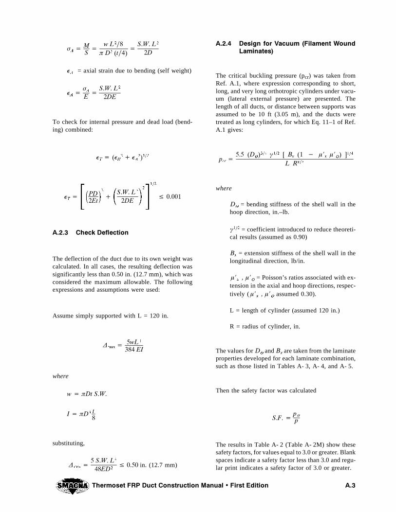
4HERMOSET &20 $UCT #ONSTRUCTION -ANUAL � &IRST %DITION !��
Æ!� -
3�
W ,���à $� �T��
�3�7� ,�
�$
�!
= axial strain due to bending (self weight)
�!�
Æ!
%�
3�7� ,�
�$%
To check for internal pressure and dead load (bend-ing) combined:
�4� ��
(
� � �!
����
�4� 0$
�%T
�
�3�7� ,�
�$%
�
���
Ì �����
!���� #HECK $EFLECTION
The deflection of the duct due to its own weight wascalculated. In all cases, the resulting deflection wassignificantly less than 0.50 in. (12.7 mm), which wasconsidered the maximum allowable. The followingexpressions and assumptions were used:
Assume simply supported with L = 120 in.
�MAX ��W,�
��� %)
where
W � Ã$T 3�7�
) � Ã$� T�
substituting,
�MAX �
� 3�7� ,�
��%$�Ì ���� in. (12.7 mm)
!���� $ESIGN FOR 6ACUUM �&ILAMENT 7OUND,AMINATES
The critical buckling pressure (pcr) was taken fromRef. A.1, where expression corresponding to short,long, and very long orthotropic cylinders under vacu-um (lateral external pressure) are presented. Thelength of all ducts, or distance between supports wasassumed to be 10 ft (3.05 m), and the ducts weretreated as long cylinders, for which Eq. 11–1 of Ref.A.1 gives:
PCR ���� �$
���� ¶��� ; "
X�� � ¿J
X¿J
� =���
, 2���
where
$�
= bending stiffness of the shell wall in thehoop direction, in.–lb.
¶��� = coefficient introduced to reduce theoreti-cal results (assumed as 0.90)
"X
= extension stiffness of the shell wall in thelongitudinal direction, lb/in.
¿JX� ¿J
�= Poisson’s ratios associated with ex-
tension in the axial and hoop directions, respec-tively ( ¿J
X� ¿J
�assumed 0.30).
L = length of cylinder (assumed 120 in.)
R = radius of cylinder, in.
The values for$�
and"Xare taken from the laminate
properties developed for each laminate combination,such as those listed in Tables A- 3, A- 4, and A- 5.
Then the safety factor was calculated
3�&� �PCR
P
The results in Table A- 2 (Table A- 2M) show thesesafety factors, for values equal to 3.0 or greater. Blankspaces indicate a safety factor less than 3.0 and regu-lar print indicates a safety factor of 3.0 or greater.
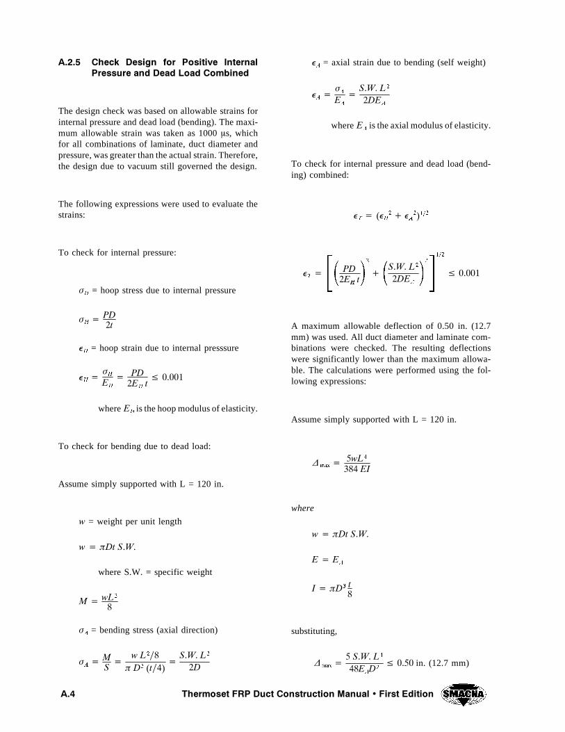
4HERMOSET &20 $UCT #ONSTRUCTION -ANUAL � &IRST %DITION!��
!���� #HECK $ESIGN FOR 0OSITIVE )NTERNAL0RESSURE AND $EAD ,OAD #OMBINED
The design check was based on allowable strains forinternal pressure and dead load (bending). The maxi-mum allowable strain was taken as 1000 ¿s, whichfor all combinations of laminate, duct diameter andpressure, was greater than the actual strain. Therefore,the design due to vacuum still governed the design.
The following expressions were used to evaluate thestrains:
To check for internal pressure:
Æ(
= hoop stress due to internal pressure
Æ(� 0$
�T
�(
= hoop strain due to internal presssure
�(�
Æ(
%(
� 0$�%
(TÌ �����
where %(
is the hoop modulus of elasticity.
To check for bending due to dead load:
Assume simply supported with L = 120 in.
W = weight per unit length
W � Ã$T 3�7�
where S.W. = specific weight
- � W,�
�
Æ!
= bending stress (axial direction)
Æ!� -
3�
W ,���à $� �T��
�3�7� ,�
�$
�!
= axial strain due to bending (self weight)
�!�
Æ!
%!
�3�7� ,�
�$%!
where %!
is the axial modulus of elasticity.
To check for internal pressure and dead load (bend-ing) combined:
�4� ��
(
� � �!
����
�4� 0$
�%(T
�
�3�7� ,�
�$%!
�
���
Ì �����
A maximum allowable deflection of 0.50 in. (12.7mm) was used. All duct diameter and laminate com-binations were checked. The resulting deflectionswere significantly lower than the maximum allowa-ble. The calculations were performed using the fol-lowing expressions:
Assume simply supported with L = 120 in.
�MAX ��W,�
��� %)
where
W � Ã$T 3�7�
% � %!
) � Ã$� T�
substituting,
�MAX �
� 3�7� ,�
��%!$�
Ì ���� in. (12.7 mm)
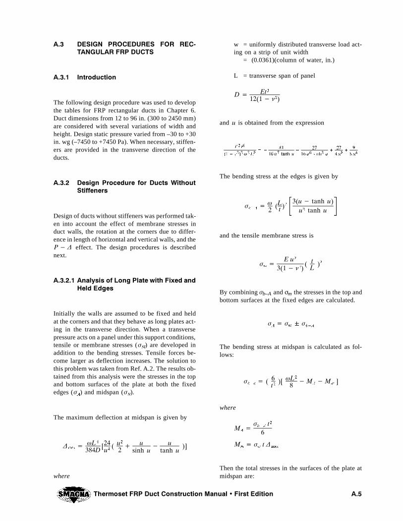
4HERMOSET &20 $UCT #ONSTRUCTION -ANUAL � &IRST %DITION !��
!�� $%3)'. 02/#%$52%3 &/2 2%# 4!.'5,!2 &20 $5#43
!���� )NTRODUCTION
The following design procedure was used to developthe tables for FRP rectangular ducts in Chapter 6.Duct dimensions from 12 to 96 in. (300 to 2450 mm)are considered with several variations of width andheight. Design static pressure varied from –30 to +30in. wg (–7450 to +7450 Pa). When necessary, stiffen-ers are provided in the transverse direction of theducts.
!���� $ESIGN 0ROCEDURE FOR $UCTS 7ITHOUT3TIFFENERS
Design of ducts without stiffeners was performed tak-en into account the effect of membrane stresses induct walls, the rotation at the corners due to differ-ence in length of horizontal and vertical walls, and the0� � effect. The design procedures is describednext.
!������ !NALYSIS OF ,ONG 0LATE WITH &IXED AND(ELD %DGES
Initially the walls are assumed to be fixed and heldat the corners and that they behave as long plates act-ing in the transverse direction. When a transversepressure acts on a panel under this support conditions,tensile or membrane stresses (Æ
-) are developed in
addition to the bending stresses. Tensile forces be-come larger as deflection increases. The solution tothis problem was taken from Ref. A.2. The results ob-tained from this analysis were the stresses in the topand bottom surfaces of the plate at both the fixededges (Æ
!) and midspan (Æ
").
The maximum deflection at midspan is given by
�MAX �
Ì,�
���$;��U�
� U�
�� U
SINH U� U
TANH U=
where
w = uniformly distributed transverse load act-ing on a strip of unit width
= (0.0361)(column of water, in.)
L = transverse span of panel
$ � %T������ À�
and U is obtained from the expression
%�T�
��� À��Ì�,�
��
��
�� U�TANH U
�
��
�� U�SINH
�U
�
��
� U�
�
�
� U�
The bending stress at the edges is given by
ÆB�!
� �
�,T �
��U� TANH UU� TANH U
and the tensile membrane stress is
ÆM �
% U�
���� À�� T,
�
By combiningÆb–A and Æm the stresses in the top andbottom surfaces at the fixed edges are calculated.
Æ!� Æ
MÆB�!
The bending stress at midspan is calculated as fol-lows:
ÆB�C
� � �T�
; Ì,�
��-
!�-M =
where
-!�
ÆB�!
T�
�
-M� Æ
MT �
MAX
Then the total stresses in the surfaces of the plate atmidspan are:
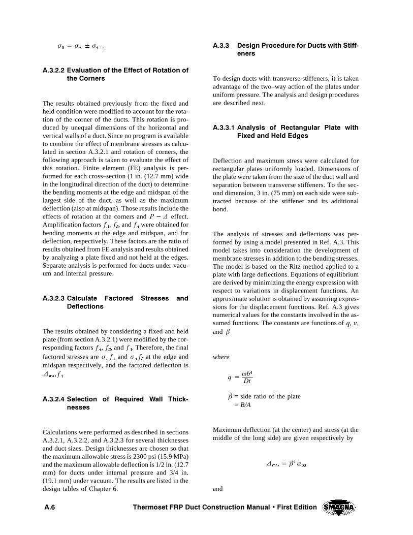
4HERMOSET &20 $UCT #ONSTRUCTION -ANUAL � &IRST %DITION!��
Æ"� Æ
MÆB�C
!������ %VALUATION OF THE %FFECT OF 2OTATION OFTHE #ORNERS
The results obtained previously from the fixed andheld condition were modified to account for the rota-tion of the corner of the ducts. This rotation is pro-duced by unequal dimensions of the horizontal andvertical walls of a duct. Since no program is availableto combine the effect of membrane stresses as calcu-lated in section A.3.2.1 and rotation of corners, thefollowing approach is taken to evaluate the effect ofthis rotation. Finite element (FE) analysis is per-formed for each cross–section (1 in. (12.7 mm) widein the longitudinal direction of the duct) to determinethe bending moments at the edge and midspan of thelargest side of the duct, as well as the maximumdeflection (also at midspan). Those results include theeffects of rotation at the corners and0� � effect.Amplification factorsF
!, F
", and F
�were obtained for
bending moments at the edge and midspan, and fordeflection, respectively. These factors are the ratio ofresults obtained from FE analysis and results obtainedby analyzing a plate fixed and not held at the edges.Separate analysis is performed for ducts under vacu-um and internal pressure.
!������ #ALCULATE &ACTORED 3TRESSES AND$EFLECTIONS
The results obtained by considering a fixed and heldplate (from section A.3.2.1) were modified by the cor-responding factorsF
!, F
", and F
�. Therefore, the final
factored stresses areÆ!F!
and Æ!F"
at the edge andmidspan respectively, and the factored deflection is�
MAXF�
!������ 3ELECTION OF 2EQUIRED 7ALL 4HICK NESSES
Calculations were performed as described in sectionsA.3.2.1, A.3.2.2, and A.3.2.3 for several thicknessesand duct sizes. Design thicknesses are chosen so thatthe maximum allowable stress is 2300 psi (15.9 MPa)and the maximum allowable deflection is 1/2 in. (12.7mm) for ducts under internal pressure and 3/4 in.(19.1 mm) under vacuum. The results are listed in thedesign tables of Chapter 6.
!���� $ESIGN 0ROCEDURE FOR $UCTS WITH 3TIFF ENERS
To design ducts with transverse stiffeners, it is takenadvantage of the two–way action of the plates underuniform pressure. The analysis and design proceduresare described next.
!������ !NALYSIS OF 2ECTANGULAR 0LATE WITH&IXED AND (ELD %DGES
Deflection and maximum stress were calculated forrectangular plates uniformly loaded. Dimensions ofthe plate were taken from the size of the duct wall andseparation between transverse stiffeners. To the sec-ond dimension, 3 in. (75 mm) on each side were sub-tracted because of the stiffener and its additionalbond.
The analysis of stresses and deflections was per-formed by using a model presented in Ref. A.3. Thismodel takes into consideration the development ofmembrane stresses in addition to the bending stresses.The model is based on the Ritz method applied to aplate with large deflections. Equations of equilibriumare derived by minimizing the energy expression withrespect to variations in displacement functions. Anapproximate solution is obtained by assuming expres-sions for the displacement functions. Ref. A.3 givesnumerical values for the constants involved in the as-sumed functions. The constants are functions ofQ, À,and µ
where
Q � ÌB�
$T
µ = side ratio of the plate= B/A
Maximum deflection (at the center) and stress (at themiddle of the long side) are given respectively by
�MAX � µ� ´��
and
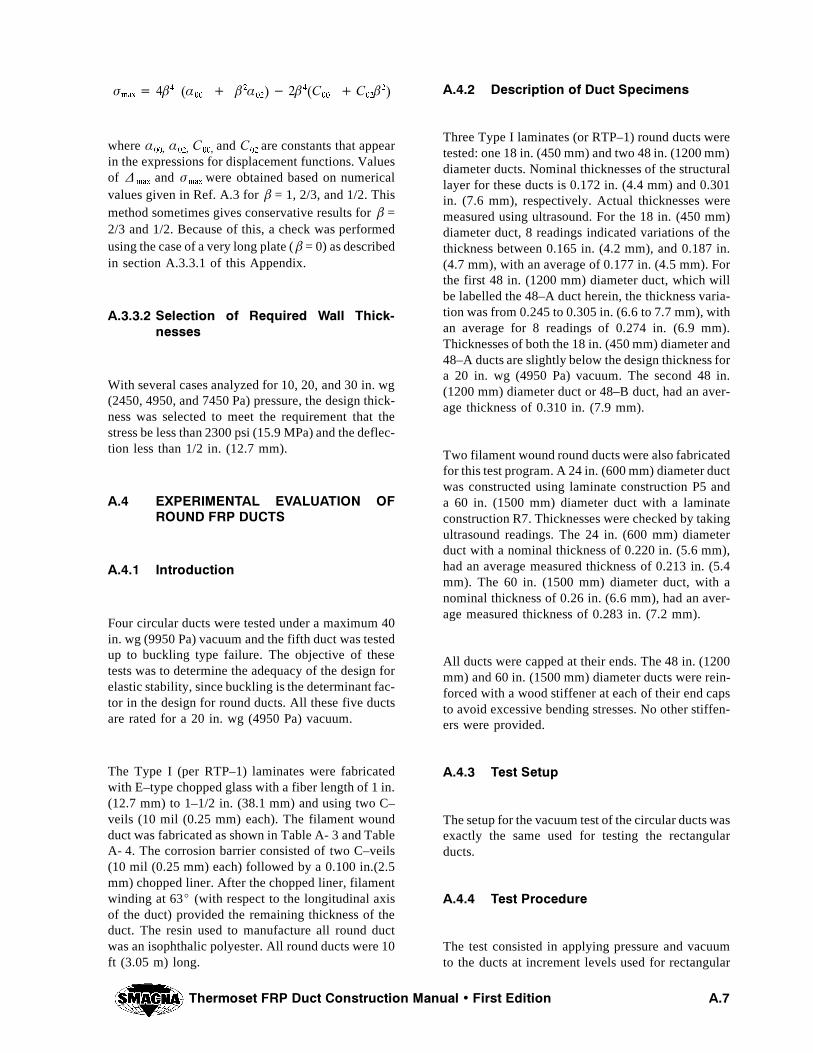
4HERMOSET &20 $UCT #ONSTRUCTION -ANUAL � &IRST %DITION !��
ÆMAX � �µ� �´��
� µ�´��� �µ��#
��� #
��µ�
where ´��, ´��, #��, and #
��are constants that appear
in the expressions for displacement functions. Valuesof �
MAXand Æ
MAXwere obtained based on numerical
values given in Ref. A.3 for µ = 1, 2/3, and 1/2. Thismethod sometimes gives conservative results for µ =2/3 and 1/2. Because of this, a check was performedusing the case of a very long plate ( µ = 0) as describedin section A.3.3.1 of this Appendix.
!������ 3ELECTION OF 2EQUIRED 7ALL 4HICK NESSES
With several cases analyzed for 10, 20, and 30 in. wg(2450, 4950, and 7450 Pa) pressure, the design thick-ness was selected to meet the requirement that thestress be less than 2300 psi (15.9 MPa) and the deflec-tion less than 1/2 in. (12.7 mm).
!�� %80%2)-%.4!, %6!,5!4)/. /&2/5.$ &20 $5#43
!���� )NTRODUCTION
Four circular ducts were tested under a maximum 40in. wg (9950 Pa) vacuum and the fifth duct was testedup to buckling type failure. The objective of thesetests was to determine the adequacy of the design forelastic stability, since buckling is the determinant fac-tor in the design for round ducts. All these five ductsare rated for a 20 in. wg (4950 Pa) vacuum.
The Type I (per RTP–1) laminates were fabricatedwith E–type chopped glass with a fiber length of 1 in.(12.7 mm) to 1–1/2 in. (38.1 mm) and using two C–veils (10 mil (0.25 mm) each). The filament woundduct was fabricated as shown in Table A- 3 and TableA- 4. The corrosion barrier consisted of two C–veils(10 mil (0.25 mm) each) followed by a 0.100 in.(2.5mm) chopped liner. After the chopped liner, filamentwinding at 63̂ (with respect to the longitudinal axisof the duct) provided the remaining thickness of theduct. The resin used to manufacture all round ductwas an isophthalic polyester. All round ducts were 10ft (3.05 m) long.
!���� $ESCRIPTION OF $UCT 3PECIMENS
Three Type I laminates (or RTP–1) round ducts weretested: one 18 in. (450 mm) and two 48 in. (1200 mm)diameter ducts. Nominal thicknesses of the structurallayer for these ducts is 0.172 in. (4.4 mm) and 0.301in. (7.6 mm), respectively. Actual thicknesses weremeasured using ultrasound. For the 18 in. (450 mm)diameter duct, 8 readings indicated variations of thethickness between 0.165 in. (4.2 mm), and 0.187 in.(4.7 mm), with an average of 0.177 in. (4.5 mm). Forthe first 48 in. (1200 mm) diameter duct, which willbe labelled the 48–A duct herein, the thickness varia-tion was from 0.245 to 0.305 in. (6.6 to 7.7 mm), withan average for 8 readings of 0.274 in. (6.9 mm).Thicknesses of both the 18 in. (450 mm) diameter and48–A ducts are slightly below the design thickness fora 20 in. wg (4950 Pa) vacuum. The second 48 in.(1200 mm) diameter duct or 48–B duct, had an aver-age thickness of 0.310 in. (7.9 mm).
Two filament wound round ducts were also fabricatedfor this test program. A 24 in. (600 mm) diameter ductwas constructed using laminate construction P5 anda 60 in. (1500 mm) diameter duct with a laminateconstruction R7. Thicknesses were checked by takingultrasound readings. The 24 in. (600 mm) diameterduct with a nominal thickness of 0.220 in. (5.6 mm),had an average measured thickness of 0.213 in. (5.4mm). The 60 in. (1500 mm) diameter duct, with anominal thickness of 0.26 in. (6.6 mm), had an aver-age measured thickness of 0.283 in. (7.2 mm).
All ducts were capped at their ends. The 48 in. (1200mm) and 60 in. (1500 mm) diameter ducts were rein-forced with a wood stiffener at each of their end capsto avoid excessive bending stresses. No other stiffen-ers were provided.
!���� 4EST 3ETUP
The setup for the vacuum test of the circular ducts wasexactly the same used for testing the rectangularducts.
!���� 4EST 0ROCEDURE
The test consisted in applying pressure and vacuumto the ducts at increment levels used for rectangular
4HERMOSET &20 $UCT #ONSTRUCTION -ANUAL � &IRST %DITION!��
ducts. Since the ducts were designed for 20 in. wg(4950 Pa) vacuum, they were subjected to a maxi-mum of 40 in. wg (9950 Pa) vacuum with exceptionof the 48–B duct which was loaded to a higher va-cuum. While the vacuum was being applied, the ductswere inspected for any indication of instability orbuckling. Strains were measured for all ducts underboth pressure and vacuum load conditions.
!���� 3TRESSES AND 3TRAINS
Strains and resultant stresses were obtained on allround ducts at all load increments. Resultant strainsclosely coincide with the theoretical strains as givenby the traditional formulas of PR/t and PR/2t for hoopand axial stresses respectively; where P is the pres-sure, R is the radius of the cylinder, and t is the wallthickness.
!���� 4EST 2ESULTS
All round ducts were initially subjected to 50 in. wg(12.4 kPa) pressure. The strain levels measured wereall very low relative to acceptable standard of 1000¿s used throughout most of the fiberglass industry.
Under vacuum, all ducts were subjected to 40 in. wg.(9950 Pa). The 18, 24, and 60 in. (450, 600, and 1500mm) diameter ducts resisted the maximum vacuumwithout any indication of elastic instability or buck-ling. There was no indication of any other type ofdamage in any of these three ducts. Strains measuredon the 24 in. (600 mm) diameter duct were very small,well below the 1000¿s limit given above. This con-firms that strain is not the controlling design factorfor circular ducts subjected to vacuum.
The 48–A duct was also loaded to the maximum valueof 40 in. wg (9950 Pa) vacuum. However, this ductbuckled suddenly as the maximum vacuum wasreached. The buckling occurred at the mid–length ofthe duct and over an area of approximately 180^ cir-cumferential direction and 36 in. (900 mm) in axialdirection with the depression of approximately 5 in.(125 mm) at its deepest point. The buckled shape hada total of 2 lobes separated approximately 90^ apart.As noted earlier, the shell for the 48 in. (1200 mm)diameter duct was determined to be thinner than the
nominal design thickness. The 48–B duct with a shellthickness of 0.310 in. (7.9 mm) was loaded up to fai-lure. This duct buckled at 67 in. wg (16.7 kPa) vacu-um, which is significantly higher than the design 20in. wg (4950 Pa) vacuum.
Strains measured in the duct were well below themaximum allowable. Again it was confirmed thatelastic instability governs the design of these roundducts rather than strength.
!���� #ONCLUSIONS FOR 2OUND $UCT
Based on the experimental results reported by Dr.Plecnik, the following conclusions were reached:
1. Round fiberglass duct under pressure or vac-uum may be accurately analyzed for stressesand strains using conventional PR/t andPR/2t for hoop and axial stresses respective-ly.
2. Under typical pressure conditions, the fiber-glass round duct is subjected to very lowstrain and stress levels. However, significantstress/strain levels may occur if additionalwind, seismic or other type of loads are con-sidered.
3. Under vacuum loading, buckling is the con-trolling design condition since stresses andstrains are generally very low. The bucklinganalysis as presented above accurately pre-dicts the buckling failure of round ducting.
4. The additional stresses or strains producedby different types of support conditions mustbe considered when analyzing localizedstress conditions in round ducting.
5. When applicable, stresses induced by windor seismic loads must be added to the analy-sis presented.
6. Based on the test results, it is recommendedthat the analytical procedures described ear-lier be accepted as a reasonable design meth-od for round fiberglass ducting.
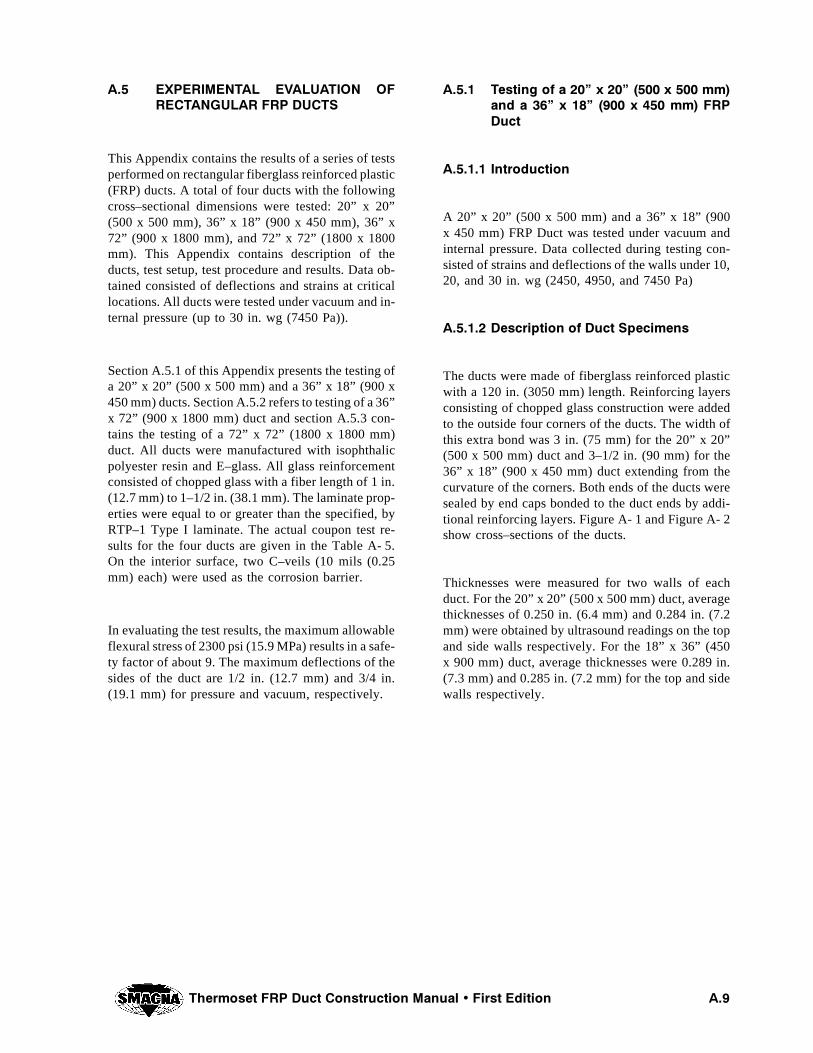
4HERMOSET &20 $UCT #ONSTRUCTION -ANUAL � &IRST %DITION !��
!�� %80%2)-%.4!, %6!,5!4)/. /&2%#4!.'5,!2 &20 $5#43
This Appendix contains the results of a series of testsperformed on rectangular fiberglass reinforced plastic(FRP) ducts. A total of four ducts with the followingcross–sectional dimensions were tested: 20” x 20”(500 x 500 mm), 36” x 18” (900 x 450 mm), 36” x72” (900 x 1800 mm), and 72” x 72” (1800 x 1800mm). This Appendix contains description of theducts, test setup, test procedure and results. Data ob-tained consisted of deflections and strains at criticallocations. All ducts were tested under vacuum and in-ternal pressure (up to 30 in. wg (7450 Pa)).
Section A.5.1 of this Appendix presents the testing ofa 20” x 20” (500 x 500 mm) and a 36” x 18” (900 x450 mm) ducts. Section A.5.2 refers to testing of a 36”x 72” (900 x 1800 mm) duct and section A.5.3 con-tains the testing of a 72” x 72” (1800 x 1800 mm)duct. All ducts were manufactured with isophthalicpolyester resin and E–glass. All glass reinforcementconsisted of chopped glass with a fiber length of 1 in.(12.7 mm) to 1–1/2 in. (38.1 mm). The laminate prop-erties were equal to or greater than the specified, byRTP–1 Type I laminate. The actual coupon test re-sults for the four ducts are given in the Table A- 5.On the interior surface, two C–veils (10 mils (0.25mm) each) were used as the corrosion barrier.
In evaluating the test results, the maximum allowableflexural stress of 2300 psi (15.9 MPa) results in a safe-ty factor of about 9. The maximum deflections of thesides of the duct are 1/2 in. (12.7 mm) and 3/4 in.(19.1 mm) for pressure and vacuum, respectively.
!���� 4ESTING OF A ��ì X ��ì ���� X ��� MMAND A ��ì X ��ì ���� X ��� MM &20$UCT
!������ )NTRODUCTION
A 20” x 20” (500 x 500 mm) and a 36” x 18” (900x 450 mm) FRP Duct was tested under vacuum andinternal pressure. Data collected during testing con-sisted of strains and deflections of the walls under 10,20, and 30 in. wg (2450, 4950, and 7450 Pa)
!������ $ESCRIPTION OF $UCT 3PECIMENS
The ducts were made of fiberglass reinforced plasticwith a 120 in. (3050 mm) length. Reinforcing layersconsisting of chopped glass construction were addedto the outside four corners of the ducts. The width ofthis extra bond was 3 in. (75 mm) for the 20” x 20”(500 x 500 mm) duct and 3–1/2 in. (90 mm) for the36” x 18” (900 x 450 mm) duct extending from thecurvature of the corners. Both ends of the ducts weresealed by end caps bonded to the duct ends by addi-tional reinforcing layers. Figure A- 1 and Figure A- 2show cross–sections of the ducts.
Thicknesses were measured for two walls of eachduct. For the 20” x 20” (500 x 500 mm) duct, averagethicknesses of 0.250 in. (6.4 mm) and 0.284 in. (7.2mm) were obtained by ultrasound readings on the topand side walls respectively. For the 18” x 36” (450x 900 mm) duct, average thicknesses were 0.289 in.(7.3 mm) and 0.285 in. (7.2 mm) for the top and sidewalls respectively.
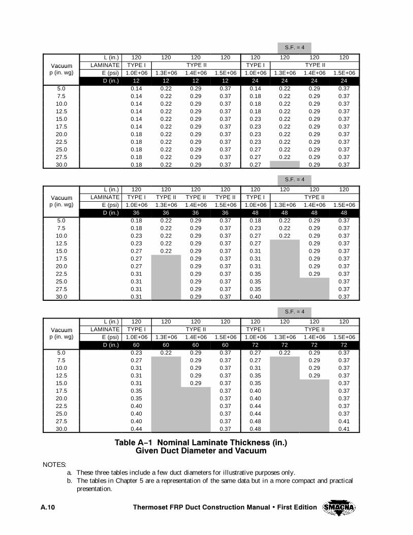
7KHUPRVHW )53 'XFW &RQVWUXFWLRQ 0DQXDO � )LUVW (GLWLRQ$���
S.F. = 4
L (in.) 120 120 120 120 120 120 120 120
Vacuum LAMINATE TYPE I TYPE II TYPE I TYPE IIVacuump (in. wg) E (psi) 1.0E+06 1.3E+06 1.4E+06 1.5E+06 1.0E+06 1.3E+06 1.4E+06 1.5E+06( g)
D (in.) 12 12 12 12 24 24 24 245.0 0.14 0.22 0.29 0.37 0.14 0.22 0.29 0.377.5 0.14 0.22 0.29 0.37 0.18 0.22 0.29 0.3710.0 0.14 0.22 0.29 0.37 0.18 0.22 0.29 0.3712.5 0.14 0.22 0.29 0.37 0.18 0.22 0.29 0.3715.0 0.14 0.22 0.29 0.37 0.23 0.22 0.29 0.3717.5 0.14 0.22 0.29 0.37 0.23 0.22 0.29 0.3720.0 0.18 0.22 0.29 0.37 0.23 0.22 0.29 0.3722.5 0.18 0.22 0.29 0.37 0.23 0.22 0.29 0.3725.0 0.18 0.22 0.29 0.37 0.27 0.22 0.29 0.3727.5 0.18 0.22 0.29 0.37 0.27 0.22 0.29 0.3730.0 0.18 0.22 0.29 0.37 0.27 0.29 0.37
S.F. = 4
L (in.) 120 120 120 120 120 120 120 120
Vacuum LAMINATE TYPE I TYPE II TYPE II TYPE II TYPE I TYPE IIVacuump (in. wg) E (psi) 1.0E+06 1.3E+06 1.4E+06 1.5E+06 1.0E+06 1.3E+06 1.4E+06 1.5E+06( g)
D (in.) 36 36 36 36 48 48 48 485.0 0.18 0.22 0.29 0.37 0.18 0.22 0.29 0.377.5 0.18 0.22 0.29 0.37 0.23 0.22 0.29 0.3710.0 0.23 0.22 0.29 0.37 0.27 0.22 0.29 0.3712.5 0.23 0.22 0.29 0.37 0.27 0.29 0.3715.0 0.27 0.22 0.29 0.37 0.31 0.29 0.3717.5 0.27 0.29 0.37 0.31 0.29 0.3720.0 0.27 0.29 0.37 0.31 0.29 0.3722.5 0.31 0.29 0.37 0.35 0.29 0.3725.0 0.31 0.29 0.37 0.35 0.3727.5 0.31 0.29 0.37 0.35 0.3730.0 0.31 0.29 0.37 0.40 0.37
S.F. = 4
L (in.) 120 120 120 120 120 120 120 120
Vacuum LAMINATE TYPE I TYPE II TYPE I TYPE IIVacuump (in. wg) E (psi) 1.0E+06 1.3E+06 1.4E+06 1.5E+06 1.0E+06 1.3E+06 1.4E+06 1.5E+06( g)
D (in.) 60 60 60 60 72 72 72 725.0 0.23 0.22 0.29 0.37 0.27 0.22 0.29 0.377.5 0.27 0.29 0.37 0.27 0.29 0.3710.0 0.31 0.29 0.37 0.31 0.29 0.3712.5 0.31 0.29 0.37 0.35 0.29 0.3715.0 0.31 0.29 0.37 0.35 0.3717.5 0.35 0.37 0.40 0.3720.0 0.35 0.37 0.40 0.3722.5 0.40 0.37 0.44 0.3725.0 0.40 0.37 0.44 0.3727.5 0.40 0.37 0.48 0.4130.0 0.44 0.37 0.48 0.41
7DEOH $ï� 1RPLQDO /DPLQDWH 7KLFNQHVV �LQ��*LYHQ 'XFW 'LDPHWHU DQG 9DFXXP
NOTES:a. These three tables include a few duct diameters for illustrative purposes only.b. The tables in Chapter 5 are a representation of the same data but in a more compact and practical
presentation.
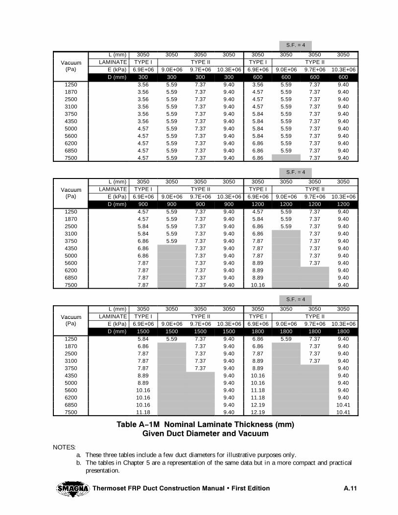
7KHUPRVHW )53 'XFW &RQVWUXFWLRQ 0DQXDO � )LUVW (GLWLRQ $���
S.F. = 4
L (mm) 3050 3050 3050 3050 3050 3050 3050 3050
Vacuum LAMINATE TYPE I TYPE II TYPE I TYPE IIVacuum(Pa) E (kPa) 6.9E+06 9.0E+06 9.7E+06 10.3E+06 6.9E+06 9.0E+06 9.7E+06 10.3E+06( )
D (mm) 300 300 300 300 600 600 600 6001250 3.56 5.59 7.37 9.40 3.56 5.59 7.37 9.401870 3.56 5.59 7.37 9.40 4.57 5.59 7.37 9.402500 3.56 5.59 7.37 9.40 4.57 5.59 7.37 9.403100 3.56 5.59 7.37 9.40 4.57 5.59 7.37 9.403750 3.56 5.59 7.37 9.40 5.84 5.59 7.37 9.404350 3.56 5.59 7.37 9.40 5.84 5.59 7.37 9.405000 4.57 5.59 7.37 9.40 5.84 5.59 7.37 9.405600 4.57 5.59 7.37 9.40 5.84 5.59 7.37 9.406200 4.57 5.59 7.37 9.40 6.86 5.59 7.37 9.406850 4.57 5.59 7.37 9.40 6.86 5.59 7.37 9.407500 4.57 5.59 7.37 9.40 6.86 7.37 9.40
S.F. = 4
L (mm) 3050 3050 3050 3050 3050 3050 3050 3050
Vacuum LAMINATE TYPE I TYPE II TYPE I TYPE IIVacuum(Pa) E (kPa) 6.9E+06 9.0E+06 9.7E+06 10.3E+06 6.9E+06 9.0E+06 9.7E+06 10.3E+06( )
D (mm) 900 900 900 900 1200 1200 1200 12001250 4.57 5.59 7.37 9.40 4.57 5.59 7.37 9.401870 4.57 5.59 7.37 9.40 5.84 5.59 7.37 9.402500 5.84 5.59 7.37 9.40 6.86 5.59 7.37 9.403100 5.84 5.59 7.37 9.40 6.86 7.37 9.403750 6.86 5.59 7.37 9.40 7.87 7.37 9.404350 6.86 7.37 9.40 7.87 7.37 9.405000 6.86 7.37 9.40 7.87 7.37 9.405600 7.87 7.37 9.40 8.89 7.37 9.406200 7.87 7.37 9.40 8.89 9.406850 7.87 7.37 9.40 8.89 9.407500 7.87 7.37 9.40 10.16 9.40
S.F. = 4
L (mm) 3050 3050 3050 3050 3050 3050 3050 3050
Vacuum LAMINATE TYPE I TYPE II TYPE I TYPE IIVacuum(Pa) E (kPa) 6.9E+06 9.0E+06 9.7E+06 10.3E+06 6.9E+06 9.0E+06 9.7E+06 10.3E+06( )
D (mm) 1500 1500 1500 1500 1800 1800 1800 18001250 5.84 5.59 7.37 9.40 6.86 5.59 7.37 9.401870 6.86 7.37 9.40 6.86 7.37 9.402500 7.87 7.37 9.40 7.87 7.37 9.403100 7.87 7.37 9.40 8.89 7.37 9.403750 7.87 7.37 9.40 8.89 9.404350 8.89 9.40 10.16 9.405000 8.89 9.40 10.16 9.405600 10.16 9.40 11.18 9.406200 10.16 9.40 11.18 9.406850 10.16 9.40 12.19 10.417500 11.18 9.40 12.19 10.41
7DEOH $ï�0 1RPLQDO /DPLQDWH 7KLFNQHVV �PP�*LYHQ 'XFW 'LDPHWHU DQG 9DFXXP
NOTES:a. These three tables include a few duct diameters for illustrative purposes only.b. The tables in Chapter 5 are a representation of the same data but in a more compact and practical
presentation.
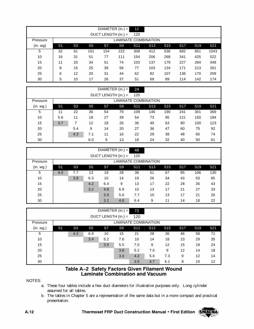
7KHUPRVHW )53 'XFW &RQVWUXFWLRQ 0DQXDO � )LUVW (GLWLRQ$���
DIAMETER (in.) = 12 12
DUCT LENGTH (in.) = 120
Pressure LAMINATE COMBINATION
(in. wg) S1 S3 S5 S7 S9 S11 S13 S15 S17 S19 S21
5 32 61 101 154 222 308 412 536 682 851 1043
10 16 31 51 77 111 154 206 268 341 425 522
15 11 20 34 51 74 103 137 179 227 284 348
20 8 15 25 39 56 77 103 134 171 213 261
25 6 12 20 31 44 62 82 107 136 170 209
30 5 10 17 26 37 51 69 89 114 142 174
DIAMETER (in.) = 24DUCT LENGTH (in.) = 120
Pressure LAMINATE COMBINATION
(in. wg.) S1 S3 S5 S7 S9 S11 S13 S15 S17 S19 S21
5 11 22 36 54 79 109 146 190 241 301 369
10 5.6 11 18 27 39 54 73 95 121 150 184
15 3.7 7 12 18 26 36 49 63 80 100 123
20 5.4 9 14 20 27 36 47 60 75 92
25 4.3 7.1 11 16 22 29 38 48 60 74
30 6.0 9 13 18 24 32 40 50 61
DIAMETER (in.) = 48DUCT LENGTH (in.) = 120
Pressure LAMINATE COMBINATION
(in. wg.) S1 S3 S5 S7 S9 S11 S13 S15 S17 S19 S21
5 4.0 7.7 13 19 28 38 51 67 85 106 130
10 3.8 6.3 10 14 19 26 34 43 53 65
15 4.2 6.4 9 13 17 22 28 35 43
20 3.2 4.8 6.9 10 13 17 21 27 33
25 3.9 5.6 7.7 10 13 17 21 26
30 3.2 4.6 6.4 9 11 14 18 22
DIAMETER (in.) = 72DUCT LENGTH (in.) = 120
Pressure LAMINATE COMBINATION
(in. wg.) S1 S3 S5 S7 S9 S11 S13 S15 S17 S19 S21
5 4.2 6.9 10 15 21 28 36 46 58 71
10 3.4 5.2 7.6 10 14 18 23 29 35
15 3.5 5.0 7.0 9 12 15 19 24
20 3.8 5.2 7.0 9 12 14 18
25 3.0 4.2 5.6 7.3 9 12 14
30 3.5 4.7 6.1 8 10 12
7DEOH $ï� 6DIHW\ )DFWRUV *LYHQ )LODPHQW :RXQG/DPLQDWH &RPELQDWLRQ DQG 9DFXXP
NOTES:a. These four tables include a few duct diameters for illustrative purposes only. Long cylinder
assumed for all tables.b. The tables in Chapter 5 are a representation of the same data but in a more compact and practical
presentation.

7KHUPRVHW )53 'XFW &RQVWUXFWLRQ 0DQXDO � )LUVW (GLWLRQ $���
DIAMETER (mm) = 300 300
DUCT LENGTH (mm) = 3050
Pressure LAMINATE COMBINATION
(Pa) S1 S3 S5 S7 S9 S11 S13 S15 S17 S19 S21
1250 32 61 101 154 222 308 412 536 682 851 1043
2500 16 31 51 77 111 154 206 268 341 425 522
3750 11 20 34 51 74 103 137 179 227 284 348
5000 8 15 25 39 56 77 103 134 171 213 261
6250 6 12 20 31 44 62 82 107 136 170 209
7500 5 10 17 26 37 51 69 89 114 142 174
DIAMETER (mm) = 600DUCT LENGTH (mm) = 3050
Pressure LAMINATE COMBINATION
(Pa) S1 S3 S5 S7 S9 S11 S13 S15 S17 S19 S21
1250 11 22 36 54 79 109 146 190 241 301 369
2500 5.6 11 18 27 39 54 73 95 121 150 184
3750 3.7 7 12 18 26 36 49 63 80 100 123
5000 5.4 9 14 20 27 36 47 60 75 92
6250 4.3 7.1 11 16 22 29 38 48 60 74
7500 6.0 9 13 18 24 32 40 50 61
DIAMETER (mm) = 1200 1200
DUCT LENGTH (mm) = 3050
Pressure LAMINATE COMBINATION
(Pa) S1 S3 S5 S7 S9 S11 S13 S15 S17 S19 S21
1250 4.0 7.7 13 19 28 38 51 67 85 106 130
2500 3.8 6.3 10 14 19 26 34 43 53 65
3750 4.2 6.4 9 13 17 22 28 35 43
5000 3.2 4.8 6.9 10 13 17 21 27 33
6250 3.9 5.6 7.7 10 13 17 21 26
7500 3.2 4.6 6.4 9 11 14 18 22
DIAMETER (mm) = 1800
DUCT LENGTH (mm) = 3050
Pressure LAMINATE COMBINATION
(Pa) S1 S3 S5 S7 S9 S11 S13 S15 S17 S19 S21
1250 4.2 6.9 10 15 21 28 36 46 58 71
2500 3.4 5.2 7.6 10 14 18 23 29 35
3750 3.5 5.0 7.0 9 12 15 19 24
5000 3.8 5.2 7.0 9 12 14 18
6250 3.0 4.2 5.6 7.3 9 12 14
7500 3.5 4.7 6.1 8 10 12
7DEOH $ï�0 6DIHW\ )DFWRUV *LYHQ )LODPHQW :RXQG/DPLQDWH &RPELQDWLRQ DQG 9DFXXP
NOTES:a. These four tables include a few duct diameters for illustrative purposes only. Long cylinder
assumed for all tables.b. The tables in Chapter 5 are a representation of the same data but in a more compact and practical
presentation.

7KHUPRVHW )53 'XFW &RQVWUXFWLRQ 0DQXDO � )LUVW (GLWLRQ$���
),*85( $ï� &5266 6(&7,21 2) $ ��µ ; ��µ ���� ; ��� PP� '8&7
ADDITIONALBOND
DUCTTHICKNESS
TOP PANEL
SID
EP
AN
EL
SG = STRAIN GAGE
SG- 3SG- 2SG- 1
SG- 5
SG- 4
3 in. (75 mm)
1/2" (12.7 mm)MINIMUM CORNER RADIUS
),*85( $ï� &5266 6(&7,21 2) $ ��µ ; ��µ ���� ; ��� PP� '8&7
ADDITIONALBOND
DUCTTHICKNESS
TOP PANELS
IDE
PA
NE
L
SG = STRAIN GAGE
SG- 3SG- 2SG- 1
SG- 5
SG- 4
3• 1/2 in.(90 mm)
1" (25.4 mm)MINIMUM CORNER RADIUS

4HERMOSET &20 $UCT #ONSTRUCTION -ANUAL � &IRST %DITION !���
!������ 4EST 3ETUP
All the duct specimens were subjected to both internalpressure and vacuum. Using air pressure or vacuumpumps, the appropriate pressure and vacuum were ap-plied to each duct at pre–determined levels. FigureA- 3 provides a schematic of the test setup. A manom-eter was used to control both the vacuum and pres-sure.
A total of five strain gages (SG) were placed on eachduct specimen. All gages were located at mid lengthof the ducts. Three gages were placed on the top wall:SG–1 was in the middle, SG–2 was placed approxi-mately 1 in. from the additional bond at the corners,and SG–3 in the center of the additional bond. GageSG–4 was installed on the round corner. SG–5 wasplaced in the middle of one of the side walls. Allgages were oriented in the transverse direction.
Deflections were measured at the center of both thetop wall (next to SG–1) and the side wall (next toSG–5). To measure deflections, fixed horizontal andvertical reference lines were used parallel to the topwall and side wall, respectively.
!������ 4EST 0ROCEDURE
The tests consisted of applying vacuum and internalpressure to the ducts. Data consisted of deflectionsand strains measured at location described above. The20” x 20” (500 x 500 mm) duct was tested first undervacuum and then under pressure and the 36” x 18”(900 x 450 mm) duct was tested first under pressureand then under vacuum.
Initial deflection and strain readings were taken whenthe ducts were under zero gage pressure. These read-ings become the reference or zero readings. Then vac-uum or pressure were applied up to 10 in. wg (2450Pa). Pressure was maintained constant while a secondset of deflection and strain readings were taken. Thenext step consisted of increasing the vacuum or pres-sure from 10 in. wg (2450 Pa) to 20 in. wg (4950 Pa),where readings were again taken while the pressurewas kept constant. The same procedure was repeatedfor a vacuum or pressure of 30 in. wg (7450 Pa). Atthis point, the duct was visually examined for any da-
mage. Finally, the pressure or vacuum was reducedback to zero.
!������ 4EST 2ESULTS FOR ��ì X ��ì ���� X ���MM $UCT
Resultant deflections and strains were obtained bysubtracting the zero reading from the readings takenat 10, 20, and 30 in. wg (2450, 4950, and 7450 Pa)respectively. The maximum strain of 2160 microstrains (¿s) occurs at the duct’s corner (SG–4) undera 30 in. wg (7450 Pa) vacuum. This strain is equiva-lent to 2160 psi (14.9 MPa) assuming a modulus ofelasticity of 1x10⁶ psi (6.9x10³ MPa). This stress isless than the allowable of 2300 psi (15.9 MPa). Allother stresses were well below this allowable stress.For 20 in. wg (4950 Pa) pressure, the maximum strainwas 1607¿s, which corresponds to a stress of 1607psi (11.1 MPa).
A significant fact is the difference between strains re-corded by SG–1 and SG–5. Even though theoreticallyboth strains should be the same for a square duct,SG–5 gave strains approximately half of those re-corded by SG–1. This implies a thickness variationin the walls of the duct. The top wall deflected 0.31in. (7.9 mm) whereas the side wall only 0.14 in. (3.6mm) under 30 in. wg (7450 Pa) pressure. However,these deflections are considered reasonable for thisduct considering that the deflection limit is 3/4 in.(19.1 mm) at the design condition of 10 in. wg (2450Pa).
Very similar results were obtained for the vacuum andthe internal pressure tests. The only difference is thechange of sign for the strains and change of directionfor deflections.
!������ 4EST 2ESULTS FOR ��ì X ��ì ���� X ���MM $UCT
Analysis of the strains showed the effect of the differ-ence in length of the long side and short side of therectangular cross section. In this case, when vacuumis applied, SG–1 is under compression and SG–5 un-der tension. (This is in contrast to what was observedfor the square duct where both SG–1 and SG–5 indi-cate compression strain under vacuum.) The largestrecorded strain of 1697¿s is at the corner (SG–4), but
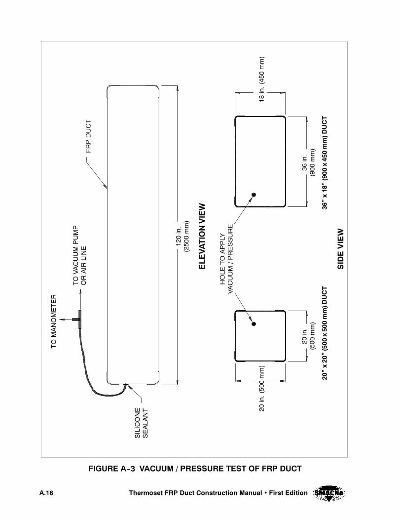
4HERMOSET &20 $UCT #ONSTRUCTION -ANUAL � &IRST %DITION!���
&)'52% ! � 6!#55- � 02%3352% 4%34 /& &20 $5#4
%,%
6!4)/.6)%7
3)$
%6)%7
��ìX��
���
X��
�MM$
5#4
��ìX��
���
X��
�MM$
5#4
��IN�
����
MM
��IN����
�MM
��IN����
�MM
��IN�
����
MM
���IN�
����
�MM
(/,%
4/
!00,9
6!#55-
�02%3352%
3),)#
/.%
3%!,!
.4
4/
-!./-%4%2
4/
6!#55-
05-0
/2
!)2
,).%
&20$5#4
4HERMOSET &20 $UCT #ONSTRUCTION -ANUAL � &IRST %DITION !���
even at 30 in. wg (7450 Pa) vacuum, the strain re-mains below the maximum allowable.
Deflections are more critical than strains for this duct.Under vacuum of 30 in. wg (7450 Pa), the top sidehad a deflection of 0.84 in. (21.3 mm) at the center.The maximum allowable deflection for vacuum of3/4 in. (19 mm) is exceeded by 12%. At 20 in. wg(4950 Pa) vacuum, the deflection is 0.56 in. (14.2mm), which is below the maximum limit. The effectof long side to short side length ratio is also evidenton deflections. The short side deflected only 0.12in.(3 mm) and 0.08 in. (2 mm) at 30 in. wg (7450 Pa)and 20 in. wg (4950 Pa) vacuum, respectively. At thedesign pressure/vacuum of 10 in. wg (2450 Pa) for aduct with a thickness equivalent to this 36” x 18” (900x 450 mm) duct, deflections were significantly lowerthan the maximum limits. Under 10 in. wg (2450 Pa)vacuum, the deflection of the top panel was 0.27 in.(6.9 mm), which is below the 0.75 in. (19.1 mm) lim-it.
The length of additional bonds at the corners can beconsidered adequate. This may be concluded by anal-ysis of the strains recorded by SG–2, which is nearthe end of the corner bond. Strains here are verysmall. This indicates that the bond has been extendedto approximately the point of inflection where bend-ing stresses are minimum.
!���� 4ESTING OF A ��ì X ��ì ���� X ���� MM&20 $UCT
!������ )NTRODUCTION
A 36” x 72” (900 x 1800 mm) FRP duct was testedunder vacuum and internal pressure (maximum of 30in. wg (7450 Pa)). This section contains a descriptionof the specimen, test setup and procedure, and results.This type of duct is rated for a design pressure/vacu-um of 10 in. wg (2450 Pa), and its design thicknessis 0.387 in. (9.8 mm) for a maximum stiffener spacingof 54 in. (1350 mm), or thickness of 0.301 in. (7.6mm) for a stiffener spacing of 42 in. (1050 mm).
!������ $ESCRIPTION OF $UCT 3PECIMEN
The 98 in. (2500 mm) long FRP duct had a rectangu-lar cross section of 36 in. x 72 in. (900 x 1800 mm).The duct was reinforced at its mid length using an ex-ternal 2 x 4 (50 x 100 mm) wood stiffener with 1/4in. (6.4 mm) FRP bond (all chopped construction).This stiffener was provided around the entire perime-ter of the duct.
Wall thicknesses were measured by using ultrasoundequipment. Thickness of the 72 in. (1800 mm) widepanel, which will be called “Top Panel” herein, wasmeasured at several points within the center area be-tween the stiffener and one end of the duct. The aver-age thickness of 8 readings was 0.354 in. (9 mm). The36 in. (900 mm) wide panel, which will be called“Side Panel” herein, had an average thickness of0.360 in. (9.1 mm) within its center area between thestiffener and one of the duct’s end. Wall thicknessesare less than the design thickness of 0.387 in. (9.8mm), however, the spacing from the center of thestiffener to the end of the duct is 49 in. (12.4 mm),less than the 54 in. (13.7 mm) design spacing.
Wall thickness was also measured at several pointslocated 8 to 12 in. (200 to 300 mm) from the cornersof the ducts. The average of the thickness measure-ments in this area was 0.352 in. (8.9 mm). The centerarea of the top panel had an initial curvature outwardfrom the interior of the duct. At the center, the panelwas approximately 0.30 in. (7.6 mm) above the levelof the edges. This curvature had an important effecton deflections of the duct under vacuum as it will beexplained in section A.5.2.5.1 of this Appendix.
The corners of the duct were reinforced with addition-al FRP layers in the longitudinal direction. The addi-tional bond extended approximately 3–1/2 in. (90mm) to each side of the corners. The duct was closedat both ends with FRP walls reinforced with an exter-nal 2” x 4” (50 x 100 mm) wood stiffener, which wasoriented in the short dimension (36 in. (900 mm)) ofthe duct.
!������ 4EST 3ETUP
The test specimen was prepared to be subjected to in-ternal pressure and vacuum. A 1/2 in. (12.7 mm) di-ameter hole was drilled in the Top Panel. A hose was
4HERMOSET &20 $UCT #ONSTRUCTION -ANUAL � &IRST %DITION!���
inserted in this hole. Silicone sealant was placedaround the hose and hole to minimize pressure lossesduring testing. The other end of the hose was con-nected to a vacuum pump or an air line to apply vacu-um and internal pressure respectively. A manometerwas used to control the magnitude of vacuum or pres-sure.
A total of six strain gages were installed. Two gages,one in the axial direction and one in the transverse di-rection, were placed on the Top Panel and two on theSide Panel. These gages were located in the center ofthe panels, between the stiffener and one end of theduct. The other two gages were installed on the stif-fener. One gage was at midspan of the 72 in. (1800mm) long stiffener (“Top Stiffener”) and the othergage was on the 36 in. (900 mm) stiffener (“Side Stiff-ener”). Two reference lines, one horizontal and onevertical, were used to measure absolute displacementof the panels and stiffener.
!������ 4EST 0ROCEDURE
A series of three load/unload cycles was performed.First the duct was subjected to a pressure of 30 in. wg(7450 Pa) vacuum and then released to zero. Then aninternal pressure of 30 in. wg (7450 Pa) was appliedand released back to zero. Finally, another cycle ofvacuum up to 30 in. wg (7450 Pa) was applied.
During the first vacuum and internal pressure cycle,strain and deflection readings were taken at 0, 5, 10,20, and 30 in. wg (0, 1250, 2450, 4950, and 7450 Pa).For the second vacuum cycle, readings were taken ev-ery 1 in. wg (250 Pa) up to 6 in. wg (1500 Pa) andat 8, 10, 15, 20, and 30 in. wg (2000, 2450, 3750,4950, and 7450 Pa). The duct was examined duringtesting to determine any type of visible damage.
!������ 4EST 2ESULTS
!�������� 6ACUUM 4EST
Variation of deflection and strains throughout the twovacuum cycles give similar results. Deflection of thelargest panel controls the design of this duct. At 10in. wg (2450 Pa) vacuum which is the design vacuum,the measured deflection of the Top Panel was approx-
imately 0.9 in. (22.9 mm). However, by examiningthe behavior of the load–deflection curve and fromthe shape of the panel, one can find an explanationfor this apparently large deflection. The slope of thecurve between 2 and 5 in. wg (500 to 1250 Pa) vacu-um is much greater than after 5 in. wg (1250 Pa).There is a significantly large increase in deflectionwithin this range. The deflection increment withinthis range was almost 0.5 in. (12.7 mm). The reasonfor this is that the initial curvature of the panel at itscenter is reversed causing the sudden deflection incre-ment. This would not have occurred if the panel wereflat initially. Then the total deflection at the designvacuum of 10 in. wg (2450 Pa) would be less than themaximum allowable of 0.75 in. (19.1 mm) for vacu-um.
Deflections at the smaller or Side Panel and the TopStiffener under 10 in. wg (2450 Pa) vacuum wereapproximately 0.23 in. (5.8 mm) and 0.10 in. (2.5mm), respectively. These are less than the allowabledeflection.
All strains measured in the panels and stiffeners arebelow the maximum allowable, which assuming amodulus of elasticity of 1x10⁶ psi (6900 MPa) is 2300¿s. The largest strain of 1250¿s (compression) at 10in. wg (2450 Pa) design vacuum was recorded in theaxial direction at the center of the Top Panel. The TopStiffener was under a compressive strain of approxi-mately 600¿s at the design vacuum.
The duct did not show evidence of any type of failure.The maximum test vacuum of 30 in. wg (7450 Pa) isthree times as high as the 10 in. wg (2450 Pa) designvacuum.
!�������� 0RESSURE 4EST
After the first vacuum cycle the duct was subjectedto a maximum pressure of 30 in. wg (7450 Pa), whichis three times the 10 in. wg (2450 Pa) pressure.Deflections are less than the allowable of 0.50 in.(12.7 mm) for pressure. Deflections at the Top Panel,Side Panel and Top Stiffener were 0.36 in. (9.1 mm),0.18 in. (4.6 mm) and 0.10 in. (2.5 mm), respectively.
Also strains were below the allowable. At 10 in. wg(2450 Pa) design pressure, strains in the Top Stiffener
4HERMOSET &20 $UCT #ONSTRUCTION -ANUAL � &IRST %DITION !���
was 605 ¿s. Maximum strain in the panels was 490¿s.
The duct withstood the maximum test pressure of 30in. wg (7450 Pa) without any evidence of damage.
!���� 4ESTING OF A ��ì X ��ì ����� X ����MM&20 $UCT
!������ )NTRODUCTION
A 72” x 72” (1800 x 1800 mm) FRP duct was testedunder vacuum and internal pressure (maximum of 30in. wg (7450 Pa)). This section contains a descriptionof the specimen, test setup and procedure, and results.This type of duct is rated for a design pressure/vacu-um of 10 in. wg (7450 Pa), and its design thicknessis 0.387 in. (9.8 mm) for a maximum stiffener spacingof 54 in. (1350 mm), or thickness of 0.301 in. (7.6mm) for a spacing of 42 in. (1050 mm).
!������ $ESCRIPTION OF $UCT 3PECIMEN
The 48 in. (1200 mm) long FRP duct has a cross sec-tion of 72” x 72” (1800 x 1800 mm). Since the lengthis 48 in. (1200 mm), no stiffener was necessary as partof the design for the duct walls.
Wall thicknesses were measured by using ultrasoundequipment on two of the four sides of the panel.Thickness of the Top Panel was measured at severalpoints within the center area, with a resultant averageof 0.383 in. (9.7 mm). Thickness was also measuredon the Top Panel at several points 10 in. (250 mm)away from one of the edges, where the average was0.367 in. (9.3 mm).
Thickness measured on the Side Panel had an averageof 0.403 in. (10.2 mm) at the center area of the panel.Along one of the 72 in. (1850 mm) sides (10 in. (250mm) away from the edge), the average thickness was0.36 in. (9.1 mm), and along one of the 48 in. (1200mm) sides (12 in. (300 mm) away from the edge) theaverage was 0.380 in. (9.7 mm).
The duct corners were reinforced with additional FRPlayers in the longitudinal direction. This additionalbond extended approximately 3–1/2 in. (90 mm) toeach side of the corners. To be able to perform thepressure and vacuum tests, the duct was closed at bothends with FRP walls reinforced with an external 2 to4 in. (50 x 100 mm) wood stiffener.
!������ 4EST 3ETUP
The specimen was prepared to be subjected to internalpressure and vacuum. A 1/2 in. (12.7 mm) diameterhole was drilled in the Side Panel. A hose was insertedin this hole. Silicone sealant was placed around thehose and hole to minimize air leaks during testing.The other end of the hose was connected to a vacuumpump or an air line to apply vacuum and internal pres-sure respectively. A manometer was used to controlthe magnitude of vacuum and pressure.
A total of four strain gages were installed. Two gageswere placed on the Top Panel and two on the SidePanel, all in the center area of each panel. Of the twogages on each panel, one was oriented in the longitu-dinal or axial direction of the duct, and the other wasin the transverse or hoop direction. Two referencelines, one horizontal and one vertical, were used tomeasure absolute deflection of the Top and Side Pan-els.
!������ 4EST 0ROCEDURE
Two load/unload cycles were performed. First theduct was subjected to a maximum of 30 in. wg (7450Pa) vacuum and then unloaded. In the next cycle theduct was pressurized to 30 in. wg (7450 Pa) internalpressure.
During the vacuum test, strain and deflection readingswere taken at 0, 1, 2, 3, 4, 5, 6, 8, 10, 15, 20, and 30in. wg. (0, 500, 750, 1000, 1250, 1500, 2000, 2450,3750, 4950, and 7450 Pa). For the internal pressuretest, readings were taken at 0, 2, 4, 6, 8, 10, 15, 20,and 30 in. wg (0, 500, 1000, 1500, 2000, 2450, 3750,4950, and 7450 Pa).
!������ 4EST 2ESULTS
!�������� 6ACUUM 4EST
Deflection and strain data corresponding to the Topand Side Panels show a similar tendency. However,

4HERMOSET &20 $UCT #ONSTRUCTION -ANUAL � &IRST %DITION!���
strains and deflections were in general larger for theSide Panel.
The following results were obtained at the design 10in. wg (2450 Pa) vacuum. Deflections at the centerof the panels were 0.62 in. (15.7 mm) and 0.77 in.(19.6 mm) for the Top and Side Panel, respectively.This indicates that the duct design produces deflec-tions which are at the limit of the 3/4 in. (19.1 mm)maximum allowable for vacuum. Strains, however,are significantly below the maximum allowable.Strain curves indicate that at design 10 in. wg (2450Pa) vacuum, the largest strain was under 1000 ¿s atthe center side of the side panel in the axial direction.This strain corresponds to 1000 psi (6900 kPa) assum-ing a modulus of elasticity of 1x10⁶ psi (6900 MPa)for the laminate. Allowable stress was considered2300 psi (15.9 MPa) for design.
The duct was subjected to a maximum test vacuumof 30 in. wg (2450 Pa) without failure.
!�������� 0RESSURE 4EST
At 10 in. wg (2450 Pa) internal pressure, deflectionsand stains were lower than for vacuum. For both theTop and Side Panels, deflections were 0.29 in. (7.4mm) at the center of the panels. This deflection is un-der the maximum allowable design limit of 1/2 in.(12.7 mm) for internal pressure. Also, strains were be-low the allowable of 2300 ¿s (assuming a modulusof elasticity of 1x10⁶ psi (6900 MPa). The maximumrecorded strain was approximately 350 ¿s at the cen-ter of the Side Panel under the design pressure. Thisstrain was measured in the longitudinal direction ofthe duct.
The duct withstood without failure the 30 in. wg(7450 Pa) maximum test pressure.
!���� #ONCLUSIONS FOR 2ECTANGULAR $UCT
Based on the experimental results reported by Dr.Plecnik, the following conclusions were reached:
1. The behavior of the ducts under vacuum andpressure are similar. The ratio of length to
height of the walls greatly affects the designas was indicated in the design procedure.
2. Under vacuum, the walls of the duct are gen-erally controlled by the deflection ratherthan stress or strain design criteria. The limitof 3/4 in. (19.1 mm) deflection under vacu-um for the duct walls appears to be reason-able from the viewpoints of both the struc-tural design and practical field conditions.
3. Under internal pressure, the deflection gen-erally controls the design of the duct ratherthan stress or strain criteria. The 1/2 in. (12.7mm) deflection limit appears to be reason-able from both viewpoints of structural de-sign and practical field considerations.
4. Under both vacuum and pressure conditions,the theoretical design formulas describedearlier adequately correlate with experimen-tal results. In general, it appears that thetheoretical design formulas are sightly con-servative (up to about 20%) when comparingtheoretical with experimental strains andstresses. The correlation between theoreticaldeflections of the shell walls and experimen-tal results are generally within a 10 to 20%maximum deviation.
5. The stiffeners under both vacuum and pres-sure deflect less than theoretically predicted.The primary reason appears to be the higherstiffness of the wood than is typically as-sumed. Therefore, the design of the stiffen-ers as given in appears conservative bothfrom the viewpoint of deflection, stress, andstrain.
6. In addition to vacuum or pressure, all theducts given in the design tables of Chapter6 may be supported at distances of 10 ft (3.05m) or less without reducing the vacuum orpressure rating of the duct. Longer supportspacings require additional calculations con-sidering the weight of the duct.
7. The ducts considered in Chapter 6 assumethat wind or seismic loads are not present si-multaneously with the design pressure orvacuum conditions. If the duct is subjected

4HERMOSET &20 $UCT #ONSTRUCTION -ANUAL � &IRST %DITION !���
to wind or seismic loading, additional analy-sis must be performed with considerationgiven to the maximum support spacing of theduct.
8. Based on the test results, it is recommendedthat the analytical procedures described ear-lier be accepted as a reasonable design meth-od for rectangular fiberglass ducting.

4HERMOSET &20 $UCT #ONSTRUCTION -ANUAL � &IRST %DITION!���
%�PSI X ��� �-0A
%TPSI X ��� �-0A
'PSI X ��� �-0A 0OISSON 2ATIO
����� ������� ����� ����� ����� ����� �����
����� ����� ����� ����� ����� ����� �����
4ABLE ! � -ATERIAL 0ROPERTIES &OR &ILAMENT 7OUND ,AMINATES-ODEL )N ,âT #OORDINATES� #OMBINATION 3â� �&OR 2OUND $UCT
,AMINA � -ATERIAL � 4HETA �QDEGREES
4HICKNESSIN� �MM
� 4WO �� MIL ����� MM#â6EILS �OR SYNTHETIC VEILS
� � #HOPPED ,INER OR -AT ����� �����
� � �� ����� �����
� � � ����� �����
� � �� ����� �����
� � � ����� �����
� � �� ����� �����
� � � ����� �����
4ABLE ! � $ATA FOR %ACH ,AMINA�4HETA �Q -EASURED #LOCKWISE FROM �9 !XIS
%�PSI X ��� �-0A
%TPSI X ��� �-0A
'PSI X ��� �-0A 0OISSON 2ATIO
����� ������� ����� ����� ����� ����� �����
����� ����� ����� ����� ����� ����� �����
4ABLE ! � -ATERIAL 0ROPERTIES FOR &ILAMENT 7OUND ,AMINATES-ODEL )N ,âT #OORDINATES� #OMBINATION 3â� �FOR 2OUND $UCT
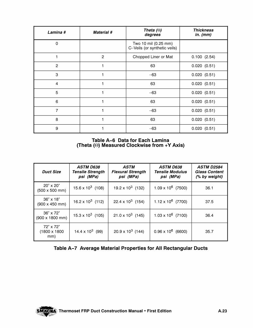
4HERMOSET &20 $UCT #ONSTRUCTION -ANUAL � &IRST %DITION !���
,AMINA � -ATERIAL � 4HETA �QDEGREES
4HICKNESSIN� �MM
� 4WO �� MIL ����� MM#â6EILS �OR SYNTHETIC VEILS
� � #HOPPED ,INER OR -AT ����� �����
� � �� ����� �����
� � � ����� �����
� � �� ����� �����
� � � ����� �����
� � �� ����� �����
� � � ����� �����
� � �� ����� �����
� � � ����� �����
4ABLE ! � $ATA FOR %ACH ,AMINA�4HETA �Q -EASURED #LOCKWISE FROM �9 !XIS
$UCT 3IZE!34- $���
4ENSILE 3TRENGTHPSI �-0A
!34-&LEXURAL 3TRENGTH
PSI �-0A
!34- $���4ENSILE -ODULUS
PSI �-0A
!34- $����'LASS #ONTENT�� BY WEIGHT
��ì X ��ì���� X ��� MM ���� X ��� ���� ���� X ��� ���� ���� X ��� ����� ����
��ì X ��ì���� X ��� MM ���� X ��� ���� ���� X ��� ���� ���� X ��� ����� ����
��ì X ��ì���� X ���� MM ���� X ��� ���� ���� X ��� ���� ���� X ��� ����� ����
��ì X ��ì����� X ����
MM���� X ��� ��� ���� X ��� ���� ���� X ��� ����� ����
4ABLE ! � !VERAGE -ATERIAL 0ROPERTIES FOR !LL 2ECTANGULAR $UCTS

4HERMOSET &20 $UCT #ONSTRUCTION -ANUAL � &IRST %DITION!���
!�� 2%&%2%.#%$ $/#5-%.43
A.1 Baker, E.H., Kovalevsky, L. and Rish, F.L.,Structural Analysis of Shells, Robert E. Krieger Pub-lishing Co., Malabar, Florida, 1981, Chapter 11
A.2 Timoshenko, S. and Woinowsky–Krieger, S.,Theory of Plates and Shells, McGraw–Hill Books,Second Edition, 1959.
A.3 Way, Stewart, “Uniformly Loaded, Clamped,Rectangular Plates with Large Deflection”, Proceed-ings of the Fifth International Congress for AppliedMechanics, 1938, pages 123–128.

4HERMOSET &20 $UCT #ONSTRUCTION -ANUAL � &IRST %DITION !���
4()3 0!'% ).4%.4)/.!,,9 ,%&4 ",!.+

APPENDIX B
CHEMICAL RESISTANCE OFFRP DUCT
#(%-)#!, 2%3)34!.#% /& &20 $5#4!00%.$)8 "
4HERMOSET &20 $UCT #ONSTRUCTION -ANUAL � &IRST %DITION "��
"�� ).42/$5#4)/.
The resistance of FRP composite laminates to aggres-sive corrosive environments is a primary reason forspecifying FRP duct over other alternative materials.FRP duct can be used to handle a wide range of chem-icals, at varying elevated temperatures depending onthe type of thermosetting resin selected.
The FRP duct can be designed and fabricated to pro-vide for chemical resistance, flame retardance, sur-face conductivity, weathering, abrasion resistanceand external chemical attack from spillage.
Successful long term laminate performance requiresselection of the correct thermosetting resin to handlethe chemical and temperature conditions, and also theproper design, fabrication, and field installation of theFRP duct system.
"�� #(%-)#!, 2%3)34!.#%
The chemical resistance characteristics of FRP com-posite laminates are determined by corrosion testingin accordance with ASTM C581 or by case historiesof successful applications in the field.
ASTM C581 calls for corrosion test coupons duplicat-ing the corrosion barrier (VMMV), and resin rich sur-faces on both sides and the cut edges sealed with cata-lyzed resin to prevent edge attack. These testlaminates are immersed in the corrodent for periodsof 3, 6, and 12 months. The specimens are then re-moved, cleaned, and sent for physical testing. Reten-tion of physical strength, along with visual inspectionfor signs of attack, are the main criteria for the evalua-tion of FRP laminates for chemical service.
The total immersion of FRP coupons in a chemicalmedia is generally a more severe test than the vaporphase corrosive conditions a duct system will actuallyexperience. Therefore, published chemical resistancedata for FRP is more favorable when applied to fumeduct in air handling applications.
While metallic corrosion testing is based on materialdegradation as evidenced by surface attack, etching,pitting, intergranular or galvanic attack, where mate-rial loss can be used to calculate a corrosion rate topredict service life. Non–metallics are evaluated dif-ferently. Service life for non metallics is based onstrength retention, weight or volume change and visu-al appearance. Case histories in any given environ-ment are the most reliable sources of information.
Table B- 1 is intended as a guide for selecting a suit-able resin for fume handling FRP duct applications.If the application is severe or questionable, contactyour resin producer for resin recommendations. If thecorrosive conditions are very severe, then chemicaltesting may be necessary to determine a suitable ther-mosetting resin to handle the application. In extremecases, consider a dual laminate, using a more corro-sion resistant thermoplastic liner in place of the stan-dard FRP corrosion barrier, with an FRP outer struc-tural laminate for strength.
Note: Table B- 1, Typical Chemical Resistance ofVarious Resins Used in FRP Duct, is reprinted withpermission from the Fiberglass Pipe Handbook, 1992Edition, courtesy of Fiberglass Pipe Institute of theSPI Composites Institute.
Some corrodents listed in the original Fiberglass PipeHandbook table have not been included in Table B- 1because they were not deemed relevant to fume andexhaust duct applications.
In some applications, a “Corrosion Allowance” con-sisting of one to two additional plies of 1–1/2 ozchopped strand mat is added to the corrosion barrierto combat permeation effects. The added thicknessprovides corrosion protection and maintains the struc-tural integrity of the FRP laminate.
Note: The data in Table B–1 is listed for the followingtemperatures: 120̂F (49̂ C) and 210̂ F (99̂ C), anda max 180̂F (82̂ C) for ISO resins, and 150̂F(66̂ C) for ORTHO resins.

"��
4HERM
OSET
&20$UCT
#ONSTRU
CTION-AN
UAL
�&IRST
%DITIO
N
"ISPHENOL !6INYL %STER
.OVOLAC6INYL %STER
"ISPHENOL !&UMARATE0OLYESTER
#HLORENDIC!CID 0OLYESTER
)SOPHTHALIC!CID 0OLYESTER
/RTHOPHTALIC!CID 0OLYESTER
4EMPERATURE ^& ��� ��� ��� ��� ��� ��� ��� ��� ��� ��� ��� ���
!CETALDEHYDE . . 2 . . . . . . . . .!CETIC !CID� ��� 2 2 2 2 2 2 2 2 2 . . .!CETONE� ��� . . 2 . . . . . . . . .!LCOHOL� ALLYL . . . . . . . . . . . .!LCOHOL� BENZYL . . # . . . . . . . . .!LCOHOL� BUTYL �NâBUTANOL # . 2 . . . . . . . . .!LCOHOL� BUTYL ��âBUTANOL # . 2 . . . . . . . . .!LCOHOL� ETHYL # . # . # . . . 2 . . .!LCOHOL� HEXYL # . 2 # . . . . . . . .!LCOHOL� ISOPROPYL ��âPROPANOL 2 . 2 . . . . . . . . .!LCOHOL� METHYL . . # . . . . . # . . .!LCOHOL� PROPYL ��âPROPANOL # . 2 . . . . . . . . .!LLYL CHLORIDE . . . . . . . . . . . .!MMONIA� GAS # . # . . . . . 2 . . .!MMONIA� LIQUID . . . . . . . . . . . .!MMONIUM SALTS� EXCEPT FLUORIDE 2 2 2 2 2 2 2 # 2 2 2 2!MMONIUM FLUORIDE� ��� 2 . 2 . 2 . 2 . . . . .!MYL ACETATE . . 2 . . . . . . . . .!MYL CHLORIDE . . 2 . . . . . . . . .!NILINE . . . . . . . . . . . .!NILINE HYDROCHLORIDE 2 . 2 . 2 . . . . . . .!QUA REGIA . . ��� ��� 2 . 2 . . . . .!RYLâSULFONIC ACID 2 2 2 2 2 2 . . . . . ."ENZALDEHYDE� ��� . . ��� ��� . . . . . . . .
2 � 'ENERALLY RESISTANT . � 'ENERALLY NOT RESISTANT # � ,ESS RESISTANT THAN 2� BUT STILL SUITABLE FOR SOME CONDITIONS ��� � .OT 2ATED#OPYRIGHT ����� &IBERGLASS 0IPE )NSTITUTE OF THE 30) #OMPOSITES )NSTITUTE� 2EPRINTED WITH 0ERMISSION
4ABLE " � 4YPICAL #HEMICAL 2ESISTANCE OF 6ARIOUS 2ESINS 5SED IN &20 $UCT
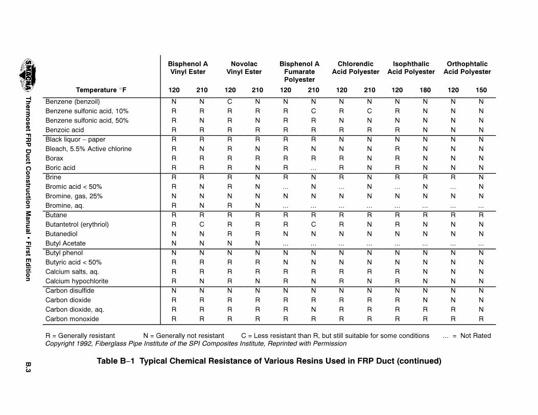
"��
4HERM
OSET
&20$UCT
#ONSTRU
CTION-AN
UAL
�&IRST
%DITIO
N
/RTHOPHTALIC!CID 0OLYESTER
)SOPHTHALIC!CID 0OLYESTER
#HLORENDIC!CID 0OLYESTER
"ISPHENOL !&UMARATE0OLYESTER
.OVOLAC6INYL %STER
"ISPHENOL !6INYL %STER
4EMPERATURE ^& ������������������������������������
"ENZENE �BENZOIL . . # . . . . . . . . ."ENZENE SULFONIC ACID� ��� 2 2 2 2 2 # 2 # 2 . . ."ENZENE SULFONIC ACID� ��� 2 . 2 . 2 2 . . . . . ."ENZOIC ACID 2 2 2 2 2 2 2 2 2 . . ."LACK LIQUOR â PAPER 2 2 2 2 2 2 . . . . . ."LEACH� ���� !CTIVE CHLORINE 2 . 2 . 2 . . . 2 . . ."ORAX 2 2 2 2 2 2 2 . 2 . . ."ORIC ACID 2 2 2 . 2 ��� 2 . 2 . . ."RINE 2 2 2 . 2 . 2 . 2 2 2 ."ROMIC ACID � ��� 2 . 2 . ��� . ��� . ��� . ��� ."ROMINE� GAS� ��� . . . . . . . . . . . ."ROMINE� AQ� 2 . 2 . ��� ��� ��� ��� ��� ��� ��� ���"UTANE 2 2 2 2 2 2 2 2 2 2 2 2"UTANTETROL �ERYTHRIOL 2 # 2 2 2 # 2 . 2 . . ."UTANEDIOL . . 2 2 . . . . . . . ."UTYL !CETATE . . . . ��� ��� ��� ��� ��� ��� ��� ���"UTYL PHENOL . . . . . . . . . . . ."UTYRIC ACID � ��� 2 2 2 2 . . . . . . . .#ALCIUM SALTS� AQ� 2 2 2 2 2 2 2 2 2 . . .#ALCIUM HYPOCHLORITE 2 . 2 . 2 . 2 . 2 . . .#ARBON DISULFIDE . . . . . . . . . . . .#ARBON DIOXIDE 2 2 2 2 2 2 2 2 2 . . .#ARBON DIOXIDE� AQ� 2 2 2 2 2 . 2 2 2 2 2 .#ARBON MONOXIDE 2 2 2 2 2 2 2 2 2 2 2 2
2 � 'ENERALLY RESISTANT . � 'ENERALLY NOT RESISTANT # � ,ESS RESISTANT THAN 2� BUT STILL SUITABLE FOR SOME CONDITIONS ��� � .OT 2ATED#OPYRIGHT ����� &IBERGLASS 0IPE )NSTITUTE OF THE 30) #OMPOSITES )NSTITUTE� 2EPRINTED WITH 0ERMISSION
4ABLE " � 4YPICAL #HEMICAL 2ESISTANCE OF 6ARIOUS 2ESINS 5SED IN &20 $UCT �CONTINUED
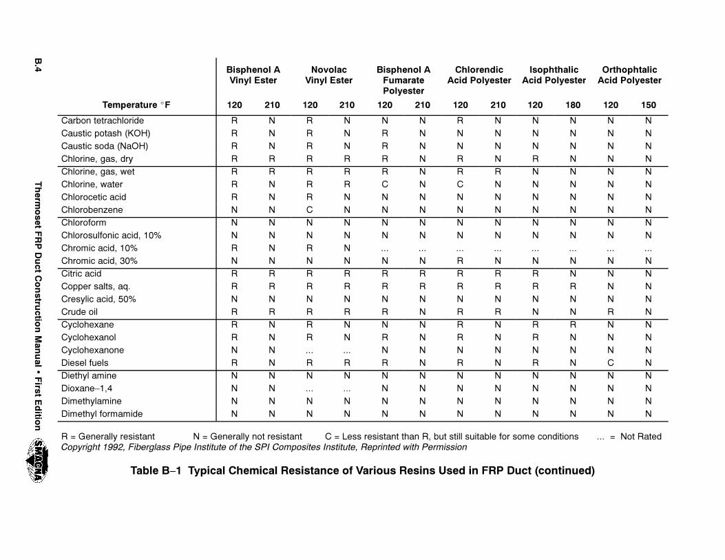
"��
4HERM
OSET
&20$UCT
#ONSTRU
CTION-AN
UAL
�&IRST
%DITIO
N
/RTHOPHTALIC!CID 0OLYESTER
)SOPHTHALIC!CID 0OLYESTER
#HLORENDIC!CID 0OLYESTER
"ISPHENOL !&UMARATE0OLYESTER
.OVOLAC6INYL %STER
"ISPHENOL !6INYL %STER
4EMPERATURE ^& ������������������������������������
#ARBON TETRACHLORIDE 2 . 2 . . . 2 . . . . .#AUSTIC POTASH �+/( 2 . 2 . 2 . . . . . . .#AUSTIC SODA �.A/( 2 . 2 . 2 . . . . . . .#HLORINE� GAS� DRY 2 2 2 2 2 . 2 . 2 . . .#HLORINE� GAS� WET 2 2 2 2 2 . 2 2 . . . .#HLORINE� WATER 2 . 2 2 # . # . . . . .#HLOROCETIC ACID 2 . 2 . . . . . . . . .#HLOROBENZENE . . # . . . . . . . . .#HLOROFORM . . . . . . . . . . . .#HLOROSULFONIC ACID� ��� . . . . . . . . . . . .#HROMIC ACID� ��� 2 . 2 . ��� ��� ��� ��� ��� ��� ��� ���#HROMIC ACID� ��� . . . . . . 2 . . . . .#ITRIC ACID 2 2 2 2 2 2 2 2 2 . . .#OPPER SALTS� AQ� 2 2 2 2 2 2 2 2 2 2 . .#RESYLIC ACID� ��� . . . . . . . . . . . .#RUDE OIL 2 2 2 2 2 . 2 2 . . 2 .#YCLOHEXANE 2 . 2 . . . 2 . 2 2 . .#YCLOHEXANOL 2 . 2 . 2 . 2 . 2 . . .#YCLOHEXANONE . . ��� ��� . . . . . . . .$IESEL FUELS 2 . 2 2 2 . 2 . 2 . # .$IETHYL AMINE . . . . . . . . . . . .$IOXANE�� . . ��� ��� . . . . . . . .$IMETHYLAMINE . . . . . . . . . . . .$IMETHYL FORMAMIDE . . . . . . . . . . . .
2 � 'ENERALLY RESISTANT . � 'ENERALLY NOT RESISTANT # � ,ESS RESISTANT THAN 2� BUT STILL SUITABLE FOR SOME CONDITIONS ��� � .OT 2ATED#OPYRIGHT ����� &IBERGLASS 0IPE )NSTITUTE OF THE 30) #OMPOSITES )NSTITUTE� 2EPRINTED WITH 0ERMISSION
4ABLE " � 4YPICAL #HEMICAL 2ESISTANCE OF 6ARIOUS 2ESINS 5SED IN &20 $UCT �CONTINUED
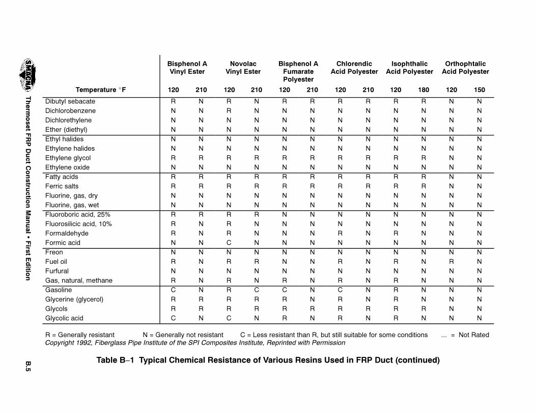
"��
4HERM
OSET
&20$UCT
#ONSTRU
CTION-AN
UAL
�&IRST
%DITIO
N
/RTHOPHTALIC!CID 0OLYESTER
)SOPHTHALIC!CID 0OLYESTER
#HLORENDIC!CID 0OLYESTER
"ISPHENOL !&UMARATE0OLYESTER
.OVOLAC6INYL %STER
"ISPHENOL !6INYL %STER
4EMPERATURE ^& ������������������������������������
$IBUTYL SEBACATE 2 . 2 . 2 2 2 2 2 2 . .$ICHLOROBENZENE . . 2 . . . . . . . . .$ICHLORETHYLENE . . . . . . . . . . . .%THER �DIETHYL . . . . . . . . . . . .%THYL HALIDES . . . . . . . . . . . .%THYLENE HALIDES . . . . . . . . . . . .%THYLENE GLYCOL 2 2 2 2 2 2 2 2 2 2 . .%THYLENE OXIDE . . . . . . . . . . . .&ATTY ACIDS 2 2 2 2 2 2 2 2 2 2 . .&ERRIC SALTS 2 2 2 2 2 2 2 2 2 2 . .&LUORINE� GAS� DRY . . . . . . . . . . . .&LUORINE� GAS� WET . . . . . . . . . . . .&LUOROBORIC ACID� ��� 2 2 2 2 . . . . . . . .&LUOROSILICIC ACID� ��� 2 . 2 . . . . . . . . .&ORMALDEHYDE 2 . 2 . . . 2 . 2 . . .&ORMIC ACID . . # . . . . . . . . .&REON . . . . . . . . . . . .&UEL OIL 2 . 2 2 . . 2 . 2 . 2 .&URFURAL . . . . . . . . . . . .'AS� NATURAL� METHANE 2 . 2 . 2 . 2 . 2 . . .'ASOLINE # . 2 # # . # . 2 . . .'LYCERINE �GLYCEROL 2 2 2 2 2 . 2 . 2 . . .'LYCOLS 2 2 2 2 2 2 2 2 2 2 . .'LYCOLIC ACID # . # . 2 . 2 . 2 . . .
2 � 'ENERALLY RESISTANT . � 'ENERALLY NOT RESISTANT # � ,ESS RESISTANT THAN 2� BUT STILL SUITABLE FOR SOME CONDITIONS ��� � .OT 2ATED#OPYRIGHT ����� &IBERGLASS 0IPE )NSTITUTE OF THE 30) #OMPOSITES )NSTITUTE� 2EPRINTED WITH 0ERMISSION
4ABLE " � 4YPICAL #HEMICAL 2ESISTANCE OF 6ARIOUS 2ESINS 5SED IN &20 $UCT �CONTINUED
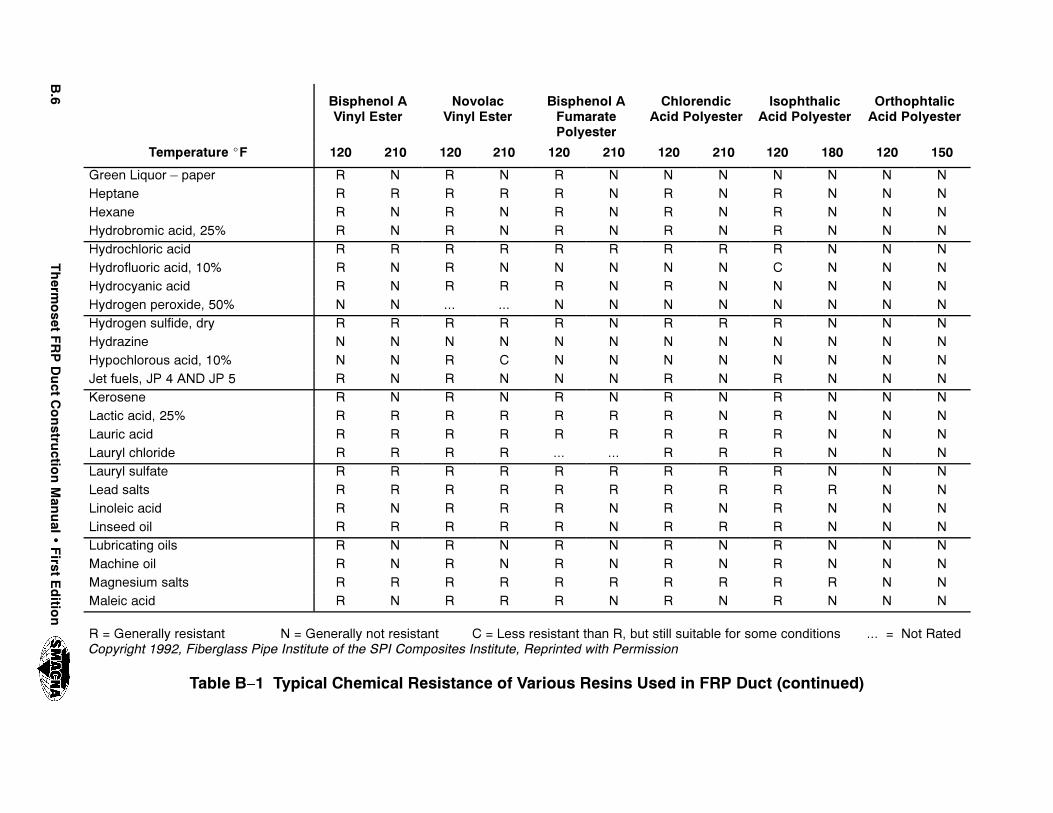
"��
4HERM
OSET
&20$UCT
#ONSTRU
CTION-AN
UAL
�&IRST
%DITIO
N
/RTHOPHTALIC!CID 0OLYESTER
)SOPHTHALIC!CID 0OLYESTER
#HLORENDIC!CID 0OLYESTER
"ISPHENOL !&UMARATE0OLYESTER
.OVOLAC6INYL %STER
"ISPHENOL !6INYL %STER
4EMPERATURE ^& ������������������������������������
'REEN ,IQUOR â PAPER 2 . 2 . 2 . . . . . . .(EPTANE 2 2 2 2 2 . 2 . 2 . . .(EXANE 2 . 2 . 2 . 2 . 2 . . .(YDROBROMIC ACID� ��� 2 . 2 . 2 . 2 . 2 . . .(YDROCHLORIC ACID 2 2 2 2 2 2 2 2 2 . . .(YDROFLUORIC ACID� ��� 2 . 2 . . . . . # . . .(YDROCYANIC ACID 2 . 2 2 2 . 2 . . . . .(YDROGEN PEROXIDE� ��� . . ��� ��� . . . . . . . .(YDROGEN SULFIDE� DRY 2 2 2 2 2 . 2 2 2 . . .(YDRAZINE . . . . . . . . . . . .(YPOCHLOROUS ACID� ��� . . 2 # . . . . . . . .*ET FUELS� *0 � !.$ *0 � 2 . 2 . . . 2 . 2 . . .+EROSENE 2 . 2 . 2 . 2 . 2 . . .,ACTIC ACID� ��� 2 2 2 2 2 2 2 . 2 . . .,AURIC ACID 2 2 2 2 2 2 2 2 2 . . .,AURYL CHLORIDE 2 2 2 2 ��� ��� 2 2 2 . . .,AURYL SULFATE 2 2 2 2 2 2 2 2 2 . . .,EAD SALTS 2 2 2 2 2 2 2 2 2 2 . .,INOLEIC ACID 2 . 2 2 2 . 2 . 2 . . .,INSEED OIL 2 2 2 2 2 . 2 2 2 . . .,UBRICATING OILS 2 . 2 . 2 . 2 . 2 . . .-ACHINE OIL 2 . 2 . 2 . 2 . 2 . . .-AGNESIUM SALTS 2 2 2 2 2 2 2 2 2 2 . .-ALEIC ACID 2 . 2 2 2 . 2 . 2 . . .
2 � 'ENERALLY RESISTANT . � 'ENERALLY NOT RESISTANT # � ,ESS RESISTANT THAN 2� BUT STILL SUITABLE FOR SOME CONDITIONS ��� � .OT 2ATED#OPYRIGHT ����� &IBERGLASS 0IPE )NSTITUTE OF THE 30) #OMPOSITES )NSTITUTE� 2EPRINTED WITH 0ERMISSION
4ABLE " � 4YPICAL #HEMICAL 2ESISTANCE OF 6ARIOUS 2ESINS 5SED IN &20 $UCT �CONTINUED
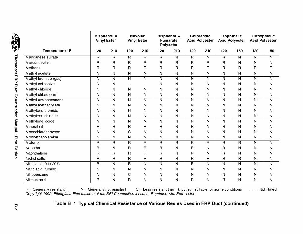
"��
4HERM
OSET
&20$UCT
#ONSTRU
CTION-AN
UAL
�&IRST
%DITIO
N
/RTHOPHTALIC!CID 0OLYESTER
)SOPHTHALIC!CID 0OLYESTER
#HLORENDIC!CID 0OLYESTER
"ISPHENOL !&UMARATE0OLYESTER
.OVOLAC6INYL %STER
"ISPHENOL !6INYL %STER
4EMPERATURE ^& ������������������������������������
-ANGANESE SULFATE 2 2 2 2 2 . 2 . 2 . . .-ERCURIC SALTS 2 2 2 2 2 2 2 2 2 . . .-ETHANE 2 2 2 2 2 2 2 2 2 2 2 2-ETHYL ACETATE . . . . . . . . . . . .-ETHYL BROMIDE �GAS . . . . . . . . . . . .-ETHYL CELLOSOLVE . . ��� ��� . . . . . . . .-ETHYL CHLORIDE . . . . . . . . . . . .-ETHYL CHLOROFORM . . . . . . . . . . . .-ETHYL CYCLOHEXANONE . . . . . . . . . . . .-ETHYL METHACRYLATE . . . . . . . . . . . .-ETHYLENE BROMIDE . . . . . . . . . . . .-ETHYLENE CHLORIDE . . . . . . . . . . . .-ETHYLENE IODIDE . . . . . . . . . . . .-INERAL OIL 2 2 2 2 2 . 2 . 2 . . .-ONOCHLOROBENZENE . . # . . . . . . . . .-ONOETHANOLAMINE . . . . . . . . . . . .-OTOR OIL 2 2 2 2 2 2 2 2 2 2 . ..APHTHA 2 . 2 2 2 . 2 . 2 . . ..APHTHALENE 2 2 2 2 2 . . . 2 . . ..ICKEL SALTS 2 2 2 2 2 2 2 2 2 2 . ..ITRIC ACID� � TO ��� 2 . 2 . . . 2 . . . . ..ITRIC ACID� FUMING . . . . . . . . . . . ..ITROBENZENE . . # . . . . . . . . ..ITROUS ACID 2 . 2 . . . 2 . 2 . . .
2 � 'ENERALLY RESISTANT . � 'ENERALLY NOT RESISTANT # � ,ESS RESISTANT THAN 2� BUT STILL SUITABLE FOR SOME CONDITIONS ��� � .OT 2ATED#OPYRIGHT ����� &IBERGLASS 0IPE )NSTITUTE OF THE 30) #OMPOSITES )NSTITUTE� 2EPRINTED WITH 0ERMISSION
4ABLE " � 4YPICAL #HEMICAL 2ESISTANCE OF 6ARIOUS 2ESINS 5SED IN &20 $UCT �CONTINUED

"��
4HERM
OSET
&20$UCT
#ONSTRU
CTION-AN
UAL
�&IRST
%DITIO
N
/RTHOPHTALIC!CID 0OLYESTER
)SOPHTHALIC!CID 0OLYESTER
#HLORENDIC!CID 0OLYESTER
"ISPHENOL !&UMARATE0OLYESTER
.OVOLAC6INYL %STER
"ISPHENOL !6INYL %STER
4EMPERATURE ^& ������������������������������������
/LEIC ACID 2 2 2 2 2 . 2 . 2 2 . ./LEUM . . . . . . . . . . . ./XALIC ACID 2 2 ��� 2 2 2 2 2 2 2 . ./ZONE� GAS� �� 2 . 2 . . . . . . . . .0ALMITIC ACID� ��� 2 2 2 2 2 2 2 2 2 2 . .0ALMITIC ACID� ��� 2 2 2 2 2 2 2 2 2 2 . .0ARAFFIN 2 2 2 2 2 2 2 2 2 2 2 20ENTANE 2 . 2 . 2 . 2 . 2 . . .0ERCHLORIC ACID� ��� 2 . 2 . . . . . . . . .0ERCHLOROETHYLENE . . 2 . . . . . . . . .0ETROLEUM� SOUR 2 2 2 2 2 . 2 2 2 . . .0ETROLEUM� REFINED 2 2 2 2 2 . 2 2 2 . 2 .0HENYLCARBINOL . . . . . . . . . . . .0HENYLHYDRAZINE . . . . . . . . . . . .0HOSPHORIC ACID 2 2 2 2 2 2 2 2 2 # . .0HOSPHOROUS� YELLOW . . . . . . . . . . . .0HOSPHOROUS� RED . . . . . . . . . . . .0HOSPHOROUS TRICHLORIDE . . . . . . . . . . . .0HTHALIC ACID 2 2 2 2 2 2 2 2 ��� ��� ��� ���0OTASSIUM SALTS� AQ� 2 2 2 2 2 2 2 2 2 2 . .0OTASSIUM PERMANGANATE� ��� 2 2 2 2 2 . 2 . 2 . . .0ROPANE 2 2 2 2 2 2 2 2 2 2 2 20ROPYLENE DICHLORIDE . . . . . . . . . . . .0ROPYLENE GLYCOL 2 2 2 2 2 . 2 . 2 . . .
2 � 'ENERALLY RESISTANT . � 'ENERALLY NOT RESISTANT # � ,ESS RESISTANT THAN 2� BUT STILL SUITABLE FOR SOME CONDITIONS ��� � .OT 2ATED#OPYRIGHT ����� &IBERGLASS 0IPE )NSTITUTE OF THE 30) #OMPOSITES )NSTITUTE� 2EPRINTED WITH 0ERMISSION
4ABLE " � 4YPICAL #HEMICAL 2ESISTANCE OF 6ARIOUS 2ESINS 5SED IN &20 $UCT �CONTINUED
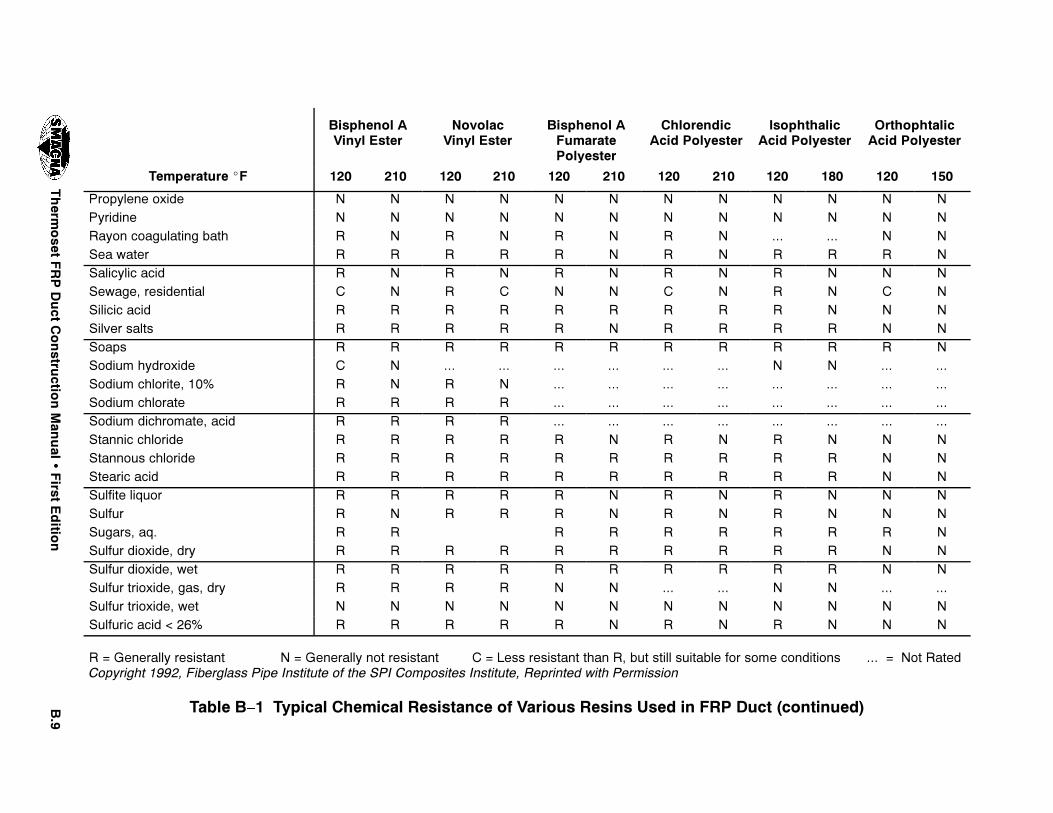
"��
4HERM
OSET
&20$UCT
#ONSTRU
CTION-AN
UAL
�&IRST
%DITIO
N
/RTHOPHTALIC!CID 0OLYESTER
)SOPHTHALIC!CID 0OLYESTER
#HLORENDIC!CID 0OLYESTER
"ISPHENOL !&UMARATE0OLYESTER
.OVOLAC6INYL %STER
"ISPHENOL !6INYL %STER
4EMPERATURE ^& ������������������������������������
0ROPYLENE OXIDE . . . . . . . . . . . .0YRIDINE . . . . . . . . . . . .2AYON COAGULATING BATH 2 . 2 . 2 . 2 . ��� ��� . .3EA WATER 2 2 2 2 2 . 2 . 2 2 2 .3ALICYLIC ACID 2 . 2 . 2 . 2 . 2 . . .3EWAGE� RESIDENTIAL # . 2 # . . # . 2 . # .3ILICIC ACID 2 2 2 2 2 2 2 2 2 . . .3ILVER SALTS 2 2 2 2 2 . 2 2 2 2 . .3OAPS 2 2 2 2 2 2 2 2 2 2 2 .3ODIUM HYDROXIDE # . ��� ��� ��� ��� ��� ��� . . ��� ���3ODIUM CHLORITE� ��� 2 . 2 . ��� ��� ��� ��� ��� ��� ��� ���3ODIUM CHLORATE 2 2 2 2 ��� ��� ��� ��� ��� ��� ��� ���3ODIUM DICHROMATE� ACID 2 2 2 2 ��� ��� ��� ��� ��� ��� ��� ���3TANNIC CHLORIDE 2 2 2 2 2 . 2 . 2 . . .3TANNOUS CHLORIDE 2 2 2 2 2 2 2 2 2 2 . .3TEARIC ACID 2 2 2 2 2 2 2 2 2 2 . .3ULFITE LIQUOR 2 2 2 2 2 . 2 . 2 . . .3ULFUR 2 . 2 2 2 . 2 . 2 . . .3UGARS� AQ� 2 2 2 2 2 2 2 2 2 .3ULFUR DIOXIDE� DRY 2 2 2 2 2 2 2 2 2 2 . .3ULFUR DIOXIDE� WET 2 2 2 2 2 2 2 2 2 2 . .3ULFUR TRIOXIDE� GAS� DRY 2 2 2 2 . . ��� ��� . . ��� ���3ULFUR TRIOXIDE� WET . . . . . . . . . . . .3ULFURIC ACID � ��� 2 2 2 2 2 . 2 . 2 . . .
2 � 'ENERALLY RESISTANT . � 'ENERALLY NOT RESISTANT # � ,ESS RESISTANT THAN 2� BUT STILL SUITABLE FOR SOME CONDITIONS ��� � .OT 2ATED#OPYRIGHT ����� &IBERGLASS 0IPE )NSTITUTE OF THE 30) #OMPOSITES )NSTITUTE� 2EPRINTED WITH 0ERMISSION
4ABLE " � 4YPICAL #HEMICAL 2ESISTANCE OF 6ARIOUS 2ESINS 5SED IN &20 $UCT �CONTINUED
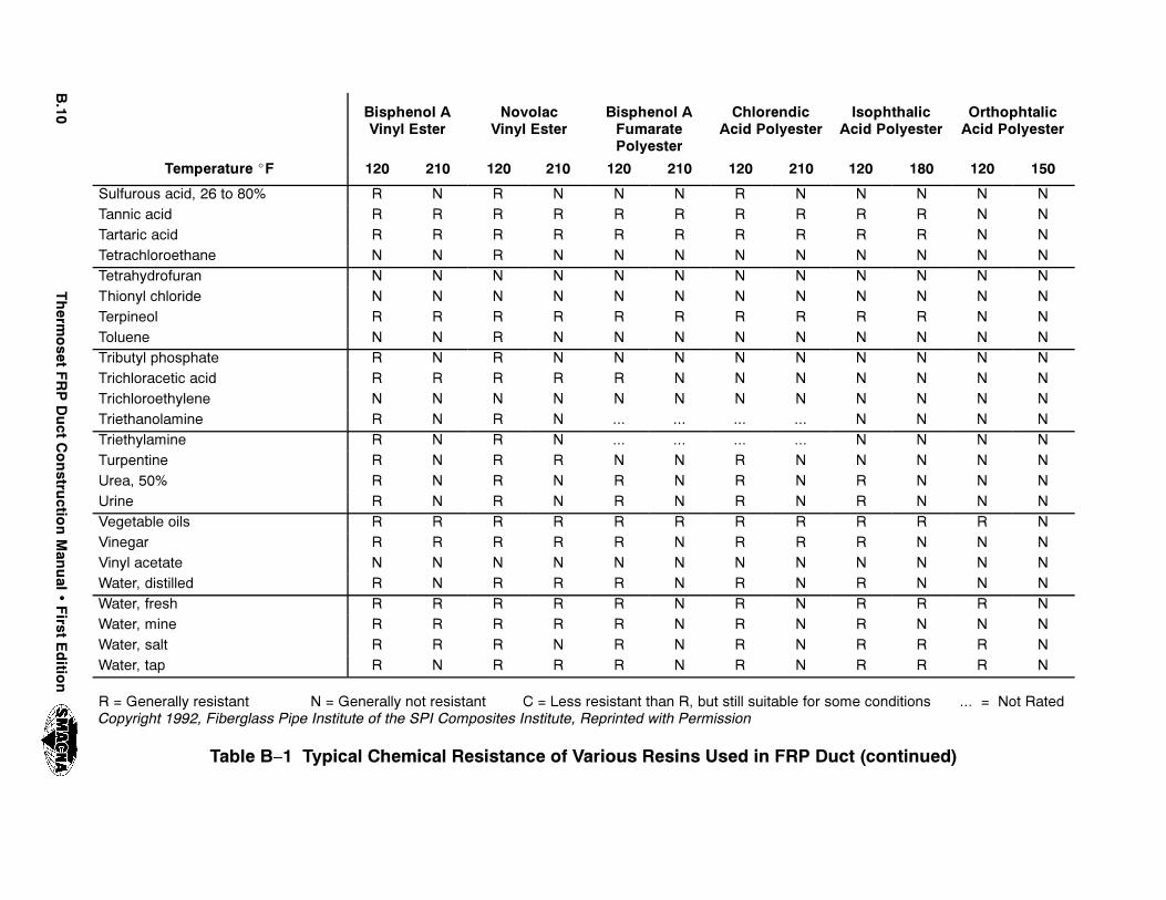
"���
4HERM
OSET
&20$UCT
#ONSTRU
CTION-AN
UAL
�&IRST
%DITIO
N
/RTHOPHTALIC!CID 0OLYESTER
)SOPHTHALIC!CID 0OLYESTER
#HLORENDIC!CID 0OLYESTER
"ISPHENOL !&UMARATE0OLYESTER
.OVOLAC6INYL %STER
"ISPHENOL !6INYL %STER
4EMPERATURE ^& ������������������������������������
3ULFUROUS ACID� �� TO ��� 2 . 2 . . . 2 . . . . .4ANNIC ACID 2 2 2 2 2 2 2 2 2 2 . .4ARTARIC ACID 2 2 2 2 2 2 2 2 2 2 . .4ETRACHLOROETHANE . . 2 . . . . . . . . .4ETRAHYDROFURAN . . . . . . . . . . . .4HIONYL CHLORIDE . . . . . . . . . . . .4ERPINEOL 2 2 2 2 2 2 2 2 2 2 . .4OLUENE . . 2 . . . . . . . . .4RIBUTYL PHOSPHATE 2 . 2 . . . . . . . . .4RICHLORACETIC ACID 2 2 2 2 2 . . . . . . .4RICHLOROETHYLENE . . . . . . . . . . . .4RIETHANOLAMINE 2 . 2 . ��� ��� ��� ��� . . . .4RIETHYLAMINE 2 . 2 . ��� ��� ��� ��� . . . .4URPENTINE 2 . 2 2 . . 2 . . . . .5REA� ��� 2 . 2 . 2 . 2 . 2 . . .5RINE 2 . 2 . 2 . 2 . 2 . . .6EGETABLE OILS 2 2 2 2 2 2 2 2 2 2 2 .6INEGAR 2 2 2 2 2 . 2 2 2 . . .6INYL ACETATE . . . . . . . . . . . .7ATER� DISTILLED 2 . 2 2 2 . 2 . 2 . . .7ATER� FRESH 2 2 2 2 2 . 2 . 2 2 2 .7ATER� MINE 2 2 2 2 2 . 2 . 2 . . .7ATER� SALT 2 2 2 . 2 . 2 . 2 2 2 .7ATER� TAP 2 . 2 2 2 . 2 . 2 2 2 .
2 � 'ENERALLY RESISTANT . � 'ENERALLY NOT RESISTANT # � ,ESS RESISTANT THAN 2� BUT STILL SUITABLE FOR SOME CONDITIONS ��� � .OT 2ATED#OPYRIGHT ����� &IBERGLASS 0IPE )NSTITUTE OF THE 30) #OMPOSITES )NSTITUTE� 2EPRINTED WITH 0ERMISSION
4ABLE " � 4YPICAL #HEMICAL 2ESISTANCE OF 6ARIOUS 2ESINS 5SED IN &20 $UCT �CONTINUED
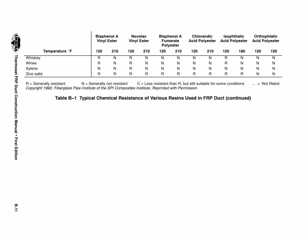
"���
4HERM
OSET
&20$UCT
#ONSTRU
CTION-AN
UAL
�&IRST
%DITIO
N
/RTHOPHTALIC!CID 0OLYESTER
)SOPHTHALIC!CID 0OLYESTER
#HLORENDIC!CID 0OLYESTER
"ISPHENOL !&UMARATE0OLYESTER
.OVOLAC6INYL %STER
"ISPHENOL !6INYL %STER
4EMPERATURE ^& ������������������������������������
7HISKEY 2 . 2 . . . . . 2 . . .7INES 2 . 2 . . . . . 2 . . .8YLENE . . 2 . . . . . . . . .:INE SALTS 2 2 2 2 2 2 2 2 2 2 . .
2 � 'ENERALLY RESISTANT . � 'ENERALLY NOT RESISTANT # � ,ESS RESISTANT THAN 2� BUT STILL SUITABLE FOR SOME CONDITIONS ��� � .OT 2ATED#OPYRIGHT ����� &IBERGLASS 0IPE )NSTITUTE OF THE 30) #OMPOSITES )NSTITUTE� 2EPRINTED WITH 0ERMISSION
4ABLE " � 4YPICAL #HEMICAL 2ESISTANCE OF 6ARIOUS 2ESINS 5SED IN &20 $UCT �CONTINUED

%��� 7KHUPRVHW )53 'XFW &RQVWUXFWLRQ 0DQXDO � )LUVW (GLWLRQ
7+,6 3$*( ,17(17,21$//< /()7 %/$1.

APPENDIX C
ALTERNATE ROUND DUCTDESIGN TABLES
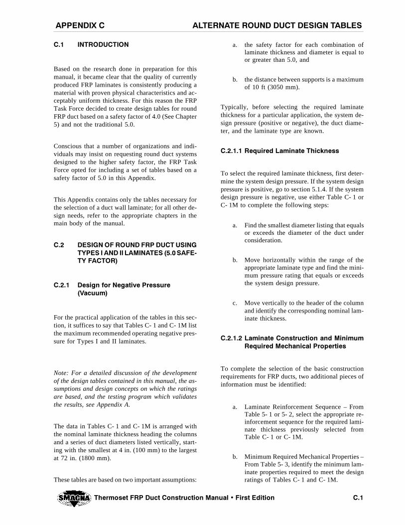
!,4%2.!4% 2/5.$ $5#4 $%3)'. 4!",%3!00%.$)8 #
4HERMOSET &20 $UCT #ONSTRUCTION -ANUAL � &IRST %DITION #��
#�� ).42/$5#4)/.
Based on the research done in preparation for thismanual, it became clear that the quality of currentlyproduced FRP laminates is consistently producing amaterial with proven physical characteristics and ac-ceptably uniform thickness. For this reason the FRPTask Force decided to create design tables for roundFRP duct based on a safety factor of 4.0 (See Chapter5) and not the traditional 5.0.
Conscious that a number of organizations and indi-viduals may insist on requesting round duct systemsdesigned to the higher safety factor, the FRP TaskForce opted for including a set of tables based on asafety factor of 5.0 in this Appendix.
This Appendix contains only the tables necessary forthe selection of a duct wall laminate; for all other de-sign needs, refer to the appropriate chapters in themain body of the manual.
#�� $%3)'. /& 2/5.$ &20 $5#4 53).'490%3 ) !.$ )) ,!-).!4%3 ����3!&% 49 &!#4/2
#���� $ESIGN FOR .EGATIVE 0RESSURE�6ACUUM
For the practical application of the tables in this sec-tion, it suffices to say that Tables C- 1 and C- 1M listthe maximum recommended operating negative pres-sure for Types I and II laminates.
Note: For a detailed discussion of the developmentof the design tables contained in this manual, the as-sumptions and design concepts on which the ratingsare based, and the testing program which validatesthe results, see Appendix A.
The data in Tables C- 1 and C- 1M is arranged withthe nominal laminate thickness heading the columnsand a series of duct diameters listed vertically, start-ing with the smallest at 4 in. (100 mm) to the largestat 72 in. (1800 mm).
These tables are based on two important assumptions:
a. the safety factor for each combination oflaminate thickness and diameter is equal toor greater than 5.0, and
b. the distance between supports is a maximumof 10 ft (3050 mm).
Typically, before selecting the required laminatethickness for a particular application, the system de-sign pressure (positive or negative), the duct diame-ter, and the laminate type are known.
#������ 2EQUIRED ,AMINATE 4HICKNESS
To select the required laminate thickness, first deter-mine the system design pressure. If the system designpressure is positive, go to section 5.1.4. If the systemdesign pressure is negative, use either Table C- 1 orC- 1M to complete the following steps:
a. Find the smallest diameter listing that equalsor exceeds the diameter of the duct underconsideration.
b. Move horizontally within the range of theappropriate laminate type and find the mini-mum pressure rating that equals or exceedsthe system design pressure.
c. Move vertically to the header of the columnand identify the corresponding nominal lam-inate thickness.
#������ ,AMINATE #ONSTRUCTION AND -INIMUM2EQUIRED -ECHANICAL 0ROPERTIES
To complete the selection of the basic constructionrequirements for FRP ducts, two additional pieces ofinformation must be identified:
a. Laminate Reinforcement Sequence – FromTable 5- 1 or 5- 2, select the appropriate re-inforcement sequence for the required lami-nate thickness previously selected fromTable C- 1 or C- 1M.
b. Minimum Required Mechanical Properties –From Table 5- 3, identify the minimum lam-inate properties required to meet the designratings of Tables C- 1 and C- 1M.
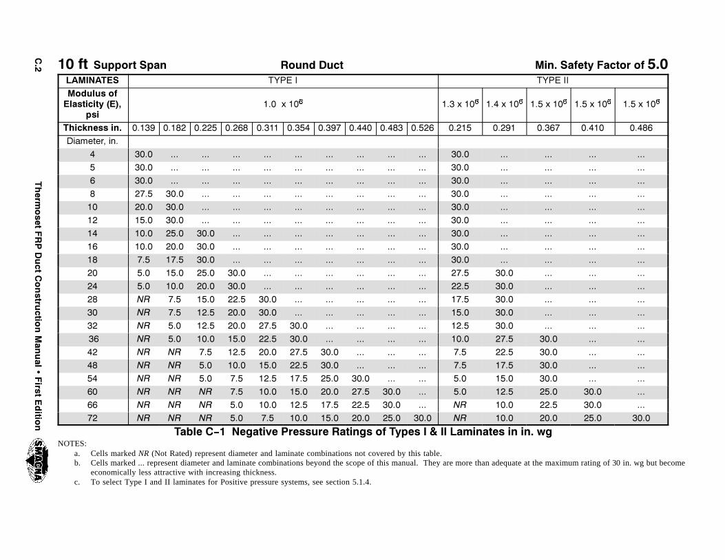
#��
4HERM
OSET
&20$UCT
#ONSTRU
CTION-AN
UAL
�&IRST
%DITIO
N
�� FT 3UPPORT 3PAN 2OUND $UCT -IN� 3AFETY &ACTOR OF ���,!-).!4%3 490% ) 490% ))-ODULUS OF%LASTICITY �%�
PSI��� X �� � ��� X �� � ��� X �� � ��� X �� � ��� X �� � ��� X �� �
4HICKNESS IN� ����� ����� ����� ����� ����� ����� ����� ����� ����� ����� ����� ����� ����� ����� �����$IAMETER� IN�
� ���� ��� ��� ��� ��� ��� ��� ��� ��� ��� ���� ��� ��� ��� ���� ���� ��� ��� ��� ��� ��� ��� ��� ��� ��� ���� ��� ��� ��� ���� ���� ��� ��� ��� ��� ��� ��� ��� ��� ��� ���� ��� ��� ��� ���� ���� ���� ��� ��� ��� ��� ��� ��� ��� ��� ���� ��� ��� ��� ����� ���� ���� ��� ��� ��� ��� ��� ��� ��� ��� ���� ��� ��� ��� ����� ���� ���� ��� ��� ��� ��� ��� ��� ��� ��� ���� ��� ��� ��� ����� ���� ���� ���� ��� ��� ��� ��� ��� ��� ��� ���� ��� ��� ��� ����� ���� ���� ���� ��� ��� ��� ��� ��� ��� ��� ���� ��� ��� ��� ����� ��� ���� ���� ��� ��� ��� ��� ��� ��� ��� ���� ��� ��� ��� ����� ��� ���� ���� ���� ��� ��� ��� ��� ��� ��� ���� ���� ��� ��� ����� ��� ���� ���� ���� ��� ��� ��� ��� ��� ��� ���� ���� ��� ��� ����� .2 ��� ���� ���� ���� ��� ��� ��� ��� ��� ���� ���� ��� ��� ����� .2 ��� ���� ���� ���� ��� ��� ��� ��� ��� ���� ���� ��� ��� ����� .2 ��� ���� ���� ���� ���� ��� ��� ��� ��� ���� ���� ��� ��� ����� .2 ��� ���� ���� ���� ���� ��� ��� ��� ��� ���� ���� ���� ��� ����� .2 .2 ��� ���� ���� ���� ���� ��� ��� ��� ��� ���� ���� ��� ����� .2 .2 ��� ���� ���� ���� ���� ��� ��� ��� ��� ���� ���� ��� ����� .2 .2 ��� ��� ���� ���� ���� ���� ��� ��� ��� ���� ���� ��� ����� .2 .2 .2 ��� ���� ���� ���� ���� ���� ��� ��� ���� ���� ���� ����� .2 .2 .2 ��� ���� ���� ���� ���� ���� ��� .2 ���� ���� ���� ����� .2 .2 .2 ��� ��� ���� ���� ���� ���� ���� .2 ���� ���� ���� ����
4ABLE # � .EGATIVE 0RESSURE 2ATINGS OF 4YPES ) � )) ,AMINATES IN IN� WGNOTES:
a. Cells marked NR (Not Rated) represent diameter and laminate combinations not covered by this table.b. Cells marked ... represent diameter and laminate combinations beyond the scope of this manual. They are more than adequate at the maximum rating of 30 in. wg but become
economically less attractive with increasing thickness.c. To select Type I and II laminates for Positive pressure systems, see section 5.1.4.

#��
4HERM
OSET
&20$UCT
#ONSTRU
CTION-AN
UAL
�&IRST
%DITIO
N
���� MM 3UPPORT 3PAN 2OUND $UCT -IN� 3AFETY &ACTOR OF ���,!-).!4%3 490% ) 490% ))-ODULUS OF%LASTICITY �%�
K0A��� X �� � ��� X �� � ��� X �� � ���� X �� � ���� X �� � ���� X �� �
4 H I C K N E S S � M M ���� ���� ���� ���� ���� ���� ����� ����� ����� ����� ���� ���� ���� ����� �����$IAMETER� MM
��� ���� ��� ��� ��� ��� ��� ��� ��� ��� ��� ���� ��� ��� ��� ������ ���� ��� ��� ��� ��� ��� ��� ��� ��� ��� ���� ��� ��� ��� ������ ���� ��� ��� ��� ��� ��� ��� ��� ��� ��� ���� ��� ��� ��� ������ ���� ���� ��� ��� ��� ��� ��� ��� ��� ��� ���� ��� ��� ��� ������ ���� ���� ��� ��� ��� ��� ��� ��� ��� ��� ���� ��� ��� ��� ������ ���� ���� ��� ��� ��� ��� ��� ��� ��� ��� ���� ��� ��� ��� ������ ���� ���� ���� ��� ��� ��� ��� ��� ��� ��� ���� ��� ��� ��� ������ ���� ���� ���� ��� ��� ��� ��� ��� ��� ��� ���� ��� ��� ��� ������ ���� ���� ���� ��� ��� ��� ��� ��� ��� ��� ���� ��� ��� ��� ������ ���� ���� ���� ���� ��� ��� ��� ��� ��� ��� ���� ���� ��� ��� ������ ���� ���� ���� ���� ��� ��� ��� ��� ��� ��� ���� ���� ��� ��� ������ .2 ���� ���� ���� ���� ��� ��� ��� ��� ��� ���� ���� ��� ��� ������ .2 ���� ���� ���� ���� ��� ��� ��� ��� ��� ���� ���� ��� ��� ������ .2 ���� ���� ���� ���� ���� ��� ��� ��� ��� ���� ���� ��� ��� ������ .2 ���� ���� ���� ���� ���� ��� ��� ��� ��� ���� ���� ���� ��� ������� .2 .2 ���� ���� ���� ���� ���� ��� ��� ��� ���� ���� ���� ��� ������� .2 .2 ���� ���� ���� ���� ���� ��� ��� ��� ���� ���� ���� ��� ������� .2 .2 ���� ���� ���� ���� ���� ���� ��� ��� ���� ���� ���� ��� ������� .2 .2 .2 ���� ���� ���� ���� ���� ���� ��� ���� ���� ���� ���� ������� .2 .2 .2 ���� ���� ���� ���� ���� ���� ��� .2 ���� ���� ���� ������� .2 .2 .2 ���� ���� ���� ���� ���� ���� ���� .2 ���� ���� ���� ����
4ABLE # �- .EGATIVE 0RESSURE 2ATINGS OF 4YPES ) � )) ,AMINATES IN 0ANOTES:
a. Cells marked NR (Not Rated) represent diameter and laminate combinations not covered by this table.b. Cells marked ... represent diameter and laminate combinations beyond the scope of this manual. They are more than adequate at the maximum rating of 30 in. wg but become
economically less attractive with increasing thickness.c. To select Type I and II laminates for Positive pressure systems, see section 5.1.4.

4HERMOSET &20 $UCT #ONSTRUCTION -ANUAL � &IRST %DITION#��
4()3 0!'% ).4%.4)/.!,,9 ,%&4 ",!.+

4HERMOSET &20 $UCT #ONSTRUCTION -ANUAL � &IRST %DITION #��
#�� $%3)'. /& 2/5.$ &20 $5#4 53).'&),!-%.4 7/5.$ �490% 8 ,!-) .!4%3 ���� 3!&%49 &!#4/2
#���� $ESIGN FOR .EGATIVE 0RESSURE�6ACUUM
For the practical application of the tables in this sec-tion, it suffices to say that Tables 5- 9 and 5- 9M listthe maximum recommended operating negative pres-sure for Filament Wound (Type X) laminates.
Note: For a detailed discussion of the developmentof the design tables contained in this manual, the as-sumptions and design concepts on which the ratingsare based, and the testing program which validatesthe results, see Appendix A.
The data in Tables C- 2 and C- 2M is arranged withthe Filament Wound (Type X) laminate combination(S1 through S13) heading the columns and a series ofduct diameters listed vertically, starting with thesmallest at 4 in. (100 mm) to the largest at 72 in. (1800mm).
The tables are based on two important assumptions:
a. the safety factor for each combination oflaminate thickness and diameter is equal toor greater than 5.0, and
b. the distance between supports is a maximumof 10 ft (3050 mm).
Typically, before selecting the required laminatethickness for a particular application, the system de-sign pressure (positive or negative), the duct diame-ter, and the laminate type are known.
#������ 2EQUIRED ,AMINATE 4HICKNESS
To select the required laminate thickness, first deter-mine the system design pressure. If the system designpressure is positive, go to section 5.2.4. If the systemdesign pressure is negative, use either Table C- 2 orC- 2M to complete the following steps:
a. Find the smallest diameter listing that equalsor exceeds the diameter of the duct underconsideration.
b. Move horizontally and find the minimumpressure rating that equals or exceeds thesystem design pressure.
c. Move vertically to the header of the columnand identify the corresponding laminatecombination.
#������ ,AMINATE #ONSTRUCTION AND -INIMUM2EQUIRED -ECHANICAL 0ROPERTIES
To complete the selection of the basic constructionrequirements for FRP ducts fabricated from FilamentWound (Type X) laminates and operating under anegative design pressure, two more pieces of informa-tion must be identified:
a. Composite Laminate Structure – From Table5- 6, select the appropriate composite lami-nate structure corresponding to the laminatecombination previously selected from TableC- 2 or C- 2M.
b. Minimum Required Mechanical Properties –From Table 5- 7, identify the minimum lam-inate mechanical properties required to meetthe design ratings of Tables C- 2 and C- 2M.

#��
4HERM
OSET
&20$UCT
#ONSTRU
CTION-AN
UAL
�&IRST
%DITIO
N
�� FT 3UPPORT 3PAN 2OUND $UCT -IN� 3AFETY &ACTOR OF ���,!-).!4%3 3� 3� 3� 3� 3� 3�� 3�� 3��$IAMETER� IN�
� ���� ��� ��� ��� ��� ��� ��� ���� ���� ��� ��� ��� ��� ��� ��� ���� ���� ��� ��� ��� ��� ��� ��� ���� ���� ��� ��� ��� ��� ��� ��� ����� ���� ��� ��� ��� ��� ��� ��� ����� ���� ��� ��� ��� ��� ��� ��� ����� ���� ���� ��� ��� ��� ��� ��� ����� ���� ���� ��� ��� ��� ��� ��� ����� ���� ���� ��� ��� ��� ��� ��� ����� ���� ���� ���� ��� ��� ��� ��� ����� ���� ���� ���� ��� ��� ��� ��� ����� ��� ���� ���� ���� ��� ��� ��� ����� ��� ���� ���� ���� ��� ��� ��� ����� ��� ���� ���� ���� ��� ��� ��� ����� ��� ���� ���� ���� ���� ��� ��� ����� .2 ��� ���� ���� ���� ��� ��� ����� .2 ��� ���� ���� ���� ���� ��� ����� .2 ��� ���� ���� ���� ���� ��� ����� .2 ��� ��� ���� ���� ���� ���� ����� .2 .2 ��� ���� ���� ���� ���� ����� .2 .2 ��� ���� ���� ���� ���� ����
4ABLE # � .EGATIVE 0RESSURE 2ATINGS OF &ILAMENT 7OUND �4YPE 8 ,AMINATES IN IN� WG
NOTES:
a. Cells marked NR (Not Rated) represent diameter and laminate combinations not covered by this table.b. Cells marked ... represent diameter and laminate combinations beyond the scope of this manual. They are more than adequate at the maximum rating
of 30 in. wg but become economically less attractive with increasing thickness.c. To select filament wound laminates for Positive pressure systems see section 5.2.4.

#��
4HERM
OSET
&20$UCT
#ONSTRU
CTION-AN
UAL
�&IRST
%DITIO
N
���� MM 3UPPORT 3PAN 2OUND $UCT -IN� 3AFETY &ACTOR OF ���,!-).!4%3 3� 3� 3� 3� 3� 3�� 3�� 3��
$IAMETER� MM��� ���� ��� ��� ��� ��� ��� ��� ������ ���� ��� ��� ��� ��� ��� ��� ������ ���� ��� ��� ��� ��� ��� ��� ������ ���� ��� ��� ��� ��� ��� ��� ������ ���� ��� ��� ��� ��� ��� ��� ������ ���� ��� ��� ��� ��� ��� ��� ������ ���� ���� ��� ��� ��� ��� ��� ������ ���� ���� ��� ��� ��� ��� ��� ������ ���� ���� ��� ��� ��� ��� ��� ������ ���� ���� ���� ��� ��� ��� ��� ������ ���� ���� ���� ��� ��� ��� ��� ������ ���� ���� ���� ���� ��� ��� ��� ������ ���� ���� ���� ���� ��� ��� ��� ������ ���� ���� ���� ���� ��� ��� ��� ������ ���� ���� ���� ���� ���� ��� ��� ������� .2 ���� ���� ���� ���� ��� ��� ������� .2 ���� ���� ���� ���� ���� ��� ������� .2 ���� ���� ���� ���� ���� ��� ������� .2 ���� ���� ���� ���� ���� ���� ������� .2 .2 ���� ���� ���� ���� ���� ������� .2 .2 ���� ���� ���� ���� ���� ����
4ABLE #â�- .EGATIVE 0RESSURE 2ATINGS OF &ILAMENT 7OUND �4YPE 8 ,AMINATES IN 0A
NOTES:
a. Cells marked NR (Not Rated) represent diameter and laminate combinations not covered by this table.b. Cells marked ... represent diameter and laminate combinations beyond the scope of this manual. They are more than adequate at the maximum rating of
30 in. wg but become economically less attractive with increasing thickness.c. To select filament wound laminates for Positive pressure systems see section 5.2.4.

&�� 7KHUPRVHW )53 'XFW &RQVWUXFWLRQ 0DQXDO � )LUVW (GLWLRQ
7+,6 3$*( ,17(17,21$//< /()7 %/$1.

APPENDIX D
GLOSSARY

',/33!29!00%.$)8 $
4HERMOSET &20 $UCT #ONSTRUCTION -ANUAL � &IRST %DITION $��
Glossary is reprinted with permission from ASME RTP–1–1995, courtesy of the American Society of MechanicalEngineers.
– A –
accelerator – a material added to the resin to increasethe rate of polymerization (curing).
axial – in the direction of the axis (lengthwise center-line) of the equipment.
– B –
Barcol hardness test – test to determine the degreeof cure by measuring resin hardness. The Barcol Im-pressor is the instrument used for measuring polyesterand vinyl ester resin hardness (ASTM D2583).
binder – chemical treatment applied to the randomarrangement of glass fibers to give integrity to mats.Specific binders are utilized to promote chemicalcompatibility with the various laminating resins used.
blister – raised spot on the surface of a laminatecaused by a subsurface air void.
bonding – joining of two or more parts by adhesiveforces.
bond strength – force per unit area (psi) necessary torupture a bond in interlaminar shear.
burned areas – areas of laminate showing evidenceof decomposition (e.g., discoloration or cracking) dueto excessive resin exotherm.
burn out (burn off) – thermal decomposition of or-ganic materials (resins and binders) from a laminatespecimen in order to determine the weight percent ofresin and glass reinforcement (synthetic reinforce-ment decompose together with the resin and binder).
– C –
“C” glass – a borosilicate glass fiber used to producea very light fabric known assurfacing veil.
catalyst – an organic peroxide material used to acti-vate the polymerization reaction of a resin, causingit to harden (polymerization initiator).
chopped strand mat – reinforcement made from ran-domly oriented glass strands that are held together inmat form using binder. Each strand has a sizing.
chopper gun – a machine that is used to cut continu-ous fiberglass roving to predetermined lengths (usual-ly 1/2 to 2 in. (12 to 50 mm) and propel the cut strandsto the mold surface. In the spray–up process, a cata-lyzed resin spray is deposited simultaneously on themold. When intersperse layers are provided in fila-ment winding, the resin spray is often not used.
classification of laminates – for contact molded andfor filament wound.
contact molding – process for molding FRP in whichreinforcement and resin are placed in or on a mold.Cure is with out the application of pressure on the ma-terials, either at room temperature using a catalyst–promoter system or by heat in an oven. Includes bothhand lay–up and spray–up.
corrosion layer (barrier) – critical segment of thelaminate consisting of a resin rich inner surface, fol-lowed by an interior layer consisting of two plies ofchopped strand mat. (See section 3.3.)
coverage – in hoop filament winding, the completecovering of the mandrel surface by a single layer ofglass reinforcement and resin. In helical winding, twolayers must be applied to achieve one coverage.
crazing – the formation of tiny hairline cracks invarying degrees throughout the resin matrix, particu-larly in resin–rich areas.

4HERMOSET &20 $UCT #ONSTRUCTION -ANUAL � &IRST %DITION$��
curing agents – materials used to initiate the poly-merization of a resin. The catalyst is the primaryagent. Promoters and accelerators are secondary orassisting agents.
cut edge – end of a laminate resulting from cuttingthat is not protected by a corrosion barrier.
cylindrical – See round (cylindrical) duct.
– D –
delamination – physical separation or loss of bondbetween laminate plies.
design laminate – either a standard laminate whosephysical characteristics are well documented (SeeTables 5- 3 and 5- 7) or alternately, a laminate whosephysical characteristics are substantiated throughtesting. In either case, it is the laminate whoseconstruction sequence will be duplicated in the fab-rication of the duct.
dry spot – an area where the reinforcement fibershave not been sufficiently wetted with resin.
– E –
edge sealing – application of reinforcement and resin,or resin alone, to seal cut edges and provide a corro-sion resistant barrier. The final layer of resin shall beparaffinated.
entrapped air void – cavity in a laminate caused bya trapped gas bubble.
environment – state of the surroundings in contactwith the internal or external surface. Included are thetemperature, pressure, chemical exposure to sunlight,relative humidity, liquids, or gases.
exotherm – evolution of heat by the resin during thepolymerization reaction. The word exotherm is often
used, however, to designate the maximum tempera-ture reached during the polymerization process.
exotherm ply – that ply of chopped strand mat atwhich the lamination process is stopped to allow gela-tion and exotherm of the existing laminate.
exterior layer – outer surface layer of a laminate.(See section 3.5.)
– F –
fiber(glass) – a fine solid thread of glass.
fiberglass roving – a number of strands or filamentsof glass fibers gathered together with little or no twist.
fiberglass woven roving – heavy fabric woven fromglass fiber rovings.
fiber wetting – coating (wetting) of the fiberglasswith resin by means of roll–out or immersion
filament – See fiber.
filament winding – a process for forming FRP partsby winding either dry or resin saturated continuousroving strands onto a rotating mandrel.
fillers – inert materials that are added to the resin toincrease density, increase viscosity, improve abrasionresistance, enhance resin application properties, de-crease resin shrinkage, reduce cost, etc.
fill picks – the rovings in a woven roving that run inthe transverse direction of the fabric, i.e., across theroll width of the fabric.
fit–up – the match between joining parts, elements,or components.
flame retardant resin – halogenated resins that canbe used with or without additives to provide a lami-

4HERMOSET &20 $UCT #ONSTRUCTION -ANUAL � &IRST %DITION $��
nate having reduced flame spread as measured in ac-cordance with NFPA 255, Standard Method of Sur-face Burning Characteristics of Building Materials(UL723, ASTM E84). The resins are not fire retardantin their liquid state.
flame spread rating – index number resulting fromtesting in accordance with NFPA 225, StandardMethod of Surface Burning Characteristics of Build-ing Materials (UL723, ASTM E84).
flange cant â the angle that an entire branch is offfrom being perpendicular to the main run centerline.(See Figure 7- 2.)
flange flatness â maximum deviation from the actualflange face, excluding warpage or perpendicularity.(See Figure 7- 3.)
flange offset â the amount that an entire branch is off-set with respect to the main run centerline. (See Fig-ure 7- 4.)
flange perpendicularity â maximum angle that theplane of the flange inside diameter makes with theplane perpendicular to the duct’s centerline. (See Fig-ure 7- 2.)
flange warpage â the amount that a flange outside di-ameter pulls back from the plane of the inside diame-ter during the cure of the composite laminate. (SeeFigure 7- 3.)
fabricator – producer of FRP equipment. The fabrica-tor combines resin and reinforcing fibers to producethe final product.
FRP – Fiberglass Reinforced Plastic.
– G –
gap filling – the filling of voids between joined parts,elements, or components with resin putty.
gel – the initial jellylike solid phase that develops dur-ing the polymerization of resin.
gel time – time form the initial mixing of the resinwith catalyst to when gelation begins.
glass content – weight percent of glass fiber rein-forcement in the laminate.
gun roving – fiberglass roving designed for use in achopper gun for spray–up application.
– H –
hand lay–up – a method of contact molding whereinthe glass fiber reinforcement is applied to the mold,in the form of chopped strand mat or woven roving,by hand or form a reel. The resin matrix is appliedby various methods including brush, roller, or spraygun. Consolidation of the composite laminate is byrolling.
heat deflection temperature – temperature at whicha specified bar specimen deflects 0.010 in. (0.25 mm)when loaded as a simple beam to a constant 264 psi(see ASTM D648, Test Method for Deflection Tem-perature of Plastics Under Flexural Load). Usually re-fers to a resin casting, not laminate.
helical winding – filament winding where the rein-forcement is placed at some angle (other than 0° or90°) to the axis of rotation.
hot cure – process of increasing the amount of cata-lyst to expedite the cure.
hot patch – several small fiberglass mat tabs, satu-rated with highly catalyzed resin, used to hold buttedor joined parts or components in preparation for bond-ing.
hydrostatic test – pressure test of equipment usingwater as the test medium.
– I –
initiator – See catalyst.

4HERMOSET &20 $UCT #ONSTRUCTION -ANUAL � &IRST %DITION$��
inner surface – resin rich, corrosion resistant surfaceof the corrosion barrier. (See section 3.3.1.)
interior layer – fiber reinforced layer of the corrosionbarrier. (See section 3.3.2.)
intersperse – chopped fiberglass used in a filamentwound laminate, usually in thin layers between wind-ing coverages.
intumescent coating – a coating that when subjectedto heat in excess of 300°F (149°C) swells and charsforming an insulating, fire retardant barrier.
isophthalic polyester – a polyester made fromisophthalic acid.
– J –
joint overlay – an overlay laminate that joins the ad-joining surfaces of two contacting parts or elements.
– L –
laminate – the total of the part constructed by com-bining one or more layers of material (reinforcementand/or resin). As used in this Standard, the corrosionlaminate consists of the corrosion resistant barrier, thestructural layer, and the outer surface.
laminate composition – the sequence of reinforce-ment materials on a type, class, and category basisthat make up a laminate.
laminate element – a part of the structural layer ofa filament wound laminate that is described by thewind angle, number of coverages with supplementaryreinforcement (if used), and the required sequence.
laminate structure – (Type I, Type II, hand lay–up,and filament wound (Type X))– (See section 3.4.)
lamination analysis – procedure by which, given theamount and properties of the resin and the propertiesand orientation of the reinforcement, it is possible tocalculate the elastic properties of the individual layersand the total laminate.
layout – the arrangement and location of parts, ele-ments, or components that reflect the design of aproduct.
leno strands – a pair of warp ends at each edge of awoven fiberglass fabric.
liner – (See corrosion layer (barrier.)
longitudinal – See axial.
– M –
mandrel – mold around which a laminate is formedto fabricate a round section.
Manufacturers – producers of materials of construc-tion, e.g., resin reinforcement fibers, catalysts, com-mon additives, etc.
manway – large nozzle or opening in a vessel for thepurpose of entry by personnel.
materials – ingredients (reinforcement, resins, cata-lysts, and common additives) that are used to fabri-cate the equipment
matrix – resin phase of a fiberglass resin composite.
mold – the form over which or into which resin andreinforcements are placed to form the compositeproduct shape.
mold release agents – See parting agents.
monomer – a basic compound styrene that can reactwith itself to form a polymer.
4HERMOSET &20 $UCT #ONSTRUCTION -ANUAL � &IRST %DITION $��
– O –
overlay – laminates used over base FRP structures tosecure a joint, seal a seam, attach a nozzle, etc.
– P –
paraffinated resin – resin containing a small amountof dissolved paraffin (usually 0.1% to 0.5%). Poly-merization of polyesters is inhibited by contact withthe atmosphere. During cure, the paraffin migrates tothe surface, sealing it against atmosphere exposure.
parting agents – also called mold release agents.Compounds that assist in releasing an FRP part fromits mold.
pit – small crater in the surface of the laminate.
polyester resin – resin produced by the polycondensa-tion of dihydroxy derivatives and dibasic organicacids or anhydrides, wherein at least one componentcontributes ethylene unsaturation yielding resins thatcan be compounded with styryl monomers andreacted to give highly cross–linked thermoset resins.
post–curing – process of applying heat (180 to 200^F(82 to 93̂ C)) to an FRP part, following the exothermcycle. Proper post curing will shorten the time to totalcure.
profile – the roughness (smoothness) of the surface.
promoter – a material that activates the catalystwhich cures the resin. (See accelerator.)
PVA – abbreviation for polyvinyl alcohol, a partingagent.
– Q –
quality assurance – the system by which the Fabrica-tor provides evidence that the quality control systemhas been followed in the construction of the product.
quality control – the system a Fabricator uses to fabri-cate the equipment in compliance with this Manual.
– R –
rectangular duct – a conduit having a rectangularcross- section and used for moving air, alone or incombination with other gases, vapors, or particulatematter.
referee samples – laminate specimens submitted toestablish a level of quality for judging acceptance orrejection of production equipment.
reinforcement – glass fibers having the form ofchopped roving, continuous roving, fabric, orchopped strand mat. These fibers are added to the res-in matrix to strengthen and improve the properties ofthe resin.
release film – film used to facilitate removal of thepart from the mold or mandrel. Oriented polyesterfilm, 3 to 5mil (MYLARº, Types A, S, or D; or ME-LINEX 11º, Types A, O, or 442), has been foundsuitable for this purpose.
resin – the matrix of the laminate.
resin putty – resin filled with clay, fumed silica,milled glass fibers, or other inert materials to provideputty- like consistency.
resin rich layer – term often used to describe the cor-rosion barrier. The term does not imply excessive res-in content.
resin richness – excessive amounts or uneven dis-tribution of resin in the laminate. Such areas are sub-ject to cracking. Resin richness is the result of im-
4HERMOSET &20 $UCT #ONSTRUCTION -ANUAL � &IRST %DITION$��
proper wet–out procedures as well as inadequate orimproper roll–out techniques or drainage.
roll–out – densification of the laminate by workingreinforcement into the resin and the air out of the resinusing a roller (a serrated metal or thermoplastic rolleris often used for this purpose).
rough profile – the result of sanding, machining, orotherwise abrading a laminate surface to produce aroughened surface for bonding.
round (cylindrical) duct – a cylindrical shaped con-duit for moving air, alone or in combination with oth-er gases, vapors, or particulate matter.
roving – a plurality of strands or filaments gatheredtogether with little or no twist in a package known asa roving ball.
RTP – Reinforced Thermoset Plastic (alsosee FRP).
– S –
safety solvent – a non–flammable, non–acetone basedsolvent used for various clean–activities in the FRPfabrication process.
secondary bond strength – adhesive force that holdsa separately cured laminate to the basic substrate lam-inate.
sizing – surface treatment or coating applied to fila-ment to improve the filament–to–resin bond.
spray–up – method of contact molding wherein resinand chopped strands of continuous filament glass fi-ber roving are deposited on the mold directly from achopper gun.
strain – elongation per unit strength.
strand – a plurality of filaments gathered together andbonded with sizing.
structural layer – the portion of the construction pro-viding the primary mechanical strength.
surface preparation – the act of roughening, priming,or otherwise treating laminate surfaces to achieve sur-face conditions that conductive to adhesion of subse-quently applied laminate bonds.
surfacing veil (mat) – thin mat, of fiberglass, synthet-ic organic fiber, or carbon fiber, that is used to rein-force the corrosion resistant resin rich layer on the in-side or outside of equipment.
– T –
Tex – linear density of roving expressed in grams per1000 m.
– U –
unidirectional rovings – continuous parallel rovingstrands of glass fiber held together with periodic crossstrands.
User – organization for which the equipment is beingfabricated.
UV absorber – compounds that are added to resinsto enhance their ultraviolet resistance.
– V –
veil – See surfacing veil.
vinyl ester resin – resin characterized by reactive un-saturation located predominately in terminal posi-tions which can be compounded with styryl mono-mers and reacted to give highly cross–linkedthermoset copolymers. (See section 2.2.4.)
4HERMOSET &20 $UCT #ONSTRUCTION -ANUAL � &IRST %DITION $��
voids – unfilled space caused by air or gas in the resinmix or by entrapment of such gases during lay–up ofindividual plies of glass. Excessive voids reduce thestrength and chemical resistance of the laminate, par-ticularly if the voids are at the resin–glass interface.
– W –
warp ends – the roving in a woven roving which runsin the longitudinal direction of the fabric, i.e., alongthe roll length of the fabric.
wind angle – angle from the axis of rotation at whichthe reinforcement strands are placed in the filamentwinding process.
wind cycle – in filament winding, one traversing ofthe carriage to the end of the mandrel and return tothe original position. Depending on band width, partdiameter, and wind angle, one or more wind cycleswill be needed to achieve one coverage.
– Y –
yield – linear density of roving, expressed in yards perpound.

4HERMOSET &20 $UCT #ONSTRUCTION -ANUAL � &IRST %DITION$��
4()3 0!'% ).4%.4)/.!,,9 ,%&4 ",!.+

APPENDIX E
REFERENCED DOCUMENTS

2%&%2%.#%$ $/#5-%.43!00%.$)8 %
4HERMOSET &20 $UCT #ONSTRUCTION -ANUAL � &IRST %DITION %��
%�� !34-
The following ASTM documents are available from:
ASTM100 Barr Harbor DriveWest Conshohocken, PA 19428–2959Phone: 610–832–9585Fax: 610–832–9555
R ASTM Standard C581–94, DeterminingChemical Resistance of Thermosetting Res-ins Used in Glass–Fiber–Reinforced Struc-tures Intended for Liquid Service.AmericanSociety for Testing and Materials, WestConshohocken, PA. 1994.
R ASTM Standard C582–95, Contact–MoldedReinforced Thermosetting Plastic (RTP)Laminates for Corrosion–Resistant Equip-ment. ibid. 1995.
R ASTM Standard D638–96, Standard TestMethod for Tensile Properties of Plastics.ibid. 1992.
R ASTM Standard D790–96a,Flexural Prop-erties of Unreinforced Plastics and Electri-cal Insulating Materials. ibid. 1996.
R ASTM Standard D883–96, Standard Ter-minology Relating to Plastics. ibid. 1996.
R ASTM Standard D2563–94,ClassifyingVisual Defects in Glass–Reinforced PlasticLaminate Parts. ibid. 1994
R ASTM Standard D2583–95, IndentationHardness of Rigid PLASTICS by Means of aBARCOL Impressor. ibid. 1995.
R ASTM Standard D2584–94, Ignition Loss ofCured Reinforced Resins. ibid. 1994.
R ASTM Standard D3982–92, Contact Molded“Fiberglass” (Glass Fiber Reinforced Ther-mosetting Resin) Duct and Hoods. ibid.1992.
R ASTM Standard E84–96a, Surface BurningCharacteristics of Building Materials. ibid.1996.
R ASTM Standard E662–95, Specific OpticalDensity of Smoke Generated by Solid Mate-rials. ibid. 1995.
%�� .&0! 34!.$!2$3
The following NFPA document is available from:
National Fire Protection Association11 Tracy DriveAvon, MA 02322–9908Phone: 800–344–3555Fax: 800–593–NFPA
R ANSI/NFPA 91, Standard for Exhaust Sys-tems for Air Conveying of Materials. Nation-al Fire Protection Association, Quincy, MA.1995.
%�� !3-% 34!.$!2$3
The following ASME document is available from:
ASMEOrder Department22 Law DriveP.O. Box 2300Fairhill, NJ 07007–2300Phone: 800–843–2763Fax: 973–882–1717
R ANSI/ASME RTP–1–1995 Edition, Rein-forced Thermoset Plastic Corrosion Resist-ant Equipment. American Society of Me-chanical Engineers, New York, NY. 1995.
%�� 3-!#.! 34!.$!2$3
The following SMACNA documents are availablefrom:
4HERMOSET &20 $UCT #ONSTRUCTION -ANUAL � &IRST %DITION%��
SMACNAPublications Department4201 Lafayette Center DriveChantilly, VA 20151–1209Phone: 703–803–2980Fax: 703–803–3732
R SMACNA. Architectural Sheet Metal Manu-al. Sheet Metal and Air Conditioning Con-tractors’ National Association, Inc., Chantil-ly, VA. 1993.
R SMACNA. HVAC Systems Testing, Adjust-ing and Balancing. ibid. 1993.
R SMACNA. HVAC Systems Duct Design.ibid. 1993.
R SMACNA. Thermoplastic Duct (PVC)Construction Manual. ibid. 1995.
%�� /4(%2 34!.$!2$3
The following American Conference of Governmen-tal Industrial Hygienists document is available from:
American Conference of Governmental Indus-trial HygienistsKemper Woods Center1330 Kemper Meadow DriveCincinnati, OH 45240Phone: 513–742–2020Fax: 513–742–3355
R American Conference of Governmental In-dustrial Hygienists.Industrial Ventilation: A
Manual of Recommended Practice. Ameri-can Conference of Governmental IndustrialHygienists, Cincinnati, OH. 1995.
The following AMCA documents are available from:
Air Movement and Control Association Inc.30 W. University DriveArlington Heights, IL 60004Phone: 847–394–0150Fax: 847–253–0088
R AMCA Publication 99. Standards for AirMoving Devices. Air Movement and ControlAssociation Inc., Arlington Heights, IL.1986.
R AMCA Standard 210.Laboratory Methodsfor Testing Fans for Rating. ibid. 1985.
The following Manufacturers Standardization Soci-ety of the Valve and Fittings Industry, Inc. documentis available from:
Manufacturers Standardization Society of theValve and Fittings Industry, Inc.127 Park Street, N.E.Vienna, VA 22180–4602Phone: 703–281–6613Fax: 703–281–6671
R Manufacturers Standardization Society ofthe Valve and Fittings Industry, Inc.SP–58,1993 Edition. Manufacturers Standardiza-tion Society of the Valve and Fittings Indus-try, Inc., Vienna, VA. 1993.

INDEX

).$%8
4HERMOSET &20 $UCT #ONSTRUCTION -ANUAL � &IRST %DITION )��
!Access Openings and End Caps, 7.7
Acids, 2.1, 2.2
Air Bubbles, 3.3, 4.7, 7.1
Air Pollution, 1.1
Alkalies, 2.1, 2.2
ANSI/ASME RTP–1, 5.1, E.1
ANSI/NFPA 91, E.1
Antimony Trioxide, 2.1, 2.2, 2.4
Appearance, 3.3, 7.1, 7.9
Application, 2.5, 5.9, 6.1, 6.9
ASTM, 3.3, 7.1, 7.5, 7.6, 7.8, E.1C581, 3.1, 7.1, B.1, E.1C582, 3.1, 7.9, E.1D2583, 3.3, 7.9, 8.1, E.1D2584, E.1D3982, 3.1, 7.9, E.1D638, 5.1, 5.5, 6.1, E.1D648, D.3D790, 5.5D883, 7.1, E.1E662, E.1E84, 2.1, 2.2, 2.4, D.3, E.1
"Back–draft Dampers, 7.7
Bisphenol A Fumarates, 2.2
Buried Duct, 7.8
#Carbon Veil, 2.5, 3.1
Chlorendic Anhydride, 2.1
Chlorine, 2.4
Chopped Strand Mat, 2.5, 3.1, 7.1, B.1, D.1, D.2,D.3, D.5
Clean–up, 4.4
Cobalt Naphthenate, 2.2, 2.3
Cobalt Octoate, 2.2
Colloidal Suspension, 2.4
Color Stability, 2.2
Composite Material, 1.1, 6.9
Contact Molding, 5.1, 5.9, 6.1, 7.1, D.3, D.6
Continuous Strand Roving, 2.5, 3.1
Corrosion Allowance, B.1
Corrosion Barrier, 3.1, 3.3, 7.1, A.7, A.9, B.1, D.2,D.5
Corrosion Control, 1.1, 2.5
Corrosion Resistance, 1.1, 2.1, 2.2, 2.4, 2.5, 3.1,7.7
Cut Edges, 7.1, D.2
Cylindrical Duct (Round Duct), C.1
$Dampers, 7.3, 7.6, 7.7, 9.2, 9.6, 9.7
Delamination, 3.3, 7.1, D.2
Design Requirements, 7.2
Dispersion, 2.4
DMA, 2.3, 2.4
Drainage, 2.4, 7.8, 9.2, D.6
Drains, 7.7, 9.7
Dry Spots, 7.1, 7.9
Duct Hangers and Supports, 7.3
Durometer, 7.3
%Exothermic Reaction, 2.2
Exterior Surface, 3.1, 3.3, 5.11, 7.1
&Fabrication, 1.1, 1.2, 2.1, 2.2, 2.4, 4.1, 5.1, 5.2,
5.9, 5.10, 6.1, 7.1, 7.9, 8.1, B.1, D.2
Field Installation of FRP Duct, 4.1
Field Wrapped Joints, 4.1
Filament Winding, 1.1, 2.1, 2.2, 2.5, A.7, D.2
Flame Retardant, 2.1, 2.2, 2.4, 3.1, D.2
Flange Requirements, 7.2
Flexible Connections, 7.7, 7.9, 9.7
Foreign Inclusions, 3.3, 7.1
FRP Guide Specifications, 1.2
Fume Hoods, 7.6
Fumed Silicas, 2.4
'Gasket Materials, 7.3

4HERMOSET &20 $UCT #ONSTRUCTION -ANUAL � &IRST %DITION)��
Gel Time, 2.3, 2.4, 4.4, D.3
Glycols, 2.1
GRP, 1.1
(Hand Lay–up, 1.1, 1.2, 2.2, 2.4, 5.1, 6.1, 7.1, D.1,
D.3
Handling, Shipping and Installation, 7.9
Hardness, Barcol, 1.1
Health Concerns, 8.2
High Shear Mixer, 2.4
Hot Patch, 4.4, 4.6, D.3
)Impact Resistance, 2.2
Ingestion, 8.2
Inhalation, 8.2
Initiators, 2.1, 2.2
Inner Surface, 4.1, 7.1, 7.3
Inspection, 2.4, 7.8, 7.9
Interior Layer, 3.1, 7.3, D.1, D.4
Intumescent, 3.1, D.4
*Joining Duct, 4.1, 4.4
Joints, 4.1, 4.4, 4.5
,Laminate Construction, 1.2, 3.1, 3.3, 5.1, 5.9, 6.2,
7.1, A.1, C.1, C.5
Laminates, 2.1, 2.2, 2.4, 3.1, 3.3, 5.1, 5.2, D.1, E.1Filament Wound (Type X), 1.2, 2.1, 3.3, 4.1,
5.1, 5.9, 5.10, 5.12, 5.13, 7.1, 7.2, 7.10, A.1,A.3, C.5
Type I, 1.2, 3.1, 5.1, 6.1, 7.1, 7.2, 7.10, A.1,A.2, C.1
Type II, 1.2, 3.1, 5.1, 6.1, 6.9, 7.1, 7.2, 7.10,A.1, A.2, C.1
Lay–up Procedure, 4.4
Linear Coefficient of Thermal Expansion, 7.7
Louvers, 7.7, 9.8
-Manufacturer’s Shop Review, 7.8
Material Safety Data Sheets (MSDS), 7.10, 8.2
Materials, 1.1, 1.2, 2.1, 2.2, 2.4, 7.1, 7.7, 9.6, D.4
Mechanical Properties, 2.2, 3.3, 5.1, 5.2, 5.9, 6.2,C.1, C.5
MEKP, 2.2, 2.3, 4.4
MYLARQ, D.5
.NEXUSQ, 2.5, 3.1
Nonconformities, 8.1
NPG (Neopentyl Glycol), 2.1
/Odor Abatement, 1.1
Opaque, 2.4
Organic Peroxides, 2.2
0Paraffin Wax, 3.1, 4.1
Pimples, 3.3, 7.1
Pinholes, 3.3
Polymerized, 2.3
1Quality Control, 1.2, 3.3, 7.9, 8.1, D.5
Resin, Catalyzed, 7.3
2Rectangular Duct, 1.1, 6.1, 6.9, 7.2, 7.4, 7.8
Rectangular Duct Corners, 7.2
Reinforcement, 1.1, 1.2, 2.1, 2.5, 3.1, 5.1, 5.2, 6.2,7.1, 7.2, 7.7, C.1, D.5
Release Film, D.5
Requirements, 1.1, 1.2, 3.3, 5.1, 5.2, 6.1, 6.2, 6.9
Resin, 1.1, 1.2, 2.1, 6.1, 8.3, D.5Catalyzed, 1.2, 2.1, B.1Chlorendic, 2.1

4HERMOSET &20 $UCT #ONSTRUCTION -ANUAL � &IRST %DITION )��
Halogenated, 2.4Isophthalic, 2.1Othophthalic, 2.1Polyester, 2.2Thermosetting (or Thermoset), B.1, E.1
Rotating Mandrel, D.2
Round (Cylindrical) Duct, A.1, C.1, C.5
RTP (Also see FRP and GRP), 1.1, 1.2, D.6, E.1
3Safety, 1.2, 2.4, 3.3, 4.4, 5.1, 7.6, 7.7, 7.9, 8.2
Safety Factor, 1.2, 5.9, C.1
Safety Solvent, 4.4, 8.3
Scope, 1.1
Secondary Bonding, 3.3, 4.1
Serrated Roller, 4.1, D.6
Solvents, 2.1, 2.2, 7.10
Spray–chop, 2.5
Sprinklers, 7.8
Standard Elbows and Mitered Joints, 7.3
Static Electricity, 3.1, 7.1
Stiffeners, 1.2, 6.1, 6.9, A.5
Storage, 7.1, 8.3
Structural Layer, 1.1, 2.5, 3.1, 3.3, D.6
Styrene, 4.1, 8.2, 8.3
Surface Hardness, 3.3, 7.1
Surfacing Veil, 2.5, D.6
Synergist (Antimony Trioxide), 2.1, 2.4, 7.1
4Tack Weld, 4.4
Tensile Elongation, 2.2
Terminology, 1.2, 7.1
Thermoplastic, 1.1, 2.1, 7.7, B.1, D.6, E.2
Thermoset Plastic, 1.1, 1.2, D.6, E.1
Thixed, 2.2, 2.4
Thixotropes, 2.4
Tolerances, 4.1, 7.8
Translucent, 2.4
5Uses, 1.1
UV (Ultraviolet), 2.5, 3.1, D.6
UV Stabilizer, 2.5
6Ventilators, 7.7, 9.8
Vinyl Ester, 1.1, 2.2, 2.4, 2.5, D.1, D.6
Viscosity, 2.2, 8.2, D.2
Volume Dampers, 7.6, 9.6
7Weatherability, 2.2
What is FRP, 1.1
Woven Roving, 2.5, 3.1, 5.11, 7.1, 7.7, D.2, D.3,D.7


![Chime Ch intermittently energized IoT devicesam34/publications/chime.pdf · rication testing and debugging [2]. JTAG is used as the primary means of accessing subparts of many such](https://img.pdfslide.us/doc/110x75/5ece399500bbfb522729b0aa/chime-ch-intermittently-energized-iot-am34publicationschimepdf-rication-testing.jpg)


![ENGI 3425 8. Multiple Integration Page 8-01 8. Multiple ...ggeorge/3425/handout/H08MultInt.pdf · A related concept is [mass] moment of inertia 2 2 2 2 ³³ ³³ RR ... second moment](https://img.pdfslide.us/doc/110x75/5b155b587f8b9adc528bddac/engi-3425-8-multiple-integration-page-8-01-8-multiple-ggeorge3425handout.jpg)


![Chime Ch intermittently energized IoT devicesaceslab.org/sites/default/files/chime.pdf · rication testing and debugging [2]. JTAG is used as the primary means of accessing subparts](https://img.pdfslide.us/doc/110x75/5ece397300bbfb522729b057/chime-ch-intermittently-energized-iot-rication-testing-and-debugging-2-jtag-is.jpg)